Embed Size (px)
Citation preview

SMART COLOR SORTING ROBOT
SITI NADRAH BINTI SELAMAT
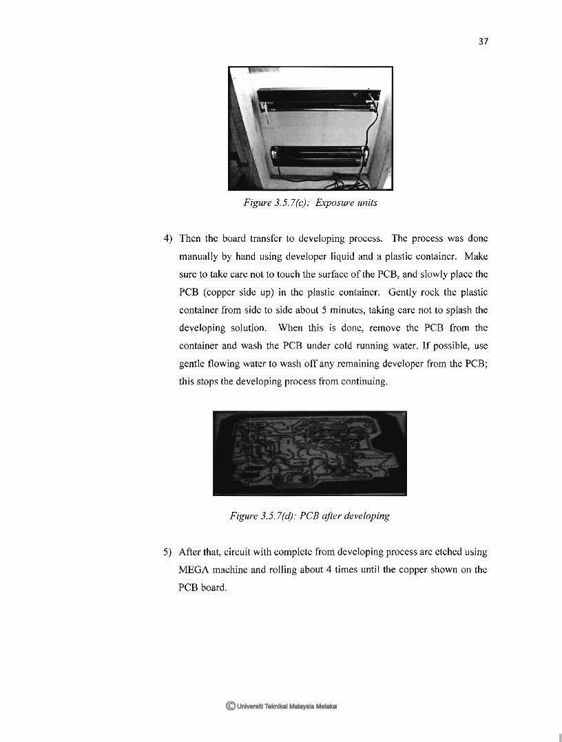
This report is submitted in partial fulfillment of the requirements for the award of the
Bachelor of Electronic Engineering(Electronic Telecommunication) With Honours
Faculty of Electronic and Computer Engineering
Universiti Teknikal Malaysia Melaka
April 2010

UNIVERSTI TEKNIKAL MALAYSIA MELAKA FAKULTI KEJURUTERAAN ELEKTRONIK DAN KEJURUTERAAN KOMPUTER
BORANG PENGESAHAN STATUS LAPORAN
PROJEK SARJANA MUDA II
Tajuk Projek : ………………………………………………………………………………
Sesi
Pengajian :
Saya …………………………………………………………………………………………………..
(HURUF BESAR)
mengaku membenarkan Laporan Projek Sarjana Muda ini disimpan di Perpustakaan dengan syarat-
syarat kegunaan seperti berikut:
1. Laporan adalah hakmilik Universiti Teknikal Malaysia Melaka.
2. Perpustakaan dibenarkan membuat salinan untuk tujuan pengajian sahaja.
3. Perpustakaan dibenarkan membuat salinan laporan ini sebagai bahan pertukaran antara institusi
pengajian tinggi.
4. Sila tandakan ( √ ) :
SULIT*
*(Mengandungi maklumat yang berdarjah keselamatan atau
kepentingan Malaysia seperti yang termaktub di dalam AKTA
RAHSIA RASMI 1972)
TERHAD**
**(Mengandungi maklumat terhad yang telah ditentukan oleh
organisasi/badan di mana penyelidikan dijalankan)
TIDAK TERHAD
Disahkan oleh:
__________________________ ___________________________________
(TANDATANGAN PENULIS) (COP DAN TANDATANGAN PENYELIA)
Tarikh: ……………………….. Tarikh: ………………………..

“I hereby declare that this report is the result of my own except for quotes as cited in the
references”
Signature :
Author : Siti Nadrah Binti Selamat
Date : 30 April 2010

“I hereby declare that I have read this report and in my opinionthis report is sufficient in
terms of the scope and quality for the award of Bachelor of Electronic Engineering
(Telecommunication Electronics) With Honours.”
Signature :
Supervisor‟s Name : Madam Nurmala Irdawaty Bt Hassan
Date : 30 April 2010

ACKNOWLEDGEMENT
All praise be too might ALLAH S.W.T Merciful and Beneficent for the strength and
blessing throughout the entire research and completion of this PSM.
First and foremost, all praise is due to Allah, Lord of the worlds for giving us wellness,
intellect and strength to do this project and also the following individuals. Without them,
it would not be possible for us to complete this project. In particular, I owe a debt of
gratitude to our project supervisor Miss Nurmala Irdawaty bt Hassan for guide, and
giving advice and idea to us complete our project. Without her, this project cannot be
done.
Next, I would like to say a million thanks to my parents for their support and
understanding in allowing me to focus my attention to this project. They have always
been the driving force in pushing us to excel in everything that I do. To our friends, all
of you have been an inspiration to the both of us.
Finally, I would also like to extend our utmost gratitude to all the lecturers of
University Technical Malaysia Malacca (UTeM) for their guidance and patience. Their
teachings have thought me that education and knowledge are vital in life if we wish to
succeed.
Thank you very much.

ABSTRACT
Smart Color Sorting Robot is based on a placing system with some capability to
place the object according to their color. The object will be defined by determining color
of the ball while the system will figure out which location the object should be located.
With the PIC as a controller for the system, a manually feed object which is a coloring
ball will be determined by the robot to take and eject them to their exact location or
station. In this project a line follower will brought the ball that will be sense by LDR
sensor to right station. A main part in this project is an LDR sensor which is used to
detect light. Capability of this system to detect the type of this object and it will be
chosen based on their color. There are four stations in the Color Sorter system that we
made. Each station had their own range of color except for the first station which is the
load and unloading station. The ball will be inserting manually by the user. Then the
LDR sensor will detect what color is the object, after the detection been done, the
decision will be made and the line follower will take the object to the station that been
recognized for it.
ABSTRAK
„Smart Color Sorting Robot‟ adalah sistem yang membolehkan sesebuah robot
berkemampuan untuk menempatkan objek berdasarkan warna yang telah ditentukan.
Objek tersebut akan dikenalpasti melalui warnanya. Sementara itu, sistem ini akan
mengenalpasti tempat di mana objek itu akan ditempatkan. PIC digunakan sebagai
sistem kawalan, objek berwarna akan di masukkan secara manual ke dalam robot dan
sistem tersebut akan menempatkan di mana objek berwarna tersebut patut ditempatkan
mengikut kawasan yang ditetapkan. Projek ini menggunakan system garisan untuk
menbawa bola berwarna ke stesen yang ditetapkan melalui cara dimana pengesan yang
telah di letakkn di robot akan mengesan garisan. Bahagian terpenting dalam projek ini
adalah pengesan cahaya. Kebolehan system ini adalah mengenalpasti objek berdasarkan
warna objek. Terdapat empat stesen di dalam system pengasingan warna ini. Setiap
stesen terdapat jenis warna yang telah ditetapkan bagi robot menempatkan objek kecuali
di stesen mela dan stesen akhir. Objek yang digunakan akan dimasukkan secara manual
oleh pengguna. Kemudian, pengesan cahaya akan mengenalpasti warna objek dan
keputusan akan dibuat apabila robot sampi ke stesen yang ditetapkan dan stesen
seterusnya.
TABLE OF CONTENTS
CHAPTER
TITLE
PAGE
TITLE OF PROJECT
STATUS CONFIRMATION FORM
DECLARATION
ACKNOWLEDGEMENT
ABSTRACT
ABSTRAK
TABLE OF CONTENTS
LIST OF TABLES
LIST OF FIGURES
LIST OF ABBREVIATION
LIST OF APPENDICES
i
ii
iii
v
vi
vii
viii
xi
xii
xiv
xv
I INTRODUCTION
1.1 Project Background
1.2 Objectives
1.3 Scope Work
1.4 Problem Statemant
1.5 Significant of Project
1.6 Report Structure
1
1
2
3
3
4
5
II LITERATURE REVIEW
2.1 Application Review
6

2.1.1 Line Follower
2.1.2 Color Sensor
2.1.2.1 Similarity Matching vs.
Thresholding
2.1.2.2 Positioning of Photoresistor
2.2 Controller Review
2.2.1 Microcontroller (PIC16F876A)
2.3 Sensor Review
2.3.1 Infra Red Sensor
2.3.1 Photoresistor (LDR)
2.4 Driver Review
2.4.1 L293D
2.5 Component Review
2.5.1 Servo Motor
2.5.2 Gearbox with DC Motor
2.6 Power Supply
2.7 Electrical Part
2.7.1 DC Motor
6
7
7
8
9
9
11
11
12
12
12
13
14
14
15
16
16
III METHODOLOGY
3.1 Project Methodology
3.2 Explanation of Project Planning
3.2.1 Searching For Project Title
3.2.2 Understanding The Circuit Operation
And Circuit analysis
3.2.3 Preparing For Proposal
3.2.4 Searching For Components
3.2.5 Testing The Circuit Function
3.3 Flow Process of Project
18
18
20
20
20
20
20
21
21

3.3.1 Main Flowchart
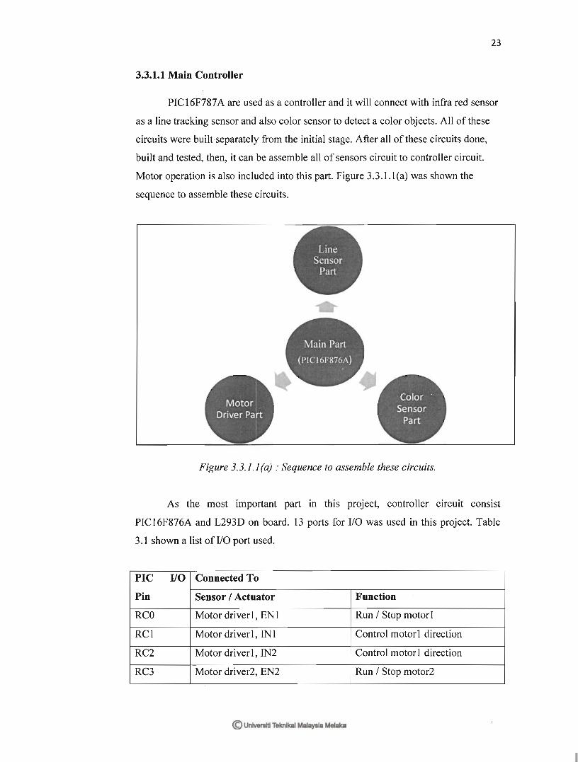
3.3.1.1 Main Controller
3.3.1.2 Sensor Circuit
3.3.1.3 Driver Motor
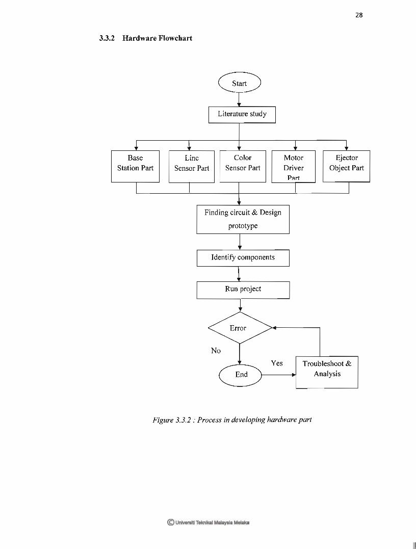
3.3.2 Hardware Flowchart
3.3.3 Software Flowchart
3.4 Printed Circuit Board (PCB) Manufacturing
3.4.1 PCB
3.4.2 Classification of PCB‟s
3.4.3 Types Of The PCB‟s
3.5 PCB Design
3.5.1 Schematic Design
3.5.2 Schematic
3.5.3 Layout Design
3.5.4 The Printed Circuit Board Layout (PCB)
3.5.4.1 Method To Make The Layout
3.5.5 PCB Fabrication
3.5.6 Component Placement And Orientation
3.5.7 Etching Process
3.6 Prepare The PCB For Use And Drill The PCB
3.7 Drilling
3.8 Drilling process
3.9 Soldering Process
3.9.1 Solder onto a PCB
3.10 Testing and Troubleshooting The Circuit
Function
3.11 Designing a Body Structure
3.11.1 Base Body Development
3.11.2 Tower Ball Development
3.11.3 Ejector Development
22
22
23
25
26
28
28
30
31
31
31
32
32
34
34
35
35
35
38
39
39
40
41
42
42
42
43
44
44
IV
V
RESULT AND DISCUSSION
4.1 Result
4.2 Data Analysis and Discussion
4.3 Similarity Matching and Thresholding
CONCLUSIONS AND RECOMMENDATIONS
5.1 Conclusions
5.2 Recommendations
REFERENCE
APPENDICES
45
45
48
51
52
52
53
54
56

TABLES OF TABLES
NO TITLE Page
Table 3.3.1.1 Table of I/O List 24
Table 3.3.1.2 The Operation of The Motor 2 Driver 27
Table 4.2.1
Table 4.2.2
Voltage Reading
Decimal Reading
48
49

LIST OF FIGURES
NO TITLE PAGE
Figure 1.1 Overview of The project Sequence 2
Figure 2.1.1 (a) Simple Closed Loop System 6
Figure 2.1.1 (b) Block Diagram of Line Follower 6
Figure 2.1.2.2 Positioning of Photoresistor 8
Figure 2.2.1 PIC16F876A Pin Diagram 9
Figure 2.3.1 Infra Red Sensor 11
Figure 2.3.2 LDR 12
Figure 2.4.1 (a) L293D 13
Figure 2.4.1 (b) L293D Pin Diagram 13
Figure 2.5.1 Servo Motor 14
Figure 2.5.2 Double Gearbox with DC Motor 15
Figure 2.7 Motor Control Circuit 17
Figure 3.3.1 Flow of Main Process in This Project 22
Figure 3.3.1.1(a) Sequence to assemble These Circuit 23
Figure 3.3.1.1(b) Controller circuit Schematic Diagram 24
Figure 3.3.1.2(a) Voltage Increase with Light 25

Figure 3.3.1.2(b) Voltage Decreases with Light 25
Figure 3.3.1.2(c) Schematic Diagram for LDR 26
Figure 3.3.1.3 Schematic Diagram for L239D 27
Figure 3.3.2 Process in Developing Hardware Part 28
Figure 3.3.3
Figure 3.5.7(a)
Figure 3.5.7(b)
Figure 3.5.7(c)
Figure 3.5.7(d)
Figure 3.5.7(e)
Figure 3.6
Figure 3.8
Figure 3.9.1
Process in Developing Software Part
Circuit on Plastic Transparent
Circuit Printed Put onto PCB Board
Exposure Units
PCB After Developing
PCB Circuit After Come Out from MEGA
Drilled PCB
Drilling Process
Soldered PCB
29
36
36
37
37
38
39
40
42
Figure 3.11.1 Base Body with Controller Circuit 43
Figure 3.11.2
Figure 3.11.3
Tower Ball
Ejector
43
44
Figure 4.1(a) Main Line Sensor 46
Figure 4.1(b) Station Sensor 46
Figure 4.1(c) Robot at Station 1 46
Figure 4.1(d) Press „Run‟ Button to Move 46
Figure 4.1(e) Orange Ball (Station 2) 47
Figure 4.1(f) Red Ball (Station 3) 47
Figure 4.1(g) Green Ball (Station 4) 47

LIST OF APPENDICES
NO TITLE PAGE
A
B
C
D
E
F
G
L293D Datasheet
PIC16F876A Datasheet
Body Structure‟s Design
PCB Layout Design
Technical Drawing
Source Code
Project Planning
54
62
63
64
65
68
79

CHAPTER I
INTRODUCTION
This chapter will briefly discuss on the project overview. The objective, scope, and
thesis outline will be presented in this chapter.
1.1 Project Background
Smart Color Sorting Robot is based on the placing system with some capability
to decide the object according to their color. The object will be defined by determining
color of the ball while the system will figure which location the object should be located.
With the PIC as a controller for the system, a manually feed object which is a coloring
ball will be determined by the robot to take and eject them to their exact location or
station.
In this project a line follower will brought the ball that will be sense by LDR
sensor to right station. A main part in this project is an LDR sensor. Commonly this type
of sensor used to detect light. Other applications are for color sensor, line detector, and
switching element. Capability of this system to detect the type of this object and it will
be chosen based on their color.

There are four stations in the Color Sorter system that we made. Each station had
their own range of color except for the first station which is the load and unloading
station.
The ball will be inserting manually by the user. Then the LDR sensor will detect
what color is the object, after the detection been done, the decision will be made and the
line follower will take the object to the station that been recognized for it.
In this system, there are 4 station;
Station 1 = Load and Unloading station (10 sec delay)
Station 2 = White
Station 3 = Blue
Station 3 = Red
Figure 1.1 Overview of the Project Sequence
1.2 OBJECTIVES
This project is developed with the purposed to optimizing the productivity,
minimizing the cost of the project and make no human mistakes. The main thing of this
2

project is to study how to communicate the programming language with the color
sensor. After that, the line follower system will make its own decision to the station that
been programmed. The objective can be summarized as below:
i. To sort the object according to their color.
ii. To sort the object to the station accordingly.
iii. To make the system run continuously with less rest.
iv. To make an interface between the programming of line follower and the
sensors.
1.3 SCOPE OF PROJECT
This project is subjected to several scope and limitations that are narrowed down
to the study.There are a few scopes and guidelines listed to unsure the project is
conducted within its intended boundary. This is to ensure the project is heading in the
right direction to achieve its intended objectives. The objectives are:
i. Research study on the Programmable Intelligence Computer, PIC16F876A
microcontroller and the control system of the circuit.
ii. To acquire the each sensor that use in this project.
iii. To design circuitry for the overall system
iv. To develop the program that can integrate and control the overall system.
v. To construct the model and test either the robot is function or not.
1.4 PROBLEM STATEMENT
The problems which often occurred in the industrial that can be solve by this
project are:
i. By using this project the company can optimize the productivity.
3

ii. Each company, have their own cost; this project can be minimizing the
cost of the company by minimizing the workers.
iii. Usually, the worker maybe doing some mistakes while doing their job, by
developing this project, the company can decrease the human mistakes.
1.5 SIGNIFICATION OF THE PROJECT
i. Manage to gain more idea and information about the sensor and valve.
ii. Manage to work on the PIC programming
iii. Manage to apply knowledge about the robotic.
iv. Manage to build up the robot.
1.6 REPORT STRUCTURE
Chapter one briefly introduces he overall of the project title Smart Color Sorting
Robot. The introduction consists of overview, objective, problem statement, scope of
work, methodology and structure report.
Meanwhile chapter two discuss about the background of study related to security
system. Literature review will produce overall structure of the Smart Color Sorting
Robot which shows the relationship between project research and theoretical concept.
Chapter three will explain about the project methodology. Project methodology
give details about the method used to solve the problem to complete the project. The
method used such as collecting data method, process and analysis data method,
modelling and etc.
4
Chapter four consists of result and discussion of the project, finding and analysis
throughout the research and project development.
Lastly, chapter five is the project conclusion. This chapter rounds up the attained
achievement of the whole project and reserves suggestions for possible future
researches.
5

CHAPTER II
LITERATURE REVIEW
This chapter is to discuss some fundamental ideas of line follower and color
sensor. The features of this project are also including. All components using for this
project will be explain as well.
2.1 Application Review
In this project, there is two application will be combine. This application is:
1. Line Follower.
2. Color Sensor.
Thus, the research on this application was revealed and a few references found in order
to complete this project.
2.1.1 Line Follower
According to Priyank Patil [1], line follower is a mobile robot that can follow a
path. It can follow path whether the path is straight, corner or at whatever direction. A

line follower will sense a line and maneuvering the line follower to stay right on the line
by using infra red sensor as its „nose‟.
If the line follower tries to move out of track, the infrared sensor will give a
signal to the brain of the robot to stay on line. This situation is made based on the simple
closed loop feedback.
Figure 2.1.1(a): Simple Closed Loop System [1]
R(s) represented as a power supply from 5V and C(s) represented as a direction
of the line follower. A suitable program is needed in order to make this line follower
able to track a line and it‟s supposed to think like a „human‟. The overview of this line
follower is shown as Figure 2.1.1(b).
Figure 2.1.1(b): Block Diagram of Line Follower [1]
6

2.1.2 Color Sensor
According to Society of Robot‟s Article [2], photoresistor cannot see the color of
an object. It only can read the value gain from reflection of the object. The value gain
from a various object is difference. Therefore, some research has been made and the
result seems to be that photoresistor can be use as color detection element. There are two
methods in order to differentiate object‟s color.
1. Similarity Matching Method
2. Thresholding Method
2.1.2.1 Similarity Matching vs. Thresholding
In reality the sensor must be calibrate before the sensors before work. This
means the sensor must sense the object, record the readings, and then make a chart using
this data. That way when the robot is doing its thing and senses the same object, it can
compare the similarity of the new reading vs. the calibrating reading.
For example, suppose the robot needs to follow a white line on a grey floor. The
robot would use a microcontroller to sense the analog value from the sensor. During the
calibration phase the robot measured an analog value of 95 for the grey floor, 112 for the
white line, and then stored these values in memory. Now your robot is on the line, and a
sensor reads 108.
Using the shareholding method, add both calibrated numbers and divide by two
to find the average middle number. For example, (95+112)/2 = threshold. Anything
above that threshold would be the white line, and anything under would be the grey
floor. Similarity matching was used to threshold, if there is three or four colors. This
process is to determine how similar each color of the object is to the calibrated value.
7

Staying with white line example, using similarity matching, by using the equation:
abs(new reading - calibrating reading)/calibrated reading * 100 = similarity
if,
grey floor = (108 - 95)/95 * 100 = 13.7% different
white line = (108 - 112)/112 * 100= 3.6% different
compare: white line < grey floor
therefore the sensor sees a white line
This method can be used for any color and any number of colors, given that the
calibration beforehand. Consider calibration as a way of teaching the robot to
differentiate various colors.
2.1.2.2 Positioning of Photoresistor
The photoresistor must be placed in the middle of the LED. It is because a
photoresistor needs all the values from the LED‟s of the same distance in order to
differentiate the object color.
Figure 2.1.2.2: Positioning of Photoresistor [2]
8

2.2 Controller Review
A controller used in this project is a microcontroller PIC16F876A. This is a 28
pins PIC and it is enough since the sensor used is only 13 ports.
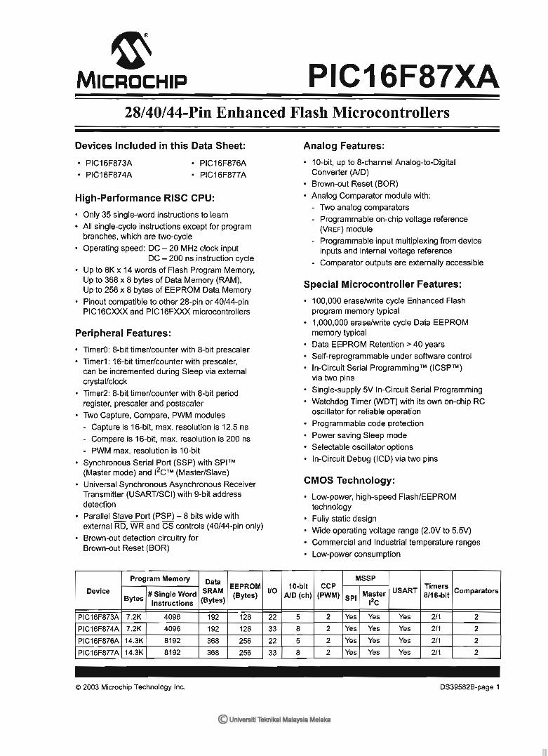
2.2.1 Microcontroller (PIC16F876A)
This microcontroller consist 28 pins, 22 I/O ports. This microcontroller is a high
performance RISC-CPU. The operating speed used for this microcontroller is 20 MHz
clock input. [3]
Figure 2.2.1: PIC16F876A Pin Diagram [3]
Microchip PIC16F876A Microcontroller Features
High-Performance RISC CPU
Operating speed: 20 MHz, 200 ns instruction cycle
Operating voltage: 4.0-5.5V
Industrial temperature range (-40° to +85°C)
14 Interrupt Sources
35 single-word instructions
9
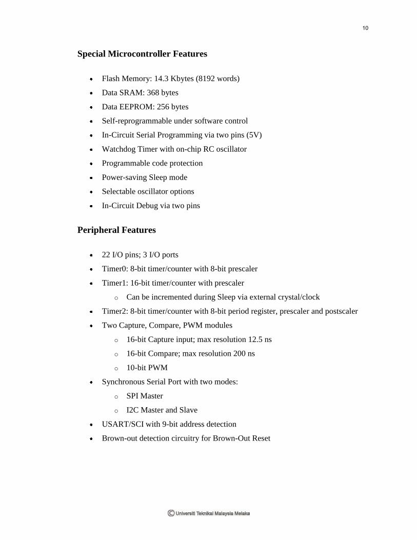
Special Microcontroller Features
Flash Memory: 14.3 Kbytes (8192 words)
Data SRAM: 368 bytes
Data EEPROM: 256 bytes
Self-reprogrammable under software control
In-Circuit Serial Programming via two pins (5V)
Watchdog Timer with on-chip RC oscillator
Programmable code protection
Power-saving Sleep mode
Selectable oscillator options
In-Circuit Debug via two pins
Peripheral Features
22 I/O pins; 3 I/O ports
Timer0: 8-bit timer/counter with 8-bit prescaler
Timer1: 16-bit timer/counter with prescaler
o Can be incremented during Sleep via external crystal/clock
Timer2: 8-bit timer/counter with 8-bit period register, prescaler and postscaler
Two Capture, Compare, PWM modules
o 16-bit Capture input; max resolution 12.5 ns
o 16-bit Compare; max resolution 200 ns
o 10-bit PWM
Synchronous Serial Port with two modes:
o SPI Master
o I2C Master and Slave
USART/SCI with 9-bit address detection
Brown-out detection circuitry for Brown-Out Reset
10

Analog Features
10-bit, 5-channel A/D Converter
Brown-Out Reset
Analog Comparator module
o 2 analog comparators
o Programmable on-chip voltage reference module
o Programmable input multiplexing from device inputs and internal VREF
2.3 Sensors Review
In this project, three infra red sensors has been use to sense a line and one LDR
to detect a ball‟s color.
2.3.1 Infra Red Sensor
Infra red sensor is a „transmit – receive‟ sensor where it is used as a line tracking
sensor of the project. It works when the receiver gain a signal from transmitter. The
transmitter will emit an original signal to the specified surface, thus the original signal
will mix up with surface condition and change. Since the original signal has been
modified, it will read by receiver.
Figure 2.3.1 Infra Red Sensor
11

2.3.2 Photoresistor (LDR)
A LDR (Light Dependent Resistors) sensor is used as a color sensor in the
project. It is able to receive a value in analog signal with a small range provided.
Commonly, this type of sensor used to detect the light. A sensor can be used to measure
the voltage drop across the resistor with the analog port of the microcontroller. An LDR
is a light sensor, is a sensor that resistance is proportional with exposure of light. The
output of this sensor is analog signal. It must be part of the voltage divider circuit in
order to give an output voltage. The voltage supply 6Vdc can be applied to the circuit for
this sensor. Same as other analog sensor, it must be used with comparator to get a digital
signal from this sensor. [4]
Figure 2.3.2: LDR [4]
2.4 Driver Review
L293D is used as a motor driver for the DC motor.
2.4.1 L293D
According to SGS-Thomson [5], L293D motor driver is a dual DC motor driver. It
12

can drive motor with Imax: 600ma, Vmax: 32V. By using this motor driver, user can
eliminate the complicated wiring to drive the two DC motors.
Figure 2.4.1(a) : L293D [5]
Figure 2.4.1(b) : L293D Pin Diagram [5]
This driver is connect to left and right motors and able to enable one or both
motor at a time.
2.5 Component Review
There is a few components that is used in this project.
1. Servo Motor
2. Gearbox with DC Motor
3.
13

2.5.1 Servo Motor
Servo motor is used as an ejector in this project. It will eject the ball from their
position when the robot reaches target station. The servo motor used in the project is
4kg/cm type. Its power supply is from 4.8V to 6V (normally use 5V). Servo motor is
used in the project because it can give accurate angle control e.g. 90 degree, 40 degree.
In addition, it can hold the angle continuously. The servo motor needs an operating
frequency of 40Hz. It can rotate from 0 degree to 180 degree when the pulse duty ration
changed. [6]
Figure 2.5.1: Servo Motor [6]
2.5.2 Gearbox with DC Motor
A double gearbox that operate using DC motor act as an engine of this project.
This gearbox consist two motors, adjustable gear ratio and two wheels. The gear motor
used in the project is double gearbox from Tamiya. The motor set consists of 2 motors.
Left and right motor can operate independently. The gear speed is set to 344:1. The
motor is operated using 6V battery. [7]
14

Figure 2.5.2 : Double Gearbox with DC Motor [7]
2.6 Power Supply
The system support 9V DC power supply (dc battery). A LED power indicator is
used to avoid ensure the polarity and the availability of the adapter power supply. In this
project, a separation of two power supply was to avoid interface and to make the robot
moves without any problems. The parts of the power supply are shown below:
1. Power supply to DC motor (6V)
2. Power supply to Microcontroller (9V)
3. Power supply for Servo Motor (6V)
9V power:
The input voltage of the robot is passes through a voltage regulator (LM7805) to
generate constant 5V output. The generated 5V will be noise filtered by 0.1uF ceramic
capacitor and a 1000uF electrolytic capacitor. The clean 5V output will be supplied to
PIC, switches, IR line sensor. LM7805 is used to regulate voltage in the system and
output 5V DC (max current: 1000mA). It supports input voltage from 7V DC to 18V
DC. The generated 5V will be noise filtered by 0.1uF ceramic capacitor and a 1000uF
electrolytic capacitor. An on/off switch is used to turn on/off the system and a LED (5V,
15

5mA) is used to indicate the system is power on/off. The LED is connected through 1KR
resistor to limit current pass through LED is 5mA.
6V power:
The 6V power only used for L293D motor driver to drive 2 motors forwards,
reverse, stop. Same time the 6V power also supply to servo motor.
2.7 Electrical Parts
In this project, DC motor was used to converting electrical power into
mechanical work.
2.7.1 DC Motor
A DC motor works by converting electric power into mechanical work. This is
accomplished by forcing current through a coil and producing a magnetic field that spins
the motor. The simplest DC motor is a single coil apparatus, used here to discuss the DC
motor theory.
The voltage source forces voltage through the coil via sliding contacts or brushes
that are connected to the DC source. These brushes are found on the end of the coil
wires and make a temporary electrical connection with the voltage source. In this motor,
the brushes will make a connection every 180 degrees and current will then flow through
the coil wires. At 0 degrees, the brushes are in contact with the voltage source and
current is flowing. The current that flows through wire segment C-D interacts with the
magnetic field that is present and the result is an upward force on the segment. The
current that flows through segment A-B has the same interaction, but the force is in the
downward direction. Both forces are of equal magnitude, but in opposing directions
since the direction of current flow in the segments is reversed with respect to the
16

magnetic field. At 180 degrees, the same phenomenon occurs, but segment A-B is
forced up and C-D is forced down. At 90 and 270-degrees, the brushes are not in contact
with the voltage source and no force is produced. In these two positions, the rotational
kinetic energy of the motor keeps it spinning until the brushes regain contact. [8]
Figure 2.7 Motor Control Circuit [8]
17

CHAPTER III
METHODOLOGY
This chapter contains the process of designing Smart Color Sorting Robot which
discusses about the hardware and software development including the hardware design
and software programming. This chapter will explain about the project‟s methodology
that is used in developing the software and hardware for smart window shade. The
methodology of a project is guidelines that will explain about the project path from the
beginning until it is completed. Every selection and action that must be done while
implementing the project must be explains in stages. This methodology is needed to
make sure the project that consists will be developed systematically, smoothly and
successfully in order to obtain better results.
3.1 Project Methodology
Firstly, discuss about the project topic that have been proposed, by surfing the Internet
and search the book to obtain circuits suitable to select the best topic for this project.
This project begins with searching for literature reviews from readability source such as
books and journals. Each project needs suitable strategy on planning, so that this project
can be run smoothly. The most important criteria are the application of this project that
should be identify. As soon as the purpose and function of the project is clear, the
project will be divided into two parts.
For the hardware design, initially the design has to be built. Then the circuit is
designed based on a few references. A few circuits found are studied to make sure all the
information is reliable for the title given. After having enough information, circuit is
design using PROTEL, PROTEUS and MULTISIM software. A simulation for the
circuit was done to make sure the circuit used is corrected. If the simulation shows an
incorrect outcome, the circuit will be redesigned until the correct circuit is obtained.
Labs experiments are also done to verify the overall designed are operation.
After check component list, the components buy from the electronics‟ shop and
get free from the PSM lab. Then, the circuits have been constructing to test the
feasibility of the circuit that obtained from internet or books. After do a construct and
test the circuit at breadboard, troubleshoot the circuit if the circuit cannot work. After
troubleshooting the circuit on breadboard, design the PCB etching is needed. After
process on etching, at the point need put in the leads of component and jumpers then
solder the lead of component at the protoboard.
After all, check the circuit on protoboard can function or not. If not, try
troubleshooting it. Following this, to test the circuit, it will be simulated to detect errors
in the circuitry. If errors are discovered the circuit will be troubles hooted and simulated
once again. Then hardware circuit will be transferred to PCB board and the etching
process will be done. The complete circuit then will be interfaced with the home
appliances. After that, troubleshooting will be done to both circuits until the project
function successfully. A model was build to place the project and easy to use.
When there are no errors, next the software and programming process will be
initiated. One by one the programs are built in the C language and tested. The overall
program is separated into small partitions because it is easier to troubleshoot. If the
hardware design and the software development have no errors and counter no problem
the merging of the hardware design and software development will be done. The
19

combination of both will be tested, simulated and troubles hooted. In the process of
troubleshooting, the project will be analyzed and repaired.
3.2 Explanation of Project Planning
3.21 Searching For Project Title
Firstly, before going any further, a suitable title is needed to make sure it is easy
to construct and follow all the criteria fixed by university. So the title Smart Color
Sorting Robot is proposed. This is because, based on the function of this robot that have
capability to decide the object according to their color and the object will be defined by
determining color of the ball while the system will figure which location the object
should be located. This project is developed with the purposed to optimizing the
productivity, minimizing the cost of the project and make no human mistakes.
3.22 Understanding The Circuit Operation And Circuit Analysis
After a suitable title was chosen, the next step is to do some analysis upon circuit
diagram and understand the circuit operation. This is important to understand the circuit
operation to help us find what is wrong when the circuit is not functioning while testing
it. This project starts by searching for literature reviews from readability source as books
and journals. A few circuits found are studied to make sure all the information is
reliable for the title given. This also can help us explain the circuit operation during the
seminar and presentation in front of the panel.
3.23 Preparing For Proposal
A proposal has to be prepared upon this project to get acceptance whether
20

proceeding with the project or not. This proposal is subject to the criteria that been fixed
by university. If this title is not accepted, another project that follows according to the
criteria has to be found. If the project is accepted, then the project has to be discussed
with the supervisor to get advice and information that related to the project.
3.24 Searching For Components
If the proposal is accepted, it means that the title chosen have follow according to
the criteria that have been fixed by university. Then, it will need us to find the
components for the project. Some types of components are provided at the PSM/PMD
laboratory such as resistors, capacitors, light emitting diode, transistors and pushbutton.
University will prepare RM200 to each student that need to claim for components that
are not provided.
3.25 Testing The Circuit Function
After all of the components have been prepared, then the circuit functions have
to be tested and do simulation on it. Basically, there are two ways of doing simulation
which are by using program or software in computer and simulation on breadboard. For
simulation on computer, Multisim software was chosen to do the simulation according to
the project circuit diagram. Then, a simulation on breadboard has to be done with the
real components. These two types of simulation are different because, by using
multisim, we only know the circuit is functioning as in theory. To prove it in real, a test
it on the breadboard has to be done. This is important to make sure there are no
problems with the components after supply the circuit was supplied with voltage and
current. If the circuit is not functioning during the test or simulation, then we had to
troubleshoot the circuit until it functioning very well. So, during the test on breadboard,
this project was functioning according to the theory.
21


3030

31


CHAPTER IV
RESULT AND DISCUSSION
This chapter will discuss on the result and discussion of this project. The analysis,
calculation and gantt chart will presented in this chapter.
4.1 RESULT
The result of this project is the robot capable to sense the line and move on the
track only. At first, the robot should be manually feed object which is colouring ball at
load and unloading station. When placing the robot, there is three line sensors which are
two of it was located under the body to detect main line as shown in Figure 4.1(a), while
the other line sensor was located at the side of body to identify the station as shown in
Figure 4.1 (b).
The orange LED at left and right of the robot indicated the motor that make the
robot move in a good condition when it ON. Commonly, the infra red sensors have low
stability. To overcome this problem, buffering IC was used to improve the stability of
infra red. The function of heatsink that used is to reduce the heat to make sure all of

component not damaged by heat. Since the robot capable to place three type of color,
relay was used to switch the color.
Figure 4.1(a): Main Line Sensor Figure 4.1(b): Station Sensor
When the robot is ON, there is two LED that locate at the both side of the robot
will be ON as shown in Figure 4.1(c) and the buzzer will buzz to inform the user that the
robot is ready to use. At Station 1 (load and unloading station), the RUN button will be
push to start the robot as shown in Figure 4.1(d). Then, the robot will move according to
the track that readily made.
Figure 4.1(c): Robot at Station 1 Figure 4.1(d): Press “run” button to
move
46

At Station 2, the robot must eject Orange Ball as shown in Figure 4.1(e). When
the station sensor detects station, the robot will stop. Then, the color sensor will make
confirmation whether the ball is correct which is orange ball. Next, the robot will move
on to the next station. At Station 3, the robot must eject Red Ball as shown in Figure
4.1(f) while at Station 4, the robot should eject Green Ball as shown in Figure 4.1(g). At
every station the process for each station are the same with process at Station 2.
Figure 4.1(e): Orange ball Figure 4.1(f): Red Ball Figure 4.1(g): Green Ball
(Station 2) (Station 3) (Station4)
At every station, the robot will eject only the color that has been programmed
which is orange color for Station 2, red color for Station 3 and Green color for Station 4.
If the color is incorrect, the robot will detect the station and LED for the station will ON
and the buzzer will buzz. The robot will move to the station of the color object that the
robot carry and it will direct move to home if there is no other ball. If the robots arrive at
home, but there is any object in the tower of robot, the run button must be push to
deliver the object.
This robot capable to carry not only can carry and eject sphere object but it can
carry other shape of object. For example triangle, rectangular and hexagon. The color of
object should be the same of voltage reading that have been programmed.
47

4.2 Data Analysis and Discussion
To set the LED with a suitable ball, voltage reading for each ball color was
measured. Then, the value of the voltage reading was converting to decimal so that easy
to make a comparison between each color. The voltage readings are shown in Table 4.1
below:
Ball Color White LED Red LED Blue LED All LED
Orange 0.54 - 0.69 0.1 - 0.22 2.28 - 2.32 2.67 - 2.7
Red 0.27 – 0.36 0.11 – 0.20 1.82 – 1.84 2.1 – 2.12
Green 0.26 – 0.34 0.04 – 0.11 0.6 – 0.64 0.96 – 1.01
Table 4.2.1 : Voltage reading
Conversion to decimal
X = 27.54≈27
Above is the example on how to calculate decimal reading. X represents decimal
value while n represents number of bits. PIC 16877 using 28 pin and input 0-5V,
hence the bit is 8.
48

The decimal reading is shown in Table 4.2.1 below:
Ball Color White LED Red LED Blue LED All LED
Orange 27 - 35 5 – 11 116 - 118 136 - 137
Red 13 - 18 5 – 10 92 - 93 107 – 108
Green 13 - 17 2 - 5 30 - 32 48 – 51
Table 4.2.2 : Decimal reading
From the value of the decimal reading, hence, the LED was select as
i. Orange Ball = Red LED
ii. Red Ball = Blue LED
iii. Green Ball = White LED
4.3 Similarity Matching and Thresholding
In reality, sensor must be calibrated. This means the sensor should be test to
sense the object. Then, the readings are recorded and charts are prepared based on the
data. Therefore, when the robot senses the same object, it can compare the similarity of
the new reading with the calibrating reading.
For example, suppose the robot needs to follow a white line on a grey floor. The
robot would use a microcontroller to sense the analog value from the sensor. During the
calibration phase the robot measured an analog value of 95 for the grey floor, 112 for the
white line, and then stored these values in memory. Now the robot is on the line, and a
sensor reads 108.
Using the shareholding method, the both value was add and divide by two to find
the average middle number. For example:
49

= threshold
Anything above that threshold would be the white line, and anything under
would be the grey floor. The robot could make a comparison on which line it should
follow.
50

CHAPTER V
CONCLUSIONS
This chapter will include the conclusion of this project
5.1 Conclusions
Nowadays, industries need a lot of development in order to cut the labor cost and
to maximize the productivity. This project is a new generation of combination between
the line follower and the color sensor system by using PIC interface as the main
controller in order to achieve the industrial needs.
There is some issues being consider in order to making this project successful
and become the most illegible prototype. As refer to the reference and feedback from the
industries, a new version of Smart Color Sorting Robot is created.
The goal of the project is to sort the object due to their color. The object by mean
in our project is coloring ball. By using the PIC compiler, the compiler will compile C

language file to hexadecimal file. There are a few main parts of this project; line
follower, color sensor, and the most important here, capability of this system to detect
the object and it will be chosen based on their color
In conclusions, after all the project is success the robot should be able to sort the
ball according to their color and the station accordingly. The system should be run
continuously with restless and be able to operate based on the project that have been
programmed.
5.2 Recommendations
This project physically functions as a line follower robot that uses to place an
object at the correct station. In future in order to upgrade the capability of this project,
here is some suggestion:
1. The robot capable to sort more color of the object to be placed at the station.
2. The robot has to use a long-time life so that the robot could be use efficiently.
3. The robot could switch the ball by itself when the objects in the robot that have
been inserting manually are not incorrect order.
4. The robot to carry and eject that heavier object.
52

REFERENCES
[1] Priyank Patil, K.J Somaiya College Of Engineering, Line Following Robot.
[2] Society of Robot‟s Article,
http://www.societyofrobots.com/sensors/sensor_color.shtml
[3] Datasheet Article,
http://www.datasheetcatalog.com/datasheets_pdf/P/I/C/1/PIC16F876A.shtml
[4] Society of Robot‟s Article,
http://www.societyofrobots.com/schematics_photoresistor.shtml
[5] SGS-Thomson Microelectronics, L293D Datasheet.
http://search.datasheetcatalog.net/key/L293D
[6] Servo Motor Article,
http://people.ee.duke.edu/~cec/final/node59.html
[7] Gear Motor Article,
http://www.pololu.com/catalog/product/61
53
[8] Society of Robot‟s Article,
http://www.societyofrobots.com/schematics_dcmotorbraking.shtml
[9] William Schweber. Electronic Communication System, 3rd
edition. Prentice
Hall. 1999. 449-481.
54

APPENDIX A

L293DL293DD
PUSH-PULL FOUR CHANNEL DRIVER WITH DIODES
600mA OUTPUT CURRENT CAPABILITYPER CHANNEL 1.2A PEAK OUTPUT CURRENT (non repeti-tive) PER CHANNELENABLE FACILITY OVERTEMPERATURE PROTECTION LOGICAL "0" INPUT VOLTAGE UP TO 1.5 V(HIGH NOISE IMMUNITY)INTERNAL CLAMP DIODES
DESCRIPTIONThe Device is a monolithic integrated high volt-age, high current four channel driver designed toaccept standard DTL or TTL logic levels and driveinductive loads (such as relays solenoides, DCand stepping motors) and switching power tran-sistors.To simplify use as two bridges each pair of chan-nels is equipped with an enable input. A separatesupply input is provided for the logic, allowing op-eration at a lower voltage and internal clamp di-odes are included.This device is suitable for use in switching appli-cations at frequencies up to 5 kHz.
The L293D is assembled in a 16 lead plasticpackaage which has 4 center pins connected to-gether and used for heatsinkingThe L293DD is assembled in a 20 lead surfacemount which has 8 center pins connected to-gether and used for heatsinking.
June 1996
BLOCK DIAGRAM
SO(12+4+4) Powerdip (12+2+2)
ORDERING NUMBERS:
L293DD L293D
1/7

ABSOLUTE MAXIMUM RATINGS
Symbol Parameter Value Unit
VS Supply Voltage 36 V
VSS Logic Supply Voltage 36 V
Vi Input Voltage 7 V
Ven Enable Voltage 7 V
Io Peak Output Current (100 µs non repetitive) 1.2 A
Ptot Total Power Dissipation at Tpins = 90 °C 4 W
Tstg, Tj Storage and Junction Temperature – 40 to 150 °C
THERMAL DATA
Symbol Decription DIP SO Unit
Rth j-pins Thermal Resistance Junction-pins max. – 14 °C/W
Rth j-amb Thermal Resistance junction-ambient max. 80 50 (*) °C/W
Rth j-case Thermal Resistance Junction-case max. 14 –
(*) With 6sq. cm on board heatsink.
PIN CONNECTIONS (Top view)
SO(12+4+4) Powerdip(12+2+2)
L293D - L293DD
2/7

ELECTRICAL CHARACTERISTICS (for each channel, VS = 24 V, VSS = 5 V, Tamb = 25 °C, unlessotherwise specified)
Symbol Parameter Test Conditions Min. Typ. Max. Unit
VS Supply Voltage (pin 10) VSS 36 V
VSS Logic Supply Voltage (pin 20) 4.5 36 V
IS Total Quiescent Supply Current(pin 10)
Vi = L ; IO = 0 ; Ven = H 2 6 mA
Vi = H ; IO = 0 ; Ven = H 16 24 mA
Ven = L 4 mA
ISS Total Quiescent Logic SupplyCurrent (pin 20)
Vi = L ; IO = 0 ; Ven = H 44 60 mA
Vi = H ; IO = 0 ; Ven = H 16 22 mA
Ven = L 16 24 mA
VIL Input Low Voltage (pin 2, 9, 12,19)
– 0.3 1.5 V
VIH Input High Voltage (pin 2, 9,12, 19)
VSS ≤ 7 V 2.3 VSS V
VSS > 7 V 2.3 7 V
IIL Low Voltage Input Current (pin2, 9, 12, 19)
VIL = 1.5 V – 10 µA
IIH High Voltage Input Current (pin2, 9, 12, 19)
2.3 V ≤ VIH ≤ VSS – 0.6 V 30 100 µA
Ven L Enable Low Voltage(pin 1, 11)
– 0.3 1.5 V
Ven H Enable High Voltage(pin 1, 11)
VSS ≤ 7 V 2.3 VSS V
VSS > 7 V 2.3 7 V
Ien L Low Voltage Enable Current(pin 1, 11)
Ven L = 1.5 V – 30 – 100 µA
Ien H High Voltage Enable Current(pin 1, 11)
2.3 V ≤ Ven H ≤ VSS – 0.6 V ± 10 µA
VCE(sat)H Source Output SaturationVoltage (pins 3, 8, 13, 18)
IO = – 0.6 A 1.4 1.8 V
VCE(sat)L Sink Output Saturation Voltage(pins 3, 8, 13, 18)
IO = + 0.6 A 1.2 1.8 V
VF Clamp Diode Forward Voltage IO = 600nA 1.3 V
tr Rise Time (*) 0.1 to 0.9 VO 250 ns
tf Fall Time (*) 0.9 to 0.1 VO 250 ns
ton Turn-on Delay (*) 0.5 Vi to 0.5 VO 750 ns
toff Turn-off Delay (*) 0.5 Vi to 0.5 VO 200 ns
(*) See fig. 1.
L293D - L293DD
3/7

TRUTH TABLE (one channel)
Input Enable (*) Output
HLHL
HHLL
HLZZ
Z = High output impedance(*) Relative to the considered channel
Figure 1: Switching Times
Figure 2: Junction to ambient thermal resistance vs. area on board heatsink (SO12+4+4 package)
L293D - L293DD
4/7

POWERDIP16 PACKAGE MECHANICAL DATA
DIM.mm inch
MIN. TYP. MAX. MIN. TYP. MAX.
a1 0.51 0.020
B 0.85 1.40 0.033 0.055
b 0.50 0.020
b1 0.38 0.50 0.015 0.020
D 20.0 0.787
E 8.80 0.346
e 2.54 0.100
e3 17.78 0.700
F 7.10 0.280
I 5.10 0.201
L 3.30 0.130
Z 1.27 0.050
L293D - L293DD
5/7

SO20 PACKAGE MECHANICAL DATA
DIM.mm inch
MIN. TYP. MAX. MIN. TYP. MAX.
A 2.65 0.104
a1 0.1 0.2 0.004 0.008
a2 2.45 0.096
b 0.35 0.49 0.014 0.019
b1 0.23 0.32 0.009 0.013
C 0.5 0.020
c1 45 1.772
D 1 12.6 0.039 0.496
E 10 10.65 0.394 0.419
e 1.27 0.050
e3 11.43 0.450
F 1 7.4 0.039 0.291
G 8.8 9.15 0.346 0.360
L 0.5 1.27 0.020 0.050
M 0.75 0.030
S 8° (max.)
L293D - L293DD
6/7
Information furnished is believed to be accurate and reliable. However, SGS-THOMSON Microelectronics assumes no responsibility for theconsequences of use of such information nor for any infringement of patents or other rights of third parties which may result from its use. Nolicense is granted by implication or otherwise under any patent or patent rights of SGS-THOMSON Microelectronics. Specification mentionedin this publication are subject to change without notice. This publication supersedes and replaces all information previously supplied.SGS-THOMSON Microelectronics products are not authorized for use as critical components in life support devices or systems without expresswritten approval of SGS-THOMSON Microelectronics.
© 1996 SGS-THOMSON Microelectronics – Printed in Italy – All Rights ReservedSGS-THOMSON Microelectronics GROUP OF COMPANIES
Australia - Brazil - Canada - China - France - Germany - Hong Kong - Italy - Japan - Korea - Malaysia - Malta - Morocco - The Netherlands -Singapore - Spain - Sweden - Switzerland - Taiwan - Thailand - United Kingdom - U.S.A.
L293D - L293DD
7/7

APPENDIX B


APPENDIX C

Body Structure’s Design
Top View Bottom View
Front View Side View

APPENDIX D


APPENDIX E

Technical Drawing


APPENDIX F

Source Code
; colour ball robot
include "p16F877.inc"
_code_tmp_0000 equ 0x70
_code_tmp_0001 equ 0x71
param00_delay_ms equ 0x72
param00_delay_s equ 0x74
_DELAY1 equ 0x75
_A equ 0x76
_B equ 0x77
_C equ 0x78
_t equ 0x79
_PORTC equ 0x07
_PORTD equ 0x08
_PORTE equ 0x09
_TRISC equ 0x87
_TRISD equ 0x88
_TRISE equ 0x89
_ADCON1 equ 0x9f
ORG 0
clrf PCLATH
goto start__code
_point
goto _point__code
_tscn
goto _tscn__code
_delay_ms
goto _delay_ms__code
_delay_s
goto _delay_s__code
start__code
movlw D'10'
movwf _DELAY1
clrf _t
__CONFIG _CP_OFF & _WDT_OFF & _BODEN_OFF & _PWRTE_ON &
_XT_OSC & _WRT_ENABLE_ON & _LVP_OFF & _CPD_OFF
_main__code
bsf STATUS, RP0
bsf STATUS, RP0
bcf STATUS, RP1
clrf TRISA
movlw D'255'
movwf TRISB
clrf _TRISC
movlw D'7'
movwf _TRISD
movlw D'1'
movwf _TRISE
movlw D'6'
movwf _ADCON1

bcf STATUS, RP0
bcf STATUS, RP0
clrf PORTA
clrf PORTB
clrf _PORTC
clrf _PORTD
clrf _PORTE
bsf _PORTC, D'0'
movlw D'50'
movwf param00_delay_ms
call _delay_ms
bcf PCLATH, 3
bcf PCLATH, 4
bcf STATUS, RP0
bcf STATUS, RP1
bcf _PORTC, D'0'
movlw D'50'
movwf param00_delay_ms
call _delay_ms
bcf PCLATH, 3
bcf PCLATH, 4
bcf STATUS, RP0
bcf STATUS, RP1
bsf _PORTC, D'0'
movlw D'50'
movwf param00_delay_ms
call _delay_ms
bcf PCLATH, 3
bcf PCLATH, 4
bcf STATUS, RP0
bcf STATUS, RP1
bcf _PORTC, D'0'
movlw D'50'
movwf param00_delay_ms
call _delay_ms
bcf PCLATH, 3
bcf PCLATH, 4
bcf STATUS, RP0
bcf STATUS, RP1
bsf _PORTC, D'0'
movlw D'50'
movwf param00_delay_ms
call _delay_ms
bcf PCLATH, 3
bcf PCLATH, 4
bcf STATUS, RP0
bcf STATUS, RP1
bcf _PORTC, D'0'
movlw D'50'
movwf param00_delay_ms
call _delay_ms
bcf PCLATH, 3
bcf PCLATH, 4
movlw D'16'

bcf STATUS, RP0
bcf STATUS, RP1
movwf _PORTC
movlw D'200'
movwf param00_delay_ms
call _delay_ms
bcf PCLATH, 3
bcf PCLATH, 4
movlw D'32'
bcf STATUS, RP0
bcf STATUS, RP1
movwf _PORTC
movlw D'200'
movwf param00_delay_ms
call _delay_ms
bcf PCLATH, 3
bcf PCLATH, 4
movlw D'64'
bcf STATUS, RP0
bcf STATUS, RP1
movwf _PORTC
movlw D'200'
movwf param00_delay_ms
call _delay_ms
bcf PCLATH, 3
bcf PCLATH, 4
movlw D'128'
bcf STATUS, RP0
bcf STATUS, RP1
movwf _PORTC
movlw D'200'
movwf param00_delay_ms
call _delay_ms
bcf PCLATH, 3
bcf PCLATH, 4
movlw D'240'
bcf STATUS, RP0
bcf STATUS, RP1
movwf _PORTC
movlw D'200'
movwf param00_delay_ms
call _delay_ms
bcf PCLATH, 3
bcf PCLATH, 4
bcf STATUS, RP0
bcf STATUS, RP1
clrf _PORTC
movlw D'200'
movwf param00_delay_ms
call _delay_ms
bcf PCLATH, 3
bcf PCLATH, 4
movlw D'240'
bcf STATUS, RP0
bcf STATUS, RP1
movwf _PORTC
movlw D'200'
movwf param00_delay_ms
call _delay_ms
bcf PCLATH, 3
bcf PCLATH, 4
bcf STATUS, RP0
bcf STATUS, RP1
clrf _PORTC
movlw D'200'
movwf param00_delay_ms
call _delay_ms
bcf PCLATH, 3
bcf PCLATH, 4
movlw D'240'
bcf STATUS, RP0
bcf STATUS, RP1
movwf _PORTC
movlw D'200'
movwf param00_delay_ms
call _delay_ms
bcf PCLATH, 3
bcf PCLATH, 4
bcf STATUS, RP0
bcf STATUS, RP1
clrf _PORTC
movlw D'200'
movwf param00_delay_ms
call _delay_ms
bcf PCLATH, 3
bcf PCLATH, 4
bcf STATUS, RP0
bcf STATUS, RP1
bsf _PORTC, D'0'
movlw D'50'
movwf param00_delay_ms
call _delay_ms
bcf PCLATH, 3
bcf PCLATH, 4
bcf STATUS, RP0
bcf STATUS, RP1
bcf _PORTC, D'0'
movlw D'50'
movwf param00_delay_ms
call _delay_ms
bcf PCLATH, 3
bcf PCLATH, 4
bcf STATUS, RP0
bcf STATUS, RP1
bsf _PORTC, D'0'
movlw D'50'
movwf param00_delay_ms
call _delay_ms

bcf PCLATH, 3
bcf PCLATH, 4
bcf STATUS, RP0
bcf STATUS, RP1
bcf _PORTC, D'0'
movlw D'50'
movwf param00_delay_ms
call _delay_ms
bcf PCLATH, 3
bcf PCLATH, 4
bcf STATUS, RP0
bcf STATUS, RP1
clrf PORTA
clrf PORTB
clrf _PORTC
clrf _PORTD
clrf _PORTE
_f1
bcf STATUS, RP0
bcf STATUS, RP1
clrf PORTB
clrf _PORTD
movlw D'50'
movwf param00_delay_ms
call _delay_ms
bcf PCLATH, 3
bcf PCLATH, 4
label_0002
movlw D'240'
bcf STATUS, RP0
bcf STATUS, RP1
movwf _PORTC
movlw D'70'
movwf param00_delay_ms
call _delay_ms
bcf PCLATH, 3
bcf PCLATH, 4
bcf STATUS, RP0
bcf STATUS, RP1
clrf _PORTC
movlw D'180'
movwf param00_delay_ms
call _delay_ms
bcf PCLATH, 3
bcf PCLATH, 4
bcf STATUS, RP0
bcf STATUS, RP1
movf _PORTE, W
sublw D'1'
movlw 1
btfss STATUS, Z
clrw
sublw 0
btfsc STATUS, Z

goto label_0004
bsf _PORTC, D'0'
movlw D'50'
movwf param00_delay_ms
call _delay_ms
bcf PCLATH, 3
bcf PCLATH, 4
bcf STATUS, RP0
bcf STATUS, RP1
bcf _PORTC, D'0'
movlw D'50'
movwf param00_delay_ms
call _delay_ms
bcf PCLATH, 3
bcf PCLATH, 4
bcf STATUS, RP0
bcf STATUS, RP1
bsf _PORTC, D'0'
movlw D'50'
movwf param00_delay_ms
call _delay_ms
bcf PCLATH, 3
bcf PCLATH, 4
bcf STATUS, RP0
bcf STATUS, RP1
bcf _PORTC, D'0'
movlw D'50'
movwf param00_delay_ms
call _delay_ms
bcf PCLATH, 3
bcf PCLATH, 4
_RUN
bcf STATUS, RP0
bcf STATUS, RP1
clrf _PORTD
movlw D'20'
movwf param00_delay_ms
call _delay_ms
bcf PCLATH, 3
bcf PCLATH, 4
bcf STATUS, RP0
bcf STATUS, RP1
movf PORTB, W
andlw D'32'
movwf _A
movf PORTB, W
andlw D'64'
movwf _B
movf PORTB, W
andlw D'224'
movwf _C
movf _PORTD, W
sublw D'5'
movlw 1

btfss STATUS, Z
clrw
sublw 0
btfsc STATUS, Z
goto label_0005
movlw D'1'
movwf PORTA
movf _DELAY1, W
movwf param00_delay_ms
call _delay_ms
bcf PCLATH, 3
bcf PCLATH, 4
label_0005
bcf STATUS, RP0
bcf STATUS, RP1
movf _PORTD, W
sublw D'6'
movlw 1
btfss STATUS, Z
clrw
sublw 0
btfsc STATUS, Z
goto label_0006
movlw D'2'
movwf PORTA
movf _DELAY1, W
movwf param00_delay_ms
call _delay_ms
bcf PCLATH, 3
bcf PCLATH, 4
label_0006
bcf STATUS, RP0
bcf STATUS, RP1
movf _PORTD, W
sublw D'7'
movlw 1
btfss STATUS, Z
clrw
sublw 0
btfsc STATUS, Z
goto label_0007
movlw D'3'
movwf PORTA
movf _DELAY1, W
movwf param00_delay_ms
call _delay_ms
bcf PCLATH, 3
bcf PCLATH, 4
label_0007
bcf STATUS, RP0
bcf STATUS, RP1
movf _PORTD, W
sublw D'3'
movlw 1
btfss STATUS, Z
clrw
sublw 0
btfsc STATUS, Z
goto label_0008
clrf _code_tmp_0000
movf _t, W
addlw D'1'
btfsc STATUS, C
incf _code_tmp_0000 , F
movwf _t
bsf _PORTC, D'0'
movlw D'50'
movwf param00_delay_ms
call _delay_ms
bcf PCLATH, 3
bcf PCLATH, 4
bcf STATUS, RP0
bcf STATUS, RP1
bcf _PORTC, D'0'
movlw D'10'
movwf param00_delay_ms
call _delay_ms
bcf PCLATH, 3
bcf PCLATH, 4
call _point
bcf PCLATH, 3
bcf PCLATH, 4
_C1
call _tscn
bcf PCLATH, 3
bcf PCLATH, 4
goto _C1
label_0008
bcf STATUS, RP0
bcf STATUS, RP1
movf _PORTD, W
sublw D'1'
movlw 1
btfss STATUS, Z
clrw
sublw 0
btfsc STATUS, Z
goto label_0009
clrf _code_tmp_0000
movf _t, W
addlw D'1'
btfsc STATUS, C
incf _code_tmp_0000 , F
movwf _t
bsf _PORTC, D'0'
movlw D'50'
movwf param00_delay_ms
call _delay_ms
bcf PCLATH, 3
bcf PCLATH, 4
bcf STATUS, RP0
bcf STATUS, RP1
bcf _PORTC, D'0'
movlw D'10'
movwf param00_delay_ms
call _delay_ms
bcf PCLATH, 3
bcf PCLATH, 4
call _point
bcf PCLATH, 3
bcf PCLATH, 4
_C2
call _tscn
bcf PCLATH, 3
bcf PCLATH, 4
goto _C2
label_0009
bcf STATUS, RP0
bcf STATUS, RP1
movf _PORTD, W
sublw D'2'
movlw 1
btfss STATUS, Z
clrw
sublw 0
btfsc STATUS, Z
goto label_0010
clrf _code_tmp_0000
movf _t, W
addlw D'1'
btfsc STATUS, C
incf _code_tmp_0000 , F
movwf _t
bsf _PORTC, D'0'
movlw D'50'
movwf param00_delay_ms
call _delay_ms
bcf PCLATH, 3
bcf PCLATH, 4
bcf STATUS, RP0
bcf STATUS, RP1
bcf _PORTC, D'0'
movlw D'10'
movwf param00_delay_ms
call _delay_ms
bcf PCLATH, 3
bcf PCLATH, 4
call _point
bcf PCLATH, 3
bcf PCLATH, 4
_C3
call _tscn


![[Thursday, 21 May 1998] 3047 Liquor Licensing Amendment](https://img.dokumen.tips/doc/110x75/623d3cd83212722c740a4c4b/thursday-21-may-1998-3047-liquor-licensing-amendment-.jpg)