Embed Size (px)
Citation preview

Sites Reservoir Project Preliminary Project Description and Alternatives
February 2021

This Preliminary Project Description has been prepared as a preliminary draft document in support of preparing a Revised Draft Environmental Impact Report/Supplemental Draft
Environmental Impact Statement (RDEIR/SDEIS) for the Sites Reservoir Project (Project). The purpose for circulating this document at this time is to facilitate early coordination on initial
approaches currently under consideration by the Authority. Therefore, the content of this document will be subject to continued discussions and modifications, and it may not be included in its entirety in the RDEIR/SDEIS. The Authority is not soliciting comments on this Preliminary
Project Description and formal responses will not be provided for any comments received. As required by CEQA and NEPA, a public review and comment period will be provided upon
publication of the RDEIR/SDEIS, which is currently anticipated to be released in late summer 2021.

Sites Reservoir Project – Preliminary Project Description i February 2021
Predecisional Working Document—For Discussion Purposes Only
Contents Chapter 2 Project Description and Alternatives ............................................................... 2-1
2.1 Alternatives Development Process ............................................................................ 2-1
2.1.1 Evaluated Prior to 2019 ....................................................................................... 2-1
2.1.2 Value Planning Process and Alternatives Post-2019 ........................................... 2-2
2.2 CEQA and NEPA Requirements ............................................................................... 2-3
2.2.1 CEQA Requirements ........................................................................................... 2-3
2.2.2 NEPA Requirements ............................................................................................ 2-4
2.3 Overview of Alternatives ........................................................................................... 2-4
2.4 No Project/Action Alternative ................................................................................. 2-12
2.5 Elements Common to All Action Alternatives ........................................................ 2-13
2.5.1 Facilities Common to All Action Alternatives .................................................. 2-13
2.5.2 Operations and Maintenance Common to All Action Alternatives ................... 2-68
2.5.3 Construction Considerations Common to All Action Alternatives ................... 2-84
2.5.4 Project Commitments and Best Management Practices Common to all Alternatives .................................................................................................................... 2-96
2.5.5 Proposition 1 Benefits Common to All Action Alternatives ............................. 2-97
2.6 Alternative 1 Specific Elements ............................................................................... 2-98
2.6.1 Sites Reservoir and Related Facilities................................................................ 2-99
2.6.2 New and Existing Roadways ............................................................................. 2-99
2.6.3 Operations and Maintenance............................................................................ 2-102
2.7 Alternative 2 Specific Elements ............................................................................. 2-102
2.7.1 Sites Reservoir and Related Facilities.............................................................. 2-103
2.7.2 Conveyance to Sacramento River .................................................................... 2-104
2.7.3 New and Existing Roadways ........................................................................... 2-106
2.7.4 Operations and Maintenance............................................................................ 2-106
2.8 Alternative 3 Specific Elements ............................................................................. 2-107
2.9 References Cited .................................................................................................... 2-108
Sites Reservoir Project – Preliminary Project Description ii February 2021
Predecisional Working Document—For Discussion Purposes Only
List of Tables Table 2-1. Summary of Action Alternatives ................................................................................ 2-5
Table 2-2. Summary of I/O Tower Design Characteristics for All Alternatives ....................... 2-45
Table 2-3. Main Dam, Saddle Dam and Saddle Dike Summary for All Alternatives ............... 2-47
Table 2-4. Sites Project Roads & Purposes Common to all Alternatives .................................. 2-63
Table 2-5. Summary of Project Diversion Criteria .................................................................... 2-71
Table 2-6. Pumping Summary for All Action Alternatives ....................................................... 2-80
Table 2-7. Generating Summary for All Action Alternatives.................................................... 2-80
Table 2-8. General Construction Timing and Sequencing......................................................... 2-89
Table 2-9. Estimated Temporary Construction Power Requirements ....................................... 2-94
Table 2-10. General Reservoir Characteristics of Alternative 1 ................................................ 2-99
Table 2-11. General Reservoir Characteristics of Alternative 2 .............................................. 2-103
List of Figures Figure 2-1. Alternatives 1 and 3 Regulating Reservoirs and Conveyance and Sites Reservoir
Facilities ............................................................................................................................... 2-8
Figure 2-2. Alternatives 1 and 3 Conveyance to Sacramento River Components ....................... 2-9
Figure 2-3. Alternative 2 Regulating Reservoirs and Conveyance and Sites Reservoir Facilities 2-10
Figure 2-4. Alternative 2 Conveyance to Sacramento River Components ................................ 2-11
Figure 2-5. Sacramento River Conveyance Components .......................................................... 2-14
Figure 2-6. Red Bluff Pumping Plant ........................................................................................ 2-16
Figure 2-7. GCID Main Canal Head Gate Structure.................................................................. 2-17
Figure 2-8. GCID System Upgrades .......................................................................................... 2-18
Figure 2-9. GCID System Upgrades Continued ........................................................................ 2-19
Figure 2-10. Terminal Regulating Reservoir Facilities Site Plan .............................................. 2-22
Figure 2-11. TRR Pump Generating Plant Facilities ................................................................. 2-23
Figure 2-12. TRR Electrical Substation ..................................................................................... 2-25
Figure 2-13. TRR Pipelines ....................................................................................................... 2-27
Figure 2-14. Funks Reservoir Facilities Site Plan ..................................................................... 2-28
Figure 2-15. Funks Reservoir Stockpile and Haul Route Plan .................................................. 2-30
Figure 2-16. Funks Pump Generating Plant Facilities ............................................................... 2-32
Sites Reservoir Project – Preliminary Project Description iii February 2021
Predecisional Working Document—For Discussion Purposes Only
Figure 2-17. Conveyance Complex Pipelines ............................................................................ 2-33
Figure 2-18. WAPA Schematic Sketch ..................................................................................... 2-36
Figure 2-19. PG&E Schematic Sketch....................................................................................... 2-37
Figure 2-20. Double-Circuit Source Transmission Poles .......................................................... 2-38
Figure 2-21. Funks to TRR Electrical Interconnection .............................................................. 2-39
Figure 2-22. Administration and Operations Building .............................................................. 2-41
Figure 2-23. Maintenance and Storage Building ....................................................................... 2-42
Figure 2-24. Plan of Inlet/Outlet Works Site ............................................................................. 2-43
Figure 2-25. Profile of Inlet/Outlet Works Site ......................................................................... 2-44
Figure 2-26. Sites Dam Plan ...................................................................................................... 2-48
Figure 2-27. Sites Dam Section ................................................................................................. 2-49
Figure 2-28. Golden Gate Dam Plan.......................................................................................... 2-51
Figure 2-29. Golden Gate Dam Section ..................................................................................... 2-52
Figure 2-30. Saddle Dike Section .............................................................................................. 2-54
Figure 2-31. Saddle Dam 8B Spillway ...................................................................................... 2-55
Figure 2-32. TC Canal Intake Site Plan ..................................................................................... 2-57
Figure 2-33. Dunnigan CBD Discharge Site Plan ..................................................................... 2-59
Figure 2-34. Recreation Areas ................................................................................................... 2-60
Figure 2-35. Alternatives 1, 2, and 3 Road Site Map ................................................................ 2-62
Figure 2-36. Available Diversion Capacity versus Streamflow at RBPP .................................. 2-73
Figure 2-37. Available Diversion Capacity versus Streamflow at the Hamilton City Pump Station ............................................................................................................................................ 2-74
Figure 2-38. Onsite Borrow Area Details .................................................................................. 2-92
Figure 2-39. Offsite Aggregate Areas ........................................................................................ 2-93
Figure 2-40. Sites Lodoga Road Realignment and Bridge ...................................................... 2-101
Figure 2-41. Dunnigan Sacramento River Discharge Site Plan ............................................... 2-105
Project Description and Alternatives
Sites Reservoir Project – Preliminary Project Description 2-1 February 2021
Predecisional Working Document—For Discussion Purposes Only
Chapter 2 Project Description and Alternatives
This chapter describes the proposed Sites Reservoir Project (Project) and alternatives analyzed in this Recirculated Draft Environmental Impact Report/Supplemental Draft Environmental Impact Statement (RDEIR/SDEIS). The alternatives were developed in light of the California Environmental Quality Act (CEQA) objectives and the National Environmental Policy Act (NEPA) purpose and need as described in Chapter 1, Introduction. This chapter is supported by Appendices 2A, 2B, 2C, and 2D which provide additional detail on the alternatives screening, construction means and methods and best management practices (BMPs).
2.1 Alternatives Development Process
The range of alternatives evaluated in this RDEIR/SDEIS is the product of an extensive screening process, that has included public input and involvement, occurring over several decades and involving multiple distinct water resource planning efforts. Those planning efforts considered a wide variety of factors, including feasibility and opportunities for reducing significant impacts while meeting applicable program and project objectives and purpose and need. See Appendix 2A, Alternatives Screening and Evaluation, and Appendix 2B, Additional Alternatives Screening and Evaluation, for information on alternatives considered but eliminated and the alternatives that are evaluated in this document.
2.1.1 Evaluated Prior to 2019 Beginning in 1995, the CALFED Bay-Delta Program (CALFED) initiated the evaluation of expanded surface water storage in the Sacramento and San Joaquin Valleys as part of a long-term comprehensive plan to restore the ecological health and improve water management to protect beneficial uses in the Sacramento–San Joaquin Delta (Delta) and the Delta watershed. During preparation of the CALFED Environmental Impact Report/Environmental Impact Statement (EIR/EIS), the CALFED Program initially identified 52 potential surface storage locations and retained 12 reservoir locations statewide for further study. The screening criteria applied indicated a preference for offstream over onstream surface water storage to avoid redirected impacts on aquatic species in the primary tributaries of the Delta.
Following the CALFED Programmatic Record of Decision (CALFED ROD) in 2000, the California Department of Water Resources (DWR) and the Bureau of Reclamation (Reclamation) continued to evaluate potential locations for a reservoir on the western side of the Sacramento Valley as part of the Surface Water Storage Investigation (Reclamation and DWR, 2006). The objectives of this effort were to formulate a project that would enhance water management flexibility in the Sacramento Valley, increase the reliability of water supplies in California, and provide storage and operational benefits to enhance water supply reliability and improve water quality and ecosystems. The results of the analysis identified four potential alternatives: Red Bank (Dippingvat and Schoenfield Reservoirs), Newville Reservoir, Colusa Reservoir, and Sites Reservoir. These four reservoir alternatives were evaluated against
Project Description and Alternatives
Sites Reservoir Project – Preliminary Project Description 2-2 February 2021
Predecisional Working Document—For Discussion Purposes Only
additional screening criteria. This secondary screening conducted after the CALFED ROD found the Sites Reservoir location most able to meet the goals and objectives of the Surface Water Storage Investigation, while minimizing environmental impacts and providing the greatest potential benefits.
The Surface Water Storage Investigation also evaluated a variety of water sources (and associated conveyance options) including diversions from the Colusa Basin Drain (CBD), Sacramento River, and local tributaries. The evaluation process culminated in selection of the existing Tehama-Colusa Canal (TC Canal) and GCID diversion and conveyance facilities in addition to a new pipeline from the Sacramento River near the Moulton Weir (the Delevan Pipeline). These facilities were determined to be the most reliable and capable of meeting the goals and objectives of the study effort conducted after the CALFED ROD.
The 2017 Public Draft Environmental Impact Report/Environmental Impact Statement (2017 Draft EIR/EIS) for the Project evaluated four surface water reservoir size and conveyance options, and another alternative that would not include proposed power generation at the Delevan release structure. All alternatives included a Sites Reservoir to be filled using existing Sacramento River diversion facilities and the new Delevan Pumping Plant on the Sacramento River to allow for diversion and release of flows to the Sacramento River. Associated facilities for all alternatives were similar but varied in location and size. Appendix 2B, Additional Alternatives Screening and Evaluation, provides a more detailed table of differences between the Action Alternatives in this RDEIR/SDEIS and those in the 2017 Draft EIR/EIS.
In August 2017, the Authority submitted a Water Storage Investment Program (WSIP) application to the California Water Commission (CWC) to determine the Project’s eligibility for funding under Proposition 1. The WSIP application evaluated the technical, economic, financial, and environmental feasibility of the Project. The CWC made nine specific determinations, including determining that the Project provides a net ecosystem improvement, provides measurable improvements to the Delta ecosystem, and that the Project would advance the long-term objectives of restoring the ecological health and water management beneficial uses of the Delta. The CWC conditionally approved $816 million in funding for the Project (California Water Commission undated).
2.1.2 Value Planning Process and Alternatives Post-2019 In October 2019, the Authority pursued a value planning process to determine if further refinements to the Project were warranted. Between October 2019 and April 2020, the Authority considered previous input from state and federal agencies, non-governmental organizations, elected officials, landowners, and local communities, and decided to “right size” the Project to better meet the needs of Sites Storage Partners1, the statewide water supply and the environment. Multiple alternatives were considered during the value planning process that took into
1 The governmental agencies, water organizations and others who have funded and received a storage allocation in Sites Reservoir and the resulting water supply or water supply related environmental benefits from the Project. Storage Partners could include local agencies, the State of California, and the Federal Government.
Project Description and Alternatives
Sites Reservoir Project – Preliminary Project Description 2-3 February 2021
Predecisional Working Document—For Discussion Purposes Only
consideration the public and agency comments received on the 2017 Draft EIR/EIS (Sites Project Authority 2020). The primary objectives of this process were to:
• Improve water supply and water supply reliability; • Provide Incremental Level 4 water supply for refuges; • Improve the survival of anadromous fish; and • Enhance the Delta ecosystem.
The secondary objectives of the value planning process were to provide opportunities for flood damage reduction and recreation.
Value planning alternatives combined different types and sizes of diversion, release, reservoir, road, and bridge facilities. The Authority analyzed operational, environmental, and permitting considerations for different alternatives. For example, operational considerations included the ability of several reservoir sizes and conveyance capacities to meet participant subscriptions and participation by the State of California through WSIP. Environmental considerations included reducing the footprints of facilities or eliminating facilities to avoid or minimize impacts and reducing the amount of water diverted to storage. In addition, the Authority evaluated the costs of facilities proposed for each alternative to understand whether each alternative achieved a reasonable cost-per-acre-foot that the Sites Storage Partners could support.
The value planning process identified three recommended alternatives. Alternative Value Planning (VP) 5 involved a 1.3 million-acre-feet (MAF) reservoir and used an existing regulating reservoir (Funks Reservoir) and a new regulating reservoir (the Terminal Regulating Reservoir [TRR]) to fill Sites Reservoir with releases (1,000 cubic feet per second [cfs]) from the southern end of the TC Canal through a pipeline that went to the CBD. Alternative VP 6 was similar to Alternative VP 5, but the releases from the southern end of the TC Canal were conveyed through a pipeline that extended to the Sacramento River. Alternative VP 7 was similar to Alternative VP 5 but included a 1.5-MAF reservoir. The value planning process culminated in a Value Planning Report that was adopted by the Authority in April 2020 (Sites Project Authority 2020). The alternatives in this RDEIR/SDEIS are based on VP 5, VP 6, and VP 7 in the Value Planning Report.
2.2 CEQA and NEPA Requirements
2.2.1 CEQA Requirements The Authority, as the State lead agency, is responsible for the development of alternatives that meet CEQA requirements. Section 15126.6 of the State CEQA Guidelines requires that:
• An EIR shall describe a range of reasonable alternatives to the project, or to the location of the project, which would feasibly attain most of the basic objectives of the project but would avoid or substantially lessen any of the significant effects of the project, and evaluate the comparative merits of the alternatives. An EIR need not consider every conceivable alternative to a project. Rather, it must consider a reasonable range of

Project Description and Alternatives
Sites Reservoir Project – Preliminary Project Description 2-4 February 2021
Predecisional Working Document—For Discussion Purposes Only
potentially feasible alternatives that will foster informed decision-making and public participation. An EIR is not required to consider alternatives which are infeasible.
• The range of potential alternatives to the proposed project shall include those that could feasibly accomplish most of the basic objectives of the project and could avoid or substantially lessen one or more of the significant effects.
• The specific alternative of “no project” shall also be evaluated along with its impact. • The EIR should briefly discuss the rationale for selecting the alternatives to be discussed.
The EIR should also identify any alternatives that were considered by the lead agency but were rejected as infeasible during the scoping process and briefly explain the reasons underlying the lead agency’s determination…. Among the factors that may be used to eliminate alternatives from detailed consideration in an EIR are:
o Failure to meet most of the basic project objectives. o Infeasibility. o Inability to avoid significant environmental impacts.
This RDEIR/SDEIS is prepared in accordance with both NEPA and CEQA, with the Action Alternatives analyzed at an equal level of analysis (consistent with NEPA standards).
2.2.2 NEPA Requirements Reclamation, as the Federal lead agency, is responsible for the development of alternatives that meet NEPA requirements. For the Project alternatives, including the proposed action, NEPA requires that Federal government agencies shall (40 CFR Section 1502.14):
(a) Rigorously explore and objectively evaluate all reasonable alternatives, and for alternatives which were eliminated from detailed study, briefly discuss the reasons for their having been eliminated.
(b) Devote substantial treatment to each alternative considered in detail including the proposed action so that reviewers may evaluate their comparative merits.
(c) Include reasonable alternatives not within the jurisdiction of the lead agency. (d) Include the alternative of no action. (e) Identify the agency's preferred alternative or alternatives, if one or more exists, in the
draft statement and identify such alternative in the final statement unless another law prohibits the expression of such a preference.
(f) Include appropriate mitigation measures not already included in the proposed action or alternatives.
2.3 Overview of Alternatives
The Project would utilize existing infrastructure to divert unregulated and unappropriated flow from the Sacramento River at Red Bluff and Hamilton City and convey water to a new off-
Project Description and Alternatives
Sites Reservoir Project – Preliminary Project Description 2-5 February 2021
Predecisional Working Document—For Discussion Purposes Only
stream reservoir west of Maxwell, California. New and existing facilities would move water into and out of the reservoir, with ultimate release back to the Sacramento River system via existing canals and a new pipeline located near Dunnigan. Construction of the reservoir would necessitate construction of a bridge or bypass road to connect Maxwell with the community of Lodoga. Additional components would include future development of new recreation facilities at the reservoir. This RDEIR/SDEIS presents the No Project Alternative and three Action Alternatives to implement the Project. Project alternatives include:
• No Project Alternative • Alternative 1, 1.5 MAF reservoir, bridge, release to the CBD, and a range of Reclamation
investment up to 7 percent of the Project costs • Alternative 2, 1.3 MAF reservoir, South Road, partial release to the CBD and Sacramento
River, and no Reclamation investment • Alternative 3, 1.5 MAF reservoir, bridge, release to the CBD, and Reclamation
investment up to 25 percent of the Project costs
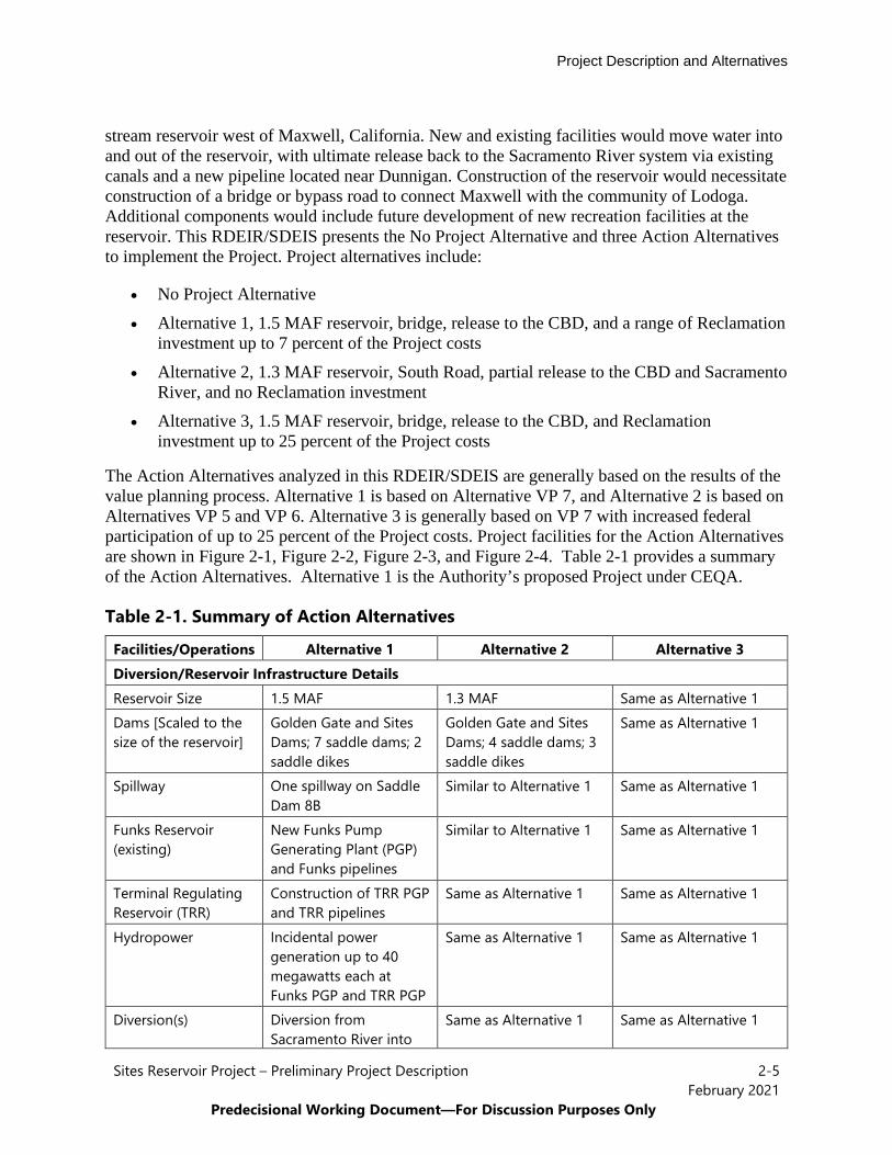
The Action Alternatives analyzed in this RDEIR/SDEIS are generally based on the results of the value planning process. Alternative 1 is based on Alternative VP 7, and Alternative 2 is based on Alternatives VP 5 and VP 6. Alternative 3 is generally based on VP 7 with increased federal participation of up to 25 percent of the Project costs. Project facilities for the Action Alternatives are shown in Figure 2-1, Figure 2-2, Figure 2-3, and Figure 2-4. Table 2-1 provides a summary of the Action Alternatives. Alternative 1 is the Authority’s proposed Project under CEQA.
Table 2-1. Summary of Action Alternatives
Facilities/Operations Alternative 1 Alternative 2 Alternative 3 Diversion/Reservoir Infrastructure Details Reservoir Size 1.5 MAF 1.3 MAF Same as Alternative 1 Dams [Scaled to the size of the reservoir]
Golden Gate and Sites Dams; 7 saddle dams; 2 saddle dikes
Golden Gate and Sites Dams; 4 saddle dams; 3 saddle dikes
Same as Alternative 1
Spillway One spillway on Saddle Dam 8B
Similar to Alternative 1 Same as Alternative 1
Funks Reservoir (existing)
New Funks Pump Generating Plant (PGP) and Funks pipelines
Similar to Alternative 1 Same as Alternative 1
Terminal Regulating Reservoir (TRR)
Construction of TRR PGP and TRR pipelines
Same as Alternative 1 Same as Alternative 1
Hydropower Incidental power generation up to 40 megawatts each at Funks PGP and TRR PGP
Same as Alternative 1 Same as Alternative 1
Diversion(s) Diversion from Sacramento River into
Same as Alternative 1 Same as Alternative 1

Project Description and Alternatives
Sites Reservoir Project – Preliminary Project Description 2-6 February 2021
Predecisional Working Document—For Discussion Purposes Only
Facilities/Operations Alternative 1 Alternative 2 Alternative 3 existing TC Canal at Red Bluff and the existing GCID Main Canal at Hamilton City
Emergency Release Flow
Releases into Funks Creek and Stone Corral Creek via Inlet/Outlet Works, Sites Dam; structures in Saddle Dams 3 and 5 to release north to Hunters Creek watershed; Release from spillway on Saddle Dam 8B north to Hunters Creek watershed
Similar releases via Inlet/Outlet Works, Sites Dam, and spillway on Saddle Dam 8B; No emergency release structures on Saddle Dams 3 and 5
Same as Alternative 1
Recreation Multiple Facilities Consistent with the Authority’s WSIP Application
Two primary areas with infrastructure: 1. Peninsula Hills
Recreation Area 2. Stone Corral Creek
Recreation Area An additional day-use boat ramp
Same as Alternative 1 Same as Alternative 1
Transportation/Circulation Provide Route to West Side of Reservoir
Permanent bridge crossing the reservoir and relocation of a portion of Huffmaster Road with gravel road to residents at the south end of the reservoir
Paved roadway including the relocated segment of Huffmaster Road and a new South Road on the west side of the reservoir
Same as Alternative 1
Operations Diversion Criteria Bypass flows; Pulse flow
protection measure to be applied
Same as Alternative 1 Same as Alternative 1
Reclamation Involvement
1. Funding Partner (up to 7% investment) with operational exchanges; or,
2. Operational Exchanges Only
Operational Exchanges Only a. Within Year
Exchanges b. Real-time
Exchanges
Funding Partner, up to 25% investment, and Operational Exchanges: a. Within Year
Exchanges b. Real-time Exchanges
Project Description and Alternatives
Sites Reservoir Project – Preliminary Project Description 2-7 February 2021
Predecisional Working Document—For Discussion Purposes Only
Facilities/Operations Alternative 1 Alternative 2 Alternative 3 a. Within Year
Exchanges b. Real-time
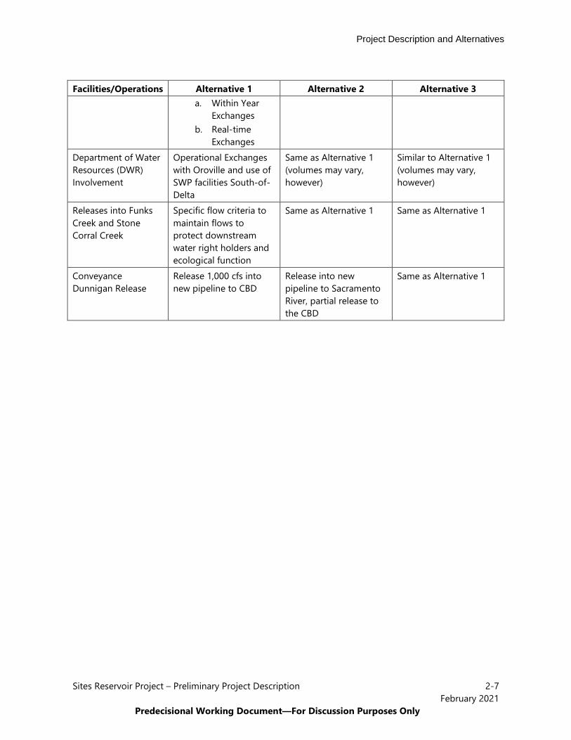
Exchanges Department of Water Resources (DWR) Involvement
Operational Exchanges with Oroville and use of SWP facilities South-of-Delta
Same as Alternative 1 (volumes may vary, however)
Similar to Alternative 1 (volumes may vary, however)
Releases into Funks Creek and Stone Corral Creek
Specific flow criteria to maintain flows to protect downstream water right holders and ecological function
Same as Alternative 1 Same as Alternative 1
Conveyance Dunnigan Release
Release 1,000 cfs into new pipeline to CBD
Release into new pipeline to Sacramento River, partial release to the CBD
Same as Alternative 1

Project Description and Alternatives
Sites Reservoir Project – Preliminary Project Description 2-8 February 2021
Predecisional Working Document—For Discussion Purposes Only
Figure 2-1. Alternatives 1 and 3 Regulating Reservoirs and Conveyance and Sites Reservoir Facilities
Project Description and Alternatives
Sites Reservoir Project – Preliminary Project Description 2-9 February 2021
Predecisional Working Document—For Discussion Purposes Only
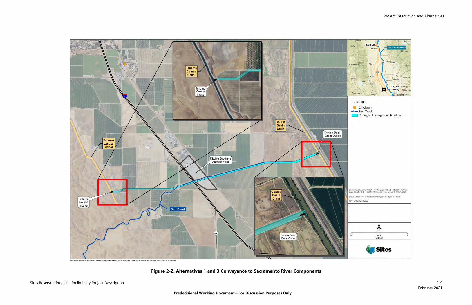
Figure 2-2. Alternatives 1 and 3 Conveyance to Sacramento River Components

Project Description and Alternatives
Sites Reservoir Project – Preliminary Project Description 2-10 February 2021
Predecisional Working Document—For Discussion Purposes Only
Figure 2-3. Alternative 2 Regulating Reservoirs and Conveyance and Sites Reservoir Facilities

Project Description and Alternatives
Sites Reservoir Project – Preliminary Project Description 2-11 February 2021
Predecisional Working Document—For Discussion Purposes Only
Figure 2-4. Alternative 2 Conveyance to Sacramento River Components
Project Description and Alternatives
Sites Reservoir Project – Preliminary Project Description 2-12 February 2021
Predecisional Working Document—For Discussion Purposes Only
It should be noted that the Authority could decide to approve a version of Alternative 2 (with a 1.3-MAF reservoir) that incorporates the bridge component of Alternative 1, or the CBD release component of Alternative 1 instead of release to the Sacramento River, or both of these distinct components. Similarly, the Authority could decide to approve a version of Alternative 1 (with a 1.5-MAF reservoir), or a version of Alternative 3, that incorporates the roadway improvements without the bridge as contemplated by Alternative 2, or the Sacramento River release component of Alternative 2 instead of the CBD release, or both of these distinct components. In this way, the evaluation of Alternatives 1, 2 and 3 actually incorporates a spectrum of multiple options for the decision-makers about the Project facilities and components.
2.4 No Project/Action Alternative
The CEQA Guidelines require that an EIR analyze the No Project Alternative. Evaluation of the No Project Alternative allows decision makers to compare the impacts of approving a proposed project with the impacts of not approving the proposed project. This RDEIR/SDEIS evaluates a No Project Alternative that assumes the Project would not be implemented and considers what would be reasonably expected to occur in the foreseeable future if the Project were not approved, based on current plans and consistent with available infrastructure and community services.
NEPA similarly requires an analysis of an alternative in which the project is not implemented assuming continuation of existing policies and management direction into the future. Under NEPA, the No Action Alternative accounts for reasonably foreseeable changes in existing conditions. Existing conditions includes changes that would reasonably be expected to occur in the foreseeable future if the Project were not approved, based on current plans and consistent with available infrastructure and community services.
For this RDEIR/SDEIS, the term No Project Alternative describes both the No Project Alternative and No Action Alternative for CEQA and NEPA purposes, respectively. Because none of the proposed facilities would be constructed or operated, the No Project Alternative would not materially change conditions as compared to existing conditions. The No Project Alternative assumes the same regulatory criteria as existing conditions. This is because reasonably foreseeable programs and projects included within the No Project Alternative affect water supply, water quality, or anadromous fisheries conditions and are part of existing conditions. For example, the implementation of the 2019 Biological Opinions from the U.S. Fish and Wildlife Service and National Marine Fishery Service for the Reinitiation of Consultation on the Coordinated Operations of the CVP and SWP (ROC on LTO; USFWS 2019 and NMFS 2019) and the Incidental Take Permit for Long-term Operations of the State Water Project in the Sacramento-San Joaquin Delta (SWP ITP; CDFW 2020) are included in both existing conditions and the No Project Alternative.
In addition, DWR’s projected future land use and water use are typically included as fundamental assumptions in the CALSIM II model (see Appendix 1A, Introduction to Appendices and Modeling Information, and Chapter 5, Surface Hydrology Resources, for more information regarding CALSIM) as part of the impact evaluation process. These 2030 water demand conditions indicate that the vast majority of the CVP and SWP water contractors would
Project Description and Alternatives
Sites Reservoir Project – Preliminary Project Description 2-13 February 2021
Predecisional Working Document—For Discussion Purposes Only
use their total contract amounts and that most senior water rights users also would fully use most of their water rights, depending on the hydrologic condition. The Sites Project Authority (Authority) has accepted this assumption for this analysis. This increased demand in addition to the projects currently under construction and those that have received approvals and permits at the time of preparation of the RDEIR/SDEIS constitute the No Project Alternative. Furthermore, the rural nature of the area and limited potential for growth and development in Colusa, Glenn and Yolo Counties within the 2030 study period used for this RDEIR/SDEIS supports similarities between the No Project Alternative and existing conditions.
Under the No Project Alternative, existing conditions outlined in the following resource chapters would not be altered by the Project. However, Project benefits would also not be achieved. Under the No Project Alternative, flood control, ecosystem improvement, and recreation benefits that are part of the Project would not be funded and implemented as part of WSIP. The No Project Alternative would also not provide water supply reliability, operational flexibility, benefits to anadromous fish, water supply for refuges and Delta ecosystem benefits sought with potential Reclamation investment. Finally, the No Project Alternative would eliminate one opportunity to provide a multi-benefit project consistent with the Governor’s Water Resilience Portfolio. The No Project Alternative would not meet the Project objectives and purpose and need stated in Chapter 1 but is analyzed in this RDEIR/SDEIS, consistent with CEQA and NEPA requirements.
2.5 Elements Common to All Action Alternatives
Project facilities, operations and maintenance, construction considerations, commitments and BMPs, and Proposition 1 benefits common to all of the Action Alternatives are described below.
2.5.1 Facilities Common to All Action Alternatives The facilities common to all the Action Alternatives are described below. Design and construction considerations for these facilities are also described. Additional detail for construction means and methods are described in Appendix 2C, Construction Means, Methods, and Assumptions.
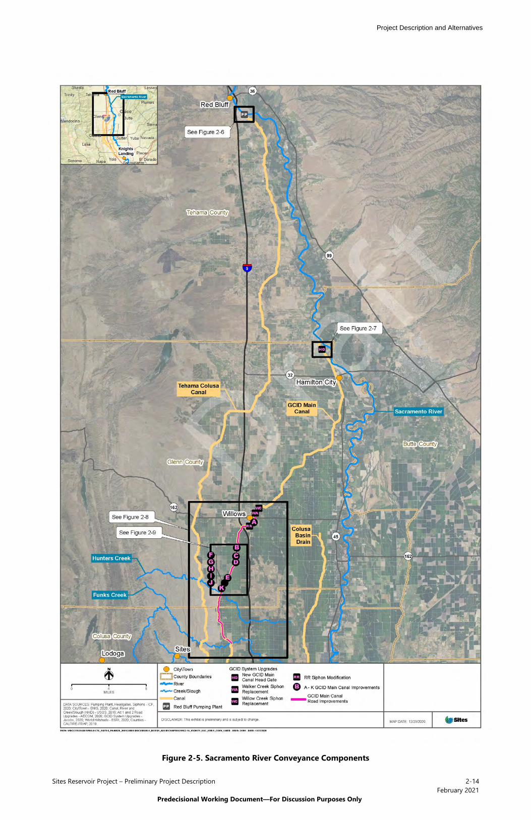
2.5.1.1 Sacramento River Diversion and Conveyance to Regulating Reservoirs All Action Alternatives include the diversion of water from the Sacramento River at the existing RBPP into the existing TC Canal and at the existing Hamilton City Pump Station into the existing GCID Main Canal. The RBPP and TC Canal are owned by Reclamation and operated by the Tehama Colusa Canal Authority. The RBPP has an existing fish screen that meets NMFS and CDFW fish screen criteria. The Hamilton City Pump Station and GCID Main Canal are owned and operated by GCID. The Hamilton City Pump Station has an existing fish screen that meets NMFS and CDFW fish screen criteria. Some improvements would be made to these facilities to allow for Project operations concurrent with these facilities continuing to meet their intended purposes. The location of these improvements is shown in Figure 2-5 and these improvements are described below.
Project Description and Alternatives
Sites Reservoir Project – Preliminary Project Description 2-14February 2021
Predecisional Working Document—For Discussion Purposes Only
Figure 2-5. Sacramento River Conveyance Components
Project Description and Alternatives
Sites Reservoir Project – Preliminary Project Description 2-15February 2021
Predecisional Working Document—For Discussion Purposes Only
Tehama-Colusa Canal Diversion All Action Alternatives include the installation of two additional 250-cfs vertical axial-flow pumps into existing concrete pump bays at the RBPP. The addition of these two pumps would increase the capacity from 2,000 to 2,500 cfs, as well as provide redundancy. See Figure 2-6 for a vicinity map of the RBPP and see Appendix 2C for plan and profile views of the proposed pumps.
The installation of the additional pumps at the RBPP under all of the Action Alternatives would occur at existing facilities and would require limited construction equipment and personnel over a period of approximately 2 months.
GCID Main Canal Diversion and System Upgrades The GCID system may require several different upgrades to support the operation of Sites Reservoir. The specific details of these upgrades would be confirmed during future hydraulic modeling and assessment of conditions. However, for the purposes of this document and the impact analyses contained herein, it is assumed construction would be performed at various locations along the GCID Main Canal, as described below.
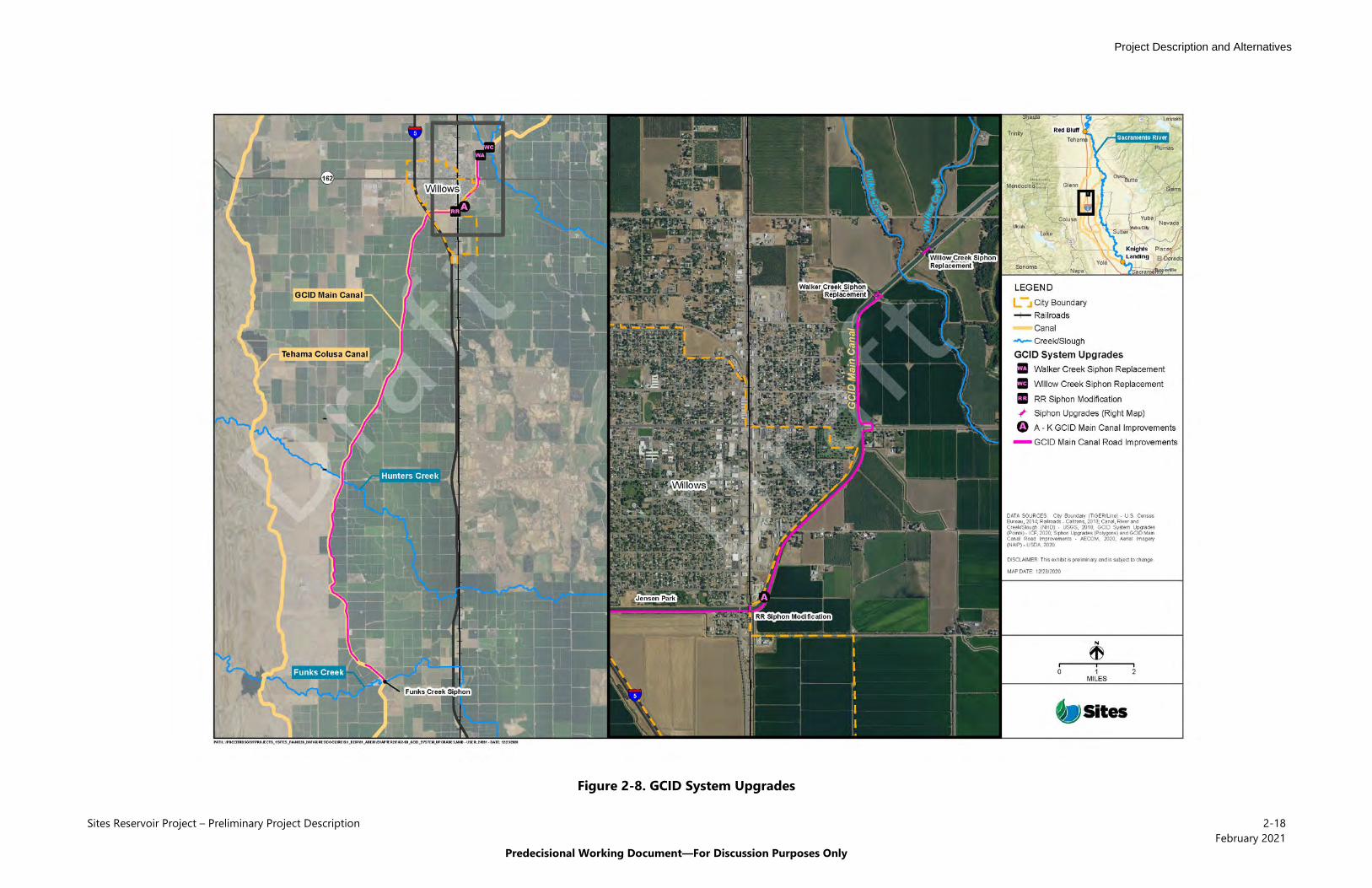
All Action Alternatives would require a new 3,000-cfs Main Canal head gate structure about 0.25 mile downstream of Hamilton City Pump Station (Figure 2-7). This new structure is required because the existing head gate structure would not be adequate for proposed winter operation due to the decrease in water elevation across the structure during high river levels. The existing head gate structure would be left in place to continue to serve as a bridge between County Road 203 and County Road 205 in Glenn County. This structure would continue to operate during construction of the new head gate structure and diversion activities would continue throughout construction. The new head gate structure would be constructed upstream of the existing structure and would include eight automated gates. The water level and flow control functions would involve operating conditions that would result in water surface drops across the head gate of between 3 and 15 feet. The canal reach immediately downstream of the new head gate structure would be lined with concrete for approximately 35 feet to prevent erosion.
GCID typically dewaters their Main Canal for up to 6 weeks each year between early January and late February for maintenance activities. This is the time of year that the Project seeking to utilize the GCID Hamilton City Pump Station and GCID Main Canal to divert and convey under the Project. To reduce this current winter shutdown period from 6 weeks to 2 weeks, other improvements would be required to integrate Sites Reservoir into the GCID system. All Action Alternatives would involve replacing the Walker Creek siphon (MP 24.48) and Willow Creek siphon (MP 24.68) on the Main Canal to allow for increased capacity (Figure 2-8 and Figure 2-9). The siphon under the Union Pacific Railroad (i.e., railroad siphon) at MP 26.6 would beimproved by adding an additional barrel to allow for increased capacity.

Project Description and Alternatives
Sites Reservoir Project – Preliminary Project Description 2-16February 2021
Predecisional Working Document—For Discussion Purposes Only
Figure 2-6. Red Bluff Pumping Plant

Project Description and Alternatives
Sites Reservoir Project – Preliminary Project Description 2-17February 2021
Predecisional Working Document—For Discussion Purposes Only
Figure 2-7. GCID Main Canal Head Gate Structure
Project Description and Alternatives
Sites Reservoir Project – Preliminary Project Description 2-18February 2021
Predecisional Working Document—For Discussion Purposes Only
Figure 2-8. GCID System Upgrades

Project Description and Alternatives
Sites Reservoir Project – Preliminary Project Description 2-19February 2021
Predecisional Working Document—For Discussion Purposes Only
Figure 2-9. GCID System Upgrades Continued

Project Description and Alternatives
Sites Reservoir Project – Preliminary Project Description 2-20February 2021
Predecisional Working Document—For Discussion Purposes Only
All Action Alternatives would entail Main Canal improvements between MP 26 and MP 41.3 to increase the freeboard between Willows and the TRR to a standard 2.5 feet; under existing conditions the freeboard range is 1 to 2 feet. All Action Alternatives would also require road improvements to approximately 17 miles of left bank canal road between the existing Willow Creek siphon and the existing Funks Creek siphon to ensure an all-weather road surface (see Figure 2-8). These road improvements would primarily consist of adding approximately 6 inches of aggregate base material. GCID would manage the facility upgrades using an approach consistent with their existing management practices.
Construction of improvements along with GCID Main Canal would occur in the winter during the regular shutdown period. For the additional siphons on the Main Canal, a portion of the canal around the siphon would be dewatered using an earth coffer dam lined with geomembrane and sump pumps. Using a bore-and-jack procedure a new barrel would be installed, and new headwalls on the upstream and downstream end would be installed to approximately match the existing headwall. Construction staging areas would be in the immediate area of the improvements. The proposed upgrade of the railroad siphon would require coordination and planning with the railroad owners. Construction restrictions may exist regarding minimizing interference with regular railroad operations. To the extent possible, upgrades to the railroad siphon would take place during periods of lowest train traffic, and railroad shutdown time would be minimized.
Earthwork related to the GCID Main Canal to increase the freeboard to 2.5 feet would require a total fill of 5,000 cubic yards. There would be no excavation and only minor reshaping and addition of fill to the sides of the canal. The fill would be sourced from other project spoils and there would be no net import. Construction related to roughly 17 miles of road improvements would require approximately 27,000 cubic yards of aggregate base. It is anticipated the aggregate would be imported from a rock plant within 20 miles of the GCID Main Canal. The GCID improvements along the Main Canal and the existing road would occur within existing rights-of-way and construction would not permanently remove any existing crops.
2.5.1.2 Regulating Reservoirs and Conveyance Complex Multiple facilities would be required to control the conveyance of water between Sites Reservoir and the TC Canal and GCID Main Canal. These facilities would include regulating reservoirs, pipelines, pumping generating plants (PGPs), switchyards, and administration and maintenance buildings. These facilities are described below.
Terminal Regulating Reservoir Pumping from the GCID Main Canal to Sites Reservoir would require construction of the TRR facilities. There would be four primary facilities: the TRR, the TRR PGP, an electrical substation, and TRR pipelines. The TRR facilities would be located in Colusa County north of the GCID Main Canal and west of McDermott Road. The approximately 150-acre site would be accessed by an asphalt concrete paved road off McDermott Road. Paved parking would be provided near the PGP. Asphalt concrete paved roads would provide onsite vehicle access between the TRR PGP and electrical substation, with facility spacing to accommodate an operational crane. The proposed TRR PGP and electrical substation would encompass approximately 7 acres and would be enclosed with security fence with access gates on the south
Project Description and Alternatives
Sites Reservoir Project – Preliminary Project Description 2-21February 2021
Predecisional Working Document—For Discussion Purposes Only
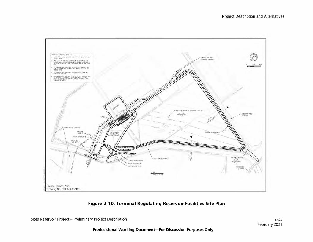
and east sides. See Figure 2-10, Terminal Regulating Reservoir Facilities Site Plan, for the locations of the proposed TRR-related facilities.
The TRR facilities are within a designated Federal Emergency Management Agency (FEMA) Special Flood Hazard Area, Zone A, Without Based Flood Elevation. Site drainage would be conveyed offsite to the existing GCID Main Canal or directly into the TRR through shallow swales or overland flow.
The new TRR would encompass approximately 100 acres immediately east of the GCID Main Canal and have a storage capacity of approximately 600 acre-feet (AF). The TRR would have earthen embankments around its perimeter and an impermeable lining consisting of a geomembrane overlying geocomposite placed over compacted earth. The TRR would be hydraulically connected to the GCID Main Canal to allow water to be conveyed to and from the Sites Reservoir. The TRR would accommodate inflows of up to 1,800 cfs. The GCID Main Canal would be the conveyance source of water for the TRR and its PGP to pump water to Sites Reservoir. The canal would also be the primary conveyance for releases of water from the TRR and its PGP from Sites Reservoir. The spillway for the TRR would be located at the southernmost corner of the reservoir and discharge into Funks Creek.
Access between the east and west sides of the GCID Main Canal adjacent to the TRR would be over a new bridge between the TRR embankment near the gate structures and the west side of the GCID Main Canal. The bridge is anticipated to consist of a pre-cast concrete span between the banks of the GCID Main Canal with concrete abutments founded on piles.
TRR Pumping Generating Plant A TRR PGP would pump water from the TRR to Sites Reservoir; the PGP would include hydroelectric turbines to generate electricity when water was released from Sites Reservoir to the TRR. The PGP would include the following three facilities in five buildings: one pump station, two turbine generator buildings, and two energy dissipating structures (Figure 2-11, TRR Pump Generating Plant Facilities). The pumping plant would have a design capacity of 1,800 cfs, the generating plant 1,000 cfs, and the energy dissipation 1,000 cfs.
Project Description and Alternatives
Sites Reservoir Project – Preliminary Project Description 2-22February 2021
Predecisional Working Document—For Discussion Purposes Only
Figure 2-10. Terminal Regulating Reservoir Facilities Site Plan

Project Description and Alternatives
Sites Reservoir Project – Preliminary Project Description 2-23 February 2021
Predecisional Working Document—For Discussion Purposes Only
Figure 2-11. TRR Pump Generating Plant Facilities

Project Description and Alternatives
Sites Reservoir Project – Preliminary Project Description 2-24 February 2021
Predecisional Working Document—For Discussion Purposes Only
The pump station would support the pumps at the edge of the TRR and be designed to minimize pump vibration. A trashrack would be installed at the front of the wet well to exclude debris. Bulkhead slots would be provided at each wet well to allow bulkheads to be installed and isolate pump bays for maintenance. The pump station would contain 13 pumps in a single row. Six pumps each would feed into two 12-foot-diameter pipes connecting to the turbines (discussed below), and there would be a single standby pump that could feed into either pipe. It is anticipated that all pumps would have a variable frequency drive to adjust to the variable pumping heads while staying within the pump operating range and efficiency.
The two turbine generator buildings would house the turbines, generator, draft tube, associated piping appurtenances, and other electrical equipment. There would be two 13-kilowatt turbines (one for each 12-foot-diameter pipe) that would have a horizontal laying flow pattern. The turbines would discharge water into a draft tube prior to exiting into the TRR. Because the discharge would need to be submerged, the turbines would be in an underground structure with a roof. The aboveground portion of the turbine generator buildings would consist of concrete masonry unit walls.
The two energy dissipation valve structures would allow releases back to the TRR as back-up to the hydroelectric turbine facilities. These structures would each contain a stilling basin and fixed cone valve to dissipate energy before water enters the TRR. There would be a 60-inch fixed cone valve on each of the two 12-foot-diameter pipes for a total of two 60-inch fixed cone valves and a total flow of 1,000 cfs.
TRR Electrical Substation The TRR PGP would require a substation to provide electricity to the associated facilities described above. The electrical substation would connect to existing Pacific Gas and Electric Company (PG&E) or Western Area Power Administration (WAPA) lines. The facility would be constructed on approximately 1.5 acres within the TRR PGP footprint to the north of the TRR. The dimensions of the electrical substation would depend on whether it is connected with PG&E or WAPA lines. The substation would be approximately 460 feet long by 300 feet wide if connected to PG&E lines and be 300 feet long by 240 feet wide if connected to WAPA lines. Figure 2-12, TRR Electrical Substation, provides a plan view of the facility.

Project Description and Alternatives
Sites Reservoir Project – Preliminary Project Description 2-25 February 2021
Predecisional Working Document—For Discussion Purposes Only
Figure 2-12. TRR Electrical Substation
Sites Reservoir Project – Preliminary Project Description 2-26February 2021
Predecisional Working Document—For Discussion Purposes Only
The electrical substation would use electrical equipment that meets the standards of the National Electrical Manufacturers Association, American National Standards Institute, and Institution of Electrical and Electronics Engineers. Additionally, equipment that is listed or labeled as meeting the safety standards or ratings identified by Underwriter Laboratories or a nationally recognized testing laboratory would also be used. The substation design would include primary safety equipment (e.g., circuit breakers, utility-grade relays) and meet the total pumping power requirements or total generation requirements. For more information regarding the pumping power requirements or total generation requirements, please see Section 2.5.2.2, Energy Generation and Energy Use. The substation would have sufficient redundancy such that the failure of any one component would permit the substation to be safely and reliably isolated from the transmission system under fault conditions.
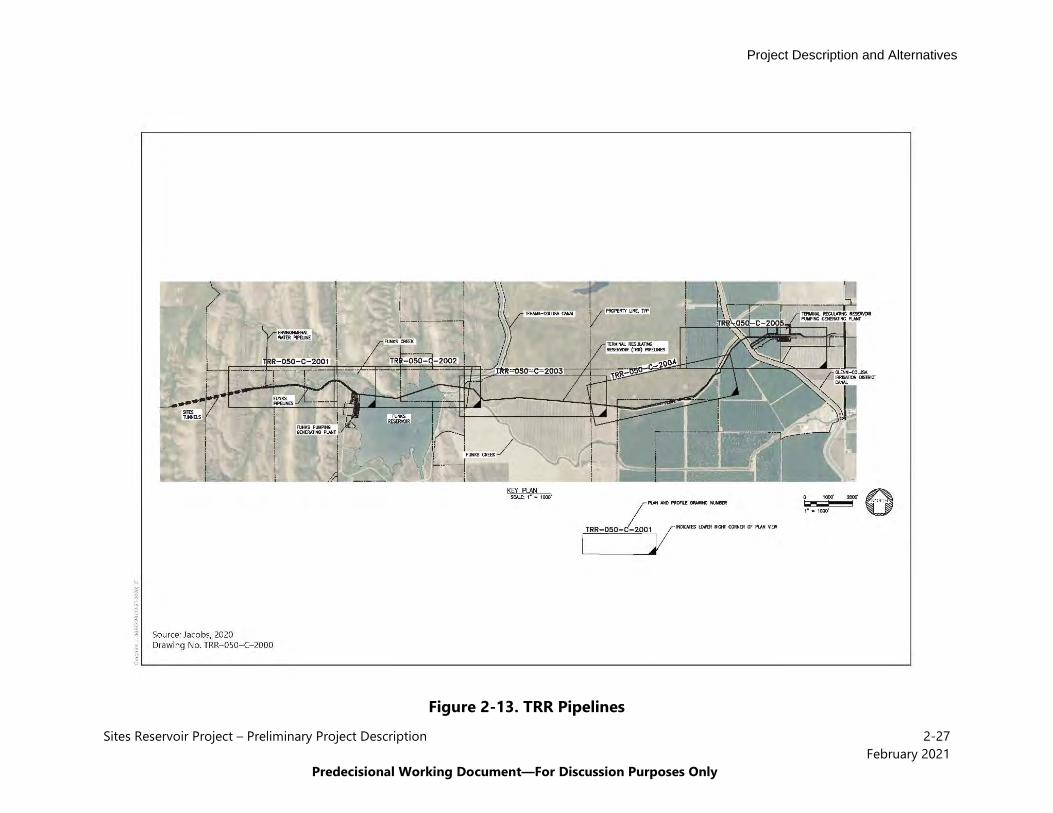
TRR Pipelines Two underground TRR pipelines would convey water approximately 4.5 miles between the TRR PGP and Sites Reservoir. See Figure 2-13, TRR Pipelines, for the location and alignment route of the pipelines. The 12-foot-diameter pipes would extend from the TRR PGP, under Funks Reservoir, and terminate at the transition manifold south of Funks Creek near the Golden Gate Dam. Both TRR pipelines would connect to one of the two side-by-side, 23-foot-inside diameter I/O tunnels at the transition manifold.
The pipelines would parallel the Funks pipelines and Funks Creek and would generally be from 6 feet to 30 feet below ground surface after installation (does not include depth below ground surface where tunneling occurs, which could be up to 100 feet). Trenching for pipelines would include the use of excavators and would be excavated to meet all applicable requirements. Between the TRR and Funks Reservoir, the pipelines would cross the TC Canal using a trenchless method or open cut, depending on construction schedule. East of the TC Canal, the TRR pipelines would run parallel to a drainage canal until they reached the GCID Main Canal where they would cross using a trenchless method or open cut, depending on construction schedule.
Funks Reservoir The existing Funks Reservoir would be used to store and pump water from the TC Canal to and from Sites Reservoir. Excavation of existing accumulated sediment from Funks Reservoir would be required, as would the construction of three facilities: Funks PGP, an electrical substation, and Funks pipelines. These facilities would be constructed in Colusa County, west of the TC Canal, on approximately 7 acres. The overall site would be enclosed by a security fence with access gates on the south and northwest sides. See Figure 2-14, Funks Reservoir Facilities Site Plan, for the location of the facilities.
Project Description and Alternatives
Project Description and Alternatives
Sites Reservoir Project – Preliminary Project Description 2-27February 2021
Predecisional Working Document—For Discussion Purposes Only
Figure 2-13. TRR Pipelines

Project Description and Alternatives
Sites Reservoir Project – Preliminary Project Description 2-28February 2021
Predecisional Working Document—For Discussion Purposes Only
Figure 2-14. Funks Reservoir Facilities Site Plan

Project Description and Alternatives
Sites Reservoir Project – Preliminary Project Description 2-29February 2021
Predecisional Working Document—For Discussion Purposes Only
Access to the Funks Reservoir-related facilities would be provided at the north and south ends of the site. A gravel parking area would be provided near the PGP. Asphalt concrete paved, onsite vehicular access would be provided between the Funks PGP and electrical substation, with facility spacing to accommodate an operational crane. The facilities site would be accessed by an asphalt concrete paved road from Maxwell Sites Road to the south. Existing gravel roads would be improved to be 30 feet wide, with asphalt concrete surfacing for the southern access route, and would be relocated through the site. A gravel bypass road may be provided to the west of the site. On the north side of the facilities site, the existing dirt road would be improved to be a gravel road that would follow the existing road alignment until it reaches the TRR pipeline. At that location, a new access road would be built along the Funks and TRR pipelines to the connection with the I/O tunnels.
The proposed location of the Funks Reservoir-related facilities is in a FEMA Area of Minimal Flood Hazard, Zone X. Onsite drainage would be conveyed offsite directly into Funks Reservoir through shallow swales or overland flow. Offsite stormwater runoff would be collected on the west side of the site in a ditch, conveyed around the site, and deposited into Funks Reservoir.
The existing Funks Reservoir would be used as a source of water to pump to Sites Reservoir and would receive water discharged from the reservoir. The Funks Reservoir operational WSE can only vary slightly from the TC Canal and the reservoir WSE typically ranges from 200 to 205 feet, although the preferred operational WSE range is 202 to 204 feet.
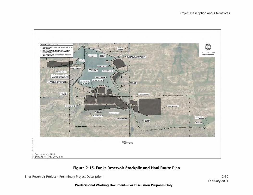
All Action Alternatives would not alter the footprint of Funks Reservoir; however, 740,000 cubic yards of sediment that has accumulated since originally constructed would be excavated from the reservoir. The excavation is anticipated to restore the original capacity of Funks Reservoir. Excavation would proceed to an elevation of approximately 197 feet in the reservoir and 185.5 feet near the Funks PGP on the western side. The bottom of Funks Reservoir would be reshaped to allow large, unimpeded flows to and from the Funks PGP. The excavated sediment would be deposited adjacent to Funks Reservoir as shown on Figure 2-15. For the purposes of this analysis, the sediment is assumed to remain near Funks Reservoir.
Project Description and Alternatives
Sites Reservoir Project – Preliminary Project Description 2-30February 2021
Predecisional Working Document—For Discussion Purposes Only
Figure 2-15. Funks Reservoir Stockpile and Haul Route Plan

Project Description and Alternatives
Sites Reservoir Project – Preliminary Project Description 2-31February 2021
Predecisional Working Document—For Discussion Purposes Only
Funks Pumping Generating Plant The Funks PGP would be used to pump water from Funks Reservoir to Sites Reservoir. The PGP would be constructed on the northwest side of Funks Reservoir. The PGP would include the following three facilities in five buildings: one pump station, two turbine generator buildings, and two energy dissipating structures. An electrical building would also be constructed behind the pumps as part of the pump station. See Figure 2-16, Funks Pump Generating Plant Facilities.
The Funks pump station would be similar to the TRR pump station, except that the orientation of 12-foot-diameter pipelines would be different. The pump station would have a flow rate of 2,100cfs. The turbine generator buildings would be the same as described for the TRR PGP, and eachgenerator would have a design criterion of 1,000 cfs for redundancy. There would be twoturbines, 20-megwatt and 14.5megawatt. Each of the two energy dissipation structures wouldconsist of a single 60-inch fixed cone valve with a design criterion of 1,000 cfs. There would bea 60-inch fixed cone valve on each of the two 12-foot-diameter pipes for a total of two fixedcone valves and a total flow of 2,000 cfs (1,000 cfs each).
Funks Electrical Substation As with the TRR PGP, the Funks PGP would require a substation to provide electricity to the Funks PGP facilities. This substation would connect to either existing WAPA or PG&E lines. The substation would be located west of Funks Reservoir in the footprint of the Funks PGP and would encompass approximately 3 acres. The Funks electrical substation would be similar to the TRR electrical substation; it would be approximately 460 feet long by 300 feet wide if connected to PG&E lines and would be 300 feet long by 240 feet wide if connected to WAPA lines. There is no difference between the Funks substation and the TRR substation. The substation would be designed to accommodate the total pumping power requirements (import) or total generation requirements (export).
Funks Pipelines Two underground Funks pipelines would convey water approximately 1 mile between the Funks PGP and Sites Reservoir. See Figure 2-17, Conveyance Complex Pipelines, for the location and alignment route of the pipelines. The 12-foot-diameter pipes would extend from the Funks Reservoir and Funks PGP and terminate at the transition manifold south of Funks Creek near the Golden Gate Dam. The Funks pipelines generally run parallel to the TRR pipelines. After curving around Funks Creek and hilly areas, the Funks pipelines run south, deviating from the TRR pipeline alignment, to the Funks PGP. Both TRR pipelines would connect to one of the two side-by-side, 23-foot-diameter I/O tunnels at the transition manifold. After installation, the pipelines would generally be from 6 feet to 25 feet below ground surface.

Project Description and Alternatives
Sites Reservoir Project – Preliminary Project Description 2-32February 2021
Predecisional Working Document—For Discussion Purposes Only
Figure 2-16. Funks Pump Generating Plant Facilities

Project Description and Alternatives
Sites Reservoir Project – Preliminary Project Description 2-33February 2021
Predecisional Working Document—For Discussion Purposes Only
Figure 2-17. Conveyance Complex Pipelines

Project Description and Alternatives
Sites Reservoir Project – Preliminary Project Description 2-34February 2021
Predecisional Working Document—For Discussion Purposes Only
Transition Manifold The transition manifold would be constructed at the base of Golden Gate Dam to connect Sites Reservoir to Funks Reservoir and the TRR. The transition manifold would be installed approximately 6 feet below ground and would be approximately 114 feet long by 92 feet wide. The structure would connect the four 12-foot-diameter conveyance pipelines from Funks Reservoir and TRR to two 23-foot-diameter tunnels extending from the Sites Reservoir Inlet/Outlet Works (I/O Works), which are discussed in Section 2.5.1.4, Sites Reservoir and Related Facilities. The transition manifold would have isolation valves to close off the pipelines and allow for maintenance.
In addition to the transition manifold structure, a 12-inch-diameter underground pipeline would extend 2,800 feet north from the manifold to Funks Creek, where it would discharge via an energy-dissipation structure/outlet into the creek. The pressure-reducing valve to dissipate energy before the water is discharged into Funks Creek is necessary because the water pressure would be equal to the Sites Reservoir elevation. The pipeline would be sized to accommodate a range of discharges (zero to 100 cfs) to provide water for the approximately 1.8-mile stretch of Funks Creek below Golden Gate Dam to Funks Reservoir.
Construction of the Transition Manifold would happen after the I/O Tunnels are constructed. Construction means and methods would be similar to that of the TRR Pipelines and Funks Pipelines.
Electrical Transmission Connections New high-voltage transmission lines would be required to provide power to the Funks and TRR PGPs. Transmission lines connecting Funks and TRR substations would also be required. Interconnecting to the existing transmission system would be necessary to provide the electricity needed to operate the large pumps at the TRR and Funks Reservoir. This interconnection would also enable the energy produced at the Funks and TRR PGPs to enter the transmission system during periods of operation that use their respective turbines/generators.
The general laydown areas and construction means and methods of the three substations and high voltage transmission lines that connect either PG&E or WAPA facilities to Sites facilities are provided in Appendix 2C.
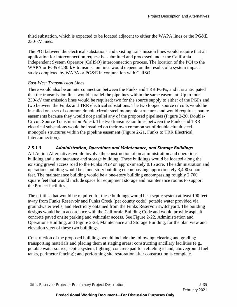
North-South Transmission Connections A new north-south transmission line originating between Funks Reservoir and TRR would connect to WAPA or PG&E existing facilities. Two 230-kilovolt (kV) lines owned and operated by WAPA are located north of Funks Reservoir, and four 230-kV lines owned and operated by PG&E are located west and north of the TRR. WAPA and PG&E are defined as the Transmission Owner and the Transmission Operator of their respective high-voltage transmission lines. Each of these lines is a potential point of interconnection (POI) location; a POI to a high-voltage electric transmission line would be required to provide power. See Figure 2-18, WAPA Schematic Sketch, and Figure 2-19, PG&E Schematic Sketch, for a schematicsketch showing the WAPA and PG&E alternative POI arrangements and the requiredtransmission line lengths to the Funks and TRR electrical substations. The POI would require a
Project Description and Alternatives
Sites Reservoir Project – Preliminary Project Description 2-35February 2021
Predecisional Working Document—For Discussion Purposes Only
third substation, which is expected to be located adjacent to either the WAPA lines or the PG&E 230-kV lines.
The POI between the electrical substations and existing transmission lines would require that an application for interconnection request be submitted and processed under the California Independent System Operator (CalISO) interconnection process. The location of the POI to the WAPA or PG&E 230-kV transmission lines would depend on the results of a system impact study completed by WAPA or PG&E in conjunction with CalISO.
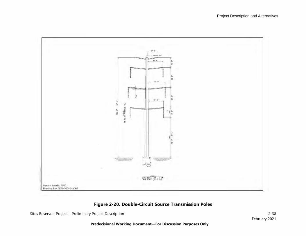
East-West Transmission Lines There would also be an interconnection between the Funks and TRR PGPs, and it is anticipated that the transmission lines would parallel the pipelines within the same easement. Up to four 230-kV transmission lines would be required: two for the source supply to either of the PGPs andtwo between the Funks and TRR electrical substations. The two looped source circuits would beinstalled on a set of common double-circuit steel monopole structures and would require separateeasements because they would not parallel any of the proposed pipelines (Figure 2-20, Double-Circuit Source Transmission Poles). The two transmission lines between the Funks and TRRelectrical substations would be installed on their own common set of double circuit steelmonopole structures within the pipeline easement (Figure 2-21, Funks to TRR ElectricalInterconnection).
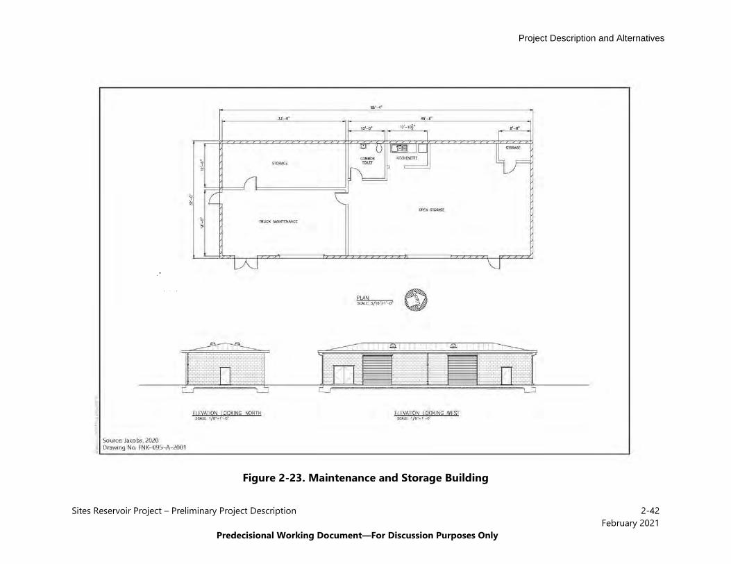
2.5.1.3 Administration, Operations and Maintenance, and Storage Buildings All Action Alternatives would involve the construction of an administration and operations building and a maintenance and storage building. These buildings would be located along the existing gravel access road to the Funks PGP on approximately 0.15 acre. The administration and operations building would be a one-story building encompassing approximately 3,400 square feet. The maintenance building would be a one-story building encompassing roughly 2,700 square feet that would include space for equipment storage and maintenance rooms to support the Project facilities.
The utilities that would be required for these buildings would be a septic system at least 100 feet away from Funks Reservoir and Funks Creek (per county code), potable water provided via groundwater wells, and electricity obtained from the Funks Reservoir switchyard. The building designs would be in accordance with the California Building Code and would provide asphalt concrete paved onsite parking and vehicular access. See Figure 2-22, Administration and Operations Building, and Figure 2-23, Maintenance and Storage Building, for the plan view and elevation view of these two buildings.
Construction of the proposed buildings would include the following: clearing and grading; transporting materials and placing them at staging areas; constructing ancillary facilities (e.g., potable water source, septic system, lighting, concrete pad for refueling island, aboveground fuel tanks, perimeter fencing); and performing site restoration after construction is complete.

Project Description and Alternatives
Sites Reservoir Project – Preliminary Project Description 2-36February 2021
Predecisional Working Document—For Discussion Purposes Only
Figure 2-18. WAPA Schematic Sketch
Project Description and Alternatives
Sites Reservoir Project – Preliminary Project Description 2-37February 2021
Predecisional Working Document—For Discussion Purposes Only
Figure 2-19. PG&E Schematic Sketch
Project Description and Alternatives
Sites Reservoir Project – Preliminary Project Description 2-38February 2021
Predecisional Working Document—For Discussion Purposes Only
Figure 2-20. Double-Circuit Source Transmission Poles

Project Description and Alternatives
Sites Reservoir Project – Preliminary Project Description 2-39February 2021
Predecisional Working Document—For Discussion Purposes Only
Figure 2-21. Funks to TRR Electrical Interconnection
Project Description and Alternatives
Sites Reservoir Project – Preliminary Project Description 2-40February 2021
Predecisional Working Document—For Discussion Purposes Only
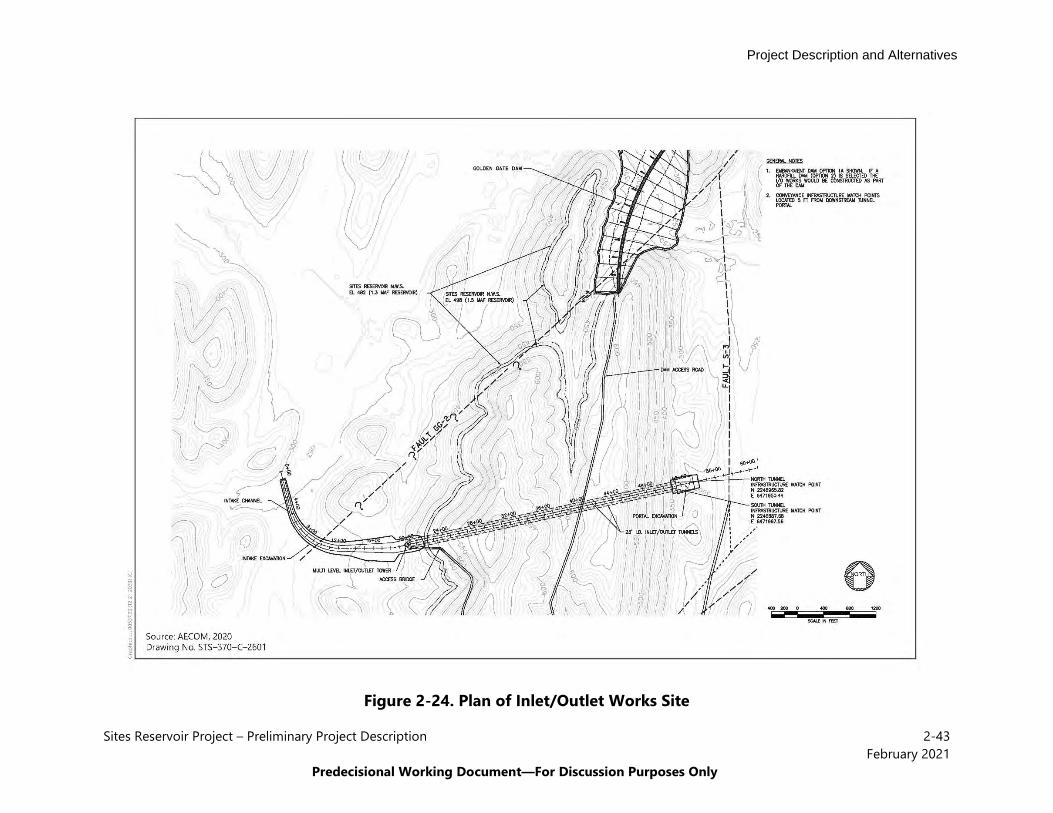
2.5.1.4 Sites Reservoir and Related Facilities Under all Action Alternatives, water would be impounded by the Golden Gate Dam on Funks Creek and the Sites Dam on Stone Corral Creek; a series of saddle dams along the eastern and northern rims of reservoir would close off topographic saddles in the surrounding ridges to form Sites Reservoir. See Figure 2-1 and Figure 2-3 for the location of the Sites Reservoir, Golden Gate Dam, saddle dams, and I/O Works.
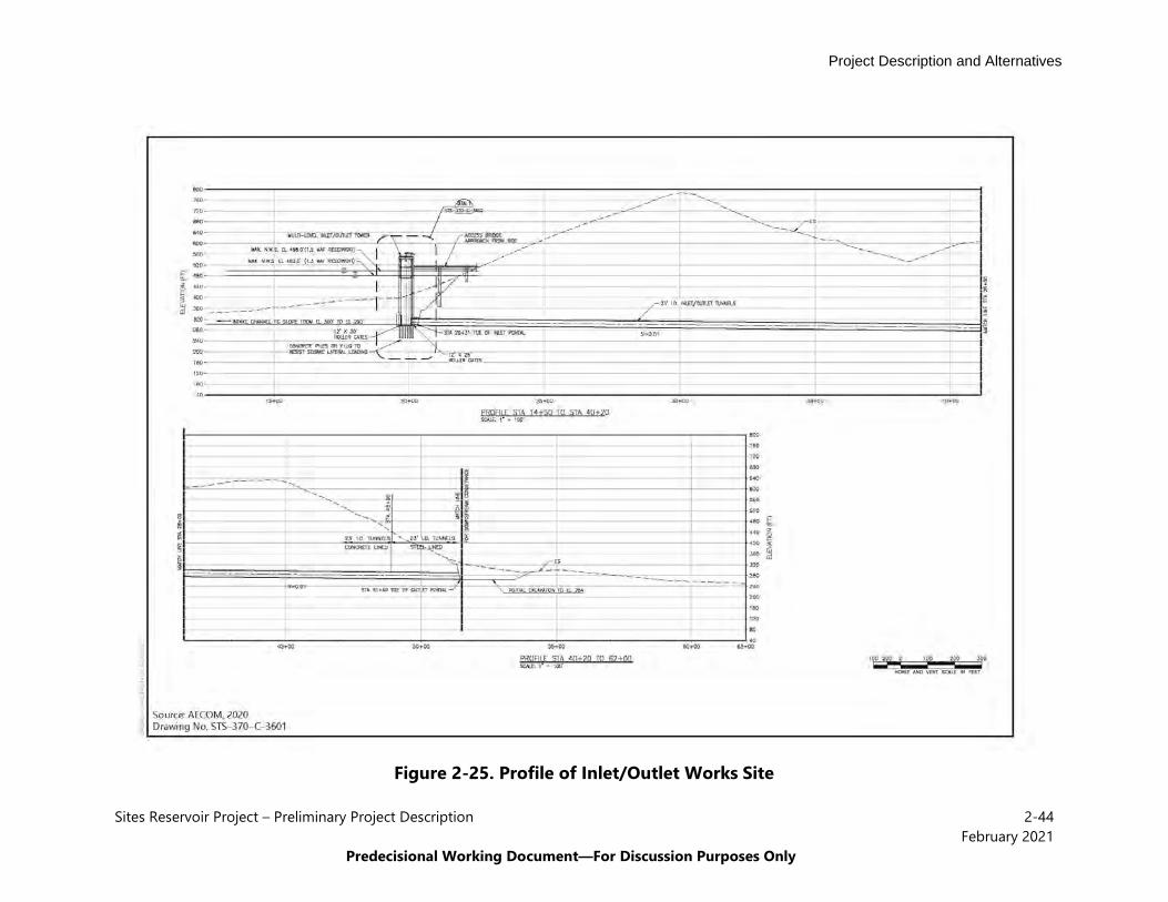
Inlet/Outlet Works The I/O Works for the reservoir are generally located to the south of Golden Gate Dam in Sites Reservoir. See Figure 2-24 (plan) and Figure 2-25 (profile), Inlet/Outlet Works Site, for a plan and profile view of the I/O Works. The I/O Works consists of a low-level intake, multi-level I/O tower, and two I/O tunnels. These structures are described in the subsections below, and Appendix 2C provides the engineering schematics for each structure.
The I/O Works would be designed to meet maximum water supply commitments, as well as safely pass emergency releases per DSOD requirements. The I/O Works would allow a maximum release of 16,000 cfs; the parallel I/O tunnels are designed to each convey half of the emergency drawdown flows (anticipated to be approximately 8,000 cfs each). The I/O Works would meet summer irrigation demands downstream with an estimated maximum release flow of 3,100 cfs. The I/O Works would also allow inflows pumped into the reservoir from the canals; the maximum inflows are anticipated to be 3,900 cfs.
Construction of the I/O Works would disturb approximately 30 acres in the reservoir inundation area and a similarly sized area at the downstream tunnel portal. The construction disturbance would consist of the footprint of the two intakes; tunnel portals; materials, spoils, and equipment staging areas; and access roads. A portion of the footprint outside the reservoir inundation area would overlap with the disturbance area for the conveyance system. Major construction activities associated with the I/O Works would consist of dewatering the construction site with an onsite treatment facility, excavating the hillside for the downstream and upstream tunnel portals, tunneling and hauling tunnel muck to a disposal area, using spoils from the tunnels for Golden Gate Dam or disposing of them in the reservoir inundation area, excavating for the multi-level tower shaft, building the multi-level tower, constructing the access bridge to the multi-level tower, building the low-level intake, and completing finished grading and site clean-up.
The construction of the tunnels that connect the Sites Reservoir to the Funks and TRR pipelines would require excavating the tunnel, installing the tunnel support systems, and controlling groundwater. The I/O tunnels would be constructed using a combination of drill and blast and road header excavation, depending on the strength of the rock, and pre-excavation measures would be used to stabilize the ground and reduce groundwater inflow. As construction proceeded, support systems would be installed and then the reinforced cast-in-place concrete tunnels and steel carrier pipe would be installed.

Project Description and Alternatives
Sites Reservoir Project – Preliminary Project Description 2-41February 2021
Predecisional Working Document—For Discussion Purposes Only
Figure 2-22. Administration and Operations Building
Project Description and Alternatives
Sites Reservoir Project – Preliminary Project Description 2-42February 2021
Predecisional Working Document—For Discussion Purposes Only
Figure 2-23. Maintenance and Storage Building
Project Description and Alternatives
Sites Reservoir Project – Preliminary Project Description 2-43February 2021
Predecisional Working Document—For Discussion Purposes Only
Figure 2-24. Plan of Inlet/Outlet Works Site
Project Description and Alternatives
Sites Reservoir Project – Preliminary Project Description 2-44February 2021
Predecisional Working Document—For Discussion Purposes Only
Figure 2-25. Profile of Inlet/Outlet Works Site
Project Description and Alternatives
Sites Reservoir Project – Preliminary Project Description 2-45February 2021
Predecisional Working Document—For Discussion Purposes Only
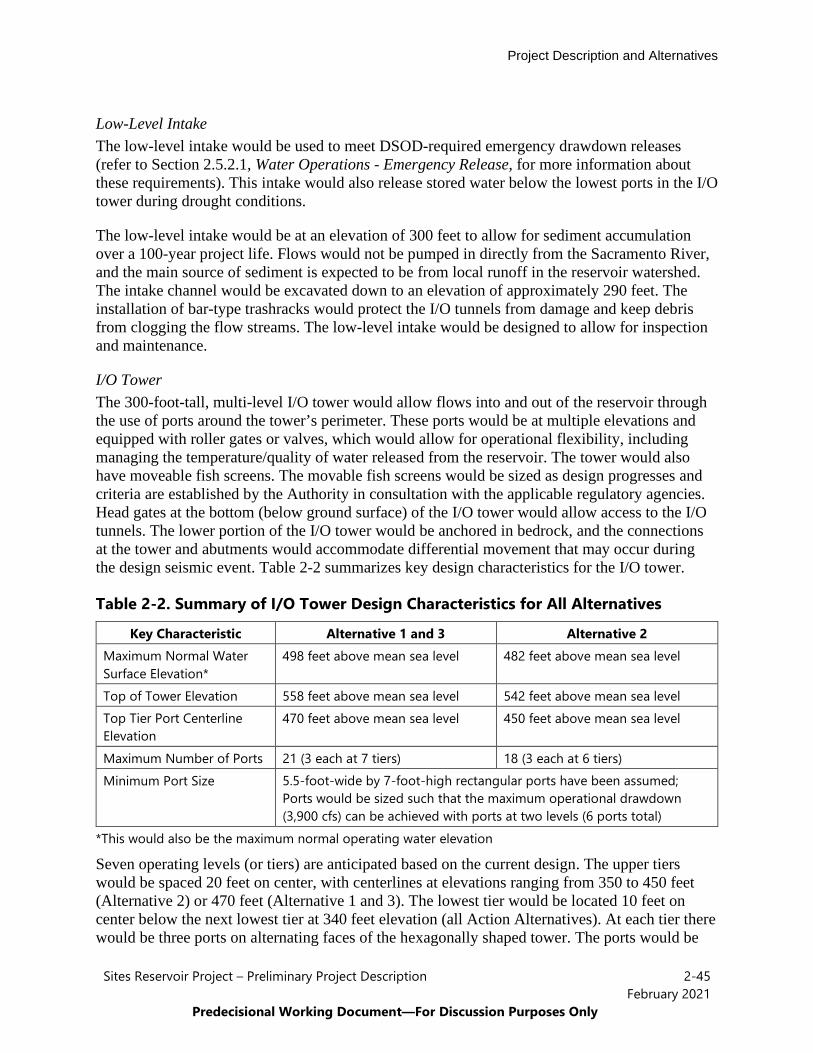
Low-Level Intake The low-level intake would be used to meet DSOD-required emergency drawdown releases (refer to Section 2.5.2.1, Water Operations - Emergency Release, for more information about these requirements). This intake would also release stored water below the lowest ports in the I/O tower during drought conditions.
The low-level intake would be at an elevation of 300 feet to allow for sediment accumulation over a 100-year project life. Flows would not be pumped in directly from the Sacramento River, and the main source of sediment is expected to be from local runoff in the reservoir watershed. The intake channel would be excavated down to an elevation of approximately 290 feet. The installation of bar-type trashracks would protect the I/O tunnels from damage and keep debris from clogging the flow streams. The low-level intake would be designed to allow for inspection and maintenance.
I/O Tower The 300-foot-tall, multi-level I/O tower would allow flows into and out of the reservoir through the use of ports around the tower’s perimeter. These ports would be at multiple elevations and equipped with roller gates or valves, which would allow for operational flexibility, including managing the temperature/quality of water released from the reservoir. The tower would also have moveable fish screens. The movable fish screens would be sized as design progresses and criteria are established by the Authority in consultation with the applicable regulatory agencies. Head gates at the bottom (below ground surface) of the I/O tower would allow access to the I/O tunnels. The lower portion of the I/O tower would be anchored in bedrock, and the connections at the tower and abutments would accommodate differential movement that may occur during the design seismic event. Table 2-2 summarizes key design characteristics for the I/O tower.
Table 2-2. Summary of I/O Tower Design Characteristics for All Alternatives
Key Characteristic Alternative 1 and 3 Alternative 2 Maximum Normal Water Surface Elevation*
498 feet above mean sea level 482 feet above mean sea level
Top of Tower Elevation 558 feet above mean sea level 542 feet above mean sea level Top Tier Port Centerline Elevation
470 feet above mean sea level 450 feet above mean sea level
Maximum Number of Ports 21 (3 each at 7 tiers) 18 (3 each at 6 tiers) Minimum Port Size 5.5-foot-wide by 7-foot-high rectangular ports have been assumed;
Ports would be sized such that the maximum operational drawdown (3,900 cfs) can be achieved with ports at two levels (6 ports total)
*This would also be the maximum normal operating water elevation
Seven operating levels (or tiers) are anticipated based on the current design. The upper tiers would be spaced 20 feet on center, with centerlines at elevations ranging from 350 to 450 feet (Alternative 2) or 470 feet (Alternative 1 and 3). The lowest tier would be located 10 feet on center below the next lowest tier at 340 feet elevation (all Action Alternatives). At each tier there would be three ports on alternating faces of the hexagonally shaped tower. The ports would be
Project Description and Alternatives
Sites Reservoir Project – Preliminary Project Description 2-46February 2021
Predecisional Working Document—For Discussion Purposes Only
constructed at different elevations to allow flexibility to withdraw water based on its quality (e.g., temperature, turbidity) needs. These ports would be controlled by roller gates or valves.
The head gates would be located in the I/O tower base (below ground surface) to allow the isolation of its tunnels for maintenance, inspection, and operational needs. The head gates would be designed to prevent outflow from the I/O tower at the full range of reservoir levels. The gates would be able to open (i.e., raised) and close under all normal reservoir operations and if emergency releases were required. Gates for either I/O tunnel would be closed to prevent outflow for operational purposes (downstream release or equipment preference, maintenance, or dewatering for inspection or equipment change out). Emergency raising and lowering of the gates by emergency power upon loss of electricity would be required.
A bridge would provide access to the I/O tower from the nearby access road. The bridge would be designed to accommodate equipment and materials required for maintenance of the tower. The bridge’s length would depend on the access road design but is expected to be approximately 300 feet.
Two 23-foot-diameter I/O tunnels would extend from the I/O tower through the ridge on the right abutment of Golden Gate Dam. They would daylight on the other side of the ridge and connect to the transition manifold. The tunnels would each be about 3,110 feet long, connect to the multi-level tower at approximately 300 feet elevation, and have a downstream slope of 1%.
Dams and Dikes All Action Alternatives would include Sites Dam and Golden Gate Dam along with a number of saddle dams and saddle dikes. The height of these facilities and the number of saddle dams and dikes varies between the Action Alternatives as summarized in Table 2-3. Sites Dam, Golden Gate Dam and the saddle dams and saddle dikes are discussed in more detail below.

Project Description and Alternatives
Sites Reservoir Project – Preliminary Project Description 2-47February 2021
Predecisional Working Document—For Discussion Purposes Only
Table 2-3. Main Dam, Saddle Dam and Saddle Dike Summary for All Alternatives
Dam/Dike Alternative 1 and 3 Alternative 2 Maximum
Height Above Streambed (feet) Length (feet)
Maximum Height Above
Streambed (feet) Length (feet) Sites Dam 267 781 250 729 Golden Gate Dam 287 2,221 270 2,063 Saddle Dam 1 27 318 -- -- Saddle Dam 2 57 250 -- -- Saddle Dam 3 107 3,422 90 2,677 Saddle Dam 5 77 1,894 60 1,747 Saddle Dam 6 47 362 -- -- Saddle Dam 8A 82 1,300 62 1,140 Saddle Dam 8B 37 475 20 277 Saddle Dike 1 12 122 10 148 Saddle Dike 2 12 198 20 79 Saddle Dike 3 -- -- 30 247
Sites Dam and Diversion Tunnel Sites Dam would be on Stone Corral Creek approximately 0.25 mile east of the community of Sites and 8 miles west of the community of Maxwell. The dam would be designed to safely accommodate potential fault displacement by providing widened filter, drainage, and transition zones. Sites Dam would be an embankment dam consisting of a combination of earth and rockfill embankment zones with a central impervious core, exterior upstream rockfill shell, and downstream earthen shell. The upstream and downstream slopes of the dam embankment would be 2.25:1 (horizontal: vertical; H:V) and 2H:1V, respectively. The upstream and downstream slopes of the dam’s central core would be 0.5H:1V. Figure 2-26 provides a plan view of Sites Dam and Figure 2-27 provides a section view of Sites Dam.
Sites Dam would have a permanent diversion pipeline and tunnel that would be constructed in the left abutment of the dam. The approximately 1,600-foot-long tunnel would contain a 1,900-foot-long pipe with an internal diameter of 12 feet. The pipe would be fitted with one or more valves sized to release flow up to 100 cfs into Stone Corral Creek. The Sites Dam piping system is expected to include a bar trashrack, a slide gate, a separate fish screen and inlet valve to support Stone Corral Creek release flows, a stoplog bulkhead, and a permanent air vent assembly. The fish screen would be designed and sized to meet the requirements for aquatic life protection.

Project Description and Alternatives
Sites Reservoir Project – Preliminary Project Description 2-48February 2021
Predecisional Working Document—For Discussion Purposes Only
Figure 2-26. Sites Dam Plan

Project Description and Alternatives
Sites Reservoir Project – Preliminary Project Description 2-49February 2021
Predecisional Working Document—For Discussion Purposes Only
Figure 2-27. Sites Dam Section
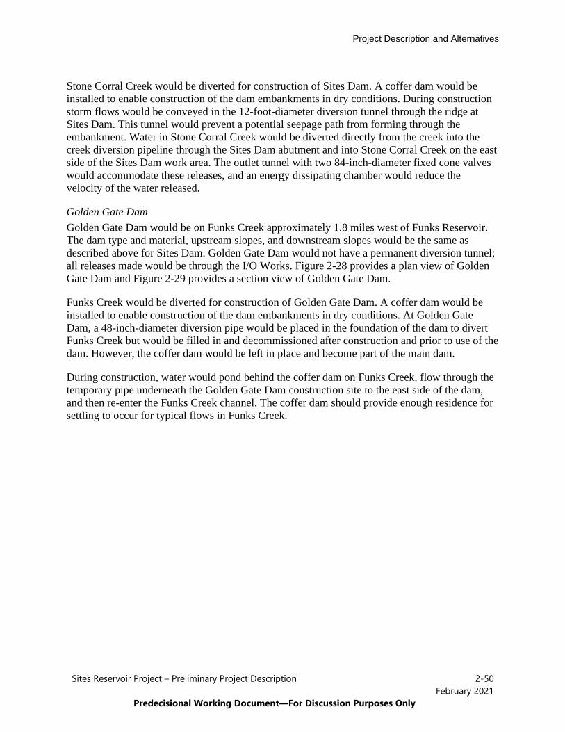
Project Description and Alternatives
Sites Reservoir Project – Preliminary Project Description 2-50February 2021
Predecisional Working Document—For Discussion Purposes Only
Stone Corral Creek would be diverted for construction of Sites Dam. A coffer dam would be installed to enable construction of the dam embankments in dry conditions. During construction storm flows would be conveyed in the 12-foot-diameter diversion tunnel through the ridge at Sites Dam. This tunnel would prevent a potential seepage path from forming through the embankment. Water in Stone Corral Creek would be diverted directly from the creek into the creek diversion pipeline through the Sites Dam abutment and into Stone Corral Creek on the east side of the Sites Dam work area. The outlet tunnel with two 84-inch-diameter fixed cone valves would accommodate these releases, and an energy dissipating chamber would reduce the velocity of the water released.
Golden Gate Dam Golden Gate Dam would be on Funks Creek approximately 1.8 miles west of Funks Reservoir. The dam type and material, upstream slopes, and downstream slopes would be the same as described above for Sites Dam. Golden Gate Dam would not have a permanent diversion tunnel; all releases made would be through the I/O Works. Figure 2-28 provides a plan view of Golden Gate Dam and Figure 2-29 provides a section view of Golden Gate Dam.
Funks Creek would be diverted for construction of Golden Gate Dam. A coffer dam would be installed to enable construction of the dam embankments in dry conditions. At Golden Gate Dam, a 48-inch-diameter diversion pipe would be placed in the foundation of the dam to divert Funks Creek but would be filled in and decommissioned after construction and prior to use of the dam. However, the coffer dam would be left in place and become part of the main dam.
During construction, water would pond behind the coffer dam on Funks Creek, flow through the temporary pipe underneath the Golden Gate Dam construction site to the east side of the dam, and then re-enter the Funks Creek channel. The coffer dam should provide enough residence for settling to occur for typical flows in Funks Creek.
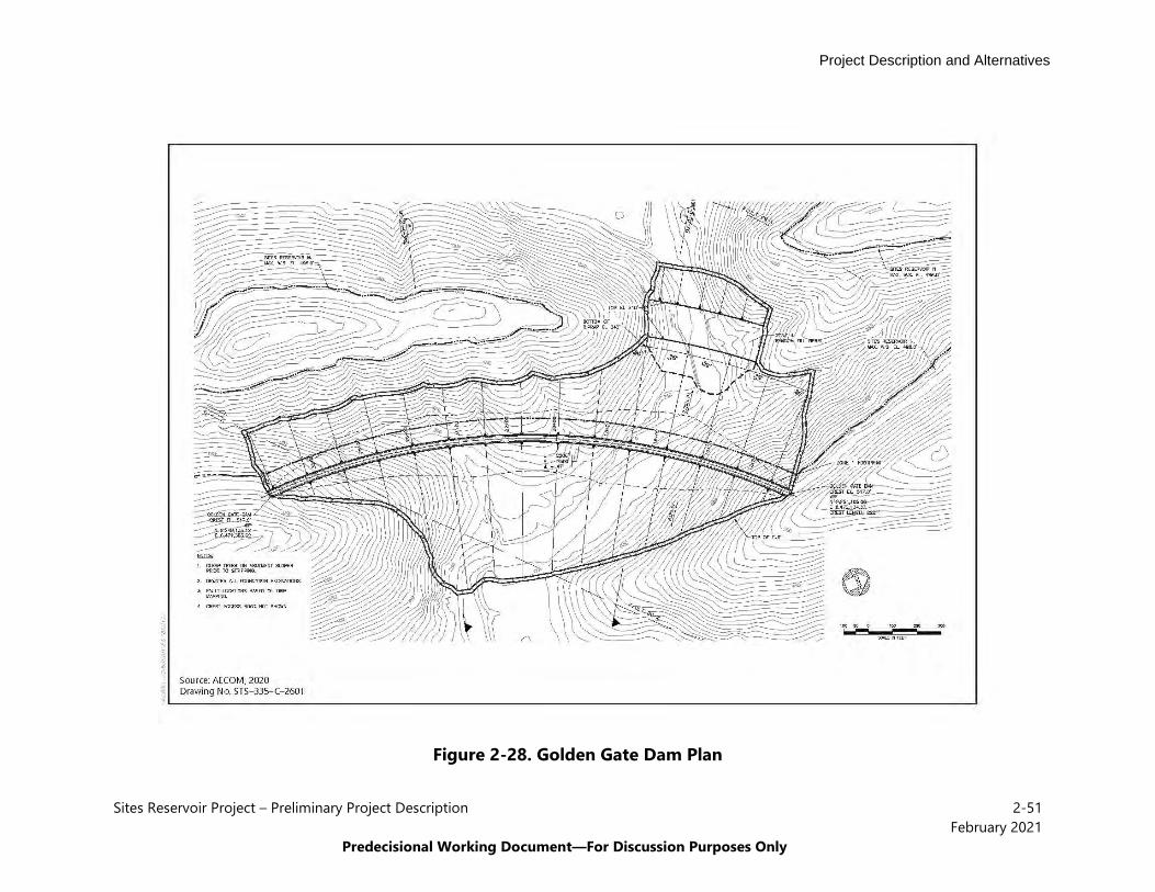
Project Description and Alternatives
Sites Reservoir Project – Preliminary Project Description 2-51February 2021
Predecisional Working Document—For Discussion Purposes Only
Figure 2-28. Golden Gate Dam Plan

Project Description and Alternatives
Sites Reservoir Project – Preliminary Project Description 2-52February 2021
Predecisional Working Document—For Discussion Purposes Only
Figure 2-29. Golden Gate Dam Section
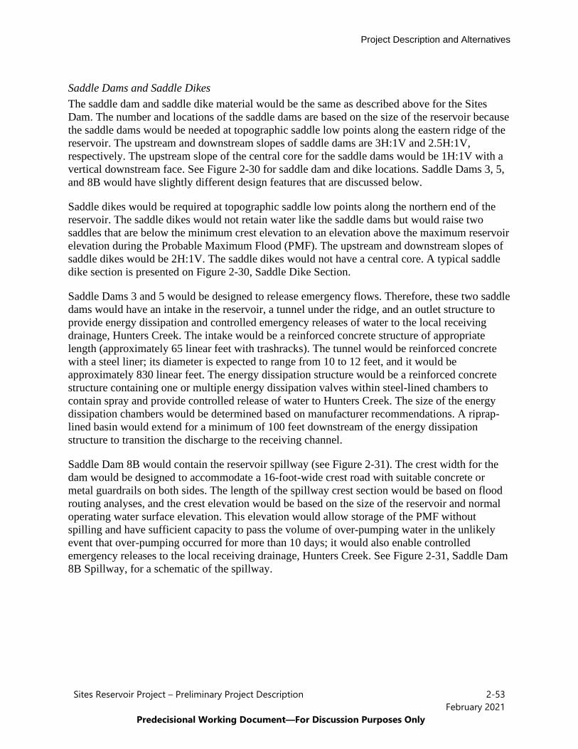
Project Description and Alternatives
Sites Reservoir Project – Preliminary Project Description 2-53February 2021
Predecisional Working Document—For Discussion Purposes Only
Saddle Dams and Saddle Dikes The saddle dam and saddle dike material would be the same as described above for the Sites Dam. The number and locations of the saddle dams are based on the size of the reservoir because the saddle dams would be needed at topographic saddle low points along the eastern ridge of the reservoir. The upstream and downstream slopes of saddle dams are 3H:1V and 2.5H:1V, respectively. The upstream slope of the central core for the saddle dams would be 1H:1V with a vertical downstream face. See Figure 2-30 for saddle dam and dike locations. Saddle Dams 3, 5, and 8B would have slightly different design features that are discussed below.
Saddle dikes would be required at topographic saddle low points along the northern end of the reservoir. The saddle dikes would not retain water like the saddle dams but would raise two saddles that are below the minimum crest elevation to an elevation above the maximum reservoir elevation during the Probable Maximum Flood (PMF). The upstream and downstream slopes of saddle dikes would be 2H:1V. The saddle dikes would not have a central core. A typical saddle dike section is presented on Figure 2-30, Saddle Dike Section.
Saddle Dams 3 and 5 would be designed to release emergency flows. Therefore, these two saddle dams would have an intake in the reservoir, a tunnel under the ridge, and an outlet structure to provide energy dissipation and controlled emergency releases of water to the local receiving drainage, Hunters Creek. The intake would be a reinforced concrete structure of appropriate length (approximately 65 linear feet with trashracks). The tunnel would be reinforced concrete with a steel liner; its diameter is expected to range from 10 to 12 feet, and it would be approximately 830 linear feet. The energy dissipation structure would be a reinforced concrete structure containing one or multiple energy dissipation valves within steel-lined chambers to contain spray and provide controlled release of water to Hunters Creek. The size of the energy dissipation chambers would be determined based on manufacturer recommendations. A riprap-lined basin would extend for a minimum of 100 feet downstream of the energy dissipation structure to transition the discharge to the receiving channel.
Saddle Dam 8B would contain the reservoir spillway (see Figure 2-31). The crest width for the dam would be designed to accommodate a 16-foot-wide crest road with suitable concrete or metal guardrails on both sides. The length of the spillway crest section would be based on flood routing analyses, and the crest elevation would be based on the size of the reservoir and normal operating water surface elevation. This elevation would allow storage of the PMF without spilling and have sufficient capacity to pass the volume of over-pumping water in the unlikely event that over-pumping occurred for more than 10 days; it would also enable controlled emergency releases to the local receiving drainage, Hunters Creek. See Figure 2-31, Saddle Dam 8B Spillway, for a schematic of the spillway.
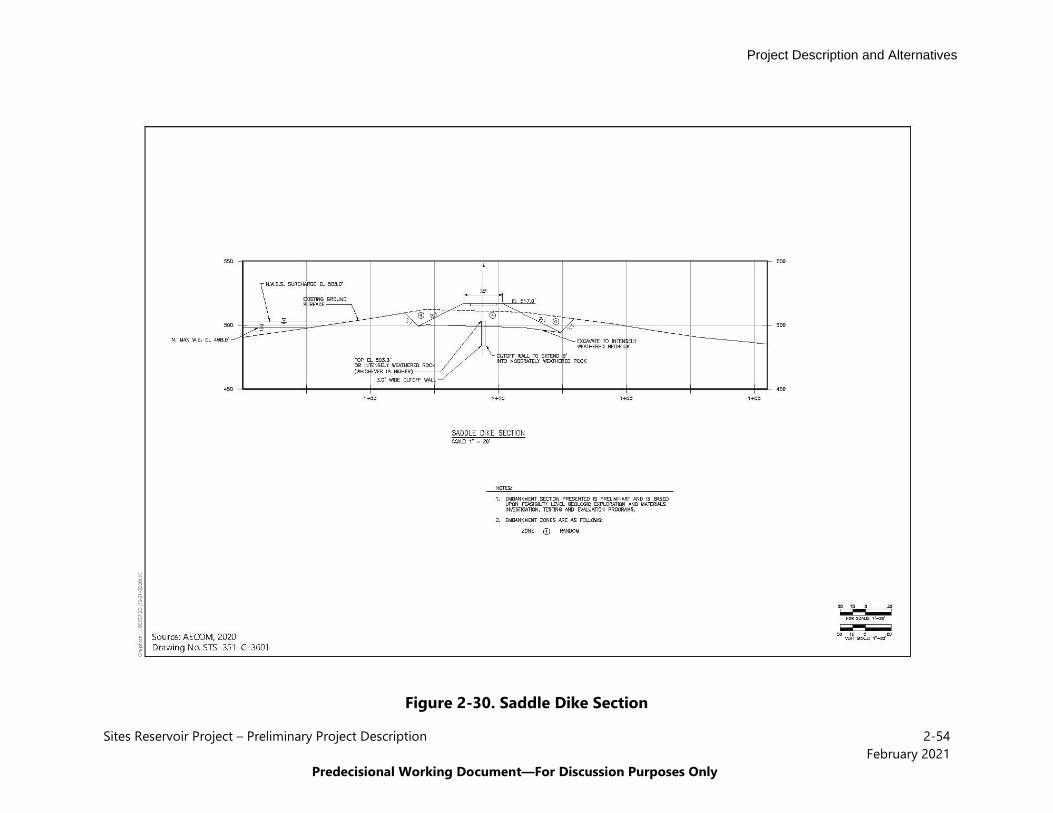
Project Description and Alternatives
Sites Reservoir Project – Preliminary Project Description 2-54February 2021
Predecisional Working Document—For Discussion Purposes Only
Figure 2-30. Saddle Dike Section

Project Description and Alternatives
Sites Reservoir Project – Preliminary Project Description 2-55February 2021
Predecisional Working Document—For Discussion Purposes Only
Figure 2-31. Saddle Dam 8B Spillway
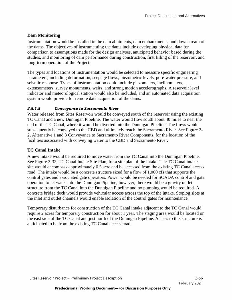
Project Description and Alternatives
Sites Reservoir Project – Preliminary Project Description 2-56February 2021
Predecisional Working Document—For Discussion Purposes Only
Dam Monitoring Instrumentation would be installed in the dam abutments, dam embankments, and downstream of the dams. The objectives of instrumenting the dams include developing physical data for comparison to assumptions made for the design analyses, anticipated behavior based during the studies, and monitoring of dam performance during construction, first filling of the reservoir, and long-term operation of the Project.
The types and locations of instrumentation would be selected to measure specific engineering parameters, including deformation, seepage flows, piezometric levels, pore-water pressure, and seismic response. Types of instrumentation could include piezometers, inclinometers, extensometers, survey monuments, weirs, and strong motion accelerographs. A reservoir level indicator and meteorological station would also be included, and an automated data acquisition system would provide for remote data acquisition of the dams.
2.5.1.5 Conveyance to Sacramento River Water released from Sites Reservoir would be conveyed south of the reservoir using the existing TC Canal and a new Dunnigan Pipeline. The water would flow south about 40 miles to near the end of the TC Canal, where it would be diverted into the Dunnigan Pipeline. The flows would subsequently be conveyed to the CBD and ultimately reach the Sacramento River. See Figure 2-2, Alternative 1 and 3 Conveyance to Sacramento River Components, for the location of the facilities associated with conveying water to the CBD and Sacramento River.
TC Canal Intake A new intake would be required to move water from the TC Canal into the Dunnigan Pipeline. See Figure 2-32, TC Canal Intake Site Plan, for a site plan of the intake. The TC Canal intake site would encompass approximately 0.5 acre and be accessed from the existing TC Canal access road. The intake would be a concrete structure sized for a flow of 1,000 cfs that supports the control gates and associated gate operators. Power would be needed for SCADA control and gate operation to let water into the Dunnigan Pipeline; however, there would be a gravity outlet structure from the TC Canal into the Dunnigan Pipeline and no pumping would be required. A concrete bridge deck would provide vehicular access across the top of the intake. Stoplog slots at the inlet and outlet channels would enable isolation of the control gates for maintenance.
Temporary disturbance for construction of the TC Canal intake adjacent to the TC Canal would require 2 acres for temporary construction for about 1 year. The staging area would be located on the east side of the TC Canal and just north of the Dunnigan Pipeline. Access to this structure is anticipated to be from the existing TC Canal access road.
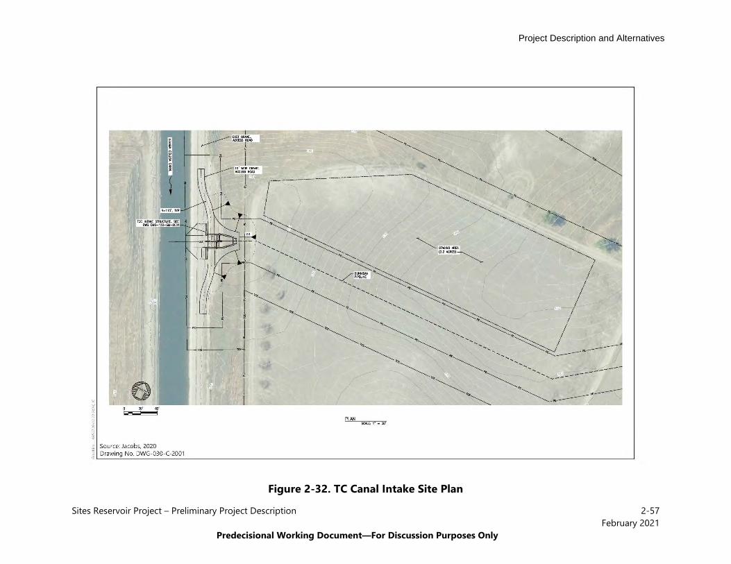
Project Description and Alternatives
Sites Reservoir Project – Preliminary Project Description 2-57February 2021
Predecisional Working Document—For Discussion Purposes Only
Figure 2-32. TC Canal Intake Site Plan

Project Description and Alternatives
Sites Reservoir Project – Preliminary Project Description 2-58February 2021
Predecisional Working Document—For Discussion Purposes Only
Dunnigan Pipeline The Dunnigan Pipeline would convey water released from the TC Canal to the CBD. See Figure 2-33, Dunnigan CBD Discharge Site Plan, for the location of this facility. The Dunnigan pipelinewould be about 4 miles long, have a minimum depth of 6 feet below ground surface, and have aninside diameter of approximately 9 feet (Alternative 1 and 3) to 10.5 feet (Alternative 2). TheDunnigan Pipeline would extend through existing agricultural lands, as well as crossingInterstate 5 (I-5), Road 99W, the railroad, and a commercial auction yard between I-5 and Road99W. The tunneled crossings at I-5, Road 99W and the railroad would be 300 feet long and 250feet long, respectively, and would require 12-5-foot-diameter casings.
A CBD outlet with an energy dissipation facility would be required at the downstream end of the pipeline prior to discharging the water into the CBD. Two 60-inch-diameter, fixed-cone valves would be placed at the discharge stilling basin to dissipate energy and adjust the flow. Hoods on the fixed-cones valves would control spray. The conveyance through the Dunnigan Pipeline to the CBD would use gravity (i.e., no pump station) and have a flow up to 1,000 cfs.
Construction of the Dunnigan Pipeline from the TC Canal to the CBD would require dewatering, trenching, and pile driving or a vibration hammer. Dewatering would be necessary for a segment of the pipeline to reduce groundwater levels to 20 or 30 feet below ground surface along its length. Trenching and pipeline installation would be completed after dewatering. Pile driving or a vibration hammer would be used to install piles for construction of the CBD outlet. Construction would include open cut of approximately 100 feet to cross Bird Creek in the dry season.
2.5.1.6 Recreation Areas The Project proposes the development of two primary recreation areas and a day-use boat ramp. The recreation areas would also require a network of new roads and upgrades to existing roads for maintenance and local access (see Section 2.5.1.7, New and Existing Roadways a). Figure 2-34, Recreation Areas, shows a conceptual site map of each recreation area and the recreationareas are described below.
• Peninsula Hills Recreation Area – The Peninsula Hills Recreation Area would belocated on the northwest shore of the Sites Reservoir, to the north of the existing SitesLodoga Road and across the reservoir from the Stone Corral Creek Recreation Area.Access would be provided by the existing Sites Lodoga Road west of the reservoir. Thisrecreation area would encompass up to 373 acres and would include a kiosk, access toelectricity and potable water, 10 picnic sites (with parking at each site), and hiking trails.There would also be 19 vault toilets, 200 campsites (car and recreational vehicle), andone group camp area.

Project Description and Alternatives
Sites Reservoir Project – Preliminary Project Description 2-59February 2021
Predecisional Working Document—For Discussion Purposes Only
Figure 2-33. Dunnigan CBD Discharge Site Plan

Project Description and Alternatives
Sites Reservoir Project – Preliminary Project Description 2-60February 2021
Predecisional Working Document—For Discussion Purposes Only
Figure 2-34. Recreation Areas
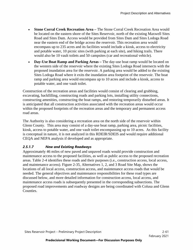
Project Description and Alternatives
Sites Reservoir Project – Preliminary Project Description 2-61February 2021
Predecisional Working Document—For Discussion Purposes Only
• Stone Corral Creek Recreation Area – The Stone Corral Creek Recreation Area wouldbe located on the eastern shore of the Sites Reservoir, north of the existing Maxwell SitesRoad and Sites Dam. Access would be provided from Sites Dam and Sites Lodoga Roadnear the eastern end of the bridge across the reservoir. This recreation area wouldencompass up to 235 acres and its facilities would include a kiosk, access to electricityand potable water, 10 picnic sites (with parking at each site), and hiking trails. Therewould also be 10 vault toilets and 50 campsites (car and recreational vehicle).
• Day-Use Boat Ramp and Parking Areas – The day-use boat ramp would be located onthe western side of the reservoir where the existing Sites Lodoga Road intersects with theproposed inundation area for the reservoir. A parking area would be added to the existingSites Lodoga Road where it exits the inundation area footprint of the reservoir. The boatramp and parking area would encompass up to 10 acres and include a kiosk, access topotable water, and one vault toilet.
Construction of the recreation areas and facilities would consist of clearing and grubbing, excavating, backfilling, constructing roads and parking lots, installing utility connections, constructing amenities, constructing the boat ramps, and restoring temporarily disturbed areas. It is anticipated that all construction activities associated with the recreation areas would occur within the proposed footprints of the recreation areas and the temporary and permanent access road areas.
The Authority is also considering a recreation area on the north side of the reservoir within Glenn County. This area may consist of a day-use boat ramp, parking area, picnic facilities, kiosk, access to potable water, and one vault toilet encompassing up to 10 acres. As this facility is conceptual in nature, it is not analyzed in this RDEIR/SDEIS and would require additional CEQA and NEPA analysis if developed and as appropriate.
2.5.1.7 New and Existing Roadways Approximately 46 miles of new paved and unpaved roads would provide construction and maintenance access to the proposed facilities, as well as public access to the proposed recreation areas. Table 2-4 identifies these roads and their purposes (i.e., construction access, local access, and maintenance access). Figure 2-35, Alternatives 1, 2, and 3 Road Site Map, shows the locations of all local access, construction access, and maintenance access roads that would be needed. The general objectives and maintenance responsibilities for these road types are discussed below, and more detailed information for construction access, local access, and maintenance access roads is subsequently presented in the corresponding subsections. The proposed road improvements and roadway designs are being coordinated with Colusa and Glenn Counties.
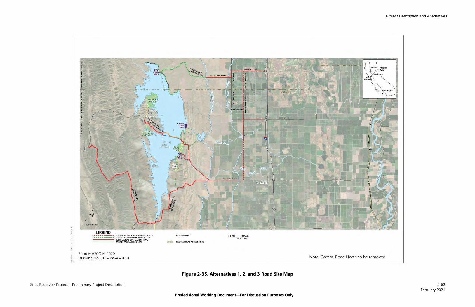
Project Description and Alternatives
Sites Reservoir Project – Preliminary Project Description 2-62February 2021
Predecisional Working Document—For Discussion Purposes Only
Figure 2-35. Alternatives 1, 2, and 3 Road Site Map
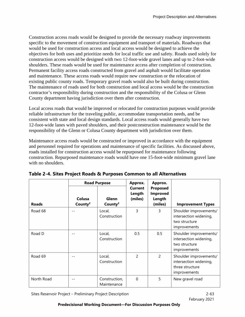
Project Description and Alternatives
Sites Reservoir Project – Preliminary Project Description 2-63February 2021
Predecisional Working Document—For Discussion Purposes Only
Construction access roads would be designed to provide the necessary roadway improvements specific to the movement of construction equipment and transport of materials. Roadways that would be used for construction access and local access would be designed to achieve the objectives for both uses and prioritize needs for local traffic use and safety. Roads used solely for construction access would be designed with two 12-foot-wide gravel lanes and up to 2-foot-wide shoulders. These roads would be used for maintenance access after completion of construction. Permanent facility access roads constructed from gravel and asphalt would facilitate operation and maintenance. These access roads would require new construction or the relocation of existing public county roads. Temporary gravel roads would also be built during construction. The maintenance of roads used for both construction and local access would be the construction contractor’s responsibility during construction and the responsibility of the Colusa or Glenn County department having jurisdiction over them after construction.
Local access roads that would be improved or relocated for construction purposes would provide reliable infrastructure for the traveling public, accommodate transportation needs, and be consistent with state and local design standards. Local access roads would generally have two 12-foot-wide lanes with paved shoulders, and their postconstruction maintenance would be theresponsibility of the Glenn or Colusa County department with jurisdiction over them.
Maintenance access roads would be constructed or improved in accordance with the equipment and personnel required for operations and maintenance of specific facilities. As discussed above, roads installed for construction access would be repurposed for maintenance following construction. Repurposed maintenance roads would have one 15-foot-wide minimum gravel lane with no shoulders.
Table 2-4. Sites Project Roads & Purposes Common to all Alternatives
Road Purpose Approx. Current Length (miles)
Approx. Proposed Improved
Length (miles) Roads
Colusa County2
Glenn County2 Improvement Types
Road 68 -- Local, Construction
3 3 Shoulder improvements/ intersection widening, two structure improvements
Road D -- Local, Construction
0.5 0.5 Shoulder improvements/ intersection widening, two structure improvements
Road 69 -- Local, Construction
2 2 Shoulder improvements/ intersection widening, three structure improvements
North Road -- Construction, Maintenance
0 5 New gravel road

Project Description and Alternatives
Sites Reservoir Project – Preliminary Project Description 2-64February 2021
Predecisional Working Document—For Discussion Purposes Only
Road Purpose Approx. Current Length (miles)
Approx. Proposed Improved
Length (miles) Roads
Colusa County2
Glenn County2 Improvement Types
Delevan Road Local, Construction
2 2 Shoulder improvements/ widening
McDermott Road Local, Construction
Local, Construction
8 4 Shoulder improvements/ widening/paving, five structure improvements
Saddle Dam Road – North (5–9) (provide access to northern portions of Sites Reservoir and the saddle dams)
-- Construction, Maintenance
1 2 New gravel road
Saddle Dam Road – South (1–5)
Maintenance Maintenance 0 3 New road
Huffmaster Road realigned
Local -- 12 7 Gravel road for residents
Sites Lodoga Temporary Detour Road (Shoo-Fly)
Local, Construction
-- 1 1 New, temporary gravel road
Day-Use Boat Ramp (westside)
Local -- 0 0.3 New paved road
Peninsula Hills Recreation Area (provide access from Sites Lodoga Road to the proposed Peninsula Hills Recreation Area)
Local -- 0 4 New gravel road
Potential Access Road A (O&M/PGP/GG Dam)
Maintenance -- 0 1 New road
Potential Access Road B (O&M/PGP/GG Dam)
Maintenance -- 0 0.4 New road
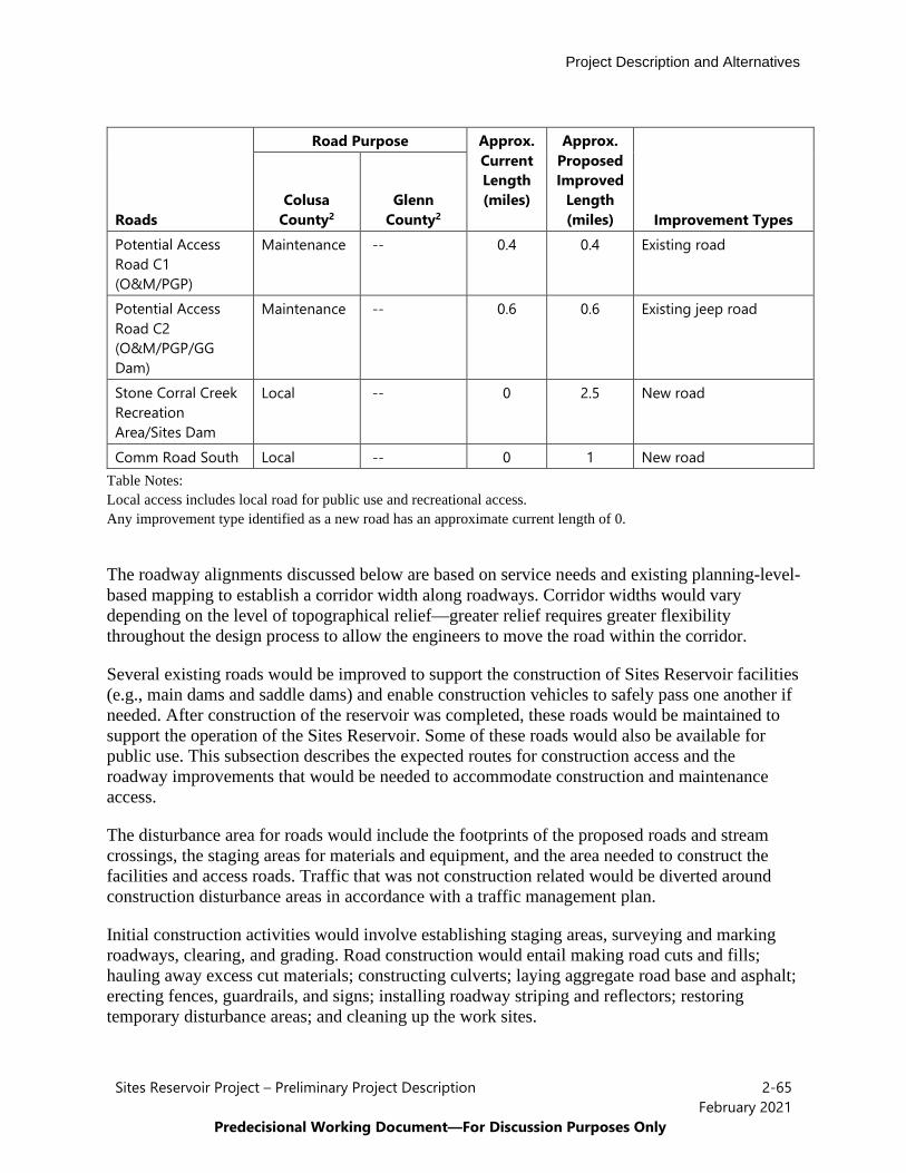
Project Description and Alternatives
Sites Reservoir Project – Preliminary Project Description 2-65February 2021
Predecisional Working Document—For Discussion Purposes Only
Road Purpose Approx. Current Length (miles)
Approx. Proposed Improved
Length (miles) Roads
Colusa County2
Glenn County2 Improvement Types
Potential Access Road C1 (O&M/PGP)
Maintenance -- 0.4 0.4 Existing road
Potential Access Road C2 (O&M/PGP/GG Dam)
Maintenance -- 0.6 0.6 Existing jeep road
Stone Corral Creek Recreation Area/Sites Dam
Local -- 0 2.5 New road
Comm Road South Local -- 0 1 New road Table Notes: Local access includes local road for public use and recreational access. Any improvement type identified as a new road has an approximate current length of 0.
The roadway alignments discussed below are based on service needs and existing planning-level-based mapping to establish a corridor width along roadways. Corridor widths would vary depending on the level of topographical relief—greater relief requires greater flexibility throughout the design process to allow the engineers to move the road within the corridor.
Several existing roads would be improved to support the construction of Sites Reservoir facilities (e.g., main dams and saddle dams) and enable construction vehicles to safely pass one another if needed. After construction of the reservoir was completed, these roads would be maintained to support the operation of the Sites Reservoir. Some of these roads would also be available for public use. This subsection describes the expected routes for construction access and the roadway improvements that would be needed to accommodate construction and maintenance access.
The disturbance area for roads would include the footprints of the proposed roads and stream crossings, the staging areas for materials and equipment, and the area needed to construct the facilities and access roads. Traffic that was not construction related would be diverted around construction disturbance areas in accordance with a traffic management plan.
Initial construction activities would involve establishing staging areas, surveying and marking roadways, clearing, and grading. Road construction would entail making road cuts and fills; hauling away excess cut materials; constructing culverts; laying aggregate road base and asphalt; erecting fences, guardrails, and signs; installing roadway striping and reflectors; restoring temporary disturbance areas; and cleaning up the work sites.
Project Description and Alternatives
Sites Reservoir Project – Preliminary Project Description 2-66February 2021
Predecisional Working Document—For Discussion Purposes Only
Construction Access Construction access for the reservoir and supporting facilities would occur on public roads from I-5 to the reservoir site on the north and at Sites Lodoga Road on the east. These roads currentlycross small creeks and irrigation canals, and the crossings are generally reinforced throughconcrete box culverts. There are three primary construction access routes for consideration thatwould most likely be defined for use by the construction contractor.
The first construction access route would be on 5.5 miles of existing approximately 24 feet wide paved road from I-5 west along Road 68, south on Road D, and west on Road 69 to just west of the TC Canal. From here the road reverts to a single lane (± 12 feet wide) gravel road (North Road), which would be temporary and continue for approximately 5 miles along existing ranch roads and trails to the north end of the reservoir at the saddle dams. From this location, the contractor would establish their own onsite access roads within the limits of the reservoir.
The second construction access route would be on 7.2 miles of existing paved road from I-5 west along Delevan Road, north along McDermott Road, and west on Road 69 to just west of the TC Canal as noted above. Approximately 1.5 miles of McDermott Road between Dirks Road and West Glenn Road consist of gravel; therefore, it is assumed paving would be needed to accommodate the volume of heavy construction traffic.
The third construction access route would be on 12 miles of existing paved road from I-5 along Delevan Road, south along McDermott Road to Maxwell Sites Road, and then west to the existing gravel access road to Funks Reservoir. The first mile of this gravel road would be the initial segment of the Sites Lodoga Road realignment. This gravel road would also provide access to the Funks PGP and Golden Gate Dam. Maxwell Sites Road would provide access to Sites Dam. Construction equipment/materials would not be permitted to pass through the community of Maxwell on the Maxwell Sites Road, thus the construction access roads would circumvent Maxwell.
The existing roads are nonstandard in geometry and have inadequate roadbed structural section to accommodate the large, heavy vehicles that would be used to transport construction equipment and materials. These roads consist of Road 68, Road D, Road 69, Delevan Road, and McDermott Road. They are narrow and typically include two paved 11-foot- or 12-foot-wide lanes and 1- to 3-foot-wide earthen shoulders. The pavement conditions of Road 68, Road D, and Road 69pavement conditions are “at risk”, “poor”, and “very poor”, respectively, upon visual inspectionby project engineers. A segment of McDermott Road in Colusa County is gravel. Road 69transitions to a single-lane, gravel road west of the TC Canal. The following improvementswould need to be implemented on these roadways:
• Roadbed and intersection widening to allow for safe mobility of construction traffic thatwould be comingled with local vehicular and agricultural equipment traffic.
• Roadbed reconstruction to enable use by large, heavy vehicles transporting constructionequipment and materials
• Horizonal and vertical curve corrections• Drainage feature improvements to allow for proper drainage

Project Description and Alternatives
Sites Reservoir Project – Preliminary Project Description 2-67February 2021
Predecisional Working Document—For Discussion Purposes Only
Reconstruction of the roads above would include the addition of new 2-foot-wide paved shoulders to each lane, as well as potential modifications to existing creek and irrigation canal crossings (as described below). The new shoulders would be within the public right-of-way, as would any temporary work areas needed to reconstruct the roads. All existing roadway improvements would be designed to avoid or minimize impacts on existing utility infrastructure and public right-of-way. Once the roads are constructed, all county roads would be maintained by Glenn or Colusa County, while specific access and maintenance roads (e.g., North Road, South Comm Road) would be maintained by the Authority.
The following roads involve the noted number of structures that would need to be crossed. It is assumed that these structures would need to be widened, strengthened, or replaced, depending on their structural condition and load rating capacity.
• Road 68 – two structures• Road D – two structures• Road 69 – three structures (two on paved roads crossing the TC Canal and GCID Main
Canal, and one on a gravel road)• McDermott Road – five structures
Local Access In addition to the local roads described above that would be improved for construction purposes and then remain local access roads, a number of other public local roads would be relocated or developed to accommodate reservoir facilities. These roads include Sites Lodoga Road, Huffmaster Road, Comm Road South, and recreation area roads. There would also be one temporary detour during construction, the Sites Lodoga Temporary Detour Road. Permanent changes to Sites Lodoga Road and Huffmaster Road are discussed in Section 2.6, Alternative 1 Specific Elements and Section 2.7, Alternative 2 Specific Elements below.
• Comm Road South – Access to existing communication facilities would consist of agravel road that would start near the northern end of Huffmaster Road and proceed northto the communications tower.
• Recreation Area Roads – New recreation area roads would provide access from SitesLodoga Road to the Peninsula Hills Recreation Area, day-use boat ramp, and StoneCorral Creek Recreation Area. The access road to Peninsula Hills Recreation Area on thewest side of Sites Reservoir would be paved. The access road to the day-use boat ramp,which would also be on the west side of the reservoir, would be paved. The access roadto the Stone Corral Creek Recreation Area on the east side of the reservoir would bepaved and gravel.
• Sites Lodoga Temporary Detour Road – A temporary detour road would beconstructed to expedite construction and maintain traffic movement through the reservoirsite during the construction of Sites Dam and the bridge across the reservoir (includingfill prisms). This road would convey local traffic for a period of approximately 1 year andwould be aligned around the Sites Dam site partially on the Sites Lodoga realignment

Project Description and Alternatives
Sites Reservoir Project – Preliminary Project Description 2-68February 2021
Predecisional Working Document—For Discussion Purposes Only
from Maxwell Sites Road to near the easterly bridge at the top of the ridge. The temporary detour road would then split off to the south and traverse hilly terrain before Comm Road South rejoining Sites Lodoga Road near its intersection with Peterson Road.
Maintenance Access New and existing maintenance access roads would provide access to the main dams, saddle dams and dikes, I/O Works, and Funks PGP. Except for the existing road to Funks Reservoir, the maintenance access roads would be single-lane, 15-foot-wide gravel roads with no shoulder. Comm Road South would be a local access and maintenance access road.
North Road would begin at the end of the unpaved Road 69, continue 5 miles to the reservoir’s edge, and connect with several new maintenance access roads that would provide access to the saddle dams and dikes. Access Road A1 would be a new gravel road along the crest of the Golden Gate Dam with minor cuts/fills. Access Roads B1 and B2 would be new gravel roads connecting to the I/O Works and Golden Gate Dam with minor cuts/fills. Access Road C1 is expected to be a two-lane, 30-foot-wide, paved road to access Funks Reservoir and the existing road to the reservoir would be maintained. Access Road C2 would be improved from an existing jeep trail at the east base of the Golden Gate Dam to a gravel road that would extend off Access Road C1.
2.5.1.8 Project Buffer The Authority would acquire and maintain a project buffer encompassing the lands beyond the facility footprints. The buffer width would be 100 feet around the Sites Reservoir and related facilities, all buildings, most aboveground components, and recreation areas. The buffer may be less than 100 feet wide if a facility is near a property boundary and the proposed uses do not conflict with the adjacent land uses. Buffers are not anticipated for underground or buried facilities (i.e., Dunnigan Pipeline), transmission lines, or roads (both public and Project maintenance access roads).
Although buffer areas would generally remain undeveloped, the Authority would install limited features and perform periodic maintenance primarily related to reducing fire hazards. These actions would include erecting and maintaining fencing, grading fire breaks/trails, maintaining vegetation (e.g., grazing, tilling, or disking), and performing limited prescribed/controlled burns. The Authority may manage buffer areas as wildlife habitat where appropriate.
2.5.2 Operations and Maintenance Common to All Action Alternatives This section describes the operations and maintenance activities common to all of the Action Alternatives.
2.5.2.1 Water Operations The Project would provide water supply and water supply related environmental benefits to the Sites Storage Partners. Water would be diverted into Sites Reservoir from the Sacramento River at the existing RBPP into the TC Canal and at the existing GCID Hamilton City Pump Station into the GCID Main Canal. Both of these facilities have existing fish screens. Once in the TC Canal, water would be conveyed to the existing Funks Reservoir and pumped into the new Sites Reservoir via the Funks PGP and associated facilities. Once in the GCID Main Canal, water

Project Description and Alternatives
Sites Reservoir Project – Preliminary Project Description 2-69February 2021
Predecisional Working Document—For Discussion Purposes Only
would be conveyed to the new TRR and pumped into the new Sites Reservoir via the TRR PGP and associated facilities. Water could be diverted to storage in Sites Reservoir when the diversion criteria are met and when the Delta is in excess conditions. Diversions to storage could occur anytime between September 1 to June 15, the timeframe that the Sacramento River is not fully appropriated. Water would be held in storage in Sites Reservoir until requested for release by a Sites Storage Partner. Water releases would generally be made from May to November, but could occur at any time of the year depending on the Storage Partner’s need and conveyance capacity to convey water to its intended point of delivery. Water would be released from Sites Reservoir via the I/O Works back through the TRR PGP and into the TRR or back through Funks PGP back into Funks Reservoir. Water released could be used along the GCID Main Canal, along the TC Canal, or conveyed to the new Dunnigan Pipeline and discharged to the Colusa Basin Drain and conveyed via the Sacramento River or the Yolo Bypass to a variety of locations in Delta and south-of-Delta2. Exchanges of water may also occur with the CVP and SWP. Water would also be diverted and impounded from Funks and Stone Corral Creeks and releases from Golden Gate Dam and Sites Dam, respectively, would occur into Funks and Stone Corral Creeks. Water operations are described in more detail below.
The Authority intends to apply for and obtain a water right permit from the State Water Resources Control Board (SWRCB) for the operations of Sites Reservoir. Actual operations would be subject to the terms and conditions of this water right along with all applicable laws, regulations, biological opinions and incidental take permits, and court orders in place at the time. Operations under all Action Alternatives would also require coordination with Reclamation and DWR as described below. The Authority is working with Reclamation and DWR to develop mutually agreeable operating agreements that would describe the approach for coordinating operations with Sites and the CVP and SWP operations, respectively.
Diversion to Sites Reservoir Sites Reservoir would be filled through the diversion of Sacramento River water that generally originates from unregulated tributaries to the Sacramento River downstream from Keswick Dam. Only a small amount of the diversions to Sites Reservoir would come from flood releases from Shasta Lake. Diversions to Sites Reservoir would be made from the Sacramento River at the existing RBPP (River Mile 243) near Red Bluff into the TC Canal and at the existing GCID Hamilton City Pump Station (River Mile 205) near Hamilton City into the GCID Main Canal. Water could be diverted to storage in Sites Reservoir from September 1 to June 15. Diversions would only occur when all of the following conditions are met:
• Flows in the Sacramento River exceed the minimum diversion criteria (described below);• The Delta is in “excess” conditions as determined by Reclamation and DWR;
2 The term south-of-Delta or phrase south of the Delta is used to refer to areas that can receive water from the south Delta pumping facilities, including the SWP Banks Pumping Plant, Reclamation’s Jones and Rock Slough pumping plants, and Contra Costa Water District’s pumping plants. This includes areas south and west of the Delta, such as Contra Costa, Alameda, and Santa Clara counties.

Project Description and Alternatives
Sites Reservoir Project – Preliminary Project Description 2-70February 2021
Predecisional Working Document—For Discussion Purposes Only
• Senior downstream water rights, existing CVP and SWP and other water rights diversionsincluding CVP 215 water and Article 3F water and SWP Article 21 (interruptible supply),and other more senior flow priorities (such as diversions associated with FreeportRegional Water Project and existing Los Vaqueros Reservoir) have been satisfied;
• Flows are available for diversion above flows needed to meet all applicable laws,regulations, biological opinions and incidental take permits, and court orders in place atthe time that diversion occurs. This would include, but is not limited to any flowrequirements in Water Right Decision 1641 (SWRCB, 2000), the 2019 ROC on LTOBiological Opinions (USFWS 2019 and NMFS 2019) and the SWP ITP (CDFW 2020);and
• There is available capacity at the RBPP and in the TC Canal and GCID facilities to divertand convey water to Sites Reservoir, above the capacity needed for deliveries to existingTC Canal users and within the GCID service area.
The RBPP would serve as the primary diversion location and would divert water from the Sacramento River to Funks Reservoir through the TC Canal and into the Sites Reservoir through the Funks PGP and the I/O Works. Up to 2,100 cfs, plus losses, would be diverted at the RBPP for the Project. The RBPP has an existing fish screen that meets NMFS and CDFW fish screen criteria through which all flows diverted for the Project would be screened. The Hamilton City Pump Station would serve as the secondary diversion location and would divert water from the Sacramento River to the new TRR through the GCID Main Canal and into the Sites Reservoir through the TRR PGP and the I/O Works. Up to 1,800 cfs, plus losses, would be diverted at the Hamilton City Pump Station for the Project. The Hamilton City Pump Station has an existing fish screen that meets NMFS and CDFW fish screen criteria through which all flows diverted for the Project would be screened. Although the RBPP will be the primary diversion point, both facilities would be operated simultaneously when river conditions, facilities, and capacity are available for a maximum combined diversion rate of 3,900 cfs, plus losses.
Estimated total annual diversion of Sacramento River water from both diversion facilities to Sites Reservoir could be up to the full reservoir amount. Based on model simulations, the estimated annual diversions would usually range from 60 thousand acre-feet (TAF) per year to 390 TAF per year, depending on hydrologic conditions, availability of Sacramento River water, and diversion and conveyance facility capacities.
Diversion Criteria The Project would be operated to meet the diversion criteria summarized in Table 2-5 and described in more detail below. All diversion criteria must be met for the Project to divert.
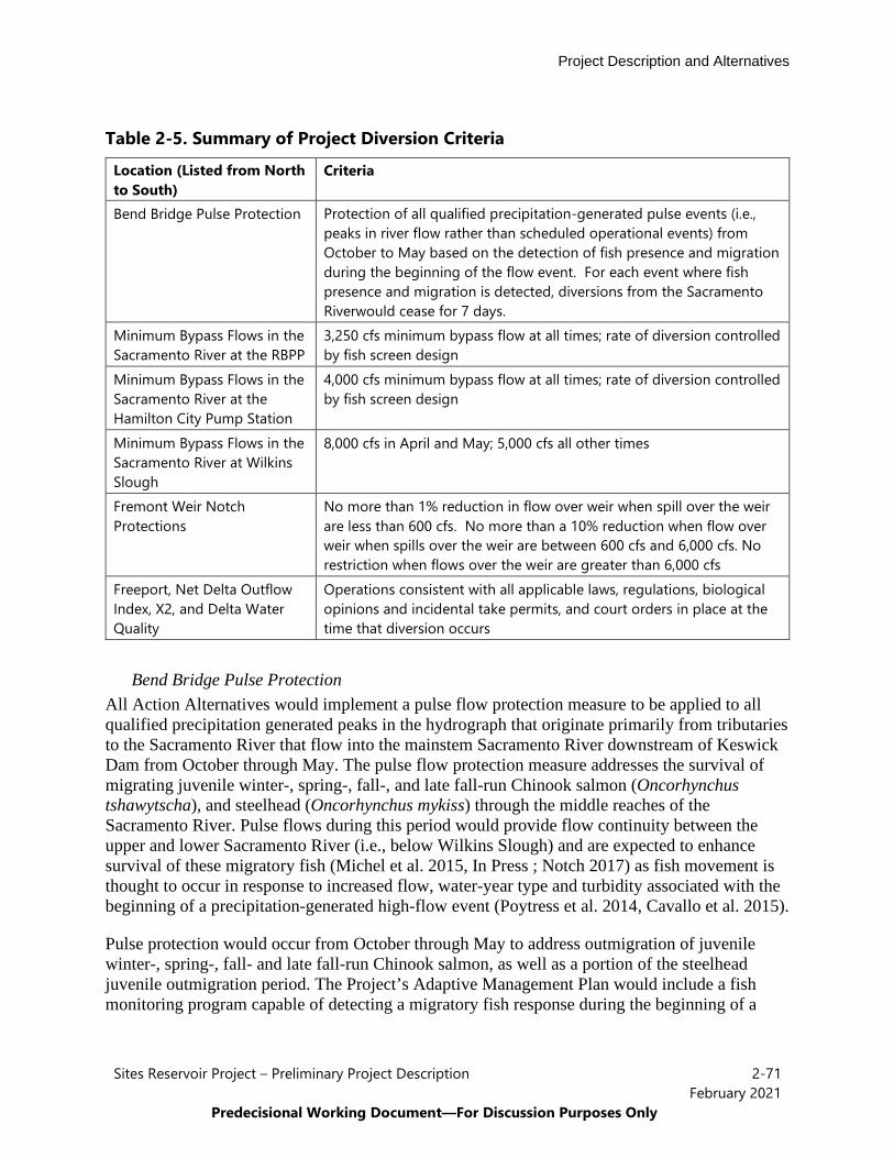
Project Description and Alternatives
Sites Reservoir Project – Preliminary Project Description 2-71February 2021
Predecisional Working Document—For Discussion Purposes Only
Table 2-5. Summary of Project Diversion Criteria
Location (Listed from North to South)
Criteria
Bend Bridge Pulse Protection Protection of all qualified precipitation-generated pulse events (i.e., peaks in river flow rather than scheduled operational events) from October to May based on the detection of fish presence and migration during the beginning of the flow event. For each event where fish presence and migration is detected, diversions from the Sacramento Riverwould cease for 7 days.
Minimum Bypass Flows in the Sacramento River at the RBPP
3,250 cfs minimum bypass flow at all times; rate of diversion controlled by fish screen design
Minimum Bypass Flows in the Sacramento River at the Hamilton City Pump Station
4,000 cfs minimum bypass flow at all times; rate of diversion controlled by fish screen design
Minimum Bypass Flows in the Sacramento River at Wilkins Slough
8,000 cfs in April and May; 5,000 cfs all other times
Fremont Weir Notch Protections
No more than 1% reduction in flow over weir when spill over the weir are less than 600 cfs. No more than a 10% reduction when flow over weir when spills over the weir are between 600 cfs and 6,000 cfs. No restriction when flows over the weir are greater than 6,000 cfs
Freeport, Net Delta Outflow Index, X2, and Delta Water Quality
Operations consistent with all applicable laws, regulations, biological opinions and incidental take permits, and court orders in place at the time that diversion occurs
Bend Bridge Pulse Protection All Action Alternatives would implement a pulse flow protection measure to be applied to all qualified precipitation generated peaks in the hydrograph that originate primarily from tributaries to the Sacramento River that flow into the mainstem Sacramento River downstream of Keswick Dam from October through May. The pulse flow protection measure addresses the survival of migrating juvenile winter-, spring-, fall-, and late fall-run Chinook salmon (Oncorhynchus tshawytscha), and steelhead (Oncorhynchus mykiss) through the middle reaches of the Sacramento River. Pulse flows during this period would provide flow continuity between the upper and lower Sacramento River (i.e., below Wilkins Slough) and are expected to enhance survival of these migratory fish (Michel et al. 2015, In Press ; Notch 2017) as fish movement is thought to occur in response to increased flow, water-year type and turbidity associated with the beginning of a precipitation-generated high-flow event (Poytress et al. 2014, Cavallo et al. 2015).
Pulse protection would occur from October through May to address outmigration of juvenile winter-, spring-, fall- and late fall-run Chinook salmon, as well as a portion of the steelhead juvenile outmigration period. The Project’s Adaptive Management Plan would include a fish monitoring program capable of detecting a migratory fish response during the beginning of a
Project Description and Alternatives
Sites Reservoir Project – Preliminary Project Description 2-72February 2021
Predecisional Working Document—For Discussion Purposes Only
precipitation-generated high flow event and continuing research would be utilized to operate to, and further refine the pulse flow protection strategy.
The Adaptive Management Plan and fish monitoring program would be developed in cooperation with Reclamation and the fishery resource agencies, including CDFW, NMFS, and USFWS and would be integrated with existing fish monitoring programs to the extent possible. For example, the USFWS monitoring program at RBDD, conducted for purposes of estimating fish production indices in the spawning reach above RBDD, is particularly relevant. This program could be supplemented with additional monitoring sites downstream, as necessary. The Authority would coordinate with the fishery resource agencies to define an appropriate capture rate or other metric to define the onset of a fish pulse stimulated by increasing flows and turbidity from storm events. The following criteria define a qualified pulse event:
• Outmigration of anadromous fish is detected based on the Adaptive Management Planand fish monitoring program.
• If the 3-day trailing average of Sacramento River flow at Bend Bridge exceeds 8,000 cfsand 3-day trailing average tributary flow upstream of Bend Bridge (Cow Creek,Cottonwood Creek and Battle Creek) exceeds 2,500 cfs, a pulse event is initiated if theprevious day was not already in a pulse event. This flow level is consistent withSacramento River flow of 10,700 cfs at Wilkins Slough (considering increases fromtributary inflows).
• A pulse event terminates seven days after initiation.• After completion of a pulse event, the following conditions must occur before another
pulse event is triggered: (1) 3-day trailing average of Sacramento River flow at BendBridge was less than 7,500 cfs for seven consecutive days; and (2) 3-day trailing averageof tributary flow upstream of Bend Bridge (Cow Creek, Cottonwood Creek and BattleCreek) was less than 2,500 cfs for seven consecutive days.
Project diversions from the Sacramento River would not occur during a qualified pulse event. Diversions are otherwise unrestricted by the Bend Bridge Pulse Flow protection criteria.
Minimum Bypass Flows in the Sacramento River at the RBPP A minimum bypass flow in the Sacramento River at the RBPP of 3,250 cfs would be in place at all times to stabilize flows in the Sacramento River and protect salmon redds. When flow in the Sacramento River is less than 3,250 cfs at the RBPP, the Project would not divert. When flows in the Sacramento River exceed 3,250 cfs at the RBPP, diversions at the RBPP may occur and the rate of diversion at the RBPP would be controlled by and scaled to the fish screen design as shown in Figure 2-36, until the full 2,100 cfs diversion could be achieved at flows of approximately 7,860 cfs in the Sacramento River.

Project Description and Alternatives
Sites Reservoir Project – Preliminary Project Description 2-73February 2021
Predecisional Working Document—For Discussion Purposes Only
Figure 2-36. Available Diversion Capacity versus Streamflow at RBPP Minimum Bypass Flows in the Sacramento River at the Hamilton City Pump Station
A minimum bypass flow in the Sacramento River at the Hamilton City Pump Station of 4,000 cfs would be in place at all times to stabilize flows in the Sacramento River and ensure proper function of the fish screen. When flow in the Sacramento River is less than 4,000 cfs at the Hamilton City Pump Station, the Project would not divert. When flows in the Sacramento River exceed 4,000 cfs at the Hamilton City Pump Station, diversion at the Hamilton City Pump Station may occur and the rate of diversion at the Hamilton City Pump Station would be controlled by and scaled to the fish screen design as shown in Figure 2-37, until the full 1,800 cfs diversion could be achieved at flows of about 5,800 cfs in the Sacramento River.
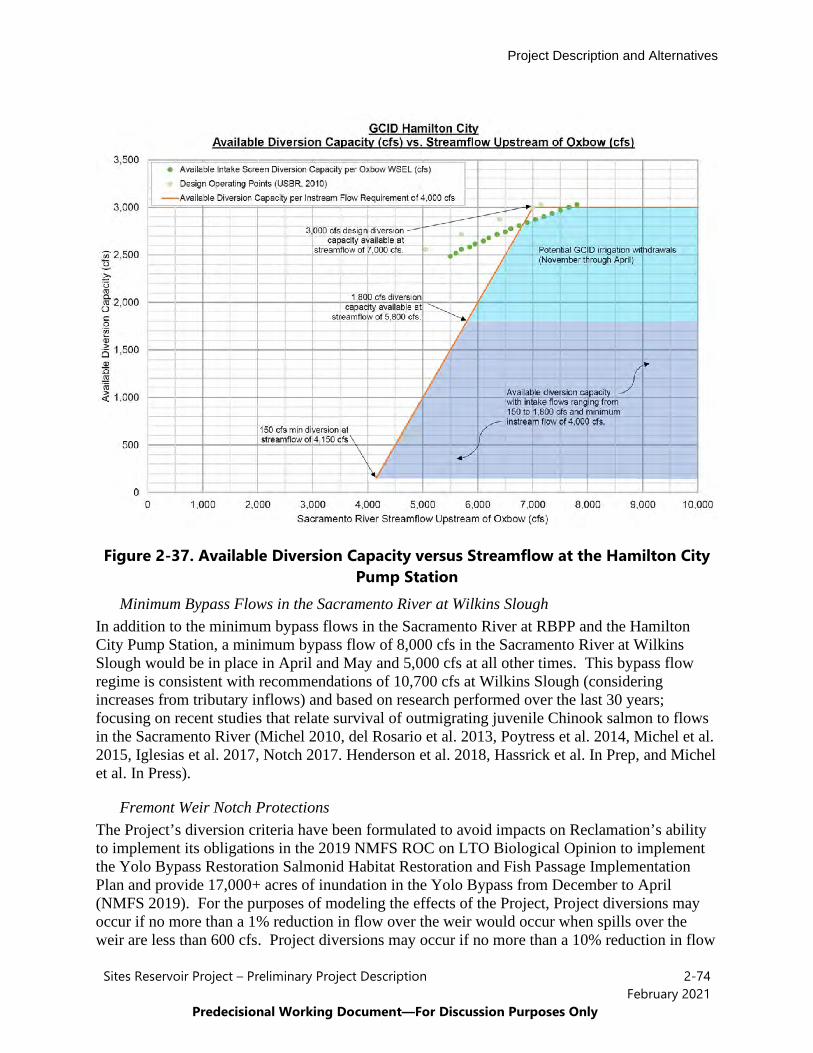
Project Description and Alternatives
Sites Reservoir Project – Preliminary Project Description 2-74February 2021
Predecisional Working Document—For Discussion Purposes Only
Figure 2-37. Available Diversion Capacity versus Streamflow at the Hamilton City Pump Station
Minimum Bypass Flows in the Sacramento River at Wilkins Slough In addition to the minimum bypass flows in the Sacramento River at RBPP and the Hamilton City Pump Station, a minimum bypass flow of 8,000 cfs in the Sacramento River at Wilkins Slough would be in place in April and May and 5,000 cfs at all other times. This bypass flow regime is consistent with recommendations of 10,700 cfs at Wilkins Slough (considering increases from tributary inflows) and based on research performed over the last 30 years; focusing on recent studies that relate survival of outmigrating juvenile Chinook salmon to flows in the Sacramento River (Michel 2010, del Rosario et al. 2013, Poytress et al. 2014, Michel et al. 2015, Iglesias et al. 2017, Notch 2017. Henderson et al. 2018, Hassrick et al. In Prep, and Michel et al. In Press).
Fremont Weir Notch Protections The Project’s diversion criteria have been formulated to avoid impacts on Reclamation’s ability to implement its obligations in the 2019 NMFS ROC on LTO Biological Opinion to implement the Yolo Bypass Restoration Salmonid Habitat Restoration and Fish Passage Implementation Plan and provide 17,000+ acres of inundation in the Yolo Bypass from December to April (NMFS 2019). For the purposes of modeling the effects of the Project, Project diversions may occur if no more than a 1% reduction in flow over the weir would occur when spills over the weir are less than 600 cfs. Project diversions may occur if no more than a 10% reduction in flow

Project Description and Alternatives
Sites Reservoir Project – Preliminary Project Description 2-75February 2021
Predecisional Working Document—For Discussion Purposes Only
over the weir would occur when spills over the weir are between 600 cfs and 6,000 cfs. When flows over the Fremont Weir are greater than 6,000 cfs there would be no restriction on Project diversions. These limitations are intended to reduce changes to spill frequency and duration.
Freeport, Net Delta Outflow Index, X2, and Delta Water Quality For lower Sacramento River and Delta locations, the Project would operate in a manner that would not adversely affect the ability of others to meet all applicable laws, regulations, biological opinions and incidental take permits, and court orders in place at the time that diversion occurs.
Storage in Sites Reservoir Water would be stored in Sites Reservoir until requested for release by a Sites Storage Partner. The Authority would prepare a Reservoir Management Plan that would describe the management of water resources in Sites Reservoir which would include a plan for monitoring water quality (see Section 2.5.2.4 for more information on the Reservoir Management Plan).
Releases from Sites Reservoir Releases from Sites Reservoir would be made in any water year type to meet the needs of the Sites Storage Partners, including the water supply related environmental benefits under WSIP. The releases would be made from the I/O Works in Sites Reservoir and conveyed via pipeline to either Funks Reservoir or the TRR. Under normal operating conditions, 2,000 cfs would be released from the I/O Works to Funks Reservoir and 1,000 cfs would be released from the I/O Works to the TRR. The I/O Works would allow withdrawal of water from Sites Reservoir over a range of depths to manage release water temperatures.
From Funks Reservoir or the TRR, releases would be conveyed as follows:
• Release for Sites Storage Partners Along the TC Canal and the GCID Main Canal –Releases would be made to Funks Reservoir or the TRR and conveyed to the respectiveSites Storage Partner via the existing TC Canal and GCID facilities.
• Releases for Sites Storage Partners Along the Sacramento River – Releases for SitesStorage Partners along the Sacramento River would generally be made via exchange aswater from Sites Reservoir cannot be physically conveyed to any Sites Storage Partner onthe Sacramento River between the GCID Hamilton City Pump Station and KnightsLanding. Real-time exchanges, primarily with GCID, but also with Reclamation wouldbe used for these Sites Storage Partners.
• Releases for Sites Storage Partners Along the CBD, Yolo Bypass, and North BayAqueduct – Releases for Sites Storage Partners, including some of the Proposition 1water, would be made to Funks Reservoir. This water would then be conveyed down theTC Canal to the new Dunnigan Pipeline and released into the CBD. The water wouldthen be conveyed down the CBD, through the Knights Landing Ridgecut, to the YoloBypass/Cache Sough Complex for Proposition 1 benefits or for diversion into the NorthBay Aqueduct.
Project Description and Alternatives
Sites Reservoir Project – Preliminary Project Description 2-76February 2021
Predecisional Working Document—For Discussion Purposes Only
• Releases for Sites Storage Partners South-of-Delta – Releases for Sites StoragePartners who are located south of the Delta, including water for Incremental Level 4Refuge water supply benefits under WSIP, can take a combination of different pathsunder all Action Alternatives. Releases could be made to Funks Reservoir, conveyeddown the TC Canal to the new Dunnigan Pipeline and released into the CBD. This waterwould then be conveyed down the CBD, through the Knights Landing Ridgecut, to theYolo Bypass/Cache Sough Complex and into the North Delta. Once in the Delta, thiswater could be diverted at any of the South Delta pumping facilities (SWP’s BanksPumping Plant, Reclamation’s Jones Pumping Plant or Rock Slough Pumping Plant, orContra Costa Water District’s pumping plants) and conveyed to the respective SitesStorage Partner using existing conveyance facilities and mechanisms. Alternatively, oncereleases are in the CBD, they could be conveyed to the Sacramento River via the KnightsLanding Outfall Gates. Once in the Sacramento River, these releases would enter theDelta and could be diverted at any of the South Delta pumping facilities. Releases forSites Storage Partners who are located south of the Delta, including water for IncrementalLevel 4 Refuge water benefits under WSIP, may also be made by exchanges withReclamation and DWR. Releases for Sites Storage Partners south-of-Delta wouldgenerally be made during July to November to coincide with available pumping capacityat the South Delta pumping facilities and would be subject to applicable laws,regulations, biological opinions and incidental take permits, and court orders in place atthe time.
Releases would be coordinated with Reclamation and DWR to ensure there are no conflicts with CVP and SWP operations and no adverse effects to the CVP and SWP. In addition, releases would be coordinated with Reclamation and DWR to ensure that there is available capacity to redivert releases at the South Delta pumping facilities for any releases that would be pumped at these locations. The majority of releases to the Sacramento River would occur when the CVP and SWP are in balanced conditions, that is releases from upstream reservoirs and unregulated flow approximately equal water supply needed to meet Sacramento Valley in-basin uses and CVP and SWP exports.
Sites Reservoir is currently estimated to have a dead pool of approximately 17,700 AF, below which water cannot physically be removed from the reservoir using the I/O Works. However, the Authority is currently planning to operate to a dead pool of 120,000 AF under normal conditions. The operational dead pool amount may be revised and reduced in final design. Sites Reservoir may also be drawn down below the operational dead pool in drought situations.
Coordination with CVP and SWP Operations of all Action Alternatives would be coordinated with Reclamation and DWR to prevent conflicts with the CVP and SWP operations or add additional obligations on the CVP or SWP to meet applicable laws, regulations, biological opinions and incidental take permits, and court orders in place at the time. The Authority is currently working with Reclamation and DWR to establish operating agreements with both agencies that would describe the details of the coordination and collaboration that would take place in the operations of the Project.
Project Description and Alternatives
Sites Reservoir Project – Preliminary Project Description 2-77February 2021
Predecisional Working Document—For Discussion Purposes Only
It is expected that the Project would also be incorporated into existing and future technical and advisory teams in which Reclamation and DWR participate in to coordinate the CVP and SWP operations with the regulatory agencies. This could include, but would not be limited to, the Sacramento River Temperature Task Group and Delta Operations for Salmon and Sturgeon Group. This would allow for better and more efficient coordination of the Project’s operations, in concert with the CVP and SWP operations, with the regulatory agencies along with providing opportunities to work collaboratively to achieve species benefits in the Sacramento Valley and the Delta.
All of the Action Alternatives also include the possibility of exchanges of water with the CVP and SWP. Exchanges have the potential to assist the CVP and SWP in meeting their regulatory obligations. Exchanges are expected to primarily occur with Shasta Lake and Lake Oroville, but could also occur with Folsom Lake and real-time with local participants. Exchanges would only be conducted when they would be neutral or beneficial to CVP and SWP operations and not impact the ability of the CVP or SWP to meet applicable laws, regulations, biological opinions and incidental take permits, and court orders in place at the time. Exchanges are described in more detail below.
• Shasta Lake Exchanges – Exchanges under the Project with Shasta Lake would beformulated to target cold-water pool preservation and anadromous fish benefits. ShastaLake exchanges would occur in years when forecasted temperature-based mortality ofearly life stage winter-run Chinook salmon would be reduced if the exchange is in place.Under a Shasta Lake exchange, water would be released from Sites Reservoir in thespring to meet CVP purposes, including CVP water service and/or repayment contractorsin the Sacramento Valley that could physically receive water from Sites Reservoir. Byreducing releases from Shasta Lake in the spring, storage and the cold-water pool inShasta Lake would be preserved for use later in the year, typically during critical monthsof the cold-water pool management season (August and September). In late-summer andfall (i.e., August through November), Reclamation would release an equivalent amount ofwater from Shasta Lake for Sites Storage Partners. All exchange water would be releasedfrom Shasta Lake in late summer and fall and no exchanged water would be carried overfrom year to year.
• Lake Oroville Exchanges – Exchanges under the Project with Lake Oroville would beformulated to facilitate Sites Project deliveries to Sites Storage Partners and refuges southof the Delta and may also improve cold-water pool conditions at Lake Oroville.Exchanges with Lake Oroville are expected to happen more frequently and would bedriven by a variety of factors. Under a Lake Oroville exchange, water would be releasedfrom Sites Reservoir primarily in June and July to meet SWP purposes. By reducingreleases from Lake Oroville in these months, storage and the cold-water pool in LakeOroville would be preserved for use later in the year, typically during critical months ofthe cold-water pool management season (August and September). In late-summer and fall(i.e., August through November), DWR would release an equivalent amount of waterfrom Lake Oroville for Sites Storage Partners. All exchange water would be releasedfrom Lake Oroville in late summer and fall and no exchanged water would be carriedover from year to year.

Project Description and Alternatives
Sites Reservoir Project – Preliminary Project Description 2-78February 2021
Predecisional Working Document—For Discussion Purposes Only
• Folsom Lake Exchanges – Exchanges with Folsom Lake would be operated similarly toexchanges with Shasta Lake. Sites Reservoir would release water in the spring and earlysummer to meet CVP purposes in lieu of Reclamation releases at Folsom Lake. Anequivalent amount of water would then be released from Folsom Lake in the late summerand fall for Sites Storage Partners. All exchange water would be released from FolsomLake in late summer and fall and no exchanged water would be carried over from year toyear.
• Real-Time Exchanges with Local Participants – To support timing of releases anddeliveries to Sites Storage Partners north and south of the Delta, in-lieu exchanges withlocal participants may occur. This type of exchange is most likely to occur with GCID,but could also occur with Sacramento River Settlement Contractors and Reclamation.Instead of diverting all of its CVP supply from the Sacramento River, the contractorwould receive a portion of its CVP supply from Sites Reservoir. A portion of the waterreleased from Shasta Lake to meet the contractor’s CVP supply would be left in theSacramento River (not diverted by the contractor) and used for other Sites StoragePartners.
Funks Creek and Stone Corral Creek Releases The Project includes releases from Sites Reservoir into both Funks and Stone Corral Creeks. These releases would be made to comply with California Fish and Game Code Section 5937 and ensure no harm to downstream water right holders on these creeks. At this time, access to the creeks is restricted and there is not sufficient existing information on these two creeks, including current fish assemblage, channel capacity, and existing habitat, to determine a specific release pattern or approach to releases into these two creeks. Field studies would be conducted once access is obtained and before final design for Sites and Golden Gate Dam is completed to determine the following:
• Existing fish assemblage in these creeks, including fish species presence and habitat use;• Characterization of habitats available (e.g., spawning, rearing, foraging, and sheltering
habitats) at varying flow levels;• Characterization of flows, including assessing the base flow during the summer months;• Conducting a fluvial geomorphologic study to characterize bed load and flow levels
necessary for mobilization; and• Hydrological studies to define flow temperature relationships.
Using information from these field studies, along with currently available information, the Authority would prepare a Funks and Stone Corral Creeks Operations Plan that would identify the approach for releases, including release schedule and volumes, a monitoring plan, and an adaptive management plan to maintain fish in good condition consistent with California Fish and Game Code Section 5937. Releases into these creeks need to be made in consideration of the flood control benefits of the Project and in such a way as to not overtop the stream banks and flood downstream areas.
Project Description and Alternatives
Sites Reservoir Project – Preliminary Project Description 2-79February 2021
Predecisional Working Document—For Discussion Purposes Only
Water released into Funks Creek would be made through the transition manifold at the base of Golden Gate Dam and a new pipeline that terminates at Funks Creek below Golden Gate Dam. These facilities are currently being designed to carry up to 100 cfs with a release range of 0 to 100 cfs into Funks Creek. Water released into Stone Corral Creek would be made through the permanent outlet at Sites Dam. This outlet is currently being designed with a release range of 0 to 100 cfs, with an emergency release capacity of up to 2,500 cfs.
Flood Control All Action Alternatives would provide flood damage reduction benefits to the communities of Maxwell and Colusa, local agricultural lands and rural homes and I-5 by impounding Funks Creek and Stone Corral Creeks. These flood control benefits are inherent in the design of the Project and no specific operational criteria are necessary to achieve these benefits.
Emergency Release All Action Alternatives include the design and operation of facilities to meet DSOD criteria and requirements for emergency reservoir drawdown. During an emergency release event, Saddle Dams 3 and 5 (Alternative 1 and 3) and Saddle Dam 8B (all Action Alternatives), the I/O Works, and Sites Dam would operate simultaneously to release water. Once the water level fell below the levels of the saddle dam intakes, the I/O Works and Sites Dam would operate solely to release the remaining water. The emergency releases would be in accordance with DSOD requirements and would occur as follows:
• Under Alternative 1 and 3 only, the emergency release structures at Saddle Dams 3 and 5,located at the north end of the reservoir, would release water into the Hunters Creekwatershed. These two structures could only be used during the emergency drawdown inthe first 7 days, at a rate of 1,000 and 1,200 cfs, until the water level fell below theiroutlet.
• Under All Action Alternatives, the spillway on Saddle Dam 8B would also release toHunters Creek. The size of the spillway would accommodate the peak outflow of a PMFevent or the steady-state flow if an over-pumping event occurred. The design and size ofthe spillway assumed that a PMF overflow event and an over-pumping event have a verylow probability of simultaneous occurrence.
• The permanent outlet on Sites Dam would release to Stone Corral Creek at a maximumrate of approximately 2,500 cfs.
• The I/O tunnels would release to Funks Reservoir and TRR at a rate of 16,000 cfs, with9,000 cfs being discharged to Funks Reservoir and 7,000 cfs to the TRR with a maximumvelocity of 40 feet per second in the pipelines. To achieve the flows needed for theemergency releases, the velocities in the pipes would exceed the 20 cfs criteria normallyused by Reclamation. Discharges to the Funks Reservoir would be accommodatedbecause its spillway is designed for 22,000 cfs which is greater than the 16,000 cfsemergency drawdown flow. The TRR would need to be designed with a spillway intoFunks Creek of roughly 7,000 cfs to allow for this. Additional energy dissipationstructures at Funks Reservoir and the TRR would be required for the emergency flows.

Project Description and Alternatives
Sites Reservoir Project – Preliminary Project Description 2-80February 2021
Predecisional Working Document—For Discussion Purposes Only
2.5.2.2 Energy Generation and Energy Use All Action Alternatives would require power to run facilities and pump water and would also generate incidental power. The pumping energy requirements and power generation are summarized in Table 2-6 and Table 2-7 for all Action Alternatives.
Table 2-6. Pumping Summary for All Action Alternatives
Site Net Pumping Power (MW)
Other Auxiliary Loads (MW)
Transformer and T Line Losses (MW)
Total Pumping Power (MW)
Total Pumping Power @ 0.85 PF (MVA)
Funks 67.1 1 0.1 68.2 80.2 TRR 75.4 1 0.1 76.5 90.0 Total 142.5 2 0.2 144.7 170.2
Notes:
MW = megawatts; PF = power factor; MVA = megavolt amperes
Table 2-7. Generating Summary for All Action Alternatives
Site
Net Generating Power (MW)
Other Auxiliary Loads (MW)
Transformer and T Line Losses (MW)
Total Power Generation (MW)
Total Power Generation @ 0.85 PF (MVA)
Funks 48.1 1 0.1 47.0 55.3 TRR 27.4 1 0.1 26.3 31.0 Total 75.5 2 0.2 73.3 86.2
Notes:
MW = megawatts; PF = power factor; MVA = megavolt amperes
All Action Alternatives would generate incidental power only when water is released from Sites Reservoir at the Funks and TRR PGPs. Power generation would be limited to 40 megawatts per facility and as such, would not require a Federal Energy Regulatory Commission license per the “Qualifying Conduit Hydropower Facility” under the Hydropower Regulatory Efficiency Act of 2013, as amended by America’s Water Infrastructure Act of 2018. All Action Alternatives would include electrical substations at Funks Reservoir and the TRR. These substations would service a net pumping energy demand estimated at 80 megavolt amperes (MVA) at Funks Reservoir and 90 MVA at the TRR (i.e., 170 MVA of demand load total). Because of the size of the pumping units, no backup generation is planned for pumping facilities.
While hydropower generation would be an incidental benefit of conveying water through specific Project facilities and would be influenced by the timing of releases and movement of water and seasonal operational decisions, the Authority would work to schedule releases and outages such that it sought to maximize power generation to offset the Project’s power needs. Additional operations power needs beyond those generated by the Project would be purchased from market sources, with a target of purchasing at least 60% of the Project’s operations power needs from renewable, carbon-free sources from the start of operations to 2045. Starting in
Project Description and Alternatives
Sites Reservoir Project – Preliminary Project Description 2-81February 2021
Predecisional Working Document—For Discussion Purposes Only
2045, the Authority would target purchasing 100% of the Project’s operations power needs from renewable, carbon-free sources. This target does not include any operational power needs attributable to Reclamation’s participation, including the conveyance and pumping of Incremental Level 4 Refuge water supply.
2.5.2.3 Facility Operations and Maintenance Operations and maintenance activities for all facilities, including recreational areas, would include debris removal, vegetation control, rodent control, erosion control and protection, routine inspections (dams, tunnels, pipelines, PGPs, I/O Works, fencing, signs, and gates), painting, cleaning, repairs, and other routine tasks to maintain the facilities in accordance with design standards after construction and commissioning. Routine visual inspection of the facilities would be conducted to monitor performance and prevent mechanical and structural failures. The Authority would implement operations and maintenance BMPs that are described in Section 2.5.4, Project Commitments and Best Management Practices Common to All Alternatives.
The RBPP has an established operations and maintenance plan. The two new pumps at the facility would be incorporated into the existing plan and operated and maintained as part of the overall activities at the facility. Improvements to the GCID facilities would likewise be incorporated into GCID’s regular operations and maintenance activities.
Operations and maintenance activities unique to the TRR include daily visual inspections, setting and checking water control structures, annual and five-year dam safety inspections, quarterly vegetation and weed abatement and rodent control, annual preventative leak location surveys and evaluations of the reservoir liner, instrumentation monitoring and maintenance, and annual debris removal at the spillway outfall to Funks creek. Replacement of the TRR liner may be needed on an infrequent basis. Operations and maintenance activities unique to the TRR and Funks pumping plants and hydroelectric turbines would include greasing, painting, oiling, and generally keeping the pumps in good operating condition. Activities would also include annual inspections of pumps, interior coating condition inspection, pump leakage inspections, temperature and pressure checks, and clean exterior surfaces and check for leaks. Repair and replacement of pump components would be needed on a periodic basis. Monthly brake airline filter and lubricator inspection and maintenance would also be completed at the hydroelectric turbines. Energy dissipating units would be visually inspected and lubrication of bearings would be conducted on an as needed basis.
Operations and maintenance activities unique to the electrical switchgear include visual and mechanical inspections, moisture and corrosion inspections, general wiring checks, and insulator and barrier checks. A series of tests would be conduction on regular intervals, including but not limited to insulation electrical test, control wiring electrical tests, circuit breakers and switch tests, system function tests, and surge arrestor tests. Electrical switchgear would be maintained, repaired or replaced as needed to continue safe and efficient operations.
Pipelines and tunnels would be inspected at least every 5 years and remote operated vehicle (ROV) inspections would be acceptable. ROV inspections would not require dewatering the tunnels or pipelines. If physical inspections of tunnel interiors would be required, the tunnels would be completely shut down. Tunnel inspections may be completed during normally
Project Description and Alternatives
Sites Reservoir Project – Preliminary Project Description 2-82February 2021
Predecisional Working Document—For Discussion Purposes Only
scheduled shutdowns when water is not being conveyed in or out of the reservoir. The tunnel shutdown duration could run from a few days (inspection) to 2 weeks (if maintenance is required).
Different components of the I/O Works would need to be inspected and maintained at varying frequencies. Any port gate that was not operated in a given year based on reservoir level would be functionally tested at least once during that year. In general, pipeline appurtenances (e.g., air/vacuum valves, blowoffs) would be inspected and functionally tested where possible annually. Most of the mechanical components in the multi-level I/O tower could be functionally tested and/or maintained without requiring a shutdown (as there would be multiple tiers from which to draw water).
Maintenance of access roads includes replacing gravel or scraping and filling of ruts to keep the roads in good condition along with pavement replacement and repair for paved roads. Minor structures maintenance includes repair or replacement of gates, locks or fences, painting gates, replacing lost or damaged signage, and lubricating gates.
Maintenance of lands could include grading fire breaks/trails, maintaining vegetation (e.g., grazing, tilling, or disking), and performing limited prescribed/controlled burns.
In general, operations and maintenance activities could occur on a daily, annually, periodically (as needed), and long-term basis. It is estimated that 45 operations and maintenance workers would be needed to perform operations and maintenance activities (based on three shifts per day, 365 days a year).
2.5.2.4 Operations and Management Plans The Authority would develop and implement a number of operations and management plans to govern the operations and maintenance activities of Project. These plans are described below.
Reservoir Operations Plan The Reservoir Operations Plan would describe the management of water operations, including releases into Funks and Stone Corral Creeks. This plan would include but may not be limited to the following:
• Diversions to Sites Reservoir – Mechanics on how diversions are scheduled andmanaged, including diversion criteria and operating requirements for diversions.
• Storage in Sites Reservoir – How losses and evaporation are accounted for, howexchanges and transfers are managed (both between Sites Storage Partners and with non-Sites Storage Partners), and the process for leasing or sharing storage space.
• Releases from Sites Reservoir – When and how water can be released to each facility,how release orders are made and adjusted, and how releases are prioritized whennecessary.
• Flows in Funks and Stone Corral Creeks – Release operations for releases into Funksand Stone Corral Creeks.

Project Description and Alternatives
Sites Reservoir Project – Preliminary Project Description 2-83February 2021
Predecisional Working Document—For Discussion Purposes Only
• Flood Control and Health and Safety Considerations – Descriptions of howemergencies should be handled and processes for notification in the event ofemergencies. Emergency flow releases will be addressed in an Emergency Action Plan.
A draft of the Reservoir Operations Plan is expected to be completed in late 2021, with additional refinements and subsequent drafts as operational components are finalized (such as final permit conditions and agreements with Reclamation and DWR are completed). A complete Reservoir Operations Plan would be prepared at least one year prior to Project operations being initiated.
Reservoir Management Plan The Reservoir Management Plan would describe the management of water resources within Sites Reservoir. This plan would include but may not be limited to the following:
• Fisheries Management – Target fisheries species composition and managementactivities for Sites Reservoir, including stocking strategies (if any), habitat enhancementmeasures, and monitoring efforts.
• Reservoir Water Quality – Baseline water quality metrics, standards, testing andmonitoring protocols.
• Vector Management – Protocols and practices for communicating/coordinating withvector control authorities and determining how vector control would be managed at SitesReservoir and the TRR.
The Reservoir Management Plan would be completed at least one year prior to Project operations being initiated.
Land Management Plan The Land Management Plan would describe the management and maintenance activities on all non-recreation land resources held in fee or easement by the Authority. This plan would include management actions for buffer areas and the specific type and frequency of maintenance activities by location. Land management, maintenance, and monitoring actions for any mitigation areas owned by the Authority would also be described. The Land Management Plan would be completed within a year of the first fee title acquisition by the Authority and would be amended as needed as additional lands are acquired.
Recreation Management Plan The Recreation Management Plan would describe the types, management, maintenance and monitoring activities on all Project recreation lands and areas. Development of the Recreation Management Plan would be coordinated with Colusa and Glenn counties and the local police, fire, and emergency response entities and organizations to ensure appropriate emergency response resources are available to respond to recreation emergencies. The Recreation Management Plan would be completed at least one year prior to the opening of Project recreational facilities.
Project Description and Alternatives
Sites Reservoir Project – Preliminary Project Description 2-84February 2021
Predecisional Working Document—For Discussion Purposes Only
Initial Reservoir Fill Plan The Initial Reservoir Fill Plan would describe the monitoring program for Sites and Golden Gate Dams along with the saddle dams, saddle dikes, and areas around the reservoir that would be implemented during the initial filling of Sites Reservoir. The Initial Reservoir Fill Plan would be completed as part of the DSOD approval process and would be completed at least one year prior to beginning to fill Sites Reservoir.
Standard Operating Procedures The Authority would prepare Standard Operating Procedures for all major Project facilities. These Standard Operating Procedures would include operational guidelines for facilities along with a schedule for inspection, monitoring and maintenance. The Standard Operating Procedures are expected to be completed as part of the DSOD approval process and would be completed prior to beginning operations of the specific Project facility.
Security Plan The Authority would prepare a Security Plan for all major Project facilities. Preparation of the Security Plan would be coordinated with local, state, and federal law enforcement agencies to ensure a comprehensive security review and assessment along with appropriate security measures implemented for all major Project facilities. The Security Plan is expected to be completed as part of the DSOD approval process and would be completed during final design.
Emergency Action Plan Consistent with California Water Code sections 6160, 6161, and 6002.5, an Emergency Action Plan would be prepared and submitted to the Governor’s Office of Emergency Services (CalOES). The Emergency Action Plan would comply with SB 92 and CalOES’s Emergency Action Plan requirements. The Emergency Action Plan would include, but may not be limited to the following: summary of responsibilities; notification procedures and flowchart; emergency response process; preparedness for different emergencies; and potential inundation mapping. The Emergency Action Plan would also identify the frequency for desktop and full exercises to prepare for emergencies.
2.5.3 Construction Considerations Common to All Action Alternatives This section summarizes the activities associated with construction of the Project. Appendix 2C, Construction Means, Methods, and Assumptions, provides additional detail regarding the construction means and methods for various facilities that are ultimately incorporated into the impact analysis throughout Chapters 5 to 31 of this document.
2.5.3.1 Geotechnical Investigations To support the engineering and final design of all facilities, the Authority would undertake preconstruction geologic, geotechnical, and geophysical investigations and testing. These geotechnical investigations and associated testing would also be required to support DSOD permitting processes. The investigations would be implemented in various locations in and around the footprints of the various facilities. Proposed investigations would be focused in areas where additional or updated data are needed for engineering cost refinement, for design, and to prepare permit applications. Depending on the time of year these activities would take place,

Project Description and Alternatives
Sites Reservoir Project – Preliminary Project Description 2-85February 2021
Predecisional Working Document—For Discussion Purposes Only
almost all of the geotechnical borings and geophysical work areas would require biological monitoring and/or some pre-activity clearance assessment and/or surveys due to their proximity to sensitive biological resources, particularly because the precise location of each individual investigation within its associated project feature has not been determined. The site-specific geotechnical investigations would include surface geologic mapping and surface and subsurface geophysical investigations as described below.
• Surface geologic mapping would generally involve noninvasive evaluation anddocumentation of geologic features and topography and would consist of soil mapping,walking surveys, and geophysical surveys.
• Surface geophysical investigations would generally involve non- or minimally invasivesurface testing, such as seismic, gravitational, magnetic, electrical, and electromagnetictesting, and documentation of surface and subsurface site characteristics.
• Subsurface geotechnical investigations would involve surface and subsurface evaluationand documentation of site characteristics using test pits, borings and cone penetration test(CPT) probes, and fault trenching for different facilities.
o All subsurface geotechnical investigation techniques would require some degree ofground disturbance, including spot leveling of areas directly below truck levelingjacks and holes measuring 2 to 10 inches in diameter through which augers andsampling equipment would be lowered to collect subsurface data and samples. Somedrilling locations would require a bulldozer to create temporary roads for drill rigaccess. Test pits would be roughly 10 to 12 feet deep, and fault trenching would varyroughly 10 to 30 feet deep.
o Borehole drilling would be performed using a drill rig that utilizes a combination ofpilot bit, hollow stem flight augers, and rotary diamond core drilling. The hollowstem augers would likely have 8.5-inch outer diameter, and 4.25-inch inner diameter,with a 5-foot-long split tube inner barrel for dry core sample collection. StandardPenetration Test samplers may also be used at 5-foot intervals. All drill cuttings andany drilling fluids would be contained onsite in drums or bins and removed from thesite to an existing permitted landfill or waste treatment facility. The temporarydisturbance area would be approximately 20 by 50 feet (0.025 acre). Once eachboring is complete, augers and testing equipment would be removed, the boringgrouted and capped with soil, and the area cleared of work items (as required bypermit requirements and at a minimum in accordance with California regulations andindustry standards [Water Well Standards, DWR 74-81 and 74-90]). The permanentdisturbance area would be approximately 1 square foot per borehole, except where abulldozer created a larger area to access some locations.
o CPTs are minimally invasive and consist of a specialized vehicle that inserts a 1.7-inch-diameter cone (probe) into the ground with a hydraulic direct push system. Thetemporary disturbance area would be approximately 20 by 50 feet (0.025 acre). Onceeach test is complete the rod would be retracted, the hole grouted and capped withsoil, and the area cleared of work items (as required by permit requirements and at aminimum in accordance with California regulations and industry standards [Water
Project Description and Alternatives
Sites Reservoir Project – Preliminary Project Description 2-86February 2021
Predecisional Working Document—For Discussion Purposes Only
Well Standards, DWR 74-81 and 74-90]). The permanent disturbance area would be approximately 1 square foot per borehole.
Activities at most investigation areas would require approximately five personnel, including a driller/operator and one to two assistants, a utility locator, and a geologist/engineer to log the conditions encountered. Biological and cultural monitoring could also be required based on biological and cultural sensitivity and the type of activity being conducted. Each geotechnical investigation site would be active for a period ranging from 1 workday for CPT probes to 10 workdays for deep drill holes.
Additional details regarding geotechnical investigations for several of the key facilities are discussed below.
I/O Works The investigation footprint for the I/O Works would encompass the area around each portal, at the I/O tower, and along each tunnel alignment. Geotechnical work would occur within the footprint of the construction area for these facilities. It is assumed that a boring would be required every 500 feet between the two I/O tunnel alignments and that each boring would extend two tunnel diameters below the tunnel invert, for a depth of approximately 70 feet.
A seismic fault study would map the faults adjacent to the I/O Works and ensure the location of the alignment would minimize fault crossings. The geotechnical investigation footprint for the seismic fault study would encompass the area between the mapped faults and I/O Works.
Current access to the site is limited given the existing topography and lack of access roads. It is assumed that track-mounted drill rigs would be used for the accessible locations and helicopters would be required to transport drill rigs to remote locations.
Dams and Reservoir The dam foundations and reservoir rim would be the subject of specific geotechnical investigations. The investigations for the dams would involve geologic mapping, geophysics, borings, test pits, test excavations, and fault trenching. In-situ testing would include downhole geophysics (suspension and televiewer), packer testing, and dilatometer use. Piezometers would be installed at select locations to collect data on groundwater depth.
Objectives for the dam foundation and reservoir rim would differ. The objectives of the dam foundation exploration would be to evaluate excavation methods, excavated material use for dam construction, dewatering requirements for foundation excavation, foundation deformability, hydraulic conductivity and strength, foundation treatment, and foundation grouting/cutoff requirements. The dam foundation exploration objectives would also be to confirm fault locations and fault rupture potential. The objective of the exploration of the reservoir rim would be to evaluate seepage and stability. This investigation would use geologic mapping, geophysical investigations, and borings. In-situ testing would include downhole geophysics (televiewer) and packer testing.
Project Description and Alternatives
Sites Reservoir Project – Preliminary Project Description 2-87February 2021
Predecisional Working Document—For Discussion Purposes Only
Laboratory testing for the dam foundation and reservoir rim may include point load and unconfined compression on rock and index testing of soils. Laboratory testing for the rim of the reservoir may also include testing of remolded joint/shear material for strength evaluation.
Onsite Borrow Areas The onsite borrow areas would have specific geotechnical investigations.
The objectives of the exploration for the borrow areas would be to confirm that the volume of materials available is at least 1.5 times the volume required and to evaluate excavation methods, excavation slopes at borrow locations, dewatering for borrow excavations, volume of materials generated from excavation, material types generated by excavation, requirements for processing of materials, properties of materials when placed and compacted in the dams, use of rock for riprap and aggregates, and types and volumes of materials generated from required excavations (i.e., at proposed locations of dams, structures, and tunnels).
The investigations for the borrow areas would involve geologic mapping, geophysics, borings, test pits, test excavations, test blasting and test fills. In-situ testing would include downhole geophysics (suspension and televiewer) and rippability studies. Laboratory testing would include point load and unconfined compression on rock and index testing of soils. Laboratory testing would also involve testing remolded samples for compaction, strength, permeability, compressibility, and erosion potential. Test fills would be performed on rockfill and random fill materials.
2.5.3.2 Land Acquisition and Resident Relocation Program Prior to initiation of construction activities, land acquisition or establishment of temporary or permanent easements on private properties would be required. Overall, construction is expected to take approximately 6 years for reservoir facilities and 2 years for conveyance facilities. Construction of the reservoir facilities and the conveyance facilities would be conducted concurrently for a total construction duration of 6 years. Several factors could affect this anticipated schedule. Additional adjustments to the schedule would be addressed as required during Project development and implementation.
2.5.3.3 Additional Biological Surveys After land acquisition and prior to construction actions, the Authority would complete additional biological surveys to confirm mapped habitat types and determine the presence/absence of biological resources including, but not limited to, special-status species, state and federal waters, sensitive plant communities and other applicable resources identified as sensitive by state, and/or federal agencies and discussed in Chapter 9, Vegetation Resources; Chapter 10, Wildlife Resources; and Chapter 11, Aquatic Biological Resources of this document. The Authority would use this information to assess the need for further technical studies (such as protocol surveys) and/or consultations with USFWS, CDFW, U. S. Army Corps of Engineers and/or State and Regional Water Quality Control Boards and identify resources that would be avoided during construction. In addition, the Authority would use this information to determine final mitigation types and acres for those areas that cannot be avoided.
Project Description and Alternatives
Sites Reservoir Project – Preliminary Project Description 2-88February 2021
Predecisional Working Document—For Discussion Purposes Only
2.5.3.4 Cultural Resources Management Plan The Authority will develop and implement a Cultural Resources Management Plan prior to construction activities to guide the overall technical cultural resources efforts during construction activities. The Cultural Resources Management Plan will include, but not be limited to, a research design for the evaluation of known and predicted resources in the study area, methods used to assess the Project’s effects to resources found prior to and during construction, procedures for the curation of recovered materials, procedures to be followed in the event of unanticipated discoveries, and procedures for the recovery and treatment of Native American and Non-Native American human remains. The Cultural Resources Management Plan is expected to be reviewed by the signatory parties to the Project’s Programmatic Agreement under Section 106 of the National Historic Preservation Act.
2.5.3.5 Cemetery Relocation Two private cemeteries in the inundation area would be relocated to a site approved for interment of human remains per requirements of the California Health and Safety Code (HSC § 7500-7527). The code requires a written order from the local health department or county superior court before human remains in a cemetery may be moved. The disinterment, transportation, and removal of human remains is subject to rules and regulations adopted by the board of health or health officer of the county.
2.5.3.6 Construction Disturbance Areas and Access Construction activities would be confined to designated construction disturbance areas. These areas would also be used for construction vehicle and equipment parking and construction material storage. Special or sensitive sites near construction disturbance areas would be clearly marked (e.g., with temporary fencing, staking and flagging, pylons) prior to construction initiation. Construction personnel would be trained to recognize these markers and understand the equipment movement restrictions involved. Marking materials would be maintained until final cleanup and/or site restoration is completed, after which they would be removed. Potential staging areas would be located near each of the facilities. Construction-related traffic and local access routes are described in Section 2.5.1.7, New and Existing Roadways.
Demolition Demolition would take place within the reservoir inundation area once lands are acquired. Demolition would include 20 houses, 25 barns, and 40 other structures (i.e., sheds, silos, and pump house); removal of existing septic tanks and other underground storage tanks; and removal of existing roads, fences, and other utilities. Demolition debris would be reused and recycled to the extent possible. Any materials not recyclable would be transported and disposed of at an approved landfill(s).
No demolition or relocation would be required for the TC Canal diversion, TRR-related facilities, Funks Reservoir-related facilities, or facilities associated with conveyance to the Sacramento River (i.e., TC Canal intake, Dunnigan Pipeline, or CBD outlet).
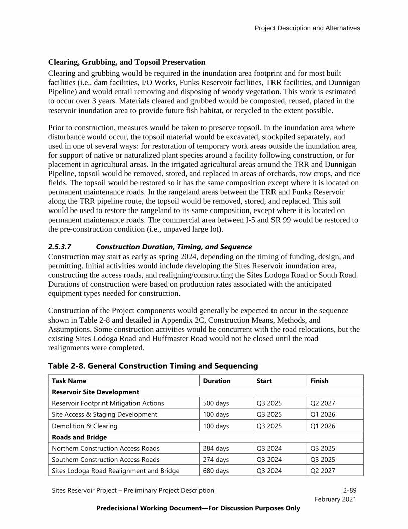
Project Description and Alternatives
Sites Reservoir Project – Preliminary Project Description 2-89February 2021
Predecisional Working Document—For Discussion Purposes Only
Clearing, Grubbing, and Topsoil Preservation Clearing and grubbing would be required in the inundation area footprint and for most built facilities (i.e., dam facilities, I/O Works, Funks Reservoir facilities, TRR facilities, and Dunnigan Pipeline) and would entail removing and disposing of woody vegetation. This work is estimated to occur over 3 years. Materials cleared and grubbed would be composted, reused, placed in the reservoir inundation area to provide future fish habitat, or recycled to the extent possible.
Prior to construction, measures would be taken to preserve topsoil. In the inundation area where disturbance would occur, the topsoil material would be excavated, stockpiled separately, and used in one of several ways: for restoration of temporary work areas outside the inundation area, for support of native or naturalized plant species around a facility following construction, or for placement in agricultural areas. In the irrigated agricultural areas around the TRR and Dunnigan Pipeline, topsoil would be removed, stored, and replaced in areas of orchards, row crops, and rice fields. The topsoil would be restored so it has the same composition except where it is located on permanent maintenance roads. In the rangeland areas between the TRR and Funks Reservoir along the TRR pipeline route, the topsoil would be removed, stored, and replaced. This soil would be used to restore the rangeland to its same composition, except where it is located on permanent maintenance roads. The commercial area between I-5 and SR 99 would be restored to the pre-construction condition (i.e., unpaved large lot).
2.5.3.7 Construction Duration, Timing, and Sequence Construction may start as early as spring 2024, depending on the timing of funding, design, and permitting. Initial activities would include developing the Sites Reservoir inundation area, constructing the access roads, and realigning/constructing the Sites Lodoga Road or South Road. Durations of construction were based on production rates associated with the anticipated equipment types needed for construction.
Construction of the Project components would generally be expected to occur in the sequence shown in Table 2-8 and detailed in Appendix 2C, Construction Means, Methods, and Assumptions. Some construction activities would be concurrent with the road relocations, but the existing Sites Lodoga Road and Huffmaster Road would not be closed until the road realignments were completed.
Table 2-8. General Construction Timing and Sequencing
Task Name Duration Start Finish Reservoir Site Development Reservoir Footprint Mitigation Actions 500 days Q3 2025 Q2 2027 Site Access & Staging Development 100 days Q3 2025 Q1 2026 Demolition & Clearing 100 days Q3 2025 Q1 2026 Roads and Bridge Northern Construction Access Roads 284 days Q3 2024 Q3 2025 Southern Construction Access Roads 274 days Q3 2024 Q3 2025 Sites Lodoga Road Realignment and Bridge 680 days Q3 2024 Q2 2027
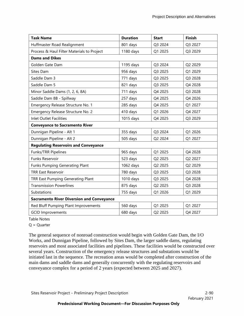
Project Description and Alternatives
Sites Reservoir Project – Preliminary Project Description 2-90February 2021
Predecisional Working Document—For Discussion Purposes Only
Task Name Duration Start Finish Huffmaster Road Realignment 801 days Q3 2024 Q3 2027 Process & Haul Filter Materials to Project 1180 days Q1 2025 Q3 2029 Dams and Dikes Golden Gate Dam 1195 days Q3 2024 Q2 2029 Sites Dam 956 days Q3 2025 Q1 2029 Saddle Dam 3 771 days Q3 2025 Q3 2028 Saddle Dam 5 821 days Q3 2025 Q4 2028 Minor Saddle Dams (1, 2, 6, 8A) 711 days Q4 2025 Q3 2028 Saddle Dam 8B - Spillway 257 days Q4 2025 Q4 2026 Emergency Release Structure No. 1 285 days Q4 2025 Q1 2027 Emergency Release Structure No. 2 410 days Q1 2026 Q4 2027 Inlet Outlet Facilities 1015 days Q4 2025 Q3 2029 Conveyance to Sacramento River Dunnigan Pipeline - Alt 1 355 days Q3 2024 Q1 2026 Dunnigan Pipeline - Alt 2 505 days Q2 2024 Q1 2027 Regulating Reservoirs and Conveyance Funks/TRR Pipelines 965 days Q1 2025 Q4 2028 Funks Reservoir 523 days Q2 2025 Q2 2027 Funks Pumping Generating Plant 1062 days Q2 2025 Q2 2029 TRR East Reservoir 780 days Q3 2025 Q3 2028 TRR East Pumping Generating Plant 1010 days Q3 2025 Q4 2028 Transmission Powerlines 875 days Q2 2025 Q3 2028 Substations 755 days Q1 2026 Q1 2029 Sacramento River Diversion and Conveyance Red Bluff Pumping Plant Improvements 560 days Q1 2025 Q1 2027 GCID Improvements 680 days Q2 2025 Q4 2027
Table Notes Q = Quarter
The general sequence of nonroad construction would begin with Golden Gate Dam, the I/O Works, and Dunnigan Pipeline, followed by Sites Dam, the larger saddle dams, regulating reservoirs and most associated facilities and pipelines. These facilities would be constructed over several years. Construction of the emergency release structures and substations would be initiated last in the sequence. The recreation areas would be completed after construction of the main dams and saddle dams and generally concurrently with the regulating reservoirs and conveyance complex for a period of 2 years (expected between 2025 and 2027).

Project Description and Alternatives
Sites Reservoir Project – Preliminary Project Description 2-91February 2021
Predecisional Working Document—For Discussion Purposes Only
Construction within 1,000 feet of occupied residences would be restricted between 10:00 p.m. and 7:00 a.m. to eliminate potential noise concerns. Construction in areas beyond 1,000 feet of occupied residents may occur 24 hours a day, 7 days a week.
2.5.3.8 Borrow Areas and Quarries It is anticipated that all earth and rockfill for the reservoir facilities (approximately 80% of materials required) would come from onsite sources (within the Sites Reservoir area or just outside Antelope Valley) and all aggregate for dam construction (approximately 20% of material required) would be obtained from offsite commercial sources. Figure 2-38 shows potential onsite sources and Figure 2-39 shows potential offsite commercial sources.

Project Description and Alternatives
Sites Reservoir Project – Preliminary Project Description 2-92February 2021
Predecisional Working Document—For Discussion Purposes Only
Figure 2-38. Onsite Borrow Area Details

Project Description and Alternatives
Sites Reservoir Project – Preliminary Project Description 2-93February 2021
Predecisional Working Document—For Discussion Purposes Only
Figure 2-39. Offsite Aggregate Areas

Project Description and Alternatives
Sites Reservoir Project – Preliminary Project Description 2-94February 2021
Predecisional Working Document—For Discussion Purposes Only
2.5.3.9 Construction Utilities Approximately 750,000 to 1,000,000 gallons/day (500 to 700 gallons per minute) would be needed for constructing the Golden Gate Dam, Sites Dam, saddle dams, saddle dikes, and I/O Works over a period of 4 years. As such, a total of approximately 3,360 acre-feet per year (AFY) to 4,480 AFY would be required over the 4 years. Approximately 75,000 gallons per day would be required for conveyance facilities over a period of 4.5 years. This water would be obtained from three potential sources: existing surface water from the Sites Storage Partners pursuant to existing water rights agreements; existing groundwater wells in the Sites Reservoir inundation area; and new groundwater wells in the Sites Reservoir inundation area. Batch water treatment plants would be used to treat water, as necessary, for the intended use. Construction water would be reused to the extent possible.
Anticipated construction energy needs are shown in Table 2-9.
Table 2-9. Estimated Temporary Construction Power Requirements
Location/Facility Required Load, 3-Phase, KVA
Golden Gate and Sites Dams Contractor's and Owner's Office Complex 300 GG Quarry Feeder/Jaw for Rockfill 500 Sites Quarry Feeder/Jaw for Rockfill 500 GG Concrete Batch Plant 600 Sites Concrete Batch Plant 600 Contractor's Shop Complex 300 Saddle Dams Contractor's and Owner's Office Complex 300 Saddle Dams Quarry Feeder/Jaw for Rockfill 500 Concrete Batch Plant 600 Contractor's Shop Complex 300 Inlet-Outlet Facilities Contractor's and Owner's Office Complex 300 Concrete Batch Plant 600 Contractor's Shop Complex 200 Roads Contractor's and Owner's Office Complex 300 Asphalt Batch Plant 600 Contractor's Shop Complex 200 Conveyance Contractor's and Owner's Office Complex (3) 300 each Concrete Batch Plant & CDSM Batch Plant 600 each

Project Description and Alternatives
Sites Reservoir Project – Preliminary Project Description 2-95February 2021
Predecisional Working Document—For Discussion Purposes Only
2.5.3.10 Batch Plants For dam construction, batch plants would be established in the inundation area of the Sites Reservoir or in staging areas outside the inundation area near various reservoir facilities. Concrete batch plants would be necessary for the I/O Works, Golden Gate Dam, Sites Dam, diversions, saddle dams, and the bridge crossing the reservoir. Asphalt batch plants would be used for paving activities of public access and maintenance roads.
A concrete batch plant is equipment that combines water, admixtures, sand, aggregate, fly ash and cement to form concrete. In general, the concrete batch plant is anticipated to have the following features: mobile or semi-mobile (modular stationary) plants; capacity of 100 to 500 cubic yards per hour; at least three aggregate feed bins; and computerized batching/proportioning.
An asphalt batch plant is equipment that combines aggregate and asphalt to form asphalt to be used for road construction. In general, the asphalt batch plant is anticipated to have the following features: mobile or semi-mobile (modular stationary) plants; drum mixer type plant, but could be a weigh-batch type; capacity of 200 to 500 tones per hour, but could be lower for some of the smaller portions; at least four aggregate feed bins; and computerized batching/proportioning.
2.5.3.11 Construction Traffic and Equipment Approximately 1,700 construction personnel would be working at the peak of construction. 1,000 of these personnel would be involved with reservoir facilities and 700 would be working on conveyance facilities. Expected highway truck trips per day associated with construction will range from 0.5 for installation of the new pump at the RBPP to 360 estimated trips for the construction of dams, dikes and other reservoir-related activities. Similarly, personnel vehicle trips associated with the same facilities will range from 2 to over 600 per day. Estimated vehicle trips per day for all construction activities are included in Appendix 2C.
Construction workers would likely commute to construction sites from regional population centers such as Maxwell, Willows, Orland, Williams, and Colusa, and from other northern California counties when specialty trades or skillsets are not available regionally.
Daily construction traffic would consist of trucks hauling equipment and materials to and from the worksites and the daily arrival and departure of construction workers. Construction traffic on local roadways would include dump trucks, bottom-dump trucks, concrete trucks, flatbed trucks for delivering construction equipment and permanent project equipment, pickups, water trucks, equipment maintenance vehicles, and other delivery trucks. Dump trucks would be used for earth moving and clearing, removal of excavated material, and import of other structural and paving materials. Other delivery trucks would deliver construction equipment, job trailer items, concrete-forming materials, reinforcing steel and structural steel, piping materials, foundation piles and sheet piling, sand and gravel from offsite sources, new facility equipment, and other construction-related deliveries. Construction equipment/materials would not be permitted to pass through the community of Maxwell on the Maxwell Sites Road.
Project Description and Alternatives
Sites Reservoir Project – Preliminary Project Description 2-96February 2021
Predecisional Working Document—For Discussion Purposes Only
2.5.3.12 In-Channel Construction Cofferdams would be required along Stone Corral and Funks Creeks for construction of Sites Dam and Golden Gate Dam, respectively. The cofferdams would be incorporated into the upstream toe of the embankment dams and would be constructed of material likely derived from the excavation of the dam foundations. The crest of the cofferdams would be set at elevation 310 feet (5 feet above highwater during construction). The Sites Dam would require approximately 260,000 cubic yards of Zone 4 fill for the cofferdam in Stone Corral Creek, and the Golden Gate Dam would require approximately 800,000 cubic yards of Zone 4 fill for the cofferdam in Funks Creek.
Construction of the Funks pipelines would generally skirt Funks Creek and not intersect the waterway but two large fills needed for the Funks Pipeline and TRR Pipeline could be placed near the south creek bank. Construction of the TRR pipelines would cross the GCID Main Canal, TC Canal, and the Funks Reservoir. Trenching of the TRR pipelines under the GCID Main Canal and TC Canal would occur during the 6-week winter shutdown period. If possible, trenching would be scheduled for a time when the canals were dry, such that trenching would result in in-channel construction but not in-water construction. Construction of the TRR pipelines would require in-channel work where they cross Funks Reservoir. An earth and geomembrane liner coffer dam would be constructed to allow work to occur under dry conditions.
Construction of the Dunnigan Pipeline would require installation of water level and flow control gates at the concrete-lined TC Canal intake. The tie-in between the intake and the TC Canal would be done during the winter shutdown period, and a small portion of the TC Canal would be dewatered. In-channel work would be required at the CBD to install the energy dissipating control structure, and a coffer dam would be constructed so that the work would be completed in the dry.
2.5.4 Project Commitments and Best Management Practices Common to all Alternatives
A number of BMPs and environmental commitments are proposed to be implemented during Project design, construction and operation/maintenance. The BMPs and environmental commitments are considered part of the Project and discussed in detail in Appendix 2D. The following provides a list of activities or topics covered:
• Conform with Applicable Design Standards and Building Codes• Perform Geotechnical Evaluations and Prepare Geotechnical Data Reports• Utility and Infrastructure Verification and/or Relocation• Natural Gas and Water Wells Decommissioning• Road Abandonment• Minimize Soil Disturbance and Topsoil Storage and Handling Plan• Stormwater Pollution Prevention Plan(s) and Best Management Practices (storm water
and non-storm water)
Project Description and Alternatives
Sites Reservoir Project – Preliminary Project Description 2-97February 2021
Predecisional Working Document—For Discussion Purposes Only
• Spill Prevention and Hazardous Materials Management / Accidental Spill Prevention,Containment, and Countermeasure Plans and Response Measures
• Comply with Requirements of RWQCB Order 5-00-175• Groundwater/ Dewatering Water Supply• Construction Equipment, Truck, and Traffic Management Plan• Visual/Aesthetic Design, Construction, and Operation Practices• Fire Safety and Suppression / Fire Prevention and Control Plan• Worker Health and Safety Plan• Blasting Standard Requirements• Mosquito and Vector Control During Construction• Construction, Operation and Maintenance Noise Management• Construction and Operations Emergency Action Plan• Electrical Power Guidelines and EMF Field Management Plan• Air Quality Measures (Construction Equipment Exhaust Reduction Plan, Fugitive Dust
Control Plans, Construction Best Management Practices to Reduce Greenhouse GasEmissions)
• Environmental Site Assessment(s) and Hazardous Materials Management Plans• Construction Site Security• Notification of Maintenance Activities in Waterways• Worker Environmental Awareness Program• Fish Rescue and Salvage Plans for Funks Reservoir, Stone Corral Creek, and Funks
Creek for Alternative 1; for Sacramento River for Alternative 2• Construction BMPs and Monitoring for Fish, Wildlife, and Plant Species Habitats, and
Natural Communities• Control of Invasive Plant Species during Construction and Operation
2.5.5 Proposition 1 Benefits Common to All Action Alternatives The Project was conditionally awarded Proposition 1, WSIP funding by the CWC to provide public benefits for flood damage reduction, recreation, and ecosystem benefits. All of the Action Alternative include providing these benefits including entering into a contract with DWR for the flood damage reduction and recreation benefits, a contact with the California Department of Fish and Wildlife for the ecosystem benefits, and a contract with the CWC for final funding award.
The Project would provide flood damage reduction benefits to portions of Colusa County, including Maxwell and the surrounding agricultural areas. Incidental storage in Sites Reservoir would capture and store flood flows from the Funks and Stone Corral Creek watersheds. These
Project Description and Alternatives
Sites Reservoir Project – Preliminary Project Description 2-98February 2021
Predecisional Working Document—For Discussion Purposes Only
flood damage reduction benefits are inherent to the Project design and would occur regardless of the Project’s operations for water supply and water-related environmental benefits.
The Project would provide recreation benefits through the recreation facilities described previously in this chapter.
The ecosystem benefits funded by the CWC include providing water for Incremental Level 4 refuge water needs for Central Valley Project Improvement Act (CVPIA) refuges both north and south of the Delta and providing additional flow into the Yolo Bypass to benefit Delta smelt (Hypomesus transpacificus). Incremental Level 4 refuge water deliveries could occur in any year type and at any time of year. For those refuges located south-of-Delta, it is assumed that water would be moved from July to November though the Delta. Additional flows into the Yolo Bypass could occur at any time of year, but are assumed to occur during the summer and fall months (August through October) of all water year types. These deliveries increase desirable food sources for Delta smelt and other fish species in the late summer and early fall. The Authority envisions that CDFW would take an active role in managing the ecosystem water and would work with CDFW to schedule and adjust releases of ecosystem water to address real-time conditions and needs.
As described in Section 2.5.2., Coordination with CVP and SWP, above, additional ecosystem benefits beyond those funded by the CWC may occur via exchanges with Shasta Lake, Lake Oroville, or – likely to a lesser extent – Folsom Lake.
2.6 Alternative 1 Specific Elements
Alternative 1 is the Authority’s proposed Project under CEQA. See Figure 2-1 and Figure 2-2 for a plan view of the Alternative 1 features. The unique features of Alternative 1 include the following:
• Reservoir capacity would be 1.5 MAF;• A bridge across the reservoir would provide access to the west of the Project; and• Reclamation investment would range from no investment to up to 7% investment.
Alternative 1 would impound surface water at the Golden Gate Dam on Funks Creek, Sites Dam on Stone Corral Creek, and a series of seven saddle dams along the eastern and northern rims of the reservoir would close off topographic saddles in the surrounding ridges to form Sites Reservoir. The 1.5 MAF reservoir under Alternative 1 would inundate approximately 13,200 acres of Antelope Valley in Colusa County. Alternative 1 would convey water from the Sacramento River through existing or upgraded TC Canal and GCID Main Canal facilities to new and upgraded regulating reservoirs and into the new Sites Reservoir. Existing and new facilities would convey water from Sites Reservoir for uses along the TC Canal, along the GCID Main Canal and down the TC Canal to the new Dunnigan Pipeline and the CBD for release, and flows would enter the Yolo Bypass or Sacramento River. Construction roads, local roads, and maintenance roads would be developed or realigned to accommodate the reservoir facilities, including the realignment of Sites Lodoga Road with a new bridge over the reservoir. Alternative
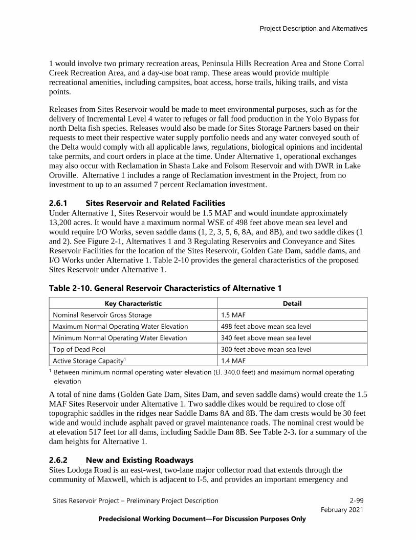
Project Description and Alternatives
Sites Reservoir Project – Preliminary Project Description 2-99February 2021
Predecisional Working Document—For Discussion Purposes Only
1 would involve two primary recreation areas, Peninsula Hills Recreation Area and Stone Corral Creek Recreation Area, and a day-use boat ramp. These areas would provide multiple recreational amenities, including campsites, boat access, horse trails, hiking trails, and vista points.
Releases from Sites Reservoir would be made to meet environmental purposes, such as for the delivery of Incremental Level 4 water to refuges or fall food production in the Yolo Bypass for north Delta fish species. Releases would also be made for Sites Storage Partners based on their requests to meet their respective water supply portfolio needs and any water conveyed south of the Delta would comply with all applicable laws, regulations, biological opinions and incidental take permits, and court orders in place at the time. Under Alternative 1, operational exchanges may also occur with Reclamation in Shasta Lake and Folsom Reservoir and with DWR in Lake Oroville. Alternative 1 includes a range of Reclamation investment in the Project, from no investment to up to an assumed 7 percent Reclamation investment.
2.6.1 Sites Reservoir and Related Facilities Under Alternative 1, Sites Reservoir would be 1.5 MAF and would inundate approximately 13,200 acres. It would have a maximum normal WSE of 498 feet above mean sea level and would require I/O Works, seven saddle dams (1, 2, 3, 5, 6, 8A, and 8B), and two saddle dikes (1 and 2). See Figure 2-1, Alternatives 1 and 3 Regulating Reservoirs and Conveyance and Sites Reservoir Facilities for the location of the Sites Reservoir, Golden Gate Dam, saddle dams, and I/O Works under Alternative 1. Table 2-10 provides the general characteristics of the proposed Sites Reservoir under Alternative 1.
Table 2-10. General Reservoir Characteristics of Alternative 1
Key Characteristic Detail Nominal Reservoir Gross Storage 1.5 MAF Maximum Normal Operating Water Elevation 498 feet above mean sea level Minimum Normal Operating Water Elevation 340 feet above mean sea level Top of Dead Pool 300 feet above mean sea level Active Storage Capacity1 1.4 MAF
1 Between minimum normal operating water elevation (El. 340.0 feet) and maximum normal operating elevation
A total of nine dams (Golden Gate Dam, Sites Dam, and seven saddle dams) would create the 1.5 MAF Sites Reservoir under Alternative 1. Two saddle dikes would be required to close off topographic saddles in the ridges near Saddle Dams 8A and 8B. The dam crests would be 30 feet wide and would include asphalt paved or gravel maintenance roads. The nominal crest would be at elevation 517 feet for all dams, including Saddle Dam 8B. See Table 2-3. for a summary of the dam heights for Alternative 1.
2.6.2 New and Existing Roadways Sites Lodoga Road is an east-west, two-lane major collector road that extends through the community of Maxwell, which is adjacent to I-5, and provides an important emergency and
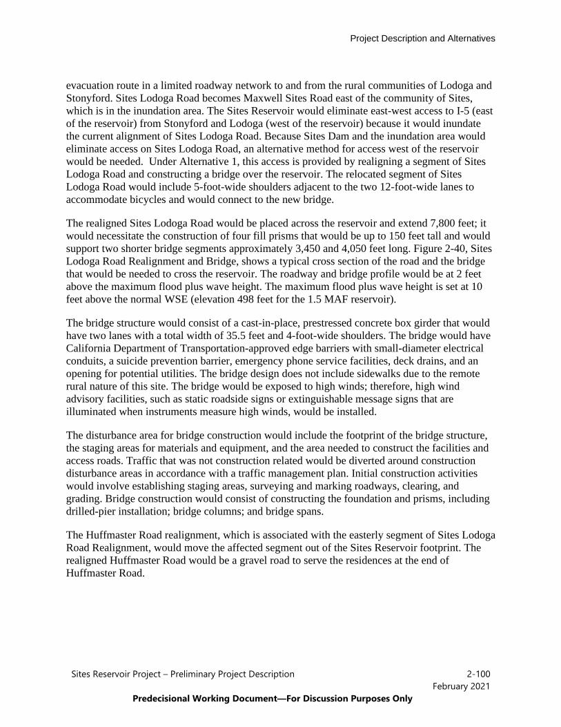
Project Description and Alternatives
Sites Reservoir Project – Preliminary Project Description 2-100February 2021
Predecisional Working Document—For Discussion Purposes Only
evacuation route in a limited roadway network to and from the rural communities of Lodoga and Stonyford. Sites Lodoga Road becomes Maxwell Sites Road east of the community of Sites, which is in the inundation area. The Sites Reservoir would eliminate east-west access to I-5 (east of the reservoir) from Stonyford and Lodoga (west of the reservoir) because it would inundate the current alignment of Sites Lodoga Road. Because Sites Dam and the inundation area would eliminate access on Sites Lodoga Road, an alternative method for access west of the reservoir would be needed. Under Alternative 1, this access is provided by realigning a segment of Sites Lodoga Road and constructing a bridge over the reservoir. The relocated segment of Sites Lodoga Road would include 5-foot-wide shoulders adjacent to the two 12-foot-wide lanes to accommodate bicycles and would connect to the new bridge.
The realigned Sites Lodoga Road would be placed across the reservoir and extend 7,800 feet; it would necessitate the construction of four fill prisms that would be up to 150 feet tall and would support two shorter bridge segments approximately 3,450 and 4,050 feet long. Figure 2-40, Sites Lodoga Road Realignment and Bridge, shows a typical cross section of the road and the bridge that would be needed to cross the reservoir. The roadway and bridge profile would be at 2 feet above the maximum flood plus wave height. The maximum flood plus wave height is set at 10 feet above the normal WSE (elevation 498 feet for the 1.5 MAF reservoir).
The bridge structure would consist of a cast-in-place, prestressed concrete box girder that would have two lanes with a total width of 35.5 feet and 4-foot-wide shoulders. The bridge would have California Department of Transportation-approved edge barriers with small-diameter electrical conduits, a suicide prevention barrier, emergency phone service facilities, deck drains, and an opening for potential utilities. The bridge design does not include sidewalks due to the remote rural nature of this site. The bridge would be exposed to high winds; therefore, high wind advisory facilities, such as static roadside signs or extinguishable message signs that are illuminated when instruments measure high winds, would be installed.
The disturbance area for bridge construction would include the footprint of the bridge structure, the staging areas for materials and equipment, and the area needed to construct the facilities and access roads. Traffic that was not construction related would be diverted around construction disturbance areas in accordance with a traffic management plan. Initial construction activities would involve establishing staging areas, surveying and marking roadways, clearing, and grading. Bridge construction would consist of constructing the foundation and prisms, including drilled-pier installation; bridge columns; and bridge spans.
The Huffmaster Road realignment, which is associated with the easterly segment of Sites Lodoga Road Realignment, would move the affected segment out of the Sites Reservoir footprint. The realigned Huffmaster Road would be a gravel road to serve the residences at the end of Huffmaster Road.
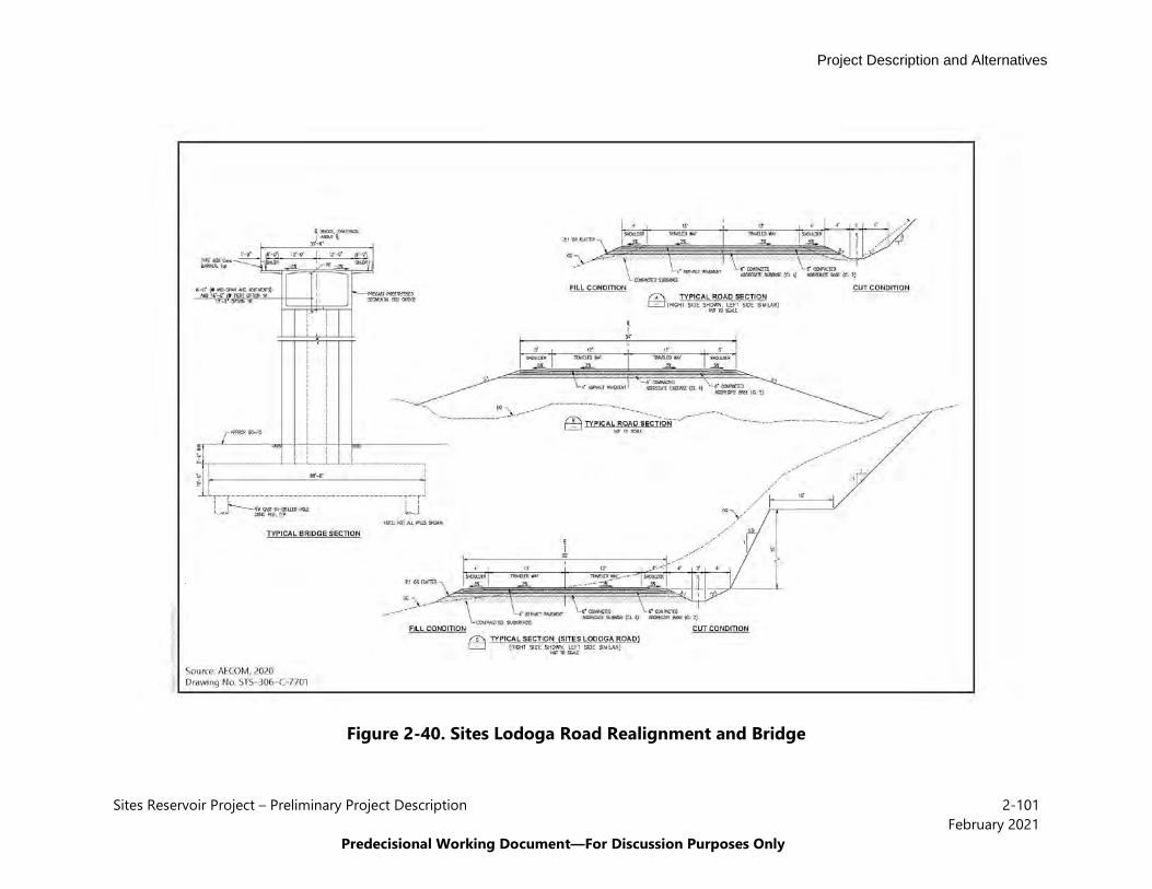
Project Description and Alternatives
Sites Reservoir Project – Preliminary Project Description 2-101February 2021
Predecisional Working Document—For Discussion Purposes Only
Figure 2-40. Sites Lodoga Road Realignment and Bridge

Project Description and Alternatives
Sites Reservoir Project – Preliminary Project Description 2-102February 2021
Predecisional Working Document—For Discussion Purposes Only
2.6.3 Operations and Maintenance In addition to the operations and maintenance activities common to all Action Alternatives, operations and maintenance activities under Alternative 1 would include Reclamation as a Storage Partner in the Project and maintenance of the bridge as described below.
Water Operations Alternative 1 includes a range of potential investment in the Project by Reclamation. For the purposes of modeling, two options have been identified under this alternative – Alternative 1A includes no Reclamation investment and Alternative 1B includes up to 7 percent Reclamation investment, which equates to about 91,000 AF of storage allocation dedicated to Reclamation in Sites Reservoir. With investment from Reclamation, 7 percent of Sites Reservoir storage would be managed as a CVP supply under Alternative 1. Reclamation’s share of Sites water would be flexibly used by Reclamation to meet CVP objectives providing water for water supply and environmental needs. Increased storage, diversion, and release capacity provides the CVP with additional opportunities to store and release water when it may have been otherwise constrained. Releases for Reclamation would generally be made for a variety of purposes as identified and directed by Reclamation and would be made in the same manner as described for all Storage Partners.
Bridge Maintenance There are no day-to-day operations of the bridge (no moving components of the bridge that would be operated on a daily basis). Typical bridge maintenance activities would include replacing damaged or missing signage, replacing or repairing railings, replacing or repairing damage to the bridge deck (road surface), sealing joints, repairing erosion on approaches, unplugging drains and removing debris, and checking for and repairing faulty electrical contacts. The bridge would be periodically inspected through walking through inspection to detect any obvious defects, hazards or potential problems and to also monitor known problems. The bridge would also be periodically inspected by Caltrans to detect any major structural concerns. Repairs and replacements would be made as needed based on these inspections.
2.7 Alternative 2 Specific Elements
The unique features of Alternative 2 include the following:
• Reservoir capacity would be 1.3 MAF;• A local access road around the southern end of the reservoir would provide access to the
west of the Project; and• Dunnigan Pipeline would extend to and discharge at the Sacramento River with a partial
discharge at the CBD.
See Figure 2-1 and Figure 2-2 for a plan view of the Alternative 2 features.
Alternative 2 would impound surface water at the Golden Gate Dam on Funks Creek, Sites Dam on Stone Corral Creek, and a series of four saddle dams along the eastern and northern rims of

Project Description and Alternatives
Sites Reservoir Project – Preliminary Project Description 2-103February 2021
Predecisional Working Document—For Discussion Purposes Only
reservoir would close off topographic saddles in the surrounding ridges to form Sites Reservoir. The 1.3-MAF reservoir would inundate approximately 12,600 acres and require four saddle dams and three saddle dikes. Alternative 2 would convey water from the Sacramento River through existing or upgraded TC Canal and GCID Main Canal facilities to new and upgraded regulating reservoirs and into the new Sites Reservoir. Existing and new facilities would convey water from Sites Reservoir for uses along the TC Canal, along the GCID Main Canal and down the TC Canal to the new Dunnigan Pipeline and to the Sacramento River for direct release to the river. Alternative 2 also includes a partial release into the CBD, and flows would enter the Yolo Bypass or Sacramento River. Construction roads, local roads, and maintenance roads would be developed or realigned to accommodate the reservoir facilities, including the realignment of Sites Lodoga Road with a new local access road around the southern end of the reservoir. Alternative 1 would involve two primary recreation areas, Peninsula Hills Recreation Area and Stone Corral Creek Recreation Area, and a day-use boat ramp. These areas would provide multiple recreational amenities, including campsites, boat access, horse trails, hiking trails, and vista points.
Releases from Sites Reservoir would be made to meet environmental purposes, such as for the delivery of Incremental Level 4 water to refuges or fall food production in the Yolo Bypass for north Delta fish species. Releases would also be made for Sites Storage Partners based on their requests to meet their respective water supply portfolio needs, and any water conveyed south of the Delta would comply with all applicable laws, regulations, biological opinions and incidental take permits, and court orders in place at the time. Under Alternative 2, operational exchanges may also occur with Reclamation in Shasta Lake and Folsom Reservoir and with DWR in Lake Oroville. Alternative 2 does not include Reclamation investment in the Project.
2.7.1 Sites Reservoir and Related Facilities Under Alternative 2, Sites Reservoir would be 1.3 MAF and would inundate approximately 12,600 acres (600 acres less than Alternative 1). It would have a maximum normal WSE of 482 feet above mean sea level (17 feet lower than Alternative 1) and would require I/O Works, four saddle dams (3, 5, 8A, and 8B) and three saddle dikes (1, 2, and 3). Figure 2-3 shows the location of Sites Dam and Golden Gate Dam and the location of the four saddle dams and three saddle dikes under Alternative 2. Under Alternative 2, Saddle Dams 3 and 5 would not have emergency release systems into the Hunters Creek watershed. Figure 2-11 provides the general characteristics of the proposed Sites Reservoir under Alternative 2.
Table 2-11. General Reservoir Characteristics of Alternative 2
Key Characteristic Detail Nominal Reservoir Gross Storage 1.3 MAF Maximum Normal Operating Water Elevation 482 feet above mean sea level Minimum Normal Operating Water Elevation 340 feet above mean sea level Top of Dead Pool 300 feet above mean sea level Active Storage Capacity1 1.2 MAF
1 Between minimum normal operating water elevation (El. 340.0 feet) and maximum normal operating elevation
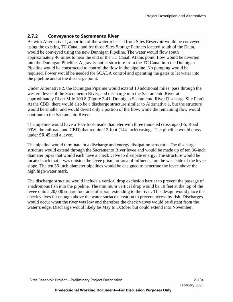
Project Description and Alternatives
Sites Reservoir Project – Preliminary Project Description 2-104February 2021
Predecisional Working Document—For Discussion Purposes Only
2.7.2 Conveyance to Sacramento River As with Alternative 1, a portion of the water released from Sites Reservoir would be conveyed using the existing TC Canal, and for those Sites Storage Partners located south of the Delta, would be conveyed using the new Dunnigan Pipeline. The water would flow south approximately 40 miles to near the end of the TC Canal. At this point, flow would be diverted into the Dunnigan Pipeline. A gravity outlet structure from the TC Canal into the Dunnigan Pipeline would be constructed to control the flow in the pipeline. No pumping would be required. Power would be needed for SCADA control and operating the gates to let water into the pipeline and at the discharge point.
Under Alternative 2, the Dunnigan Pipeline would extend 10 additional miles, pass through the western levee of the Sacramento River, and discharge into the Sacramento River at approximately River Mile 100.8 (Figure 2-41, Dunnigan Sacramento River Discharge Site Plan). At the CBD, there would also be a discharge structure similar to Alternative 1, but the structure would be smaller and would divert only a portion of the flow, while the remaining flow would continue to the Sacramento River.
The pipeline would have a 10.5-foot-inside diameter with three tunneled crossings (I-5, Road 99W, the railroad, and CBD) that require 12-foot (144-inch) casings. The pipeline would cross under SR 45 and a levee.
The pipeline would terminate in a discharge and energy dissipation structure. The discharge structure would extend through the Sacramento River levee and would be made up of ten 36-inch diameter pipes that would each have a check valve to dissipate energy. The structure would be located such that it was outside the levee prism, or area of influence, on the west side of the levee slope. The ten 36-inch diameter pipelines would be designed to penetrate the levee above the high high-water mark.
The discharge structure would include a vertical drop exclusion barrier to prevent the passage of anadromous fish into the pipeline. The minimum vertical drop would be 10 feet at the top of the levee onto a 20,000 square foot area of riprap extending to the river. This design would place the check valves far enough above the water surface elevation to prevent access by fish. Discharges would occur when the river was low and therefore the check valves would be distant from the water’s edge. Discharge would likely be May to October but could extend into November.
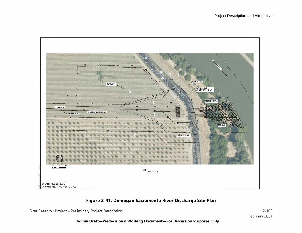
Project Description and Alternatives
Sites Reservoir Project – Preliminary Project Description 2-105February 2021
Admin Draft—Predecisional Working Document—For Discussion Purposes Only
Figure 2-41. Dunnigan Sacramento River Discharge Site Plan
Project Description and Alternatives
Sites Reservoir Project – Preliminary Project Description 2-106February 2021
Predecisional Working Document—For Discussion Purposes Only
Construction would not occur in the winter unless it was a critically dry year. A non-winter construction window would be targeted because even small amounts of rain cause the roads to become slick, which would slow and/or prevent the movement of construction equipment. The construction window would exclude mid-October through March 31. Because groundwater is 3 feet below ground surface, the contractor would install dewatering wells every 50 to 100 feet. However, excavating and placing pipes closely, spatially and temporarily, would avoid running the dewatering system for long periods. Construction of the Dunnigan Pipeline would require crossing nearly 20 irrigation laterals and drainage canals. Bypass pipes would be used to allow irrigation water to flow down canals and also allow drainage water from irrigation to flow. Boring may be required under SR 45, if open cut is not possible. A boring will be required under the levees adjacent to the CBD and under the CBD.
The discharge structure would be located on the west bank of the river about 1 mile upstream of the Rough and Ready Pumping Plant. As described in Appendix 2D, Best Management Practices, in-water construction activities in the Sacramento River would occur during the work window of September 1 through October 15. This work would include constructing a coffer dam. Once the coffer dam is completed, work would continue in the dry and could occur outside the in-water work window. Pile driving or a vibration hammer would be used to install piles on the land side of the levee.
2.7.3 New and Existing Roadways Realignment of Huffmaster Road and construction of the new South Road would occur under Alternative 2 (Figure 2-35). As with Alternative 1, Sites Dam and the inundation area would inundate 4.2 miles of the Sites Lodoga Road and eliminate access on this 13-mile-long collector road. Similar to Alternative 1, the relocated segment of Sites Lodoga Road would include 5-foot-wide shoulders adjacent to the two 12-foot-wide lanes to accommodate bicycles and would provide access to the Stone Corral Recreation Area. Similar to Alternative 1, Huffmaster Road would be realigned for approximately 9 miles. A new South Road would be constructed and connect to the end of the realigned portion of Huffmaster Road. It would be approximately 20 miles. The total length of the realigned portion of Huffmaster Road and the new South Road would be approximately 30 miles, all of which would be paved.
All other permanent access, maintenance, detour and construction roads would be the same for the reservoir facilities between Alternatives 1 and 2. These roads would be needed regardless of the inundation area size to serve the planned facilities and recreation areas.
The South Road would generally require more excavation and more aggregate when compared to the bridge under Alternative 1. These materials are listed in Appendix 2C, Construction Methods, Means, and Assumptions, Table Alt 2, Preliminary Quantities for Roads.
2.7.4 Operations and Maintenance Operations and maintenance activities under Alternative 2 would be the same as those described for all Action Alternatives above. In addition to the water operations activities described above that are common to all Action Alternatives, Alternative 2 includes releases directly to the Sacramento River from the extended Dunnigan Pipeline, with a partial release into the CBD.
Project Description and Alternatives
Sites Reservoir Project – Preliminary Project Description 2-107February 2021
Predecisional Working Document—For Discussion Purposes Only
2.8 Alternative 3 Specific Elements
Alternative 3 facilities and project components would be the same as Alternative 1, as described above. Operationally, Alternative 3 would include increased Reclamation participation and investment, with investment of up to 25 percent of the Project cost.
Under Alternative 3, Reclamation would have an increased investment in Sites Reservoir of up to 25 percent as compared to up to 7 percent in Alternative 1. The increased level of Reclamation investment would result in up to 25 percent of Sites Reservoir storage space being dedicated to Reclamation’s use. Reclamation’s share of Sites water would be flexibly used by Reclamation to meet CVP objectives providing water for water supply and environmental needs. The increased level of Reclamation investment would also result in increased opportunities for maintaining cold water pool in Shasta Lake, Folsom Lake and Lake Oroville through Reclamation operating its up to 25 percent investment as part of the integration of the CVP.
Increased Reclamation investment in the Project would require some reduction in local participation for Alternative 3 as compared with Alternative 1. Alternative 3 assumes that Sites Storage Partners that are local agencies would reduce their participation in the Project to accommodate the investment by Reclamation. The State’s Proposition 1 investment for ecosystem, flood control and recreation benefits does not change with the increased Reclamation investment in Alternative 3.
All other components of Alternative 3 are the same as those for Alternative 1.
Project Description and Alternatives
Sites Reservoir Project – Preliminary Project Description 2-108February 2021
Predecisional Working Document—For Discussion Purposes Only
2.9 References Cited
Bureau of Reclamation. 2020. Final Feasibility Report. North-of-the-Delta Offstream Storage Investigation. December.
Bureau of Reclamation and California Department of Water Resources. 2006. North-of-the-Delta Offstream Storage Investigation: Initial Alternatives Information Report. May
California Department of Fish and Wildlife. 2020. Incidental Take Permit for Long-term Operations of the State Water Project in the Sacramento-San Joaquin Delta (2081-20129-066-00). March.
California Water Commission. Undated. Water Storage Investment Program – Commission Determinations and Additional Eligibility Requirement, Sites Reservoir Project.
Cavallo, B., P. Gaskill, J. Melgo, and S. C. Zeug. 2015. Predicting juvenile Chinook salmon routing in riverine and tidal channels of a freshwater estuary. Environmental Biology of Fishes 98:1571-1582.
del Rosario, R. B., Y. J. Redler, K. Newman, P. L. Brandes, T. Sommer, K. Reece, and R. Vincik. 2013. Migration Patterns of Juvenile Winter-Run-Sized Chinook Salmon (Oncorhynchus tshawytscha) through the Sacramento–San Joaquin Delta. San Francisco Estuary and Watershed Science 11(1):1-22.
Hassrick, J.L., Ammann, A.J., Perry, R.W., John, S.N., and Daniels, M.E. In Prep. Spatiotemporal variation in survival of endangered winter run Chinook Salmon outmigrating from the Sacramento River.
Henderson, M. J., I. S. Iglesias, C. J. Michel, A. J. Ammann, and D. D. Huff. 2019. Estimating spatial–temporal differences in Chinook salmon outmigration survival with habitat- and predation-related covariates. Canadian Journal of Fisheries and Aquatic Sciences 76:1549-1561.
Iglesias, I. S., M. J. Henderson, C. J. Michel, A. A. J., and D. D. Huff. 2017. Chinook salmon smolt mortality zones and the influence of environmental factors on out-migration success in the Sacramento River Basin. Pages 30 in National Marine Fisheries Service. Prepared for: U.S. Fish and Wildlife Service Pacific Southwest Region Central Valley Project Improvement Act Sacramento, CA. Agreement Number F15PG00146. 30 p.
Michel, Cyril J., Jeremy J. Notch, Flora Cordoleani, and Eric M. Danner. In Press. Ecological nonlinearities inform the design of functional flows for imperiled fish in a highly modified river.
Michel, C. J., A. J. Ammann, S. T. Lindley, P. T. Sandstrom, E. D. Chapman, M. J. Thomas, G. P. Singer, A. P. Klimley, and R. B. MacFarlane. 2015. Chinook salmon outmigration
Project Description and Alternatives
Sites Reservoir Project – Preliminary Project Description 2-109February 2021
Predecisional Working Document—For Discussion Purposes Only
survival in wet and dry years in California’s Sacramento River. Canadian Journal of Fisheries and Aquatic Sciences 72(11):1749-1759.
Michel, C. J. 2010. River and Estuarine Survival and Migration of yearling Sacramento Chinook Salmon (Oncorhynchus tshawytscha) smolts and the influence of environment. University of California, Santa Cruz. Santa Cruz, California.
National Marine Fishery Service. 2019. Biological Opinion on Long-term Operations of the CVP and SWP. October.
Notch, J. 2017. Out-Migration Survival of Wild Chinook Salmon (Oncorhynchus tshawytscha) Smolts from Mill Creek through the Sacramento River during Drought Conditions. Master's Thesis. University of California, Santa Cruz.
Poytress, W. R., J. J. Gruber, F. D. Carrillo, and S. D. Voss. 2014. Compendium Report of Red Bluff Diversion Dam Rotary Trap Juvenile Anadromous Fish Production Indices for Years 2002–2012. U.S. Fish and Wildlife Service. Red Bluff Fish and Wildlife Office, CA. 151 pp.
Sites Project Authority. 2020. Sites Project Value Planning Alternatives Appraisal Report. April.
State Water Resources Control Board. 2000. Revised Water Right Decision 1641. March.
U.S. Fish and Wildlife Service. 2019. Biological Opinion for the Reinitiation of Consultation on the Coordinated Operations of the CVP and SWP. Service File No. 08FBTD00-2019-F-0164. October.