Embed Size (px)
Citation preview

CI/SfB(23) Eq4
Part 2 September2008
The Original Voided Flat Slabswith BubbleDeck
B u b b l e D e c kS t r u c t u r e S o l u t i o n s
Site Erection &Installation Manual
Type A - Filigree Elements
U N I T E D K I N G D O M
R

S i t e
Pre-Construction Planning
We believe the key to achieving a successful construction build is
meticulous preparation and planning, with good communication. Well in
advance of construction commencing on site BubbleDeck’s managerial
and technical team will closely work with you - advising on and defining
a detailed programme for the timing and phasing of drawing
preparation, drawing review, drawing sign-off approval, element
manufacture and element delivery to site – to match your strategic
approach and reflect your overall construction programme.
Please take into account there is a lead in period from the date of
placing your BubbleDeck order – typically 3 weeks for our design /
general arrangement drawing work plus 9 weeks for preparation,
producing production / installation drawings and manufacturing of the
elements (on larger projects drawing and manufacturing will be
undertaken in phases to match your construction programme) – before
we can commence site deliveries. Between these periods you need to
allow sufficient time for submitting our design / general arrangement
drawings to your Approved Inspector and receiving Building control
approval, although in special circumstances and smaller projects we can
reduce these periods if our other commitments allow.
The pre-construction planning stages comprises:-1. Issuing to us frozen ‘For Construction’ Architects / Engineers general
arrangement plans, sections and relevant details in ,dwg file format
together with final loading information and firm order / deposit
payment.
2. Preparation by us of BubbleDeck full engineering design and general
arrangement plans, showing element layout, and submission to you
for review and technical approval.
3. Submission by you of our design / drawings to Approved Inspector.
Referral to us of any queries and us providing answers / further
information as may be required.
4. Confirmation from you Building Control approval receipt and issuing
to us sign-off approval of BubbleDeck design / general arrangement
drawings.
5. Develop together programme for production / installation drawings,
manufacturing and delivery to site
6. Preparation by us of a detailed programme for production /
installation drawings, manufacturing and delivery to site. Review by
you and issuing to us programme approval.
Erection and Installation ManualType A – Filigree Elements
BubbleDeck is a structural voided flat slab system that reduces
dead weight of a floor slab by 33%, allowing longer spans
between column supports and a whole range of other design,
cost and construction benefits. The system eliminates secondary
supporting structure such as beams – the completed floor slab
spans in two directions directly onto pre-cast / in-situ reinforced
concrete columns or structural walls.
BubbleDeck is usually manufactured as partly pre-cast filigree
elements, combining the benefits gained from off-site MMC
techniques of factory manufacture in controlled conditions,
ensuring quality control and consistency, with on-site completion
of the final concrete pour, resulting in a seamless completed floor
slab - without the issues associated with fully pre-cast methods
arising from dry joints resulting in noise transfer needing
additional work to seal gaps, and need for structural toppings
with additional construction layers. When the site topping
concrete has been cast a BubbleDeck structure is complete –
providing integral overall building stability, fire resistance,
weatherproofing, and sound insulation.
Site erection and installation is simple and fast, well within the
capabilities of any competent concrete contractor or sub-
contractor. On previous projects over 800m2 of BubbleDeck has
been erected and completed within 4 working days. The elements
are manufactured 3 metres wide (upon request prior to ordering
2.4 metres wide where site access is restricted) and the length is
varied, to suit project floor-plate configuration and transport
efficiency, up to a maximum of 10 metres long.
For more background information about the BubbleDeck system
please study our separate Product Introduction Brochure prior to
reading further.
Planning Pre-Cast Element Erection
Prior to us commencing preparation production / installation drawings (see Stage 7, left) you
must confirm to us your planned sequence of erecting the BubbleDeck elements on site during
construction. This sequence has to be incorporated on our drawing element numbering at an
early stage and passed to our factory in order to ensure a) the correct element edge profiles
are manufactured, and b) plan the sequence of manufacturing / transporting elements.
a) Element Edge Profiles: Longitudinal edges of elements require different detailing dependant
upon their position – see drawing below showing slab edge cross-sections element as planned.
It is important the large splay shown on the right hand longitudinal edge is present at every
junction between two elements to provide adequate concrete cover, for fire resistance and
durability performance, to the loose reinforcement splice bars laid across the elements joints on
top of the pre-cast concrete layer.
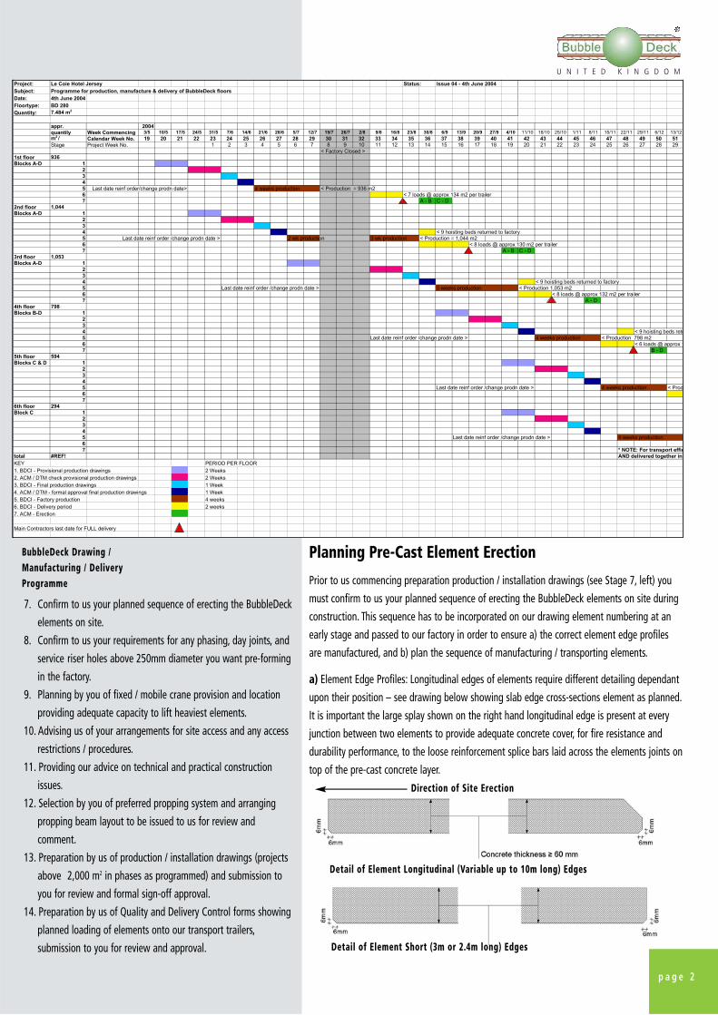
BubbleDeck Drawing /Manufacturing / DeliveryProgramme
Project: Le Coie Hotel Jersey Status: Issue 04 - 4th June 2004
Subject: Programme for production, manufacture & delivery of BubbleDeck floors
Date: 4th June 2004
Floortype: BD 280
Quantity: 7.484 m2
appr. 2004
quantily Week Commencing 3/5 10/5 17/5 24/5 31/5 7/6 14/6 21/6 28/6 5/7 12/7 19/7 26/7 2/8 9/8 16/8 23/8 30/8 6/9 13/9 20/9 27/9 4/10 11/10 18/10 25/10 1/11 8/11 15/11 22/11 29/11 6/12 13/12
m2 / Calendar Week No. 19 20 21 22 23 24 25 26 27 28 29 30 31 32 33 34 35 36 37 38 39 40 41 42 43 44 45 46 47 48 49 50 51
Stage Project Week No. 1 2 3 4 5 6 7 8 9 10 11 12 13 14 15 16 17 18 19 20 21 22 23 24 25 26 27 28 29
< Factory Closed >
1st floor 936
Blocks A-D 1
2
3
4
5 Last date reinf order/change prodn date> 4 weeks production < Production = 936 m2
6 < 7 loads @ approx 134 m2 per trailer
7 A - B C - D
2nd floor 1,044
Blocks A-D 1
2
3
4 < 9 hoisting beds returned to factory
5 Last date reinf order /change prodn date > 2 wk production 3 wk production < Production = 1,044 m2
6 < 8 loads @ approx 130 m2 per trailer
7 A - B C - D
3rd floor 1,053
Blocks A-D 1
2
3
4 < 9 hoisting beds returned to factory
5 Last date reinf order /change prodn date > < Production 1,053 m2
6 < 8 loads @ approx 132 m2 per trailer
7 A - D
4th floor 798
Blocks B-D 1
2
3
4 < 9 hoisting beds retu
5 Last date reinf order /change prodn date > 4 weeks production < Production 798 m2
6 < 6 loads @ approx 1
7 B - D
5th floor 594
Blocks C & D 1
2
3
4
5 Last date reinf order /change prodn date > 4 weeks production < Prod
6
7
6th floor 294
Block C 1
2
3
4
5 Last date reinf order /change prodn date > 4 weeks production
6
7 * NOTE: For transport effic
total #REF! AND delivered together in
KEY PERIOD PER FLOOR
1. BDCI - Provisional production drawings 2 Weeks
2. ACM / DTM check provisional production drawings 2 Weeks
3. BDCI - Final production drawings 1 Week
4. ACM / DTM - formal approval final production drawings 1 Week
5. BDCI - Factory production 4 weeks
6. BDCI - Delivery period 2 weeks
7. ACM - Erection
Main Contractors last date for FULL delivery
5 weeks production
7. Confirm to us your planned sequence of erecting the BubbleDeck
elements on site.
8. Confirm to us your requirements for any phasing, day joints, and
service riser holes above 250mm diameter you want pre-forming
in the factory.
9. Planning by you of fixed / mobile crane provision and location
providing adequate capacity to lift heaviest elements.
10. Advising us of your arrangements for site access and any access
restrictions / procedures.
11. Providing our advice on technical and practical construction
issues.
12. Selection by you of preferred propping system and arranging
propping beam layout to be issued to us for review and
comment.
13. Preparation by us of production / installation drawings (projects
above 2,000 m2 in phases as programmed) and submission to
you for review and formal sign-off approval.
14. Preparation by us of Quality and Delivery Control forms showing
planned loading of elements onto our transport trailers,
submission to you for review and approval.
Direction of Site Erection
Detail of Element Longitudinal (Variable up to 10m long) Edges
Detail of Element Short (3m or 2.4m long) Edges
p a g e 2
U N I T E D K I N G D O M
R

b) Manufacturing and Transporting Sequence: We
will programme the order of manufacturing
elements and loading of the elements onto our
transport to reflect, as closely as practically
feasible, your planned erection sequence. However,
for transport efficiency and safety, some elements
have to be loaded on the transport trailers out of
sequence to their erection order (e.g. small
elements have to be stacked on top of larger
elements), in which case these elements can be
temporarily lifted off and stored elsewhere on site
while the transport trailer is unloaded. The order of
loading elements onto the transport trailers will be
shown on our Quality and Delivery Control form.
Formal drawing review & sign offprior to manufacture
Once you have reviewed and we have received
your sign-off of our production / installation
drawings we can then implement manufacture of
materials and the elements and be ready to
commence site deliveries of prefabricated
BubbleDeck elements within advised
manufacturing lead-in period.
We appreciate progress of construction on site can
be affected by many external factors including
exceptionally adverse weather and other events
beyond your control. If you need to change the
programming of BubbleDeck deliveries and/or
manufacture in response to such events please
immediately inform us so we can then re-
programme to your requirements. Once
BubbleDeck trailers have left our factory we regret
we are unable to defer site delivery without
passing on additional transport and storage /
trailer hire costs. We have even advanced deliveries
to keep up with quicker than expected progress
constructing BubbleDeck slabs on site.
As part of our comprehensive service we will supply you with the following
construction information, advice, products and assistance:-
Planning Pre-Cast Element Erection continued
Service / Product
Engineering Design of BubbleDeck floor slabs & drawings. Submittingdesign to you for review and sign-off. Liaison with you about any checkingengineer / Approved Inspector queries and providing further informationas required.
Preparation of manufacturing and construction drawings comprising i)Element layout plan, ii) Loose bottom reinforcement (site installation), iii)Loose top reinforcement (site installation), iv) Bubble pattern v) Pre-castreinforcement (incorporated into elements at factory). Submittingdrawings to you & Consultants for review and sign-off.
Preparing programme for manufacture and supply of products to site,agreeing with you and placing orders for materials and manufacturing.Preparation of bar bending schedules of loose site reinforcement forsupply to site by others.Providing site operatives with product induction seminar.
Providing our advice on technical and practical construction issues.BubbleDeck Site Erection and Installation Manual.BubbleDeck Health & Safety Policy Guidance.Quality and Delivery Control Forms.
Manufacture of prefabricated BubbleDeck elements comprising top &bottom mesh reinforcement / girders joining top / bottom mesh together /additional bar reinforcement / plastic bubble void formers (Type A Filigreeelements with 70mm pre-cast concrete layer encasing bottom meshreinforcement).
Preparing loose site reinforcement bar bending schedules for supply tosite by others.
Monitoring and arranging delivery of prefabricated BubbleDeckelements to site, on time, using between 8 metre to 13.6 metre longflatbed trailers.Loan of BubbleDeck lifting chainsets during site installation for lifting andplacing BubbleDeck elements.
Technical advice and guidance to yourselves and site operatives on siteinstallation & construction works.
Site inspections of BubbleDeck installation & loose reinforcement checkingprior to casting of in-situ concrete.
Following completion of works on site and account settlement enteringinto suitable Collateral Warranty/s (subject to wording acceptable to ourInsurers) as may be required and provision of our Professional Indemnity& Product Liability Insurance cover.
Project Stage
BubbleDeck Design
BubbleDeck DrawingProduction
Construction Planning
Product Advice and Support
Manufacturing Product
Loose Reinforcement
Site Delivery
Site Support
Site Inspections
Insurance / Guarantees
BubbleDeck’s Construction PackageOur Services and Products
p a g e 3
Our designservice includesfull engineeringcalculations andsite installation
drawings.

Combined Column / Wall & BubbleDeck Construction Method
While sequencing of site operations is your responsibility to decide we recommend the most efficient method, saving valuable site time
and overheads, is to plan construction of supporting r.c. columns and walls together with the BubbleDeck floor slab in one combined
erection operation as detailed in the following table:-
Activities
a) Fabricate & erect r.c. column & wall reinforcement. b) Fabricate formwork shuttering with horizontal plywood top flange200mm wide extending out from vertical shuttering & bracket supportedby vertical shuttering.
a) Erect Temporary Propping beams. (Refer to Stage 1 on page 5)b) Erect formwork shuttering and (when suitable stable propping such asSGB GASS system is used) brace upper formwork off temporary proppingframes.
Note: When column / wall formwork is to be braced off slab it will bemore convenient to erect this before erecting temporary propping)
Receive, lift and place BubbleDeck elements onto temporary proppingbeams. (Refer to Stage 2 on page 6)
Install BubbleDeck loose reinforcement (Refer to Stage 3 on page 8)
Fabricate and erect perimeter & tolerance joint shuttering (Refer to Stage4 on page 9)
Prepare columns, walls and BubbleDeck slab for concreting (Refer to Stage5 on page 9)
Notify us of the date set for concreting (Refer to Stage 6 on page 10)
Pour concrete firstly into columns and walls, vibrate and compact. Then asa continuous process pour concrete onto BubbleDeck slabs (Refer to Stage7 on page 10)
Stage Operation
1 Column / wall reinforcement & formwork(Prior to BubbleDeck element delivery)
2 Temporary Propping(Prior to BubbleDeck element delivery)
3 BubbleDeck Element Erection
4 Loose Reinforcement
5 Slab shuttering
6 Slab Preparation
7 BubbleDeck Site Inspection
8 Pouring Site Concrete
Concrete Column / WallConstruction
Important: In accordance with good practice and British Standards DONOT overpour r.c. columns / walls in order to avoid reducing the slabseffective depth at support locations. Only use enough concrete tobring r.c. columns / walls up to the underside of the BubbleDeck flatslab level. In the event r.c. columns / walls are concreted above thislevel our Site Advisor/Inspector may require the concrete to be cutdown around the perimeter of r.c. columns / walls to ensure adequateconnection with the BubbleDeck slabs.
This combined erection method has the advantages of a) Condensing a two stage sequence (erecting & castingcolumns / walls first and then BubbleDeck slabs second) into a one stage sequence; b) Providing s stable & firmplatform for casting columns / walls; c) Eliminating separate concrete deliveries for columns / walls and slabs;and d) ensuring a good bond between column / wall and BubbleDeck slab site concrete.
p a g e 4
U N I T E D K I N G D O M
R

Back-Propping
When consecutive floor slabs within one block are
to be constructed above each other either:- a) the
slab below the one being constructed must be
back-propped, or alternatively b) each completed
slab must be self-supporting within the maximum
allowed deflection.
Option a) Prior to erecting propping for the next,
subsequent, slab above the completed slab
remove the propping from below the completed
slab and erect back-props at 2.4m intervals
(without parallel beams) at either mid-span or
third-span, dependant upon length of spans
involved.
Option b) Prior to erecting propping for the next,
subsequent, slab above loosen the props below
the completed slab, to allow the floor to reach it’s
maximum deflection, and then tighten the props
again. This is to ensure additional loads from the
slab being erected above are taken on its own
props rather than adding to loads onto the floor
directly below, avoiding weight accumulation from
consecutive floors placing unnecessary strain on
props and other construction elements.
Typical cross-section of temporary propping system
Site Erection and InstallationType A – Filigree Elements
p a g e 5
Stage 1 – Erect Temporary ProppingDuring erection each slab must be placed on suitable temporary
propping beams arranged in parallel rows mounted on props
sufficient to adequately support the weight of the pre-cast filigree
elements plus the loose reinforcement fixed on site, concrete
poured on site and all other site construction loads applied during
final pouring of the concrete topping and curing of the slab.
• The maximum distance between propping beams must not be
greater than 1.8 metres or as advised
• The maximum distance of the propping beams from slab edges
must be as follows:
- from an edge where a slab is supported on brick or
concrete walls – 300mm
- from an edge next to construction tolerance joints –
200mm
Propping beams must be at right angles to the direction of the
reinforcement girders pre-cast in the element. Normally the girder
reinforcement is placed parallel to the length of each slab but this
must always be checked against the manufacturing and installation
drawings. The propping beams, and individual props below, must
form a stable platform prior to placing filigree elements onto them
and maintained stable during casting of the site concrete.
Important: Removal of the temporary propping is NOT
allowed before each slab is cured sufficient to support its
own weight and temporary construction loads.

Typical arrangement ofprops and propping beams
Loaded trailersarriving on site
Following your inspection the delivery driver will require you to sign the Quality and
Delivery Control Form to confirm you have received the elements, which will be retained
by him / her for our records. After removing all the filigree elements from the flatbed
trailer the wooden transport packing beams / blocks must be replaced back onto the
trailer before it leaves site, for return to our factory and re-use. Any transport materials
that are not returned to our transport operator will be contra-charged by us to your
account.
Offloading Filigree Elements: It is your responsibility to provide attendance and
adequate mechanical equipment (fixed or mobile crane with typical 6 Tonne lifting
capacity) for offloading elements from the trailers upon their arrival at site. For optimum
working efficiency we recommend you plan site operations to allow the filigree
elements to be lifted off the trailers and moved straight into their final position
on the temporary propping.
However, for transport efficiency and safety some elements are loaded onto the trailer
out of sequence to their erection order, in which case or in the event of site
circumstances preventing final placing the filigree elements can be temporarily stored
elsewhere on site. The elements must be transversely supported on timber packers laid
between the bubble rows (sat on the top reinforcement mesh) at maximum 1.8 metres
centres resting on flat, level, ground and protected from soiling by mud, dirt, or other
materials. Elements can be stacked on top of each other to a maximum 7 layers high.
While we will organise and plan deliveries in accordance with your programmeas earlier agreed with us (refer to Pre-construction Planning on page 1) we areunable to accept any responsibility for any delays with deliveries or constructionprogress arising from events outside our control such as unexpected accessrestrictions or force majeure.
Lifting and Placing Filigree Elements: The filigree elements must ONLY be lifted by
the lattice beam girder reinforcement. Lifting hooks must ALWAYS be attached under the
upper angles of the girder reinforcement diagonal web bars. Lifting hooks must NEVER
be attached to the upper reinforcement mesh as this would be unsafe.
p a g e 6
U N I T E D K I N G D O M
R
Stage 2 – Delivery, Lifting
and Placing ElementsSite Delivery: We deliver the elements on flatbed
trailers typically between 12m to 13.6m long, excluding
drivers cab. The filigree elements will be stacked on top
of each other up to a maximum 2.5 metres overall
height. For example, with BD280 slabs there will be
maximum 7 layers of slabs, with a transport height of
250mm each plus wooden packers typically 50mm deep
separating each element, making an overall height of 2.1
metres above the trailers bed. Each individual load will
be planned so the weight of a load will be a maximum
29 Tonnes and you must provide suitably hard and level
access for our delivery transport to reach the offloading
position you have determined.
Important:Upon arrival of the delivery trailers on site it isyour responsibility to carefully inspect the filigreeelements for quality and to ascertain any damagethat has been incurred during transport. Anydamage to the filigree elements, or otherunacceptable characteristics, must be reported byyou to us by entering the details on our Qualityand Delivery Control Form and faxing this back toour Head Office within 2 hours of trailer arrivingon site. Once the elements have been lifted off thetrailer we may be unable to determine when anydamage occurred and in this event we cannotaccept responsibility.
For quick installation of the bottom splice reinforcement we recommend
when the first element is in final position the bottom splice bars are
temporarily slid fully in between the bubble rows on top of the pre-cast
concrete layer before the adjacent element is placed. At a later stage
please remember to slide the bottom splice bars back across the element
joint between the bubble rows in the adjacent element, so the bars are
finally positioned half in one element and half in the adjacent element
prior to concreting.
Liftinghooks under
girderdiagonalweb bars
Liftingelement
intoposition
Aligning bubbles between elements
Typical liftingchainconfiguration
It is your responsibility to organise and provide suitable liftingequipment. All lifting equipment must be tested and certifiedcapable of lifting a minimum of 6 Tonnes, appropriate for thepurpose as described below, and must meet all legal health andsafety requirements.
Each individual element requires the use of EIGHT lifting hooks, in 2
parallel rows of 4 hooks each attached around the lattice girders
positioned approx. 1/5 of the total element length in from each end.
The upper part of the hoisting system (4 suited chains) must be at least
6 metres minimum in length. Chain branches to the eight lifting hooks
must be equal lengths. When in use, care should be taken that lifting
forces are equal at each lifting hook point and the element remains
horizontal during lifting. Before lifting attach suitable ropes at two
opposite corners of the element for guiding element into position on
the propping beams.
Stage 2 - Delivery, Lifting and Placing Elementscontinued
p a g e 7
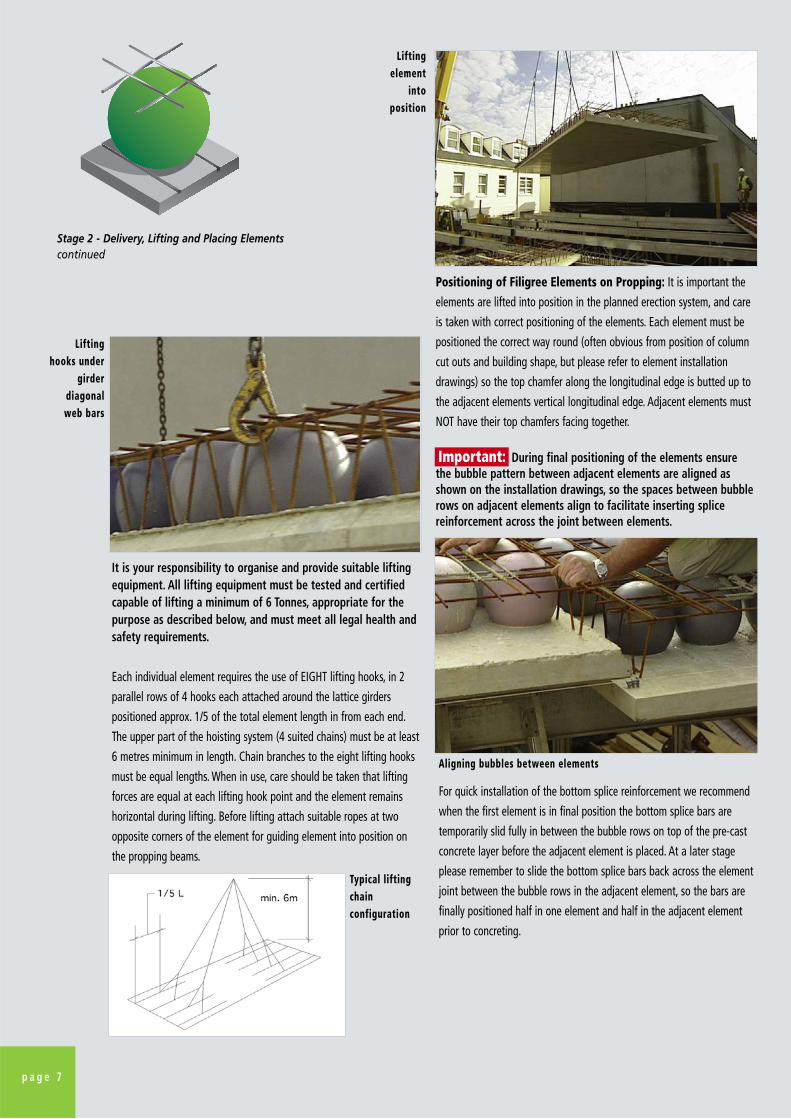
Positioning of Filigree Elements on Propping: It is important the
elements are lifted into position in the planned erection system, and care
is taken with correct positioning of the elements. Each element must be
positioned the correct way round (often obvious from position of column
cut outs and building shape, but please refer to element installation
drawings) so the top chamfer along the longitudinal edge is butted up to
the adjacent elements vertical longitudinal edge. Adjacent elements must
NOT have their top chamfers facing together.
Important: During final positioning of the elements ensure the bubble pattern between adjacent elements are aligned asshown on the installation drawings, so the spaces between bubblerows on adjacent elements align to facilitate inserting splicereinforcement across the joint between elements.

Stage 3 – Fixing Loose Site Reinforcement.We provide site installation drawings for loose site reinforcement (supplied by others)fixed at the bottom of the slab (directly on top of the pre-cast concrete filigreepermanent formwork without spacers or on top of site shuttering on spacers) andreinforcement fixed at the top of the slab (directly onto top mesh reinforcement),together with accompanying bar bending schedules. These must be studied and closelyfollowed at all times, if you have any question please call our Site Advisor/Inspector orHead Office for assistance. The sequence for fixing loose reinforcement is at yourdiscretion, however we recommend the following procedure is adopted:-
Cut-Outs, Recesses and Service Holes: During the manufacturing
process polystyrene void formers are fixed in these locations to create
areas without any concrete bottom biscuit. During erection of the
elements these are quickly broken out with a suitable chisel and mallet.
Sliding bottom splice bar central over joints
Lattice beam girderDo not cut top bar
Do not cut diagonal bars
Installation / Fixing Procedure
Inserted loose between every bubble directly on top of the pre-cast concrete biscuit permanent formwork. If they have beeninserted into one element during lifting elements into position,as we recommend, then simply slide the bars across the jointbetween adjacent elements to sit with equal lengths both sidesof the joint between elements.
Inserted loose between bubbles in positions shown on drawingsacross holes, openings and returns in slabs where applicable
Where applicable assemble bars into cages and fix between and / or around columns (as shown on drawings)
Slide hairpins in between bubble rows and slide in top / middle/ bottom edge bars around slabs perimeter, tying to hairpins asshown on drawings
Insert bottom bars across columns directly on top of the pre-cast concrete bottom formwork. Fix bars over top meshreinforcement (between the bubbles) across and around columnheads as shown on drawings, tying in place to mesh.
Note: where shear studs or shear rails have been pre-cast intoelement at factory there may not be any bars to be fixed on site.
Element joint splice reinforcement comprising either individualshort bars or purpose made mesh sheets (supplied by others)are placed with the bars between bubble rows and tied in placeequally across the joint between adjacent elements. In certainareas, for engineering reasons, additional top bar reinforcementwill be required (supplied by others) which must be laidbetween bubble rows (not across top of bubbles) directly ontoand tied to top mesh reinforcement, as shown on the drawings.The first layer of top additional bar reinforcement must be laidacross top of lower bars of top mesh reinforcement to avoidunnecessarily reducing top concrete cover.
As building configurations vary it is not possible to describe allpossible non-typical loose reinforcement configurations (such ascages for steps between main slab and cantilever slab) requiringsite fixing. This non-typical reinforcement will be shown anddetailed on the site installation drawings.
TypicalReinforcementType1. Bottom Joint
Splice Bars
2. Bottom Shear Bars
3. “Beam Strips” within Slab Depth
4. Perimeter Hairpins / Bars
5. Column Shear Reinforcement
6. Top Joint /Top barReinforcement
Other Loose Reinforcement
p a g e 8
U N I T E D K I N G D O M
R
Site Adjustment of Filigree Elements: The filigree elements are
designed and manufactured to suit the buildings configuration and
column / wall layout. They arrive on site with cut-outs / recesses /
steps for column or wall positions (including a 50-100mm
construction tolerance margin between r.c. columns / walls and the
pre-cast concrete layer) and larger service holes already formed,
therefore they should not require any site adjustment. However it
has been known for columns to be erected out of position on site
and in this unusual event it is possible to carefully alter the filigree
element with a disc cutter to maintain the margin between r.c.
columns / walls and the elements pre-cast concrete biscuit.
Important: The upper and diagonal bars in the latticebeam girder reinforcement must NOT be cut on site as theyhave an important structural function both during lifting andonce in place.
Important: Top joint and additional bar reinforcement first layer must be laid between bubble rows (not across top of bubbles) straight onto top of lower bars of top mesh reinforcement to avoid excessive layers of steel and difficulty with achieving required concrete cover.

Stage 4 – Constructing ShutteringOnce the perimeter loose reinforcement has been
installed work on erecting perimeter and
construction joint shuttering can commence.
Temporary works are your responsibility to
determine, but our recommendations are:-
Stage 5 – Preparation for
ConcretingThe pre-cast concrete permanent formwork edges are
manufactured to a high accuracy and care taken to get
a tight joint during laying the elements can render joint
filling unnecessary. When joints between slab elements
have not been closely butted they must be filled to
prevent grout seepage. Should this be required joint
filling can be undertaken with either mortar grout or a
small bead of silicone sealant inserted at the bottom of
the splay joint between elements. This is most easily
undertaken prior to installing the loose splice
reinforcement.
– expanding foam must NOT be used for jointfilling as the uncontrollable thickness canadversely reduce concrete cover to splicereinforcement impairing durability and fireresistance of the finished slab.
Prior to pouring topping concrete remove element
labels, unused tying wire, unused reinforcement, loose
concrete and all other debris or foreign matter. Then
immediately before placing in-situ concrete power-wash
top of the pre-cast concrete permanent formwork to
clean off residual dirt and moisten the pre-cast concrete
surface.
– maintain the pre-cast concrete biscuit topsurface, particularly during hot weather, in a damp(not wet) condition to ensure a good bondbetween the pre-cast concrete permanentformwork concrete and the in-situ concrete.
Shuttering Erection Procedure
Cut sheet of 18mm ply into strips to width of finished slabdepth. Fix 75x50mm battens along back edge at top andbottom. Where BD element is tight to edge of finished slabsimply plug and screw through bottom batten & ply shutteringstraight into centre of pre-cast concrete permanent formworkedge. Fix top of ply shuttering by wire tying back to top meshreinforcement from screws fixed into top batten.
When an in-situ concrete edge strip has been planned to makeup the overall floor-plate width then construct perimetershuttering with timber gallows brackets & plywood perimeter /soffite shuttering in traditional manner, except bracket bottombatten can be plugged and screwed to underside of pre-castconcrete permanent formwork.
Cut sheet of 18mm ply into strips 150mm wide, plug and screw50x50 battens to face of r.c. columns / walls (top 18mm belowslab soffite), slide ply into position. Plug and screw externaledge of ply shuttering into underside of pre-cast concretepermanent formwork.
* Note: When our combined column / wall andBubbleDeck construction method is adopted (see page 6)the pre-assembled column / wall formwork top flangeeliminates any need for this operation.
Cut sheet of 18mm ply into strips 180mm wide and prop up tounderside of pre-cast concrete permanent formwork.
Location
Perimeter Shuttering
Construction Tolerancemargin around r.c.columns / walls *
Construction tolerancejoints between groups of elements
Note: We can manufacture and supply pre-cast into
edge of elements a pre-foabricated “BubbleDeck Quick
Edge” steel permanent formwork, eliminating the need
for constructing perimeter shuttering on site – enquire
for further details at time of placing order.
p a g e 9
Important:
Important:

Stage 6 – BubbleDeck Site
InspectionOnce you are able to predict when all
loose reinforcement will be fixed
please contact our Site
Advisor/Inspector to notify the date
you intend to pour concrete and
arrange our site inspection. He will
then arrange for our technical
representative to visit site and
undertake a full inspection of the
BubbleDeck element and loose
reinforcement installation. Following
inspection our technical
representative will issue you with an
inspection record listing any work
that needs to be undertaken prior to
site concreting, or confirming the
installation is ready for concreting
and the work is to our approval.
– While we always seek to providea quick and efficient service wedo need at least 2 working daysnotice of any site concrete pour tobe able to ensure our inspectionteam are available to attend site.It is essential we are able toinspect prior to site concreting inorder to be able to cover yourproject with our ProfessionalIndemnity and Product LiabilityInsurance cover.
Stage 8 – Removing Temporary ProppingDuring construction planning we will confirm to you the minimum period for removal of propping before back-propping.
This is usually between 3 to 5 days from pouring of the site concrete as long as the early concrete test results have
confirmed the site concrete has reached at least 60% of its final design strength, but can vary dependant upon our floor
slab design, strength of site concrete, and ambient temperatures.
Once you have received the 3-5 day concrete test results please forward them to our Head Office, our technical team will
then confirm to you it is acceptable to remove temporary propping. If you are then proceeding to construct another floor
immediately above the one just completed please refer to the section about Back Propping on Page 5 of this Manual.
Subsequent Site OperationsLightweight FixingsThere is a minimum of 20mm concrete below the centre of each bubble, but just a short distance away from the bubble centre theconcrete depth quickly increases to 70mm plus up the side of each bubble. Therefore fixings for attaching light and medium weightarticles can be made using normal methods (plug & screw / expanding anchors, etc.) to provide adequate fixings for wiringconduits, small cable trays, small ventilation ducts and the like.
Heavy Weight FixingsWhere stronger fixings are required to resist higher pull out (downward) forces from heavy loads to be suspended from the soffitewe recommend our Bubble layout drawings are inspected to determine where fixings will occur directly below or close to the edgeof a bubble. Where fixing locations and lengths are likely to project into a bubble void we recommend Hilti HIT HY20 InjectionResin Anchor with HIT sieve, item no. 00068613, are used. Hilti also produce a range of other fixing systems designed for fixingthrough into voids.
Holes through slabsHoles can easily be diamond core drilled through the completed BubbleDeck slab. Due to the two way spanning attributes ofBubbleDeck slabs there are few limitations on the positioning of holes, except near columns where loads are transferred from theslab into the columns and shear forces are highest.
Service risers larger than 250mm square should be designed into the slab for forming in the factory & boxed out on site prior topouring insitu concrete. Pipe holes up to around 250mm diameter are best diamond core drilled after casting of slabs to ensureoptimum vertical alignment. There is great flexibility where these can be placed because the slab will span around such holes. Theonly limitations are to avoid cutting off too much support when holes are formed near supporting columns / walls, or a series ofholes in a row in certain situations, but these can be allowed for during design stage.
Prior to forming holes in completed slabs larger than 250mm diameter, within 500mm of a supporting column / wall, or multiple holes in close proximity please refer to our Technical Department for advice before undertaking such works.
When pouring concrete
evenly distribute across
the area and avoid placing
in heaps. Due to the
limited space between the
bubbles a thin vibrating
poker MUST be used to compact the concrete,
remove any entrained air and to ensure a good flow around the bubbles. Avoid separation occurring due to the vibrating
of shuttering, reinforcement and/or bubbles that can result in segregation of the concrete mix. Once the concrete has
been poured a steel beam or power float is then used to level the top and finish to an even and level surface.
Pouring, Vibrating& Floating Site
Concrete
Overall Slab Depth (inc. pre-cast filigree)
230 mm280 mm340 mm390 mm450 mm510 mm600 mm
Concrete pour Volume m3 / m2 plan area
0.1120.1470.1920.2240.2710.3160.374
Max aggregate size
10mm10mm15mm15mm15mm15mm15mm
BubbleDeck Slab TypeBD230- ABD280 -ABD340 -ABD390 -ABD450- ABD510- ABD600- A
Stage 7 – Pouring Topping ConcreteWhen ordering concrete please take into account the volume taken up by the
bubble void formers mean the concrete volume is NOT arrived at by taking the pour area xdepth from top of shuttering to pre-cast concrete permanent formwork. The concrete volume toorder can be estimated, dependant upon BubbleDeck slab depth type, from the following table:-
p a g e 1 0
U N I T E D K I N G D O M
R
Important:
Important:

BubbleDeck Site Erection & Installation ManualEdition 6 September 2008
C o n t a c t d e t a i l s
BubbleDeck UK (2008) LtdWhite Lodge, Wellington Road,St Saviour, JERSEY, Channel Islands, JE2 7TE
Telephone: +44 (0)1534 725402Facsmile: +44 (0)1534 739115
E-Mail: [email protected]. BubbleDeck-UK.com
U N I T E D K I N G D O M
R