Embed Size (px)
Citation preview

Electronic Supporting Information
Site-Specific Growth of Polymer on Silica Rods
Bo Peng,*a Giuseppe Soligno,b Marlous Kamp,a Bart de Nijs,a Joost de Graaf,a Marjolein Dijkstra,a René van Roij,b Alfons van Blaaderen,*a and Arnout Imhof*a
a Soft Condensed Matter, Debye Institute for Nanomaterials Science, Utrecht University, Princetonplein 5, 3584 CC Utrecht, The Netherlands* E-mail: [email protected]; [email protected]; [email protected]
b Institute for Theoretical Physics, Center for Extreme Matter and Emergent Phenomena, Utrecht University, Leuvenlaan 4, 3584 CE Utrecht, The Netherlands
Electronic Supplementary Material (ESI) for Soft Matter.This journal is © The Royal Society of Chemistry 2014

Table of Contents
Experimental section ..................................................................................................................3
Materials ..............................................................................................................................................3
Procedure for silica rods synthesis.......................................................................................................4
Procedure for TPM coating..................................................................................................................5
Procedure for hybrid polymer-silica particles synthesis......................................................................5
Purification of the hybrid particles from the polar solvent ..................................................................7
Procedure for dying the particles .........................................................................................................7
Characterization ...................................................................................................................................8
Electric field.........................................................................................................................................9
Experimental results.................................................................................................................11
Vectorial orientation of lollipop particles ..........................................................................................20
Numerical evaluation of rod-liquid adsorption surface free energies ......................................21
Rods with homogeneous surface properties ......................................................................................21
Rods with heterogeneous surface properties .....................................................................................27
Supplementary references ........................................................................................................31

Experimental section
Materials
In the synthesis of silica rods: tetraethyl orthosilicate (TEOS, 98%, Aldrich) was used as the
precursor for the silica rods. Ammonia (NH3, 29 wt% solution in water, Merck) was used as
the catalyst. Poly(vinylpyrrolidone) (PVP, K-30, Aldrich) with an average molecular weight
of 40,000 g/mol, 1-pentanol (≥ 99%, Sigma), ethanol (chemical grade, Baker), and sodium
citrate dihydrate (≥ 99%, Sigma) were used as received. De-ionized water was used in all
experiments and was obtained from a Millipore Direct-Q UV3 reverse osmosis filter
apparatus.
In the preparation of hybrid particles: Methyl methacrylate (MMA, Aldrich) was
passed over an inhibitor removal column (Aldrich) at room temperature. After the inhibitor
was removed, MMA was stored in a refrigerator at +4 oC for not longer than 1 month.
Styrene (St, Fluka) was passed through a homemade activated alumina filled column to
remove the inhibitor and used immediately. Azo-bis-isobutyronitrile (AIBN, Janssen
Chimica) was re-crystallized from ethanol before use. Poly(vinylpyrrolidone) (PVP, K-90,
Fluka) with a molecular weight of 360,000 g/mol and PHSA-g-PMMA (a poly(12-
hydroxystearic acid) (PHSA) grafted PMMA copolymer) were used as stabilizers. The
PHSA-g-PMMA stabilizer, dissolved in a mixture of ethyl acetate and butyl acetate, was
homemade and its synthesis is described by Antl et al.s1 Rodamine b isothiocyanate (Aldrich)
was used as fluorescent dye. 1-Octanethiol (≥ 98.5%, Aldrich), methanol (chemical grade,
Biosolve), acetone (chemical grade, Baker), hexane (chemical grade, Biosolve), dodecane (>
99%, Sigma-Aldrich), sulfuric acid (95%, Fisher), and hydrogen peroxide (35% in water,
Merck) were used as received.
3-(Trimethoxysilyl) propyl methacrylate (TPM, 98%, Aldrich) was used as the coupling
agent between silica rods and PMMA. Hydrofluoric acid (HF, 48 wt% in H2O, Sigma-

Aldrich) was diluted to about 5 wt% with de-ionized water and then used to selectively etch
the silica rods.
Procedure for silica rods synthesis
The silica rods were synthesized using the method detailed in previous papers.30, 33 Typically,
bullet-shaped rods with a length of 737 nm and a diameter of 384 nm were prepared as
follows: 80 ml of PVP (K-30) was dissolved in 800 ml of 1-pentanol by sonication until all
PVP was dissolved, and placed in a 1 L glass flask. Then, 80 ml of ethanol, 40 ml of de-
ionized water and 8 ml of 0.18 M sodium citrate dihydrate aqueous solution were added to
the PVP/pentanol mixture. The flask was shaken by hand for 2 min. Subsequently, 16 ml of
ammonia was added, and the flask was shaken again by hand. Then, 8 ml of TEOS was added
to the mixture, and briefly shaken to mix the content. The flask was left to rest and the
reaction was allowed to proceed for 36 h. The length of the rods can be readily tuned by
using various amounts of water. More details can be found in refs. 30 and 33. After the
reaction the silica rods were thoroughly cleaned by centrifugation and re-dispersion in
ethanol by sonication 4 times, and finally dried with a nitrogen stream at room temperature.
The morphology of the rods can be easily tuned by growing silica layers in a precise
way using seeded growth.30, 33, 37 For the 15 nm thick silica layer, 0.4 g of silica rods was
dispersed by sonication in a mixture consisting of 40 ml ethanol, 1.3 ml water and 1.6 ml of
ammonia. Then, 0.2 ml of TEOS was added. The reaction was allowed to proceed for 24 h.
For the rods with two rounded ends, a ~150 nm thick silica layer was grown on the original
silica rods. This process can be achieved through a multi-step growth of silica layers using in
total of 7 ml TEOS. The final products were washed three times with ethanol and dried at
room temperature.
In one experiment the rods were treated with a piranha solution (sulfuric acid and
hydrogen peroxide at a 3:1 v/v ratio) to clean their surface from organic residues. First, the

dried rods (~ 0.05 g) were dispersed in sulfuric acid (~ 9 ml) by sonication. Then, hydrogen
peroxide (~ 3 ml) was added to the suspension of rods, and the dispersion was stirred
overnight. The next day, the rods were separated by centrifugation and rinsed with de-ionized
water until the pH was close to 7. Finally, the rods were dried at room temperature for further
use.
Procedure for TPM coating
To provide a basis for the PMMA to react to, the silica rods were treated with the coupling
agent 3-(trimethoxysilyl) propyl methacrylate (TPM). Typically, 0.3 g of dried rod-like silica
particles were dispersed in 5 ml of ethanol after which 1 ml of ammonia and 3 ml of TPM
were added. The mixture was sonicated for 1 min to disperse the rods. The mixture was then
stirred for 3 h at a moderate stirring rate (~100 rpm) at room temperature. After this
procedure, the suspension was transferred to a 50 ml round bottom flask and vacuum distilled
at room temperature to promote the condensation reaction as Philipse et al.s2 described. After
about 20 min, 1-2 ml bright, gel-like suspension remained at the bottom of the flask, and the
distillation was stopped. This TPM grafted silica (named TPM-SiO2) was purified by 3 cycles
of centrifugation/re-dispersion in methanol. The final samples were dispersed in methanol
and stored at +4 oC for no longer than one week.
Procedure for hybrid polymer-silica particles synthesis
Hybrid PMMA-silica particles were synthesized through the co-polymerization of TPM
grafted silica rods with methyl methacrylate (MMA) in a polar medium. Typically, a mixture
containing 0.4 g PVP (K-90), 0.051 g TPM-SiO2 rods, and 4.1 g methanol was prepared.
Then, MMA containing 1 wt% of initiator (AIBN) was added. This reaction mixture was
deoxygenated for 1 h by bubbling nitrogen through the mixture. Subsequently, the flask with
this mixture was placed in a pre-heated silicone oil bath and maintained at 55 oC, and stirred
at 100 rpm for 24 h before cooling down to room temperature. The obtained particles were

rinsed three times with methanol using a centrifuge (Hettich Rotina 46 S, at 315 g for 20 min).
The products were stored in methanol for further purification to remove the free polymer
particles by sedimentation. By simply scaling up the reaction (e.g., five times the initial
quantities), the yield of the rods increased, while the quality remained the same, and the result
is shown in Figure S1a.
Hybrid PS-silica particles were synthesized in a similar way to that of PMMA-silica
particles. In detail, 0.1 g PVP (K-90), 0.05 g TPM-SiO2, and 4.1 g ethanol mixed
homogeneously by sonication for 1 min, and then, St (~ 0.24 g) containing 1.2 wt% of
initiator (AIBN) was added to the mixture. A de-oxygenation (N2 bubbling through the
mixture for around 1 h) was carried out prior to the co-polymerization. Co-polymerization
took place at 70 oC, and was continued for 24 h. The products were washed with ethanol at
315 g for 20 min (Hettich Rotina 46 S) three times to remove the un-bonded stabilizer and
monomer, and stored in ethanol for further purification to remove the free polymer particles.
The result is shown in Figure S1b.
Based on the recipe aforementioned recipe, a variety of hybrid particles was
successfully prepared by making use of silica rods that had undergone diverse treatments.
To selectively remove the silica from hybrid particles, hydrofluoric acid (HF) was used and
diluted to about 5 wt% with de-ionized water first. Then, HF aqueous solution was added in
excess to the suspension of hybrid particles (~ 0.1 wt% in water), and kept stirring (~ 100
rpm) for 30 min. Subsequently, the particles were rinsed three times with de-ionized water to
purify the residue of the hybrid particles, and the final product was stored at room
temperature for characterization.
In the dispersion polymerization where silica rods rather than PVP acted as the
stabilizer, the procedure was similar to the dispersion polymerization just described.
Typically, 0.05 g of TPM-SiO2 rods was dispersed in 4.1 g of methanol. Then, various

amounts of MMA containing 1wt% (based on the monomer mass) of AIBN were fed into the
dispersion of rods under constant stirring (~ 100 rpm). After 1 h of deoxygenation, the flask
was immersed in the silicone oil bath at 55 oC and maintained for 24 h. After the reaction was
complete, the un-reacted MMA was removed by three rinse cycles with methanol, and the
obtained product was stored in methanol for observation.
Purification of the hybrid particles from the polar solvent
The synthesis of hybrid particles also results in a number of free PMMA particles. In order to
purify the hybrid particles, a mixture of glycerin and water was used in combination with a
centrifuge (Hettich Rotina 46 S), to separate the hybrid particles from the mixed system. An
empirical weight ratio (α) between glycerin and water was used, calculated by:
(S1)wgwm
gmwg
where ρg, ρw and ρm are the density of glycerin (1.261 g/cm3), water (0.997 g/cm3) and
mixture of glycerin and water at 25 oC, respectively. Considering the density of PMMA of
about 1.18 g/cm3, we selected the density of the mixture (ρm = 1.20 g/cm3) to be slightly
higher than PMMA. The separation was carried out with a Hettich Rotina 46 S centrifuge, at
800 g for 5 hours. After the third purification, the particles dispersed in methanol and
centrifuged three times to remove the remainder of the glycerin/water mixture. Ultimately,
the obtained particles were stored in methanol for future use.
Procedure for dying the particles
The as-synthesized hybrid particles were labeled with a fluorescent dye. First, an amount of
hybrid particles (~ 0.1 g) was collected through a centrifugation process and the supernatant
was removed. Then, the hybrid particles were dispersed by sonication in 5 ml of pentanol
containing 1 mM of Rodamine b isothiocyanate (RITC) in a 20 ml glass vial. The suspension
was stirred at 100 rpm for 2 days at room temperature. Subsequently, the labeled particles

were washed twice with pentanol, once with methanol, and three times with de-ionized water,
respectively, by centrifugation. After drying under a nitrogen stream at room temperature, the
fluorescently labeled hybrid particles were stored in a dark glass vial for further observation.
In order to minimize interference from light scattering, refractive index matching
between the particles and solvent is desired. However, due to the fact that the particles are
made of two types of materials, fully refractive index matching is impossible. Considering
the refractive index of silica (1.45) and PMMA (1.49), we chose a mixture of glycerin and
water (roughly 9:1 in weight)s3 to refractive index match with the silica rods.
In fact, the following confocal scanning laser microscopy observation indicated that
the dye only partly penetrated into the particles, developing core-shell fluorescently labeled
particles (see the inset in Figure 1d).
Characterization
To determine the details (size, polydispersity and morphology and internal structure) of the
particles, transmission electron microscopy (TEM) was performed with a Philips Tecnai 10
(accelerating voltage ≤ 100 kV). A diluted sample suspension was deposited on a copper grid
coated with a polymer membrane which was carbon coated, and the sample was allowed to
dry at room temperature. Tomographic reconstructions were made by taking TEM images at
angles ranging from -70o to +70o with intervals of two degrees and aligned using gold
markers. The software used for alignment and reconstruction is the IMOD package made by
the Boulder laboratory in Colorado.34, 35 For the Tomogram generation the SIRT algorithm
was used with 70 iteration steps and a radial filter cut-off of 0.4 and falloff of 0.05.
Scanning electron microscopy (SEM) was carried out with a Philips XL30FEG
microscope to observe the surface morphology and shape of the particles. The samples were
prepared by placing a drop of dispersion on a grid and allowing the solvent to evaporate at

room temperature. The samples then were sputter-coated with a layer of platinum (Pt) about 3
nm.
Confocal scanning laser microscopy (CSLM) was used to help assess the structure of
the fluorescently labeled hybrid particles. The dried fluorescently labeled particles (~ 0.01 g)
were dispersed in the mixture of glycerin of water (~ 1 g, 9:1 in weight) in a small vial
(contents ~ 1 ml) with the help of a sonication bath. To be able to use the cell in the CSLM
setup, the bottom of the vial was removed and replaced with a thin cover glass, which was
glued to the vial using epoxy glue. A Nikon confocal scanning laser can head (Nikon C1) was
operated in fluorescence mode on a Leica (DM IRB) inverted microscope. Measurements
were performed with a Leica 100× oil confocal immersion lens with a numerical aperture of
1.4. The fluorescent particles were excited at around 543 nm, and their images were observed
at emission wavelengths of around 605 nm.
Electric field
Electric cells were prepared from capillaries with inner dimensions 0.1×1×5 mm. These
capillaries had been treated with 3-trimethoxypropylsilylmethacrylate prior to use, to counter
the sticking of particles to the capillary walls. Wire electrodes from Goodfellow (diameter
0.05 mm and composition 95% Ni, 5% Al/Mn/Si) were spanned along the sides. A HP
33220A 15 MHz Function/Arbitrary Waveform Generator provided sinusoidal electric fields
with 2V peak-to-peak voltage. A Krohn-Hite 7602M Wideband Amplifier was used for
amplification of the signal to 15-20V.
The electric cells were filled with a dispersion of lollipop particles in ethanol. This
dispersion was prepared from an aqueous dispersion by centrifugation, exchange of solvent,
and sonication in a Branson 2510 sonication bath. The dispersion was used directly after
preparation, since ethanol etches away the PMMA sphere in the course of a day. Prolonged
storage in water also seemed to reduce the described vectorial orientation in the electric field.

Electric field experiments were recorded on a Leica SP8 confocal microscope. This
microscope was equipped with a Plan Apo 63x oil immersion lens (NA = 1.32). Wavelengths
of 495 nm and 543 nm were selected from the spectrum of a white light laser by means of an
acousto-optical beam splitter (AOBS). Two detectors recorded in different imaging modes: a
PMT in reflection mode, and a more sensitive hybrid detector in fluorescence mode. The
fluorescence channel captured photons from a wavelength range about the emission
maximum of the rhodamine dye. The reflection channel was set to capture light of
wavelength 495 nm. In other words, this channel recorded scattering of light of 495 nm by
the particles. Scattering occurs due to the refractive index match mismatch between the
solvent (n = 1.362) and the particles (silica rods: n ~ 1.45, PMMA spheres: n = 1.49). We
were able to tune the gain of both channels such that only the spheres were visible in
reflection mode, due to the larger refractive index mismatch between the PMMA spheres and
solvent as compared to the silica rods and solvent. The silica rods were visible in the
fluorescence channel. The two channels were displayed in different 8-bit color look-up
tables: reflection mode in green and fluorescence mode in red. The final images were
acquired by overlaying these two channels.
We worked with AC fields rather than DC fields to eliminate (1) gathering of the
particles at the electrodes and (2) solvent hydrolysis. Frequencies of about 0.5 Hz appeared
slow enough to allow vectorial orientation. We needed at least five images per second for
accurate sampling of the motion. For this reason, scanning was bidirectional and at a speed of
1400 Hz, while the images had a rectangular shape with a resolution of 1024 by 512 pixels.
With these settings, the scanning rate was 5.24 frames/s.

Experimental results
Figure S1. a, Scanning electron microscopy (SEM) image of non-spherical hybrid silica-
PMMA particles prepared in bulk by using the monomer (methyl methacrylate, MMA) and
rods at a weight ratio of 4.85:1. This result was obtained by scaling up by five times the
recipe mentioned in the experimental section. b, Transmission electron microscopy (TEM)
image of lollipop-shaped hybrid particles prepared by using styrene and rods at a weight ratio
of 4.85:1. The scale bars are 2 µm.

Figure S2. TEM image of hybrid particles obtained 20 minutes after the start of the
polymerization of MMA in the presence of silica rods as seeds. It clearly indicates that
primary nuclei of monomer were preferentially, but not exclusively, attached to the flat ends
of the silica rods. The scale bars are 2 µm in the main figure and 500 nm in the insets,
respectively.
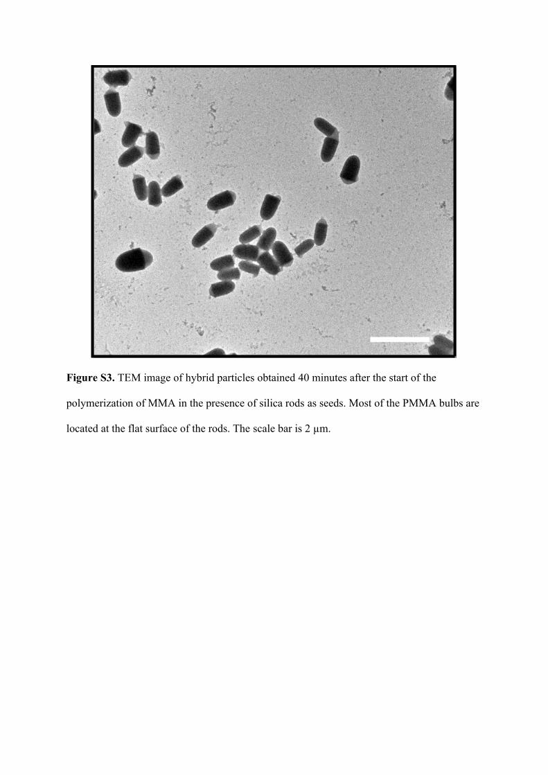
Figure S3. TEM image of hybrid particles obtained 40 minutes after the start of the
polymerization of MMA in the presence of silica rods as seeds. Most of the PMMA bulbs are
located at the flat surface of the rods. The scale bar is 2 µm.

Figure S4. TEM image of a system prepared with bare silica rods (without TPM treatment)
and monomer (MMA). Clearly, PMMA did not attach to the rods. The scale bar is 2 µm.

Figure S5. Transmission electron microscopy (TEM) image of snowman-shaped silica-
PMMA particles, made by using TPM-SiO2 spheres instead of the silica rods. It indicates that
the TPM modified silica surface was partially wetted with PMMA. The scale bar is 2 µm in
the main figure and 200 nm in the inset, respectively.

Figure S6. TEM image of core-shell PMMA-silica particles prepared in apolar solvent
(mixture of hexane and dodecane, the recipe is originally from supplementary ref. 1). The
scale bar is 2 µm in the main figure and 200 nm in the inset, respectively.

a
b
Figure S7. TEM images of PMMA attached silica rods that have been coated with an
additional layer of 15 nm of silica. a, short rods (aspect ratio is about 2.4). b, long rods
(aspect ratio is about 3.8). The silica/MMA mass ratio was 9.7:1. The scale bars in a) and b)
are 1 and 2 µm, respectively.

Figure S8. TEM image of lollipop-shaped hybrid particles by using piranha-cleaned silica
rods. Most of the PMMA is at the flat end of the silica rods, but small secondary PMMA
bulbs are also present. The scale bar is 2 µm in the main figure and 200 nm in the inset,
respectively.

Figure S9. TEM images of PMMA bulbs attached to the silica rods side-on, after the silica
rods had been calcined at 500 oC for 2 h. The silica/MMA mass ratio was 9.7:1. The scale bar
is 2 µm in the main figure and 200 nm in the inset.

Vectorial orientation of lollipop particles
The lollipop particles showed a clear orientation in the field with their silica rods towards one
of the electrodes and their PMMA spheres towards the other. In a field of frequency 400 mHz
and strength 15-20 V/mm, the particles followed the field by preferentially rotating the silica
rods. In this way, the particles could be aligned ‘vectorially’. The particles turned their silica
rods towards one electrode, underwent electrophoresis towards that electrode, and turned
around towards the other electrode as the field inverted. A DC field also oriented the particles
to one electrode, but such a field quickly induced drift in the samples.
At higher frequencies, on the order of 10 Hz, the particles were unable to follow the
field orientation and displayed only Brownian motion. At very high frequencies, on the order
of a 1 MHz, the particles were aligned in the field as a result of dipolar interaction with the
field, yet the orientation of lollipop-shaped particles was in random.
Figure S10. Uniform orientation of anisotropic silica-PMMA particles aligned by electric
field (green reflection signal, red fluorescence). The scale bar is 5 µm.

Numerical evaluation of rod-liquid adsorption surface free energies
Rods with homogeneous surface properties
The strategy that we used to determine the behavior of bullet-shaped particles with
homogeneous surface properties adsorbed to the flat interface between two liquids is the
theoretical method of refs. 43 and 44. This method is the so-called triangular-tessellation
technique, in which the surface of the particle is approximated by a large number of small
triangles. The quality of the approximation of the object by a triangular mesh can be
improved upon by increasing the number of triangles, thereby reducing the size of the
individual triangles. In this model, only one particle is considered at a flat fluid-fluid interface.
The free energy of adsorption associated with this system is governed solely by the surface
areas of fluid-fluid and particle-fluid interfaces, thereby ignoring line tension contributions
from the three-phase contact-line. This is in the spirit of the early studies on colloid
adsorption by, e.g., P. Pieranski.s4 The free energy of adsorption may be written as
(S2) ,, 22111212 constSSSAzV cc
where S1 is the surface area of the particle with fluid 1 above the interface, while S2 is the
surface area of the particle with fluid 2 below the interface; A is the total surface area
between fluid 1 and fluid 2, and S12 is the area excluded from that interface by the presence of
the particle. γ12, γ1c and γ2c are the surface tensions between phase 1 and 2, and the particle;
and the constant in Equation S2 can be tuned to set the energy of the particle completely
immersed in fluid 1 to zero. The adsorption free energy in Equation S2 depends through the
surface areas on z (the distance of the interface with respect to the center of the particle) and
ϕ (the polar angle, which measures the angle between the particle’s rotational symmetry axis
and the interface normal, ranging from 0 to π). A schematic model can be found in Figure
S11.

We define the state in which the particle is fully immersed in phase 1 as a reference
state. In this case, the relative free energy is written as
(S3) ,,, 1212121112 SSSSAzVzF ccc
where S is the total surface area of the particle (S = S1 + S2). When the particle is completely
encompassed by phase 1, F(z,ϕ) is zero. The dependence can be written using cc 21
Young’s equation,s5
(S4),cos 2112 cc
such that Equation S3 becomes
(S5) .cos, 12112 SSSzF
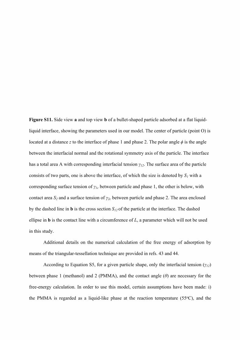
Figure S11. Side view a and top view b of a bullet-shaped particle adsorbed at a flat liquid-
liquid interface, showing the parameters used in our model. The center of particle (point O) is
located at a distance z to the interface of phase 1 and phase 2. The polar angle ϕ is the angle
between the interfacial normal and the rotational symmetry axis of the particle. The interface
has a total area A with corresponding interfacial tension γ12. The surface area of the particle
consists of two parts, one is above the interface, of which the size is denoted by S1 with a
corresponding surface tension of γ1c between particle and phase 1, the other is below, with
contact area S2 and a surface tension of γ2c between particle and phase 2. The area enclosed
by the dashed line in b is the cross section S12 of the particle at the interface. The dashed
ellipse in b is the contact line with a circumference of L, a parameter which will not be used
in this study.
Additional details on the numerical calculation of the free energy of adsorption by
means of the triangular-tessellation technique are provided in refs. 43 and 44.
According to Equation S5, for a given particle shape, only the interfacial tension (γ12)
between phase 1 (methanol) and 2 (PMMA), and the contact angle (θ) are necessary for the
free-energy calculation. In order to use this model, certain assumptions have been made: i)
the PMMA is regarded as a liquid-like phase at the reaction temperature (55oC), and the

interfacial tension γ12 is the surface tension between PMMA and methanol; ii) Due to fact that
methanol completely wets solid PMMA,s6, s7 the exact value of the interfacial tension is
unknown and therefore we examine values in the range 0.1 to 0.0001 N/m;s6, s8 iii) the contact
angle (θ) between TPM-SiO2, PMMA and methanol is not significantly changed by the
solidification of PMMA, and the presence of PVP in the system, and can thus be determined
from the experiment, see below; iv) The line tension contribution is neglected throughout,
since it typically has a small value on the order of 10-11 N.s9, s10
The contact angle of 115o (± 10o) is obtained based on the TEM images of samples
shown in Figure 1b and c, which was considered to be the valid contact angle (θ0) on the
spherocylindrical surface (shaft of the bullet) after the polymerization stopped. That is, the
contact angle present in the nascent stage of the polymer attachment is varying and we deem
it inaccurate to use images from this time to evaluate the contact angle, in light of the fact that
the polymer is very soft during growth. This variation of the contact angle can be appreciated
from Fig. 2. Therefore, the contact angle was measured only after when the polymer bulb
stopped growing; it has totally solidified and spilled over sharp edge separating the flat end
from the shaft of the bullet. This final value can therefore be considered to be a measure for
the contact value (θ0) on the shaft of the spherocylinder. Furthermore, we assumed that
curvature effects would not significantly influence the contact angle measurement.
The adsorption energy minimized with respect to z is plotted as a function of the
orientational angle ϕ of the particle in Figure S12. It is seen that a horizontal orientation has a
lower free energy than a perpendicular one, and that the two states are separated by a large
free-energy barrier. Even if a very small value of interfacial tension γ12 is adopted, e.g.,
0.0001 N/m,s8 the free-energy barrier between the metastable state and the equilibrium state is
still significant (715 kT). We also plot the adsorption free-energy barrier as a function of
interfacial tension in Figure S13. It clearly shows that the energy barrier depends linearly

upon the interfacial tension, as is also evident from Equation S5. Our result implies that once
a rod is attached end-on to a PMMA droplet/bulb, it is unlikely to reorient to a parallel
configuration due to thermal fluctuations, despite it not being a thermodynamically favored
state. However, since in the hedgehog-like assemblies the bullets are exclusively found in the
end-on configuration, the possible stability of the end-on configuration is to be investigated.
As also explained in the main text, a possible source of such stability could be a chemical
heterogeneity on the surface of the bullet, in particular between the flat bottom and the shaft
of these colloids, in light of the preferential nucleation of PMMA on the former.
Figure S12. The minimum adsorption free-energy curve (Fmin) with θ = 115o and supposed
interfacial tension of 0.0001 N/m for the bullet-shaped particle (L = 737 nm and D = 384 nm)
adsorbed at the interface of two liquids. The polar angle between the interfacial normal and
the rotational symmetry axis of the colloids is denoted by ϕ (also see Figure S9). The insets
show schematic images of the configuration of the particle at the interface, 1kT = 4.11×10⁻²¹
N·m.

Figure S13. The surface free-energy barrier between the maximum and the metastable
minimum as a function of interfacial tension γ12, based on our calculation. The contact angle
is 115o.

Rods with heterogeneous surface properties
Our calculation of the free energy of the particles with homogeneous surface chemistry at the
flat interface can also be extended to patchy colloid particles, i.e., particles with patches with
different surface tensions (see Figure S14).
Figure S14. Schematic graph of a patchy colloidal particle.
This means that to every i-th patch we can associate a cosine of the contact angle
cosθi. In the case of a colloidal particle with a general shape and with N different patches, its
free energy at the interface becomes:
, (S6)
N
ii
ii SSSzF1
1212112 cos,
where is the surface of the i-th patch that is immersed in phase 1, and S(i) is the total )(1
iS
surface of the i-th patch.

Figure S15. Contour plot of the orientation ϕ (see Figure S9a) of the long rods (aspect ratio is
4.2) configuration with minimum free energy, as a function of the contact angle θ1 (flat base
of the bullet-shaped rods) and θ0 (remaining surface).

Figure S16. Behavior of a bullet-shaped particle (aspect ratio is 4.2, diameter = 1386 nm and
length = 331 nm) adsorbed at the interface with cos0 and various values of cos1.
1kT = 4.11×10⁻²¹ N·m.

Figure S17. Normalized adsorption free energy difference (Δf) between the metastable and
stable state of the bullet-shaped rods (aspect ratio is 4.2) adsorbed at interface.
The relation between the orientation ϕ of the rods with an aspect ratio of 4.2 and
contact angles of 0 and 1 is plotted in Figure S15. Similar to the short rods (aspect ratio is
1.9), there are two distinct regions present where the end-on attachment of the rod to the
interface is preferred. However, when cos0 assumes the value of -0.42 from the
experimental observation, the only stable configuration of rods with minimum adsorption free
energy is always the side-on attachment to the interface regardless of the value of 1 (see
Figure S16). This is clearly shown in Figure S17, where the normalized adsorption free
energy difference (ΔF) remains positive. Thus, we can conclude that the surface chemistry
heterogeneity on a long bullet is not sufficient to stabilize the end-on attachment on the
interface.

Supplementary references
[1] L. Antl, J. W. Goodwin, R. D. Hill, R. H. Ottewill, Colloids and Surface 1986, 17, 67.
[2] A. P. Philips, A. Vrij, J. Colloid Interface Sci. 1989, 128, 121.
[3] U. Dassanayake, S. Fraden, A. van Blaaderen, J. Chem. Phys. 2000, 112, 3851.
[4] P. Pieranski, Phys. Rev. Lett.1980, 45, 569.
[5] T. Young, Phil. Trans. R. Soc. Lond. 1805, 95, 65.
[6] J. R. Dann, J. Colloid Interface Sci. 1970, 32, 302.
[7] A. Zdziennicka, Colloid Surface A. 2010, 367, 108.
[8] W. A. Zisman, in Contact Angle, Wettability, and Adhesion, Vol. 43 (Ed: F. M.
Fowker), American Chemical Society, Washington, DC, 1964, pp. 1-51.
[9] J. S. Rowlinson, B. Widom, Handbook of Surface and Colloid Chemistry; Dover
Publication, Midneola, 1st edition, 2003.
[10] A. Amirfazli, A. W. Neumann, Adv. Colloid Interface Sci. 2004, 110, 121.