Embed Size (px)
Citation preview

Site Preparation and Planning
This chapter describes the site preparation and planning for your mesh network and contains the followingsections:
• Site Survey, page 1
• Wireless Mesh Network Coverage Considerations, page 8
• Indoor Mesh Interoperability with Outdoor Mesh, page 34
Site SurveyWe recommend that you perform a radio site survey before installing the equipment. A site survey revealsproblems such as interference, Fresnel zone, or logistics problems. A proper site survey involves temporarilysetting up mesh links and taking measurements to determine whether your antenna calculations are accurate.Determine the correct location and antenna before drilling holes, routing cables, and mounting equipment.
When power is not readily available, we recommend you to use an unrestricted power supply (UPS) totemporarily power the mesh link.
Note
Pre-Survey ChecklistBefore attempting a site survey, determine the following:
• How long is your wireless link?
• Do you have a clear line of sight?
•What is the minimum acceptable data rate within which the link runs?
• Is this a point-to-point or point-to-multipoint link?
• Do you have the correct antenna?
• Can the access point installation area support the weight of the access point?
• Do you have access to both of the mesh site locations?
Cisco Wireless Mesh Access Points, Design and Deployment Guide, Release 8.6 1

• Do you have the proper permits, if required?
• Do you have a partner? Never attempt to survey or work alone on a roof or tower.
• Have you configured the 1500 series before you go onsite? It is always easier to resolve configurationor device problems first.
• Do you have the proper tools and equipment to complete your task?
Cellular phones or handheld two-way radios can be helpful to do surveys.Note
Outdoor Site SurveyDeployingWLAN systems outdoors requires a different skill set to indoor wireless deployments. Considerationssuch as weather extremes, lightning, physical security, and local regulations need to be taken into account.
When determining the suitability of a successful mesh link, define how far the mesh link is expected to transmitand at what radio data rate. Remember that the data rate is not directly included in the wireless routingcalculation, and we recommend that the same data rate is used throughout the same mesh.
Design recommendations for mesh links are as follows:
• MAP deployment cannot exceed 35 feet in height above the street.
• MAPs are deployed with antennas pointed down toward the ground.
• Typical 5-GHz RAP-to-MAP distances are 1000 to 4000 feet.
• RAP locations are typically towers or tall buildings.
• Typical 5-GHz MAP-to-MAP distances are 500 to 1000 feet.
• MAP locations are typically short building tops or streetlights.
• Typical 2.4-GHz MAP-to-client distances are 500 to 1000 feet (depends upon the type of access point).
• Clients are typically laptops, Smart Phones, Tablets, and CPEs.Most of the clients operate in the 2.4-GHzband.
• In release 8.2 and above 2.4GHz radios can be used for backhaul and slightly longer distances can beachieved; howver at the same time lower throughput is expected.
Determining a Line of SightWhen you determine the suitability of a successful link, you must define how far the link is expected totransmit and at what radio data rate. Very close links, one kilometer or less, are fairly easy to achieve assumingthere is a clear line of sight (LOS)–a path with no obstructions.Because mesh radio waves have very high frequency in the 5-GHz band, the radio wavelength is small;therefore, the radio waves do not travel as far as radio waves on lower frequencies, given the same amountof power. This higher frequency range makes the mesh ideal for unlicensed use because the radio waves donot travel far unless a high-gain antenna is used to tightly focus the radio waves in a given direction.
Cisco Wireless Mesh Access Points, Design and Deployment Guide, Release 8.62
Site Preparation and PlanningOutdoor Site Survey

This high-gain antenna configuration is recommended only for connecting a RAP to the MAP. To optimizemesh behavior, omnidirectional antennas are used because mesh links are limited to one mile (1.6 km). Thecurvature of the earth does not impact line-of-sight calculations because the curvature of the earth changesevery six miles (9.6 km).
WeatherIn addition to free space path loss and line of sight, weather can also degrade a mesh link. Rain, snow, fog,and any high humidity condition can slightly obstruct or affect the line of sight, introducing a small loss(sometimes referred to as rain fade or fade margin), which has little effect on the mesh link. If you haveestablished a stable mesh link, the weather should not be a problem; however, if the link is poor to begin with,bad weather can degrade performance or cause loss of link.
Ideally, you need a line of sight; a white-out snow storm does not allow a line of sight. Also, while stormsmay make the rain or snow itself appear to be the problem, many times it might be additional conditionscaused by the adverse weather. For example, perhaps the antenna is on a mast pipe and the storm is blowingthe mast pipe or antenna structure and that movement is causing the link to come and go, or there might be alarge build-up of ice or snow on the antenna.
Fresnel ZoneA Fresnel zone is an imaginary ellipse around the visual line of sight between the transmitter and receiver.As radio signals travel through free space to their intended target, they could encounter an obstruction in theFresnel area, degrading the signal. Best performance and range are attained when there is no obstruction ofthis Fresnel area. Fresnel zone, free space loss, antenna gain, cable loss, data rate, link distance, transmitterpower, receiver sensitivity, and other variables play a role in determining how far your mesh link goes. Linkscan still occur as long as 60 percent to 70 percent of the Fresnel area is unobstructed, as illustrated in Figure1: Point-to-Point Link Fresnel Zone, on page 3.
Figure 1: Point-to-Point Link Fresnel Zone
Cisco Wireless Mesh Access Points, Design and Deployment Guide, Release 8.6 3
Site Preparation and PlanningWeather

Figure 2: Typical Obstructions in a Fresnel Zone, on page 4 illustrates an obstructed Fresnel zone.
Figure 2: Typical Obstructions in a Fresnel Zone
It is possible to calculate the radius of the Fresnel zone (in feet) at any particular distance along the path usingthe following equation:
F1 = 72.6 X square root (d/4 x f)
where
F1 = the first Fresnel zone radius in feet
D = total path length in miles
F = frequency (GHz)
Normally, 60 percent of the first Fresnel zone clearance is recommended, so the above formula for 60 percentFresnel zone clearance can be expressed as follows:
0.60 F1= 43.3 x square root (d/4 x f)
These calculations are based on a flat terrain.
Figure 3: Removing Obstructions in a Fresnel Zone, on page 4 shows the removal of an obstruction in theFresnel zone of the wireless signal.
Figure 3: Removing Obstructions in a Fresnel Zone
Fresnel Zone Size in Wireless Mesh DeploymentsTo give an approximation of size of the maximum Fresnel zone to be considered, at a possible minimumfrequency of 4.9 GHz, the minimum value changes depending on the regulatory domain. The minimum figurequoted is a possible band allocated for public safety in the USA, and a maximum distance of one mile givesa Fresnel zone of clearance requirement of 9.78 ft = 43.3 x SQR(1/(4*4.9)). This clearance is relatively easyto achieve in most situations. In most deployments, distances are expected to be less than one mile, and the
Cisco Wireless Mesh Access Points, Design and Deployment Guide, Release 8.64
Site Preparation and PlanningFresnel Zone Size in Wireless Mesh Deployments
frequency greater than 4.9 GHz, making the Fresnel zone smaller. Every mesh deployment should considerthe Fresnel zone as part of its design, but in most cases, it is not expected that meeting the Fresnel clearancerequirement is an issue.
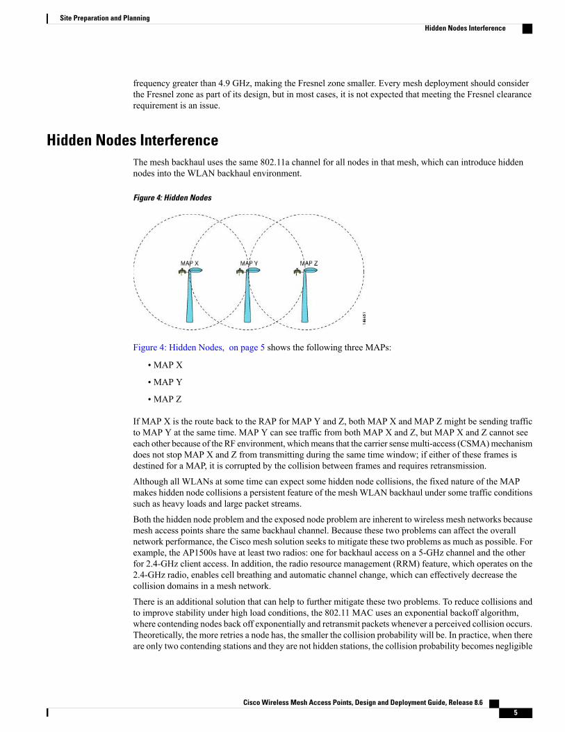
Hidden Nodes InterferenceThe mesh backhaul uses the same 802.11a channel for all nodes in that mesh, which can introduce hiddennodes into the WLAN backhaul environment.
Figure 4: Hidden Nodes
Figure 4: Hidden Nodes, on page 5 shows the following three MAPs:
• MAP X
• MAP Y
• MAP Z
If MAP X is the route back to the RAP for MAP Y and Z, both MAP X and MAP Z might be sending trafficto MAP Y at the same time. MAP Y can see traffic from both MAP X and Z, but MAP X and Z cannot seeeach other because of the RF environment, whichmeans that the carrier sensemulti-access (CSMA)mechanismdoes not stop MAP X and Z from transmitting during the same time window; if either of these frames isdestined for a MAP, it is corrupted by the collision between frames and requires retransmission.
Although all WLANs at some time can expect some hidden node collisions, the fixed nature of the MAPmakes hidden node collisions a persistent feature of the mesh WLAN backhaul under some traffic conditionssuch as heavy loads and large packet streams.
Both the hidden node problem and the exposed node problem are inherent to wireless mesh networks becausemesh access points share the same backhaul channel. Because these two problems can affect the overallnetwork performance, the Cisco mesh solution seeks to mitigate these two problems as much as possible. Forexample, the AP1500s have at least two radios: one for backhaul access on a 5-GHz channel and the otherfor 2.4-GHz client access. In addition, the radio resource management (RRM) feature, which operates on the2.4-GHz radio, enables cell breathing and automatic channel change, which can effectively decrease thecollision domains in a mesh network.
There is an additional solution that can help to further mitigate these two problems. To reduce collisions andto improve stability under high load conditions, the 802.11 MAC uses an exponential backoff algorithm,where contending nodes back off exponentially and retransmit packets whenever a perceived collision occurs.Theoretically, the more retries a node has, the smaller the collision probability will be. In practice, when thereare only two contending stations and they are not hidden stations, the collision probability becomes negligible
Cisco Wireless Mesh Access Points, Design and Deployment Guide, Release 8.6 5
Site Preparation and PlanningHidden Nodes Interference

after just three retries. The collision probability increases when there are more contending stations. Therefore,when there are many contending stations in the same collision domain, a higher retry limit and a largermaximum contention window are necessary. Further, collision probability does not decrease exponentiallywhen there are hidden nodes in the network. In this case, an RTS/CTS exchange can be used to mitigate thehidden node problem.
Preferred Parent SelectionYou can configure a preferred parent for a MAP. This feature gives more control to you and enables you toenforce a linear topology in a mesh environment. You can skip AWPP and force a parent to go to a preferredparent.
Preferred Parent Selection CriteriaThe child AP selects the preferred parent based on the following criteria:
• The preferred parent is the best parent.
• The preferred parent has a link SNR of at least 20 dB (other parents, however good, are ignored).
• The preferred parent has a link SNR in the range of 12 dB and 20 dB, but no other parent is significantlybetter (that is, the SNR is more than 20 percent better). For an SNR lower than 12 dB, the configurationis ignored.
• The preferred parent is not blacklisted.
• The preferred parent is not in silent mode because of dynamic frequency selection (DFS).
• The preferred parent is in the same bridge group name (BGN). If the configured preferred parent is notin the same BGN and no other parent is available, the child joins the parent AP using the default BGN.
Configuring a Preferred ParentTo configure a preferred parent, enter the following command:
(Cisco Controller) > config mesh parent preferred AP_name MAC
where:
• AP_name is the name of the child AP that you have to specify.
• MAC is the MAC address of the preferred parent that you have to specify.
When you configure a preferred parent, ensure that you specify the MAC address of theactual mesh neighbor for the desired parent. This MAC address is the base radio MACaddress that has the letter f as the final character. For example, if the base radio MACaddress is 00:24:13:0f:92:00, then you must specify 00:24:13:0f:92:0f as the preferredparent. This is the actual MAC address that is used for mesh neighbor relationships.
Note
Cisco Wireless Mesh Access Points, Design and Deployment Guide, Release 8.66
Site Preparation and PlanningPreferred Parent Selection

The following example shows how to configure the preferred parent for the MAP1SB access point, where00:24:13:0f:92:00 is the preferred parent’s MAC address:
(Cisco Controller) > config mesh parent preferred MAP1SB 00:24:13:0f:92:0fTo configure a preferred parent using the controller GUI, follow these steps:
1 ChooseWireless > Access Points > AP_NAME >Mesh.
2 Enter the MAC address of the preferred parent in the Preferred Parent text box.
To clear the Preferred Parent value, enter none in the Preferred Parent Text box.Note
3 Click Apply.
When the preferred parent is entered, no other mesh configurations can be made at the same time. Youmust apply the changes and wait for 90 seconds before other mesh changes can be made.
Note
Related CommandsThe following commands are related to preferred parent selection:
• To clear a configured parent, enter the following command:
(Cisco Controller) > config mesh parent preferred AP_name none
• To get information about the AP that is configured as the preferred parent of a child AP, enter thefollowing command:
(Cisco Controller) > show ap config general AP_name
The following example shows how to get the configuration information for the MAP1SB access point, where00:24:13:0f:92:00 is the MAC address of the preferred parent:
(Cisco Controller) > show ap config general MAP1
Cisco AP Identifier.............................. 9Cisco AP Name.................................... MAP1Country code..................................... US - United StatesRegulatory Domain allowed by Country............. 802.11bg:-A 802.11a:-AAP Country code.................................. US - United StatesAP Regulatory Domain............................. 802.11bg:-A 802.11a:-ASwitch Port Number .............................. 1MAC Address...................................... 12:12:12:12:12:12IP Address Configuration......................... DHCPIP Address....................................... 209.165.200.225IP NetMask....................................... 255.255.255.224CAPWAP Path MTU.................................. 1485Domain...........................................Name Server......................................Telnet State..................................... DisabledSsh State........................................ DisabledCisco AP Location................................ default location
Cisco Wireless Mesh Access Points, Design and Deployment Guide, Release 8.6 7
Site Preparation and PlanningPreferred Parent Selection

Cisco AP Group Name.............................. default-groupPrimary Cisco Switch Name........................ 4404Primary Cisco Switch IP Address.................. 209.165.200.230Secondary Cisco Switch Name......................Secondary Cisco Switch IP Address................ Not ConfiguredTertiary Cisco Switch Name....................... 4404Tertiary Cisco Switch IP Address................. 3.3.3.3Administrative State ............................ ADMIN_ENABLEDOperation State ................................. REGISTEREDMirroring Mode .................................. DisabledAP Mode ......................................... LocalPublic Safety ................................... Global: Disabled, Local: DisabledAP subMode ...................................... WIPSRemote AP Debug ................................. DisabledS/W Version .................................... 5.1.0.0Boot Version ................................... 12.4.10.0Mini IOS Version ................................ 0.0.0.0Stats Reporting Period .......................... 180LED State........................................ EnabledPoE Pre-Standard Switch.......................... EnabledPoE Power Injector MAC Addr...................... DisabledPower Type/Mode.................................. PoE/Low Power (degraded mode)Number Of Slots.................................. 2AP Model......................................... AIR-LAP1252AG-A-K9IOS Version...................................... 12.4(10:0)Reset Button..................................... EnabledAP Serial Number................................. serial_numberAP Certificate Type.............................. Manufacture InstalledManagement Frame Protection Validation........... Enabled (Global MFP Disabled)AP User Mode..................................... CUSTOMIZEDAP username..................................... mariaAP Dot1x User Mode............................... Not ConfiguredAP Dot1x username............................... Not ConfiguredCisco AP system logging host..................... 255.255.255.255AP Up Time....................................... 4 days, 06 h 17 m 22 sAP LWAPP Up Time................................. 4 days, 06 h 15 m 00 sJoin Date and Time............................... Mon Mar 3 06:19:47 2008
Ethernet Port Duplex............................. AutoEthernet Port Speed.............................. AutoAP Link Latency.................................. EnabledCurrent Delay................................... 0 msMaximum Delay................................... 240 msMinimum Delay................................... 0 msLast updated (based on AP Up Time).............. 4 days, 06 h 17 m 20 sRogue Detection.................................. EnabledAP TCP MSS Adjust................................ DisabledMesh preferred parent............................ 00:24:13:0f:92:00
Co-Channel InterferenceIn addition to hidden node interference, co-channel interference can also impact performance. Co-channelinterference occurs when adjacent radios on the same channel interfere with the performance of the local meshnetwork. This interference takes the form of collisions or excessive deferrals by CSMA. In both cases,performance of the mesh network is degraded.With appropriate channel management, co-channel interferenceon the wireless mesh network can be minimized.
Wireless Mesh Network Coverage ConsiderationsThis section provides a summary of items that must be considered for maximum wireless LAN coverage inan urban or suburban area, to adhere to compliance conditions for respective domains.
The following recommendations assume a flat terrain with no obstacles (green field deployment).
Cisco Wireless Mesh Access Points, Design and Deployment Guide, Release 8.68
Site Preparation and PlanningCo-Channel Interference

We always recommend that you perform a site survey before taking any real estimations for the area andcreating a bill of materials.
Cell Planning and Distance
For the Cisco 1500 Series Access Points
The RAP-to-MAP ratio is the starting point. For general planning purposes, the current ratio is 20 MAPs perRAP.
We recommend the following values for cell planning and distance in nonvoice networks:
• RAP-to-MAP ratio—Recommended maximum ratio is 20 MAPs per RAP.
• AP-to-AP distance—A spacing of no more than of 2000 feet (609.6 meters) between each mesh accesspoint is recommended. When you extend the mesh network on the backhaul (no client access), use acell radius of 1000 feet (304.8 meters).
• Hop count—Three to four hops.
◦One square mile in feet (52802), is nine cells and you can cover one square mile with approximatelythree or four hops (see Figure 5: Cell Radius of 1000 Feet and Access Point Placement for NonvoiceMesh Networks, on page 10 and Figure 6: Path Loss Exponent 2.3 to 2.7, on page 10.)
• For 2.4 GHz, the local access cell size radius is 600 feet (182.88 meters). One cell size is around 1.310x 10⁶, so there are 25 cells per square mile. (See Figure 7: Cell Radius of 600 Feet and Access Point
Cisco Wireless Mesh Access Points, Design and Deployment Guide, Release 8.6 9
Site Preparation and PlanningCell Planning and Distance

Placement for Nonvoice Mesh Networks, on page 10 and Figure 8: Path Loss Exponent 2.5 to 3.0, onpage 11.)
Figure 5: Cell Radius of 1000 Feet and Access Point Placement for Nonvoice Mesh Networks
Figure 6: Path Loss Exponent 2.3 to 2.7
Figure 7: Cell Radius of 600 Feet and Access Point Placement for Nonvoice Mesh Networks
Cisco Wireless Mesh Access Points, Design and Deployment Guide, Release 8.610
Site Preparation and PlanningCell Planning and Distance

Figure 8: Path Loss Exponent 2.5 to 3.0
For the Cisco 1550 Series Access Points
As seen in the previous section, we recommend a cell radius of 600 feet, and an AP to AP distance of 1200feet. Normally, an AP to AP distance that is twice the AP to client distance is recommended. That is, if wehalve the AP to AP distance, we will get the approximate cell radius.
Cisco Wireless Mesh Access Points, Design and Deployment Guide, Release 8.6 11
Site Preparation and PlanningCell Planning and Distance
The AP1500 series offers comparatively better range and capacity as it has the 802.11n functionality. It hasadvantages of ClientLink (Beamforming) in downstream, better receiver sensitivities because of MRC inupstream, multiple transmitter streams and a few other advantages of 802.11n such as channel combining andso on. The 1552 access points can provide comparatively larger and higher capacity cells.
Link budgets are different for different country domains. The discussion in this section takes into accountthe most widely distributed and large country domains: -A and -E.
Note
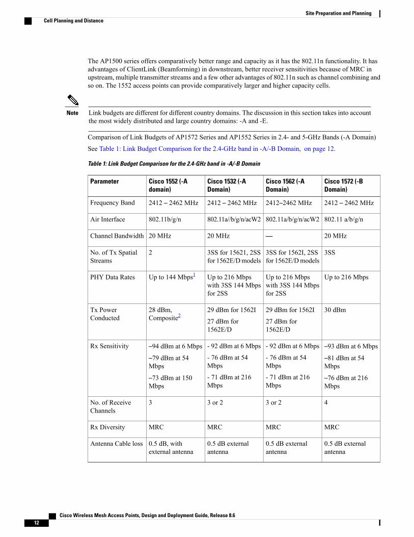
Comparison of Link Budgets of AP1572 Series and AP1552 Series in 2.4- and 5-GHz Bands (-A Domain)
See Table 1: Link Budget Comparison for the 2.4-GHz band in -A/-B Domain, on page 12.
Table 1: Link Budget Comparison for the 2.4-GHz band in -A/-B Domain
Cisco 1572 (-BDomain)
Cisco 1562 (-ADomain)
Cisco 1532 (-ADomain)
Cisco 1552 (-Adomain)
Parameter
2412 – 2462 MHz2412–2462 MHz2412 – 2462 MHz2412 – 2462 MHzFrequency Band
802.11 a/b/g/n802.11a/b/g/n/acW2802.11a//b/g/n/acW2802.11b/g/nAir Interface
20 MHz—20 MHz20 MHzChannel Bandwidth
3SS3SS for 1562I, 2SSfor 1562E/Dmodels
3SS for 15621, 2SSfor 1562E/Dmodels
2No. of Tx SpatialStreams
Up to 216 MbpsUp to 216 Mbpswith 3SS 144 Mbpsfor 2SS
Up to 216 Mbpswith 3SS 144 Mbpsfor 2SS
Up to 144 Mbps1PHY Data Rates
30 dBm29 dBm for 1562I
27 dBm for1562E/D
29 dBm for 1562I
27 dBm for1562E/D
28 dBm,Composite2
Tx PowerConducted
–93 dBm at 6 Mbps
–81 dBm at 54Mbps
–76 dBm at 216Mbps
- 92 dBm at 6 Mbps
- 76 dBm at 54Mbps
- 71 dBm at 216Mbps
- 92 dBm at 6 Mbps
- 76 dBm at 54Mbps
- 71 dBm at 216Mbps
–94 dBm at 6 Mbps
–79 dBm at 54Mbps
–73 dBm at 150Mbps
Rx Sensitivity
43 or 23 or 23No. of ReceiveChannels
MRCMRCMRCMRCRx Diversity
0.5 dB externalantenna
0.5 dB externalantenna
0.5 dB externalantenna
0.5 dB, withexternal antenna
Antenna Cable loss
Cisco Wireless Mesh Access Points, Design and Deployment Guide, Release 8.612
Site Preparation and PlanningCell Planning and Distance

1 40-MHz channel bonding in 2.4 GHz is not applicable. Therefore, the maximum data rate is 144 Mbps.2 Composite power is the power when we have two Tx streams enabled in AP1552.
For the 5-GHz band, see Table 2: Link Budget Comparison for the 5-GHz band in -A/-B Domain, on page13.
Table 2: Link Budget Comparison for the 5-GHz band in -A/-B Domain
Cisco 1572 (-BDomain)
Cisco 1562 (-A/BDomain)
Cisco 1532 (-ADomain)
Cisco 1552 (-ADomain)
Parameter
5.180 – 5.240 GHz5.260 – 5.320 GHz5.500 – 5.560 GHz5.680 – 5.720 GHz5.745 – 5.825 GHz
5.180 – 5.240 GHz5.260 – 5.320 GHz5.500 – 5.560 GHz5.680 – 5.720 GHz5.745 – 5.825 GHz
5.180 – 5.240 GHz5.260 – 5.320 GHz5.500 – 5.560 GHz5.680 – 5.720 GHz5.745 – 5.825 GHz
5745 – 5825 MHzFrequency Band
802.11a/n/ac802.11a/b/g/n/acW2802.11a/b/g/n/acW2802.11a/nAir Interface
20 MHz, 40 MHz,80 MHz
20 MHz, 40 MHz,80 MHz
20 MHz, 40 MHz,80 MHz
20 MHz, 40 MHzChannel Bandwidth
33 or 222No. of Tx SpatialStreams
Up to 1.3 Gbps1.300 / 867 MbpsUp to 300 MbpsUp to 300 MbpsPHY Data Rates
30 dBm29 or 27 dBm27 dBm28 dBm, CompositeTx PowerConducted
–92 dBm at 6 Mbps
–80 dBm at 54Mbps
–60 dBm at 1300Mbps
–94 dBm at 6 Mbps
–80 dBm at 54Mbps
–65 dBm at 1300Mbps
–94 dBm at 6 Mbps
–80 dBm at 54Mbps
–65 dBm at 1300Mbps
–92 dBm at 6 Mbps
–76 dBm at 54Mbps
–72 dBm at 300Mbps
Rx Sensitivity
The 20-MHz channel bonding to form a 40-MHz channel is available in 5 GHz. Therefore, we can go up toa data rate of 300 Mbps.
As discussed in the previous section, Path Loss Exponents (PLE) and Link Budget windows work together.For a full clear path, PLE is 2.0. For AP to AP, there is comparatively more clearance than AP to client. ForAP to AP, PLE can be taken as 2.3 because it can be assumed that the height of both APs is about 10 meters,which means a good line of sight (but without Fresnel zone clearance).
For AP to client, PLE should be greater than or equal to 2.5 because the client is only 1 meter high. Therefore,there will be less Fresnel zone clearance. This applies to both the 2.4-GHz and 5-GHz bands.
Let us consider AP to AP link budget in 5 GHz for -A domain because 5 GHz is used as a backhaul for mesh.We can take a legacy data rate of 9 Mbps to estimate the range.
Cisco Wireless Mesh Access Points, Design and Deployment Guide, Release 8.6 13
Site Preparation and PlanningCell Planning and Distance

This is the lowest data rate for outdoor 802.11n APs, which carries the Cisco's ClientLink (Beamformingfor Legacy clients) advantage. It provides a gain of up to 4 dB in the downlink direction.
Note
Assumptions for the Cisco Range Calculator• The Range Calculator has been edited to stay within limitations for Tx power and EIRP under the listedregulatory domains. There may be cases where it exceeds the limitations. You must verify that theinstallation is within the laws of the location in which it is being installed.
• All antenna ports must be used for external antenna models for effective performance. Otherwise, rangeis significantly compromised.
• The Tx power is the total composite power of both Tx paths.
• Rx sensitivity is the composite sensitivity of all three Rx paths. That is, MRC is included.
• The Range Calculator assumes that ClientLink (Beamforming) is switched on.
•When you use the Range Calculator, available power levels change based upon the regulatory domain,the antenna (or antenna gain) selected, and the data rate selected. You must verify all parameters aftermaking any parameter changes.
• You can select a different antenna than the two that are available by default. If you enter a high gainantenna and choose a power that goes over the EIRP limit, then you get a warning and the range equals0.
• You can choose only the channels that the access point is certified for.
• You can only select only valid power levels.
The RAPs shown in Figure 9: PoP with Multiple RAPs, on page 15 are simply a starting point. The goal isto use the RAP location in combination with the RF antenna design to ensure that there is a good RF link tothe MAP within the core of the cell, which means that the physical location of the RAPs can be on the edgeof the cell, and a directional antenna is used to establish a link into the center of the cell. Therefore, the wired
Cisco Wireless Mesh Access Points, Design and Deployment Guide, Release 8.614
Site Preparation and PlanningCell Planning and Distance
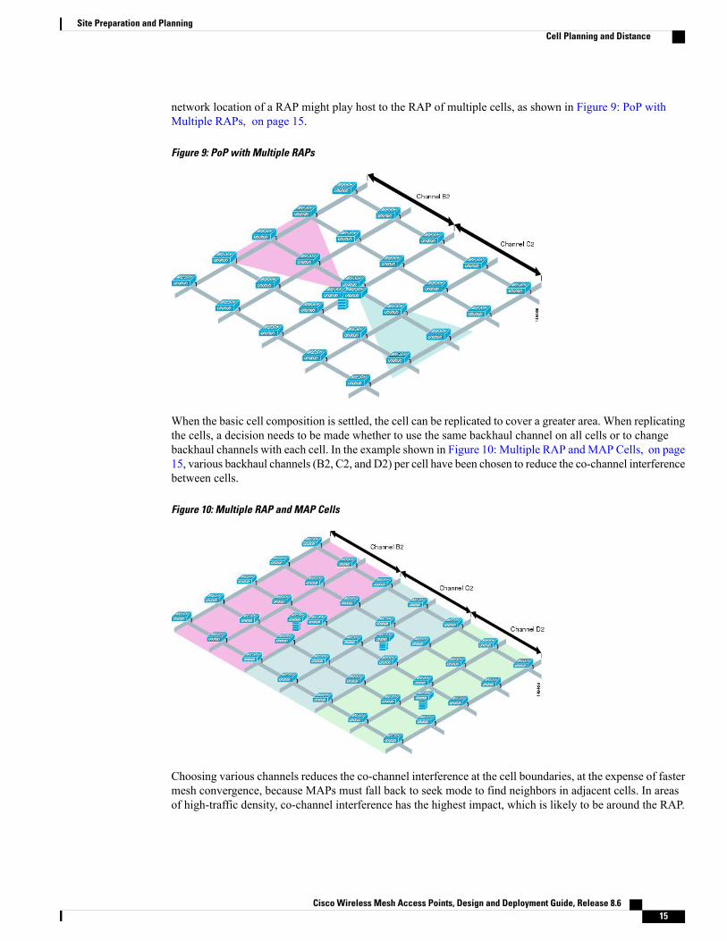
network location of a RAP might play host to the RAP of multiple cells, as shown in Figure 9: PoP withMultiple RAPs, on page 15.
Figure 9: PoP with Multiple RAPs
When the basic cell composition is settled, the cell can be replicated to cover a greater area. When replicatingthe cells, a decision needs to be made whether to use the same backhaul channel on all cells or to changebackhaul channels with each cell. In the example shown in Figure 10: Multiple RAP andMAP Cells, on page15, various backhaul channels (B2, C2, and D2) per cell have been chosen to reduce the co-channel interferencebetween cells.
Figure 10: Multiple RAP and MAP Cells
Choosing various channels reduces the co-channel interference at the cell boundaries, at the expense of fastermesh convergence, because MAPs must fall back to seek mode to find neighbors in adjacent cells. In areasof high-traffic density, co-channel interference has the highest impact, which is likely to be around the RAP.
Cisco Wireless Mesh Access Points, Design and Deployment Guide, Release 8.6 15
Site Preparation and PlanningCell Planning and Distance

If RAPs are clustered in one location, a different channel strategy is likely to give optimal performance; ifRAPs are dispersed among the cells, using the same channel is less likely to degrade performance.
When you lay out multiple cells, use channel planning similar to standardWLANplanning to avoid overlappingchannels, as shown in Figure 11: Laying out Various Cells, on page 16.
Figure 11: Laying out Various Cells
If possible, the channel planning should also minimize channel overlap in cases where the mesh has expandedto cover the loss of a RAP connection, as shown in Figure 12: Failover Coverage, on page 16.
Figure 12: Failover Coverage
Collocating Mesh Access PointsThe following recommendations provide guidelines to determine the required antenna separation when youcollocate AP1500s on the same tower. The recommendedminimum separations for antennas, transmit powers,and channel spacing are addressed.
The goal of proper spacing and antenna selection is to provide sufficient isolation by way of antenna radiationpattern, free space path loss, and adjacent or alternate adjacent channel receiver rejection to provide independentoperation of the collocated units. The goal is to have negligible throughput degradation due to a CCA hold-off,and negligible receive sensitivity degradation due to a receive noise floor increase.
Cisco Wireless Mesh Access Points, Design and Deployment Guide, Release 8.616
Site Preparation and PlanningCell Planning and Distance

You must follow antenna proximity requirements, which depend upon the adjacent and alternate adjacentchannel usage.
Collocating AP1500s on Adjacent Channels
If two collocated AP1500s operate on adjacent channels such as channel 149 (5745 MHz) and channel 152(5765 MHz), the minimum vertical separation between the two AP1500s is 40 feet (12.192 meters) (therequirement applies for mesh access points equipped with either 8 dBi omnidirectional or 17 dBi high-gaindirectional patch antennas).
If two collocated AP1500s operate on channels 1, 6, or 11 (2412 to 2437MHz) with a 5.5-dBi omnidirectionalantenna, then the minimum vertical separation is 8 feet (2.438 meters).
Collocating AP1500s on Alternate Adjacent Channels
If two collocated AP1500s operate on alternate adjacent channels such as channel 149 (5745MHz) and channel157 (5785 MHz), the minimum vertical separation between the two AP1500s is 10 feet (3.048 meters) (therequirements applies for mesh access points equipped with either 8-dBi omnidirectional or 17-dBi high-gaindirectional patch antennas).
If two collocated AP1500s operate on alternate adjacent channels 1 and 11 (2412 MHz and 2462 MHz) witha 5.5-dBi omnidirectional antenna, then the minimum vertical separation is 2 feet (0.609 meters).
In summary, a 5-GHz antenna isolation determines mesh access point spacing requirements and antennaproximity must be followed and is dependent upon the adjacent and alternate adjacent channel usage.
Special Considerations for Indoor Mesh NetworksNote these considerations for indoor mesh networks:
• For outdoors, voice is supported on a best-effort basis on a mesh infrastructure.
• Quality of Service (QoS) is supported on the local 2.4-GHz client access radio and on the 5-GHz.
• Cisco also supports static Call Admission Control (CAC) in CCXv4 clients, which provides CAC betweenthe access point and the client.
• RAP-to-MAP ratio—The recommended ratio is 3 to 4 MAPs per RAP.
• AP-to-AP distance:
◦For 11n and 11ac mesh APs, a spacing of no more than 250 feet between each mesh AP with acell radius of 125 feet is recommended.
• Hop count—For data, the maximum is 4 hops. No more than 2 hops is recommended for voice.
• RF considerations for client access on voice networks:
◦Coverage hole of 2 to 10 percent
◦Cell coverage overlap of 15 to 20 percent
◦Voice needs RSSI and SNR values that are at least 15 dB higher than data requirements
◦RSSI of -67 dBm for all data rates should be the goal for 11b/g/n and 11a/n
◦SNR should be 25 dB for the data rate used by client to connect to the AP
◦Packet error rate (PER) should be configured for a value of one percent or less
Cisco Wireless Mesh Access Points, Design and Deployment Guide, Release 8.6 17
Site Preparation and PlanningCell Planning and Distance

◦Channel with the lowest utilization (CU) must be usedCheck the CU when no traffic is running
◦Radio resource manager (RRM) can be used to implement the recommended RSSI, PER, SNR,CU, cell coverage, and coverage hole settings on the 802.11b/g/n/ac radio.
Figure 13: Cell Radius of 100 Feet (30.4 meters) and Access Point Placement for Voice Mesh Networks
Figure 14: Cell Radius of 125 Feet (38 meters) and Access Point Placement for Indoor 11n Mesh Networks
Although you can use directional antenna and have an AP-to-AP distance longer than250 feet (76.2 meters), for seamless roaming, we recommend that you have an AP-to-APdistance no more than 250 feet.
Note
Cisco Wireless Mesh Access Points, Design and Deployment Guide, Release 8.618
Site Preparation and PlanningCell Planning and Distance
Mesh AP Back-Ground Scan rel 8.3In release 8.3 additional enhancements introduced for faster mesh convergence - Mesh AP background scanfeature . There are already twoMesh convergence features implemented in releases 8.0 and 8.1WLC softwarereleases to reduce convergence time taken for a MAP and to re-converge the mesh network faster:
• Mesh Subset channel based convergence in rel 8.0
• Mesh Clear Channel Notification Convergence in rel 8.1
With both features in place, a 3rd Hop MAP in a mesh tree is able to re-converge and recover its data path inless than 10 seconds.
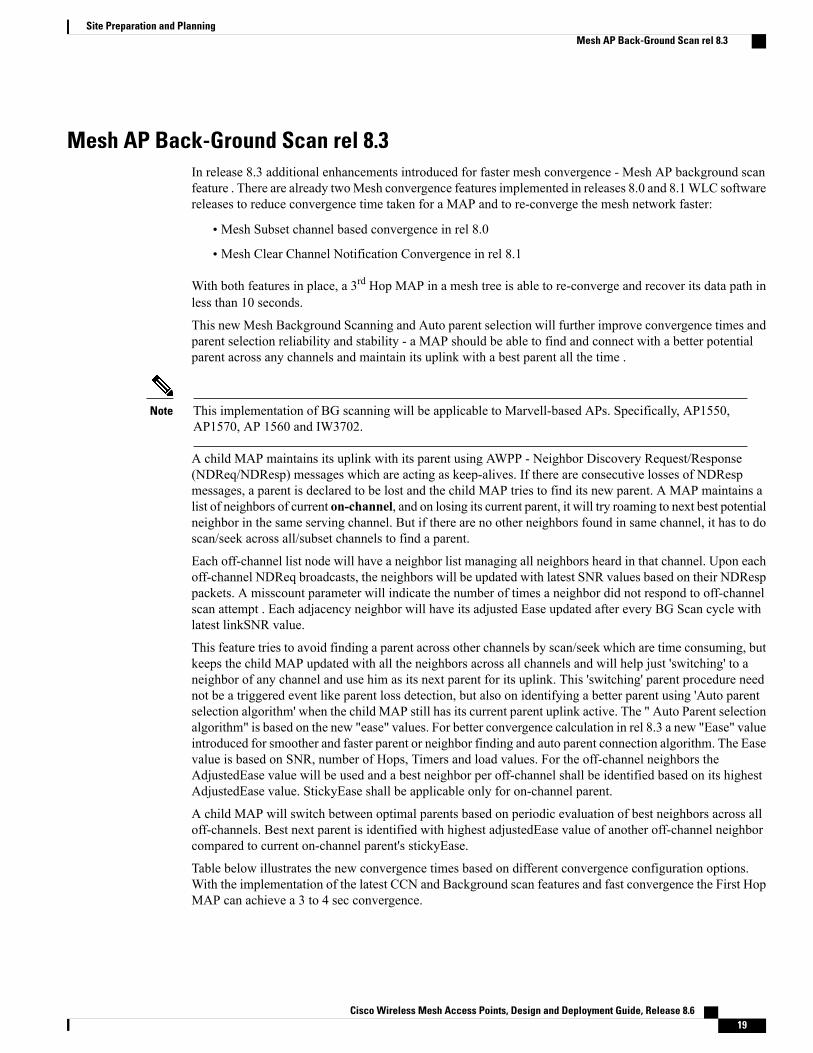
This new Mesh Background Scanning and Auto parent selection will further improve convergence times andparent selection reliability and stability - a MAP should be able to find and connect with a better potentialparent across any channels and maintain its uplink with a best parent all the time .
This implementation of BG scanning will be applicable to Marvell-based APs. Specifically, AP1550,AP1570, AP 1560 and IW3702.
Note
A child MAP maintains its uplink with its parent using AWPP - Neighbor Discovery Request/Response(NDReq/NDResp) messages which are acting as keep-alives. If there are consecutive losses of NDRespmessages, a parent is declared to be lost and the child MAP tries to find its new parent. A MAP maintains alist of neighbors of current on-channel, and on losing its current parent, it will try roaming to next best potentialneighbor in the same serving channel. But if there are no other neighbors found in same channel, it has to doscan/seek across all/subset channels to find a parent.
Each off-channel list node will have a neighbor list managing all neighbors heard in that channel. Upon eachoff-channel NDReq broadcasts, the neighbors will be updated with latest SNR values based on their NDResppackets. A misscount parameter will indicate the number of times a neighbor did not respond to off-channelscan attempt . Each adjacency neighbor will have its adjusted Ease updated after every BG Scan cycle withlatest linkSNR value.
This feature tries to avoid finding a parent across other channels by scan/seek which are time consuming, butkeeps the child MAP updated with all the neighbors across all channels and will help just 'switching' to aneighbor of any channel and use him as its next parent for its uplink. This 'switching' parent procedure neednot be a triggered event like parent loss detection, but also on identifying a better parent using 'Auto parentselection algorithm' when the child MAP still has its current parent uplink active. The " Auto Parent selectionalgorithm" is based on the new "ease" values. For better convergence calculation in rel 8.3 a new "Ease" valueintroduced for smoother and faster parent or neighbor finding and auto parent connection algorithm. The Easevalue is based on SNR, number of Hops, Timers and load values. For the off-channel neighbors theAdjustedEase value will be used and a best neighbor per off-channel shall be identified based on its highestAdjustedEase value. StickyEase shall be applicable only for on-channel parent.
A child MAP will switch between optimal parents based on periodic evaluation of best neighbors across alloff-channels. Best next parent is identified with highest adjustedEase value of another off-channel neighborcompared to current on-channel parent's stickyEase.
Table below illustrates the new convergence times based on different convergence configuration options.With the implementation of the latest CCN and Background scan features and fast convergence the First HopMAP can achieve a 3 to 4 sec convergence.
Cisco Wireless Mesh Access Points, Design and Deployment Guide, Release 8.6 19
Site Preparation and PlanningMesh AP Back-Ground Scan rel 8.3

Time per hop (sec)DHCP/CAPWAPInformation
Channel Scan/SeekParent LossDetection/ KeepAlive Timers
48.6*Renew / RestartCAPWAP
Scan/Seek all 2.4and 5 Ghz Channels
21 / 3 secStandard
20.5*MaintainDHCP andCAPWAP
Scan/Seek onlychannels found insame bridge group
7 / 3 secFast
15.9*MaintainDHCP andCAPWAP
Scan/Seek onlychannels found insame bridge group
4 / 1.5 secVery Fast
8-10 secMaintainDHCP andCAPWAP
Scan/Seek onlychannels found insame bridge group
4 / 3 sec for 50msCCN/BG ScanFast/VF
DFS and None-DFS Channel Scan
Non–DFS channel scan
• A MAP goes off-channel periodically, transmits NDReq broadcast packets on the selected off-channel,and shall receive NDResp packets from all ‘reachable’ neighbors
• Off-channel scan periodicity will occur every 3 seconds and stay for a maximum of 50 milliseconds peroff-channel
• NDReq has to be transmitted every 10 milliseconds to send at least 4 messages within 50 millisecondsdwell time to hear better from each neighbor
DFS channel scan
Per regulatory restrictions, an AP shall not transmit over a DFS channel (when set on radio for off-channelscan) unless the channel is declared to be 'safe to send'. If there are radar signals detected, there should be notransmission and the channel should be avoided for AP's wireless Tx/Rx. One way to make sure that thechannel is safe to send is by when the AP does passive scan and it receives any packet from other neighborswho are on DFS on-channel.
• To enableMAPs receive a packet during their off-channel scan over a DFS channel, all other on-channelDFS neighbors shall transmit the AWPP mesh beacons if there is no Tx/Rx in last 50 milliseconds
• These mesh beacons will help the MAPs which is doing the off-channel on the DFS channel to declare‘safe to send’ and do off-channel activities
Cisco Wireless Mesh Access Points, Design and Deployment Guide, Release 8.620
Site Preparation and PlanningMesh AP Back-Ground Scan rel 8.3
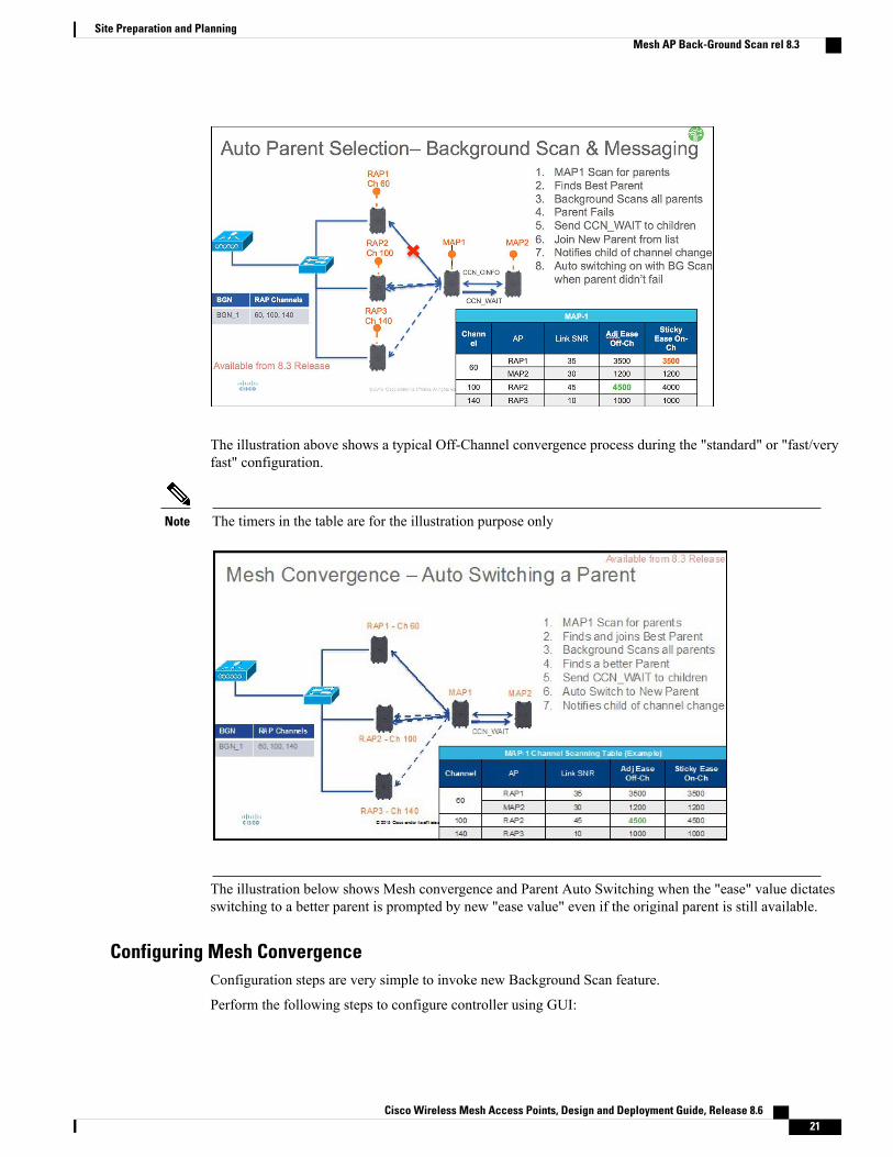
The illustration above shows a typical Off-Channel convergence process during the "standard" or "fast/veryfast" configuration.
The timers in the table are for the illustration purpose onlyNote
The illustration below shows Mesh convergence and Parent Auto Switching when the "ease" value dictatesswitching to a better parent is prompted by new "ease value" even if the original parent is still available.
Configuring Mesh ConvergenceConfiguration steps are very simple to invoke new Background Scan feature.
Perform the following steps to configure controller using GUI:
Cisco Wireless Mesh Access Points, Design and Deployment Guide, Release 8.6 21
Site Preparation and PlanningMesh AP Back-Ground Scan rel 8.3
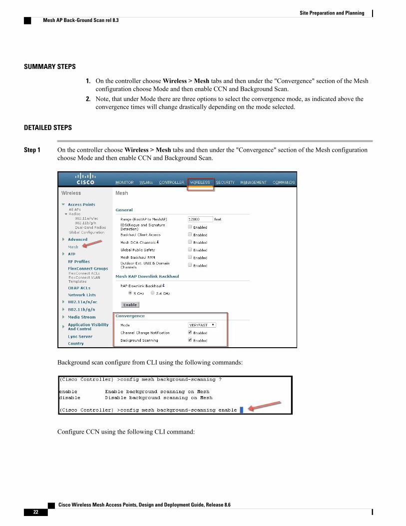
SUMMARY STEPS
1. On the controller chooseWireless > Mesh tabs and then under the "Convergence" section of the Meshconfiguration choose Mode and then enable CCN and Background Scan.
2. Note, that under Mode there are three options to select the convergence mode, as indicated above theconvergence times will change drastically depending on the mode selected.
DETAILED STEPS
Step 1 On the controller chooseWireless > Mesh tabs and then under the "Convergence" section of the Mesh configurationchoose Mode and then enable CCN and Background Scan.
Background scan configure from CLI using the following commands:
Configure CCN using the following CLI command:
Cisco Wireless Mesh Access Points, Design and Deployment Guide, Release 8.622
Site Preparation and PlanningMesh AP Back-Ground Scan rel 8.3

Step 2 Note, that under Mode there are three options to select the convergence mode, as indicated above the convergence timeswill change drastically depending on the mode selected.
From the CLI the same convergence configured using the following commands:
In Standardmode CCN and BG scan options do not applyNote
Managing Mesh Features
There are several commands introduced to debug and troubleshoot convergence issues
Debug mesh convergence enable—debug trace
Cisco Wireless Mesh Access Points, Design and Deployment Guide, Release 8.6 23
Site Preparation and PlanningMesh AP Back-Ground Scan rel 8.3

Debug mesh bgscan enable/disable
Show mesh convergence—for state and counters
Cisco Wireless Mesh Access Points, Design and Deployment Guide, Release 8.624
Site Preparation and PlanningMesh AP Back-Ground Scan rel 8.3

Show mesh bgscan
Cisco Wireless Mesh Access Points, Design and Deployment Guide, Release 8.6 25
Site Preparation and PlanningMesh AP Back-Ground Scan rel 8.3

Wireless Propagation CharacteristicsTable 3: Comparison of 2.4-GHz and 5-GHz Bands, on page 26 provides a comparison of the 2.4-GHz and5-GHz bands.
The 2.4-GHz band provides better propagation characteristics than 5 GHz, but 2.4 GHz is an unlicensed bandand has historically been affected with more noise and interference to date than the 5-GHz band. In addition,because there are only three backhaul channels in 2.4 GHz, co-channel interference would result. Therefore,the best method to achieve comparable capacity is by reducing system gain (that is, transmit power, antennagain, receive sensitivity, and path loss) to create smaller cells. These smaller cells require more access pointsper square mile (greater access point density).
Table 3: Comparison of 2.4-GHz and 5-GHz Bands
5-GHz Band Characteristics2.4-GHz Band Characteristics
22 channels (-A/-B regulatory domain)3 channels
No co-channel interferenceMore prone to co-channel interference
Higher powerLower power
Higher SNR requirements given higher data ratesLower SNR requirements given lower data rates
Worse propagation characteristics than 2.4 GHz butless susceptible to noise and interference
Better propagation characteristics than 5 GHz butmore susceptible to noise and interference
Not as widely available in the world as 2.4-GHz.Licenses in some countries.
Unlicensed band. Widely available throughout theworld.
Cisco Wireless Mesh Access Points, Design and Deployment Guide, Release 8.626
Site Preparation and PlanningWireless Propagation Characteristics
2.4 GHz has more penetration capability across the obstacles due to a larger wavelength. In addition, 2.4 GHzhas lower date rates which increases the success of the signal to reach the other end.
CleanAirThe 1550/1560/1570 series access points contain the CleanAir chipset, allowing full CleanAir support.
CleanAir in mesh can be implemented on the 2.4-GHz radio and provides clients complete 802.11n/ac datarates while detecting, locating, classifying, and mitigating radio frequency (RF) interference. This providesa carrier class management and customer experience and ensures that you have control over the spectrum inthe deployed location. CleanAir enabled RRM technology on the outdoor platform detects, quantifies, andmitigates Wi-Fi and non-Wi-Fi interference on 2.4-GHz radios. Access points operating in Bridge Modesupport CleanAir in 2.4 GHz client access mode.
CleanAir AP Modes of OperationBridge (Mesh) Mode AP—CleanAir capable access points offer complete CleanAir functionality in the 2.4GHz band and CleanAir advisor on the 5 GHz radio. This is across all access points that operate in Bridgemode.
Tight silicon integration with the Wi-Fi radio allows the CleanAir hardware to listen between traffic on thechannel that is currently being served with no penalty to throughput of attached clients. That is, line ratedetection without interrupting client traffic.
Bridge mode access points support Radio Resource Management (RRM) on the 2.4 GHz band, which helpsto mitigate the interference fromWiFi interferers. RRM is only available on the 5 GHz band, if a Bridge modeRAP has no child MAPs.
A CleanAir Mesh AP only scans one channel of each band continuously. In a normal deployment density,there should be many access points on the same channel, and at least one on each channel, assuming RRM ishandling channel selection. In 2.4 GHz, access points have sufficient density to ensure at least three points ofclassification. An interference source that uses narrow band modulation (operates on or around a singlefrequency) is only detected by access points that share the frequency space. If the interference is a frequencyhopping type (uses multiple frequencies—generally covering the whole band), it is detected by every accesspoint that can hear it operating in the band.
Monitor Mode AP (MMAP)—A CleanAir monitor mode AP is dedicated and does not serve client traffic.The monitor mode ensures that all bands-channels are routinely scanned. The monitor mode is not availablefor access points in bridge (mesh) mode because in a mesh environment, access points also talk to each otheron the backhaul. If a mesh AP (MAP) is in the monitor mode, then it cannot perform mesh operation.
Local Mode AP—When an outdoor access point is operating in local mode, it can preform full CleanAir andRRM on both the 2.4 GHz and 5 GHz channels. It will predominately scan its primary channel, but willperiodically go off-channel to scan the rest of the spectrum. Enhanced Local Mode (ELM) wIPS detection isnot available on the 1532, 1550, or 1570.
Spectrum Expert Connect Mode (optional) (SE Connect)—An SE Connect AP is configured as a dedicatedspectrum sensor that allows connection of the Cisco Spectrum Expert application running on a local host touse the CleanAir AP as a remote spectrum sensor for the local application. This mode allows viewing of theraw spectrum data such as FFT plots and detailed measurements. This mode is intended for only remotetroubleshooting.
Cisco Wireless Mesh Access Points, Design and Deployment Guide, Release 8.6 27
Site Preparation and PlanningCleanAir

Pseudo MAC (PMAC) and MergingPMAC andMerging phenomenon is similar to the one for Generation 2 access points in local mode. A PMACis calculated as part of the device classification and included in the interference device record (IDR). EachAP generates the PMAC independently. While it is not identical for each report (at a minimum the measuredRSSI of the device is likely different at each AP), it is similar. The function of comparing and evaluatingPMACs is called merging. The PMAC is not exposed to customer interfaces. Only the results of merging areavailable in the form of a cluster ID.
The same device can be detected by multiple APs. All the PMACs and IDRs are analyzed on the controllerand a report is generated called a device cluster, which shows the APs detecting the device and the devicecluster showing the AP which is hearing the device as strongest.
In this merging spatial proximity, RF proximity (RF neighbor relationship) work together. If there are sixsimilar IDRs with 5 APs nearby and another one from an AP that is far away, it is unlikely that it is the sameinterferer. Therefore, a cluster is formed taking all these into account. MSE and the controller first rely on RFNeighbor lists to establish spatial proximity in a merge.
PMAC Convergence and Merging depends upon the following factors:
• Density of the sensors
• Quality of the observed classification
• RSSI from the interferer to the APs
• RF neighbor list at the APs
So RRM on 2.4 GHz in mesh also plays a key role in deciding the merging aspect. APs should be RF neighborsfor any possibility of Merging. RF Neighbor list is consulted and spatial relationships for IDRs are taken intoaccount for Merging.
Because there is no Monitor Mode in mesh, a single controller merging occurs on the controller. The resultof a controller merge is forwarded to the MSE (if present) along with all of the supporting IDRs.
Cisco Wireless Mesh Access Points, Design and Deployment Guide, Release 8.628
Site Preparation and PlanningCleanAir

For more than one WLC (possible in outdoor deployments), merging occurs on the MSE. MSE does moreadvanced merging and extracts location and historical information for interferers. No Location is performedon controller merged interferers. Location is done on the MSE.
Figure 15: Pseudo MAC Merging in Outdoors
After PMAC signature merging, you can identify which AP can hear the device, and which AP is the centerof a cluster. In the figure above, the values are relevant to the band selected. The label R on AP indicates thatthe AP is a RAP and the line between APs shows the mesh relationship.
Event Driven Radio Resource Management and Persistence Device AvoidanceThere are two key mitigation features that are present with CleanAir. Both rely directly on information thatcan only be gathered by CleanAir. Event Driven Radio Resource Management (EDRRM) and PersistenceDevice Avoidance (PDA). For mesh networks, they work exactly the same way as for nonmesh networks inthe 2.4-GHz band.
EDRRM and PDA are only available in a Greenfield installation and configured off by default.Note
CleanAir Access Point Deployment RecommendationsCleanAir is a passive technology that does not affect the normal operation of Wi-Fi networks. There is noinherent difference between a CleanAir deployment and a mesh deployment.
Cisco Wireless Mesh Access Points, Design and Deployment Guide, Release 8.6 29
Site Preparation and PlanningCleanAir

Locating a non-Wi-Fi device has a lot of variables to consider. Accuracy increases with power, duty cycle,and the number of channels hearing the device. This is advantageous because higher power, higher duty cycle,and devices that impact multiple channels are considered to be severe with respect to interference to networks.
There is no guarantee of accuracy for location of non- Wi-Fi devices.Note
There are a lot of variables in the world of consumer electronics and unintentional electrical interference. Anyexpectation of accuracy that is derived from current Client or Tag location accuracy models does not applyto non-Wi-Fi location and CleanAir features.
Important notes to consider:
• CleanAir mesh AP supports the assigned channel only.
• Band Coverage is implemented by ensuring that channels are covered.
• The CleanAir mesh AP can hear very well, and the active cell boundary is not the limit.
• For Location solutions, the RSSI cutoff value is –75 dBm.
• A minimum of three quality measurements is required for location resolution.
In most deployments, it is difficult to have a coverage area that does not have at least three APs nearby onthe same channel in the 2.4-GHz band. In locations where there is minimal density, while the location resolutionis likely not supported, the active user channel is protected.
Deployment considerations are dependent upon planning the network for desired capacity and ensuring thatyou have the correct components and network paths in place to support CleanAir functions. RF proximityand the importance of RF Neighbor Relations cannot be understated. It is important to keep in mind the PMACand the merging process. If a network does not have a good RF design, the neighbor relations is affected,which in turn affects CleanAir performance.
The AP Density recommendations for CleanAir remain the same as normal mesh AP deployment.
Location resolution in the Outdoors is to the nearest AP. Devices are located near the AP which is physicallyclosest to the device. It is advisable to assume closest AP resolution.
It is possible to deploy a few 1530 APs (non-CleanAir) with an installation that consists of 1552 APs and1572 APs (CleanAir). This deployment can work from a client and coverage standpoint as these access pointsare fully interoperable with each other. The complete CleanAir functionality depends on all access pointsbeing CleanAir enabled. Detection can be affected, and mitigation is not recommended.
A CleanAir AP actively serving clients can only monitor the assigned channel that it is serving. In an areawhere you havemultiple access points serving clients in close proximity, the channels being served by CleanAiraccess points can drive CleanAir features. Legacy non-CleanAir access points rely on RRM, and mitigateinterference issues, but not report the type and severity as CleanAir access points do to the system level.
For more information about mixed systems, see http://www.cisco.com/en/US/products/ps10315/products_tech_note09186a0080b4bdc1.shtml
CleanAir AdvisorIf CleanAir is enabled on a backhaul radio, CleanAir Advisor is activated. CleanAir Advisor generates AirQuality Index (AQI) and Interferer Detection Reports (IDR) but the reports are only displayed in the controller.No action is taken through event driven RRM (ED-RRM). CleanAir Advisor is only present on the 5-GHz
Cisco Wireless Mesh Access Points, Design and Deployment Guide, Release 8.630
Site Preparation and PlanningCleanAir

backhaul radio of the 1552 access points in Bridge mode. In all other AP modes, the 5-GHz backhaul radioof the 1552 access points operates in CleanAir mode.
Enabling CleanAirTo enable CleanAir functionality in the system, you first need to enable CleanAir on the controller throughWireless > 802.11a/b > CleanAir. Although CleanAir is disabled by default, CleanAir is enabled by defaulton the AP interface.
After you enable CleanAir, it takes 15minutes to propagate air quality information because the default reportinginterval is 15 minutes. However, you can see the results instantly at the CleanAir detail level on the radio bygoing toMonitor > Access Points > 802.11a/n or 802.11b/n.
LicensingACleanAir system requires a CleanAir AP and a controller that is running release 7.0 or later releases. Addingthe Cisco Prime Infrastructure allows the displays to be enhanced and additional information to be correlatedwithin the system. Adding the MSE further enhances the available features and provides the history andlocation of specific interference devices. There is no additional license requirement for the CleanAir featurebecause the CleanAir AP is the license. Adding the Prime Infrastructure can be done with a basic license.Adding theMSE to the system requires a Prime Infrastructure Plus license and a context-aware license selectionfor the MSE.
For purposes of interference location with the MSE or CMX, each interference device counts as a locationtarget in Context-Aware. One hundred Permanent Interferer licenses are embedded in the MSE. InterfererLicenses open as CleanAir APs are detected, in stages of five licenses per CleanAir AP. This process isapplicable to AP1552/1562/1572. An Interference device is the same as a client or a tag from a license quantitystandpoint. Only a small percentage of the available licenses are used because there should be far lessinterference devices than clients or tags to track. Users do have control over what types of interference devicesto detect and located from the controller configuration menus.
Cisco context-aware licenses can be managed and limited by the class of target (client, tag, interference),which gives users complete control over how licenses are used.
Each interference device requires one context-aware service (CAS) license.Note
If you have too many Bluetooth devices, it is advisable to switch off the tracing of these devices because theymight take up too many CAS licenses.
Wireless Mesh Mobility GroupsA mobility group allows controllers to peer with each other to support seamless roaming across controllerboundaries. APs learn the IP addresses of the other members of the mobility group after the CAPWAP Joinprocess. A controller can be a member of a single mobility group which can contain up to 24 controllers.Mobility is supported across 72 controllers. There can be up to 72 members (WLCs) in the mobility list withup to 24 members in the same mobility group (or domain) participating in client hand-offs. The IP address ofa client does not have to be renewed in the same mobility domain. Renewing the IP address is irrelevant inthe controller-based architecture when you use this feature.
Cisco Wireless Mesh Access Points, Design and Deployment Guide, Release 8.6 31
Site Preparation and PlanningWireless Mesh Mobility Groups

Multiple ControllersThe consideration in distance of the CAPWAP controllers from other CAPWAP controllers in the mobilitygroup, and the distance of the CAPWAP controllers from the RAP, is similar to the consideration of anCAPWAP WLAN deployment in an enterprise.
There are operational advantages to centralizing CAPWAP controllers, and these advantages need to be tradedoff against the speed and capacity of the links to the CAPWAP APs and the traffic profile of the WLANclients using these mesh access points.
If the WLAN client traffic is expected to be focused on particular sites, such as the Internet or a data center,centralizing the controllers at the same sites as these traffic focal points gives the operational advantageswithout sacrificing traffic efficiency.
If the WLAN client traffic is more peer-to-peer, a distributed controller model might be a better fit. It is likelythat a majority of the WLAN traffic are clients in the area, with a smaller amount of traffic going to otherlocations. Given that many peer-to-peer applications can be sensitive to delay and packet loss, you shouldensure that traffic between peers takes the most efficient path.
Given that most deployments see a mix of client-server traffic and peer-to peer traffic, it is likely that a hybridmodel of CAPWAP controller placement is used, where points of presence (PoPs) are created with clustersof controllers placed in strategic locations in the network.
The CAPWAP model used in the wireless mesh network is designed for campus networks; that is, it expectsa high-speed, low-latency network between the CAPWAP mesh access points and the CAPWAP controller.
Increasing Mesh AvailabilityIn the Cell Planning Distance section, a wireless mesh cell of one square mile was created and then built upon.This wireless mesh cell has similar properties to the cells used to create a cellular phone network because thesmaller cells (rather than the defined maximum cell size) can be created to cover the same physical area,providing greater availability or capacity. This process is done by adding a RAP to the cell. Similar to thelarger mesh deployment, the decision is whether to use RAP on the same channel, as shown in Figure 16:Two RAPs per Cell with the Same Channel, on page 33, or to use RAPs placed on different channels, as
Cisco Wireless Mesh Access Points, Design and Deployment Guide, Release 8.632
Site Preparation and PlanningIncreasing Mesh Availability

shown in Figure 17: Two RAPs per Cell on Different Channels, on page 33. The addition of RAPs into anarea adds capacity and resilience to that area.
Figure 16: Two RAPs per Cell with the Same Channel
Figure 17: Two RAPs per Cell on Different Channels
Multiple RAPsIf multiple RAPs are to be deployed, the purpose for deploying these RAPs needs to be considered. If theRAPs are being deployed to provide hardware diversity, the additional RAP(s) should be deployed on thesame channel as the primary RAP to minimize the convergence time in a scenario where the mesh transfersfrom one RAP to another. When you plan RAP hardware diversity, consider the 32MAPs per RAP limitation.
Cisco Wireless Mesh Access Points, Design and Deployment Guide, Release 8.6 33
Site Preparation and PlanningIncreasing Mesh Availability

If additional RAPs are deployed to primarily provide additional capacity, then the additional RAPs should bedeployed on a different channel than its neighboring RAP to minimize the interference on the backhaulchannels.
Adding a second RAP on a different channel also reduces the collision domain through channel planning orthrough RAP cell splitting. Channel planning allocates different nonoverlapping channels to mesh nodes inthe same collision domain to minimize the collision probability. RAP cell splitting is a simple, yet effective,way to reduce the collision domain. Instead of deploying one RAP with omnidirectional antennas in a meshnetwork, two or more RAPs with directional antennas can be deployed. These RAPs collocate with each otherand operate on different frequency channels. This process divides a large collision domain into several smallerones that operate independently.
If the mesh access point bridging features are being used with multiple RAPs, these RAPs should all be onthe same subnet to ensure that a consistent subnet is provided for bridge clients.
If you build your mesh with multiple RAPs on different subnets, MAP convergence times increase if a MAPhas to fail over to another RAP on a different subnet. One way to limit this process from happening is to usedifferent BGNs for segments in your network that are separated by subnet boundaries.
Indoor Mesh Interoperability with Outdoor MeshComplete interoperability of indoor mesh access points with the outdoor ones is supported. It helps to bringcoverage from outdoors to indoors. We recommend indoor mesh access points for indoor use only, and theseaccess points should be deployed outdoors only under limited circumstances as described below.
The indoor access points in a third-party outdoor enclosure can be deployed for limited outdoordeployments, such as a simple short haul extension from an indoor WLAN to a hop in a parking lot. The1700, 1800, 2600, 2700, 2800, 3500e/i, 3600, 3700 and 3800 series access points in an outdoor enclosureis recommended because of its robust environmental and temperature specifications. Additionally, theindoor access points have connectors to support articulated antennas when the AP is within an outdoorenclosure. Exercise caution with the SNR values as they may not scale and long-term fades may take awaythe links for these APs when compared to a more optimized outdoor 1500 series access point.
Caution
Mobility groups can be shared between outdoor mesh networks and indoorWLAN networks. It is also possiblefor a single controller to control indoor and outdoor mesh access points simultaneously. The same WLANsare broadcast out of both indoor and outdoor mesh access points.
Cisco Wireless Mesh Access Points, Design and Deployment Guide, Release 8.634
Site Preparation and PlanningIndoor Mesh Interoperability with Outdoor Mesh