Embed Size (px)
Citation preview

«av
m SDMS Document
~A
64335
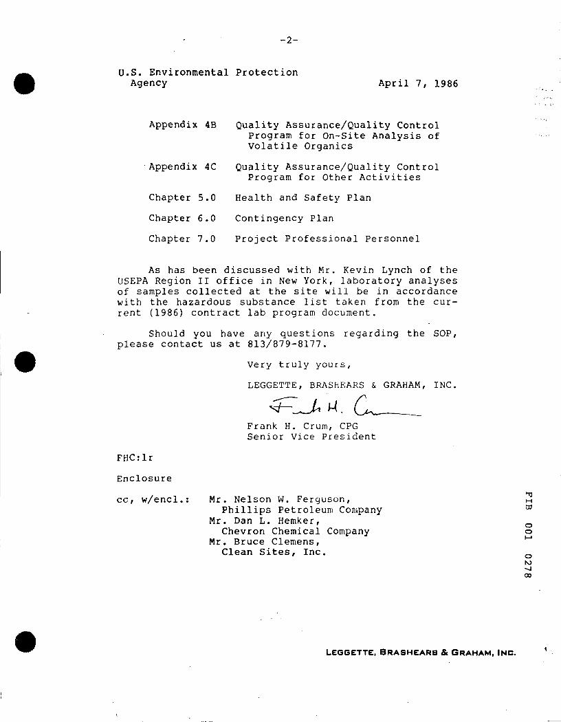
SITE OPERATIONS PLAN
REMEDIAL INVESTIGATION/FEASIBILITY STUDY
Fibers Public Supply Well Field
Quayama, Puerto Rico
Prepared by
LEGGETTE, BRASHEARS & GRAHAM, INC.
1211 North Westshore Boulevard
Tampa, Florida 33^07
APRIL, 1986 o o
o NJ
-17
-2-
U.S. Environmental Protection Agency April 7, 1986
Appendix 4B
Appendix 4C
Chapter 5.0
Chapter 6.0
Chapter 7.0
Quality Assurance/Quality Control Program for On-site Analysis of Volatile Organics
Quality Assurance/Quality Control Program for Other Activities
Health and Safety Plan
Contingency Plan
Project Professional Personnel
As has been discussed with Mr. Kevin Lynch of the USEPA Region II office in New York, laboratory analyses of samples collected at the site will be in accordance with the hazardous substance list taken from the current (1986) contract lab program document.
Should you have any questions regarding the SOP, please contact us at 813/879-8177.
Very truly yours,
LEGGETTE, BRASHEARS & GRAHAM, INC.
Frank H. Crum, CPG Senior Vice President
FHCrlr
Enclosure
cc, w/encl. Mr. Nelson W. Ferguson, Phillips Petroleum Company
Mr. Dan L. Hemker, Chevron Chemical Company
Mr. Bruce Clemens, Clean Sites, Inc.
M
o o
o K3
00
LEGGETTE, BRASHEARS & GRAHAM. INC.
SITE OPERATIONS PLAN
REMEDIAL INVESTIGATION/FEASIBILITY STUDY
Fibers Public Supply Well Field
Guayama, Puerto Rico
Prepared by
LEGGETTE. BRASHEARS & GRAHAM, INC.
1211 North Westshore Boulevard
Tampa, Florida 33607
APRIL, 1986 M DO
o o
o
I SITE OPERATIONS PLAN
REMEDIAL INVESTIGATION/FEASIBILITY STUDY
F ibers Public Supply Well F ie ld
Guayama, Puer to Rico
P repa red by
LEGGETTE, BRASHEARS & GRAHAM, INC.
1211 North Wes tsho re Bou leva rd
Tampa, Flor ida 3 3 6 0 7
APRIL, 1986
M 03
o o
o NJ 00 o
FIBERS PUBLIC SUPPLY WELL FIELD REMEDIAL INVESTIGATION/FEASIBILITY STUDY
GUAYAMA. PUERTO RICO
SITE OPERATIONS PLAN
TABLE OF CONTENTS
TITLE PAGE
CHAPTER 1.0 1.1 1.2
INTRODUCTION AND PROJECT ORGANIZATION PROJECT DESCRIPTION
PROJECT ORGANIZATION
1-1 1-1
CHAPTER 2.0 2.1 2.2 2.3 2.M 2.5 2.6 2.7 2.8 2.9 2.10 2.11 2.12 2.13 2.14
CHAPTER 3.0
CHAPTER 4.0
4.1
4.2 4.3 4.4
4.5 4.6
4.7 4.8
4.9 4.10 4.11
SITE ACTIVITIES GUIDE TOPOGRAPHIC MAPPING AND GROUND SURVEYING SURFACE GEOPHYSICAL SURVEYING SOIL-BORING ACTIVITIES MONITORING-WELL INSTALLATION HYDROLOGIC TESTING GROUND-WATER SAMPLING SURFACE-WATER SAMPLING SEDIMENT SAMPLING WATER-QUALITY ANALYSIS SOIL-QUALITY ANALYSIS GEOTECHNICAL TESTING AQUIFER TESTING COMPUTER MODELING DATA VALIDATION, EVALUATION AND RI
REPORT PREPARATION
SITE ACTIVITIES SCHEDULE
SITE SPECIFIC QUALITY ASSURANCE/QUALITY CONTROL DOCUMENT TITLE PAGE TABLE OF CONTENTS INTRODUCTION AND PROJECT DESCRIPTION PROJECT ORGANIZATION QUALITY ASSURANCE OBJECTIVES SAMPLING PROCEDURES SAMPLE CUSTODY
FIELD CALIBRATION PROCEDURES AND FREQUENCY ANALYTICAL PROCEDURES FIELD DATA ANALYSIS, VALIDATION AND REPORTING FIELD PERFORMANCE AND SYSTEM AUDITS
2-1 2-1
2-3 2-4 2-8 2-13 2-19 2-21 2-23 2-24 2-25 2-26
2-27 2-29
2-30
3-1
4-1 4-2
4-3 4-3 4-6 . 4-8 4-16 4-17 4-20 4-20 4-22
o o
o NJ CO
TABLE OF CONTENTS (CONTINUED)
TITLE PAGE
4.12 FIELD ANALYTICAL EQUIPMENT - PREVENTATIVE MAINTENANCE
4.13 SPECIFIC PROCEDURES TO ASSESS DATA PRECISION, ACCURACY AND COMPLETENESS
4.14 CORRECTIVE ACTION AND FEEDBACK 4.15 DOCUMENT CONTROL
APPENDIX 4-A LABORATORY QA PROJECT PLAN, FIBERS PUBLIC SUPPLY WELLS SITE
APPENDIX 4-B QUALITY ASSURANCE/QUALITY CONTROL PROGRAM FOR ON-SITE ANALYSES
APPENDIX 4-C QUALITY ASSURANCE/QUALITY CONTROL PROGRAM FOR OTHER ACTIVITIES
4-22
4-23 4-23 4-26
4-A-1
4-B-1
4-C-1
HEALTH AND SAFETY PLAN PROJECT DESCRIPTION ORGANIZATION AND RESPONSIBILITIES RISK ASSESSMENT AND PERSONAL PROTECTION EMERGENCY CONTACTS TRAINING
CONTINGENCY PLAN
CHAPTER 7.0 PROJECT PROFESSIONAL PERSONNEL
APPENDIX 7-A CURRICULUM VITAE OF PROJECT PROFESSIONALS
CHAPTER
CHAPTER
5.0 5.1 5.2 5.3 5.4 5.5
6.0
5-1 5-1 5-3 5-6 5-7 5-8
6-1
7-1
7-A-1
LIST OF FIGURES AND TABLES
CHAPTER 1
Figure 1.1-1 Figure 1.1-2 Figure 1.2-1
GENERALIZED SITE LOCATION MAP LOCATION OF SUPPLY WELLS PROJECT MANAGEMENT ORGANIZATION
1-2 1-3 1-5
Figure 2.1-1 Figure 2.3-1 Figure 2.4-1 Figure 2.4-2
CHAPTER 2
MEASURING-POINT LOCATION MAP SOIL BORING LOCATIONS MONITORING WELL LOCATIONS WATER-LEVEL CONTOUR MAP FEBRUARY, I986
2-2 2-6 2-10 2-11
H CO
o o
o NJ CO NJ

TABLE OF CONTENTS (CONTINUED)
TITLE PAGE
igure "igure "igure "igure
PERMEABILITY TESTING DATA COLLECTION FORM 2-15 EXAMPLE OF HOLD/WET WATER-LEVEL MEASURING METHOD 2-17 SURFACE-WATER DRAINAGE PATTERN 2-22 PUMP-TEST DATA FORM 2-28
Igure
CHAPTER 3
SITE ACTIVITIES SCHEDULE 3-2
CHAPTER 4
Igure "igure :able :able . "igure "igure 'igure "igure
GENERALIZED SITE LOCATION MAP PROJECT MANAGEMENT ORGANIZATION STANDARD SET OF BOTTLES FOR WATER SAMPLES STANDARD SET OF BOTTLES FOR SOIL SAMPLES SAMPLE IDENTIFICATION LABEL CHAIN-OF-CUSTODY RECORD CORRECTIVE ACTION SEQUENCE CORRECTIVE ACTION REQUEST FORM
ii-4 4-5 4-10 4-13 4-18 4-19 4-24 4-25
CHAPTER 5
Igure "igure
GENERALIZED SITE LOCATION MAP PROJECT MANAGEMENT ORGANIZATION
5-2 5-4
Table
CHAPTER 7
PROJECT PROFESSIONAL INVOLVEMENT 7-2
M DO
O o
o NJ 00
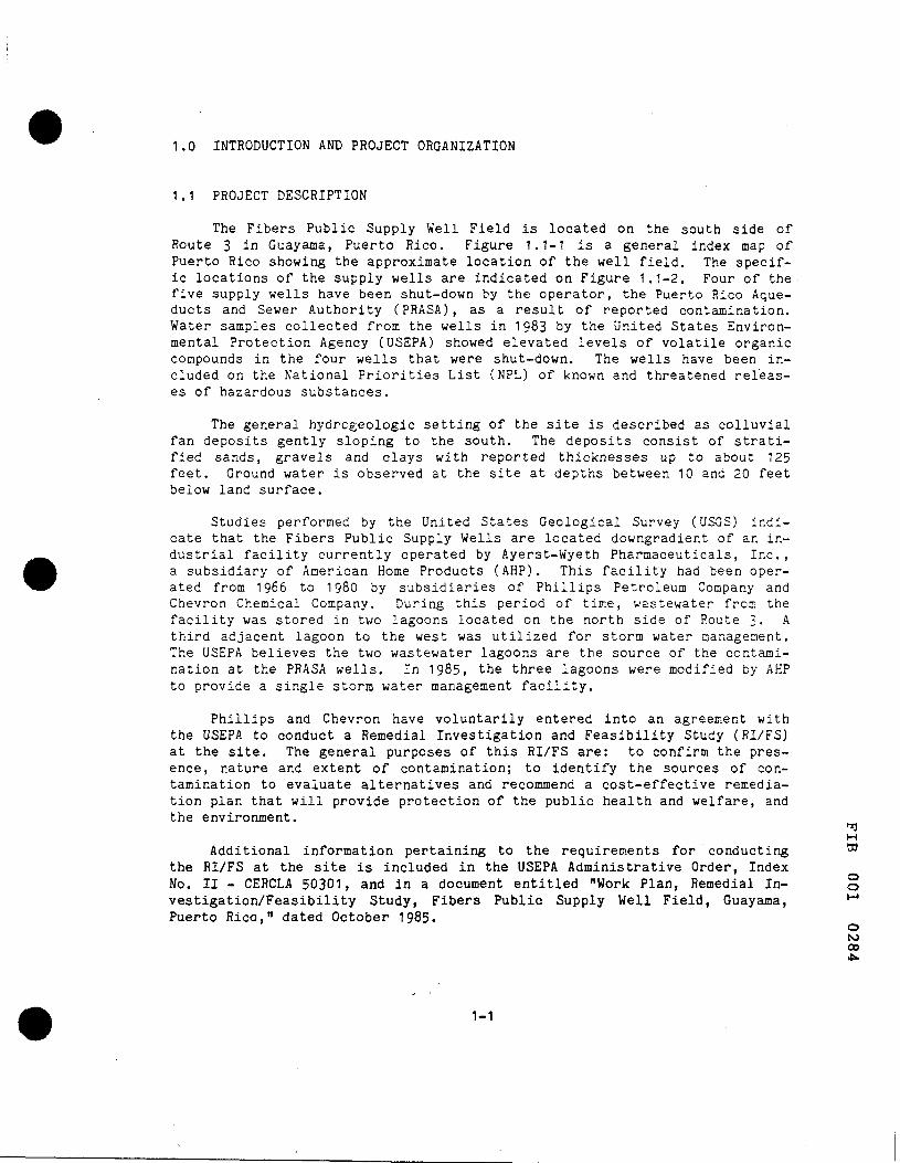
1.0 INTRODUCTION AND PROJECT ORGANIZATION
1.1 PROJECT DESCRIPTION
The Fibers Public Supply Well Field is located on the south side of Route 3 in Guayama, Puerto Rico. Figure 1.1-1 is a general index map of Puerto Rico showing the approximate location of the well field. The specific locations of the supply wells are indicated on Figure 1.1-2. Four of the five supply wells have been shut-down by the operator, the Puerto Rico Aqueducts and Sewer Authority (PRASA), as a result of reported contamination. Water samples collected from the wells in 1983 by the United States Environmental Protection Agency (USEPA) showed elevated levels of volatile organic compounds in the four wells that were shut-down. The wells have been included on the National Priorities List (NPL) of known and threatened releases of hazardous substances.
The general hydrogeologlc setting of the site is described as colluvial fan deposits gently sloping to the south. The deposits consist of stratified sands, gravels and clays with reported thicknesses up to about 125 feet. Ground water is observed at the site at depths between 10 and 20 feet below land surface.
Studies performed by the United States Geological Survey (USGS) indicate that the Fibers Public Supply Wells are located downgradient of an industrial facility currently operated by Ayerst-Wyeth Pharmaceuticals, Inc. , a subsidiary of American Home Products (AHP). This facility had been operated from 1966 to 1980 by subsidiaries of Phillips Petroleum Company and Chevron Chemical Company. During this period of time, wastewater from the facility was stored in two lagoons located on the north side of Route 3. A third adjacent lagoon to the west was utilized for storm water management. The USEPA believes the two wastewater lagoons are the source of the contamination at the PRASA wells. In 1985, the three lagoons were modified by AHP to provide a single storm water management facility.
Phillips and Chevron have voluntarily entered into an agreement with the USEPA to conduct a Remedial Investigation and Feasibility Study (RI/FS) at the site. The general purposes of this RI/FS are: to confirm the presence, nature and extent of contamination; to identify the sources of contamination to evaluate alternatives and recommend a cost-effective remediation plan that will provide protection of the public health and welfare, and the environment.
M Additional information pertaining to the requirem.ents for conducting ^
the RI/FS at the site is included in the USEPA Administrative Order, Index No. II - CERCLA 50301, and in a document entitled "Work Plan, Remedial In- ° vestigation/Feasibility Study, Fibers Public Supply Well Field, Guayama, ^ Puerto Rico," dated October 1985.
o NJ 00 4:
1-1

I ro
FIBERS PUBLIC SUPPLY WELL FIELD
RI/FS
GUAYAMA, PUERTO RICO
FIGURE 1.1-1 GENERALIZED SITE LOCATION MAP
ATLANTIC OCEAN SAN JUAN
PROJECT SITE
CARIBBEAN SEA < ^ SCALE
0 8 MILES
S820 TOO a i j

FIBERS PUBLIC SUPPLY WELL FIELD RI/FS
GUAYAMA. PUERTO RICO
FIGURE 1.1-2. LOCATION OF SUPPLY WELLS
. S FIBERS PUBLIC SUPPLY WELLS (PRASA) SCALE-FEET
2000
1-3
It is the purpose of this Site Operations Plan (SOP) to provide a detailed guide and schedule for the RI activities to be implemented at the site, to develop a Quality Assurance and Quality Control (QA/QC) methodology for these activities, and to establish a site-specific Health and Safety Plan (HSP).
Chapter 2, SITE ACTIVITIES GUIDE, describes the purpose of the activities, and provides a detailed list of equipment and procedures to accomplish each activity. Chapter 3, SITE ACTIVITIES SCHEDULE, outlines the anticipated schedule of the activities detailed in Chapter 2.
Chapter 4, SITE SPECIFIC QUALITY ASSURANCE/QUALITY CONTROL DOCUMENT, has been prepared as a stand-alone document as well as an integral part of the SOP. This chapter develops the QA/QC methodologies for the site activities and for the laboratory analyses.
Chapter 5, HEALTH AND SAFETY PLAN, has also been prepared as a standalone document as well as an integral portion of the SOP. This chapter provides the work-safety guidelines, requirements and procedures necessary to protect worker and public health from potential hazards related to the project activities. Chapter 5 will also be translated into Spanish prior to the commencement of site activities.
Chapter 6, CONTINGENCY PLAN, and Chapter 7, PROJECT PROFESSIONAL PERSONNEL, have 'been included to comply with the conditions of the Administrative Order.
1.2 PROJECT ORGANIZATION
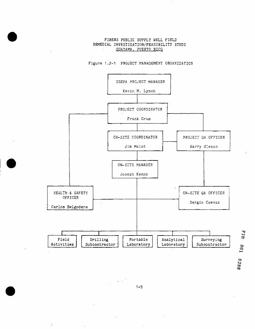
To provide a system of project task control as well as a definite command structure, an organization chart has been developed for the project. This project-management structure is shown in Figure 1.2-1.
1.2.1 COMMAND-STRUCTURE RESPONSIBILITIES
1.2.1.1 U.S. ENVIRONMENTAL PROTECTION AGENCY PROJECT MANAGER
The USEPA project manager will review the monthly progress reports, and act as a liaison between the project coordinator and the USEPA. The USEPA project manager will coordinate activities with the project coordinator. Mr. Kevin M. Lynch will be the USEPA project manager with Mr. Carlos E. "^ O'Neill being his designated on-site representative. ca
1.2.1.2 PROJECT COORDINATOR o o M
The project coordinator will have the overall responsibility for the project. An important function of the project coordinator will be to inter- o face between the USEPA project manager and the project team. All documents ^ transmitted to the USEPA from the project team will be reviewed and approved ^
1-4
FIBERS PUBLIC SUPPLY WELL FIELD REMEDIAL INVESTIGATION/FEASIBILITY STUDY
GUAYAMA, PUERTO RICO
Figure 1.2-1 PROJECT MANAGEMENT ORGANIZATION
HEALTH & SAFETY OFFICER
Carlos Belgodere
Field Activities
USEPA PROJECT MANAGER
Kevin M. Lynch
PROJECT COORDINATOR
Frank Crum
ON-SITE COORDINATOR
Jim Malot
ON-SITE MANAGER
Joseph Kenny
Drilling Subcontractor
Portable Laboratory
PROJECT QA OFFICER
Harry Oleson
ON-SITE QA OFFICER
Sergio Cuevas
Analytical Laboratory
Surveying Subcontractor
CO
o o
o NJ CO CO
1-5
by the project coordinator prior to submittal. Specific responsibilities of the project coordinator with respect to the QA/QC and health and safety (H/S) aspects of the project are described in Sections 4 and 5 of the SOP, respectively. Mr. Frank Crum of Leggette, Brashears & Graham, Inc. (LBG) is the project coordinator for this project.1.2.1.3 PROJECT QA OFFICER
The project QA officer is responsible for ensuring that the QA/QC procedures are followed by the project personnel and subcontractors. Specific to these responsibilities is the review of QA documentation from the field laboratory operated by the firm of James J. Malot, P.E. (JJM), the Environmental Testing and Certification Laboratory (ETC), Geotec, Inc. (drilling subcontractor), and Kelly Alvarez, BSLS (surveying subcontractor). The project QA officer will maintain a log of those documents reviewed and will provide this documentation to the project coordinator. Other responsibilities specific to the QA/QC methodologies are described in Chapter 4 of the SOP. Mr. Harry Oleson (LBG) is the designated project QA officer.
1.2.1.4 ON-SITE COORDINATOR
This management position lies directly below the project coordinator, and is responsible directly to Mr. Crum. Portions of the monthly progress reports will be prepared by the on-site coordinator in addition to the review of portions prepared by individuals for which he is responsible. Specific QA/QC and HSP responsibilities are described in Chapters 4 and 5, respectively. Mr. James Malot (JJM) is the designated on-site coordinator for the project.
1 .2.1 .5 ON-SITE MANAGER
The on-site manager will be responsible for the day-to-day management of field activities at the project site. Duties and responsibilities specific to the QA/QC and HSP aspects of the project are described in Chapters 4 and 5 of the SOP, respectively. The on-site manager is directly responsible to the on-site coordinator. Joseph Kenny (JJM) is the designated on-site manager.
1.2.1.6 ON-SITE QA OFFICER
The on-site QA officer's duties and responsibilities include the daily review and documentation of sample collection and field analyses. This position is responsible, in general matters, to the on-site manager and, in QA matters, to the project QA officer. Specific responsibilities regarding QA/QC aspects of the project are described in Chapter 4 of the SOP. Mr. Sergio Cuevas (JJM) is the designated on-site QA officer for the project. a
o o
o NJ 00
1-6
1.2.1.7 HEALTH AND SAFETY OFFICER
The health and safety (H/S) officer will be primarily responsible for the on-site adherence to the HSP guidelines described in Chapter 5 of the SOP. This position is directly responsible to the on-site manager. Mr. Carlos Belgodere (JJM) is the designated H/S officer for this project.
1.2.1.8 TASK MANAGERS
Task managers are those individuals who, during the course of the project, direct sampling, drilling, analytical or hydrologic testing activities. The task managers are directly responsible to the applicable offi-cer(s) described above and shown in Figure 1.2-1. The definition of task manager includes subcontractor representatives and field or crew chiefs when appropriate.
M 00
o o
o NJ
o
1-7
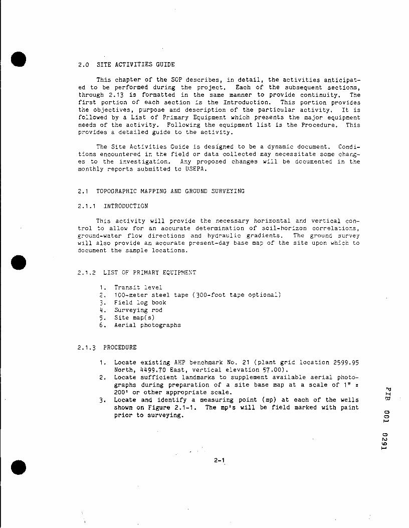
2.0 SITE ACTIVITIES GUIDE
This chapter of the SOP describes, in detail, the activities anticipated to be performed during the project. Each of the subsequent sections, through 2.13 is formatted in the same manner to provide continuity. The first portion of each section is the Introduction. This portion provides the objectives, purpose and description of the particular activity. It is followed by a List of Primary Equipment which presents the major equipment needs of the activity. Following the equipment list is the Procedure. This provides a detailed guide to the activity.
The Site Activities Guide is designed to be a dynamic document. Conditions encountered in the field or data collected may necessitate some changes to the investigation. Any proposed changes will be documented in the monthly reports submitted to USEPA.
2.1 TOPOGRAPHIC MAPPING AND GROUND SURVEYING
2.1.1 INTRODUCTION
This activity will provide the necessary horizontal and vertical control to allow for an accurate determination of soil-horizon correlations, ground-water flow directions and hydraulic gradients. The ground survey will also provide an accurate present-day base map of the site upon which to document the sample locations.
2.1.2 LIST OF PRIMARY EQUIPMENT
1 . Transit level 2. 100-meter steel tape (300-foot tape optional) 3. Field log book 4. Surveying rod 5. Site map(s) 6. Aerial photographs
2.1.3 PROCEDURE
1. Locate existing AHP benchmark No. 21 (plant grid location 2599-95 North, 4499.70 East, vertical elevation 57.00).
2. Locate sufficient landmarks to supplement available aerial photographs during preparation of a site base map at a scale of 1" = 200' or other appropriate scale. ^
DO Locate and identify a measuring point (mp) at each of the wells shown on Figure 2,1-1, The mp's will be field marked with paint prior to surveying. o
o
o NJ VO
2-1

FIBERS PUBLIC SUPPLY WELL FIELD RI/FS
GUAYAMA. PUERTO RICO
FIGURE 2.1-1 MEASURING POINT LOCATION MAP
® FIBERS PUBLIC SUPPLY WELLS (PRASA) SCALE-FEET
• INDUSTRIAL WELLS 2000
2-2
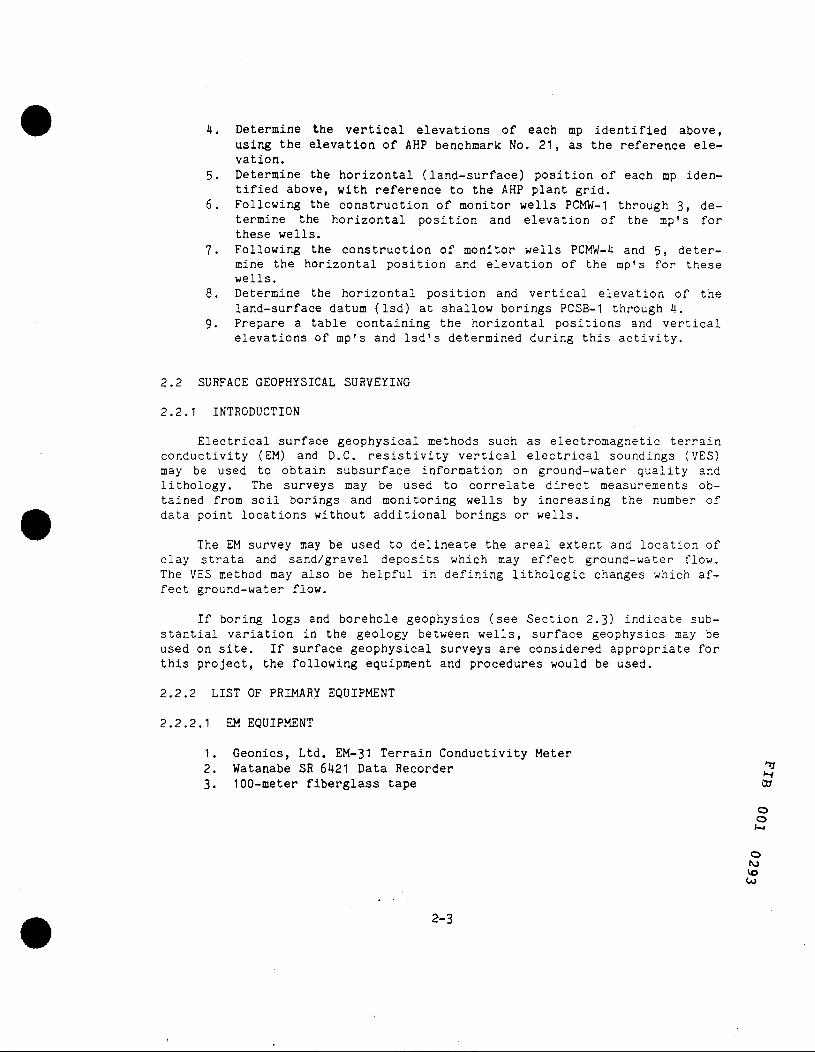
4. Determine the vertical elevations of each mp identified above, using the elevation of AHP benchmark No. 21, as the reference elevation.
5. Determine the horizontal (land-surface) position of each mp identified above, with reference to the AHP plant grid.
6. Following the construction of monitor wells PCMW-1 through 3, determine the horizontal position and elevation of the mp's for these wells.
7. Following the construction of monitor wells PCMW-4 and 5, determine the horizontal position and elevation of the mp's for these wells.
8. Determine the horizontal position and vertical elevation of the land-surface datum (Isd) at shallow borings PCSB-1 through 4.
9. Prepare a table containing the horizontal positions and vertical elevations of mp's and Isd's determined during this activity.
2.2 SURFACE GEOPHYSICAL SURVEYING
2.2.1 INTRODUCTION
Electrical surface geophysical methods such as electromagnetic terrain conductivity (EM) and D.C. resistivity vertical electrical soundings (VES) may be used to obtain subsurface information on ground-water quality and lithology. The surveys may be used to correlate direct measurements obtained from soil borings and monitoring wells by increasing the number of data point locations without additional borings or wells.
The EM survey may be used to delineate the areal extent and location of clay strata and sand/gravel deposits which may effect ground-water flow. The VES method may also be helpful in defining lithologic changes which affect ground-water flow.
If boring logs and borehole geophysics (see Section 2.3) indicate substantial variation in the geology between wells, surface geophysics may be used on site. If surface geophysical surveys are considered appropriate for this project, the following equipment and procedures would be used.
2.2.2 LIST OF PRIMARY EQUIPMENT
2.2.2.1 EM EQUIPMENT
1. Geonics, Ltd. EM-31 Terrain Conductivity Meter
2. Watanabe SR 6421 Data Recorder 3. 100-meter fiberglass tape to 2. Watanabe SR 6421 Data Recorder 3
o o
o NJ VO Co
2-3
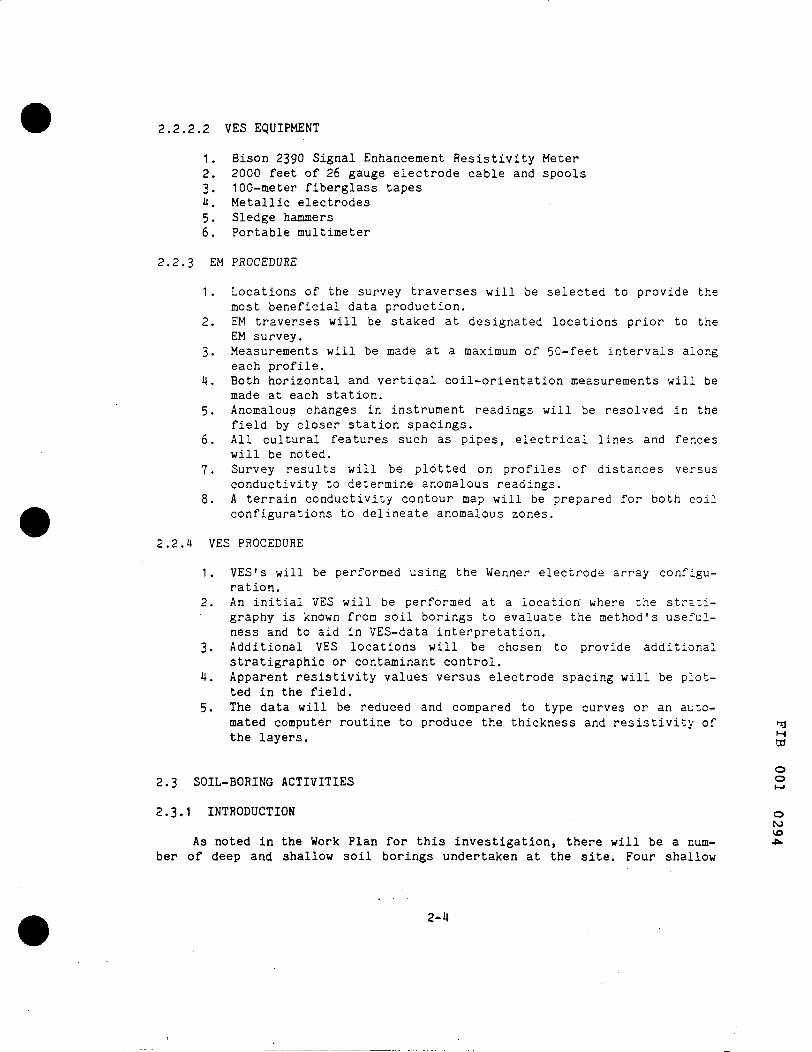
2.2,2.2 VES EQUIPMENT
1. Bison 2390 Signal Enhancement Resistivity Meter 2. 2000 feet of 26 gauge electrode cable and spools 3. 100-meter fiberglass tapes 4. Metallic electrodes 5. Sledge hammers 6. Portable multimeter
2.2.3 EM PROCEDURE
1 , Locations of the survey traverses will be selected to provide the most beneficial data production.
2. EM traverses will be staked at designated locations prior to the EM survey.
3. Measurements will be made at a maximum of 50-feet intervals along each profile.
4. Both horizontal and vertical coil-orientation measurements will be made at each station.
5. Anomalous changes in instrument readings will be resolved in the field by closer station spacings.
6. All cultural features such as pipes, electrical lines and fences will be noted.
7. Survey results will be plotted on profiles of distances versus conductivity to determine anomalous readings.
8. A terrain conductivity contour map will be prepared for both coil configurations to delineate anomalous zones.
2.2.4 VES PROCEDURE
1. VES's will be performed using the Wenner electrode array configuration.
2. An initial VES will be performed at a location where the stratigraphy is known from soil borings to evaluate the method's usefulness and to aid in VES-data interpretation,
3. Additional VES locations will be chosen to provide additional stratigraphic or contaminant control.
4. Apparent resistivity values versus electrode spacing will be plotted in the field,
5. The data will be reduced and compared to type curves or an automated computer routine to produce the thickness and resistivity of nj the layers. M
03
O
2.3 SOIL-BORING ACTIVITIES 2
2.3.1 INTRODUCTION o NJ VO
As noted in the Work Plan for this investigation, there will be a num- *» ber of deep and shallow soil borings undertaken at the site. Four shallow
2-4

borings (PCSB-1 through 4) will be drilled in the vicinity of the lagoons, and deep soil borings will be drilled at the site of each of the 5 proposed monitor wells (PCMW-1 through 5).
Locations of the four shallow borings around the lagoon (PCSB-1 through 4) have been selected based on the following objectives: 1.) To obtain soil samples in close proximity to the original wastewater lagoons, and 2.) To determine the vertical distribution of any contaminants in the vicinity of the lagoon area.
Three deep soil borings at the site of monitor wells PCMW-1 , 2 and 3 will be advanced to bedrock. The remaining 2 deep soil borings at PCMV,'-4 and 5 will be advanced to depths consistent with the screen locations selected for the first three monitoring wells. Thus, field data, including on-site soil stratigraphy, borehole geophysics and soil testing for VCC's will be used to select the depth of soil borings at PCMW-4 and 5.
The locations of these soil borings are shown on Figure 2.3-1. All samples collected during the drilling and sampling operations will be field inspected by a hydrogeologist to establish the site lithology. Health and safety guidelines (Chapter 5) will be followed during drilling and testing operations.
Soil samples will be analyzed in the field with a portable Gas Chromatograph (GC) to gather data on the extent of any soil contamination with respect to volatile organics. These data will be used to establish a vertical profile of soil contamination. The contaminant profile developed from field GC data will be used, along with the soil stratigraphy to select 1.) the screened intervals of monitoring wells, 2.) soil samples that will be sent to ETC for complete chemical analysis, 3.) correlation of potential contaminant migration pathways, and 4.) samples for geotechnical testing. Complete chemical analysis on selected samples will be performed. Selected samples will be sent to Geotec, Inc. (Geotec) for geotechnical testing.
Following the completion of the deep borings, the borehole will be filled with a bentonite slurry (drilling mud) to maintain an open hole. Geophysical logs will be run in these boreholes to provide additional data to select the screened intervals of the monitor wells (Section 2.4). After geophysical logging, each borehole will be abandoned by filling with grout. Both borehole fluids will be collected and stored in drums prior to disposal according to local regulations.
2.3.2 LIST OF PRIMARY EQUIPMENT ^
1. Drilling rig ™ 2. Six-inch diameter hollow-stem augers 3. Split-spoon barrels o 4. Clean pails •"" 5. l6-ounce wide mouth j a r s
o NJ VO
2-5

FIBERS PUBLIC SUPPLY WELL FIELD RI/FS
GUAYAMA. PUERTO RICO
FIGURE 2.3-1 SOIL BORING LOCATIONS
V DEEP BORING
A SHALLOW BORING
0 SOIL BORING- DEPTH TQ BE DETERMINED IN THE FIELD
SCALE-FEET
0 500
o N) VO
2-6
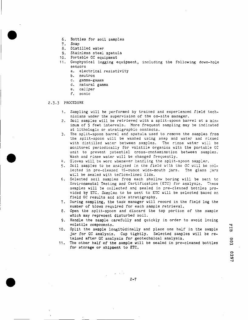
6. Bottles for soil samples 7. Soap 8. Distilled water 9. Stainless steel spatula 10. Portable GC equipment 11. Geophysical logging equipment, including the following down-hole
sensors a. electrical resistivity b. neutron c. gamma-gamma d. natural gamma e. caliper f. sonic
2.3.3 PROCEDURE
1. Sampling will be performed by trained and experienced field technicians under the supervision of the on-site manager.
2. Soil samples will be retrieved with a split-spoon barrel at a minimum of 5 feet intervals. More frequent sampling may be indicated at lithologic or stratigraphic contacts.
3. The split-spoon barrel and spatula used to remove the samples from the split-spoon will be washed using soap and water and rinsed with distilled water between samples. The rinse water will be monitored periodically for volatile organics with the portable GC unit to prevent potential cross-contamination between samples. Wash and rinse water will be changed frequently.
4. Gloves will be worn whenever handling the split-spoon sampler. 5. Soil samples to be analyzed in the field with the GC will be col
lected in pre-cleaned l6-ounce wide-mouth jars. The glass jars will be sealed with teflon-lined lids.
6. Selected soil samples from each shallow boring will be sent to Environmental Testing and Certification (ETC) for analysis. These samples will be collected and sealed in pre-cleaned bottles provided by ETC. Samples to be sent to ETC will be selected based on field GC results and site stratigraphy.
7. During sampling, the task manager will record in the field log the number of blows required for each sample retrieval.
8. Open the split-spoon and discard the top portion of the sample which may represent disturbed soil.
9. Handle the sample carefully and quickly in order to avoid losing volatile components. 'fl
10. Split the sample longitudinally and place one half in the sample ^ jar for GC analysis. Cap tightly. Selected samples will be retained after GC analysis for geotechnical analysis. o
11. The other half of the sample will be sealed in pre-cleaned bottles for storage or shipment to ETC.
o
o NJ vo -J
2-7
12. Complete and affix a sample tag to the jar. Record the information in the sampling log book. Complete and sign a chain-of-custody form before relinquishing the sample to the field laboratory for immediate analysis.
13. The water levels encountered during soil sampling and drilling will be recorded.
14. Descriptions of soil samples will be recorded by the hydrogeologist as the samples are collected. A detailed lithologic log will be developed in the field during drilling.
15. Samples will be tested in a field laboratory for volatile organic compounds using EPA Method No, 8020 from Test Methods for Evaluating Solid Waste (SW-846).
16. Samples for testing by ETC will be sent by express courier. 17. Selected duplicate samples will be taken by placing each half of a
longitudinally split core in suitable container and filling out two sample tags indicating a duplicate sample.
18. Field blanks are taken by rinsing a pre-cleaned split-spoon sampler with distilled water and placing the water in a clean glass jar. Initially, field blanks will be taken and analyzed every six samples. As the sampling activities progress, the frequency of sampling will be determined from statistical analysis of previous data.
19. The deep borings will be filled with a bentonite slurry to maintain hole integrity for geophysical logging. This will be done by installing a tremie pipe near the bottom of the hole and pumping the slurry while removing augers. Care will be taken to maintain a positive head on the borehole fluid to prevent collapse of the hole.
20. Geophysical logs will be run in the boreholes. The logs run may include electrical resistivity, neutron, gamma-gamma, natural gamma, caliper and sonic.
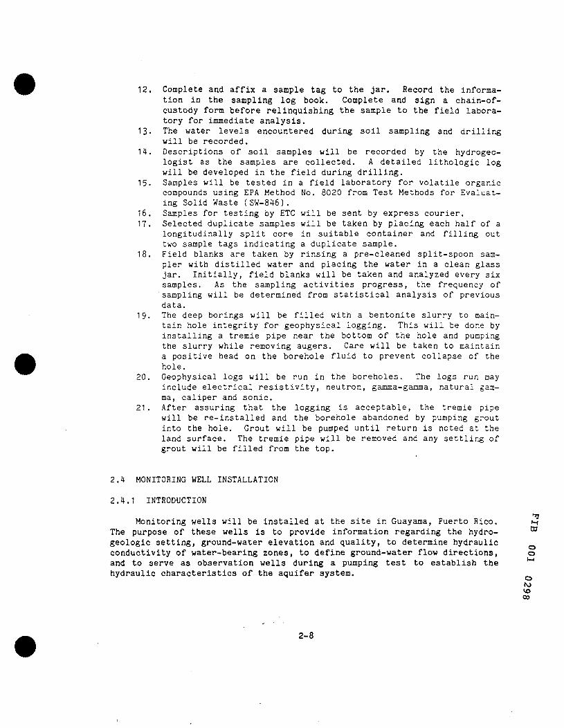
21. After assuring that the logging is acceptable, the tremie pipe will be re-installed and the borehole abandoned by pumping grout into the hole. Grout will be pumped until return is noted at the land surface. The tremie pipe will be removed and any settling of grout will be filled from the top.
2.4 MONITORING WELL INSTALLATION
2.4.1 INTRODUCTION
' Monitoring wells will be installed at the site in Guayama, Puerto Rico. H
The purpose of these wells is to provide information regarding the hydro- ^ geologic setting, ground-water elevation and quality, to determine hydraulic conductivity of water-bearing zones, to define ground-water flow directions, o and to serve as observation wells during a pumping test to establish the *"" hydraulic characteristics of the aquifer system,
NJ VO 00
2-8
•
•
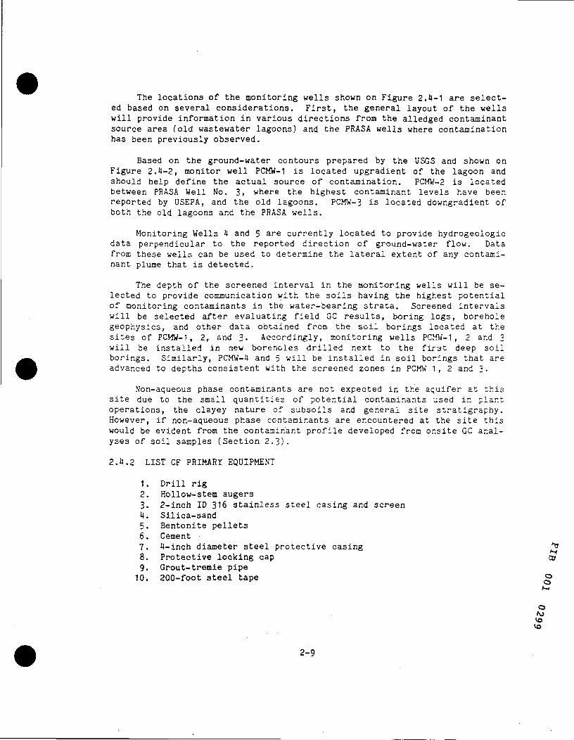
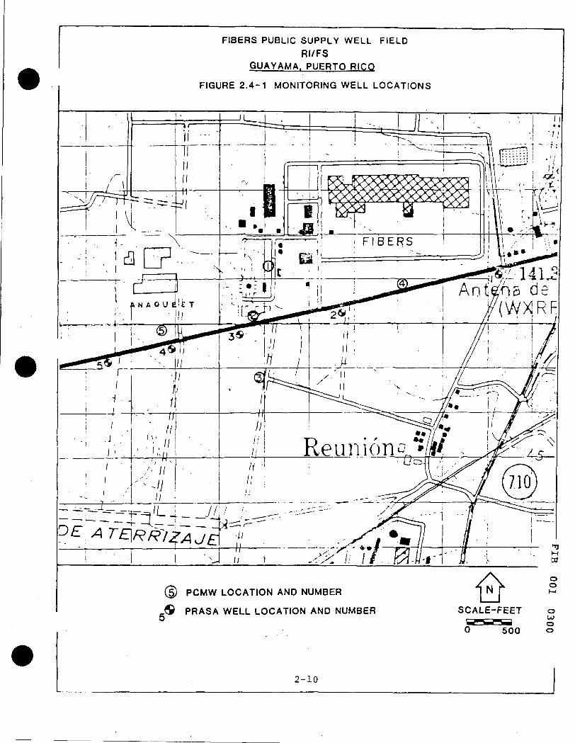
The locations of the monitoring wells shown on Figure 2,4-1 are selected based on several considerations. First, the general layout of the wells will provide information in various directions from the alledged contaminant source area (old wastewater lagoons) and the PRASA wells where contamination has been previously observed.
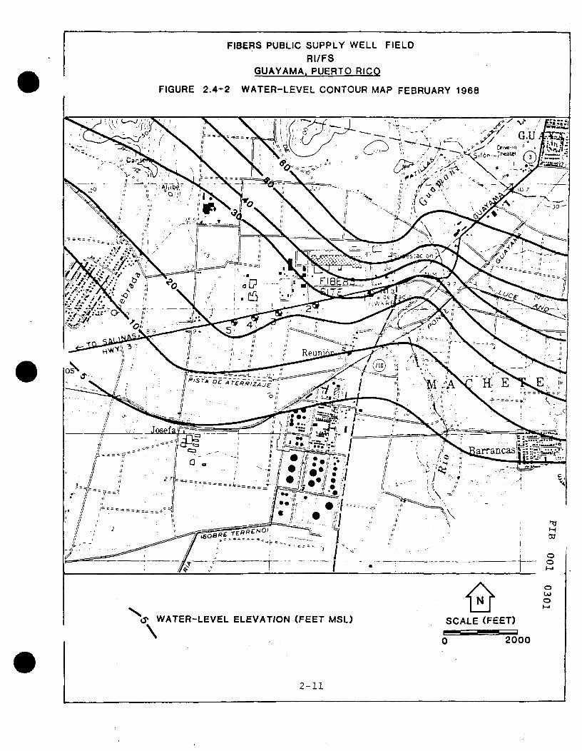
Based on the ground-water contours prepared by the USGS and shown on Figure 2.4-2, monitor well PCMW-1 is located upgradient of the lagoon and should help define the actual source of contamination. PCMW-2 is located between PRASA Well No. 3, where the highest contaminant levels have been reported by USEPA, and the old lagoons. PCMW-3 is located downgradient of both the old lagoons and the PRASA wells.
Monitoring Wells 4 and 5 are currently located to provide hydrogeologic data perpendicular to the reported direction of ground-water flow. Data from these wells can be used to determine the lateral extent of any contaminant plume that is detected.
The depth of the screened interval in the monitoring wells will be selected to provide communication with the soils having the highest potential of monitoring contaminants in the water-bearing strata. Screened intervals will be selected after evaluating field GC results, boring logs, borehole geophysics, and other data obtained from the soil borings located at the sites of PCMW-?, 2, and 3. Accordingly, monitoring wells PCMW-1, 2 and 3 will be installed in new boreholes drilled next to the first deep soil borings. Similarly, PCMW-4 and 5 will be installed in soil borings that are advanced to depths consistent with the screened zones in PCMW 1, 2 and 3.
Non-aqueous phase contaminants are not expected in the aquifer at this site due to the small quantities of potential contaminants used in plant operations, the clayey nature of subsoils and general site stratigraphy. However, if non-aqueous phase contaminants are encountered at the site this would be evident from the contaminant profile developed from onsite GC analyses of soil samples (Section 2.3).
2.4.2 LIST OF PRIMARY EQUIPMENT
1. Drill rig 2. Hollow-stem augers 3. 2-inGh ID 316 stainless steel casing and screen 4. Silica-sand 5. Bentonite pellets 6. Cement 7. 4-inch diameter steel protective casing ^ 8. Protective locking cap Co 9. Grout-tremie pipe
10. 200-foot s t ee l tape o
o NJ vo vo
2-9
(§) PCMW LOCATION AND NUMBER
, ^ PRASA WELL LOCATION AND NUMBER ^
o o
SCALE-FEET o
0 500 S
2-10
FIBERS PUBLIC SUPPLY WELL FIELD RI/FS
GUAYAMA. PUERTO RICO
FIGURE 2.4-2 WATER-LEVEL CONTOUR MAP FEBRUARY 1968
> WATER-LEVEL ELEVATION (FEET MSL)
\ SCALE (FEET)
2000
2 - 1 1

2.4.3 PROCEDURE
1. Prior to commencement of drilling operations, site maps will be reviewed with regards to underground pipes and electrical cables. Written authorization for drilling from plant safety personnel will be obtained prior to drilling operations on AHP property.
2. The drill crew will be under the direct supervision of the on-site manager,
3. The drill rig will be steam-cleaned between monitor-well sites, 4. Six-inch (6") hollow stem augers will be used for drilling opera
tions. 5. Prior to installation, the two-inch diameter well casing and
screens will be kept in packing boxes; the steam-cleaned augers will be stored on plastic sheeting so as to minimize contamination possibilities.
6. The on-site manager will confirm the depth of the boring with a measuring tape once it has been determined that the final depth of the borehole has been reached.
7. The boreholes will be completed using clean augers and advanced to the bottom screen depth. The only sampling conducted in these boreholes would be for undisturbed samples (Shelby Tubes) for special geotechnical testing.
8. Well casings and screens will be two-inch diameter 316 stainless steel.
9. After boring to the selected final depth, and the integrity of the borehole has been confirmed, the casing and screen will be installed.
10. A silica sand will surround the screen and extend to approximately three feet above the screen.
11. Two foot bentonite seal will be placed above the sand. 12. The remainder of the annulus will be filled with a
cement/bentonite slurry to land surface using a tremie pipe system. A cement paid will be placed around each well that will direct surface water away from the casing.
13. A protective four-inch steel surface casing will be placed around each well casing. Locking caps will be installed on each well casing.
14. If, during completion of the monitoring well and prior to placement of the bentonite seal or before initial installation, the hole collapses, the hole will be redrilled with clean hollow stem augers to the original depth and installation will be completed through the augers.
16. When installing the monitoring pipe through the auger, special ^ care must be taken when placing the bentonite seal so as not to ^ create a plug inside the auger. Bentonite pellets must be dropped slowly and separately to ensure correct installation. o
o
o v>J o to
2-12

17. Following installation of all five monitoring wells, cased hole geophysical logs (neutron and natural gamma) will be run.
2.5 HYDROLOGIC TESTING
2.5.1 INTRODUCTION
The development and testing of the monitor wells PCMW-1 through 5 will require several specific actions. Each of these activities is described below.
2.5.2 WELL DEVELOPMENT
Following monitor-well construction each well will be pumped, by air or suction, to clear the well and gravel pack of fine-grained materials. This activity allows for the assurance that the well screen is in good hydraulic connection with the aquifer and that water samples free of sediments will be obtained. The equipment and procedures for this activity are described below.
2.5.2.1 LIST OF PRIMARY EQUIPMENT
1 . Air compressor and associated hoses 2. Discharge pipe and/or hose 3. Clear glass jar (1 quart minimum) 4. 100-foot steel tape 5. Portable tank
2.5.2.2 PROCEDURE
1. Determine depth to water with tape. 2. Install pumping system. 3. Pump the well at highest rate practical. 4. Direct the discharge to an appropriate disposal/storage point. It
may be necessary to utilize a portable tank for discharge collection and transportation to the storage/disposal point,
5. Inspect the discharge water for turbidity intermittently by filling the glass jar and allowing the particulate matter, if any, to settle, "
6. Measure the water level intermittently to determine the amount of W drawdown caused by pumpage.
7. Terminate pumping when the discharge is no longer turbid and drawdowns are relatively stable.
8. Record the pumping rate, duration, and water-level drawdown and recovery.
o o
o LO o
2-13
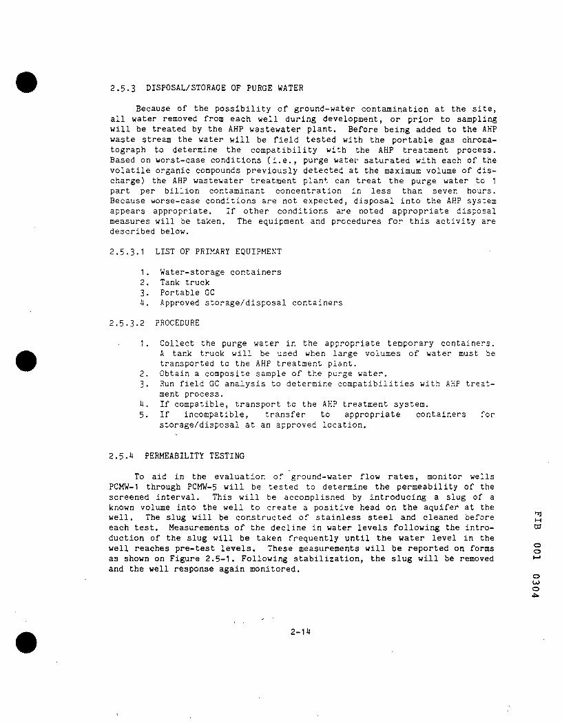
2.5.3 DISPOSAL/STORAGE OF PURGE WATER
Because of the possibility of ground-water contamination at the site, all water removed from each well during development, or prior to sampling will be treated by the AHP wastewater plant. Before being added to the AHP waste stream the water will be field tested with the portable gas chromatograph to determine the compatibility with the AHP treatment process. Based on worst-case conditions (i.e., purge water saturated with each of the volatile organic compounds previously detected at the maximum volume of discharge) the AHP wastewater treatment plant can treat the purge water to 1 part per billion contaminant concentration in less than seven hours. Because worse-case conditions are not expected, disposal into the AHP system appears appropriate. If other conditions are noted appropriate disposal measures will be taken. The equipment and procedures for this activity are described below.
2.5.3.1 LIST OF PRIMARY EQUIPMENT
1. Water-storage containers 2. Tank truck 3. Portable GC 4. Approved storage/disposal containers
2.5.3.2 PROCEDURE
1. Collect the purge water in the appropriate temporary containers. A tank truck will be used when large volumes of water must be transported to the AHP treatment plant.
2. Obtain a composite sample of the purge water. 3. Run field GC analysis to determine compatibilities with AHP treat
ment process. 4. If compatible, transport to the AHP treatment system. 5. If incompatible, transfer to appropriate containers for
storage/disposal at an approved location,
2.5.4 PERMEABILITY TESTING
To aid in the evaluation of ground-water flow rates, monitor wells PCMW-1 through PCMW-5 will be tested to determine the permeability of the screened interval. This will be accomplished by introducing a slug of a known volume into the well to create a positive head on the aquifer at the well. The slug will be constructed of stainless steel and cleaned before ^ each test. Measurements of the decline in water levels following the Intro- co duction of the slug will be taken frequently until the water level in the well reaches pre-test levels. These measurements will be reported on forms § as shown on Figure 2,5-1, Following stabilization, the slug will be removed "-• and the well response again monitored,
o U) o
2-14
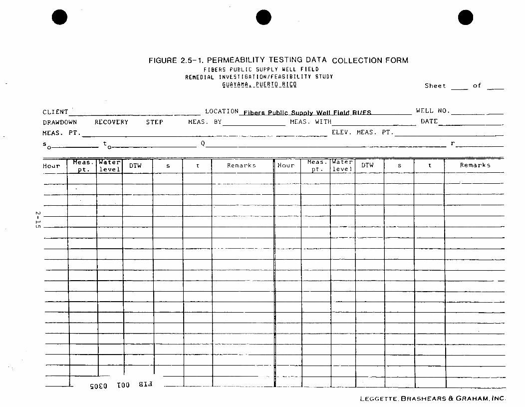
FIGURE 2 . 5 - 1 . PERMEABILITY TESTING DATA COLLECTION FORM FIBERS PUBLIC SUPPLY WELL FIELD
REHEDIAL INVESTIGATION/FEASIB IL ITY STUDY GyAYAhAi_PyERig_RlCO S h e e t o f
CLIENT
DRAWDOWN
MEAS. PT.
s
RECOVERY STEP
LOCATION FihBra Puhl l r Supply W»ll FI»M RI/F.Cj
MEAS. BY MEAS. WITH
WELL NO.
DATE
ELEV. MEAS. PT.
H o a r
KJ 1
Heas . p t .
•
SO
Water l e v e l
£0 K
DTW
)0 a i a
s t Remarks Hour Meas. p t .
Water leve 1 DTW s t Remarks
LEGGETTE. B R A S H E A R S & G R A H A M . INC.
The data from these tests will be field reduced and plotted to assure accurate data collection and to determine the need to retest the well. Analysis of the data will be by methods developed by Hvorslev (1959) or Ferris, et al. (1962).
2.5.4.1 LIST OF PRIMARY EQUIPMENT
1. Stainless-steel slug 2. Stainless-steel cable 3. Transducer unit or steel tape for monitoring water-level changes 4. Graph paper
2.5.4.2 Procedure
1. Measure depth to water from the designated measuring point. 2. If appropriate, install transducer into the well and record water
level above the transducer. 3. Drop slug into well and monitor water-level changes at frequent
intervals. 4. Record the water-level measurements and times on the
forms provided. 5. After stabilization, pull slug and again monitor water-level
changes. 6. Reduce and plot data for evaluation. 7. Calculate the permeability of the screened section of the aquifer.
2.5.5 WATER-LEVEL MEASUREMENTS
Water-level measurements taken during the investigation will utilize, to the extent possible, a steel tape marked in feet, tenths of a foot and hundredths of a foot. In those cases where tape measurements cannot be taken, an electronic tape similar to the QED Sample Pro Electronic Water Level Meter will be used. During permeability testing, a transducer unit may be , used.
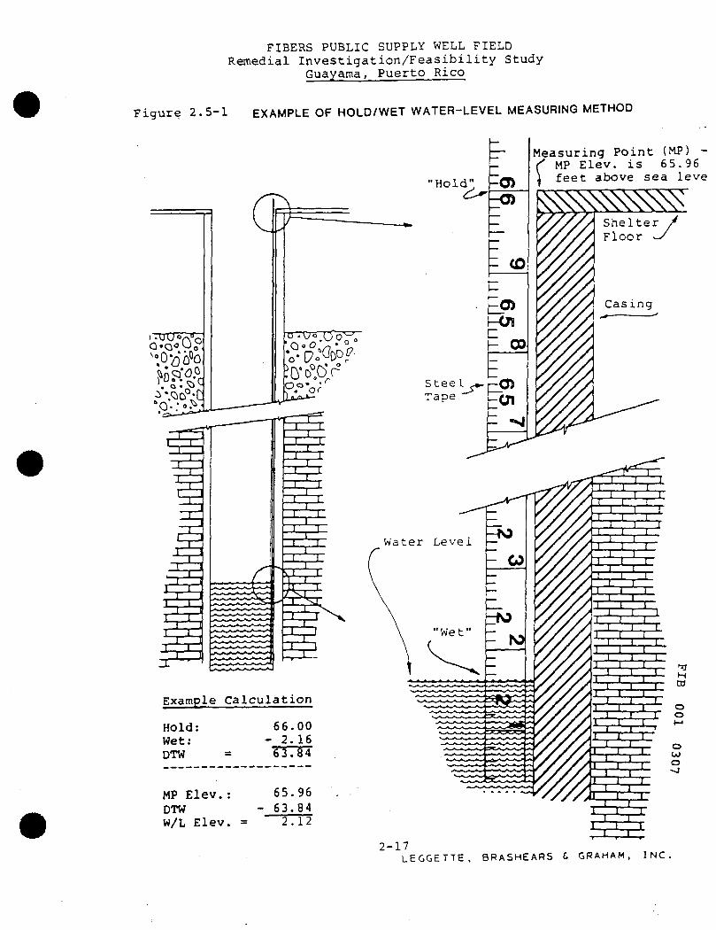
Steel-tape measurements will be taken using the "hold/wet" method. In this method the tape is lowered into the well and the amount of tape "wet" is subtracted from the "hold" mark. An example of this method is shown on Figure 2.5-2,
All measurements will be recorded in the field on separate pages for each well. Any unusual measurements will be re-taken to confirm their accu- ,1 racy. When re-taping, a different "hold" mark will be used, n
CO
o o M
O OJ O
2-16
FIBERS PUBLIC SUPPLY WELL FIELD Remedial Investigation/Feasibility Study
Guayama, Puerto Rico
Figure 2.5-1 EXAMPLE OF HOLD/WET WATER-LEVEL MEASURING METHOD
O.QoOO
T 1 1
I J 1
1 1
1 ' I 1 r , 1 J ] 1
1 i _L
Example Calculation
Hold: Wet: DTW =
MP Elev.: DTW W/L Elev. =
66.00 - 2.16 63.84
65.96 - 63.84
2.12
Measuring Point (MP) -MP Elev. is 65.96 feet above sea leve
$ > ^ " ^ ^ ^ Shelter Floor
Casing
2-17 LEGGETTE. BRASHEARS C GRAHAM, INC.
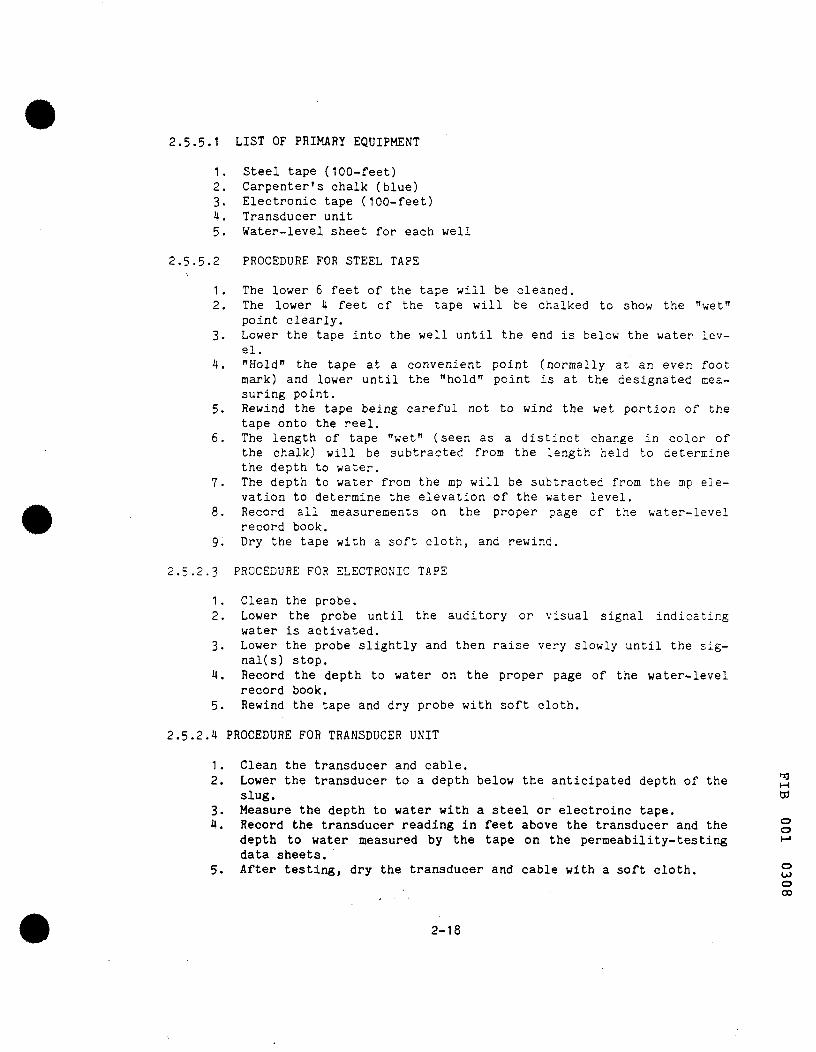
2.5.5.1 LIST OF PRIMARY EQUIPMENT
1. Steel tape (100-feet) 2. Carpenter's chalk (blue) 3. Electronic tape (100-feet) 4. Transducer unit 5. Water-level sheet for each well
2.5.5.2 PROCEDURE FOR STEEL TAPE
1. The lower 6 feet of the tape will be cleaned. 2. The lower 4 feet of the tape will be chalked to show the "wet"
point clearly. 3. Lower the tape into the well until the end is below the water lev
el, 4. "Hold" the tape at a convenient point (normally at an even foot
mark) and lower until the "hold" point is at the designated measuring point.
5. Rewind the tape being careful not to wind the wet portion of the tape onto the reel.
6. The length of tape "wet" (seen as a distinct change in color of the chalk) will be subtracted from the length held to determine the depth to water.
7. The depth to water from the mp will be subtracted from the mp elevation to determine the elevation of the water level.
8. Record all measurements on the proper page of the water-level record book.
9. Dry the tape with a soft cloth, and rewind.
2.5.2.3 PROCEDURE FOR ELECTRONIC TAPE
1. Clean the probe. 2. Lower the probe until the auditory or visual signal indicating
water is activated. 3. Lower the probe slightly and then raise very slowly until the sig-
nal(s) stop, 4. Record the depth to water on the proper page of the water-level
record book, 5. Rewind the tape and dry probe with soft cloth.
2.5.2.4 PROCEDURE FOR TRANSDUCER UNIT
1. Clean the transducer and cable. 2. Lower the transducer to a depth below the anticipated depth of the '^
slug. 03 3. Measure the depth to water with a steel or electroinc tape. 4. Record the transducer reading in feet above the transducer and the °
depth to water measured by the tape on the permeability-testing •-' data sheets.
5. After testing, dry the transducer and cable with a soft cloth, 2 o 00
2-18

2.6 GROUND-WATER SAMPLING
2.6.1 INTRODUCTION
Ground-water samples will be collected from the five PRASA production wells and one AHP well as soon as the SOP has been approved by the USEPA. These samples will be analyzed in the field with the portable GC unit for volatile organic compounds. These data will be compared to the I983 data and, should significant differences be noted, modifications to the RI may be necessary.
Samples will also be collected from the five monitor wells discussed in, the five PRASA wells and from one AHP production well for analysis by ETC. These analyses will establish the quality of the ground water ente.-ing and leaving the site. A second round of samples will also be collected from these same wells to determine what changes, if any, occur over a period of time.
2.6.2 LIST OF PRIMARY EQUIPMENT
1. Stainless steel bailers dedicated to each well 2. Steel or electronic tape 3,' A portable pH meter 4. Thermometer 5. A portable conductivity meter 6. l6-ounce wide-mouth jars 7. A standard set of sample bottles for each well 8. Appropriate protective clothing and gloves 9. Chain-of-custody forms 10. Sample labels 11. Submersible well pump and portable electric generator
2.6.3 PROCEDURE FOR MONITOR WELLS
1. Groundwater samples will be collected by field personnel under the supervision of the on-site QA officer.
2. Water samples to be analyzed in the field with a GC unit will be collected in pre-cleaned l6-ounce wide-mouth jars. Water saccles collected for shipment to ETC will be collected in sealed, precleaned bottles.
3. Use steam-cleaned stainless-steel bailers to collect samples. One bailer will be dedicated to each monitoring well. g
4. Before sampling, measure the static water level in the well with a ^ steel or electronic tape and record the measurement,
5. Calculate the volume of water in the well from the well depth, the o static water level, and the casing diameter. 2
6. Bail water from the monitoring wells until field measurements of temperature, pH and conductivity stabilize or at least 3 well vol- o umes are removed. The water removed from the well will be stored ^
2-19

in a portable storage tank prior to final disposal in the on-site waste-treatment facility,
7. Pour water down the side of the sample vial or jar to minimize turbulence during sample collection. For samples collected in vials, invert the vial once it is filled to ensure that there are no air bubbles. If air bubbles are found, another sample must be taken.
8. Fill containers, for field GC analysis (l6-ounce wide-ujouth jars) approximately half full with sample water. The glass jars will be sealed with teflon lined lids and screw caps.
9. Complete and affix a sample tag to each sample container. For samples that will be shipped to ETC, the tag will be protected with clear vinyl tape.
10. Check the sample number assigned to each bottle against the sample number on the chain-of-custody form.
11. Samples requiring preservation will have premeasured preservatives affixed to the bottles when they arrive on site. Samples to be shipped to ETC will be preserved as per instructions, supplied
- with the bottles. 12. Samples to be analyzed in the field will be taken to the field
laboratory for immediate analysis. A chain-of-custody form will be signed before the samples are relinquished.
13. Sample for ETC testing will be shipped by express courier.
2.6.4 PROCEDURE FOR WATER SAMPLING AT PRASA WELLS AND THE AHP WELL
1 . Prior to sampling, information will be compiled from PRASA or AHP regarding well size, pump type, yield, well reliability and electrical connections, and start-up procedures.
2. The wells will be sampled from a sampling point as close tc the pump as possible.
3. Discharged (purge) water from the PRASA wells will be stored in a portable storage tank prior to final disposal in the on-site treatment facility. Purge water from the AHP well will enter the AHP water-supply system.
4. At PRASA Well 3, a sample will be taken by bailer for field GC analysis prior to purging the well.
5. Prior to collection of the pumped sample, the pump will be run until field measurements of pH, temperature and conductivity stabilize or until 3 casing volumes of water have been removed.
6. When sampling from a water tap or water line, the packing should be tight and aerators must be removed to prevent a loss of vola- ' tile organics. BJ Water samples to be analyzed by the field GC will be collected in pre-cleaned l6-ounce wi and screw caps. These sample water and sealed.
pre-cleaned l6-ounce wide-mouth glass jars with teflon-lined lids o and screw caps. These jars will be filled about half full with M
o
2-20

8. Collect the samples for ETC analysis in a standard set of bottles. 9. When collecting samples for volatile organics analysis, pour water
down the side of the vial so as to minimize turbulence. Invert the vial when full and look for air bubbles. If bubbles are found, discard the sample and use another clean vial to collect a new sample.
10, Complete and affix a sample tag to each container. 11. Sign a chain-of-custody form before relinquishing the sample.
2.7 SURFACE-WATER SAMPLING
2.7.1 INTRODUCTION
Information shown on Figure 2.7-1, a topographic map of the area, indicates the presence of a surface water divide between the Guamani River and the AHP site. This divide prevents the movement of surface water to the river from the plant site. Likewise, ground-water information developed by the USGS and shown on Figure 2,4-1 indicate that in the area of the AHP plant, flow is to the southwest away from the river. For these reasons, surface-water sampling of the river is not anticipated as a part of the RI.
Should information be,developed during the site-specific field investigations that indicates an interaction between the Guamani Rivert and the AHP site does exist, the surface-water sampling program described below will be undertaken.
2.7.2 LIST OF PRIMARY EQUIPMENT
1. A standard set of sample bottles for each sample locations 2. l6-ounce wide-mouth jars 3. Protective gloves 4. A portable pH meter 5. Thermometer 6. A portable conductivity meter 7. Distilled water 8. A pre-cleaned "bail bottle" for each location
2.7.3 PROCEDURE
1, Samples collected for field analysis will be placed in l6-ounce wide-mouth jars. The jars will be sealed with teflon-lined lids ^ and screw caps. Samples collected for ETC analysis will be placed W in sealed, precleaned bottles. A standard set of bottles for each sample will be provided by ETC. g
2, Use protective gloves on the hand used to dip the bottles into the f-* surface-water body.
o 00
2-21

FIBERS PUBLIC SUPPLY WELL FIELD RI/FS
GUAYAMA. PUERTO RICO
FIGURE 2.7-1 SURFACE-WATER DRAINAGE PATTERN

3. Submerge the bail bottle upside down just below the water surface. Invert the container slowly to allow it to fill with the surrounding water,
4. Remove the bail bottle and fill the sample containers that have preservatives with water from the bail bottle,
5. For sample collection in bottles and vials without preservative; collect the sample bottles directly from the surface-water body.
6. Invert the viali containing the samples for volatile organic analysis to ensure there are no air bubbles in the sample. If bubbles are found; discard that sample and collect another sample in a spare sample bottle.
7. Cap each sample container as soon as the sample is collected. 8. Collect an additional water sample in a clean l6-ounce glass jar
for immediate measurement of temperature, pH, and conductivity. 9. Sign a chain-of-custody form before relinquishing the samples. 10. Samples collected for ETC analysis will be shipped via express
courier. 11. Surface water samples will be analyzed for pH, temperature and
conductivity in the field.
2.8 SEDIMENT SAMPLING
2.8.1 INTRODUCTION
Section 2.7.1 of the SOP presents information describing why surface-water sampling of the Guamani River will not be undertaken as a part of the RI. This same rationale applies to sediment sampling of the river.
Should information be developed during the site-specific field investigations that indicates an interaction between the Guamani River and the AHP site does exist the sediment sampling program described below will be undertaken.
2.8,2 LIST OF PRIMARY EQUIPMENT
1, Gravity corer 2, l6-ounce wide-mouth jars 3, A standard set of bottles for each sample 4, Stainless steel lab spoon M 5, Protective gloves ^
o o
o OJ M OJ
2-23

2,8,3 PROCEDURE
1. A gravity corer will be used for collecting the sediment samples, 2. Attach the pre-cleaned corer to the required length of sample
line, 3. Secure the free end of the line to a fixed support to prevent ac
cidental loss of the corer. 4. Drop corer freely to allow it to fall through the surface water. 5. Retrieve the corer with a smooth, continuous lifting motion. 6. Remove nosepiece from corer and slide sample out of corer into
sample bottles with a stainless steel lab spoon, 7. For samples to be analyzed by the field GC, the samples will be
collected in l6-ounce wide-mouth jars and capped tightly with teflon-lined lids and screw caps.
8. Samples to be sent to ETC for analysis will be collected in the standard set of bottles supplied by ETC.
9. Complete and affix a sample tag to the bottles. 10. Sign a chain-of-custody form before relinquishing the samples for
analysis.
2.9 WATER-QUALITY ANALYSIS
2.9.1 INTRODUCTION
ETC will run laboratory analysis on ground-water samples collected from the 5 PRASA wells, the 5 monitoring wells and from one AHP well. If it is necessary to obtain water samples from the Guamani River, laboratory analysis of these samples will be run. On-site testing of water quality parameters including pH, conductivity, temperature and volatile organics will be performed on all samples. As a certified USEPA contract laboratory, ETC will utilize contract laboratory procedures during analytical activities.
The specific laboratory analyses to be run on the first round of water samples is listed in Appendix 4-A. These analyses include the constituents on the hazardous substances list as specified by the USEPA and included in the Administrative Order. This list includes the contaminants previously detected in the PRASA wells and their hazardous biodegradation products. Subsequent analysis of water samples may be run on a limited list of substances depending on the results of the first round.
Field analyses of all water samples will also be run with a portable GC unit.
M DO
o o
o OJ
2-24
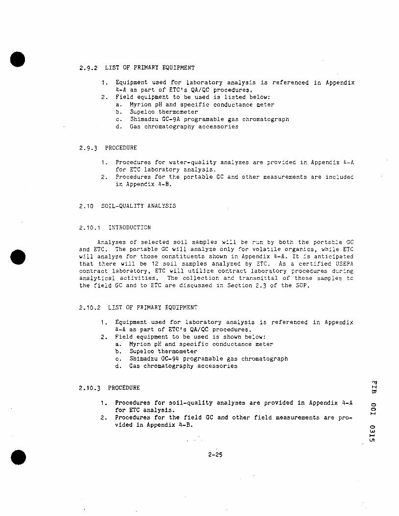
2.9.2 LIST OF PRIMARY EQUIPMENT
1. Equipment used for laboratory analysis is referenced in Appendix 4-A as part of ETC's QA/QC procedures.
2. Field equipment to be used is listed below: a. Myrion pH and specific conductance meter b. Supelco thermometer c. Shimadzu GC-9A programable gas chromatograph d. Gas chromatography accessories
2.9.3 PROCEDURE
1. Procedures for water-quality analyses are provided in Appendix 4-A for ETC laboratory analysis.
2. Procedures for the portable GC and other measurements are included in Appendix 4-B.
2.10 SOIL-QUALITY ANALYSIS
2.10.1 INTRODUCTION
Analyses of selected soil samples will be run by both the portable GC and ETC. The portable GC will analyze only for volatile organics, while ETC will analyze for those constituents shown in Appendix 4-A. It is anticipated that there will be 12 soil samples analyzed by ETC. As a certified USEPA contract laboratory, ETC will utilize contract laboratory procedures during analytical activities. The collection and transmittal of these samples to the field GC and to ETC are discussed in Section 2.3 of the SOP.
2.10.2 LIST OF PRIMARY EQUIPMENT
1. Equipment used for laboratory analysis is referenced in Appendix 4-A as part of ETC's QA/QC procedures.
2. Field equipment to be used is shown below: a. Myrion pH and specific conductance meter b. Supelco thermometer c. Shimadzu GC-94 programable gas chromatograph d. Gas chromatography accessories
2.10.3 PROCEDURE ^ DO
1. Procedures for soil-quality analyses are provided in Appendix 4-A for ETC analysis.
2. Procedures for the field GC and other field measurements are provided in Appendix 4-B.
2-25
o o
o OJ
on
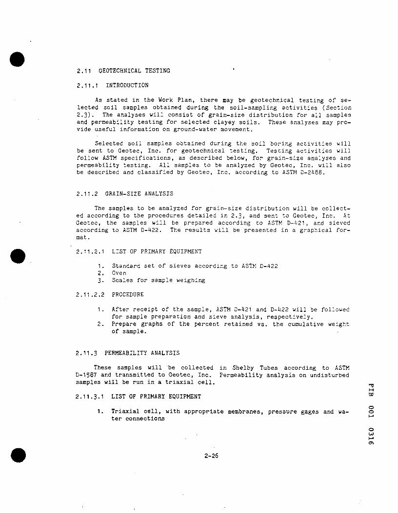
2,11 GEOTECHNICAL TESTING
2.11.1 INTRODUCTION
As stated in the Work Plan, there may be geotechnical testing of selected soil samples obtained during the soil-sampling activities (Section 2.3). The analyses will consist of grain-size distribution for all samples and permeability testing for selected clayey soils. These analyses may provide useful information on ground-water movement.
Selected soil samples obtained during the soil boring activities will be sent to Geotec, Inc. for geotechnical testing. Testing activities will follow ASTM specifications, as described below, for grain-size analyses and permeability testing. All samples to be analyzed by Geotec, Inc. will also be described and classified by Geotec, Inc. according to ASTM D-2488.
2.11.2 GRAIN-SIZE ANALYSIS
The samples to be analyzed for grain-size distribution will be collected according to the procedures detailed in 2.3, and sent to Geotec, Inc. At Geotec, the samples will be prepared according to ASTM D-421 , and sieved according to ASTM D-422. The results will be presented in a graphical format.
2.11.2.1 LIST OF PRIMARY EQUIPMENT
1. Standard set of sieves according to ASTM D-422 2. Oven 3. Scales for sample weighing
2.11.2.2 PROCEDURE
1. After receipt of the sample, ASTM D-421 and D-422 will be followed for sample preparation and sieve analysis, respectively.
2. Prepare graphs of the percent retained vs. the cumulative weight of sample.
2.11.3 PERMEABILITY ANALYSIS
These samples will be collected in Shelby Tubes according to ASTM D-1587 and transmitted to Geotec, Ine, Permeability analysis on undisturbed samples will be run in a triaxial cell,
M 2.11.3.1 LIST OF PRIMARY EQUIPMENT '
o 1. Triaxial cell, with appropriate membranes, pressure gages and wa- o
ter connections *"* o OJ
a\
2-26

2,11,3.2 PROCEDURE
1. Obtain sample in Shelby Tube. 2. Extract sample from tube. 3. Trim sample to fit the membrane of the triaxial cell. 4. Place sample into membrane and then into cell, 5. While maintaining the proper external pressure to simulate in-situ
conditions, percolate water through the sample and measure rate of discharge.
6. Calculate permeability of the sample.
2,12 AQUIFER TESTING
2,12,1 INTRODUCTION
An aquifer test will be conducted to determine the hydraulic properties of the aquifer beneath the AHP site. Based on the existing well locations, AHP Production Well No, 4 (4120.OON, 4016.OOE) will be used as the pumping well, with other on-site wells to the south and east serving as observation wells. Water pumped during the aquifer test will be contained in the AHP water distribution and storage system, thereby eliminating the need for additional discharge piping and the location of a new discharge point.
2.12,2 LIST OF PRIMARY EQUIPMENT
1. Pumping well 2. Steel measuring tapes 3. Pump-test data sheets (Figure 2.12-1) 4. Discharge flow meter 5. Reording microbarograph 6. Rain gage
2.12.2 PROCEDURE
1. Install microbarograph. 2. Measure pumping wells and monitor wells and record the
data on forms provided. 3. Pre-set pumping rate, discharge valves, etc. 4. Start test. " 5. Measure levels in pumping and monitor wells frequently, od 6. Record data on the appropriate pump-test data sheets. 7. Run test until sufficient data are obtained to evaluate the hydro- g
logic system. HJ 8. Shut-down test. 9. Monitor water-level recovery in the pumping and monitor wells. '^ 10. Evaluate test data with appropriate methodology. M
2-27
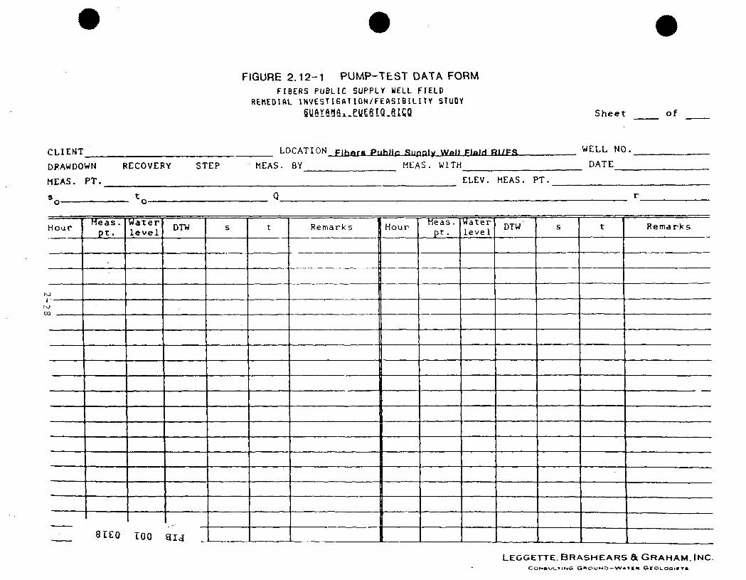
FIGURE 2.12-1 PUMP-TEST DATA FORM
FIBERS PUBLIC SUPPLY WELL FIELD REHEDIAL INVESTIGATION/FEASIBILITY STUDY
S h e e t o f
CLIENT
DFAWDOWN
MEAS. PT.
s
RECOVERY STEP
LOCATION Fihftra PtjhIlr .Supply Wall PIftlH Rl/FR
MEAS. BY MEAS. WITH
WELL NO.
DATE
ELEV. MEAS. PT.
H o a r
(O
rr)
Heas . p t .
Water l e v e l
STEO TOO
DTW
a i j
s
._,
t Remarks
,
Hour Meas. p t .
Water l e v e l
DTW s t Remarks
LEGGETTE. BRASHEARS & GRAHAM. INC.

2.13 COMPUTER MODELING
2.13.1 INTRODUCTION
The USGS has developed an analog (electrical) model of the south coast of Puerto Rico, including the project area (Bennet, 1976). This model was used by the USGS in 1978 to investigate the water budget for the region as well as the potential for artificial recharge (Heisel, et al, 1978). Diaz (1971) developed an electrical analog model for the Guayama area and described its development and use in USGS OFR-57.
This analog model does not provide the ability for contaminant-plume simulation. Since a model developed for this investigation should have the capability of such simulation, a digital computer model would be required.
The use of ground-water flow modeling to simulate site conditions will be undertaken only if the data collected during the investigation indicate that such activities will provide a practical advantage to the RI and assist in evaluating remedial alternatives during the FS. Should conditions warrant the development of a model, it would be appropriate to first select a solute-transport analytical model consistent with available data. If the analytical model satisfactorily simulates contaminant-plume migration, additional modeling would not be needed. If, however, it is considered appropriate to develop a more sophisticated model, a digital model would be developed, so long as data are available to support it. The equipment and procedures for development and usage of the model(s) are shown below.
2.13.2 LIST OF PRIMARY EQUIPMENT
1. An IBM PC/AT computer 2. A Hayes 1200 Smartmodem 3. An Intel AS-6 mainframe computer (Litton Computer
Service) 4. An IBM Color printer 5. An EPSON 185 printer 6. The chosen analytical model 7. The chosen computer code
2.13.3 PROCEDURES
1. Review data. 2. Choose model, frj 3. Model-code verification run. ^ 4. Prepare and input data. 5. Calibrate model to site conditions, o 6. Verify model to different conditions. o
o OJ
vo
2-29
7. Run sensitivity analysis. 8. Predict ground-water flow conditions and contaminant transport.
2.14 DATA VALIDATION, EVALUATION AND RI REPORT PREPARATION
Data generated throughout the RI will be validated and evaluated as it is developed. This will enable decisions to be made regarding subsequent RI tasks and allow early preparation of preliminary drafts of specific sections of the RI report. Validation methodology for field and laboratory analytical procedures are described in Chapter 4 of the SOP, SITE SPECIFIC QUALITY ASSURANCE/QUALITY CONTROL DOCUMENT.
The data validation and evaluation processes described in Chapter 4 and the associated appendices will result in reliable, accurate data upon which to base the RI report.
o o
o OJ to o
2-30
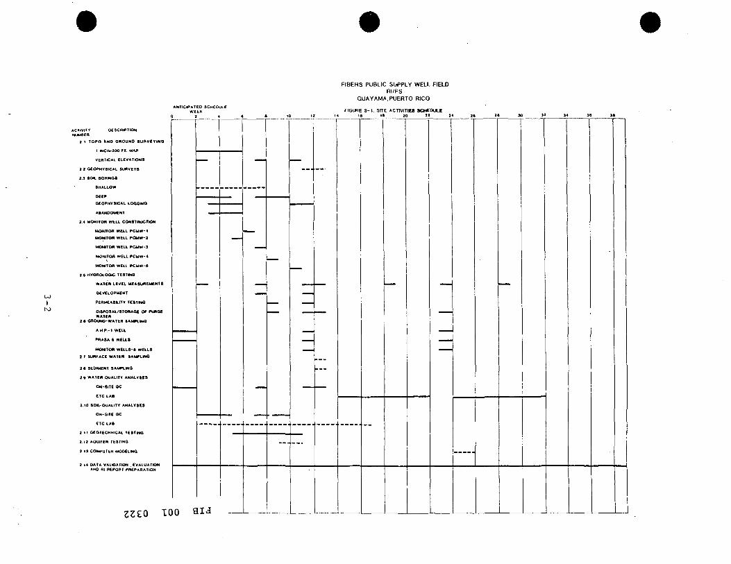
3,0 SITE ACTIVITIES SCHEDULE
The site activities have been organized to provide an efficient and timely progression of the project. As in all field activities, the schedule shown in Figure 3-1 may be modified during the project. Notification of changes in the schedule will accompany the monthly progress reports required by the administrative order.
M D3
o o
o OJ
3-1
I
ANTICIPATED SCHEDULE WEEK
FIBERS PUBLIC SUPPLY W E U FIELD RI/FS
GUAYAMA. PUERTO RICO
F I G U R E 3 - 1 . 3 f T E A C n V I T t t a » C M t O U L £
ACTIVITY NUMBER
DESCRIPTION
2 1 TOPo ANO OROUND aunvfYiHO
I iNCH-300 FT. MAP
VERTICAL EL£VATtON9
2 3 aCOPHVSICAL SURVEYS
2.9 aOK. B 0 R I N 0 8
SHALLOW
D e e p
OEOPHYSICAL LOaOINQ
A B A N O O M C N T
3.4 MONITOR WELL CONSTRUCTION
MONITOR WELL P C M W - 1
MONITOR WELL P C M W - 2
MONITOR WELL P C M W - 3
MONITOR WELL P C M W - 4
MONITOR WELL P C M W - 6
2.B HYOROLOOlC TESTMQ
WATER LEVEL MEASUREMENTS
DEVELOPMENT
PeRMEABILITV TESTINO
DISPOSAL/STORAGE O f PUROC WATER
3.e GROUND-WATER SAMPLING
AM,P . -1 WELL
PRASA-S WELLS
MONITOR WELLS-S wCLLS
3.r SURFACE WATCn SAMPLING
2 . t SEDIMENT SAMPLING
2.» WATER QUALITY ANALYSES
ON-SITE GC
ETC LAB
3.10 80 IL -0UAL ITY ANALYSES
ON-SITE GC
ETC LAB
3 I t GEOTECHNICAL TESTING
3.12 AQUIFER TESTING
3 i 3 COMPUTER MODELING
3 14 DATA VALIDATION . EVALUATION AND Rl REPORT PREPARATION
23eo TOO a i d
SITE SPECIFIC
QUALITY ASSURANCE/QUALITY CONTROL DOCUMENT
REMEDIAL INVESTIGATION/FEASIBIL ITY STUDY
F ibers Public Supply Well F ie ld
G u a y a m a , Pue r to Rico
P r e p a r e d by
LEGGETTE, BRASHEARS & GRAHAM. INC.
1211 North W e s t s h o r e Bou leva rd
Tampa , F lor ida 3 3 6 0 7
APRIL. 1986 "3
O O
o I j j to

4,1 TITLE PAGE
SITE SPECIFIC QUALITY ASSURANCE/QUALITY CONTROL DOCUMENT
FOR FIBERS PUBLIC SUPPLY WELL FIELD
REMEDIAL INVESTIGATION/FEASIBILITY STUDY
GUAYAMJl. PUERTO RICO
USEPA ADMINISTRATIVE ORDER Index No. II - CERCLA - 503OI
April 1986
Prepared for
Environmental Protection Agency Region II, New York Toxic Wastes Division
Submitted by
Leggette, Brashears & Graham, Inc. Ground-Water Geologists
APPROVED:
^.Ai^JK. Frank Crum Project Coordinator Leggette, Brashears & Graham, Inc.
Harry F. OlesM Quality Assurance Officer Leggette, Brashears 4 Graham, Inc.
Project Manager USEPA Toxic Wastes Division
Quality Assurance Officer USEPA Toxic Wastes Division
H
o o
o UJ 10 .0
4-1

4.2 TABLE OF CONTENTS
4.0 COVER PAGE -4.1 TITLE PAGE 4-1 4.2 TABLE OF CONTENTS 4-2 4.3 INTRODUCTION AND PROJECT DESCRIPTION 4-3 4.4 PROJECT ORGANIZATION 4-3 4.5 QUALITY ASSURANCE OBJECTIVES 4-6 4.6 SAMPLING PROCEDURES 4-8 4.7 SAMPLE CUSTODY 4-16 4.8 FIELD CALIBRATION PROCEDURES AND FREQUENCY 4-17 4.9 ANALYTICAL PROCEDURES , 4-20 4.10 FIELD DATA ANALYSIS, VALIDATION AND REPORTING 4-20 4.11 FIELD PERFORMANCE AND SYSTEM AUDITS iJ-22 4.12 FIELD ANALYTICAL EQUIPMENT - PREVENTIVE MAINTENANCE 4-22 4.13 SPECIFIC PROCEDURES TO ASSESS DATA PRECISION,
ACCURACY AND COMPLETENESS 4-23 4.14 CORRECTIVE ACTION AND FEEDBACK 4-23 4.15 DOCUMENT CONTROL 4-26
APPENDIX 4-A LABORATORY QA PROJECT PLAN, FIBERS PUBLIC SUPPLY WELLS SITE 4-A-1
APPENDIX 4-B QUALITY ASSURANCE/QUALITY CONTROL PROGRAM FOR ON-SITE ANALYSES 4-E-1
APPENDIX 4-C QUALITY ASSURANCE/QUALITY CONTROL PROGRAM FOR OTHER ACTIVITIES 4-C-1
LIST OF FIGURES AND TABLES
4.4-1 PROJECT MANAGEMENT ORGANIZATION 4-5 4.6-1 STANDARD SET OF BOTTLES FOR WATER SAMPLES 4-10 4.6-2 STANDARD SET OF BOTTLES FOR SOIL SAMPLES 4-13 4.7-1 SAMPLE IDENTIFICATION LABEL 4-18 4.7-2 CHAIN-OF-CUSTODY RECORD 4-19 4.14-1 CORRECTIVE ACTION SEQUENCE 4-24 4,14-2 CORRECTIVE ACTION REQUEST FORM 4-25
M D3
o o
o
en
4-2
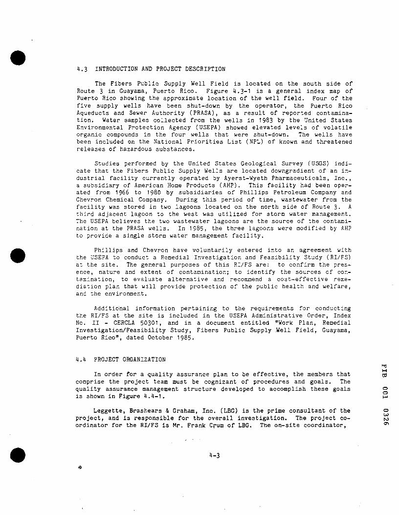
4.3 INTRODUCTION AND PROJECT DESCRIPTION
The Fibers Public Supply Well Field is located on the south side of Route 3 in Guayama, Puerto Rico. Figure 4.3-1 is a general index map of Puerto Rico showing the approximate location of the well field. Four of the five supply wells have been shut-down by the operator, the Puerto Rico Aqueducts and Sewer Authority (PRASA), as a result of reported contamination. Water samples collected from the wells in 1983 by the United States Environmental Protection Agency (USEPA) showed elevated levels of volatile organic compounds in the four wells that were shut-down. The wells have been included on the National Priorities List (NPL) of known and threatened releases of hazardous substances.
Studies performed by the United States Geological Survey (USGS) indicate that the Fibers Public Supply Wells are located downgradient of an industrial facility currently operated by Ayerst-Wyeth Pharmaceuticals, Inc., a subsidiary of American Home Products (AHP). This facility had been operated from 1966 to 1980 by subsidiaries of Phillips Petroleum Company and Chevron Chemical Company. During this period of time, wastewater from the facility was stored in two lagoons located on the north side of Route 3- A third adjacent lagoon to the west was utilized for storm water management. The USEPA believes the two wastewater lagoons are the source of the contamination at the PRASA wells. In 1985, the three lagoons were modified by AHP to provide a single storm water management facility.
Phillips and Chevron have voluntarily entered into an agreement with the USEPA to conduct a Remedial Investigation and Feasibility Study (RI/FS) at the site. The general purposes of this RI/FS are: to confirm the presence, nature and extent of contamination; to identify the sources of contamination, to evaluate alternative and recommend a cost-effective remediation plan that will provide protection of the public health and welfare, and the environment.
Additional information pertaining to the requirements for conducting the RI/FS at the site is included in the USEPA Administrative Order, Index No. II - CERCLA 50301, and in a document entitled "Work Plan, Remedial Investigation/Feasibility Study, Fibers Public Supply .Well Field, Guayama, Puerto Rico", dated October 1985.
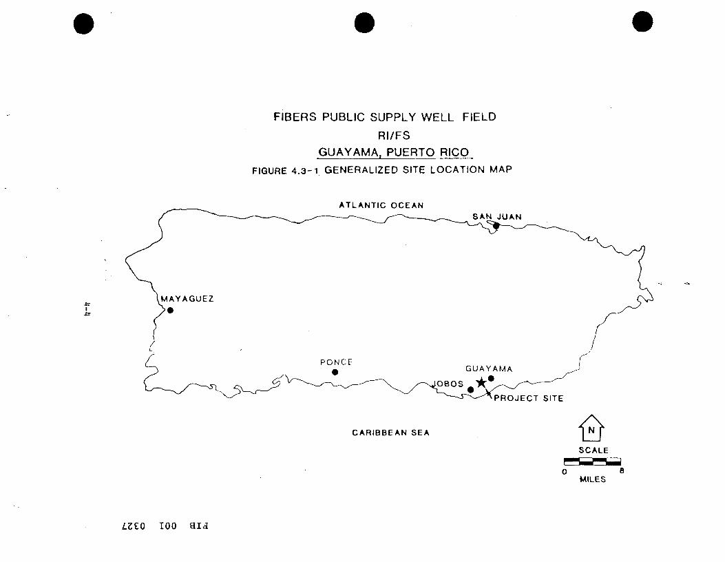
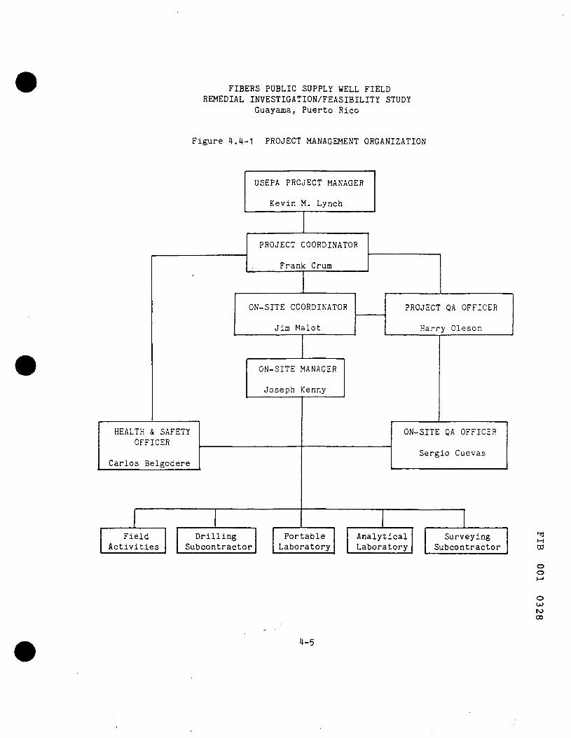
4.4 PROJECT ORGANIZATION
In order for a quality assurance plan to be effective, the members that o3 comprise the project team must be cognizant of procedures and goals. The quality assurance management structure developed to accomplish these goals o is shown in Figure 4.4-1, H"
Leggette, Brashears & Graham, Inc. (LBG) is the prime consultant of the o project, and is responsible for the overall investigation. The project co- to ordinator for the RI/FS is Mr. Frank Crum of LBG. The on-site coordinator, "
4-3
-Jr I
FIBERS PUBLIC SUPPLY WELL FIELD
RI/FS
GUAYAMA, PUERTO RICO
FIGURE 4 .3 -1 GENERALIZED SITE LOCATION MAP
ATLANTIC OCEAN SAN JUAN
PROJECT SITE
CARIBBEAN SEA < ^ SCALE
0 B MILES
LZZO TOO a i d
FIBERS PUBLIC SUPPLY WELL FIELD REMEDIAL INVESTIGATION/FEASIBILITY STUDY
Guayama, Puerto Rico
Figure 4.4-1 PROJECT MANAGEMENT ORGANIZATION
HEALTH & SAFETY OFFICER
Carlos Belgodere
Field Activities
USEPA PROJECT MANAGER
Kevin M. Lynch
PROJECT COORDINATOR
Frank Crum
ON-SITE COORDINATOR
Jim Malot
ON-SITE MANAGER
Joseph Kenny
Drilling Subcontractor
Portable Laboratory
PROJECT QA OFFICER
Harry Oleson
ON-SITE QA OFFICER
Sergio Cuevas
Analytical Laboratory
Surveying Subcontractor
M DO
o o
o u> to 00
4-5

Mr. James J. Malot, of James Malot, P.E. (JJM) will assist LBG in management of project activities conducted in Puerto Rico. Mr. Malot is responsible for local technical activities and will assist in local agency liaison. The on-site manager, Mr. Joseph Kenny (JJM) will be the technical and administrative manager of on-site activities. He will be responsible for coordinating and scheduling on-site investigative efforts.
The QA officer will be Mr. Harry Oleson of LBG. The QA officer responsibilities include the review of QA documentation during the project, and coordination with the on-site QA and Environmental Testing and Certification Laboratory (ETC) QA officers.
The on-site QA officer will be responsible for assuring compliance with QA/QC procedures during field sampling. The duties of the on-site QA officer includes the following:
1. Train field personnel in the proper methods of sampling 2. Ensure that operational QA/QC procedures are in order 3. Oversee the application of calibration methods and maintenance of
calibration records for field monitoring instruments
Mr. Sergio Cuevas (JJM) will be the designated on-site QA officer for the project. In his absence, he or his supervisor(s) may designate a qualified temporary replacement. Such designation will be noted i n the field log.
The ETC QA officer's responsibilities include the duties described in Appendix 4-A, and coordination with the project QA officer and on-site QA officer.
Field personnel will be responsible for understanding the applicable QA/QC procedures and for complying with procedures during all sample collection and testing activities.
4.5 QUALITY ASSURANCE OBJECTIVES
Chemical analyses will be performed on soil and water samples collected during the project. Quality assurance objectives for these analyses, including analytical laboratory, field analyses and field sampling, are described in this section. Ground-water samples and selected soil samples nj obtained during the project will be sent to ETC, in Edison, New Jersey, for ^ chemical analysis. In addition to those analyses, soil and water samples will be analyzed on-site with a portable gas chromatograph (GC) by JJM. o
o
o
to
4-6
4.5.1 QUALITY ASSURANCE OBJECTIVES - ANALYTICAL LABORATORY
Ground-water samples and selected soils samples obtained during the project will be sent to ETC for chemical analysis. The quality assurance objectives established by ETC meet or exceed the EPA Contract lab requirements and are included in Appendix 4-A at the end of this chapter.
4.5.2 QUALITY ASSURANCE OBJECTIVES - FIELD LABORATORY
Precision: The field laboratory objective for precision will be to meet or exceed the precision demonstrated for these analytical methods under similar circumstances.
Accuracy: The field laboratory objective for accuracy will be to equal or exceed the accuracy demonstrated for these analytical methods under similar circumstances.
Representativeness: This is a function of the sampling method used and the procedures for processing the samples. The objective is to demonstrate the degree of quality of the data gathered and the degree to which it represents an environmental condition. It can be determined by a comparison of the quality control data for samples analyzed against other data for similar samples under the same circumstances.
Comparability: The objectives for the field laboratory are to use standard methodology and to apply appropriate levels of quality control. By using standard methodology and QC procedures, the results of the analysis can be compared with other analyses by other laboratories.
Completeness: The objective for the field laboratory is to include sufficient information in the document that will provide the data to assess the quality of the results. Information delivered includes chromatograms, QC data, and tabulation of results.
4.5.3 QUALITY ASSURANCE OBJECTIVES - FIELD SAMPLING
The quality assurance objectives for the field sampling program are to achieve a 90$ level of validated samples in each sample population and a 95$ H
CO compliance with the procedures established to produce noncontaminated samples. o
o
o Ul u» o
4-7

4.6 SAMPLING PROCEDURES
4.6.1 GROUND-WATER SAMPLING - MONITOR WELLS
4.6.1.1 PREPARATION
4.6.1.1.1 DRILLING
1. Drilling activities will be under the direct technical supervision of the on-site manager.
2. Hollow-stem augers will be used for drilling. 3. Hollow-stem augers will be steam cleaned in order to remove debris
or sediment and to minimize cross contamination between boreholes. 4. Steam-cleaned augers and tools will be kept on and covered by
plastic sheeting and not allowed to contact the ground.
4.6.1.1.2 INTEGRITY OF WATER SAMPLING POINTS (SCREEN ZONES)
1. The 2-inch diameter stainless steel screen and casing will be kept in shipping boxes prior to installation. While placing the screen care will be taken to minimize of contact of the screen with borehole wall by using centralizers.
2. The annulus between the well bore and the well screen will be filled with silica sand approximately to 3 feet above the top of the screen.
3. A 2-foot thick bentonite seal will be installed on top of the sand.
4. A bentonite-cement grout will be placed in the annulus above the bentonite seal to the land surface.
5. A four-inch diameter protective steel casing and locking cap will cover the well casing.
6. A concrete pad will be constructed to direct surface water away from the well.
7. The well will be developed by using an air-lift pump.
4.6.1.2 WATER-SAMPLE CONTAINERS
1. Water samples to be analyzed in the field with a portable GC unit will be collected in pre-cleaned 16 ounce wide-mouth jars with teflon-lined lids and screw caps.
2, Field personnel in charge of sampling will check the sample number nj assigned to each bottle against the sample number on the chain-of-custody from before signing the form.
03
o o
o LO
4-8

3. Water samples collected for shipment to ETC will be collected in sealed, pre-cleaned bottles provided by ETC, Samples requiring preservation will have pre-measured preservatives attached to the bottles when they arrive on site. A standard set of bottles for one water sample is described in Table 4.6-1.
4. Samples for ETC testing will be sent by express courier to the lab.
4.6.1.3 SAMPLE COLLECTION
1 . Measure the static water level in the well with a steel tape or electric probe.
2. Calculate the volume of water in the well from the well depth, the static water level, and the casing diameter.
3. Use steam-cleaned stainless steel bailers that are dedicated to each monitoring well.
4. Bail a minimum of 3 casing volumes from the monitoring wells. If necessary, continue bailing until field measurements of temperature, pH and conductivity stabilize,
5. Collect the sample in a standard set of bottles. 6. Avoid unnecessary turbulence of the water in the collection proce
dure and leave no air space in those bottles for ETC analysis of volatile organics.
7. Containers for portable GC analysis will be filled approximately half full with sample water and sealed.
8. Complete and affix a sample label to each sample container. Cover the label with clear vinyl tape.
9. Complete a chain-of-custody forn before relinquishing the sample to the field laboratory analyst or on-site QA officer.
4.6.2 GROUND WATER SAMPLING - PRASA WELLS & AHP WELL
4.6.2.1 PREPARATION
Prior to sampling, information will be compiled from the PRASA or AHP to obtain relevant information on well size, pump type, yield, well reliability and electrical connections and startup procedures.
Where pumps are set into the wells, those pumps will be utilized for sampling. In those wells without pumps, a portable electrically-powered pump will be installed in the well. Samples will be taken from a point as close to the pump as possible. Provisions for handling the discharge water ^ will be provided, tj
CO
o o M
o w to
4-9

FIBERS PUBLIC SUPPLY WELL FIELD REMEDIAL INVESTIGATION/FEASIBILITY STUDY
Guavama, Puerto Rico
Table 4,6-1 STANDARD SET OF BOTTLES FOR WATER SAMPLES
Bottle Description
l-liter(L) Amber Glass
40-milliliter (ml) Clear Glass
500-ml Amber Glass
125-ml Amber Glass
125-ml Amber Glass
1-L Amber Glass
1-L Plastic
Quantity Analysis
8 Extractable Organics
3 Volatile Organics
Ammonia
Sulfide
Cyanide
Inorganics
Metals
Preservatives
No
No
No
Yes
Yes
No
Yes
Note: All glass bottles to have teflon-lined screw caps.
M DO
o o
o
u> OJ
4-10
4.6.2.2 WATER-SAMPLE CONTAINERS
1. Water samples to be analyzed in the field with a gas chromatograph (GC) will be collected in pre-cleaned 16 ounce wide-mouth jars with teflon lined lids and screw caps.
2. Field personnel in charge of sampling will check the sample number assigned to each bottle against the sample number on the chain-of-custody form before signing the form.
3. Water samples collected for shipment to ETC will be collected in sealed, pre-cleaned bottles provided by ETC. Samples requiring preservation will have pre-measured preservatives attached to the bottles when they arrive on site. A standard set of bottles for one water sample is described in Table 4.6-1.
4. Sample containers for ETC testing will be sent by express courier to the lab.
4.6.2.3 SAMPLE COLLECTION
1. Prior to collection of a sample, the pump will be run until field measurements of the discharge water demonstrate stabilized values of pH, temperature and conductivity. A minimum of 3 well volumes will be removed.
2. When sampling from a water tap or water line, the packing should be tight and aerators must be removed to prevent the loss of volatile organics.
3. The samples will be collected in a standard set of bottles as described in Table ^.6-1.
4. Care will be given to the collection of water sam.ples for volatile. organic analysis. Water should be poured slowly down the side of the vial until it is filled. After filling, the vial should be inverted to ensure that there are no air bubbles. If air bubbles are found, another sample must be taken.
5. Containers for field GC analysis will be filled approximately half full with sample water and sealed.
6. Complete and affix a sample tag to each sample container. For samples that will be shipped to ETC, the tag will be protected with clear vinyl tape.
7. A chain-of-custody form will be signed before the samples are relinquished.
4.6.3 SOIL SAMPLING - SPLIT SPOON SAMPLER
4.6,3.1 DRILLING
o
1, Drilling operations will be under the direct technical supervision of the on-site manager.
2, Hollow-stem augers will be used for drilling. o 3, Split-spoon barrels will be used for sampling the soils at a mini
mum of 5 foot intervals. ^ OJ OJ
4-11

4. Hollow-stem augers and split-spoon barrels will be steam cleaned to remove debris or sediment and to minimize cross-contamination between boreholes.
5, Steam-cleaned augers and tools will be kept on, and covered by plastic sheeting and not allowed to contact the ground.
4.6.3.2 SOIL-SAMPLE CONTAINERS
1. Soil samples to be analyzed in the field with a gas chromatograph (GC) will be collected in precleaned l6-ounce wide mouth jars. Containers for field GC analysis will be filled approximately half full with the soil sample. The jars will be sealed with teflon-lined lids and screw caps.
2. Field personnel in charge of sampling will check the sample number assigned to each bottle against the sample number on the chain-of-custody form before signing the form.
3. Soil samples collected for shipment to ETC will be collected in sealed, pre-cleaned bottles provided by ETC, A standard set of bottles for each soil sample is described in Table 4,6-2, Samples for ETC testing will be sent by express courier to the lab,
4.6.3.3 SAMPLE COLLECTION, SPLIT-BARREL SAMPLER
1. Steam clean the split-spoon sampler before each borehole. Clean gloves must be used whenever handling the sampler.
2. Open the split spoon and discard the top portion of the sample which may represent disturbed soil,
• 3. Handle the sample carefully and quickly in order to avoid losing volatile components,
4. Split the sample in half longitudinally and place one half in the field-analysis sample jar. Cap tightly.
5. The other half of the sample will be placed in a clean sample container and retained for potential ETC analysis. Wash the spatula with soap and water and rinse with distilled water between samples,
6. Complete and affix a sample label to the sample container. Cover the label with clear vinyl tape. Record the information in the sampling log.
7. Return samples to the field laboratory where they will be tested for volatile organic compounds using EPA Method No. 8020 as described in USEPA Manual No. SW-846.
8. Duplicate samples are taken by placing each half of a longitudinally split core in a jar and filling out two sample tags indi- ,^ eating a duplicate sample. M
9. Field blanks are taken by rinsing a steam cleaned split-spoon sampler with distilled water and putting the water in a jar. ^
10. Soil grain-size analysis and other required physical analysis will o be performed by a certified geo-technical firm.
o OJ OJ Ol
M-12

FIBERS PUBLIC SUPPLY WELL FIELD REMEDIAL INVESTIGATION/FEASIBILITY STUDY
Guavama. Puerto Rico
Table 4.6-2 STANDARD SET OF BOTTLES FOR SOIL SAMPLES
Bottle Description Quantity Analysis Preservatives
40-milliliter (ml)
Clear Glass 1 Volatile Organics No
1-Liter Amber Glass 1 Extractable Organics
Inorganics Metals Sulfide Cyanide Ammonia No
500-ml Amber Glass 1 TCDD (Dioxin) No
Note: All glass bottles to have teflon-lined screw caps.
M ro
o o
o OJ OJ
4-13

4.6.4 SAMPLE COLLECTION, SHELBY TUBE SAMPLER
1. All thin-wall tube sampling shall be performed in accordance with ASTM D-1587.
2. The sampler and Shelby Tubes shall be steam cleaned prior to use, and the tubes inspected to assure that they are true to roundness. The dimensions . of the tube shall be in accordance with ASTM D-1587.
3. The Shelby-Tube head shall be in good working order including the plunger, water port and check valve.
4. When collecting samples, the sampler will be pushed without rotation and at a rate not to exceed 1 inch/2 seconds. The length that the sampler is pushed and the actual length of the sample shall be recorded and this information used to calculate the percent recovery at the sample.
5. Record the sample at the depth interval that the sampler was pushed.
6. Each sample must be handled with extreme care to assure that it is in its natural state.
7. Remove the tube from the sampling head. 8. Measure and record the length of the sample contained inside the
tube. 9. Remove 1 inch of soil from both ends of the sample. This can be
accomplished using the tool described in ASTM D-1587. 10. Clean the insides of the tube where the soil was removed so that
the open end sections of the tube are clear of soil particles. 11. Fill the .bottom of the open ends of the tube 1/2 the way full with
molten wax and allow to harden. 12. Fill the remaining portion of both the open ends of the tube with
molten wax and allow to harden. Inspect both ends for voids or cracks in the wax plugs; if cracks or voids are observed, remove 1/2 inch of wax and repeat step 7.
13. Wrap both ends of the tube tightly in cheese cloth and dip into molten wax sufficient times to accumulate a 1/4 inch coating on both ends of the tube.
14. Label the tube in two separate locations with date, project, sample number, depth interval and boring/well number. Labeling will be accomplished with an indelible marker.
15. Store samples in a cool dry location, out of direct sunlight. 16. Note sample number and depth interval sampled on boring log.
"3 H Cd
o o
4-14
o oJ
4.6.5 SURFACE-WATER SAMPLING PROCEDURES
Field procedures for sampling surface waters are as follows:
1. The Guamani River and surface waters north and south of the site that indicate interaction with the ground waters at the site will be sampled.
2. Sainples collected for field analysis will be placed in 16 ounce wide-mouth jars. The jars will be sealed with teflon-lined lids and screw caps.
3. Samples collected for shipment to ETC will be collected in sealed, pre-cleaned bottles provided by ETC. Sample containers requiring preservation will have pre-measured preservatives attached to them when they arrive on site. A standard set of bottles for one water sample is described in Table 4.6.1.
4. Samples to be collected in containers with preservatives will not be submerged in the water being sampled. A clean glass bottle will be used to bail water from the stream to place in the sample container.
5. Protective gloves will be used to dip the bottles into the stream. 6. The bail bottle will be submerged upside-down just below the water
surface. The bottle will be inverted slowly to allow it to fill. 7. Bottles that will have preservatives added to them, will be filled
from the bail bottle. 8. For sample collection in bottles and vials without preservatives,
follow the procedure outlined in step 6 using the sample bottle in lieu of the bail bottle.
9. Cap each sample bottle as soon as the sample is collected. 10. Invert the vials containing the samples for volatile organics
analysis to ensure that there are no bubbles in the sample. If bubbles are found, discard that sample and collect another sample.
11. Collect an additional water sample in a clean glass bottle for immediate measurement of temperature, pH and conductivity.
12. Sign a chain-of-custody form before relinquishing the samples. 13. Samples collected for shipment will be shipped via express courier
to ETC. 14. Surface-water samples will be analyzed for the chemicals shown in
Appendix 4-A.
4.6.6 SEDIMENT SAMPLING PROCEDURES
If data obtained during preliminary investigations at the Fibers site indicates that the quality of water at the Guamani River has been affected by the plant site, sampling of the sediments from the river will be undertaken, ^
•
o o
o OJ OJ 00
4-15
Equipment needed to carry out t h i s a c t i v i t y includes:
a. Gravity corer b. l6-ounce wide mouth jars c. Teflon-lined lids and screw caps d. Standard sets of bottles e. Stainless-steel lab spoon g. Protective gloves
The procedure for sampling sediments is shown below:
1. Sampling of the Guamani River sediments will be undertaken if verification of the ground-water flow directions indicate the potential for interaction with the surface-water system at the site.
2. Sediment samples will be placed in sealed, pre-cleaned 16 ounce wide mouth jars. Only one jar will be required for each sample.
3. A gravity corer will be used the collect the sediment samples. 4. A pre-cleaned corer will be attached to the required length of
sample line. The free end of the line will be secured to a fixed support to prevent accidental loss of the corer. The corer will be dropped freely to fall through the liquid, and retrieved with a smooth, continuous lifting motion.
5. Remove the sample from the corer and place into a sample bottle with a stainless-steel lab spoon.
6. Cap jar with teflon-lined lid and screw cap. 7. A sample .label will be completed and affixed to the jar and
covered with clear vinyl tape. 9. A chain-of-custody form will be signed before relinquishing the
sample to the laboratory for analysis. 10. Sediment samples will be analyzed for the chemicals shown in
Appendix 4-A.
4.7 SAMPLE CUSTODY
The objective of a chain-of-custody procedure is to document the history of each sample, and its handling. Chain-of-custody records are used to trace a sample from collection to final disposition after analysis has been performed. The on-site QA officer is responsible for ensuring that chain-of-custody procedures consistent with Section 1,3 of SW 846 are followed. These procedures include proper completion of sample identification and sample transfer records.
4,7.1 SAMPLE IDENTIFICATION
Sample identification is initiated by the sample collector. A stock of pre-cleaned glass jars with teflon-lined lids will be kept at the field laboratory under custody of the laboratory analyst. o
oo
4-16
M
O o

During sampling activities, the sample collector will affix a sample-identification label to every sample container prior to sampling. The sample identification label will be used to record the information shown on Figure 4.7-1.
The sample numbers assigned will be used on the chain-of-custody records to track each sample from collection to final analysis.
Numbers assigned to each sample will be recorded in the field office sample log as assigned. Information recorded on the sample label by the sample collector will also be recorded in the field office sample log.
4.7.2 SAMPLE TRANSFER PROCEDURES/CHAIN-OF-CUSTODY RECORDS
An individual chain-of-custody form is generated for each sample. The sample collector has the responsibility for the initial step in the chain-of-custody command. On returning a sample to the field laboratory, the collector will sign a chain-of-custody record as having relinquished the sample. The laboratory analyst will sign the form as receiving the sample and will enter the time and date of acceptance before proceeding with analysis.
The on-site QA officer is responsible for rechecking the sample tags against the chain-of-custody forms and entering the information from the sample-identification tags into the field office sample logs. A chain-of-custody form is shown on Figure 4.7-2. The on-site QA officer is also responsible for confirming the date of analysis and recording it in the sample logs.
4.8 FIELD CALIBRATION PROCEDURES AND FREQUENCY
4.8.1 CALIBRATION PROCEDURES AND FREQUENCY - ON-SITE GAS CHROMATOGRAPH
The calibration procedures as well as analytical procedures conducted by JJM are given in Appendix 4-B at the end of this chapter.
4.8.2 CALIBRATION PROCEDURES AND FREQUENCY - FIELD SAMPLE COLLECTION
Instruments for measurement of pH, temperature and conductivity are calibrated at the beginning of each sampling day or more frequently when a change in testing conditions occurs.
M
o o
o OJ
o
4-17

FIBERS PUBLIC SUPPLY WELL FIELD REMEDIAL INVESTIGATION/FEASIBILITY STUDY
Guavama. Puerto Rico
Figure 4.7-1 SAMPLE IDENTIFICATION LABEL
Sample No.
Location
Project Name
Date Time
Sample Type
Collector
pH Temperature
Conductivity (umho/cm)
Comments:
M
ro
o o
o OJ
4-18
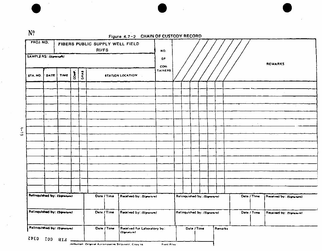
N9
I
>J3
i ^ .
PROJ. N O .
Figure 4 . 7 - 2 CHAIN OF CUSTODY RECORD
FIBERS PUBLIC SUPPLY WELL FIELD
RI/FS
S A M P I X R S : t S i f — n t ^ t
STA. NO. r
O A T l riue 1 —
< K
R«t lnqu l i * tM l b y : IV0»» t t i n i
R i l l n q u l t b M l b y : t n ^ ^ t y n i
R * l l n q u M \ « d b y : IStpnmtvn
ZPZO 100 a i j J
>f
I r l hu t oo (
STATiQM LOCATIOM
D l t « / ' T I m t
D « t t / T i m *
Oat«
Vl» (n» l A f r o
/ T l m «
r*lO*^l*« 3
NO.
OF
CONTAINERS
R*c * l v *d b y : t s i §n tnm l
n t « l v » d b y : i H r t n i n i
R*c« lv*d fo f L a b o f i t o r y b y :
h l p m ^ n l . Cfvfrv IO f i«i<1 f i l l
/m 7/ R E M A R K S
R d i n q u i i h v d b y : t s ^ f f n / ^ l
n * l l n q u i i K * d by : f U t n t t i r t t
D i t *
•
rTim*
1
l ^ tm j rV i
0 « t » / T l m «
0*T« t T i m .
R*c*4v«d b y : O J r w ^ '
R t c a i i M l b y : rT'r<«»"«>
The thermometer is pre-calibrated and will be calibrated on site by comparing readings with a second thermometer. The pH meter is calibrated with two premixed buffer solutions. One solution is for pH of 4.0 and another is for 7.0, Instrument readings will be calibrated prior to sampling using these standards. Similarly, a standard solution mixed at 700 micromhos per centimeter will be used to calibrate the conductivity meter readings prior to sampling. All calibration procedures and notes will be maintained in the field laboratory log book.
4.9 ANALYTICAL PROCEDURES
Detailed analytical procedures are presented in Appendix 4-B for the field gas chromatography analysis. Other field instruments are direct-readout instruments requiring the water sample to be in direct contact with the measuring probe.
Laboratory analysis by ETC will comply with EPA Contract Lab protocols shown in Appendix 4-A.
4.10 FIELD DATA ANALYSIS, VALIDATION AND REPORTING
4.10.1 DATA PRODUCTION
Analytical data are generated from two primary sources: field testir^ and laboratory testing. ETC testing utilizes several instruments (as indicated in Appendix 4-A) to obtain data. Field data is generated by a pK meter, thermometer, conductivity meter and gas chromatograph.
Analytical data generated by the field gas chromatograph includes the graphic output (chromatograms) identification of compounds, concentrations, retention times and comparisons to standards. The field gas chromatograph outputs will be checked manually for accuracy every 100 chromatograms.
Data production also includes internal records available for inspection during audits. These records include the following: laboratory notebooks, log book, worksheets, standards, records and associated quality-control data. A complete record of each sample's history will be available to document the progress from the field through laboratory analysis.
Steps and checks used to validate the precision and accuracy of the analytical work performed and to support its representativeness, comparability and completeness include:
M ro
o o
o OJ
OJ
4-20
• 1. Documentation of analytical and QC/QA methodology. 2. Description of the controls for interference contaminants (use of
reference blanks and check standards for method accuracy and precision) .
3. Description of the calibration of methods and instruments.
4.10.2 DATA VALIDATION
Validation of the analytical data will include review of the following:
1. Contaminants in lab blanks and field blanks. 2. Agreement between samples and duplicates.
Levels of contaminants in lab blanks must be low enough so as not to have an impact on the validity of the data. If contaminants are found in significant levels in one of the field blanks, the sample data will be reviewed to determine if comparable levels are found in other samples obtained that same day. The data will also be grouped to determine any effect the sampling team or equipment may have had in its overall validity.
The mean and standard deviation for each measured parameter for all samples will be calculated as an aid in identifying anomalous values. Spatial plots will be made to aid in detecting similarity in patterns.
4.10.3 DATA REDUCTION
Data reduction includes computation of summary statistics and their standard errors, confidence intervals, test of hypothesis relative to the parameters and model validation. Documentation of this process will be provided.
4.10.4 DATA REPORTING
Data will be reported in both tabular form and in spatial plots. The on-site QA officer will conduct a review of all completed sample data. A review of the data includes:
1. Verification that there are no contaminants in associated blanks 2. Comparison of samples and duplicates for matches in data results 3. Review of all data to make sure they are within acceptable quality
limits
M ro
o o
o OJ
4-21
4.11 FIELD PERFORMANCE AND SYSTEM AUDITS
4.11.1 FIELD SAMPLING SYSTEM AUDIT
The on-site coordinator will conduct a system audit prior to the first day of sampling. EPA may elect to observe this audit or conduct their own.
A system audit will include, but not be limited to the following:
1. Organization and Responsibility - Is the quality assurance structure operational?
2. Sample Collection - Are field personnel adequately trained? Are there any written procedures on sampling? Are they followed?
3. Operational Procedures - Is quality assurance implemented in the field?
4. Chain of Custody - Is the sample collection following the appropriate steps? Are records maintained of all chain-of-custody transfer operations?
5. Equipment - Is the equipment available and in working order? 6. Records - Are records being generated of all field operations? 7. Corrective Action - Is the appropriate chain-of-command followed
in responding to out-of-control situations? 8. Health and Safety - Are proper precautions taken to protect all
field personnel during field operations? Are contingency plans written and understood by all field personnel?
4.11.2 PERFORMANCE AUDITS - FIELD SAMPLING
Procedures for providing blanks and duplicate samples have been established for assessing data precision and accuracy as noted in Appendix 4-B, Section 4-B,8. These procedures offer the opportunity for a performance audit to assure field procedures are followed correctly.
4,12 FIELD ANALYTICAL EQUIPMENT - PREVENTIVE MAINTENANCE
The following is a list of preventive maintenance procedures performed on the field gas chromatograph:
1, Re-conditioning the column to eliminate impurities, 2, Changing septa frequently at the injection port, 3, Cleaning the Flame Ionization Detector, 4, Inspecting syringes to ensure that they are clean and unclogged, ^
o o
o Co
4-22

4.13 SPECIFIC PROCEDURES TO ASSESS DATA PRECISION, ACCURACY AND COMPLETENESS
Assessments of data precision, accuracy, and completeness will be made by ETC during the analysis of all samples sent to the lab. The methods utilized for making these assessments are included in Appendix 4-A.
Each measurement procedure, system, or instrument has predetermined limits to indicate when corrective action is required. ETC monitors their QC data to assure that it is within EPA Contract Lab limits.
Procedures designed to determine field sampling accuracy for laboratory analysis by ETC are to include one trip blank per shipment, one field blank per sample media and one duplicate sample. The blanks will permit the identification of compounds that may have been introduced during sampling or en-route to the lab.
Duplicate samples will be used in order to measure precision of field operations. This can be determined in terms of the Relative Standard Deviation.
RSD = s / X where: s = standard deviation X = Mean of the duplicate samples
4.14 CORRECTIVE ACTION AND FEEDBACK
Whenever a problem in sampling or analysis occurs, a corrective-action sequence is followed. This procedure is illustrated by the flow chart in Figure 4.14-1. To initiate action, a corrective-action request form is submitted to the on-site QA officer. An example of the corrective-action request form is reproduced in Figure 4.14-2. The on-site QA officer will be responsible for follow-up of corrective action requests. The QA officer will also be responsible for follow-up of corrective action requests.
4-23
w
o o
o OJ
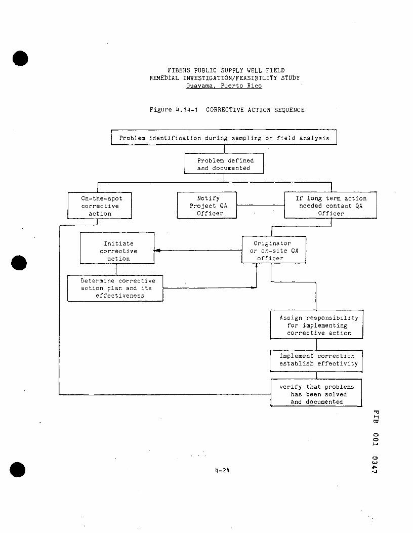
FIBERS PUBLIC SUPPLY WELL FIELD REMEDIAL INVESTIGATION/FEASIBILITY STUDY
Guavama. Puerto Rico
Figure 4.14-1 CORRECTIVE ACTION SEQUENCE
Problem identification during sampling or field analysis
On-the-spot corrective
action
Initiate corrective
action
Determine corrective action plan and its
effectiveness
Problem defined and documented
Notify Project QA Officer
If long term action needed contact QA
Officer
Originator or on-site QA
officer
Assign responsibility for implementing corrective action
Implement correction establish effectivity
verify that problems has been solved and documented
H ro
o o
4-24
o OJ
FIBERS PUBLIC SUPPLY WELL FIELD REMEDIAL INVESTIGATION/FEASIBILITY STUDY
Guavama. Puerto Rico
Figure 4.14-2 CORRECTIVE ACTION REQUEST FORM
Originator: Date:
Reply by: Position:
Problem Identification (to be completed by originator)
a. Nature:
b. Cause:
Signature:
c. Solution:
QA Officer:
M ro
o o
o OJ
CO
4-25
4.15 DOCUMENT CONTROL
The on-site manager will maintain control for all documents passing through project operations at the site. He will also function as a document-control officer and will be responsible for issuing and maintaining records of controlled documents. At the conclusion of all field activities, controlled documents and records shall be delivered to the on-site coordinator. All documents will be copied and forwarded to the project coordinator for overall project document inventory.
M
ro o o
o OJ
4-26

ETC ENVIRONMENTAL TESTING ana CERTIFICATION
LABORATORY QA PROJECT PLAN
FIBERS PUBLIC SUPPLY WELLS SITE
GUAYAMA, PUERTO RICO
prepared for
Leggette, Brashears & Graham. Inc. 1211 North Westshore Boulevard
Suite 510 Tampa. Florida 33607
prepared by
Environmental Testing and Certification Corporation 284 Raritan Center Parkway
Edison, NJ 08818-7808
LaWratory QA Manager M
ro o o
o OJ on o
4A- 1
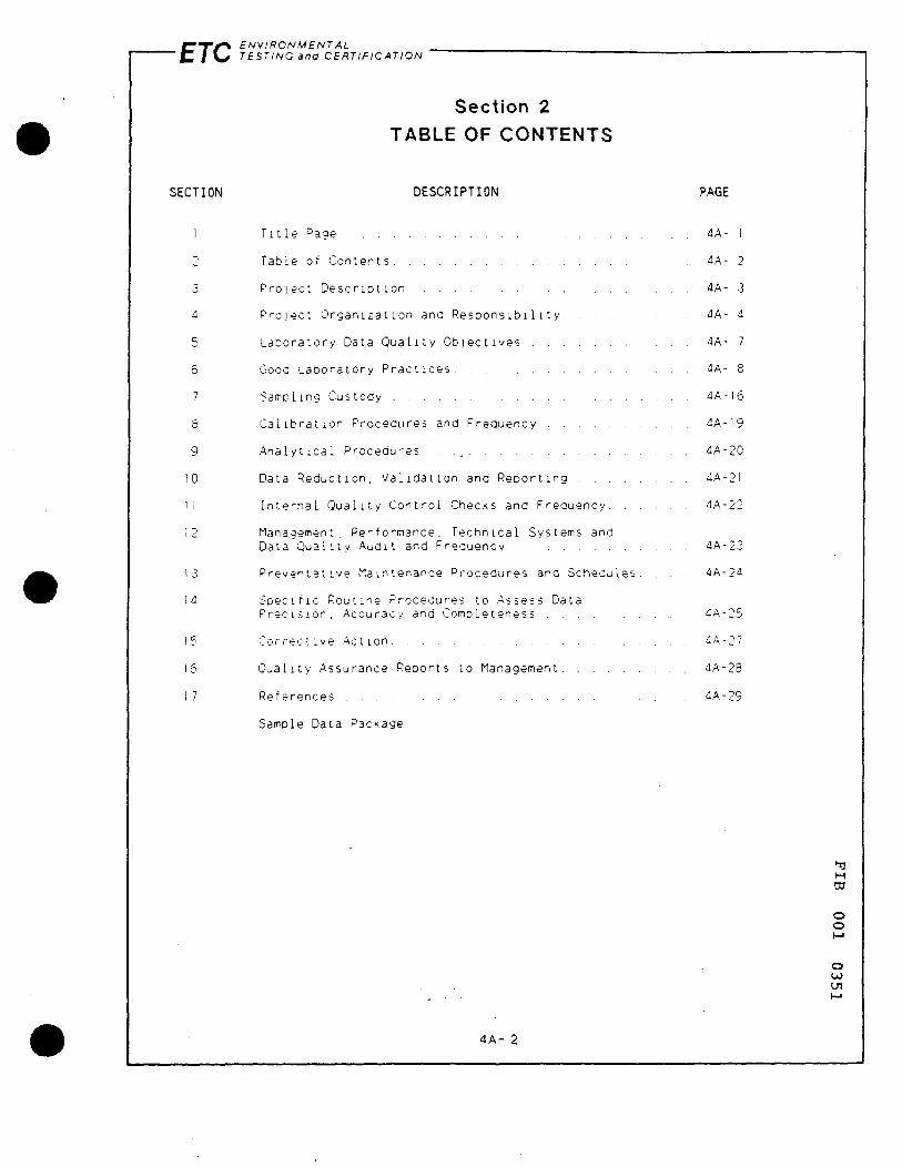
C T / ^ ENVIRONMENTAL C I \ ^ r£Sr;/VG and CERTIFICATION
Section 2
TABLE OF CONTENTS
SECTION DESCRIPTION PAGE
1 rule Page 4A- I
2 Table of Contents 4A- 2
3 Project. Description 4A- 3
4 Project Organization and ResDons ibi 111. y 4A- 4
5 Laboratory Data Quality Objectives 4A- 7
6 Good Laboratory Practices 4A- 8
7 -Samoling Custody 4A-16
8 Calibration Procedtires and Frequency 4A-I9
9 Analytical Procedures. . ., 4A-20
10 Data Reduction, Validation and Reporting 4A-21
11 Internal Ouality Control Checks and Frequency 4A-22
12 Management, Performance. Technical Systems and
Data Quality Audit and Freauency 4A-23
13 Preventative Maintenance Procedures and Schedules. . . . 4A-24
14 Specific Routine Procedures to Assess Data
Precision, Accuracy and Completeness 4A-25
15 Corrective Action 4A-27
16 Quality Assurance Reports to Managemisnt 4A-28 I 7 References 4A-29
Sample Data Package
M ro
o o
o OJ on
4A- 2
ETC E N V I R O N M E N T A L TESTING ana C E R T I F I C A T I O N
Section 3
PROJECT DESCRIPTION
This Laboratory QA Project Plan has been prepared to comply with requirements set forth in the Administrative Order pertaining to the Fibers Public Supply Wells near Guayama, Puerto Rico (index No, ll-CERCLA-50301). The purpose of this plan is to enumerate the procedures by which the Environmental Testing and Certif ication Corporation (ETC) will ensure analytical data generated on this project will be of the highest quality possible. The components of this OA Plan include;
1. An effective, routine quality control program to measure and verify laboratory performance:
2. The use of proven or recommended methodologies to meet data quality requirements for accuracy, precision and completeness;
3. Provision tor corrective actions to avoid adverse affect on data quality;
4. Monitoring and assessment of the operational performance of the laboratory on a routine basis including internal and external audits; and
5. Maintenance of complete writ ten documentation of activ/ties associated with sample processing.
M w
O o
o oo (JI to
4A- 3
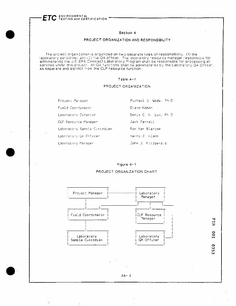
ETC ENVIRONMENTAL TESTING ana CERTIFICATION
Section 4
PROJECT ORGANIZATION AND RESPONSIBILITY
The project organization is organized on two separateJines of responsibil ity; (1) the laboratory personnel, ana \2) tfie OA off icer. Ti-ie laboratory resource manager responsible for administering the U.S. EPA Contract Laboratory Program shall be responsible for processing all samples under this project. All OA functions shall be administered by the Laboratory OA Officer. as separate and distinct from the CLP resource function.
Table 4-1
PROJECT ORGANIZATION
Project Manager
Field Coordinator
Laboratory Director
CLP Resource Manager
Laboratory Sample CListodian
Laboratory QA Officer
Laboratory Manager
Michael J. Wade, Ph.D.
Diane Komar
Denis C. K, Lin, Ph.D.
Jack Farrell
Ron Van Blarcom
Harry J. hlann
John J. Fitzgerald
Figure 4 - 1
PROJECT ORGANIZATION CHART
I I I Project Manager |
I F ie ld Coordinator |
Laboratory | Sample Custodian |
I I I Laboratory | I Manager | I I
ICLP Resource I I Manaaer |
Labor-atory | QA Officer |
M OT
O O
O OJ on OJ
4A- 4
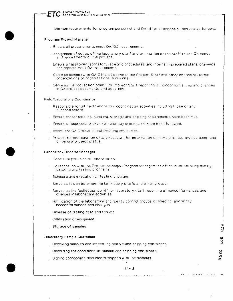
r - T / ^ ENVIRONMENTAL ' i Z I \ ^ TESTING ana CERTIFICATION
Minimum requirements for program personnel and OA off ier 's responsibilities are as fol lows;
Program/Project Manager
. Ensure all procurements meet QA/OC requirements.
. Assignment of duties of the laboratory staff and orientation of the staf f to the OA needs and requirements of the project.
. Ensure all approved laboratory-speci f ic procedures and internally prepared plans, drawings and reports meet QA requirements.
. Serve as liasion (with QA Official) between the Project Staff and other internal/external organizations or organizational sub-units.
. Serve as the "collection point" for Project Staff reporting of nonconformances and changes in QA project documents and activities.
Field/Laboratory Coordinator
. Responsible for all f ie ld/ laboratory coordination activit ies including those of any subcontractors
. Ensure proper labeling, handling, storage and shipping requirements have been met.
. Ensure all appropriate cham-of -custody procedures have been fol lowed.
.. Assist the OA Official in implementing any audits.
. Provide for coordination of any requests for information on sample status, invoice questions or general project status.
Laboratory Director/Manager
. General supervision of laboratories
. Ccllacoration with the Project Manager/Program Management off ice m establishing quality sarroiing and testing programs.
. Schecule and execution of testing program.
, Serve as liasion between the laboratory s taf fs and other groups.
. Serves as the "collection point" for laboratory staf f reporting of nonconformances and , changes in laboratory activit ies.
. Notification of the laboratory anq cuanty control groups of specific laboratory nonconformances and changes
. Release of testing data and results
. Calibration of equipment.
. Storage of samples ^^ ro
Laboratory Sample Custodian Q o
. Receiving samples and inspecting sample and shipping containers. ^
. Recording the conditions of sample and shipping containers. o OJ on
. Signing appropriate documents shipped with the samples. «»
4A- 5

ETC ENVIRONMENTAL TESTING and CERTIFICATION
. Verifying and recording correctness of sample documentation (i.e.. sample tags, chain-of-custody records, billings, etc.)
. Initiate transfer of samples to appropriate lab sections with proper documentation (i.e., lab notebook, assignment sheets, inventory sheets, lab ID number, etc.).
. Placing samples, sample/extracts, and spent samples into appropriate storage and secure areas.
. Controlling and monitoring access and storage of samples/extracts.
QA Officer
. Be the official organizational contact for all QA matters for the project. For example, OA project plan implementation, sampling and analytical methodologies, Data Quality Objectives (DOO's), field and laboratory audits, management and data quality audits, PE and OC studies, etc.
. Actively Identify and respond to OA needs, resolve problems, and answer requests for guidance or assistance. For example, field sampling problems (limited supplies of sample containers), t ransportat ion problems (holding time confl icts), etc.
. Review, evaluate and approve OA project plans prior to EPA review, evaluations and approvai/nonapproval.
. Provide guidance in the development of QA project plans to each respective organization's program of f ices, management off ices and program/program managers or off icers.
. Ensure that management, data quality, field and laboratory audits are performed on QA Project Plans.
. Actively track the progress of all QA tasks in Project Plans (from preplanning to data assessments) and consult periodically with program/project managers.
. Prepare and submit all internal QA reports (with recommendations and comments) to the appropriate line managers m their organization and to EPA officials when properly coordinatec with program/project management.
. Assure that appropriate correct ive actions are taken on all OA tasks when, w.-ere and however needed.
. Ensure that data of known quality and integrity are available for each planning (DOO's) and report phase (valid data).
H W
O o
4A- 6
o oo on on
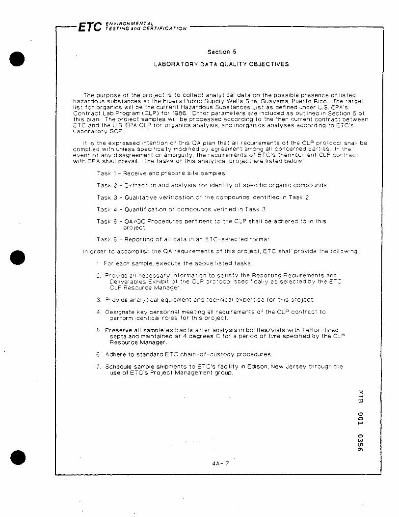
C T ^ ENVIRONMENTAL " C / ^ TESTING ana CERTIFICATION
Section 5
LABORATORY DATA QUALITY OBJECTIVES
The purpose of the project is to col lect analytical data on the possible presence of l isted hazardous substances at the Fibers Public Supply Wells Site, Guayama, Puerto Rico. The target list for organics will be the current Hazardous Substances List as defined under U.S. EPA's Contract Lab Program (CLP) for 1986. Other parameters are included as outlined in Section 6 of this plan. The project samples will be processed according to the then current contract between ETC and the U.S. EPA CLP for organics analysis; and inorganics analyses according to ETC's Laboratory SOP.
It is the expressed intention of this OA plan that all requirements of the CLP protocol shall be complied with unless specifically modified by agreement among all concerned parties, in the event of any disagreement or ambiguity, the requirements of ETC's then-current CLP contract with EPA shall prevail. The tasks of this analytical project are l isted below;
Task 1 - Receive and prepare site samples
Task 2 - Extract ion and analysis for identity of specific organic compounds
Task 3 - Qualitative verif ication of the compounds identified in Task 2
Task 4 - Quantification of compounds verified in Task 3
Task 5 - QA/QC Procedures pertinent to the CLP shall be adhered to in this project
Task 6 - Reporting of all data in an ETC-selected format.
In order to accomplish the QA requirements of this project, ETC shall provide the following;
1. For each sample, execute the above listed tasks.
2. Provide all necessary information to sat isfy the Reoorting Requirements anc Deliverables Exhibit of the CLP protocol soecifically as selected by the ETC CLP Resource Manager.
3. Provide analytical equipment and tecnnical expertise for this project.
4. Designate key personnel meeting all requirements of the CLP contract to perform identical roles for this project.
5. Preserve all sample ex t rac ts after analysis m bot t les/v ia ls with Teflon-lined septa and maintained at 4 degrees 0 for a period of time specified by the CLP Resource Manager.
6. Adhere to standard ETC cham-of -custody procedures.
7. Schedule sample shipments to ETC's facil ity m Edison, New Jersey through the use of ETC's Project Management group.
•fl M
ro
o o M
O OJ
on
4A- 7

ETC ENVIRONMENTAL TESTING ana CERTIFICATION
Section 6
GOOD LABORATORY PRACTICES
ETC maintains a Standard Operating Procedures (SOP) Manual governing the day- to -day laboratory activit ies and methodologies of choice for selected analyses, in addition, the current CLP contract specifies the SOP's level of ef for t required to document the processing of all samples within the CLP resource area. This ef for t should describe the quality assurance and quality control procedures used during analysis. These procedural resources are incorporated herein by reference and shall govern the execution of this project.
The Hazardous Substances List to be employed in this project is reproduced in Table 6-1 exact ly as given m the CLP Document currently in use by U.S. EPA. Although detection limits are strongly matrix dependent, every reasonable ef for t will be made to achieve the listed limit's. The additional parameters are presented in Table 6-2. Respective detection limits for water and soils will be on a best ef for t basis using, currently accepted EPA methodologies.
• f l M W
o o
o oo on
4 A - 8

TABLE 6 - 1
EXHIBIT C
EUzardous S u b s t a n c s Llac (HSL) «nd C o n c r i c t R t q u l r t d D « t t c c l o n L l a l c i (CFJ)L)**
D«t>e t lon L l m l t i *
-1. 2 3. L. 5.
6. 7. 8. 9.-10.
11. ' - 13. U. 15.
16. 17. 13. 19. 20.
21. 22. 23. 24. 25.
Vol*tll«i
Chloroo«ch«n« Brosoa«chan« Vinyl Chlorlda Chloro«ch»n« M«chyltn« Chlorldt
Aceton« Carbon Dlsulfidi L,I-Dichloro«ch«ni l,l-Dlchlorotchan« crans-l, 2-Dlchlo-ro«chene
Chloroform 1,2-Dichloroechane 2-Bucanone 1,1,1-Trichloroechane Carbon Tecrachloride
Vinyl Acetate 3romodlchlorom«th«n« 1,1, 2,2-Tetrachloroethane 1,2-Dichloroprop«n« trans-1,3-Dlchloropropen«
Trichloroeth«n« Dlbroaochloro««chan« 1,1,2-Trlchloro«th*M Benzene cls-1,3-Dlchloroppdpen«
CAS Nuaber
74-87-3 74-83-9 75-01-4 75-00-3 75-09-2
67-64-1 75-15-0 75-35-4 75-35-3 156-60-5
67-66-3, 107-06-2 78-93-3-71-55-6 56-23-5
108-05-4 75-27-4 79-34-5 78-87-5
10061-02-6
79-01-6 124-48-1 79-00-5 71-43-2
10061-01-5
C-1
Low Water'* ug/L
10 10 10 10 5
10
10
10
Low Soil/Sedlier.tS" U8/K«
10 10 10 10 5
10
10
10
(continued)
10/84 Rev
•fl M
W
o o
o oo on 00
4A-9
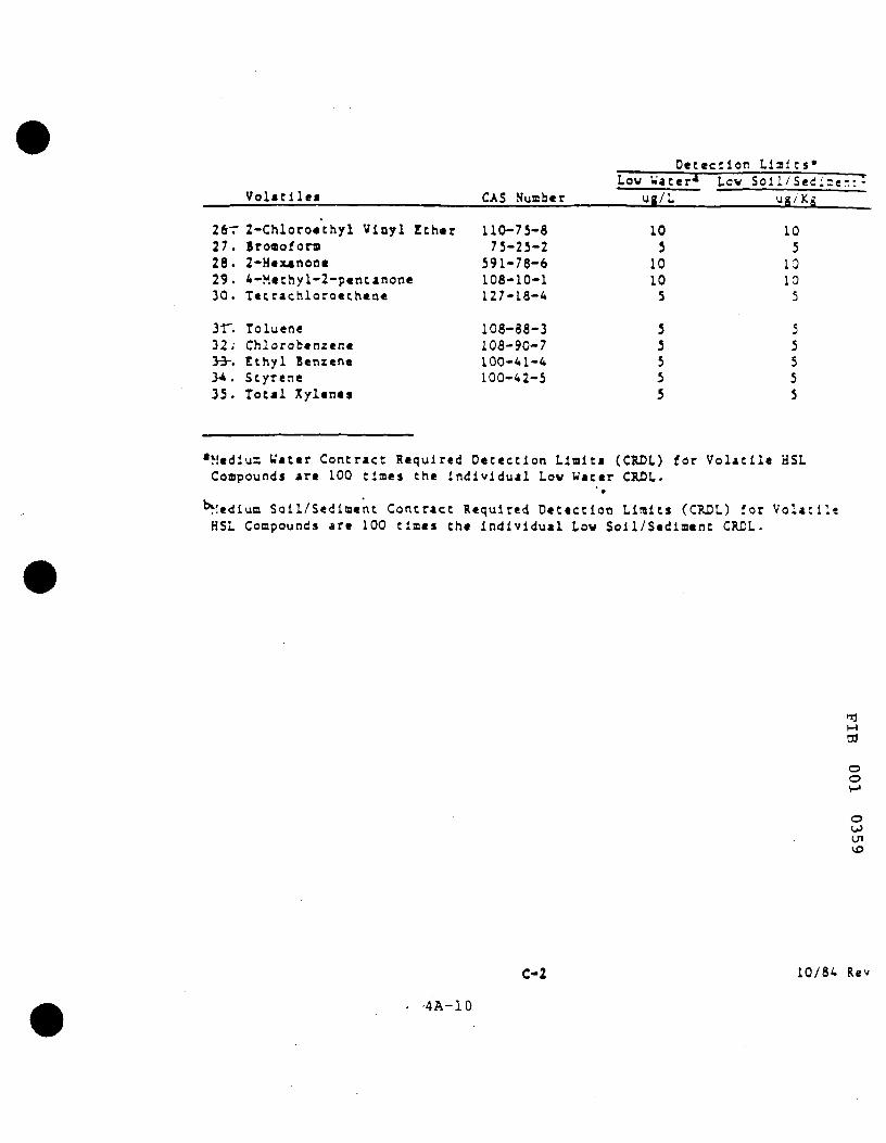
D e t e c t i o n H a l t s *
V o l a t i l e * CAS Nuaber
110-75-8 75-25-2
591-78-6 108-10-1 127-L8-4
108-88-3 108-90-7 100-41-4 100-42-5
Low Water* UR/L
10 5 10 10 5
5 5 5 5 5
Low Soll/Sed:=e-.:-
ug/Ks
10 5 10 10 5
5 5 5 5 5
2frr 2 - C h l o r o « t h y l Viny l E t h e r 27. Broaofora 28. 2-Hexanone 29. 4-Methyl-2-pentanone 30. Tetrachloroethene
31". Toluene 32; Chlorobenzene y^-. Ethyl Benzene >4 . Scyrene 35. Total Xylenes
•Medlus Water Contract Required Detection Llalti (CRDL) for Volatile HSL Compounds are 100 times the Individual Low Vater CRDL.
^lediua Soil/Sediment Contract Required Detection Limits (CRDL) for Volatile HSL Compounds are 100 times the individual Low Soll/Scdlment CRDL.
-fl M
ro o o
o OiJ
C-2 10/84 Rev
•4A-10
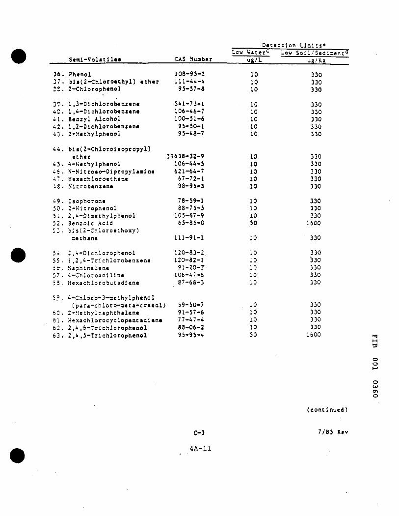
Seml-Volatllee CAS Nuaber
108-95-2 111-44-4 95-57-8
541-73-1 106-46-7 100-51-6 95-50-1 95-48-7
39638-32-9 106-44-5 621-64-7 67-72-1 98-95-3
78-59-1 88-75-5 105-67-9 65-85-0
111-91-1
120-83-2, 120-82-1 91-20-7-106-47-8 87-68-3
59-50-7 91-57-6 77-47-4 88-06-2 95-95-4
Detection Low Water*^ Low
ug/L
10 10 10
10 10 10 10 10
10 10 10 10 10
10 10 10 50
10
10 10 10 10 10
10 10 10 10 50
Limits* Soll/Sedlier.:^
ug/Kg
330 330 330
330 330 330 330 330
330 330 330 330 330
330 330 330 1600
330
330 330 330 330 330
330 330 330 330 1600
36. Phenol 37. bla(2-Chloro€thyl) ether 32. 2-Chlorophenol
3C. 1,3-Dlchlorobenzene 4C. 1,4-Dlchlorobenzene 4 1 . Benzyl Alcohol 42. 1,2-Dlchlorob«Qzen« 43. 2-Methylphenol
44. bli(2-Chlorolaopropyl) ether
45. 4-Kethylphenol 4 6 . N-Nl t ro io -D lp ropy l amlne 47. Hcxachloroethane iS. Nitrobenzene
4 9 . I sophorone 50 . 2-N' l t rophenol 5 1 . 2 , 4 - D l n e t h y l p h e n o l 5 2 . Benzoic Acid 5 3 . b i s ( 2 - C h l o r o e t h o x y )
cethane
54 2,4-Dlchlorophenol 55. 1,2,4-Trlchlorobenzene bt. Naphthalene 57. 4-Chloroanillne 53. Hexachlorobutadlene
;?. 4-Chloro-3-aethylphenol (para-chloro-aeta-cresol)
60. 2-Methylnaphthalene 6-1 . Hexachlorocyclopentadiene 62. 2,4,6-Trichlorophenol 6 3 . 2 , 4 , 5 - T r i c h l o r o p h e n o l 95-95-4 50 1600 n
M
w
o o h J
o O J <T> O
( c o n t i n u e d )
C-3 7 /85 Rev
4 A - 1 1

Sea l -Vo la t i l e s CAS Number
91-58-7 88-74-4
131-11-3 208-96-8 99-09-2
83-32-9 51-28-5
100-02-7 132-64-9 121-14-2
606-20-2 84-66-2
7005-72-3 86-73-7
100-01-6
534-52-1 86-30-6
101-55-3 113-74-1 87-86-5
85-01-8 120-12-7'-84-74-2
206-44-0
129-00-0 85-68-7 91-94-1 56-55-3
117-81-7
218-01-9 117-84-0 205-99-2 207-08-9 50-32-8
Detection Ll=l:s« Low Water"^ Low Soli/Sec:
ug/L ug/Ki
10 330 50 1600 10 330 10 330 50 1600
10 330 50 1600 50 1600 10 330 10 330
10 330 10 330
10 330 10 330 50 1600
50 1600 10 330 10 330 10 330 50 1600
10 330 10 330 10 330 10 330
10 330 10 330 20 660 10 330 10 330
10 330 10 330 10 330 10 330 10 330
z t - z
•n
ro o o M
o OJ ON 1—I
64. 2-ChIoronaphthalenc 65 . 2-Mit roaa i l ine 66 . Dimethyl Ph tha la te ^ 67 . Acaaaphthyleoe 68 . 3 -Nl t roaa l l i ac
-69". Acenaphthene' 70. 2,4-Dinitrophenol 71. 4-Nltrophenol 72 . Dibenzofuran 73. 2,4-Dlnitrotoluene
74 . 2 ,6-Dlnitrotoluene 75. Diethylphthalate 76. 4-Chlorophenyl Phenyl
ether 7^. Fluorene 73. 4-Nitroanlllne
79. 4 ,6-Dinitro-2-aethylphehol 80. N-nltrosodlphenylaalne 81. 4-8roBophenyl Phenyl ether 8 2 . Hexachlorobenzene 83. Pentachlorophenol
84 . Phenanthrene 85. Anthracene 36. Di-n-butylphthalate 37. riuoranthene
88, or'
SO, 91, 92,
Pyrene Butyl Benzyl Phthalate 3,3'-Dlchlorobenzidlne Benzo(a)anthracene bl«(2-ethyIhexyl)phthalate
93. Chrysene 94. Dl-e-octyl Phthalate 95. B«nxo(b)fluoranthene 96. B«nso(k)fluoraathene 9^. &«nzo(a)pyrene
C-*
(continued;
7/85 Rev
4A-12
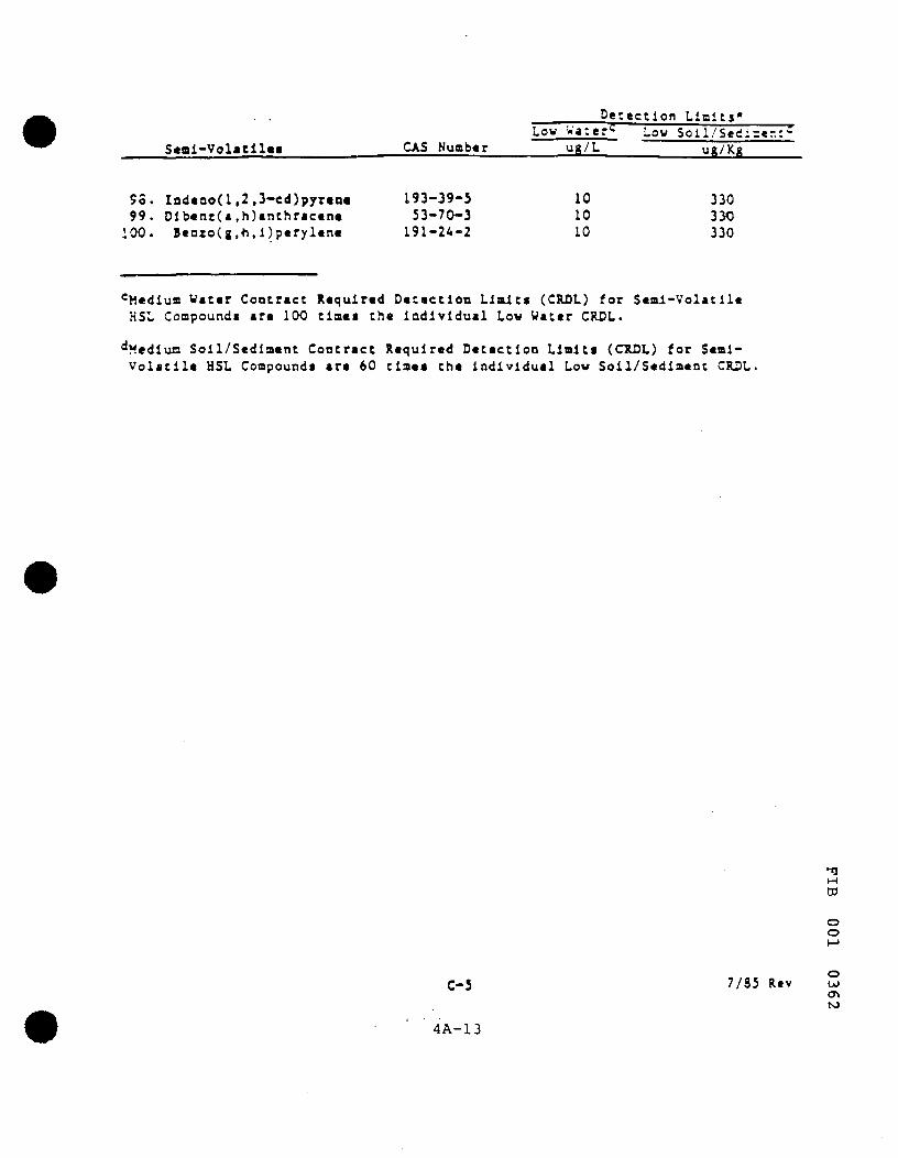
. . . Detection Limits* Low Watef^ Low Soll/Sed:=«r.:-
Seai-Volatllee CAS Nuaber ug/L ug/Kg
53. Indeno(l,2,3-cd)pyren« 193-39-5 10 330 99. Dlbenz(a,h)anthracene 53-70-3 10 330 .00. Benzo(g,h,i)perylene 191-24-2 10 330
<=Mcdiue Water Contract Required Detection Limits (CRDL) for Semi-Volatile HSL Compounds are 100 times the individual Low Water CRDL.
^ ^ t d i u n Soil/Sediment Contract Required Detection Limits (CTIDL) for Semi-Volatile HSL Compounds are 60 tiaee the individual Low Soil/Sediment CRDL.
•fl M
ro o o
C-5 7/85 Rev OJ
4 A-13

Detection Limits*
•
P e s t i c i d e s
1 0 1 . alpha-BHC 102> b«ta-BHC
1 0 3 . del ta-BUC" 104. gaanu-BHC (Lindane) 105 . H e p t a c h l o r 106 . A l d r i n 107 . H e p t a c h l o r Epoxide
108 . Endosu l fan I 109 . D l e l d r l n 110. 4,4 '-DDE 1 1 1 . Endr in 112. Endosul fan I I
113 . 4,4'-DDD 114. Endosu l fan S u l f a t e 115 . 4,4 '-DDT 116. Endr in Ketone
117. Methoxychlor 118 . Chlordane 119. Toxaphene 120. AilOCLOR-1016 1 2 1 . AROCLOR-1221
122. AROa.OR-1232 123 . AROCLOR-1242 124. AROCLOR-1248 125 . AROCLOR-1254 126. AROCLOR-1260
CAS Number
319-84-6 319-85-7
319-86-8 58-89-9 76-44-8
309-00-2 1024-57-3
959-98-8 60 -57-1 72-55-9 72-20-8
33213-65-9
72-54-8 1031-07-8
50 -29 -3 53494-70-5
72-43-5 57-74-9
8001-35-2 12674-11-2 11104-28-2
11141-16-5 53469-21-9 12672-29-6 11097-69-1 11096-82-5
Low Water* uft/L
0.05 0.05
0.05 0.05 0.05 0 .05 0.05
0.05 0.10 0.10 0.10 0.10
0.10 0.10 0 .10 0.10
0 .5 0.5 1.0 0 ,5 0 .5
0 .5 0 .5 0.5 1.0 1.0
Low S o l i / S e c i ^ e -ug/:<;
8 .0 8.0
8.0 8.0 8.0 8.0 8.0
8.0 16.0 16.0 16.0 16.0
16.0 16.0 16.0 16.0
80 .0 80 .0
160.0 80 .0 80 .0
80 .0 80 .0 80 .0
160.0 160.0
'Medium Water Contract Required Detection Limits (CRDL) for Pesticide HSL Compounds are 100 tia«a the indlviduAl Low Water CRDL.
^Hedlua Soll/S«dla«ac Coccract Required Detection Llalts (CRDL) for Pestlclcie HSL coapounda * f 15 tl^s the Individual Low Soll/Sediaent CRDL.
*0«teccloo Halts listed for soil/sediaent are based on wet weight. The derec-tloo Halts calculated by the laboratory for soil/sedlaent, calculated or. dry welchc basis, as requl/red by the contract, will be higher.
** Specific detection Halts are highl^ matrix dependent. The detection Halts listed herein are provided for guidance and aay not always be achievable.
C-6
•fl M ro o o
7/85 Rev
4A-14 o
OJ
OJ

ETC ENVIRONMENTAL TESTING and CERTIFICATION
Table 6-2
A d d i t i o n a l Parameters
PARAMETER
2,3,7,8-TCOO Al, Cr, Ni Ag, Cu, Pb As, Co, Sb Be, Fe, Se Ba, Mg, Sn B, Mn, Ti Ca, Mo, V Cd, Na, Zn Th Hg Ammon18 Sulfide Cyanide TDS Carbonate Bicarbonate Potassium Sulfate Chloride Specific Conductance
MATRIX WATER
X X X X X X X X X X X X X X X X X X X X X
SOIL
X X X X X X X X X X X X X X-
X X
«3
ro
o
o OiJ
4A-1S

ETC ENVIRONMENTAL TESTING and CERTIFICATION
Section 7
SAMPLING CUSTODY
ETC Shall provide all g lassware, appropriate preservat ion, shipping containers and coolant for maintenance of protocol sample preservat ion repuirements for the field sampling event(s). All containers, glassware, etc. shall be under cham-o f -cus tody begun m ETC's Sample Management resource center at the Edison, New Jersey faci l i ty. ETC shall coordinate shipment of i ts Sample Shutt les with the field cont ractor . It will be the responsibil i ty of the designated field contractor to preserve the cham-o f - cus tody through all field activi t ies and to return the ETC-provided Sample Shuttles via an overnight air express such as Federal Express stil l under the cham-o f -cus tody requirments.
ETC will provide all the necessary forms to properly col lect field data and document samole col lect ion. Figure 7-1 provides an example of ETC's CC-1 (Cha in -o f -Cus tody) Form. All of the required information is provided on this form to document sample possession from col lect ion to analysis, including:
. unique sample code
. inventory of Shuttle contents
. sample container pre- labeled to prevent misidentif ication
. project faci l i ty code
. space for sample point i.d.
. sample type
. number of containers and parameters to be analyzed
. cham-o f -cus tody h is tory with signatures, dates and times of possession.
Figure 7-2 provides an example of ETC's CC-2 (Field Parameter) Form, it is oossible io col lect a variety of field data including well purging and sampling information, fieio measureir.ents. field comments and col lector 's signature.
Each of these forms will be provided for each sample to be col lected from each sample comt. It IS the responsibil i ty of pro ject personnel to compile a listing of field data required, it is me responsibi l i ty of the field cont rac tor to col lect such data using the ETC-provided forms, it is the responsibi l i ty of the field cont rac tor to deliver to ETC the properly completed CC- l and CC-2 forms. It IS the responsibi l i ty of ETC to then complete the cha ln -o f - cus tody program using appropriate laboratory chronicles and to provide documentation of all appropriate information m the final report.
• f l M
ro
o o
o OJ
on
4A-16
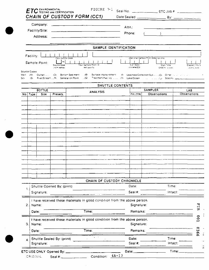
ENVIRONMESTAL TESTING and CERTIFICATION
FIGURE r-1 ETC CHAIN OF CUSTODY FORM (CC1)
Seal No.
Date Sealed
ETC Job#
By: _
Company:
Facility/Site:
Address:
Attn.;
Phone:
SAMPLE IDENTIFICATION
Facility:
Sample Point:
Faci i i i y 'S. ie Cooe
I i - l I I I I I I I
. lOoi ionai Samoie Oomi Oescr iDi ions i
Sou 'ce Code l l r om DelOwl
Youf Samoie Pomt ID
i iet t l us i i f y i
S ian Date
iYY;MW/OD) S i a n Time
i2'iOO nr c ioc» i
Source Codes: Well tWl Outfall (0) Bottom Sediment . . . .(B) Surface impounament .(I) Leacnate Collection Sys (Cl Oiner Soil iS) River/Stream, .iR) Genefation Point . .(G) Treatment Facility . . . . (T) Lake/Ocean I D Soecify
= !apsec -c>,-s
SHUTTLE CONTENTS
BOTTLE
No Type
i i
1
j
Size Preserv. ANALYSIS
SAMPLER Fill. (Y/N) Observations
j
j
(
LAB Observations
1 Shuttle Opened By: (print)
Signature:
CHAIN OF CUSTODY CHRONICLE
Date:
Seal #:
Time:
Intact:
ETC USE ONLY Opened By:.
CSIGiMAL Seal #:
Date:
2.
3.
4.
1 have received these materials in good condition from the above person. Name: Signature:
Date: Time: Remarks:
1 have received these materials in good condition from the above person. Name: Signature:
Date: Time: Remarks:
Shuttle Sealed By: (print) ' Date: Signature: Seal #:
Time: Intact:
OT
O o
o OJ
Time:
Condit ion: 4 A - 1 7

C ^ f ^ ENVIRONMENTAL p . ^ , , p _ ^ _ ^ C 1 \ ^ TESTING and CERTIFICATION F I G U R E 7 2
F/ELD P>\/?>»/Vf£T£fl FO«M (CC2)
ETCJOR#
Sample Point 1 1 1 1 Sourcs Code
1 1 1 1 1 1 1 1 1 ; Sample **aint i.O. ;
FIELD PROCEDURES
I I I I I I PURGE DATE (YY M M DO)
SAMPLING METHOD:
Sampler Type
START PURGE 12400 Hr Clock!
ELAPSED MRS I I I
WATER V O L IN CASING (Gal lonsi
VOLUME P-JRGED i G a i i o n j i
A-Submersible Pump D-Dipper/Bottle 8-ISCO E-Balier C-Bladder Pump F-Scoop/Shovel
Sampler Material
Tubing Material
A-Teflon B-Metal
A-Teflon BTygon
C-PVC D-Plastic
C-Polyetfiylene D-Slllcon
X-Other
X-Other
X-Othet
(SPECIFY OTHESl
(SPECIFY OTr-E.R)
(SPECIFY OTHESl
Sample Composited | Y/N Procedure 'Propor t ions
Well Elevation (ft/msl)
Depth to Ground water (ft)
Groundwater Elevation (ft msl)
FIELD MEASUREMENTS
_ l 1 I I Well Depth (ft)
Sample Depth (non-well) (ft) ' 1
i 1
i i
1st I
2nd I
3rd I
4th [
ph
ph
(STD)
(STO)
(STD)
1st
2nd
t p * c . cond .
sp *c . cond .
3rd
(STD) 4 l h
! CC)
sp«c. cond .
um/cm at 25" C
um/cm atZS'C
um/cm al25*C
um/cm atZS'C
{ o t h « r p a r i m « t « 0
(other parameter)
(other parame leo
value
1 I
valu*
1 i
vatu*
(other parameter)
N T U
Sample Temp T u r t j i d i t y
FIELD COMMENTS
Sample Appearance:.
Weather Condi t ions: .
Other.
M
ro
o o
o O J
FILTERING: Use Chain of Custody (CC1) to indicate which bottles were filtered
Sampler: (PrintI
1 certify that
lOatel
sampling procedures were in
(Signature)
Fmnlovpr ,, • - . 1
accordance with applicable EPA state and corporate protocols. \
4 A - T.8

C T / ^ BNVIRONMENTAL C I K f TESTING ana CERTIFICATION
Section 8
CALIBRATION METHODS AND FREQUENCY
The U.S. EPA Contract Laboratory Program as detailed in IFB Soliciation IFB WA85-J644 provides specific calibrating procedures and frequencies in Section B, D. and E of this document. A brief summary and listing of major comments for each f ract ion is included below. For additional details, refer to the above referenced document.
Volatile Organlcs, Base/Neutral and Acid Fractions
1. Initial five point calibration with cont rac t -spec i f ied control limits on selected compounds. Also continuing calibration checks every 12 hours with con t rac t -spec i f ied reject ion materials.
2. GC/MS performance tuning using BFB and DFTPP every 12 hours. Specific Content Criteria must be met before sample analysis.
3. Reagent/Method Blanks every 12 hours for volat i les and once per batch for ext ractables. Surrogate recoveries and target compound contamination s t r ic t ly control led.
4. All samples, blanks, matrix spikes and matrix spike duplicates are for t i f ied with surrogates.
Recoveries must be within cont ract specif ied limits.
5. One sample per 20 samples is used as a matrix spike and duplicate.
6. Aidditional requrements of document control and report ing are required, refer to appropriate sect ion of document.
Pesticide and PCB Fractions
1. Initial linearity and detect ion limit criteria at beginning of contract .
2. Linearity verif ication of four compounds at three levels every 72 running hours.
3. Interspacec calibration checks of all compounds every 5 samples.
4. Fort i f icat ion of all samples, blanks and spiked matrix samples with dibutyl chlorinate
surrogate. Retention shift cr i ter ia and percent recovery required.
5. Breakdown criteria for endrin and DDT on packed column determined.
6. Str ict control of contamination and surrogate recovery m blanks and QC samples.
7. Additional criteria and documentation control as specif ied in above stated document.
Metals/Conventionals
The analytical methods and calibration procedures are standardized throughout the industry. The procedures are well documented in the appropriate methodologies. We have available a copy of our laboratory SOP for review if necessary.
M ro
o o
o OJ OS 00
4A-19

ETC ENVIRONMENTAL TESTING and CERTIFICATION
Section 9
ANALYTICAL PROCEDURES
Volatile Organics. Base/Neutral and Acids, Pesticides and Polychlorinated Biphenyls (Aroc lors)
The EPA CLP provides very detailed procedures for the analysis of specif ic target compounds indicated in Section C as the Hazardous Substance List. These analytical procedures are detailed in Section D-l to D-133. Specif ic report ing requirements and quality assurance are located in Section B-1 to B-58 and E-1 to E-73. respect ive ly . These procedures are incorporated by reference herein. The CLP "Statement ot Work" is available at ETC's home off ice in Edison, New Jersey for review if necessary. We request at least a 24-hour advance noti f icat ion to review these or any other documents so ETC can ensure the appropriate personnel are available.
Metals/Conventionals
The analytical methods and calibration procedures are standardized throughout the industry. The procedures are well documented in the appropr iate methodologies. We have available a copy of our laboratory SOP for review if necessary.
13 M ro
o o
o OJ <Tt VO
4A-20
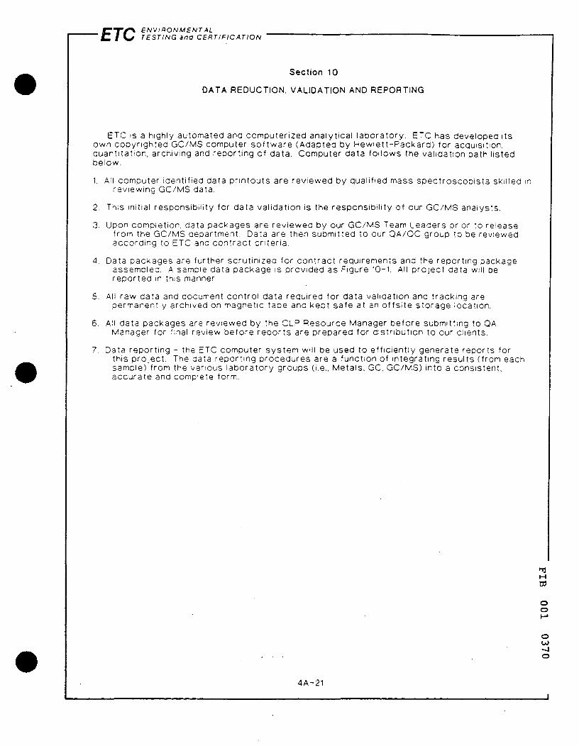
ETC ENVIRONMENTAL TESTING ana CERTIFICATION
Section 10
DATA REDUCTION. VALIDATION AND REPORTING
ETC is a highly automated and computerized analytical laboratory. ETC has developed its own copyr ighted GC/MS computer so f tware (Adapted by Hewlet t -Packard) for acquisition, quantitat ion, archiving and report ing of data. Computer data fol lows the validation path l isted below.
1. All computer identified data pr intouts are reviewed by qualified mass spect roscopis ts skilled in reviewing GC/MS data.
2. This initial responsibil i ty for data validation is the responsibi l i ty of our GC/MS analysts.
3. Upon completion, data packages are reviewed by our GC/MS Team Leaders prior to release from the GC/MS department. Data are then submitted to our QA/QC group to be reviewed according to ETC and contract cr i ter ia.
4. Data packages are further scrut inized for contract requirements and the report ing package assembled. A sample data package is provided as Figure 10-1. All pro ject data will be repor ted in this manner.
5. All raw data and document contro l data required for data validation and tracking are permanently archived on magnetic tape and kept safe at an o f fs i te storage location.
6. All data packages are reviewed by the CLP Resource Manager before submitting to QA Manager for final review before repor ts are prepared for distr ibution to our clients.
7. Data report ing - the ETC computer system will be used to eff ic ient ly generate reports for this pro ject . The data report ing procedures are a function of integrating results (from each sample) from the various laboratory groups (i.e., Metals, GC. GC/MS) into a consistent, accurate and complete form.
M W
O o
o OJ - J o
4A-21
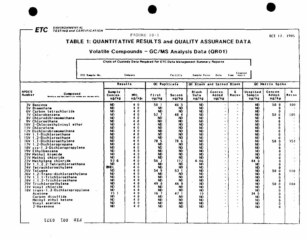
g — r ^ ^ BNVmONMEN C I K ^ TESTING and
TAL Cenr iF ICATION
FIGURi ; 1 0 - 1
TABLE 1: QUANTITATIVE RESULTS and QUALITY ASSURANCE DATA
Volati le Compounds • - GC/MS Anatysis Data (QR01)
Chain ot Cuatody Data Raqukad for ETC Data Management Summary Report*
(TC t J w U No.
NPOES Number Compound
3V Benzene 5V Brof f lo form 6V/ Carbon t e t r a c h l o r i d e 7V/ C h l o r o b e n i e n e 8V C h l o r o d l b r o m o M e t h a n a 9V C h l o r o e t h a n e
lOV 2 - C h l o r o e t h y l v l n y l e t h e r 1IV C h l o r o f o r m 12V O i c h l o r o b r o m o m e t h a n e 14V 1 . 1 - D i c h l o r o e t h a n e ISV 1 . 2 - D i c h l o r o e t h a n e 16V 1 . 1 - D i c h l o r o e t h y l e n e 17V 1 . 2 - D i c h l o r o p r o p a n a ISV c i s - l . 3 - D i c h l o r o p r o p y l e n e 19V E t h y l b e n z e n e 20V M e t h y l b r o m i d e 2 W M e t h y l c h l o r i d e 22V M e t h y l e n e c h l o r i d e 23V 1 , 1 . 2 . 2 - T e t r a c h l o r o e t h B n e 24V T e t r a c h l o r o e t h y l e n e 2SV T o l u e n e 26V 1 . 2 - T r a n s - d l c h l o r o e t h y l e n e 27V l . l . l - T r l c h l o r o e t h a n e 28V 1 . 1 , 2 - T r i c h l o r o e t h a n e 29V T r i c h i o r o e t h y l e n e 31V V i n y l c h l o r i d e ISV t r a n s - l . 3 - D i c h l o r o p r o p y l e n e
A c e t o n e C a r b o n d i s u l f i d e M e t h y l e t h y l ke tone V i n y l a c e t a t e 2 -Hexanone
ILZO TOO a i j
Co«e<oy
R a t u l t t
Sample Concen .
u g / k g
ND ND ND ND ND ND ND ND ND ND ND ND ND ND ND ND ND 93 6 ND
BK)L ND ND ND ND ND ND hC 15 1 ND ND ND ND
HDL u g / k g .
4 0 4 0 4 0 4 0 4 0 4 0 4 0 4 0 4 0 4 0 4 0 4 0 4 0 4 0 4 0 4 0 4 0 4 0 4 0 4 0 4 0 4 0 4 0 4 0 4 0 4 0 4 0 4 0 4 0 4 0 4 0 4 0
1 f . i»p\ta \
F a c l l l l y S a n p l * Po in l 0 < l < 1 law Hau
QC R e p l i c a l a
f i r i t u g / k g
50 1 ND ND
52 7 ND ND ND ND KO ND ND
78 5 ND ND ND ND ND
56 2 ND ND
54 9 ND ND ND
49 8 ND ND
16 7 NO ND ND ND
Second u g / k g
46 5 ND ND
48 4 ND ND ND ND ND ND ND
78 6 hO ND ND ND ND
112 ND ND
53 1 ND ND ND
46 8 ND ND
47 1 ND ND ND ND
OC B lank and S p i k e d B lank
B lank Da ta u g / k g
ND M) ND ND ND ND ND ND ND ND ND ND ND ND ND ND ND
6 66 ND ND ND ND ND ND ND ND rgo 19 ND ND t t i ND
Concen . Added u g / k g
. ------------------------------
"
X Recow
_ ------------------------------
Z-i
OCT 17 .
QC M a t r i H S p l k
Unsp i ked Sample
u g / k g
t t i ND ND ND ND ND ND ND ND ND ND ND ND ND ND NO ND
44 0 ND ND ND NO ND NO NO NO ND
34 0 NO NO NO NO
Concen Added u g / k g
50 0 0 0
50 0 0 0 0 0 0 0 0
50 0 0 0 0 0 0 0 0 0
50 0 0 0 0
50 0 0 0 0 0 0 0 0
1985
»
X Kecov
100 --
105
--
---
157 -
------
110
100
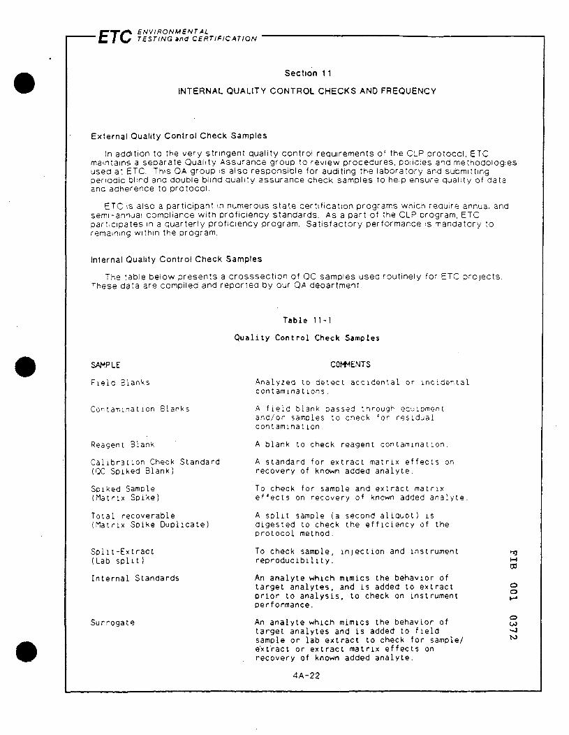
f ^ - r / ^ ENVIRONMENTAL ' C 1 VX TESTING ana CERTIFICATION
Section 11
INTERNAL QUALITY CONTROL CHECKS AND FREQUENCY
External Quality Control Check Samples
In addition to the very str ingent quali ty control requirements of the CLP protocol , ETC maintains a separate Quality Assurance group to review procedures, policies and methodolog used at ETC. This OA group is also responsible for auditing the laboratory and submitting periodic blind and double blind quality assurance check samples to help ensure quality of data and adherence to protocol .
es
ETC is also a part icipant in numerous s ta te cer t i f icat ion programs which require annual and semi-annual compliance with prof ic iency standards. As a part of the CLP program, ETC part ic ipates in a quarter ly prof ic iency program. Sat is fac tory performance is mandatory to remaining within the program.
Internal Quality Control Check Samples
The table below presents a c rosssect ion of OC samples used routinely for ETC pro jects , •^hese data are compiled and repor ted by our QA department.
SAMPLE
P i e l d Blanks
Contamination Blanks
Reagent Blank
C a l i b r a t i o n Check Standard (OC Spiked Blank)
Spiked Sample (Matr ix Spike)
Tota l recoverable (Matr ix Spike Dup l i ca te )
S p l i t - E x t r a c t (Lab s p l i t )
I n t e r n a l Standards
Surrogate
Table 11-1
Q u a l i t y Cont ro l Check Samples
COtt ENTS
Analyzed to de lec t acc iden ta l or i n c i d e n t a l contaminat ions .
A f i e l d blank passed through eauipment and/or samoles to check for res idua l con tamina t ion .
A blank to check reagent contaminat ion .
A standard for ex t rac t matr ix e f f e c t s on recovery of known added ana l y te .
To check for sample and ex t rac t mat r i x e f f e c t s on recovery of known added ana l y te .
A s p l i t sample (a second a l i q u o t ) i s d iges ted to check the e f f i c i e n c y of the p ro toco l method.
To check sample, i n j e c t i o n and instrument r e p r o d u c i b i l i t y .
An ana ly te which mimics the behavior of t a rge t ana l y tes , and ts added to ex t rac t p r i o r to a n a l y s i s , to check on instrument performance.
An ana ly te which mimics the behavior of ta rge t analy tes and i s added to f i e l d samole or lab e x t r a c t to check for sample/ e'xtract or ex t rac t mat r i x e f f e c t s on recovery of known added ana l y te .
4A-22
ro
o o
o OJ
£70 ENVIRONMENTAL TESTING and CERTIFICATION
Section 12
MANAGEMENT, DATA QUALITY, TECHNICAL SYSTEM AND PERFORMANCE AUDITS
ETC maintains a separate quality assurance group which answers direct ly to the senior management of the Corporat ion. We feel that our QA/QC policies are some of the s t r i c tes t in
There are several QA audit programs in place at ETC. These audits current ly include a yearly New Jersey Department of Environmental Protect ion (NJDEP) cert i f icat ion for drinking water and water pollution; performance audits by the U.S. EPA for dioxin; and an audit program for the U.S. EPA contract for GC screen and GC/MS analysis of water samples.
The daily QA programs at ETC also provide a type of sel f - imposed performance audit and system audit. These programs are monitored by our Quality Assurance Department.
In addition, pages E-5l through E-71 detail the procedures and forms used by EPA in Contract Laboratory Performance Audits. These audits are performed annually.
ro
o o
o
4A-23

ETC ENVIRONMENTAL TESTING and CERTIFICATION
Section 13
PREVENTATIVE MAINTENANCE PROCEDURES ANO SCHEDULE
ETC. being a highly computerized and instrument oriented laboratory , maintains Maintenance Contro ls with all instrument manufacturers with 24-hour, 7 days /week emergency call service. The frequency of scheduled preventat ive maintenance is outlined in the SOP.
In addition, ETC trains each analyst to respond to daily preventat ive maintenance needs. Criteria for this type of work is based on instrument performance. Failure of instruments to perform according to s ta ted methodologies and cri ter ia limits drives the need for daily maintenance.
ETC does use a log to record GC, GC/MS and H P L C maintenance records. This document includes not only our weekly maintenance, but also that performed by the manufacturer. This is conducted on a quality basis at the minimum.
M ro
o o
o (JJ
4A-24

C T / ^ ENVIRONMENTAL ' C I \ ^ TESTING and CERTIFICATION
Sect ion 14
SPECIFIC ROUTINE PROCEDURES TO ASSESS DATA PRECISION, ACCURACY AND CONDITIONS
Each compound used as a standard for cal ibrat ion or sample spiking is cert i f ied by ETC. Compound identity is verif ied by GC/MS and compound puri ty by GC/FID.
Recoveries are checked through the use of sur rogates in every sample and updated contro l limits are used as the standard to be achieved.
ETC will make every e f fo r t to meet or exceed the accuracy and precision data on the pr ior i ty pollutant organics prescribed in U.S. EPA Methods 624 and 625, or as necessary under CLP pro toco l .
Precision and accuracy requirements for other methods will be adhered to as defined in the method itself. If no precision.and accuracy requirements are st ipulated, ETC will establ ish these and maintain control limits.
The fol lowing formulas and protoco ls were used to calculate the precision and accuracy data compiled in each method of ETC's SOP and to subsequent ly establ ish OC limits.
Accuracy - the % agreement of a measurement wi th a known value.
Accuracy, % = (^^) 100 K
K = Known value of the spike X = Analytical result from the spiked sample T = Analytical result from the unspiked aliquot % Accuracy = % Recovery
Precision - degree of agreement among individual measurements under prescribed conditions.
R = JA-BI N
Where
R = Range A = Replicate Value 1 B = Replicate Value 2 N = 8 of duplicates
Standard Deviation - for Accuracy with Result ing Upper and Lower Control Limits
Sp = V n - 1
Where '^
P = Percent Recovery for each sample o n = t* of observations, minimum of 20 2 Sp = Standard deviation of X Recovery
Upper Control Limit (UCL) = P + 3Sp 2
Lower Control Limit (LCD = P - 3Sp ^
Where: P = average % recovery = E > . n
4A-25 I

ETC ENVIRONMENT AL TESTING and CERTIFICATION
Relative Range Chart Limits for Precision - This determines the acceptable range of di f ference between duplicate analyses under the same conditions.
Upper Warning L imi t = 2.51 R Lower Warning L imi t = 3.27 R
Validation Update - The above formulas and calculat ions were used to establish initial data validation procedures. All QC batches and appropriate data are kept by OA so that the validation limits may be updated on a regular basis.
Initial validation consisted of 20 data points; and updating occurs every 100 data points, or once a year, whichever is more frequent.
M ro
o o
o
4A-26

ETC ENVIRONMENTAL TESTING and CERTIFICATION
Section IS
Correct ive Action
Correct ive action can be taken at all operational levels and a lways involves OA personnel. After asessing the situation, appropriate s teps are always taken to cor rec t the problem. Samples af fected by the problem and whose resul ts are in doubt, are rerun after correct ion(s) are made. ETC recognizes the importance of cor rec t ive act ion in maintaining a high quality program. We believe that cor rect ive act ion can only result when data is suff iciently scrutinized. The Ouality Assurance plan described herein will permit the high level resul ts required for this pro ject .
Sample problems - Matr ix problems are normally handled at the analyst level. If surrogate recover ies are outside limits, the analyst may request a repeat analysis; both the lab manager and OA off icer are contacted. If severe inter ferences are present, the analyst may request additional sample clean-up or dilution upon approval of the lab manager.
QC batch problems - Initiation of cor rect ive act ion on a batch problem may occur at any level, but in all cases the lab manager and OC director are informed. The lab manager or QC director initiate all repeat batch ex t rac t ions and analyses. Repeated QA batch data are compared to previous results to confirm the problem has been resolved.
Systematic problems - Those problems of a procedural nature are handled by the lab manager and OA director. Final approval of any procedural changes and subsequent initiation of these changes are the responsibi l i ty of both the QA director and the Vice President of Operations.
M ro
o o
o
4A-27

ETC ENVIRONMENTAL TESTING and CERTIFICATION
Section 16
Quality Assurance Reports to Management
The data from every sample analyzed is reviewed by the Quality Control department. This includes the actual sample data, blank, spiked blank, spiked sample and repl icate data. No sample data are repor ted without approval. If problems exist , they are discussed with the laboratory director and the director of the GC/MS group. These problems, if any, are resolved before results can be reported.
A final review of every report is made by the Project Manager or CLP Resource Manager.
QA report ing to management occurs at the fol lowing periods;
. Daily operat ions meeting to discuss possible QA problems and proposed solut ions among managers.
. Weekly meeting with upper management to discuss assessment of precision and accuracy to keep them informed of upcoming audits, cert i f icat ion programs, and past audit performances. Also discussed are systematic QA problems and possible solut ions.
M ro
o o
o (JJ
00
4A-28

C T / ^ ENVIRONMENTAL ' i Z I \ ^ TESTING and CERTIFICATION
Section 17
References and Where to Find Them
A d m i n i s t r a t i v e Order U.S. EPA, Region I I Index No. ll-CERCLA-50301 New York, New.York
2. Statement of Work ETC Contract Laboratory Program IFB Edison, New Jersey tfWA85-J644
3. ETC Corporat ion QA O f f i c e Standard Operat ing Procedures ETC Manual, 1985 Edison, New Jersey
4A-29
"Id M
ro
o o
o

FIBERS PUBLIC SUPPLY WELL FIELD REMEDIAL INVESTIGATION/FEASIBILITY STUDY
GUAYAMA, PUERTO RICO
APPENDIX 4-B
QUALITY ASSURANCE/QUALITY CONTROL PROGRAM FOR ON-SITE ANALYSES
M ro
o o
o 00
o 4-B-1
4-B.1 SCOPE AND APPLICATION
The procedures presented in this appendix will be used to measure volatile organics on-site in a variety of media including air, water and soils. This method is recommended for use by, or under the direct supervision of analysts experienced in the operation of Gas Chromatography .(GC) and in the interpretation of chromatograms.
4-B.2 SUMMARY OF METHOD
This method provides chromatographic conditions for the detection of volatile organic compounds. Samples are collected using gas tight syringes and are introduced into the gas chromatograph by direct injection through an injection port.
Separation of compounds is achieved by using a chromatographic column selected for the compounds of interest. A temperature program is used in the gas chromatograph to optimize separation of the organic compounds. Detection is achieved by a Flame Ionization Detector (FID) or Photoionization Detector (PID).
If interferences are encountered, the method provides an optional second gas chromatographic column that may be helpful in resolving the coir-pounds of interest from the interferences.
4-B.3 INTERFERENCES
Before processing any samples, the analyst should demonstrate daily through the analysis of an organic-free water or injection of zero-grade nitrogen or air, that the entire system is interference free. Standard quality assurance practices should be used with this method. Field replicates are collected to validate the precision of the sampling technique. Laboratory replicates will be analyzed to validate the precision of the analysis. Where doubt exists over the identification of a peak on the gas chromatogram, known standards will be utilized to confirm results and to compare retention times of specific compounds in two different columns.
4-B.4 APPARATUS AND MATERIAL
4-B.4.1 GAS CHROMATOGRAPH
M
ro A Shimadzu Model 9A complete with a programmable gas chromatograph
suitable for on-column injection of samples is used with all required accessories, including FID, column supplies, recorder, standards, and a data sys- o tem for measuring peak areas. As an alternative, a Photovac 10S70 program- ^ mable gas chromatograph may be used with a PID.
o CO CO M
4-B-2

4-B.4.2 GAS CHROMATOGRAPH COLUMNS
Column 1: 8 feet by 1/8 inch I.D. stainless steel packed with 1$ SP-1000 on 60/80 mesh Carbopac B.
Column 2: 10 feet by 1/8 inch I.D. stainless steel with 10$ SP-1500 on Carbopac B.
Column 3: 8 feet by 1/8 inch I.D. stainless steel with 10? TCEP on Chromosorb 100/120 PAW.
4-B.4.3 DETECTOR
Dual Flame Ionization or Photoionization
4-B.4.4 SYRINGES
Gas-tight glass syringes with Teflon plunger and sample preservation valve for sample injection. Sizes include 1.0 ml, 100 ul, 10 ul.
1.0 ul glass syringe for preparation of standards.
4-B.5 REAGENTS
1. Organic-free water 2. Distilled water 3. Stock standards
Reagent grade solvents: Tetrachloroethylene, Trichioroethylene, Methylene Chloride, trans-1, 2-dichloroethylene, Chloroform
4. Zero-grade air, hydrogen and nitrogen
4-B.6 SAMPLE COLLECTION
Ambient air samples will be taken prior to drilling and every two hours, during drilling operations. The samples will be obtained near the borehole which may indicate the highest potential exposure to drillers.
Air samples will be collected using 1 ml gas tight syringes. Direct rj injection into a gas chromatograph in the field provides an immediate analy- ^ sis of all samples collected. Verification can be performed in the field as needed, and adjustments may be made in the operating conditions or personal- o protection levels. o
o Co 00
4-B-3
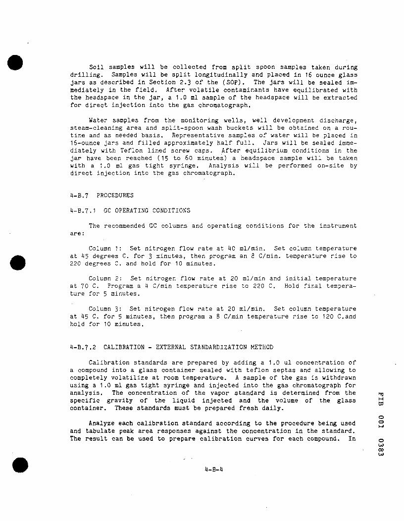
Soil samples will be collected from split spoon samples taken during drilling. Samples will be split longitudinally and placed in 16 ounce glass jars as described in Section 2.3 of the (SOP). The jars will be sealed immediately in the field. After volatile contaminants have equilibrated with the headspace in the jar, a 1.0 ml sample of the headspace will be extracted for direct injection into the gas chromatograph.
Water samples from the monitoring wells, well development discharge, steam-cleaning area and split-spoon wash buckets will be obtained on a routine and as needed basis. Representative samples of water will be placed in l6-ounce jars and filled approximately half full. Jars will be sealed immediately with Teflon lined screw caps. After equilibrium conditions in the jar have been reached (15 to 60 minutes) a headspace sample will be taken with a 1.0 ml gas tight syringe. Analysis will be performed on-site by direct injection into the gas chromatograph.
4-B.7 PROCEDURES
4-B.7.1 GC OPERATING CONDITIONS
The recommended GC columns and operating conditions for the instrument are:
Column 1: Set nitrogen flow rate at 40 ml/min. Set column temperature at 45 degrees C. for 3 minutes, then program an 8 C/min. temperature rise to 220 degrees C. and hold for 10 minutes.
Column 2: Set nitrogen flow rate at 20 ml/min and initial temperature at 70 C. Program a 4 C/min temperature rise to 220 C. Hold final temperature for 5 minutes.
Column 3: Set nitrogen flow rate at 20 ml/min. Set column temperature at 45 C. for 5 minutes, then program a 8 C/min temperature rise to 120 C.and hold for 10 minutes.
4-B.7.2 CALIBRATION - EXTERNAL STANDARDIZATION METHOD
Calibration standards are prepared by adding a 1.0 ul concentration of a compound into a glass container sealed with teflon septas and allowing to completely volatilize at room temperature. A sample of the gas is withdrawn using a 1.0 ml gas tight syringe and injected into the gas chromatograph for analysis. The concentration of the vapor standard is determined from the trj specific gravity of the liquid injected and the volume of the glass container. These standards must be prepared fresh daily. ro
o o Analyze each calibration standard according to the procedure being used
and tabulate peak area responses against the concentration in the standard. The result can be used to prepare calibration curves for each compound. In o
00 00 CO
4-B-4

addition, if the ratio of responses to concentration is constant over the working range, linearity through the origin can be assumed and a calibration factor can be used instead of a calibration curve. The calibration concentration and respective peak areas will then be input into the recorder/data collection system so that subsequent sample concentrations will be calculated automatically.
The working calibration curve or calibration factor must be verified each working day by the measurement of one or more calibration standards.
4-B.7.3 CONCENTRATION CALCULATIONS
Ambient air concentrations will be made automatically in the recorder by comparison of the vapor standards to the peak area response of the injected air samples.
Soil samples are analyzed using the headspace method as described above. The concentration of the volatile components in the vapor space above the soil sample will be measured based on the external vapor standards as described in Section 7.2.
The concentration of a contaminant in a soil sample is the sum of the mass of contaminant in each phase (dissolved and vapor) divided by the mass of the soil sample. The following formulas summarize the calculation:
Cs = mass in (headspace + soil vapor + adsorbed with soil water) mass of soil
Cs = (Vc-Ms/ps)xCh+f(1-ds)xMs/psxCh+fxdsx(Ms/ps)xCh/K Ms
Cs = Chx( Vc-h(Ms/ps)x( fx( 1-dsx( 1-1/H) )-1)) Ms
where: Cs = Concentration is soil sample (mg/kg) Ch = Concentration in headspace vapor (mg/l) Vc = Volume of sample container (1) Ms = Mass of soil sample (kg) ps = Soil density (kg/1) f = Porosity
ds = Degree of Water Saturation H = Henry's Law Constant
The headspace vapor concentration and the weight of soil sample will be ^ measured directly in the field. The volume of the sample container is known and Henry's Law Constants are obtained from published values for each compo- o nent of interest. Soil moisture content, porosity and density are estimated 2 for each soil sample based on previous data or on representative samples taken in the field. o
CO 00
4-B-5
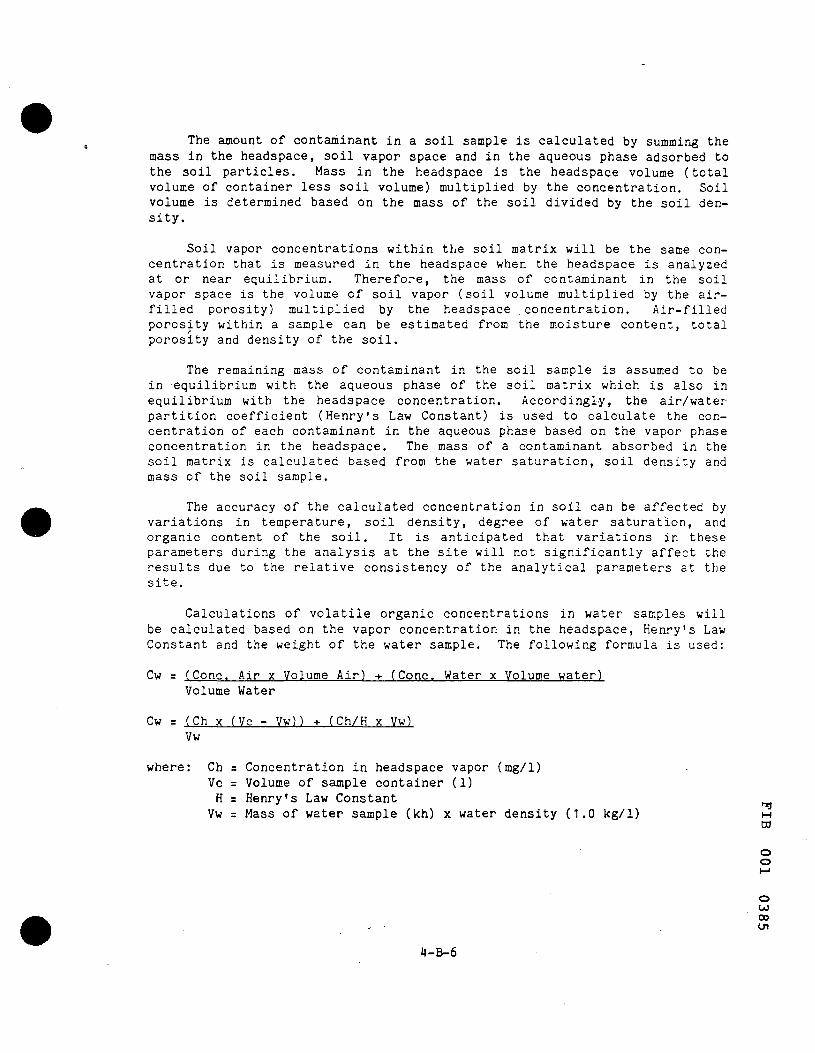
The amount of contaminant in a soil sample is calculated by summing the mass in the headspace, soil vapor space and in the aqueous phase adsorbed to the soil particles. Mass in the headspace is the headspace volume (total volume of container less soil volume) multiplied by the concentration. Soil volume is determined based on the mass of the soil divided by the soil density.
Soil vapor concentrations within the soil matrix will be the same concentration that is measured in the headspace when the headspace is analyzed at or near equilibrium. Therefore, the mass of contaminant in the soil vapor space is the volume of soil vapor (soil volume multiplied by the air-filled porosity) multiplied by the headspace concentration. Air-filled porosity within a sample can be estimated from the moisture content, total porosity and density of the soil.
The remaining mass of contaminant in the soil sample is assumed to be in equilibrium with the aqueous phase of the soil matrix which is also in equilibrium with the headspace concentration. Accordingly, the air/water partition coefficient (Henry's Law Constant) is used to calculate the concentration of each contaminant in the aqueous phase based on the vapor phase concentration in the headspace. The mass of a contaminant absorbed in the soil matrix is calculated based from the water saturation, soil density and mass of the soil sample.
The accuracy of the calculated concentration in soil can be affected by variations in temperature, soil density, degree of water saturation, and organic content of the soil. It is anticipated that variations in these parameters during the analysis at the site will not significantly affect the results due to the relative consistency of the analytical parameters at the site.
Calculations of volatile organic concentrations in water samples will be calculated based on the vapor concentration in the headspace, Henry's Law Constant and the weight of the water sample. The following formula is used:
Cw = (Cone. Air x Volume Air) -f- (Cone. Water x Volume water) Volume Water
Cw = (Ch x (Vc - Vw)) -t- (Ch/H x Vw) Vw
where: Ch = Concentration in headspace vapor (mg/l) Vc = Volume of sample container (1) H = Henry's Law Constant
Vw = Mass of water sample (kh) x water density (1.0 kg/1) M ro
"v
o o
o CO CO Ul
4-B-6

4-B.8 QUALITY CONTROL
Before processing any samples, the analyst will demonstrate through the analysis of a distilled water blank or zero grade air sample that all glassware and reagents are interference-free. Each time a set of samples is extracted or there is a change in reagents, a method blank will be processed as a safeguard against chronic laboratory contamination. Additional field blanks will be drawn every 15 samples. Duplicate samples will be run every 10 samples.
The headspace method of analysis for soil samples is subject to saturation of the vapor space at very high concentrations (typically greater than 5000 ppm). If concentrations in the soil samples are encountered near this level, samples will be preserved for subsequent analysis by an alternative method.
The detection limit of vapor samples by this method is less than 0.5 ug/l. Accordingly, the method detection limit applied to soil samples is less than 1.2 ug/kg for compounds with Henry's Law Constants greater than 0.1 (which includes the standard compounds used here).
ro
o o
o CO 00
4-B-7

FIBERS PUBLIC SUPPLY WELL FIELD REMEDIAL INVESTIGATION/FEASIBILITY STUDY
GUAYAMA, PUERTO RICO
APPENDIX 4-C
QUALITY ASSURANCE/QUALITY CONTROL PROGRAM FOR OTHER ACTIVITIES
M ro
o o
o CO 00 ->1
4-C-1
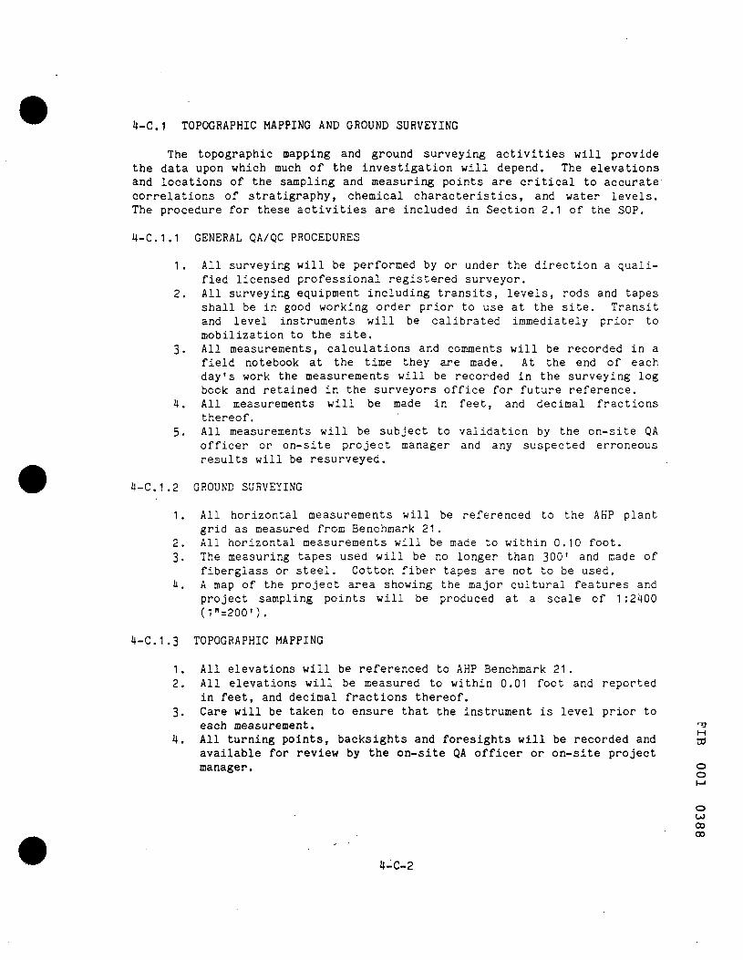
4-C.1 TOPOGRAPHIC MAPPING AND GROUND SURVEYING
The topographic mapping and ground surveying activities will provide the data upon which much of the investigation will depend. The elevations and locations of the sampling and measuring points are critical to accurate correlations of stratigraphy, chemical characteristics, and water levels. The procedure for these activities are included in Section 2.1 of the SOP.
4-C.1.1 GENERAL QA/QC PROCEDURES
1 . All surveying will be performed by or under the direction a qualified licensed professional registered surveyor.
2. All surveying equipment including transits, levels, rods and tapes shall be in good working order prior to use at the site. Transit and level instruments will be calibrated immediately prior to mobilization to the site.
3. All measurements, calculations and comments will be recorded in a field notebook at the time they are made. At the end of each day's work the measurements will be recorded in the surveying log book and retained in the surveyors office for future reference.
4. All measurements will be made in feet, and decimal fractions thereof.
5. All measurements will be subject to validation by the on-site QA officer or on-site project manager and any suspected erroneous results will be resurveyed.
4-C.1.2 GROUND SURVEYING
1 . All horizontal measurements will be referenced to the AKP plant grid as measured from Benchmark 21.
2. All horizontal measurements will be made to within 0.10 foot. 3. The measuring tapes used will be no longer than 300' and isade of
fiberglass or steel. Cotton fiber tapes are not to be used. 4. A map of the project area showing the major cultural features and
project sampling points will be produced at a scale of 1 :2400 (1''=200').
4-C.1.3 TOPOGRAPHIC MAPPING
1 . All elevations will be referenced to AHP Benchmark 21. 2. All elevations will be measured to within 0.01 foot and reported
in feet, and decimal fractions thereof. 3. Care will be taken to ensure that the instrument is level prior to
each measurement. '^ 4. All turning points, backsights and foresights will be recorded and tS
available for review by the on-site QA officer or on-site project manager. o
o M
O CJ CO CO
4-C-2

5. At the end of each day's work, all survey loops will be closed to the day's beginning point of elevation. Any discrepancies in elevations of the beginning point will be reconciled prior to further work.
4-C.2 SURFACE GEOPHYSICAL SURVEYING
The Work Plan for this investigation indicates that surface-geophysical techniques may be utilized as an aid to defining the geology and/or the extent of any contamination at the site. Should this activity be necessary, the following QA/QC procedures will be utilized. The site activities are described in Section 2.2 of the SOP.
4-C.2.1 QA/QC PROCEDURES FOR THE ELECTROMAGNETIC SURVEY
1. Prior to each day's survey, a short traverse will be performed at a location free from cultural interference to assure the instrument's proper operation by determining the repeatability of measurements taken over the same traverse.
2. During the course of each traverse, the results will be examined to identify anomalous readings. In areas where anomalous readings are found, the station spacings will be shortened to either more accurately define the anomaly or determine if it is an erroneous reading.
3. The location of cultural features that may affect the measurement will be recorded during the course of the survey.
4. All data will be plotted on a site plan at the end of each day's work to construct a terrain conductivity contour map. This will aid in identifying erroneous measurements or define anomalous area where more measurements are needed.
5. All results will be compared to soil-sampling data to determine the effectiveness of the EM method.
4-C.2.2 QA/QC PROCEDURES FOR THE VERTICAL ELECTRICAL SOUNDINGS
1. All electrode cables will be checked for integrity of the circuit using a multimeter prior to each day's survey.
2. Multiple readings will be taken at each electrode spacing and averaged to obtain a single value.
3. Data will be plotted on log-log paper at the time they are made to construct a sounding curve of electrode spacing versus apparent resistivity. Any anomalous readings will be measured again to assure an accurate sounding curve.
4. At least seven electrode spacings will be performed per log cycle to aid in data analysis.
5. The data will be reduced and compared to type curves or computer- •"* generated curves to produce the thickness and resistivity of the layers. S
CO
•M H
ro o o
4-C-3

6. All sounding-curve matches will be compared to soil-sampling results to determine effectiveness of the VES method.
4-C.3 HYDROLOGIC TESTING
4-C.3.1 INTRODUCTION
The QA/QC methodologies described below provide a means of obtaining and reporting accurate hydrologic data. These activities require contact with potentially contaminated ground-water. Care must be given to assuring that the proper decontamination procedures are followed between wells.
Documentation of field activities is a significant portion of the site QA/QC and is equally important for these activities. In general, all data sheets will be dated and signed by the person collecting the data. The data sheets will be logged into the field log book for control purposes. Once entered in the log book, the original data sheets will not be carried into the field. Copies, however, will be used in the field for reference. Document-controls specific to each activity are described in the QA/QC methodology for that task.
4-C.3.2 WELL DEVELOPMENT
Each well installed as part of this investigation will be developed as per Chapter 2, Section 2.5.2. The objective of development is to assure good hydraulic connection with the aquifer and to provide water samples as free from turbidity (sediment content) as possible. Both objectives are significant to the proper interpretation of data collected from the wells.
4-C.3.2.1 SUMMARY OF METHOD
The development of the monitoring wells will be accomplished by suction pumping or air-lift pumping, depending on the depth to water below land surface. Air-lift pumping will be the development method. The procedures for well development are described in Section 2.5.2.
4-C.3.2.2 QA/QC PROCEDURES
1. All pumping equipment which will enter the well, such as air hoses and drop pipes, will be steam cleaned prior to installation.
2. All personnel involved in these operations will wear protective -J clothing as prescribed in the health and safety plan (Chapter 5), ro or as modified by the health and safety officer.
3. A record of the amount of water pumped from each well will be o maintained by the task manager and entered into the field log book |_i by the on-site QA officer or on-site manager.
4. Water from the development process will be collected on-site and o not allowed to run overland or to percolate into the soils. o
o
4-C-4

5. Development will be considered complete when the discharge water is clear or when, after 4 hours of development, there has been no decrease in sediment content.
6. The disposal of the development water is discussed in Section 2.5.3. QA/QC procedures for disposal are discussed in 4-C.3.3.
4-C.3.3 DISPOSAL/STORAGE OF WATER
Due to the possibility that the water obtained from wells during the investigation may contain hazardous substances, all water removed from any well must be disposed of properly. These waters will be treated in the AKP wastewater treatment system as described in Section 2.5.3 of the SOP.
4-C.3.3.1 SUMMARY OF METHOD
The transportation of the development water will be by potable tank truck or other suitable container, depending on the volume. Section 2.5.3 of the SOP describes the procedures for this field activity.
4-C.3.3.2 QA/QC PROCEDURES
1 . All personnel involved in this activity will wear protective clothing as prescribed in Chapter 5 of the SOP, or as modified by the health and safety officer.
2. Records of the amount of water transported, the source of the water, and the date and time of transportation will be kept by the task manager or on-site QA officer.
3. The results of the field GC analysis will be approved by AHP personnel prior to discharge.
4. Records of the discharge of these waters into the AHP treatment system (volume, time discharge started, time discharge ended) will be kept by the task manager and a copy provided to AKP personnel.
5. All recorded information regarding transportation, water source, water quantity and quality, and discharge will be maintained by the on-site QA officer.
6. All records will become a permanent record of this investigation, and will be dated and signed.
4-C.3.4 PERMEABILITY TESTING
The movement of ground water in the vicinity of the site depends on the permeability of the sediments comprising the local aquifer. Test borings will be made and monitor wells will be installed and tested to determine the hydrogeologic nature of these sediments.
4-C.3.4.1 SUl«WRY OF METHOD
Testing for permeability will consist of stressing the aquifer by rapidly introducing or removing a solid of a known volume and monitoring the response of the aquifer by measuring the associated water-level changes. i*>
4-C-5
ro
o o
o
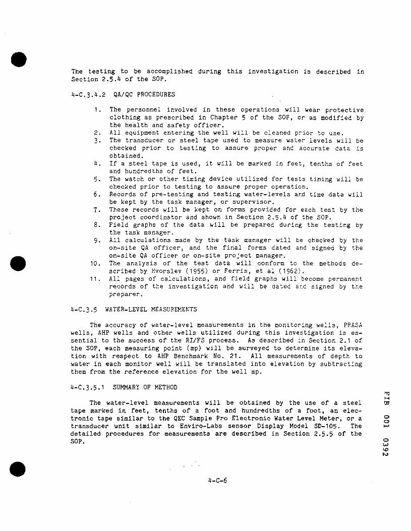
The testing to be accomplished during this investigation is described in Section 2.5.4 of the SOP.
4-C.3.4.2 QA/QC PROCEDURES
1 . The personnel involved in these operations will wear protective clothing as prescribed in Chapter 5 of the SOP, or as modified by the health and safety officer.
2. All equipment entering the well will be cleaned prior to use. 3. The transducer or steel tape used to measure water levels will be
checked prior to testing to assure proper and accurate data is obtained.
4. If a steel tape is used, it will be marked in feet, tenths of feet and hundredths of feet.
5. The watch or other timing device utilized for tests timing will be checked prior to testing to assure proper operation.
6. Records of pre-testing and testing water-levels and time data will be kept by the task manager, or supervisor.
7. These records will be kept on forms provided for each test by the project coordinator and shown in Section 2.5.4 of the SOP.
8. Field graphs of the data will be prepared during the testing by the task manager.
9. All calculations made by the task manager will be checked by the on-site QA officer, and the final forms dated and signed by the on-site QA officer or on-site project manager.
10. The analysis of the test data will conform to the methods described by Hvorslev (1955) or Ferris, et al (1962).
11. All pages of calculations, and field graphs will become permanent records of the investigation and will be dated and signed by the preparer.
4-C.3.5 WATER-LEVEL MEASUREMENTS
The accuracy of water-level measurements in the monitoring wells, PRASA wells, AHP wells and other wells utilized during this investigation is essential to the success of the RI/FS process. As described in Section 2.1 of the SOP, each measuring point (mp) will be surveyed to determine its elevation with respect to AHP Benchmark No. 21 . All measurements of depth to water in each monitor well will be translated into elevation by subtracting them from the reference elevation for the well mp.
4-C.3.5.1 SUMMARY OF METHOD
M The water-level measurements will be obtained by the use of a steel ro
tape marked in feet, tenths of a foot and hundredths of a foot, an electronic tape similar to the QEC Sample Pro Electronic Water Level Meter, or a transducer unit similar to Enviro-Labs sensor Display Model SD-105. The detailed procedures for measurements are described in Section 2.5.5 of the SOP. ."
CO vo ro
4-C-6
o o
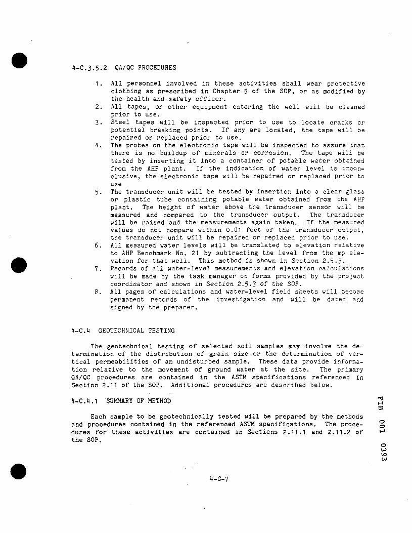
4-C.3.5.2 QA/QC PROCEDURES
1. All personnel involved in these activities shall wear protective clothing as prescribed in Chapter 5 of the SOP, or as modified by the health and safety officer.
2. All tapes, or other equipment entering the well will be cleaned prior to use.
3. Steel tapes will be inspected prior to use to locate cracks or potential breaking points. If any are located, the tape will be repaired or replaced prior to use.
4. The probes on the electronic tape will be inspected to assure that there is no buildup of minerals or corrosion. The tape will be tested by inserting it into a container of potable water obtained from the AHP plant. If the indication of water level is inconclusive, the electronic tape will be repaired or replaced prior to use
5. The transducer unit will be tested by insertion into a clear glass or plastic tube containing potable water obtained from the AHP plant. The height of water above the transducer sensor will be measured and compared to the transducer output. The transducer will be raised and the measurements again taken. If the measured values do not compare within 0.01 feet of the transducer output, the transducer unit will be repaired or replaced prior to use.
6. All measured water levels will be translated to elevation relative to AHP Benchmark No. 21 by subtracting the level from the mp elevation for that well. This method is shown in Section 2.5.3.
7. Records of all water-level measurements and elevation calculations will be made by the task manager on forms provided by the project coordinator and shown in Section 2.5.3 oT the SOP.
8. All pages of calculations and water-level field sheets will become permanent records of the investigation and will be dated and signed by the preparer.
4-C.4 GEOTECHNICAL TESTING
The geotechnical testing of selected soil samples may involve the determination of the distribution of grain size or the determination of vertical permeabilities of an undisturbed sample. These data provide information relative to the movement of ground water at the site. The primary QA/QC procedures are contained in the ASTM specifications referenced in Section 2.11 of the SOP. Additional procedures are described below.
4-C.4.1 SUMMARY OF METHOD ^ W
Each sample to be geotechnically tested will be prepared by the methods and procedures contained in the referenced ASTM specifications. The procedures for these activities are contained in Sections 2.11.1 and 2.11.2 of the SOP.
o o
o CO
vo CO
4-C-7
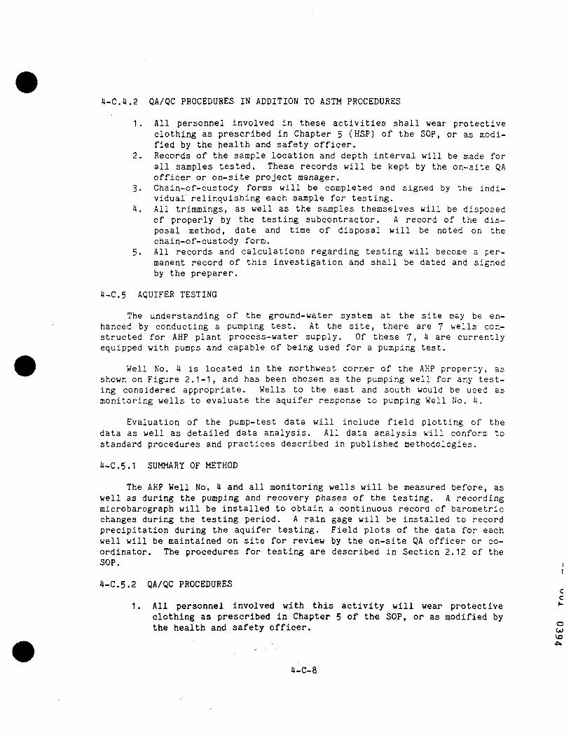
4-C.4.2 QA/QC PROCEDURES IN ADDITION TO ASTM PROCEDURES
1 . All personnel involved in these activities shall wear protective clothing as prescribed in Chapter 5 (HSP) of the SOP, or as modified by the health and safety officer.
2. Records of the sample location and depth interval will be made for all samples tested. These records will be kept by the on-site QA officer or on-site project manager.
3. Chain-of-custody forms will be completed and signed by the individual relinquishing each sample for testing.
4. All trimmings, as well as the samples themselves will be disposed of properly by the testing subcontractor. A record of the disposal method, date and time of disposal will be noted on the chain-of-custody form.
5. All records and calculations regarding testing will become a permanent record of this investigation and shall be dated and signed by the preparer.
4-C.5 AQUIFER TESTING
The understanding of the ground-water system at the site may be enhanced by conducting a pumping test. At the site, there are 7 wells constructed for AHP plant process-water supply. Of these 7, 4 are currently equipped with pumps and capable of being used for a pumping test.
Well No. 4 is located in the northwest corner of the AHP property, as shown on Figure 2.1-1, and has been chosen as the pumping well for any testing considered appropriate. Wells to the east and south would be used as monitoring wells to evaluate the aquifer response to pumping Well No. 4.
Evaluation of the pump-test data will include field plotting of the data as well as detailed data analysis. All data analysis will conform to standard procedures and practices described in published methodologies.
4-C.5.1 SUMMARY OF METHOD
The AHP Well No. 4 and all monitoring wells will be measured before, as well as during the pumping and recovery phases of the testing. A recording microbarograph will be installed to obtain a continuous record of barometric changes during the testing period. A rain gage will be installed to record precipitation during the aquifer testing. Field plots of the data for each well will be maintained on site for review by the on-site QA officer or coordinator. The procedures for testing are described in Section 2.12 of the SOP.
4-C.5.2 QA/QC PROCEDURES
All personnel involved with this activity will wear protective '~ clothing as prescribed in Chapter 5 of the SOP, or as modified by the health and safety officer. c
CO vo
4-C-8

2. The recording microbarograph will be set to the reading obtained from the US Weather Bureau immediately prior to installation on the site.
3. The recording microbarograph will be checked to assure that the clock mechanism and pen are operating properly.
4. All wells measured prior to, during and after the test will have individual pump-test data sheets as shown on Figure 2.12-1.
5. The discharge rate will be measured by the AHP flow recorder currently on the well.
6. All calculations will be checked by the on-site QA officer or the on-site manager. The checked calculation pages will be dated and signed.
7. The analysis of the pumping-test data will conform to standard practices utilized by hydrogeologists. All graphs, data sheets and calculations will be reviewed for accuracy and conformity by the project coordinator.
8. The rain gage will be read, recorded and emptied daily. 9. All calculations, graphs, data sheets and reports generated for
this activity will become a permanent record of this investigation, and will be dated and signed.
4-C.6 COMPUTER MODELING
Computer modeling, if undertaken, will provide a method of simulating past or future ground-water conditions, flow patterns and contaminant plume location. The QA/QC procedures presented in this•section relate to model selection, data preparation, data entry, model calibration and verification, and report generation.
4-C.6.1 SUMMARY OF METHOD
The selection of the model (2.13.3.2) is the most significant element of this QA/QC section. In all cases, the choice of the model relates to the types of data available, the quantity, distribution and accuracy of the data and the modeling needs. The model selection must rely on published as well as project-generated data. The published data include water levels, water quality, regional estimates of hydrologic (aquifer) properties as well as estimates of irrigation and potable water withdrawals. Because of the minimum amount of reliable existing data in the specific area, a detailed ground-water flow model may be inappropriate. The model-selection process will review models to assure that the data needs and data availability are consistent. The procedures for this activity is described in Section 2.13 of the SOP. ni
4-C,6.2 QA/QC PROCEDURES
1. All models reviewed for this activity will be listed by the task o manager and a discussion of their applicability prepared and sub- ""* mitted to the QA officer and project coordinator for review.
CO
vo
4-C-9
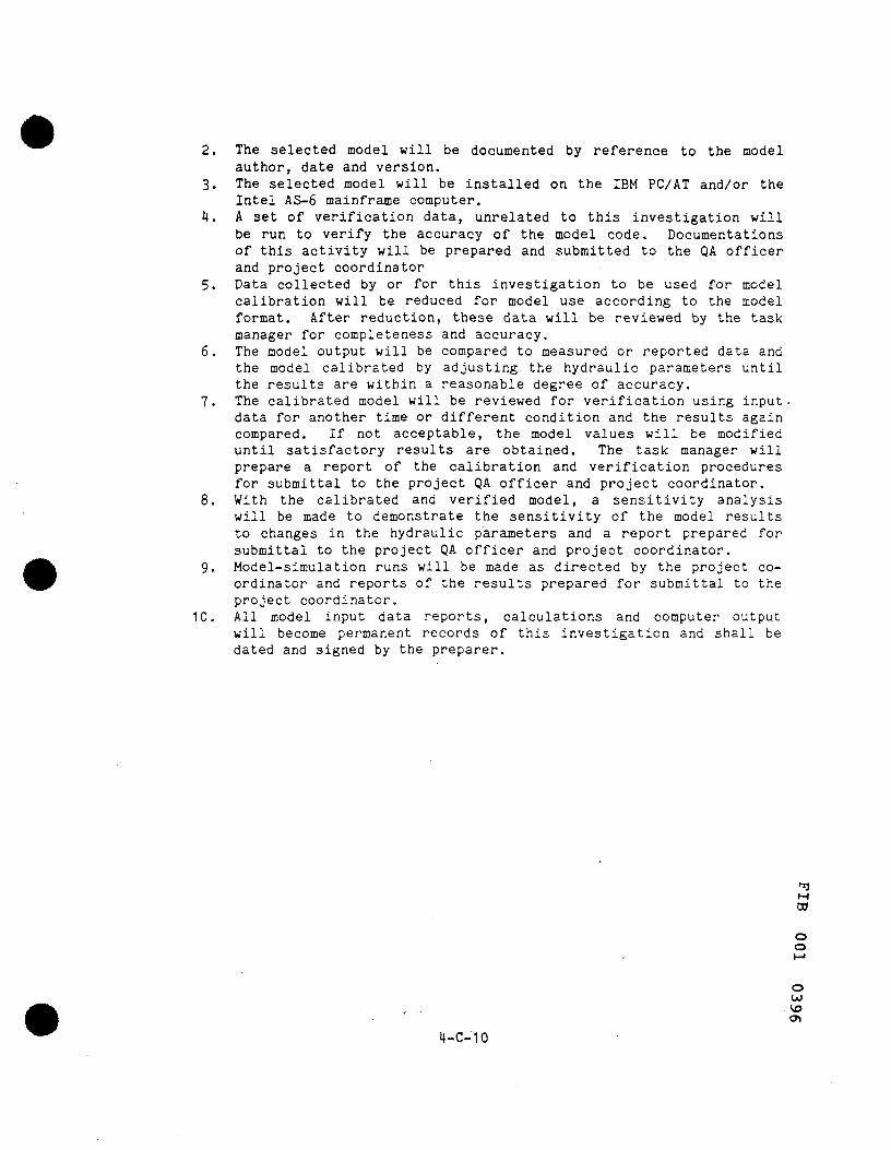
2. The selected model will be documented by reference to the model author, date and version.
3. The selected model will be installed on the IBM PC/AT and/or the Intel AS-6 mainframe computer.
4. A set of verification data, unrelated to this investigation will be run to verify the accuracy of the model code. Documentations of this activity will be prepared and submitted to the QA officer and project coordinator
5. Data collected by or for this investigation to be used for model calibration will be reduced for model use according to the model format. After reduction, these data will be reviewed by the task manager for completeness and accuracy.
6. The model output will be compared to measured or reported data and the model calibrated by adjusting the hydraulic parameters until the results are within a reasonable degree of accuracy.
7. The calibrated model will be reviewed for verification using input-data for another time or different condition and the results again compared. If not acceptable, the model values will be modified until satisfactory results are obtained. The task manager will prepare a report of the calibration and verification procedures for submittal to the project QA officer and project coordinator.
8. With the calibrated and verified model, a sensitivity analysis will be made to demonstrate the sensitivity of the model results to changes in the hydraulic parameters and a report prepared for submittal to the project QA officer and project coordinator.
9. Model-simulation runs will be made as directed by the project coordinator and reports of the results prepared for submittal to the project coordinator.
10. All model input data reports, calculations and computer output will become permanent records of this investigation and shall be dated and signed by the preparer.
M ro
o o
o CO
vo 4-C-10

HEALTH AND SAFETY PLAN
REMEDIAL INVESTIGATION/FEASIBILITY STUDY
Fibers Public Supply Weil Field
Guayama. Puerto Rico
Prepared by
LEGGETTE, BRASHEARS & GRAHAM, INC.
1211 North Westshore Boulevard
Tampa, Florida 33607
APRIL. 1986
a
o o
o CO vo

5.0 HEALTH AND SAFETY PLAN
5.1 PROJECT DESCRIPTION
The Fibers Public Supply Well is located on the south side of Route 3 in Guayama, Puerto Rico. Figure 5.1-1 is a general index map of Puerto Rico showing the approximate location of the well field. Four of the five supply wells have been shut-down by the operator, the Puerto Rico Aqueducts and Sewer Authority (PRASA), as a result of reported contamination. Water samples collected from the wells in 1983 by the United States Environmental Protection Agency (USEPA) showed elevated levels of volatile organic compounds in the four wells that were shut-down. The wells have been included on the National Priorities List (NPL) of known and threatened releases of hazardous substances.
Studies performed by the United States Geological Survey (USGS) indicate that the Fibers Public Supply Wells are located downgradient of an industrial facility that was operated by Ayerst-Wyeth Pharmaceuticals, Inc., a subsidiary of American Home Products (AHP). This facility had been operated from 1966 to 1980 by subsidiaries of Phillips Petroleum Company and Chevron Chemical Company. During this period of time, wastewater from the facility was stored in two lagoons located on the north side of Route 3. A third adjacent lagoon to the west was utilized for storm water management. The USEPA believes the two wastewater lagoons are the source of the contamination at the PRASA wells. In I985, the three lagoons were modified by AKP to provide a single storm water management facility.
Phillips and Chevron have voluntarily entered into an agreement with the USEPA to conduct a Remedial Investigation and Feasibility Study (RI/FS) at the site. The general purposes of this RI/FS are: to confirm the presence, nature and extent of contamination; to identify the sources of contamination, to evaluate alternative and recommend a cost-effective remediation plan that will provide protection of the public health and welfare, and the environment.
Additional information pertaining to the requirements for conducting the RI/FS at the site is included in the USEPA Administrative Order, Index No. II - CERCLA 50301, and in a document entitled "Work Plan, Remedial Investigation/Feasibility Study, Fibers Public Supply Well Field, Guayama, Puerto Rico," dated October 1985.
This Health and Safety Plan (HSP) is intended to provide a basic frame- ^ work for the safe conduct of the investigations at the Fibers Public Supply ^ Well Field, Guayama, Puerto Rico. The procedures contained in the HSP are based upon information presented in the above-referenced work plan and an o evaluation of site conditions by health and safety (H/S) personnel of both ^ Phillips and Chevron. These procedures provide a guide for all contractor and subcontractor employees who will be involved in the performance of the cP
vo CO
5-1

FIBERS PUBLIC SUPPLY WELL FIELD
RI/FS
GUAYAMA, PUERTO RICO
FIGURE 5.1-1 GENERALIZED SITE LOCATION MAP
ATLANTIC OCEAN
VJl
ro
WAYAGUEZ
SAN JUAN
POf^Ct GUAYAMA
OBOS ^ " 3 ^ * /
PROJECT SITE
CARIBBEAN SEA i^ SCALE
0 6 MILES
66£0 TOO a i d
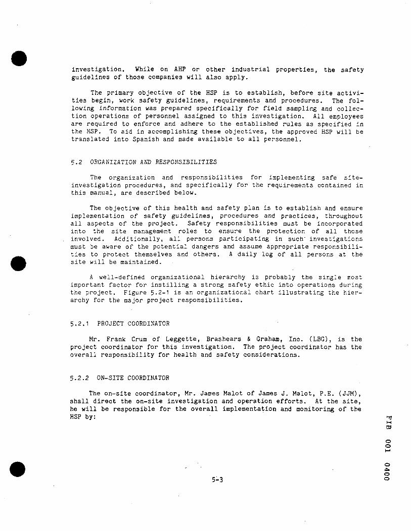
investigation. While on AHP or other industrial properties, the safety guidelines of those companies will also apply.
The primary objective of the HSP is to establish, before site activities begin, work safety guidelines, requirements and procedures. The following information was prepared specifically for field sampling and collection operations of personnel assigned to this investigation. All employees are required to enforce and adhere to the established rules as specified in the HSP. To aid in accomplishing these objectives, the approved HSP will be translated into Spanish and made available to all personnel.
5.2 ORGANIZATION AND RESPONSIBILITIES
The organization and responsibilities for implementing safe site-investigation procedures, and specifically for the requirements contained in this manual, are described below.
The objective of this health and safety plan is to establish and ensure implementation of safety guidelines, procedures and practices, throughout all aspects of the project. Safety responsibilities must be incorporated into the site management roles to ensure the protection of all those involved. Additionally, all persons participating in such' investigations must be aware of the potential dangers and assume appropriate responsibilities to protect themselves and others. A daily log of all persons at the site will be maintained.
A well-defined organizational hierarchy is probably the single most important factor for instilling a strong safety ethic into operations during the project. Figure 5.2-1 is an organizational chart illustrating the hierarchy for the major project responsibilities.
5.2.1 PROJECT COORDINATOR
Mr. Frank Crum of Leggette, Brashears & Graham, Inc. (LBG), is the project coordinator for this investigation. The project coordinator has the overall responsibility for health and safety considerations.
5.2.2 ON-SITE COORDINATOR
The on-site coordinator, Mr. James Malot of James J. Malot, P.E. (JJM), shall direct the on-site investigation and operation efforts. At the site, he will be responsible for the overall implementation and monitoring of the HSP by: ^
M
ro o o
M
O
o 5-3 o
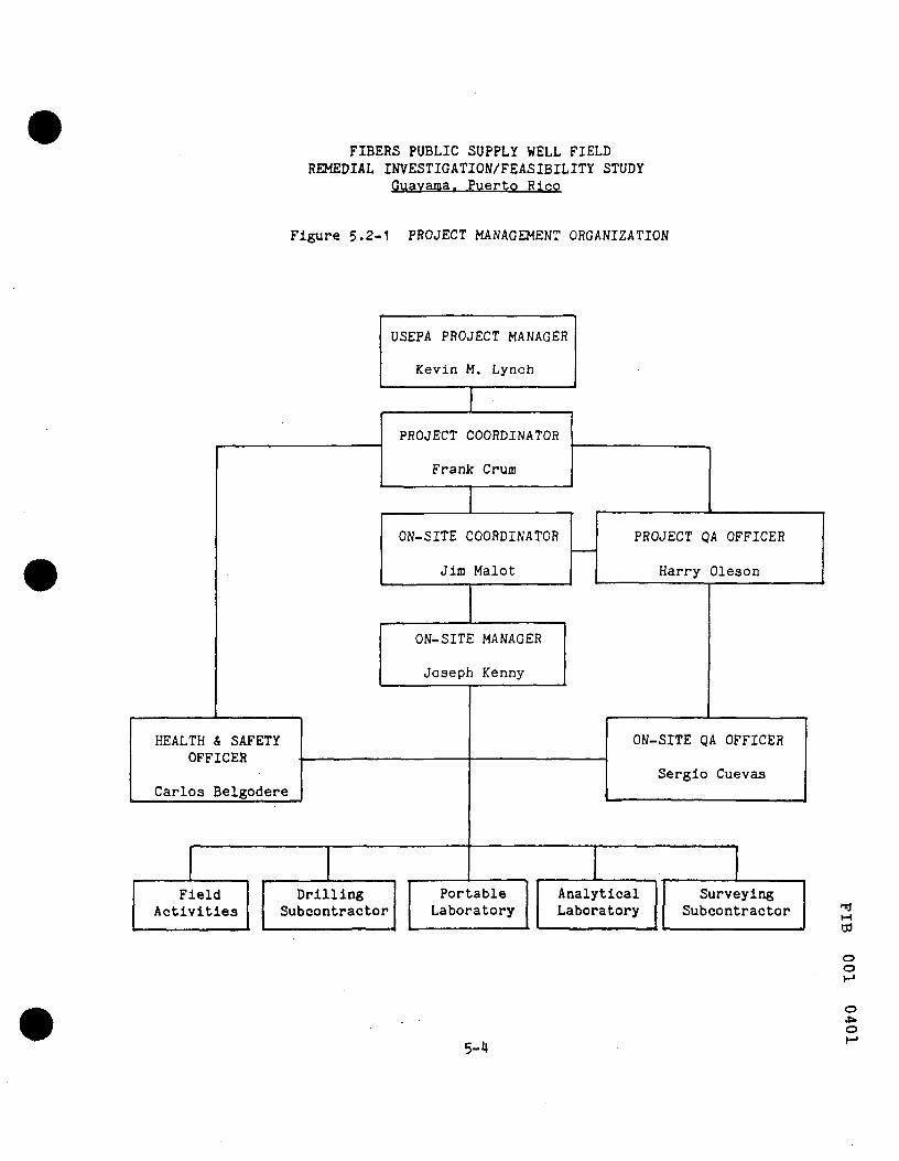
FIBERS PUBLIC SUPPLY WELL FIELD REMEDIAL INVESTIGATION/FEASIBILITY STUDY
Guavama. Puerto Rico
Figure 5.2-1 PROJECT MANAGEMENT ORGANIZATION
HEALTH & SAFETY OFFICER
Carlos Belgodere
Field Activities
USEPA PROJECT MANAGER
Kevin M. Lynch
PROJECT COORDINATOR
Frank Crum
ON-SITE COORDINATOR
Jim Malot
ON-SITE MANAGER
Joseph Kenny
Drilling Subcontractor
Portable Laboratory
PROJECT QA OFFICER
Harry Oleson
ON-SITE QA OFFICER
Sergio Cuevas
Analytical Laboratory
Surveying Subcontractor M
W
o o
5-4
o O

1. Assuring that personnel are aware of the provisions of the HSP. 2. Assuring that appropriate, personal-protective equipment is avail
able and properly used by all on-site personnel. 3. Assuring that personnel are aware of potential hazards associated
with site operations. 4. Supervising and monitoring the safety performance of all personnel
to ensure that the required work practices are employed. 5. Correcting any work practices or conditions that may result in
injury or exposure to hazardous substances. 6. Preparing accident/incident reports.
5.2.3 HEALTH AND SAFETY OFFICER
The health and safety officer, Mr. Carlos Belgodere (JJM), will coordinate the health and safety program and will be responsible for the following:
1. Advising the on-site coordinator and task managers on health and safety policy issues.
2. Providing advice to the work teams on operational and logistical options.
3. Conducting, or requesting to be conducted, site monitoring of personal hazards to determine the degree of hazard present.
4. Recommending proper and necessary clothing and equipment to ensure the safety of operating personnel.
5. Verifying that all protective equipment is in proper working order.
6. Evaluating chemical hazard information and recommending necessary modification to work and safety plans.
7. Ensuring that health and safety training programs are available and that all site personnel have received this training.
8. Monitoring the effectiveness of the health and safety plan as it is conducted in the field by performing field operation audits.
9. Following up on any necessary corrective actions. 10. Interacting with the USEPA field representative regarding modi
fications of health and safety actions.
5.2.4 TASK MANAGERS
The task managers are the field-supervisory personnel such as the field geologist and field analyst. This also includes supervisory personnel of subcontractors. They will be accountable for direct supervision of their assigned personnel with regard to:
" 1. Health and safety program compliance. ^ 2. Maintaining a high level of health and safety consciousness among
employees on site. o 3. Reporting accidents within their jurisdiction and undertaking cor
rective action.
o
o o NO
5-5

4. Ensuring sufficient protective equipment is provided and used. 5. Promptly initiating emergency alerts.
For this investigation, a task manager will be designated by the sub-contractor(s) to assure adequate implementation of these guidelines and procedures.
5.2.5 FIELD PERSONNEL
All field personnel will report directly to their respective task managers and will be required to:
1. Receive task-specific health and safety training for their assigned site activities.
2. Be familiar with, and conform to, provisions of the HSP. 3. Ensure they are well informed of potential hazards on site and
exercise informed consent in working on site. 4. Report any accidents or hazardous conditions. 5. Have complete familiarity with their job requirements and the
health and safety procedures involved.
5.3 RISK ASSESSMENT AND PERSONAL PROTECTION
The presence of chloroethylene compounds (tetrachoroethylene and trichioroethylene) reported to be in and around the proposed sampling locations comprise the major concern for personal health. The low levels detected during water-quality sampling by the USEPA in 1983 were not of concern on a limited exposure basis. Nevertheless, the protection of personal exposure to these substances by inhalation, oral injection or dermal absorption is included in this plan. The health and safety officer is responsible for determining the level of personal-protection equipment required. When site conditions warrant, the health and safety officer will modify the level of protection to be utilized in the field.
An organic vapor analyzer (OVA) will be used to monitor ambient air quality at the site. During drilling operations, air quality will be monitored at each drilling location. Work operations which involve handling of potentially hazardous substances will include continuous contaminant monitoring using a direct-reading field OVA.
When deemed necessary or desirable by the health and safety officer, ^ area monitoring will be used in high hazard operations and in hazardous W zones on site. Area monitoring will be performed as plans and conditions dictate, and in accordance with the HSP and with the goal of accident and hazardous condition prevention in mind.
o o
o
o CO
5-6
5.3.1 PERSONAL PROTECTIVE EQUIPMENT
At a minimum, protective headgear, eyewear and footwear will be worn at all times by personnel working around the drilling equipment. Should site conditions dictate, protective gloves and rubber boots may be required for those personnel handling contaminated soils or water at the site. Respirators for all personnel at the site will be available with both particulate and organic vapor protection cartridges. The health and safety officer will direct when the protective clothing and respirators will be utilized based on the conditions encountered at the site.
Only protective equipment deemed suitable by the health and safety officer for use on site will be worn. Any changes in protection levels shall be documented by the health and safety officer. Respirators will be cleaned dally and cartridges changed at least once per each eight hours of use. On~site field personnel should exercise informed judgment on protective gear requirements at active sites or at sites that have been repeatedly entered or occupied without apparent harm. In any case where doubt exists, the safe course of action must be taken.
5.3.2 SAFE WORK PRACTICES
In addition to the use of protective equipment, other procedures will be followed to miminize risk.
1. All consumptive activities including eating, drinking or smoking are prohibited during drilling, sampling and decontamination activities.
2. Portable emergency eye washes will be located on site during drilling, sampling and decontamination activities.
3. An adequate source of potable water to allow for emergency use will be available at the drilling sites.
4. Fire extinguishers will be on-site for use on equipment or small fires.
5. An adequately stocked first-aid kit will be on-site at all times during operational hours.
5.4 EMERGENCY CONTACTS
In the event of a safety or health emergency, appropriate corrective measures must immediately be taken to assist those who have been injured or exposed and to protect others from hazard. The on-site safety officer will be notified of the incident immediately. If necessary, first aid will be ^ rendered.
o
o
'q
5-7
1. Fire 864-2330 2. Police 864-2020 3. Hospital 864-4300 4. AHP Doctor (office) 864-0101
AHP Doctor (home) 864-4984 AHP Ambulance 864-0101
5.5 TRAINING
Training will consist of hazard-awareness training, use of protective clothing and equipment, and respirator use. Training will take place prior to commencement of work at the site. A log of personnel completing the training will be maintained and training certificates will be given to each individual completing the training. The certificate must be carried at all times during work activities on this project.
Hazard-awareness training will include a review of the suspected hazardous substances on-site, their physical and chemical properties, toxicity, health effects and symptoms of exposure. Emphasis will be placed on the practical reasons for and means of avoiding exposure to hazardous materials and other hazards.
Proper use of protective clothing and equipment will be demonstrated. Personnel involved in work on-site will be prepared to use air purifying respirators. Before being allowed to use a respirator, personnel will receive training in the use of respirators which will include:
1. Purpose of wearing respirators 2. How the respirator works 3. Limitations 4. Fit testing 5. Maintenance 6. Conditions of use
o
o O Ul
5-8
6.0 CONTINGENCY PLAN
A contingency plan has been developed to address the possibility of fire or serious accident during the outlined field activities. During all field activities an adequately stocked first-aid kit and fire extinguishers, for use on equipment or small fires, will be on-site at all times during operational hours. Emergency contacts will be posted at the site and are included in the Health and Safety Plan.
Hazards from fire could be localized as in equipment fires or relatively large as in a cane-field fire. In either case, the primary goal is personal safety. If judgment indicates the possibility of extinguishing the fire or removal of equipment, extreme care should be taken. The appropriate agencies should be notified and field personnel should move to a place of safety.
Basic emergency first-aid procedures should be followed in the case of serious injuries caused by accidents. If needed, the injured party should be moved to a place of safety. Help should be called immediately if this can be accomplished without leaving the victim alone. An attempt should be made to stop or restrict any serious bleeding. The victim should be treated for the possibility of shock and should remain quiet (still).
6-1
M
ro
o o
o o
7.0 PROJECT PROFESSIONAL PERSONNEL
Chapter 1 of the SOP contains the major project organization and the supervisory responsibilities for the site activities. Table 7-1 displays the names of the project personnel and the site activities to which each is assigned. The curriculum vitae of the project personnel are included in Appendix 7-A.
H ro o o
o o -J
7-1

FIBERS PUBLIC SUPPLY WELL FIELD REMEDIAL INVESTI GAT IQN/FEASIBILI TV STUDY
Guayamd, Puerto Rico
Table 7-1 PROJECT PROFESSIONAL INVOLVEMENT
I
SECTION NUMBER
SECTION TITLE
LEGGETTE, BRASHEARS '/ GRAHAM, INC. FHC HFQ 5SF FL -AiB JM DS JK8 HBB
JAMES J. MALOT, P.E. JJM Ji; SC CB AC MOM
2 . 1 ; n F Q , - : A F P I N 6 , GftG'JMD S'Jfi'.'E V ;'.'G 2 . 2 : SURFACE GECFHrSiCE 2 . 3 : S a i L - B O R H i G A C T I V I TIES 2.4 ; MQNi T O R : N G - W E L L INSTALLA;:C;'I
2.5 I HYDROLOGIC TESTING 2.i : GROUND-WATER SAMPLING 2.7 : SURFACE-WATER SAMPLING 2.8 1 SEDIMENT SAMPLING 2 . 1 ; WATER-QUALITY ANALYSIS
2. 10 : SOIL-QUALITY ANALYSIS 2.11 : GEOIECHINICAL TESTING 2.12 I AQUIFER TESTING 2.13 i COMPUTER MODELING 2.14 I DATA VALIDATION, EVALUATION
; AND Rl REPORT PREPARATION
80^0 TOO a i d
FIBERS PUBLIC SUPPLY WELL FIELD REMEDIAL INVESTIGATION/FEASIBILITY STUDY
GUAYAMA, PUERTO RICO
APPENDIX 7-A
CURRICULUM VITAE OF PROJECT PROFESSIONALS
ro
O o
o o vo
7-A-1

G. SIDNEY FOX (GSF)
EDUCATION: Bachelor of Science in Engineering (Geological Engineering), 1950, from Princeton University. Graduate work at Stanford University, 1950
REGISTRATION:
Delaware;
Certified as Professional Geologist by the American Institute of Professional Geologists;
Registered Geologist in the states of California and
Certified Professional Geologist in the State of Indiana
TECHNICAL American Institute of Professional Geologists (Vice SOCIETIES: President, Northeast Section, 1974. Member, Executive
Committee,1973); American Geophysical Union; American Institute of Mining, Metallurgical and Petroleum Engineers (Chairman, Hydrology Unit Committee, 1972);
American Water Resources Association; Association of Engineering Geologists (Chairman, New York-Philadelphia Section, 1982-84)
SUMMARY OF PROFESSIONAL EXPERIENCE:
I95I-I955: Ground-Water Engineer with the Ground-lvater Branch of the U. S. Geological Survey in New Jersey
1955: Engineer with the American V/ater V/'orks Service Com.pany
1955-1966: Ground-Water Geologist with the firm of Leggette, Brashears & Graham
1967-1976: Partner In the firm of Leggette, Brashears & Graham
1976-1984: Vice President and Director of Leggette, Brashears & Graham, Inc.
1984 to date: Executive Vice President and Director of Leggette, Brashears & Graham, Inc.
Experience includes areal hydrogeologic reconnaissance studies in Pennsylvania, New Jersey and Turkey; investigations for public water supplies in Pennsylvania, New Jersey, New York, Massachusetts, Ohio, Illinois, South Carolina, Florida and the Caribbean region; investigations for industrial water supplies in Pennsylvania, New Jersey, Virginia, Florida, Missouri, Wyoming and Turkey; investigations of ground-water pollution in Pennsylvania, New Jersey, New York, Delaware, Texas and Utah; investigations for dewatering in New York and Minnesota; presentation of expert testimony
M W
o o
o
7-A-2

in legal proceedings in Jew Jersey, Pennsylvania and New York; design and supervision of exploratory drilling and pumping tests, for the evaluation of ground-water supply potentials; design ' and supervision of test drilling, monitor well installation, ground-water sampling and remedial measures for ground-water pollution problems.
ro
o o
O
7-A-3

FRANK H. CRUM (FHC)
EDUCATION: Bachelor of Science in Geology, 1959, from Union College, Schenectady, New York
REGISTRATION: Certified as Professional Geologist by the American Institute of Professional Geologists;
Registered Geologist in the states of Georgia and Indiana; Certified as Professional Hydrogeologist by the American Institute of Hydrology
TECHNICAL American Institute of Professional Geologists; SOCIETIES: American Institute of Hydrology;
American Water Resources Association; American Water Works Association (Member, Water Resources
/ Committee, Florida Section, 1975-1981); Association of Ground Water Scientists and Engineers
(National Water Well Association); Florida Water Well Association; Florida Pollution Control Association, Inc. (Member, Water Resources Committee)
Geological Society of America;
SUMMARY OF PROFESSIONAL EXPERIENCE:
1959-1969: Ground-Water Geologist with the firm of Leggette, Brashears & Graham
1969-1974: Senior Hydrogeologist with the firm of Leggette, Brashears & Graham
1975-1976: Partner in the firm of Leggette, Brashears & Graham
1976-1984: Vice President and Director of Leggette, Brashears & Graham, Inc.
1984 to date: Senior Vice President and Director of Leggette, Brashears 4 Grahamj Inc.
Experience includes extensive involvement in hydrogeological studies in the Coastal Plain aquifers on the Atlantic and Gulf coasts; geologic reconnaissance studies; design and supervision of exploratory drilling; planning and execution of pumping tests to determine aquifer yield, water quality, aquifer limits, well spacing, contamination sources and salt-water encroachment potential; evaluation of regional impacts of ground-water withdrawals; design of ground-water supplies for industrial plant sites; investigation of deep-well disposal feasibility; areal ground-water inventories and reports; environmental impact statements pertaining to ground-water usage; evaluation
Tl M ro
o o
o
to
7-A-4

of mine dewatering systems; studies of ground-water contamination potential and compliance to RCRA; permitting of ground-water withdrawals; direction and administration of projects; presentation of expert testimony in administrative and legal proceedings. Experience in 18 states includes major field investigations in Florida, Alabama, North Carolina, Texas, Virginia, Maryland, New Jersey, New York and in Australia.
i-i
ro
o o
o
CO
7-A-5
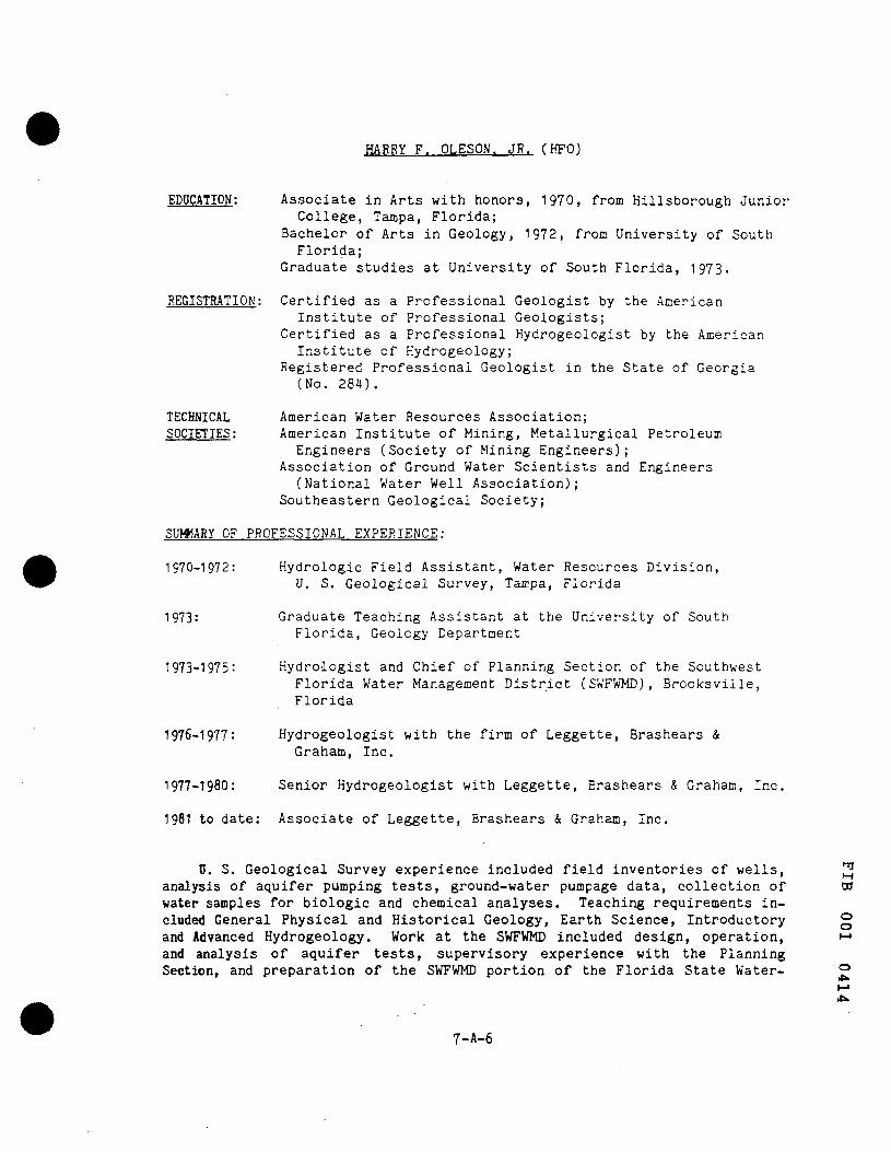
HARRY F. OLESON. JR. (HFO)
EDUCATION: Associate in Arts with honors, 1970, from Hillsborough Junior College, Tampa, Florida;
Bachelor of Arts in Geology, 1972, from University of South Florida;
Graduate studies at University of South Florida, 1973.
REGISTRATION: Certified as a Professional Geologist by the American Institute of Professional Geologists;
Certified as a Professional Hydrogeologist by the American Institute of Kydrogeology;
Registered Professional Geologist in the State of Georgia (No. 284).
TECHNICAL American Water Resources Association; SOCIETIES: American Institute of Mining, Metallurgical Petroleum
Engineers (Society of Mining Engineers); Association of Ground Water Scientists and Engineers
(National Water Well Association); Southeastern Geological Society;
SUW1ARY OF PROFESSIONAL EXPERIENCE
1970-1972: Hydrologic Field Assistant, Water Resources Division, U. S. Geological Survey, Tampa, Florida
1973: Graduate Teaching Assistant at the University of South Florida, Geology Department
1973-1975: Hydrologist and Chief of Planning Section of the Southwest Florida Water Management District (SWFWMD), Brooksville, Florida
1976-1977: Hydrogeologist with the firm of Leggette, Brashears & Graham, Inc.
1977-I98O: Senior Hydrogeologist with Leggette, Brashears & Graham, Ine,
1981 to date: Associate of Leggette, Brashears & Graham, Inc.
0. S. Geological Survey experience included field inventories of wells, analysis of aquifer pumping tests, ground-water pumpage data, collection of water samples for biologic and chemical analyses. Teaching requirements included General Physical and Historical Geology, Earth Science, Introductory and Advanced Kydrogeology. Work at the SWFWMD included design, operation, and analysis of aquifer tests, supervisory experience with the Planning Section, and preparation of the SWFWMD portion of the Florida State Water-
Ti M ro
o o
o
7-A-6
Use Plan. Consulting experience includes planning and conducting aquifer tests and well-field development for large municipal supplies, investigation of the feasibility of deep-well disposal and studies of contamination problems. Experience with digital-computer models includes the design and calibration of models to predict both individual well and regional effects of large scale municipal withdrawals in the United States and abroad, the design of a model to predict the effectiveness and optimization of depres-surizing for mining purposes, and the design and preparation of numerous general and site-specific minicomputer programs for water-resource purposes. Contamination-related experience includes the design and supervision of contamination-assessment studies, permit-application submittals and compliance reporting, and the design of recovery ^nd abatement programs. Field studies have been done in Alabama, Florida, North Carolina, Ohio and Virginia.
o CJ
o
(J I
7-A-7
ROBERT LAMONICA (RL)
EDUCATION: Bachelor of Arts in Geology, 1974, from the State University of New York College at Cortland, New York
REGISTRATION: Certified as Professional Geologist by the American Institute of Professional Geologists;
Certified as Professional Geologist in Virginia
TECHNICAL American Institute of Professional Geologists (Member, SOCIETIES: Executive Committee, Northeast Section, 1979-1982);
Association of Ground Water Scientists and Engineers (National Water Well Association);
Geological Society of America;
SUMMARY OF PROFESSIONAL EXPERIENCE:
1974: (Summer) Hydrologic Field Assistant, Cortland County Planning
Board, and Housing and Urban Development Agency
1976-1979: Hydrogeologist with Leggette, Brashears & Graham, Inc.
1980-1981; Senior Hydrogeologist with Leggette, Brashears & Grahar., Inc.
1982 to date: Associate of Leggette, Brashears & Graham, Inc.
Field experience includes supervision of test drilling, geophysical logging, pumping-test supervision and analysis, monitoring of water levels and data correlation for water-supply investigations, and regional groundwater availability studies. Extensive experience with municipal and industrial pollution evaluation and monitoring. Coordination of project management and regulatory agency participation and review. Field investigations in New York, Pennsylvania, Connecticut, New Jersey, West Virginia, Virginia, South Carolina, Oklahoma and Rhode Island.
Ground-water contamination investigations include wood treatment chemicals, pesticides, herbicides, petroleum products, fertilizer, solvents, plastics, metals, mixed industrial wastes and municipal landfill leachate.
M
ro o o
7-A-8
o
<Tl

WILLIAM K. BECKMAN (WKB)
EDUCATION:
REGISTRATION:
Bachelor of Science in Civil and Environmental Engineering, 1976, from University of Rhode Island
Master of Science in Civil and Environmental Engineeririg, 1978, from the University of Rhode Island
Registered Professional Engineer in the States of Connecticut and Minnesota
TECHNICAL Associate Member, American Society of Civil Engineers; SOCIETIES: Association of Ground Water Scientists and Engineers
(National Water Well Association)
SUMMARY OF PROFESSIONAL EXPERIENCE:
1976-1978: Research Assistant, Civil Engineering Department, University of Rhode Island
1978-1980:
1981-1984:
1985 to date:
Hydrologist with Leggette, Brashears & Graham, Inc.
Senior Hydrologist with Leggette, Brashears & Graham, Inc.
Associate with Leggette, Brashears & Graham, Inc.
Present duties lie primarily in project management and supervision of computer applications. Recent experience includes management of remedial investigations at three Superfund sites, development of monitoring program for a major east coast refinery, and utilization of 2-D solute transport and 3-D ground-water flow models in hydrogeologic evaluations. Also, numerous environmental assessments, including expert testimony, regarding impacts on the hydrogeology.
Previous experience includes development, construction and analysis of electrical-analog and digital computer models for ground-water flow and contaminant transport; collection of earth resistivity, seismic and gravity survey data; supervision of well drilling, well development, aquifer testing and analysis of data; geological and geophysical logging; investigation of well loss, water supply, water budget and water-quality (including hazardous waste and hydrocarbons) problems. Office investigation of projects in North Carolina, West Virginia, Saudia Arabia and Suriname; field experience in Connecticut, Kentucky, Massachusetts, Minnesota, New Hampshire, New York, New Jersey and Pennsylvania.
Tl H ro
o o
o
7-A-9
JOHN NASO. JR. (JN)
EDUCATION; Bachelor of Arts in Geology, 1972, from Lehman College/C.U.N.Y.
Master of Science in Geology, 1975, from the University of Massachusetts at Amherst
Enrichment studies in Biology from Cornell University, 1976
REGISTRATION: Certified as Professional Geologist by the American Institute of Professional Geologists;
Certified Professional Geologist in the States of Indiana and Virginia
TECHNICAL American Institute of Professional Geologists (Member); SOCIETIES; Association of Engineering Geologists
(Vice Chairman, New York-Philadelphia Section, 1984-1986); Association of Ground Water Scientists and Engineers
(National Water Well Association)
SUMMARY OF PROFESSIONAL EXPERIENCE:
1979-1972: Laboratory Assistant, Lehman College, work in Paleontology
1972-1973:
1973-1974:
1974-1975:
1975-1977:
1978-1981:
1982 to date:
Consultant to Northeast Utilities Co., Hartford, Connecticut for special project entitled, "Geologic Survey to Identify and Rank Prospective Areas for the Excavation of Underground Caverns for the Storage of Compressed Air and/or Water in New England"
Teaching Associate, University of Massachusetts at Amherst Physical and Historical Geology
Research Assistant, University of Massachusetts
Teacher in Earth and Physical Science
Hydrogeologist with Leggette, Brashears & Graham, Inc.
Senior Hydrogeologist with Leggette, Brashears & Graham, Inc.
Experience includes design and supervision of exploratory drilling in overburden materials and bedrock; planning and executing pumping test for determining aquifer yield, water quality, aquifer limits; evaluation of regional effects of large ground-water withdrawals; geophysical logging; well design; monitoring of water levels; data input for ground-water computer modeling. Ground-water pollution experience includes supervision of exploratory drilling and monitor-well installation and water-quality sampling. Field work conducted in new York, New Jersey, Pennsylvania, Indiana, Connecticut, Virginia, Massachusetts, Rhode Island and New Hampshire.
M ro
o o
o
7-A-10 CO

JOE K. BUERHOP (JKB)
EDUCATION:
TECHNICAL SOCIETIES:
Bachelor of Arts Degree in Geology, I98O, from the University of South Florida. Additional courses in Hydrology and Geophysics.
Association of Ground Water Scientists and Engineers (National Water Well Association)
SUMMARY OF PROFESSIONAL EXPERIENCE:
1981 to date: Hydrogeologist with Leggette, Brashears & Graham, Inc.
Field experience includes supervision of drilling, development and testing of public and industrial supply wells, planning and executing pumping tests for determining well yield, water-quality characteristics, aquifer hydraulic properties, and well interference calculations, monitoring of ground-water impacts from major governmental well fields; design of well construction details, preparation of drilling specifications; evaluation of ground-water conditions in the vicinity of industrial operations; supervision of drilling and installation of chemical and hydrocarbon contamination recovery wells; implementation of monitoring programs major field investigation of RCRA Superfund site including installation of monitor and recovery wells; preparation of annual status reports. Experience with digital-computer models to predict both local and regional effects of ground-water withdrawals. Field work conducted in Florida, North Carolina, South Carolina, Minnesota and New Hampshire.
Tl M ro
o o
7-A-11
o
vo
HENRY B. BARKER (HBB)
EDUCATION: Bachelor of Science in Geology, 1980, from West Georgia College, Carrollton, Georgia
Completing Masters of Science degree in Geology, University of South Florida
TECHNICAL Geological Society of America SOCIETIES: Southeastern Geological Society
Association of Ground Water Scientists and Engineers (National Water Well Association)
SUMMARY OF PROFESSIONAL EXPERIENCE:
I98I-I983: Geologist, Atlanta Testing and Engineering Co., Inc., Atlanta, Georgia and Tampa, Florida
1983: Geologist, Brown and Kirkner, Inc., Tampa, Florida
1983-1984: Graduate Teaching Assistant at the University of South Florida, Geology Department, Tampa, Florida
1984-1985: Geologist, Goldberg-Zoino/Armac Engineers, Inc., Tampa, Florida
1985 to date: Hydrogeologist with the firm of Leggette, Brashears & Graham, Inc.
Consulting experience includes operation and reduction of pumping test data for municipal supplies. Hydrogeologic analysis to evaluate the potential for saltwater contamination of municipal wells using well sampling techniques, E.M. soundings, D.C. resistivity; analysis of historical hydro-logic records of large ground-water supply system. Contamination experience includes water sampling from wells, geologic analysis of subsurface conditions, supervision of monitoring well installation and drilling; design, implementation and analysis of ground-water monitoring plan for sanitary landfills, permit-application, submittal and compliance reporting, surface geophysics for ground-water contamination and engineering purposes. Geotechnical engineering experience includes supervision of soil test borings, coring, piezometer installation, soil testing, determination of the potential for sink-hole development, gravimetric surveys to detect relict Karst features, resistivity and seismic surveys applied to engineering purposes. Field investigations primarily in Florida and Georgia. Teaching responsibilities include physical geology, mineralogy - petrology and geology for engineers.
Tl H w
o
o tvj
O
7-A-12

DAVID SCOTT (DS)
EDUCATION: Bachelor of Arts in Economics, 1970, from Dickinson College, Carlisle, Pennsylvania;
Special Studies in Engineering, 1973-1976 Bucks County Community College, Newtown, Pennslyvania;
Master of Science in Geology, 1980, from the University of Connecticut, Storrs, Connecticut
REGISTRATION: Certified as Professional Geologist by the American Institute of Professional Geologists;
TECHNICAL American Institute of Professional Geologists; SOCIETIES: Association of Engineering Geologists;
Association of Ground Water Scientists and Engineers (National Water Well Association)
SUMMARY OF PROFESSIONAL EXPERIENCE:
1976-1977; Graduate Research Assistant, University of Connecticut, Storrs, Connecticut
1977-1979: Graduate Teaching Assistant, University of Connecticut, Storrs, Connecticut
1980-1983:
1984 to date:
Hydrogeologist with Leggette, Brashears & Graham, Inc.
Senior Hydrogeologist with Leggette, Brashears & Graham, Inc.
Principal investigator for municipal water supply and ground-water contamination projects, including hydrocarbon spill recovery and definition of leachate flow systems in proximity to solid waste landfills. Strong analytical and numerical modeling background with emphasis on fluid flow through porous media. Experience includes the design, execution and interpretation of electromagnetic induction terrain conductivity (EM) surveys to define the aerial extent of contamination plumes emanating from hazardous waste sites. Additional experience with geophysical techniques involves determination of depth to bedrock by seismic refraction and geoelectric layering by surface resistivity.
Mr. Scott has conducted numerous investigations to evaluate the hydro-geology at hazardous waste sites on the national priority list. He is experienced in the design and installations of systems for both ground-water monitoring and contamination remediation. He has supervised exploratory drilling, executed pumping tests, obtained ground-water samples and performed geophysical surveys in Connecticut, New York, New Jersey, Pennsylvania, New Hampshire and Minnesota.
Tf
ro
o o
7-A-13
o
(o

JAMES J. MALOT. P.E. (JJM)
EDUCATION: Princeton University, B.S.E., Geological Engineering, 1978 Schlumberger Geophysical Logging Training School, 1980 Duke University, Masters Program, Business Administration,
1981-1983 Butler University, Short Courses, Analytical Groundwater Modeling, 1981, Advanced Groundwater Modeling, 1983
Princeton University, Short Course, Finite Element Modeling, 1983
PROFESSIONAL ACTIVITIES:
Registered Professional Engineer, Puerto Rico and North Carolina
Member National Society of Professional Engineers Member Professional Engineers in Private Practice Member Water Pollution Control Federation Member Association of Ground Water Scientists and Engineers
Moderator at Fifth National Symposium on Aquifer Restoration
EMPLOYMENT HISTORY:
1984 to date; Terra Vac, Inc., President
1983 to date: Consulting Engineer, Puerto Rico
1980 to 1983; Soil & Material Engineers, Inc., Raleigh, North Carolina, Geological Engineer/Project Manager
1978 to I98O: Schlumberger Overseas, Middle East Operations Field Engineer-Geophysical Logging
FIELDS OF COMPETENCE:
- Project Management of Subsurface Investigations - Hydrogeological and Geological Studies including Monitoring Well Network
Design - Groundwater Flow Analysis, Contaminant Transport Modeling - Engineering Design, Installation and Operation of Contaminant Recovery
Systems - Chemical Analyses of Soils, Groundwater and Vapors and Evaluation of
Groundwater Quality - Hydrogeological Evaluation of Hazardous Waste Landfills including Cover
and Liner System Design - Geophysical Testing for Assessment of Hydrogeologic Setting and
Contaminant Migration - Design of Land Treatment Systems for Industrial and Municipal Wastes - Assessment of Remedial Action Alternatives - Closure Plan Preparation
M
ro
o o
o
7-A-14
JOSEPH J. KENNY, CPG (JK)
EDUCATION: Bowling Green State University, Bowling Green, Ohio, BS Geology, 1951
Southern Methodist University, Dallas Texas, MS Geophysics
PROFESSIONAL Registered Certified Geologist in Georgia and Oregon ACTIVITIES: Member American Institute of Professional Geologists (AIPG)
Member Association of Engineering Geologists (AEG) Member National Water Well Association, Technical
Division (NV/WA) Member Association of Petroleum Geologists (AAPG) Member American Society of Civil Engineers (ASCE)
EMPLOYMENT HISTORY:
1985 to date: Terra Vac, Inc., Vice President of Operations
1984 to 1985: Earth Sciences & Resources Institute, University of South Carolina, Technical Director
1983 to 1984; Belco Petroleum Corporation, New York, NY, Project Manager
1981 to 1983: CER Corporation, Las Vegas, NV, Project Manager/Senior Hydrogeologist
1978 to 1981: Gilbert Associates, Inc., Reading, PA, Project Manager/ Business Development
1970 to 1978: Ebasco Services, Inc., New York, NY, Department Manager Hydrogeology
1968 to 197O: Brown & Root, Inc., Jackson, MS, Department Manager Environmental Engineering
1967 to 1968: Dames & Moore, New York, NY, Senior Hydrogeologist
1966 to 1967: United Nations Development Program, La Paz, Bolivia, Water Resource Technical Advisor
i960 to 1966: International Resources & Geotechnics, White Plains, NY, Land and Water Resource Manager
1958 to I96O: Intrasearch, Inc., Denver, CO, Geophysist ^rj H ro
1955 to 1958: Pan American Petroleum Company, Tulsa, OK, Havana, Cuba, Field Geologist o
o (-1
1951 to 1955: Well Reconnaissance, Inc., Dallas, TX, Field Geologist
o
(0 CO
7-A-15

FIELDS OF COMPETENCE:
- Groundwater location and development - Recharge evaluation and stimulation - Digital modeling for aquifer parameters, waste contaminant and water
quality - Watershed management - Waste injection well design - Aquifer cleanup - Hazardous waste disposal methods - Multi-disciplinary analyses for com.plex waste sites - Geotechnical programs for groundwater monitoring, slope stability
and foundations - Geochemical surveys and analyses - Geothermal potential surveys and evaluations - Construction materials searches - Remote sensing utilization and interpretation - Design knowledge of RCRA and EPA NPSPC codes - Environmental assessment and mitigation procedures
OTHER EXPERIENCE:
Speak, read and write Spanish Speak and read French Speak and read Portuguese Familiar with Italian and Tagalog
H
ro o o
o to
7-A-16
CARLOS BELGODERE (CB)
EDUCATION: Florida Keys Community College, AA, Science, 1974 Florida International University, BS, Environmental Science,
1976 Numerous Short Courses in Safety, Acoustics, Computer, Statistics, Technical Writing
EMPLOYMENT HISTORY:
1984 to date: Terra Vac, Inc., Environmental Scientist
1984 to 1985:
1983 to 1984
1981 to 1984
1978 to 1981
1978 to 1974
Raba Kister Consultants, Supervisor Geotechnical Lab and QA/QC Procedures
McClelland Engineers, Inc., Soil Scientist
Geo-acoustic Data Services, Inc., Project Manager
Naval Oceanographic Office, Oceanographer
Florida Key's Community College, Laboratory Coordinator
FIELDS OF COMPETENCE:
- Safety Procedures for Field Work at Hazardous Sites - Supervision and Installation of Monitoring Wells - Coring/Drilling Techniques - Field and Laboratory QA/QC Programs - Operation and maintenance of Scientific Instruments - Gas Chromatography and Net Chemistry Analysis - Design and Construction of Field Sampling Equipment - Determining Engineering Properties of Soils - Interpretation of Land and Water Geophysical Surveys
Tl H ro
o o
o (O
en
7-A-17

ALBERTO COLBERG (AC)
EDUCATION: University of Puerto Rico, B.S. Geology 1985 Boston University, Liberal Arts, 1977-1979
EMPLOYMENT HISTORY:
1985 to date: Terra Vac, Inc., Geologist
Summer 1984: Alex Soto, Consultant, Puerto Rico, Field Geologist
Summer 198I: Department of Natural Resources of Puerto Rico, Field Technician
FIELDS OF COMPETENCE:
- Geology of Puerto Rico - Environmental and Engineering Geology - Installation of Groundwater Monitoring Wells - Groundwater Sampling and Testing - Specialized Product and Groundwater Recovery Systems
Tl M ro
o o
o to o
7-A-18
SERGIO CUEVAS (SC)
EDUCATION: State University of New York, B.S.E., Chemical Engineering, 1980 Quality Control Engineering, Engineering Training Center, Texarkana, Texas, 1982
Short Courses: Materials Corrosion Control, Cost Estimating for Engineers, Environmental Control
EMPLOYMENT HISTORY:
1985 to date
1984 to 1985
1982 to 1984
1980 to 1981
Terra Vac, Inc., Project Engineer
Motorola Systems, Puerto Rico, Quality Control Engineer
U.S. Government, Fort Monmouth, NJ, Quality Control Engineer
Environmental Quality Board (EQB), Puerto Rico Environmental Engineer
FIELDS OF COMPETENCE:
- Project Management of Engineering Work - Design of Environmental Control Facilities - EPA and Local Environmental Regulations - Field Supervision of Hazardous Waste Facilities and Generators - Review of Industrial Compliance Plans for RCRA - Application of Environmental Engineering Principals in Review of
Environmental Impact Statements - Field Supervision of Contractors - Quality Control and Production Engineering - Field Supervision of Monitoring Well Installation
Tl ro
o o
o N3
7-A-I9

NILDA ORTIZ MONTANEZ (NOM)
EDUCATION: University of Puerto Rico, B.S. Chemistry, 1977 University of Puerto Rico, Post-graduate work: Chemistry Politechnic University, Puerto Rico, Post-graduage work: Industrial Engineering
Continuing Education Credits in Chemistry: Credits
EMPLOYMENT HISTORY:
1985 to date: Terra Vac, Inc., Chemist
1984 to 1985: Searle Pharmaceuticals, Puerto Rico, Instrumentation Supervisor
1981 to 1984: Searle & Company, Caguas, Puerto Rico, Analytical Chemist
1977 to 1971: Squibb Manufacturing, Humacao, Puerto Rico, Assistant Supervisor/Chromatographic Analyst
PROFESSIONAL ACTIVITIES:
Licensed Chemist in Puerto Rico (#1574) Explosive License Member College of Chemists of Puerto Rico Member American Chemical Society
FIELDS OF COMPETENCE:
- Chromatographic Analysis of Products - EPA and EQB Analytical Procedures - Validation of New Procedures - Stability and Accelerated Studies of Products - Calibration and Maintenance of Instruments - Preparation of Training Programs for Laboratory Personnel - Safety Regulations - Instrumentation of a Variety of Analytical Tools
Tl M ro o o
o to CO
7-A-20


![Template for Pandemic Plan [DOC 585KB] - TISNfor+Pandemic+Plan.doc · Web viewDistribution Operations - Ship Rail, or Road Site Terminals Operations Essential Maintenance and Support](https://img.dokumen.tips/doc/110x75/5aadb6117f8b9a2e088e9be8/template-for-pandemic-plan-doc-585kb-forpandemicplandocweb-viewdistribution.jpg)