Embed Size (px)
Citation preview
SITE CHARACTERIZATION & INSTRUMENTATION MODULE 6
Dr. P. Anbazhagan Page 1
Module6: Sampling
Topics:
Introduction
Sample sizes
Soil Disturbance
Soil disturbance during drilling
Soil disturbance during sampling
Disturbance after sampling
Undisturbed sampling techniques
Sand Sampling
Preparation of disturbed samples for testing
Preparation of undisturbed samples for testing
Preparation of cylindrical specimen direct from sampling tube
Preparation of cylindrical specimen of diameter smaller than sampling tube
Preparation of Cylindrical Specimen From Undisturbed Block Sample
Preparation of Disc or Square Specimen from Sampling Tube
Keywords: Disturbed samples, undisturbed samples, samplers, sample tube, BS-1377:1990 Part
1, stress relief,sand sampling,cylindrical specimen, disc or square specimen.
6.1 Introduction:
Sampling is carried out for soil and rock description and their laboratory testing. Laboratory tests
typically consist of:
1. Index tests (for example, unconfined compressive strength tests on rock);
2. Classification tests (for example, Atterberg limit tests on clays); and
3. Tests to determine engineering design parameters (for example strength, compressibility, and
permeability).

SITE CHARACTERIZATION & INSTRUMENTATION MODULE 6
Dr. P. Anbazhagan Page 2
Samples obtained either for the description or testing should be representative of the ground from
which they are taken. They should be large enough to contain representative particle sizes,
fabric, fissuring and fracturing.
They should be taken in such a way that they have not lost fractions of the in situ soil (for
example, coarse or fine particles) and where strength and compressibility tests are planned, they
should be subjected to as little disturbance as possible.
Generally, samples of two types are specified
1. Undisturbed and
2. Disturbed samples.
Undisturbed samples are generally taken by cutting blocks of soil or rock, or by pushing or
driving tubes into the ground.
Disturbed samples are taken from cuttings produced by the drilling process.
A large number of samplers and sampling methods are available but before a suitable technique
can be selected, it is always necessary to consider whether the sample size will be adequate and
whether the most suitable method of sampling has been selected, to ensure that sample
disturbance is sufficiently small.
6.2 Sample sizes:
The size selected must be large enough to ensure that the sample contains a representative
distribution of the particle sizes that are in the ground, and is large enough to ensure that:
1. Samples with representative fabric can be tested to give a realistic picture of its consolidation
behaviour;
2. Samples contain sufficient fissuring or jointing to give strengths and compressibilities
representative of the soil or rock mass; and
3. Enough material will be available for the tests that are envisaged.
Representative particle size:
It is necessary to take sufficiently large samples to ensure that any particle size distribution tests
carried out are representative of the ground from which the sample has been taken, and to ensure
that testing will give representative results.
It is normally considered adequate to take samples which have a minimum dimension of the
order of 5—10 times the maximum particle size of the soil. Table 6.1 gives sample size and mass
of different Geotechnical materials

SITE CHARACTERIZATION & INSTRUMENTATION MODULE 6
Dr. P. Anbazhagan Page 3
Table 6.1 : Size of particle and respective sample size and mass
Soil type Maximum soil
particle size (mm)
Minimum sample
dimension (mm)
Minimum sample
mass
Silt/clay 0.06 0.3—0.6 <0.lg
Sand 2 10—20 2—15g
Fine gravel 6 30—60 50—400g
Medium gravel 20 100—200 2— 16 kg
Coarse gravel 60 300—600 50—400 kg
Cobbles 200 1000—2000 2—15t
6.2.1 Sample size for rate of consolidation:
Rowe (year) has considered the effects of fabric on the results of laboratory tests. In assessing
the need for sand drain installation, he considered coefficient of consolidation (cv) values
obtained from conventional 76mm dia. x 19mm high oedometer tests, from 250mm dia. x 125
mm high consolidation tests, from in situ permeability tests and from field records. Rowe made
the following conclusions.
1. 76 mm oedometer tests could give completely false coefficient of consolidation values, except
in uniform clays. Such materials are rather unusual.
2. 250 mm dia. by 125 mm thick specimen is large enough to represent most fabrics, provided
the laboratory test direction is relevant to the field case.
3. Because the coefficient of compressibility (mv) is not much dependent on the size of the
sample for most softer soil deposits, cv may be derived with reasonable accuracy from small
laboratory tests (for mv) combined with permeability values from constant head in situ tests,
using the equation:
Cv= k/mvɤ w
6.2.2 Sample size for Undrained shear strength:
The other very serious effect of sample size is to modify undrained shear strength, as measured
in either the field or the laboratory. The undrained shear strength is most commonly measured by
38mm or 102 mm diameter triaxial tests on 102 mm diameter tube samples.
Required volume of material for testing:
A further consideration in fixing sample sizes is the standard test specimen sizes in use.

SITE CHARACTERIZATION & INSTRUMENTATION MODULE 6
Dr. P. Anbazhagan Page 4
Compressibility characteristics
Oedometer 76mm dia. x 19mm high
Triaxial cell 102 mm dia. x 102 mm high
Hydraulic consolidation cell up to 254mm dia. x 100—125mm high
Triaxial compression tests
Small specimens 38mm dia. x 76mm high
Large specimens 102mm dia. x 204mm high
or 152mm dia. x 305mm high
Direct shear tests
Small specimens60mm x 60mm in plan
Large specimens 305 mm x 305 mm in plan
Small triaxial specimens are normally tested in groups of three, all of which should be obtained
from the same level in the sample in order that they are as similar as possible. Three 38mm dia.
specimens can be obtained from a 102 mm dia. sample.
In many cases, it is the minimum quantity of soil required for a particular test procedure which
will dictate the volume or mass that must be obtained. BS 5930: 1981 suggested sample sizes
should be determined on the basis both of soil type and the purpose for which the sample was
needed.
Mass of sample for each test is given in Table 6.2. The total mass of the sample required should
be obtained by adding together the masses for the tests envisaged.
The total mass required should not be less than the mass that will ensure that the sample is
representative .It should be borne in mind that the figures given in the table are maxima and that
once the precise type of test is defined, it may be possible to use considerably less material.
Table 6.2: Required mass of sample for each test
Testing Clay, silt or
sand (kg)
Fine or
medium gravel
(kg)
Coarse
gravel
(kg)
Moisture content, Atterberg limits,
sieve analysis, chemical tests
1
5
30
Compaction test 25-60 25-60 25-60
Soil stabilisation test 100 130 160

SITE CHARACTERIZATION & INSTRUMENTATION MODULE 6
Dr. P. Anbazhagan Page 5
Two sizes of disturbed samples are usually specified. They are:
1. Small disturbed samples (‘jars’) 0.5—1.0kg;
2. Large disturbed samples (‘bulk bags’) 25—50 kg.
Both types of sample may be placed either in plastic bags or rigid containers (such as glass jars
or boxes). The soil should be packed in such a way that as little air is included as possible and
the containers should be sealed so as to be airtight.
These sizes allow only limited testing. Small disturbed samples can only be used for plasticity
tests, particle size analyses, and the determination of the specific gravity and chemistry of fine-
grained soils.
Samples of coarse-grained soil of sufficient size to meet the requirements of compaction tests are
rarely obtained during routine borehole investigations.
6.3 Soil disturbance:
The availability of good engineering parameters for geotechnical design depends on careful
testing. Testing may be carried out in the laboratory or in the field, but in either case the most
important factor controlling the quality of the end result is likely to be the avoidance of soil
disturbance.
Soil disturbance can occur during drilling, during sampling, during transportation and storage, or
during preparation for testing. Any sample of soil being taken from the ground, transferred to the
laboratory and prepared for testing will be subjected to disturbance. The mechanisms associated
with this disturbance can be classified as follows:
1. Changes in stress conditions;
2. Mechanical deformation;
3. Changes in water content and voids ratio; and
4. Chemical changes.
In their extreme, changes in stress conditions take the form of the reduction of the total
horizontal and vertical stresses from their in situ value to zero on the laboratory bench.
Mechanical deformations are shear distortions applied to the soil sample, for example by tube
sampling.

SITE CHARACTERIZATION & INSTRUMENTATION MODULE 6
Dr. P. Anbazhagan Page 6
Changes in water content can occur as an overall swelling or consolidation of the soil sample, or
a redistribution of moisture in response to pore- pressure gradients.
Chemical changes may occur in the pore water or the soil, and may result from contact with
drilling fluid or with sampling tubes.
These mechanisms can occur at different stages during the process of the investigation and while
some occur very quickly, others take considerable time.The importance of a particular type of
disturbance will depend not only upon the sampling processes being used, but also upon the type
of soil being sampled. Different types of soil disturbance during sampling are given in Table 6.3
Table 6.3: Sampling disturbance during sampling
Before sampling During sampling After sampling
Stress relief Stress relief Stress relief
Swelling Remoulding Migration of water
within the sample
Compaction Displacement Loss of moisture
Displacement Shattering Freezing
Base heave Stones at the
cutting shoe
Overheating
Piping Mixing or
segregation
Vibration
Caving Failure to recover Chemical changes
Disturbance during
extrusion
6.3.1 Stress relief:
A reduction in the total stress applied to the soil being sampled is an inevitable product of the
processes involved. Making a borehole reduces the total stresses at its base.
Using sampling tubes with inside clearance reduces the lateral total stresses, and extrusion of the
soil during specimen preparation will usually bring the total stresses in all directions to zero. In
the ground, the total stresses in the horizontal and vertical directions will not normally be the
same; that is there will be a deviator stress applied to the soil. The process of total stress relief
may have two components:
1. The removal of the deviator stress (termed perfect sampling’ by researchers); and
2. The reduction of the mean total stress to zero (termed ‘block sampling’ by researchers).
6.3.2 Swelling:

SITE CHARACTERIZATION & INSTRUMENTATION MODULE 6
Dr. P. Anbazhagan Page 7
Swelling occurs as a consequence of stress relief. In response to the reduction of applied total
stresses, the pore water pressures in a soil will reduce and may normally be expected to become
negative.
If the soil is coarse-grained, it will have a high coefficient of permeability and a large average
pore size, and water or air will rapidly penetrate it and dissipate the negative pore pressures.
Thus, with a total and effective stresses reduced to zero, a granular soil has little strength and is
very difficult to sample or prepare for laboratory testing.
In a cohesive soil, a small average pore size normally precludes the penetration of air. The low
permeability of clay means that a considerable period of time may be required for water to
penetrate and dissipate the negative excess pore pressures set up in the mass of soil during
drilling for sampling. Different state of stress of soil sample in ground and after sampling is
given in Table 6.5
Now the pore water pressure after stress relief (Uk) can be assessed using Skempton’s pore
pressure parameters (Skempton):
Δu = B [Δϭ 3 + A (Δϭ 1- Δϭ 3)]
For a saturated clay B=1.
Table 6.5: Sate of stress of soil sample in the ground and after sampling is given in Table 6.5
Stress Soil in ground After sampling
Total stresses
Ϭv
Ϭh
0
Pore pressure + u0 + uk
Effective stresses
=Ϭv -u
K0
k
k
=-uk

SITE CHARACTERIZATION & INSTRUMENTATION MODULE 6
Dr. P. Anbazhagan Page 8
6.3.3 Compaction:
In granular soil, permeability is high and therefore vibrations and compressive forces applied to
the soil, whether in the ground or in the sampling tube, can lead to changes in density. These
effects are more severe in loose granular material, where density will be increased. Compaction
leads to changes in the effective strength and stiffness parameters of the soil.
6.4 Soil disturbance during drilling:
Swelling can occur at the base of the borehole before insertion of a sampler tube, during the
taking of a sample and after sampling when the soil is inside the sampler tube.
The amount of swelling that can occur is proportional to the change of total stress occurring at
the base of a borehole. Thus if the borehole is substantially empty of water there is likely to be
more swelling than if the borehole is kept full of mud or water. Total vertical stress changes can
effectively be halved by keeping boreholes full of water.
The higher the water-table and the softer the soil, the greater is the benefit of water filled
borehole. Figure 6.1 shows, the results of analyses (assuming elastic soil with K0 equal to 1) to
calculate the variation of pore pressure change caused by borehole stress relief with depth below
the base of the hole.
Figure 6.1: Variation of pore pressure change caused by borehole stress relief with depth

SITE CHARACTERIZATION & INSTRUMENTATION MODULE 6
Dr. P. Anbazhagan Page 9
It can be seen that large negative pore pressures will be induced and that these will vary with
depth. The vertical extent of pore pressure decrease (and therefore swelling) will be about one
borehole diameter.
The factors which complicate the control of swelling are time and water-table position. If drilling
and sampling takes place quickly, then little time will be available for water to penetrate the soil.
As a result, swelling will be limited. Above the water-table there may be relatively little water
available in the borehole and swelling may be slowed down.
Compaction, remoulding and displacement of soil beneath or around casing or sampler tubes
driven ahead of an open borehole can be minimized if care is taken.
Soil displacement can occur as a deliberate method of advancing a borehole; many well-boring
rigs operate on the percussion drilling principle, where a heavy drilling bit (referred to as a churn
bit) is alternately raised and dropped by a ‘spudding’ mechanism.
This type of displacement drilling leads to significant remoulding and compression of the soil
around and ahead of the bit. The depth affected can be up to three times the borehole diameter.
Light percussion boring can induce the same sort of problems if casing is advanced below the
bottom of the open hole.
A plug of soil will form inside the base of the casing and lead to compaction, compression and
bearing capacity failure immediately below the bottom of the casing.
Casing should never be allowed to go below the bottom of the borehole at any time during
drilling; in this case samples taken through the bottom of the casing will probably be highly
remoulded if clays or compacted if sands or gravels
The problems discussed above occur to the same extent during the taking of samples. Soil must
be displaced to allow the penetration of the sampler tube, and if sufficient shear force is
generated between the inside of the sample tube and the soil entering it then the sample may
‘jam’ in the tube.
Base heave, piping and caving are all severe effects of stress relief. Base heave can be thought of
as foundation failure under decreased vertical stress, and the effects are broadly the reverse of
those produced by displacement drilling.
When the total stress relief at the base of a borehole is very great compared with its undrained
shear strength, plastic flow of soil may take place upwards into the borehole. This effect may be
encouraged when pulling sampler tubes out of the soil at the bottom of a borehole.
Once flow of soil occurs into the base of a borehole, disturbance may then take place for depths
in excess of three borehole diameters ahead of the bottom of the hole and its casing, the actual
depth being dependent on the volume of soil allowed to enter the hole.

SITE CHARACTERIZATION & INSTRUMENTATION MODULE 6
Dr. P. Anbazhagan Page 10
Since base heave is a problem in very soft soils, where the water-table will normally be high, the
use of either water or mud balance is recommended.
6.4.1 Piping
‘Piping’ is a term used to describe the behaviour of granular soil when its effective confining
pressures, and hence strength, are removed as a result of high upward seepage pressures. Under
these conditions the individual soil particles are free to move and finer soil particles are carried
upwards with the water.
The material appears to ‘boil’. When a borehole is inducing total stress relief, and water balance
is insufficient to prevent high seepage pressure gradients in the soil at the base of the hole, large
volumes of fine granular soil may move up into the casing. Soil below the bottom of the casing
will be brought to a very loose state.
Piping often occurs when a ‘shell’ is used without water balance, in conjunction with light
percussion drilling. It is particularly troublesome if the soil is already loose, the groundwater
table high, and the borehole diameter large.
The effects of piping on the quality of soil samples taken from granular soil will not normally be
too large while light percussion drilling, because loss of fines would be expected when using a
shell.
6.4.2 Prevention of piping:
Piping can be prevented by giving some thought to its causes. The shell or bailer so often used to
make progress in granular soils when drilling with light percussion rigs acts by creating suction
on the bottom of the borehole.
If the shell is a tight fit in the casing then suction will be large, progress will be fast, and
disturbance will be enormous.
When the soil is loose and the groundwater table is high, the borehole should be kept full of
water in order to ensure that seepage in the soil at the base of the hole occurs in a downward
direction.
Under this condition, piping cannot occur, provided artesian groundwater is not present. When
artesian conditions occur, casing will have to be extended above ground level and drilling may
have to take place from a raised platform if piping is to be prevented.
6.4.3 Caving:
Caving typically occurs when boreholes are advanced into soft, loose or fissured soils. Material
from the sides of the borehole collapses into the bottom of the hole and must be cleaned out

SITE CHARACTERIZATION & INSTRUMENTATION MODULE 6
Dr. P. Anbazhagan Page 11
before sampling can take place. Progress is slowed because more material must be removed from
the borehole.
Stabilization of the sides of boreholes is essential in soils which may collapse or slough. It may
be carried out by a variety of methods, the most common of which use water, mud, or casing.
Water stabilization is the least effective method, and works by reducing the stress level decreases
on the sides of the hole.
Further benefits come from the elimination of groundwater flow into the sides of the borehole.
Water stabilization may work well in soft cohesive alluvial deposits, but it is not successful in a
wide range of ground conditions.
In partially saturated soils, the loss of strength may encourage collapse, and in stiff fissured
cohesive soils above the water table the rate of swelling will be increased.
6.5 Soil disturbance during sampling:
Each type of sampling will impose a different degree and form of sampling disturbance, but in
principle sampling processes can be divided into three broad groups.
1. Disturbed sampling: Here there is no attempt to retain the physical integrity of the soil. These
types of sample are suitable for classification tests.
2. Tube sampling: The soil sample is obtained by pushing or hammering a tube into the ground.
Soil is displaced and distorted, to a greater or lesser degree, as the tube enters the ground. There
will be stress relief during boring and during sampling when inside clearance is used. The design
of the tube has an important effect on the disturbance of the soil. Tube sampling has, for the past
50 years, been the routine method of obtaining ‘undisturbed’ samples.
3. Block sampling: The sample is cut from the ground, either from the base or side of a trial pit,
or as part of a rotary drilling process. Traditionally block samples have been obtained from pits.
Carefully controlled rotary drilling, or the use of the Sherbrooke sampler, aims to achieve a
similar result. Block samples undergo stress relief, and swelling, but should not be subjected to
shear distortions.
6.5.1 Block sampling:
Block sampling has traditionally involved the careful hand excavation of soil around the sample
position, and the trimming of a regular-shaped block. Figure 6.2 shows Block sampling in an
trial pit.
This block is then sealed with layers of muslin, wax and Clingfilm, before being encased in a
rigid container, and cut from the ground.A similar process can be carried out in shafts and large-
diameter auger holes.

SITE CHARACTERIZATION & INSTRUMENTATION MODULE 6
Dr. P. Anbazhagan Page 12
Figure 6.2: Block sampling in a trial pit

SITE CHARACTERIZATION & INSTRUMENTATION MODULE 6
Dr. P. Anbazhagan Page 13
Trial pits are normally only dug to shallow depths, and shafts and large-diameter auger holes
tend to be expensive. Therefore block samples have not traditionally been available for testing
from deep deposits of clay. In the past decade, however, there has been an increasing use of
rotary coring methods to obtain such samples.
When carried out carefully, without displacing the soil, rotary coring is capable of producing
very good quality samples. When the blocks are cut by hand then obviously the pit will be air-
filled, but when carried out in a borehole it will typically be full of drilling mud.
During the sampling process there is stress relief. At one stage or another, the block of soil will
normally experience zero total stress. This will lead to a large reduction in the pore pressures in
the block.
The soil forming the block will attempt to suck in water from its surroundings, during sampling,
either from the soil to which it is attached, or from any fluid in the pit or borehole. This will
result in a reduction in the effective stress in the block.
In addition, where block sampling occurs in air, negative pore pressures may lead to cavitation in
any silt or sand layers which are in the sample. Cavitation in silt and sand layer releases water to
be imbibed by the surrounding clay, and the effect will be a reduction in the average effective
stress on the block.
Block sampling is an excellent method of ensuring that the soil remains unaffected by shear
distortions during sampling, but samples obtained in this way may not (as a result of swelling)
have effective stresses that are the same as those in the ground.
Therefore the strength and compressibility of the soil may be changed. This should be allowed
for either by using appropriate reconsolidation procedures, or by normalizing strength and
stiffness, where appropriate, with effective stress.
6.5.2 Tube sampling:
Tube sampling is used in almost all routine ground investigations. It is carried out by pushing a
tube into the ground, without rotation, thus displacing soil. This displacement introduces shear
distortions into the ground, and these can have two effects:
1. The effective stress of the soil is changed; and
2. Bonding between soil particles (termed ‘structuring’) is broken.
These effects are in addition to those induced by stress relief and swelling, described above for
block samples, which occur in tube samples as a result of borehole disturbance and the design of
the sampler.
6.5.2.1 Sampler driving methods:

SITE CHARACTERIZATION & INSTRUMENTATION MODULE 6
Dr. P. Anbazhagan Page 14
Sampler driving methods can have a severely damaging effect on soil. The effects of trying to
drive a thick walled open-drive sampler into hard soil by repeated blows of a hammer are
obvious; the soil is usually heavily fractured and if any material is recovered it often has the
appearance of an angular gravel.
The method of driving a sampler is often crucial, not only to the disturbance of the soil, but in
consequence to the ability of a sampler to recover it. Table 6.6 gives methods of driving sampler
and sample recovery.
Table 6.6: Method of driving sampler
Method Motion
Hammering: repeated blows of a
drop hammer
Intermittent fast motion
Jacking: levers or short commercial
jacks
Intermittent slow motion
Pushing: steady force — no
interruptions
Continuous uniform motion
Single blow: blow of a heavy drop
hammer
Continuous fast motion
Shooting: force supplied by
explosives
Continuous very fast motion
Hammering is a method commonly used to advance open-drive samplers into the ground,
particularly in conjunction with light percussion drilling. The hammering action may take place
down the hole, or at the top of the hole.
In the former method, the sampler tube is, separated from a weight (the sinker bar) by a jarring
link. The sampler tube is advanced into the soil by repeatedly lifting the sinker bar and allowing
it to fall on the drive head.
The use of a relatively thin and sometimes worn jarring link at the base of the borehole allows
the sampler tube to rock from side to side; this can lead to breaks in the sample.
Similarly severe effects can be produced if the sinker bar is lifted too high during driving, when
the sampler tube will be pulled upwards and tension applied to what will be the middle of the
sample.
If samples are to be hammered into the soil, then it is essential that the sampler should be rigidly
connected to rods extending to ground level. If the borehole is deep and large compared with the
SITE CHARACTERIZATION & INSTRUMENTATION MODULE 6
Dr. P. Anbazhagan Page 15
rod size, spacers may be required to reduce rod buckling as the hammer energy travels to the
base of the hole.
Hammering is cheap, but gives poor quality samples. The best practical method of sample
driving is therefore pushing. Most modern auger rigs can readily supply a steady downwards
force, with no interruptions, but a light percussion rig will need some adaptation.
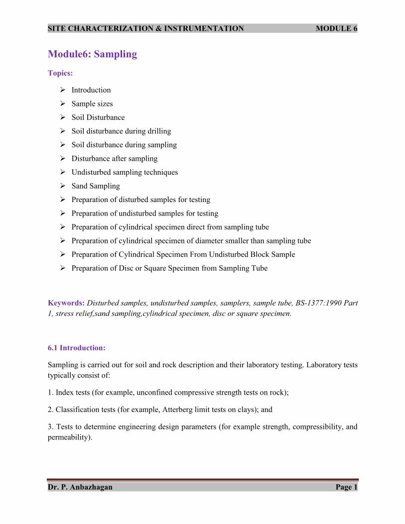
Figure 6.3: Sampler assembly and details of cutting shoes
When driving sample tubes into the ground, by whatever method, it is important to remember
that water (or air) above the top of the sample or piston, contained inside the tube, must be able
to escape without significant increase in occurrence of pressure.
It is normal to provide vents in the top of the sampler, but their size must be limited for reasons
of geometry and sampler strength. Therefore, it is necessary to limit the speed of sampler
penetration. For most samplers a speed of 25mm/s will be satisfactory. Figure 6.3 shows
sampler assembly and details of cutting shoes.

SITE CHARACTERIZATION & INSTRUMENTATION MODULE 6
Dr. P. Anbazhagan Page 16
6.6 Disturbance after sampling:
Changes to the soil after sampling can be at least as severe as those occurring during boring and
sampling. Five major types of change can be recognized:
1. Moisture loss;
2. Migration of moisture within samples;
3. The effects of inadvertent freezing;
4. The effects of vibration and shock; and
5. The effects of chemical reactions.
6.6.1 Disturbance in the soil-testing laboratory:
Even when the utmost care is taken to avoid the serious effects that have been described above, it
is still possible for soil testing to be carried out on disturbed materials, as a result of further
disturbance induced once the sample enters the laboratory. The principal causes of disturbance
are:
1. Poor extrusion practice, either due to high extrusion pressures being applied to unsaturated
soil, or due to lack of proper support of low-strength clays during extrusion;
2. Use of poorly designed tubes to take small-diameter specimens from larger diameter samples;
and
3. Damage to soil ‘structure’ as a result of poor saturation or reconciliation procedures.
6.6.2 Effects of sample disturbance:
The most obvious effect of sample disturbance can be seen when attempting to tube sample very
soft, sensitive clays with a poorly designed sampler. The soil around the edge of the sample
undergoes a very large decrease in strength, such that when the tube is withdrawn from the soil
there is no recovery.
However as it has been noted above, sample disturbance occurs in all sampling processes and if
sampling is carried out well, the effects of disturbance will hopefully be more subtle.
Whatever its magnitude, sampling disturbance normally affects both undrained strength and
compressibility. In addition, chemical effects may cause changes in the plasticity and sensitivity
of the soil sample.

SITE CHARACTERIZATION & INSTRUMENTATION MODULE 6
Dr. P. Anbazhagan Page 17
Bore hole samplers
Drive samplers Rotary samplers
Open drive Piston drive Sliding liners Retracted inner
barrel
Protruding
inner barrel
Retracting
inner barrel
6.7 Undisturbed sampling techniques:
When carrying out site investigation abroad, the available drilling equipment is often very
different from that used at home, and the familiar sampling tools may be either unobtainable or
inappropriate.
When drilling at home the solution of new problems may require a reappraisal of the value of
commonly used techniques.
These factors necessitate the knowledge of various types of samplers being used.
Samples are obtained in a number of ways:
1. By using a number of techniques in shallow pits, shafts and exposures; and
2. In boreholes, using either drive or rotary techniques.
Drive samplers are pushed into the soil without rotation, displacing the soil as they penetrate.
They generally have a sharp cutting edge at their base.
Rotary samplers (often termed ‘core barrels’) have a relatively thick and blunt cutting surface,
which has hard inclusions of tungsten or diamond set into it. The sampler is rotated and pushed
(relatively) gently downwards, cutting and grinding the soil away beneath it. Figure 6.4 shows
general sampling techniques
Figure 6.4: General classification of borehole sampling devices
It is generally believed that undisturbed sampling is not possible in granular soils.
6.7.1 Samples from pits and exposures:
Trial pits, trenches and shallow excavations are often used in site investigations, particularly
during investigations for low- and medium-rise construction, because they provide an
economical means of acquiring a very detailed record of the complex soil conditions which often
exist near to the ground surface.

SITE CHARACTERIZATION & INSTRUMENTATION MODULE 6
Dr. P. Anbazhagan Page 18
The types of samples taken will vary according to the needs of the investigation. Disturbed
samples of granular soil are likely to be more representative than those that can be taken from
boreholes.
Disturbed samples are often taken for moisture content or plasticity determination in the
laboratory, and in association with determinations of in situ density.
Undisturbed samples can be obtained either by drive sampling or block sampling. In either case
it is important to recognize the disturbance created by excavating the trial excavation, and ensure
that disturbed material is carefully removed before or after sampling.
Better quality samples of firm to stiff clay soils can be obtained by trimming the soil in advance
of a large diameter (100—200 mm) sampler.
When the soil is sufficiently stiff or cemented to stand up under its own weight, a block sample
may be taken. The normal technique is to cut a column of soil about 300mm cube, so that it will
fit inside a box with a clearance of 10—20 mm on all sides.
A box with a detachable lid and bottom is used for storage. With the lid and bottom removed, the
sides of the box are slid over the prepared soil block, which is as yet attached to the bottom of
the pit.
After filling the space between the sides of the box and block with paraffin wax, and similarly
sealing the top of the block, the lid is placed on the box. The block is then cut from the soil using
a spade, and the base of the sample trimmed and sealed.
Block samples allow complete stress relief, and may therefore lead to expansion of the soil, but
in very stiff clays, this technique is widely regarded as providing the best available samples.
6.7.2 Drive samplers:
Drive samplers are samplers which are either pushed or driven into the soil without rotation. The
volume of soil corresponding to the thickness of the sampler wall is displaced into the
surrounding soil, which is either compacted or compressed.
Drive samplers can be divided into two broad groups:
1. Open-drive samplers and
2. Piston-drive samplers.
Open-drive samplers consist of a tube which is open at its lower end, while piston drive samplers
have a movable piston located within the sampler tube.

SITE CHARACTERIZATION & INSTRUMENTATION MODULE 6
Dr. P. Anbazhagan Page 19
Piston samplers can be pushed through a soft soil to the desired sampling level, but open-drive
samplers will admit soil as soon as they are brought into contact with, for example, the bottom of
a borehole.
6.7.2.1 Open-drive samplers:
Open-drive samplers can be arbitrarily divided into two groups. Thin-wall open-drive samplers
have been defined as those with a wall thickness of sampling tube of less than 2.5% of the
diameter, corresponding approximately to an area ratio of 20%.
In the following discussion thin-wall sampling devices are taken to be those with an area ratio of
less than 20%, and a suitable cutting shoe taper, while thick-wall samplers are taken to have an
area ratio greater than 20%.
Advantages:
The advantages of open-drive sampling are
principally those of cheapness, ruggedness
and simplicity of operation.
Dis-advantages:
Open-drive samplers suffer from several
disadvantages, as Hvorslev (1949) pointed
out.
1. Poor cleaning of the borehole before
sampling or collapse of the sides of the
borehole after cleaning may mean that much
of the recovered soil is not only highly
disturbed, but also non-representative.
2. The use of a large area ratio can induce soil
displaced by the sampler drive and causing
large-scale remoulding of the sample.
3. The problems of pressure above the sample
during the drive, and of sample retention
during withdrawal.
Figure 6.5: Down-hole block sampler

SITE CHARACTERIZATION & INSTRUMENTATION MODULE 6
Dr. P. Anbazhagan Page 20
Thin-walled open-drive samplers:
The thin-walled open-drive sampler or ‘Shelby Tubing’ sampler was introduced in the USA. The
US Engineer Officeattached the thin-wall sampler tube to the head by spot welding it to a short
length of heavy tube, which in turn threaded into the head.
Another method of fixing the tube to the head uses tubing which is a close fit over the lower
section of the sampler head, and which is fixed to the head by two Allen set screws which, when
engaged, lie flush with the outer surface of the sampler tube. This design has been incorporated
into a large number of samplers, and is now in use worldwide.
They had relatively small area ratios (approximately 10—14%), but had a length to diameter
ratios of 15—20 and did not use inside clearance. The cutting edge was either cut square, or
bevelled.
Thin-walled open-drive sample tubes are readily damaged, either by buckling or blunting or
tearing the cutting edge, when they are driven into very stiff, hard, or stoney soils. Pushing,
rather than hammering, tends to reduce the chances of damaging the tube. When the cutting edge
is damaged, the tube must be sent to the metal workshop for reforming.
In very soft sensitive soils sampling will normally need to be carried out with a piston sampler.
Thin-walled open-drive sample tubes are typically 24—30in. (i.e. 610—762mm) long, and give a
maximum sample length 2—3 in. (52—70 mm) less than this. They may be expected to have an
inside clearance of up to 1— 1%. Available in a wide variety of diameters, they typically have
area ratios similar to those in Table 6.7.
Table 6.7: Thin-walled open-drive sample tubes
Internal tube
diameter(mm)
Area ratio
(%)
Length/diameter
ratio
48 15 11.5
60 13 9.1
73 12 7.5
86 10 6.4
121 8 4.9
It can be seen that for this type of sampler, the 121 mm internal diameter tube provides an
excellent combination of low area ratio and low length to diameter ratio, which would give
acceptable r

SITE CHARACTERIZATION & INSTRUMENTATION MODULE 6
Dr. P. Anbazhagan Page 21

SITE CHARACTERIZATION & INSTRUMENTATION MODULE 6
Dr. P. Anbazhagan Page 22
6.7.2.2 Thick-walled open-drive samplers:
Thick-walled open-drive samplers are widely used throughout the world. In their most common
forms they consist of a solid or split sampler barrel, threaded at both ends to take a cutting shoe
(typically with inside clearance) and a sampler head provided with either a check valve or vents.
Thick-walled split barrel samplers:
A further common sampler is the thick-walled open-drive split barrel sampler. Here the sampler
barrel is split longitudinally into two halves. During driving, these are held together by the shoe
and head which are screwed on to each end.
The split barrel allows easy examination and extraction of the sample, but makes the sampler
considerably weaker. To compensate for this, such samplers are usually short, and have a high
area ratio.
One of the most common thick-walled open-drive split barrel samplers are used during the
Standard Penetration Test which has been described in in-situ testing.Samples of coarse granular
soils must be considered unrepresentative, because the coarser particles will not be able to enter
the barrel during driving.
Because of its design, the SPT thick-wall open-drive split barrel sampler will give low recoveries
in most soils. It is therefore, unsuitable for obtaining continuous representative samples for a
variation or reconnaissance survey.
Samplers using liners inside the sample tube were termed ‘composite samplers’. Liners allow
considerable savings to be made because the structural outer sampler barrel, which transmits the
driving force to the cutting shoe, can be used repeatedly.
Only the liner is removed,complete with sample, and sealed and transported to the laboratory.
Where cohesion less or very soft soils are to be sampled it is, of course, necessary that they are
not removed from the sampler tube before they are to be examined.
Sectional liners can be very useful in reducing the need for a laboratory extruder to remove soil
from the tube, and they also allow the soil to be examined in the field, if necessary. If an extruder
is not required for sample extraction, the liners can be used successfully in a wider range of soils.
Laval sampler:
Probably the most effective tube sampler available for sampling soft and sensitive clays is the
Laval sampler. The use of such an expensive, time-consuming and delicate sampling process for
routine sampling probably cannot be justified.This sampler recovers soft and sensitive soil
almost of the quality that can be achieved using block sampling techniques.

SITE CHARACTERIZATION & INSTRUMENTATION MODULE 6
Dr. P. Anbazhagan Page 23
The device consists of a thin-walled sampling tube mounted on a sampler head, and housed
within an external core barrel. The sampling tube contains a screw-type head valve which
ensures that an effective vacuum can be achieved above the sample during withdrawal from the
ground.
The external core barrel is used to remove soil around the sampling tube, after tube penetration,
to ensure that no vacuum exists at the bottom of the cutting edge during sample withdrawal.
No inside clearance is required because, in the soil types in which it is intended to be used, the
shearing action between the tube and the soil leads to positive excess pore pressures, a reduction
locally in effective stress, and a consequent lubricating effect.
The sampling tube is precision machined from ZW-1035 carbon steel tubing with an inner dia of
200mm and an outer dia of 218 mm, to give a uniform circular internal cross-section along its
length, and an internal diameter of 208 ± 0.03 mm. With a wall thickness of 5mm, the area ratio
is 10% and the B/t ratio is 42. The cutting edge angle is 5°. Figure 6.7 shows photo of Laval
sampler.
Figure 6.7: The Laval sampler (photograph courtesy Dr D.W. Hight)

SITE CHARACTERIZATION & INSTRUMENTATION MODULE 6
Dr. P. Anbazhagan Page 24
The operation of the device is as follows.
A borehole is made to the required depth, either open-hole using a fishtail bit, or as a result of
previous sampling. No casing need normally be used, since bentonite mud flush provides wall
support.
The sampling assembly is lowered to the bottom of the hole with the sampler hooked on to the
collar inside the top of the core barrel. With the head valve open, the sampling tube is gently
unhooked by lifting and turning the inner rod on the surface.
The sampler is pushed slowly into the soil, stopping some 50mm before contact is made between
the bottom of the sampler head and the upper surface of the soil. The head valve is then closed,
and the core barrel is used in conjunction with mud flush to clear soil from around the outside of
the sampler tube, and to a depth of approximately 20mm below the bottom of its cutting edge.
The sample tube is rotated through about 90° in order to shear the soil at its base, and is then
pulled gently out of the soil and hooked back onto the internal collar. The assembly is finally
removed from the borehole.
The sample is extruded immediately, and is cut into slices 130mm or 200mm high which is
placed on waxed plywood board and sealed in several layers of Saran paper sandwiched between
brushed paraffin wax/Vaseline mixtures. The cost of the steel sampling tubes is such that they
cannot economically be used for sample storage. Typical Laval 200 mm diameter sample is
shown in Figure 6.8.
6.7.3 Piston drive samplers:
Piston samplers have a piston contained within the sample tube, which is moved upwards
relative to the sample tube at some stage of the sampling process.
The pistons have been included in sampler designs in order:
1. To prevent soil entering the sampler tube before the sampling position is reached.
2. To reduce losses of samples by providing an efficient airtight seal to the top of the soil in the
tube during withdrawal. Any tendency of the sample to slide out of the tube is counteracted by a
pressure decrease above the sample.
3. To reduce the entry of excess soil into the tube during the early stages of sampling, as a result
of using a relatively high area ratio, and to prevent too little soil entering the sampler at the end
of the drive, as a result of the build-up of internal friction; and

SITE CHARACTERIZATION & INSTRUMENTATION MODULE 6
Dr. P. Anbazhagan Page 25
Figure 6.8 The Laval 200mm diameter tube sampler
4. To increase the acceptable length to diameter ratio, adhesion between the tube and the soil
entering is increased? This will tend to reduce recovery once large length/diameter ratios are
reached, but the movement of the top of the sample away from the underside of the piston will
form a vacuum which will tend to increase the recovery.
Hvorsle defined three main groups of piston sampler:
(i) Free piston samplers;

SITE CHARACTERIZATION & INSTRUMENTATION MODULE 6
Dr. P. Anbazhagan Page 26
(ii) Retracted piston samplers; and
(iii) Fixed piston samplers.
6.7.3.1Free piston samplers:
Free piston samplers have an internal piston which may be clamped during withdrawal of the
sampler, and during driving of the sampler to the required sampling depth. However, when the
sample tube is being pushed into the soil during sampling the piston is free to move both with
respect to the sample tube and to ground level.
Figure 6.9 shows the Ehrenberg piston sampler and the Meijn piston sampler. In the former, the
piston is free to move upwards at all times, but it cannot move downwards relative to the sample
tube. It is not suitable for pushing through soft soil in order to reach the desired sampling level.
Figure 6.9: Two types of free piston sampler
(a) Meijn Sampler (a) Ehrenberg Sampler

SITE CHARACTERIZATION & INSTRUMENTATION MODULE 6
Dr. P. Anbazhagan Page 27
In contrast, the Meijn sampler holds the piston at the bottom of the sample tube with two lugs on
the inner rod which locate below a grooved collar in the sampler head. When the sampler reaches
the correct level the sampler head and tube are rotated through 90° and the lugs clear the collar.
After pushing the sample tube into the soil, loss of material is prevented during withdrawal by a
cone clamp in the sampler head which prevents the piston rod sliding downwards through the
head.
Free piston samplers overcome most of the disadvantages of the open-drive type of sampler, but
they remain easy to use.
Their main advantages are that they can be designed so that they can be pushed through debris at
the base of a borehole, and that sample loss is greatly decreased by the provision of an efficient
seal at the top of the sample.
6.7.3.2Retracted piston samplers:
Retracted piston samplers use the piston primarily to prevent the entrance of unwanted soil
during the process of pushing the sampler to the required sampling depth. Once this depth is
reached the piston is retracted to the top of the tube, and the sampler is then driven into the soil.
The retraction of the piston may cause soft soil to flow upwards into the tube, and during driving
a large area ratio may lead to the entry of excess soil into the tube. It retains several of the
disadvantages of the open-drive sampler, and is more difficult to use.
6.7.3.3Fixed piston samplers:
Fixed piston samplers can be used with or without a borehole. The sampler is pushed to the level
at which sampling is to start with the piston rod fixed relative to the sampler head and tube, and
located at the base of the tube to prevent the entry of soil. Figure 6.10 shows thin-walled
seamless steel tube fixed piston sampler
At this point the piston is freed at the sampler head, but re-fixed at the ground surface to the
drilling rig or to a suitable frame in order to prevent it moving vertically during sampling. The
sample tube is then pushed ahead of the piston into the soil.
After sample driving, the inner rods extending to the ground surface from above the sampler
head can be removed, since the piston is prevented from moving downwards relative to the
sample tube by a clamp located in the sampler head.
Fixed piston samplers have the following advantages:
1. They prevent the entry of debris before sampling
2. They reduce the entry of excess soil during sampling and

SITE CHARACTERIZATION & INSTRUMENTATION MODULE 6
Dr. P. Anbazhagan Page 28
3. They largely eliminate sample losses.
Its disadvantages lie principally with
its cost and complexity in use.
Piston samplers with fixed pistons are
available with a variety of sampler
barrels. These may be thin-walled
(made of either seamless steel tubing or
of aluminium tube) or of the composite
type.
A thin-walled seamless steel tube type
fixed piston sampler similar to those
described by Hvorslev (1949). The
sampling tube has a rolled and reamed
cutting edge. The sampler may be
pushed through soft soils to the desired
sampling level and, during this process,
the conical piston is held at the base of
the sampler tube.
This is achieved by attaching the piston
rod to the upper part of the head via a
few turns of the left-hand thread of the
piston rod screw clamp. When the
sampling level is reached, the piston
rods are turned clockwise at ground
surface, tightening the rods above the
sampler but disengaging them at the
screw clamp.
The piston rod is then fixed to the rig or
a frame at ground level, and the hollow
outer rods are pushed smoothly
downwards to drive the sampling tube
ahead of the piston into the soil.
After sampling, the piston rods can be
unclamped and the sampler pulled to
the surface using the outer rods. The
piston is held up by the ball cone clamp Figure 6.10 Thin-walled seamless
steel tube fixed piston sampler

SITE CHARACTERIZATION & INSTRUMENTATION MODULE 6
Dr. P. Anbazhagan Page 29
in the sampler head. Once the sampler is at ground surface, the tube is released from the head by
screwing the Allen set screws inwards.
The ball cone clamp must be released by turning a screw on the side of the head through 900
before the sample tube can be pulled from the head. The vacuum release screw must be
slackened before the piston can be pulled out of the sample tube. The various screws must be
reset before the next sample is taken.
6.7.4 Foil and stockinette samplers:
According to Broms and Hallen (1971), two types of sampler exist, giving sample diameters of
either 68mm or 40mm. There are sixteen rolls of very thin high strength steel foil in the sampler
head of the 68mm sampler.
Each foil is 12.5mm wide, and about 0.1mm thick. The thickness may be varied depending on
the required maximum sample length and the anticipated frictional forces to be resisted. The
sampler is pushed into the soil without a borehole.
As the sampler is pushed downwards the foils, which are attached to a stationary piston, unwind
from their rolls and completely surround the sample.
The maximum sample length that can be obtained depends on the strength of the foils and the
size of the foils and their magazines. The 40 mm foil sampler can hold a maximum length of 12
m of foil, while the 68 mm sampler can store 30 m.
The friction between the foils and the sampler can be reduced by lubrication when sampling
clays, and it has then been found possible to obtain continuous cores more than 20 m long in
very soft to soft soil. In sands, lubricants may penetrate the soil and cannot therefore be used; the
length of the sample is reduced.
The sampler is generally pushed or driven into soft cohesive soils. When silty or sandy soils are
met, jetting may be needed to reduce the driving resistance. Ramming and jetting reduce the
quality of the sample.
Figure 6.11 shows Principle of operation of the Swedish foil sampler

SITE CHARACTERIZATION & INSTRUMENTATION MODULE 6
Dr. P. Anbazhagan Page 30
Figure 6.11: Principle of operation of the Swedish foil sampler
6.7.5 Rotary samplers:
The main tool used for rotary sampling of hard rocks in the UK and most of the world is the
rotary core barrel but rotary samplers are increasingly being adapted to sample virtually all types
of soil and rock.

SITE CHARACTERIZATION & INSTRUMENTATION MODULE 6
Dr. P. Anbazhagan Page 31
Rotary core barrels designed to sample the harder materials encountered during site
investigations can be classified into three broad groups:
1. Corebarrels with retracted inner barrels, such as the conventional double-tube swivel type core
barrel, here termed ‘retracted core barrels’;
2. Core barrels where the inner barrel protrudes ahead of the outer barrel, in an attempt to protect
the ground being sampled from the deleterious effects of flush fluid, here termed ‘protruding
corebarrels’; and
3. Corebarrels where the inner barrel is spring mounted, so that it protrudes in the relatively soft
ground, but retracts when harder layers are encountered, here termed ‘retractor barrels.
6.7.5.1 Refracted core barrels
Double-tube swivel type core barrels:
The double-tube core barrel contains a stationary inner barrel supported on a swivel. Flush fluid
is pumped down the inside of the rods which run from the drilling rig at ground level to the top
of the core barrel.
Once inside the barrel the flush fluid passes down between the inner and outer barrels and
discharges through ports in the cutting face of the bit. The inner barrel is extended with a core
catcher box which contains a split ring core catcher.
When the barrel is pulled from the bottom of the hole, the catcher spring prevents loss of core by
moving down the inside taper of the catcher box and progressively gripping the core more tightly
if it slips downwards.
Double-tube swivel type core barrels of large diameter can be used with great success not only to
provide a good quality core of sound rock, but also to provide samples of very stiff or hard clays.
Once the core enters the inner barrel it is protected from erosion of the flush water and from the
torsional effects of rotation. The top of the inner barrel is vented to prevent build-up of pressure
over the top of the core.
Should this vent become blocked, the pressure in the inner barrel may prevent core entry after as
little as 0.5 m of coring, and in softer formations the core may be washed away or ground away.
Corebarrels tend to have a larger area ratio and inside clearance than is generally accepted for
drive samplers.
The main disadvantage of the double-tube swivel type corebarrel is that considerable skill and
experience are required to use it successfully. When soil conditions are difficult both equipment

SITE CHARACTERIZATION & INSTRUMENTATION MODULE 6
Dr. P. Anbazhagan Page 32
and technique must be chosen with care: flush fluid, rig stroke, barrel length, diameter and
design, and bit type will all be important.
Much damage can be done to good core during its extraction from the barrel. It is not uncommon
to see core removed by holding the core barrel almost vertical on a wire rope, and repeatedly
hitting the inner barrel with a hammer.
This method is not only likely to damage the inner barrel, but also will often damage the core.
There is little or no chance of the driller being able to maintain the pieces of core in the same
relative orientation as they occupy in the barrel while he struggles to place them in a core-box.
Core should be extruded with the corebarrel held horizontally, using a core-plug in the inner
barrel. Pressure should be smoothly applied to the back of the core-plug so that the core is
extended with a minimum of vibration into a plastic receiving channel of about the same
diameter as the core. After extrusion both core and plastic channel should be wrapped in clear
polythene sheet and securely taped before being placed in the core-box.
It was found that the double-tube swivel type corebarrel gave the best specimens, based on
unconfined compressive strengths and modulus of elasticity values.
6.7.5.2 Protruding core barrels:
In order to reduce the effects of flush fluid and torsional forces on the core, a number of devices
have been developed in which the inner barrel extends below the bottom of the rotating core-bit.
6.7.5.3. Denison core-barrels:
The Denison core barrel is a triple-tube swivel type core barrel, with a shoe with a sharp cutting
edge threaded onto the inner barrel and extending below the cutting teeth of a tungsten core-bit.
The length of the core-bit must be changed to alter the amount by which the shoe extends below
the core-bit.
The Denison core barrel uses a ‘basket’ type spring core catcher, where a number of curved, thin,
flexible springs are fixed to a base ring by rivets, or by welding.
The use of a high area ratio means that samples of hard clays and dense sands or gravels will be
greatly disturbed, and better sampled by a conventional retracted inner barrel type sampler. Very
soft to firm clays can be more effectively sampled with a fixed piston sampler. The Denison
sampler is designed for use in stiff to hard cohesive soils and in the sands.
6.7.5.4 Retractor barrels:
One of the problems facing the Denison core barrel user is that the inner barrel protrusion must
be pre-selected. To overcome this problem, several core barrels have been developed which
include spring mounted inner-barrels.

SITE CHARACTERIZATION & INSTRUMENTATION MODULE 6
Dr. P. Anbazhagan Page 33
6.7.6 Pitcher sampler:
The inner barrel consists of a thin-walled sampler tube with a rolled and reamed cutting edge
which is fixed to the inner head by set screws. The outer barrel has a tungsten insert core-bit. The
inner head is not fixed to the outer barrel.
When the device is lowered to the bottom of the hole and the head is supported immediately
above the bit and flush fluid can be passed down the drill rods through the centre of the sample
tube to remove any debris left at the bottom of the hole.
Once the sample tube beds onto the soil at the bottom of the hole, the central tube on the top of
the inner head mates with the outer barrel head. Flush fluid is now routed via the outside of the
sampling tube, and the space above the sample is vented via the top of the sampler. The lead of
the tube cutting edge is governed by the spring stiffness and the hardness of the soil.
In theory, this type of sampler is ideally suited for drilling in soils with alternate hard and soft
layers. In practice, it has been found that hard friable soils, such as the weathered Keuper marl,
can be sampled very successfully but frequently damages the rather light sampling tube.
Thus, this device is likely to be unsuitable for sampling inter-layered soil and rock, for example
inter-layered clay and limestone.
6.7.7 Maziercorebarrel
The Maziercore barrel is a triple-tube swivel type retractor barrel, whose effectiveness (as with
the Pitcher sampler) relies on the fact that the amount of inner barrel protrusion is controlled by a
spring placed in the upper part of the device.
The inner barrel contains a brass liner which can be used to transport samples to the laboratory,
or for storage. The cutting shoe on the bottom of the inner barrel is substantial, making it much
less easily damaged than a thin-walled seamless tube, but introducing the problems of
disturbance when the high area ratio shoe travels ahead of the core-bit.
Figure 6.12: shows details and detail and principle of operation of the Mazier core barrel
sampler.

SITE CHARACTERIZATION & INSTRUMENTATION MODULE 6
Dr. P. Anbazhagan Page 34
Figure 6.12: Detail and principle of operation of the Maziercore barrel

SITE CHARACTERIZATION & INSTRUMENTATION MODULE 6
Dr. P. Anbazhagan Page 35
6.8 Sand sampling:
Undisturbed sand sampling can be very expensive, and is normally only required in special
circumstances, for example to obtain values of in situ density for earthquake liquefaction
problems or for compressibility studies.
There are a number of techniques for sampling sand using:
1. Thin-wall fixed piston samplers in mud-filled holes;
2. Open-drive samplers under compressed air;
3. Impregnation;
4. Freezing;
5. Core catchers.
6.8.1 Bishop’s sand sampler:
Bishop’s sand sampler consists of a 63.5mm thin-walled open-drive sampler held by set screws
to a head containing a rubber diaphragm check valve and vents. This assembly is mounted within
a compressed air bell which is connected to an air pump at the ground surface. The Bishop
compressed air sand sampler is shown in Figure 6.13.
The sampler is used in the following manner.
1. Lower the sampler inside the compressed air bell to the base of a cleaned borehole.
2. Push the sample tube ahead of the bell into the soil, using the rods.
3. Remove the rods, and force compressed air into the bell via the relief valve in the sampler
head. The relief valve vents to the inside of the bell at a pressure difference of about 150 kN/m2,
and this pressure bears on the upper surface of the diaphragm, ensuring that it works efficiently.
4. Once air bubbles rising to the surface of the water in the borehole indicate that the water in the
bell has been expelled, the sample tube is pulled from the soil into the bell, and then rapidly
brought to ground surface using the lifting cable.
5. Remove the spacer, push the sample tube and head out of the bell, and release the sample tube
set screws.
6. Cap the base of the tube and release the check valve before removing the sample tube from the
head.

SITE CHARACTERIZATION & INSTRUMENTATION MODULE 6
Dr. P. Anbazhagan Page 36
Figure 6.13: Bishop compressed air sand sampler
The Bishop Sand sampler uses arching and the small capillary suctions set up at the sand/air
interface to reduce sample losses.
Soil impregnation:
Van Bruggen (1936) described the use of soil impregnation with a dilute emulsion of asphaltic
bitumen, in order to impart cohesion to granular soils and thus allow them to be sampled. The
bitumen was subsequently removed by washing through with a solution of carbon disulphide and
acetone.
Such a process would certainly change the properties of the soil. The use of chemical injection
around the cutting shoe of an open-drive sampler to solidify soil and help to retain samples of
granular material has been described.

SITE CHARACTERIZATION & INSTRUMENTATION MODULE 6
Dr. P. Anbazhagan Page 37
Subsequently Karol (1970) and Borowicka (1973) have reported the use of various resin and
silica grouts to prevent disturbance to the soil structure during sampling. Impregnation and
injection are expensive and relatively difficult to use.
The soil to be sampled cannot be impregnated unless the chemicals and so on, can be effectively
removed at a later date, and in addition, most grouts and emulsions will not penetrate relatively
impervious sand or silt soils. The method is therefore rarely used.
Freezing:
In contrast, freezing has been widely used to seal the bottom of sample tubes (once driven), to
prevent disturbance to the soil during transporting to the laboratory, and to freeze soil before
sampling.
The value of samples obtained by freezing depends on the amount of density and soil structure
change caused by the process.
The amount of strain taking place, during freezing increases with increase in relative density,
decrease in applied pressure and increase in freezing time.
Core catchers:
Core catchers can be used with great success to retain granular soils, but their design may
introduce considerable disturbance during the sampler drive. Spring systems such as used in
rotary samplers are examples of the types of catching device which should be used with great
caution.
Summary of different sampling methods are given in Table 6.8:
Table 6.8: Summary of Sampling
Soil type Recommended sampling
methods
Likely disturbance
Very soft, soft, firm, or
sensitive clays
Laval open-drive over-cored
sampler
Sherbrooke down-hole block
sampler
Minor destructuring
Reduction in effective stress
due to borehole fluid
penetration
Inter-layered sand, silt, clay Delft sampler Major loss of effective stress.
Some destructuring
Firm, stiff and very stiff
clays
Thin-walled hydraulically
jacked open-drive tube
samples
Minor destructuring, with
significant increases in
effective stress
Very stiff and hard clays,
mudrocks, and stoney clays
Wire-line coring, using
bentonite mud or polymer
muds with anti-swelling
agents, or double-tube swivel
Significant decrease in
effective stress
SITE CHARACTERIZATION & INSTRUMENTATION MODULE 6
Dr. P. Anbazhagan Page 38
type corebarrel with
bentonite mud flush
sand Piston sampling in mud-filled
borehole
Total loss of effective stress.
Major destructuring. Density
approximately maintained
Gravel Sampling from pits Only particle size and density
can be obtained
Weak rocks, chalk Triple-tube swivel-type
corebarrel with mud or msf
flush, or retractor barrel
Minor core loss
Discontinuities opened
Decomposed granite Treifus or Mazier retractor
barrel
Minor core loss.
Effective stress loss
Hard rock Double-tube swivel-type
corebarrel
Discontinuities opened
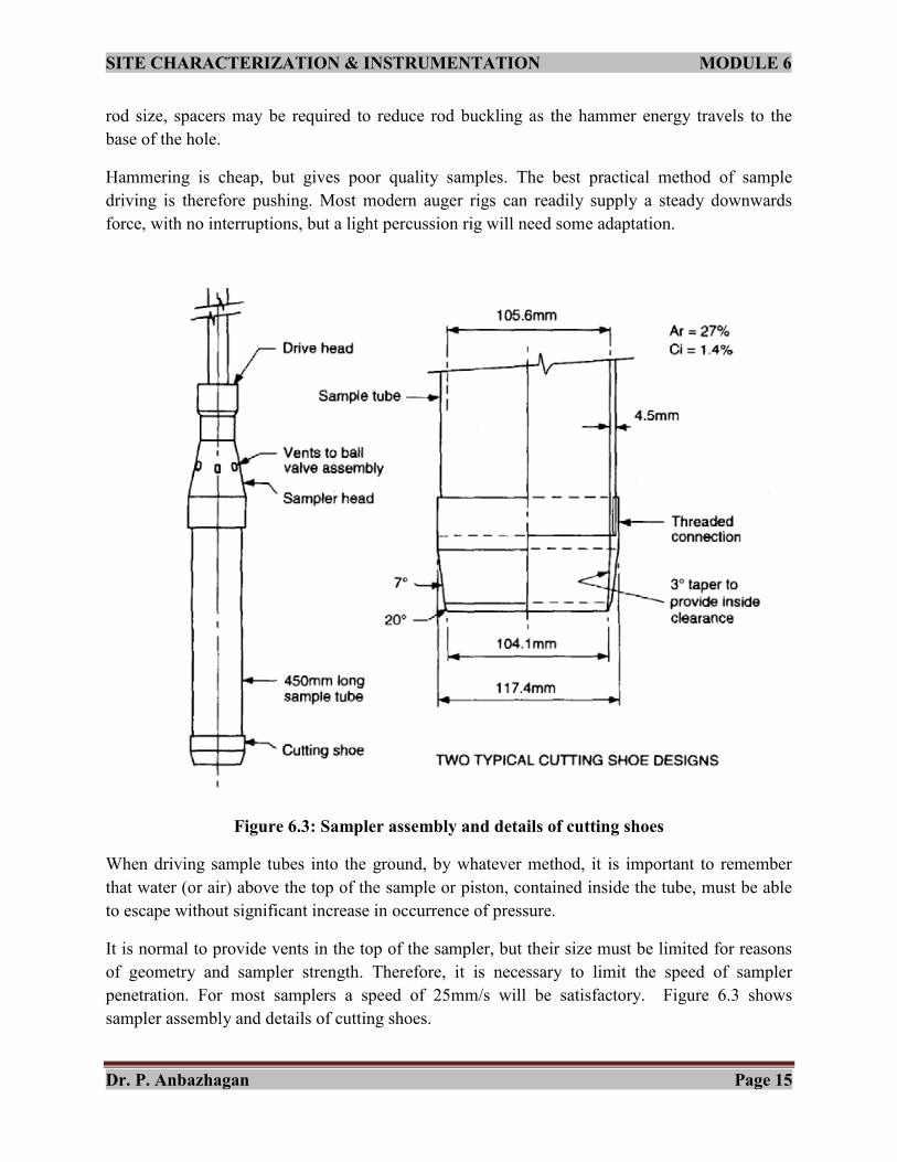
6.9 Preparation of disturbed samples for testing
The steps for the preparation of disturbed samples of soil from the samples received from the field and
their allocation for subsequent tests are described below.The preparation of test specimens of compacted
soil for strength, compressibility and permeability tests is also included.
6.9.1 The apparatus required:
The apparatus required for initial processing of disturbed samples, including drying, disaggregation and
subdivision for testing are described below:
1. A balance of 2Kg capacity, readable to 0.1g
2. A balance of 10Kg capacity, readable to 1g
3. A balance, (e.g. Platform scales) of 25Kg capacity, readable to 5g
4. A mortar and a rubber-headed pestle or a suitable mechanical device which has an action no more
severe than that of a rubber headed pestle.
OR
Any other means of breaking up aggregations of soil without reducing the size of the individual
particles.
5. Test sieves with aperture sizes 425μm, 2mm, 5mm 20mm, 37.5mm and a receiver.
6. Drying ovens capable of maintaining temperatures of 45°c to 50°c and 105°c to 110°c.
7. Sample dividers, e.g. of the multiple-slot type
8. A tray made of corrosion-resistant metal, large enough for mixing the initial soil sample.
9. A metal scoop
10. A palette knife.
11. Watertight corrosion-resistant containers or strong polyethylene bags.
12. An implement for shredding stiff cohesive soil.
13. A cylindrical metal mould, internal volume 1000 (The one-liter compaction mould) with
detachable base plate and extension.
14. A 2.5Kg metal rammer.

SITE CHARACTERIZATION & INSTRUMENTATION MODULE 6
Dr. P. Anbazhagan Page 39
15. A 4.5Kg metal rammer.
16. A cylindrical metal mould of internal diameter 152mm (the CBR mould), with detachable
baseplate and extension.
17. Cylindrical split moulds, fitted with a clamping device capable of holding the component parts
securely together and maintaining the cylindrical shape when the soil is subjected to compaction.
18. A source of vacuum with a connecting length of vacuum tubing.
19. Tamping rod, or spring-loaded tamping device, with a flat circular end of a diameter between
one-third and half of the specimen diameter.
6.9.2 Initial Preparation:
Assessment of soil grouping: An assessment shall be made as to whether the soil is to be classified as
cohesive or cohesionless, and as fine-grained, medium-grained or coarse-grained.
Mass of soil required for testing: The total sample required for testing after assessment sieving
depends on the soil group and the tests to be carried out but to ensure a representative sample the total
mass shall be not less than the following minimum masses:
Fine grained soils 500g
Medium grained soils 5 Kg
Coarse grained soils 30 Kg
The actual mass of sample required shall be assessed by multiplying the mass given in Table 5 of BS
1377-1990 Part 1 (which includes some allowance for drying, wastage and rejection of stones where
required) by the number of test determinations to be carried out. Where the total mass of sample so
calculated is less than the minimum mass given above for the appropriate soil group then that
minimum mass may be taken.

SITE CHARACTERIZATION & INSTRUMENTATION MODULE 6
Dr. P. Anbazhagan Page 40
Table 6.8: Mass of soil samples for each test (adopted from Table 5 of BS 1377-1990 Part 1)
Type of test Laboratory test specification
Soil group
BS 1377: Part number
Sub- clause no.
Fine-grained
Medium- grained
Coarse- grained
Moisture content Saturation moisture content of chalk Liquid limit Liquid limit Liquid limit Liquid limit Plastic limit Volumetric shrinkage Volumetric shrinkage Linear shrinkage Particle density Particle density Particle density Particle size distribution (sieving) Particle size distribution (sieving) Particle size distribution (sedimentation) Particle size distribution (sedimentation)
2 3.2 3.3 4.3 4.4 4.5 4.6 5.3 6.3 6.4 6.5 8.2 8.3 8.4 9.2 9.3 9.4 9.5
50g 350g 4kg
Lump,300mL to 500mL
500g 100g 500g 150g 50g 500g 100g 500g 300g 100g 1.5kg 150g 180g 100g 250g
1kg 200g 1kg 250g 100g 1kg 200g 800g 600g 100g 2kg 2.5kg 2.5kg 250g† 100g†
2kg 400g 2kg 500g 200g 2kg 400g 1.5kg 600g 100g 4kg 17kg 17kg 250g† 100g†
Organic matter content Loss on ignition Sulphate content Sulphate content Carbonate content Chloride content Chloride content Total dissolved solids pH values Electrical resistivity Electrical resistivity Electrical resistivity
3 3.4 4.3 5.5 5.6 6.3 7.2 7.3 8.3 9.3 10.2 10.3 10.4
150g 150g 150g 150g 50g 750g 50g
600g 600g 600g 600g 200g 1.5kg 200g
3.5kg 3.5kg 3.5kg 3.5kg 1.5kg 3.5kg 3.5kg
[About 500mL (water)]
150g 12kg 12kg 8kg
600g 15kg 15kg 10kg
3.5kg 20kg 20kg 15kg
Compaction test* Compaction test* Compaction test* Compaction test* Compaction test*
4 3.3 3.4 3.5 3.6 3.7
25kg (10kg) 80kg (50kg) 25kg (10kg) 80kg (50kg) 80kg (50kg)
25kg (10kg) 80kg (50kg) 25kg (10kg) 80kg (50kg) 80kg (50kg)
25kg (10kg) 80kg (50kg) 25kg (10kg) 80kg (50kg) 80kg (50kg)

SITE CHARACTERIZATION & INSTRUMENTATION MODULE 6
Dr. P. Anbazhagan Page 41
Maximum density Maximum density Minimum density Minimum density Moisture condition value [MCV] MCV/Moisture content MCV rapid assessment Chalk crushing value California bearing ratio
4.2 4.3 4.4 4.5 5.4 5.5 5.6 6.4 7.4
6kg 16kg 2kg 16kg 3kg 6kg 3kg - 6kg
- 16kg - 16kg 3kg 6kg 3kg 2kg 6kg
- 30kg - 30kg 6kg 12kg 6kg 4kg 12kg
Permeability Pinhole erodibility Crumb dispersion Hydrometer dispersion Frost heave*
5 5
5.5 6.2 6.3 6.4 7.3
75mm diameter cell 3.5kg 100mm diameter cell 8kg
300g 50g 500g 80kg (50kg)
† † † 80kg (50kg)
† † † 80kg (50kg)
6.9.3 Moisture content determination:
If the moisture content of the natural soil, as received, is required, representative samples of the
minimum masses given in clause 7.4.2 of BS 1377-1990 Part1 shall be obtained by riffling or
quartering.
Where samples are taken on site for moisture content determination the use of shallow trays for
storing or carrying shall be avoided. The samples shall be kept covered or preferably, sealed when
material is actually being extracted.
Moisture content tests: (Clause 7.4.2 BS 1377-1990 Part 1)
The minimum mass of each category of soil is give below:
Reference in BS 1377:Part 2:1990 Fine grained Medium grained Coarse grained
Oven drying method 20g 300g 3Kg
Saturation moisture content of chalk Lump of 1Kg
Drying of soil: Soil shall be dried by one or other of the following two methods:
a) Oven drying: Drying to constant mass in an oven maintained at a temperature of 105°c to
110°c.
b) Air drying: Partial drying at a temperature not exceeding 50°c. In this method, it shall be
permissible for drying methods to range from exposure to air at room temperature, to partial
drying in a fan assisted oven maintained at a temperature up to 50°c

SITE CHARACTERIZATION & INSTRUMENTATION MODULE 6
Dr. P. Anbazhagan Page 42
When it is necessary to reduce the moisture content to a suitable level for processing, the soil shall be
partially dried at a temperature not exceeding 50°C, unless drying at a higher temperature is specified.
No part of soil shall be allowed to dry out completely.
Exposure to direct sunlight or to infra-red lumps, and the use of a microwave oven, shall be avoided
for soils containing clay or organic matter. When reducing the water content to a desired level, check
weighing shall be made periodically. When it is not practicable to use soil in its natural state the
reason shall be stated and the method of drying shall be reported.
6.9.3 Mechanical Processing:
1) Breaking down of aggregations: After partial drying (if necessary), aggregates of particles
shall be broken down in such a way as to avoid crushing the individual particles. Use an
action that is no more severe than that applied by a rubber pestle. All aggregates of particles
shall be broken down so that when the sample is sieved on the specified test sieve only
individual particles shall be retained.
2) Subdividing: Mix the broken down sample thoroughly and subdivide it by quartering, by
riffling or by other suitable means until representative subsamples of the specified minimum
masses (after suitable further preparation where necessary) are obtained.
6.10 Preparation of Undisturbed samples for testing
Procedures: This section covers the preparation of test specimens from undisturbed samples of soil
received from the field, where the procedure is common to more than one type of test. Procedures that
relate specifically to the preparation of samples for one type of test shall be as given in the relevant
clauses of the appropriate part of the standard BS 1377:1990: Part 1.
Five procedures are described which depend on the type of undisturbed sample and the purpose of the
test specimen, as follows:
a) Cylindrical specimen of the same diameter as the sample tube
b) Cylindrical specimen or set of specimens, of smaller diameter than the sampling tube.
c) Cylindrical specimen from a block sample.
d) Disc or square specimen from a sample in a sampling tube
e) Disc or square section from a block sample
Preservation of samples: Loss of moisture from undisturbed samples shall be prevented during
transportation, preparation and storage.
Tests shall be carried out as soon as possible after sampling, but if longer term storage is necessary,
samples shall be well sealed and stored in a room that is frost free and not subjected to vibration.
Ideally undisturbed samples should be prepared for test, and stored, in an area maintained at a high
relative humidity.
Apparatus:
The following apparatus are common for all the 5 aforementioned procedures.

SITE CHARACTERIZATION & INSTRUMENTATION MODULE 6
Dr. P. Anbazhagan Page 43
1. A sharp thin-bladed trimming knife
2. A scalpel
3. A spatula
4. Two wire-saws, one of piano wire about 0.4mm in diameter and the other a spiral wire-saw.
5. A saw, medium to coarse teeth.
6. A metal straight-edge trimmer, such as a steel strip about 300mm long, 25mm wide and 3mm
thick, with one beveled edge.
7. A straight-edge such as an engineer’s steel rule in good condition, graduated to 0.5mm.
8. A steel try-square
9. Verniercalipers, readable to 0.1mm
10. A flat glass plate, about 300mm square and 10mm thick.
6.11 Preparation of cylindrical specimen direct from sampling tube
When a specimen is to be prepared from an undisturbed sample contained in a tube of the same internal
diameter as the test specimen the procedure shall be as follows. The sample shall normally be pushed out
of the tube in the same direction as it entered. Remove the protective wax and any loose or disturbed
material.
Additional apparatus:
1) An extruder to suit the sampling tube, and to which it can be securely attached during
extrusion.
2) Suitable supports, needed for some soils, to prevent distortion of the sample as it is extruded.
3) A split mould assembly.
Procedure:
1. If the end of the protective coating, e.g. of wax, at the lower end of the sampling tube is
reasonably flat and perpendicular to the axis of the tube, no initial preparation is necessary.
Otherwise remove the protective coating and trim the end of the sample to achieve that condition.
2. Place an oiled paper disc next to the sample, or lightly oil the face of the extruder ram, to prevent
adhesion between the soil and the extruder.
3. Fit the sampling tube on to the extruder and attach the split mould assembly.
4. Extrude enough of the sample out of the tube to enable any loose and disturbed material to be cut
away.
5. Extrude the sample until the length required for testing is contained within the split mould. (Note:
The least disturbed portion of the sample will normally be at the bottom end of the tube, i.e. the
end nearest to the cutting shoe when the sample was taken.)
6. Cut off the surplus soil and trim the ends of the test specimen flat and flush with the ends of the
split mould. Protect the ends from loss of moisture until the specimen is ready to be set up for the
test.
7. Wrap and seal the surplus extruded soil. Extrude, wrap and seal any soil remaining in the
sampling tube, or reseal it inside the tube.

SITE CHARACTERIZATION & INSTRUMENTATION MODULE 6
Dr. P. Anbazhagan Page 44
6.12 Preparation of cylindrical specimen of smaller diameter than sampling tube
This procedure applies to the fine grained cohesive soil which can be extruded into tubes with
negligible disturbance. The procedure shall be used when a specimen, or a set (usually 3) specimens,
is to be obtained from an undisturbed sample of larger diameter than the test specimens. The method
enables a set of specimens to be taken from one depth.
Additional apparatus for this procedure:
1) An extruder
2) Thin walled tube(s) for cutting the test specimen(s). The tubes shall be smooth inside and out and
turned at one end to form a cutting edge at the inner surface of the tube. The area ratio shall be
kept as low as possible consistent with the strength requirements of the specimen tube, and its
value shall not exceed 20%. The length of the tube shall be about 50% greater than the required
length of the specimen.
3) A jig for holding the specimen tube or tubes securely on the sample tube while the sample is being
extruded. The axis of each tube shall be maintained in visual alignment with the direction of
extrusion.
4) An extruder to suit the specimen tube, and to which it can be securely attached during extrusion.
Procedure:
1. Fit the sampling tube on to the extruder. Extrude enough of the sample from the tube to
enable any loose and disturbed material to be cut off, leaving the end of the remaining
sample flat and flush with the end of the tube.
2. Clamp the thin-walled specimen tube or tubes securely in the jig attached to the extruder
with their cutting edges about 10mm away from the end of the sample tube. The axis of
the tubes shall be in alignment with the direction of extrusion.
3. Extrude the sample directly into tubes, maintaining a uniform speed. As extrusion
proceeds cut away excess soil from outside the tubes so that it does not impede the
extrusion.
4. Cut off the extruded soil, remove the specimen tubes from the jog and extrude the
specimen from each tube.
6.13 Preparation of Cylindrical Specimen from Undisturbed Block Sample
Additional apparatus:
1. Thin walled tubes
2. A jig for firmly holding the thin-walled specimen tube in alignment with its direction of
movement as it is pushed into the block sample.
3. A soil lathe.
4. A mitre box.
Procedure:

SITE CHARACTERIZATION & INSTRUMENTATION MODULE 6
Dr. P. Anbazhagan Page 45
1. Cut away about 10mm from the outside of the block sample, and cut on an approximately
rectangular prism of soil slightly larger than the final dimensions of the specimen. The
orientation of the axis of the prism shall be appropriate for the test to be carried out, when
necessary, and shall be recorded.
2. Make the ends of the prism plane parallel using the meter box or by carefully trimming and
checking with a straight-edge and try-square on the glass plate.
3. Use of soil lathe:
Place the specimen in a soil lathe and cut off the excess soil in thick layers. Rotate the
specimen between each cut until a cylindrical specimen is produced. Take care to avoid
disturbance due to torsional effects.
Remove the specimen from the soil lathe. Cut to the required length and make the ends plane
and normal to the specimen axis to within ½”.
4. Use of tube with cutting edge:
Clamp the thin-walled tube firmly in a holding jig.
Push the tube steadily into the soil, carefully trimming away most of the excess soil for a
short distance in advance of the cutting edge. Ensure that the cutting edge itself always pares
away the final silver of excess material so that voids are not formed inside the tube. Maintain
alignment of the axis of the tube with the direction of motion during this operation.
When the tube contains a length of specimen slightly in excess of the required trimmed
length, undercut the specimen so that the tube can be extracted.
Remove the specimen from the tube and trim.
5. Encapsulation:
With brittle soils for which the preceding methods are not practicable, the following method
may be satisfactory. It can be used for an irregular lump of material as well as for a
cylindrical or rectangular shape.
Method:
Cover the piece of soil with paraffin wax, or wrap with thin clinging film, to provide a
waterproof coating.
Place the sample in a container, and surround it with a suitable plaster, mixed with water to a
workable paste, so that the sample is completely encapsulated. Alternatively, pack damp sand
around the sample.
Allow the plaster to set, but not to harden.
Jack a sampling tube with a sharp cutting edge into the encapsulated sample with a
continuous steady movement.
Remove the sample from the tube and trim it.
6.14 Preparation of Disc or Square Specimen from Sampling Tube:
This procedure is used for preparing either a square cylindrical specimen for a consolidation test or
swelling test in an oedometer, or a square specimen for a direct shear test in a small shearbox
apparatus. The mould with a cutting edge into which the specimen is intruded is referred to as the
cutting ring, whether it is circular or square.

SITE CHARACTERIZATION & INSTRUMENTATION MODULE 6
Dr. P. Anbazhagan Page 46
Additional apparatus:
1. A metal cutter for holding or forming the test specimen, provided with a cutting edge. The
cutter shall be circular or square in plan, depending on the type of test.
2. A jack and frame suitable for extruding the soil vertically from the sampling tube.
3. A jig for holding the circular or square cutter just above the top of the sampling tube. The
jig shall be designed to allow the sample to pass through and project above the cutter.
Alternatively a separate driving ring may be used for the same purpose.
Procedure:
1. Fit the sampling tube onto the extruder. Extrude enough of the sample from the tube to
enable any loose and disturbed material to be cut off, leaving the end of the remaining
sample flat and flush with the end of the tube.
2. Extrude a further short length, e.g. 20mm to 30mm, of the soil sample from the tube for
examination, after removing the protective covering.
3. Cut off and remove the extruded length of sample. Trim the end of the remaining sample
flat and flush with the end of the tube.
4. Secure the cutting ring rigidly in the jig and mount the assembly on the sample tube so that
the cutting edge of the ring is 3mm to 6mm above the top of the tube.
5. Extrude the sample steadily directly into the cutting ring until the top surface projects
slightly above the ring. During this operation trim away the soil from the outside of the ring
to reduce friction and to prevent obstruction.
6. Cut off the sample in its ring a little below the cutting edge of the ring and remove the ring
from the jig. With very soft soils take care to ensure that the specimen does not slide in, or
fall out of, the ring.
7. Cut off the soil projecting above the upper end of the ring and trim the surface flat and flush
with the ring, checking with the reference straight edge. Avoid excessive remoulding of the
surface.
8. Place the trimmed surface on the flat glass plate and trim the other surface flush with the
cutting edge. Ensure that no soil is left adhering to the outside of the ring.
9. If the during the above operation a small inclusion interferes with extrusion and trimming,
remove it and fill the cavity with fine material from the parings.
6.15 Preparation of Disc or Square Specimen from Block Sample:
This procedure is used for preparing a test specimen from an undisturbed sample received in the form
of an excavated block, and may also be used for a sample that has been extruded from a sampling
tube. The mould with a cutting edge into which the specimen is intruded is referred to as the cutting
ring, whether it is circular or square.
Procedure: (Using a holding jig)
1. Clamp the cutting ring firmly in the holding jig.
2. Push the ring steadily into the short distance in advance of the cutting edge. Ensure that the
cutting edge itself always pares away the last silver of excess soil so that voids are not formed

SITE CHARACTERIZATION & INSTRUMENTATION MODULE 6
Dr. P. Anbazhagan Page 47
inside the ring. Maintain the plane of the ring at the right angles to the direction of motion
during this operation.
3. When the top surface of the specimen protrudes slightly above the ring, seer the soil slightly
below the cutting edge so that the soil contained in the ring can be removed intact.
4. Trim the specimen.
5. If during the above operation a small inclusion interferes with extrusion and trimming, remove
it and fill the cavity with fine material from the parings.
Procedure: (Using a driving ring)
1. Cut a roughly circular or square portion of soil from the sample of dimensions somewhat
larger than the test specimen.
2. Prepare two plane faces on the portion so that they are flat and parallel to each other and
oriented in the direction required for the test.
3. Place one prepared surface of the sample on the glass plate. Use the ring placed on the exposed
face as a template while carefully trimming the edges of the sample. Push the ring down
slowly and evenly without tilting, using a driving ring placed on top, allowing the cutting edge
to pare away the last fraction of soil. Ensure that the specimen is a close fit in the ring with no
voids against the inner surface. Push the ring down until the top surface of the specimen
projects slightly above it.
4. Remove the driving ring and trim the top and bottom surface of the specimen flat and flush
with the ring.
5. If a small inclusion interferes with the above trimming operations, remove it and fill the cavity
with fine material from the parings.