Embed Size (px)
Citation preview

SISTEMA AQUA
“ADVANCED QUALITY ASSURANCE”
PER IL
CENTRO NAZIONALE DI ADROTERAPIA ONCOLOGICA
Radiografia per assorbimento di protoni
(Proton Range Radiography – PRR)
Tomografia per Diffusione Nucleare e Ricostruzione dei Vertici di Interazione
(Nuclear Scattering Tomography – NST
Interaction Vertex Imaging - IVI)
PET-sul-fascio con Rivelatori Gassosi
(in-beam-PET with Gas Detectors)
PET-sul-fascio con Rivelatori a Cristalli
(in-beam-PET with Crystal Detectors)
Documento preparato dalla Fondazione TERA
15 febbraio 2008

2

3
RIASSUNTO OPERATIVO
Nel maggio del 2006 la Fondazione CNAO ha affidato a TERA lo studio preliminare di un
sistema di PET-sul fascio di cui dotare eventualmente una o più sale di trattamento del Centro
di Pavia in modo da poter controllare sessione per sessione la localizzazione della dose
depositata dal fascio di ioni carbonio. Lo studio prevedeva la stesura di un rapporto
intermedio, che è stato distribuito il 15 novembre 2006. Questo documento descrive il lavoro
fatto sino ad allora ed illustra le scelte tecniche a cui si era giunti.
Nel corso di questo primo studio, oltre alla prevista in-beam-PET (PET-sul-fascio) furono
esaminate due altre possibili metodiche di diagnostica sul fascio che, per quello che si sa, non
sono utilizzate dai gruppi che si occupano di adroterapia:
A) la “radiografia a diffusione nucleare” (oggi ribattezzata NST = Nuclear Scattering
Tomography)la cui fattibilità fu dimostrata da G. Charpak, F. Sauli e collaboratori molti
anni fa; in questo caso si utilizza un fascio di protoni da 1000 MeV, che può essere
prodotto dal sincrotrone del CNAO e che, attraversando il corpo del paziente, permette di
ricostruire dai protoni diffusi una immagine accurata e tridimensionale degli organi del
paziente disteso sul lettino prima del trattamento;
B) un nuovo approccio alla determinazione del percorso degli ioni carbonio nel tessuto
irradiato basato sulla rivelazione delle particelle che, strappate dagli ioni e dai loro
secondari ai nuclei della materia, fuoriescono dal corpo del paziente; questa tecnica è
stata chiamata IVI = Interaction Vertex Imaging. Come previsto nella Convenzione
firmata da CNAO e TERA, i risultati ottenuti hanno permesso di individuare i prototipi di
rivelatori che è necessario costruire e provare nei prossimi sei mesi per giungere, se i
risultati saranno positivi, a una scelta del sistema definitivo da sottoporre alla CNAO per
l’approvazione, il finanziamento, la costruzione e l’installazione in una delle sala di
trattamento.
Il documento fu esaminato dal Consiglio Tecnico Scientifico della CNAO nella seduta del 21
dicembre 2006, che accettò la proposta di proseguire nell’approfondimento dello studio non
soltanto della PET-sul-fascio, ma anche delle altre due tecniche.
All’inizio del 2007 TERA ha stretto una collaborazione scientifica con il gruppo del Prof.
George Chen del Massachusset General Hospital, che ha come scopo la progettazione e la
realizzazione di un sistema di radiografia con protoni, da utilizzare possibilmente prima di
ogni sessione di adroterapia per fare una proto-radiografia del paziente già allineato sul fascio
di ioni carbonio o di protoni. e ricostruire con precisione, prima del trattamento, la posizione
e la dimensione degli organi bersaglio e degli organi a rischio
Nel progetto TERA sono usate due camere GEM e un telescopio di range di 1-2 mm di
risoluzione spaziale, che costituiscono il PRT (Proton Range Telescope). A questo technica è
stato dato il nome PRR = Proton Range Radiography.
Il PRT è fatto di scintillatori di circa 10x10 cm2 registrati singolarmente che hanno uno
spessore compreso tra circa 3 mm. Si vuole ottenere una risoluzione sul percorso dell’1%
circa. La lettura delle due camere GEM da 10x10 cm2 deve essere molto rapida se la proto-
radiografia deve essere fatta in situ in una frazione di minuto. Attualmente non esistono
circuiti elettronici in grado di far questo, e la proposta avanzata da TERA alla CNAO nel
rapporto del 24 aprile 2007 indicava le possibili linee di sviluppo.
Nello stesso rapporto si metteva in luce che, durante la fase di messa in funzione del
sincrotrone e dei sistemi di distribuzione della dose, un sistema costituito da un telescopio di
percorso e due camere GEM sarà molto utile per avere informazioni on-line sulle

4
caratteristiche dei fasci di protoni e di ioni carbonio prodotti dall’acceleratore. Può trattarsi di
un sistema elettronicamente più lento, in quanto l’intensità del fascio può essere ridotta senza
perdere la possibilità di ricostruire in tempo reale l’immagine della distribuzione di dose
tridimensionale e vedere come si comporta non soltanto l’acceleratore, quando si cambia
energia, ma anche il sistema di magneti di “scanning” che deflettono trasversalmente il
fascetto.
La Fondazione CNAO ha accettato la proposta, tenuto anche conto del fatto che non
comporta costi superiori a quelli previsti dall’accordo iniziale. Si sono invece allungati i
tempi, dato che tre altri progetti si sono aggiunti alla PET-sul-fascio.
* * *
La figura rappresenta schematicamente la disposizione, nel piano verticale che passa per il
fascio, degli strumenti discussi in questo rapporto.
Qui di seguito sono riassunti i principali argomenti trattati e le conclusioni raggiunte.
1) Il Capitolo 1 è dedicato alla PRR, il cui interesse clinico è discusso sulla base della vasta
esperienza di George Chen e del suo gruppo, che propone l’uso di un blocco di
scintillatore. La tecnica scelta da TERA è più moderna, in quanto basata su due (o tre)
camere a gas di tipo GEM (un rivelatore rapido e preciso inventato da Fabio Sauli) e su
un insieme di scintillatori sottili visti da nuovissimi Silicon Photo-Multipliers (SiPM).
L’insieme costituisce un Proton Range Telecoppe (PRT).
Dopo aver verificato i risultati ottenibili facendo uso di una simulazione Monte Carlo
basata sul codice standard CERN detto Geant4, si è passati alla realizzazione del sistema.
Le foto mostrano la prima GEM costruita e gli elementi del telescopio di percorso: uno
scintillatore di 3 mm di spessore, una barretta di Wave Light Shifter e un SiPM).

5
Il telescopio di percorso sarà completato entro l’estate e portato a Pavia in tempo per la
prima estrazione dei fasci di protoni e ioni carbonio dal sincrotrone del CNAO.
2) Nel Capitolo 2 è discusso lo strumento utilizzato per la simulazione dei processi fisici
che sono alla base delle tecniche discusse nel seguito. Dopo una breve descrizione di
Geant4 e dei suoi modelli, i risultati ottenuti sono confrontati con dati sperimentali in
modo da validare i modelli stessi. La seconda parte del Capitolo è dedicata agli strumenti
informatici sviluppati per la tecnica della in-beam-PET. In particolare sono descritti i
risultati ottenuti simulando la produzione di emettitori di positoni da parte di ioni
carbonio. Dal confronto dei risultati ottenuti con i dati sperimentali riportati in letteratura
si può concludere che i codici ora a disposizione sono non soltanto sufficientemente
accurati ma, in alcuni casi, più vicini alla realtà di quelli impiegati dal gruppo del GSI di
Darmstadt, che nel campo della PET-sul-fascio ha un’esperienza decennale.
3) Le tecniche IVI ed NST sono discusse nel Capitolo 3. Esse sono trattate insieme in
quanto utilizzano la stessa strumentazione: due telescopi costituiti di camere GEM di
30x30 cm2, scintillatori e assorbitori. La differenza è che per NST i due telescopi sono
usati in coincidenza, mentre per IVI funzionano in singola. Se i calcoli qui presentati
saranno confermati dai risultati che si conta di ottenere nel 2009 utilizzando un sistema
prototipo NST nell’area sperimenentale del CNAO a Pavia, inviando prima di un
trattamento con ioni carbonio un fascio di protoni da 700-800 MeV sarà possibile rivelare
gli eventi di diffusione elastica dei protoni sui nuclei di idrogeno dei tessuti. Si
otterranno, in qualche decina di secondi e prima che inizi il trattamento, informazioni
analoghe a quelle che si hanno con una Risonanza Magnetica, informazioni che sono
diverse e complementari di quelle ottenute con i raggi X.
4) Il Capitolo 4 è dedicato al disegno e alle proprietà che deve avere il rivelatore per la in-
beam-PET che TERA intende realizzare per la Fondazione CNAO. La geometria del
rivelatore è discussa con particolare attenzione al problema delle ‘collisioni’ tra le teste
del rivelatore, il sistema di monitoraggio del fascio e il lettino del paziente. Poi il sistema
di acquisizione dei dati, che è particolare per la CNAO per via l’estrazione lenta fatta con
il metodo del “betatron core”, è analizzato sulla base di un piano di trattamento preparato
da F. Bourhaleb.
5) Il rivelatore a cristalli di tipo LYSO proposto è descritto nel Capitolo 5. I calcoli e le
misure effettuate su cristalli di questo tipo sono riportate dopo la descrizione
dell’utilizzazione fatta del codice LITRANI, che è stato utilizzato per la simulazione del
trasporto della luce in questo nuovo tipo di rivelatore. Si è scelto di simulare con un
Monte Carlo apposito e poi provare sperimentalmente un blocco di cristallo di 12x30x60
mm3, letto analogicamente dal fotomoltiplicatore multianodo mostrato in figura.
In futuro si pensa di utilizzare gli stessi Silicon PhtoMultiplies (SiPM) impiegati nel
telescopio di percorso per la PRR.

6
Questa tecnica non permette risoluzioni spaziali molto spinte, ma ciò in questo caso non è
necessario perché l’attività indotta dal fascio di ioni carbonio nel corpo del paziente è
bassa (circa 200 becquerel per cm3 per gray); le fluttuazioni statistiche quindi dominano e
risoluzioni spaziali dell’ordine di 5 mm sono sufficienti quando si tratta di una in-beam-
PET, una situazione molto diversa da quella che si ha in una PET per animali, che
richiede risoluzioni dell’ordine del millimetro. La dettagliata simulazione ha dato risultati
più che soddisfacenti e i risultati sperimentali li hanno sostanzialmente confermati, pur
con alcuni peggioramenti che sono fisiologici quando si passa dal mondo della
simulazione alla realtà..
6) Il Capitolo 6 è dedicato all’utilizzazione di rivelatori a gas del tipo RPC (Resistive
Plate Chambers) per la in-beam-PET della CNAO. Vi si descrive l’originale soluzione
proposta, che si basa sull’uso di elettrodi di vetro sui quali è depositato un sottile strato di
diamante artificiale che ha una resistività controllata a evitare il caricamento degli
elettrici quando i flussi di particelle sono elevati. La soluzione GEM è anche discussa ed
attualmente è seguita dal gruppo Gas Detector Developments (GDD) del CERN, con cui
TERA collabora.
* * *
Il compito affidato a TERA dalla CNAO nel 2006 concerneva un sistema in-beam-PET utile
per la verifica della localizzazione della dose nei trattamenti con fascetti di ioni carbonio. Nel
corso dello studio sono state individuate altre possibilità di controllo della posizione degli
organi interni del paziente allineato sul fascio e della distribuzione della dose impartita.
Nasce quindi spontanea l’idea di proporre la progettazione e la prova sul fascio di prototipi di
un sistema integrato di rivelatori nel quadro di un programma di controllo della qualità dei
trattamenti, a cui è stato dato il nome di AQUA = Advanced QUality Assurance. Come
primo passo, si tratta di realizzare i prototipi di tutti i rivelatori necessari per applicare le
tecniche PRR, IVI, NST, in-beam-PET rappresentate nella prima figura.
Se le possibilità di controllo della localizzazione degli organi da irradiare e della dose
impartite, descritte in questo rapporto, saranno confermate da dati sperimentali raccolti sul
fascio sperimentale del CNAO, sarà poi possibile decidere quali e quanti di questi strumenti
andranno costruiti.
La proposta AQUA è contenuta in un altro documento preparato per la Fondazione CNAO.

7
TABLE OF CONTENT
INTRODUCTION………………………………………………………………………. 9
1. PROTON RANGE RADIOGRAPHY
1.1 Introduction………………………………………………………………….. 11
1.2 Clinical aspects ……………………………………………………………. 11
1.3 Proton Range Telescope…………………………………………………....... 15
1.4 Performance studies………………………………………………….............. 16
1.1 Prototypes and tests……………………………………………..18
2. VALIDATION OF THE GEANT4 CODE AND IN-BEAM-PET CALCULATIONS
2.1 Introduction…………………………………………………………………… 21
2.2 Interactions of charged hadrons in matter……….…………………………… 21
2.3 Review of Monte Carlo codes available for medical applications…….……... 25
2.4 The Geant4 toolkit…………………………………………………………….. 27
2.5 Physics validation of the electromagnetic processes………………………..… 32
2.6 Physics validation of the hadronic processes…………………………………. 36
2.7 Positron emitters distributions in tissue-like media………………..…………. 43
2.8 Discussion of the results………………………………………………………. 46
3. INTERACTION VERTEX IMAGING AND NUCLEAR SCATTERING
TOMOGRAPHY
3.1 Introduction…………………………………………………………………… 49
3.2 Interaction Vertex Imaging (IVI)……………………………………………... 49
3.3 Nuclear Scattering Tomography (NST)………………………………………. 54
3.4 Detectors for proton tracking…………………………………………………. 59
4. GEOMETRY AND UTILIZATION OF AN IN-BEAM-PET SYSTEM FOR CNAO
4.1 Introduction………………………………………………………………….... 65
4.2 Requirements for an in-beam-PET for CNAO………………………………... 65
4.3 Optimization of the in-beam-PET geometry for CNAO……………………… 66
4.4 Background particles in a in-beam-PET system……………………………… 71
4.5 Materials and methods for sensitivity assessment……………………………. 73
4.6 Validation of the HiRez system……………………………………………….. 77
4.7 Simulation of the hadrontherapy treatment acquisition………………………. 78
4.8 Discussion of the results.... …………………………………………..... 83
8
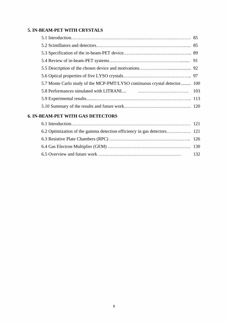
5. IN-BEAM-PET WITH CRYSTALS
5.1 Introduction…………………………………………………………………… 85
5.2 Scintillators and detectors…………………………………………………….. 85
5.3 Specification of the in-beam-PET device……………………………………... 89
5.4 Review of in-beam-PET systems…..……………………………………........ 91
5.5 Description of the chosen device and motivations…………….….................... 92
5.6 Optical properties of five LYSO crystals……………………………………... 97
5.7 Monte Carlo study of the MCP-PMT/LYSO continuous crystal detector......... 100
5.8 Performances simulated with LITRANI.... …………………………… 103
5.9 Experimental results.........…………………………………………………….. 113
5.10 Summary of the results and future work…………………………………….. 120
6. IN-BEAM-PET WITH GAS DETECTORS
6.1 Introduction…………………………………………………………………… 121
6.2 Optimization of the gamma detection efficiency in gas detectors……………. 121
6.3 Resistive Plate Chambers (RPC) …………………………………………….. 126
6.4 Gas Electron Multiplier (GEM) ……………………………………………… 130
6.5 Overview and future work ……………………………………………… 132

9
INTRODUCTION
In May 2006 the CNAO Foundation gave to TERA the responsibility of studying a in-beam-
PET device to be eventually built and used in one of the treatment areas of the Pavia centre.
This technique allows the in situ determination of the spatial distribution of the positron
emitting isotopes produced in the patient body by the carbon ion beam, and can also be
applied when protons are used. It has been pioneered by the Dresden group of W. Enghardt,
who built for the GSI project a device based on conventional PET detectors. The results
obtained on many hundreds patients are very encouraging: few minutes after the end of a
carbon ion treatment the localization of the delivered dose can be determined with an
accuracy of about 1 mm.
During the first part of this study, described in the intermediate report presented on 21
December 2006 to the CNAO Technical and Scientific Committee (CTS), TERA came to the
conclusion that two other techniques were worth investigating. They have been called IMI
(Interaction Vertex Imaging) and NST (Nuclear Scattering Tomography). They use gas
detectors of the GEM type placed at about 45° with respect to the beam and determine the
direction of the charged particles coming out of the patient body.
In IVI, during a carbon irradiation the on-line reconstructed points of interactions of the
outgoing tracks with the incoming pencil beams allows a continuous check of the irradiation
conditions. In NST a 700-800 MeV proton beam is sent, for a short time before the treatment,
along the path of the carbon beam employed for the irradiation and the proton-proton
scattering events are used to image the hydrogen distribution in the patient body. It has to be
remarked that new very fast electronics has to be developed for this device.
These ideas, only sketched in the intermediate report, have been further developed and are
the subject of Chapter 3 of this final report.
At the beginning of 2007 TERA decided o collaborate with G. Cheng of Massachusetts
General Hospital on another diagnostic technique, which is here called PRR (Proton Range
Radiography). In this case, before or after a treatment, a Proton Range Telescope (PRT)
measures the residual range of the protons having enough energy large enough to cross the
patient body. The reconstructed “radiograph” gives direct information on the integral of the
electron density along the protons path.
In April 2007 TERA proposed to CNAO to build a prototype of such a device underlining
that it will be extremely useful in the commissioning phase of the Pavia centre since, placed
at the end of a beam transport line, will allow the operator to “see” the build-up of the dose
distribution obtained with the raster technique. Also in this case new very fast electronics has
to be designed and built for the final device.
CNAO agreed with the proposal of constructing the proton telescope. The status of the
prototype, which will be ready in summer 2008 and brought to Pavia, and the plans for the
implementation of the PRR technique are described in Chapter 1.
If CNAO accepts the continuation of the TERA study and the construction of the prototypes,
these three devices could complement the information provided by the in-beam-PET system.
Four Chapters of this report concentrate of the in-beam-PET technique.

10
Chapter 2 is devoted to the description of the tests and the modifications made to the CERN
Monte Carlo code Geant4, which has been used to compute backgrounds and performances
of all the devices, including the in-beam-PET systems.
In Chapter 4 the geometry of the CNAO in-beam-PET system and its utilization with the
peculiar very stable hadron beam are discussed.
Finally Chapter 5 and Chapter 6 describe in detail the status of the computational and
experimental work which has been done on PET systems since the intermediate report. The
first one is devoted to the development of a new crystal detector and the second one discusses
the use of gas chambers.
* * *
As a consequence of the work done till now, TERA will propose to CNAO the launching of a
project of Advanced QUality Assurance = AQUA, which will built prototypes of the
instruments needed for the four techniques PRR, IVI, NST and PRR. These prototypes will
be tested in the CNAO experimental area starting form fall 2008.
The proposal is described in another document submitted to the CNAO Foundation.

11
1. PROTON RANGE RADIOGRAPHY
1.1 Introduction
Pioneered in the eighties1 proton radiography, which exploits the information of energy loss
in the target, has been subject of many studies of diagnostic tools in hadrontherapy2,3,4
The basic principle of the method is to measure the residual energy of the beam traversing an
absorber, and build a two-dimensional map of the integral density in the target. The precision
in the measurement of the residual range (or energy) determines the sensitivity to density
variations in the target.
Most systems described in previous work use position-sensitive detectors before the target,
followed by a scintillator providing a signal proportional to the residual proton energy. For
best performances, fast inorganic scintillating crystals have been used (NaI, BGO, LYSO,
LSO,YAP); to achieve the desirable image contrast, energy resolutions of a few percent are
needed, a non-trivial requirement. Despite its simplicity, the method suffers from a major
drawback: very large scintillators are needed to cover the required areas (up to 30x30 cm2),
with consequent problems of cost, response uniformity and laborious calibrations needed to
achieve the required energy resolution.
In the present study we propose a different approach that appears to be cheaper, more flexible
and capable of covering larger areas.
Before presenting the chosen solution and describing the prototype work, the clinical
advantages of such a technique are discussed by using detailed information provided by Prof.
George Chen of Massachusetts General Hospital, with whom a collaboration has been
established.
1.2 Clinical aspects
The primary advantage of proton radiotherapy over conventional radiotherapy is its finite
range in tissues. In principle, a therapeutic beam, under precise control, can be directed at a
tumour and spare normal tissues distal to the beam’s end of range. A relevant example
involves irradiating a lung tumour while avoiding unnecessary irradiation to distal lung and
other critical structures (e.g. spinal cord). This is achieved by construction of a compensating
bolus that is designed based on a CT scan taken during patient workup. The ability to achieve
precise targeting at the time of treatment delivery is dependent upon accurate patient setup,
and reproducibility of the geometry and radiological path length in fractionated radiotherapy.
Range control in treatment of lung tumours is challenging for a number of physiological
reasons. Lung anatomy is fundamentally dynamic, and both intrafractional and interfractional
anatomical variations can alter beam penetration. Factors affecting range include:
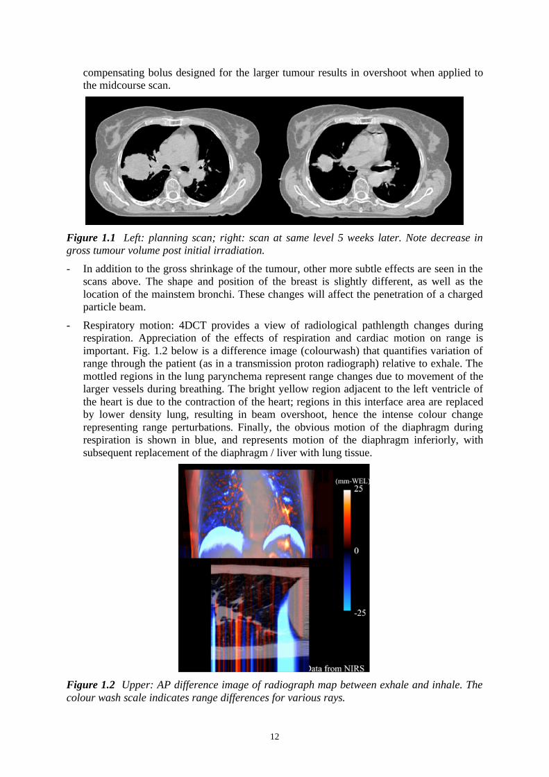
- Tumour shrinkage: Fig. 1.1 shows a treatment-planning scan acquired before initiation of
therapy. The CT scan on the right, at essentially the same anatomical level, shows
substantial (70cc) shrinkage of the tumour after 5 weeks of radiotherapy. Clearly a
1 Hanson K.M. et al, Phys. Med. Biol. 26 (1981) 965.
2 Sadrozinski H.et al. Nucl. Instr. and Meth. A511 (2003) 275.
3 Schulte R. et al, Med. Phys. 32 (2005) 1035.
4 Cirrone G. et al, Nucl. Instr. and Meth. A576 (2007) 194.
12
compensating bolus designed for the larger tumour results in overshoot when applied to
the midcourse scan.
Figure 1.1 Left: planning scan; right: scan at same level 5 weeks later. Note decrease in
gross tumour volume post initial irradiation.
- In addition to the gross shrinkage of the tumour, other more subtle effects are seen in the
scans above. The shape and position of the breast is slightly different, as well as the
location of the mainstem bronchi. These changes will affect the penetration of a charged
particle beam.
- Respiratory motion: 4DCT provides a view of radiological pathlength changes during
respiration. Appreciation of the effects of respiration and cardiac motion on range is
important. Fig. 1.2 below is a difference image (colourwash) that quantifies variation of
range through the patient (as in a transmission proton radiograph) relative to exhale. The
mottled regions in the lung parynchema represent range changes due to movement of the
larger vessels during breathing. The bright yellow region adjacent to the left ventricle of
the heart is due to the contraction of the heart; regions in this interface area are replaced
by lower density lung, resulting in beam overshoot, hence the intense colour change
representing range perturbations. Finally, the obvious motion of the diaphragm during
respiration is shown in blue, and represents motion of the diaphragm inferiorly, with
subsequent replacement of the diaphragm / liver with lung tissue.
Figure 1.2 Upper: AP difference image of radiograph map between exhale and inhale. The
colour wash scale indicates range differences for various rays.

13
- Trajectory changes: A tumour’s initial position and trajectory from day to day may
change. The MDAH has studied this using serial 4D CT, where a 4D scan is performed
once per week over the six weeks of radiotherapy. The results of such a study are shown
in Fig. 1.3.
Fig. 1.3 Each coloured curve represents the three-dimensional trajectory of a lung tumour
centre of mass from serial 4D CT scans performed on a weekly basis. The common
coordinate system is the vertebral column. The spine is aligned in each scan to the planning
scan (courtesy Lei Dong Mdah).
Note that on different serial CT scans, the initial position of the centre of mass of the tumour
is different, relative to bony anatomy. Furthermore, the trajectory varies in both amplitude
and position.
Setup in presence of variations of position, shape, and density changes is difficult; Physicians
are reluctant to use radio-opaque markers (clips) because of the risk of complications
(pneumothorax). Radio-opaque clips only show clip positions, not soft tissue changes in
anatomy; cone beam CT may help but only documents tumour position prior to treatment.
Cone-beam cannot be performed continuously during treatment. A Proton Range Telescope
can provide several important insights:
- Produce a radiograph that visualizes the location of the tumour on a daily basis;
- Produce a proton fluoroscopic video clip that documents tumour motion on a daily basis
and a minimal dose;
- Verify changes in tissue density or detect thickness changes in tissue thickness.
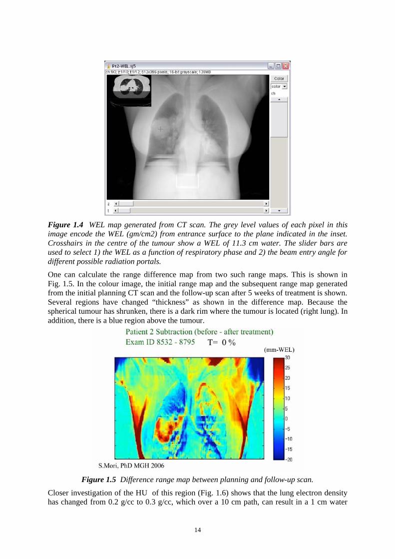
A range map can be generated from 4D CT data. At MGH tools have been developed, (S.
Mori, PhD) to calculate radiographic pathlength maps based on CT data. The Hounsfield
units of a CT scan are converted to relative stopping power. The image in Fig. 1.4 appears to
be a radiograph, but each element in the image is a measure of the water equivalent thickness
of the patient from anterior skin surface to a plane just anterior to the vertebral body (shown
in the picture within the picture). A large spherical tumour is seen in the right mid lung.
14
Figure 1.4 WEL map generated from CT scan. The grey level values of each pixel in this
image encode the WEL (gm/cm2) from entrance surface to the plane indicated in the inset.
Crosshairs in the centre of the tumour show a WEL of 11.3 cm water. The slider bars are
used to select 1) the WEL as a function of respiratory phase and 2) the beam entry angle for
different possible radiation portals.
One can calculate the range difference map from two such range maps. This is shown in
Fig. 1.5. In the colour image, the initial range map and the subsequent range map generated
from the initial planning CT scan and the follow-up scan after 5 weeks of treatment is shown.
Several regions have changed “thickness” as shown in the difference map. Because the
spherical tumour has shrunken, there is a dark rim where the tumour is located (right lung). In
addition, there is a blue region above the tumour.
Figure 1.5 Difference range map between planning and follow-up scan.
Closer investigation of the HU of this region (Fig. 1.6) shows that the lung electron density
has changed from 0.2 g/cc to 0.3 g/cc, which over a 10 cm path, can result in a 1 cm water

15
equivalent length radiological pathlength change. Because the typical lung density is 0.3 g/cc,
this leads to a geometric overshoot of approximately 3 cm of lung volume.
Figure 1.6 Sampling of HU of lung, documenting change in density of the ipsilateral lung
over time, while the HU of soft tissue, air, and contralateral lung remain stable.
The simulated coronal image below (Figure 1.7) shows the tumour in the right lung (posterior
view). A white circle indicates the ROI over which the MC calculation was performed. The
location and energy of each proton passing from the anterior skin surface was tracked
through the lung and chest wall, and into the plane just posterior to the back skin surface.
Approximately 1 million protons were used in the simulation.
Figure 1.7: Image of radiograph (proton) under calculation.
1.3 Proton Range Telescope
The Proton Range Telescope, PRT, chosen to apply the technique PRR, consists of a set of
position-sensitive detectors for tracking and a stack of plastic scintillator plates with
individual pulse height recording to determine the residual range of the particles after the
absorber (see Fig. 1.8). In view of their very high rate capability and excellent position
resolution, we have selected the Gas Electron Multiplier (GEM)5 as tracking detector; GEM1
5 Sauli F., Nucl. Instr. and Meth. A386 (1997) 531.

16
and GEM2 measure the incident proton trajectory, and GEM3 can be used optionally to reject
tracks with too large deviation from a straight line due to multiple scattering.
Figure 1.8: Schematics of the Proton Range Telescope
Detection of the last fired plate provides a rough measurement of the residual range; a fit of
the measured differential energy loss in each plate to the (known) Bragg curve should
provide, according the simulation (see below), an accuracy in the residual range comparable
to the measurement of the energy loss. To extend the range of energy covered, passive
absorbers can be inserted in front of the stack or in the gaps between scintillators.
1.4 Performance studies
Using a Monte Carlo code (Geant4) we have simulated various properties of the PRT.
Fig. 1.9 shows the integral energy loss profile as a function of penetration (Bragg curve) for
protons at two initial energies in plastic scintillator. The slow drop of the distribution at the
end is due to range straggling.
Figure 1.9 Energy loss profile (Bragg peak) for protons at 194 and 200 MeV in plastic
scintillator. The inset provides the corresponding average range.
This is shown also in Fig. 1.10 that provides, for three values of energy, the computed spread
in penetration, before the particle comes to stop, due to multiple scattering. As one can see, at
the highest energy the range straggling is 1% rms, corresponding to about 3 mm; this has
defined the initial choice of the scintillator thickness.

17
Figure 1.10 Range straggling of protons in plastic scintillator.
A thin segmentation of the range telescope and a simple digital count of the scintillators with
a pulse above a pre-determined threshold should allow reaching the quoted resolution.
However, recording the pulse height profile with a fit to the Bragg distribution can
substantially improve the residual range determination accuracy.
Fig. 1.11 shows the energy loss profile of a single proton track.
Figure 1.11 Single 200 MeV proton differential energy loss (in MeV/mm) computed for 3
mm thick samples.
The energy distributions towards the end of the range are shown in Fig. 1.12.
Figure 1.12 Differential energy loss spectrum for protons near the end of range
18
As seen in the figure, the energy loss resolution at the end of range, computed for one mm
scintillator, has a FWHM of about 20%, well below to the difference between two adjacent,
the energy loss resolution at the end of range, computed for one mm scintillator, has a
FWHM of about 20%, well below to the difference between two adjacent
Pending a more accurate simulation, it seems intuitive that a sampling of energy loss in a
number of adjacent slabs, even with moderate accuracy and taking into account straggling
and statistical dispersions should allow reconstructing the end point of the track with sub-mm
accuracy. The fit can be done taking the initial energy loss as normalization, resulting in a
moderate dependence of the result from a detailed calibration of response over the scintillator
area, assuming yield variations in different slabs to follow similar patterns.
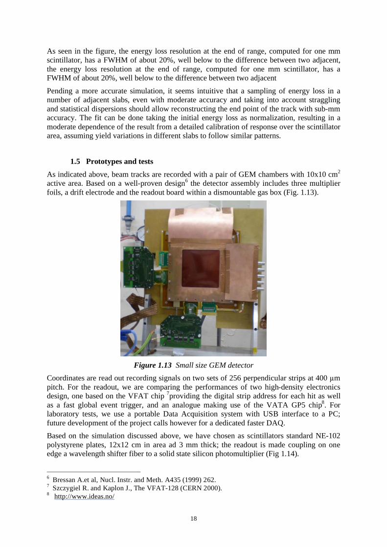
1.5 Prototypes and tests
As indicated above, beam tracks are recorded with a pair of GEM chambers with 10x10 cm2
active area. Based on a well-proven design6 the detector assembly includes three multiplier
foils, a drift electrode and the readout board within a dismountable gas box (Fig. 1.13).
Figure 1.13 Small size GEM detector
Coordinates are read out recording signals on two sets of 256 perpendicular strips at 400 m
pitch. For the readout, we are comparing the performances of two high-density electronics
design, one based on the VFAT chip 7providing the digital strip address for each hit as well
as a fast global event trigger, and an analogue making use of the VATA GP5 chip8. For
laboratory tests, we use a portable Data Acquisition system with USB interface to a PC;
future development of the project calls however for a dedicated faster DAQ.
Based on the simulation discussed above, we have chosen as scintillators standard NE-102
polystyrene plates, 12x12 cm in area ad 3 mm thick; the readout is made coupling on one
edge a wavelength shifter fiber to a solid state silicon photomultiplier (Fig 1.14).
6 Bressan A.et al, Nucl. Instr. and Meth. A435 (1999) 262.
7 Szczygiel R. and Kaplon J., The VFAT-128 (CERN 2000).
8 http://www.ideas.no/

19
Figure 1.14 Scintillator, WLS and SiPM
The scintillator and readout assembly are schematically shown in Fig. 1.15: a light support
plate, emptied in the active area, is used both to support the components of each module and
to assembly the modules. Depending on the thickness of the active components and
connectivity, the modules can be assembled coherently or rotated in pairs.
Figure 1.15 Schematics of a scintillator and sensor module.
For best performance, the WLS bar should be square in cross section, matching the size of
the SiPM; while 3x3 mm2 devices are expected to be available in the near future, we have
made preliminary tests using a smaller area sensor, the Hamamatsu Multi-Pixel Photon
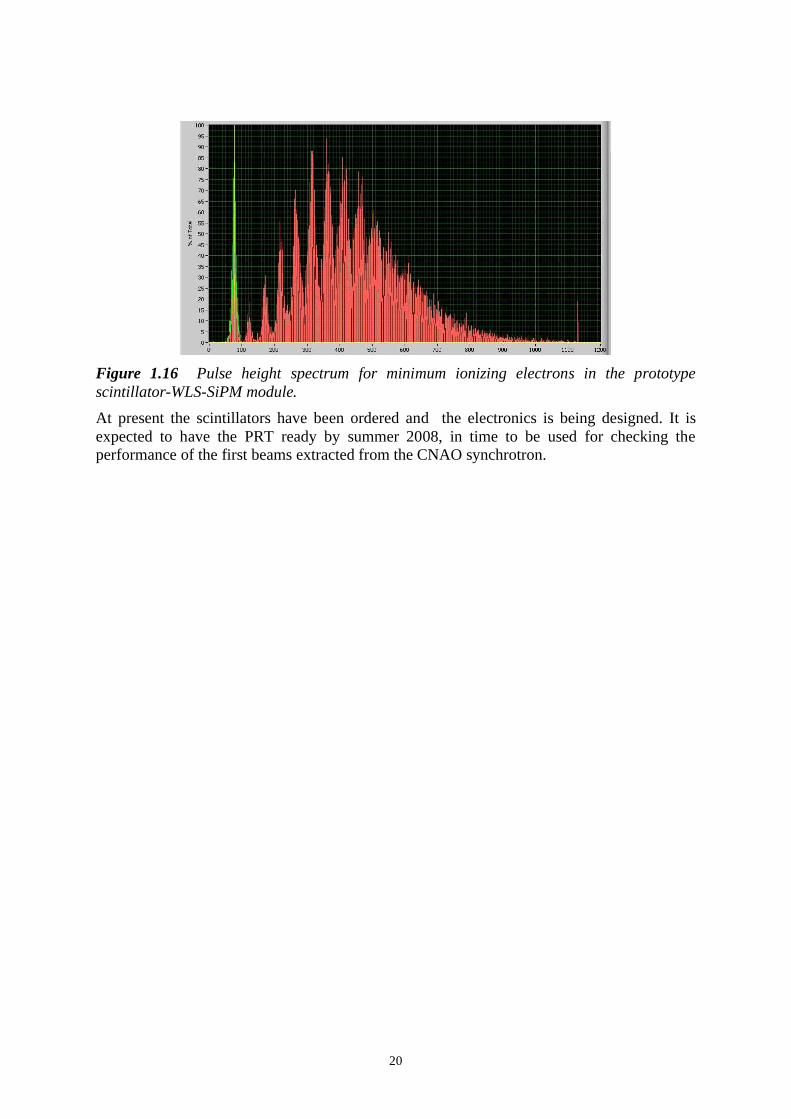
Counter (MPPC S10362) with 1 mm2 active area, and a 1 mm diameter WLS fiber. The pulse
height distribution recorded for minimum ionizing electrons from a 106
Ru source in
coincidence with a second scintillator is shown in Fig. 1.16; one can clearly distinguish the
single and multi-photoelectron peaks. The average value of the signal, about 8
photoelectrons, will increase by an order of magnitude when using a larger area sensor.
Moreover, protons of 200 MeV are already about four times above minimum ionizing, so we
expect a rather good resolution for each sample.
20
Figure 1.16 Pulse height spectrum for minimum ionizing electrons in the prototype
scintillator-WLS-SiPM module.
At present the scintillators have been ordered and the electronics is being designed. It is
expected to have the PRT ready by summer 2008, in time to be used for checking the
performance of the first beams extracted from the CNAO synchrotron.

21
2. VALIDATION OF THE GEANT4 CODE AND IN-BEAM-
PET CALCULATIONS
2.1 Introduction
Modern particle and nuclear physics experiments pose enormous challenges in the creation of
complex software frameworks and applications. Many codes have been developed in order to
satisfy the wide range of requirements of the physics community and hadrontherapy can of
course benefit of the progress made in this field. For the description of the interactions of
particles in matter many Monte Carlo tools have been developed and widely validated in the
high energy physics domain but a lack of information on the behaviour of these softwares at
the intermediate energies, of interest for hadrontherapy applications, still remains. Among
them, Geant4 9 10
has been selected for its flexibility in geometry and physics modelling.
In this Chapter, after a review of the interactions of hadrons beams in matter, the capabilities
of Geant4 to reproduce experimental data in the energy range of interest are discussed.
2.2 Interactions of charged hadrons in matter
Charged hadrons when passing through the matter release their energy mainly via interaction
with the electrons of the target material. Since the energy dissipated in each electronic
collision is very small, the energy loss of the projectile is practically continuous. The mean
energy loss (also called "stopping power" and "Unrestricted Linear Energy Transfer", LET) is
described by the Bethe-Bloch formula:
2 2 2
2 2
2 2
21 1
2 2
e maxeff
m c TdE ZKz ln
dx A I= , (2.1)
where:
• dE
dx is the energy loss [ 1 2MeVg cm ]
• is the ratio between the particle velocity and the velocity of light c
• effz is the effective charge of the incident particle
• A is the atomic mass of the medium [ 1g mol ]
• Z is the atomic number of the medium
• K A/ is equal to 2 24
A e eN r m c A/ whose value is 0.307075 1 2
MeVg cm
• I is the mean ionization potential of the atoms of the medium [eV ]
• max
T is the maximum kinetic energy transferred to a free electron in a single
collision
• is the density correction to the ionization energy loss.
Since the trajectory is practically straight, the range can be computed by integrating the
inverse of the stopping power from the initial energy of the projectile down to zero:
9 Agostinelli S. et al., "GEANT4-a simulation toolkit", Nucl. Instrum. Meth. A506 (2003) 250-303
10 GEANT4 Web page: http://geant4.cern.ch/

22
0
01( )
E
dER dE
dx= . (2.2)
At lower energies, some corrections to the Bethe-Bloch formula are required. The first one is
the shell correction, which takes into account the binding of the electrons in the target nuclei.
The Barkas effect, instead, explains why the energy loss of positive charged particles, e.g.
proton, is higher in respect to their antiparticle, e.g. p . This behaviour is due to the
polarization of target electrons toward (away) by positive (negative) projectile.
Another important effect occurring at low energies is the decreasing of the effective charge of
the projectile, effz , because when it slowly passes close to a target atom, it can collect some
of the electrons. This effect is described by the Barkas formula:
2 3125(1 )z
effz z e/
= , (2.3)
that underlines the dependence on the projectile velocity. Within the range of therapeutic
energies, the Bethe-Bloch formula is to a good approximation dominated by the effz term and
by 21 / . The latter determines the increase of the stopping power with decreasing projectile
energy.
The subscript in the symbol LET reminds the fact that in the atomic collisions all energy
losses are considered without restriction. In practice the subscription is forgotten and the
symbol used is simply LET. Plotted as a function of the residual range, the resulting curve is
the well known Bragg curve.
The LET values of light ions are summarized in Table 2.1 for particle energies corresponding
to the same range of 200 MeV protons, i.e. 262 mm.
Table 2.1. The energies in column 2 correspond to a range of 262 mm in water. The other
columns give the LET values at different depths in the target 11
..
LET [keV/ μ m] at various depth in water [mm] Charged
particle A
NZ
E MeV/u
R =262 mm
0 mm 112 192 232 261
1H
1+ 200.0 0.5 0.6 0.8 1.1 4.8
2He
2+ 202.0 1.8 2.2 3.1 4.4 20.0
7Li
3+ 243.3 3.7 4.6 6.2 8.9 40.0
11Be
5+ 329.5 8.5 10.0 13.5 19.0 87.5
12C
6+ 390.7 11.0 13.5 17.5 24.5 112.0
14N
7+ 430.5 14.5 17.5 22.5 31.5 142.0
16O
8+ 468.0 18.0 21.5 28.0 39.0 175.0
Since the energy loss is a stochastic process, a spread in energy always occurs after a mono-
energetic beam has passed through a given target thickness. The energy spread leads to the
range straggling, defined as the fluctuation in path length for individual particles of the same
initial energy. The range straggling, despite mainly dominated by the stochastic nature of the
energy loss, is also affected by the scattering experienced by the particles traversing a
11
Amaldi U. and Kraft G., "Radiotherapy with beams of carbon ions", Rep. Prog. Phys. 68 (2005)
1861-1882.

23
material. The range spread amounts to about 1% of the mean range of protons and it is only
0.3% for carbon ions, because of the dependence on the mass as 1 m/ .
Multiple scattering
A charged hadron passing through matter is deflected by several small angles in the
electromagnetic interactions with target nuclei. The Multiple Coulomb Scattering (MCS) can
be described at small angles by a Gaussian, according to the Molière theory, with a standard
deviation given by:
0
0
13 61 0 038
MeV xz x X ln
pc X
.= / + . , (2.4)
where x is the thickness of the material traversed, 0
X is the radiation length and p is the
particle momentum. At large depths the lateral definition of well collimated photon beams is
better than the one of protons.
Figure 2.1 Beam width at different depths in water of photons, protons and carbon ions
(courtesy of GSI).
Figure 2.1 shows also that carbon ion treatments are laterally more conformal than proton and
photon treatments.
Fragmentation processes
The biological effect in the target volume is reduced because only a fraction of the primary
particles reaches the end of the range without fragmentation and the fragments have, for the
same energy, lower biological efficacy.
The physical parameter capable to describe the attenuation of primary particles in the target is
the total reaction cross section R
, defined as the difference between the total and the elastic
cross sections. At high energies (higher than 20 MeV/u), R
is dominated by geometrical
factors, with an almost constant value. For the range region from the entrance point to a few
centimeters before the Bragg peak, the attenuation of the primary particles can be described
by the exponential law:
0( ) xN x N e= . (2.5)
The linear attenuation coefficient is related to R
by the equation:

24
24 1( ) (10 )
R t
A
barn AN
= , (2.6)
where t
A is the material molecular weight of the target and A
N is the Avogadro’s number.
A general model capable to describe fragmentation processes is the abrasion-ablation model 12
; a schematic representation is shown in Fig. 2.2
Figure 2.2 Schematic drawing of a peripheral collision as described by the abrasion-
ablation model 13
.
This model describes the more peripheral collisions. In fact, central and near central
collisions represent only 10% of all nuclear events.
The interactions result in a wide spread production of fragments. In peripheral collisions, the
target and the projectile overlap partially, depending on the impact parameter, and a fireball
is formed between overlapping nucleons (participants). Since the fireball is formed on time
scale of the order of 1023
s, the target and the projectile nuclei do not take part in the process
and for this reason are called “spectators”. The fireball has the same direction as the
projectile, but a lower energy per nucleon. The excited fireball, as well as the spectator
nuclei, de-excite by emitting nucleons (evaporation) until the energy drops under the nucleon
barrier potential. This last process can be up to 1016
s long. The fragments of the projectile,
resulting from peripheral collision, due to the dynamics of the interaction are mainly forward
directed; they can be isotopes of the spectator nuclei as well as lower Z ions.
Assuming that the reaction cross sections are energy independent, the build up of fragments
as a function of the depth x can be described by a homogeneous system of differential
equations of first order:
( ) ( )d
N x L N xdx
= , (2.7)
where ( )N x denotes the vector (1Z Z Z n
N N N, , ..., ..., ) and the element of the matrix L are
proportional to the partial charge-changing cross sections for the production of lower Z
fragments, while the elements of the diagonal of L are the total charge changing cross-
sections. The result is a linear combination of exponential functions 14
.
The final effect of the fragmentation process is a less sharp distal fall-off of the deposited
dose, with a long tail beyond the Bragg peak. This is due to the production of lower Z
fragments that, having the same velocity and thus energy per nucleon ofthe primary beam,
can travel more in the target because of the dependence of the range on 2
A Z/ . The
production of fragments increases with increasing the projectile A , the main parameter on
12
Oliveira L.F. et al., "Abrasion-ablation calculations of large fragment yields from relativistic heavy
ion reactions", Phys. Rev. C19 (1979) 826-833. 13
Crespo P., "Optimization of In-Beam Positron Emission Tomography for Monitoring Heavy Ion
Tumor Therapy", PhD thesis, Technischen Universitat Dresden, Germany (2005) 14
Schardt D. et al., "Nuclear Fragmentation of High-energy Heavy-Ion beams in water" Adv. Space
Res. 17 (1996) 287-204.
25
which R
depends. Carbon ions have been chosen at the beginning of the 90s as the best
compromise between (i) low/high LET in the entrance/final part of the range and (ii) limited
fragmentation with respect to lower/higher Z fragments. One of the advantages of nuclear
fragmentation is the production of positron emitting nuclei. These nuclei, as explained below,
allow the monitoring of primary particle range by means of a PET acquisition system.
2.3 Review of Monte Carlo codes available for medical applications
The Monte Carlo technique has become ubiquitous in medical physics in the last fifty years.
The range of applications is very broad: commercial treatment planning systems for external
beam radiotherapy, brachitherapy, dosimetry, diagnostic x-ray applications and
radioprotection are only some of the major examples. One of the most important tasks in
conventional radiotherapy, as well as light ion therapy, is the determination of the dose
distribution expected in patients. Monte Carlo techniques have always been understood to be
the most accurate way to perform this task, but the time required for the calculations was
considered as prohibitive. However, as computing power continues to decrease in cost while
increasing in speed, it becomes increasingly feasible to use Monte Carlo for treatment
planning.
Up to now, Monte Carlo applications in the medical field have involved mainly electron and
photon interaction and transport in matter. The most widely applied codes to conventional
radiotherapy are EGS (Electron Gamma Shower) 15
and PENELOPE (PEnetration and
Energy Loss Of Positrons and Electrons). In 2000 Kawrakow 16
introduced new significant
improvements to EGS which led to the development and release of the EGSnrc code. The
ensuing software package handled the most difficult of the simulation problems, namely the
calculation of the response of ion chambers. The PENELOPE package 17
contains a detailed
treatment of cross sections for low-energy transport and a flexible geometry package which
allows the simulation of accelerator transport lines. However these tools are not intended to
manage hadronic interactions.
Other tools have higher potentials for light ions therapy applications. FLUKA 18
is one of the
existing simulations of transport and interaction of particles in matter which is a complete
multipurpose tool. In fact, it can treat hadron-hadron, hadron-nucleus, neutrino,
electromagnetic and muon interactions up to 1000 TeV. It also manages interaction and
transport of neutrons down to thermal energies. With the increasing interest of applications to
dosimetry and therapy, a supporting software has been developed to allow the direct
conversion of the output files from standard CT-scans directly into a voxel geometry for
transport within FLUKA. In such a way the modelling of the human body is feasible. This
tool has been successfully used in 19
for the calculation of dose and positron emitters’
distributions in proton therapy. The reported agreement in range is 1 mm while the mean
agreement between Monte Carlo and treatment planning dose calculations is within 3%,
though local deviations up to 10% can occur. The accuracy of FLUKA to transport ion beam
15
Bielajew A. F. et al., "History, overview and recent improvements of EGS4" , Technical Report
PIRS-0436 (1994) 16
Kawrakow I., "Accurate condensed history Monte Carlo simulation of electron transport: EGSnrc,
the new EGS4 version", Med. Phys. 27 (2000) 485-498. 17
Baro J. et al., "PENELOPE: an algorithm for Monte Carlo simulation of the penetration and energy
loss of electrons and positrons in matter", Nucl. Instrum. Methods B100 (1995) 31-46 18
Fassò A. et al., "FLUKA: a multi-purpose transport code", CERN Yellow Report 2005-10 (2005) 19
Parodi K. et al., "Clinical CT-based calculations of dose and positron emitter distributions in
proton therapy using the FLUKA Monte Carlo code", Phys. Med. Biol. 52 (2007) 3369-3387.

26
in matter has been investigated in 20
, with an overall satisfactory agreement in both depth
dose distribution and fragmentation processes.
The MCNP (Monte Carlo N-Particle) system is a highly stable code tracking neutrons,
photons and electrons, by using evaluated data libraries for low-energy interaction
probabilities. It is maintained by a large group of scientists of the Los Alamos National
Laboratory. This code contains a very powerful geometry package, for example its lattice
geometry combined with the "fully specified fill" capability is of great relevance in dosimetry
applications. Thanks to the accurate modelling of neutron interactions, MCNP was widely
used for reactor simulation and neutron dosimetry, especially related to BNCT (Boron
Neutron Capture Therapy). In 1994 the development of the extended MCNP (MCNPX) was
started, with an extension to a comprehensive set of particles and light ions 21
.
Another multi-purpose particle and heavy ion transport Monte Carlo tool is PHITS (Particle
and Heavy Ion Transport code System) 22
. It is capable to simulate hadron-nucleus reactions
up to 200 GeV, nucleus-nucleus collisions from 10 MeV/u up to 100 GeV/u, transport heavy
ions and all hadrons including low energy neutrons down to 10-5
eV, as well as leptons. The
energy range of electrons and photons is restricted to 1 keV-1 GeV. Some new functionalities
have been added to improve the analysis of the dose distribution in carbon therapy systems.
The carbon ion depth-dose distribution shows a good agreement with experimental data, as
reported in 23
, where the carbon therapy aperture of the HIMAC beam line has been modeled
and simulated by means of PHITS.
A dedicated Monte Carlo code for the simulation of the transport of protons and heavier ions
in tissue-like media is SHIELD-HIT, a spin-off of SHIELD 24
. The original tool simulates the
interactions of hadrons and atomic nuclei with complex extended targets in an energy range
from 1 TeV/u down to 1 MeV/u, or to thermal energies in case of neutrons. Since the
developments of SHIELD-HIT (Heavy Ion Transport) were driven by applications to ion
radiation therapy, the most essential improvements refer to the inclusion of the fluctuations of
ionization energy losses and multiple Coulomb scattering of heavy charged particles. Energy
depositions up to and well beyond the Bragg Peak due to nuclear fragmentations are well
predicted 25
. Satisfactory agreement is also found with experimental determinations of the
number of fragments of a given type, as a function of depth in water, produced by 670 MeV/u 12
C and 14
N.
The Monte Carlo chosen for the present work is Geant4 (GEometry ANd Tracking) 26
27
, a
general purpose tool developed for particle physics applications. Geant4 has been used for
various applications in radiotherapy and it is the basis of the GATE simulation toolkit (see
later) for nuclear medicine applications in PET and SPECT.
20
Sommerer F.et al., "Investigating the accuracy of the FLUKA code for transport of therapeutic ion
beams in matter", Phys. Med. Biol. ,51 (2006) 4385-4398. 21
Waters L. S. et al., "The MCNPX Monte Carlo radiation transport code", AIP Conference
Proceeding 896 (2007) 81-90 22
Niita K. et al., "PHITS overview", AIP Conference Proceeding 896 (2007) 61-70 23
Nose H. et al., "Improvement of three-dimensional Monte Carlo code PHITS for heavy ion
therapy", J. Nucl. Sci. Tech.42 (2005) 250-255. 24
Dementyev A. V. et al., "SHIELD-universal Monte Carlo hadron transport code: scope and
applications", Rad. Meas. 30 (1999) 553-557. 25
Gudowska I.et al., "Ion beam transport in tissue-like media using the Monte Carlo code SHIELD-
HIT", Phys. Med. Biol. 49 (2004) 1933-1958. 26
GEANT4 Web page: http://geant4.cern.ch 27
Agostinelli S. et al., "GEANT4-a simulation toolkit", Nucl. Instr. and Meth. A 506 (2003) 250-303.

27
2.4 The Geant4 toolkit
Geant4 is driven by the software requirements of the high energy physics community. It’s an
object-oriented based software for particle transport; it is flexible thanks to its architecture,
implemented so that the description of the physics processes is visible. The user requirements
lead to a modular and hierarchical structure where sub-domains are linked by uni-directional
dependencies as shown in Fig. 2.3. The main domains (categories) of the simulation are:
• geometry and materials;
• particle interaction in matter;
• tracking management;
• digitization and hit management;
• event and track management;
• visualization;
• user interface.
Figure 2.3 The Geant4 toolkit modular diagram.

28
The user has the ability to create a geometry with a large number of components of different
shapes and materials, as well as to define sensitive components that record information (hits)
to simulate the detector response 28
. To model the behaviour of particles in matter a wide and
complete set of physics processes is implemented. In the flexible scheme of Geant4, the
management of these categories is performed by the track category, which contains classes
for tracks and steps (the Geant4 unit of length in the processing), used by processes, which
handle models of physical interactions.
One of the main processes is transportation, that controls the transport of particles in the
geometry model. The three main domains of physics processes are particle decay,
electromagnetic physics and hadronic physics. The class G4Decay implements a decay mode
according to branching ratios contained in the decay table for the particle. Geant4 provides
some default decay tables and models to determine the distribution of secondary particles. A
comprehensive description of the physics models implemented in Geant4 can be found in
Ref. 29
. In the next Section a detailed description of the physics chosen to simulate light ion
transport and interactions is given.
Physics models of the electromagnetic processes
In Geant4 many physics models, for electromagnetic and hadronic physics, are available.
Electromagnetic physics is divided in two categories: the standard and the Low Energy (LE)
physics. The development of the Low Energy (LE) package has been driven by the
requirements coming from medicine and space research.
Low energy physics for photons and electrons is available in two flavours: one based on the
Livermore Data Library and a second one based on the Penelope code, re-engineered in
Geant4. These packages provide a set of processes extending the coverage of the standard
electromagnetic physics down to 250 eV (Livermore) or to 100 eV (Penelope) for electrons
and photons. The Livermore LE physics is based on Data libraries from Loma Linda National
Laboratory that have been especially formatted for Geant4 distribution: EADL (Evaluated
Atomic Data Library), EPDL (Evaluated Photon Data Library) and EEDL (Evaluated
Electron Data Library). In principle the validity range of the libraries extends down to 10 eV,
but some unstable behaviour has been encountered. A detailed atomic modelling is described
in EADL for elements with 1 Z 100, and atomic relaxation is also included for atoms with
Z>5. In Ref. 30
the behaviour of LE electromagnetic physics was compared to the reference
data provided by NIST for different materials , focusing on:
• the total photon attenuation coefficients;
• the cross sections of the individual processes of photons;
• the stopping power and the range of electrons in the Continuous Slowing Down
Approximation (CSDA).
The Livermore LE model exhibits the best overall agreement with reference data with respect
to the standard electromagnetic physics, deviating less than 3% from the data.
These arguments led to the choice of the Livermore LE physics to be implemented in the
code used in the present study and the processes activated are:
28
"User’s guide", GEANT4 Web Page 29
"Physics Reference Manual", GEANT4 Web Page: http://geant4.cern.ch/ 30
Amako K. et al., "Comparison of GEANT4 Electromagnetic Physics Models Against the NIST
Reference Data", IEEE Trans. Nucl. Sci. 52 (2005) 250-303.

29
• : G4LowEnergyPhotoElectric, G4LowEnergyCompton,
G4LowEnergyGammaConversion and G4LowEnergyRayleigh;
• e- : G4MultipleScattering, G4LowEnergyIonisation and
G4LowEnergyBremsstrahlung;
• e+: G4MultipleScattering, G4eIonisation, G4eBremsstrahlung
and G4eplusAnnihilation.
Low energy processes are also available to model the electromagnetic interaction of hadrons
and ions. Different models are available, depending on the energy range, the particle type and
the charge and their validity extends down to approximately the ionization potential of the
interacting material. For energies larger than 2 MeV, the Bethe-Bloch formula is applied;
below 1 keV the free electron gas model is used. At intermediate energies various models are
available based on experimental data from Ziegler and on the ICRU reviews. Also in this
case, the Geant4 stopping power and range of protons and alfa particles in the CSDA
approximation have been compared to the NIST reference data, pointing out some
discrepancies between standard electromagnetic physics and reference data for low energy
alfa particles. Preliminary results 31
show an optimal agreement between the proton energy
deposition curve and the ICRU49 LE based simulation. On the basis of these results, the LE
electromagnetic physics with the ICRU49 parameterization has been adopted in the present
application.
In treating electromagnetic processes it is possible to apply cuts (in range and in energy) on
the production of secondaries. A range cut is converted, for each particle and for each
interacting material, in an energy cut. In this way, if the energy deposited in a step is lower
than this limit, the energy is supposed to be continuously deposited along the step instead of
being released to secondaries. The energy production cuts give the possibility to produce only
secondaries with energy larger than the indicated threshold. Depending on the purpose of the
simulation performed, the two values can be tuned in order to achieve a good balance
between the accuracy required (for example in Bragg curves computation) and the needed
computational time (since the higher the number of secondaries, the higher is the number of
particles to be tracked). For electromagnetic physics studies, the applied range cut is of
0.1 mm while the energy production cut has been set to 250 eV.
Physics models of the hadronic processes
The most critical part of the physics choice concerns hadronic processes. As already said,
many models are available but few have been tested with experimental data for the energy
range of interest in hadrontherapy (from few MeV up to few GeV).
The Bertini Cascade model has been selected to describe proton and neutron inelastic
interactions 32
. It is a classical cascade in nuclear medium: the target nucleus is modelled in
3-D and the incident particle is propagated in a density-dependent nuclear potential. The
interactions between the hadron and the nucleons are based on free-space cross sections.
Each secondary produced by an initial interaction is propagated in the nucleus until it
interacts again or leaves the nucleus. During the cascade exciton states are created and at the
end, by means of nuclear break up, in evaporation or fission processes, fragments are
produced. The validity range of the Bertini Cascade extends from 0 to 10 GeV. The Bertini
31
CHEP 2007 Web Page: www.chep2007.com 32
Heikkinen A and Stepanov N., "Bertini intra-nuclear cascade implementation in Geant4", CHEP
conference proceeding (2003).

30
cascade has been implemented in this work by using proton and neutron inelastic cross
sections provided by Geant4. The proton inelastic cross-section has been extrapolated from
Geant4 and compared to experimental data in Fig. 2.4 33
.
Figure 2.4 Proton inelastic reaction cross-section on 12
C target, as implemented in Geant4,
compared to experimental data.
The elastic interactions of neutrons is handled by the Low Energy neutron elastic model. Low
Energy models have also been used for capture and fission processes. Despite the validity of
these models extends down to 0 MeV, in the very low energy range (0-20 MeV) the Geant4
High Precision (HP) model has been chosen. HP makes use of a very accurate database
including both cross sections and final states.
In Geant4 for light ions (deuterons, tritons, 3H,
4H and generic ions) two models are available
to simulate inelastic interactions: the Wilson Abrasion-Ablation model and the Binary Light
Ion Cascade 34
. For this study, some preliminary investigations of the differences between the
two models have been carried out. They do not exhibit marked differences, as confirmed by
the proton and neutron production yield in a water target shown in Fig. 2.5.
Figure 2.5 Neutron (left panel) and proton (right panel) production yield for a 200 MeV/u
carbon ion beam interacting in a water target.
33
Bauhoff W., "Tables of reaction and total reaction cross sections for proton-nucleus scattering
below 1 GeV", Atomic Data and Nuclear Data Tables 35 (1986) 429-447. 34
"Physics Reference Manual", GEANT4 Web Page: http://geant4.cern.ch/

31
Since the Binary Cascade model is thought to describe better the underlying physics and
many other groups using Geant4 for medical applications have chosen it, it has been decided
to concentrate on this model for the rest of the work presented in this thesis. The Binary
Cascade modelling sequence is very similar to the Bertini Cascade, except that hadron-
nucleon interactions create resonances that decay according to their quantum numbers. The
model is valid for light ions with A 12, or higher if the target has A<12. The lower energy
limit of this model is 80 MeV but, since a model at very low energies for generic ions (so for
carbon ions too) is lacking, the validity has been forced down to zero energy.
The Binary Cascade needs to be completed with nucleus-nucleus total reaction cross sections.
Several models are available in Geant4 and in this study the Shen cross sections have been
selected; Fig. 2.6 shows the comparison of the 12
C-12
C reaction cross section with
experimental data 35
.
Figure 2.6 12
C-12
C reaction cross-section extrapolated from Geant4 are compared with
experimental data.
For deuteron, triton and alphas in the energy range between 0 and 100 MeV, the Low Energy
Parameterized (LEP) models have been implemented. They are based on fits of data and
theoretical models, and are faster than cascade models even if less accurate. For + and
- the
LEP model has also been used. The Low Energy Elastic scattering model has been applied to
all particles (except neutrons). This is a classical scattering description, based on
parameterizations of the cross sections and angular distributions. It can be in principle used
for all long-lived hadrons at all energies.
The decay of radioactive nuclei is simulated in Geant4 by means of data driven models. The
decays implemented are , +,
- and Electron Capture (EC). Data are derived from Evaluated
Nuclear Structure Data File (ENSDF) where half-lives, nuclear level structure for the parent
and daughter nuclide, branching ratios and energy of the decay process are reported. If the
daughter of a nuclear decay is an excited isomer, its prompt nuclear de-excitation is treated
by the G4PhotonEvaporation model.
All simulations of this study were performed by means of the release 8.2 of Geant4.
35
Shen W. et al., "Total reaction cross section for heavy ion collisions and its relation to the neutron
excess degree of freedom.", Nucl. Phys. A 491 (1989) 130-146.

32
2.5 Physics validation of the electromagnetic processes
In hadrontherapy applications, the first requirement for a Monte Carlo code is to reproduce
with sub-millimetric precision the range of light ions in tissue equivalent material. The Bragg
curve is mainly dominated by electromagnetic interactions, but the higher the energy and the
Z of the projectile, the larger is the contribution to the dose by secondary fragments, both in
the peak region and in the distal fragmentation "tail". In order to reproduce with high
accuracy the Bragg curves of carbon ions, it is possible to operate a fine tuning by changing
the value of the ionization potential (symbol W) of the target material. This approach is
reasonable since it has been recently pointed out 36
that the mean ionization potential of water
has a certain degree of uncertainty.
The simulation set-up consisted of a 30 cm water phantom divided in 100 m thick slices,
such a small thickness being chosen in order to locate the peak with high accuracy. The
energy deposited by the primary mono-energetic pencil-like beam in the phantom was
collected in each slice. The simulated curves were compared to experimental data acquired at
GSI in water by means of an ionization chamber 37
at four primary beam energies: 100, 200,
300 and 400 MeV/u.
In order to find the optimal ionization potential of water, the difference between the
experimental peak position and the simulated one at a certain energy was computed for
different values of W: 72, 74, 76 and 78 eV.
Fig. 2.7 shows the behaviour of range difference when the W value is varied.
Figure 2.7 Range difference between experimental and simulated Bragg curves of
12C ions
of 100 (filled circle), 200 (filled square), 300 (open circle) and 400 (filled triangle) MeV/u.
The best agreement with the experimental data is obtained for a potential W =74 eV.
Note that the difference is less pronounced at low energies: at both 100 MeV/u and 200
MeV/u the computation agrees with the data better than 0.5 mm for all W values. The
disagreement increases at higher beam energies. At 400 MeV/u energy, with W= 78 eV, the
measured and computed ranges differ by 1.6 mm.
A more detailed insight in the dependence of Bragg curves on ionization potential is given by
Fig. 2.8. It is seen that, with the choice W=74 eV, the measured and computed peak values
agree within -6%and +15%.
36
Helmut P., "The mean ionization potential of water, and its connection to the range of energetic
carbon ions in water", Nucl. Instr. and Meth. B 255 (2007) 435-437. 37
Bourhaleb F., personal communication.

33
Figure 2.8 Comparison of simulated Bragg curves with experimental data for different
ionization potential.
To further assess the correctness of the chosen W value, and not only by means of an integral
estimator (i.e. the maximum of the Bragg curve), the single track range distribution was
calculated for different values of the ionization potential. The positions where the carbon ions
came to rest was fitted by means of a Gaussian and the mean value was assumed as the range
at a given W value and primary energy. Fig. 2.9 shows the distributions at 400 MeV/u carbon
ions.
Figure 2.9 Distributions of the single track range in water of 400 MeV/u carbon ions at
different W values.

34
The difference between the calculated differential ranges and the experimental ones are
presented in Fig. 2.10. It is seen that the difference increases with increasing ionization
potential. The optimal value is W=72 eV.
Figure 2.10 Difference of the single track range with respect to the maxima of the
experimental Bragg curves.
The result slightly differs from the one previously obtained but since it refers to the
comparison between the calculated differential and the experimental integral ranges, some
deviations are acceptable. The difference with W=74 eV is less than 1 mm, so that this was
kept as the optimum value of the ionization potential.
The overall agreement with experimental data is shown in Fig. 2.11. All the Bragg curves
have been normalized to the energy deposited in the first slice, in order to have a common
point.
Figure 2.11 Comparison of simulated carbon ion Bragg curves with experimental data at
different energies in water.
The agreement with experimental data is satisfactory in the entrance part of the curve, but at
higher energies, when the fragmentation processes become increasingly relevant, the energy
deposited in the tail is underestimated. The underestimation can be due either to an incorrect
energy deposition by secondary fragments or to a lower fragment production yield. This point
will be further investigated in the next Section.
Polymethyl methacrylate (PMMA, = 1.18 g/cm) is a material that will be used in the next
Sections for hadronic physics validation. Since it is important to verify the correctness of the

35
coded electromagnetic processes in this medium, the Bragg curve was simulated and
compared to the data published in Ref. 38
. In the experiment the primary carbon ion was
279.23 MeV/u. The value of the ionization potential used in the simulation is 68.5 eV, the
Geant4 default value.
Since the calculation is performed in PMMA while the experimental data are given in water
equivalent depth, a rescaling factor was applied to the curve. By taking the values at different
carbon ion energies of the Stopping Power (SP) in liquid water and PMMA from ICRU73 39
,
the ratio of the two SPs has been computed. For a wide interval of energies, down to few
MeV, the ratio is nearly constant with an average value of 0.97. Considering the densities of
water and PMMA, it comes out that 1 mm of Water is equivalent to 1.14 mm of PMMA
which means that the same dose is deposited in 1.14 mm of water or in 1 mm of PMMA. As
shown in Fig. 2.12, the agreement is good.
Figure 2.12 Top panel: comparison of simulated Bragg curve with experimental data in
PMMA for a 279.23 MeV/u carbon ion energy. Bottom panel: contribution to the dose due to
secondary fragments.
In the bottom panel of the same figure, the contribution of the secondary fragments to the
energy deposited is shown. The larger contribution to the dose, in the region before the Bragg
peak, is given by Z=5 fragments. In the distal region instead, the larger contribution is due to
Z =1 and Z =2 fragments.
38
Matsufuji N. et al., "Influence of fragment reaction of relativistic heavy charged particles on
heavy-ion radiotherapy", Phys. Med. Biol 48 (2003) 1605-1623. 39
"Stopping of Ions Heavier that Helium", Journal of the ICRU Report 73 5 (2005)
36
2.6 Physics validation of the hadronic processes
The production of projectile nuclear fragments is a most important but not yet well
understood problem in the use of light ions for radiotherapy since the fragments - produced
inside the patient body - reach a region beyond the range of the primary particles.
To compute their effect one has to take into account that the biological effectiveness of
charged particles depends on the particle specie.
The fragment fluence, energy and LET distributions of each particle species, are often
globally called "beam quality". The knowledge of the beam quality as a function of the depth
is necessary for the precise estimation of the clinical effects of any therapeutic beam.
Unfortunately hadronic interactions cannot be accurately simulated, because of the scarcity of
good experimental data, and a model of high predictive capability has to be used.
The validation presented in the following is based on measurements performed at the GSI
facility by E. Haettner 40
and by K. G. Marx 41
Both experiments were realized at the heavy
ion synchrotron SIS18, accelerating 12
C ions between 80 MeV/u and 430 MeV/u. This energy
interval corresponds to water ranges 2 - 30 cm.
In the study performed by E. Haettner, nuclear reactions have been studied in a water
phantom with adjustable water thickness. The target was a 60x50x50 cm3 box, with 2 mm
thick plexiglass windows at the entrance and at the exit of the beam. A 5 cm diameter air
filled tube entered the target and could be moved back and forth, so that the water thickness
could be adjusted. A step motor controlled the movements of the tube with high precision and
reproduced positions with an accuracy of 8 m. The number of incoming ions that hit the
target were counted by means of a 1.5 mm thin plastic scintillator. The signal from this
detector was also used to start the time-of-flight measurements and, for this reason, it was
also called "Start detector". The detector area was 10x10 cm2 and was always positioned in
front of the target, few cm from the beam exit window.
In order to recognize the fragments exiting the target two approaches were applied.
The first technique was based on a thin scintillator used in dual mode: to measure the energy
loss E of the particle and the time-of-flight. The E of a particle of charge Z and speed v is
given by
2 2E Z v/ , (2.8)
while the time-of-flight t is related to the kinetic energy of the particle as follows
2
02
1
1 ( )kin
l
t c
E m c= , (2.9)
where l is the distance travelled by the particle.
The second technique employed two detectors: a thin detector to measure the energy loss E
and a thicker detector, capable of stopping all the particles, to obtain the total energy E. The
typical outputs of the two different measurements are shown in Fig. 2.13.
Even if the apparatus was intended to measure carbon ions, the telescope was capable of
detecting secondary boron nuclei as well.
40
Haettner E., "Experimental study on carbon ion fragmentation in water using GSI therapy beams",
Master thesis, Kungliga tekniska hogskolan, Sweden (2006) 41
Gunzert Marx K., "Nachweis leichter Fragmente aus Schwerionenreaktionen mit einem BaF2
Teleskop-Detektor", PhD thesis Darmstadt University of Technology, Germany (2004)
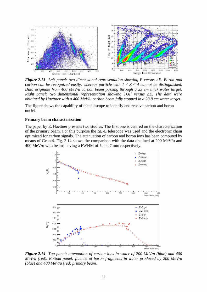
37
Figure 2.13 Left panel: two dimensional representation showing E versus E. Boron and
carbon can be recognized easily, whereas particle with 1 Z 4 cannot be distinguished.
Data originate from 400 MeV/u carbon beam passing through a 23 cm thick water target.
Right panel: two dimensional representation showing TOF versus E. The data were
obtained by Haettner with a 400 MeV/u carbon beam fully stopped in a 28.8 cm water target.
The figure shows the capability of the telescope to identify and resolve carbon and boron
nuclei.
Primary beam characterization
The paper by E. Haettner presents two studies. The first one is centred on the characterization
of the primary beam. For this purpose the E-E telescope was used and the electronic chain
optimized for carbon signals. The attenuation of carbon and boron ions has been computed by
means of Geant4. Fig. 2.14 shows the comparison with the data obtained at 200 MeV/u and
400 MeV/u with beams having a FWHM of 5 and 7 mm respectively.
Figure 2.14 Top panel: attenuation of carbon ions in water of 200 MeV/u (blue) and 400
MeV/u (red). Bottom panel: fluence of boron fragments in water produced by 200 MeV/u
(blue) and 400 MeV/u (red) primary beam.

38
To obtain the Geant4 points (indicated as g4 in the figure) the experimental set-up has been
reproduced in the simulation. The 40 cm water phantom was divided into 8 mm thick layers
and the ion fluxes were recorded at each layer interface, saving the properties of each
fragment: A, Z, energy, position and momentum.
The attenuation of carbon ions is well described by an exponential, up to few centimetres
before the Bragg peak, where the number of ions drops rapidly. The value of the attenuation
length computed at 400 MeV/u from the simulation is 257 mm, to be compared to the value
259±5 mm reported by E. Haettner. Overall, both the simulated carbon and boron fluences
are in excellent agreement with the experimental data.
Another interesting property is the evolution of the lateral distribution of carbon nuclei after
traversing various water thicknesses. Experimentally, the lateral distribution of the particles
was measured by means of a MWPC. From the simulation point of view, since the position of
each ion is recorded at each slice interface, a Gaussian fit has been applied and the FWHM of
the lateral distribution computed. The results of the calculation are compared with the
experimental data in Fig. 2.15 for the same 200 and 400 MeV/u primary beams.
Figure 2.15 FWHM of the transverse distribution of carbon nuclei at different water depths
for 200 MeV/u (blue point) and 400 MeV/u (red point) primary beams.
The distribution of carbon ions for the 200 MeV/u beam is in the error bars of the data
acquired at GSI. At the higher energy the FWHM of the carbon beam is underestimated by
Geant4. This happens in the last 10 cm before the Bragg peak, probably because the small
angle approximation of the Monte Carlo simulation fails.
Fragment fluences and spatial distributions
The second study by E. Haettner aims to investigate the build up of fragments of different Z
due to the interaction of 400 MeV/u carbon ions in water, whose range is 27 cm. Particles
were identified with the time-of-flight technique. The angular spectra of the fragments were
acquired at different angular positions between 0 and 10 degrees, with respect to the primary
beam direction, and for seven depths of the water target, ranging between 5.9 and 34.7 cm.
The angular distribution of each fragment was fitted with the equation:
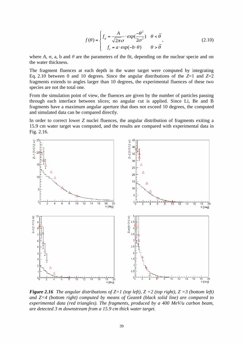
39
2
2( )
( ) 22
( )
g
e
Af exp
f
f a exp b
= <= ,
= >
(2.10)
where A, , a, b and are the parameters of the fit, depending on the nuclear specie and on
the water thickness.
The fragment fluences at each depth in the water target were computed by integrating
Eq. 2.10 between 0 and 10 degrees. Since the angular distributions of the Z=1 and Z=2
fragments extends to angles larger than 10 degrees, the experimental fluences of these two
species are not the total one.
From the simulation point of view, the fluences are given by the number of particles passing
through each interface between slices; no angular cut is applied. Since Li, Be and B
fragments have a maximum angular aperture that does not exceed 10 degrees, the computed
and simulated data can be compared directly.
In order to correct lower Z nuclei fluences, the angular distribution of fragments exiting a
15.9 cm water target was computed, and the results are compared with experimental data in
Fig. 2.16.
Figure 2.16 The angular distributions of Z=1 (top left), Z =2 (top right), Z =3 (bottom left)
and Z=4 (bottom right) computed by means of Geant4 (black solid line) are compared to
experimental data (red triangles). The fragments, produced by a 400 MeV/u carbon beam,
are detected 3 m downstream from a 15.9 cm thick water target.
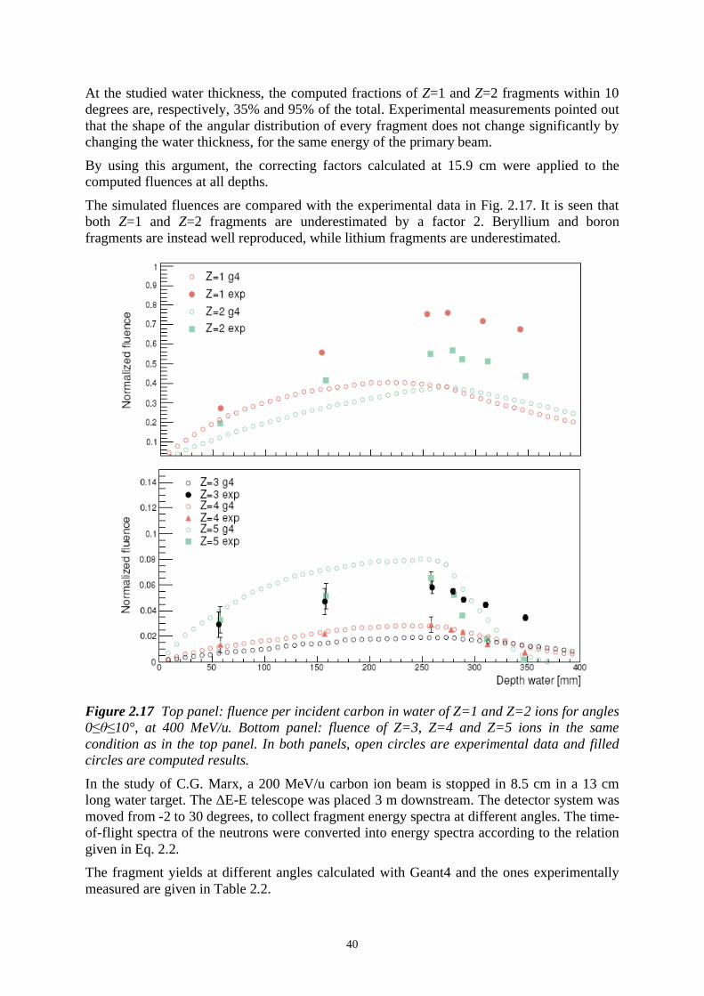
40
At the studied water thickness, the computed fractions of Z=1 and Z=2 fragments within 10
degrees are, respectively, 35% and 95% of the total. Experimental measurements pointed out
that the shape of the angular distribution of every fragment does not change significantly by
changing the water thickness, for the same energy of the primary beam.
By using this argument, the correcting factors calculated at 15.9 cm were applied to the
computed fluences at all depths.
The simulated fluences are compared with the experimental data in Fig. 2.17. It is seen that
both Z=1 and Z=2 fragments are underestimated by a factor 2. Beryllium and boron
fragments are instead well reproduced, while lithium fragments are underestimated.
Figure 2.17 Top panel: fluence per incident carbon in water of Z=1 and Z=2 ions for angles
0 10°, at 400 MeV/u. Bottom panel: fluence of Z=3, Z=4 and Z=5 ions in the same
condition as in the top panel. In both panels, open circles are experimental data and filled
circles are computed results.
In the study of C.G. Marx, a 200 MeV/u carbon ion beam is stopped in 8.5 cm in a 13 cm
long water target. The E-E telescope was placed 3 m downstream. The detector system was
moved from -2 to 30 degrees, to collect fragment energy spectra at different angles. The time-
of-flight spectra of the neutrons were converted into energy spectra according to the relation
given in Eq. 2.2.
The fragment yields at different angles calculated with Geant4 and the ones experimentally
measured are given in Table 2.2.

41
Table 2.2 Fragment yields in various angular angular ranges with respect to the beam
direction for a 200 MeV/u carbon beam fully stopped in 13 cm water.
0 10 degrees 0 20 degrees
Fragment G4 exp. G4 exp.
n 0.098 0.109± 0.022 0.255 0.243± 0.049
p 0.070 0.076± 0.011 0.154 0.147± 0.022
d 0.024 0.038± 0.006 0.041 0.068± 0.010
t 0.008 0.016± 0.002 0.014 0.026± 0.004
3He 0.008 0.028± 0.004 0.013 0.032± 0.005
4He 0.075 0.086± 0.013 0.107 0.092± 0.014
0 45 degrees 0 90 degrees
Fragment G4 exp. G4 exp.
n 0.534 0.462± 0.092 0.751 0.541± 0.108
p 0.229 0.194± 0.029 0.256 0.198± 0.030
d 0.046 0.081± 0.012 0.046 0.082± 0.012
t 0.016 0.029± 0.004 0.016 0.029± 0.004
3He 0.014 0.032± 0.004 0.014 0.032± 0.004
4He 0.108 0.093± 0.014 0.108 0.093± 0.014
The yields of neutrons, protons and alfa particles are in good agreement with the
experimental data over a wide angular range. In the simulated total production yield
deuterons, tritons and He-3 fragments are underestimated by about a factor 2.
In Table 2.3 the Geant4 and the experimental results are compared with simulation results
obtained by means of the FLUKA code 42
.
Table 2.3 Fragment yield fin the angular range 0 10° for a 200 MeV/u carbon beam.
Fragment G4 FLUKA exp.
p 0.070 0.088 0.076± 0.011
d 0.024 0.039 0.038± 0.006
t 0.008 0.023 0.016± 0.002
3He 0.008 0.016 0.028± 0.004
4He 0.075 0.143 0.086± 0.013
FLUKA exhibits, compared to Geant4, an opposite trend since it overestimates all fragments,
in particular alfa particles.
The energy spectra of neutrons, protons and alphas are compared to the experimental data in
Figs. 2.18 and 2.19.
42
Sommerer F.et al., "Investigating the accuracy of the FLUKA code for transport of therapeutic ion
beams in matter", Phys. Med. Biol. 51 (2006) 4385-4398.

42
Figure 2.18 Neutron energy spectra at 0, 5, 10, 20 and 30 degrees. Spectra are cut below 20
MeV because of the high inefficiency of the detector (data: bars; simulation: crosses).
Figure 2.19 Energy spectra of protons (left) and alfas (right) at 0° (data: red circles,
simulation: red bars), at 10° (data: green squares, simulation: green bars) and at 30 (data:
blue triangles, simulation: blue bars).
The overall agreement is reasonable. Some deviations from measurements emerge for the
fragments of Fig. 2.19 in the low energy part of the spectra, while the high energy
components of the proton and neutron spectra are well reproduced.

43
The 0 degrees spectra are peaked around 130 MeV/u and the peaks move towards lower
energies with increasing angular aperture. Neutron and proton spectra are rather wide. If we
consider the abrasion-ablation model described in Section 2.2 as reference model, the energy
distribution can be better understood.
The projectile nucleus, after the interaction with a target nucleus, can be left in an excited
state. Therefore it de-excites emitting nucleons, with energy much higher than the mean
primary beam energy per nucleon, also because of the Fermi momentum. These nucleons
contribute to the high energy part of the spectrum. At intermediate energies, the spectrum is
dominated by nucleons produced by the fireball break-up. Instead, the low energy component
is mainly due to nucleons emitted by excited target nuclei. Heavier fragments, like deuteron,
triton and alphas, come uniquely from the break-up of the fireball into small complexes.
2.7 Positron-emitters distribution in tissue-like media
In preparation of the work to be done for the definition of the in-beam-PET detector, this last
Section is devoted to the comparison with experimental data of the yields of positron emitting
nuclei computed with Geant4.
Among all fragments produced by carbon ion interactions, positron emitters are also
produced. Since the initial energy per nucleon is the same and the momenta are nearly
parallel, a clear correlation exists between the ranges of the primary ions and of the projectile + -emitter fragments. This correlation is the key point on which in-beam PET is based. The
present study aims to test the capability of Geant4 to correctly reproduce the production
yields and the spatial distribution of positron emitters produced by carbon ions. The
experimental data used are taken from the very complete study reported in 43
.
The measurements have been realized at GSI. Incident primary beams of different energies
are considered. The target was made of PMMA instead of water, since the stochiometry
(C5O
2H
8) is much closer to that of human tissue due to the presence of carbon. The target
dimensions were 300 90 90 cm3 box. The positron emitting nuclei considered in this study
were 11
C, 10
C and 15
O. The first two species are produced by projectile as well as by target
fragmentations.15
O is instead only due to target nuclei break-up. Other positron emitters like 12
N and 8B have lower production yields and shorter time-lives and tare not considered here.
In the experiment the targets were irradiated for an average time of 10 minutes. The activity
induced was measured for 10-20 minutes after stopping the irradiation by means of the in-
beam PET detector present at the GSI irradiation site. The relative amount of the isotope l ,
Nl, present at the end of the irradiation, was deduced by means of a fit of the activity
measured for several minutes after the end of the irradiation. Since only monoenergetic
beams have been used, the isotope production rate in each beam was supposed to be constant.
Therefore it is possible to use a recursive formula to extrapolate the production rate of the
isotope of interest, with the condition that the final amount at the end of the beam extraction
must be equal to Nl.
The measurements were repeated for several primary beam energies. In order to extrapolate
an absolute isotope production rate, the measured activity must be corrected for the
geometrical efficiency of the scanner and the gamma attenuation in the target. From the
43
Parodi K., "On the feasibility of dose quantificaion with in-beam PET data in radiotherapy with 12
C and proton beams", PhD thesis,Technischen Universitat Dresden, Germany (2004)

44
simulation point of view, + -emitters have been identified and registered in the position
where they decay.
In Tab. 2.4 the comparison of the calculated isotope yields with the experimental data is
reported. Data for the energy of 337.50 MeV/u are taken from 44
..
Table 2.4 Positron-emitter yields produced in PMMA for different carbon ion energies.
Energy 12
C
[MeV/u]
N 11C
/N0
[% ]
N 15O
/N0
[% ]
N 10C
/N0
[% ]
G4 exp. G4 exp. G4 exp.
212.12 10.2 10.5± 1.0 2.1 2.1± 0.2 1.9 0.8± 0.3
259.50 14.3 14.6± 1.5 3.1 3.1± 0.3 2.5 1.1± 0.2
337.50 18.9 22.0± 2.2 5.2 5.0± 0.5 3.4 1.6± 0.2
343.46 19.4 19.9± 2.0 5.4 5.1± 0.3 3.6 1.5± 0.3
The agreement with experimental data is very good for 11
C and 15
O yields. Instead, the few 10
C nuclei are overestimated by Geant4 by a factor two. The computed results for 259.5
MeV/u are compared in Tab. 2.5 with the production rates computed by the POSGEN code45
.
Table 2.5 Comparison between the Geant4 and the POSGEN + -emitter yields in PMMA .
Source Energy
[MeV/u] N 11
C/N
0
[% ]
N 15O
/N0
[% ]
N 10C
/N0
[% ]
Data 259.50 14.6± 1.5 3.1± 0.3 1.1± 0.2
Geant4 259.50 14.3 3.1 2.5
POSGEN 270.55 26.7 10.0 2.0
For the lowest and the highest energies, the spatial distribution of + -emitters is shown in
Fig. 2.20. It is seen that 11
C isotopes have a distribution characterized by a pronounced peak,
since they are mainly produced by projectile fragmentations. In the same picture, the
distribution of the annihilation points of e+ is also shown: due to the low positron end-point
energy of the considered isotopes, the mean path is rather low and the correlation to the real
isotope distribution is very good. In the distal part of the Bragg peak, the long tail is made of
isotopes mainly produced by proton induced fragmentation. 11
C has the same Z of carbon
ions, but a lower A leading to a shorter range. But since the mass is lower, it experiences a
higher multiple scattering, with a resulting broader spatial distribution, as shown in the
bottom panel of the figure.
44
Fiedler F. et al., "The Feasibility of In-Beam PET for Therapeutic Beams of 3He", IEEE Trans.
Nucl. Sci. 53 (2006) 2252-2259. 45
Ponisch F. et al., "The modelling of positron emitter production and PET imaging during carbon
ion therapy", Phys. Med. Biol. 49 (2004) 5217-5232.

45
Figure 2.20 Top panel: depth isotope distribution from 212.12 MeV/u (left) and 343.46
MeV/u (right) 12
C. Bottom panel: 2-D spatial distribution of all isotopes produced by 212.12
MeV/u (left) and 343.46 MeV/u (right) 12
C.
The computed isotope distribution has been compared to experimental data reported by
Ponisch F. et al.
The primary beam energy was 337.5 MeV/u and the target material was PMMA. Only
coincidences coming from a well defined region of the target (slices of 5 mm each) have been
acquired and, for each acquisition, the activity has been recorded at different times in short
time window. The evolution of the activity with time should carry out information
concerning the different radioisotope concentrations, since each one contributes inversely
with respect to its time-life. Every isotope distribution has been normalized to the total
number of isotopes produced (experimentally and computationally).
The result are given in Fig. 2.21. The agreement is excellent for 11
C and rather good for 15
O. 10
C is, as expected, overestimated. It can be seen that few centimeters before the Bragg peak
region, 10
C distribution has a quite pronounced peak. This could signify that the high
production rate of 10
C is due to the too high projectile fragmentation in Geant4.

46
Figure 2.21 Relative abundance of isotopes as a function of the depth in PMMA produced by
a 337.5 MeV/u carbon beam.
2.8 Discussion of the results
The Geant4 capability to reproduce the interactions of carbon ions in tissue equivalent
material was tested with respect to both electromagnetic and hadronic physics.
Concerning electromagnetic physics, the Bragg curves in water and PMMA phantoms for
different primary beam energies have been compared to experimental data. In order to
achieve a sub-millimetric agreement with respect to the localization of the peak, a fine tuning
of the ionization potential value of water has been operated. The optimum value is 74 eV,
with which the entrance part and the peak position are correctly calculated.
At higher energies, when nuclear reactions play an important role, the energy released in the
distal part of the curve is underestimated. This can be due to the low production yield of
secondary fragments as well as to the incorrect energy deposited by lower Z fragments
(mainly Z =1 and Z =2). This last hypothesis is less probable since the Low Energy
Ionization model based on ICRU49 was chosen because of the good agreement with
experimental data, with respect to protons and alphas, reported in several works. It has to be
underlined that the calculated optimum value of the ionization potential (W =74 eV) reported
in the present study has to be considered as relative. In fact, an improvement of the secondary
fragment production and therefore of the energy deposited would require a new estimation of
the W value.
Carbon ions attenuation in water is instead very well reproduced by the code and a mean
value of the attenuation length =257 mm is obtained, to be compared to the experimental
value =259 ± 5 mm. Also the build up of boron fragments is in good agreement with
experimental data .
While Z 4 fragments are well reproduced, the production yields of Z =1 and Z =2
fragments are underestimated by 50% and 30% respectively (Fig. 30) at 400 MeV/u carbon
beam, whereas at 200 MeV/u the production yields of protons and alphas are in good
agreement with measurements. Therefore with increasing the energy of the projectile the
discrepancies are more pronounced, suggesting that some charge-changing cross sections are
underestimated leading to an effect that increases with increasing the range and hence with
the energy.

47
Since the attenuation of the primary carbon ions agrees with data and hence its total charge
changing cross section, one can suppose that the low production yield can be due to an
underestimation of the reactions induced by secondary fragments. This hypothesis needs
further investigation and direct comparison with experimental data.
In the last release of Geant4 (9.0) new nucleon-nucleus reaction cross sections have been
implemented, based on experimental data. A comparison was performed between the results
obtained with the previous release (8.2) and the new one (9.0). Fig. 2.22 shows the
comparison of the Z =1 and Z =2 fluences calculated by means of the last Geant4 release and
the measured ones.
Figure 2.22 Comparison of the fluences of Z =1 and Z =2 fragments originated by 400
MeV/u carbon beam in 30 cm thick water target obtained experimentally and by means of the
new release 9.0 of Geant4.
An increase of the Z =1 production yield has been obtained, with a 30% difference between
calculated and experimental fluences to be compared to the 50% value obtained by the
previous release.
The capability of Geant4 to correctly simulate the production of positron emitters and their
distribution in tissue equivalent material has been also investigated. The isotopes analyzed
are 11
C, 10
C and 15
O and a good agreement with experimental data was obtained leading to
the conclusion that neutron emission is correctly reproduced by the code.
The overall agreement of the Geant4 based code described in the present Chapter is not
completely satisfactory, at least with respect to the present physics choice. The most critical
part concerns the fragmentation processes. The few experimental data available, in particular
concerning partial charge-changing cross sections in the energy range of interest for
hadrontherapy, make any more detailed validation extremely difficult.

48

49
3. INTERACTION VERTEX IMAGING AND NUCLEAR
SCATTERING TOMOGRAPHY
3.1 Introduction
Together with the creation of isotopes exploited for on-beam PET imaging, charged and
neutral particles are copiously produced by the projectile-target interactions, and constitute a
severe source of background. However it is possible to exploit these secondary tracks
produced by the beam to measure on-line the profile and the penetration depth of the beamd.
In the present proposal, only the ejected protons are considered, but the study can be
extended to other charged particles (deuterons, alphas) that being more massive suffer less
the dispersive effects of multiple Coulomb scattering in the target. Gammas could also be
used, because they do not scatter on the way out. In this respect, neutrons would also be a
good probe of the interaction vertex; but, while ways to detect neutrons and determine the
direction of flight do exist, they are probably not efficient and accurate enough for imaging
purposes.
Protons are produced in a wide angular and momentum range, both as direct result of nuclear
interaction between the projectile and the target molecules, or indirectly from the interactions
or decays of nuclei created in the primary interactions. The high momentum fraction of these
particles emerges from the target with a direction that, while dispersed by multiple scattering
in the body, retains information on the point of emission. A reconstruction of the outgoing
protons tracks, intersected with the (known) direction of the carbon ion pencil beam, can thus
provide information on the interaction vertex density distribution in the target.
The first part of this chapter addresses the power and limitations of a novel beam diagnostic
method, thereafter named Interaction Vertex Imaging (IVI), based on the detection of emitted
protons. In the second part, we will describe a method for obtaining 3-dimensional density
distributions from the reconstruction of interaction vertices of high-energy protons with the
target, named Nuclear Scattering Tomography (NST).
The two methods differ in two fundamental aspects: while IVI has to be made during the
patient treatment and can serve as assurance of the treatment plan, NST needs a higher beam
energy (above 600 MeV) and requires therefore a dedicated, medium exposure run. With the
selection of elastic scatters, as discussed in Section 3.3, NST provides a first level of
chemical analysis, imaging the hydrogen content in the target.
3.2 Interaction Vertex Imaging (IVI)
Fig. 3.1 gives a graphical representation of about twenty random 12
C interactions in the
PMMA phantom, generated using the simulation tools described in Chapter 2.
Fig. 3.2 shows the Geant4 simulated distribution of proton emission vertices for a narrow
beam of 400 MeV/u 12
C ions stopping in the standard PMMA phantom. While the secondary
vertices generate a diffuse, forward-peaked halo, one can clearly see that the core of the
distribution corresponds well to the position and range of incoming beam particles.
A scatter plot of the correlation between emission angle x and kinetic energy, for several
slices of penetration depth (Fig. 3.3), reveals as expected, that high momentum tracks tend to
be emitted at shallow angles, and the density of those tracks diminishes with the penetration.

50
Figure 3.1 Visualization by OPENGL of the PMMA target (yellow box) and carbon ions at
400 MeV/u (blue lines) stopping in the target. The red lines represent secondary protons
produced mainly by primary beam reactions.
Figure 3.2 Protons produced directly by primary beam (green points) and exiting from the
target are grouped around the primary tracks penetrating 220 mm. The red points are
secondary vertices produced by the fragments of the primary interactions.

51
Figure 3.3 Scatter plot of kinetic energy versus emission angle for different depth slices:
40-50 mm (top), 100-120 mm (centre) and 200-220 mm (bottom); x is the angle of the track
with respect to the incident beam direction.
In Fig. 3.4, the differential energy loss distribution due to 50,000 carbon ions at 400 MeV/u,
is superimposed to the computed density of the primary, secondary and total ion-proton
vertices for all outgoing protons (top red curve), and with a selection of proton tracks above
100 MeV and 25º of emission angle (bottom green curve). The incident ions have a 22 cm
range in PMMA, as shown by the full line histogram, The angular and energy cuts, while
depleting the useful events, remove the tracks having excessive multiple scattering and/or a
shallow crossing angle with the beam which imply a large vertex reconstruction error.
The production of protons increases along the depth in the target due to the increasing
inelastic cross section with decreasing energy. However, lower energy protons produced near
the end of the range are more attenuated even if the residual path to get out from the target is
shorter. These effects combine resulting in a number of primary vertices monotonically
decreasing to reach zero almost at the end of the range. Note that the energy loss distribution
has a considerable tail after the Bragg peak as a consequence of the production of secondary
long-range ions, but this does not contribute to the density of the proton interaction vertices.
In both case, the overall distributions, which can be measured experimentally show a well
characterized change of slope at a depth corresponding to the end of the range.

52
Figure 3.4 Vertex distributions along the PMMA target of primary, secondary and total
protons created by 400 MeV/u carbon ions and exiting the phantom. The calculated Bragg
peak, due to not fragmented 12
C ions, is superimposed in order to make evident the
correlation between the vertex distribution and the LET curve. Top: all events; bottom:
selected events above 100 MeV and 25º.
Due to the dispersive effects of multiple Coulomb scattering, the reconstructed proton track
can differ significantly from the primary one, particularly at the lower energies. However, in
view of the statistical distribution of the scattering, the average value of the measured tracks
corresponds to the original emission direction.
For this first study of IVI, it has been assumed that incoming the proton tracks are localized
with infinite accuracy in a set of detectors in front of the target because the intrinsic position
accuracy of modern tracking devices is at least one order of magnitude better than the
possible beam localization, limited by multiple scattering.
In the simulation, for each event the segment of minimum distance between the (known)
beam track and the measured outgoing track has been computed. Assuming that the best
estimate of the vertex is the middle point of the minimum distance segment, the differences
between real and reconstructed vertices in the three projections have been obtained. Fig. 3.5
shows a scatter plot of the correlation between known and reconstructed vertex in the
direction of the beam (the x coordinate), for outgoing tracks selected in energy and angle
(E>100 MeV and cos x<0.90).

53
Figure 3.5 Correlation plot between real and reconstructed vertex coordinates along the
beam direction for primary (green) and secondary vertices (red). Tracks selection: E>100
MeV, cos x<0.90.
While dispersed by multiple scattering, the correlation is linear. The integrated density along
the beam direction corresponds to the lower plot in Fig. 3.4. The difference between real and
reconstructed events is shown in Fig. 3.6; Fig. 3.7 provides the distribution of the differences
in the Y-Z plane, perpendicular to the beam.
A projection of the last plot on one axis (Fig. 3.8) shows that the data can be fitted by the sum
of two Gaussians, a narrow one with a FWHM of about 6 mm, representing the
reconstruction accuracy of the beam position, ad a wider one (FWHM ~ 30 mm) given by the
background of secondary vertices.
The results of the simulation presented above, while preliminary, confirm the possibility of a
determination of the range and transverse distribution of the beam from the measurement of
the ejected protons. Further analysis is needed to ascertain the optimum strategy of angular
and energy selections on the tracks to improve the quality of the results.
Figure 3.6 Difference plot between real and reconstructed vertex coordinates along the
beam direction for primary (green) and secondary vertices (red). Tracks selection: E>100
MeV, cos x<0.90.

54
Figure 3.7 Correlation plot between real and reconstructed vertex coordinates in the plane
perpendicular to the beam direction for primary (green) and secondary vertices (red). Tracks
selection: E>100 MeV, cos x<0.9.
Figure 3.8 Transverse distribution projected on one axis. The main Gaussian,
representing the primary vertices, has a FWHM of 4 mm.
3.3 Nuclear Scattering Tomography (NST)
The IVI method is similar to the so-called Nuclear Scattering Tomography developed long
ago by the Charpak group46
, which allows the reconstruction of the three-dimensional density
distribution in bodies by measuring the scattering angles of charged prongs produced by the
interaction of high energy protons. Identification of the elastic p-p component permitted even
to map the density of hydrogen in the body, a first level of elemental analysis. Successful
from the imaging point of view, the method required the use of a high-energy particle
accelerator, and remained a curiosity. Recently, a tomographic imaging method making use
of the protons diffused by the target in proton therapy has been studied 47
. Due to the large
46
Duchazeaubeneix J. C. et al, J.Computer Assisted Tomography 4 (1980) 803. 47
Heimann J., Johnson L., Satogata T. and Williams D.C., IEEE Nucl. Sci. Symp. Conf. Rec. Vol. 5
(2003) 3663.

55
multiple scattering and absorption in the body of the protons a sophisticated data analysis is
required to reconstruct the images48
At CNAO these techniques are applicable because the 400 MeV/u synchrotron can accelerate
protons up to about 1200 MeV. One can thus imagine a short irradiation with a scanned beam
of 600-800 MeV protons (so to remain below the threshold for pion production) before a
treatment session which would give an in situ image of the patient body and of the organs to
be then irradiated with the carbon ion beam. Gas chambers and plastic scintillators are the
simple instruments needed for such in-beam mapping of the irradiated regions in the target.
The original setup (Fig. 3.9) included a set of Multiwire Proportional Chambers to record the
coordinates of the incoming beam particle as well as of the scattered particles, and also
several scintillation counters for geometrical selection of the events. After track
reconstruction, and for events with two outgoing tracks, a coplanarity and angular selection
permitted to identify the events due to elastic proton-hydrogen scattering.
Figure 3.9 Schematics of the proton scattering radiography setup.
Fig. 3.10 shows the values of total and elastic cross sections for protons as a function of their
momentum; one can see that the maximum is reached around 1200 MeV/c, corresponding to
an energy of about 600 MeV. At this energy, about of the collisions are elastic.
High-energy protons undergo several dispersive processes when traversing dense materials:
- Slowing down by to energy loss due to electromagnetic interactions, leading to
ionizations and excitations along the trajectory. Fig 3.11 49
shows the differential energy
loss (stopping power) for protons in water, as a function of energy; above 5-600 MeV,
protons are close to minimum ionizing and lose ~ 2 MeV cm-1
; in a 30 cm water-
equivalent target, they lose about 10% of their energy.
- Multiple Coulomb scattering in the electromagnetic field of the nuclei; with a consequent
modification of the trajectory. A 1 GeV proton scatters by about 10 mrad after traversing
20 cm of human-equivalent target.
- Elastic scattering by nuclear interaction on nuclei without breaking them: this process is
limited to a very narrow range of forward angles.
48
Li T., Liang Z., Mueller K. et al, , IEEE Nucl. Sci. Symp. C. R. Vol. 4 (2003) 2767. 49
http://physics.nist.gov/PhysRefData/Star/Text/contents.html

56
- Quasi-elastic scattering on nucleons, either free in hydrogen atoms or weakly bound in
other molecules; as the binding energy of nucleons is a few MeV, the collision has most of
the characteristics of elastic scattering.
Figure 3.10 Elastic and total proton-proton cross sections as a function of momentum.
Figure 3.11 Stopping power for protons in water.
In the nuclear collision, the proton scatters at an angle and transfers momentum to the hit
nucleon; if this is a neutron, it goes undetected and the vertex of the interaction is deduced
only from the geometry of the incident and outgoing tracks. If the target particle is a proton,
the two outgoing tracks are not distinguishable but emerge from the same vertex.
Fig. 3.12 provides the correlation between the outgoing angles in the laboratory frame for
elastic proton-proton scattering. The angular coverage of the detector defines then the region
of acceptance of elastic scatters (see the next section).

57
Fig. 3.12 Angular correlation between scattered and target proton at 600 MeV.
The kinematical correlation between scattering angles and a coplanarity check between the
tracks can be used to select elastic scatters on (quasi) free hydrogen. Fig. 3.13 shows the
distribution of the coplanarity angle measured by Charpak and collaborators with 1 GeV
protons on quasi-free protons (water) and bound protons (carbon); Fig. 3.14 gives the
distribution of the angle between the two outgoing tracks. One can see that a combined cut on
the data a few mrad wide on the opening angle and on the coplanarity sorts out the majority
of elastic events, permitting a hydrogen density measurement.
Figure 3.13 Opening angle between two charged prongs measured for water (full dots) and
carbon targets (open dots).

58
Figure 3.14 Angle between the planes containing the incoming particle and each of the two
outgoing tracks, for water and carbon target.
The basic performances of NST have been assessed long ago by Charpak and collaborators.
Seriously rate-limited by the technologies available at the time, Multiwire Proportional
Chambers with events storage on magnetic tape, the initial experiments using an in-vitro
target (a human head preserved in formol) confirmed the space resolution and three-
dimensional imaging powers of the method.
With a volume resolution (voxel) of 5 mm3, the authors could obtain a 5% density resolution
with an exposure dose of about 5 mGy; with a typical data acquisition rate of 1000 events/s,
and due to the use of a low duty cycle beam, obtaining full 3-D tomography required several
days.
Examples of the density distribution in successive slices, 3 mm thick, through a human head
are shown in Fig. 3.15 for the sagittal, transverse and frontal projections. The last pane shows
a comparison of tomographic slices with one scattered track (top row) and selected elastic p-p
events (bottom row). As clearly visible, the elastic selection completely eliminates the skull’s
bones from the image.
The system can be largely improved today using fast detectors and electronics, as well as
improved reconstruction algorithms.
Using for diagnostics a beam scan strategy, as in the therapy exposure but at much reduced
rate, the position of the beam for each scan is known within the required voxel size, and need
not be measured. Making use of a pair of fast tracking detectors, such as the Gas Electron
Multiplier with presently available electronics, one can achieve a data acquisition rate
approaching 100 kHz. For a beam cross section of 5x5 mm2 and voxels 5 mm deep, a
10x10x30 cm3 target has 24,000 voxels. To obtain a 3% statistical accuracy, 2,4 10
7 events
need to be recorded; a full field 3-D image could then be obtained in less than 3 minutes,
delivering about one milligray. Perspectives of reducing the exposure time are discusses in
the next section.

59
Figure 3.15 Sagittal, frontal and transverse 3-D density distribution in successive slices
through a human head, measured with the Nuclear Scattering Radiography method. In the
last pane, the top set corresponds to events with one scattered track and the bottom set only
to the fraction of elastic p-p scatterings.
3.4 Detectors for proton tracking
A variety of devices, developed for the needs of high-energy particle physics, can be used for
the proton tracking needed in both NST and IVI. Generally named “Micro-Pattern
Detectors”, they permit to measure the coordinates of charged tracks traversing a plane of
detection at high rates and with sub-millimetre accuracies. Due to the rather large detection
area needed, and to maintain reasonable costs, preference is given in this project to devices

60
based on the already described Gas Electron Multipliers50
. Robust and flexible in shape, they
can be designed to match the optimal geometry and to cover a large solid angle. A further
advantage of GEM-based detectors is that they are completely insensitive to radiation with
the operating voltage turned off while most solid state devices would be damaged by long-
term exposure to high radiation levels.
GEM detectors are widely used in particle physics for tracking of charged particles at high
rates. Fig. 3.16 shows one of the modules used in the COMPASS experiment at CERN51
;
with an active area of around 1000 cm2, they have a projective two-dimensional readout
recording the charge collected on perpendicular sets of strips. In the experiment, the central
circular region (visible in the picture) can be activated or made insensitive by external
voltage control, possibly a useful feature for the present project (see below). With the
analogue charge recording circuitry used in the experiment, one can achieve routinely
localization accuracies around 60 m rms. However, in view of the unavoidable dispersions
due by multiple scattering of the tracks, discussed before, a simpler, less accurate but faster
digital recording of the hit strips seems to be better suited. With a strip pitch of 400 m and a
digital pulse-over-threshold recording, the localization accuracy is ~ 150 m rms, well below
the multiple scattering dispersion.
Figure 3.16 GEM detector module used for the COMPASS experiment at CERN.
A digital readout system based on the VFAT chip has been developed for the TOTEM
experiment at CERN; to cope with the experimental requirements, the GEM detectors have
been "tailored" with a semi-circular shape, as shown in Fig. 3.17. One of the built-in
functions of the circuit, a fast grouped OR pulse, can be used to select events satisfying
external geometrical constraint, as for example a coincidence between aligned planes of
detection, thus avoiding the need of using large-area scintillation counters as in the early
setups.
50
Sauli F., Nucl. Instr. and Meth. A386 (1997) 531. 51
Ketzer B. et al, Nucl. Instr. and Meth. A535 (2004) 314.

61
Figure 3.17 A semi-circular GEM detector module for the TOTEM experiment.
While for the time being we have adopted for our development the simpler square-shape
devices, given the radial symmetry of the scattering process a circular shape for the detectors
can be considered in the future.
Made with very light material (typically a 0.5 % of a radiation length) they are almost
insensitive to gamma and neutron backgrounds.
A possible setup of the Interaction Vertex Imaging is shown schematically in Fig. 3.18. It is
made of three GEM detectors, placed downstream of the ion beam, covering an angular
region of 20º around the beam axis. An absorber between the first and second chamber stops
protons having energy smaller than 50 MeV. The last chamber is sandwiched between a
“dE/dx” scintillator and a “E” scintillator, used to tag the type and energy of the detected
particle. The pulse from the counters are recorded as flags to mark the computed vertex,
allowing to select off-line a populated, more dispersed distribution, due to the multiple
scattering in the body of the ejected protons, or a more accurate set of data with less events.
An on-line analysis is also possible.
In each detector, a bi-dimensional projective readout is used to record the crossing proton
coordinates and reconstruct the tracks. Placing the first plane of detection 35 cm from the
centre of the target, and the second 10 cm farther, the active area of each detector is close to
the one of the devices shown in Figs. 3.16 and 3.17. A simple and fast algorithm can be
implemented to reconstruct, event by event, the angles of emission of the protons, as well as
the vector of minimum distance between the track and the known beam direction. Suitable
cuts to the absolute values of this vector allow reconstructing a three-dimensional density
distribution in the target of the primary interaction vertices, from which, as discussed Section
3.2, one can deduce the incident beam range distributions.

62
Figure 3.18 Possible set-up of a dual closed ring PET scanner with a GEM detector for
Interaction Vertex Imaging (IVI). With a somewhat larger coverage the same counters can be
use, in conjunction with a high energy proton beam, to reconstruct the spatial position of the
patient organs (NSR technique)
If, as suggested by the simulation analysis, the vertex resolution is improved selecting tracks
at larger angles, the setup can be modified mounting the detectors above and below the
central plane, as schematically shown in Fig. 3.19. In this case, the event rate is reduced by a
factor two or three, as compared to a full coverage.
With the proposed designs, that avoid detection in the central core of the charged ejects, the
Interaction Vertex Imaging could in principle be operated during the therapy exposure,
typically using ion fluxes of 108 per second. However, this choice suffers from two major
drawbacks: on one hand, the system of data acquisition and rendering should be able to
operate at the same rates, and on the other hand any mismatch between the treatment plan and
the actual irradiation would only be discovered after exposure of the patient.
Figure 3.19 Alternative tracking setup to cover a larger angle region (20º to 50º) for both
IVI and NSR.
A better strategy would be to precede the actual therapy with a short diagnostic exposure, in
identical conditions but at much lower beam rates. For example, for a diagnostic beam flux of
106 ions per second (two orders of magnitude less than for therapy) given to the distal layer
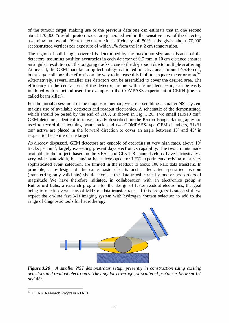
63
of the tumour target, making use of the previous data one can estimate that in one second
about 170,000 “useful” proton tracks are generated within the sensitive area of the detector;
assuming an overall Vertex reconstruction efficiency of 50%, this gives about 70,000
reconstructed vertices per exposure of which 1% from the last 2 cm range region.
The region of solid angle covered is determined by the maximum size and distance of the
detectors; assuming position accuracies in each detector of 0.5 mm, a 10 cm distance ensures
an angular resolution on the outgoing tracks close to the dispersion due to multiple scattering.
At present, the GEM manufacturing technology is limited to active areas around 40x40 cm2,
but a large collaborative effort is on the way to increase this limit to a square meter or more52
.
Alternatively, several smaller size detectors can be assembled to cover the desired area. The
efficiency in the central part of the detector, in-line with the incident beam, can be easily
inhibited with a method used for example in the COMPASS experiment at CERN (the so-
called beam killer).
For the initial assessment of the diagnostic method, we are assembling a smaller NST system
making use of available detectors and readout electronics. A schematic of the demonstrator,
which should be tested by the end of 2008, is shown in Fig. 3.20. Two small (10x10 cm2)
GEM detectors, identical to those already described for the Proton Range Radiography are
used to record the incoming beam track, and two COMPASS-type GEM chambers, 31x31
cm2 active are placed in the forward direction to cover an angle between 15º and 45º in
respect to the centre of the target.
As already discussed, GEM detectors are capable of operating at very high rates, above 105
tracks per mm2, largely exceeding present days electronics capability. The two circuits made
available to the project, based on the VFAT and GP5 128-channels chips, have intrinsically a
very wide bandwidth, but having been developed for LHC experiments, relying on a very
sophisticated event selection, are limited in the readout to about 100 kHz data transfers. In
principle, a re-design of the same basic circuits and a dedicated sparsified readout
(transferring only valid hits) should increase the data transfer rate by one or two orders of
magnitude We have therefore initiated, in collaboration with an electronics group at
Rutherford Labs, a research program for the design of faster readout electronics, the goal
being to reach several tens of MHz of data transfer rates. If this progress is successful, we
expect the on-line fast 3-D imaging system with hydrogen content selection to add to the
range of diagnostic tools for hadrotherapy.
Figure 3.20 A smaller NST demonstrator setup. presently in construction using existing
detectors and readout electronics. The angular coverage for scattered protons is between 15º
and 45º.
52
CERN Research Program RD-51.

64

65
4. GEOMETRY AND UTILIZATION OF AN IN-BEAM-PET
SYSTEM FOR CNAO
4.1 Introduction
In-beam PET is a non standard application of PET imaging and it has specific requirements
to be fulfilled. The positive experience of PET monitoring of carbon treatments at GSI yields
a new line of research of scanners suitable for in-beam PET. These investigations must be
facility dedicated, since each centre has some special features that may determine the final
detector choice. Among these, the beam field size, the patient bed volume and mobility, the
nozzle location, the time structure of the beam and the beam delivery technique are the most
relevant ones.
In the present Chapter, the study of a suitable scanner for the CNAO hadrontherapy centre is
carried out taking into account the specifications of the facility. On the bases of these results
a final design of the tomograph is proposed, consisting in two arcs separated by an angular
aperture. The width of the two gaps has been optimized by considering the extension of the
fragments exiting the patient downstream.
Because of the low activity induced in the treated patient, the sensitivity of the PET detector
is an important point. It has been estimated and compared to the sensitivity of a high
performance PET (HiRez from Siemens) used in nuclear imaging.
The studied in-beam PET scanner has been eventually used in the simulation of an in-beam
acquisition, in order to estimate the number of coincidences available during the treatment
and study possible optimization of the acquisition scheme.
The studies performed in the present Chapter put some light on the feasibility are the starting
point for the final detector unit choice.
4.2 Requirements for an in-beam PET for CNAO
The final scanner geometry must be optimized to fulfill the following conditions:
1. no collisions with any component: patient, patient bed and beam nozzle;
2. no obstructions to the primary beam and minimum overlap with the exiting
fragments from the patient;
3. easy access to the patient if an intervention is required.
These are the major limitations in the choice of the geometry. Other issues related to the
detector choice are treated in Chapter 5. Furthermore, the detector solution will be influenced
by the geometrical design of the scanner, since a lower geometrical coverage has to be
compensated by higher detection efficiency. At the same time, a compact detector helps in
increasing the mobility of the scanner.
The two possible scanner geometries are a full cylindrical scanner and a double-head scanner,
i.e. a cylindrical detector with two apertures (Fig. 4.1). A third solution considered in the first
analysis was a double-ring scanner, i.e. two ring detectors placed at a fixed distance. This
solution has been rejected because, first of all the Field of View (FOV i.e. the maximum axial
extent) of each ring does not contain the source, resulting in a lower global sensitivity.
Secondly, the access to the patient is more limited.

66
Figure 4.1. Three geometries considered for the CNAO PET scanner: standard full ring
cylindrical geometry with a rotation angle respect to the primary beam direction (left panel),
double-head scanner (right panel) and double-ring scanner (lower panel).
4.3 Optimization of the in-beam PET geometry for CNAO
In Phase 1 the CNAO facility features three treatment rooms, each one equipped with an
horizontal beam line; one of these has also a vertical line. The study has been performed for
this room, with both vertical and horizontal lines, since this choice puts more limitations to
the geometry. The following discussion is based on the present design of the treatment room,
but some parameters are still under discussion.
The isocentre height is 1200 mm. Both vertical and horizontal beam lines before reaching the
patient pass through the two monitoring devices, i.e. two nozzles. The two detector systems
have been developed by a group of Turin University and INFN Section 53
.
An almost cylindrical vertical system supports the beam diagnostic and the CT devices. The
end face of the support is at 50 cm from the isocentre. The horizontal line nozzle ends 50 cm
from the isocentre, hence the free space for the scanner is very limited with respect to both
the vertical and the horizontal detectors. The sensitive area of the beam detectors is 24 24
cm2
in order to cover the 20 20 cm2
maximum field with a certain margin. The patient bed,
mounted on a precision robot, has all 6 translational and rotational degrees of freedom.
The optimization of the scanner geometry for CNAO is studied in two steps: the first one is
centred on the limitations imposed by the nozzle location with respect to the isocentre and by
the patient size, while the second one takes into account further constraints coming from the
spatial distribution of the fragments exiting the patient.
In-beam-PET collision study
When considering the full ring scanner, its horizontal axis, passing through the isocentre,
must be rotated with respect to the primary beam direction to avoid any overlap with the
incoming beam (condition 2). The minimum rotation angle is obtained by imposing that at
53
Pecka A. et al., "The beam monitor system for the Centro Nazionale di Adroterapia Oncologica",
Nuovo Cimento 121 (2006) 869-877.

67
least the 24 24 cm2
sensitive area of the nozzle detector is not covered by any component of
the scanner. By rotating the scanner, the distance between the detector and the patient is
shorter, when the bed is perpendicular to the beam direction (Fig. 4.2).
Figure 4.2 Schematic drawing of the configuration used to carry out the study of the
collision of the in-beam PET scanner with the patient and with the nozzle. The set-up
corresponds to the minimum rotation angle of the scanner to avoid any overlap between the
scanner and the maximum field of the incoming particles.
Note that this is the geometry that puts the strongest limitation on the internal radius R of the
scanner. Such distance depends on the internal radius R and on the axial FOV a of the
tomograph. By imposing a minimum rotation angle, it is possible to study the dependence of
the collision-free area of the patient (i.e. a virtual cylinder of radius L ) on the geometry of
the scanner. Fig. 4.3 shows a schematic drawing of the bed and the patient to explain the
arguments to be considered when the virtual cylinder radius is chosen.
Figure 4.3 Positioning of the patient in the centre of the scanner. The radius L has to take
into account the mean size of the patient and possible displacement of the target with respect
to the isocentre, plus a certain margin to leave a reasonable comfort to the patient.
The radius L of the virtual cylinder around the patient is related to the scanner geometry and
to the size of the field of the incoming primary particles by the following equation:
arcsin[arctan( ) arctan( )]2
field
n int
n int
L aL d
d R,
,
= + (4.1)
where n int
d, is the transaxial extent of the scanner from the isocentre with respect to its
internal radius R and fieldL is the half-size of the primary particle field. The equation
assumes that the nozzle surface has a large extension, as shown in Fig. 4.2. For the
calculation fieldL was fixed at 12 cm, corresponding to the minimum rotation angle

68
configuration, as shown in Fig. 4.2, and to the maximum constraint to the geometry. The
parameter n int
d, is given by the first term of the following equation:
2 2
2 2( 2) cos[arcsin( )] ( )
( 2)field
field
n ext L
Ld a R dR cos a R
a R,= / + + , ,
/ + (4.2)
that gives the relation between the external maximum transaxial extent of the scanner given
by the sum of n int
d, and the radial depth dR of the scanner, depending on the rotation angle
( )fieldL a R, of the axis of the tomograph with respect to the beam direction.
Fig. 4.4 shows the dependence of the radius L of the collision-free volume around the virtual
patient as a function of the axial FOV of the scanner, for different values of the internal
radius R of the tomograph. For the minimum size the value L =25 cm was chosen, values of
the radius of the virtual patient smaller than this are represented in Fig. 4.2 by the red dashed
area.
Figure 4.4 Left panel: behaviour of the collision-free radius of the virtual patient as a
function of the axial FOV of the scanner, for different values of the internal radius of the
tomograph. Right panel: maximum transaxial extent of the scanner asa function of the axial
FOV for different internal radius. The red dashed area cover the forbidden region: the
patient radius cannot be shorter than 25 cm and the transaxial extent of the scanner cannot
by larger than 50 cm. In both pictures the scanner is in the minimum rotation angle
configuration, i.e. fieldL is 12 cm.
The external transaxial extent of the scanner n ext
d, is useful to evaluate the collision with the
nozzle by changing the geometry of the scanner. In this study the value of fieldL is 12 cm as
in the previous one. The right panel of Fig. 4.2 shows the dependence of n ext
d, on the size of
the axial length of the scanner, for different values of the internal radius R . In the plotted
curves the radial depth dR was set equal to 5 cm, assuming an extremely compact detector.
The value of n ext
d, cannot be larger than 50 cm, i.e. than the distance from the nozzle to the
isocentre, and the excluded region is represented in Fig. 37 by the red dashed area.
If one considers a value of L of 35 cm, that gives a reasonable comfort to the patient, the
maximum axial FOV of a 40 cm radius scanner is 10 cm whereas a 45 cm radius tomograph
cannot have an axial length larger than 20 cm. This last solution is interesting, but the right
panel of Fig. 39 shows that the distance to the nozzle is few cm. This poses important
constraints on possible detector choices requiring a very compact unit detector solution, as
the one investigated for the Heidelberg facility 54
.
54
Crespo P. et al., " First in-beam PET imaging with LSO/APD-array detecters", IEEE Trans. Nucl.
Sci. 51 (2004) 1389-1395.

69
Another possibility is represented by the double-head scanner. In this case, the angular gaps
between the two arcs must fulfill the second condition. The two angular apertures make
possible to keep the axis of the scanner always parallel to the axis of the patient. Therefore in
the case of a double-head tomograph, there are no geometrical constraints imposed by the
collision with the patient, while the problem of the distance to the nozzle still remains even if
less strict.
The absence of constraints on the internal radius and on the axial length imposed by the
patient makes possible to choose R =40 cm and a =30 cm, with few cm still remaining
between the scanner and the nozzle. It has also to be underlined that due to the presence of
the two gaps, the length of the projection of the scanner diameter in the horizontal plane is
again reduced, depending on the external radius and on the angular aperture.
When considering vertical treatments, since the distance of the nozzle to the isocentre is
equal to the horizontal line, the geometrical constraints are the same. To allow the vertical
beam to reach the patient, the full ring scanner would be able to rotate with respect to the
vertical plane. For the same reason, the double-head device must be free to rotate by /2 in
the ring plane, in order to move the two gaps in front of the vertical nozzle. To guarantee
different angle positioning of the patient bed, the scanner needs to be rotated with respect to
the vertical axis. A schematic drawing of a possible location of the double-head scanner in
the treatment room is presented in Fig.4.5.
Figure 4.5 Location of a dual-head scanner in the treatment room of CNAO, in different
set-ups. The horizontal and vertical nozzles are also drawn. The mechanical support is
schematically shown to underline the required degrees of freedom of the tomograph.
In conclusion a full ring scanner seems feasible, but with strong geometrical constraints on
the external radius, on the axial FOV and on the radial depth of the device. A dual-head
scanner is much more attractive due to the weaker limitations.
It is interesting to estimate the solid angle covered by the three scanners, according to what
previously discussed. A simple formula valuable in case of point source located in the centre
of the tomograph is:
cos[arctan( )]2
R
a= ,
/ (4.3)
where is the angular width between the two arcs (0 in case of a full ring scanner). The
geometrical sensitivity amounts to 0.11, 0.23 and 0.27 respectively for two full ring scanners
with R =40 cm and a =9 cm, R =45 cm and a =20 cm, and for a double-head scanner of 40
cm radius, 30 cm width and 40 degrees gap. The geometrical sensitivities are comparable in
the last two cases and the surface covered by the double-head scanner is only 3% larger than
the one of the second full ring scanner considered.

70
One of the major problems in case of a double-head scanner is the degradation of the PET
image due to the loss of events in the two gaps, as discussed in Ref. 55
. This problem can be
partially overcome by the development of dedicated reconstruction tools, as well as by a
clever acquisition method, as discussed in the last Section.
In-beam PET acquisition: Heidelberg facility versus CNAO
The very low activity induced in the patient, and hence the low number of useful coincidence
events available, asks for improvements not only in the detector performance but also in new
acquisition protocol. At the GSI pilot-project, in-beam PET data have been collected during
the off-time, due to the ramping-down and ramping-up of the synchrotron. This reduces the
number of acquired events typically by a factor 3.
For the Heidelberg facility, an intra-spill acquisition has been proposed to increase the
number of detected events. For a synchrotron having circumference L , a carbon ion beam of
energy E has a revolution period r
T given by the ratio between L and the speed of the ion
c . The radiofrequency (RF) period RF
T is equal tor
T h/ , where h is an integer named the
"harmonic number", equal to 1 for CNAO. Hence, we have:
2 2 2
0( )RF
L ET
c E m c
= . (4.4)
The elapsed time between two bunches is therefore given by RF
T divided by the number of
concomitant bunches within the same period.
For the GSI SIS, RF
T ranges between 480 and 250 ns by increasing the energy from 88.83
MeV/u up to 430.10 MeV/u56
. The prompt gamma background is strictly correlated to the
spill time microstructure. Therefore, any standard method for random coincidences
subtraction (i.e. delayed window) fails because of the time structure of the signal (Fig. 4.6).
Figure 4.6 Model of the time dependence of the background of un-correlated gammas due to
carbon ion beam microstructure 57.
Two methods have been proposed to acquire coincidences during the macropulses, between
consecutive micropulses, both related to the synchronization of the gamma coincidences with
the time microstructure of the beam either by using the RF-signal from the accelerator or of a
fast particle detector located in front of the target. With these approaches the gain in image
55
Crespo P. et al., " First in-beam PET imaging with LSO/APD-array detectors", IEEE Trans. Nucl.
Sci. 51 (2004) 1389-1395. 56
Crespo P., "Optimization of In-Beam Positron Emission Tomography for Monitoring Heavy Ion
Tumor Therapy", PhD thesis, Technischen Universitat Dresden, Germany (2005) 57
Parodi K. et al., "Random coincidences during in-beam PET measurements at micro-bunched
therapeutic ion beams", Nucl. Instrum. Meth. A 545 (2005) 446-458.

71
statistics lies between 70% and 90% , for the GSI 40% accelerator duty factor (the ratio
between the macropulse duration and the synchrotron acceleration cycle) 58
.
The impact of inter-spill acquisitions is more important for machines with smaller duty
factors.
At CNAO a slow beam extraction is performed by means of a betatron core. The use of a
betatron core to drive the resonant extraction enables to control very accurately both the
length and the intensity of the spill, but does not allow intra-spill acquisition.
4.4 Background particles in a in-beam PET system
A non negligible amount of fragments are forward directed with respect to the primary beam
direction, as shown in Fig. 4.7.
Figure 4.7 Angular distribution of neutrons, Z =1, Z =2 and Z =3 fragments, generated by
a 400 MeV/u carbon ion beam stopped in a 30 cm long PMMA target, on a 40 cm radius
scanner with 30 cm axial length. The distributions are computed with 500000 carbon ions.
58 Crespo P., PhD thesis (2005)

72
To reduce the background rate, the treatment field (20 20 cm2
) imposes an angular
aperture, between the two arcs of a 40 cm radius double-head scanner, of about 30°.
As shown in the figure, the background consists of low Z particles, neutrons and gammas,
and has to be kept into account in the final choice of the detector material: even if the
scintillating material is radiation hard, the flux of particles interacting in the crystal must be
as low as possible, to avoid material activation as well as tertiary fragment production.
For this purpose, the angular distributions of all relevant particles exiting the patient have
been computed by means of Geant4. The phantom is a 30 25 25 cm3 PMMA box. The
primary beam energy is the maximum achievable i.e. 400 MeV/u. Carbon ions enter
perpendicular to the target with a position ranging between -10 cm and +10 cm, in both the
lateral and transversal dimensions.
Around the target, and centred on it, a 40 cm radius scanner is located, spanning an angle
between - 2/ and + 2/ , with an axial length of 30 cm. The distribution of particles has
been calculated as a function of . For the considered double-head scanner of 40 cm radius
and 30 cm axial length, by considering a high intensity spill of 1 108 s
1, the rate of
fragments on the detector at different angles can be computed. The results are shown in
Fig. 4.8 for neutrons, Z =1, Z =2 and Z =3 fragments. The contribution of heavier nuclei is
negligible.
Figure 4.8 Average rate of fragments on the in-beam PET detector, at different angles
with respect to the primary beam direction. The rates are computed by considering a spill of
1 108s
1 carbon ions. The dotted line indicates the proposed half-angle of the gap.
Figure 4.9 Left panel: angular distribution of generated by a 400 MeV/u carbon ion
beam, on a 40 cm radius scanner. Right panel: energy distribution of all the gammas.

73
By considering a 40 degree angular aperture, the rate of protons and neutrons in the
proximity of the gap is about 2000 Hz mm2 each. The final rate of protons is obtained by
combining the calculation results of Fig. 4.7 with the correcting factor (about 2) estimated in
the Chapter 2 by comparing Geant4 with experimental data.
Figs. 4.7 and 4.8 show that fragments with Z higher than 2 do not constitute a major
problem, since they are all confined within ± 20 degrees. The rate of alfa particles is peaked
and, at 20°, is about 5% of the proton one. Instead the gammas of Fig. 4.9 have a flat
distribution. High energy gammas, above 511 keV, derive from nuclear de-excitations and
they are prompt, hence emitted within a short time window from the parent production. The
511 keV gammas come mainly from the annihilations of e+ produced by high energy
gammas.
4.5 Materials and methods for sensitivity assessment
The impossibility to acquire + -decays during the beam extraction limits the number of
coincidences during a treatment. Hence it is fundamental to assess and maximize the
sensitivity of the scanner. In this non-standard application of PET, and for pure inter-spill or
post-treatment acquisition, the performances of the scanner are not very difficult to obtain.
For instance, good random coincidence suppression and subtraction represents a major goal
in many scanners; in this case it is not important since the activity in the patient is rather low
(about 200 Bq cm3Gy
1).
The spatial resolution of the scanner is another important issue for standard PET application,
and it is mainly improved by using small pixellated detectors and high light yield crystals.
For an in-beam acquisition a high spatial resolution is not fundamental: 4-5 mm are sufficient
due to both the very low statistics (which anyway limits the precision) and because in
hadrontherapy treatment monitoring the aim is to compare the reconstructed image with the
simulated one.
The sensitivity is a more general parameter, which is mainly influenced by the scanner
geometry and the detector material properties (density and detection efficiency). Therefore it
is possible to estimate the sensitivity of a system without actually choosing the unit block
detector read-out. Timing performance and spatial resolution are of course important in the
final image quality, but do not affect the sensitivity of the device.
Geant4 application to tomographic emission
GATE is a simulation toolkit dedicated to PET and SPECT applications 59
60
. It is based on
Geant4 general purpose classes, involved in the construction of the geometry, the interaction
physics, the event generator and the visualization management. All these classes are defined
in the core layer. Here some additional classes specific to GATE are also defined, such as
that dedicated to time management. In order to make GATE a suitable computational
instrument also in clinical environment, all the functionalities provided by the classes are
available to the user through script commands.
The general simulation architecture is structured as following:
• definition of the scanner geometry,
59
Fiedler F. et al., "The Feasibility of In-Beam PET for Therapeutic Beams of 3He", IEEE Trans.
Nucl. Sci. 53 (2006) 2252-2259. 60
Jan S. et al., "GATE: a simulation toolkit for PET and SPECT", Phys. Med. Biol 49 (2004) 4543-
4561.

74
• definition of the phantom geometry,
• choice of the physics processes,
• initialization of the simulation,
• definition of the detector model,
• definition of the source,
• specification of the data output format,
• start of the acquisition.
In GATE there are different systems available (template of predefined geometries),
compatible with different data output formats. Currently there are five systems implemented
in GATE: one for SPECT, three for PET, and a generic system appropriate to model novel
tomographs. Once the system geometry and the phantom are set, the physics can be turned
on. It consists of radioactive decay (performed by the Geant4 radioactive decay module) and
electromagnetic physics. As in Geant4, GATE can use two different packages: the standard
and the low energy electromagnetic physics.
The most important part of the simulation is the description of the digitizer chain. It simulates
the electronics read out of a detector within the scanner. Once a portion of the scanner is
defined as sensitive, the interactions of the particles within this region are recorded. Each
detected event carries information about its history like vertex position, interactions in the
phantom (if it is defined as sensitive volume) and source type. The digitizer is organized as a
chain of modules that begins with the hit and ends with the single, which represents the
physical observable seen by the detector. The user can define several modules of the digitizer
chain to reproduce the behaviour of a real scanner, i.e. energy resolution, energy window,
spatial resolution, time resolution and dead time. Once the single is produced, GATE sorts
the coincidences, according to the user defined coincidence time window and multiple
coincidence policy.
Detector parameters: the NEMA NU-2 2001 protocol
The NEMA NU-2 2001 protocol has been used to evaluate the performance of a PET scanner
with the geometry, previously described, optimized for hadrontherapy in-beam acquisition 61
.
The report specifies standardized measurements, in order to make different PET scanner
performances comparable. The protocol aims to quantify relevant parameters of a PET
detector: scatter fraction, random fraction, spatial resolution, Noise Equivalent Count Rate
(NECR), image quality, and sensitivity. The present study is centred on the estimation of the
sensitivity, that is expressed as the rate of true coincidences detected for a given source
strength. A 700 mm tube of 4.8 mm diameter is filled of water mixed with the source of
activity cal
A . It is placed parallel to the scanner axis, in the centre of the detector. The line
source is surrounded by different metal sleeves. This ensures the annihilation of all emitted + , but at the same time increases the attenuation of the gammas. Several acquisitions with
different metal thicknesses are required so to extrapolate the count rate value to zero
thickness. The position of the line source can also be moved from the central axis, to estimate
the sensitivity as a function of the radial position of the source. The source activity must
guarantee a number of random coincidences less than 5% of the true detected coincidences.
The aluminium sleeves have the dimension reported in Table 4.1.
Table 4.1 Metal sleeves of the sensitivity measurement, according to NEMA NU-2 2001
protocol.
61
National Electrical Manufacturers Association, "Performance measurements of Positron Emission
Tomographs", NEMA Standards Publication NU-2 2001 (2001)

75
Total
number
Inside diameter
[mm]
Outside
diameter [mm]
Length
[mm]
1 3.9 6.4 700
2 7.0 9.5 700
3 10.2 12.7 700
4 13.4 15.9 700
5 16.6 19.1 700
At each acquisition j the count rate of true coincidences is given by:
0 ( 2 )j M j
R R exp Xμ= , (4.5)
where j
X is the metal thickness, and the two unknowns are M
μ and 0
R , respectively the
metal attenuation length and the count rate with no attenuation, to be fitted on measurements
(calculation) results. The system sensitivity is 0TOT cal
S R A= / .
Scanner geometry and acquisition
For this work, the first scanner system simulated was the HIREZ scanner (Siemens Medical
Solutions). Its main technical characteristics are summarized in Table 4.2.
Table 4.2 Technical characteristics of the HIREZ scanner and of the in-beam double-head
scanner.
Parameter HIREZ Double-head
Detector ring diameter 830 mm 800 mm
Detector material LSO LSO
No. of detector rings 39 65
Slice number 81 142
Crystal size 4 4 20 mm3 4 4 30 mm
3
Crystal array/block 13 13 13 13
Face of crystal block 52 52 mm2
52 52 mm2
No. of detector blocks 144 170
Avial FOV 162 mm 284 mm
Coincidence window 4.5 ns 4.5 ns
Energy window 425-650 keV 425-650 keV
Gap angle 0 deg. 40 deg.
The unit block detector is based on an array of 13 13 LSO crystals of 4 4 20 mm3. The
scanner ring diameter is of 830 mm, with 3 blocks arranged along the axial direction in a
spherical orientation, for a total number of 39 rings. The number of blocks per ring is 48 and
the scanner extends axially for 162 mm. Each block is read out by 4 PMTs, in an electronic
scheme that achieves 500 ps coincidence time resolution. The coincidence time window is set
to 4.5 ns. The energy resolution of the crystals has been set 15% . Fig. 4.10 shows the
simulated HIREZ system.

76
Figure 4.10 Simulation of a 3 rings HIREZ PET scanner, with the 700 mm line source
placed in the centre of the transaxial FOV.
The geometry of the in-beam dual-head scanner is based on the HIREZ unit block detector.
The length of the crystal is increased to 30 mm, to compensate the foreseen geometrical
sensitivity loss. According to the geometrical constraints discussed in the first Section, the
HIREZ detector design has been modified to match the in-beam PET requirements. The
angular gaps are 40 degrees and the detector ring diameter is reduced to 800 mm, therefore
the number of blocks per ring is reduced from 48 to 34. The number of blocks along the axial
direction has been increased to 5, with 274 mm axial FOV. The coincidence and energy
windows are kept equal to the standard HIREZ detector. The energy resolution of the crystals
is assumed to be 10% . In both systems, the takeWinnerOfGoods coincidence policy has been
adopted i.e. in a multiple coincidence event, only the two hits with the higher energy are
considered. The simulated double-head scanner is shown in Fig. 4.11.
Figure 4.11 Simulation of a 5 ring HIREZ scanner, arranged into a double-head geometry
with 40 degree gaps on opposite sides. The 700 mm line source is also drawn.
For the sensitivity assessment of the two systems, the line source was simulated as a water
filled tube with a homogeneous distribution of 18
F within it, that isotropically emits + . The
sleeves surrounding the source were made of aluminium. Once the acquisition is started, the
single and coincidences events detected are stored in ROOT format.

77
4.6 Validation for the HiRez system
The estimation of the sensitivity has been performed following the NEMA NU-2 2001
protocol previously described. Two acquisitions have been performed, with the line source in
the centre and at 10 cm radial offset from the centre of the transaxial FOV. The activity in the
line source was of 100 kBq, for 500 s long acquisitions.
The digitizer chain of the HIREZ scanner is not still optimally implemented in GATE, giving
some disagreements with respect to the count rate performance at high activity
concentrations. Since the activity used for our calculations is rather low, the present results
are reliable.
The calculated relative sensitivity for 5 aluminium thicknesses is given in Fig. 4.12, with the
regression fit line also plotted. The extrapolated absolute sensitivity at zero thickness is of
6.65 cps/kBq. If a certain span and ring difference (RD) in the coincidences selection is
introduces, we obtain a much more flat distribution in the central region of the scanner. For
the 27 RD implemented in HIREZ systems, the correction factor of the total sensitivity is
0.67 according to Ref. 62
, giving a new value of the absolute sensitivity of 4.46 cps/kBq, in
good agreement with the experimental value given in Ref. 63
: 4.87 cps/kBq.
Figure 4.12 Left panel: calculated count rate of the HiRez scanner as a function of the
aluminium thickness. The red line represents the regression fit given by Eq. 20. Right panel:
sensitivity profile of the HIREZ scanner, without span and RD. The line source is placed in
the centre (black triangle) and 10 cm apart (red circle) of the transaxial FOV.
Moving by 10 cm the source from the centre of the transaxial FOV, the sensitivity increases
by 2% , as also reported in the last Reference. The central and 10 cm away axial sensitivities
(without span or RD correction) for each slice are given in the right panel of Fig. 47. The
sensitivity of the HIREZ scanner is in reasonable agreement (10% ) with experimental data.
The difference between the two results (4.46 cps/kBq and 4.87 cps/kBq) can arise from some
features of the scanner not properly reproduced in the GATE geometry, like the packing
62
Eriksson L. et al., "Potential for a fifth generation PET scanner for oncology", IEEE Nucl. Sci.
Symp. Conference Record (2005) 63
Brambilla M. et al., "Performance Characteristics Obtained for a New 3-Dimensional Lutetium
Oxyorthosilicate-Based Whole-Body PET/CT Scanner with the National Electrical Manufacturers
Association NU 2-2001 Standard", J. Nuc. Med. 46 (2005) 2083-2091.

78
fraction of the unit block detectors. Anyway, the agreement is good and certainly sufficient
for the aims of the present work.
Sensitivity of a dual-head scanner
For the dual-head system the same procedure of the HIREZ scanner has been followed.
The calculated absolute sensitivity, extrapolated from the regression fit of Fig. 4.13, is 8.0
cps/kBq, 20% higher than the HIREZ system.
Figure 4.13 Left panel: calculated count rate of the dual-head scanner as a function of the
aluminium thickness. The red line represents the regression fit given by Eq. 20. Right panel:
sensitivity profile of the dual-head scanner, without span and RD. The line source is placed
in the centre (black triangle), 10 cm apart (red circle) and 30 cm apart (green square) of the
transaxial FOV.
Moving the line source 10 cm and 30 cm from the centre of the transaxial FOV, the
sensitivity decreases by 3% and 12% respectively (see the right panel of Fig. 4.13).
The higher sensitivity can be attributed partially to the wider axial FOV, but also to the
increased crystal length. The scintillator sensitivity of an LSO block can be expressed,
according to 64
, as:
( ) 0 05877 1 0754 [1 ( 0 5963)]scint
s exp s= . + . . , (4.6)
which gives the sensitivity for 511 keV gammas for different LSO thicknesses s , in the
energy window 0.425 and 0.650 MeV.
The computed value of the sensitivity of a 3 cm long crystal is 0.837, to be compared to
0.690 for a 2 cm long crystal. The increase in sensitivity is of about 47% if the coincidence
events are considered.
Thus the scanner studied satisfies the demand of increased sensitivity, despite the detector
block is still not optimized for an in-beam acquisition.
64
Eriksson L. et al., "Future Instrumentation in positron emission tomography", IEEE Nucl. Sci.
Symp. Conference Record (2006)

79
4.7 Simulation of the hadrontherapy treatment acquisition
The number of in-beam recorded coincidences foreseen for CNAO will be relatively low with
respect to other facilities with a beam microstructure that allows an intra-spill acquisition. It
is thus even surly essential to quantify the number of coincidences in a standard treatment.
A carbon ion treatment planning has been simulated by means of Geant4, described and
validated in Chapter 2.
A realistic treatment has been calculated by using the analytical code (ANCOD) implemented
in the C++ object oriented environment 65
(courtesy of F. Bourhaleb). This code is based on
the technique of inverse planning, that allows to estimate the best parameterizations and the
optimal treatment. ANCOD is implemented in the frame of the voxel scan technique with
pencil beams. Considering as input a CT and the target volume definition, ANCOD provides
for each field and for each elementary voxel the energy and the fluence of the pencil beam.
The simulated volume, made of PMMA ( =1.19 g/cm3), was divided into 128 128 51
voxels, of 1.96 1.96 3.0 mm3. The target was confined within this volume. A virtual
source was located 4 m far away from the treated volume. The pencil beam considered had
FWHM =4 mm, in both transverse directions.
The optimal values of fluence, energy and beam direction computed by ANCOD were given
as input to Geant4. The outputs of the simulation were stored in ROOT format. The stored
data were the dose delivered to each voxel of the volume and the isotopes produced (type and
decay position) with an additional flag for the voxel during whose treatment the isotope has
been produced.
The output data have been re-processed to reproduce the time delivery scheme of the
treatment.
The initial carbon ion fluences have been divided into spills 2 s long, each delivering 7 106
carbon ions, resulting into 30 spills to release the reference dose of 2 Gy. The carbon energies
decrease when moving the scanned beam from the distal layer of the target to the closer one.
The intensity of the beam is lower than the nominal value for CNAO ( 108 s
1) due to the
small size of the tumor (despite no protocol has still been defined for small tumor treatments
at CNAO) 66
.
The time structure of the incoming beam was assigned to the created isotopes by using the
recorded voxel flag. For each spill, three voxellized isotope maps have been created and
written in an ASCII data format compatible with GATE: they refer to 11
C, 10
C and 15
O, the
three isotopes whose production yields have been validated against experimental data.
An inter-spill pause of 2 s was assumed, resulting in a 50% duty factor (see Fig. 4.14).
Figure 4.14 Schematic drawing of the time structure of the simulated treatment. The dose is
delivered in 30 spills, with 2 s long macropulse and 2 s pause between each beam extraction.
The coincidence acquisition is performed during the inter-spill pauses.
65
Berga S. et al., "A code for hadrontherapy treatment planning with voxelscan method", Comp. Bio.
Med. 30 (2000) 311-327. 66
Pullia M., private communication

80
After each beam extraction, a 2 s long acquisition is started by means of GATE with the
double-head detector geometry described above (see Fig. 4.15).
Figure 4.15 Dual-head scanner for an in-beam acquisition simulation. The treated volume is
located in the centre of the FOV of the scanner (red box).
At each acquisition the isotope voxellized map, located in the scanner FOV, was given by the
sum of the activities induced in the last spill and in the previous ones, with a weighting factor
to take into account the time elapsed between the production spill and the acquisition time.
The full simulation scheme is depicted in Fig. 4.16.
Figure 4.16 Scheme of the simulation code.
The first acquisition has been performed during the beam extraction pauses with 5 additional
minutes after the end of the treatment. The scanner configuration is presented in Fig. 50, with
in the centre of the scanner the volume treated. The coincidences are selected with a narrow
energy window (0.425-0.650 keV as before) and a short coincidence time (4.5 ns). Fig. 4.17
shows the detected coincidences during the spill pauses.
Figure 4.17 Time distribution of the detected coincidences during the inter-spill acquisition.
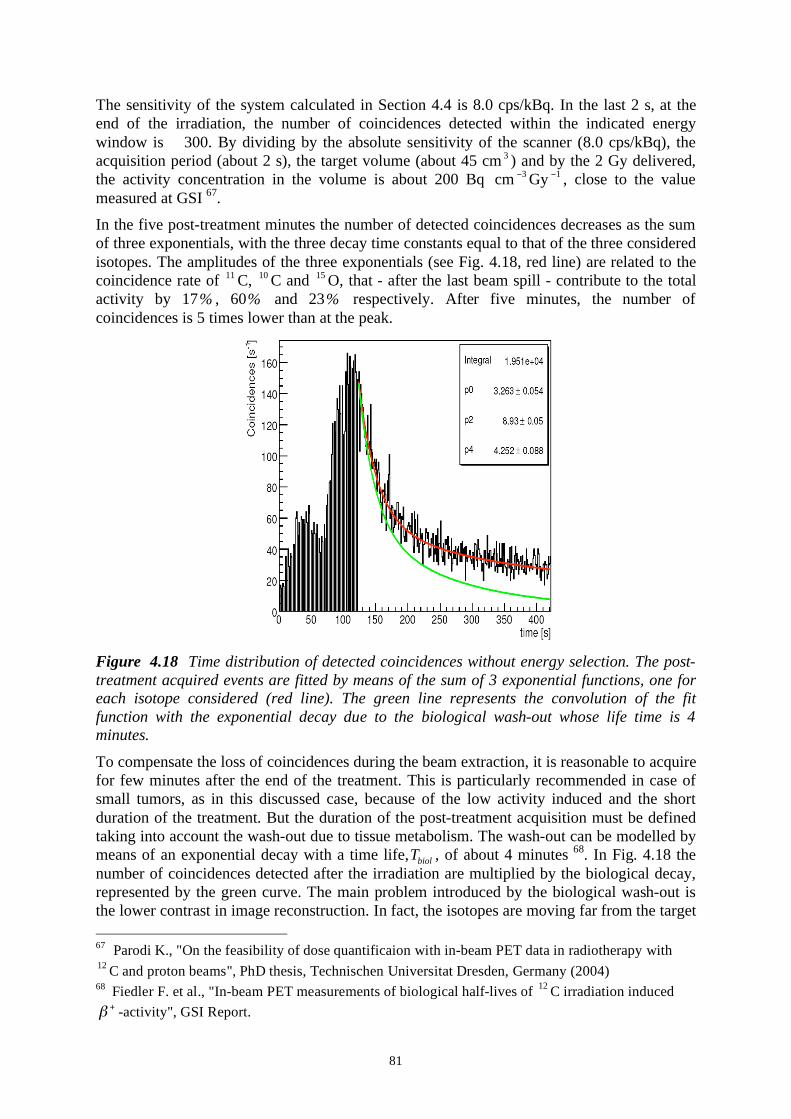
81
The sensitivity of the system calculated in Section 4.4 is 8.0 cps/kBq. In the last 2 s, at the
end of the irradiation, the number of coincidences detected within the indicated energy
window is 300. By dividing by the absolute sensitivity of the scanner (8.0 cps/kBq), the
acquisition period (about 2 s), the target volume (about 45 cm3) and by the 2 Gy delivered,
the activity concentration in the volume is about 200 Bq cm3Gy
1, close to the value
measured at GSI 67
.
In the five post-treatment minutes the number of detected coincidences decreases as the sum
of three exponentials, with the three decay time constants equal to that of the three considered
isotopes. The amplitudes of the three exponentials (see Fig. 4.18, red line) are related to the
coincidence rate of 11
C, 10
C and 15
O, that - after the last beam spill - contribute to the total
activity by 17% , 60% and 23% respectively. After five minutes, the number of
coincidences is 5 times lower than at the peak.
Figure 4.18 Time distribution of detected coincidences without energy selection. The post-
treatment acquired events are fitted by means of the sum of 3 exponential functions, one for
each isotope considered (red line). The green line represents the convolution of the fit
function with the exponential decay due to the biological wash-out whose life time is 4
minutes.
To compensate the loss of coincidences during the beam extraction, it is reasonable to acquire
for few minutes after the end of the treatment. This is particularly recommended in case of
small tumors, as in this discussed case, because of the low activity induced and the short
duration of the treatment. But the duration of the post-treatment acquisition must be defined
taking into account the wash-out due to tissue metabolism. The wash-out can be modelled by
means of an exponential decay with a time life,biol
T , of about 4 minutes 68
. In Fig. 4.18 the
number of coincidences detected after the irradiation are multiplied by the biological decay,
represented by the green curve. The main problem introduced by the biological wash-out is
the lower contrast in image reconstruction. In fact, the isotopes are moving far from the target
67 Parodi K., "On the feasibility of dose quantificaion with in-beam PET data in radiotherapy with 12
C and proton beams", PhD thesis, Technischen Universitat Dresden, Germany (2004) 68
Fiedler F. et al., "In-beam PET measurements of biological half-lives of 12
C irradiation induced +
-activity", GSI Report.

82
volume creating a diffuse background. The diffusion rate depends on the individual and on
the tumor treated, but it poses an upper limit to the duration of the post-treatment acquisition.
Even if the sensitivity of the chosen scanner is compatible (and even higher) than the one of
standard scanners, the presence of the two gaps limits the quality of the reconstructed image
introducing some deformations and artifacts. The in-beam scanner studied, at least for
treatment room equipped with both vertical and horizontal lines, must be able to rotate
around its horizontal axis in order to leave a free entrance window for the vertical beam (see
Fig. 4.19). Therefore, to compensate for the loss of events by the two gaps, it is possible to
perform a complementary post-treatment acquisition with the scanner rotated by 2/ with
respect to the inter-spill acquisition, when the position of the scanner is limited by the
irradiation set-up.
Figure 4.19 Dual-head scanner for an in-beam post-treatment acquisition, rotated of 2/ .
The treated volume is located in the centre of the FOV of the scanner (red box).
In Fig. 4.20 the sinograms of two different acquisitions are presented. In the first one (left
panel) the scanner gaps are kept in the same position during and after the treatment.
Figure 4.20 Sinograms reconstructed for two different acquisition scheme. Left panel: the
position of the two gaps in fixed during the inter-spill and post-treatment acquisition. Right
panel: the two gaps are rotated of 2/ between the inter-spill and post-treatment
acquisition.

83
The sinogram of the left panel is empty in the angular interval where the angular coverage is
missing. In the second case, after the inter-spill acquisition, the scanner is rotated by 2/ for
the5 minutes long post-irradiation acquisition. The area in the middle of the sinogram of the
right panel is now covered.
By combining events acquired in the two scanner positions, the final reconstructed image is
expected to be less affected by artifacts and therefore the monitoring of the treatment is more
accurate. The rotation angle can be optimized to obtain the higher sensitivity over the full
treated area, depending on the size of the treated tumor and its location with respect to the
centre of the tomograph.
The optimal way to implement this acquisition scheme needs a more detailed study
concerning the effective gain on the quality of the reconstructed image. To perform this study
a dedicated reconstruction algorithm is required.
4.8 Discussion of the results
The possible geometries of the in-beam PET scanner for the CNAO are a full ring and a
double-head scanner. In the first considered design, the geometrical constraints i.e. the
limitations on the internal radius and on the axial length of the tomograph, are imposed by the
size of the virtual patient, by the distance of the external surface of the nozzle to the isocentre
and by the extent of the incoming beam field and of the fragments exiting the patient.
Whereas when considering a double-head scanner, the two gaps make possible to keep the
axis of the scanner parallel to the patient axis, with weaker constraints on the geometry.
The limitations to the geometry of a full ring scanner have been extensively discussed leading
to a feasible geometry having R =45 cm and a =30 cm. Such a geometry would require an
extremely compact block detector in order to avoid any collision with the nozzle. In the case
of a double-head scanner, because of the absence of constraints with respect to the patient,
the chosen parameter values of the geometry are R =40 cm, a =30 cm and 40 degrees gap.
This solution puts less strict constraints on the size of the final detector and mainly for this
reason it is the geometry of choice.
Due to the low activity induced in the patient, the performance of the in-beam PET needs to
be first estimated with respect to the sensitivity i.e. the true coincidences count rate detection
capability. In order to estimate the sensitivity of the chosen PET in a rigorous way, the
NEMA NU-2 2001 standard protocol was used. The study was performed by means of
GATE, a Monte Carlo application to emission tomography. The sensitivity of the considered
scanner obtained by the calculations was 8.0 cps/kBq, to be compared to the computed value
of 4.46 cps/kBq for the HiRez PET from Siemens. The obtained sensitivity is high enough to
guarantee an efficient detection of the few coincidences available during an in-beam
acquisition.
The reliability of a treatment monitoring is affected by the quality of the acquired activity
map as well as by the proper simulation of the calculated one. The computed isotope
distribution map has to be convoluted with the scanner response and an accurate simulation
of the full acquisition can reduce computational artifacts in the simulated activity profile. For
this purpose, a full in-beam acquisition was simulated with the described double-head
scanner. A carbon ion treatment of a rather small (about 45 cm3) tumor was simulated by
means of Geant4 and the distribution of radioisotopes produced in the target was computed.
An inter-spill acquisition was simulated supposing 50% duty factor with 2 s long pause
between beam macro-pulses. The number of calculated coincidences at the end of the

84
treatment, within the energy window 425-650 keV, was 300 that, by considering the
sensitivy of the scanner leads to a value of 200 Bq cm 3 Gy1, in agreement with the value
provided by GSI.
The main disadvantage of a double-head scanner is the possible presence of artifacts and
distortions of the reconstructed image, due to the lack of a full angular coverage. To
overcome this problem, a few minutes post-treatment acquisition has been suggested with the
scanner rotated in order to guarantee a more uniform coverage of the treated volume.

85
5. IN-BEAM-PET WITH CRYSTALS
5.1 Introduction
PET is a well-known diagnostic technique to interrogate cancer and cardiac biology and
serves as a critical component of molecular imaging. The continuous developments in
detector and computing reflecting the growth of High Energy Particle Physics experiments,
contribute to increase the performances of such devices.
Proton-rich isotopes may decay via positron emission, in which a proton in the nucleus
decays to a neutron, a positron and a neutrino. As positrons travel through human tissue they
give up their kinetic energy principally by Coulomb interactions with electrons. When the
positrons reach thermal energy, they start interacting with electrons either by annihilation,
which produces two 511 keV photons, anti-parallel in the positron frame, or by formation of
a hydrogen-like orbiting couple called positronium.
In its ground state, positronium has two forms: ortho-positronium, where the spins of the
electron and positron are parallel, and para-positronium, where the spins are anti-parallel.
Para-positronium again decays by self-annihilation, generating two anti-parallel 511 keV
photons. Ortho-positronium self-annihilates by emission of three photons. Both forms are
susceptible to the pick-off process, where the positron annihilates with another electron. Free
annihilation and the pick-off process are responsible for over the 80 % of the decay events.
Variations in the momentum of the interacting particles involved in free annihilation and
pick-off process result in an angular uncertainty in the direction of the 511 keV photons
around 4 mrad in the laboratory frame of reference. In a PET camera of 1 m diameter and an
active transaxial Field Of View (FOV) of 0.6 m this results in a positional inaccuracy of 2-3
mm.
The two 511-keV annihilation photons have a mean attenuation length of 10.4 cm in water.
The human head and chest have dimensions of the order of 20 cm; this means that in whole-
body PET only 15 % of photon pairs have no interaction in biological tissue. In most cases,
one or both photons will be either absorbed or Compton scattered. In PET scanners, each
detector generates a timed pulse when it registers an incident photon. These pulses are then
combined in coincidence circuitry, and if the pulses fall within a short time window, they are
deemed to be coincident. A coincidence event is assigned to a line of response (LOR) joining
the two relevant detectors. In this way, positional information is gained from the detected
radiation without the need for a physical collimation (septa). This is known as electronic
collimation and it has two major advantages over physical collimation: the improved
sensitivity and the improved uniformity of the point source response function (psrf).69
5.2 Scintillators and detectors
Inorganic scintillator crystals are the most commonly used detectors for PET. Annihilation
photons interact within the scintillator through Rayleigh, Compton and photoelectric effects.
Only the latter two release energy to the detector, making the photons “detectable”. The
absorbed energy causes the crystal lattice to make a transition to higher energy state, from
which it may undergo decay after a characteristic time by emitting lower energy photons.
69
http://depts.washington.edu/nucmed/IRL/pet_intro/toc.html
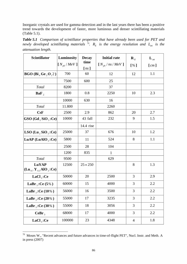
86
Inorganic crystals are used for gamma detection and in the last years there has been a positive
trend towards the development of faster, more luminous and denser scintillating materials
(Table 5.1).
Table 5.1 Comparison of scintillator properties that have already been used for PET and
newly developed scintillating materials 70. E
R is the energy resolution and att
L is the
attenuation length.
Scintillator Luminosity
[ phN MeV/ ]
Decay
time
[ ns ]
Initial rate
[ phN ns MeV/ / ]
RE
[% ]
Latt
[ cm ]
BGO (Bi4
Ge3O
12 ) 700 60 12 12 1 1.
7500 600 25
Total 8200 37
BaF2
1800 0 8. 2250 10 2 3.
10000 630 16
Total 11 800. 2260
CsF 2500 2 9. 862 20 2 7.
GSO (Gd2
SiO5:Ce) 10000 43 fall 232 9 1 5.
14 4. rise
LSO (Lu2
SiO5:Ce) 25000 37 676 10 1 2.
LuAP (LuAlO3:Ce) 5800 11 524 8 1 1.
2500 28 104
1200 835 1
Total 9500 629
LuYAP
(Lu0 7.
Y0 3.
AlO3:Ce)
12500 25 250+ 8 1 3.
LaCl3:Ce 50000 20 2500 3 2 9.
LaBr3:Ce (5% ) 60000 15 4000 3 2 2.
LaBr3:Ce (10% ) 56000 16 3500 3 2 2.
LaBr3:Ce (20% ) 55000 17 3235 3 2 2.
LaBr3:Ce (30% ) 55000 18 3056 3 2 2.
CeBr3 68000 17 4000 3 2 2.
LaCl3:Ce 100000 23 4348 4 1 8.
70
Moses W., "Recent advances and future advances in time-of-flight PET", Nucl. Instr. and Meth. A
in press (2007)

87
The luminescence processes occurring in inorganic scintillators are of two types, according to
the time scale in which light emission takes place: fluorescence, if the time constant is shorter
than 108 s, and phosphorescence or afterglow, with emission time larger than 10
8 s and for
some materials as large as several hours. The majority of inorganic crystals are impurity-
activated, as alkali halides activated by heavy metals like Thallium (CsI:Tl), or oxides doped
with rare earth ions as Cerium (LSO:Ce). Other scintillators are self-activated, like BGO or
BaF2
, by an excess of one of the constituents.
Gamma interactions
Gammas interact with matter by different processes: coherent scattering, Compton scattering,
photoelectric effect and pair production. The total absorption coefficient is the sum of the
coefficient of each process and is given by:
coherent photoelectric compton pairμ = + + + . (5.1)
The resulting μ is called the linear attenuation coefficient.
Among all the possible gamma interactions, for detection purposes the most effective process
is the photoelectric one, since all the energy of the incoming gamma is transferred to a single
electron. The photoelectric process is enhanced for absorbers with high atomic number Z ,
and this is the reason for which the tendency in scintillators is towards the development of
higher Z materials. No single analytic expression is valid for the probability of photoelectric
absorption per atom over all ranges of the gamma energy E and Z . A good approximation
is given by the following equation:
3 5
nZ
E., (5.2)
where n varies between 4 and 5.
Mechanisms in inorganic scintillators
The efficiency of a scintillator to convert the energy of the incident gamma into light
depends mainly on three parameters:
S Q= , (5.3)
where , S and Q are the conversion, transfer and luminescence efficiencies respectively71
.
At the very beginning of the interaction process, the ionization event creates an inner shell
hole and an energetic primary electron is freed with subsequent radiative or non-radiative
decay, and inelastic electron-electron scattering. This first stage occurs in the first 1015
-
1013
s and it is related to the parameter that describes the efficiency of the conversion
process. The energy Ee of the electron, set in motion by the gamma, generally allows to
produce a large number of electron-hole (e -h) pairs. If the energy required to produce an
e -h pair is =kEg, where E
g is the band gap energy and k ranges between 2 and 7, the
achievable number of pairs of charge carriers is Ee/kE
g.
When the electron energy becomes lower than the ionization threshold, it (or the hole) can
thermalize by means of intraband transitions and energy loss to phonons. The charge carriers
can remain as a diffuse band states, become trapped on defects and impurities, become self-
71
Lempicki A.et al., "Fundamental limits of scintillator performance", Nucl. Instr. and Meth. A333
(1993) 304-311.

88
trapped by the crystal lattice, or form free and impurity-bound excitons. During this second
stage luminescent centres can be excited by impact with hot electrons or sequential electron-
hole capture. The energy transfer process, related to the parameter S, ranges from less than
1012
to more than 108 s, and it is responsible of the rise time of the scintillation light.
Hence S is related to the efficiency of e -h and excitons to migrate and transfer their energy
to luminescence centres.
In the third stage, the excited luminescent sites return to their ground state by non-radiative
quenching processes or by emitting photons. The radiative process can last 109 s for e -h
recombination or can take several minutes for highly forbidden transitions. At this stage,
many processes can limit the luminescence efficiency Q, like non-radiative transitions or
processes related to energy transfer 72
. For example, for NaI:Tl, typical values for , Q and S
are 0.88, 1.0 and 0.59, leading to a total efficiency of 0.52. At the end of the three stages,
the number of photons produced is given by:
e
p e h
g
En n S Q S Q
kE= = . (5.4)
A typical value for NaI:Tl is 75,000 ne h
, to be compared with 38,000 N ph /MeV.
From Eq. 5.4 it is clear that the lower is the band gap energy the higher will be the light
output, but in this extreme case of small g
E the probability that an optical photon is
reabsorbed by the gap is high and this consequently reduces the light output 73
.
Energy resolution
In order to resolve the energies of the incoming gammas, a good energy resolution is an
important requirement. The average amount of charge 0
Q delivered by a Photomultiplier
Tube (PMT) is:
0
Q N p M= , (5.5)
where N is the average number of optical photons produced by the scintillator after a gamma
interaction, p is the average transfer efficiency of light from the crystal to the first dynode of
the PMT (i.e. the probability that a photon from the scintillator results in the arrival of a
photoelectron at the first dynode) and M is the mean electron multiplication factor of the
PMT 74
.
The energy resolution R is a feature of the gamma energy E and is defined as the ratio
between the FWHM of the peak and its maximum. The variance (0
Q ) is calculated as:
02 36 ( )
FWHM
ER Q
E= = . . (5.6)
The variance can be approximated as:
0
1 1 ( )( ) ( ) ( )
MQ N p
N Np
++ + . (5.7)
72
Lecoq P. et al., "Inorganic scintillators for Detector Systems- Physical Principles and Crystal
Engineering", Berlin Heidelberg, Springer-Verlag (2006) 73
Derenzo S. E. et al., "The quest for the ideal inorganic scintillator", Nucl. Instr. and Meth. A 505
(2003) 111-117. 74
Dorenbos P., et al. "Non-proportionality in the scintillation response and the energy resolution
obtainable with scintillation crystals",IEEE Trans. Nucl. Sci. 42 (1995) 2190-2202.

89
The term in brackets in Eq. 5.7 refers to fluctuations in the number N of photons which are
not due to pure Poisson statistics. The second term ( )p is the fluctuation in the photon
transfer and the last term is the photomultiplier variance, mainly due to gain fluctuations.
From Eqs. 5.6 and 5.7, the energy resolution can be written as:
2 2 2 2
i p MR R R R= + + , (5.8)
where Ri is the intrinsic resolution of the scintillator, dominated by non linearities of the
light output for different gamma energies and by the presence of impurities or
dishomogeneities in the crystal. In modern PMTs Rp
can be neglected, while RM
is
proportional to the square root of the last term of Eq. 5.7, i.e. is inversely proportional to the
number of electrons hitting the first dynode.
Light detectors
The light collected in crystals is converted into measurable electrical voltage pulse in
commercial PET scanners usually by photomultiplier tubes (PMTs). These devices convert
the scintillation light into a very weak electrical signal at the photocathode, which is then
amplified through an efficient low noise avalanche cascade process. This process repeats
until amplifications of the initial voltage pulse of > 105 are achieved. The high gain, stability
and low noise of PMTs have rendered these devices the standard ones used in PET scanners.
The most common detector configuration used in commercial scanners couples each detector
block to four PMTs with light sharing, providing the position of the conversion with an
accuracy of a few mm or better.
The development of multi-anode position-sensitive photomultiplier tubes (PSPMTs) of
square shape allows accurate positional and energy information to be derived from the PMT
itself. These devices utilize the positional information of the electron ejection site from the
photocathode, which are steered into different compartments within the PMT tube.
The spatial resolution of typical PET scanners is limited by the scintillator PMT block design
and the low quantum efficiency of PMTs. To achieve a higher spatial resolution, a higher
segmentation of scintillators is required with the ability to readout each segment
independently.
Solid-state photodiodes, in contrast to PMTs, are small, operate at much smaller voltage and
exhibit higher quantum efficiencies. This allows the possibility of easy read-out patterns of
the sensitive area, especially through the introduction of monolithic pixilated photo-detectors.
The most important silicon planar photo-detectors are silicon p-i-n photodiodes (PDs),
avalanche photodiodes (APDs) and silicon drift photo-detectors. A recent development, the
silicon photomultiplier (SiPM) is receiving a lot of attention for PET imaging applications,
due to its high gain and promising low cost; at the present time however it is not yet
commercially available in sizes and quantities suited for a PET project.
5.3 Specification of the in-beam-PET device
The basic detector technologies used for in-beam-PET imager are similar to those used for
standard systems. However the results of the simulation discussed in the previous Chapter
indicate some major differences in the requirements and thus in the design:
1. The true counting rates, defined as the total number of 511 keV collinear photons due
to positron-emitting isotopes, are of the order of 200 Bq Gye-1
cm-3
and are smaller by
at least two orders of magnitude than in normal PET diagnostics;
90
2. The relatively long range of the emitted positrons, mainly due to 11
C and 15
O, is larger
than the one of 18
F used in standard PET examinations, and limits the achievable image
resolution;
3. The large background of charged and neutral particles emitted during a treatment with
carbon ions, peaked in the forward direction but conspicuous over the full solid angle,
implies large singles rates in each detector element and masks the true coincidence
signal;
4. The large flux of secondary particles may cause radiation-induced aging problems in
the detector elements close to the forward direction;
5. The short decay time of the beta-emitting isotopes implies that data have to be
collected during and immediately after the irradiation, i.e. during the ramping down
and up of the synchrotron magnets and, if necessary, for a few minutes before the
patient leaves the irradiation position.
Points 1 and 2, in particular, suggest a detector design which is very different from the ones
developed and constructed by many groups for the so called “animal PETs”. In the former
case millimetre accuracies combine with enormous counting rate and, thus, not very large
solid angles are sufficient. For a PET-on-beam device the statistical error on the number of
positron annihilations is important and resolution is not a major issue.
Point 3 and 4 require that no detector be placed “forward”, i.e. close to the direction of the
incoming beam which at CNAO covers a 20x20 cm2 surface.
The remarks above suggest a device design with the following main properties:
- Detector thickness between two and three absorption lengths, to provide efficient
detection;
- Fast detector elements with, if possible, a good energy resolution, to optimize the signal-
to-noise ratio, or NEC (Noise Equivalent Count);
- Short intrinsic time of the detector elements, permitting a coincidence width of ten
nanoseconds or shorter, in order to improve the effective count rate in presence of a large
non-correlated background;
- Detector elements in the forward cone which are robust to radiation damage, due in
particular to high gamma and neutron fluxes, so that the system can stand the high
background during treatments;
- Data recording taking place only in the time intervals between spills;
- Methods for coarse determination of the depth of interaction, which may be needed for
some geometry, in order to reduce the parallax error.
A scintillator solution based on LSO (Lanthanum Orthosilicate) as scintillator satisfies the
above requirements at best, and is commercially available in large quantities, being the
material of choice for the present generation of PET/SPECT scanners.
For the scintillation photon detectors, the choice is wider, from conventional photomultipliers
to solid-state devices. However, the requirement of a coarse determination of the depth of
interaction, considerations of cost and commercial availability indicate a preference for the
readout of multi-anode photomultipliers (MAPM) or Avalanche Photodiodes (APD) arrays.
The already mentioned recently developed Silicon Photomultipliers (SiPM) have also to be
considered, owing to their large gain, which eliminates the need of using channel amplifiers.
In the long term, this would be a better choice, but for the time being SiPM are not
commercially available in the sizes needed for a PET scanner.
In general, for in-beam-PET, the most important quantity to be mapped is the beam
penetration or range in the body. The detector geometry has therefore to be optimized for the

91
measurement of the positron-emitting nuclei density in the direction of the beam while
leaving an opening for the entry port of the beam with its halo, and the most intense part of
the forward secondary radiation.
5.4 Review of in-beam-PET systems
The first attempts at operating an in-beam positron tomography at Lawrence Berkeley
National Laboratory had to be abandoned due to detector activation arising most probably
from the flux of secondary particles caused by passive beam shaping techniques. To avoid
this problem, a dual-head positron camera was installed at GSI. This was done after careful
investigations of imaging capabilities of the selected tomograph75
. The In-beam-PET
acquisition was synchronized with the time structure of particle extraction.
The BASTEI detector (Beta Activity Measurements at the Therapy with Energetic Ions),
installed at GSI, consists of two heads having a 42x21 cm2 front area each. Each sphere,
forming a calotte of 41.5 cm radius, was built from block detectors of the ECAT EXACT
tomograph from CTI PET Systems Inc. The block units of this detector are made of inorganic
scintillator BGO crystals coupled to photomultiplier tubes (PMT). Each block is subdivided
into 8x8 BGO with 6.75x6.75 mm2 front surface each and 20 mm depth and is read by four
PMT. Each head consists of 8x4 block detectors. This detector arrangement consists of about
4.2 million lines of response (LOR) crossing the field of view (FOV) of the scanner. For the
limited-angle tomograph described, a dedicated, attenuation correcting, maximum likelihood
expectation maximization (MLEM) algorithm was developed76
.
The positive clinical impact of the GSI tumour therapy pilot project triggered the construction
of a hospital-based hadron therapy facility HIT in Heidelberg, with in-beam PET expected to
monitor more delicate radio-therapeutic situations.
In order to improve In-beam-PET by optimizing the detector arrangement, both a closed ring
and a dual-head scanner have been considered. From simulations performed, both dual-head
tomograph studied ( =46 deg. and =100 deg.) clearly show reconstructed image
degradation although the FOV completely covers the irradiated volume.
Figure 5.1 The PET scanner installed at GSI without (left) and with (right) its housing.
75
Pawelke J. et al, Phys. Med. Biol. 41 (1996) 279. 76
Crespo P., Shakirin G. and Enghardt W., Phys. Med. Biol. 51 (2006) 2143.

92
This result is due to less information arising from the gap between the detector heads. The
benefits of a closed-ring tomograph are evident especially in case of a larger volume treated.
The main problem occurring in the latter case concerns the constraints on the geometry of the
tomograph due to the patient couch dimensions and the beam width, with a maximum
window deliverable of 20x20 cm2. Evaluating different combinations, some optimal
configurations seem to be realizable although a very compact scanner is required with a
limited radial depth including detectors, front-end electronics, cabling and support structure.
To satisfy this requisite a LSO/APD array as possible detector for in-beam-PET has been
proposed and studied77
. The prototype consists of 32 LSO crystals coupled to the 4x8 pixels
of a Hamamatsu S8550 avalanche photodiode array. The dimensions of a crystal after manual
polishing are 2.34 ± 0.14 x 2.30 ± 0.15 x 15 ± 1 mm3. Each crystal had all faces but one
wrapped with Teflon tape, with the non-covered face coupled by silicon glue to each pixel pf
the array (see Fig. 6.3). The Hamamatsu APD array shows good performance but a low
internal gain (<80) and as a consequence a low signal-to-noise ratio, that can be improved by
means of low noise preamplifiers78
.
Figure 5.2 Detector block made of 32 LSO crystal wrapped by Teflon and coupled one by
one to an APD pixilated matrix.
A first aspect analyzed concerns the check of the stability of the detectors and the influence
of the beam on their performance since the imaging capabilities of these detectors are
expected to be mostly influenced by the particle and photon flux generated by nuclear
reactions. Two blocks as described above were developed and a 68
Ge line -source positioned
between them. Imaging of this line source was performed before, during and after irradiating
phantoms (9x9x20 cm3) of PMMA. A pencil-like beam of 341 MeV/u carbon ions was used.
The phantoms were positioned outside the FOV of the LSO/APD detectors. The mean energy
resolution obtained on the photo-peak is 15.5 ± 0.4 % FWHM, while the measured
coincidence time resolution is 6.2 ± 0.2 ns FWHM. An image of the depth distribution of +
decaying radionuclides created in a phantom stopping the high-energy carbon ion beam was
successfully performed. This was a major achievement since it demonstrated: 1) the in-beam
capability of this detector type and 2) the sufficient radiation hardness of such detectors to be
operated at a radiotherapy treatment site.
5.5 Description of the chosen device and motivations
The results obtained in the previous Chapters underline the key requirements that an in-beam-
PET unit detector has to satisfy. Of course a good spatial resolution is desirable, but first of
all a high detection capability is necessary due to the low counting rate. This requirement
implies a high scanner sensitivity, which reduces the geometrical loss. In this Chapter the
77
M. Kapusta et al, IEEE Trans. Nucl. Sci. 51 (2004) 1389. 78
P. Crespo, M. Kapusta, J. Pawelke, M. Moszynski and Enghardt W., IEEE Trans. Nucl. Sci. NS51
(2004) 2654.

93
prototype of a new unit block detector is described. A preliminary study of the device has
been carried out by means of an optical transport Monte Carlo code, LITRANI. Some
preliminary experimental results are described in the last Sections.
Conventional PET cameras are a convenient starting point. Since long time the favored
solution has been to couple a segmented block of BGO with 4 PMTs (see Fig. 5.3).
Figure 5.3 Anger logic scheme read-out for a BGO block detector coupled to four PMTs 79
.
The crystals are obtained from a unique scintillator block and several grooves of variable
lengths in the BGO act as light guides that improve the position accuracy of the four-PMT
position logic 80
. The X and Y coordinates of the hit crystal are calculated with the Anger
logic, according to the following equations:
A C B D A B C D
X YA B C D A B C D
+ += = ,
+ + + + + + (5.9)
where A , B , C and D are the outputs of the four PMTs. The main drawbacks of these
detectors are the uncertainty in the determination of the interaction point (the spatial
resolution provided is of 5-6 mm), the limited counting rate and the difficulty in
distinguishing Compton scattering events 81
.. In fact, the total energy of the gamma can be
deposited in a single photoelectric event or in multiple Compton and photoelectric
interactions. In this last case, the Anger logic fails to localize the interaction point since the
signal is more spread among PMTs than in a single energy deposition.
The modern trend in PET detector development is to use 2D-arrays of small crystals
individually coupled to pixellated photodetectors. In this way a higher spatial resolution is
easily achieved, because uncertainties in the identification of the hit crystal are avoided.
Another important issue, that triggered new detector research, is the capability of the device
to determine the Depth Of Interaction (DOI), in order to improve the image quality at the
periphery of the Field Of View (FOV). Many approaches have been studied like the
phoswich detector, that exploits the pulse shape layer discrimination technique, and double-
end read-out schemes, that compare the signal amplitudes arriving to the two end of each
detector [82
. This last technology has the drawback of a substantial increase in cost.
79
Unversity of Washington Web page: http://depts.washington.edu/nucmed/IRL/pet _ intro/,
"Introduction to nuclear physics". 80
Phelps M., "Molecular Imaging with Positron Emission Tomography", Annu. Rev. Nucl. Part.
Sci52 (2002) 303-338. 81
Korzhik M. et al., "Development of scintillation materials for PET scanners", Nucl. Instr. and
Meth.. A 571 (2007) 122-125. 82
Auffray E. et al., "The ClearPET project", Nucl. Instr. and Meth. A527(2004)171-174

94
In this work a different detector solution was studied, based on a continuous scintillating
material coupled to a position sensitive photodetector. This simple device, requires indeed
sophisticated signal processing to localize the interaction point ( X ,Y , Z ) and achieve a
spatial resolution good enough for in-beam-PET.
To reduce the parallax error for off-normal incidence photons, a coarse measurement of the
depth of interaction is needed, particularly for the proposed double ring solution. Several
methods have been used for measuring the DOI:
- Dividing thick crystals in shorter elements with individual readout;
- Using the “phoswitch” scheme, where two or more crystals having different signal
decay time are glued together on the same sensor, the DOI being estimated from a
measurement of the pulse width or rise time;
- Measuring the light signal sharing on long crystals, read from both sides.
For the CNAO in-beam-PET it has been proposed an improved version of the last solution,
made possible by the availability of multi-anode photomultipliers, avalanche photodiode and
silicon photomultiplier matrices.
The basic idea is to use large crystals read out on one wide face with a multi-pad sensor,
recording for each event the full profile of the collected light. To avoid the spread due to
internal reflections, all faces of the crystal except the one read out can be either blackened or
de-polished. For a localized flash of light within the crystal, produced by a photon
conversion, the centre of gravity of the distribution, recorded on the sensor’s pads, provides
the position of the conversion in the x-y projection, while its relative width increases with the
distance from the sensor, or DOI.
One can start by considering a typical light yield of about 15,000 photons emitted at the
conversion point by a 511 KeV gamma. An estimate of the expected signal, taking into
account the solid angle seen by the wide face (10 to 50%, depending on the DOI), the
quantum efficiency of the PM (20%) and the DOI-dependent sharing between pads gives
between a few tens and a few hundreds photoelectrons collected by one pads, well above the
PM noise.
Fig. 5.4 shows schematically the setup used for the simulation studies and the experimental
measurements to be discussed in the following.
Figure 5.4 Scheme of a PET detector module, made of many thin crystals mounted over a
multi-pad detector. The photon distribution determines the longitudinal and depth coordinate
of the scintillation point.

95
The scintillation material choice has been led by several considerations. First of all the
material has to be dense. Moreover, the material has to be fast, to keep small the integration
time of the signal. Last, but not least, the crystal has to have a large scintillation yield.
The bromides LaBr3 is attractive: this crystal has an excellent light yield and a fast decay
time (15 ns), but unfortunately it is hygroscopic, very expensive and it has a small attenuation
length (2.2 cm). Other two interesting materials are LuAP and LuYAP. They are fast and
dense, relatively bright and they have a high light absorption. Another possibility is LYSO,
which has been actually chosen not only because of the high light output and the fast decay
time, but also because these crystals present a high level of transparency and homogeneity.
Concerning the photodetector, several devices have been considered among all technologies
presently available (Table 5.2).
Table 5.2 Photon detectors properties [84]. PDE is the photon detection efficiency.
Solid-state technology Vacuum technology
APD SiPM HPD MA-PMT MCP-PMT
PDE Blue 50% - 20% 20% 20%
PDE Green-
Yellow
60-70% - 40% 40% 40%
PDE Red 80% - < 6% < 6% < 6%
Timing/10 ph.e. few ns tens ps 100 ps 100 ps 10 ps
Gain 1000 105-10
6 3-8 10
3 10
6-10
7 10
6-10
7
Operation
voltage
100-500 V < 100 V 20 kV 1 kV 3 kV
Operation in B Yes Yes axial B 4 T < 103 T axial B 2 T
Sensitivity/ph.e. 10 1 1 1 1
An Avalanche PhotoDiode (APD) combines the advantages of a PIN photodiode (small,
cheap, high QE, insensitivity to magnetic field) and those of a photomultiplier (gain and
speed). Photons create electron-hole pair in the thin p-doped silicon layer of an APD. The
electrons drift to the high field region at the p-n junction where they start, by ionization, an
electron avalanche. The gain, that can be 1000 or more, is very sensitive to the stability of the
applied voltage and to temperature fluctuations
The Silicon Photomultiplier (SiPM) of Fig. 5.5 would be a good candidate.
Figure 5.5 Schematic drawing of a SiPM made of 30x30 m2 cells.

96
It is a densely packed matrix of small, Geiger-mode avalanche photodiode (GAPD) of 30-
50 μ m side, with individual quenching resistances for each cell. It results in a compact
device with a fast timing ( 50 ps), high gain (105-10
6), single photoelectron resolution and
low noise 83
. But, even if SiPM would be a better choice, for the time being they are not
commercially available in the sizes needed for a PET scanner. Instead Hybrid Photon
Detectors (HPD) are available and combine the sensitivity of a vacuum PMT with the
excellent spatial and energy resolutions of a silicon sensor. A single photoelectron ejected
from the photocathode is accelerated through a potential difference of 20 kV before it
impinges on the silicon anode. Since the gain is achieved in a single step one can expects to
have an excellent resolution. HPDs can be segmented down to 50μ m. A prototype with 208
anode pixels, designed for an axial PET, is currently under construction at CERN 84
.
Other two devices have been considered: the Multi-Anode PMT (MA-PMT) from
Hamamatsu 85
and the Micro Channel Plate PMT (MCP-PMT) from Burle 86
. The MA-PMT
is a position sensitive detector, which behaves like multiple PMTs within a single housing.
The electron multiplication section consists of nine dynode stages. The spatial integrity of
photoelectrons, which comes from the particular location ( x , y ) on the photocathode facing
each anode, is preserved. The MA-PMT developed by Hamamatsu has a good time resolution
for single photoelectrons of 140 ps 87
.
The MCP-PMT consists of a microchannel-plate electron multiplier with a proximity focused
cathode on one side and an anode at the other. The electron multiplication takes place in each
single microchannel: one electron at the input can give rise to as many as 108 electrons at the
output. The MCP-PMT shows in particular an excellent time resolution and it’s considered as
one of the candidates for the Ring Cherenkov (RICH) detector in the forward region of the
upgraded Belle spectrometer. A single photon time resolution of 75 ps has been measured 88
.
Figure 5.6 Response of a MCP-PMT from Burle (left) and a MA-PMT from Hamamatsu
(right) to a uniform illumination.
83
Saveliev V. and Golovin V., "Silicon avalanche photodiodes on the base of metal-resistor-
semiconductor (MRS) structures", Nucl. Instr. and Meth. A 442 (2000) 223-229. 84
Braem A. et al., "Design, fabrication and performance of the 10-in. TOM HPD", Nucl. Instr. and
Meth. A518 (2004) 574-578. 85
Hamamatsu Web page: http://www.hamamatsu.com/ 86
Burle Web page: http://www.burle.com/ 87
Field C. et al., "Timing and Detection Efficiency Properties of Multi-Anode PMTs for a Focusing
DIRC", IEEE Trans. Nucl. Sci. (2004) 1518-1521. 88
Bertovic I. et al., "Timing and Cross-Talk studies of BURLE 85011 MCP PMT", Nucl. Instr. and
Meth. A (2007) 408-409.

97
As shown in Fig. 5.6, a MCP-PMT presents also a higher uniformity in response than a MA-
PMT, and this is a critical property for the position reconstruction accuracy.
For its high uniformity and its excellent time resolution, the MCP-PMT has been chosen for
the continuous crystal read-out. The MCP-PMT has some limitations in the counting rate and
continuous operation at maximum rates may result in unreliable performances. In fact, due to
the large total surface of the microchannel plate, it is difficult to outgas the channels
completely. Internal electron bombardment therefore generates ions that hit the cathode and
quickly reduce its sensitivity. However this is not a major problem because of the inter-spill
acquisition foreseen at CNAO. It will be of course required to control the high voltage
supply, turning it off quickly during the beam spills.
An additional problem is related to secondary fragments (mainly protons and neutrons)
bombarding the detector. Fragments could damage the photocathode, reducing its quantum
efficiency, even if the voltage is not applied. This issue will require further investigations.
The MCP-PMT model received from Burle is the prototype XP85013 501. The total surface
is 59 59 cm2
, with 80% active area. The microchannels have a diameter of 25 μ m. The
active face is divided in 8 8 anodes, of 5.9 mm size and 6.5 mm pitch. The maximum
sensitivity is at 400 nm, that matches the maximum of the LYSO emission spectrum. The
nominal QE is 24% and the average anode uniformity is 50% .
In the proposed device the area of the MCP-PMT is covered by 5 60 12 30 mm3 LYSO
crystals, each one with the 60 12 mm2
face optically coupled to the PMT window as shown
in Fig. 5.7.
Figure 5.7 The central crystal of a prototype detector block (made by five 12x30x60 mm3
crystals) was viewed by 16 central anodes of a MCP-PMT.
5.6 Optical properties of five LYSO crystals
The crystals used are PreLudeTM
420 from St. Gobain 89
. PreLudeTM
420
(Lu1 8.
Y0 2.
SiO5:Ce) is a Cerium doped scintillating material.
Besides the crystal intrinsic properties, the response of a scintillator depends on the size of
the crystal and on the absorption phenomena occurring inside the scintillator, the surface state
(polished level) and the wrapper properties. Moreover the photodetector properties like the
light transmission of the entrance window, the quantum efficiency (QE ) of the photocathode
and the photoelectron collection efficiency must be considered.
89
St. Gobain Web page: http://www.detectors.saint-gobain.com, PreLudeTM
420 Product Data Sheet

98
The light yield and the energy resolution of the LYSO crystals of the sample have been
measured with the apparatus of the Crystal Clear Collaboration (CCC – CERN). The
experimental system, schematically presented in Fig. 5.8, consists of a XP2020Q
photomultiplier, with an applied voltage of 2200 V.
Figure 5.8 Scheme of the CCC set-up used to measure the crystal horizontal light yield at
CERN.
Each crystal has been measured in the vertical position, with the 30 12 mm2
face optically
coupled by silicon grease to the PMT window. All the other crystal faces were wrapped with
Teflon tape. Teflon is a reflective material that improves the light collection. The crystal was
tucked into a Teflon cylinder with an appropriate hole and one of the crystal small end faces
is coupled by silicon grease to the PMT. All measurements were performed at least three
times.
The 5 LYSO crystal sizes provided by the producer are summarized in Tab. 5.3.
Table 5.3 Properties of 5 PreLudeTM
420 crystals produced by St. Gobain
Name Thickness [mm] Width [mm] Length [mm]
27 LYS 108-1 12 11. 30 12. 60 10.
27 LYS 108-2 12 12. 30 06. 60 10.
27 LYS 108-3 12 10. 30 13. 60 09.
27 LYS 108-4 12 11. 30 10. 60 09.
27 LYS 108-5 12 15. 30 14. 60 14.
LYSO crystals have an intrinsic radioactivity due to the presence of the Lutetium isotope 176
Lu, a naturally occurring -emitter. 176
Lu beta decays 99.66 % of the times to the 597
keV excited state of 176
Hf. This state decays with a 3 gamma rays in cascade which have 88,
202 and 307 keV. The intrinsic background due to this spontaneous emission has been
measured from a first acquisition without source. The amount of radioactivity in the crystal
has been obtained by integrating the area of the acquired spectrum: the measured
radioactivity is 6kBq, in agreement with the manufacturer reference value of 39 Bq/g.
For the light yield measurements a 60
Co source has been used instead of the usual 137
Cs.. It
emits two gammas of 1.173 and 1.333 MeV respectively. The resolution of the apparatus
allows to resolve completely the two photoelectric peaks from the radioactivity background
of the crystal. An example of an acquired spectrum is given in Fig. 5.9.

99
Figure 5.9 Left panel: energy spectrum of PreLude
TM 420 crystal (60 12 30 mm
3)
acquired in vertical position and irradiated with a 60
Co source. The red triangles at the left
point to the peaks coming from the radioactivity background due to the isotope 176
Lu: 700
keV, 400 keV and 300 keV (from right to left). Right panel: the same spectrum as in the left
panel, with the fit superposed (red line).
The red triangles point to the most pronounced peaks in the spectrum. The two peaks on the
right are clearly the two photoelectric peaks from 60
Co. Moving to the left, the following
peak is the 700 keV peak coming from the contemporary detection of the two gammas of 88
and 202 keV from 176
Hf de-excitation with the from 176
Lu decay. In fact, the emitted
has a continuous energy spectrum with a maximum at around 400 keV. The two lower peaks
on the left are the 88+202keV and the 88+307 keV peaks, as confirmed by the calibration of
the channels.
The calculation of the light yield and of the energy resolution of the three crystals was
performed by fitting the acquired energy spectra by means of a double Gaussian fit
superposed to an exponential, as shown in the right panel of Fig. 5.8. Each crystal light yield
measurement has been repeated three times and the results of each acquisition of each crystal
are given in Fig. 5.10.
Figure 5.10 Measured energy resolution as a function of the light yield of three of the LYSO
sample. The 6 points of each crystal represent the results of the two 60
Co photopeaks
calculated in three consecutive measurements.
The average value of the light yield of the three samples studied is 27,500 ph/MeV with 7%
energy resolution.

100
All measured light yields lie within 5% of the mean value, demonstrating the homogeneity in
response of the measured crystals, in spite of their large size.
Another critical optical property that needs to be investigated for large size crystals is the
transmission. With the same apparatus the five crystals have been measured in two
configurations, with the light traveling in the middle axis along the 6 cm and along the 3 cm
directions. The two average transmission curves obtained are given in Fig. 5.11.
Figure 5.11 Left panel: average transmission curves for 5 LYSO crystals with light traveling
through the 6 cm (black solid line) and 3 cm (red dotted line) long directions. Right panel:
transmission of 5 LYSO crystals with light traveling through the 6 cm (black circles) and 3
cm (red circles) long axis measured at 420 nm as a function of the cut-off wavelength.
The maximum transmission in the high wavelength region is the same in the two cases, since
it is due to the optical properties at the interface air-crystal (Fresnel reflection). The cut-off
value moves to higher wavelengths passing from the 3 cm long side to the 6 cm one. This
red-shift indicates that a higher absorption is experienced by light, but the small change
observed confirms the high transparency of LYSO.
Thanks to the small light absorption occurring in LYSO, the crystals exhibit an excellent light
yield, not far from the intrinsic nominal value of 32,000 ph/MeV. In fact, light traveling
through a large size crystal experiences a number of reflections on crystal faces lower than in
small size crystals. Since at each reflection, depending on the incident angle, a photon can
escape, the light transfer efficiency for a transparent large size crystal is higher.
5.7 Monte Carlo study of the MCP-PMT/LYSO continuous crystal detector
The performance of the proposed detector block has been first investigated by means of a
Monte Carlo optical transport code: LITRANI. In the present Section the working principles
of LITRANI are briefly explained, the simulation set-up is described and the reconstruction
algorithm of the interaction position is discussed90
.
LITRANI: an optical transport dedicated Monte Carlo
LITRANI is a Monte Carlo program intended to simulate emission, collection and detection
of light in optical materials 91
92
. It is an object-oriented application written in C++ and built
upon ROOT.
90
Solevi P., PhD thesis, Università di Milano Bicocca, 2007. 91
Gentit F., "Litrani: a general purpose Monte Carlo program simulationg light propagation in
isotropic and anisotropic media", Nucl. Instr. and Meth. A 486 (2002) 35-39.

101
Many physical quantities concerning the optical behaviour of each material used in the
simulation set-up can be modelled by the user. Those that depend on a variable parameter
(e.g. wavelength) can be described by means of fits or interpolations between experimentally
measured values. The simulation is structured as follows:
• definition of the optical materials used in the simulation with associated properties:
index of refraction or dielectric constant or tensor, isotropic or anisotropic absorption
length, diffusion length, magnetic permeability, fluorescent spectrum and sensitivity
(so that the material can be or not be a detector);
• definition of the volumes through which LITRANI has to follow the light
propagation;
• definition of the faces of the shapes, i.e. polished level, wrapping material and type
(painted or not painted);
• definition of contacts between volumes;
• definition of the detector: general surface and volume detectors, phototubes with
associated quantum efficiency as a function of the wavelength;
• definition of the source of light: energy/wavelength and angular distribution of the
photons or of the particles (in this last case the dE dx/ of the particle in a specific
material has to be given as a function of energy).
LITRANI is a fast Monte Carlo and an extremely useful tool to optimize the geometry and
the wrapping of the crystal. It is also very helpful in driving the choice of the materials.
Description of the simulation
The "mother volume" (where all volumes are located) was filled with Air, having an isotropic
index of refraction equal to 1. The emission spectrum of LYSO was simulated (see Fig. 5.12)
according to Ref. 93
.
Figure 5.12 Distribution of emitted optical photons as a function of the wavelength.
One LYSO crystal was simulated having the size of the sample provided by St. Gobain. The
LYSO optical material was modelled as isotropic, with a refraction index of 1.82. The decay
time had only the fast component set equal to 40 ns. One Gaussian is centred at 390 nm, with
a =10 nm and a weight of 20% . The second component, contributing 80% , is given by a
gaussian of mean 420 nm and =25 nm.
92
LITRANI Web page: http://gentit.home.cern.ch/gentit/litrani/ 93
Kronberger M., private communication.
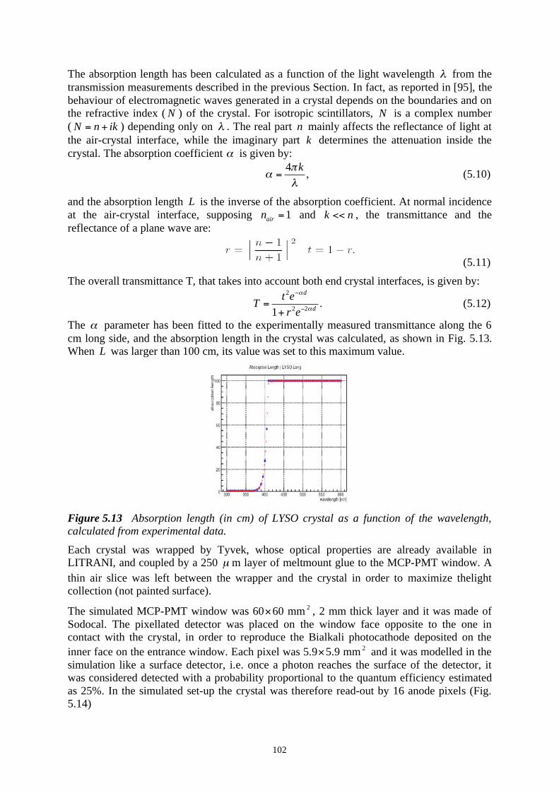
102
The absorption length has been calculated as a function of the light wavelength from the
transmission measurements described in the previous Section. In fact, as reported in [95], the
behaviour of electromagnetic waves generated in a crystal depends on the boundaries and on
the refractive index ( N ) of the crystal. For isotropic scintillators, N is a complex number
( N n ik= + ) depending only on . The real part n mainly affects the reflectance of light at
the air-crystal interface, while the imaginary part k determines the attenuation inside the
crystal. The absorption coefficient is given by:
4 k
= , (5.10)
and the absorption length L is the inverse of the absorption coefficient. At normal incidence
at the air-crystal interface, supposing 1air
n = and k n<< , the transmittance and the
reflectance of a plane wave are:
(5.11)
The overall transmittance T, that takes into account both end crystal interfaces, is given by:
2
2 21
d
d
t eT
r e= .
+ (5.12)
The parameter has been fitted to the experimentally measured transmittance along the 6
cm long side, and the absorption length in the crystal was calculated, as shown in Fig. 5.13.
When L was larger than 100 cm, its value was set to this maximum value.
Figure 5.13 Absorption length (in cm) of LYSO crystal as a function of the wavelength,
calculated from experimental data.
Each crystal was wrapped by Tyvek, whose optical properties are already available in
LITRANI, and coupled by a 250 μ m layer of meltmount glue to the MCP-PMT window. A
thin air slice was left between the wrapper and the crystal in order to maximize thelight
collection (not painted surface).
The simulated MCP-PMT window was 60 60 mm2
, 2 mm thick layer and it was made of
Sodocal. The pixellated detector was placed on the window face opposite to the one in
contact with the crystal, in order to reproduce the Bialkali photocathode deposited on the
inner face on the entrance window. Each pixel was 5.9 5.9 mm2
and it was modelled in the
simulation like a surface detector, i.e. once a photon reaches the surface of the detector, it
was considered detected with a probability proportional to the quantum efficiency estimated
as 25%. In the simulated set-up the crystal was therefore read-out by 16 anode pixels (Fig.
5.14)

103
Figure 5.14 Schematic drawing of the detector system simulated in LITRANI. The blue box
is the LYSO crystal located in the centre of the anode matrix (red squares) of the MCP-PMT.
The MCP-PMT window is delimited by the black line. The axis X and Y areindicated. The
perpendicular Z axis is such that Z=0 is far from the detector surface.
A number of photons equal to the measured LYSO light yield (when a 511 keV photon
produces a photoelectric effect) were isotropically generated inside the crystal, once given the
interaction point. The photons seen by the anode were considered detected if they reached the
pixel surface within 130 ns (integration time usually adopted in L(Y)SO based PET
scanners). The properties of the detected photons (arrival time, wavelength, distance traveled,
anode number) were recorded in ROOT format.
5.8 Performances simulated with LITRANI
Several position reconstruction methods are possible in continuous crystal read-out by
pixellated detectors and in the following the most important are briefly summarized
following the review by S. Tavernier 94
.
• Centre of gravity: a threshold is applied to the amplitude of the signal in each pixel,
and pixels below this threshold are not included in the calculation. The position of
interaction of the gamma is assumed to be the centre of gravity of the signal
amplitudes.
• Least squares: the response of the interaction at an unknown position is compared to a
set of reference events of known position. For each beam position the signal amplitude
of each pixel is calculated. To determine the X position, the signal of all pixels in Y
direction is integrated and the opposite for the Y determination. For each event of
unknown position, the difference in amplitude for each pixel with respect to reference
data sets is calculated. The position of the reference data that minimizes the difference
is assumed as the best estimate of the position of interaction.
• Chi-square: the method is very similar to the least squares one. For each beam
position, the signal amplitude of each pixel with an associated r.m.s. error is calculated.
Also in this technique the amplitude in X and Y are integrated. The difference between
the measured amplitude of the unknown position and the reference data sets of each
pixel are calculated, weighted with the error of the reference data. Also in this case the
interaction position is assumed to be the one that minimizes the 2 value.
94
Tavernier S. et al., "A high-resolution PET detector based on continuous scintillators", Nucl. Instr.
and Meth. A 537 (2005) 321-325.

104
The Depth Of Interaction (DOI) of the gamma in the crystal is related to the spread of signal
among pixels [96]. In fact, if the gamma interacts close to the detector surface, the light
would be shared among pixels very close to the (X,Y) interaction position. Instead, if the
gamma interacts far from the detector surface the number of involved pixels is larger.
Determination of the X coordinate of photoelectric events
In the previously described set-up, within the LYSO crystal, 2,000 events have been
generated with a scintillation point (0
X ,0
Y ,0
Z ) randomly chosen. With this data set the
spatial resolution in the two main directions X and Z, respectively parallel to 6 cm long side
and the 3 cm depth, has been first investigated.
Concerning the X direction, the signal on each pixel has been integrated in the Y direction,
for each scintillation position, summing the number of photoelectrons in the two Y-
contiguous pads. The centre of gravity CG
X of the obtained distributionwas is
pe i i
CG
pe i
N xX
N
,
,
= . (5.13)
It was expected that the reconstruction procedure applied would depend on the depth of
interaction 0
Z ranging between 0 cm (far) and 3 cm (close to the detector window).
Therefore, to perform the X-study, the simulated events were divided into three samples,
according to the depth of interaction: 0
Z smaller than 1 cm (first layer), within 1 cm and 2
cm (second layer) and between 2 cm and 3 cm (third layer) respectively.
According to [96], the reflection on the edges of the crystal influences the final achievable
spatial resolution. In order to investigate more deeply these border effects, a second
simulation was performed with the set-up identical to the previous one but with the two
12 30 mm2
end faces of the crystal painted in black so that each optical photon hitting one
of these two faces undergoes a total absorption. This was expected to at least reduce the
distortions of the X reconstruction due to the reflection on the borders, but with the
drawback of a loss of the photon collection efficiency (see Fig. 5.15). The total number of
events simulated was again 2,000 and they have been divided into three samples as
performed for the previous data set.
Figure 5.15 Ratio of the average number of optical photons seen by each anode in the two
simulation set-ups (Tyvek wrapping on all faces and Tyvek wrapping of 4 faces plus two end
faces black painted) as a function of 0
X . At the borders the overall light collection reduces
by about 60%.

105
Figure 5.16 The three panels show the sequence of the reconstruction procedure applied to
events generated in the third layer (i.e. between 2 cm and 3 cm, close to the detector surface)
of a black painted crystal. Left panel: the distribution of the coordinate 0
X of the real
position of the interaction as a function of a set of reconstructed position CG
X is calculated
and the shown average of their distributions is fitted by means of a polynomial function F
(red line). Middle panel: the average of the distribution of the differences between 0
X and
the expected real position ( )CG
F X for each set of values CG
X is computed and fitted by
means of a correcting function (red line). Right panel: the overall Monte Carlo spatial
resolution is obtained with a Gaussian fit of the distribution of the differences between 0
X
and the corrected expected position ( )CG
G X .
To each sample, the following procedure has been applied:
• the CG
X range was divided into bins, the distributions of 0
X for each value of CG
X
were averaged to obtain a set of data points 0
X< > and the pairs (CG
X ,0
X< > ) were
fitted in a restricted range by means of a polynomial function F (Fig. 5.16, left
panel);
• the distribution of 0 ( )CG
X F X< > as a function of CG
X was fitted by a polynomial
function mainly to correct the deviations of the reconstructed X from the real
position of interaction dominating at the edges of the crystal (Fig. 5.16, middle panel);
• the spatial resolution was computed from the r.m.s of the distribution of the
differences between 0
X and ( )CG
G X , where G is equal to F + (Fig. 5.16, right
panel).
The reconstructed position of interaction CG
X is well correlated to the true one in the central
region of the crystal. When 0
X is closer to the edges, the estimated centre of gravity is
distorted. In fact, since the anode pad finishes, the signal collected on one side of the
maximum is not balanced on the opposite side and moreover, in case of Tyvek wrapped
crystal, the reflection of the signal at the crystal borders increases the signal in far pixels. For
this reason the procedure of Fig. 5.16 was repeated for each layer of interaction.
The described reconstruction technique was applied to reconstruct events simulated in both
set-ups and the results are illustrated in Figs. 5.17 and 5.18.

106
Figure 5.17 Left panels: the profile of the average 0
X< > of the true coordinate of the
position of the interaction as a function of the reconstructed CG
X is fitted by a polynomial
function (red line). Right panel: the distribution of the deviations of all the 0
X from the
reconstructed position ( )CG
G X is shown. The analyzed events, simulated with a Tyvek
wrapped crystal, are divided into three samples according to their DOI: 0-1 cm (i.e. far from
the detector, top panels), 1-2 cm (middle panels) and 2-3 cm (i.e. close to the detector,
bottom panels).
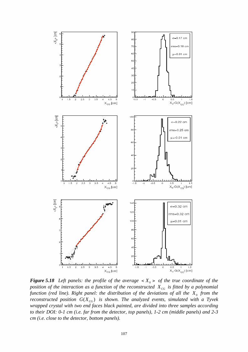
107
Figure 5.18 Left panels: the profile of the average 0
X< > of the true coordinate of the
position of the interaction as a function of the reconstructed CG
X is fitted by a polynomial
function (red line). Right panel: the distribution of the deviations of all the 0
X from the
reconstructed position ( )CG
G X is shown. The analyzed events, simulated with a Tyvek
wrapped crystal with two end faces black painted, are divided into three samples according
to their DOI: 0-1 cm (i.e. far from the detector, top panels), 1-2 cm (middle panels) and 2-3
cm (i.e. close to the detector, bottom panels).

108
It can be noted that the evolution of the distributions of the deviations between the real and
the reconstructed X is coherent in the two simulations. By increasing the depth of interaction
(i.e. coming closer to the detector pad) the well defined Gaussian distribution splits into two
components (Figs. 5.17 and 5.18 bottom panels): a narrow Gaussian distribution, to which
events in the central region of the crystal contribute, and a spread distribution due to events
close to the edges.
To estimate the evolution of the distribution with the depth of interaction three parameters
have been considered: the r.m.s, the FWHM and the FWTM of the full distribution. The first
is an indicator of the the quality of the full distribution and therefore is an estimate of the
spatial resolution. The FWHM estimates the properly reconstructed events in the central
region of the crystal and the FWTM takes into account the worsening of the spatial
distribution due to the tail. The results are shown in Table 15 where the efficiency, named ,
is the ratio between the number of events whose deviation is smaller than 5 mm and the total
number of events in eachsample. For each sample of events and for both simulations the
parameters are summarized in Table 5.4.
Table 5.4 Calculated values of r.m.s, FWHM, FWTM and for the totally reflective crystal
(refl.) and for the one with two black painted faces (black).
0Z [cm] r.m.s [mm] FWHM [mm] FWHM [mm] (
0 CGX X| |< 5 mm)
[%]
refl. black refl. black refl. black refl. black
0-1 cm 1 8. 1 8. 2 5. 4 0. 10 0. 8 0. 96 99
1-2 cm 1 9. 2 5. 3 0. 3 0. 9 0. 9 0. 93 98
2-3 cm 4 1. 3 2. 3 0. 1 8. 14 0. 10 2. 93 93
Firstly, it has to be remarked that all the obtained resolutions in the coordinate X fulfill the
requirement of an in-beam-PET. Secondly, it is interesting to note that with increasing depths
of interaction (i.e. getting close to the detector), the r.m.s becomes worst because of the non-
Gaussian form of the distribution. Thirdly the black painted crystal exhibits the best
performance in the last layer i.e. close to the detector surface. This improvement can be
explained by looking at Fig.5.15. When the interaction occurs close to the detector surface,
the absence of uncorrelated optical photons coming from reflections on the edges of the
crystal increases the linearity in the central region.
It has also to be noted that when a gamma interacts within a crystal, the probability of
interaction follows an exponential with the decay constant given by the attenuation length of
the scintillating material (e.g. 1.1 cm for LYSO). Therefore the number of photons interacting
in the first centimeter is larger than in the rest of the crystal. This underlines the importance
to achieve a fair spatial resolution in particular in the first layer, condition that the studied
device (at least from the simulation point of view) satisfies. In fact, looking at the efficiencies
reported in Table 15, almost all events are reconstructed with a deviation smaller than 5 mm
in the first two depth layers and only a small loss is present in the last one. From this point of
view, the black painted crystal seems to be preferable, also because the distributions of
Fig. 5.18 are more Gaussian (for 0
Z 2 cm) than the ones of Fig. 5.17.

109
Determination of the depth of interaction of photoelectric events
To determine the depth of interaction, appropriate indicators and their correlation with 0
Z
have been studied in detail.
The first estimator is the (named fit ) obtained from a Gaussian fit of the distribution of
the signal pe i
N, on the anode array. In fact it is expected that the closer is
0Z to the detector
surface the more peaked is the signal distribution. Hence the fit value is expected to
decrease with increasing depth of interaction. ALSO in this case the border effects are a
source of error in the reconstruction. In fact the signal distribution of events whose 0
X is
close to the crystal edges is flattened by photon reflections, resulting in an unreliable
correlation of fit with 0
Z .
By exploiting the good linear correlation existing between 0
X and the reconstructed CG
X ,
cuts were applied to study separately the reconstruction of Z in the central and in the lateral
region of the crystal. The events were divided into two samples: one with 2.2 CG
X< < 3.8 cm
and the other with CG
X 2.2 and CG
X 3.8 cm.
Figure 5.19 Events in the lateral region of the crystal: 2.2CG
X< < 3.8 cm. Top panels:
average 0
Z< > as a function of fit with the fitted curve superimposed (red line). Bottom
panels: distribution of the deviations between 0
Z and reco
Z , which is the position
reconstructed by means of the fit function illustrated in the top panels. The left panels refer to
Tyvek wrapped crystal while the right panels give the results for the crystal with two black
painted end faces.
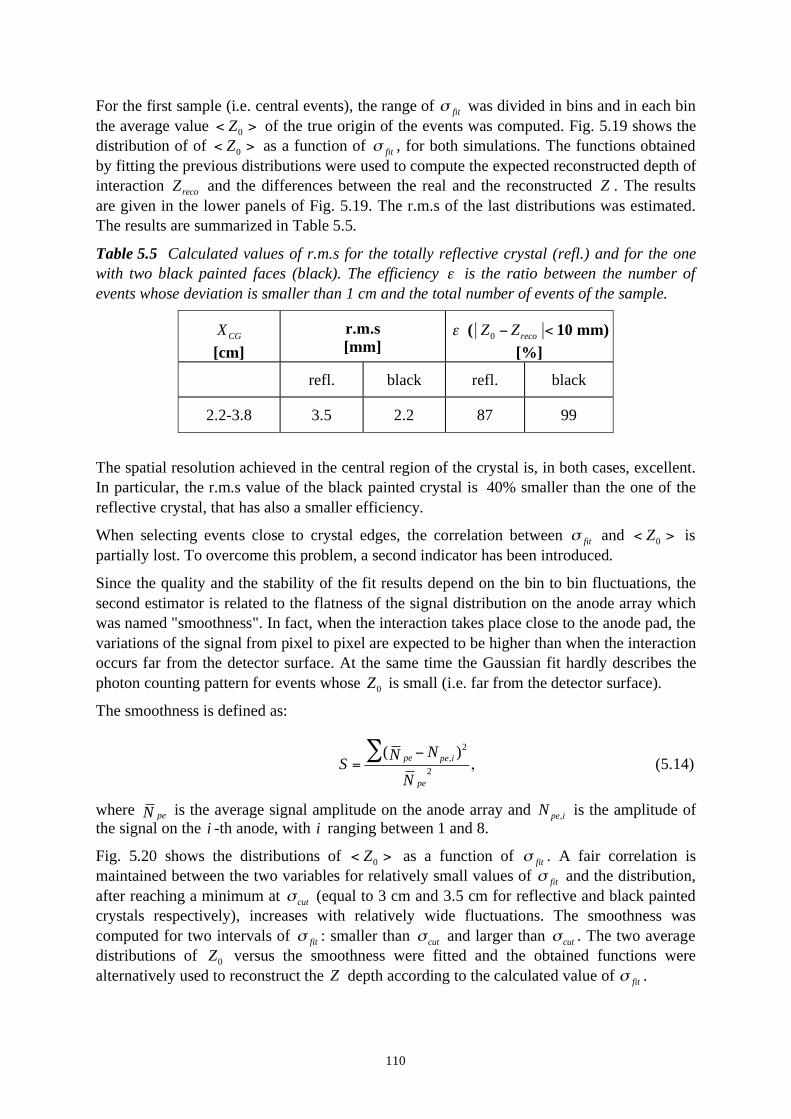
110
For the first sample (i.e. central events), the range of fit was divided in bins and in each bin
the average value 0
Z< > of the true origin of the events was computed. Fig. 5.19 shows the
distribution of of 0
Z< > as a function of fit , for both simulations. The functions obtained
by fitting the previous distributions were used to compute the expected reconstructed depth of
interaction reco
Z and the differences between the real and the reconstructed Z . The results
are given in the lower panels of Fig. 5.19. The r.m.s of the last distributions was estimated.
The results are summarized in Table 5.5.
Table 5.5 Calculated values of r.m.s for the totally reflective crystal (refl.) and for the one
with two black painted faces (black). The efficiency is the ratio between the number of
events whose deviation is smaller than 1 cm and the total number of events of the sample.
CGX
[cm]
r.m.s
[mm] (
0 recoZ Z| |< 10 mm)
[%]
refl. black refl. black
2.2-3.8 3.5 2.2 87 99
The spatial resolution achieved in the central region of the crystal is, in both cases, excellent.
In particular, the r.m.s value of the black painted crystal is 40% smaller than the one of the
reflective crystal, that has also a smaller efficiency.
When selecting events close to crystal edges, the correlation between fit and 0
Z< > is
partially lost. To overcome this problem, a second indicator has been introduced.
Since the quality and the stability of the fit results depend on the bin to bin fluctuations, the
second estimator is related to the flatness of the signal distribution on the anode array which
was named "smoothness". In fact, when the interaction takes place close to the anode pad, the
variations of the signal from pixel to pixel are expected to be higher than when the interaction
occurs far from the detector surface. At the same time the Gaussian fit hardly describes the
photon counting pattern for events whose 0
Z is small (i.e. far from the detector surface).
The smoothness is defined as:
2
2
( )pe pe i
pe
NNS
N
,= , (5.14)
where peN is the average signal amplitude on the anode array and pe i
N, is the amplitude of
the signal on the i -th anode, with i ranging between 1 and 8.
Fig. 5.20 shows the distributions of 0
Z< > as a function of fit . A fair correlation is
maintained between the two variables for relatively small values of fit and the distribution,
after reaching a minimum at cut
(equal to 3 cm and 3.5 cm for reflective and black painted
crystals respectively), increases with relatively wide fluctuations. The smoothness was
computed for two intervals of fit : smaller than cut
and larger than cut
. The two average
distributions of 0
Z versus the smoothness were fitted and the obtained functions were
alternatively used to reconstruct the Z depth according to the calculated value of fit .

111
Figure 5.20 The figure refers to events which are in the lateral region of the crystal:
CGX 2.2 cm and
CGX 3.8 cm. Left panels: distribution of
0Z< > as a function of fit .
Right panel: average distribution of the 0
Z as a function of the smoothness for FIT
< cut
(red points) and for fit cut> (blue points) with cut= 3.0 cm and 3.5 cm respectively. Top
panels refer to Tyvek wrapped crystal while bottom panels give the results for the crystal with
two end faces black painted.
The distribution of the deviations between the reconstructed and the real depth of interaction
are illustrated in Fig. 5.21.
Figure 5.21 Distribution of the deviations between the real and the reconstructed Z
coordinate for reflective crystal (left panel) and black painted crystal (right panel).
The estimated spatial resolutions summarized in Table 5.6

112
Table 5.6 Calculated values of r.m.s for the totally reflective crystal (refl.) and for the one
with two black painted faces (black). The efficiency is the ratio between the number of
events whose deviation is smaller than 1 cm and the total number of events of the sample.
CGX
[cm]
r.m.s
[mm] (
0 recoZ Z| |< 10 mm)
[%]
refl. black refl. black
0-2.2 and 3.8-6.0 5.3 5.7 83 93
The figures and the table show that the black painted crystal is superior in the measurement
of DOI both in the central and in the lateral regions. Moreover the two distributions are
nearly Gaussian in shape and their sigma values are not very different: 2.1 and 2.9 mm
respectively. By combining with the results obtained for the X coordinate, the black painted
crystal has to be preferred.
Summary of the Monte Carlo results on the spatial resolution
The spatial resolution, both in X and Z , obtained by applying the reconstruction techniques
described in the previous Section are within the limitations required for an in-beam-PET.
Both reflective and black painted crystals exhibit good performances but the black painted
crystal has to be preferred. On the whole crystal the average spatial resolution in the X
direction can be computed by combining the results summarized in Fig. 85 and taking into
account that, due to the 1.1 cm interaction length of 511 keV gammas in LYSO, the three
layers see 67%, 22% and 11% of the events. The overall distribution is shown in Fig. 5.22
and the overall resolution is 2.0 mm.
Figure 5.22 Left panel: distribution of the deviations between the true and the reconstructed
X coordinate for black painted crystal on the whole volume. The distribution is obtained by
weighting the distribution calculated for each layer by a factor proportional to the number of
511 keV gammas interacting at each depth. Right panel: distribution of the deviations
between the true and the reconstructed Z coordinate on the whole volume for the black
painted crystal.
Concerning the Z reconstruction, an excellent resolution is obtained in the central region of
the crystal, where the correlation between the signal distribution on the anode pad and the
interaction point is very pronounced. In this region, the spatial resolution is 2.2 mm,
practically equal to the X-resolution. Such a resolution is competitive with respect to the one
achieved by means of device optimized for DOI reconstruction. A degradation of the spatial
resolution is obtained when selecting events close to the crystal edges. In this region the

113
spatial resolution is 5.7 mm for the black painted crystal. The right panel of Fig. 5.22 shows
the distribution of the deviations between the true and the reconstructed Z coordinates,
averaged over the whole volume. The obtained overall spatial resolution is 3.4 mm. It has to
be noted that the worsening of the resolution close to the crystal edges is partially due to the
smaller active area of the detector with respect to the crystal length. Actually Burle is
working on a new MCP-PMT prototype having a higher active area that is expected to
improve the performance of the detector unit studied.
The techniques applied to reconstruct the X and Z coordinates are very sensitive to the bin
to bin fluctuations in the signal distribution on the pixel matrix, therefore it would be required
a very accurate calibration of the anode response in the experimental part.
It has to be underlined that one of the drawbacks of the studied device is foreseen to be the
poor Compton events resolution, as observed in Anger logic based device, but this issue
needs still to be investigated. In all circumstances Monte Carlo results are always more
favorable than experimental ones, but even if there would be in practice a loss in resolution
by a factor 2, the requirements of in-beam-PET would be satisfied.
5.9 Experimental results
Anode calibration
The gamma interaction point in a continuous crystal read-out configuration is obtained by
means of a reconstruction technique based on the interpolation and fit of the signal
distribution on the anode pad, as described in the previous Section. Even if the homogeneity
of the MCP-PMT from Burle is higher than the one of other photodetectors, the average level
of uniformity on the anode pad is quoted by the producer to be about 1:1.5, with a maximum
value of about 1:2.5. Such a difference would significantly affect the achievable accuracy in
the reconstruction of the interaction point within the crystal. Therefore at first a calibration of
the anode signal is recommended.
The monochromatic light used was a 3 mm diameter UV LED (LED3-UV-400-30) which
emits 400 nm photons (close to the maximum of the emission spectrum of LYSO). To focus
the light on the PMT window plane the LED was tucked into a plastic cylinder with an
appropriate hole and the holder was located in the eyepiece of a microscope (see Fig. 5.23).
The LED was powered with a 30 ns square pulse at 1 kHz.
Figure 5.23 Picture of the experimental set-up for the anode calibration of the MCP-PMT
anodes. In one of the eyepieces of the microscope a LED tucked into a plastic cylinder is
located and the 400 nm light emitted is focused on the PMT window plane.

114
The LED light was partially collimated by means of the plastic cylinder and focused on the
PMT window. The size of the spot was about 2 mm diameter.
The microscope was equipped with a mechanical support on which the MCP-PMT was fixed.
The PMT window could be moved in the microscope focusing plane and its position could be
arranged in both transversal directions ( X and Y ) with a precision of 0.3 mm.
The equipment was located in dark environment in order to suppress any backgrounds.
The electronic read-out chain used is schematically represented in Fig. 5.24.
Figure 5.24 Schematic drawing of the electronic read-out chain used in the anode
calibration measurement.
The MCP-PMT has one output giving the integrated signal over all anodes and a single read-
out for each anode. The MCP-PMT output was sent by a linear Fan Out (LeCroy 428F) to the
discriminator (LeCroy 821CL). A threshold is applied on the discriminator and the width of
the output NIM pulse set to 160 ns and fed to ADC (LeCroy 2249A) to trigger the acquisition
to the MCP-PMT output. The electronics was interfaced to the PC by a CAMAC Wiener CC-
USB. For each acquisition, 5000 events were recorded. For every anode and acquisition, the
pedestal was estimated and subtracted from the acquired signal.
The location of the read-out anodes with respect to the PMT window is represented in
Fig. 5.25.
Figure 5.25 Schematic drawing of the 8 8 anode matrix of the MCP-PMT from Burle. In
the red square the 16 read-out anodes are grouped.
Only the 16 anodes of interest were calibrated.

115
With the calibration setup we have measured the overall relative sensitivity of the MCP,
shown in Fig. 5.26. The red squares provide the maximum signal on each of 8 aligned anode
pads, while the black squares are the amplitude measured on the MCP output. One can see
that the maximum variation of the anode pad response is about 7%; this is not far from the
tolerance required for the position reconstruction, and can be corrected with a proper
calibration. Near the edge of the tube the amplitude drops, due to the geometry of the tube
and the finite size of the light spot used for the measurement.
Figure 5.26 Relative signal amplitude measured with a collimated UV light beam. Red
squares correspond to the amplitude measured in the centre of eight adjacent anode pads;
black squares correspond to the measured amplitude on the MCP output..
Even when the light spot was focused on the centre of an anode, a non negligible signal
(about 10 % of the reference anode) was measured in the neighbouring anodes. This signal
can arise from the non perfect collimation of the light spot as well as from optical photon
reflections within the PMT window and between the photocathode and the MCP surface. The
last contribution is a function of the angle of incidence of light on the PMT window.
LYSO crystal measurement
The Multi-Anode tube, shown in Fig. 5.27, was calibrated and then used in the measurements
described in this Subsection.
Figure 5.27The Multi-Anode Photomultiplier used for the measurements.
For the study of position and DOI localization according to the method discussed in the
previous section we have used the laboratory setup shown in Fig. 5.28.

116
Figure 5.28 Experimental setup for studying localization properties.
The main detector consists of a LYSO crystal, 60x12x30 mm3, mounted with the long side
perpendicular and in optical contact with the Multi-Anode Photomultiplier. The crystal was
Teflon wrapped and coupled through the 12 60 mm2
face (by means of Silicon grease) to
the MCP-PMT window in front of the 16 central read-outs. The crystal and the MCP-PMT
were placed on a metal support in order to maintain the crystal position fixed during all
measurements and to avoid any misalignment of the crystal with respect to the 16 anodes.
A smaller crystal, mounted on a standard Photomultiplier tube (PMT) allows to select events
corresponding to a 511 photon conversion. A lead collimator 5 cm thick with a 5 mm diameter
hole was located on the optical bench, with the 22Na source placed between the MCP and the
lead collimator. The distances between the collimator and the PMT and between the
collimator and the source were adjusted in order to obtain a ~2 mm diameter spot focused on
the LYSO crystal. The optical bench was adjusted in order to centre the gamma spot at
different distances with respect to the anode surface (i.e. at different Z).
The electronic chain used to perform all the measurements hereafter described is provided in
Fig. 5.29
Figure 5.29 Schematic drawing of the electronic read-out used to perform experimental
measurements.
The 12 mm thick crystal was positioned cantered between two anode pads rows, so that the
light flash generated by a gamma conversion was recorded on two rows of anodes. The 16
pads were connected via miniature cables to CAMAC-based multi-ADC modules95
; two
more channels were used to record the signals from the MCP and from the coincidence PMT.
Because of the rather long delay of the PMT, its signal could not be used directly for the
selection of coincidence two-gammas events; instead, we have used the MCP output to
95
LECROY Type 2249A 12-channels ADC

117
initiate the readout, and selected the events having a signal in the PMT within the energy
window corresponding to the 511 keV photopeak.
A LABVIEW-based system and a desktop PC were used for data acquisition and analysis.
Fig. 5.30 shows the pulse height spectra recorded on the MCP, for events in coincidence with
the PMT; the lower peak (green histogram) recorded on common MCP output, while the
higher distribution corresponds to the sum of pulse heights over 16 anodes, after correction
taking into account the response calibration. The energy resolution for the 511 keV
photopeak is 18.7%, adequate for position determination.
Fig. 5.30 Coincidence pulse height spectra on the MCP output (green) and sum of 16
anodes.
Measurements were performed for two values of DOI at 5 mm from the centre of the crystal:
Z=27 mm (close to the detector surface) and Z=2 mm (far from the detector surface); the
distributions of the signal amplitudes recorded for the two cases on the 16 anodes and
integrated in the Y dimension are shown in Fig. 5.31
Figure 5.31 Distribution of the signal on the anode pads far (left) and close (right) to the
detector surface. Top; measured distributions; bottom: simulated distributions in the same
conditions.

118
The measured distributions (Fig 5.31, top) are compared to the average distributions
computed by means of LITRANI with the (X, Z) coordinates of scintillation points set as the
experimental values (Fig. 5.31, bottom). When the DOI is far from the detector surface the
two distributions agree well, while in the second measurement the signal has a diffused
background.
Three processes that were not considered in the simulation and require further investigations
can explain the difference:
- Multiple energy depositions, causing a spread of the signal distribution on the anode pad;
this effect is expected to worsen the spatial resolution both in X and Z directions.
- Optical cross talk between anodes can further broaden the signal distribution.
- Difficulties encountered to properly model the optical materials in the simulation, in
particular the wrapping, can be an additional source of disagreement.
The localization accuracy for the different position of exposure has been estimated using a
simple center-of gravity calculation algorithm.
Fig. 5.32 provides the distribution of the reconstructed coordinate for a position near the
center of the crystal, both in the direction of its long face (X=40 mm) and in the DOI
direction (Z=19 mm). The distribution has a quasi-Gaussian shape, with 2.4 mm rms; the
small tail is probably due to the contribution of double-Compton events.
Figure 5.32 Distribution of the centre of gravity of the recorded signal profiles on anode
rows for an exposed region 40 mm from one edge of the crystal and 19 mm from the sensor.
Fig. 5.33 summarizes the measurements correlating the real coordinate of the collimated spot
and the one deduced by the centre-of gravity calculation.
Figure 5.33 Correlation between computed centre of gravity and real coordinate of the
exposed spot.

119
In the figure the error bars correspond to the standard deviation of the respective
distributions. One can see that, although the correlation is almost linear, the scale of the
reconstructed coordinates is compressed by the edge effects discussed previously. Taking
into account the finite size of the collimated photon source, the results indicate a localization
accuracy in the direction of the anode pad rows around 2 mm rms.
The localization accuracy along the direction perpendicular to the MCP (the DOI) has been
determined moving the collimated spot, at fixed X coordinate, in three positions 27, 18 and 5
mm from the top surface of the crystal (the entry face for the gammas). The Z coordinate is
then estimated, as discussed in the previous section, from the width of the detected
scintillation light distribution on the anode pads.
As shown in Fig. 5.34, the distribution is the narrowest for the largest DOI (27 mm,
corresponding to conversions 3 mm from the MCP readout), and spreads with asymmetric
tails for events far from the anodes.
Figure 5.34 RMS of the signal distribution on anode pad rows for three positions of the
collimated source.
Fig. 5.35 summarizes the results of the measurements, providing the correlation between real
DOI (Zdata) and average width of the distributions (< >). Error bars indicate the rms of the
width distributions.
Figure 5.35 Average width and error of the signal distribution for the three DOI positions.
As expected, the precision in the DOI determination depends on the penetration depth, and
permits to resolve events about 10 mm apart, corresponding to one third of the crystal
thickness.

120
5.10 Summary of the results and future work
The described simulation work and the preliminary experimental data obtained with a
reduced setup, confirm that proper analysis of the signal distribution on segmented light
sensors permits to reconstruct the coordinates of the conversion of 511 keV gammas in
crystals with a position accuracy around 2 mm rms in the plane perpendicular to the photon
direction, and a determination of the Depth of Interaction within the crystal with an accuracy
around 5 mm rms. An even coarse determination of the DOI permits the use of thicker and
more efficient crystals without suffering from parallax errors, an essential advantage for PET-
on-beam applications in view of the low activity and short lifetime of the positron-emitting
isotopes.
To continue investigating this promising approach to PET imaging, we are preparing an
improved setup:
- Two Multi-anode PM, of the model already used, will be procured and operated in
coincidence, thus largely increasing the event rates, presently limited by the small
sensitive area of the crystal-PMT used in coincidence;
- An electronic system is under development, making use of fast Analogue-to-Digital
Converters (ADC) directly mounted on the MCP sensors, and a dedicated read-out
interface to transfer the data to a desktop PC;
- The centre of gravity and distribution width reconstruction algorithms will be optimized,
combining experimental and simulation results, and implemented as on-line analysis of
the data; the aim is to obtain X-Y localization and DOI coordinates in real time.

121
6. IN-BEAM-PET WITH GAS DETECTORS
6.1 Introduction
While most commercial PET scanners make use of scintillating crystal detectors, the superior
localization properties and lower cost of gas-filled proportional counters have since long
attracted dedicated research. Able to amplify, detect and localize the charge released in the
gas by ionizing tracks, proportional counters have however a negligible efficiency in
detecting high-energy photons. However the efficiency can be enhanced with internal
converters, thin foils of high-Z materials used as electrodes or inserted in the gas volume.
Because of the requirement for the electron (Compton or photoelectric) produced in the
interaction to emerge from the converter into the gas, there is an optimum thickness for the
converter foil. For 511 keV photons and tungsten, this is typically around 100 m. To obtain
a reasonable efficiency, one needs several tens of converter foils in a stack of independent
detectors. A pioneering device of this kind was developed long ago at the Rutherford
Laboratory, assembling together twenty wire chambers planes with thin lead cathodes, each
with a two-dimensional electronic readout on thin cathode strips96
. A double arm detector had
typically 10% efficiency in coincidence and 3 mm resolution, and was successfully used for
years in clinical investigations97
.
In a more advanced device, the Heavy Drift Chamber, a composite converter is made of a
stack of metallic grids, alternating with insulators, with through holes; application of a graded
potential allows to drift the ionization electrons, resulting from the photon interaction in the
stack, to a single multi-wire proportional chamber for detection and localization98
. Named
HIDAC, the device has been extensively tested in hospital environment, and for years was
the highest accuracy PET scanner available99
.
Despite the lack of energy resolution, due to the partial absorption of the ejected electron in
the converter, these devices have good space resolution and low cost. However wire
chambers are difficult to manufacture and are rather fragile. More recent devices as RPC and
GEM are sturdier and present less mechanical problems. In this Chapter the applications of
such devices to PET systems are presented.
6.2 Optimization of the gamma detection efficiency in gas detectors
The optimization of the detection efficiency of 511 keV photons of gas detectors involves
several aspects. Many of these are peculiar to the gas detector considered. In the present
Section a detailed study of the optimization of a lead converter foil is carried out by means of
a pure Monte Carlo approach.
The Livermore Low Energy electromagnetic physics package of the Geant4 toolkit (see
Chapter 2) was used to simulate a point-like beam of 511 keV photons hitting
perpendicularly a thin slice of lead of 10 10 cm2
.
The 511 keV photons interact in the converter by photoelectric and Compton interactions.
Both result in the production of a lower energy electron that can ionize the gas gap and
96
Bateman J. E. et al, Nucl. Instr. and Meth. A176 (1980) 83. 97
Ott R. J. et al, Nucl. Instr. and Meth. A269 (1988) 436. 98
Jeavons A. et al, Nucl. Instr. and Meth. 124 (1975) 491. 99
Townsend D. et al, J.Nucl. Med, (1988)

122
consequently be detected by means of the multiplication of the freed electrons in the GEM
foil or in the RPC gap.
The probability that a 511 keV photon interacts in the converter increases with its thickness,
while - by increasing the thickness - the probability to extract a secondary electron (that is the
detectable particle) is lower. Therefore two efficiencies can be defined: one is given by the
fraction of primary gammas absorbed in the converter (abs, ) and the other is the electron
extraction probability from the converter (e ext, ). They can be expressed as following:
abs e ext
abs e ext
inc abs
N N
N N
, ,
, ,
, ,
= = , (6.1)
resulting in an overall efficiency given by:
e ext
abs e ext
inc
N
N
,
, ,
,
= = . (6.2)
In a single layer detector, the aim would be to maximize the number of produced electrons
over the number of incident primaries. When considering a multi-layer multi-converter
detector, it is necessary to evaluate the number of lost gammas (i.e. absorbed with no
consequent electron emission) per layer, since once an event is lost in a converter it cannot be
detected in any following layers. Moreover the converter thickness has to be chosen in order
to have reasonably high detection efficiency in a limited number of layers, to reduce the
radial depth of the tomograph (supposing to arrange the gas chambers on a cylindrical
geometry).
The present study is focused on transmitted electrons, i.e. forward directed with respect to the
incident gamma beam.
In case of GEM backscattered electrons, even if not negligible, do not contribute to the final
efficiency. In fact, secondary electrons freed in the gas gap above the converter foil by
backscattered electrons do not undergo any multiplication and are stopped by the converter
itself.
On the other hand, secondaries produced by backscattered electrons created by the interaction
of gammas in the GEM foil (Cu+Kapton) can undergo an avalanche in the same GEM were
they have been generated. Since the GEM foil does not attenuate a significant number of
gammas, this effect has been therefore neglected in the present study.
Considering multi-stack not independent RPCs (as discussed later) besides the contribution of
electrons directed in the forward direction, backscattered electrons can contribute as well to
the total efficiency. Since they are peculiar to a particular set-up they are not treated in detail
here.
The overall efficiency and the electron yield e ext, have been evaluated for different
thicknesses of the converter (Fig. 6.1). At rather low values of the thickness, the overall
efficiency curve exhibits a build-up region and reaches a plateau at high thicknesses. In fact,
by increasing the thickness a larger number of gammas interacts within the converter while a
smaller number of electrons exits the foil. This is clearer from the right panel of the figure.
For a thin converter e ext, approaches unity since the few gammas that interact yield
electrons capable to exit the converter, while for thick converter, for instance of 180 μ m, the
electron yield efficiency drops to 20%. Therefore from these distributions we deduce that the
optimum thickness of the lead converter is around 80 μ m.

123
Figure 6.1 Dependence of (left, black circles) and of the electron yield e ext, (right) as a
function of thickness of a single lead converter. In the left panel, the efficiency of
backscattered events (red squares) is also shown.
In Fig. 6.2 the overall efficiency as a function of the number of layers is plotted for two
selected thicknesses of lead: 50 μ m and 80 μ m. Up to 20 layers, the difference between the
two curves is rather small. At 50 layers (indicated in the figure by the black dashed line) is
about 20% and about 17% for the 50 μ m and 80 μ m thick slice respectively.
Figure 6.2 Dependence of the efficiency as a function of the number of lead converters
(spaced by 3 mm gas) for two different thicknesses: 50 μ m (black circles) and 80 μ m (red
squares).
Another factor that has to be considered is the energy resolution.
In standard PET applications the energy resolution has to be good enough to discriminate
against events arising from photons scattered within the object by rejecting those with low
measured energy. Gas detectors with internal converters have no energy resolution. It appears
however that a converter sheet has an efficiency decreasing with the photon energy, resulting
in a physical threshold for rejection of low energy photons.
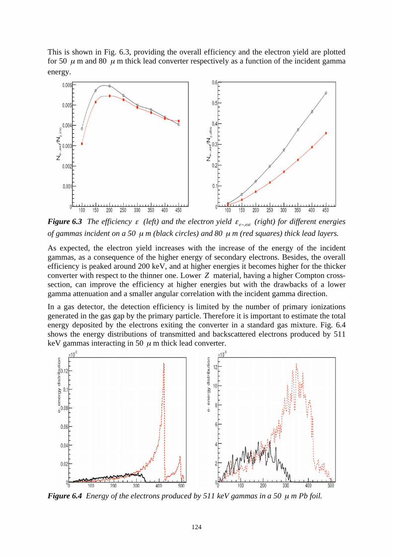
124
This is shown in Fig. 6.3, providing the overall efficiency and the electron yield are plotted
for 50 μ m and 80 μ m thick lead converter respectively as a function of the incident gamma
energy.
Figure 6.3 The efficiency (left) and the electron yield e ext, (right) for different energies
of gammas incident on a 50 μ m (black circles) and 80 μ m (red squares) thick lead layers.
As expected, the electron yield increases with the increase of the energy of the incident
gammas, as a consequence of the higher energy of secondary electrons. Besides, the overall
efficiency is peaked around 200 keV, and at higher energies it becomes higher for the thicker
converter with respect to the thinner one. Lower Z material, having a higher Compton cross-
section, can improve the efficiency at higher energies but with the drawbacks of a lower
gamma attenuation and a smaller angular correlation with the incident gamma direction.
In a gas detector, the detection efficiency is limited by the number of primary ionizations
generated in the gas gap by the primary particle. Therefore it is important to estimate the total
energy deposited by the electrons exiting the converter in a standard gas mixture. Fig. 6.4
shows the energy distributions of transmitted and backscattered electrons produced by 511
keV gammas interacting in 50 μ m thick lead converter.
Figure 6.4 Energy of the electrons produced by 511 keV gammas in a 50 μ m Pb foil.

125
The distributions plotted in the figure refer to transmitted (left panel) and backscattered (right
panel) electrons, produced by Compton (black solid line) and photoelectric (red dashed line)
interactions.
Electrons produced by Compton and photoelectric interactions are indicated with different
colors.
The maximum energy of a Compton electron from 511 keV is about 340 keV. In the
transmitted electron energy spectrum the shell structure of lead is clearly visible, with a
pronounced peak at about 400 keV corresponding to photoelectrons freed from the K-shell,
whose binding energy is 88 keV.
The total energy deposited by these photoelectrons in a 3 mm gas gap - filled with a Ar+CO2
(70%-30%) mixture - is shown in Fig. 6.5.
Figure 6.5 Total energy deposited per detected event in 3 mm gap filled with Ar 70% and
CO2
30%.
The total energy deposited was fitted by a Landau function, resulting in 0.71 keV mean
value. The mean energy deposit in Argon to produce an electron-ion pair is 26.3 eV,
therefore the average number of primary ionizations is about 27 (assuming a pure Argon gas).
This implies a practically 100%detection efficiency.
To estimate the achievale space resolution, the spatial distribution of the energy deposited in
the 3 mm Ar-CO2
was computed.
Fig. 6.6 shows that the energy is deposited in a cone around the primary beam direction - i.e.
perpendicular to the converter foil - with is less than two millimetres wide. This reflects the
fact that the secondary electrons are mainly produced in the forward direction.
The spatial distribution of the energy deposition projected in one of the transverse directions
has a low diffuse background with a sharp peak superimposed. The distribution was fitted by
the sum of two Gaussians of different widths. They are shown in the right panel of Fig. 6.6

126
.
Figure 6.6 Projected spatial distribution of the energy deposited by electrons in 3 mm gap
filled with a mixture Ar 70% and CO2
30%. In the left panel the distribution is projected on
the plane of the lead converter layer and in the right panel it is further projected in one
dimension.
The standard deviation of the sharper Gaussian is of particular interest since it is a direct
estimation of the difference between the reconstructed position of interaction of the gamma
(i.e. exploiting the signal distribution on the read-out plane) and the real interaction point of
the gamma in the converter layer since all gammas hit the converter in (x,y)=(0,0). The
calculated deviation is 80 μ m.
By taking into account all the factors discussed above, as an optimum a 50 μ m lead
converter has been chosen to perform first experimental estimations of the detection
efficiency of 511 keV gammas emitted by a 22
Na source.
A simple set-up consisting of the lead converter and a standard GEM foil, with 3 mm gas gap
(Ar-CO2
) has been designed and built. The events will be acquired in coincidence with a
standard PMT-crystal detector. The measured efficiency will be the overall detection
efficiency, i.e. including gamma absorption, electron extraction and gas ionization by the
extracted electron.
6.3 Resistive Plate Chambers (RPC)
A new line of search has appeared based on the use of a sturdier device, the Parallel Plate
Avalanche Chamber sometimes called simply PPC (Parallel Plate Chamber). Constituted by
two conducting electrodes separated by a thin gas layer, PPACs are cheap, robust and simple
to build.
In the present proposal, the major drawback of conventional parallel plate counters, the
tendency to discharge when operated at large gains, is solved making one or both electrodes
with a high-resistivity material, having the property of quenching discharges by a local
voltage drop. Using high-resistivity glass as electrodes, high gas pressures and narrow gaps
(100 m or less) to reduce the statistical fluctuations in the avalanche formation, the so-called
Pestov or spark counters can achieve few tens of ps time resolutions100
, a very attractive
feature for PET systems.
100
Pestov Yu., Nucl. Instr. and Meth. 196 (1982) 45.

127
In a popular model, with Bakelite electrodes, wide gaps operated at atmospheric pressures
Resistive Plate Chambers (RPC)101
have mm localization properties and time resolutions of a
few ns, and are widely used in particle physics to cover large detection areas102
.
More performing RPCs, in particular for what concerns the timing properties without the
need of using inconveniently high gas pressures, have been recently developed. The
statistical dispersion intrinsic in the energy loss process is reduced by the use of narrow gaps,
and, to compensate for the low efficiency, multi-gap structures are assembled in the same
detector, with signals or-ed together as shown in Fig. 6.7103
.
Figure 6.7 Thin-gap RPCs or-ed together for fast response and good efficiency.
Alternatively, a composite detector can be made with a stack of independent RPCs104
(Fig. 6.8). To reduce the complexity of the electronics, the position information can be
obtained not individually in each layer, but from a hardware wiring in columns of the readout
electrodes. A fast pulse, recorded from an electrode in each layer, provides the timing and
DOI information.
Figure 6.8 A stack of 6 independent RPC gaps with internal conversion layers; readout
strips in each layer are connected in columns to reduce the complexity of the electronics.
An elegant way to achieve the best timing properties of narrow gaps, preserving efficiency
without the need of readout electronics on each gap, is to assembly in the same detector,
between two active electrodes, several thin insulating electrodes (usually made of glass), left
floating, get the appropriate potential by electrostatic equilibrium105
as shown in Fig. 6.9.
Used in CERN’s ALICE detector, Multigap RPCs can achieve full efficiency for minimum
ionizing tracks with 50 ps time resolution and are used to identify particles from a
measurement of Time of Flight 106
.
101
Cardarelli R. et al, Nucl. Instr. and Meth. 333 (1993) 399. 102
Proc. Int. Workshop on Resistive Plate Chambers, Nucl. Instr. and Meth. A533 (2004) 103
Blanco A. et al, Nucl. Instr. and Meth. A533 (2004) 139. 104
Anulli F. et al, A Hybrid Parallel Plate gas Counter for Medical Imaging, Proceedings of the
International Symposium On Detector Development For Particle, Astroparticle and Synchrotron
Radiation Experiments (SNIC 2006), SLAC, April 2006, in print. 105
Cerron Zeballos E. et al, Nucl. Instr. and Meth. 374 (1996) 132. 106
Akindinov A. N. et al, Nucl. Instr. and Meth. A533 (2004) 74.

128
Figure 6.9 Schematics of the Multi-Gap RPC. The operating voltage is applied between the
outer cathodes and the central anode; intermediate resistive electrodes obtain the
appropriate voltage by electrostatic equilibrium.
The described detectors, when used in a PET device, provide mm position information,
correction of the parallax error and sub-ns time resolution. Despite their performances,
however, the described RPC devices have a drawback for the use as detectors of high energy
photons: most high-Z materials, needed to improve the conversion efficiency, are metallic,
and therefore can at best be used for one electrode, the second being a high-resistivity
material. This implies that in a multi-stack device each layer has to be read-out individually,
with a heavy electronic overhead. Use of floating lead-glass glass plates both as converters
and floating electrodes with the Multigap geometry permits to increase the efficiency of a
stack with a single readout plane; this is the solution proposed by the authors of Ref. 19. A
recent Monte Carlo simulation by the group shows than using borosilicate or lead-loaded
glass one can reach 30-40% detection efficiency for 500 keV photons with a stack of 50
plates, 300 m thick each for borosilicate glass and 100 m for lead glass (Fig. 6.10)107
.
Based on experience acquired during the development of Micro-Strip Chambers
manufactured on thin glass substrates, however, doubts can be raised on the stability of such
a detector at high radiation fluxes. Boro-silicate glass can be procured with the required
thickness and high resistivity (1010
-1011
cm-3
), but its electrical properties depend on the
migration of ions, inevitably resulting in long-term polarization, modifying electrical
characteristics108
. Glass with electronic conductivity exists, and was in fact used in the
original Pestov Counters, but it is very expensive and not available in large sizes.
For CNAO a better solution is proposed which is based on the work done on Micro-strip
chambers. A thin controlled-resistivity diamond-like layer is deposited on glass by Carbon
Vapor Deposition, appropriate to avoid charging up and polarization problems can be easily
obtained by a standard low cost industrial method109
. Fig. 6.11 shows several glass converter
plates stacked with a common electronic readout on each side of the stack. For the converters,
a borosilicate floated glass available in large sizes and 300 m thickness, will be used110. 111
.
107
Fonte P., Nucl. Instr. and Meth. A580 (2007) 915. 108
Alunni L. et al, Nucl. Instr. and Meth. A348 (1994) 344. 109
Bouclier R. et al, Nucl. Instr. and Meth. A369 (1996) 328. 110
DESAG D-263, made by Deutsche Spezialglas AG, Griinenplan. 111
SURMET Co, Burlington MA, USA.

129
Figure 6.10 Computed efficiency of a multi-gap RPC for 511 keV photons as a function of
plate thickness and number, for borosilicate glass (left) and lead-glass (right).
Figure 6.11 Multi-gap RPC with the internal floating electrodes made of glass with high-
resistivity coating, for improved stability of operation.
In the figure, five floating electrodes are assembled in a single detector, with 100 m gaps;
thin insulating rods help preserving the gap thickness. In the floating electrode configuration
of the Multigap RPC, only the two outer electrodes are powered, the other plates setting at
the equilibrium value of voltage. However, having well defined high-resistivity electrodes, a
more stable operation, particularly at high radiation rates, would be to apply the appropriate
potential to each electrode through a simple resistor chain, connected to ground and HV at
the two ends.
An artist's view of a module assembly, currently on design by TERA is shown in Fig. 6.12
and 6.13. The converter electrodes, resistive-coated glass plates, 300 m thick, are inserted in
grooves cut in two thin ceramic plates (Fig. 6.6); a front and a back plate then close the
structure; the topmost glass sheet is covered by a conductive layer (graphite) and connected
to the high voltage; similarly, on the bottom side, the two-dimensional strip readout circuit is
placed in contact but mechanically independent to the lower face of the first glass plate at

130
ground potential (Fig. 6.7). For the preliminary tests, the module will be assembled without
the front and back ceramic plates, and mounted inside a gas envelope; future plans however
call for a sealed assembly, filled during manufacturing with the preferred gas mixture.
Fig. 6.12 Five glass foil module assembly between grooved ceramic plates.
Fig. 6.13 A complete module with top HV connection and bottom 2-D readout circuit.
Depending on the detector geometry and photon angular range, the number of plates within
one module can be increased, reducing the cost of the readout. To reach the desired
efficiency, several modules have to be stacked as in Fig. 6.14.
Figure 6.14 Schematic representation of a PET system using two possible assemblies of
RPC modules, partly overlapping.
The figure shows a possible assembly scheme of a full ring PET scanner making use of the
described RPC detectors: individual modules have a size of 10 cm radially and are 30 cm
long. To avoid the efficiency loss at the edges, the modules can be assembled alternatively at
a different radius, or slightly rotated with a partial overlap as shown in the figures.

131
6.4 Gas Electron Multiplier (GEM)
Owing to their excellent position resolution and high rate capability, Gas Electron Multiplier
(GEM) detectors are widely used for tracking of charged particles in high-energy physics112
.
Applications in other fields have also been developed, in particular for neutron and high-
energy X-ray detection, adding appropriate converter sheets in front of the GEM electrodes
used for charge amplification; thicker electrodes on the multipliers themselves can act as
converters. To compensate for the low efficiency of a single element, multi-layer structures
are made, with stacks of converter-GEM pairs; ionization released by a photon conversion
anywhere in the stack is transported through the structure into a terminal position-sensitive
GEM detector.
A fundamental problem hinders however the use of the technology, when its performances
are confronted to crystal-based detectors. In a multi-layer GEM-converted stack, one has to
ensure that the amount charge transported to the final multiplier does not depend on the
conversion depth; this implies that each layer has to have unitary effective gain. The
thickness of each layer, typically several mm, adds then an (unknown) delay to the final
charge collection, implying a poor time resolution; for ten layers, this is of several hundred
ns, seriously restricting the use of the device. For thick detectors and off-normal angles of
incidence of the photons, there is also a large parallax error in the coordinate determination.
In collaboration with the Gas Detectors Development group at CERN we have studied a
structure that permits to overcome this limitation113
. The basic concept is to design each
element in a multi-layer GEM-converter stack with high gain, to allow local detection of the
event, but very low charge transmission to the following elements; if G is the effective gain
of a foil, the goal of unitary gain for each layer is achieved if its the transmission is 1/G. We
demonstrated that this can be obtained using a converter foil with narrow holes and optimized
values of electric fields with the single-cell prototype detector shown in Fig. 6.15:
Fig. 6.15 Single-cell GEM-converter prototype.
Charge released in the drift space by a source is injected into GEM1 and amplified; choice of
a high field EH followed by a low optical transparency mesh and a low field EL allow to
collect most of the avalanche charge on the mesh, with only a small transfer into the
following cell.
We recorded the charge on the mesh and on the anode as a function of GEM voltages and
electric fields above and below the mesh (EH and EL respectively); a summary of the results
is shown in Fig. 6.16, giving the ratio of mesh and anode charge as a function of GEM
effective gain, for two choices of fields. Owing to the different charge collection efficiency,
the unitary ratio is reached at different gains.
112
Sauli F., Nucl. Instr. and Meth. A522 (2004) 93. 113
Croci G., Ropelewski L., Sauli F. and Solevi P., "Depth of interaction determination in GEM-
based multi-layer PET detectors", Nucl. Instr. and Meth. A582 (2007) 693.
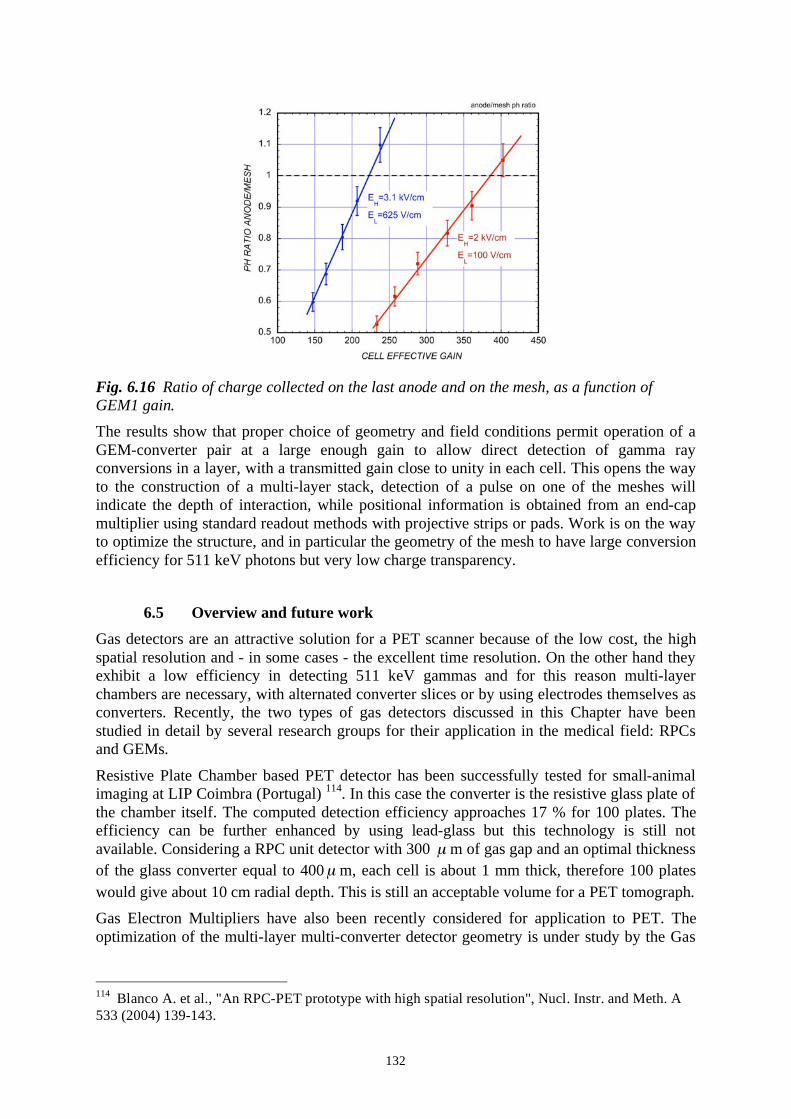
132
Fig. 6.16 Ratio of charge collected on the last anode and on the mesh, as a function of
GEM1 gain.
The results show that proper choice of geometry and field conditions permit operation of a
GEM-converter pair at a large enough gain to allow direct detection of gamma ray
conversions in a layer, with a transmitted gain close to unity in each cell. This opens the way
to the construction of a multi-layer stack, detection of a pulse on one of the meshes will
indicate the depth of interaction, while positional information is obtained from an end-cap
multiplier using standard readout methods with projective strips or pads. Work is on the way
to optimize the structure, and in particular the geometry of the mesh to have large conversion
efficiency for 511 keV photons but very low charge transparency.
6.5 Overview and future work
Gas detectors are an attractive solution for a PET scanner because of the low cost, the high
spatial resolution and - in some cases - the excellent time resolution. On the other hand they
exhibit a low efficiency in detecting 511 keV gammas and for this reason multi-layer
chambers are necessary, with alternated converter slices or by using electrodes themselves as
converters. Recently, the two types of gas detectors discussed in this Chapter have been
studied in detail by several research groups for their application in the medical field: RPCs
and GEMs.
Resistive Plate Chamber based PET detector has been successfully tested for small-animal
imaging at LIP Coimbra (Portugal) 114
. In this case the converter is the resistive glass plate of
the chamber itself. The computed detection efficiency approaches 17 % for 100 plates. The
efficiency can be further enhanced by using lead-glass but this technology is still not
available. Considering a RPC unit detector with 300 μ m of gas gap and an optimal thickness
of the glass converter equal to 400μ m, each cell is about 1 mm thick, therefore 100 plates
would give about 10 cm radial depth. This is still an acceptable volume for a PET tomograph.
Gas Electron Multipliers have also been recently considered for application to PET. The
optimization of the multi-layer multi-converter detector geometry is under study by the Gas
114
Blanco A. et al., "An RPC-PET prototype with high spatial resolution", Nucl. Instr. and Meth. A
533 (2004) 139-143.

133
Detector Group at CERN 115
. Such a geometry has been chosen in order to control the cost of
the full device, dominated by the electronic required that increases with the number of layers.
According to the study described in this Chapter, a lead converter with thickness ranging
between 50 and 80 μ m is required and an experimental measurement of the detection
efficiency of a 50 μ m lead converter combined with a GEM foil with 3 mm gas gap is in
progress.
These technologies show some differences that need a more detailed discussion.
The final total efficiency of a GEM based device for a 511 keV photon detection has to take
into account the probability that an electron produced by the gamma interaction in the
converter creates a certain number of primary ionizations (p
N ). The lower is the energy of
the exiting electrons the higher is p
N , that depends on the gas gap thickness as well. In case
of RPCs, working at higher applied field, an electron that produces a few ionizations in the
"effective" gap (generally the first half of the gas gap) is detected. This component of the
detection efficiency limits the thickness of the gas gap in GEM chambers, which cannot
therefore be too small. Hence, a GEM based detector would be thicker than a RPC based one
by a factor three.
Moreover, in in-beam-PET applications, were the rate is low, the detection efficiency is
important because determines the sensitivity of the scanner. The sensitivity is determined by
other components as the geometrical coverage of the tomograph. With the lower cost of gas
detectors, large volumes can be easily fabricated.
Another important factor is the sensitivity possible with a good measurement of the Time Of
Flight (TOF). A good time resolution makes possible to confine the source position in the
FOV of the scanner by measuring the difference of the arrival times of the two events
detected in coincidence. The sensitivity gain is given by the formula:
2
( 2)TOF
dg
t c= ,
/
where d is the average radius of the scanned object, t the time resolution and c the speed
of light. By assuming d =5 cm and t=300 ps, the gain is about 2 for RPCs. For a GEM
based detector, due to the lower timing performance, there is no gain in using the TOF
information.
It is clear that, even if converter materials with higher efficiency would be found, the
geometrical occupancy of a gas detector based scanner will be higher than the one based on
crystals. The lower sensitivity can be compensated by increasing the geometrical coverage of
the scanner that, on the other hand, would complicate the location of a large device with
respect to the patient and the other components of the treatment system.
In conclusion, for the smaller size and the higher timing performance, RPCs are a more
attractive solution with respect to GEMs. A first prototype for human RPC PET is at present
under production at the University LIP of Coimbra and will be ready and tested by the end of
2007. It is a 30 30 cm2
head, which assures 3D measurement of the interaction point. A
similar development is being planned by the TERA Foundation, so to have a definite device
to compare, in performances and cost, with the crystal solution discussed in the previous
Chapter.
115
Croci G., Ropelewski L., Sauli F. and Solevi P., "Depth of interaction determination in GEM-
based multi-layer PET detectors", Nucl. Instr. and Meth. A582 (2007) 693.

134