Embed Size (px)
Citation preview
SIRIUS RELAYS
Siemens Canada Limited Industrial Control Product Catalog 2019 12/1
12
RELAYS, IN
TERFACES
& CO
NVERTERS
Siemens / Industrial Controls Previous folio: 11/1
c o n t e n t sSection Overview 12/2 - 12/3
Temperature Monitoring RelaysOverview 12/4Selection, 3RS10-11, 3RS20-21 Analog with One Threshold Value 12/5 Analog with Two Threshold Values 12/5 Digital with Two Threshold Values 12/6Technical Data 12/7Configuration 12/8Functions 12/9Circuit Diagrams 12/10Dimensions 12/11
Thermistor Motor ProtectionOverview 12/12Benefits and Application 12/13Technical Specifications 12/14 - 12/15Function Diagrams 12/16Technical Data 12/17 - 12/183RN2 Selection and Ordering Data 12/19Accessories 12/20
Timing Relays General Data 12/21 3RP25 Timing Relays, 17.5 mm and 22.5 mm Overview 12/22 - 12/23 Technical Data 12/25 Circuit Diagrams 12/26 - 12/30 Functions 12/31 - 12/36 Selection and Ordering Data 12/37 Accessories 12/383RP20 Timing Relays, 45mm Overview 12/39 Technical Data 12/40 Functions 12/41 12/42 Selection and Ordering Data 12/43 Accessories 12/447PV15 Timing Relays, 17.5mm Overview 12/45 Technical Data 12/46 Circuit Diagrams 12/46 - 12/47 Functions 12/48 - 12/49 Selection and Ordering Data 12/50
Monitoring Relays for Stand-alone Installation General data 12/51 Line monitoring 12/53 Voltage monitoring 12/58 Current monitoring 12/61 Power factor and active current monitoring 12/63Residual-current monitoring Residual-current monitoring relays 12/66 3UL23 residual-current transformers 12/68Insulation monitoring General data 12/69 For ungrounded AC networks 12/71 For ungrounded DC and AC networks 12/73
Level monitoring Level monitoring relays 12/76 Level monitoring sensors 12/79Speed monitoring 12/80Accessories 12/83
Monitoring Relays For Stand-alone Installation for IO-Link General data 12/84 Line monitoring 12/87 Voltage monitoring 12/90 Current monitoring 12/93 Power factor and active current monitoring 12/96Residual-current monitoring Residual-current monitoring relays 12/100Speed monitoring 12/103Accessories 12/106
Coupling Relays and Interfaces3RQ3 Overview 12/107Benefits 12/108Technical Data 12/109 - 12/110Circuit Diagrams 12/111Selection and Ordering 12/112 - 12/114Accessories 12/115
Wide Input Interface RelayOverview 12/116Selection, 3RS18 12/116Dimensions 12/116
Interface Converters3RS70 Overview 12/117Technical Data 12/118 - 12/120Circuit Diagrams 12/121Selection and Ordering 12/122Accessories 12/123
Power RelaysOverview 12/125Selection, 3TG10 12/125Technical Data 12/126 - 12/127Accessories 12/128Circuit Diagrams 12/128Dimensions 12/128
Plug-in RelaysSelection, 3TX71 12/129 - 12/132Technical Data 12/133 - 12/134Overview 12/135Circuit Diagrams 12/136 - 12/138Dimensions 12/139 - 12/145
Function Relays, Interfaces and Converters Industrial Controls Product Catalog 2019 Section
SIRIUS RELAYS
Siemens Canada Limited Industrial Control Product Catalog 201912/2
12
RELA
YS, I
NTE
RFA
CES
& C
ON
VERT
ERS
Siemens / Industrial Controls Previous folio: 11/2
c o n t e n t s
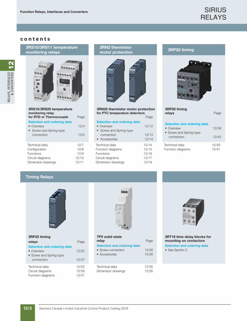
3RS10/3RS11 temperature monitoring relays
3RN2 thermistor motor protection
3RP20 timing
3RS10/3RS20 temperaturemonitoring relayfor RTD or Thermocouple Page
Selection and ordering data• Overview 12/4• Screw and Spring-type connection 12/5
3RN20 thermistor motor protectionfor PTC temperature detectors Page
Selection and ordering data• Overview 12/12• Screw and Spring-type connection 12/13• Accessories 12/14
3RP20 timingrelays Page
Selection and ordering data• Overview 12/39• Screw and Spring-type connection 12/43
Technical data 12/7Configuration 12/8Functions 12/9Circuit diagrams 12/10Dimension drawings 12/11
Technical data 12/14Function diagrams 12/15Functions 12/16Circuit diagrams 12/17 Dimension drawings 12/19
Technical data 12/40Function diagrams 12/41
Timing Relays
3RP25 timingrelays Page
Selection and ordering data• Overview 12/22• Screw and Spring-type connection 12/37
7PV solid-staterelay Page
Selection and ordering data• Screw connection 12/26• Accessories 12/26
3RT19 time delay blocks formounting on contactors
Selection and ordering data• See Section 2
Technical data 12/25Circuit diagrams 12/26Function diagrams 12/31
Technical data 12/26Dimension drawings 12/26
Function Relays, Interfaces and Converters
SIRIUS RELAYS
Siemens Canada Limited Industrial Control Product Catalog 2019 12/3
12
RELAYS, IN
TERFACES
& CO
NVERTERS
Siemens / Industrial Controls Previous folio: 11/3
c o n t e n t s
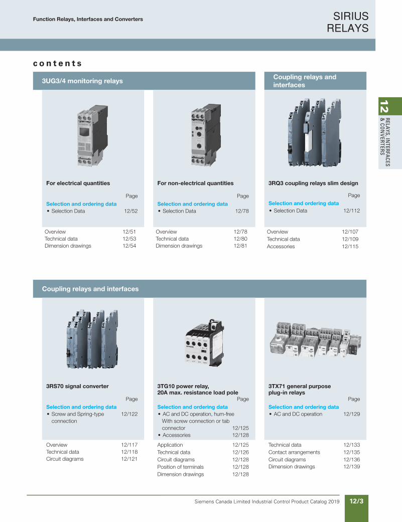
3UG3/4 monitoring relaysCoupling relays and interfaces
For electrical quantities Page
Selection and ordering data• Selection Data 12/52
For non-electrical quantities Page
Selection and ordering data• Selection Data 12/78
3RQ3 coupling relays slim design
Page
Selection and ordering data• Selection Data 12/112
Overview 12/51Technical data 12/53Dimension drawings 12/54
Overview 12/78Technical data 12/80 Dimension drawings 12/81
Overview 12/107Technical data 12/109Accessories 12/115
Coupling relays and interfaces
3RS70 signal converter Page
Selection and ordering data• Screw and Spring-type 12/122 connection
3TG10 power relay,20A max. resistance load pole Page
Selection and ordering data• AC and DC operation, hum-free With screw connection or tab connector 12/125• Accessories 12/128
3TX71 general purposeplug-in relays Page
Selection and ordering data• AC and DC operation 12/129
Overview 12/117Technical data 12/118Circuit diagrams 12/121
Application 12/125 Technical data 12/126Circuit diagrams 12/128Position of terminals 12/128Dimension drawings 12/128
Technical data 12/133Contact arrangements 12/135 Circuit diagrams 12/136 Dimension drawings 12/139
Function Relays, Interfaces and Converters
SIRIUS RELAYS
Siemens Canada Limited Industrial Control Product Catalog 201912/4
12
RELA
YS, I
NTE
RFA
CES
& C
ON
VERT
ERS
Siemens / Industrial Controls Previous folio: IC10 11/4
Overview
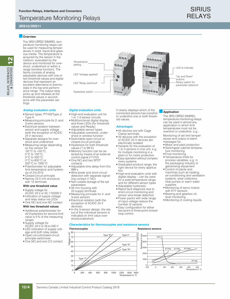
The 3RS1/3RS2 SIMIREL tem-perature monitoring relays can be used for measuring temper-atures in solid, liquid and gase-ous media. The temperature is acquired by the sensor in the medium, evaluated by the device and monitored for over-shoot, undershoot or within a range (window function). The family consists of analog adjustable devices with one or two threshold values and digital devices that represent an excellent alternative to thermo-stats in the low-end perform-ance range. The output relay picks up and releases at the threshold values in accord-ance with the parameter set-tings.
Analog evaluation units• Sensor types: PT100/Type J/
Type K• Measuring principle for 2- and
3-wire sensors• Electrical isolation between
sensor and supply voltage (with the exception of AC/DC 24 V devices)
• Separate designs for over-shoot and undershoot
• Measuring range depending on the version for -50 °C to +50 °C,0 °C to 100 °C, 0 °C to 200 °C, 0 °C to 600 °C or 500 °C to 1000 °C
• Potentiometer for adjustable limit temperature and hystere-sis of 2 to 20%
• Closed-circuit principle• Narrow 22.5 mm enclosure
with 12 terminalsWith one threshold value• Supply voltage for
AC/DC 24 V or AC 110/230 V• Indication of supply voltage
and relay status via LEDs• One NO and one NC contactWith two threshold values • Additional potentiometer for ϑ2 (hysteresis for second limit value is 5 % of the measuring range)
• Supply voltage for AC/DC 24 V or 24 to 240 V
• LED indication of supply volt-age and both relay states
• Open-circuit/closed-circuit principle switchover
• One NO and one CO contact
Digital evaluation units • High-end evaluation unit for
1 or 1-3 sensor circuits• Multifunctional digital display
and three LEDs (for threshold values and Ready)
• Adjustable sensor types • Adjustable overshoot, under-
shoot or window function• Switchable open-circuit or
closed-circuit principle• Hysteresis for both threshold
values (1 to 99 K)• Memory function can be se-
lected by means of an external control signal (Y1/Y2)
• One NO and two SPDT contacts
• Adjustable time delay from 0 to999 s
• Wire-break and short-circuitdetection with separate signal-ling contact (1 NO)
• Non-volatile storage of the set parameters
• 45 mm housing with 24 supply terminals
• Measuring principle for 2- and 3-wire sensors
• Electrical isolation (with the exception of AC/DC 24 V devices)
• In the 3-sensor design, the sta-tus of the individual sensors is indicated on limit value over-shoot/undershoot
It clearly displays which of the connected sensors has overshot or undershot one or both thresh-old values.
Advantages• All devices are with Cage
Clamp terminals• All devices with the exception
of AC/DC 24 V devices are electrically isolated
• Variants for the evaluation of 1 to 3 sensors in one unit, e.g. for multiple monitoring in a plant or for motor protection
• Easy operation without complex menu systems
• Graduated product range; the right device for every applica-tion
• High-end evaluation units with digital display – can be used for a wide temperature range and for different sensor types
• Adjustable hysteresis• Rapid fault diagnosis due to
short-circuit monitoring and sensor wire-break detection
• Power packs with wide range of input voltage reduce the number of variants
• Easy configuration for either two-point or three-point closed-loop control
ApplicationThe 3RS1/3RS2 SIMIREL temperature monitoring relays can be used in almost any application in which limit temperatures must not be overshot or undershot, e.g.:Monitoring of set limit temper-atures and output of alarm messages for:• Motor and plant protection• Switchgear cabinet tempera-
ture monitoring• Frost monitoring• Temperature limits for
process variables, e.g. in the packaging industry or galvanising equipment
• Control of plants and machines such as heating, air-conditioning and ventilation systems, solar collectors, heat pumps or warm water supplies
• Monitoring of servo motors with KTY sensors
• Bearing and gearbox oil-level monitoring
• Monitoring of cooling liquids
Characteristics for thermocouples and resistance sensors
LED to indicate
"Up and Down" buttonsRotary switch for parameter selection
Temperaturesetting
LED "Voltage applied"
LED "Relay switched"
Hysteresis switch
srosnes ecnatsiseRselpuocomrehT
Function Relays, Interfaces and Converters
Temperature Monitoring Relays3RS10/3RS11
SIRIUS RELAYS
Siemens Canada Limited Industrial Control Product Catalog 2019 12/5
12
RELAYS, IN
TERFACES
& CO
NVERTERS
Siemens / Industrial Controls Previous folio: IC10 11/5
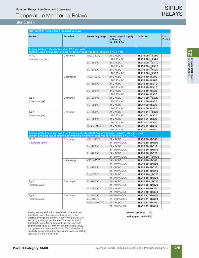
Analog setting evaluation devices with one and twothreshold values. For analog setting devices, thethreshold values and the hysteresis from 2 to 20% areset using a rotary potentiometer. For devices with 2threshold values, the selectable hysteresis only actson threshold value 1. For the second threshold value,the hysteresis is permanently set to 5%. This series ofproducts was developed for applications where a settingaccuracy of ± 5% is sufficient.
3RS10/3RS11 Temperature monitoring relays
Sensor Function Measuring range Rated control supply Order No.voltage Vs50–60 Hz AC
Analog setting, 1 threshold value, 22.5 mm wide;analog closed-circuit principle, no holding on supply failure function; 1 NO + 1 NC
PT100 Overrange –50...+50 °C 24 V AC/DC 3RS10 00- CD00
(resistance sensor) 110/230 V AC 3RS10 00- CK00
0...+100 °C 24 V AC/DC 3RS10 00- CD10
110/230 V AC 3RS10 00- CK10
0...+200 °C 24 V AC/DC 3RS10 00- CD20
110/230 V AC 3RS10 00- CK20
Underrange –50...+50 °C 24 V AC/DC 3RS10 10-1CD00
110/230 V AC 3RS10 10-1CK00
0...+100 °C 24 V AC/DC 3RS10 10-1CD10
110/230 V AC 3RS10 10-1CK10
0...+200 °C 24 V AC/DC 3RS10 10-1CD20
110/230 V AC 3RS10 10-1CK20
Typ J Overrange 0...+200 °C 24 V AC/DC 3RS11 00- CD20
(thermocouple) 110/230 V AC 3RS11 00-1CK20
0...+600 °C 24 V AC/DC 3RS11 00-1CD30
110/230 V AC 3RS11 00-1CK30
Typ K Overrange 0...+200 °C 24 V AC/DC 3RS11 01- CD20
(thermocouple) 110/230 V AC 3RS11 01-1CK20
0...+600 °C 24 V AC/DC 3RS11 01-1CD30
110/230 V AC 3RS11 01-1CK30
+500...+1000 °C 24 V AC/DC 3RS11 01-1CD40
110/230 V AC 3RS11 01-1CK40
Analog setting for alarm and trip (2 threshold values), 22.5 mm wide; open-circuit – closed-circuitcurrent principle can be toggled between; no holding on supply failure function; 1 NO + 1 CO
PT100 Overrange –50...+50 °C 24 V AC/DC 3RS10 20-1DD00
(resistance sensor) 24–240 V AC/DC 3RS10 20-1DW00
0...+100 °C 24 V AC/DC 3RS10 20-1DD10
24–240 V AC/DC 3RS10 20-1DW10
0...+200 °C 24 V AC/DC 3RS10 20-1DD20
24–240 V AC/DC 3RS10 20- DW20
Underrange –50...+50 °C 24 V AC/DC 3RS10 30-1DD00
24–240 V AC/DC 3RS10 30-1DW00
0...+100 °C 24 V AC/DC 3RS10 30-1DD10
24–240 V AC/DC 3RS10 30-1DW10
0...+ 200 °C 24 V AC/DC 3RS10 30- DD20
24–240 V AC/DC 3RS10 30-1DW20
Typ J Overrange 0...+200 °C 24 V AC/DC 3RS11 20- DD20
(thermocouple) 24–240 V AC/DC 3RS11 20-1DW20
0...+600 °C 24 V AC/DC 3RS11 20-1DD30
24–240 V AC/DC 3RS11 20-1DW30
Typ K Overrange 0...+200 °C 24–240 V AC/DC 3RS11 21-1DW20
(thermocouple) 0...+600 °C 24–240 V AC/DC 3RS11 21-1DW30
+500...+1000 °C 24 V AC/DC 3RS11 21-1DD40
24–240 V AC/DC 3RS11 21-1DW40
ListPrice $
Screw Terminal 1
Spring-type Terminal 2
Function Relays, Interfaces and Converters
Temperature Monitoring Relays3RS10/3RS11
Product Category: SMRL
SIRIUS RELAYS
Siemens Canada Limited Industrial Control Product Catalog 201912/6
12
RELA
YS, I
NTE
RFA
CES
& C
ON
VERT
ERS
Siemens / Industrial Controls Previous folio: IC10 11/6
Screw Terminal 1
Spring-type Terminal 2
11
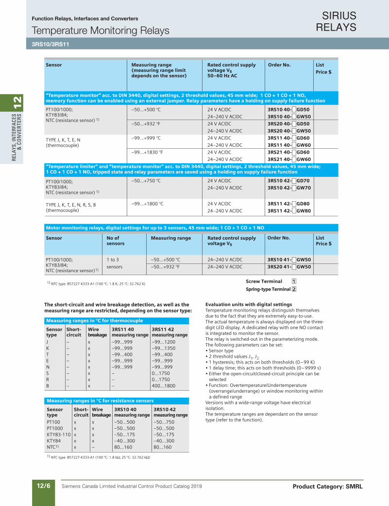
Evaluation units with digital settingsTemperature monitoring relays distinguish themselves due to the fact that they are extremely easy-to-use. The actual temperature is always displayed on the three-digit LED display. A dedicated relay with one NO contact is integrated to monitor the sensor.The relay is switched-out in the parameterizing mode.The following parameters can be set:• Sensor type• 2 threshold values J , J• 1 hysteresis; this acts on both thresholds (0–99 K)• 1 delay time; this acts on both thresholds (0–9999 s)• Either the open-circuit/closed-circuit principle can be
selected• Function: Overtemperature/Undertemperature
(overrange/underrange) or window monitoring withina defined range
Versions with a wide-range voltage have electrical isolation.The temperature ranges are dependant on the sensor type (refer to the function).
1 2
3RS10/3RS11 Temperature monitoring relays
Sensor Measuring range Rated control supply Order No. (measuring range limit voltage Vsdepends on the sensor) 50–60 Hz AC
“Temperature monitor” acc. to DIN 3440, digital settings, 2 threshold values, 45 mm wide; 1 CO + 1 CO + 1 NO,memory function can be enabled using an external jumper. Relay parameters have a holding on supply failure function
–50...+500 °C 24 V AC/DC 3RS10 40- GD50
24–240 V AC/DC 3RS10 40- GW50
–50...+932 °F 24 V AC/DC 3RS20 40- GD50
24–240 V AC/DC 3RS20 40- GW50
–99...+999 °C 24 V AC/DC 3RS11 40- GD60
24–240 V AC/DC 3RS11 40- GW60
–99...+1830 °F 24 V AC/DC 3RS21 40- GD60
24–240 V AC/DC 3RS21 40- GW60
“Temperature limiter” and “temperature monitor” acc. to DIN 3440, digital settings, 2 threshold values, 45 mm wide;1 CO + 1 CO + 1 NO, tripped state and relay parameters are saved using a holding on supply failure function
–50...+750 °C 24 V AC/DC 3RS10 42- GD70
24–240 V AC/DC 3RS10 42- GW70
–99...+1800 °C 24 V AC/DC 3RS11 42- GD80
24–240 V AC/DC 3RS11 42- GW80
The short-circuit and wire breakage detection, as well as themeasuring range are restricted, depending on the sensor type:
Measuring ranges in °C for thermocouple
Sensor Short- Wire 3RS11 40 3RS11 42type circuit breakage measuring range measuring range
J – x –99...999 –99...1200K – x –99...999 –99...1350T – x –99...400 –99...400E – x –99...999 –99...999N – x –99...999 –99...999S – x – 0...1750R – x – 0...1750B – x – 400...1800
Measuring ranges in °C for resistance sensors
Sensor Short- Wire 3RS10 40 3RS10 42type circuit breakage measuring range measuring range
PT100 x x –50...500 –50...750PT1000 x x –50...500 –50...500KTY83-110 x x –50...175 –50...175KTY84 x x –40...300 –40...300NTC1) x – 80...160 80...160
1) NTC type: B57227-K333-A1 (100 °C: 1.8 kΩ ; 25 °C: 32.762 kΩ )
Motor monitoring relays, digital settings for up to 3 sensors, 45 mm wide; 1 CO + 1 CO + 1 NO
Sensor No of Measuring range Rated control supply sensors voltage Vs
Order No.
1 to 3 –50...+500 °C 24–240 V AC/DC 3RS10 41- GW50
sensors –50...+932 °F 24–240 V AC/DC 3RS20 41- GW50
1) NTC type: B57227-K333-A1 (100 °C: 1.8 K; 25 °C: 32.762 K)
PT100/1000;KTY83/84;NTC (resistance sensor) 1)
TYPE J, K, T, E, N(thermocouple)
PT100/1000;KTY83/84;NTC (resistance sensor) 1)
TYPE J, K, T, E, N, R, S, B(thermocouple)
PT100/1000;KTY83/84;NTC (resistance sensor) 1)
ListPrice $
List
Price $
Function Relays, Interfaces and Converters
Temperature Monitoring Relays3RS10/3RS11
Product Category: SMRL
SIRIUS RELAYS
Siemens Canada Limited Industrial Control Product Catalog 2019 12/7
12
RELAYS, IN
TERFACES
& CO
NVERTERS
Siemens / Industrial Controls Previous folio: IC10 11/7
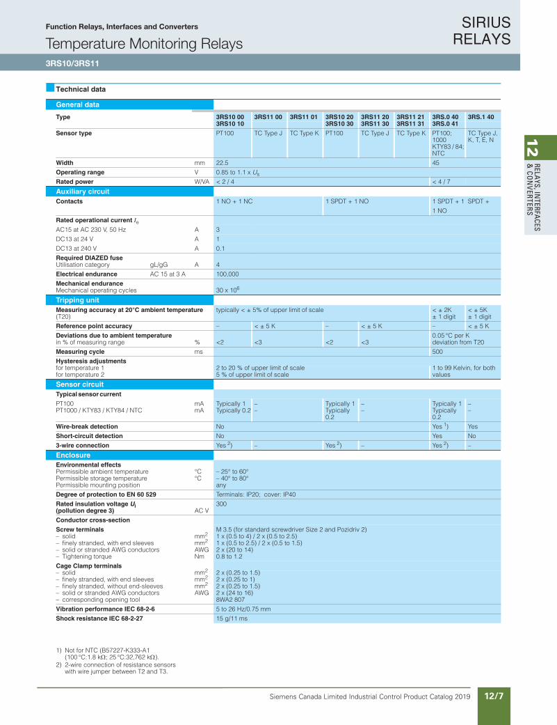
Technical data
1) Not for NTC (B57227-K333-A1(100 °C:1.8 kΩ; 25 °C:32,762 kΩ).
2) 2-wire connection of resistance sensors with wire jumper between T2 and T3.
General data
Type 3RS10 00 3RS11 00 3RS11 01 3RS10 20 3RS11 20 3RS11 21 3RS.0 40 3RS.1 403RS10 10 3RS10 30 3RS11 30 3RS11 31 3RS.0 41
Sensor type PT100 TC Type J TC Type K PT100 TC Type J TC Type K PT100; 1000KTY83 / 84; NTC
TC Type J, K, T, E, N
Width mm 22.5 45
Operating range V 0.85 to 1.1 x Us
Rated power W/VA < 2 / 4 < 4 / 7
Auxiliary circuitContacts 1 NO + 1 NC 1 SPDT + 1 NO 1 SPDT + 1 SPDT +
1 NO
Rated operational current IeAzH 05 ,V 032 CA ta 51CA 3
AV 42 ta 31CD 1
AV 042 ta 31CD 0.1
Required DIAZED fuseUtilisation category gL/gG A 4
Electrical endurance AC 15 at 3 A 100,000
Mechanical enduranceMechanical operating cycles 30 x 106
Tripping unitMeasuring accuracy at 20°C ambient temperature(T20)
typically < ± 5% of upper limit of scale < ± 2K ± 1 digit
< ± 5K ± 1 digit
Reference point accuracy – < ± 5 K – < ± 5 K – < ± 5 K
Deviations due to ambient temperature%egnar gnirusaem fo % ni <2 <3 <2 <3
0.05 °C per K deviation from T20
Measuring cycle ms 500
Hysteresis adjustmentsfor temperature 1for temperature 2
2 to 20 % of upper limit of scale5 % of upper limit of scale
1 to 99 Kelvin, for both values
Sensor circuitTypical sensor current
PT100PT1000 / KTY83 / KTY84 / NTC
mAmA
Typically 1Typically 0.2
––
Typically 1Typically 0.2
––
Typically 1Typically 0.2
––
Wire-break detection No Yes 1) Yes
Short-circuit detection No Yes No
3-wire connection Yes 2) – Yes 2) – Yes 2) –
EnclosureEnvironmental effectsPermissible ambient temperaturePermissible storage temperaturePermissible mounting position
°C°C
– 25° to 60°– 40° to 80°any
Degree of protection to EN 60 529 Terminals: IP20; cover: IP40
Rated insulation voltage Ui(pollution degree 3) AC V
300
Conductor cross-section
Screw terminals M 3.5 (for standard screwdriver Size 2 and Pozidriv 2)– solid– finely stranded, with end sleeves– solid or stranded AWG conductors– Tightening torque
mm2
mm2
AWGNm
1 x (0.5 to 4) / 2 x (0.5 to 2.5)1 x (0.5 to 2.5) / 2 x (0.5 to 1.5)2 x (20 to 14)0.8 to 1.2
Cage Clamp terminals– solid– finely stranded, with end sleeves– finely stranded, without end-sleeves– solid or stranded AWG conductors– corresponding opening tool
mm2
mm2
mm2
AWG
2 x (0.25 to 1.5)2 x (0.25 to 1)2 x (0.25 to 1.5)2 x (24 to 16)8WA2 807
Vibration performance IEC 68-2-6 5 to 26 Hz/0.75 mm
Shock resistance IEC 68-2-27 15 g/11 ms
Function Relays, Interfaces and Converters
Temperature Monitoring Relays3RS10/3RS11
SIRIUS RELAYS
Siemens Canada Limited Industrial Control Product Catalog 201912/8
12
RELA
YS, I
NTE
RFA
CES
& C
ON
VERT
ERS
Siemens / Industrial Controls Previous folio: IC10 11/8
Configuration
SpecificationsThe temperature monitoring relays correspond to:• IEC 60 721-3-3 "Environmental
conditions"• IEC 947-5-1; DIN VDE 0660
"Low-voltage switchgear and controlgear"
• EN 50 081-2 "Basic technical standard for emitted interfer-ence (industry)"
• EN 61 000-6-2 "Basic techni-cal stand ard for interference immunity (industry)"
• DIN EN 50 042 "Terminal marking"
• UL/CSA under application
Specifications
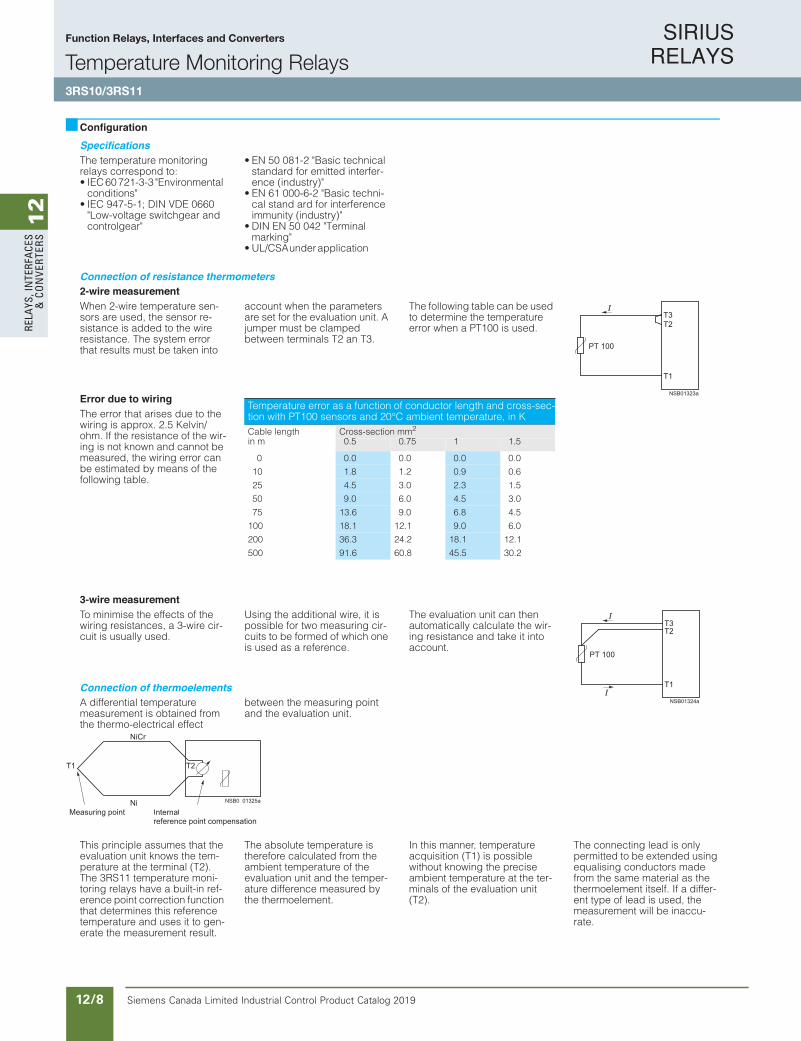
Connection of resistance thermometers2-wire measurementWhen 2-wire temperature sen-sors are used, the sensor re-sistance is added to the wire resistance. The system error that results must be taken into
account when the parameters are set for the evaluation unit. A jumper must be clamped between terminals T2 an T3.
The following table can be used to determine the temperature error when a PT100 is used.
Error due to wiringThe error that arises due to the wiring is approx. 2.5 Kelvin/ohm. If the resistance of the wir-ing is not known and cannot be measured, the wiring error can be estimated by means of the following table.
3-wire measurementTo minimise the effects of the wiring resistances, a 3-wire cir-cuit is usually used.
Using the additional wire, it is possible for two measuring cir-cuits to be formed of which one is used as a reference.
The evaluation unit can then automatically calculate the wir-ing resistance and take it into account.
Connection of thermoelementsA differential temperature measurement is obtained from the thermo-electrical effect
between the measuring point and the evaluation unit.
This principle assumes that the evaluation unit knows the tem-perature at the terminal (T2). The 3RS11 temperature moni-toring relays have a built-in ref-erence point correction function that determines this reference temperature and uses it to gen-erate the measurement result.
The absolute temperature is therefore calculated from the ambient temperature of the evaluation unit and the temper-ature difference measured by the thermoelement.
In this manner, temperature acquisition (T1) is possible without knowing the precise ambient temperature at the ter-minals of the evaluation unit (T2).
The connecting lead is only permitted to be extended using equalising conductors made from the same material as the thermoelement itself. If a differ-ent type of lead is used, the measurement will be inaccu-rate.
Temperature error as a function of conductor length and cross-sec-tion with PT100 sensors and 20°C ambient temperature, in KCable length Cross-section mm2
in m 0.5 0.75 1 1.5
0 0.0 0.0 0.0 0.0
10 1.8 1.2 0.9 0.6
25 4.5 3.0 2.3 1.5
50 9.0 6.0 4.5 3.0
75 13.6 9.0 6.8 4.5
100 18.1 12.1 9.0 6.0
200 36.3 24.2 18.1 12.1
500 91.6 60.8 45.5 30.2
Function Relays, Interfaces and Converters
Temperature Monitoring Relays3RS10/3RS11

SIRIUS RELAYS
Siemens Canada Limited Industrial Control Product Catalog 2019 12/9
12
RELAYS, IN
TERFACES
& CO
NVERTERS
Siemens / Industrial Controls Previous folio: IC10 11/9
Functions
Temperature overshootelpicnirp tiucric-desolCelpicnirp tiucric-nepO
Digital evaluation units:After the temperature has reached the set threshold value ϑ1, output relay K1 changes its switching state appropriately as soon as the set time t has elapsed (K2 responds to ϑ2similarly).
Analog evaluation units:When the set threshold value is reached, out-put relay K1 changes its switching status. For devices with 2 threshold values, relay K2 responds to the second set threshold value. As soon as the temperature reaches the respective set hysteresis value, the relays return immediately to the original state.A time delay cannot be set (t = 0).
Temperature undershootelpicnirp tiucric-desolCelpicnirp tiucric-nepO
Window monitoringelpicnirp tiucric-desolCelpicnirp tiucric-nepO
When the temperature has reached the upper threshold ϑ1 and the set delay time t has elapsed, the output relay K1 changes its switching state. As soon as the temperature reaches the respective set hysteresis value, the relay returns immediately to the original state.In the same manner, K2 responds to the lower threshold value of ϑ2.
Principle of operation with memory function, based on the example of temperature overshoot using the closed-circuit principle
When the temperature has reached the set threshold ϑ1 and the set delay time t has elapsed, the output relay K1 changes its switching state (similarly, K2 responds toϑ2.)
The relays will only return to the original state when the temperature has fallen below the respective set hysteresis value and the con-nection Y1-Y2 was briefly interrupted.
Function Relays, Interfaces and Converters
Temperature Monitoring Relays3RS10/3RS11

SIRIUS RELAYS
Siemens Canada Limited Industrial Control Product Catalog 201912/10
12
RELA
YS, I
NTE
RFA
CES
& C
ON
VERT
ERS
Siemens / Industrial Controls Previous folio: IC10 11/10
Circuit diagrams
Connection examples3RS10 003RS10 10
3RS11 003RS11 01
General equipment designations
A1, A2, A3 Rated control supply volt-age terminals
K1, K2, K3 Output relays
Equipment designations for: 3RS1000, 3RS1010, 3RS1101, 3RS1100, 3RS1110, 3RS1111, 3RS1020, 3RS1021, 3RS1030, 3RS1031
= LED: "Voltage applied"ϑ1 = LED: "Relay 1 switched"ϑ2 = LED: "Relay 2 switched"T1 to T3 = Terminals for connection of
resistance sensorT+ / T- = Terminals for connection of
thermoelements
Equipment designations for: 3RS1040, 3RS1140, 3RS2040, 3RS2140
ϑ1 = LED: "Relay 1 switched"ϑ2 = LED: "Relay 2 switched"Ready = LED: "Device operating"
T1 to T3 = Terminals for connection of resistance sensor
T+ / T- = Terminals for connection of thermoelements
Y1/Y2 Terminals for memory jumper JBiq
Equipment designations for: 3RS1041, 3RS2041
ϑ1 = LED: "Relay 1 switched"ϑ2 = LED: "Relay 2 switched"Ready = LED: "Device operating"
1T1 to 1T3 = Terminals for connection of resistance sensor 1
2T1 to 2T3 = Terminals for connection of resistance sensor 2
3T1 to 3T3 = Terminals for connection of resistance sensor 3
Y1/Y2 Terminals for memory jumper
. Important!When resistance sensors are used in a 2-wire con-nection, a jumper must be installed between T2 and T3.
3RS10 203RS10 30
3RS11 20/3RS11 303RS11 21/3RS11 31
3RS10 403RS20 40
3RS10 413RS20 41
3RS11 403RS21 40
Function Relays, Interfaces and Converters
Temperature Monitoring Relays3RS10/3RS11
SIRIUS RELAYS
Siemens Canada Limited Industrial Control Product Catalog 2019 12/11
12
RELAYS, IN
TERFACES
& CO
NVERTERS
Siemens / Industrial Controls Previous folio: IC10 11/11
Dimension drawings
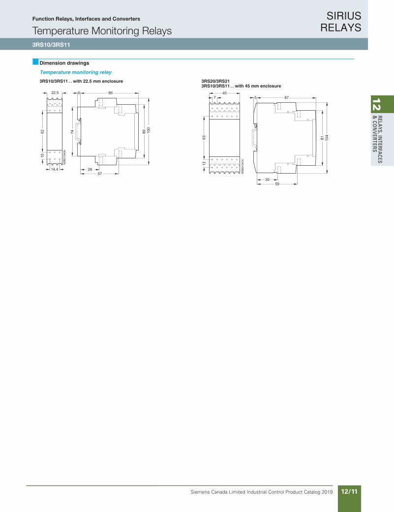
Temperature monitoring relay
3RS10/3RS11 . 12SR3/02SR3erusolcne mm 5.22 htiw .3RS10/3RS11 . . with 45 mm enclosure
Function Relays, Interfaces and Converters
Temperature Monitoring Relays3RS10/3RS11
SIRIUS RELAYS
Siemens Canada Limited Industrial Control Product Catalog 201912/12
12
RELA
YS, I
NTE
RFA
CES
& C
ON
VERT
ERS
Siemens / Industrial Controls Previous folio: IC10 11/12
Relays
Thermistor Motor Protection3RN2
10/157Siemens IC 10 · 2018
Relays
SIRIUS 3RN2 thermistor motor protection
10
Overview
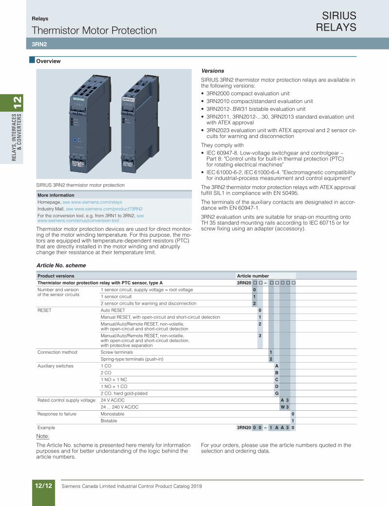
SIRIUS 3RN2 thermistor motor protection
Thermistor motor protection devices are used for direct monitor-ing of the motor winding temperature. For this purpose, the mo-tors are equipped with temperature-dependent resistors (PTC) that are directly installed in the motor winding and abruptly change their resistance at their temperature limit.
Versions
SIRIUS 3RN2 thermistor motor protection relays are available in the following versions:• 3RN2000 compact evaluation unit• 3RN2010 compact/standard evaluation unit• 3RN2012-.BW31 bistable evaluation unit• 3RN2011, 3RN2012-...30, 3RN2013 standard evaluation unit
with ATEX approval• 3RN2023 evaluation unit with ATEX approval and 2 sensor cir-
cuits for warning and disconnection
They comply with• IEC 60947-8. Low-voltage switchgear and controlgear –
Part 8: "Control units for built-in thermal protection (PTC) for rotating electrical machines"
• IEC 61000-6-2, IEC 61000-6-4. "Electromagnetic compatibility for industrial-process measurement and control equipment"
The 3RN2 thermistor motor protection relays with ATEX approval fulfill SIL1 in compliance with EN 50495.
The terminals of the auxiliary contacts are designated in accor-dance with EN 60947-1.
3RN2 evaluation units are suitable for snap-on mounting ontoTH 35 standard mounting rails according to IEC 60715 or for screw fixing using an adapter (accessory).
Article No. scheme
Note:
The Article No. scheme is presented here merely for information purposes and for better understanding of the logic behind the article numbers.
For your orders, please use the article numbers quoted in the selection and ordering data.
More information
Homepage, see www.siemens.com/relays
Industry Mall, see www.siemens.com/product?3RN2
For the conversion tool, e.g. from 3RN1 to 3RN2, see www.siemens.com/sirius/conversion-tool
Product versions Article number
Thermistor motor protection relay with PTC sensor, type A 3RN20 @ @ – @ @ @ @ @
Number and version of the sensor circuits
1 sensor circuit, supply voltage = root voltage 0
1 sensor circuit 1
2 sensor circuits for warning and disconnection 2
RESET Auto RESET 0
Manual RESET, with open-circuit and short-circuit detection 1
Manual/Auto/Remote RESET, non-volatile, with open-circuit and short-circuit detection
2
Manual/Auto/Remote RESET, non-volatile, with open-circuit and short-circuit detection, with protective separation
3
Connection method Screw terminals 1
Spring-type terminals (push-in) 2
Auxiliary switches 1 CO A
2 CO B
1 NO + 1 NC C
1 NO + 1 CO D
2 CO, hard gold-plated G
Rated control supply voltage 24 V AC/DC A 3
24 ... 240 V AC/DC W 3
Response to failure Monostable 0
Bistable 1
Example 3RN20 0 0 – 1 A A 3 0
IC10_10_13.fm Page 157 Tuesday, March 13, 2018 12:45 PM
SIRIUS RELAYS
Siemens Canada Limited Industrial Control Product Catalog 2019 12/13
12
RELAYS, IN
TERFACES
& CO
NVERTERS
Siemens / Industrial Controls Previous folio: IC10 11/13
Relays
Thermistor Motor Protection3RN2
Product Category: SMRL
10/158 Siemens IC 10 · 2018
Relays
SIRIUS 3RN2 thermistor motor protection
10
Benefits
• Thanks to direct motor protection, overdimensioning of the motors is not necessary
• No settings on the device are necessary• Semiconductor compatible output thanks to versions with
hard gold-plated contacts
• Rapid error diagnosis thanks to versions that indicate open and short circuits in the sensor circuit
• All versions with removable terminals• All versions with screw or spring-type terminals with push-in
functionality
Application
Direct motor protection through temperature monitoring of the motor winding offers 100% motor protection even under the most difficult ambient conditions, without the need to make ad-justments on the device. Versions with hard gold-plated contacts ensure, in addition, a high switching reliability that is even higher than an electronic control.
Direct motor protection• At increased ambient temperatures• When switching frequency is too high• When start up and braking procedures are too long
ATEX approval for operation in areas subject to explosion hazard
The SIRIUS 3RN2011, 3RN2012-...30, 3RN2013 and 3RN2023 thermistor motor protection relays for PTC sensors are certified according to ATEX Ex II (2) G and D for environments with explo-sive gas or dust loads.
Motor protection using current- and temperature-dependent protective devices
IEC 60204 stipulates that motors must be protected from over-heating at a rating of 0.5 kW and higher. The protection can take the form of overload protection, overtemperature protection or current limiting.
For motors with frequent starting and braking and in environ-ments where cooling may be impaired (e.g. by dust), it is recom-mended to use the overtemperature protection option in the form of a protective device coordinated with this mode of operation. A good choice in this case is the use of 3RN2 thermistor motor protection devices.
On rotor-critical motors, overtemperature detection in the stator windings can lead to delayed and hence inadequate protection. In this case the standards stipulate additional protection, e.g. by means of an overload relay.
This combination of thermistor motor protection and an overload relay is recommended for full motor protection in case of fre-quent starting and braking of motors, irregular intermittent duty or excessive switching frequency. To prevent premature tripping of the overload relay in such operating conditions, a higher set-ting than that normally required for the operational current is cho-sen. The overload relay then performs stall protection, and the 3RN2 thermistor motor protection relay monitors the temperature of the motor windings.
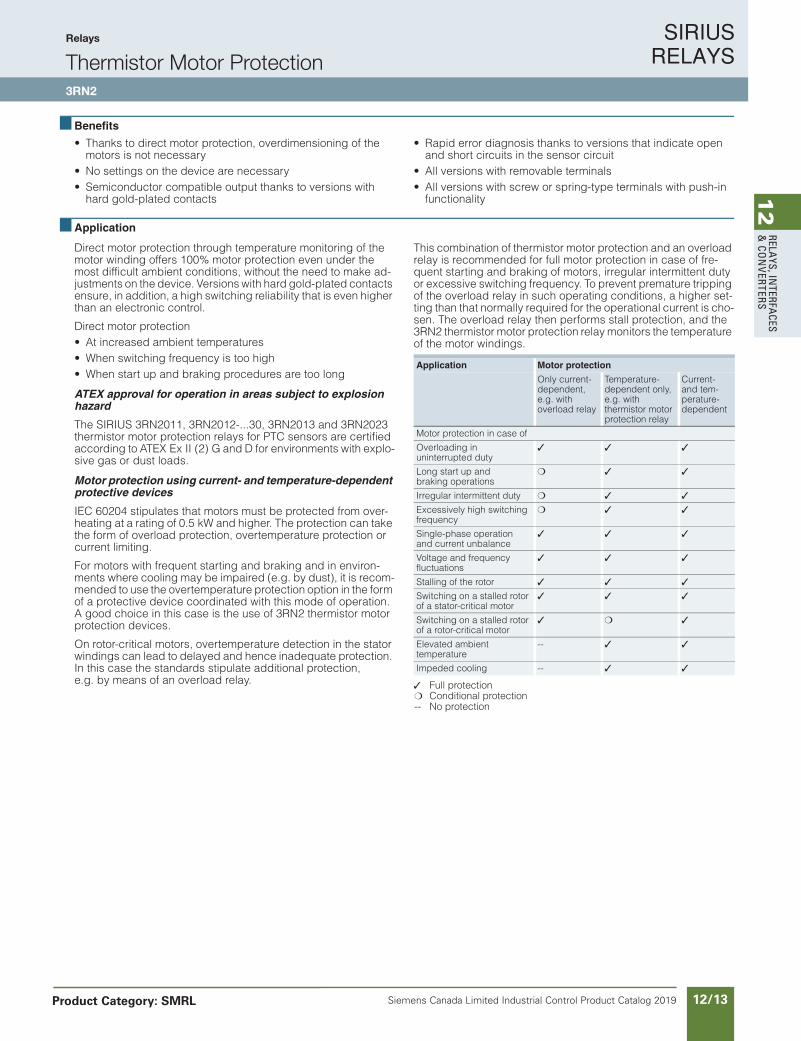
Full protection Conditional protection-- No protection
Application Motor protection
Only current-dependent, e.g. withoverload relay
Temperature-dependent only, e.g. withthermistor motor protection relay
Current- and tem-perature-dependent
Motor protection in case of
Overloading in uninterrupted duty
Long start up and braking operations
Irregular intermittent duty
Excessively high switching frequency
Single-phase operation and current unbalance
Voltage and frequency fluctuations
Stalling of the rotor
Switching on a stalled rotor of a stator-critical motor
Switching on a stalled rotor of a rotor-critical motor
Elevated ambienttemperature
--
Impeded cooling --
IC10_10_13.fm Page 158 Tuesday, March 13, 2018 12:45 PM
SIRIUS RELAYS
Siemens Canada Limited Industrial Control Product Catalog 201912/14
12
RELA
YS, I
NTE
RFA
CES
& C
ON
VERT
ERS
Siemens / Industrial Controls Previous folio: IC10 11/14
Relays
Thermistor Motor Protection3RN2
10/159Siemens IC 10 · 2018
Relays
SIRIUS 3RN2 thermistor motor protection
10
Technical specifications
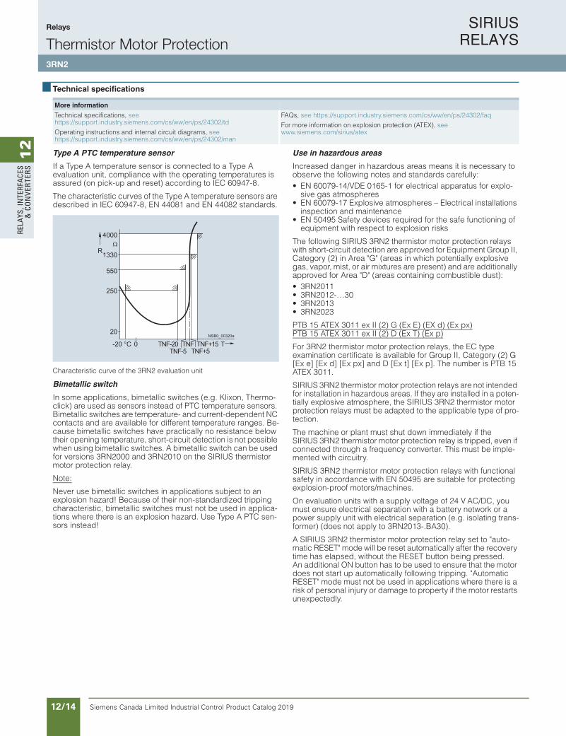
Type A PTC temperature sensor
If a Type A temperature sensor is connected to a Type A evaluation unit, compliance with the operating temperatures is assured (on pick-up and reset) according to IEC 60947-8.
The characteristic curves of the Type A temperature sensors are described in IEC 60947-8, EN 44081 and EN 44082 standards.
Characteristic curve of the 3RN2 evaluation unit
Bimetallic switch
In some applications, bimetallic switches (e.g. Klixon, Thermo-click) are used as sensors instead of PTC temperature sensors. Bimetallic switches are temperature- and current-dependent NC contacts and are available for different temperature ranges. Be-cause bimetallic switches have practically no resistance below their opening temperature, short-circuit detection is not possible when using bimetallic switches. A bimetallic switch can be used for versions 3RN2000 and 3RN2010 on the SIRIUS thermistor motor protection relay.
Note:
Never use bimetallic switches in applications subject to an explosion hazard! Because of their non-standardized tripping characteristic, bimetallic switches must not be used in applica-tions where there is an explosion hazard. Use Type A PTC sen-sors instead!
Use in hazardous areas
Increased danger in hazardous areas means it is necessary to observe the following notes and standards carefully: • EN 60079-14/VDE 0165-1 for electrical apparatus for explo-
sive gas atmospheres • EN 60079-17 Explosive atmospheres – Electrical installations
inspection and maintenance • EN 50495 Safety devices required for the safe functioning of
equipment with respect to explosion risks
The following SIRIUS 3RN2 thermistor motor protection relays with short-circuit detection are approved for Equipment Group II, Category (2) in Area "G" (areas in which potentially explosivegas, vapor, mist, or air mixtures are present) and are additionally approved for Area "D" (areas containing combustible dust):• 3RN2011• 3RN2012-…30• 3RN2013• 3RN2023
PTB 15 ATEX 3011 ex II (2) G (Ex E) (EX d) (Ex px)PTB 15 ATEX 3011 ex II (2) D (Ex T) (Ex p)
For 3RN2 thermistor motor protection relays, the EC type examination certificate is available for Group II, Category (2) G [Ex e] [Ex d] [Ex px] and D [Ex t] [Ex p]. The number is PTB 15 ATEX 3011.
SIRIUS 3RN2 thermistor motor protection relays are not intended for installation in hazardous areas. If they are installed in a poten-tially explosive atmosphere, the SIRIUS 3RN2 thermistor motor protection relays must be adapted to the applicable type of pro-tection.
The machine or plant must shut down immediately if the SIRIUS 3RN2 thermistor motor protection relay is tripped, even if connected through a frequency converter. This must be imple-mented with circuitry.
SIRIUS 3RN2 thermistor motor protection relays with functional safety in accordance with EN 50495 are suitable for protecting explosion-proof motors/machines.
On evaluation units with a supply voltage of 24 V AC/DC, you must ensure electrical separation with a battery network or a power supply unit with electrical separation (e.g. isolating trans-former) (does not apply to 3RN2013-.BA30).
A SIRIUS 3RN2 thermistor motor protection relay set to "auto-matic RESET" mode will be reset automatically after the recovery time has elapsed, without the RESET button being pressed. An additional ON button has to be used to ensure that the motor does not start up automatically following tripping. "Automatic RESET" mode must not be used in applications where there is a risk of personal injury or damage to property if the motor restarts unexpectedly.
More information
Technical specifications, seehttps://support.industry.siemens.com/cs/ww/en/ps/24302/td
Operating instructions and internal circuit diagrams, seehttps://support.industry.siemens.com/cs/ww/en/ps/24302/man
FAQs, see https://support.industry.siemens.com/cs/ww/en/ps/24302/faq
For more information on explosion protection (ATEX), see www.siemens.com/sirius/atex
TNF+5
NSB0_00320a
R
TTNF+15TNFTNF-5
TNF-200-20 °C
20
250
550
1330
4000
IC10_10_13.fm Page 159 Tuesday, March 13, 2018 12:45 PM
SIRIUS RELAYS
Siemens Canada Limited Industrial Control Product Catalog 2019 12/15
12
RELAYS, IN
TERFACES
& CO
NVERTERS
Siemens / Industrial Controls Previous folio: IC10 11/15
Relays
Thermistor Motor Protection3RN2
10/160 Siemens IC 10 · 2018
Relays
SIRIUS 3RN2 thermistor motor protection
10
. NOTICE!
When used in a hazardous area, the thermistor motor protection relay must not be operated with automatic RESET (terminal Y1 and Y2 permanently jumpered).
A risk analysis must be performed for the complete plant or machine. If this analysis yields a lower hazard potential (category 1), all SIRIUS 3RN2 thermistor motor protection relays can be used, provided the safety regulations are observed.
. WARNING!
All work involved in connecting, commissioning and mainte-nance must be carried out by qualified, responsible personnel. Improper handling may result in serious personal injury and considerable damage to property.
Cable routing
The measuring circuit leads must be routed as separate control cables. It is not permitted to use cores from the supply line of the motor or any other main supply cables. If extreme inductive or capacitive interference is expected as a result of power lines routed in parallel, shielded control cables must be used.
Maximum length of sensor circuit cables for evaluation units without short-circuit detection in the sensor circuit:
Maximum length of sensor circuit cables for evaluation units with short-circuit detection1)
1) A short circuit in the sensor circuit will be detected up to this maximum cable length.
Principle of operation
SIRIUS 3RN2 thermistor motor protection relays are thermal protection devices that are suitable, in combination with type A PTC thermistors, for monitoring temperatures of electrical drives, transformer windings, oils, bearings, air, etc.
The most frequent application is monitoring of three-phase mo-tors in which the motor manufacturer has fitted a PTC sensor into every winding overhang and in which these PTC sensors are connected in series.
The SIRIUS 3RN2 thermistor motor protection relays operate in accordance with the closed-circuit principle and therefore mon-itor themselves for loss of supply voltage. The exceptions are the warning output on 3RN2023, which always works on the open-circuit principle and the bistable relays of the 3RN2012-.BW31, which always retain the last switching state.
A micro-interruption in the power supply of less than 30 ms does not change the status of the output relays.
For devices with the "Manual RESET" function, the test function can be activated and a trip simulated by pressing the blue Test/RESET button for > 2 seconds.
The 3RN2011, 3RN2012, 3RN2013 and 3RN2023 devices are additionally equipped with open-circuit and short-circuit detec-tion in the sensor circuit. The unit will trip in the event of a short-circuit (resistance in sensor circuit < 10 ) or open circuit in the sensor circuit (dynamic open-circuit detection). Tripping as the result of a short-circuit in the sensor circuit is indicated by a flick-ering red LED (TRIPPED). In the event of a short-circuit in the sensor circuit for warning on the 3RN2023, the yellow warning LED (WARNING) flickers. The devices with dynamic open-circuit detection evaluate the rise time of the sensor circuit resistance. If the sensor circuit resistance rises from 3 300 to 12 k within 200 ms, the unit will not only trip, but also indicate the open cir-cuit via a flashing red LED (TRIPPED). In the event of an open circuit in a sensor circuit, the yellow warning LED (WARNING) flashes for the 3RN2023.
All evaluation units (except for the 3RN2000 compact evaluation unit) feature electrical separation between the control circuit and the sensor circuit. The relay outputs are also electrically sepa-rated from all other circuits. The 3RN2013 and 3RN2023 evalua-tion units incorporate protective electrical separation between all circuits up to Ui = 300 V.
3RN2000 compact evaluation unit
The compact unit, which is only 17.5 mm wide, is equipped with a red LED (TRIPPED) for the tripped indicator and a changeover contact. After the unit has tripped, it is automatically reset once the thermistors have cooled down. The root of the changeover contact is connected to the control voltage (terminal 11 is con-nected to terminal A1). This unit is particularly suitable in circuits in which the control circuit and signaling circuit have the same potential, e.g. in local control boxes.
3RN2010, 3RN2011, 3RN2012 and 3RN2013 compact/standardevaluation units
The units are equipped with two LEDs (READY and TRIPPED) for an operating and tripped display and are available with either 1 NO + 1 NC contacts (3RN2010, overall width 17.5 mm) or with 2 CO contacts. Depending on the version, they are available with Auto RESET (3RN2010), Manual/Remote RESET (3RN2011) or Manual/Auto and Remote RESET (3RN2012 and 3RN2013). Remote RESET can be achieved by connecting an external pushbutton with a normally-open function to terminals Y1 and Y2. If terminals Y1 and Y2 are jumpered, the unit is automatically reset once the thermistors have cooled down (Auto RESET). 3RN2012 and 3RN2013 are non-volatile. This means a previous trip remains stored in the event of a control supply voltage failure – the thermistor motor protection relay remains in the safe state with an opened output relay until it is intentionally reset by press-ing the TEST/RESET button of the unit or an external pushbutton.
3RN2023 "warning and disconnection" evaluation units
Two sensor circuits can be connected to one 3RN2023 evalua-tion unit that act on two separate output relays with 1 NO contact for warning and 1 CO contact for disconnection. Thermistors with different rated response temperatures TNF are used to im-plement the "Warning" and "Disconnection" functions. When sen-sor circuit 2 for "Warning" responds, a yellow LED is lit and when the "Disconnection" circuit responds, a red LED is lit. The sensor circuits have a different reset response and operating behavior: The "Warning" thermistor sensor circuit 2 (terminals 2T1, T2) works only with Auto RESET and according to the open-circuit principle (output relay K2, NO contact). The "Disconnection" thermistor sensor circuit 1, (terminals 1T1, T2) can be changed from Manual RESET to Auto RESET by jumpering terminals Y1 and Y2. Remote RESET is implemented by connecting an exter-nal pushbutton with a normally-open function to these terminals.
Cable cross-section 3RN2000, 3RN2010
2.5 mm² 2 x 2800 m
1.5 mm² 2 x 1500 m
0.5 mm² 2 x 500 m
Cable cross-section 3RN2011, 3RN2012, 3RN2013, 3RN2023
2.5 mm² 2 x 250 m
1.5 mm² 2 x 150 m
0.5 mm² 2 x 50 m
IC10_10_13.fm Page 160 Tuesday, March 13, 2018 12:45 PM
SIRIUS RELAYS
Siemens Canada Limited Industrial Control Product Catalog 201912/16
12
RELA
YS, I
NTE
RFA
CES
& C
ON
VERT
ERS
Siemens / Industrial Controls Previous folio: IC10 11/16
Relays
Thermistor Motor Protection3RN2
10/161Siemens IC 10 · 2018
Relays
SIRIUS 3RN2 thermistor motor protection
10
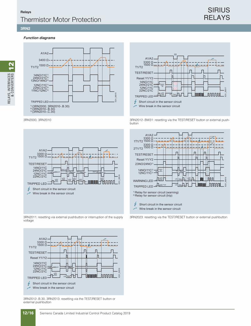
Function diagrams
3RN2000, 3RN2010
3RN2011: resetting via external pushbutton or interruption of the supply voltage
3RN2012-.B.30, 3RN2013: resetting via the TEST/RESET button or external pushbutton
3RN2012-.BW31: resetting via the TEST/RESET button or external push-button
3RN2023: resetting via the TEST/RESET button or external pushbutton
IC01
_005
15
A1/A2
T1/T2
14NO/11C1)
24NO/21C2)
13NO/14NO3)
12NC/11C1)
22NC/21C2)
11NC/12NC3)
1) (3RN2000; 3RN2010-.B.30)2) (3RN2010-.B.30)3) (3RN2010-.C.30)
3400 Ω
1500 Ω
TRIPPED LED
IC01
_005
16
A1/A2
T1/T23300 Ω1500 Ω
14NO/11C24NO/21C12NC/11C22NC/21C
TRIPPED LED
start-up start-up start-up
LEDTest
LEDTest
LEDTest
start-up
LEDTest
LEDTest
start-up
LEDTest
Short circuit in the sensor circuitWire break in the sensor circuit
TEST/RESET
IC01
_005
18
A1/A2
T1/T2
3300 Ω1500 Ω
14NO/11C24NO/21C12NC/11C22NC/21C
TRIPPED LED
start-up start-up
LED Test
LED Test
TEST/RESET
Reset Y1/Y2
Short circuit in the sensor circuitWire break in the sensor circuit
!!!
IC01
_005
17
A1/A2
T1/T2
3300 Ω1500 Ω
TRIPPED LED
start-up
LEDTest LED Test
14NO/11C24NO/21C12NC/11C22NC/21C
TEST/RESET
Reset Y1/Y2
Short circuit in the sensor circuitWire break in the sensor circuit
IC01
_005
19
1T1/T2
A1/A2
2T1/T2
3300 Ω
3300 Ω1500 Ω
1500 Ω
WARNING LED
TRIPPED LED
23NO/24NO1)
14NO/11C2)
12NC/11C2)
LEDTest
start-up start-up
LED Test
LED Test
LED Test
LED Test
1) Relay for sensor circuit (warning)
TEST/RESET
Reset Y1/Y2
2) Relay for sensor circuit (trip)
Short circuit in the sensor circuitWire break in the sensor circuit
IC10_10_13.fm Page 161 Tuesday, March 13, 2018 12:45 PM
SIRIUS RELAYS
Siemens Canada Limited Industrial Control Product Catalog 2019 12/17
12
RELAYS, IN
TERFACES
& CO
NVERTERS
Siemens / Industrial Controls Previous folio: IC10 11/17
Relays
Thermistor Motor Protection3RN2
10/162 Siemens IC 10 · 2018
Relays
SIRIUS 3RN2 thermistor motor protection
10
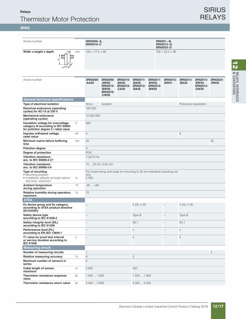
Article number 3RN2000-.A,3RN2010-.C
3RN201.-.B,3RN2013-.G,3RN2023-.D
Width x height x depth mm 100 × 17.5 × 90 100 × 22.5 × 90
W
H
D
Article number 3RN2000-.AA30
3RN2000-.AW30,3RN2010-.BW30,3RN2010-.CW30
3RN2010-.BA30,3RN2010-.CA30
3RN2011-.BA30,3RN2012-.BA30
3RN2011-.BW30,3RN2012-.BW30
3RN2012-.BW31
3RN2013-.BA30
3RN2013-.BW30,3RN2013-.GW30
3RN2023-.DW30
General technical specifications
Type of electrical isolation None Isolated Protective separation
Electrical endurance (operating cycles) for AC-15 at 230 V
100 000
Mechanical endurance(operating cycles)
10 000 000
Insulation voltage for overvoltage category III according to IEC 60664 for pollution degree 3 / rated value
V 300
Impulse withstand voltage, rated value
kV 4 6
Minimum mains failure buffering time
ms 40 30
Pollution degree 3
Degree of protection IP20
Vibration resistance acc. to IEC 60068-2-27
11g/15 ms
Vibration resistance acc. to IEC 60068-2-6
10 ... 55 Hz: 0.35 mm
Type of mounting For screw-fixing and snap-on mounting to 35 mm standard mounting rail• Mounting position Any• Installation altitude at height above
sea level, maximumm 2 000
Ambient temperature during operation
°C -25 ... +60
Relative humidity during operation, maximum
% 70
ATEXEx device group and Ex category according to ATEX product directive 2014/34/EU
-- II 2G, II 2D -- II 2G, II 2D
Safety device type according to IEC 61508-2
-- Type B -- Type B
Safety integrity level (SIL) according to IEC 61508
-- SIL1 -- SIL1
Performance level (PL) according to EN ISO 13849-1
-- c -- c
T1 value for proof test interval or service duration according to IEC 61508
y -- 3 -- 3
Measuring circuitNumber of measuring circuits 1 2
Relative measuring accuracy % 9 2
Maximum number of sensors in series
6
Cable length of sensor, maximum
m 2 800 250
Thermistor resistance response value
1 500 ... 1 650 1 500 ... 1 550
Thermistor resistance return value 3 400 ... 3 600 3 300 ... 3 350
IC10_10_13.fm Page 162 Tuesday, March 13, 2018 12:45 PM
SIRIUS RELAYS
Siemens Canada Limited Industrial Control Product Catalog 201912/18
12
RELA
YS, I
NTE
RFA
CES
& C
ON
VERT
ERS
Siemens / Industrial Controls Previous folio: IC10 11/18
Relays
Thermistor Motor Protection3RN2
10/163Siemens IC 10 · 2018
Relays
SIRIUS 3RN2 thermistor motor protection
10
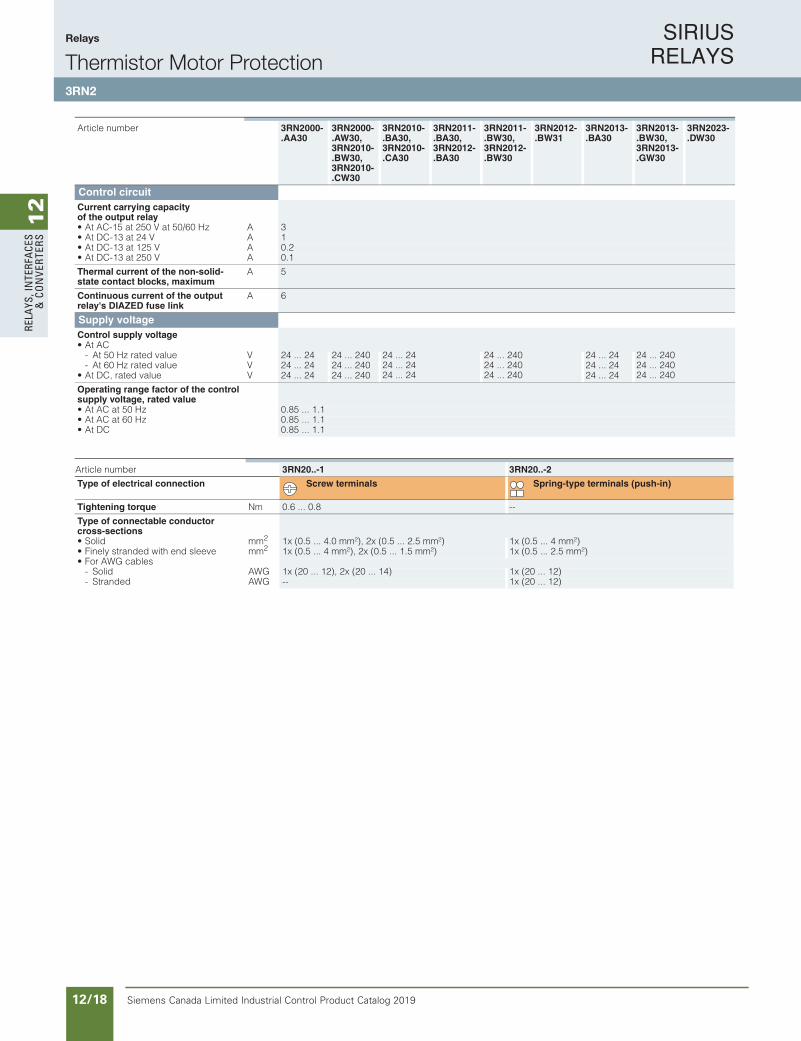
Control circuitCurrent carrying capacity of the output relay• At AC-15 at 250 V at 50/60 Hz A 3• At DC-13 at 24 V A 1• At DC-13 at 125 V A 0.2• At DC-13 at 250 V A 0.1
Thermal current of the non-solid-state contact blocks, maximum
A 5
Continuous current of the output relay's DIAZED fuse link
A 6
Supply voltageControl supply voltage• At AC
- At 50 Hz rated value V 24 ... 24 24 ... 240 24 ... 2424 ... 2424 ... 24
24 ... 24024 ... 24024 ... 240
24 ... 24 24 ... 24024 ... 24024 ... 240
- At 60 Hz rated value V 24 ... 24 24 ... 240 24 ... 24• At DC, rated value V 24 ... 24 24 ... 240 24 ... 24
Operating range factor of the control supply voltage, rated value• At AC at 50 Hz 0.85 ... 1.1• At AC at 60 Hz 0.85 ... 1.1• At DC 0.85 ... 1.1
Article number 3RN2000-.AA30
3RN2000-.AW30,3RN2010-.BW30,3RN2010-.CW30
3RN2010-.BA30,3RN2010-.CA30
3RN2011-.BA30,3RN2012-.BA30
3RN2011-.BW30,3RN2012-.BW30
3RN2012-.BW31
3RN2013-.BA30
3RN2013-.BW30,3RN2013-.GW30
3RN2023-.DW30
Article number 3RN20..-1 3RN20..-2
Type of electrical connection Screw terminals Spring-type terminals (push-in)
Tightening torque Nm 0.6 ... 0.8 --
Type of connectable conductor cross-sections• Solid mm2 1x (0.5 ... 4.0 mm²), 2x (0.5 ... 2.5 mm²) 1x (0.5 ... 4 mm²)• Finely stranded with end sleeve mm2 1x (0.5 ... 4 mm²), 2x (0.5 ... 1.5 mm²) 1x (0.5 ... 2.5 mm²)• For AWG cables
- Solid AWG 1x (20 ... 12), 2x (20 ... 14) 1x (20 ... 12)- Stranded AWG -- 1x (20 ... 12)
IC10_10_13.fm Page 163 Tuesday, March 13, 2018 12:45 PM

SIRIUS RELAYS
Siemens Canada Limited Industrial Control Product Catalog 2019 12/19
12
RELAYS, IN
TERFACES
& CO
NVERTERS
Siemens / Industrial Controls Previous folio: IC10 11/19
Relays
Thermistor Motor Protection3RN2
10/164 Siemens IC 10 · 2018* You can order this quantity or a multiple thereof.
Illustrations are approximate
Relays
SIRIUS 3RN2 thermistor motor protection
10
Selection and ordering data
1) For 3RN2011: The unit can be reset with the RESET button or by disconnecting the control supply voltage.
2) Protective separation up to 300 V acc. to DIN/VDE 0160, IEC 60947-1.3) Protection against voltage failure or non-volatile fault storage means that
previous tripping due to a fault remains stored even if the control supply voltage fails. The monitoring device is not reset if the voltage fails. With an active fault, meaning a fault which has not been manually confirmed, an automatic restart of the plant upon recovery of the power is prevented therefore and plant safety increased as the result.
3RN2000-1AA30 3RN2010-1BA30 3RN2011-1BA30 3RN2012-1BW30 3RN2023-1DW30
Product function Number of CO con-tacts for auxiliary contacts
Number of NO con-tacts for auxiliary contacts
Number of NC con-tacts for auxiliary contacts
Material of switching contacts
Control supply voltage SD Article No. PU(UNIT,
SET,M)
PS*
For AC at 50 Hz rated value
For DC, rated value
V V d
Compact evaluation unit, suitable for bimetallic switchTerminal A1 jumpered with root of changeover contactAuto RESET 1 0 0 AgSnO2 24 ... 24 24 ... 24 2 3RN2000-@AA30 1 1 unit
24 ... 240 24 ... 240 2 3RN2000-@AW30 1 1 unit
0 1 1 AgSnO2 24 ... 24 24 ... 24 2 3RN2010-@CA30 1 1 unit
24 ... 240 24 ... 240 2 3RN2010-@CW30 1 1 unit
Standard evaluation unit, suitable for bimetallic switchAuto RESET 2 0 0 AgSnO2 24 ... 24 24 ... 24 2 3RN2010-@BA30 1 1 unit
24 ... 240 24 ... 240 2 3RN2010-@BW30 1 1 unit
Bistable evaluation unit, open-circuit and short-circuit detection in the sensor circuitDoes not trigger in the event of control supply voltage failureAuto RESET Manual RESET External RESET Error memory
2 0 0 AgSnO2 24 ... 240 24 ... 240 2 3RN2012-@BW31 1 1 unit
Standard evaluation unit with ATEX approval, open-circuit and short-circuit detection in the sensor circuit1)
Manual RESETExternal RESET
2 0 0 AgSnO2 24 ... 24 24 ... 24 2 3RN2011-@BA30 1 1 unit
24 ... 240 24 ... 240 2 3RN2011-@BW30 1 1 unit
Non-volatile3)
Auto RESET Manual RESET External RESET Error memory
2 0 0 AgSnO2 24 ... 24 24 ... 24 2 3RN2012-@BA30 1 1 unit
24 ... 240 24 ... 240 2 3RN2012-@BW30 1 1 unit
Protective separation, non-volatile 2)3)
Auto RESET Manual RESET External RESET Error memory
2 0 0 AgSnO2 24 ... 24 24 ... 24 2 3RN2013-@BA30 1 1 unit
24 ... 240 24 ... 240 2 3RN2013-@BW30 1 1 unit
AgSnO2Hard gold-plated
24 ... 240 24 ... 240 2 3RN2013-@GW30 1 1 unit
Evaluation unit with ATEX approval and 2 sensor circuits for warning and disconnection, open-circuit and short-circuit detection in both sensor circuitsProtective separation, non-volatile 2)3)
Auto RESET Manual RESET External RESET Error memory
1 1 0 AgSnO2 24 ... 240 24 ... 240 2 3RN2023-@DW30 1 1 unit
Type of electrical connection• Screw terminals 1• Spring-type terminals (push-in) 2
IC10_10_13.fm Page 164 Tuesday, March 13, 2018 12:45 PM
SIRIUS RELAYS
Siemens Canada Limited Industrial Control Product Catalog 201912/20
12
RELA
YS, I
NTE
RFA
CES
& C
ON
VERT
ERS
Relays
Thermistor Motor Protection3RN2
10/165Siemens IC 10 · 2018* You can order this quantity or a multiple thereof.Illustrations are approximate
Relays
SIRIUS 3RN2 thermistor motor protection
10
Accessories
Version SD Article No. PU(UNIT,
SET, M)
PS*
d
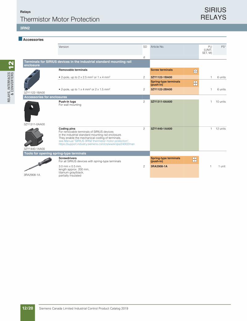
Terminals for SIRIUS devices in the industrial standard mounting rail enclosure
3ZY1122-1BA00
Removable terminals Screw terminals
2²mm4x1 ro ²mm 5.2x2 ot pu ,elop-2• 3ZY1122-1BA00 1 6 units
Spring-type terminals (push-in)
2²mm5.1x2 ro ²mm 4x1 ot pu ,elop-2• 3ZY1122-2BA00 1 6 units
Accessories for enclosures
3ZY1311-0AA00
Push-in lugsFor wall mounting
2 3ZY1311-0AA00 1 10 units
3ZY1440-1AA00
Coding pinsFor removable terminals of SIRIUS devicesin the industrial standard mounting rail enclosure.They enable the mechanical coding of terminals,see Manual "SIRIUS 3RN2 thermistor motor protection", https://support.industry.siemens.com/cs/ww/en/ps/24302/man
2 3ZY1440-1AA00 1 12 units
Tools for opening spring-type terminals
3RA2908-1A
Screwdrivers For all SIRIUS devices with spring-type terminals
Spring-type terminals (push-in)
3.0 mm x 0.5 mm, length approx. 200 mm,titanium gray/black,partially insulated
2 3RA2908-1A 1 1 unit
IC10_10_13.fm Page 165 Tuesday, March 13, 2018 12:45 PM

SIRIUS RELAYS
Siemens Canada Limited Industrial Control Product Catalog 2019 12/21
12
RELAYS, IN
TERFACES
& CO
NVERTERS
Siemens / Industrial Controls Previous folio: IC10 11/20
10/39Siemens IC 10 · 2016
RelaysTiming Relays
General data
10
Overview
7PV15, SIRIUS 3RP25 and SIRIUS 3RP20 timing relays
Electronic timing relays are used in control, starting, and protec-tive circuits for all switching operations involving time delays. Their fully developed concept and space-saving, compact de-sign make the SIRIUS 3RP timing relays ideal modules for con-trol cabinet, switchgear and control manufacturers in the industry.
With their narrow design, the 7PV15 timing relays are ideal in particular for use in heating, ventilation and air-conditioning systems and in compressors. All 7PV15 timing relays in this enclosure version are suitable for snap-on mounting onto TH 35 standard mounting rails according to IEC 60175. The enclosure complies with DIN 43880.
Benefits
• Clear-cut basic range with five basic units in the case of the 7PV15 timing relays, and seven basic units in the case of the 3RP timing relays
• Logistic advantages provided by versions with wide voltage range and wire setting range
• No tools required for assembly or disassembly on standard mounting rails
• Cadmium-free relay contacts• Recyclable, halogen-free enclosure• Optimum price/performance ratio• Versions with logical separation• Low variance: One design for distribution boards and for con-
trol cabinets• Compliance with EMC requirements for buildings• Environmentally friendly laser inscription instead of printing
containing solvents• Timing relays suitable for the 3RT miniature contactors allow
smaller tier spacing• Versions with screw terminals or alternatively with spring-type
terminals
Application
Timing relays with ON-delay• Interference pulse suppression (gating of interference pulses)• Gradual startup of motors so as not to overload the power
supply
Timing relays with OFF-delay• Generation of overtravel functions following removal of voltage • Gradual, delayed shutdown, e.g. of motors or fans, to allow a
plant to be shut down selectively
Wye-delta timing relay• Switchover of motors from wye to delta with a dead interval of
50 ms to prevent phase-to-phase short circuits
Multifunctional timing relays• Maximum flexibility, with a device for every application• Available with relay and semiconductor output
IC10_10_05.fm Page 39 Tuesday, June 14, 2016 12:08 PM
Function Relays, Interfaces and Converters
Timing Relays3RP25 / 3RP20 / 7PV15
SIRIUS RELAYS
Siemens Canada Limited Industrial Control Product Catalog 201912/22
12
RELA
YS, I
NTE
RFA
CES
& C
ON
VERT
ERS
Siemens / Industrial Controls Previous folio: IC10 11/21
10/40 Siemens IC 10 · 2016
RelaysTiming Relays
SIRIUS 3RP25 timing relays, 17.5 mm and 22.5 mm
10
Overview
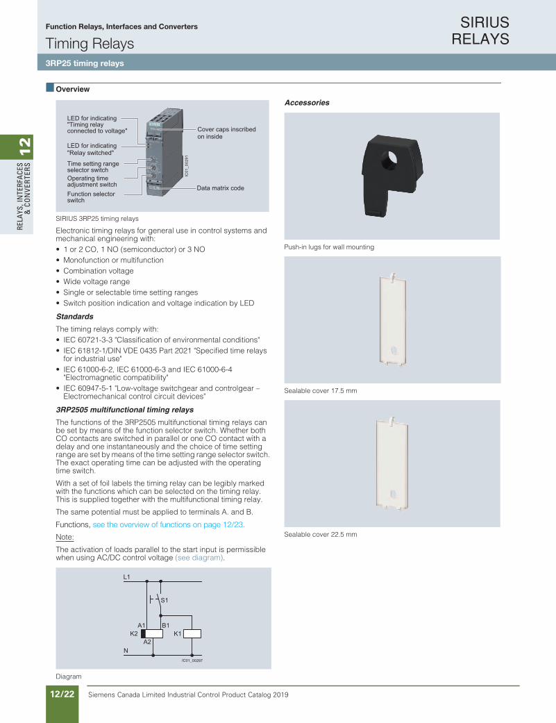
SIRIUS 3RP25 timing relays
Electronic timing relays for general use in control systems and mechanical engineering with:• 1 or 2 CO, 1 NO (semiconductor) or 3 NO• Monofunction or multifunction• Combination voltage• Wide voltage range• Single or selectable time setting ranges• Switch position indication and voltage indication by LED
Standards
The timing relays comply with: • IEC 60721-3-3 "Classification of environmental conditions"• IEC 61812-1/DIN VDE 0435 Part 2021 "Specified time relays
for industrial use"• IEC 61000-6-2, IEC 61000-6-3 and IEC 61000-6-4
"Electromagnetic compatibility"• IEC 60947-5-1 "Low-voltage switchgear and controlgear –
Electromechanical control circuit devices"
3RP2505 multifunctional timing relays
The functions of the 3RP2505 multifunctional timing relays can be set by means of the function selector switch. Whether both CO contacts are switched in parallel or one CO contact with a delay and one instantaneously and the choice of time setting range are set by means of the time setting range selector switch. The exact operating time can be adjusted with the operating time switch.
With a set of foil labels the timing relay can be legibly marked with the functions which can be selected on the timing relay. This is supplied together with the multifunctional timing relay.
The same potential must be applied to terminals A. and B.
Functions, see the overview of functions on page 10/41.
Note:
The activation of loads parallel to the start input is permissible when using AC/DC control voltage (see diagram).
Diagram
Accessories
Push-in lugs for wall mounting
Sealable cover 17.5 mm
Sealable cover 22.5 mm
LED for indicating"Timing relay connected to voltage"
LED for indicating"Relay switched"
Time setting range selector switch
Cover caps inscribed on inside
Data matrix codeOperating time adjustment switchFunction selector switch
IC01
_002
91
IC01_00297
K2A1
A2N
L1
S1
K1B1
IC10_10_05.fm Page 40 Tuesday, June 14, 2016 12:08 PM
Functions, see the overview of functions on page 12/23.
Function Relays, Interfaces and Converters
Timing Relays3RP25 timing relays

SIRIUS RELAYS
Siemens Canada Limited Industrial Control Product Catalog 2019 12/23
12
RELAYS, IN
TERFACES
& CO
NVERTERS
Siemens / Industrial Controls Previous folio: IC10 11/22
10/41Siemens IC 10 · 2016
RelaysTiming Relays
SIRIUS 3RP25 timing relays, 17.5 mm and 22.5 mm
10
Setting the functions on the device
Overview of functions of the 3RP2505 multifunctional timing relay
Note:
Conversion tool e.g. from 3RP15 to 3RP25, seewww.siemens.com/sirius/conversion-tool.
Two setting options for implementing the multifunctions (A-M):
Extended function variance by selecting the time range and determining, whether 2 CO switch in parallel or whether 1 CO switches with delay + 1 CO switches immediately (1 CO + 1 CO)
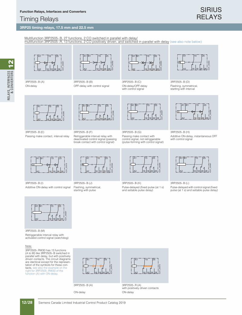
Determination of 13 functions by the setting A to M, with 1 CO, 1 NO, 2 CO that switch in parallel.
2
1
1
2
IC01
_003
53
Identification letter 13 functions 27 functions
1 CO, 1 NO (semiconductor) or 2 CO switched in parallel
13 functions (A - M) 2 CO switched in parallel + 13 functions (A - M) 1 CO delayed + 1 CO instantaneous (1 CO + 1 CO) and wye-delta function
A ON-delay ON-delay and instantaneous contact
B OFF-delay with control signal OFF-delay with control signal and instantaneous contact
C ON-delay/OFF-delay with control signal ON-delay/OFF-delay with control signal and instantaneous contact
D Flashing, symmetrical, starting with interval Flashing, symmetrical, starting with interval and instantaneouscontact
E Passing make contact, interval relay Passing make contact, interval relay and instantaneous contact
F Retriggerable interval relay with deactivated control signal(passing break contact with control signal)
Retriggerable interval relay with deactivated control signal (passing break contact with control signal) and instantaneous contact
G Passing make contact, with control signal, not retriggerable(pulse-forming with control signal)
Passing make contact, with control signal, not retriggerable(pulse-forming with control signal) and instantaneous contact
H Additive ON-delay, instantaneous OFF with control signal Additive ON-delay, instantaneous OFF with control signal and instantaneous contact
I Additive ON-delay with control signal Additive ON-delay with control signal and instantaneous contact
J Flashing, symmetrical, starting with pulse Flashing, symmetrical, starting with pulse and instantaneous contact
K Pulse-delayed (fixed pulse (at 1 s) and settable pulse delay) Pulse-delayed (fixed pulse (at 1 s) and settable pulse delay) and instantaneous contact
L Pulse-delayed with control signal (fixed pulse (at 1 s) and settable pulse delay)
Pulse-delayed with control signal (fixed pulse (at 1 s) and settable pulse delay) and instantaneous contact
M Retriggerable interval relay with activated control signal (watchdog) Retriggerable interval relay with activated control signal andinstantaneous contact (watchdog)
-- -- Wye-delta function
IC10_10_05.fm Page 41 Tuesday, June 14, 2016 12:08 PM
Function Relays, Interfaces and Converters
Timing Relays3RP25 timing relays, 17.5 mm and 22.5 mm

SIRIUS RELAYS
Siemens Canada Limited Industrial Control Product Catalog 201912/24
12
RELA
YS, I
NTE
RFA
CES
& C
ON
VERT
ERS
Siemens / Industrial Controls Previous folio: Siemens / Industrial Controls Previous folio: IC10 11/23
10/42 Siemens IC 10 · 2016
RelaysTiming Relays
SIRIUS 3RP25 timing relays, 17.5 mm and 22.5 mm
10
Article No. scheme
Note:
The Article No. scheme is presented here merely for information purposes and for better understanding of the logic behind the article numbers.
For your orders, please use the article numbers quoted in the catalog in the Selection and ordering data.
Benefits
• Easy stock keeping and logistics thanks to low variance of devices
• Reduced space requirement in the control cabinet thanks to variants in width 17.5 mm and 22 mm
• Consistent for all functions thanks to wide voltage range from 12 to 240 V AC/DC
• Up to 27 functions according to IEC 61812 in the multifunc-tional timing relay with wide voltage range
• Multifunctional timing relay with semiconductor output for high switching frequencies, bounce-free and wear-free switching
Application
Timing relays are used in control, starting, and protective circuits for all switching operations involving time delays. They guaran-tee a high level of functionality and a high repeat accuracy of timer settings.
Enclosure version
All timing relays are suitable for snap-on mounting onto TH 35 standard mounting rails according to IEC 60715 or for screw fixing.
Digit of the Article No. 1st - 5th 6th 7th 8th 9th 10th 11th 12th
@@@@@ @ @ – @ @ @ @ 0
Timing relays in industrial enclosure 17.5 mmand 22.5 mm
3 R P 25
Functions/time setting ranges @ @Connection type @Contacts @Rated control supply voltage @ @Example 3 R P 25 0 5 – 1 A W 3 0
IC10_10_05.fm Page 42 Tuesday, June 14, 2016 12:08 PM
Function Relays, Interfaces and Converters
Timing Relays3RP25 timing relays, 17.5 mm and 22.5 mm

SIRIUS RELAYS
Siemens Canada Limited Industrial Control Product Catalog 2019 12/25
12
RELAYS, IN
TERFACES
& CO
NVERTERS
Siemens / Industrial Controls Previous folio: Siemens / Industrial Controls Previous folio: IC10 11/24
10/43Siemens IC 10 · 2016
RelaysTiming Relays
SIRIUS 3RP25 timing relays, 17.5 mm and 22.5 mm
10
Technical specifications
Type 3RP2505-.A,3RP2505-.C,3RP251.,3RP2525-.A,3RP2527,3RP253.,3RP255.
3RP2505-.B,3RP2505-.R,3RP2525-.B,3RP254.,3RP256.,3RP257.
Width mm 17.5 22.5
Height mm 100 100
Depth mm 90 90
W
H
D
Type 3RP25..-.AB30,3RP25..-.AW30,3RP25..-.BB30,3RP25..-.BW30,3RP25..-.NW30,3RP25..-.SW30
3RP25..-.BT20,3RP25..-.NM20
3RP25..-.CW30 3RP25..-.EW30 3RP25..-.RW30
Insulation voltageFor overvoltage category III According to IEC 60664For pollution degree 3, rated value
V AC 300 500 300 -- 300
Ambient temperature• During operation °C -25 ... +60 -40 ... +70• During storage °C -40 ... +85
Operating range factorOf the control supply voltage, rated value• At AC
- At 50 Hz 0.85 ... 1.1 0.7 ... 1.1- At 60 Hz 0.85 ... 1.1 0.7 ... 1.1
• At DC 0.85 ... 1.1 -- 0.85 ... 1.1 0.85 ... 1.1 0.7 ... 1.1
Switching capacity currentWith inductive load
A 0.01 ... 3 0.01 ... 3 0.01 ... 1 0.01 ... 6 0.01 ... 3
Operational current of theauxiliary contacts
• At AC-15 - At 24 V A 3 3 1 -- 3- At 250 V A 3 3 1 -- 3- At 400 V A -- 3 -- -- --
• At DC-12 - At 24 V A -- -- 1 -- --- At 125 V A -- -- 1 -- --- At 250 V A -- -- 1 -- --
• At DC-13 - At 24 V A 1 1 -- -- 1- At 125 V A 0.2 0.2 -- -- 0.2- At 250 V A 0.1 0.1 -- -- 0.1
Uninterrupted thermal current Ith A 5 5 1 0.6 5
Mechanical endurance (Oper-ating cycles)Typical
10 x 106
Electrical endurance For AC-15 at 230 V, typical
(Oper-ating cycles)
1 x 10⁵
Type 3RP25
Connection type Screw terminals
• Design of thread of connection screw M3
• Solid mm2 1 x (0.5 ... 4.0)/2 x (0.5 ... 2.5)
• Finely stranded with end sleeve mm2 1 x (0.5 ... 4)/2 x (0.5 ... 1.5)
• Solid for AWG cables AWG 1 x (20 ... 12), 2 x (20 ... 14)
• Stranded for AWG cables AWG 1 x (20 ... 12), 2 x (20 ... 14)
• Tightening torque Nm 0.6 … 0.8
Connection type Spring-type terminals
• Solid mm2 1 x (0.5 ... 4)
• Finely stranded with end sleeve mm2 1 x (0.5 ... 2.5)
• AWG cables, solid AWG 1 x (20 ... 12)
• AWG cables, stranded AWG --
IC10_10_05.fm Page 43 Tuesday, June 14, 2016 12:08 PM
Function Relays, Interfaces and Converters
Timing Relays3RP25 timing relays, 17.5 mm and 22.5 mm
SIRIUS RELAYS
Siemens Canada Limited Industrial Control Product Catalog 201912/26
12
RELA
YS, I
NTE
RFA
CES
& C
ON
VERT
ERS
Siemens / Industrial Controls Previous folio: Siemens / Industrial Controls Previous folio: IC10 11/25
10/44 Siemens IC 10 · 2016
RelaysTiming Relays
SIRIUS 3RP25 timing relays, 17.5 mm and 22.5 mm
10
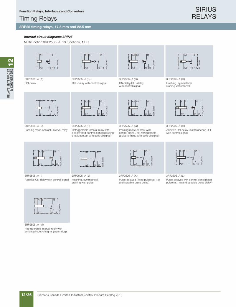
Internal circuit diagrams 3RP25
Multifunction 3RP2505-.A, 13 functions, 1 CO
3RP2505-.A (A) 3RP2505-.A (B) 3RP2505-.A (C) 3RP2505-.A (D)
ON-delay OFF-delay with control signal ON-delay/OFF-delaywith control signal
Flashing, symmetrical, starting with interval
3RP2505-.A (E) 3RP2505-.A (F) 3RP2505-.A (G) 3RP2505-.A (H)
Passing make contact, interval relay Retriggerable interval relay with deactivated control signal (passing break contact with control signal)
Passing make contact with control signal, not retriggerable (pulse-forming with control signal)
Additive ON-delay, instantaneous OFF with control signal
3RP2505-.A (I) 3RP2505-.A (J) 3RP2505-.A (K) 3RP2505-.A (L)
Additive ON-delay with control signal Flashing, symmetrical, starting with pulse
Pulse-delayed (fixed pulse (at 1 s) and settable pulse delay)
Pulse-delayed with control signal (fixed pulse (at 1 s) and settable pulse delay)
3RP2505-.A (M)
Retriggerable interval relay with activated control signal (watchdog)
A1
16 IC01
_002
96
18A2
15
16 IC01
_002
98
18
15A1 B1
A2
A1 B1
16 IC01
_002
99
18A2
15
~
A1
16 IC01
_003
00
18A2
15
A1
16 IC01
_003
01
18A2
15 A1 B1
16 IC01
_003
02
18A2
15 A1 B1
16 IC01
_003
03
18A2
15
16 IC01
_003
04
18
15A1 B1
A2
16 IC01
_003
04
18
15A1 B1
A2
~
A1
16 IC01
_003
05
18A2
15 A1
16 IC01
_003
01
18A2
15 A1 B1
16 IC01
_003
03
18A2
15
A1 B1
16 IC01
_003
03
18A2
15
IC10_10_05.fm Page 44 Tuesday, June 14, 2016 12:08 PM
Function Relays, Interfaces and Converters
Timing Relays3RP25 timing relays, 17.5 mm and 22.5 mm
SIRIUS RELAYS
Siemens Canada Limited Industrial Control Product Catalog 2019 12/27
12
RELAYS, IN
TERFACES
& CO
NVERTERS
Siemens / Industrial Controls Previous folio: IC10 11/26
10/45Siemens IC 10 · 2016
RelaysTiming Relays
SIRIUS 3RP25 timing relays, 17.5 mm and 22.5 mm
10
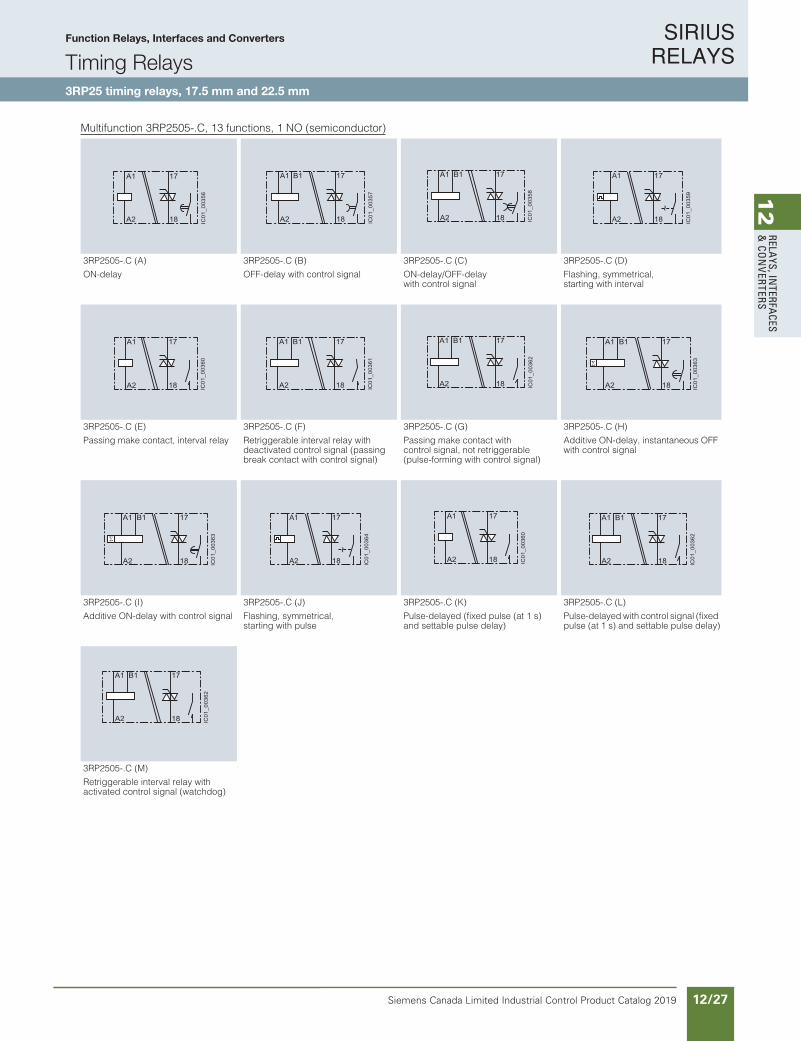
Multifunction 3RP2505-.C, 13 functions, 1 NO (semiconductor)
3RP2505-.C (A) 3RP2505-.C (B) 3RP2505-.C (C) 3RP2505-.C (D)
ON-delay OFF-delay with control signal ON-delay/OFF-delaywith control signal
Flashing, symmetrical, starting with interval
3RP2505-.C (E) 3RP2505-.C (F) 3RP2505-.C (G) 3RP2505-.C (H)
Passing make contact, interval relay Retriggerable interval relay with deactivated control signal (passing break contact with control signal)
Passing make contact with control signal, not retriggerable (pulse-forming with control signal)
Additive ON-delay, instantaneous OFF with control signal
3RP2505-.C (I) 3RP2505-.C (J) 3RP2505-.C (K) 3RP2505-.C (L)
Additive ON-delay with control signal Flashing, symmetrical,starting with pulse
Pulse-delayed (fixed pulse (at 1 s) and settable pulse delay)
Pulse-delayed with control signal (fixed pulse (at 1 s) and settable pulse delay)
3RP2505-.C (M)
Retriggerable interval relay with activated control signal (watchdog)
A1
IC01
_003
56
18A2
17
IC01
_003
57
A1
18A2
17B1 A1 B1
IC01
_003
58
A2 18
17
~
A1
IC01
_003
59
A2 18
17
A1
IC01
_003
60
A2 18
17 A1 B1
IC01
_003
61
A2 18
17 A1 B1
IC01
_003
62
A2 18
17 A1 B1
IC01
_003
63
A2 18
17
A1 B1
IC01
_003
63
A2 18
17 A1
IC01
_003
64
A2
~
18
17 A1IC
01_0
0360
A2 18
17 A1 B1
IC01
_003
62
A2 18
17
A1 B1
IC01
_003
62
A2 18
17
IC10_10_05.fm Page 45 Tuesday, June 14, 2016 12:08 PM
Function Relays, Interfaces and Converters
Timing Relays3RP25 timing relays, 17.5 mm and 22.5 mm
SIRIUS RELAYS
Siemens Canada Limited Industrial Control Product Catalog 201912/28
12
RELA
YS, I
NTE
RFA
CES
& C
ON
VERT
ERS
Siemens / Industrial Controls Previous folio: IC10 11/27
10/46 Siemens IC 10 · 2016
RelaysTiming Relays
SIRIUS 3RP25 timing relays, 17.5 mm and 22.5 mm
10
Multifunction 3RP2505-.B, 27 functions, 2 CO switched in parallel with delay/multifunction 3RP2505-.R, 13 functions, 2 CO positively driven, and switched in parallel with delay (see also note below)
3RP2505-.B (A) 3RP2505-.B (B) 3RP2505-.B (C) 3RP2505-.B (D)
ON-delay OFF-delay with control signal ON-delay/OFF-delaywith control signal
Flashing, symmetrical, starting with interval
3RP2505-.B (E) 3RP2505-.B (F) 3RP2505-.B (G) 3RP2505-.B (H)
Passing make contact, interval relay Retriggerable interval relay with deactivated control signal (passing break contact with control signal)
Passing make contact with control signal, not retriggerable (pulse-forming with control signal)
Additive ON-delay, instantaneous OFF with control signal
3RP2505-.B (I) 3RP2505-.B (J) 3RP2505-.B (K) 3RP2505-.B (L)
Additive ON-delay with control signal Flashing, symmetrical, starting with pulse
Pulse-delayed (fixed pulse (at 1 s) and settable pulse delay)
Pulse-delayed with control signal (fixed pulse (at 1 s) and settable pulse delay)
3RP2505-.B (M)
Retriggerable interval relay with activated control signal (watchdog)
Note:
3RP2505-.RW30 has 13 functions(A to M) like 3RP2505-.B switched in parallel with delay, but with positively driven contacts. The circuit diagrams are identical except for the represen-tation of the symbols for these con-tacts, see also the example on the right for 3RP2505-.RW30 of the function (A) with ON-delay.
3RP2505-.B (A) 3RP2505-.R (A) with positively driven contacts
ON-delay ON-delay
A1
16 IC01
_003
91
18A2
15
26 28
25
16 IC01
_003
92
18
15
26 28
25A1 B1
A2 16 IC01
_003
93
18
15
26 28
25A1 B1
A2
~
A1
16 IC01
_003
94
18A2
15
26 28
25
A1
16 IC01
_003
95
18A2
15
26 28
25
16 IC01
_003
96
18
15
26 28
25A1 B1
A2 16 IC01
_003
97
18
15
26 28
25A1 B1
A2 16 IC01
_003
98
18
15
26 28
25A1 B1
A2
A1
16 IC01
_003
78
18A2
15
26 28
25B1
~
A1
16 IC01
_003
94
18A2
15
26 28
25 A1
16 IC01
_003
95
18A2
15
26 28
25
16 IC01
_003
97
18
15
26 28
25A1 B1
A2
16 IC01
_003
97
18
15
26 28
25A1 B1
A2
A1
16 IC01
_004
79
18A2
15
26 28
25 A1
16 IC01
_004
75
18A2
15
26 28
25
IC10_10_05.fm Page 46 Tuesday, June 14, 2016 12:08 PM
Function Relays, Interfaces and Converters
Timing Relays3RP25 timing relays, 17.5 mm and 22.5 mm

SIRIUS RELAYS
Siemens Canada Limited Industrial Control Product Catalog 2019 12/29
12
RELAYS, IN
TERFACES
& CO
NVERTERS
Siemens / Industrial Controls Previous folio: IC10 11/28
10/47Siemens IC 10 · 2016
RelaysTiming Relays
SIRIUS 3RP25 timing relays, 17.5 mm and 22.5 mm
10
Multifunction 3RP2505-.B, 27 functions, 1 CO delayed + 1 CO instantaneous (continued)
3RP2505-.B (A) 3RP2505-.B (B) 3RP2505-.B (C) 3RP2505-.B (D)
ON-delay and instantaneous contact OFF-delay with control signal and instantaneous contact
ON-delay/OFF-delay with control signal and instantaneous contact
Flashing, symmetrical, starting with interval and instantaneous contact
3RP2505-.B (E) 3RP2505-.B (F) 3RP2505-.B (G) 3RP2505-.B (H)
Passing make contact, interval relay and instantaneous contact
Retriggerable interval relay with deactivated control signal (passing break contact with control signal) and instantaneous contact
Passing make contact with control signal, not retriggerable (pulse-forming with control signal) and instantaneous contact
Additive ON-delay, instantaneous OFF with control signal and instantaneous contact
3RP2505-.B (I) 3RP2505-.B (J) 3RP2505-.B (K) 3RP2505-.B (L)
Additive ON-delay with control signal and instantaneous contact
Flashing, symmetrical, starting with pulse and instantaneous contact
Pulse-delayed (fixed pulse (at 1 s) and settable pulse delay) and instantaneous contact
Pulse-delayed with control signal (fixed pulse (at 1 s) and settable pulse delay) and instantaneous contact
3RP2505-.B (M) 3RP2505-.B
Retriggerable interval relay withactivated control signal andinstantaneous contact (watchdog)
Wye-delta function
A1
16 IC01
_003
65
18A2
15
22 24
21
16 IC01
_003
66
18
15
22 24
21A1 B1
A2
A1 B1
16 IC01
_003
67
18A2
15
22 24
21
~
A1
16 IC01
_003
68
18A2
15
22 24
21
A1
16 IC01
_003
69
18A2
15
22 24
21 A1 B1
16 IC01
_003
70
18A2
15
22 24
21 A1 B1
16 IC01
_003
71
18A2
15
22 24
21 A1
16 IC01
_003
72
18A2
15
22 24
21B1
A1
16 IC01
_003
72
18A2
15
22 24
21B1
~
A1
16 IC01
_003
73
18A2
15
22 24
21 A1
16 IC01
_003
69
18A2
15
22 24
21 A1 B1
16 IC01
_003
71
18A2
15
22 24
21
A1 B1
16 IC01
_003
71
18A2
15
22 24
21A1
IC01
_003
79
A2 16 18
15
26 28
25
IC10_10_05.fm Page 47 Tuesday, June 14, 2016 12:08 PM
Function Relays, Interfaces and Converters
Timing Relays3RP25 timing relays, 17.5 mm and 22.5 mm
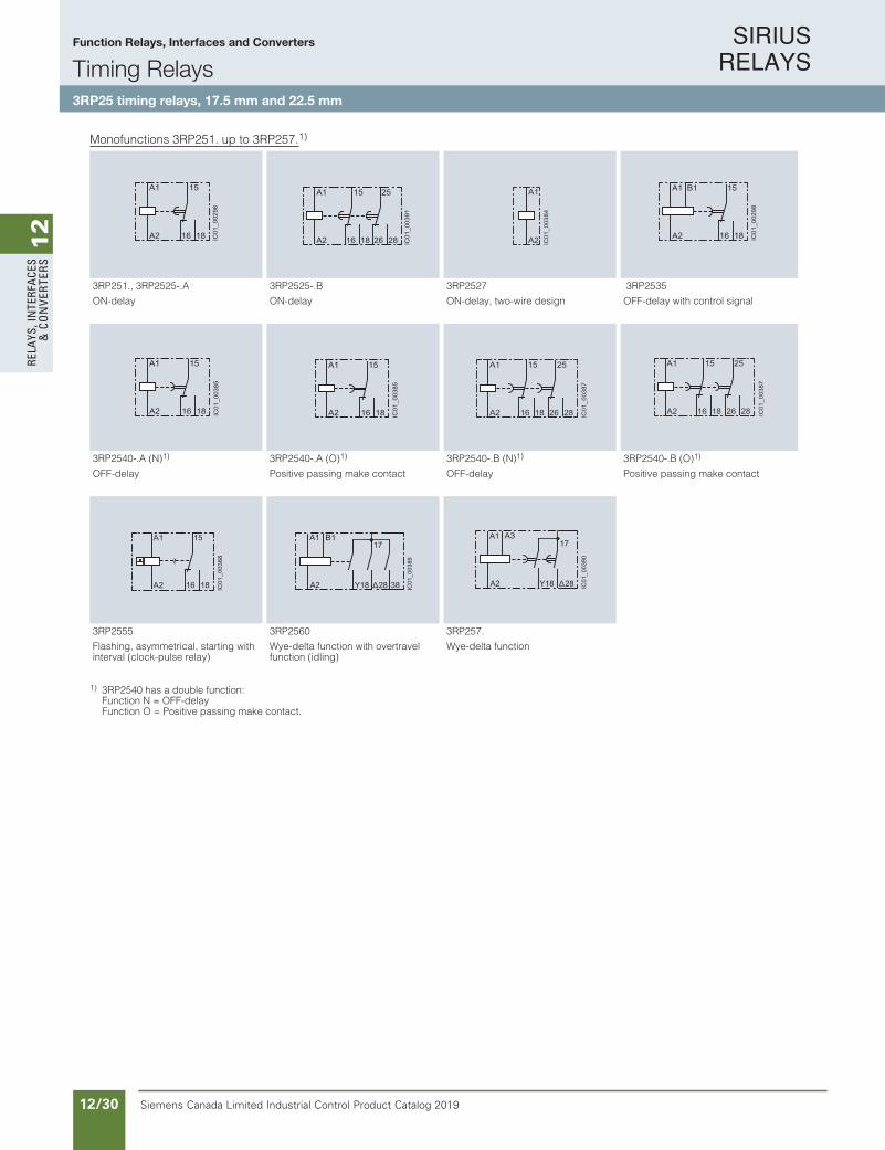
SIRIUS RELAYS
Siemens Canada Limited Industrial Control Product Catalog 201912/30
12
RELA
YS, I
NTE
RFA
CES
& C
ON
VERT
ERS
Siemens / Industrial Controls Previous folio: IC10 11/29
10/48 Siemens IC 10 · 2016
RelaysTiming Relays
SIRIUS 3RP25 timing relays, 17.5 mm and 22.5 mm
10
Monofunctions 3RP251. up to 3RP257.1)
1) 3RP2540 has a double function:Function N = OFF-delayFunction O = Positive passing make contact.
3RP251., 3RP2525-.A 3RP2525-.B 3RP2527 3RP2535
ON-delay ON-delay ON-delay, two-wire design OFF-delay with control signal
3RP2540-.A (N)1) 3RP2540-.A (O)1) 3RP2540-.B (N)1) 3RP2540-.B (O)1)
OFF-delay Positive passing make contact OFF-delay Positive passing make contact
3RP2555 3RP2560 3RP257.
Flashing, asymmetrical, starting with interval (clock-pulse relay)
Wye-delta function with overtravel function (idling)
Wye-delta function
A1
16 IC01
_002
96
18A2
15 A1
16 IC01
_003
91
18A2
15
26 28
25 A1
IC01
_003
84
A2 16 IC01
_002
98
18
15A1 B1
A2
16 IC01
_003
85
18
15A1
A2 16 IC01
_003
85
18
15A1
A2
A1
16 IC01
_003
87
18
15
26 28
25
A2
A1
16 IC01
_003
87
18
15
26 28
25
A2
~
16 IC01
_003
88
18
15A1
A2 Y18 28 IC01
_003
89
17A1
A2 38
B1
Y18 28 IC01
_003
90
17A1
A2
A3
IC10_10_05.fm Page 48 Tuesday, June 14, 2016 12:08 PM
Function Relays, Interfaces and Converters
Timing Relays3RP25 timing relays, 17.5 mm and 22.5 mm
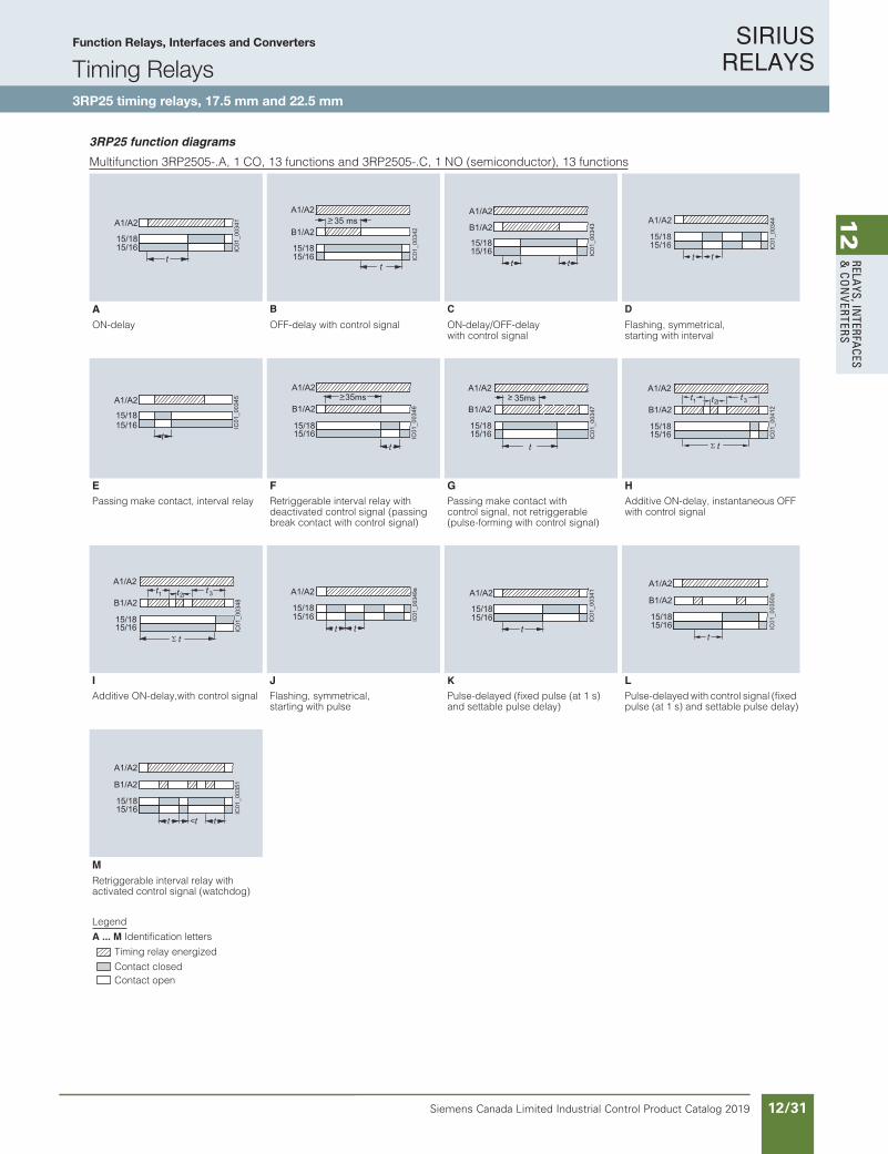
SIRIUS RELAYS
Siemens Canada Limited Industrial Control Product Catalog 2019 12/31
12
RELAYS, IN
TERFACES
& CO
NVERTERS
10/49Siemens IC 10 · 2016
RelaysTiming Relays
SIRIUS 3RP25 timing relays, 17.5 mm and 22.5 mm
10
3RP25 function diagrams
Multifunction 3RP2505-.A, 1 CO, 13 functions and 3RP2505-.C, 1 NO (semiconductor), 13 functions
A B C D
ON-delay OFF-delay with control signal ON-delay/OFF-delay with control signal
Flashing, symmetrical,starting with interval
E F G H
Passing make contact, interval relay Retriggerable interval relay withdeactivated control signal (passing break contact with control signal)
Passing make contact withcontrol signal, not retriggerable (pulse-forming with control signal)
Additive ON-delay, instantaneous OFF with control signal
I J K L
Additive ON-delay,with control signal Flashing, symmetrical, starting with pulse
Pulse-delayed (fixed pulse (at 1 s) and settable pulse delay)
Pulse-delayed with control signal (fixed pulse (at 1 s) and settable pulse delay)
M Retriggerable interval relay withactivated control signal (watchdog)
Legend
A ... M Identification letters
Timing relay energized
Contact closedContact open
15/1815/16
A1/A2IC
01_0
0341
t
35 msB1/A2
15/1615/18
A1/A2>
IC01
_003
42
t
IC01
_003
43
t
B1/A2
A1/A2
t
15/1815/16 IC
01_0
0344A1/A2
t t15/1615/18
IC01
_003
45A1/A2
t15/1615/18
A1/A2
B1/A2>
IC01
_003
46
35ms
t15/1615/18
>
IC01
_003
47
35msB1/A2
A1/A2
t15/1615/18
2t 3t1
t
t
IC01
_004
12B1/A2
A1/A2
15/1615/18
2t 3t1
t
t
IC01
_003
48B1/A2
A1/A2
15/1615/18 IC
01_0
0349
a
t
A1/A2
t15/1615/18 15/18
15/16
A1/A2IC
01_0
0341
t 15/1615/18
A1/A2
IC01
_003
50a
t
B1/A2
15/1615/18
A1/A2
IC01
_003
51
t t<t
B1/A2
IC10_10_05.fm Page 49 Tuesday, June 14, 2016 12:08 PM
Function Relays, Interfaces and Converters
Timing Relays3RP25 timing relays, 17.5 mm and 22.5 mm
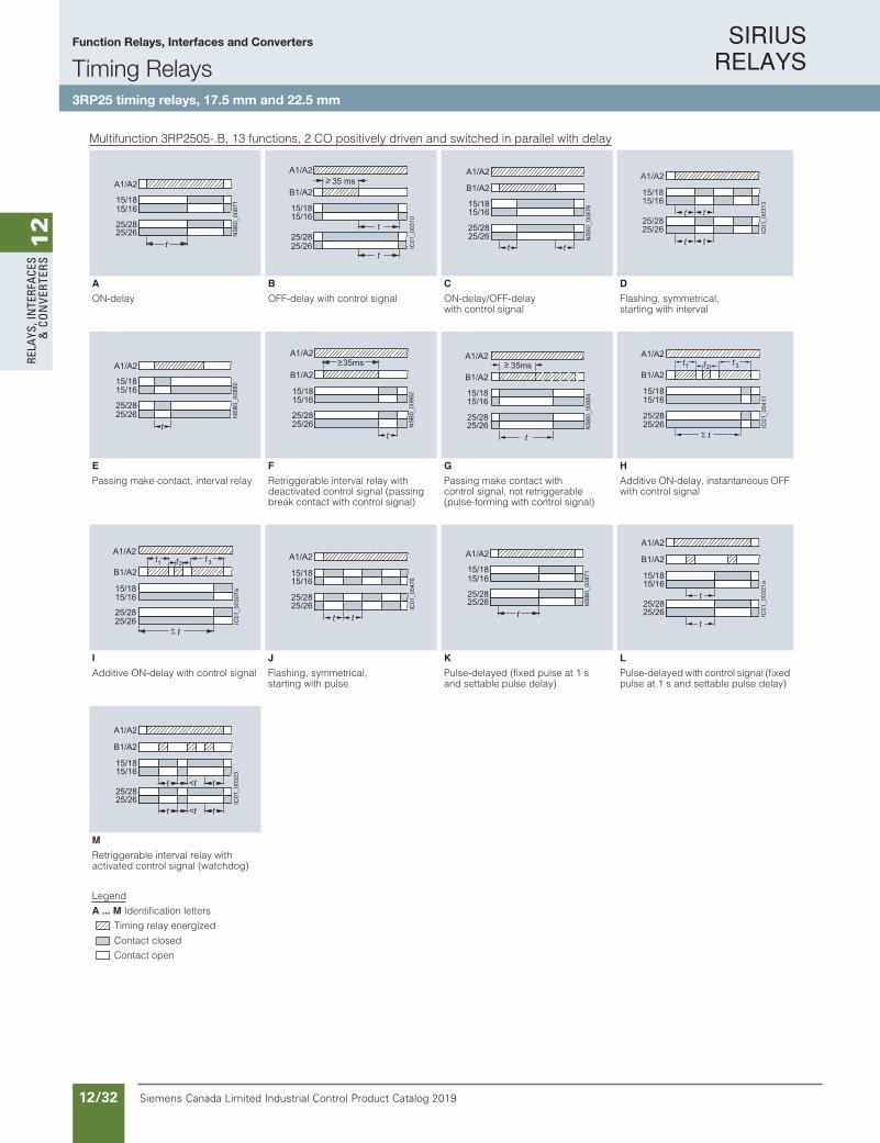
SIRIUS RELAYS
Siemens Canada Limited Industrial Control Product Catalog 201912/32
12
RELA
YS, I
NTE
RFA
CES
& C
ON
VERT
ERS
10/50 Siemens IC 10 · 2016
RelaysTiming Relays
SIRIUS 3RP25 timing relays, 17.5 mm and 22.5 mm
10
Multifunction 3RP2505-.B, 13 functions, 2 CO positively driven and switched in parallel with delay
A B C D
ON-delay OFF-delay with control signal ON-delay/OFF-delay with control signal
Flashing, symmetrical, starting with interval
E F G H
Passing make contact, interval relay Retriggerable interval relay with deactivated control signal (passing break contact with control signal)
Passing make contact with control signal, not retriggerable (pulse-forming with control signal)
Additive ON-delay, instantaneous OFF with control signal
I J K L
Additive ON-delay with control signal Flashing, symmetrical, starting with pulse
Pulse-delayed (fixed pulse at 1 s and settable pulse delay)
Pulse-delayed with control signal (fixed pulse at 1 s and settable pulse delay)
M
Retriggerable interval relay with activated control signal (watchdog)
Legend
A ... M Identification letters
Timing relay energized
Contact closed
Contact open
25/2625/28
15/1615/18
A1/A2
NS
B0_
0087
1
t
35 ms
25/2625/28
B1/A2
15/1615/18
A1/A2>
IC01
_003
10
t
t
NS
B0_
0087
6
t
B1/A2
A1/A2
25/2625/28
t
15/1615/18
IC01
_003
13
t25/2625/28
A1/A2
t
t t15/1615/18
NS
B0_
0088
0
25/2625/28
A1/A2
t
15/1615/18
A1/A2
B1/A2
25/26
>
NS
B0_
0088
2
35ms
25/28
t
15/1615/18
>
NS
B0_
0088
4
35msB1/A2
A1/A2
25/2625/28
t
15/1615/18
2t 3t1
t
t
IC01
_004
11
B1/A2
A1/A2
25/2625/28
15/1615/18
2t 3t1
t
t
IC01
_003
07a
B1/A2
A1/A2
25/2625/28
15/1615/18
IC01
_004
76
t25/2625/28
A1/A2
t
15/1615/18
25/2625/28
15/1615/18
A1/A2
NS
B0_
0087
1
t 25/2625/28
15/1615/18
A1/A2
IC01
_003
21a
t
t
B1/A2
25/2625/28
15/1615/18
A1/A2
IC01
_003
23
t t<t
t t<t
B1/A2
IC10_10_05.fm Page 50 Tuesday, June 14, 2016 12:08 PM
Function Relays, Interfaces and Converters
Timing Relays3RP25 timing relays, 17.5 mm and 22.5 mm

SIRIUS RELAYS
Siemens Canada Limited Industrial Control Product Catalog 2019 12/33
12
RELAYS, IN
TERFACES
& CO
NVERTERS
10/51Siemens IC 10 · 2016
RelaysTiming Relays
SIRIUS 3RP25 timing relays, 17.5 mm and 22.5 mm
10
Multifunction 3RP2505-.B, 27 functions, 2 CO
A B2 CO switched in parallel 1 CO delayed +
1 CO instantaneous2 CO switched in parallel 1 CO delayed +
1 CO instantaneous
dna langis lortnoc htiw yaled-FFO langis lortnoc htiw yaled-FFOtcatnoc suoenatnatsni dna yaled-NOyaled-NOinstantaneous contact
C D2 CO switched in parallel 1 CO delayed +
1 CO instantaneous2 CO switched in parallel 1 CO delayed +
1 CO instantaneous
ON-delay/OFF-delaywith control signal
ON-delay/OFF-delay with control signal and instantaneous contact
Flashing, symmetrical, starting with interval
Flashing, symmetrical, starting with interval and instantaneous contact
E F2 CO switched in parallel 1 CO delayed +
1 CO instantaneous2 CO switched in parallel 1 CO delayed +
1 CO instantaneous
Passing make contact, interval relay Passing make contact, interval relay and instantaneous contact
Retriggerable interval relay with deactivated control signal (passing break contact with control signal)
Retriggerable interval relay with deactivated control signal (passing break contact with control signal)and instantaneous contact
G H2 CO switched in parallel 1 CO delayed +
1 CO instantaneous2 CO switched in parallel 1 CO delayed +
1 CO instantaneous
Passing make contact withcontrol signal, not retriggerable(pulse-forming with control signal)
Passing make contact with control signal, not retriggerable (pulse-forming with control signal) and instantaneous contact
Additive ON-delay, instantaneous OFF with control signal
Additive ON-delay, instantaneous OFF with control signal and instantaneous contact
Legend
A ... M Identification letters
Timing relay energized
Contact closed
Contact open
25/2625/28
15/1615/18
A1/A2N
SB
0_00
871
t 21/2221/24
IC01
_003
09
A1/A2
t15/1615/18
35 ms
25/2625/28
B1/A2
15/1615/18
A1/A2>
IC01
_003
10
t
t
>B1/A2
A1/A2
IC01
_003
11
21/2221/24
35ms
t15/1615/18
NS
B0_
0087
6
t
B1/A2
A1/A2
25/2625/28
t
15/1615/18
IC01
_003
12
t
B1/A2
A1/A2
21/2221/24
t15/1615/18
IC01
_003
13
t25/2625/28
A1/A2
t
t t15/1615/18
tt
A1/A2
IC01
_003
14
21/2221/24
15/1615/18
NS
B0_
0088
0
25/2625/28
A1/A2
t
15/1615/18
t
A1/A2
IC01
_003
15
21/2221/24
15/1615/18
A1/A2
B1/A2
25/26
>
NS
B0_
0088
2
35ms
25/28
t
15/1615/18
>B1/A2
A1/A2
IC01
_003
16
21/2221/24
35ms
t15/1615/18
>
NS
B0_
0088
4
35msB1/A2
A1/A2
25/2625/28
t
15/1615/18
>35ms
IC01
_003
17
t
B1/A2
A1/A2
21/2221/24
15/1615/18
2t 3t1
t
t
IC01
_004
11
B1/A2
A1/A2
25/2625/28
15/1615/18
t
2ttt1 3
B1/A2
A1/A2
21/2221/24
15/1615/18
IC01
_003
18
IC10_10_05.fm Page 51 Tuesday, June 14, 2016 12:08 PM
Function Relays, Interfaces and Converters
Timing Relays3RP25 timing relays, 17.5 mm and 22.5 mm

SIRIUS RELAYS
Siemens Canada Limited Industrial Control Product Catalog 201912/34
12
RELA
YS, I
NTE
RFA
CES
& C
ON
VERT
ERS
10/52 Siemens IC 10 · 2016
RelaysTiming Relays
SIRIUS 3RP25 timing relays, 17.5 mm and 22.5 mm
10
Multifunction 3RP2505-.B, 27 functions, 2 CO (continued)
I J
2 CO switched in parallel 1 CO delayed + 1 CO instantaneous
2 CO switched in parallel 1 CO delayed + 1 CO instantaneous
Additive ON-delay with control signal Additive ON-delay with control signal and instantaneous contact
Flashing, symmetrical, starting with pulse
Flashing, symmetrical, starting with pulse and instantaneous contact
K L
2 CO switched in parallel 1 CO delayed + 1 CO instantaneous
2 CO switched in parallel 1 CO delayed + 1 CO instantaneous
Pulse-delayed (fixed pulse at 1 s and settable pulse delay)
Pulse-delayed (fixed pulse at 1 s and settable pulse delay) andinstantaneous contact
Pulse-delayed with control signal (fixed pulse at 1 s and settable pulse delay)
Pulse-delayed with control signal(fixed pulse at 1 s and settable pulse delay) and instantaneous contact
M *2 CO switched in parallel 1 CO delayed +
1 CO instantaneous2 CO switched in parallel or 1 CO delayed + 1 CO instantaneous
Retriggerable interval relay with activated control signal (watchdog)
Retriggerable interval relay with activated control signal andinstantaneous contact (watchdog)
Wye-delta function
Legend
A ... M Identification letters
Timing relay energized
Contact closed
Contact open
2t 3t1
t
tIC
01_0
0307
aB1/A2
A1/A2
25/2625/28
15/1615/18
t
2ttt1 3
B1/A2
A1/A2
21/2221/24
15/1615/18
IC01
_003
06
IC01
_004
76
t25/2625/28
A1/A2
t
15/1615/18
tt
A1/A2
IC01
_003
19
21/2221/24
15/1615/18
25/2625/28
15/1615/18
A1/A2
NS
B0_
0087
1
t 21/2221/24
IC01
_003
20
A1/A2
t15/1615/18
25/2625/28
15/1615/18
A1/A2
IC01
_003
21a
t
t
B1/A2
21/2221/24
15/1615/18
A1/A2
IC01
_003
22
t
B1/A2
25/2625/28
15/1615/18
A1/A2
IC01
_003
23
t t<t
t t<t
B1/A2
21/2221/24
15/1615/18
A1/A2
IC01
_003
24
t t<t
B1/A2
IC01
_003
25
25/28
15/18
50ms
A1/A2
t
IC10_10_05.fm Page 52 Tuesday, June 14, 2016 12:08 PM
Function Relays, Interfaces and Converters
Timing Relays3RP25 timing relays, 17.5 mm and 22.5 mm
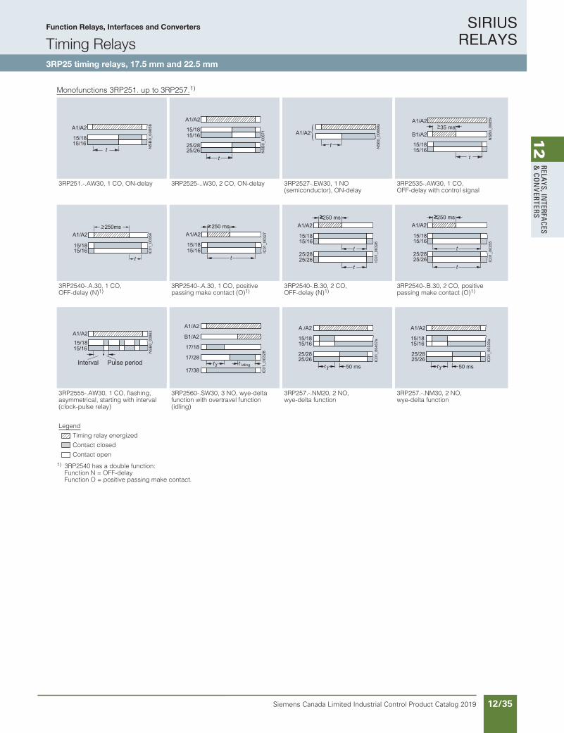
SIRIUS RELAYS
Siemens Canada Limited Industrial Control Product Catalog 2019 12/35
12
RELAYS, IN
TERFACES
& CO
NVERTERS
10/53Siemens IC 10 · 2016
RelaysTiming Relays
SIRIUS 3RP25 timing relays, 17.5 mm and 22.5 mm
10
Monofunctions 3RP251. up to 3RP257.1)
1) 3RP2540 has a double function:Function N = OFF-delayFunction O = positive passing make contact.
3RP251.-.AW30, 1 CO, ON-delay 3RP2525-..W30, 2 CO, ON-delay 3RP2527-.EW30, 1 NO (semiconductor), ON-delay
3RP2535-.AW30, 1 CO, OFF-delay with control signal
3RP2540-.A.30, 1 CO, OFF-delay (N)1)
3RP2540-.A.30, 1 CO, positive passing make contact (O)1)
3RP2540-.B.30, 2 CO, OFF-delay (N)1)
3RP2540-.B.30, 2 CO, positivepassing make contact (O)1)
3RP2555-.AW30, 1 CO, flashing, asymmetrical, starting with interval (clock-pulse relay)
3RP2560-.SW30, 3 NO, wye-delta function with overtravel function (idling)
3RP257.-.NM20, 2 NO, wye-delta function
3RP257.-.NM30, 2 NO, wye-delta function
Legend
Timing relay energized
Contact closed
Contact open
15/18
A1/A2
15/16N
SB
0_00
858
t 25/2625/28
15/1615/18
A1/A2
NS
B0_
0087
1
t
NS
B0_
0086
9a
A1/A2
t
>B1/A2
NS
B0_
0085
9
35 ms
t15/1615/18
A1/A2
A1/A2>
IC01
_003
54
250ms
t15/1615/18
IC01
_003
27
15/18
t
250 msA1/A2
15/16
IC01
_003
26
25/2625/28
15/18
t
t
250 msA1/A2
15/16
IC01
_003
55
25/2625/28
15/18
t
t
250 msA1/A2
15/16
NSB
0_00
863
15/16
A1/A2
15/18
Interval Pulse period
A1/A2
B1/A2
17/18
IC01
_003
28
17/28
17/38t Idlingt
15/1815/16
A./A2
IC01
_004
07a
50 mst25/2625/28
15/1815/16
A1/A2
IC01
_003
30a
50 mst25/2625/28
IC10_10_05.fm Page 53 Tuesday, June 14, 2016 12:08 PM
Function Relays, Interfaces and Converters
Timing Relays3RP25 timing relays, 17.5 mm and 22.5 mm
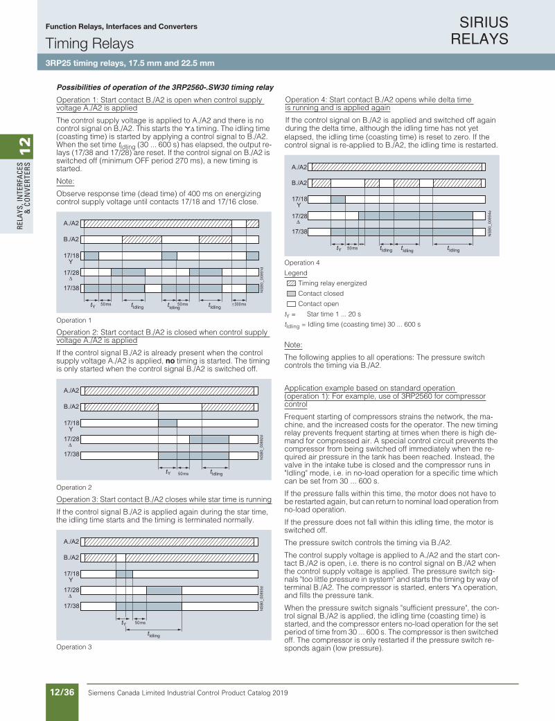
SIRIUS RELAYS
Siemens Canada Limited Industrial Control Product Catalog 201912/36
12
RELA
YS, I
NTE
RFA
CES
& C
ON
VERT
ERS
10/54 Siemens IC 10 · 2016
RelaysTiming Relays
SIRIUS 3RP25 timing relays, 17.5 mm and 22.5 mm
10
Possibilities of operation of the 3RP2560-.SW30 timing relayOperation 1: Start contact B./A2 is open when control supply voltage A./A2 is applied
The control supply voltage is applied to A./A2 and there is no control signal on B./A2. This starts the *∆ timing. The idling time (coasting time) is started by applying a control signal to B./A2. When the set time tIdling (30 ... 600 s) has elapsed, the output re-lays (17/38 and 17/28) are reset. If the control signal on B./A2 is switched off (minimum OFF period 270 ms), a new timing is started.
Note:
Observe response time (dead time) of 400 ms on energizing control supply voltage until contacts 17/18 and 17/16 close.
Operation 1
Operation 2: Start contact B./A2 is closed when control supply voltage A./A2 is applied
If the control signal B./A2 is already present when the control supply voltage A./A2 is applied, no timing is started. The timing is only started when the control signal B./A2 is switched off.
Operation 2
Operation 3: Start contact B./A2 closes while star time is running
If the control signal B./A2 is applied again during the star time, the idling time starts and the timing is terminated normally.
Operation 3
Operation 4: Start contact B./A2 opens while delta time is running and is applied again
If the control signal on B./A2 is applied and switched off again during the delta time, although the idling time has not yet elapsed, the idling time (coasting time) is reset to zero. If the control signal is re-applied to B./A2, the idling time is restarted.
Operation 4
Legend
Timing relay energized
Contact closed
Contact open
tY = Star time 1 ... 20 s
tIdling = Idling time (coasting time) 30 ... 600 s
Note:
The following applies to all operations: The pressure switch controls the timing via B./A2.
Application example based on standard operation (operation 1): For example, use of 3RP2560 for compressorcontrol
Frequent starting of compressors strains the network, the ma-chine, and the increased costs for the operator. The new timing relay prevents frequent starting at times when there is high de-mand for compressed air. A special control circuit prevents the compressor from being switched off immediately when the re-quired air pressure in the tank has been reached. Instead, the valve in the intake tube is closed and the compressor runs in "Idling" mode, i.e. in no-load operation for a specific time which can be set from 30 ... 600 s.
If the pressure falls within this time, the motor does not have to be restarted again, but can return to nominal load operation from no-load operation.
If the pressure does not fall within this idling time, the motor is switched off.
The pressure switch controls the timing via B./A2.
The control supply voltage is applied to A./A2 and the start con-tact B./A2 is open, i.e. there is no control signal on B./A2 when the control supply voltage is applied. The pressure switch sig-nals "too little pressure in system" and starts the timing by way of terminal B./A2. The compressor is started, enters *∆ operation, and fills the pressure tank.
When the pressure switch signals "sufficient pressure", the con-trol signal B./A2 is applied, the idling time (coasting time) is started, and the compressor enters no-load operation for the set period of time from 30 ... 600 s. The compressor is then switched off. The compressor is only restarted if the pressure switch re-sponds again (low pressure).
A./A2
B./A2
17/18 Y
17/28
17/38
Idlingt IdlingtIdlingt50 05sm ms 300 msYt
NS
B0_
0089
1d
A./A2
B./A2
17/18 Y17/28
17/38
NS
B0_
0089
2d
Yt Idlingt50 ms
A./A2
B./A2
17/18 Y17/28
17/38
NS
B0_
0089
3d
Idlingt
50 msYt
17/38
17/28
Y17/18
B./A2
A./A2
Idlingt IdlingtIdlingt50 msYt
NS
B0_
0089
4e
IC10_10_05.fm Page 54 Tuesday, June 14, 2016 12:08 PM
Function Relays, Interfaces and Converters
Timing Relays3RP25 timing relays, 17.5 mm and 22.5 mm
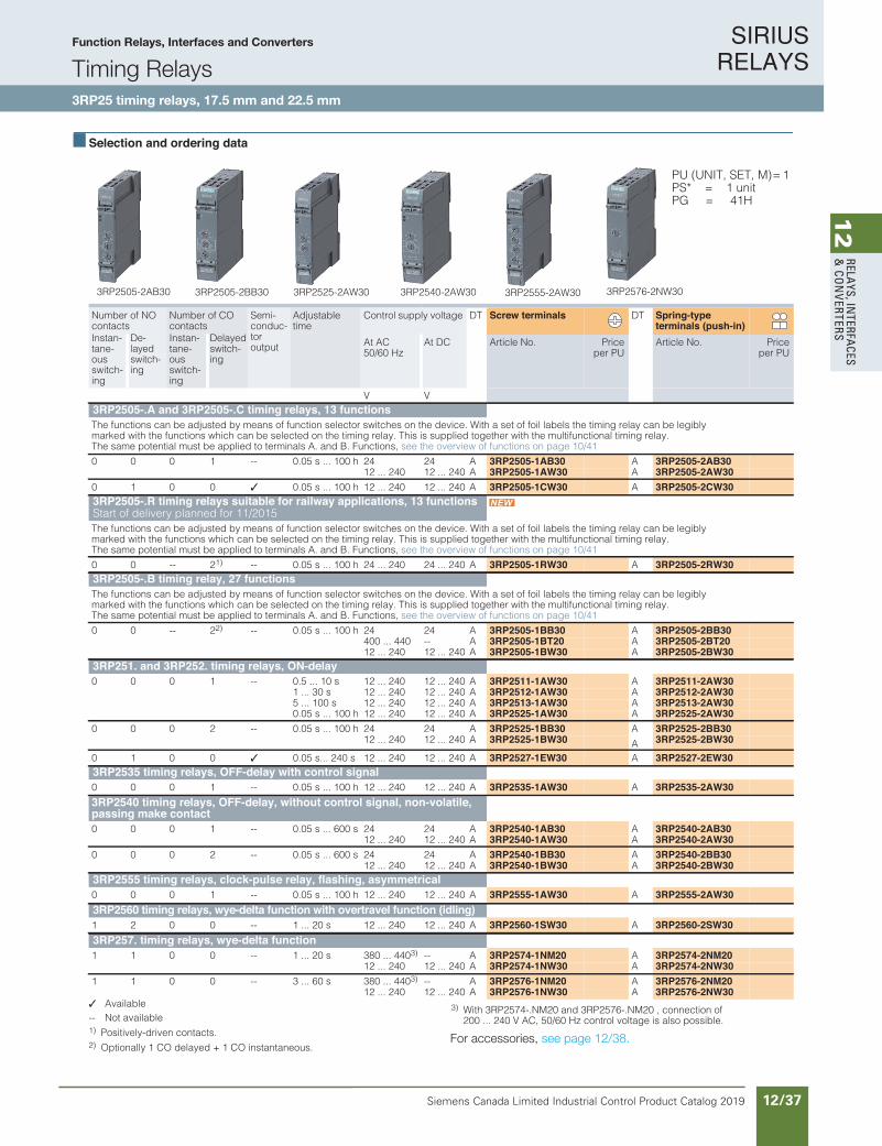
SIRIUS RELAYS
Siemens Canada Limited Industrial Control Product Catalog 2019 12/37
12
RELAYS, IN
TERFACES
& CO
NVERTERS
10/55Siemens IC 10 · 2016* You can order this quantity or a multiple thereof.Illustrations are approximate
RelaysTiming Relays
SIRIUS 3RP25 timing relays, 17.5 mm and 22.5 mm
10
Selection and ordering data
PU (UNIT, SET, M)= 1PS* = 1 unitPG = 41H
Available -- Not available1) Positively-driven contacts.2) Optionally 1 CO delayed + 1 CO instantaneous.
3) With 3RP2574-.NM20 and 3RP2576-.NM20 , connection of 200 ... 240 V AC, 50/60 Hz control voltage is also possible.
For accessories, see page 10/56.
Number of NO contacts
Number of CO contacts
Semi-conduc-toroutput
Adjustable time
Control supply voltage DT Screw terminals DT Spring-typeterminals (push-in)
Instan-tane-ous switch-ing
De-layed switch-ing
Instan-tane-ous switch-ing
Delayed switch-ing
At AC 50/60 Hz
At DC Article No. Priceper PU
Article No. Priceper PU
V V3RP2505-.A and 3RP2505-.C timing relays, 13 functionsThe functions can be adjusted by means of function selector switches on the device. With a set of foil labels the timing relay can be legibly marked with the functions which can be selected on the timing relay. This is supplied together with the multifunctional timing relay. The same potential must be applied to terminals A. and B. Functions, see the overview of functions on page 10/41
0 0 0 1 -- 0.05 s ... 100 h 24 24 A 3RP2505-1AB30 A 3RP2505-2AB3012 ... 240 12 ... 240 A 3RP2505-1AW30 A 3RP2505-2AW30
0 1 0 0 0.05 s ... 100 h 12 ... 240 12 ... 240 A 3RP2505-1CW30 A 3RP2505-2CW303RP2505-.R timing relays suitable for railway applications, 13 functionsStart of delivery planned for 11/2015The functions can be adjusted by means of function selector switches on the device. With a set of foil labels the timing relay can be legibly marked with the functions which can be selected on the timing relay. This is supplied together with the multifunctional timing relay. The same potential must be applied to terminals A. and B. Functions, see the overview of functions on page 10/41
0 0 -- 21) -- 0.05 s ... 100 h 24 ... 240 24 ... 240 A 3RP2505-1RW30 A 3RP2505-2RW303RP2505-.B timing relay, 27 functionsThe functions can be adjusted by means of function selector switches on the device. With a set of foil labels the timing relay can be legibly marked with the functions which can be selected on the timing relay. This is supplied together with the multifunctional timing relay. The same potential must be applied to terminals A. and B. Functions, see the overview of functions on page 10/41
0 0 -- 22) -- 0.05 s ... 100 h 24 24 A 3RP2505-1BB30 A 3RP2505-2BB30400 ... 440 -- A 3RP2505-1BT20 A 3RP2505-2BT2012 ... 240 12 ... 240 A 3RP2505-1BW30 A 3RP2505-2BW30
3RP251. and 3RP252. timing relays, ON-delay0 0 0 1 -- 0.5 ... 10 s 12 ... 240 12 ... 240 A 3RP2511-1AW30 A 3RP2511-2AW30
1 ... 30 s 12 ... 240 12 ... 240 A 3RP2512-1AW30 A 3RP2512-2AW305 ... 100 s 12 ... 240 12 ... 240 A 3RP2513-1AW30 A 3RP2513-2AW300.05 s ... 100 h 12 ... 240 12 ... 240 A 3RP2525-1AW30 A 3RP2525-2AW30
0 0 0 2 -- 0.05 s ... 100 h 24 24 A 3RP2525-1BB30 A 3RP2525-2BB3012 ... 240 12 ... 240 A 3RP2525-1BW30 A 3RP2525-2BW30
0 1 0 0 0.05 s... 240 s 12 ... 240 12 ... 240 A 3RP2527-1EW30 A 3RP2527-2EW303RP2535 timing relays, OFF-delay with control signal0 0 0 1 -- 0.05 s ... 100 h 12 ... 240 12 ... 240 A 3RP2535-1AW30 A 3RP2535-2AW303RP2540 timing relays, OFF-delay, without control signal, non-volatile,passing make contact0 0 0 1 -- 0.05 s ... 600 s 24 24 A 3RP2540-1AB30 A 3RP2540-2AB30
12 ... 240 12 ... 240 A 3RP2540-1AW30 A 3RP2540-2AW300 0 0 2 -- 0.05 s ... 600 s 24 24 A 3RP2540-1BB30 A 3RP2540-2BB30
12 ... 240 12 ... 240 A 3RP2540-1BW30 A 3RP2540-2BW303RP2555 timing relays, clock-pulse relay, flashing, asymmetrical0 0 0 1 -- 0.05 s ... 100 h 12 ... 240 12 ... 240 A 3RP2555-1AW30 A 3RP2555-2AW303RP2560 timing relays, wye-delta function with overtravel function (idling)1 2 0 0 -- 1 ... 20 s 12 ... 240 12 ... 240 A 3RP2560-1SW30 A 3RP2560-2SW303RP257. timing relays, wye-delta function1 1 0 0 -- 1 ... 20 s 380 ... 4403) -- A 3RP2574-1NM20 A 3RP2574-2NM20
12 ... 240 12 ... 240 A 3RP2574-1NW30 A 3RP2574-2NW301 1 0 0 -- 3 ... 60 s 380 ... 4403) -- A 3RP2576-1NM20 A 3RP2576-2NM20
12 ... 240 12 ... 240 A 3RP2576-1NW30 A 3RP2576-2NW30
3RP2540-2AW303RP2505-2AB30 3RP2505-2BB30 3RP2525-2AW30 3RP2555-2AW30 3RP2576-2NW30
IC10_10_05.fm Page 55 Tuesday, June 14, 2016 12:08 PM
For accessories, see page 12/38.
Function Relays, Interfaces and Converters
Timing Relays3RP25 timing relays, 17.5 mm and 22.5 mm

SIRIUS RELAYS
Siemens Canada Limited Industrial Control Product Catalog 201912/38
12
RELA
YS, I
NTE
RFA
CES
& C
ON
VERT
ERS
10/56 Siemens IC 10 · 2016* You can order this quantity or a multiple thereof.
Illustrations are approximate
RelaysTiming Relays
SIRIUS 3RP25 timing relays, 17.5 mm and 22.5 mm
10
Accessories
Version DT Article No. Priceper PU
PU(UNIT,
SET, M)
PS* PG
Accessories for enclosuresSealing covers
3ZY1321-1AA00
• 17.5 mm A 3ZY1321-1AA00 1 5 units 41L
3ZY1321-2AA00
• 22.5 mm A 3ZY1321-2AA00 1 5 units 41L
3ZY1311-0AA00
Push-in lugsFor wall mounting
A 3ZY1311-0AA00 1 10 units 41L
3ZY1440-0AA00
Coding pinsFor removable terminals of SIRIUS devicesin the industrial standard mounting rail enclosure;enable the mechanical coding of terminals
A 3ZY1440-1AA00 1 12 units 41L
Terminals for SIRIUS devices in the industrial standard mounting railenclosure
3ZY1122-1BA00
Removable terminals Screw terminals
• 2-pole, screw terminals 1 x 4 mm² A 3ZY1122-1BA00 1 6 units 41L
3ZY1122-2BA00
Spring-type terminals(push-in)
• 2-pole, push-in terminals 1 x 4 mm² A 3ZY1122-2BA00 1 6 units 41L
Tools for opening spring-type terminals
3RA2908-1A
ScrewdriversFor all SIRIUS devices with spring-type terminals; 3.0 mm x 0.5 mm; length approx. 200 mm, titanium gray/black, partially insulated
Spring-type terminals
A 3RA2908-1A 1 1 unit 41B
IC10_10_05.fm Page 56 Tuesday, June 14, 2016 12:08 PM
Function Relays, Interfaces and Converters
Timing Relays3RP25 timing relays, 17.5 mm and 22.5 mm

SIRIUS RELAYS
Siemens Canada Limited Industrial Control Product Catalog 2019 12/39
12
RELAYS, IN
TERFACES
& CO
NVERTERS
10/57Siemens IC 10 · 2016
RelaysTiming Relays
SIRIUS 3RP20 timing relays, 45 mm
10
Overview
SIRIUS 3RP20 timing relays
SIRIUS 3RP20 electronic timing relays for use in control systems and mechanical engineering with:• 1 or 2 CO contacts• Multifunction or monofunction• Wide voltage range or combination voltage• Single or selectable time setting ranges• Switch position indication and voltage indication by LED
Standards
The timing relays comply with: • IEC 60721-3-3 "Classification of environmental conditions"• IEC 61812-1 "Time relays for industrial and residential use"• IEC 61000-6-2 and EN 61000-6-4 "Electromagnetic
compatibility"• IEC 60947-5-1 "Low-voltage switchgear and controlgear –
Electromechanical control circuit devices"• IEC 60947-1, Appendix N "Protective separation"
Multifunction
The functions of the 3RP2005 multifunctional timing relays can be set by means of the function selector switch. Insert labels can be used to adjust different functions of the timing relay clearly and unmistakably. The corresponding labels can be ordered as an accessory. The same potential must be applied to terminals A. and B.
For functions, see 3RP2901 label set, page 10/62.
Note:
The activation of loads parallel to the start input is not permissi-ble when using AC control voltage (see diagrams).
Diagrams
Accessories
Label set for marking the multifunctional relay
Article No. scheme
Note:
The Article No. scheme is presented here merely for information purposes and for better understanding of the logic behind the article numbers.
For your orders, please use the article numbers quoted in the catalog in the Selection and ordering data.
Benefits
• Suitable for 3RT miniature contactors• Uniform design• Ideal for small distance between standard mounting rails
and/or for low mounting depth, e.g. in control boxes
• Labels are used on the multifunctional time relay to document the function that has been set
LED for indicating"Timing relay excited"(left)
LED for indicating"Relay switched"(right)
Time settingrange selectorswitch
Device labelingplate
Functionswitch
Time settingrange adjuster,analog
IC01
_003
76
NSB0_00895a
K2A1
A2N
L1
S1
K1B1
NSB0_02045
K2A1
A2N
L1
K1 S1
K1B1
Digit of the Article No. 1st - 5th 6th 7th 8th 9th 10th 11th 12th
@@@@@ @ @ – @ @ @ @ 0
SIRIUS timing relays, enclosure 45 mm 3 R P 2 0
Functions/time setting ranges @ @Connection type @Contacts @Rated control supply voltage @ @Example 3 R P 2 0 0 5 – 1 A P 3 0
IC10_10_05.fm Page 57 Tuesday, June 14, 2016 12:08 PM
For functions, see 3RP2901 label set, page 12/44.
Function Relays, Interfaces and Converters
Timing Relays3RP20 timing relays, 45 mm
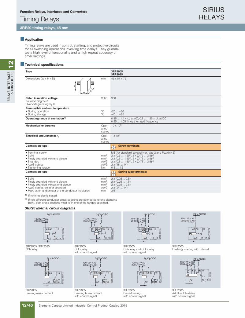
SIRIUS RELAYS
Siemens Canada Limited Industrial Control Product Catalog 201912/40
12
RELA
YS, I
NTE
RFA
CES
& C
ON
VERT
ERS
10/58 Siemens IC 10 · 2016
RelaysTiming Relays
SIRIUS 3RP20 timing relays, 45 mm
10
ApplicationTiming relays are used in control, starting, and protective circuits for all switching operations involving time delays. They guaran-tee a high level of functionality and a high repeat accuracy of timer settings.
Technical specifications
1) If nothing else is stated.2) If two different conductor cross-sections are connected to one clamping
point, both cross-sections must lie in one of the ranges specified.
3RP20 internal circuit diagrams
Type 3RP2005,3RP2025
mm)D x H x W( snoisnemiD 45 x 57 x 73
Rated insulation voltage Pollution degree 3Overvoltage category III
V AC 300
Permissible ambient temperatureC°noitarepo gniruD• -25 ... +60C°egarots gniruD• -40 ... +85
Operating range at excitation1) 0.85 ... 1.1 x Us at AC; 0.8 ... 1.25 x Us at DC; 0.95 ... 1.05 times the rated frequency
Mechanical endurance -repO ating cycles
10 x 106
Electrical endurance at Ie Oper-ating cycles
1 x 10⁵
Connection type Screw terminals
wercs lanimreT• M3 (for standard screwdriver, size 2 and Pozidriv 2)mmdiloS• 2 2 x (0.5 ... 1.5)2), 2 x (0.75 ... 2.5)2)
mm eveels dne htiw dednarts yleniF• 2 2 x (0.5 ... 1.5)2), 2 x (0.75 ... 2.5)2)
GWAdednartS• 2 x (0.5 ... 1.5)2), 2 x (0.75 ... 2.5)2)
GWAselbac GWA• 2 x (18 ... 14)mNeuqrot gninethgiT• 0.8 … 1.2
Connection type Spring-type terminals
mmdiloS• 2 2 x (0.25 ... 2.5)mmeveels dne htiw dednarts yleniF• 2 2 x (0.25 ... 1.5)mmeveels dne tuohtiw dednarts yleniF• 2 2 x (0.25 ... 2.5)
GWAdednarts ro dilos ,selbac GWA• 2 x (24 ... 14)• Max. external diameter of the conductor insulation mm 3.6
W
H
D
5002PR35002PR35002PR35202PR3 ,5002PR3 yaled-FFOyaled-NO
with control signalON-delay and OFF-delay with control signal
Flashing, starting with interval
5002PR35002PR35002PR35002PR3Passing make contact Passing break contact
with control signalPulse-forming with control signal
Additive ON-delay with control signal
A1
16 NS
B0_
0089
7a
18A2
15A3
100/127 V AC
24 V AC/DC
200/240 V AC
B3B1 A3
16 18A2
15A1
NS
B0_
0089
8a
200/240 V AC100/127 V AC
24 V AC/DC
B3B1 A3
16 18A2
15A1
NSB
0_00
899a
200/240 V AC100/127 V AC
24V AC/DC
~
A1
16 NS
B0_
0090
0a
18A2
15A3
200/240 V AC100/127 V AC
24 V AC/DC
A1
16 NS
B0_
0090
1a
18A2
15A3
200/240 V AC100/127 V AC
24 V AC/DC
16 18
15B3B1 A3
A2
A1
NSB
0_00
902a
200/240 V AC100/127 V AC
24 V AC/DC
16 18
15B3B1 A3
A2
A1
NSB
0_00
903a
200/240 V AC100/127 V AC
24 V AC/DC
B3B1 A3A1
200/240 V AC100/127 V AC
24 V AC/DC
IC01
_004
00
18A2
15
16
IC10_10_05.fm Page 58 Tuesday, June 14, 2016 12:08 PM
Function Relays, Interfaces and Converters
Timing Relays3RP20 timing relays, 45 mm
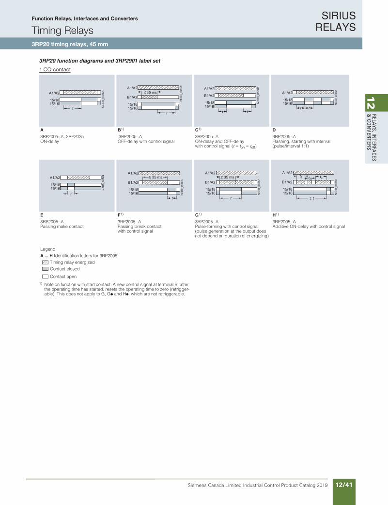
SIRIUS RELAYS
Siemens Canada Limited Industrial Control Product Catalog 2019 12/41
12
RELAYS, IN
TERFACES
& CO
NVERTERS
10/59Siemens IC 10 · 2016
RelaysTiming Relays
SIRIUS 3RP20 timing relays, 45 mm
10
3RP20 function diagrams and 3RP2901 label set
1 CO contact
1) Note on function with start contact: A new control signal at terminal B, after the operating time has started, resets the operating time to zero (retrigger-able). This does not apply to G, G! and H!, which are not retriggerable.
A B1) C1) D
3RP2005-.A, 3RP2025 3RP2005-.A 3RP2005-.A 3RP2005-.AON-delay OFF-delay with control signal ON-delay and OFF-delay
with control signal (t = ton = toff) Flashing, starting with interval (pulse/interval 1:1)
E F1) G1) H1)
3RP2005-.A 3RP2005-.A 3RP2005-.A 3RP2005-.APassing make contact Passing break contact
with control signalPulse-forming with control signal (pulse generation at the output does not depend on duration of energizing)
Additive ON-delay with control signal
Legend
A ... H Identification letters for 3RP2005
Timing relay energized
Contact closed
Contact open
15/18
A1/A2
15/16N
SB
0_00
858
t
>B1/A2
NS
B0_
0085
9
35 ms
t15/1615/18
A1/A2
B1/A2
15/18
A1/A2
15/16
NS
B0_
0086
1
t t
15/18
A1/A2
15/16tt
NSB
0_00
862
15/1615/18
A1/A2
t
NSB
0_00
864
B1/A2
15/1615/18
A1/A2> 35 ms
NS
B0_
0086
5
t
35 msB1/A2
15/1615/18
A1/A2>
NS
B0_
0086
7
t
B1/A2
15/1615/18
A1/A2t3t2t1
NS
B0_
0086
8
t
IC10_10_05.fm Page 59 Tuesday, June 14, 2016 12:08 PM
Function Relays, Interfaces and Converters
Timing Relays3RP20 timing relays, 45 mm
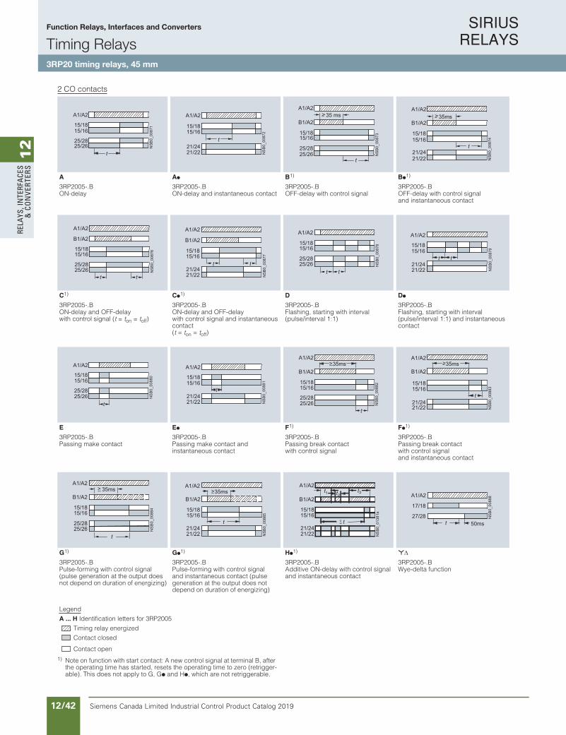
SIRIUS RELAYS
Siemens Canada Limited Industrial Control Product Catalog 201912/42
12
RELA
YS, I
NTE
RFA
CES
& C
ON
VERT
ERS
10/60 Siemens IC 10 · 2016
RelaysTiming Relays
SIRIUS 3RP20 timing relays, 45 mm
10
2 CO contacts
1) Note on function with start contact: A new control signal at terminal B, after the operating time has started, resets the operating time to zero (retrigger-able). This does not apply to G, G! and H!, which are not retriggerable.
A A! B1) B!1)
3RP2005-.B 3RP2005-.B 3RP2005-.B 3RP2005-.BON-delay ON-delay and instantaneous contact OFF-delay with control signal OFF-delay with control signal
and instantaneous contact
C1) C!1) D D!
3RP2005-.B 3RP2005-.B 3RP2005-.B 3RP2005-.BON-delay and OFF-delay with control signal (t = ton = toff)
ON-delay and OFF-delay with control signal and instantaneous contact (t = ton = toff)
Flashing, starting with interval (pulse/interval 1:1)
Flashing, starting with interval (pulse/interval 1:1) and instantaneous contact
E E! F1) F!1)
3RP2005-.B 3RP2005-.B 3RP2005-.B 3RP2005-.BPassing make contact Passing make contact and
instantaneous contactPassing break contact with control signal
Passing break contactwith control signal and instantaneous contact
G1) G!1) H!1) *3RP2005-.B 3RP2005-.B 3RP2005-.B 3RP2005-.BPulse-forming with control signal (pulse generation at the output does not depend on duration of energizing)
Pulse-forming with control signal and instantaneous contact (pulse generation at the output does not depend on duration of energizing)
Additive ON-delay with control signal and instantaneous contact
Wye-delta function
Legend
A ... H Identification letters for 3RP2005
Timing relay energized
Contact closed
Contact open
25/2625/28
15/1615/18
A1/A2
NS
B0_
0087
1t 21/22
21/24
NS
B0_
0087
2
A1/A2
t15/1615/18
35 ms
25/2625/28
B1/A2
15/1615/18
A1/A2>
NS
B0_
0087
3
t
>B1/A2
A1/A2
NS
B0_
0087
4
21/2221/24
35ms
t15/1615/18
NS
B0_
0087
6
t
B1/A2
A1/A2
25/2625/28
t
15/1615/18
NS
B0_
0087
7t
B1/A2
A1/A2
21/2221/24
t15/1615/18
NSB
0_00
878
t25/2625/28
A1/A2
t
15/1615/18
tt
A1/A2
NSB
0_00
879
21/2221/24
15/1615/18
NS
B0_
0088
0
25/2625/28
A1/A2
t
15/1615/18
t
A1/A2
NS
B0_
0088
1
21/2221/24
15/1615/18
A1/A2
B1/A2
25/26
>
NS
B0_
0088
2
35ms
25/28
t
15/1615/18
>B1/A2
A1/A2
NS
B0_
0088
3
21/2221/24
35ms
t15/1615/18
>
NS
B0_
0088
4
35msB1/A2
A1/A2
25/2625/28
t
15/1615/18
>35ms
NS
B0_
0088
5
t
B1/A2
A1/A2
21/2221/24
15/1615/18
t
2ttt1 3
B1/A2
A1/A2
21/2221/24
15/1615/18
NS
B0_
0138
1a
NS
B0_
0088
8
27/28
17/18
50ms
A1/A2
t
IC10_10_05.fm Page 60 Tuesday, June 14, 2016 12:08 PM
Function Relays, Interfaces and Converters
Timing Relays3RP20 timing relays, 45 mm

SIRIUS RELAYS
Siemens Canada Limited Industrial Control Product Catalog 2019 12/43
12
RELAYS, IN
TERFACES
& CO
NVERTERS
10/61Siemens IC 10 · 2016* You can order this quantity or a multiple thereof.Illustrations are approximate
RelaysTiming Relays
SIRIUS 3RP20 timing relays, 45 mm
10
Selection and ordering data
PU (UNIT, SET, M) = 1PS* = 1 unitPG = 41H
For accessories, see page 10/62.1) Units with protective separation.2) With switch position no timing. For test purposes (ON/OFF function) on
site. Relay is constantly on when activated, or relay remains constantly off when activated. Depending on which function is set.
3) Operating range 0.8 to 1.1 x Us.4) Operating range 0.7 to 1.1 x Us.
Version Time setting range t
Rated control supply voltage Us DT Screw terminals DT Spring-typeterminals
50/60 Hz AC DC
Article No. Priceper PU
Article No. Priceper PUV V
3RP2005 timing relays, multifunction, 15 time setting rangesThe functions can be adjusted by means of rotary switches. Insert labels can be used to adjust different functions of the 3RP2505 timing relay clearly and unmis-takably. The corresponding labels can be ordered as an accessory. The same potential must be applied to terminals A. and B. For functions, see 3RP2901 label set, page 10/62.
With LED and1 CO contact1), 8 functions
0.05 ... 1 s0.15 ... 3 s0.5 ... 10 s1.5 ... 30 s0.05 ... 1 min5 ... 100 s0.15 ... 3 min0.5 ... 10 min1.5 ... 30 min0.05 ... 1 h5 ... 100 min0.15 ... 3 h0.5 ... 10 h1.5 ... 30 h5 ... 100 h2)
24/100 ... 127 24 3RP2005-1AQ30 A 3RP2005-2AQ3024/200 ... 240 24 3RP2005-1AP30 3RP2005-2AP30
With LED and 2 CO contacts, 16 functions
24 ... 2403) 24 ... 2404) 3RP2005-1BW30 A 3RP2005-2BW30
3RP2025. timing relays, ON-delay, 15 time setting rangesWith LED and 1 CO contact1)
0.05 ... 1 s0.15 ... 3 s0.5 ... 10 s1.5 ... 30 s0.05 ... 1 min5 ... 100 s0.15 ... 3 min0.5 ... 10 min1.5 ... 30 min0.05 ... 1 h5 ... 100 min0.15 ... 3 h0.5 ... 10 h1.5 ... 30 h5 ... 100 h2)
24/100 ... 127 24 3RP2025-1AQ30 3RP2025-2AQ3024/200 ... 240 24 3RP2025-1AP30 3RP2025-2AP30
3RP2025-2BW303RP2005-1AP30 3RP2005-1BW30 3RP2005-2AP30
IC10_10_05.fm Page 61 Tuesday, June 14, 2016 12:08 PM
For functions, see 3RP2901 label set, page 12/44.
For accessories, see page 12/44.
Function Relays, Interfaces and Converters
Timing Relays3RP20 timing relays, 45 mm

SIRIUS RELAYS
Siemens Canada Limited Industrial Control Product Catalog 201912/44
12
RELA
YS, I
NTE
RFA
CES
& C
ON
VERT
ERS
10/62 Siemens IC 10 · 2016* You can order this quantity or a multiple thereof.
Illustrations are approximate
RelaysTiming Relays
SIRIUS 3RP20 timing relays, 45 mm
10
Accessories
1) PC labeling system for individual inscription of unit labeling plates available from:murrplastik Systemtechnik GmbH
Version Function Identifi-cation letter
Use DT Article No. Priceper PU
PU(UNIT,
SET, M)
PS* PG
Label sets for 3RP20 Accessories for 3RP20 (not included in the scope of supply).
The label set offers the possibility of labeling timing relays with the set function in English and German.
3RP2901-0A
1 label set (1 unit) with 8 functions
Ayaled-NO
For devices with 1 CO
C 3RP2901-0A 1 5 units 41H
OFF-delay with control signal B
ON-delay and OFF-delay with control signal
C
Flashing, starting with interval D
Passing make contact E
Passing break contact with control signal
F
Pulse-forming with control signal G
Additive ON-delay with control signal
H
3RP2901-0B
1 label set (1 unit) with 16 functions
Ayaled-NO
For devices with 2 CO contacts
C 3RP2901-0B 1 5 units 41H
OFF-delay with control signal B
ON-delay and OFF-delay with control signal
C
Flashing, starting with interval D
Passing make contact E
Passing break contact with control signal
F
Pulse-forming with control signal G
ON-delay and instantaneous con-tact
A•
OFF-delay with control signal and instantaneous contact
B•
ON-delay and OFF-delay with control signal and instantaneous contact
C•
Flashing, starting with interval, and instantaneous contact
D•
Passing make contact and instan-taneous contact
E•
Passing break contact with control signal and instantaneous contact
F•
Pulse-forming with control signal and instantaneous contact
G•
Additive ON-delay with control signal and instantaneous contact
H•
Wye-delta function *∆Blank inscription labels for 3RP20
Blank labels, 20 mm x 7 mm, pastel turquoise1)
For 3RP20 D 3RT1900-1SB20 100 340 units 41B
IC10_10_05.fm Page 62 Tuesday, June 14, 2016 12:08 PM
Function Relays, Interfaces and Converters
Timing Relays3RP20 timing relays, 45 mm

SIRIUS RELAYS
Siemens Canada Limited Industrial Control Product Catalog 2019 12/45
12
RELAYS, IN
TERFACES
& CO
NVERTERS
10/63Siemens IC 10 · 2016
RelaysTiming Relays
7PV15 timing relays in enclosure, 17.5 mm
10
Overview
7PV15 timing relay
Electronic timing relays for general use and in control systems, mechanical engineering and infrastructure with:• 1 or 2 CO contacts• Multifunction or monofunction• Wide voltage range or combination voltage• Single or selectable time setting ranges• Switch position indication and voltage indication by LED
Standards
The timing relays comply with: • IEC 60721-3-3 "Classification of environmental conditions"• IEC 61812-1 "Time relays for industrial and residential use"• IEC 61000-6-2 and EN 61000-6-4
"Electromagnetic compatibility"• IEC 60947-5-1 "Low-voltage switchgear and controlgear –
Electromechanical control circuit devices"• DIN 43880 "Built-in equipment for electrical installations;
overall dimensions and related mounting dimensions"
Multifunction
The functions of the 7PV1508-1A multifunctional timing relays can be set by means of rotary switches. The identification letters A to G are printed on the front alongside the rotary selector switch of the unit. The related function can be found in the form of a bar graph on the side of the device.
Enclosure version
All timing relays are suitable for snap-on mounting onto TH 35 standard mounting rails according to IEC 60715. The enclosure complies with DIN 43880, 1 MW.
Dimensions
Note:
The activation of loads parallel to the start input is not permissi-ble when using AC control voltage (see diagrams).
Diagrams
Article No. scheme
Note:
The Article No. scheme is presented here merely for information purposes and for better understanding of the logic behind the article numbers.
For your orders, please use the article numbers quoted in the catalog in the Selection and ordering data.
67
43255
4590,5
NSB0_02042a
67,5
17,5
NSB0_00895a
K2A1
A2N
L1
S1
K1B1
NSB0_02045
K2A1
A2N
L1
K1 S1
K1B1
Digit of the Article No. 1st - 5th 6th 7th 8th 9th 10th 11th 12th
@@@@@ @ @ – @ @ @ @ 0
Timing relays in industrial enclosure, 17.5 mm 7 P V 1 5
Functions/time setting ranges @ @Connection type @Contacts @Rated control supply voltage @ @Example 7 P V 1 5 0 8 – 1 A W 3 0
IC10_10_05.fm Page 63 Tuesday, June 14, 2016 12:08 PM
Function Relays, Interfaces and Converters
Timing Relays7PV15 timing relays in enclosure, 17.5 mm
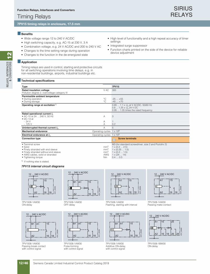
SIRIUS RELAYS
Siemens Canada Limited Industrial Control Product Catalog 201912/46
12
RELA
YS, I
NTE
RFA
CES
& C
ON
VERT
ERS
10/64 Siemens IC 10 · 2016
RelaysTiming Relays
7PV15 timing relays in enclosure, 17.5 mm
10
Benefits
• Wide voltage range 12 to 240 V AC/DC• High switching capacity, e.g. AC-15 at 230 V, 3 A• Combination voltage, e.g. 24 V AC/DC and 200 to 240 V AC• Changes to the time setting range during operation• Changes to the function in the de-energized state
• High level of functionality and a high repeat accuracy of timer settings
• Integrated surge suppressor• Function charts printed on the side of the device for reliable
device adjustment
Application
Timing relays are used in control, starting and protective circuits for all switching operations involving time delays, e.g. in non-residential buildings, airports, industrial buildings etc.
Technical specifications
1) If nothing else is stated.
7PV15 internal circuit diagrams
Type 7PV15
Rated insulation voltage Pollution degree 2, overvoltage category III
V AC 300
Permissible ambient temperature• During operation °C -25 ... +55 • During storage °C -40 ... +70
Operating range at excitation1) 0.85 ... 1.1 x Us at V AC/DC, 50/60 Hz0.8 ... 1.25 x Us 24 V DC0.95 ... 1.05 times the rated frequency
Rated operational current Ie
• AC-15 at 24 ... 240 V, 50 Hz A 3• DC-13 at
- 24 V A 1- 125 V A 0.2
Uninterrupted thermal current Ith A 5
Mechanical endurance Operating cycles 1 x 10⁶
Electrical endurance at Ie Operating cycles 1 x 10⁵
Connection type Screw terminals
• Terminal screw M3 (for standard screwdriver, size 2 and Pozidriv 2)• Solid mm2 1 x (0.2 ... 2.5)• Finely stranded with end sleeve mm2 1 x (0.25 ... 1.5)• Finely stranded without end sleeve mm2 1 x (0.2 ... 1.5)• AWG cables, solid or stranded AWG 1 x (24 ... 14)• Tightening torque Nm 0.4 … 0.5
7PV1508-1AW30 7PV1508-1AW30 7PV1508-1AW30 7PV1508-1AW30ON-delay OFF-delay Flashing, starting with interval Passing make contact
7PV1508-1AW30 7PV1508-1AW30 7PV1508-1AW30 7PV1508-1BW30Passing break contact with control signal
Pulse-forming with control signal
Additive ON-delay,with control signal
ON-delay
12 ... 240 V AC/DC
18A2
15
16
A1
IC01
_000
53
12 ... 240 V AC/DC
IC01
_000
57
18A2
15A1
16
B1
12 ... 240 V AC/DC
IC01
_000
54
18A2
15
16
A1
12 ... 240 V AC/DC
IC01
_000
58
18A2
15
16
A1
12 ... 240 V AC/DC
IC01
_000
55
18A2
15A1
16
B1
12 ... 240 V AC/DC
IC01
_000
59
18A2
15A1
16
B1
12 ... 240 V AC/DC
IC01
_000
56
B1
18A2
15A1
16
12 ... 240 V AC/DC
IC01
_000
60
28
25
2618A2
15
16
A1
IC10_10_05.fm Page 64 Tuesday, June 14, 2016 12:08 PM
Function Relays, Interfaces and Converters
Timing Relays7PV15 timing relays in enclosure, 17.5 mm

SIRIUS RELAYS
Siemens Canada Limited Industrial Control Product Catalog 2019 12/47
12
RELAYS, IN
TERFACES
& CO
NVERTERS
10/65Siemens IC 10 · 2016
RelaysTiming Relays
7PV15 timing relays in enclosure, 17.5 mm
10
7PV15 internal circuit diagrams (continued)
7PV1508-1BW30 7PV1508-1BW30 7PV1508-1BW30 7PV1508-1BW30OFF-delay with control signal
Flashing, starting with interval
Passing make contact Pulse-forming with control signal
7PV1508-1BW30 7PV1508-1BW30 7PV151.-1AQ30, 7PV151.-1AP30 7PV1518-1AJ30, 7PV1518-1AN30ON and OFF-delay Fixed pulse after ON-delay ON-delay ON-delay
7PV1518-1AW30 7PV1538-1AW30 7PV1540-1AW30 7PV1558-1AW30ON-delay OFF-delay
with control signal OFF-delaywithout control signal
Clock-pulse relay
7PV1578-1BW30Wye-delta
12 ... 240 V AC/DC
IC01
_000
63
25
282618A2
15A1
16
B1
12 ... 240 V AC/DC
IC01
_000
61
25
282618A2
15
16
A1
12 ... 240 V AC/DC
IC01
_000
64
25
282618A2
15
16
A1
12 ... 240 V AC/DC
IC01
_000
62
25
282618A3
15A1
16
B1
12 ... 240 V AC/DC
IC01
_000
65
28
25
2618A2
15A1
16
B1
12 ... 240 V AC/DC
IC01
_000
66
25
282618A2
15
16
A1
24 V AC/DC
200 ... 240 V AC100 ... 127 V AC
IC01
_000
67
18A2
15
16
A1 A3
90 ... 240 V AC/DC180 ... 240 V AC/DC
IC01
_000
68
18A2
15
16
A1B1
12 ... 240 V AC/DC
IC01
_000
69
18A2
15
16
A1
12 ... 240 V AC/DC
IC01
_000
70
18A2
15
16
A1B1
12 ... 240 V AC/DC
IC01
_000
71
18A2
15
16
A1
12 ... 240 V AC/DC
IC01
_000
72
18A2
15
16
A1
12 ... 240 V AC/DC
IC01
_000
73
25
28A2
15
18
A1
IC10_10_05.fm Page 65 Tuesday, June 14, 2016 12:08 PM
Function Relays, Interfaces and Converters
Timing Relays7PV15 timing relays in enclosure, 17.5 mm
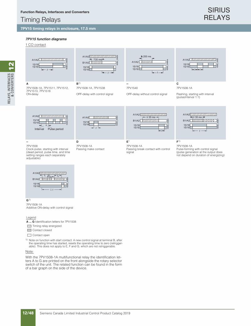
SIRIUS RELAYS
Siemens Canada Limited Industrial Control Product Catalog 201912/48
12
RELA
YS, I
NTE
RFA
CES
& C
ON
VERT
ERS
10/66 Siemens IC 10 · 2016
RelaysTiming Relays
7PV15 timing relays in enclosure, 17.5 mm
10
7PV15 function diagrams
1 CO contact
1) Note on function with start contact: A new control signal at terminal B, after the operating time has started, resets the operating time to zero (retrigger-able). This does not apply to E, F and G, which are not retriggerable.
Note:
With the 7PV1508-1A multifunctional relay the identification let-ters A to G are printed on the front alongside the rotary selector switch of the unit. The related function can be found in the form of a bar graph on the side of the device.
A B1) -- C
7PV1508-1A, 7PV1511, 7PV1512, 7PV1513, 7PV1518
7PV1508-1A, 7PV1538 7PV1540 7PV1508-1A
ON-delay OFF-delay with control signal OFF-delay without control signal Flashing, starting with interval (pulse/interval 1:1)
-- D E1 F1)
7PV1558 7PV1508-1A 7PV1508-1A 7PV1508-1AClock-pulse, starting with interval (dead period, pulse time, and time setting ranges each separately adjustable)
Passing make contact Passing break contact with control signal
Pulse-forming with control signal (pulse generation at the output does not depend on duration of energizing)
G1)
7PV1508-1AAdditive ON-delay with control signal
Legend
A ... G Identification letters for 7PV1508
Timing relay energized
Contact closed
Contact open
15/18
A1/A2
15/16N
SB
0_00
858
t
>B1/A2
NS
B0_
0085
9
35 ms
t15/1615/18
A1/A2
NS
B0_
0086
0a
15/18
t
200 ms
A1/A2
15/16
15/18
A1/A2
15/16tt
NSB
0_00
862
NSB
0_00
863
15/16
A1/A2
15/18
Interval Pulse period15/1615/18
A1/A2
t
NSB
0_00
864
B1/A2
15/1615/18
A1/A2> 35 ms
NS
B0_
0086
5
t
35 msB1/A2
15/1615/18
A1/A2>
NS
B0_
0086
7
t
B1/A2
15/1615/18
A1/A2t3t2t1
NS
B0_
0086
8
t
IC10_10_05.fm Page 66 Tuesday, June 14, 2016 12:08 PM
Function Relays, Interfaces and Converters
Timing Relays7PV15 timing relays in enclosure, 17.5 mm
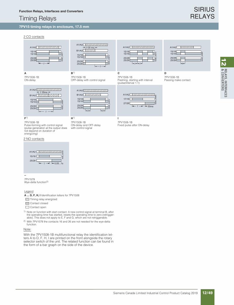
SIRIUS RELAYS
Siemens Canada Limited Industrial Control Product Catalog 2019 12/49
12
RELAYS, IN
TERFACES
& CO
NVERTERS
10/67Siemens IC 10 · 2016
RelaysTiming Relays
7PV15 timing relays in enclosure, 17.5 mm
10
2 CO contacts
2 NO contacts
1) Note on function with start contact: A new control signal at terminal B, after the operating time has started, resets the operating time to zero (retrigger-able). This does not apply to E, F and G, which are not retriggerable.
2) With 7PV1578 the contacts 16 and 26 are not needed for the wye-delta function.
Note:
With the 7PV1508-1B multifunctional relay the identification let-ters A to D, F, H, I are printed on the front alongside the rotary selector switch of the unit. The related function can be found in the form of a bar graph on the side of the device.
A B1) C D
7PV1508-1B 7PV1508-1B 7PV1508-1B 7PV1508-1BON-delay OFF-delay with control signal Flashing, starting with interval
(pulse/interval 1:1)Passing make contact
F1) H1) I
7PV1508-1B 7PV1508-1B 7PV1508-1BPulse-forming with control signal (pulse generation at the output does not depend on duration of energizing)
ON-delay and OFF-delaywith control signal
Fixed pulse after ON-delay
25/2625/28
15/1615/18
A1/A2
NS
B0_
0087
1t
35 ms
25/2625/28
B1/A2
15/1615/18
A1/A2>
NS
B0_
0087
3
t
NSB
0_00
878
t25/2625/28
A1/A2
t
15/1615/18
NS
B0_
0088
0
25/2625/28
A1/A2
t
15/1615/18
>
NS
B0_
0088
4
35msB1/A2
A1/A2
25/2625/28
t
15/1615/18
NS
B0_
0087
6t
B1/A2
A1/A2
25/2625/28
t
15/1615/18
NS
B0_
0088
8
27/28
17/18
50ms
A1/A2
t
--
7PV1578Wye-delta function2)
Legend
A ... D, F, H, I Identification letters for 7PV1508
Timing relay energized
Contact closed
Contact open
NSB
_020
44
25/28
15/18
0,05...1s
A1/A2
t
IC10_10_05.fm Page 67 Tuesday, June 14, 2016 12:08 PM
Function Relays, Interfaces and Converters
Timing Relays7PV15 timing relays in enclosure, 17.5 mm

SIRIUS RELAYS
Siemens Canada Limited Industrial Control Product Catalog 201912/50
12
RELA
YS, I
NTE
RFA
CES
& C
ON
VERT
ERS
10/68 Siemens IC 10 · 2016* You can order this quantity or a multiple thereof.
Illustrations are approximate
RelaysTiming Relays
7PV15 timing relays in enclosure, 17.5 mm
10
Selection and ordering data
Version Time setting range tadjustable by rotary switch to
Rated control supply voltage Us
DT Screw terminals PU(UNIT,
SET, M)
PS* PG
50/60 Hz AC DC Article No. Priceper PUV V
7PV1508 timing relays, multifunction, 7 time setting ranges
The functions can be adjusted by means of rotary switches. The same potential must be applied to terminals A. and B.
With LED and 1 CO contact, 7 functions
0.05 ... 1 s 0.5 ... 10 s 5 ... 100 s30 s ... 10 min 3 min ... 1 h 30 min ... 10 h5 ... 100 h
12 ... 240 12 ... 240 7PV1508-1AW30 1 1 unit 41H
With LED and 2 CO contacts, 7 functions
12 ... 240 12 ... 240 7PV1508-1BW30 1 1 unit 41H
7PV151. timing relays, ON-delay, 1 time setting range
With LED and1 CO contact
0.05 ... 1 s 24/200 ... 240 24 7PV1511-1AP30 1 1 unit 41H
0.5 ... 10 s 24/100 ... 127 24 7PV1512-1AQ30 1 1 unit 41H24/200 ... 240 24 7PV1512-1AP30 1 1 unit 41H
5 ... 100 s 24/100 ... 127 24 7PV1513-1AQ30 1 1 unit 41H24/200 ... 240 24 7PV1513-1AP30 1 1 unit 41H
7PV1518 timing relays, ON-delay, 7 time setting ranges
With LED and1 CO contact
0.05 ... 1 s 0.5 ... 10 s 5 ... 100 s30 s ... 10 min 3 min ... 1 h 30 min ... 10 h5 ... 100 h
12 ... 240 12 ... 240 7PV1518-1AW30 1 1 unit 41H
90 ... 127 90 ... 127 7PV1518-1AJ30 1 1 unit 41H
180 ... 240 180 ... 240 7PV1518-1AN30 1 1 unit 41H
7PV1538 timing relays, OFF-delay, with control signal, 7 time setting range
With LED and1 CO contact
0.05 ... 1 s 0.5 ... 10 s 5 ... 100 s30 s ... 10 min 3 min ... 1 h 30 min ... 10 h5 ... 100 h
12 ... 240 12 ... 240 7PV1538-1AW30 1 1 unit 41H
7PV1540 timing relays, OFF-delay, without control signal, 7 time setting ranges
With LED and1 CO contact
0.05 ... 1 s 0.15 ... 3s 0.3 ... 6 s0.5 ... 10 s 1.5 ... 30 s3 ... 60 s5 ... 100 s
12 ... 240 12 ... 240 7PV1540-1AW30 1 1 unit 41H
7PV1558 timing relays, clock-pulse relay, 7 time setting ranges
With LED and1 CO contact
0.05 ... 1 s 0.5 ... 10 s 5 ... 100 s30 s ... 10 min 3 min ... 1 h 30 min ... 10 h5 ... 100 h
12 ... 240 12 ... 240 7PV1558-1AW30 1 1 unit 41H
7PV1578 timing relays, wye-delta function, 7 time setting ranges
With LED and 2 NO contacts, dead interval 0.05 ... 1 s adjustable
0.05 ... 1 s 0.5 ... 10 s 5 ... 100 s30 s ... 10 min 3 min ... 1 h 30 min ... 10 h5 ... 100 h
12 ... 240 12 ... 240 7PV1578-1BW30 1 1 unit 41H
7PV1538-1AW307PV1508-1AW30 7PV1512-1AP30 7PV1518-1AW30 7PV1558-1AW30 7PV1578-1BW307PV1540-1AW30
IC10_10_05.fm Page 68 Tuesday, June 14, 2016 12:08 PM
Function Relays, Interfaces and Converters
Timing Relays7PV15 timing relays in enclosure, 17.5 mm
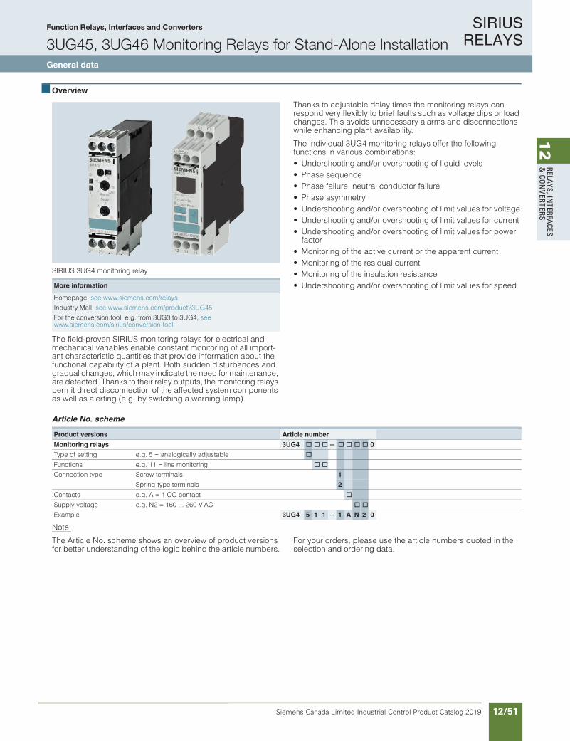
SIRIUS RELAYS
Siemens Canada Limited Industrial Control Product Catalog 2019 12/51
12
RELAYS, IN
TERFACES
& CO
NVERTERS
Siemens / Industrial Controls Previous folio: IC10 11/30
Function Relays, Interfaces and Converters
3UG45, 3UG46 Monitoring Relays for Stand-Alone InstallationGeneral data
10/79Siemens IC 10 · 2018
RelaysSIRIUS 3UG45, 3UG46 Monitoring Relays for Stand-Alone Installation
General data
10
Overview
SIRIUS 3UG4 monitoring relay
The field-proven SIRIUS monitoring relays for electrical and mechanical variables enable constant monitoring of all import-ant characteristic quantities that provide information about the functional capability of a plant. Both sudden disturbances and gradual changes, which may indicate the need for maintenance, are detected. Thanks to their relay outputs, the monitoring relays permit direct disconnection of the affected system components as well as alerting (e.g. by switching a warning lamp).
Thanks to adjustable delay times the monitoring relays can respond very flexibly to brief faults such as voltage dips or load changes. This avoids unnecessary alarms and disconnections while enhancing plant availability.
The individual 3UG4 monitoring relays offer the following functions in various combinations:• Undershooting and/or overshooting of liquid levels• Phase sequence• Phase failure, neutral conductor failure• Phase asymmetry• Undershooting and/or overshooting of limit values for voltage• Undershooting and/or overshooting of limit values for current• Undershooting and/or overshooting of limit values for power
factor• Monitoring of the active current or the apparent current• Monitoring of the residual current• Monitoring of the insulation resistance• Undershooting and/or overshooting of limit values for speed
Article No. scheme
Note:
The Article No. scheme shows an overview of product versions for better understanding of the logic behind the article numbers.
For your orders, please use the article numbers quoted in the selection and ordering data.
More information
Homepage, see www.siemens.com/relays
Industry Mall, see www.siemens.com/product?3UG45
For the conversion tool, e.g. from 3UG3 to 3UG4, see www.siemens.com/sirius/conversion-tool
Product versions Article number
Monitoring relays 3UG4 @ @ @ – @ @ @ @ 0
Type of setting e.g. 5 = analogically adjustable @
Functions e.g. 11 = line monitoring @ @
Connection type Screw terminals 1
Spring-type terminals 2
Contacts e.g. A = 1 CO contact @
Supply voltage e.g. N2 = 160 ... 260 V AC @ @
Example 3UG4 5 1 1 – 1 A N 2 0
IC10_10_08.fm Page 79 Thursday, February 22, 2018 9:50 PM

SIRIUS RELAYS
Siemens Canada Limited Industrial Control Product Catalog 201912/52
12
RELA
YS, I
NTE
RFA
CES
& C
ON
VERT
ERS
Siemens / Industrial Controls Previous folio: IC10 11/31
Function Relays, Interfaces and Converters
3UG45, 3UG46 Monitoring Relays for Stand-Alone InstallationGeneral data
Product Category: SMRL
10/80 Siemens IC 10 · 2018
RelaysSIRIUS 3UG45, 3UG46 Monitoring Relays for Stand-Alone Installation
General data
10
Benefits
• Customary screw and spring-type terminals for quick and reliable wiring
• Fast commissioning thanks to menu-guided parameterization and actual value display for limit value determination
• Reduced space requirement in the control cabinet thanks toa consistent width of 22.5 mm
• Parameterizable monitoring functions, delay times, RESET response, etc.
• Reduced stockkeeping thanks to minimized variance and large measuring ranges
• Wide-voltage power supply units for global applicability• Device replacement without renewed wiring thanks to
removable terminals• Reliable system diagnostics thanks to actual value display
and connectable fault memory• Rapid diagnostics thanks to unambiguous error messages on
the display
Application
The SIRIUS 3UG4 monitoring relays monitor the most diverse electrical and mechanical quantities in the feeder, and provide reliable protection against damage in the plant. For this purpose, they offer freely parameterizable limit values and diverse options for adapting to the respective task, and in the event of a fault, they provide clear diagnostics information.
The digitally adjustable products also display the current mea-sured values direct on the device. This not only facilitates the display of valuable plant status information during operation, it also enables adjustment of the monitored limit values in accor-dance with the actual conditions.
The positive result: More selective avoidance of production faults – sustained increases in availability and productivity.
The 3UG4 monitoring relays are available for the following applications:• Line and single-phase voltage monitoring• Single-phase current monitoring or power factor and active
current monitoring• Residual current monitoring• Insulation monitoring• Level monitoring• Speed monitoring
Technical specifications
More information
Technical specifications, see https://support.industry.siemens.com/cs/ww/en/ps/16367/td
Manual and internal circuit diagrams, seehttps://support.industry.siemens.com/cs/ww/en/view/54397927
FAQs, see https://support.industry.siemens.com/cs/ww/en/ps/16367/faq
Type 3UGGeneral dataDimensions (W x H x D)
• For 2 terminal blocks- Screw terminals mm 22.5 x 83 x 91- Spring-type terminals mm 22.5 x 84 x 91
• For 3 terminal blocks- Screw terminals mm 22.5 x 92 x 91- Spring-type terminals mm 22.5 x 94 x 91
• For 4 terminal blocks- Screw terminals mm 22.5 x 103 x 91- Spring-type terminals mm 22.5 x 103 x 91
Permissible ambient temperature• During operation °C -25 ... +60
Connection type Screw terminals
• Terminal screw M3 (for standard screwdriver, size 2 and Pozidriv 2)• Solid mm2 1 x (0.5 ... 4)/2 x (0.5 ... 2.5)• Finely stranded with end sleeve mm2 1 x (0.5 ... 2.5)/2 x (0.5 ... 1.5)• AWG cables, solid or stranded AWG 2 x (20 ... 14)
Connection type Spring-type terminals
• Solid mm2 2 x (0.25 ... 1.5)• Finely stranded, with end sleeve acc. to DIN 46228 mm2 2 x (0.25 ... 1.5)• Finely stranded mm2 2 x (0.25 ... 1.5)• AWG cables, solid or stranded AWG 2 x (24 ... 16)
W
H
D
IC10_10_08.fm Page 80 Thursday, February 22, 2018 9:50 PM

SIRIUS RELAYS
Siemens Canada Limited Industrial Control Product Catalog 2019 12/53
12
RELAYS, IN
TERFACES
& CO
NVERTERS
Siemens / Industrial Controls Previous folio: IC10 11/32
Function Relays, Interfaces and Converters
3UG45, 3UG46 Monitoring Relays for Stand-Alone InstallationLine monitoring
10/81Siemens IC 10 · 2018
RelaysSIRIUS 3UG45, 3UG46 Monitoring Relays for Stand-Alone Installation
Line monitoring
10
Overview
SIRIUS 3UG4615 monitoring relay
Electronic line monitoring relays provide maximum protection for mobile machines and plants or for unstable networks. Network and voltage faults can thus be detected early and rectified before far greater damage ensues.
Depending on the version, the relays monitor phase sequence, phase failure with and without N conductor monitoring, phase asymmetry, undervoltage or overvoltage.
Phase asymmetry is evaluated as the difference between the greatest and the smallest phase voltage relative to the greatest phase voltage. Undervoltage or overvoltage exists when at least one phase voltage deviates by 20% from the set rated system voltage or the directly set limit values are overshot or undershot. The rms value of the voltage is measured.
With the 3UG4617 or 3UG4618 relay, a wrong direction of rotation can also be corrected automatically.
Benefits
• Can be used without auxiliary voltage in any network from 160 to 630 V AC worldwide thanks to wide voltage range
• Variably adjustable to overshoot, undershoot or range monitoring
• Freely configurable delay times and RESET response• Width 22.5 mm• Permanent display of actual value and line fault type on the
digital versions• Automatic correction of the direction of rotation by distinguish-
ing between power system faults and wrong phase sequence• All versions with removable terminals• All versions with screw or spring-type terminals
Application
The relays are used above all for mobile equipment, e.g. air conditioning compressors, refrigerating containers, building site compressors and cranes.
Technical specifications
3UG4511 monitoring relays
The 3UG4511 phase sequenced relay monitors the phase se-quence in a three-phase network. No adjustments are required for operation. The device has an internal power supply and works using the closed-circuit principle. If the phase sequence at the terminals L1-L2-L3 is correct, the output relay picks up after the delay time has elapsed and the LED is lit. If the phase sequence is wrong, the output relay remains in its rest position.
Note:
When one phase fails, connected loads (motor windings, lamps, transformers, coils, etc.) create a feedback voltage at the termi-nal of the failed phase due to the network coupling. Because the 3UG4511 relays are not resistant to voltage feedback, such a phase failure is not detected. Should this be required, then the 3UG4512 monitoring relay must be used.
Correct phase sequence
Wrong phase sequence
Function Application
Phase sequence • Direction of rotation of the drive
Phase failure • A fuse has tripped
• Failure of the control supply voltage
• Broken cable
Phase asymmetry • Overheating of the motor due to asymmetrical voltage
• Detection of asymmetrically loaded networks
Undervoltage • Increased current on a motor with corresponding overheating
• Unintentional resetting of a device
• Network collapse, particularly with battery power
Overvoltage • Protection of a plant against destruction due to overvoltage
NS
B0_
0156
5a
11/14
L1-L2-L3
11/12
21/2421/22
ON
NS
B0_
0156
6a
11/14
L3-L2-L1
11/12
21/2421/22
OFF
IC10_10_08.fm Page 81 Thursday, February 22, 2018 9:50 PM

SIRIUS RELAYS
Siemens Canada Limited Industrial Control Product Catalog 201912/54
12
RELA
YS, I
NTE
RFA
CES
& C
ON
VERT
ERS
Siemens / Industrial Controls Previous folio: IC10 11/33
Function Relays, Interfaces and Converters
3UG45, 3UG46 Monitoring Relays for Stand-Alone InstallationLine monitoring
10/82 Siemens IC 10 · 2018
RelaysSIRIUS 3UG45, 3UG46 Monitoring Relays for Stand-Alone Installation
Line monitoring
10
3UG4512 monitoring relays
The 3UG4512 line monitoring relay monitors three-phase net-works with regard to phase sequence, phase failure and phase unbalance of 10%. Thanks to a special measuring method, a phase failure is reliably detected in spite of the wide voltage range from 160 to 690 V AC and feedback through the load of up to 90%. The device has an internal power supply and works using the closed-circuit principle. No adjustments are required. If the line voltage is switched on, the green LED will light up.If the phase sequence at the terminals L1-L2-L3 is correct, the output relay picks up. If the phase sequence is wrong, the red LED flashes and the output relay remains in its rest position. If a phase fails, the red LED is permanently lit and the output relay drops.
Note:
The red LED is a fault diagnostic indicator and does not show the current relay status. The 3UG4512 monitoring relay is suitable for line frequencies of 50/60 Hz.
Phase failure
Wrong phase sequence
3UG4513 monitoring relays
The 3UG4513 line monitoring relay monitors three-phase net-works with regard to phase sequence, phase failure, phase asymmetry and undervoltage of 20%. The device has an internal power supply and works using the closed-circuit principle. The hysteresis is 5%. The integrated response delay time T is adjust-able from 0 to 20 s and responds to undervoltage. If the direc-tion is incorrect, the device switches off immediately. Thanks to a special measuring method, a phase failure is reliably detected in spite of the wide voltage range from 160 to 690 V and feed-back through the load of up to 80%. If the line voltage is switched on, the green LED will light up. If the phase sequence at the ter-minals L1-L2-L3 is correct, the output relay picks up. If the phase sequence is wrong, the red LED flashes and the output relay re-mains in its rest position. If a phase fails, the red LED is perma-nently lit and the output relay drops.
Note:
The red LED is a fault diagnostic indicator and does not show the current relay status. The 3UG4513 monitoring relay is suitable for line frequencies of 50/60 Hz.
Phase failure and undervoltage
Wrong phase sequence
NS
B0_
0156
7a
11/14
L1-L2-L3L2-L3L1-L2-L3
11/12
21/2421/22
OFF OFFONPhase failure
LED rd
NS
B0_
0156
8a
11/1411/12
21/2421/22
L3-L2-L1
FLASHPhase sequence
OFFOFF
LED rd
11/14
-20 %L1-L2-L3L2-L3L1-L2-L3
n3~5 %
11/12
21/2421/22
DelayOFFOFF OFFON
Phase failureON
LED rd
Hysteresis
NSB0_01569b
NS
B0_
0157
0a
11/1411/12
21/2421/22
L3-L2-L1
FLASHPhase sequence
OFFOFF
LED rd
IC10_10_08.fm Page 82 Thursday, February 22, 2018 9:50 PM

SIRIUS RELAYS
Siemens Canada Limited Industrial Control Product Catalog 2019 12/55
12
RELAYS, IN
TERFACES
& CO
NVERTERS
Siemens / Industrial Controls Previous folio: IC10 11/34
Function Relays, Interfaces and Converters
3UG45, 3UG46 Monitoring Relays for Stand-Alone InstallationVoltage monitoring
10/83Siemens IC 10 · 2018
RelaysSIRIUS 3UG45, 3UG46 Monitoring Relays for Stand-Alone Installation
Line monitoring
10
3UG4614 monitoring relaysThe 3UG4614 line monitoring relay has a wide voltage range in-put and an internal power supply. The device is equipped with a display and is parameterized using three buttons. The unit mon-itors three-phase networks with regard to phase asymmetry from 5 to 20%, phase failure, undervoltage and phase sequence. The hysteresis is adjustable from 1 to 20 V. In addition the device has a response delay and ON-delay from 0 to 20 s in each case. The integrated response delay time responds to phase asymmetry and undervoltage. If the direction is incorrect, the device switches off immediately. Thanks to a special measuring method, a phase failure is reliably detected in spite of the wide voltage range from 160 to 690 V and feedback through the load of up to 80%.
The 3UG4614 monitoring relay can be operated on the basis of either the open-circuit or closed-circuit principle and with Manual or Auto RESET.
With the closed-circuit principle selected
Wrong phase sequence
Phase failure
Undervoltage
Unbalance
3UG4615/3UG4616 monitoring relays The 3UG4615/3UG4616 line monitoring relay has a wide voltage range input and an internal power supply. The device is equipped with a display and is parameterized using three but-tons. The 3UG4615 device monitors three-phase networks with regard to phase failure, undervoltage, overvoltage and phase sequence. The 3UG4616 monitoring relay monitors the neutral conductor as well. The hysteresis is adjustable from 1 to 20 V. In addition the device has two separately adjustable delay times for overvoltage and undervoltage from 0 to 20 s in each case. If the direction of rotation is incorrect, the device switches off im-mediately. Thanks to a special measuring method, a phase fail-ure is reliably detected in spite of the wide voltage range from 160 to 690 V and feedback through the load of up to 80%.
The 3UG4615/3UG4616 monitoring relay can be operated on the basis of either the open-circuit or closed-circuit principle and with Manual or Auto RESET.
With the closed-circuit principle selected
Wrong phase sequence
Phase failure
Undervoltage
Overvoltage
NS
B0_
0157
1a
11/1411/12
21/2421/22
L3-L2-L1
NS
B0_
0157
6a
11/1411/12
21/24
21/22
L1-L2-L3L2-L3L1-L2-L3
<
21/2421/22
11/1411/12
x-yU
Hysteresis
DelayonDelay
NS
B0_
0157
7a
> AsyHysteresis
2 %
DelayonDelay
NS
B0_
0157
8a
21/2421/22
11/1411/12
0 %
NS
B0_
0157
1a
11/1411/12
21/2421/22
L3-L2-L1
NS
B0_
0157
2a
11/1411/12
21/2421/22
L1-L2-L3L1-L2-L3-N
L2-L3L1-L2-L3
L1-L2-L3L1-L2-L3-N
NS
B0_
0157
3a
<
21/24
21/22
11/1411/12
x-yHysteresis
Delay
NS
B0_
0157
4a
21/24
21/22
11/1411/12
<x-y
Hysteresis
Delay
IC10_10_08.fm Page 83 Thu rsday, February 22, 2018 9:50 PM
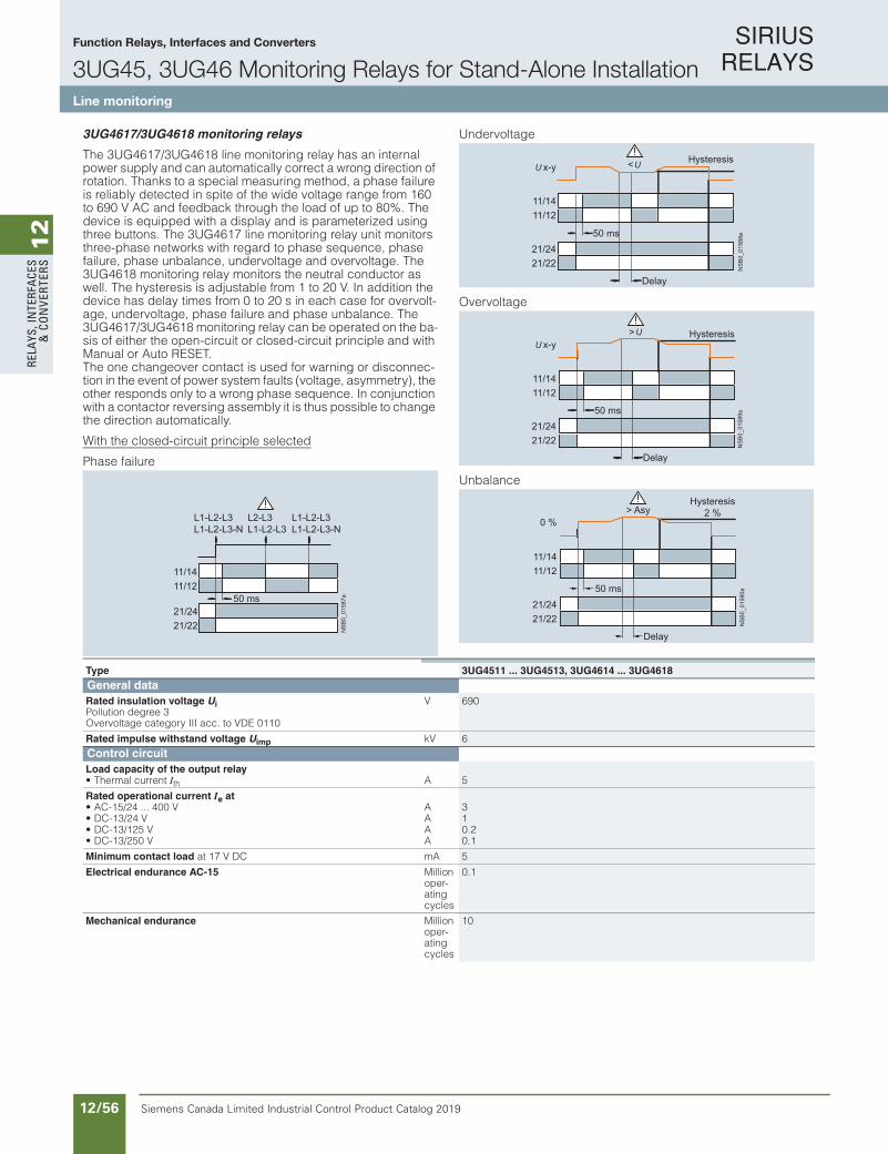
SIRIUS RELAYS
Siemens Canada Limited Industrial Control Product Catalog 201912/56
12
RELA
YS, I
NTE
RFA
CES
& C
ON
VERT
ERS
Siemens / Industrial Controls Previous folio: IC10 11/35
Function Relays, Interfaces and Converters
3UG45, 3UG46 Monitoring Relays for Stand-Alone InstallationLine monitoring
10/84 Siemens IC 10 · 2018
RelaysSIRIUS 3UG45, 3UG46 Monitoring Relays for Stand-Alone Installation
Line monitoring
10
3UG4617/3UG4618 monitoring relays
The 3UG4617/3UG4618 line monitoring relay has an internal power supply and can automatically correct a wrong direction of rotation. Thanks to a special measuring method, a phase failure is reliably detected in spite of the wide voltage range from 160 to 690 V AC and feedback through the load of up to 80%. The device is equipped with a display and is parameterized using three buttons. The 3UG4617 line monitoring relay unit monitors three-phase networks with regard to phase sequence, phase failure, phase unbalance, undervoltage and overvoltage. The 3UG4618 monitoring relay monitors the neutral conductor as well. The hysteresis is adjustable from 1 to 20 V. In addition the device has delay times from 0 to 20 s in each case for overvolt-age, undervoltage, phase failure and phase unbalance. The 3UG4617/3UG4618 monitoring relay can be operated on the ba-sis of either the open-circuit or closed-circuit principle and with Manual or Auto RESET. The one changeover contact is used for warning or disconnec-tion in the event of power system faults (voltage, asymmetry), the other responds only to a wrong phase sequence. In conjunction with a contactor reversing assembly it is thus possible to change the direction automatically.
With the closed-circuit principle selected
Phase failure
Undervoltage
Overvoltage
Unbalance
NS
B0_
0158
7a
11/14
50 ms11/12
21/2421/22
L1-L2-L3L1-L2-L3-N
L2-L3L1-L2-L3
L1-L2-L3L1-L2-L3-N
NS
B0_
0158
8a
11/14
50 ms
11/12
21/2421/22
<x-yHysteresis
Delay
NS
B0_
0158
9a
11/14
50 ms
11/12
21/2421/22
x-y> Hysteresis
Delay
NS
B0_
0159
0a
11/14
50 ms
11/12
21/2421/22
> Asy0 %
Hysteresis2 %
Delay
Type 3UG4511 ... 3UG4513, 3UG4614 ... 3UG4618General dataRated insulation voltage UiPollution degree 3Overvoltage category III acc. to VDE 0110
V 690
Rated impulse withstand voltage Uimp kV 6Control circuitLoad capacity of the output relay• Thermal current Ith A 5
Rated operational current Ie at• AC-15/24 ... 400 V A 3• DC-13/24 V A 1• DC-13/125 V A 0.2• DC-13/250 V A 0.1
Minimum contact load at 17 V DC mA 5
Electrical endurance AC-15 Million oper-ating cycles
0.1
Mechanical endurance Million oper-ating cycles
10
IC10_10_08.fm Page 84 Thursday, February 22, 2018 9:50 PM

SIRIUS RELAYS
Siemens Canada Limited Industrial Control Product Catalog 2019 12/57
12
RELAYS, IN
TERFACES
& CO
NVERTERS
Siemens / Industrial Controls Previous folio: IC10 11/36
Function Relays, Interfaces and Converters
3UG45, 3UG46 Monitoring Relays for Stand-Alone InstallationLine monitoring
10/85Siemens IC 10 · 2018* You can order this quantity or a multiple thereof.Illustrations are approximate
RelaysSIRIUS 3UG45, 3UG46 Monitoring Relays for Stand-Alone Installation
Line monitoring
10
Selection and ordering data
PU (UNIT, SET, M) = 1PKG* = 1 UNITPG = 41H
Function available
-- Function not available1) Absolute limit values.2) 1 CO contact each and one tripping delay time each for Umin and Umax.3) 1 CO contact each for power system fault and phase sequence correction.
For accessories, see page 10/111.
Adjustable hysteresis
Under-voltage detec-tion
Over-voltage detec-tion
Stabiliza-tion time adjustable stDEL
Tripping delay time adjustable Del
Version of auxiliary contacts
Measurable line voltage1)
SD Screw terminals
SD Spring-type terminals
s sCO contact V d
Article No. Priceper PU d
Article No. Priceper PU
Monitoring of phase sequenceAuto RESET
-- -- -- -- -- 1 160 … 260 AC 2 3UG4511-1AN20 2 3UG4511-2AN202 2 3UG4511-1BN20 2 3UG4511-2BN20
1 320 … 500 AC 2 3UG4511-1AP20 2 3UG4511-2AP202 2 3UG4511-1BP20 2 3UG4511-2BP20
1 420 … 690 AC 2 3UG4511-1AQ20 5 3UG4511-2AQ202 2 3UG4511-1BQ20 5 3UG4511-2BQ20
Monitoring of phase sequence, phase failure and phase unbalanceAuto RESET, closed-circuit principle, unbalance threshold permanently 10%
-- -- -- -- -- 1 160 … 690 AC 2 3UG4512-1AR20 2 3UG4512-2AR202 2 3UG4512-1BR20 2 3UG4512-2BR20
Monitoring of phase sequence, phase failure, unbalance and undervoltage Analogically adjustable, Auto RESET, closed-circuit principle, asymmetry and undervoltage threshold permanently 20%
5% of set value
-- -- 0.1 … 20 2 160 … 690 AC 2 3UG4513-1BR20 2 3UG4513-2BR20
Digitally adjustable, Auto RESET or Manual RESET, open-circuit or closed-circuit principle, asymmetry threshold 0 or 5 ... 20%
adjustable 1 ... 20 V
-- 0.1 ... 20 0.1 … 20 2 160 … 690 AC 2 3UG4614-1BR20 2 3UG4614-2BR20
Monitoring of phase sequence, phase failure, overvoltage and undervoltage Digitally adjustable, Auto RESET or Manual RESET, open-circuit or closed-circuit principle
adjustable 1 ... 20 V
-- 0.1 … 202) 22) 160 … 690 AC 2 3UG4615-1CR20 2 3UG4615-2CR20
Monitoring of phase sequence, phase and N conductor failure, overvoltage and undervoltage Digitally adjustable, Auto RESET or Manual RESET, open-circuit or closed-circuit principle
adjustable 1 ... 20 V
-- 0.1 … 202) 22) 90… 400 AC against N
2 3UG4616-1CR20 2 3UG4616-2CR20
Automatic correction of the direction of rotation in case of wrong phase sequence, phase failure, unbalance, overvoltage and undervoltageDigitally adjustable, Auto RESET or Manual RESET, open-circuit or closed-circuit principle, asymmetry threshold 0 or 5 ... 20%
adjustable 1 ... 20 V
-- 0.1 … 20 23) 160 … 690 AC 2 3UG4617-1CR20 2 3UG4617-2CR20
Automatic correction of the direction of rotation in case of wrong phase sequence, phase and N conductor failure, phase unbalance, overvoltage and undervoltageDigitally adjustable, Auto RESET or Manual RESET, open-circuit or closed-circuit principle, asymmetry threshold 0 or 5 ... 20%
adjustable 1 ... 20 V
-- 0.1 … 20 23) 90 … 400 AC against N
2 3UG4618-1CR20 2 3UG4618-2CR20
3UG4511-2BP203UG4511-1AP20 3UG4615-1CR20 3UG4616-1CR20 3UG4512-2BR203UG4617-1CR20 3UG4618-1CR20
IC10_10_08.fm Page 85 Thursday, February 22, 2018 9:50 PM
For accessories, see page 12/83

SIRIUS RELAYS
Siemens Canada Limited Industrial Control Product Catalog 201912/58
12
RELA
YS, I
NTE
RFA
CES
& C
ON
VERT
ERS
10/86 Siemens IC 10 · 2018
RelaysSIRIUS 3UG45, 3UG46 Monitoring Relays for Stand-Alone Installation
Voltage monitoring
10
Overview
SIRIUS 3UG4631 monitoring relay
The relays monitor single-phase AC voltages (rms value) and DC voltages against the set threshold value for overshoot and undershoot. The devices differ with regard to their power supply (internal or external).
Benefits
• Versions with wide voltage supply range• Variably adjustable to overshoot, undershoot or range
monitoring• Freely configurable delay times and RESET
response• Width 22.5 mm• Display of ACTUAL value and status messages• All versions with removable terminals• All versions with screw or spring-type terminals
Application
• Protection of a plant against destruction due to overvoltage• Switch-on of a plant at a defined voltage and higher• Protection from undervoltage due to overloaded control
supply voltages, particularly with battery power• Threshold switch for analog signals from 0.1 to 10 V
Technical specifications
3UG4631/3UG4632 monitoring relays
The 3UG4631/3UG4632 voltage monitoring relay is supplied with an auxiliary voltage of 24 V AC/DC or 24 to 240 V AC/DC and performs overshoot, undershoot or range monitoring of the voltage depending on parameterization. The device is equipped with a display and is parameterized using three buttons.
The measuring range extends from 0.1 to 60 V or 10 to 600 V AC/DC. The threshold values for overshoot or undershoot can be freely configured within this range. If one of these thresh-old values is reached, the output relay responds according to the set principle of operation as soon as the delay time has elapsed. This delay time UDel can be set from 0.1 to 20 s.The hysteresis can be set from 0.1 to 30 V or 0.1 to 300 V. The device can be operated on the basis of either the open-circuit or closed-circuit principle and with Manual or Auto RESET. One output changeover contact is available as signaling contact.
With the closed-circuit principle selected
Overvoltage
Undervoltage
Range monitoring
11/1411/12
A1-A2
>
= 0 Hysteresis
Delay
NS
B0_
0158
1a
11/1411/12
A1-A2
<
= 0
Hysteresis
Delay
NS
B0_
0158
2a
> <
Hysteresis
Hysteresis
Delay DelayDelay = Delay
NS
B0_
0158
3b
11/1411/12
A1-A2
IC10_10_08.fm Page 86 Thursday, February 22, 2018 9:50 PM
Function Relays, Interfaces and Converters
3UG45, 3UG46 Monitoring Relays for Stand-Alone InstallationVoltage monitoring
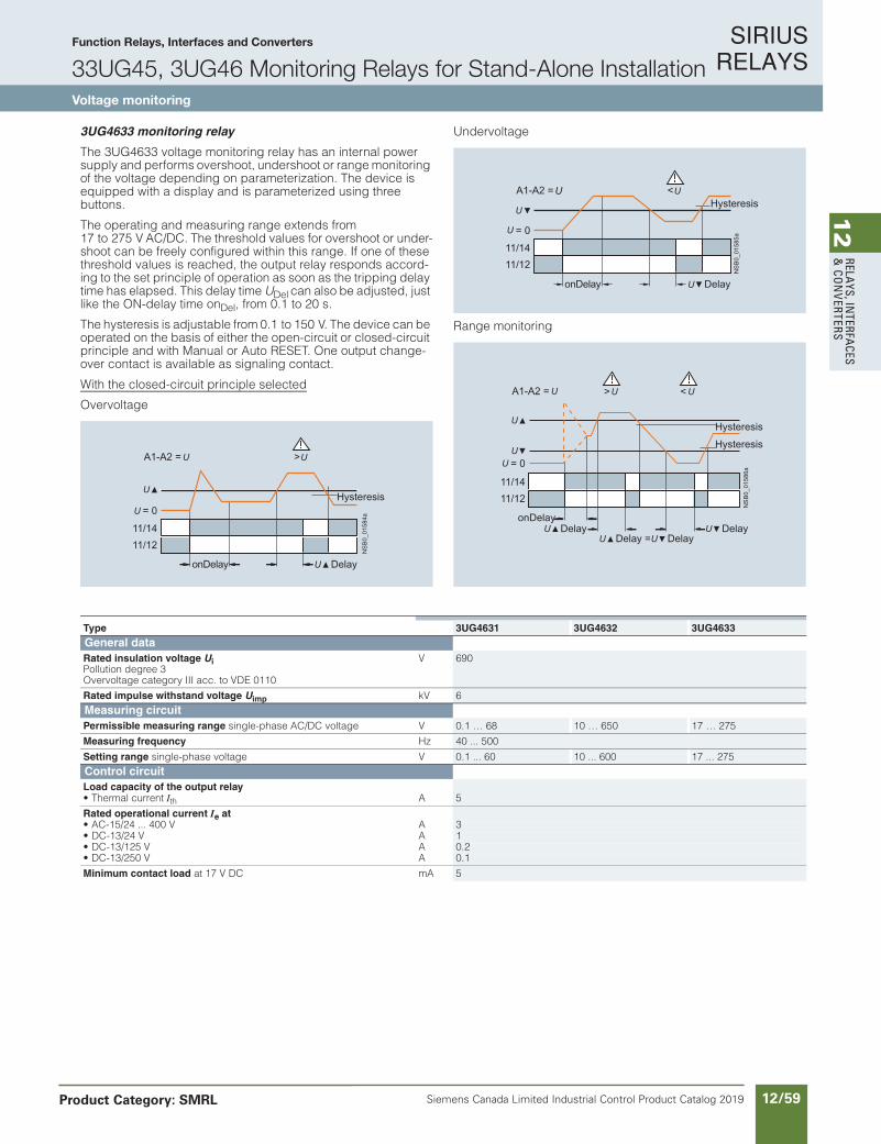
SIRIUS RELAYS
Siemens Canada Limited Industrial Control Product Catalog 2019 12/59
12
RELAYS, IN
TERFACES
& CO
NVERTERS
Siemens / Industrial Controls Previous folio: IC10 11/37
Function Relays, Interfaces and Converters
33UG45, 3UG46 Monitoring Relays for Stand-Alone InstallationVoltage monitoring
Product Category: SMRL
10/87Siemens IC 10 · 2018
RelaysSIRIUS 3UG45, 3UG46 Monitoring Relays for Stand-Alone Installation
Voltage monitoring
10
3UG4633 monitoring relay
The 3UG4633 voltage monitoring relay has an internal power supply and performs overshoot, undershoot or range monitoring of the voltage depending on parameterization. The device is equipped with a display and is parameterized using three buttons.
The operating and measuring range extends from 17 to 275 V AC/DC. The threshold values for overshoot or under-shoot can be freely configured within this range. If one of these threshold values is reached, the output relay responds accord-ing to the set principle of operation as soon as the tripping delay time has elapsed. This delay time UDel can also be adjusted, just like the ON-delay time onDel, from 0.1 to 20 s.
The hysteresis is adjustable from 0.1 to 150 V. The device can be operated on the basis of either the open-circuit or closed-circuit principle and with Manual or Auto RESET. One output change-over contact is available as signaling contact.
With the closed-circuit principle selected
Overvoltage
Undervoltage
Range monitoring
NS
B0_
0158
4a
11/1411/12
= 0
A1-A2 = >
Hysteresis
DelayonDelay
11/1411/12
= 0
A1-A2 = <Hysteresis
DelayonDelay
NS
B0_
0158
5a
>
11/1411/12
<A1-A2 =
= 0
Hysteresis
Hysteresis
DelayonDelay
Delay =Delay
Delay
NS
B0_
0158
6a
Type 3UG4631 3UG4632 3UG4633General dataRated insulation voltage UiPollution degree 3Overvoltage category III acc. to VDE 0110
V 690
Rated impulse withstand voltage Uimp kV 6Measuring circuitPermissible measuring range single-phase AC/DC voltage V 0.1 … 68 10 … 650 17 … 275
Measuring frequency Hz 40 ... 500
Setting range single-phase voltage V 0.1 ... 60 10 ... 600 17 ... 275Control circuitLoad capacity of the output relay• Thermal current Ith A 5
Rated operational current Ie at• AC-15/24 ... 400 V A 3• DC-13/24 V A 1• DC-13/125 V A 0.2• DC-13/250 V A 0.1
Minimum contact load at 17 V DC mA 5
IC10_10_08.fm Page 87 Thursday, February 22, 2018 9:50 PM
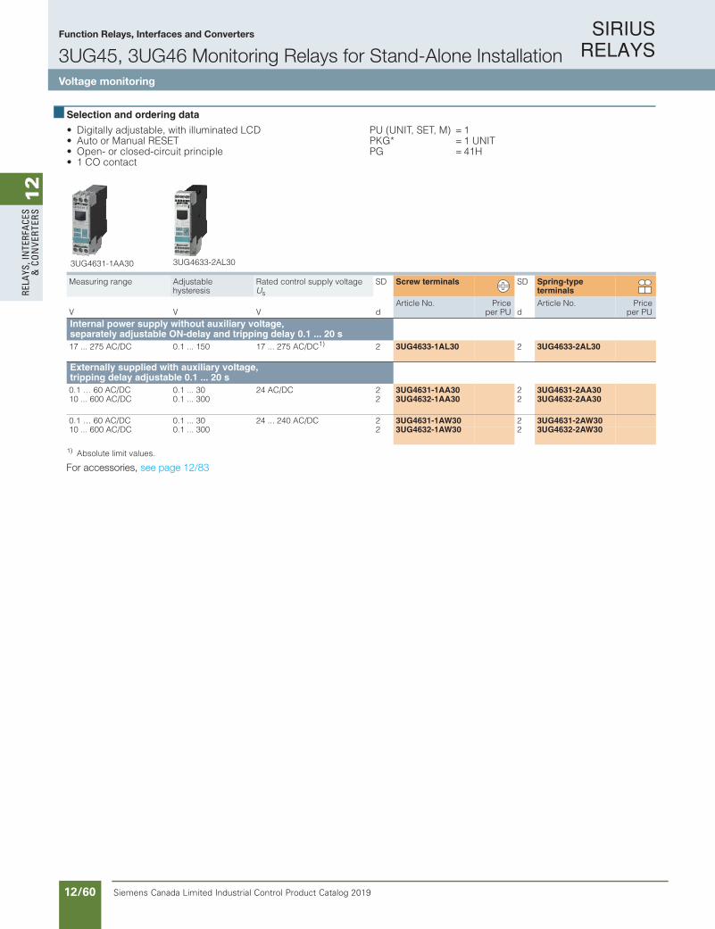
SIRIUS RELAYS
Siemens Canada Limited Industrial Control Product Catalog 201912/60
12
RELA
YS, I
NTE
RFA
CES
& C
ON
VERT
ERS
Siemens / Industrial Controls Previous folio: IC10 11/38
Function Relays, Interfaces and Converters
3UG45, 3UG46 Monitoring Relays for Stand-Alone InstallationVoltage monitoring
10/88 Siemens IC 10 · 2018* You can order this quantity or a multiple thereof.
Illustrations are approximate
RelaysSIRIUS 3UG45, 3UG46 Monitoring Relays for Stand-Alone Installation
Voltage monitoring
10
Selection and ordering data
• Digitally adjustable, with illuminated LCD• Auto or Manual RESET• Open- or closed-circuit principle• 1 CO contact
PU (UNIT, SET, M) = 1PKG* = 1 UNITPG = 41H
1) Absolute limit values.
For accessories, see page 10/111.
Measuring range Adjustablehysteresis
Rated control supply voltage Us
SD Screw terminals SD Spring-type terminals
V V V dArticle No. Price
per PU dArticle No. Price
per PUInternal power supply without auxiliary voltage, separately adjustable ON-delay and tripping delay 0.1 ... 20 s 17 ... 275 AC/DC 0.1 ... 150 17 ... 275 AC/DC1) 2 3UG4633-1AL30 2 3UG4633-2AL30
Externally supplied with auxiliary voltage, tripping delay adjustable 0.1 ... 20 s0.1 … 60 AC/DC 0.1 ... 30 24 AC/DC 2 3UG4631-1AA30 2 3UG4631-2AA3010 ... 600 AC/DC 0.1 ... 300 2 3UG4632-1AA30 2 3UG4632-2AA30
0.1 … 60 AC/DC 0.1 ... 30 24 ... 240 AC/DC 2 3UG4631-1AW30 2 3UG4631-2AW3010 ... 600 AC/DC 0.1 ... 300 2 3UG4632-1AW30 2 3UG4632-2AW30
3UG4631-1AA30 3UG4633-2AL30
IC10_10_08.fm Page 88 Thursday, February 22, 2018 9:50 PM
For accessories, see page 12/83
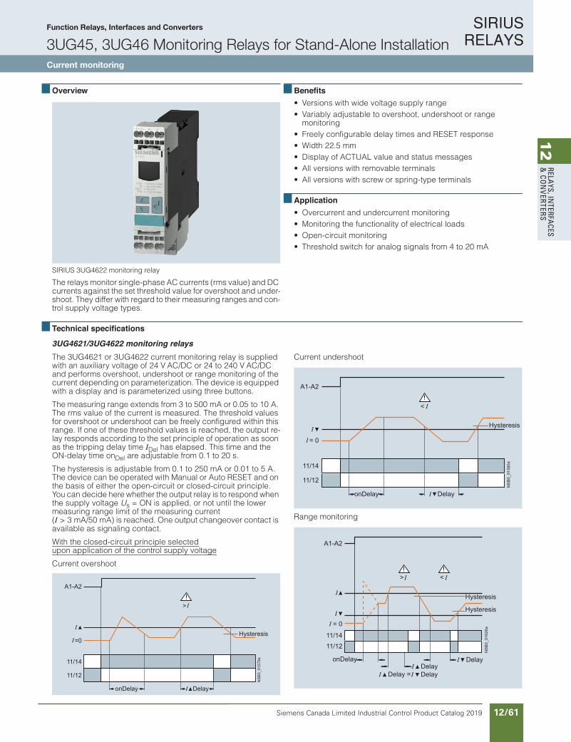
SIRIUS RELAYS
Siemens Canada Limited Industrial Control Product Catalog 2019 12/61
12
RELAYS, IN
TERFACES
& CO
NVERTERS
Siemens / Industrial Controls Previous folio: IC10 11/39
10/89Siemens IC 10 · 2018
RelaysSIRIUS 3UG45, 3UG46 Monitoring Relays for Stand-Alone Installation
Current monitoring
10
Overview
SIRIUS 3UG4622 monitoring relay
The relays monitor single-phase AC currents (rms value) and DC currents against the set threshold value for overshoot and under-shoot. They differ with regard to their measuring ranges and con-trol supply voltage types.
Benefits• Versions with wide voltage supply range• Variably adjustable to overshoot, undershoot or range
monitoring• Freely configurable delay times and RESET response• Width 22.5 mm• Display of ACTUAL value and status messages• All versions with removable terminals• All versions with screw or spring-type terminals
Application• Overcurrent and undercurrent monitoring• Monitoring the functionality of electrical loads• Open-circuit monitoring• Threshold switch for analog signals from 4 to 20 mA
Technical specifications
3UG4621/3UG4622 monitoring relays The 3UG4621 or 3UG4622 current monitoring relay is supplied with an auxiliary voltage of 24 V AC/DC or 24 to 240 V AC/DC and performs overshoot, undershoot or range monitoring of the current depending on parameterization. The device is equipped with a display and is parameterized using three buttons.
The measuring range extends from 3 to 500 mA or 0.05 to 10 A. The rms value of the current is measured. The threshold values for overshoot or undershoot can be freely configured within this range. If one of these threshold values is reached, the output re-lay responds according to the set principle of operation as soon as the tripping delay time IDel has elapsed. This time and the ON-delay time onDel are adjustable from 0.1 to 20 s.
The hysteresis is adjustable from 0.1 to 250 mA or 0.01 to 5 A. The device can be operated with Manual or Auto RESET and on the basis of either the open-circuit or closed-circuit principle. You can decide here whether the output relay is to respond when the supply voltage Us = ON is applied, or not until the lower measuring range limit of the measuring current (I > 3 mA/50 mA) is reached. One output changeover contact is available as signaling contact.
With the closed-circuit principle selectedupon application of the control supply voltage
Current overshoot
Current undershoot
Range monitoring
11/14
A1-A2
11/12
=0
>
Hysteresis
DelayonDelay
NS
B0_
0157
9a
<
Hysteresis
DelayonDelay
11/14
A1-A2
11/12
= 0
NS
B0_
0158
0a
> <
Hysteresis
Hysteresis
DelayDelayDelayDelay =
onDelay
NS
B0_
0162
6a
11/1411/12
A1-A2
= 0
IC10_10_08.fm Page 89 Thu rsday, February 22, 2018 9:50 PM
Function Relays, Interfaces and Converters
3UG45, 3UG46 Monitoring Relays for Stand-Alone InstallationCurrent monitoring
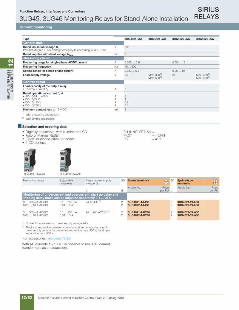
SIRIUS RELAYS
Siemens Canada Limited Industrial Control Product Catalog 201912/62
12
RELA
YS, I
NTE
RFA
CES
& C
ON
VERT
ERS
Siemens / Industrial Controls Previous folio: IC10 11/40
Function Relays, Interfaces and Converters
3UG45, 3UG46 Monitoring Relays for Stand-Alone InstallationCurrent monitoring
10/90 Siemens IC 10 · 2018* You can order this quantity or a multiple thereof.
Illustrations are approximate
RelaysSIRIUS 3UG45, 3UG46 Monitoring Relays for Stand-Alone Installation
Current monitoring
10
1) With protective separation.2) With simple separation.
Selection and ordering data
• Digitally adjustable, with illuminated LCD• Auto or Manual RESET• Open- or closed-circuit principle• 1 CO contact
PU (UNIT, SET, M) = 1PKG* = 1 UNITPG = 41H
1) No electrical separation. Load supply voltage 24 V.2) Electrical separation between control circuit and measuring circuit.
Load supply voltage for protective separation max. 300 V, for simple separation max. 500 V.
For accessories, see page 10/111.
With AC currents I > 10 A it is possible to use 4NC current transformers as an accessory.
Type 3UG4621-.AA 3UG4621-.AW 3UG4622-.AA 3UG4622-.AWGeneral dataRated insulation voltage UiPollution degree 3; overvoltage category III according to VDE 0110
V 690
Rated impulse withstand voltage Uimp kV 6Measuring circuitMeasuring range for single-phase AC/DC current A 0.003 … 0.6 0.05 … 15
Measuring frequency Hz 40 ... 500
Setting range for single-phase current A 0.003 ... 0.5 0.05 ... 10
Load supply voltage V 24 Max. 3001)
Max. 5002)24 Max. 3001)
Max. 5002)
Control circuitLoad capacity of the output relay• Thermal current Ith A 5
Rated operational current Ie at• AC-15/24 ... 400 V A 3• DC-13/24 V A 1• DC-13/125 V A 0.2• DC-13/250 V A 0.1
Minimum contact load at 17 V DC mA 5
Measuring range Adjustablehysteresis
Rated control supplyvoltage Us
SD Screw terminals SD Spring-type terminals
V dArticle No. Price
per PU dArticle No. Price
per PUMonitoring of undercurrent and overcurrent, start up delay and tripping delay times can be adjusted separately 0.1 ... 20 s 3 … 500 mA AC/DC 0.1 ... 250 mA 24 AC/DC 1) 2 3UG4621-1AA30 2 3UG4621-2AA300.05 … 10 A AC/DC 0.01 ... 5 A 2 3UG4622-1AA30 2 3UG4622-2AA30
3 … 500 mA AC/DC 0.1 ... 250 mA 24 ... 240 AC/DC 2) 2 3UG4621-1AW30 2 3UG4621-2AW300.05 … 10 A AC/DC 0.01 ... 5 A 2 3UG4622-1AW30 2 3UG4622-2AW30
3UG4621-1AA30 3UG4622-2AW30
IC10_10_08.fm Page 90 Thursday, February 22, 2018 9:50 PM
For accessories, see page 12/83
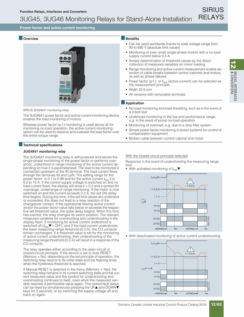
SIRIUS RELAYS
Siemens Canada Limited Industrial Control Product Catalog 2019 12/63
12
RELAYS, IN
TERFACES
& CO
NVERTERS
Siemens / Industrial Controls Previous folio: IC10 11/41
Function Relays, Interfaces and Converters
3UG45, 3UG46 Monitoring Relays for Stand-Alone InstallationPower factor and active current monitoring
10/91Siemens IC 10 · 2018
RelaysSIRIUS 3UG45, 3UG46 Monitoring Relays for Stand-Alone Installation
Power factor and active current monitoring
10
Overview
SIRIUS 3UG4641 monitoring relay
The 3UG4641 power factor and active current monitoring device enables the load monitoring of motors.
Whereas power factor (p.f.) monitoring is used above all for monitoring no-load operation, the active current monitoring option can be used to observe and evaluate the load factor over the entire torque range.
Benefits• Can be used worldwide thanks to wide voltage range from
90 to 690 V (absolute limit values)• Monitoring of even small single-phase motors with a no-load
supply current below 0.5 A• Simple determination of threshold values by the direct
collection of measured variables on motor loading• Range monitoring and active current measurement enable de-
tection of cable breaks between control cabinets and motors, as well as phase failures
• Power factor (p.f.) or Ires (active current) can be selected as the measurement principle
• Width 22.5 mm• All versions with removable terminals
Application• No-load monitoring and load shedding, such as in the event of
a V-belt tear• Underload monitoring in the low-end performance range,
e.g. in the event of pump no-load operation• Monitoring of overload, e.g. due to a dirty filter system• Simple power factor monitoring in power systems for control of
compensation equipment• Broken cable between control cabinet and motor
Technical specifications
3UG4641 monitoring relayThe 3UG4641 monitoring relay is self-powered and serves the single-phase monitoring of the power factor or performs over-shoot, undershoot or range monitoring of the active current de-pending on how it is parameterized. The load to be monitored is connected upstream of the IN terminal. The load current flows through the terminals IN and Ly/N. The setting range for the power factor is 0.1 to 0.99 and for the active current Ires it is 0.2 to 10 A. If the control supply voltage is switched on and no load current flows, the display will show I < 0.2 and a symbol for overrange, underrange or range monitoring. If the motor is now switched on and the current exceeds 0.2 A, the set ON-delay time begins. During this time, if the set limit values are undershot or exceeded, this does not lead to a relay reaction of the changeover contact. If the operational flowing active current and/or the power factor value falls below or exceeds the respec-tive set threshold value, the spike delay begins. When this time has expired, the relay changes its switch position. The relevant measured variables for overshooting and undershooting in the display flash. If monitoring for active current undershoot is switched off (Ires = OFF), and if the load current undershoots the lower measuring range threshold (0.2 A), the CO contacts remain unchanged. If a threshold value is set for the monitoring of active current undershooting, then undershooting of the measuring range threshold (0.2 A) will result in a response of the CO contacts.
The relay operates either according to the open-circuit or closed-circuit principle. If the device is set to Auto RESET (Memory = No), depending on the set principle of operation, the switching relay returns to its initial state and the flashing ends when the hysteresis threshold is reached.
If Manual RESET is selected in the menu (Memory = Yes), the switching relay remains in its current switching state and the cur-rent measured value and the symbol for undershooting and overshooting continues to flash, even when the measured vari-able reaches a permissible value again. This stored fault status can be reset by simultaneously pressing the UP and DOWN keys for 2 seconds, or by switching the supply voltage off and back on again.
With the closed-circuit principle selected
Response in the event of undershooting the measuring range limit• With activated monitoring of Ires
• With deactivated monitoring of active current undershooting
21/22
21/24
11/12
11/14
Lx-Ly/N
I = 0,2 A
I = 0
I < 0,2 A
I res
onDelayonDelay
b85610_0B
SN
< 0,2 A
onDelayonDelay
b71910_0BSN
21/22
21/24
11/12
11/14
Lx-Ly/N
= 0,2 A
= 0
res = off
IC10_10_08.fm Page 91 Thu rsday, February 22, 2018 9:50 PM
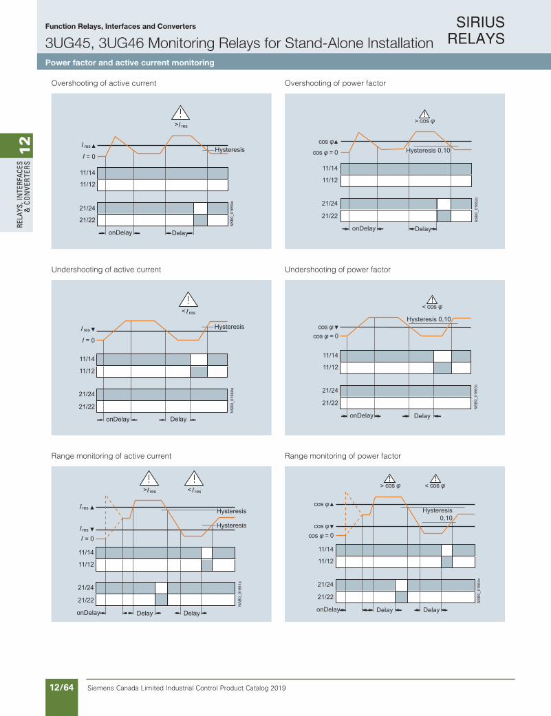
SIRIUS RELAYS
Siemens Canada Limited Industrial Control Product Catalog 201912/64
12
RELA
YS, I
NTE
RFA
CES
& C
ON
VERT
ERS
Siemens / Industrial Controls Previous folio: IC10 11/42
Function Relays, Interfaces and Converters
3UG45, 3UG46 Monitoring Relays for Stand-Alone InstallationPower factor and active current monitoring
10/92 Siemens IC 10 · 2018
RelaysSIRIUS 3UG45, 3UG46 Monitoring Relays for Stand-Alone Installation
Power factor and active current monitoring
10
Overshooting of active current
Undershooting of active current
Range monitoring of active current
Overshooting of power factor
Undershooting of power factor
Range monitoring of power factor
21/24
21/22
11/14
11/12
> res
= 0
res
DelayonDelay
Hysteresis
NS
B0_
0165
9a
21/24
21/22
11/14
11/12
< res
= 0
res
DelayonDelay
Hysteresis
NS
B0_
0166
0a
< res> res
DelayonDelay Delay
Hysteresis
Hysteresis
NS
B0_
0166
1a21/24
21/22
11/14
11/12
= 0
res
res
21/24
21/22
11/14
11/12
cos φ = 0
cos φ
DelayonDelay
Hysteresis 0,10
NS
B0_
0166
2c
> cos φ
cos φ = 0cos φ
< cos φ
Hysteresis 0,10
DelayonDelay
NS
B0_
0166
3c21/24
21/22
11/14
11/12
21/24
21/22
11/14
11/12
< cos φ
cos φ = 0
Hysteresis0,10
DelayonDelay Delay
NS
B0_
0166
4c
> cos φ
cos φ
cos φ
IC10_10_08.fm Page 92 Thursday, February 22, 2018 9:50 PM
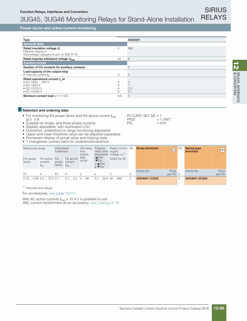
SIRIUS RELAYS
Siemens Canada Limited Industrial Control Product Catalog 2019 12/65
12
RELAYS, IN
TERFACES
& CO
NVERTERS
Siemens / Industrial Controls Previous folio: IC10 11/43
Function Relays, Interfaces and Converters
3UG45, 3UG46 Monitoring Relays for Stand-Alone InstallationPower factor and active current monitoring
10/93Siemens IC 10 · 2018* You can order this quantity or a multiple thereof.Illustrations are approximate
RelaysSIRIUS 3UG45, 3UG46 Monitoring Relays for Stand-Alone Installation
Power factor and active current monitoring
10
Selection and ordering data
• For monitoring the power factor and the active current Ires (p.f. x I)
• Suitable for single- and three-phase currents• Digitally adjustable, with illuminated LCD• Overshoot, undershoot or range monitoring adjustable• Upper and lower threshold value can be adjusted separately• Permanent display of actual value and tripping state• 1 changeover contact each for undershoot/overshoot
PU (UNIT, SET, M) = 1PKG* = 1 UNITPG = 41H
1) Absolute limit values.
For accessories, see page 10/111.
With AC active currents Ires > 10 A it is possible to use 4NC current transformers as an accessory, see Catalog LV 10.
Type 3UG4641General dataRated insulation voltage UiPollution degree 3Overvoltage category III acc. to VDE 0110
V 690
Rated impulse withstand voltage Uimp kV 6Control circuitNumber of CO contacts for auxiliary contacts 2
Load capacity of the output relay• Thermal current Ith A 5
Rated operational current Ie at• AC-15/24 ... 400 V A 3• DC-13/24 V A 1• DC-13/125 V A 0.2• DC-13/250 V A 0.1
Minimum contact load at 17 V DC mA 5
Measuring range Adjustablehysteresis
ON-delay time adjust-able onDel
Tripping delay time adjustable IDel/IDel, Del/ Del
Rated control supply voltage Us
1)
SD Screw terminals SD Spring-type terminals
For power factor
For active current Ires
For power factor
For active current Ires
50/60 Hz AC
P.f. A P.f. A s s V dArticle No. Price
per PU dArticle No. Price
per PU
0.10 ... 0.99 0.2 ... 10.0 0.1 0.1 ... 2.0 0 ... 99 0.1 ... 20.0 90 ... 690 2 3UG4641-1CS20 2 3UG4641-2CS20
IC10_10_08.fm Page 93 Thursday, February 22, 2018 9:50 PM

SIRIUS RELAYS
Siemens Canada Limited Industrial Control Product Catalog 201912/66
12
RELA
YS, I
NTE
RFA
CES
& C
ON
VERT
ERS
Siemens / Industrial Controls Previous folio: IC10 11/44
Function Relays, Interfaces and Converters
3UG45, 3UG46 Monitoring Relays for Stand-Alone InstallationResidual-current monitoring relays
10/94 Siemens IC 10 · 2018
RelaysSIRIUS 3UG45, 3UG46 Monitoring Relays for Stand-Alone InstallationResidual-Current Monitoring
Residual-current monitoring relays
10
Overview
SIRIUS 3UG4625 monitoring relay
The 3UG4625 residual-current monitoring relays are used in conjunction with the 3UL23 residual-current transformers for monitoring plants in which higher residual currents are increas-ingly expected due to ambient conditions. Monitoring encom-passes pure AC residual currents or AC residual currents with a pulsating DC fault current component (transformer type A in accordance with DIN VDE 0100-530/IEC TR 60755).
Benefits
• Worldwide use thanks to wide voltage range from 24 to 240 V AC/DC
• High measuring accuracy of ± 7.5%• Permanent self-monitoring• Variable threshold values for warning and disconnection• Freely configurable delay times and RESET response• Permanent display of the actual value and fault diagnostics via
the display• High level of flexibility and space saving through installation of
the transformer inside or outside the control cabinet• Width 22.5 mm• All versions with removable terminals• All versions with screw or spring-type terminals
Application
Monitoring of plants in which residual currents can occur, e.g. due to dust deposits or moisture, porous cables and leads, or capacitive residual currents.
Technical specifications
3UG4625 monitoring relays
The main conductor, and any neutral conductor to which a load is connected, are routed through the opening of the annular ring core of a residual-current transformer. A secondary winding is placed around this annular strip-wound core to which the moni-toring relay is connected.
If operation of a plant is fault-free, the sum of the inflowing and outward currents equals zero. No current is then induced in the secondary winding of the residual-current transformer.
However, if an insulation fault occurs downstream of the residual current operated circuit breaker, the sum of the inflowing cur-rents is greater than that of the outward currents. The differential current – i.e. the residual current – induces a secondary current in the secondary winding of the transformer. This current is eval-uated in the monitoring relay and is used on the one hand to dis-play the actual residual current and on the other, to switch the re-lay if the set warning or tripping threshold is overshot.
If the measured residual current exceeds the set warning value, the associated changeover contact instantly changes the switching state and an indication appears on the display.
If the measured residual current exceeds the set tripping value, the set delay time begins and the associated relay symbol flashes. On expiry of this time, the associated changeover con-tact changes the switching state.
ON-delay time for motor start
To be able to start a drive when a residual current is detected, the output relays switch to the OK state for an adjustable ON-delay time depending on the selected open-circuit principle or closed-circuit principle.
The changeover contacts do not react if the set threshold values are overshot during this period.
With the closed-circuit principle selected
Residual current monitoring with Auto RESET (Memory = no)
If the device is set to Auto RESET, the relay switches back to the OK state for the tripping value once the value falls below the set hysteresis threshold and the display stops flashing.
The associated relay changes its switching state if the value falls below the fixed hysteresis value of 5% of the set warning value.
Any overshoots are therefore not stored.
!
> > !
Hysteresis
= 0,02 A
Hysteresis = 5 %
onDelayonDelay
InitDelay
IC01
_002
25
A1-A2
11/14
11/12
21/24
21/22
= 0
IC10_10_08.fm Page 94 Thursday, February 22, 2018 9:50 PM
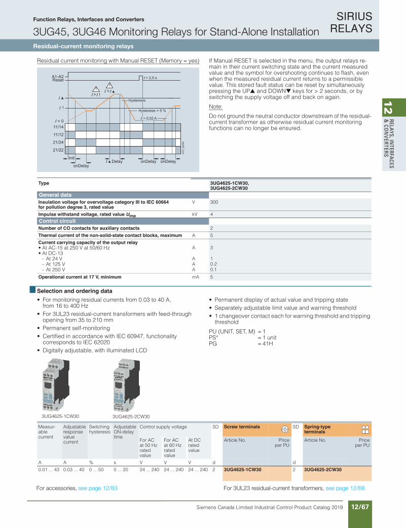
SIRIUS RELAYS
Siemens Canada Limited Industrial Control Product Catalog 2019 12/67
12
RELAYS, IN
TERFACES
& CO
NVERTERS
Function Relays, Interfaces and Converters
3UG45, 3UG46 Monitoring Relays for Stand-Alone InstallationResidual-current monitoring relays
10/95Siemens IC 10 · 2018* You can order this quantity or a multiple thereof.Illustrations are approximate
RelaysSIRIUS 3UG45, 3UG46 Monitoring Relays for Stand-Alone Installation
Residual-Current Monitoring
Residual-current monitoring relays
10
Residual current monitoring with Manual RESET (Memory = yes) If Manual RESET is selected in the menu, the output relays re-main in their current switching state and the current measured value and the symbol for overshooting continues to flash, even when the measured residual current returns to a permissible value. This stored fault status can be reset by simultaneously pressing the UP and DOWN keys for > 2 seconds, or by switching the supply voltage off and back on again.
Note:
Do not ground the neutral conductor downstream of the residual-current transformer as otherwise residual current monitoring functions can no longer be ensured.
Selection and ordering data • For monitoring residual currents from 0.03 to 40 A,
from 16 to 400 Hz• For 3UL23 residual-current transformers with feed-through
opening from 35 to 210 mm• Permanent self-monitoring• Certified in accordance with IEC 60947, functionality
corresponds to IEC 62020• Digitally adjustable, with illuminated LCD
• Permanent display of actual value and tripping state• Separately adjustable limit value and warning threshold• 1 changeover contact each for warning threshold and tripping
threshold
PU (UNIT, SET, M) = 1 PS* = 1 unit PG = 41H
For accessories, see page 10/111 ,sremrofsnart tnerruc-laudiser 32LU3 roF . see page 10/96.
!
> > !
Hysteresis
= 0,02 A
Hysteresis = 5 %
Delay onDelayonDelayonDelay
Init
t > 2,5 sA1-A2Reset
11/14
11/12
21/24
21/22
= 0
IC01
_002
26Type 3UG4625-1CW30,
3UG4625-2CW30General dataInsulation voltage for overvoltage category III to IEC 60664 for pollution degree 3, rated value
V 300
Impulse withstand voltage, rated value Uimp kV 4Control circuitNumber of CO contacts for auxiliary contacts 2
Thermal current of the non-solid-state contact blocks, maximum A 5
Current carrying capacity of the output relay• At AC-15 at 250 V at 50/60 Hz A 3• At DC-13
- At 24 V A 1- At 125 V A 0.2- At 250 V A 0.1
Operational current at 17 V, minimum mA 5
Measur-able current
Adjustable response value current
Switching hysteresis
Adjustable ON-delay time
Control supply voltage SD Screw terminals SD Spring-type terminals
For AC at 50 Hz rated value
For AC at 60 Hz rated value
At DC rated value
Article No. Priceper PU
Article No. Priceper PU
A A % s V V V d d
0.01 ... 43 0.03 ... 40 0 ... 50 0 ... 20 24 ... 240 24 ... 240 24 ... 240 2 3UG4625-1CW30 2 3UG4625-2CW30
3UG4625-1CW30 3UG4625-2CW30
IC10_10_08.fm Page 95 Thu rsday, February 22, 2018 9:50 PM
For accessories, see page 12/83 For 3UL23 residual-current transformers, see page 12/68.

SIRIUS RELAYS
Siemens Canada Limited Industrial Control Product Catalog 201912/68
12
RELA
YS, I
NTE
RFA
CES
& C
ON
VERT
ERS
10/96 Siemens IC 10 · 2018* You can order this quantity or a multiple thereof.
Illustrations are approximate
RelaysSIRIUS 3UG45, 3UG46 Monitoring Relays for Stand-Alone InstallationResidual-Current Monitoring
3UL23 residual-current transformers
10
Overview
SIRIUS 3UL23 residual-current transformer
The 3UL23 residual-current transformers detect residual cur-rents in machines and plants. They are suitable for pure AC re-sidual currents or AC residual currents with a pulsating DC fault current component (transformer type A in accordance with DIN VDE 0100-530/IEC TR 60755).
Together with the 3UG4625, 3UG4825 residual-current monitor-ing relays for IO-Link or the SIMOCODE 3UF motor management and control device they enable residual-current and ground-fault monitoring.
The 3UL2302-1A and 3UL2303-1A residual-current transformers with a feed-through opening from 35 to 55 mm can be mounted in conjunction with the 3UL2900 accessories on a TH 35 stan-dard mounting rail according to IEC 60715.
Selection and ordering data
Accessories
Diameter of the bushing opening Connectable cross-section of the connecting terminal
SD Screw terminals PU(UNIT,
SET, M)
PS* PG
mm mm2 dArticle No. Price
per PUResidual-current transformers (essential accessories for 3UG4625, 3UG4825)35 2.5 2 3UL2302-1A 1 1 unit 41H55 2.5 2 3UL2303-1A 1 1 unit 41H80 2.5 2 3UL2304-1A 1 1 unit 41H
110 2.5 2 3UL2305-1A 1 1 unit 41H140 2.5 2 3UL2306-1A 1 1 unit 41H210 4 2 3UL2307-1A 1 1 unit 41H
Version SD Article No. Priceper PU
PU(UNIT,
SET, M)
PS* PG
dAdapters
3UL2900
Adapters
For mounting onto standard railfor 3UL23 to diameter 55 mm
2 3UL2900 1 2 units 41H
IC10_10_08.fm Page 96 Thursday, February 22, 2018 9:50 PM
Function Relays, Interfaces and Converters
3UG45, 3UG46 Monitoring Relays for Stand-Alone Installation3UL23 residual-current transformers

SIRIUS RELAYS
Siemens Canada Limited Industrial Control Product Catalog 2019 12/69
12
RELAYS, IN
TERFACES
& CO
NVERTERS
10/97Siemens IC 10 · 2018
RelaysSIRIUS 3UG45, 3UG46 Monitoring Relays for Stand-Alone Installation
Insulation Monitoring
General data
10
Overview
SIRIUS 3UG458. insulation monitor
Insulation monitoring relays are used for monitoring the insula-tion resistance between ungrounded single or three-phase AC supplies and a protective conductor.
Ungrounded, i.e. isolated networks (IT networks) are always used where high demands are placed on the reliability of the power supply, e.g. emergency lighting systems. IT systems are supplied via an isolating transformer or by power supply sources such as batteries or a generator. While an initial insulation fault between a phase conductor and the ground effectively grounds the conductor, as a result no circuit has been closed, so it is pos-sible to continue work in safety (single-fault safety). However, the fault must be rectified as quickly as possible before a second insulation fault occurs (e.g. according to DIN VDE 0100-410). For this purpose insulation monitoring relays are used, which constantly measure the resistance to ground of the phase con-ductor and the neutral conductor, reporting a fault immediatelyif insulation resistance falls below the set value so that either a controlled shutdown can be performed or the fault can be recti-fied without interrupting the power supply.
Two device series• 3UG4581 insulation monitoring relays for ungrounded
AC networks• 3UG4582 and 3UG4583 insulation monitoring relays for
ungrounded DC and AC networks
Benefits
• Devices for AC and DC systems• All devices have a wide control supply voltage range• Direct connection to networks with mains voltages of up to
690 V AC and 1 000 V DC by means of a voltage reducer module
• For AC supply systems: Frequency range 15 to 400 Hz• Monitoring of broken conductors• Monitoring of setting errors• Safety in use thanks to integrated system test after startup• Option of resetting and testing (by means of button on front or
using control contact)• New predictive measurement principle allows very fast
response times
Application
IT networks are used, for example:• In emergency power supplies• In safety lighting systems• In industrial production facilities with high availability require-
ments (chemical industry, automobile manufacturing, printing plants)
• In shipping and railways• For mobile generators (aircraft)• For renewable energies, such as wind energy and
photovoltaic power plants• In the mining industry
IC10_10_09.fm Page 97 Thursday, February 22, 2018 8:50 PM
Function Relays, Interfaces and Converters
3UG45, 3UG46 Monitoring Relays for Stand-Alone InstallationInsulation monitoring
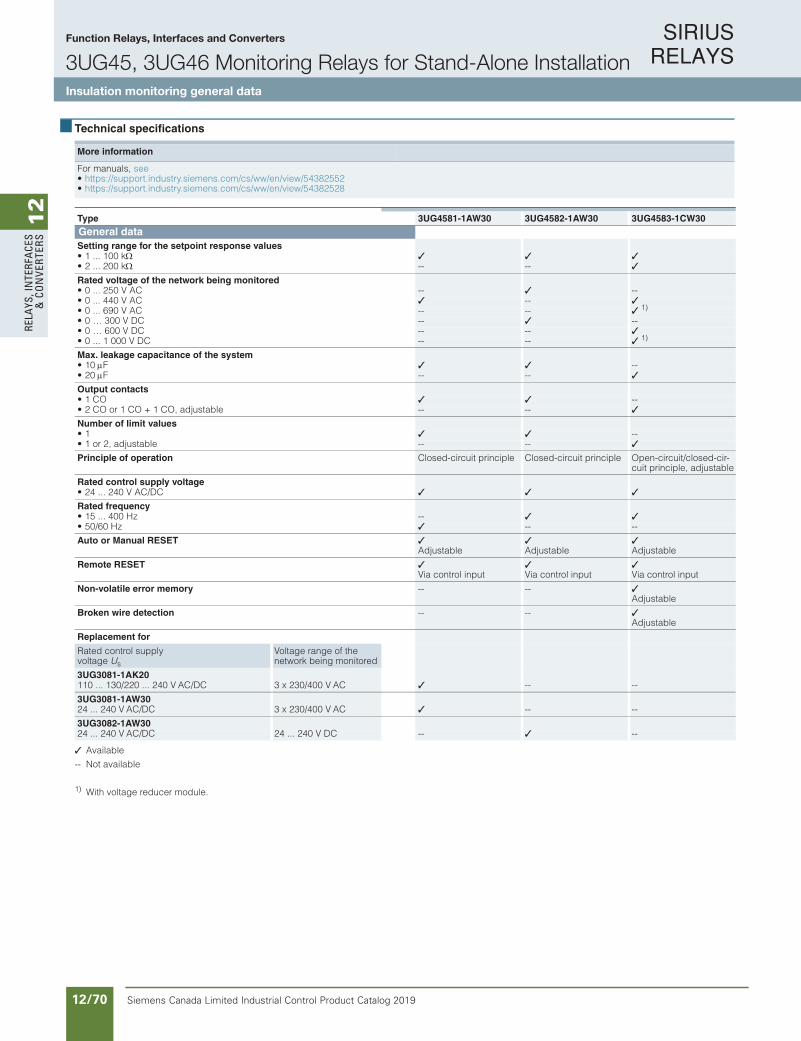
SIRIUS RELAYS
Siemens Canada Limited Industrial Control Product Catalog 201912/70
12
RELA
YS, I
NTE
RFA
CES
& C
ON
VERT
ERS
Function Relays, Interfaces and Converters
3UG45, 3UG46 Monitoring Relays for Stand-Alone InstallationInsulation monitoring general data
10/98 Siemens IC 10 · 2018
RelaysSIRIUS 3UG45, 3UG46 Monitoring Relays for Stand-Alone InstallationInsulation Monitoring
General data
10
Technical specifications
Available
-- Not available
1) With voltage reducer module.
More information
For manuals, see• https://support.industry.siemens.com/cs/ww/en/view/54382552• https://support.industry.siemens.com/cs/ww/en/view/54382528
Type 3UG4581-1AW30 3UG4582-1AW30 3UG4583-1CW30General dataSetting range for the setpoint response values• 1 ... 100 k • 2 ... 200 k -- --
Rated voltage of the network being monitored• 0 ... 250 V AC -- --• 0 ... 440 V AC -- • 0 ... 690 V AC -- -- 1) • 0 … 300 V DC -- --• 0 … 600 V DC -- -- • 0 ... 1 000 V DC -- -- 1)
Max. leakage capacitance of the system• 10F --• 20F -- --
Output contacts• 1 CO --• 2 CO or 1 CO + 1 CO, adjustable -- --
Number of limit values• 1 --• 1 or 2, adjustable -- --
Principle of operation Closed-circuit principle Closed-circuit principle Open-circuit/closed-cir-cuit principle, adjustable
Rated control supply voltage• 24 ... 240 V AC/DC
Rated frequency• 15 ... 400 Hz -- • 50/60 Hz -- --
Auto or Manual RESET Adjustable
Adjustable
Adjustable
Remote RESET Via control input
Via control input
Via control input
Non-volatile error memory -- -- Adjustable
Broken wire detection -- -- Adjustable
Replacement for
Rated control supplyvoltage Us
Voltage range of the network being monitored
3UG3081-1AK20110 ... 130/220 ... 240 V AC/DC 3 x 230/400 V AC -- --
3UG3081-1AW3024 ... 240 V AC/DC 3 x 230/400 V AC -- --
3UG3082-1AW3024 ... 240 V AC/DC 24 ... 240 V DC -- --
IC10_10_09.fm Page 98 Thursday, February 22, 2018 8:50 PM
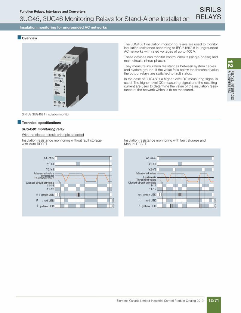
SIRIUS RELAYS
Siemens Canada Limited Industrial Control Product Catalog 2019 12/71
12
RELAYS, IN
TERFACES
& CO
NVERTERS
Function Relays, Interfaces and Converters
3UG45, 3UG46 Monitoring Relays for Stand-Alone InstallationInsulation monitoring for ungrounded AC networks
10/99Siemens IC 10 · 2018
RelaysSIRIUS 3UG45, 3UG46 Monitoring Relays for Stand-Alone Installation
Insulation Monitoring
For ungrounded AC networks
10
Overview
SIRIUS 3UG4581 insulation monitor
The 3UG4581 insulation monitoring relays are used to monitor insulation resistance according to IEC 61557-8 in ungrounded AC networks with rated voltages of up to 400 V.
These devices can monitor control circuits (single-phase) and main circuits (three-phase).
They measure insulation resistances between system cables and system ground. If the value falls below the threshold value, the output relays are switched to fault status.
In the case of 3UG4581 a higher-level DC measuring signal is used. The higher-level DC measuring signal and the resulting current are used to determine the value of the insulation resis-tance of the network which is to be measured.
Technical specifications
3UG4581 monitoring relay
With the closed-circuit principle selected
Insulation resistance monitoring without fault storage,with Auto RESET
Insulation resistance monitoring with fault storage andManual RESET
F
Closed-circuit principle
Threshold valueHysteresis
Measured value
: yellow LED
: red LED
: green LED
IC01
_000
74
Y2-Y3
Y1-Y3
A1+/A2-
11-1411-12
st Closed-circuit principleThreshold value
HysteresisMeasured value
: yellow LED
: red LED
: green LED
Y2-Y3
Y1-Y3
A1+/A2-
11-1411-12
IC01
_000
75
st
F
IC10_10_09.fm Page 99 Thursday, February 22, 2018 8:50 PM
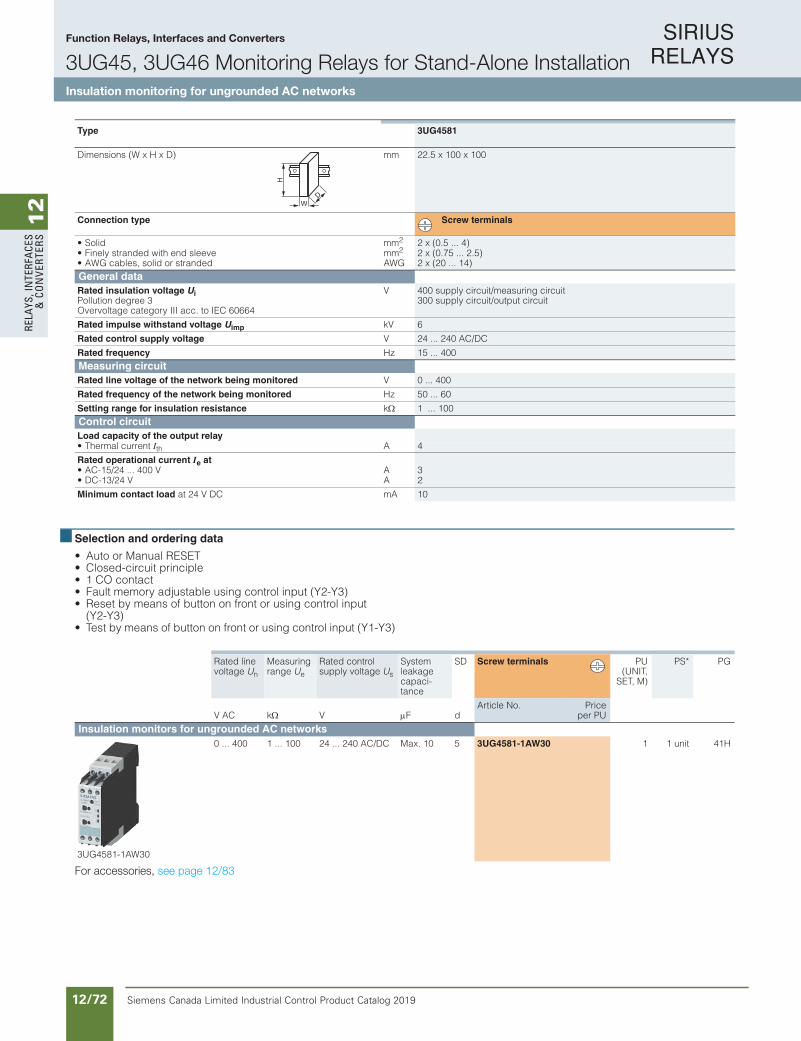
SIRIUS RELAYS
Siemens Canada Limited Industrial Control Product Catalog 201912/72
12
RELA
YS, I
NTE
RFA
CES
& C
ON
VERT
ERS
Function Relays, Interfaces and Converters
3UG45, 3UG46 Monitoring Relays for Stand-Alone InstallationInsulation monitoring for ungrounded AC networks
10/100 Siemens IC 10 · 2018* You can order this quantity or a multiple thereof.
Illustrations are approximate
RelaysSIRIUS 3UG45, 3UG46 Monitoring Relays for Stand-Alone InstallationInsulation Monitoring
For ungrounded AC networks
10
Selection and ordering data
• Auto or Manual RESET• Closed-circuit principle• 1 CO contact• Fault memory adjustable using control input (Y2-Y3)• Reset by means of button on front or using control input
(Y2-Y3)• Test by means of button on front or using control input (Y1-Y3)
For accessories, see page 10/111.
Type 3UG4581
Dimensions (W x H x D) mm 22.5 x 100 x 100
Connection type Screw terminals
• Solid mm2 2 x (0.5 ... 4)• Finely stranded with end sleeve mm2 2 x (0.75 ... 2.5)• AWG cables, solid or stranded AWG 2 x (20 ... 14)General data Rated insulation voltage Ui Pollution degree 3Overvoltage category III acc. to IEC 60664
V 400 supply circuit/measuring circuit300 supply circuit/output circuit
Rated impulse withstand voltage Uimp kV 6
Rated control supply voltage V 24 ... 240 AC/DC
Rated frequency Hz 15 ... 400 Measuring circuitRated line voltage of the network being monitored V 0 ... 400
Rated frequency of the network being monitored Hz 50 ... 60
Setting range for insulation resistance k 1 ... 100 Control circuitLoad capacity of the output relay• Thermal current Ith A 4
Rated operational current Ie at• AC-15/24 ... 400 V A 3• DC-13/24 V A 2
Minimum contact load at 24 V DC mA 10
W
H
D
Rated line voltage Un
Measuring range Ue
Rated control supply voltage Us
System leakage capaci-tance
SD Screw terminals PU(UNIT,
SET, M)
PS* PG
V AC k V F dArticle No. Price
per PU
Insulation monitors for ungrounded AC networks
3UG4581-1AW30
0 ... 400 1 ... 100 24 ... 240 AC/DC Max. 10 5 3UG4581-1AW30 1 1 unit 41H
IC10_10_09.fm Page 100 Thursday, February 22, 2018 8:50 PM
For accessories, see page 12/83
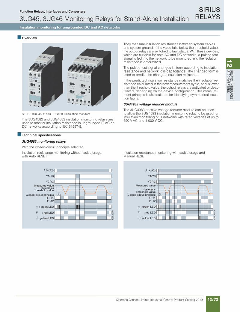
SIRIUS RELAYS
Siemens Canada Limited Industrial Control Product Catalog 2019 12/73
12
RELAYS, IN
TERFACES
& CO
NVERTERS
Function Relays, Interfaces and Converters
3UG45, 3UG46 Monitoring Relays for Stand-Alone InstallationInsulation monitoring for ungrounded DC and AC networks
10/101Siemens IC 10 · 2018
RelaysSIRIUS 3UG45, 3UG46 Monitoring Relays for Stand-Alone Installation
Insulation Monitoring
For ungrounded DC and AC networks
10
Overview
SIRIUS 3UG4582 and 3UG4583 insulation monitors
The 3UG4582 and 3UG4583 insulation monitoring relays are used to monitor insulation resistance in ungrounded IT AC or DC networks according to IEC 61557-8.
They measure insulation resistances between system cables and system ground. If the value falls below the threshold value, the output relays are switched to fault status. With these devices, which are suitable for both AC and DC networks, a pulsed test signal is fed into the network to be monitored and the isolation resistance is determined.
The pulsed test signal changes its form according to insulation resistance and network loss capacitance. The changed form is used to predict the changed insulation resistance.
If the predicted insulation resistance matches the insulation re-sistance calculated in the next measurement cycle, and is lower than the threshold value, the output relays are activated or deac-tivated, depending on the device configuration. This measure-ment principle is also suitable for identifying symmetrical insula-tion faults.
3UG4983 voltage reducer module
The 3UG4983 passive voltage reducer module can be used to allow the 3UG4583 insulation monitoring relay to be used for insulation monitoring of IT networks with rated voltages of up to 690 V AC and 1 000 V DC.
Technical specifications
3UG4582 monitoring relays
With the closed-circuit principle selected
Insulation resistance monitoring without fault storage, with Auto RESET
Insulation resistance monitoring with fault storage andManual RESET
F
Closed-circuit principle
Threshold valueHysteresis
Measured value
: yellow LED
: red LED
: green LED
IC01
_000
74
Y2-Y3
Y1-Y3
A1+/A2-
11-1411-12
st Closed-circuit principleThreshold value
HysteresisMeasured value
: yellow LED
: red LED
: green LED
Y2-Y3
Y1-Y3
A1+/A2-
11-1411-12
IC01
_000
75
st
F
IC10_10_09.fm Page 101 Thursday, February 22, 2018 8:50 PM

SIRIUS RELAYS
Siemens Canada Limited Industrial Control Product Catalog 201912/74
12
RELA
YS, I
NTE
RFA
CES
& C
ON
VERT
ERS
Function Relays, Interfaces and Converters
3UG45, 3UG46 Monitoring Relays for Stand-Alone InstallationInsulation monitoring for ungrounded DC and AC networks
10/102 Siemens IC 10 · 2018
RelaysSIRIUS 3UG45, 3UG46 Monitoring Relays for Stand-Alone InstallationInsulation Monitoring
For ungrounded DC and AC networks
10
3UG4583 monitoring relaysWith the closed-circuit principle selected
Insulation resistance monitoring without fault storage,with Auto RESET
Insulation resistance monitoring with fault storage and Manual RESET
closed
open
F
F
Final switch-offHysteresis
PrewarningHysteresis
Measured Value
Closed-circuitprinciple
Open-circuitprinciple
IC01
_000
83
LED
LED
LED
21-2421-24
11-1411-12
LED
LED
LED
21-2221-24
11-1411-12
Y2-Y3
Y1-Y3
A1+/A2-
st
closed
open
Final switch-offHysteresis
PrewarningHysteresis
Measured Value
Closed-circuitprinciple
Open-circuitprinciple
IC01
_000
84a
LED
LED
LED
21-2421-24
11-1411-12
LED
LED
LED
21-2221-24
11-1411-12
Y2-Y3
Y1-Y3
A1+/A2-
stst
F
F
Type 3UG4582 3UG4583mm)DxHxW( snoisnemiD 22.5 x 100 x 100 45 x 100 x 100
Connection type Screw terminals
mmdiloS• 2 2 x (0.5 ... 4)mmeveels dne htiw dednarts yleniF• 2 2 x (0.75 ... 2.5)
GWAdednarts ro dilos ,selbac GWA• 2 x (20 ... 14)General data Rated insulation voltage Ui Pollution degree 3Overvoltage category III acc. to IEC 60664
V 400 supply circuit/measuring circuit, 300 supply circuit/output circuit
400 supply circuit/measuring circuit300 supply circuit/output circuit,300 output circuit 1/output circuit 2
Rated impulse withstand voltage Uimp kV 6
Rated control supply voltage V AC/DC 24 ... 240
Rated frequency Hz 15 ... 400 Measuring circuitRated line voltage of the network being monitored V
V0 ... 250 AC,0 ... 300 DC
0 ... 300 AC, 0 ... 690 AC with 3UG49 830 ... 600 DC, 0 ... 1 000 DC with 3UG49 83
Rated frequency of the network being monitored Hz DC or 15 ... 400
Setting range for insulation resistance k 1 ... 100 1 ... 100,2 ... 200 for 2nd limit value (disconnectable)
Control circuitNumber of CO contacts for auxiliary contacts 1 2 or 1 + 1, adjustable
Load capacity of the output relay• Thermal current Ith A 4
Rated operational current Ie atAV004...42/51-CA• 3AV 42/31-CD• 2
Minimum contact load AmCDV42 ta 10
W
H
D
IC10_10_09.fm Page 102 Thursday, February 22, 2018 8:50 PM

SIRIUS RELAYS
Siemens Canada Limited Industrial Control Product Catalog 2019 12/75
12
RELAYS, IN
TERFACES
& CO
NVERTERS
Function Relays, Interfaces and Converters
3UG45, 3UG46 Monitoring Relays for Stand-Alone InstallationInsulation monitoring for ungrounded DC and AC networks
10/103Siemens IC 10 · 2018* You can order this quantity or a multiple thereof.Illustrations are approximate
RelaysSIRIUS 3UG45, 3UG46 Monitoring Relays for Stand-Alone Installation
Insulation Monitoring
For ungrounded DC and AC networks
10
Selection and ordering data
• Auto or Manual RESET• Rated control supply voltage Us 24 ... 240 V AC/DC• 3UG4582: Closed-circuit principle
3UG4583: Open-circuit or closed-circuit principle, adjustable• 1 or 2 CO contacts• Fault memory adjustable using control input (Y2-Y3)• Reset by means of button on front or using control input
(Y2-Y3)• Test by means of button on front or using control input (Y1-Y3)• 3UG4583: Non-volatile fault storage can be configured• 3UG4583: 2 separate limit values (e.g. for warning and
disconnection) or 2 CO contacts for one limit value (e.g. for a local alarm and signaling to the PLC via separate circuits) can be configured
Note:
With the 3UG4983-1A coupling unit, connection to networks with voltages of up to 690 V AC and 1 000 V DC is possible, see below.
Available
1) With 3UG4983-1A voltage reducer module suitable also for the insulation monitoring of IT networks of up to 690 V AC and 1 000 V DC.
For accessories, see page 10/111.
Rated line voltage Un
System leakage capaci-tance
Output relays
Measuring range Ue
Broken wire detection in the mea-suring range
SD Screw terminals PU(UNIT,
SET, M)
PS*
V F k dArticle No. Price
per PU
3UG4582 insulation monitors
3UG4582-1AW30
0 ... 250 AC,0 ... 300 DC
Max. 10 1 CO 1 ... 100 5 3UG4582-1AW30 1 1 unit
3UG4583 insulation monitors
3UG4583-1CW30
0 ... 400 AC, 0 ... 600 DC1)
Max. 20 2 CO or 1 CO +1 CO, adjustable
1 ... 100, 2 ... 200 for 2nd limit value, adjustable
Adjustable
5 3UG4583-1CW30 1 1 unit
Voltage reducer module for 3UG4583
3UG4983-1A
For extending the network voltage range to max. 690 V AC and 1 000 V DC
5 3UG4983-1A 1 1 unit
IC10_10_09.fm Page 103 Thursday, February 22, 2018 8:50 PM
For accessories, see page 12/83
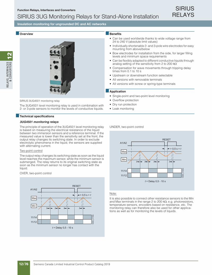
SIRIUS RELAYS
Siemens Canada Limited Industrial Control Product Catalog 201912/76
12
RELA
YS, I
NTE
RFA
CES
& C
ON
VERT
ERS
Function Relays, Interfaces and Converters
SIRIUS 3UG Monitoring Relays for Stand-Alone InstallationInsulation monitoring for ungrounded DC and AC networks
10/104 Siemens IC 10 · 2018
RelaysSIRIUS 3UG45, 3UG46 Monitoring Relays for Stand-Alone InstallationLevel Monitoring
Level monitoring relays
10
Overview
SIRIUS 3UG4501 monitoring relay
The 3UG4501 level monitoring relay is used in combination with 2- or 3-pole sensors to monitor the levels of conductive liquids.
Benefits
• Can be used worldwide thanks to wide voltage range from 24 to 240 V (absolute limit values)
• Individually shortenable 2- and 3-pole wire electrodes for easy mounting from above/below
• Bow electrodes for installation from the side, for larger filling levels and minimum space requirements
• Can be flexibly adapted to different conductive liquids through analog setting of the sensitivity from 2 to 200 k
• Compensation for wave movements through tripping delay times from 0.1 to 10 s
• Upstream or downstream function selectable• All versions with removable terminals• All versions with screw or spring-type terminals
Application
• Single-point and two-point level monitoring• Overflow protection• Dry run protection• Leak monitoring
Technical specifications
3UG4501 monitoring relays
The principle of operation of the 3UG4501 level monitoring relay is based on measuring the electrical resistance of the liquid between two immersion sensors and a reference terminal. If the measured value is lower than the sensitivity set at the front, the output relay changes its switching state. In order to exclude electrolytic phenomena in the liquid, the sensors are supplied with alternating current.
Two-point control
The output relay changes its switching state as soon as the liquid level reaches the maximum sensor, while the minimum sensor is submerged. The relay returns to its original switching state as soon as the minimum sensor no longer has contact with the liquid.
OVER, two-point control
UNDER, two-point control
Note:
It is also possible to connect other resistance sensors to the Min and Max terminals in the range 2 to 200 k, e.g. photoresistors, temperature sensors, encoders based on resistance, etc. The monitoring relay can therefore also be used for other applica-tions as well as for monitoring the levels of liquids.
11/14
A1/A2
t t
11/12
t t
NS
B0_
0179
9b
Max
Min
t = Delay 0,5 - 10 s
> 0,5 s + t
RESET
tt t t
t = Delay 0,5 - 10 s
> 0,5 s + t
RESET
NS
B0_
0180
0b
Max
Min
11/14
A1/A2
11/12
IC10_10_09.fm Page 104 Thursday, February 22, 2018 8:50 PM
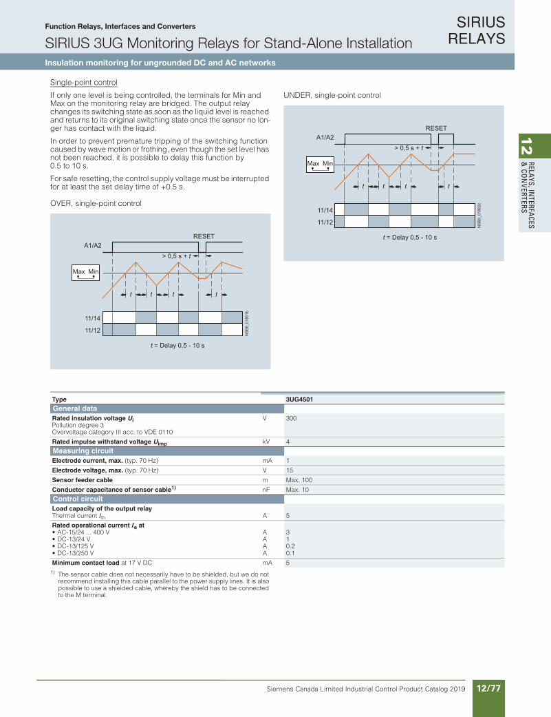
SIRIUS RELAYS
Siemens Canada Limited Industrial Control Product Catalog 2019 12/77
12
RELAYS, IN
TERFACES
& CO
NVERTERS
Function Relays, Interfaces and Converters
SIRIUS 3UG Monitoring Relays for Stand-Alone InstallationInsulation monitoring for ungrounded DC and AC networks
10/105Siemens IC 10 · 2018
RelaysSIRIUS 3UG45, 3UG46 Monitoring Relays for Stand-Alone Installation
Level Monitoring
Level monitoring relays
10
Single-point control
If only one level is being controlled, the terminals for Min and Max on the monitoring relay are bridged. The output relay changes its switching state as soon as the liquid level is reached and returns to its original switching state once the sensor no lon-ger has contact with the liquid.
In order to prevent premature tripping of the switching function caused by wave motion or frothing, even though the set level has not been reached, it is possible to delay this function by 0.5 to 10 s.
For safe resetting, the control supply voltage must be interrupted for at least the set delay time of +0.5 s.
OVER, single-point control
UNDER, single-point control
1) The sensor cable does not necessarily have to be shielded, but we do not recommend installing this cable parallel to the power supply lines. It is also possible to use a shielded cable, whereby the shield has to be connected to the M terminal.
> 0,5 s + t
11/14
A1/A2
t t
11/12
t t
Max Min
t = Delay 0,5 - 10 s
RESETN
SB
0_01
801b
11/14
A1/A2
t t
11/12
t t
Max Min
t = Delay 0,5 - 10 s
> 0,5 s + t
RESET
NS
B0_
0180
2c
Type 3UG4501General dataRated insulation voltage UiPollution degree 3 Overvoltage category III acc. to VDE 0110
V 300
Rated impulse withstand voltage Uimp kV 4Measuring circuitElectrode current, max. (typ. 70 Hz) mA 1
Electrode voltage, max. (typ. 70 Hz) V 15
Sensor feeder cable m Max. 100
Conductor capacitance of sensor cable1) nF Max. 10Control circuitLoad capacity of the output relayThermal current Ith A 5
Rated operational current Ie at• AC-15/24 ... 400 V A 3• DC-13/24 V A 1• DC-13/125 V A 0.2• DC-13/250 V A 0.1
Minimum contact load at 17 V DC mA 5
IC10_10_09.fm Page 105 Thursday, February 22, 2018 8:50 PM

SIRIUS RELAYS
Siemens Canada Limited Industrial Control Product Catalog 201912/78
12
RELA
YS, I
NTE
RFA
CES
& C
ON
VERT
ERS
Siemens / Industrial Controls Previous folio: IC10 11/49
For level monitoring sensors see page 12/79
Function Relays, Interfaces and Converters
3UG45, 3UG46 Monitoring Relays for Stand-Alone InstallationLevel monitoring: Level monitoring relays
Product Category: SMRL
10/106 Siemens IC 10 · 2018* You can order this quantity or a multiple thereof.
Illustrations are approximate
RelaysSIRIUS 3UG45, 3UG46 Monitoring Relays for Stand-Alone InstallationLevel Monitoring
Level monitoring relays
10
Selection and ordering data
• For level monitoring of electrically conductive liquids• Control principle: inlet or sequence control adjustable
per rotary switch • Single-point and two-point control possible• Analogically adjustable sensitivity (specific resistance of the
liquid)• Analogically adjustable tripping delay time• 1 yellow LED for displaying the relay state• 1 green LED for displaying the applied control supply voltage• 1 CO contact
PU (UNIT, SET, M) = 1PKG* = 1 UNITPG = 41H
1) The rated control supply voltage and the measuring circuit are not electrically separated.
For accessories, see page 10/111.
For level monitoring sensors, see page 10/107.
Sensitivity Tripping delay time Rated control supply voltage Us
SD Screw terminals SD Spring-type terminals
k sVAC/DC d
Article No. Priceper PU d
Article No. Priceper PU
2 ... 200 0.5 ... 10 241) 2 3UG4501-1AA30 2 3UG4501-2AA30
24 ... 240 2 3UG4501-1AW30 2 3UG4501-2AW30
IC10_10_09.fm Page 106 Thursday, February 22, 2018 8:50 PM
For accessories, see page 12/83
For level monitoring sensors, see page 12/79

SIRIUS RELAYS
Siemens Canada Limited Industrial Control Product Catalog 2019 12/79
12
RELAYS, IN
TERFACES
& CO
NVERTERS
Siemens / Industrial Controls Previous folio: IC10 11/50
Product Category: SMRL
10/107Siemens IC 10 · 2018* You can order this quantity or a multiple thereof.Illustrations are approximate
RelaysSIRIUS 3UG45, 3UG46 Monitoring Relays for Stand-Alone Installation
Level Monitoring
Level monitoring sensors
10
Technical specifications
Selection and ordering data
Type 3UG3207-3AThree-pole
3UG3207-2ATwo-pole
3UG3207-2BTwo-pole
3UG3207-1BSingle-pole
3UG3207-1CSingle-pole
Length mm 500 --
Insulation Teflon insulation (PTFE) Yes -- Yes
Installation Vertical Lateral
Screw-in gland width A/F 22
Thread inch R 3/8
Connecting cable mm2 3 x 0.5, 2 m long
Operating temperature °C 90
Operating pressure bar 10
Cable/electrode assignment
• Cable brown Center electrode Not assignable Gland
• Cable white Not assignable Electrode
• Cable green Not assignable -- Not assignable --
Version SD
d
Article No. Priceper PU
PU(UNIT,
SET, M)
PS*
Level monitoring sensors (essential accessory)The wire electrodes can be cut or bent to the required length before or after installation. The Teflon insulation must be removed over a length of approx. 5 mm.
3UG3207-3A
Three-pole wire electrodes, 500 mm long
For 2-point liquid level control in an insulating tank. One electrode each for the min. and max. value and a common reference electrode.
2 3UG3207-3A 1 1 unit
3UG3207-2A
Two-pole wire electrodes, 500 mm long
For alarm indication in the event of overflow or low level and for 2-point liquid level control, when the conductive tank is used as the reference electrode.
2 3UG3207-2A 1 1 unit
3UG3207-2B
Two-pole bow electrodes
Thanks to the small space requirements due to lateral fitting, ideal for use in small containers and pipes, as a leak monitor and level monitor or for warning of water entering an enclosure.
2 3UG3207-2B 1 1 unit
3UG3207-1B
Single-pole bow electrodes for lateral fitting
As a max. value electrode for lateral fitting or for alarm indicationin conductive tanks or pipes.
2 3UG3207-1B 1 1 unit
3UG3207-1C
Single-pole rod electrodes for lateral fitting
For high flow velocities or for intensively sparkling fluids.
2 3UG3207-1C 1 1 unit
IC10_10_09.fm Page 107 Thursday, February 22, 2018 8:50 PM
Function Relays, Interfaces and Converters
3UG45, 3UG46 Monitoring Relays for Stand-Alone InstallationLevel monitoring: Level monitoring sensors

SIRIUS RELAYS
Siemens Canada Limited Industrial Control Product Catalog 201912/80
12
RELA
YS, I
NTE
RFA
CES
& C
ON
VERT
ERS
Siemens / Industrial Controls Previous folio: IC10 11/51
Function Relays, Interfaces and Converters
3UG45, 3UG46 Monitoring Relays for Stand-Alone InstallationSpeed monitoring
10/108 Siemens IC 10 · 2018
RelaysSIRIUS 3UG45, 3UG46 Monitoring Relays for Stand-Alone Installation
Speed monitoring
10
Overview
SIRIUS 3UG4651 monitoring relay
The 3UG4651 monitoring relay is used in combination with a sensor to monitor motor drives for overspeed and/or under-speed.
Furthermore, the monitoring relay is ideal for all functions where a continuous pulse signal needs to be monitored (e.g. belt travel monitoring, completeness monitoring, passing monitoring, clock-time monitoring).
Benefits
• Can be used worldwide thanks to wide voltage range from 24 to 240 V (absolute limit values)
• Variably adjustable to overshoot, undershoot or range monitoring
• Freely configurable delay times and RESET response• Permanent display of actual value and fault type• Use of up to 10 sensors per rotation for extremely slowly
rotating motors• 2- or 3-wire sensors and sensors with a mechanical switching
output or semiconductor output can be connected• Auxiliary voltage for sensor integrated• All versions with removable terminals• All versions with screw or spring-type terminals
Application
• Slip or tear of a belt drive• Overload monitoring• Transport monitoring for completeness
Technical specifications
3UG4651 monitoring relay
The speed monitoring relay operates according to the principle of period duration measurement.
In the monitoring relay, the time between two successive rising edges of the pulse encoder is measured and compared to the minimum and/or maximum permissible period duration calcu-lated from the set limit values for the speed.
Thus, the period duration measurement recognizes any devia-tion in speed after just two pulses, even at very low speeds or in the case of extended pulse gaps.
By using up to ten pulse encoders evenly distributed around the circumference, it is possible to shorten the period duration, and in turn the response time. By taking into account the number of sensors in the monitoring relay, the speed continues to be indi-cated in rpm.
ON-delay time for motor start
To be able to start a motor drive, and depending on whether the open-circuit or closed-circuit principle is selected, the output re-lay switches to the GO state during the ON-delay time, even if the speed is still below the set value.
The ON-delay time is started by either switching on the auxiliary voltage or, if the auxiliary voltage is already applied, by actuating the respective NC contact (e.g. auxiliary contact).
Speed monitoring with Auto RESET (Memory = no)
If the device is set to Auto RESET, the output relay switches to the GO state, once the adjustable hysteresis threshold is reached in the range of 0.1 to 99.9 rpm and the flashing stops. Any overshoots or undershoots are therefore not stored.
Speed monitoring with Manual RESET (Memory = yes)
If Manual RESET is selected in the menu, the output relay re-mains in its current switching state and the current measured value and the symbol for overshooting/undershooting continue to flash, even when the speed returns to a permissible value. This stored fault status can be reset by simultaneously pressing the UP and DOWN keys for > 2 s, by connecting the RESET device terminal to 24 V DC or by switching the control supply voltage off and back on again.
IC10_10_09.fm Page 108 Thursday, February 22, 2018 8:50 PM
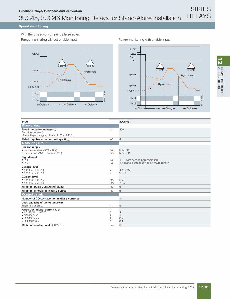
SIRIUS RELAYS
Siemens Canada Limited Industrial Control Product Catalog 2019 12/81
12
RELAYS, IN
TERFACES
& CO
NVERTERS
Siemens / Industrial Controls Previous folio: IC10 11/52
Function Relays, Interfaces and Converters
3UG45, 3UG46 Monitoring Relays for Stand-Alone InstallationSpeed monitoring
10/109Siemens IC 10 · 2018
RelaysSIRIUS 3UG45, 3UG46 Monitoring Relays for Stand-Alone Installation
Speed monitoring
10
With the closed-circuit principle selected
Range monitoring without enable input Range monitoring with enable input
11/14
A1/A2
11/12
NS
B0_
0180
3bonDelay Delay Delay
Hysteresis
Hysteresis
RPM = 0
rpm
rpm> RPM < RPM
NS
B0_
0180
4a
11/14
A1/A2
EN
11/12
onDelay Delay Delay
Hysteresis
Hysteresis
RPM = 0
rpm
> RPM < RPMrpm
Type 3UG4651General dataRated insulation voltage UiPollution degree 3 Overvoltage category III acc. to VDE 0110
V 300
Rated impulse withstand voltage Uimp kV 4Measuring circuitSensor supply• For 3-wire sensor (24 V/0 V) mA Max. 50• For 2-wire NAMUR sensor (8V2) mA Max. 8.2
Signal input• IN1 k 16, 3-wire sensor, pnp operation• IN2 k 1, floating contact, 2-wire NAMUR sensor
Voltage level• For level 1 at IN1 V 4.5 ... 30• For level 0 at IN1 V 0 ... 1
Current level• For level 1 at IN2 mA > 2.1• For level 0 at IN2 mA < 1.2
Minimum pulse duration of signal ms 5
Minimum interval between 2 pulses ms 5Control circuitNumber of CO contacts for auxiliary contacts 1
Load capacity of the output relayThermal current Ith A 5
Rated operational current Ie at• AC-15/24 ... 400 V A 3• DC-13/24 V A 1• DC-13/125 V A 0.2• DC-13/250 V A 0.1
Minimum contact load at 17 V DC mA 5
IC10_10_09.fm Page 109 Thursday, February 22, 2018 8:50 PM

SIRIUS RELAYS
Siemens Canada Limited Industrial Control Product Catalog 201912/82
12
RELA
YS, I
NTE
RFA
CES
& C
ON
VERT
ERS
Siemens / Industrial Controls Previous folio: IC10 11/53
Function Relays, Interfaces and Converters
3UG45, 3UG46 Monitoring Relays for Stand-Alone InstallationSpeed monitoring
10/110 Siemens IC 10 · 2018* You can order this quantity or a multiple thereof.
Illustrations are approximate
RelaysSIRIUS 3UG45, 3UG46 Monitoring Relays for Stand-Alone Installation
Speed monitoring
10
Selection and ordering data
• For speed monitoring in revolutions per minute (rpm)• Two- or three-wire sensor with mechanical or electronic
switching output can be connected• Two-wire NAMUR sensor can be connected• Sensor supply 24 V DC/50 mA integrated• Input frequency 0.1 to 2 200 pulses rpm
(0.0017 to 36.7 Hz)• With or without enable signal for the drive to be monitored• Digitally adjustable, with illuminated LCD• Overshoot, undershoot or range monitoring adjustable• Number of pulses per revolution can be adjusted• Upper and lower threshold value can be adjusted separately• Auto, manual or remote RESET options after tripping• Permanent display of actual value and tripping state• 1 CO contact
PU (UNIT, SET, M) = 1PKG* = 1 UNITPG = 41H
1) The rated control supply voltage and the measuring circuit are not electrically separated.
For accessories, see page 10/111.
Measuring range
Hysteresis ON-delay time
Tripping delay time
Pulses per revo-lution
Rated control supply voltage Us
SD Screw terminals SD Spring-type terminals
AC/DC
rpm rpm s s V dArticle No. Price
per PU dArticle No. Price
per PU
0.1 ... 2 200 OFF0.1 ... 99.9
0 ... 900 0.1 ... 99.9 1 ... 10 241) 2 3UG4651-1AA30 2 3UG4651-2AA30
24 ... 240 2 3UG4651-1AW30 2 3UG4651-2AW30
IC10_10_09.fm Page 110 Thursday, February 22, 2018 8:50 PM
For accessories, see page 12/83

SIRIUS RELAYS
Siemens Canada Limited Industrial Control Product Catalog 2019 12/83
12
RELAYS, IN
TERFACES
& CO
NVERTERS
Siemens / Industrial Controls Previous folio:IC10 11/54
Product Category: SMRL
10/111Siemens IC 10 · 2018* You can order this quantity or a multiple thereof.Illustrations are approximate
RelaysSIRIUS 3UG45, 3UG46 Monitoring Relays for Stand-Alone Installation
Accessories
10
Selection and ordering data
Note:
For products for mechanical bearing monitoring, e.g. condition monitoring systems, see www.siemens.com/siplus-cms.
Use Version SD
d
Article No. Priceper PU
PU(UNIT,
SET,M)
PS*
Blank labels
3RT1900-1SB20
For 3UG4 Unit labeling plates For SIRIUS devices
20 mm x 7 mm, pastel turquoise 20 3RT1900-1SB20 100 340 units
For 3UG4 Adhesive labels for SIRIUS devices
• 19 mm x 6 mm, pastel turquoise 15 3RT1900-1SB60 100 3 060 units
• 19 mm x 6 mm, zinc yellow 15 3RT1900-1SD60 100 3 060 units
Push-in lugs and covers
3RP1903
For 3UG4 Push-in lugsFor screw fixing,2 units are required for each device
5 3RP1903 1 10 units
3RP1902
For 3UG4 Sealable coversFor securing against unauthorized adjustment of setting knobs
5 3RP1902 1 5 units
For 3UG45 Sealing foilFor securing against unauthorized adjustment of setting knobs
3TK2820-0AA00 1 1 unit
Covers for insulation monitoring relaysSealable, transparent covers
3UG4981-0C
For 3UG4581 and 3UG4582
5 3UG4981-0C 1 1 unit
3UG4983-0C
For 3UG4583 5 3UG4983-0C 1 1 unit
Tools for opening spring-type terminals
3RA2908-1A
For auxiliary cir-cuit connections
Screwdrivers For all SIRIUS devices with spring-type terminals; 3.0 mm x 0.5 mm; length approx. 200 mm, titanium gray/black, partially insulated
Spring-type terminals
2 3RA2908-1A 1 1 unit
NSB
0_01
429b
IC10_10_09.fm Page 111 Thursday, February 22, 2018 8:50 PM
Function Relays, Interfaces and Converters
3UG45, 3UG46 Monitoring Relays for Stand-Alone InstallationAccessories

SIRIUS RELAYS
Siemens Canada Limited Industrial Control Product Catalog 201912/84
12
RELA
YS, I
NTE
RFA
CES
& C
ON
VERT
ERS
Siemens / Industrial Controls Previous folio: IC10 11/55
Function Relays, Interfaces and Converters
3UG48 Monitoring Relays for Stand-Alone Installation for IO-LinkGeneral data
10/112 Siemens IC 10 · 2018
RelaysSIRIUS 3UG48 Monitoring Relays for Stand-Alone Installation for IO-Link
General data
10
Overview
SIRIUS 3UG48 monitoring relays
The SIRIUS 3UG4 monitoring relays for electronic and mechan-ical variables monitor all important characteristics that allow conclusions to be drawn about the functionality of a plant. Both sudden disturbances and gradual changes, which may indicate the need for maintenance, are detected.
Thanks to their relay outputs, the monitoring relays permit direct disconnection of the affected system components and alerting, e.g. by the triggering of a warning light. Thanks to adjustable de-lay times the 3UG4 monitoring relays can respond very flexibly to brief faults such as voltage dips or load changes and can thus avoid unnecessary alarms and disconnections and increase system availability.
3UG48 monitoring relays for IO-LinkThe SIRIUS 3UG48 monitoring relays for IO-Link also offer many other options based upon the monitoring functions of the tried-and-tested SIRIUS 3UG4 monitoring relays:• Measured value transmission to a controller, including resolu-
tion and unit, may be parameterizable as to which value is cyclically transmitted
• Transmission of alarm flags to a controller• Full diagnosis capability by inquiry as to the cause of the fault
in the diagnosis data record• Remote parameterization is also possible, in addition to or
instead of local parameterization• Rapid parameterization of the same devices by duplication of
the parameterization in the controller• Parameter transmission through uploading to a controller by
IO-Link call or by parameter server (if IO-Link master from IO-Link Specification V1.1 and higher is used)
• Consistent central data storage in the event of parameter change locally or via a controller
• Automatic reparameterizing when devices are exchanged• Blocking of local parameterization via IO-Link possible• Faults are saved in parameterizable and non-volatile fashion
to prevent an automatic start up after voltage failure and to make sure diagnostics data is not lost
• Integration into the automation level provides the option of parameterizing the monitoring relays at any time via a display unit, or displaying the measured values in a control room or locally at the machine/control cabinet
Even without communication via IO-Link the devices continue to function fully autonomously:• Parameterization can take place locally at the device,
independently of a controller.• In the event of failure or before the controller becomes avail-
able the monitoring relays work as long as the control supply voltage (24 V DC) is present.
• If the monitoring relays are operated without the controller,the 3UG48 monitoring relays have, thanks to the integrated SIO mode, an additional semiconductor output, which switches when the adjustable warning threshold is exceeded.
Thanks to the combination of autonomous monitoring relay func-tion and integrated IO-Link communication, redundant sensors and/or analog signal converters – which previously took over the transmission of measured values to a controller, leading to con-siderable extra cost and wiring outlay – are no longer needed.
Because the output relays are still present, the monitoring relays increase the functional reliability of the system, since only the controller can fulfill the control tasks if the current measured values are available, whereas the output relays can also be used for the disconnection of the system if limit values that cannot be reached during operation are exceeded.
The individual 3UG48 monitoring relays for IO-Link offer the following functions in different combinations:• Phase sequence• Phase failure, neutral conductor failure• Phase asymmetry• Undershooting and/or overshooting of limit values for voltage• Undershooting and/or overshooting of limit values for current• Undershooting and/or overshooting of power factor limit
values• Monitoring of the active current or the apparent current• Monitoring of the residual current• Undershooting and/or overshooting of limit values for speed
Note:
For more information on the IO-Link bus system, see page 2/98 onwards.
Notes on security
In order to protect plants, systems, machines and networks against cyber threats, it is necessary to implement – and contin-uously maintain – a holistic, state-of-the-art industrial security concept. Siemens products and solutions represent only one component of such a concept.
For more information on Industrial Security, see www.siemens.com/industrialsecurity.
More information
Homepage, see www.siemens.com/relays
Industry Mall, see www.siemens.com/product?3UG48
For the conversion tool, e.g. from 3UG3 to 3UG4, seewww.siemens.com/sirius/conversion-tool
IC10_10_10.fm Page 112 Thursday, February 22, 2018 9:30 PM
For more information on the IO-Link bus system, click here.
For more information on Industrial Security, see www.siemens.com/industrialsecurity.
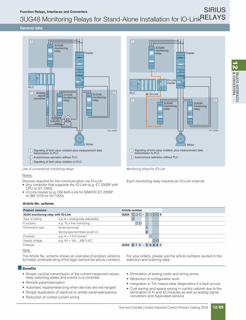
SIRIUS RELAYS
Siemens Canada Limited Industrial Control Product Catalog 2019 12/85
12
RELAYS, IN
TERFACES
& CO
NVERTERS
Siemens / Industrial Controls Previous folio: IC10 11/56
Function Relays, Interfaces and Converters
3UG48 Monitoring Relays for Stand-Alone Installation for IO-LinkGeneral data
10/113Siemens IC 10 · 2018
RelaysSIRIUS 3UG48 Monitoring Relays for Stand-Alone Installation for IO-Link
General data
10
kniL-OI rof syaler gnirotinoMsyaler gnirotinom lanoitnevnoc fo esU
Notes:
Devices required for the communication via IO-Link:• Any controller that supports the IO-Link (e.g. ET 200SP with
CPU or S7-1200).• IO-Link master (e.g. CM 4xIO-Link for SIMATIC ET 200SP
or SM 1278 for S7-1200).
Each monitoring relay requires an IO-Link channel.
Article No. scheme
Note:
The Article No. scheme shows an overview of product versions for better understanding of the logic behind the article numbers.
For your orders, please use the article numbers quoted in the selection and ordering data.
Benefits• Simple cyclical transmission of the current measured values,
relay switching states and events to a controller• Remote parameterization• Automatic reparameterizing when devices are exchanged• Simple duplication of identical or similar parameterizations• Reduction of control current wiring
• Elimination of testing costs and wiring errors• Reduction of configuration work• Integration in TIA means clear diagnostics if a fault occurs• Cost saving and space saving in control cabinet due to the
elimination of AI and IO modules as well as analog signal converters and duplicated sensors
3
1 2
Feeder
PLC
Motor
3UG46monitoring relay
3UG46monitoring relay
3UG46monitoring relay
Analog signal
converter
Current transfor-
mers
Autonomous operation without PLC
Signaling of limit value violation plus measurement data transmission to PLC
Signaling of limit value violation to PLC
1
23
IC01_00003
2
1
1
PLC
IO-Link master
3UG48monitoring relay
3UG48monitoring relay
3UG48monitoring relay Feeder
Autonomous operation without PLC
Signaling of limit value violation plus measurement data transmission to PLC
2
Motor
1
IC01_00004
IO-Link
Product versions Article number3UG4 monitoring relay with IO-Link 3UG4 @ @ @ Ð @ @ @ @ 0Type of setting e.g. 8 = analogically adjustable @Functions e.g. 15 = line monitoring @ @Connection type Screw terminals 1
Spring-type terminals (push-in) 2Contacts e.g. A = 1 CO contact @Supply voltage e.g. A4 = 160 ... 690 V AC @ @Example 3UG4 8 1 5 Ð 1 A A 4 0
IC10_10_10.fm Page 113 Thursday, February 22, 2018 9:30 PM
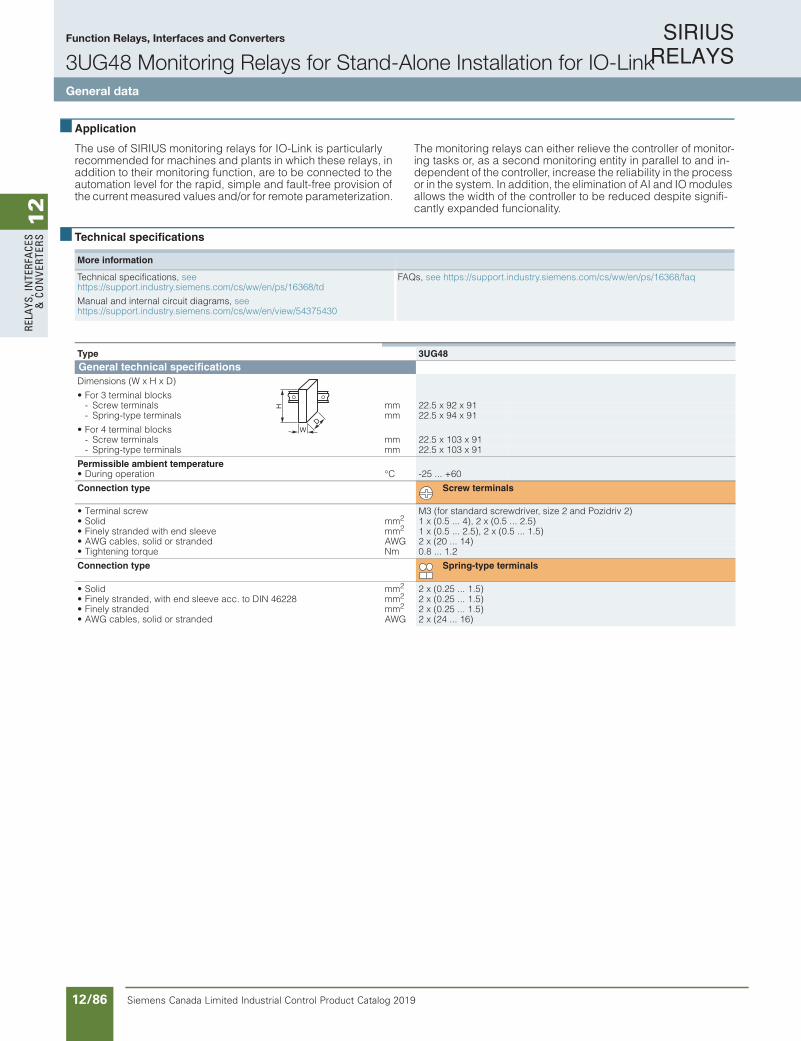
SIRIUS RELAYS
Siemens Canada Limited Industrial Control Product Catalog 201912/86
12
RELA
YS, I
NTE
RFA
CES
& C
ON
VERT
ERS
Function Relays, Interfaces and Converters
3UG48 Monitoring Relays for Stand-Alone Installation for IO-LinkGeneral data
10/114 Siemens IC 10 · 2018
RelaysSIRIUS 3UG48 Monitoring Relays for Stand-Alone Installation for IO-Link
General data
10
Application
The use of SIRIUS monitoring relays for IO-Link is particularly recommended for machines and plants in which these relays, in addition to their monitoring function, are to be connected to the automation level for the rapid, simple and fault-free provision of the current measured values and/or for remote parameterization.
The monitoring relays can either relieve the controller of monitor-ing tasks or, as a second monitoring entity in parallel to and in-dependent of the controller, increase the reliability in the process or in the system. In addition, the elimination of AI and IO modules allows the width of the controller to be reduced despite signifi-cantly expanded funcionality.
Technical specifications
More information
Technical specifications, see https://support.industry.siemens.com/cs/ww/en/ps/16368/td
Manual and internal circuit diagrams, seehttps://support.industry.siemens.com/cs/ww/en/view/54375430
FAQs, see https://support.industry.siemens.com/cs/ww/en/ps/16368/faq
Type 3UG48General technical specificationsDimensions (W x H x D)
• For 3 terminal blocks- Screw terminals mm 22.5 x 92 x 91- Spring-type terminals mm 22.5 x 94 x 91
• For 4 terminal blocks- Screw terminals mm 22.5 x 103 x 91- Spring-type terminals mm 22.5 x 103 x 91
Permissible ambient temperature• During operation °C -25 ... +60
Connection type Screw terminals
• Terminal screw M3 (for standard screwdriver, size 2 and Pozidriv 2)• Solid mm2 1 x (0.5 ... 4), 2 x (0.5 ... 2.5)• Finely stranded with end sleeve mm2 1 x (0.5 ... 2.5), 2 x (0.5 ... 1.5)• AWG cables, solid or stranded AWG 2 x (20 ... 14)• Tightening torque Nm 0.8 ... 1.2
Connection type Spring-type terminals
• Solid mm2 2 x (0.25 ... 1.5)• Finely stranded, with end sleeve acc. to DIN 46228 mm2 2 x (0.25 ... 1.5)• Finely stranded mm2 2 x (0.25 ... 1.5)• AWG cables, solid or stranded AWG 2 x (24 ... 16)
W
H
D
IC10_10_10.fm Page 114 Thursday, February 22, 2018 9:30 PM
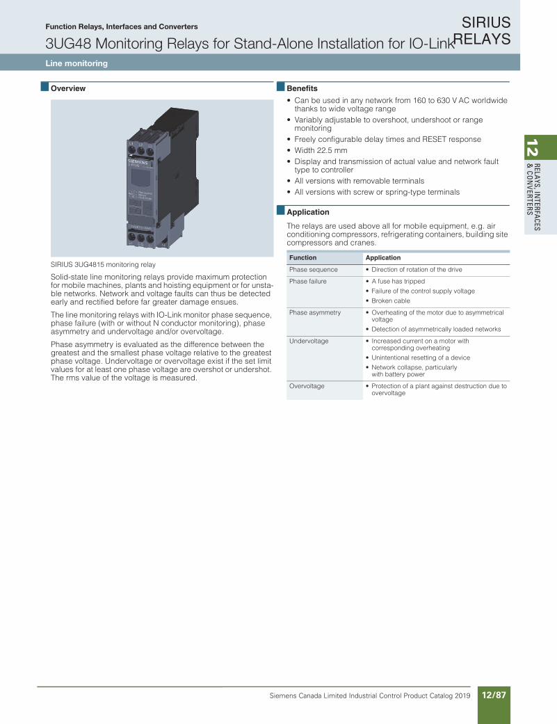
SIRIUS RELAYS
Siemens Canada Limited Industrial Control Product Catalog 2019 12/87
12
RELAYS, IN
TERFACES
& CO
NVERTERS
10/115Siemens IC 10 · 2018
RelaysSIRIUS 3UG48 Monitoring Relays for Stand-Alone Installation for IO-Link
Line monitoring
10
Overview
SIRIUS 3UG4815 monitoring relay
Solid-state line monitoring relays provide maximum protection for mobile machines, plants and hoisting equipment or for unsta-ble networks. Network and voltage faults can thus be detected early and rectified before far greater damage ensues.
The line monitoring relays with IO-Link monitor phase sequence, phase failure (with or without N conductor monitoring), phase asymmetry and undervoltage and/or overvoltage.
Phase asymmetry is evaluated as the difference between the greatest and the smallest phase voltage relative to the greatest phase voltage. Undervoltage or overvoltage exist if the set limit values for at least one phase voltage are overshot or undershot. The rms value of the voltage is measured.
Benefits
• Can be used in any network from 160 to 630 V AC worldwide thanks to wide voltage range
• Variably adjustable to overshoot, undershoot or range monitoring
• Freely configurable delay times and RESET response• Width 22.5 mm• Display and transmission of actual value and network fault
type to controller• All versions with removable terminals• All versions with screw or spring-type terminals
Application
The relays are used above all for mobile equipment, e.g. air conditioning compressors, refrigerating containers, building site compressors and cranes.
Function Application
Phase sequence • Direction of rotation of the drive
Phase failure • A fuse has tripped
• Failure of the control supply voltage
• Broken cable
Phase asymmetry • Overheating of the motor due to asymmetrical voltage
• Detection of asymmetrically loaded networks
Undervoltage • Increased current on a motor with corresponding overheating
• Unintentional resetting of a device
• Network collapse, particularlywith battery power
Overvoltage • Protection of a plant against destruction due to overvoltage
IC10_10_10.fm Page 115 Thursday, February 22, 2018 9:30 PM
Function Relays, Interfaces and Converters
3UG48 Monitoring Relays for Stand-Alone Installation for IO-LinkLine monitoring

SIRIUS RELAYS
Siemens Canada Limited Industrial Control Product Catalog 201912/88
12
RELA
YS, I
NTE
RFA
CES
& C
ON
VERT
ERS
Function Relays, Interfaces and Converters
3UG48 Monitoring Relays for Stand-Alone Installation for IO-LinkLine monitoring
10/116 Siemens IC 10 · 2018
RelaysSIRIUS 3UG48 Monitoring Relays for Stand-Alone Installation for IO-Link
Line monitoring
10
Technical specifications
3UG4815/3UG4816 monitoring relaysThe 3UG4815 and 3UG4816 line monitoring relays have a wide voltage range input and are supplied with power through IO-Link or from an external 24 V DC source.
The device is equipped with a display and is parameterized us-ing three buttons. The 3UG4815 monitoring relay monitors three-phase networks with regard to phase sequence, phase failure, phase asymmetry, undervoltage and overvoltage. The 3UG4816 monitoring relay monitors the neutral conductor as well. The hys-teresis is adjustable from 1 to 20 V.
The device has two separately adjustable delay times for over-voltage and undervoltage and for line stabilization. If the direc-tion of rotation is incorrect or a phase fails, the device switches off immediately. Thanks to a special measuring method, a phase failure is reliably detected in spite of the wide voltage range from and potentially high feedback through the load.
The 3UG4815 and 3UG4816 monitoring relays can be operated on the basis of either the open-circuit or closed-circuit principle and with Manual or Auto RESET.
If Manual RESET is selected in the menu (Memory = Yes), the switching relay remains in its current switching state and the cur-rent measured value and the symbol for undershooting and overshooting continues to flash, even when the measured vari-able reaches a permissible value again. This stored fault status can be reset by simultaneously pressing the UP and DOWN keys for 2.5 s.
With Manual RESET through IO-Link it is possible in addition to set whether error signals are to be deleted when the control sup-ply voltage is switched off and on (as remote RESET) or whether the signals are to be permanently saved even in a voltage failure, with confirmation possible only through local RESET or viaIO-Link.
With the closed-circuit principle selected
Wrong phase sequence
Phase failure
Undervoltage
Overvoltage
IC01
_000
05L3-L2-L111/1411/12
11/1411/12
L1-L2-L3L1-L2-L3-N
L2-L3L1-L2-L3
L1-L2-L3L1-L2-L3-N
IC01
_000
06IC
01_0
0007
< U
L+/L-
Q offQ on
11/1211/14
Ux-y
DelaystDelay
Hysteresis
> U
L+/L-
Q offQ on
11/1211/14
Ux-y
DelaystDelay
Hysteresis
IC01
_000
08
Type 3UG4815, 3UG4816General technical specificationsRated insulation voltage UiPollution degree 2Overvoltage category III acc. to VDE 0110
V 690
Rated impulse withstand voltage Uimp kV 6Control circuitLoad capacity of the output relay• Thermal current Ith A 5
Rated operational current Ie atAV004...42/51-CA• 3
• DC-13 atAV 42- 1AV 521- 0.2AV052- 0.1
Minimum contact load AmCDV71 ta 5
Electrical endurance AC-15 Million operating cycles
0.1
Mechanical endurance Million operating cycles
10
IC10_10_10.fm Page 116 Thursday, February 22, 2018 9:30 PM
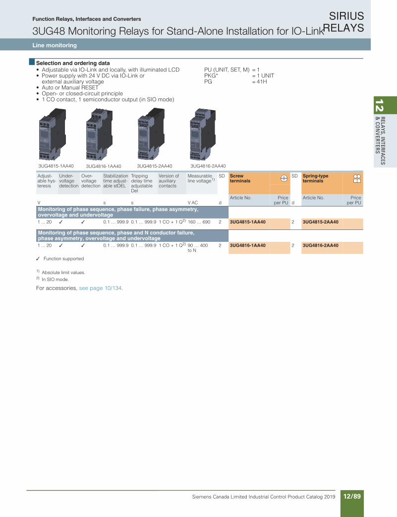
SIRIUS RELAYS
Siemens Canada Limited Industrial Control Product Catalog 2019 12/89
12
RELAYS, IN
TERFACES
& CO
NVERTERS
Function Relays, Interfaces and Converters
3UG48 Monitoring Relays for Stand-Alone Installation for IO-LinkLine monitoring
10/117Siemens IC 10 · 2018* You can order this quantity or a multiple thereof.Illustrations are approximate
RelaysSIRIUS 3UG48 Monitoring Relays for Stand-Alone Installation for IO-Link
Line monitoring
10
Selection and ordering data • Adjustable via IO-Link and locally, with illuminated LCD• Power supply with 24 V DC via IO-Link or
external auxiliary voltage• Auto or Manual RESET• Open- or closed-circuit principle• 1 CO contact, 1 semiconductor output (in SIO mode)
PU (UNIT, SET, M) = 1PKG* = 1 UNITPG = 41H
Function supported
1) Absolute limit values.2) In SIO mode.
For accessories, see page 10/134.
Adjust-able hys-teresis
Under-voltage detection
Over-voltage detection
Stabilizationtime adjust-able stDEL
Tripping delay time adjustable Del
Version of auxiliary contacts
Measurable line voltage1)
SD Screw terminals
SD Spring-type terminals
V s s V AC dArticle No. Price
per PU dArticle No. Price
per PUMonitoring of phase sequence, phase failure, phase asymmetry, overvoltage and undervoltage 1 ... 20 0.1 … 999.9 0.1 … 999.9 1 CO + 1 Q2) 160 … 690 2 3UG4815-1AA40 2 3UG4815-2AA40
Monitoring of phase sequence, phase and N conductor failure, phase asymmetry, overvoltage and undervoltage 1 ... 20 0.1 … 999.9 0.1 … 999.9 1 CO + 1 Q2) 90 … 400
to N2 3UG4816-1AA40 2 3UG4816-2AA40
3UG4815-1AA40 3UG4816-1AA40 3UG4815-2AA40 3UG4816-2AA40
IC10_10_10.fm Page 117 Thursday, February 22, 2018 9:30 PM

SIRIUS RELAYS
Siemens Canada Limited Industrial Control Product Catalog 201912/90
12
RELA
YS, I
NTE
RFA
CES
& C
ON
VERT
ERS
10/118 Siemens IC 10 · 2018
RelaysSIRIUS 3UG48 Monitoring Relays for Stand-Alone Installation for IO-Link
Voltage monitoring
10
Overview
SIRIUS 3UG4832 monitoring relays
The relays monitor single-phase AC voltages (rms value) and DC voltages against the set limit value for overshoot and undershoot.
Benefits
• Variably adjustable to overshoot, undershoot or range monitoring
• Freely configurable delay times and RESET response• Width 22.5 mm• Display and transmission of actual value and status messages
to controller• All versions with removable terminals• All versions with screw or spring-type terminals
Application
• Protection of a plant against destruction due to overvoltage• Switch-on of a plant at a defined voltage and higher• Protection from undervoltage due to overloaded control
supply voltages, particularly with battery power
Technical specifications
3UG4832 monitoring relays
The 3UG4832 voltage monitoring relays are supplied with power through IO-Link or with an external auxiliary voltage of 24 V DC and perform overshoot, undershoot or range monitoring of the voltage depending on parameterization. The devices are equipped with a display and are parameterized by means of three buttons or through IO-Link.
The measuring range extends from 10 to 600 V AC/DC. The limit values for overshoot or undershoot can be freely configured within this range. If one of these limit values is reached, the out-put relay responds according to the set principle of operation as soon as the delay time has elapsed. This tripping delay time UDel/UDel can be set from 0 to 999.9 s, as can the ON-delay time onDel. The hysteresis is adjustable from 0.1 to 300 V.
The device can be operated on the basis of either the open-cir-cuit or closed-circuit principle and with Manual or Auto RESET. One output changeover contact is available as a signaling con-tact, and a semiconductor output is available in addition in SIO mode.
If Manual RESET is selected in the menu (Memory = Yes), the switching relay remains in its current switching state and the cur-rent measured value and the symbol for undershooting and overshooting continues to flash, even when the measured vari-able reaches a permissible value again. This stored fault status can be reset by simultaneously pressing the UP and DOWN keys for 2.5 s.
With Manual RESET through IO-Link it is possible in addition to set whether error signals are to be deleted when the control sup-ply voltage is switched off and on (as remote RESET) or whether the signals are to be permanently saved even in a voltage failure, with confirmation possible only through local RESET or viaIO-Link.
With the closed-circuit principle selected
Overvoltage
Undervoltage
IC01
_000
11
< U
L+/L-
Q offQ on
11/1211/14
= 0, !
Hysteresis
DelayIC
01_0
0012
< U
L+/L-
Q offQ on
11/1211/14
, !Hysteresis
Delay
IC10_10_10.fm Page 118 Thursday, February 22, 2018 9:30 PM
Function Relays, Interfaces and Converters
3UG48 Monitoring Relays for Stand-Alone Installation for IO-LinkVoltage monitoring
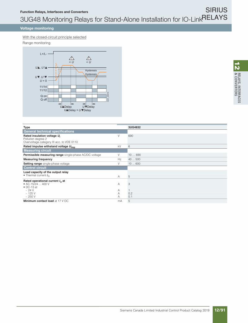
SIRIUS RELAYS
Siemens Canada Limited Industrial Control Product Catalog 2019 12/91
12
RELAYS, IN
TERFACES
& CO
NVERTERS
Function Relays, Interfaces and Converters
3UG48 Monitoring Relays for Stand-Alone Installation for IO-LinkVoltage monitoring
10/119Siemens IC 10 · 2018
RelaysSIRIUS 3UG48 Monitoring Relays for Stand-Alone Installation for IO-Link
Voltage monitoring
10
With the closed-circuit principle selected
Range monitoring
IC01
_000
13
L+/L-
U = 0
Q offQ on
11/1211/14
, !
, !
< U< U
Hysteresis
Delay = Delay
Hysteresis
Delay Delay
Type 3UG4832General technical specificationsRated insulation voltage UiPollution degree 2Overvoltage category III acc. to VDE 0110
V 690
Rated impulse withstand voltage Uimp kV 6Measuring circuitPermissible measuring range single-phase AC/DC voltage V 10 … 690
Measuring frequency Hz 40 ... 500
Setting range single-phase voltage V 10 ... 600Control circuitLoad capacity of the output relay• Thermal current Ith A 5
Rated operational current Ie at• AC-15/24 ... 400 V A 3• DC-13 at
- 24 V A 1- 125 V A 0.2- 250 V A 0.1
Minimum contact load at 17 V DC mA 5
IC10_10_10.fm Page 119 Thursday, February 22, 2018 9:30 PM
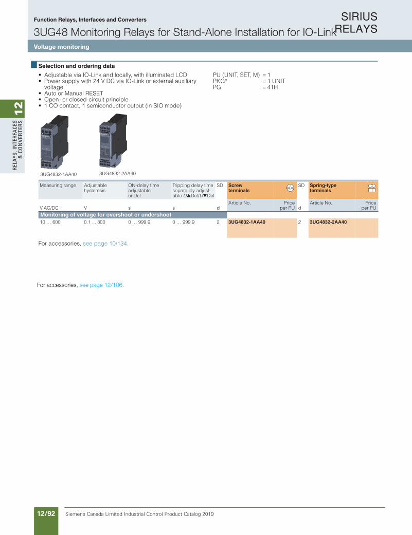
SIRIUS RELAYS
Siemens Canada Limited Industrial Control Product Catalog 201912/92
12
RELA
YS, I
NTE
RFA
CES
& C
ON
VERT
ERS
Function Relays, Interfaces and Converters
3UG48 Monitoring Relays for Stand-Alone Installation for IO-LinkVoltage monitoring
10/120 Siemens IC 10 · 2018* You can order this quantity or a multiple thereof.
Illustrations are approximate
RelaysSIRIUS 3UG48 Monitoring Relays for Stand-Alone Installation for IO-Link
Voltage monitoring
10
Selection and ordering data
• Adjustable via IO-Link and locally, with illuminated LCD• Power supply with 24 V DC via IO-Link or external auxiliary
voltage• Auto or Manual RESET• Open- or closed-circuit principle• 1 CO contact, 1 semiconductor output (in SIO mode)
PU (UNIT, SET, M) = 1PKG* = 1 UNITPG = 41H
For accessories, see page 10/134.
Measuring range Adjustable hysteresis
ON-delay time adjustable onDel
Tripping delay time separately adjust-able UDel/UDel
SD Screw terminals
SD Spring-type terminals
V AC/DC V s s dArticle No. Price
per PU dArticle No. Price
per PUMonitoring of voltage for overshoot or undershoot10 … 600 0.1 ... 300 0 … 999.9 0 … 999.9 2 3UG4832-1AA40 2 3UG4832-2AA40
3UG4832-1AA40 3UG4832-2AA40
IC10_10_10.fm Page 120 Thursday, February 22, 2018 9:30 PM
For accessories, see page 12/106.
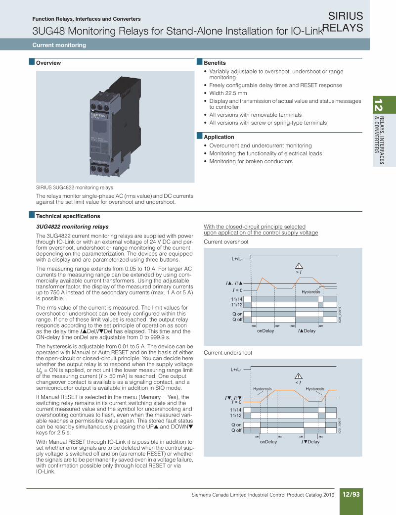
SIRIUS RELAYS
Siemens Canada Limited Industrial Control Product Catalog 2019 12/93
12
RELAYS, IN
TERFACES
& CO
NVERTERS
10/121Siemens IC 10 · 2018
RelaysSIRIUS 3UG48 Monitoring Relays for Stand-Alone Installation for IO-Link
Current monitoring
10
Overview
SIRIUS 3UG4822 monitoring relays
The relays monitor single-phase AC (rms value) and DC currents against the set limit value for overshoot and undershoot.
Benefits
• Variably adjustable to overshoot, undershoot or range monitoring
• Freely configurable delay times and RESET response• Width 22.5 mm• Display and transmission of actual value and status messages
to controller• All versions with removable terminals• All versions with screw or spring-type terminals
Application
• Overcurrent and undercurrent monitoring• Monitoring the functionality of electrical loads• Monitoring for broken conductors
Technical specifications
3UG4822 monitoring relays
The 3UG4822 current monitoring relays are supplied with power through IO-Link or with an external voltage of 24 V DC and per-form overshoot, undershoot or range monitoring of the current depending on the parameterization. The devices are equipped with a display and are parameterized using three buttons.
The measuring range extends from 0.05 to 10 A. For larger AC currents the measuring range can be extended by using com-mercially available current transformers. Using the adjustable transformer factor, the display of the measured primary currents up to 750 A instead of the secondary currents (max. 1 A or 5 A) is possible.
The rms value of the current is measured. The limit values for overshoot or undershoot can be freely configured within this range. If one of these limit values is reached, the output relayresponds according to the set principle of operation as soon as the delay time IDel/IDel has elapsed. This time and the ON-delay time onDel are adjustable from 0 to 999.9 s.
The hysteresis is adjustable from 0.01 to 5 A. The device can be operated with Manual or Auto RESET and on the basis of either the open-circuit or closed-circuit principle. You can decide here whether the output relay is to respond when the supply voltage Us = ON is applied, or not until the lower measuring range limit of the measuring current (I > 50 mA) is reached. One output changeover contact is available as a signaling contact, and a semiconductor output is available in addition in SIO mode.
If Manual RESET is selected in the menu (Memory = Yes), the switching relay remains in its current switching state and the current measured value and the symbol for undershooting and overshooting continues to flash, even when the measured vari-able reaches a permissible value again. This stored fault status can be reset by simultaneously pressing the UP and DOWN keys for 2.5 s.
With Manual RESET through IO-Link it is possible in addition to set whether error signals are to be deleted when the control sup-ply voltage is switched off and on (as remote RESET) or whether the signals are to be permanently saved even in a voltage failure, with confirmation possible only through local RESET or via IO-Link.
With the closed-circuit principle selectedupon application of the control supply voltage
Current overshoot
Current undershoot
L+/L-
= 0
Q offQ on
11/1211/14
>
, !
Delay
Hysteresis
onDelay
IC01
_000
16IC
01_0
0017
L+/L-
= 0
Q offQ on
11/1211/14
<
, !
onDelay
HysteresisHysteresis
Delay
IC10_10_10.fm Page 121 Thursday, February 22, 2018 9:30 PM
Function Relays, Interfaces and Converters
3UG48 Monitoring Relays for Stand-Alone Installation for IO-LinkCurrent monitoring

SIRIUS RELAYS
Siemens Canada Limited Industrial Control Product Catalog 201912/94
12
RELA
YS, I
NTE
RFA
CES
& C
ON
VERT
ERS
Function Relays, Interfaces and Converters
3UG48 Monitoring Relays for Stand-Alone Installation for IO-LinkCurrent monitoring
10/122 Siemens IC 10 · 2018
RelaysSIRIUS 3UG48 Monitoring Relays for Stand-Alone Installation for IO-Link
Current monitoring
10
With the closed-circuit principle selectedupon application of the control supply voltage
Range monitoring
IC01
_000
18
L+/L-
Q offQ on
11/1211/14
= 0
> <
, !
, !
onDelay
=
Hysteresis
DelayDelay
Delay
Delay
Type 3UG4822General technical specificationsRated insulation voltage UiPollution degree 2Overvoltage category III acc. to VDE 0110
V 690
Rated impulse withstand voltage Uimp kV 6Measuring circuitMeasuring range for single-phase AC/DC current A 0.05 … 15
Measuring frequency Hz 40 ... 500
Setting range for single-phase current A 0.05 ... 10
Load supply voltage V Max. 300 (with protective separation)Max. 500 (with simple separation)
Control circuitLoad capacity of the output relay• Thermal current Ith A 5
Rated operational current Ie at• AC-15/24 ... 400 V A 3• DC-13 at
- 24 V A 1- 125 V A 0.2- 250 V A 0.1
Minimum contact load at 17 V DC mA 5
IC10_10_10.fm Page 122 Thursday, February 22, 2018 9:30 PM
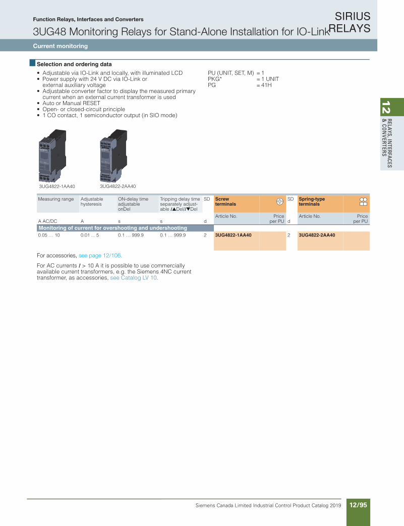
SIRIUS RELAYS
Siemens Canada Limited Industrial Control Product Catalog 2019 12/95
12
RELAYS, IN
TERFACES
& CO
NVERTERS
Function Relays, Interfaces and Converters
3UG48 Monitoring Relays for Stand-Alone Installation for IO-LinkCurrent monitoring
10/123Siemens IC 10 · 2018* You can order this quantity or a multiple thereof.Illustrations are approximate
RelaysSIRIUS 3UG48 Monitoring Relays for Stand-Alone Installation for IO-Link
Current monitoring
10
Selection and ordering data
• Adjustable via IO-Link and locally, with illuminated LCD• Power supply with 24 V DC via IO-Link or
external auxiliary voltage• Adjustable converter factor to display the measured primary
current when an external current transformer is used• Auto or Manual RESET• Open- or closed-circuit principle• 1 CO contact, 1 semiconductor output (in SIO mode)
PU (UNIT, SET, M) = 1PKG* = 1 UNITPG = 41H
For accessories, see page 10/134.
For AC currents I > 10 A it is possible to use commerciallyavailable current transformers, e.g. the Siemens 4NC current transformer, as accessories, see Catalog LV 10.
Measuring range Adjustable hysteresis
ON-delay timeadjustable onDel
Tripping delay time separately adjust-able IDel/IDel
SD Screw terminals
SD Spring-typeterminals
A AC/DC A s s dArticle No. Price
per PU dArticle No. Price
per PUMonitoring of current for overshooting and undershooting 0.05 … 10 0.01 ... 5 0.1 … 999.9 0.1 … 999.9 2 3UG4822-1AA40 2 3UG4822-2AA40
3UG4822-1AA40 3UG4822-2AA40
IC10_10_10.fm Page 123 Thursday, February 22, 2018 9:30 PM
For accessories, see page 12/106.

SIRIUS RELAYS
Siemens Canada Limited Industrial Control Product Catalog 201912/96
12
RELA
YS, I
NTE
RFA
CES
& C
ON
VERT
ERS
10/124 Siemens IC 10 · 2018
RelaysSIRIUS 3UG48 Monitoring Relays for Stand-Alone Installation for IO-Link
Power factor and active current monitoring
10
Overview
SIRIUS 3UG4841 monitoring relay
The 3UG4841 power factor and active current monitoring devices enable the load monitoring of motors.
Whereas power factor (p.f.) monitoring is used above all for monitoring no-load operation, the active current monitoring option can be used to observe and evaluate the load factor over the entire torque range.
Benefits
• Monitoring of even small single-phase motors with a no-load supply current below 0.5 A
• Simple determination of threshold values by the direct collection of measured variables on motor loading
• Range monitoring and active current measurement enable de-tection of cable breaks between control cabinets and motors, as well as phase failures
• Power factor and/or Ires (active current) can be selected as the measurement principle
• Width 22.5 mm• Display and transmission of actual value and status messages
to controller• All versions with removable terminals• All versions with screw or spring-type terminals
Application
• No-load monitoring and load shedding, such as in the event of a V-belt tear
• Underload monitoring in the low-end performance range, e.g. in the event of pump no-load operation
• Monitoring of overload, e.g. due to a dirty filter system• Power factor monitoring in networks for control of compensa-
tion equipment• Broken cable between control cabinet and motor
Technical specifications
3UG4841 monitoring relays
The 3UG4841 monitoring relays are supplied with power through IO-Link or with an external auxiliary voltage of 24 V DC and are used for performing overshoot, undershoot or range monitoring of the power factor and/or the resulting active current, depend-ing on parameterization. The load to be monitored is connected upstream of the IN terminal. The load current flows through the terminals IN and Ly/N. The setting range for the power factor is 0 to 0.99 and for the active current Ires it is 0.2 to 10 A. If the con-trol supply voltage is switched on and no load current flows, the display will show I < 0.2 and a symbol for overrange, under-range or range monitoring. If the motor is now switched on and the current exceeds 0.2 A, the set ON-delay time onDel begins. During this time, if the set limit values are undershot or ex-ceeded, this does not lead to a relay reaction of the changeover contact. If the operational flowing active current and/or the p.f. value falls below or exceeds the respective set threshold value, the tripping delay time begins. When this time has expired, the relay changes its switch position. The relevant measured vari-ables for overshooting and undershooting in the display flash. If monitoring for active current undershoot is switched off (Ires= OFF), and if the load current undershoots the lower measuring range threshold (0.2 A), the CO contacts remain unchanged. If a threshold value is set for the monitoring of active current under-shooting, then undershooting of the measuring range threshold (0.2 A) will result in a response of the CO contacts.
The relay operates either according to the open-circuit or closed-circuit principle.
If the device is set to Auto RESET (Memory = No), depending on the set principle of operation, the switching relay returns to its ini-tial state and the flashing ends when the hysteresis threshold is reached.
If Manual RESET is selected in the menu (Memory = Yes), the switching relay remains in its current switching state and the cur-rent measured value and the symbol for undershooting and overshooting continues to flash, even when the measured vari-able reaches a permissible value again. This stored fault status can be reset by simultaneously pressing the UP and DOWN keys for 2.5 s.
With Manual RESET through IO-Link it is possible in addition to set whether error signals are to be deleted when the control sup-ply voltage is switched off and on (as remote RESET) or whether the signals are to be permanently saved even in a voltage failure, with confirmation possible only through local RESET or via IO-Link.
IC10_10_10.fm Page 124 Thursday, February 22, 2018 9:30 PM
Function Relays, Interfaces and Converters
3UG48 Monitoring Relays for Stand-Alone Installation for IO-LinkPower factor and active current monitoring
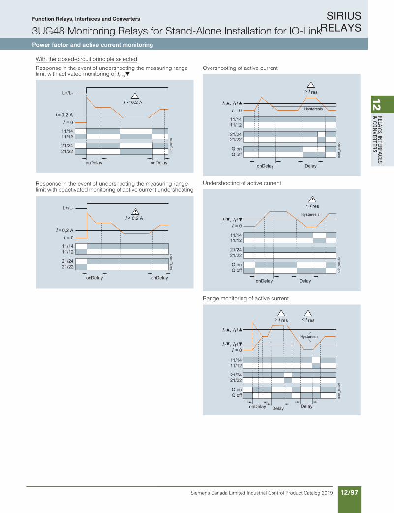
SIRIUS RELAYS
Siemens Canada Limited Industrial Control Product Catalog 2019 12/97
12
RELAYS, IN
TERFACES
& CO
NVERTERS
Function Relays, Interfaces and Converters
3UG48 Monitoring Relays for Stand-Alone Installation for IO-LinkPower factor and active current monitoring
10/125Siemens IC 10 · 2018
RelaysSIRIUS 3UG48 Monitoring Relays for Stand-Alone Installation for IO-Link
Power factor and active current monitoring
10
With the closed-circuit principle selected
Response in the event of undershooting the measuring range limit with activated monitoring of Ires
Response in the event of undershooting the measuring range limit with deactivated monitoring of active current undershooting
Overshooting of active current
Undershooting of active current
Range monitoring of active current
IC01
_000
20
< 0,2 A
L+/L-
21/2221/24
11/1211/14
= 0= 0,2 A
onDelay onDelay
IC01
_000
21
< 0,2 A
L+/L-
21/2221/24
11/1211/14
= 0= 0,2 A
onDelay onDelay
IC01
_000
22
Q offQ on
11/1211/14
= 0
21/2221/24
> res
, !r r
onDelay Delay
Hysteresis
IC01
_000
23
Q offQ on
11/1211/14
= 0
21/2221/24
< res
, !r r
onDelay Delay
Hysteresis
IC01
_000
24
Q offQ on
11/1211/14
= 0
21/2221/24
> res < res
, !r r
, !r r
onDelay DelayDelay
Hysteresis
IC10_10_10.fm Page 125 Thursday, February 22, 2018 9:30 PM
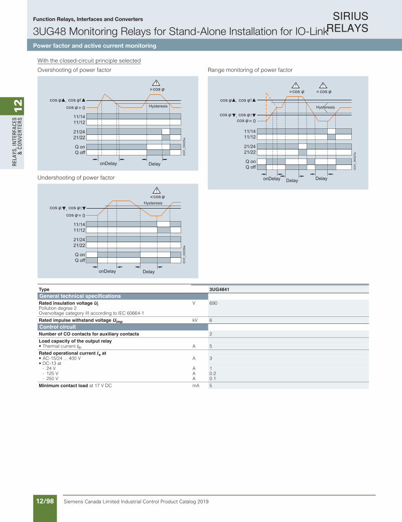
SIRIUS RELAYS
Siemens Canada Limited Industrial Control Product Catalog 201912/98
12
RELA
YS, I
NTE
RFA
CES
& C
ON
VERT
ERS
Function Relays, Interfaces and Converters
3UG48 Monitoring Relays for Stand-Alone Installation for IO-LinkPower factor and active current monitoring
10/126 Siemens IC 10 · 2018
RelaysSIRIUS 3UG48 Monitoring Relays for Stand-Alone Installation for IO-Link
Power factor and active current monitoring
10
With the closed-circuit principle selected
Overshooting of power factor
Undershooting of power factor
Range monitoring of power factor
IC01
_000
25a
Q offQ on
11/1211/14
21/2221/24
>cos
!
cos,cos cos
= 0
onDelay Delay
Hysteresis
IC01
_000
26a
Q offQ on
11/1211/14
21/2221/24
<cos
!cos = 0,cos cos
onDelay Delay
Hysteresis
IC01
_000
27a
Q offQ on
11/1211/14
21/2221/24
> <cos cos
!,cos cos
cos = 0!,cos cos
onDelay DelayDelay
Hysteresis
Type 3UG4841General technical specificationsRated insulation voltage UiPollution degree 2Overvoltage category III according to IEC 60664-1
V 690
Rated impulse withstand voltage Uimp kV 6Control circuitNumber of CO contacts for auxiliary contacts 2
Load capacity of the output relay• Thermal current Ith A 5
Rated operational current Ie at• AC-15/24 ... 400 V A 3• DC-13 at
- 24 V A 1- 125 V A 0.2- 250 V A 0.1
Minimum contact load at 17 V DC mA 5
IC10_10_10.fm Page 126 Thursday, February 22, 2018 9:30 PM
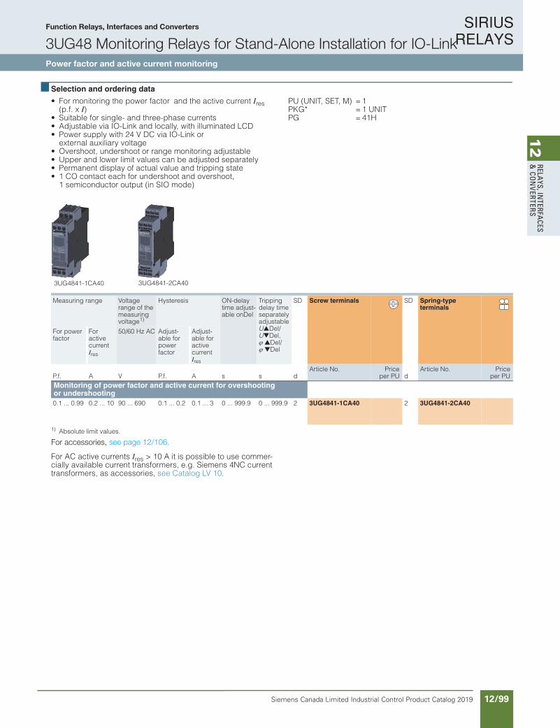
SIRIUS RELAYS
Siemens Canada Limited Industrial Control Product Catalog 2019 12/99
12
RELAYS, IN
TERFACES
& CO
NVERTERS
Function Relays, Interfaces and Converters
3UG48 Monitoring Relays for Stand-Alone Installation for IO-LinkPower factor and active current monitoring
10/127Siemens IC 10 · 2018* You can order this quantity or a multiple thereof.Illustrations are approximate
RelaysSIRIUS 3UG48 Monitoring Relays for Stand-Alone Installation for IO-Link
Power factor and active current monitoring
10
Selection and ordering data
• For monitoring the power factor and the active current Ires (p.f. x I)
• Suitable for single- and three-phase currents• Adjustable via IO-Link and locally, with illuminated LCD• Power supply with 24 V DC via IO-Link or
external auxiliary voltage• Overshoot, undershoot or range monitoring adjustable• Upper and lower limit values can be adjusted separately• Permanent display of actual value and tripping state• 1 CO contact each for undershoot and overshoot,
1 semiconductor output (in SIO mode)
PU (UNIT, SET, M) = 1PKG* = 1 UNITPG = 41H
1) Absolute limit values.
For accessories, see page 10/134.
For AC active currents Ires > 10 A it is possible to use commer-cially available current transformers, e.g. Siemens 4NC current transformers, as accessories, see Catalog LV 10.
Measuring range Voltage range of the measuring voltage1)
Hysteresis ON-delay time adjust-able onDel
Tripping delay time separately adjustable UDel/UDel, Del/ Del
SD Screw terminals SD Spring-type terminals
For power factor
For active current Ires
50/60 Hz AC Adjust-able for power factor
Adjust-able for active current Ires
P.f. A V P.f. A s s dArticle No. Price
per PU dArticle No. Price
per PUMonitoring of power factor and active current for overshooting or undershooting0.1 ... 0.99 0.2 ... 10 90 ... 690 0.1 ... 0.2 0.1 ... 3 0 ... 999.9 0 ... 999.9 2 3UG4841-1CA40 2 3UG4841-2CA40
3UG4841-1CA40 3UG4841-2CA40
IC10_10_10.fm Page 127 Thursday, February 22, 2018 9:30 PM
For accessories, see page 12/106.
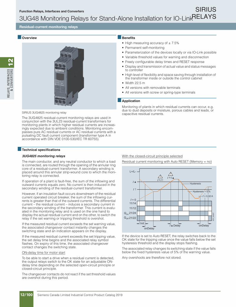
SIRIUS RELAYS
Siemens Canada Limited Industrial Control Product Catalog 201912/100
12
RELA
YS, I
NTE
RFA
CES
& C
ON
VERT
ERS
10/128 Siemens IC 10 · 2018
RelaysSIRIUS 3UG48 Monitoring Relays for Stand-Alone Installation for IO-LinkResidual-Current Monitoring
Residual-current monitoring relays
10
Overview
SIRIUS 3UG4825 monitoring relay
The 3UG4825 residual-current monitoring relays are used in conjunction with the 3UL23 residual-current transformers for monitoring plants in which higher residual currents are increas-ingly expected due to ambient conditions. Monitoring encom-passes pure AC residual currents or AC residual currents with a pulsating DC fault current component (transformer type A in accordance with DIN VDE 0100-530/IEC TR 60755).
Benefits
• High measuring accuracy of ± 7.5%• Permanent self-monitoring• Parameterization of the devices locally or via IO-Link possible• Variable threshold values for warning and disconnection• Freely configurable delay times and RESET response• Display and transmission of actual value and status messages
to controller• High level of flexibility and space saving through installation of
the transformer inside or outside the control cabinet• Width 22.5 m• All versions with removable terminals• All versions with screw or spring-type terminals
Application
Monitoring of plants in which residual currents can occur, e.g. due to dust deposits or moisture, porous cables and leads, or capacitive residual currents.
Technical specifications
3UG4825 monitoring relays
The main conductor, and any neutral conductor to which a load is connected, are routed through the opening of the annular ring core of a residual-current transformer. A secondary winding is placed around this annular strip-wound core to which the moni-toring relay is connected.
If operation of a plant is fault-free, the sum of the inflowing and outward currents equals zero. No current is then induced in the secondary winding of the residual-current transformer.
However, if an insulation fault occurs downstream of the residual current operated circuit breaker, the sum of the inflowing cur-rents is greater than that of the outward currents. The differential current – the residual current – induces a secondary current in the secondary winding of the transformer. This current is evalu-ated in the monitoring relay and is used on the one hand to display the actual residual current and on the other, to switch the relay if the set warning or tripping threshold is overshot.
If the measured residual current exceeds the set warning value, the associated changeover contact instantly changes the switching state and an indication appears on the display.
If the measured residual current exceeds the set tripping value, the set delay time begins and the associated relay symbol flashes. On expiry of this time, the associated changeover contact changes the switching state.
ON-delay time for motor start
To be able to start a drive when a residual current is detected, the output relays switch to the OK state for an adjustable ON-delay time depending on the selected open-circuit principle or closed-circuit principle.
The changeover contacts do not react if the set threshold values are overshot during this period.
With the closed-circuit principle selected
Residual current monitoring with Auto RESET (Memory = no)
If the device is set to Auto RESET, the relay switches back to the OK state for the tripping value once the value falls below the set hysteresis threshold and the display stops flashing.
The associated relay changes its switching state if the value falls below the fixed hysteresis value of 5% of the warning value.
Any overshoots are therefore not stored.
!
> > !
Hysteresis
= 0,02 A
Hysteresis = 5 %
onDelayonDelay
InitDelay
L+/L-
11/14
11/12
Qon 21/24
Qoff 21/22
= 0
IC01
_002
27
IC10_10_10.fm Page 128 Thursday, February 22, 2018 9:30 PM
Function Relays, Interfaces and Converters
3UG48 Monitoring Relays for Stand-Alone Installation for IO-LinkResidual-current monitoring relays
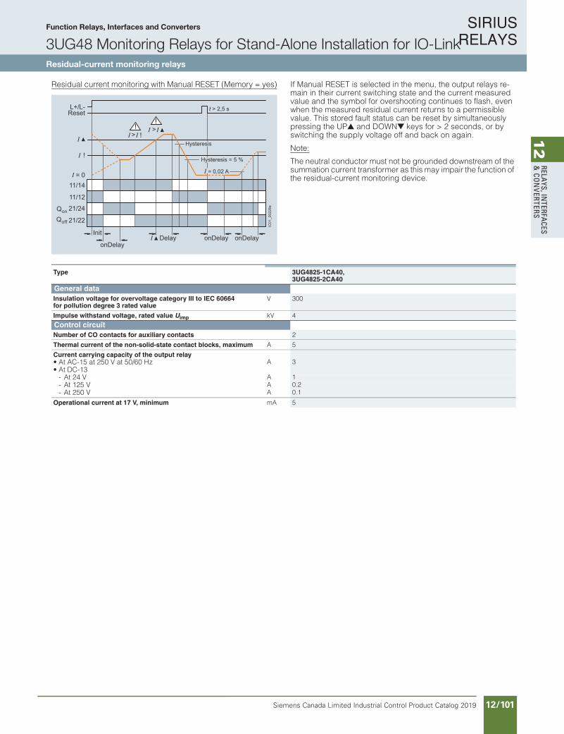
SIRIUS RELAYS
Siemens Canada Limited Industrial Control Product Catalog 2019 12/101
12
RELAYS, IN
TERFACES
& CO
NVERTERS
10/129Siemens IC 10 · 2018
RelaysSIRIUS 3UG48 Monitoring Relays for Stand-Alone Installation for IO-Link
Residual-Current Monitoring
Residual-current monitoring relays
10
Residual current monitoring with Manual RESET (Memory = yes) If Manual RESET is selected in the menu, the output relays re-main in their current switching state and the current measured value and the symbol for overshooting continues to flash, even when the measured residual current returns to a permissible value. This stored fault status can be reset by simultaneously pressing the UP and DOWN keys for > 2 seconds, or by switching the supply voltage off and back on again.
Note:
The neutral conductor must not be grounded downstream of the summation current transformer as this may impair the function of the residual-current monitoring device.
> > !
!
Hysteresis
= 0,02 A
Hysteresis = 5 %
Delay onDelayonDelayonDelay
Init
t > 2,5 s
IC01
_002
28a
L+/L-Reset
11/14
11/12
Qon 21/24
Qoff 21/22
= 0
Type 3UG4825-1CA40,3UG4825-2CA40
General dataInsulation voltage for overvoltage category III to IEC 60664 for pollution degree 3 rated value
V 300
Impulse withstand voltage, rated value Uimp kV 4Control circuitNumber of CO contacts for auxiliary contacts 2
Thermal current of the non-solid-state contact blocks, maximum A 5
Current carrying capacity of the output relay• At AC-15 at 250 V at 50/60 Hz A 3• At DC-13
- At 24 V A 1- At 125 V A 0.2- At 250 V A 0.1
Operational current at 17 V, minimum mA 5
IC10_10_10.fm Page 129 Thursday, February 22, 2018 9:30 PM
Function Relays, Interfaces and Converters
3UG48 Monitoring Relays for Stand-Alone Installation for IO-LinkResidual-current monitoring relays
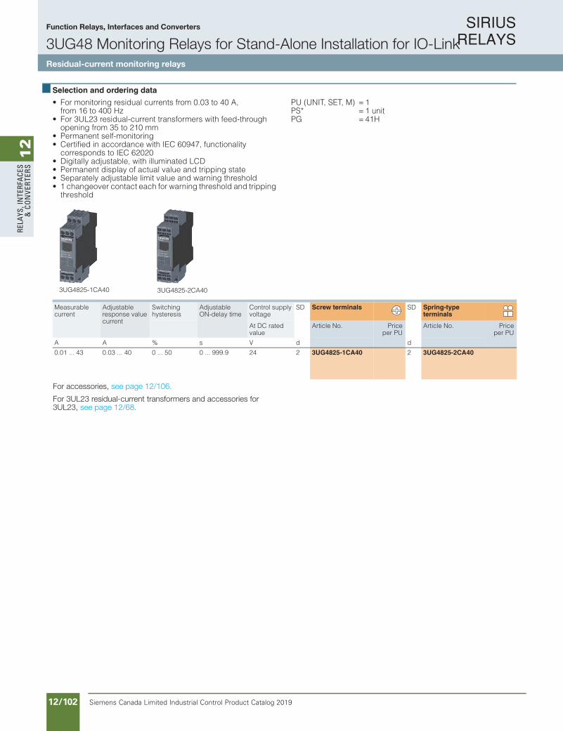
SIRIUS RELAYS
Siemens Canada Limited Industrial Control Product Catalog 201912/102
12
RELA
YS, I
NTE
RFA
CES
& C
ON
VERT
ERS
Function Relays, Interfaces and Converters
3UG48 Monitoring Relays for Stand-Alone Installation for IO-LinkResidual-current monitoring relays
10/130 Siemens IC 10 · 2018* You can order this quantity or a multiple thereof.
Illustrations are approximate
RelaysSIRIUS 3UG48 Monitoring Relays for Stand-Alone Installation for IO-LinkResidual-Current Monitoring
Residual-current monitoring relays
10
Selection and ordering data
• For monitoring residual currents from 0.03 to 40 A, from 16 to 400 Hz
• For 3UL23 residual-current transformers with feed-through opening from 35 to 210 mm
• Permanent self-monitoring• Certified in accordance with IEC 60947, functionality
corresponds to IEC 62020• Digitally adjustable, with illuminated LCD• Permanent display of actual value and tripping state• Separately adjustable limit value and warning threshold• 1 changeover contact each for warning threshold and tripping
threshold
PU (UNIT, SET, M) = 1 PS* = 1 unit PG = 41H
For accessories, see page 10/134.
For 3UL23 residual-current transformers and accessories for 3UL23, see page 10/96.
Measurable current
Adjustable response value current
Switching hysteresis
Adjustable ON-delay time
Control supply voltage
SD Screw terminals SD Spring-type terminals
At DC rated value
Article No. Priceper PU
Article No. Priceper PU
A A % s V d d
0.01 ... 43 0.03 ... 40 0 ... 50 0 ... 999.9 24 2 3UG4825-1CA40 2 3UG4825-2CA40
3UG4825-1CA40 3UG4825-2CA40
IC10_10_10.fm Page 130 Thursday, February 22, 2018 9:30 PM
For accessories, see page 12/106.
For 3UL23 residual-current transformers and accessories for 3UL23, see page 12/68.

SIRIUS RELAYS
Siemens Canada Limited Industrial Control Product Catalog 2019 12/103
12
RELAYS, IN
TERFACES
& CO
NVERTERS
10/131Siemens IC 10 · 2018
RelaysSIRIUS 3UG48 Monitoring Relays for Stand-Alone Installation for IO-Link
Speed monitoring
10
Overview
SIRIUS 3UG4851 monitoring relay
3UG4851 monitoring relays are used in combination with a sensor to monitor drives for overspeed and/or underspeed.
Furthermore, the monitoring relays are ideal for all functions where a continuous pulse signal needs to be monitored (e.g. belt travel monitoring, completeness monitoring, passing monitoring, clock-time monitoring).
Benefits
• Variably adjustable to overshoot, undershoot or range monitoring
• Freely configurable delay times and RESET response• Display and transmission of actual value and fault type to
controller• Use of up to 10 sensors per rotation for extremely slowly
rotating motors• 2- or 3-wire sensors and sensors with a mechanical switching
output or semiconductor output can be connected• Auxiliary voltage for sensor integrated• All versions with removable terminals• All versions with screw or spring-type terminals
Application
• Slip or tear of a belt drive• Overload monitoring• Transport monitoring for completeness
Technical specifications
3UG4851 monitoring relays
The speed monitoring relay operates according to the principle of period duration measurement.
In the monitoring relay, the time between two successive rising edges of the pulse encoder is measured and compared to the minimum and/or maximum permissible period duration calcu-lated from the set limit values for the speed.
Thus, the period duration measurement recognizes any devia-tion in speed after just two pulses, even at very low speeds or in the case of extended pulse gaps.
By using up to ten pulse encoders evenly distributed around the circumference, it is possible to shorten the period duration, and in turn the response time. By taking into account the number of sensors in the monitoring relay, the speed continues to be indi-cated in rpm.
ON-delay time for motor start
To be able to start a motor drive, and depending on whether the open-circuit or closed-circuit principle is selected, the output re-lay switches to the GO state during the ON-delay time, even if the speed is still below the set value.
The ON-delay time is started by either switching on the auxiliary voltage or, if the auxiliary voltage is already applied, by actuating the respective NC contact (e.g. auxiliary contact).
Speed monitoring with Auto RESET (Memory = no)
If the device is set to Auto RESET, the output relay switches to the GO state, once the adjustable hysteresis threshold is reached in the range of 1 to 99.9 rpm and the flashing stops. Any overshoots or undershoots are therefore not stored.
Speed monitoring with Manual RESET (Memory = yes)
If Manual RESET is selected in the menu, the output relay re-mains in its current switching state and the current measured value and the symbol for overshooting/undershooting continue to flash, even when the speed returns to a permissible value. This stored fault status can be reset by simultaneously pressing the UP and DOWN keys for > 2.5 s or by connecting the RESET device terminal to 24 V DC.
With Manual RESET through IO-Link it is possible in addition to set whether error signals are to be deleted when the control sup-ply voltage is switched off and on (as remote RESET) or whether the signals are to be permanently saved even in a voltage failure, with confirmation possible only through local RESET or viaIO-Link.
IC10_10_10.fm Page 131 Thursday, February 22, 2018 9:30 PM
Function Relays, Interfaces and Converters
3UG48 Monitoring Relays for Stand-Alone Installation for IO-LinkSpeed monitoring

SIRIUS RELAYS
Siemens Canada Limited Industrial Control Product Catalog 201912/104
12
RELA
YS, I
NTE
RFA
CES
& C
ON
VERT
ERS
Function Relays, Interfaces and Converters
3UG48 Monitoring Relays for Stand-Alone Installation for IO-LinkSpeed monitoring
10/132 Siemens IC 10 · 2018
RelaysSIRIUS 3UG48 Monitoring Relays for Stand-Alone Installation for IO-Link
Speed monitoring
10
With the closed-circuit principle selected
Range monitoring without enable input Range monitoring with enable input
IC01
_000
30
Q offQ on
11/1211/14
RPM = 0
L+/L-
> RPM < RPMrpm rpm!
rpm rpm!
onDelay DelayDelay
Hysteresis
IC01
_000
31
11/1411/12
Q onQ off
RPM = 0
L+/L-
rpm rpm!
rpm rpm!
EN
> RPM < RPM
onDelay DelayDelay
Hysteresis
Type 3UG4851General technical specificationsRated insulation voltage UiPollution degree 2Overvoltage category III acc. to VDE 0110
V 300
Rated impulse withstand voltage Uimp kV 4Measuring circuitSensor supply• For 3-wire sensor (24 V/0 V) mA Max. 50• For 2-wire NAMUR sensor (8V2) mA Max. 8.2
Signal input• IN1 k 16, 3-wire sensor, pnp operation• IN2 k 1, floating contact, 2-wire NAMUR sensor
Voltage level• For level 1 at IN1 V 4.5 ... 30• For level 0 at IN1 V 0 ... 1
Current level• For level 1 at IN2 mA > 2.1• For level 0 at IN2 mA < 1.2
Minimum pulse duration of signal ms 5
Minimum interval between 2 pulses ms 5Control circuitNumber of CO contacts for auxiliary contacts 1
Load capacity of the output relayThermal current Ith A 5
Rated operational current Ie at• AC-15/24 ... 250 V A 3• DC-13 at
- 24 V A 1- 125 V A 0.2- 250 V A 0.1
Minimum contact load at 17 V DC mA 5
IC10_10_10.fm Page 132 Thursday, February 22, 2018 9:30 PM

SIRIUS RELAYS
Siemens Canada Limited Industrial Control Product Catalog 2019 12/105
12
RELAYS, IN
TERFACES
& CO
NVERTERS
Function Relays, Interfaces and Converters
3UG48 Monitoring Relays for Stand-Alone Installation for IO-LinkSpeed monitoring
10/133Siemens IC 10 · 2018* You can order this quantity or a multiple thereof.Illustrations are approximate
RelaysSIRIUS 3UG48 Monitoring Relays for Stand-Alone Installation for IO-Link
Speed monitoring
10
Selection and ordering data
• For speed monitoring in revolutions per minute (rpm)• Two- or three-wire sensor with mechanical or electronic
switching output can be connected• Two-wire NAMUR sensor can be connected• Sensor supply 24 V DC/50 mA integrated• Input frequency 0.1 to 2 200 pulses per minute
(0.0017 to 36.7 Hz)• With or without enable signal for the drive to be monitored• Adjustable via IO-Link and locally, with illuminated LCD• Power supply with 24 V DC via IO-Link or
external auxiliary voltage• Overshoot, undershoot or range monitoring adjustable• Number of pulses per revolution can be adjusted• Upper and lower limit values can be adjusted separately• Auto, manual or remote RESET options after tripping• Permanent display of actual value and tripping state• 1 CO contact, 1 semiconductor output (in SIO mode)
PU (UNIT, SET, M) = 1PKG* = 1 UNITPG = 41H
For accessories, see page 10/134.
Measuring range Adjustable hysteresis
ON-delay time adjustable onDel
Tripping delay time separatelyadjustable rpmDel/rpmDel
Pulses per revolution
SD Screw terminals SD Spring-type terminals
rpm rpm s s dArticle No. Price
per PU dArticle No. Price
per PU
Speed monitoring for overshooting and undershooting0.1 ... 2 200 OFF
1 ... 99.90 ... 999.9 0 ... 999.9 1 ... 10 2 3UG4851-1AA40 2 3UG4851-2AA40
3UG4851-1AA40 3UG4851-2AA40
IC10_10_10.fm Page 133 Thursday, February 22, 2018 9:30 PM
For accessories, see page 12/106.
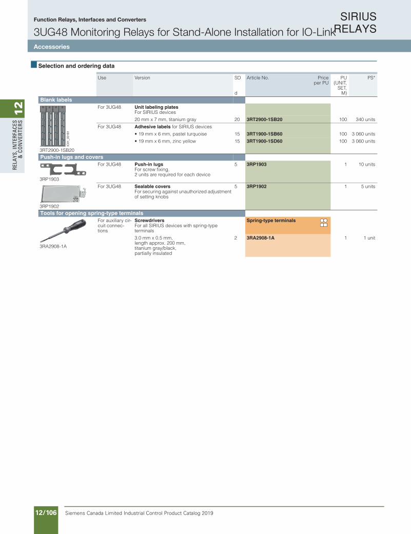
SIRIUS RELAYS
Siemens Canada Limited Industrial Control Product Catalog 201912/106
12
RELA
YS, I
NTE
RFA
CES
& C
ON
VERT
ERS
10/134 Siemens IC 10 · 2018* You can order this quantity or a multiple thereof.
Illustrations are approximate
RelaysSIRIUS 3UG48 Monitoring Relays for Stand-Alone Installation for IO-Link
Accessories
10
Selection and ordering data
Use Version SD
d
Article No. Priceper PU
PU(UNIT,
SET,M)
PS*
Blank labels
3RT2900-1SB20
For 3UG48 Unit labeling plates For SIRIUS devices
20 mm x 7 mm, titanium gray 20 3RT2900-1SB20 100 340 units
For 3UG48 Adhesive labels for SIRIUS devices
• 19 mm x 6 mm, pastel turquoise 15 3RT1900-1SB60 100 3 060 units
• 19 mm x 6 mm, zinc yellow 15 3RT1900-1SD60 100 3 060 units
Push-in lugs and covers
3RP1903
For 3UG48 Push-in lugs For screw fixing,2 units are required for each device
5 3RP1903 1 10 units
3RP1902
For 3UG48 Sealable covers For securing against unauthorized adjustment of setting knobs
5 3RP1902 1 5 units
Tools for opening spring-type terminals
3RA2908-1A
For auxiliary cir-cuit connec-tions
Screwdrivers For all SIRIUS devices with spring-typeterminals
Spring-type terminals
3.0 mm x 0.5 mm, length approx. 200 mm,titanium gray/black,partially insulated
2 3RA2908-1A 1 1 unit
IC01
_001
81
IC10_10_10.fm Page 134 Thursday, February 22, 2018 9:30 PM
Function Relays, Interfaces and Converters
3UG48 Monitoring Relays for Stand-Alone Installation for IO-LinkAccessories

SIRIUS RELAYS
Siemens Canada Limited Industrial Control Product Catalog 2019 12/107
12
RELAYS, IN
TERFACES
& CO
NVERTERS
Siemens / Industrial Controls Previous folio: IC10 11/57
5/32 Siemens IC 10 · 2016
Coupling RelaysSIRIUS 3RQ3 Coupling Relays, Narrow Design
General data
5
Overview
SIRIUS 3RQ3 coupling relays
SIRIUS 3RQ3 coupling relays in narrow design are used for coupling control signals from and to a controller, and they are available in different versions:• Coupling relays with relay output (not plug-in)• Coupling relays with plug-in relays• Coupling relays with semiconductor output (not plug-in)
Coupling relays with relay outputAC and DC operationIEC 60947-5-1, EN 60947-5-1
The input and output coupling relays differ with regard to the positioning of the terminals and the LEDs.
Coupling relays with plug-in relaysAC and DC operationIEC 60947-1
The coupling relays are plug-in, so the relay can be replaced quickly at the end of its service life without detaching the wiring.
Coupling relays with semiconductor outputAC and DC operationIEC 60947-1, EN 60664-1 and EN 50005; coupling relays with semiconductor output: EN 60747-5; programmable controllers: IEC 61131-2
The input and output coupling relays differ with regard to the positioning of the terminals and the LEDs.
The coupling relays with semiconductor output have extremely high contact reliability, so they are especially suitable for electronic systems.
For test purposes, versions are available with manual-0-automatic switches.
Spring-type terminal with push-in functionalityPush-in connections are a form of spring-type terminals allowing fast wiring without tools for rigid conductors or conductors equipped with end sleeves.
As with other spring-type terminals, a screwdriver (with 3.0 x 0.5 mm blade) is required to disconnect the conductor. The same tool can also be used to wire finely-stranded conductors with no end finishing.
The advantages of the push-in terminals are found, as with all spring-type terminals, in speed of assembly and disassembly and vibration-proof connection. There is no need for the checking and tightening required with screw terminals.
Note:
For the conversion tool e.g. from 3TX7 to 3RQ3, see www.siemens.com/sirius/conversion-tool.
Article No. scheme
Note:
The Article No. scheme is presented here merely for information purposes and for better understanding of the logic behind the article numbers.
For your orders, please use the article numbers quoted in the catalog in the Selection and ordering data.
Digit of the Article No. 1st - 4th@@@@
5th@
6th@
7th@ Ð
8th@
9th@
10th@
11th@
12th@
Coupling relays in the new 6.2 mm enclosure 3RQ3Function @Design and type of output @Switching current at the output @Connection methods @Contacts @Rated control supply voltage @Max. switchable voltage at the output @Contact variant @Example 3RQ3 1 1 8 Ð 1 A M 0 0
IC10_05_04.fm Page 32 Tuesday, June 14, 2016 11:54 AM
Function Relays, Interfaces and Converters
Coupling Relays – Narrow Design3RQ3
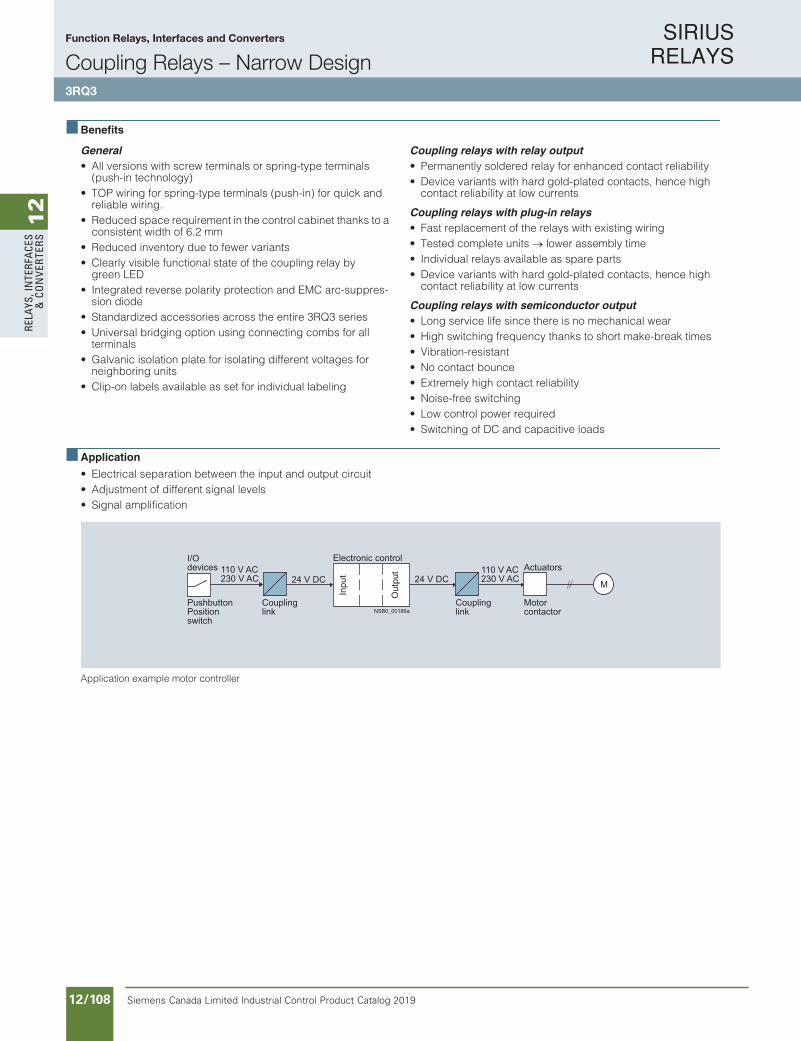
SIRIUS RELAYS
Siemens Canada Limited Industrial Control Product Catalog 201912/108
12
RELA
YS, I
NTE
RFA
CES
& C
ON
VERT
ERS
Siemens / Industrial Controls Previous folio: IC10 11/58
5/33Siemens IC 10 · 2016
Coupling RelaysSIRIUS 3RQ3 Coupling Relays, Narrow Design
General data
5
Benefits
General• All versions with screw terminals or spring-type terminals
(push-in technology)• TOP wiring for spring-type terminals (push-in) for quick and
reliable wiring.• Reduced space requirement in the control cabinet thanks to a
consistent width of 6.2 mm• Reduced inventory due to fewer variants• Clearly visible functional state of the coupling relay by
green LED• Integrated reverse polarity protection and EMC arc-suppres-
sion diode• Standardized accessories across the entire 3RQ3 series• Universal bridging option using connecting combs for all
terminals• Galvanic isolation plate for isolating different voltages for
neighboring units• Clip-on labels available as set for individual labeling
Coupling relays with relay output• Permanently soldered relay for enhanced contact reliability • Device variants with hard gold-plated contacts, hence high
contact reliability at low currents
Coupling relays with plug-in relays• Fast replacement of the relays with existing wiring• Tested complete units lower assembly time• Individual relays available as spare parts• Device variants with hard gold-plated contacts, hence high
contact reliability at low currents
Coupling relays with semiconductor output• Long service life since there is no mechanical wear• High switching frequency thanks to short make-break times• Vibration-resistant • No contact bounce • Extremely high contact reliability • Noise-free switching • Low control power required • Switching of DC and capacitive loads
Application
• Electrical separation between the input and output circuit• Adjustment of different signal levels• Signal amplification
Application example motor controller
M
Inpu
t
Out
put
PushbuttonPositionswitch
Coupling link
Coupling link
Motorcontactor
I/O devices
Electronic controlActuators110 V AC
230 V AC 24 V DC 24 V DC110 V AC 230 V AC
NSB0_00186a
IC10_05_04.fm Page 33 Tuesday, June 14, 2016 11:54 AM
Function Relays, Interfaces and Converters
Coupling Relays – Narrow Design3RQ3

SIRIUS RELAYS
Siemens Canada Limited Industrial Control Product Catalog 2019 12/109
12
RELAYS, IN
TERFACES
& CO
NVERTERS
Siemens / Industrial Controls Previous folio: IC10 11/59
5/34 Siemens IC 10 · 2016
Coupling RelaysSIRIUS 3RQ3 Coupling Relays, Narrow Design
General data
5
Technical specifications
Type 3RQ3018-.AB0.,3RQ3018-.AE00,3RQ3018-.AF00,3RQ3038-.AB0.,3RQ3038-.AE0.,3RQ3038-.AF0.,3RQ3052-.SM50,3RQ3053-.SG30
3RQ3018-2A.08-0AA0
3RQ3050-.SM50,3RQ3052-.SM30,3RQ3052-.SM40,3RQ3055-.SM30,3RQ3070-.SB30
3RQ3065-.SM30
3RQ3070-.SG30
3RQ3118-.AB0.,3RQ3118-.AE0.,3RQ3118-.AF0.,3RQ3118-.AM0.
General dataDimensions (W x H x D) mm 6.2 x 93 x 72.5 6.2 x 93 x 75 6.2 x 93 x 72.5 6.2 x 93 x 76
Insulation voltage for overvoltage category IIIto IEC 60664 for pollution degree 3 rated value
V 300 50 -- 300
Max. permissible voltage for protectiveseparation between control circuit andauxiliary circuit
V 300 50 -- 300
Permissible ambient temperature
• During operation °C -25 ... +60 -40 ... +70 -25 ... +60
• During storage °C -40 ... +85
IP degree of protection IP20
Version of the fuse link required for short-circuit protection of the auxiliary switch
Fuse gG: 4 A
Conductor cross-sectionsMain and auxiliary conductors(1 or 2 conductors connectable)
Screw terminals
• Solid mm² 1x (0.25 ... 2.5)
• Finely stranded with end sleeve mm² 1x (0.25 ... 1.5)
• AWG cables AWG 1x (20 ... 14)
Main and auxiliary conductors(1 or 2 conductors connectable)
Spring-type terminals
• Solid mm² 1x (0.25 ... 2.5)
• Finely stranded without end sleeve mm² 1x (0.25 ... 2.5)
• Finely stranded with end sleeve mm² 1x (0.25 ... 1.5)
• AWG cables AWG 1x (20 ... 14)
W
H
D
IC10_05_04.fm Page 34 Tuesday, June 14, 2016 11:54 AM
Function Relays, Interfaces and Converters
Coupling Relays – Narrow Design3RQ3
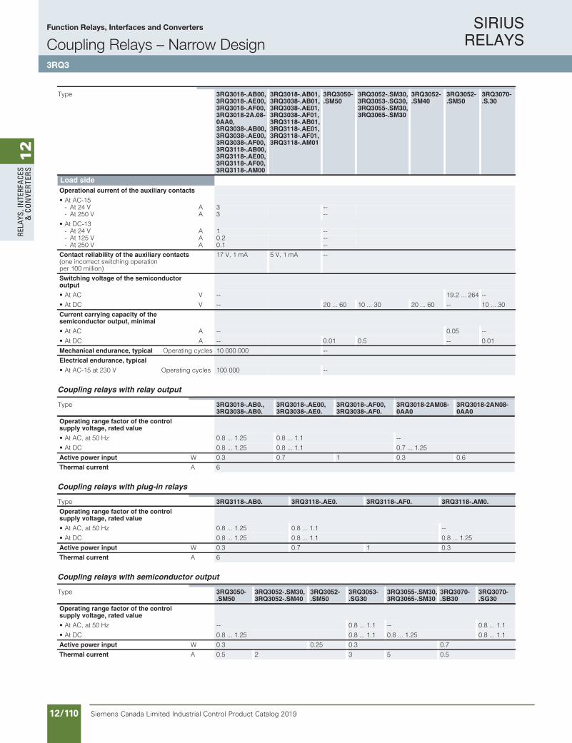
SIRIUS RELAYS
Siemens Canada Limited Industrial Control Product Catalog 201912/110
12
RELA
YS, I
NTE
RFA
CES
& C
ON
VERT
ERS
Siemens / Industrial Controls Previous folio: IC10 11/60
5/35Siemens IC 10 · 2016
Coupling RelaysSIRIUS 3RQ3 Coupling Relays, Narrow Design
General data
5
Coupling relays with relay output
Coupling relays with plug-in relays
Coupling relays with semiconductor output
Type 3RQ3018-.AB00,3RQ3018-.AE00,3RQ3018-.AF00,3RQ3018-2A.08-0AA0,3RQ3038-.AB00,3RQ3038-.AE00,3RQ3038-.AF00,3RQ3118-.AB00,3RQ3118-.AE00,3RQ3118-.AF00,3RQ3118-.AM00
3RQ3018-.AB01,3RQ3038-.AB01,3RQ3038-.AE01,3RQ3038-.AF01,3RQ3118-.AB01,3RQ3118-.AE01,3RQ3118-.AF01,3RQ3118-.AM01
3RQ3050-.SM50
3RQ3052-.SM30,3RQ3053-.SG30,3RQ3055-.SM30,3RQ3065-.SM30
3RQ3052-.SM40
3RQ3052-.SM50
3RQ3070-.S.30
Load sideOperational current of the auxiliary contacts
• At AC-15- At 24 V A 3 --- At 250 V A 3 --
• At DC-13- At 24 V A 1 --- At 125 V A 0.2 --- At 250 V A 0.1 --
Contact reliability of the auxiliary contacts(one incorrect switching operation per 100 million)
17 V, 1 mA 5 V, 1 mA --
Switching voltage of the semiconductoroutput
• At AC V -- 19.2 ... 264 --
• At DC V -- 20 ... 60 10 ... 30 20 ... 60 -- 10 ... 30
Current carrying capacity of thesemiconductor output, minimal
• At AC A -- 0.05 --
• At DC A -- 0.01 0.5 -- 0.01
Mechanical endurance, typical Operating cycles 10 000 000 --
Electrical endurance, typical
• At AC-15 at 230 V Operating cycles 100 000 --
Type 3RQ3018-.AB0.,3RQ3038-.AB0.
3RQ3018-.AE00,3RQ3038-.AE0.
3RQ3018-.AF00,3RQ3038-.AF0.
3RQ3018-2AM08-0AA0
3RQ3018-2AN08-0AA0
Operating range factor of the controlsupply voltage, rated value
• At AC, at 50 Hz 0.8 ... 1.25 0.8 ... 1.1 --
• At DC 0.8 ... 1.25 0.8 ... 1.1 0.7 ... 1.25
Active power input W 0.3 0.7 1 0.3 0.6
Thermal current A 6
Type 3RQ3118-.AB0. 3RQ3118-.AE0. 3RQ3118-.AF0. 3RQ3118-.AM0.
Operating range factor of the controlsupply voltage, rated value
• At AC, at 50 Hz 0.8 ... 1.25 0.8 ... 1.1 --
• At DC 0.8 ... 1.25 0.8 ... 1.1 0.8 ... 1.25
Active power input W 0.3 0.7 1 0.3
Thermal current A 6
Type 3RQ3050-.SM50
3RQ3052-.SM30,3RQ3052-.SM40
3RQ3052-.SM50
3RQ3053-.SG30
3RQ3055-.SM30,3RQ3065-.SM30
3RQ3070-.SB30
3RQ3070-.SG30
Operating range factor of the controlsupply voltage, rated value
• At AC, at 50 Hz -- 0.8 ... 1.1 -- 0.8 ... 1.1
• At DC 0.8 ... 1.25 0.8 ... 1.1 0.8 ... 1.25 0.8 ... 1.1
Active power input W 0.3 0.25 0.3 0.7
Thermal current A 0.5 2 3 5 0.5
IC10_05_04.fm Page 35 Tuesday, June 14, 2016 11:54 AM
Function Relays, Interfaces and Converters
Coupling Relays – Narrow Design3RQ3

SIRIUS RELAYS
Siemens Canada Limited Industrial Control Product Catalog 2019 12/111
12
RELAYS, IN
TERFACES
& CO
NVERTERS
Siemens / Industrial Controls Previous folio: IC10 11/61
5/36 Siemens IC 10 · 2016
Coupling RelaysSIRIUS 3RQ3 Coupling Relays, Narrow Design
General data
5
Circuit diagrams
Coupling relays with relay output (not plug-in)
3RQ30.8
Coupling relays with plug-in relays
3RQ3118
Coupling relays with semiconductor output (not plug-in)
3RQ305.-.S.30
3RQ305.-.SM.0, 3RQ3070-.S.30
3RQ3052-.SM50
3RQ3065-.SM30
11A1
1412A2A2
IC01_00441
IC01_00440A2 - 1412
11A1+
0A2A2 14 13+
A1
+ +
- IC01_00443
13+A2A2 14 13+
A1
+ +
- IC01_00442
13
A2
A2
14 13
A1
IC01_00446
0A2A2 14 13+
A1 A3
+ +
-
HA0
IC01_00445
IC10_05_04.fm Page 36 Tuesday, June 14, 2016 11:54 AM
Function Relays, Interfaces and Converters
Coupling Relays – Narrow Design3RQ3

SIRIUS RELAYS
Siemens Canada Limited Industrial Control Product Catalog 201912/112
12
RELA
YS, I
NTE
RFA
CES
& C
ON
VERT
ERS
Siemens / Industrial Controls Previous folio: IC10 11/62
5/37Siemens IC 10 · 2016* You can order this quantity or a multiple thereof.Illustrations are approximate
Coupling RelaysSIRIUS 3RQ3 Coupling Relays, Narrow Design
Coupling relays with relay output
5
Selection and ordering data
PU (UNIT, SET, M)= 1PS* = 5 unitsPG = 41H
Available
-- Not available
3RQ30.8-1 3RQ30.8-2
Control supply voltagerated value
Number of CO contacts for auxiliary contacts
Contactshard gold-plated
DT Screw terminals DT Spring-type terminals(push-in)
Article No. Priceper PU
Article No. Priceper PUV
Coupling relays with relay outputOutput coupling links24 AC/DC 1 -- A 3RQ3018-1AB00 A 3RQ3018-2AB00
A 3RQ3018-1AB01 A 3RQ3018-2AB01
115 AC/DC 1 -- A 3RQ3018-1AE00 A 3RQ3018-2AE00
230 AC/DC 1 -- A 3RQ3018-1AF00 A 3RQ3018-2AF00
24 DC 1 -- -- A 3RQ3018-2AM08-0AA0
110 DC 1 -- -- A 3RQ3018-2AN08-0AA0
Input coupling links24 AC/DC 1 -- A 3RQ3038-1AB00 A 3RQ3038-2AB00
A 3RQ3038-1AB01 A 3RQ3038-2AB01
115 AC/DC 1 -- A 3RQ3038-1AE00 A 3RQ3038-2AE00
A 3RQ3038-1AE01 A 3RQ3038-2AE01
230 AC/DC 1 -- A 3RQ3038-1AF00 A 3RQ3038-2AF00
A 3RQ3038-1AF01 A 3RQ3038-2AF01
IC10_05_04.fm Page 37 Tuesday, June 14, 2016 11:54 AM
Function Relays, Interfaces and Converters
Coupling Relays – Narrow Design3RQ3 with relay output

SIRIUS RELAYS
Siemens Canada Limited Industrial Control Product Catalog 2019 12/113
12
RELAYS, IN
TERFACES
& CO
NVERTERS
Siemens / Industrial Controls Previous folio: IC10 11/63
5/38 Siemens IC 10 · 2016* You can order this quantity or a multiple thereof.
Illustrations are approximate
Coupling RelaysSIRIUS 3RQ3 Coupling Relays, Narrow Design
Coupling relays with plug-in relays
5
Selection and ordering data
PU (UNIT, SET, M)= 1PS* = 5 unitsPG = 41H
Available
-- Not available
3RQ3118-1 3RQ3118-2
Control supply voltagerated value
Number of CO contacts for auxiliary contacts
Contactshard gold-plated
DT Screw terminals DT Spring-type terminals(push-in)
Article No. Priceper PU
Article No. Priceper PUV
Coupling relays with plug-in relaysOutput coupling links24 AC/DC 1 -- A 3RQ3118-1AB00 A 3RQ3118-2AB00
A 3RQ3118-1AB01 A 3RQ3118-2AB01
115 AC/DC 1 -- A 3RQ3118-1AE00 A 3RQ3118-2AE00
A 3RQ3118-1AE01 A 3RQ3118-2AE01
230 AC/DC 1 -- A 3RQ3118-1AF00 A 3RQ3118-2AF00
A 3RQ3118-1AF01 A 3RQ3118-2AF01
24 DC 1 -- A 3RQ3118-1AM00 A 3RQ3118-2AM00
A 3RQ3118-1AM01 A 3RQ3118-2AM01
IC10_05_04.fm Page 38 Tuesday, June 14, 2016 11:54 AM
Function Relays, Interfaces and Converters
Coupling Relays – Narrow Design3RQ3 with plug-in relays

SIRIUS RELAYS
Siemens Canada Limited Industrial Control Product Catalog 201912/114
12
RELA
YS, I
NTE
RFA
CES
& C
ON
VERT
ERS
Siemens / Industrial Controls Previous folio: IC10 11/64
5/39Siemens IC 10 · 2016* You can order this quantity or a multiple thereof.Illustrations are approximate
Coupling RelaysSIRIUS 3RQ3 Coupling Relays, Narrow Design
Coupling relays with semiconductor output
5
Selection and ordering data
PU (UNIT, SET, M)= 1PS* = 5 unitsPG = 41H
Available
-- Not available
3RQ3050-1SM50 3RQ3050-2SM50
Control supply voltagerated value
Current carrying capacity of the semiconductor output
Manual-0-automatic switch
DT Screw terminals DT Spring-type terminals(push-in)
Resistive load
At DC-13 At AC-15
At 24 V At 60 VAt 240 V At 50/60 Hz
Article No. Priceper PU
Article No. Priceper PUV A A A A
Coupling relays with semiconductor outputOutput coupling links24 DC 0.5 0.5 0.5 -- -- A 3RQ3050-1SM50 A 3RQ3050-2SM50
2 2 -- -- -- A 3RQ3052-1SM30 A 3RQ3052-2SM30
2 2 -- -- A 3RQ3052-1SM40 A 3RQ3052-2SM40
2 -- -- 2 -- A 3RQ3052-1SM50 A 3RQ3052-2SM50
5 5 -- -- -- A 3RQ3055-1SM30 A 3RQ3055-2SM30
A 3RQ3065-1SM30 A 3RQ3065-2SM30
110 ... 230 AC/DC 3 3 -- -- -- A 3RQ3053-1SG30 A 3RQ3053-2SG30
Input coupling links24 DC 0.5 5 -- -- -- A 3RQ3070-1SB30 A 3RQ3070-2SB30
110 ... 230 AC/DC 0.5 0.5 -- -- -- A 3RQ3070-1SG30 A 3RQ3070-2SG30
IC10_05_04.fm Page 39 Tuesday, June 14, 2016 11:54 AM
Function Relays, Interfaces and Converters
Coupling Relays – Narrow Design3RQ3 with semiconductor output

SIRIUS RELAYS
Siemens Canada Limited Industrial Control Product Catalog 2019 12/115
12
RELAYS, IN
TERFACES
& CO
NVERTERS
Siemens / Industrial Controls Previous folio: IC10 11/66
5/40 Siemens IC 10 · 2016* You can order this quantity or a multiple thereof.
Illustrations are approximate
Coupling RelaysSIRIUS 3RQ3 Coupling Relays, Narrow Design
Accessories
5
Selection and ordering data
Version DT Article No. Priceper PU
PU(UNIT,
SET,M)
PS* PG
Galvanic isolation plates
3RQ3900-0A
Galvanic isolation plates
For electrical separation of different potentials when devices of different types are installed side by side
A 3RQ3900-0A
Connecting combs
3RQ3901-0B
Connecting combs
For linking the same potentials, current carrying capacity for infeed max. 6 A
• 2-pole A 3RQ3901-0A 1 10 units 41H
• 4-pole A 3RQ3901-0B 1 10 units 41H
• 8-pole A 3RQ3901-0C 1 10 units 41H
• 16-pole A 3RQ3901-0D 1 10 units 41H
Clip-on labelsClip-on labels
For terminal marking and equipment labeling, white
• 5 x 5 mm A 3RQ3902-0A 100 2 000 units 41H
• 6 x 12 mm A 3RQ3902-0B 100 1 200 units 41H
Tools for opening spring-type terminals
3RA2908-1A
Spring-typeterminals
ScrewdriversFor all SIRIUS devices with spring-type terminals, 3.0 mm x 0.5 mm, length approx. 200 mm; titanium gray/black, partially insulated
A 3RA2908-1A 1 1 unit 41B
IC10_05_04.fm Page 40 Tuesday, June 14, 2016 11:54 AM
Function Relays, Interfaces and Converters
Coupling Relays – Narrow Design3RQ3 accessories
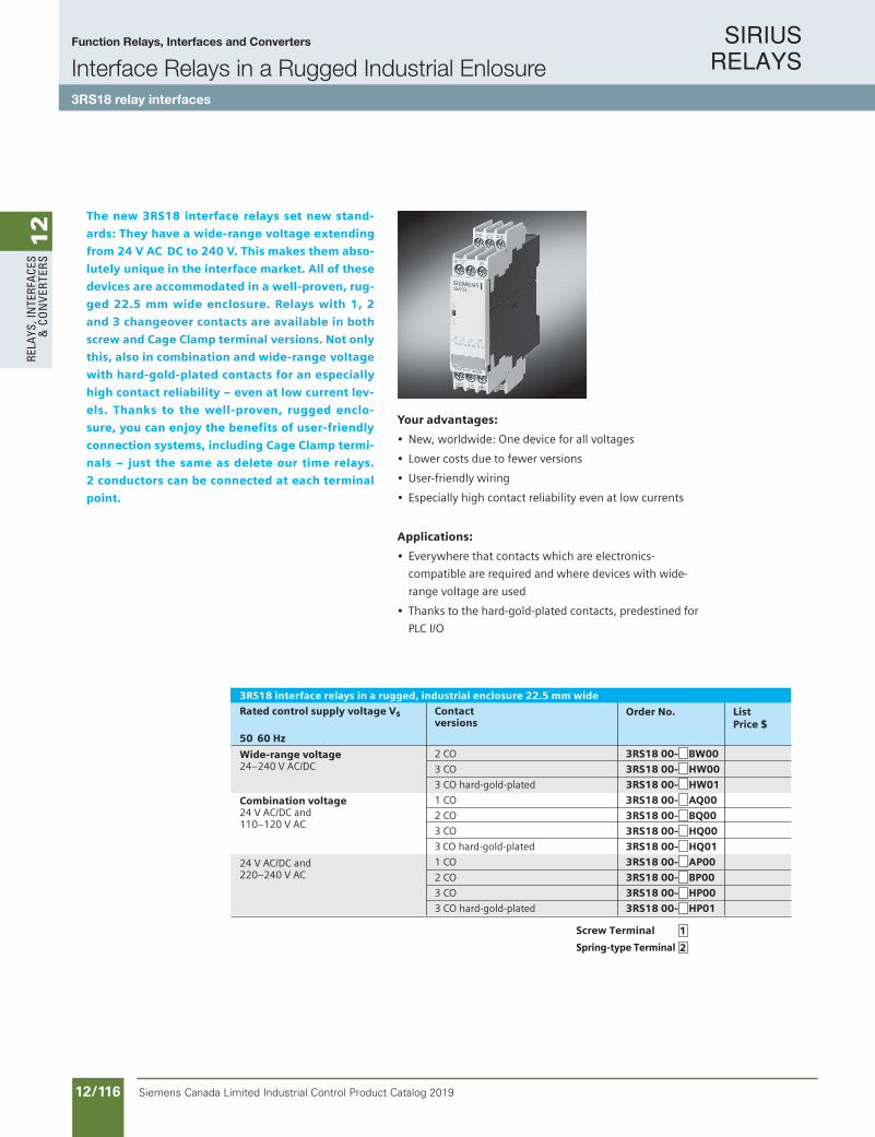
SIRIUS RELAYS
Siemens Canada Limited Industrial Control Product Catalog 201912/116
12
RELA
YS, I
NTE
RFA
CES
& C
ON
VERT
ERS
Siemens / Industrial Controls Previous folio: IC10 11/67
Wide-range voltage24–240 V AC/DC
Combination voltage24 V AC/DC and110–120 V AC
24 V AC/DC and220–240 V AC
1
2
The new 3RS18 interface relays set new stand-
ards: They have a wide-range voltage extending
from 24 V AC DC to 240 V. This makes them abso-
lutely unique in the interface market. All of these
devices are accommodated in a well-proven, rug-
ged 22.5 mm wide enclosure. Relays with 1, 2
and 3 changeover contacts are available in both
screw and Cage Clamp terminal versions. Not only
this, also in combination and wide-range voltage
with hard-gold-plated contacts for an especially
high contact reliability – even at low current lev-
els. Thanks to the well-proven, rugged enclo-
sure, you can enjoy the benefits of user-friendly
connection systems, including Cage Clamp termi-
nals – just the same as delete our time relays.
2 conductors can be connected at each terminal
point.
Interface Relays in a RuggedIndustrial Enclosure3RS18 relay interfaces
Rated control supply voltage Vs Contactversions
50 60 Hz
2 CO 3RS18 00- BW00
3 CO 3RS18 00- HW00
3 CO hard-gold-plated 3RS18 00- HW01
1 CO 3RS18 00- AQ00
2 CO 3RS18 00- BQ00
3 CO 3RS18 00- HQ00
3 CO hard-gold-plated 3RS18 00- HQ01
1 CO 3RS18 00- AP00
2 CO 3RS18 00- BP00
3 CO 3RS18 00- HP00
3 CO hard-gold-plated 3RS18 00- HP01
Your advantages:
• New, worldwide: One device for all voltages
• Lower costs due to fewer versions
• User-friendly wiring
• Especially high contact reliability even at low currents
Applications:
• Everywhere that contacts which are electronics-
compatible are required and where devices with wide-
range voltage are used
• Thanks to the hard-gold-plated contacts, predestined for
PLC I/O
Order No. ListPrice $
3RS18 interface relays in a rugged, industrial enclosure 22.5 mm wide
Screw Terminal
Spring-type Terminal
Function Relays, Interfaces and Converters
Interface Relays in a Rugged Industrial Enlosure3RS18 relay interfaces

SIRIUS RELAYS
Siemens Canada Limited Industrial Control Product Catalog 2019 12/117
12
RELAYS, IN
TERFACES
& CO
NVERTERS
Siemens / Industrial Controls Previous folio: IC10 11/68
10/188 Siemens IC 10 · 2016
RelaysCoupling Relays and Signal Converters/Interface Converters
SIRIUS 3RS70 signal converters
10
Overview
SIRIUS 3RS70 signal converters
Signal converters perform the coupling function for analog signals on both the input side and the output side. They are indispensable when processing analog values with electronic controls. Under harsh industrial conditions in particular, it is often necessary to transmit analog signals over long distances. Electrical separation is then needed as a result of the different power supplies. The resistance of the wiring causes potential differences and losses which must be prevented.
Electromagnetic disturbance and overvoltages can affect the signals on the input side in particular or even destroy the analog modules. All terminals of the 3RS70 signal converters are safe up to a voltage of 30 V DC and protected against switching poles. Short-circuit protection is an especially important function for the outputs.
The devices are EMC-tested according to• IEC 61000-6-4 (basic standard for emitted interference)• IEC 61000-6-2 (basic standard for interference immunity)
The analog signals comply with • IEC 60381-1/2.
Note:
For the conversion tool e.g. from 3RS17 to 3RS70, seewww.siemens.com/sirius/conversion-tool.
Article No. scheme
Note:
The Article No. scheme is presented here merely for information purposes and for better understanding of the logic behind the article numbers.
For your orders, please use the article numbers quoted in the catalog in the Selection and ordering data.
Benefits
• Narrow width• Easy-to-set universal converters• Converters with frequency output• All ranges are fully calibrated
• Universal family of devices – the perfect solution for every application
• Integrated manual/automatic switch with a setpoint generator• Outputs are short-circuit-proof• Up to 30 V – protected against damage caused by wiring
errors
Application
Signal converters are used in analog signal processing for• Electrical separation• Conversion of normalized and non-normalized signals• Amplification and impedance adaptation• Conversion to a frequency for processing by a digital input• Overvoltage and EMC protection• Short-circuit protection of the outputs
Digit of the Article No. 1st - 5th
@@@@@6th
@7th
@ –8th
@9th
@10th
@11th
012th
0
Signal converters 3RS70
Type of input signal @ @Connection methods @Type of output signal @Version of the supply voltage @Example 3RS70 0 0 – 1 A E 0 0
IC10_10_14.fm Page 188 Tuesday, June 14, 2016 12:21 PM
Function Relays, Interfaces and Converters
Signal Converters3RS70

SIRIUS RELAYS
Siemens Canada Limited Industrial Control Product Catalog 201912/118
12
RELA
YS, I
NTE
RFA
CES
& C
ON
VERT
ERS
Siemens / Industrial Controls Previous folio: IC10 11/69
10/189Siemens IC 10 · 2016
RelaysCoupling Relays and Signal Converters/Interface Converters
SIRIUS 3RS70 signal converters
10
3RS7025 manual/automatic converterFor special applications in which analog signals have to be sim-ulated, or during plant commissioning when the actual process value is not yet available, the 3RS7025 devices feature an ad-justable potentiometer for manual setpoint selection and a manual/automatic switch.
The potentiometer for the 3RS7025 devices is used to simulate analog output signals when the changeover switch is set to "Manual" and the control supply voltage is applied, without the
need for an analog input signal. The scale ranges from0 ... 100 %.
Example: When it is set for an output of 4 ... 20 mA, the left stop on the potentiometer represents an output current of 4 mA and the right stop represents an output current of 20 mA. In the "Auto" switch position, the output signal follows the input signal propor-tionally regardless of the potentiometer setting.
3RS70 interface converters, application example: analog signal processing
Technical specifications
Single-range converters, active/passive
IC01_00425a
Sensor/analog value generator
3RS70 converter Electronic control
OutputInput
3RS70 converter Actuator with analog input
0 ... 10 V0/4 ... 20 mA
0 ... 10 V0/4 ... 20 mA0 ... 10 kHz
0 ... 10 V0/4 ... 20 mA
0 ... 10 V0/4 ... 20 mA
epyT 3RS7000-.AE00 3RS7000-.CE00,3RS7000-.DE00
3RS7002-.AE00,3RS7003-.AE00
3RS7002-.CE00,3RS7002-.DE00,3RS7003-.CE00,3RS7003-.DE00
3RS7020-.ET00
General data
Dimensions (W x H x D) mm 6.2 × 93 × 73 6.2 × 93 × 71
Ambient temperature C°noitarepo gniruD• -25 ... +60C°egarots gniruD• -40 ... +85
Relative humidity during operation % 10 ... 90
Insulation voltageFor overvoltage category III To IEC 60664 for pollution degree 3 Rated value
V 50
Active power input W 0.29 --
Degree of protection IP20
Conductor cross-sections
Screw terminals
²mmdiloS• 1x (0.25 ... 2.5)²mmeveels dne htiw dednarts yleniF• 1x (0.25 ... 1.5)GWAdilos ,selbac GWA• 1x (20 ... 14)
Spring-type terminals
²mmdiloS• 1x (0.25 ... 2.5)²mmeveels dne tuohtiw dednarts yleniF• 1x (0.25 ... 2.5)²mmeveels dne htiw dednarts yleniF• 1x (0.25 ... 1.5)GWAdilos ,selbac GWA• 1x (20 ... 14)
Inputs
Input voltage V.xaM• 30VlacipyT• 24
Input impedance • Of current input Ω -- 100
ktupni egatlov fO• Ω 330 --
Outputs
Load • Maximum at current output Ω 500 1000
ktuptuo egatlov ta mumixaM• Ω 2 -- 2 --
Relative measuring accuracy % 0.1
Overvoltage strengthMaximum at current output
V 30
Short-circuit proof Yes
W
H
D
IC10_10_14.fm Page 189 Tuesday, June 14, 2016 12:21 PM
Function Relays, Interfaces and Converters
Signal Converters3RS70
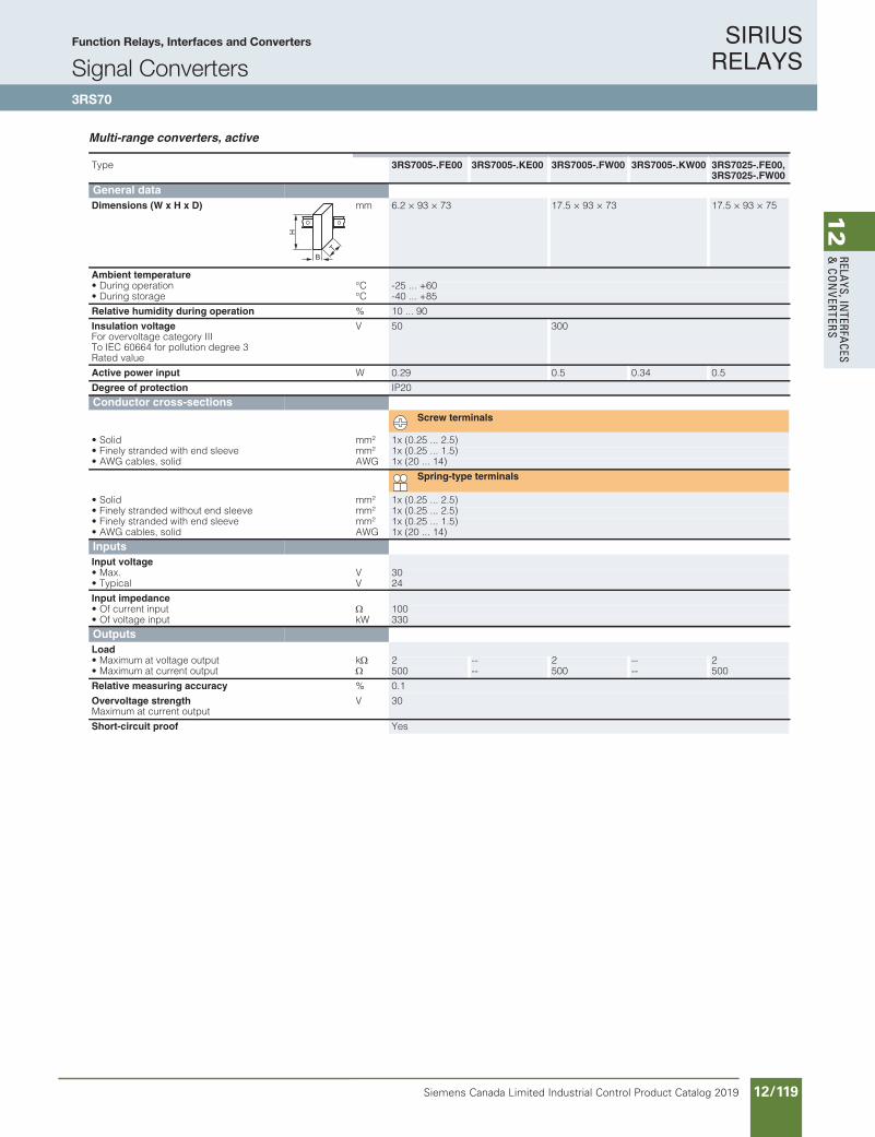
SIRIUS RELAYS
Siemens Canada Limited Industrial Control Product Catalog 2019 12/119
12
RELAYS, IN
TERFACES
& CO
NVERTERS
Siemens / Industrial Controls Previous folio: IC10 11/65
10/190 Siemens IC 10 · 2016
RelaysCoupling Relays and Signal Converters/Interface Converters
SIRIUS 3RS70 signal converters
10
Multi-range converters, active
Type 3RS7005-.FE00 3RS7005-.KE00 3RS7005-.FW00 3RS7005-.KW00 3RS7025-.FE00,3RS7025-.FW00
General data
Dimensions (W x H x D) mm 6.2 × 93 × 73 17.5 × 93 × 73 17.5 × 93 × 75
Ambient temperature • During operation °C -25 ... +60• During storage °C -40 ... +85
Relative humidity during operation % 10 ... 90
Insulation voltageFor overvoltage category III To IEC 60664 for pollution degree 3 Rated value
V 50 300
Active power input W 0.29 0.5 0.34 0.5
Degree of protection IP20
Conductor cross-sections
Screw terminals
• Solid mm² 1x (0.25 ... 2.5)• Finely stranded with end sleeve mm² 1x (0.25 ... 1.5)• AWG cables, solid AWG 1x (20 ... 14)
Spring-type terminals
• Solid mm² 1x (0.25 ... 2.5)• Finely stranded without end sleeve mm² 1x (0.25 ... 2.5)• Finely stranded with end sleeve mm² 1x (0.25 ... 1.5)• AWG cables, solid AWG 1x (20 ... 14)
Inputs
Input voltage • Max. V 30• Typical V 24
Input impedance • Of current input 100• Of voltage input kW 330
Outputs
Load • Maximum at voltage output k 2 -- 2 -- 2• Maximum at current output 500 -- 500 -- 500
Relative measuring accuracy % 0.1
Overvoltage strengthMaximum at current output
V 30
Short-circuit proof Yes
B
H
T
IC10_10_14.fm Page 190 Tuesday, June 14, 2016 12:21 PM
Function Relays, Interfaces and Converters
Signal Converters3RS70
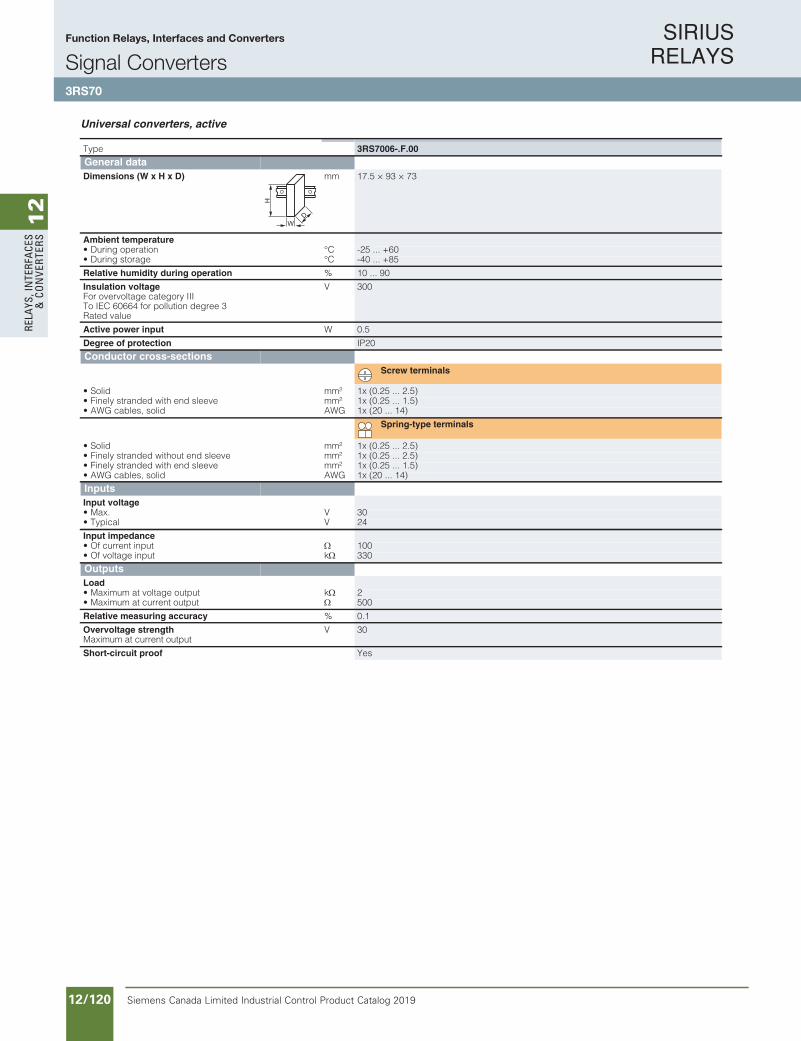
SIRIUS RELAYS
Siemens Canada Limited Industrial Control Product Catalog 201912/120
12
RELA
YS, I
NTE
RFA
CES
& C
ON
VERT
ERS
Siemens / Industrial Controls Previous folio: IC10 11/70
10/191Siemens IC 10 · 2016
RelaysCoupling Relays and Signal Converters/Interface Converters
SIRIUS 3RS70 signal converters
10
Universal converters, active
Type 3RS7006-.F.00
General data
Dimensions (W x H x D) mm 17.5 × 93 × 73
Ambient temperature • During operation °C -25 ... +60• During storage °C -40 ... +85
Relative humidity during operation % 10 ... 90
Insulation voltageFor overvoltage category III To IEC 60664 for pollution degree 3 Rated value
V 300
Active power input W 0.5
Degree of protection IP20
Conductor cross-sections
Screw terminals
• Solid mm² 1x (0.25 ... 2.5)• Finely stranded with end sleeve mm² 1x (0.25 ... 1.5)• AWG cables, solid AWG 1x (20 ... 14)
Spring-type terminals
• Solid mm² 1x (0.25 ... 2.5)• Finely stranded without end sleeve mm² 1x (0.25 ... 2.5)• Finely stranded with end sleeve mm² 1x (0.25 ... 1.5)• AWG cables, solid AWG 1x (20 ... 14)
Inputs
Input voltage • Max. V 30• Typical V 24
Input impedance • Of current input 100• Of voltage input k 330
Outputs
Load • Maximum at voltage output k 2• Maximum at current output 500
Relative measuring accuracy % 0.1
Overvoltage strengthMaximum at current output
V 30
Short-circuit proof Yes
W
H
D
IC10_10_14.fm Page 191 Tuesday, June 14, 2016 12:21 PM
Function Relays, Interfaces and Converters
Signal Converters3RS70
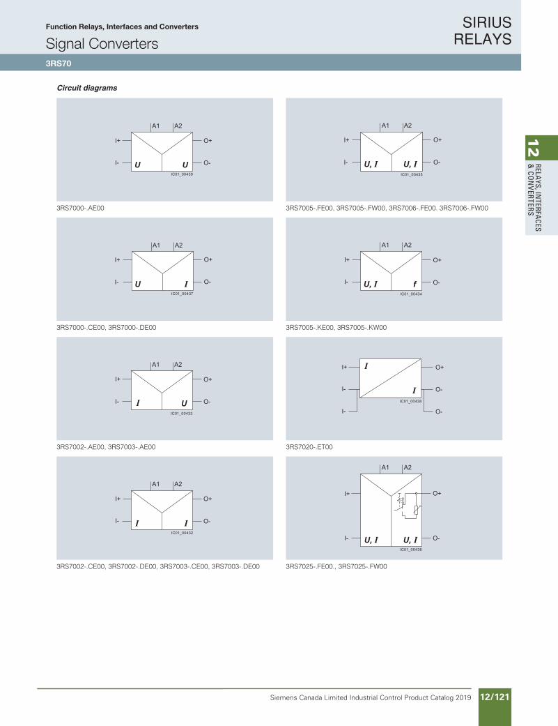
SIRIUS RELAYS
Siemens Canada Limited Industrial Control Product Catalog 2019 12/121
12
RELAYS, IN
TERFACES
& CO
NVERTERS
Siemens / Industrial Controls Previous folio: IC10 11/71
10/192 Siemens IC 10 · 2016
RelaysCoupling Relays and Signal Converters/Interface Converters
SIRIUS 3RS70 signal converters
10
Circuit diagrams
3RS7000-.AE00
3RS7000-.CE00, 3RS7000-.DE00
3RS7002-.AE00, 3RS7003-.AE00
3RS7002-.CE00, 3RS7002-.DE00, 3RS7003-.CE00, 3RS7003-.DE00
3RS7005-.FE00, 3RS7005-.FW00, 3RS7006-.FE00. 3RS7006-.FW00
3RS7005-.KE00, 3RS7005-.KW00
3RS7020-.ET00
3RS7025-.FE00., 3RS7025-.FW00
I-
I+
O-
O+
A1 A2
IC01_00439
I-
I+
O-
O+
A1 A2
IC01_00437
I-
I+
O-
O+
A1 A2
IC01_00433
A1
O-I-
O+I+
A2
IC01_00432
I-
I+
O-
O+
A1 A2
IC01_00435
I-
I+
O-
O+
A1 A2
IC01_00434
I- O-
I-
I+
O-
O+
IC01_00438
I-
I+
O-
O+
A1 A2
HA0
IC01_00436
IC10_10_14.fm Page 192 Tuesday, June 14, 2016 12:21 PM
Function Relays, Interfaces and Converters
Signal Converters3RS70
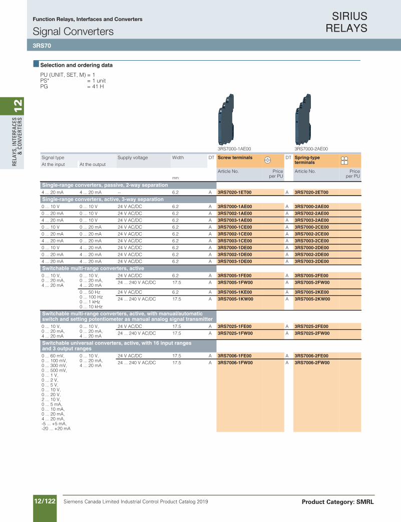
SIRIUS RELAYS
Siemens Canada Limited Industrial Control Product Catalog 201912/122
12
RELA
YS, I
NTE
RFA
CES
& C
ON
VERT
ERS
Siemens / Industrial Controls Previous folio: IC10 11/72
10/193Siemens IC 10 · 2016* You can order this quantity or a multiple thereof.Illustrations are approximate
RelaysCoupling Relays and Signal Converters/Interface Converters
SIRIUS 3RS70 signal converters
10
Selection and ordering data
PU (UNIT, SET, M) = 1PS* = 1 unitPG = 41 H
3RS7000-1AE00 3RS7000-2AE00
Signal type Supply voltage Width DT Screw terminals DT Spring-typeterminalsAt the input At the output
Article No. Priceper PU
Article No. Priceper PUmm
Single-range converters, passive, 2-way separation4 ... 20 mA 4 ... 20 mA -- 6.2 A 3RS7020-1ET00 A 3RS7020-2ET00
Single-range converters, active, 3-way separation0 ... 10 V 0 ... 10 V 24 V AC/DC 6.2 A 3RS7000-1AE00 A 3RS7000-2AE00
0 ... 20 mA 0 ... 10 V 24 V AC/DC 6.2 A 3RS7002-1AE00 A 3RS7002-2AE00
4 ... 20 mA 0 ... 10 V 24 V AC/DC 6.2 A 3RS7003-1AE00 A 3RS7003-2AE00
0 ... 10 V 0 ... 20 mA 24 V AC/DC 6.2 A 3RS7000-1CE00 A 3RS7000-2CE00
0 ... 20 mA 0 ... 20 mA 24 V AC/DC 6.2 A 3RS7002-1CE00 A 3RS7002-2CE00
4 ... 20 mA 0 ... 20 mA 24 V AC/DC 6.2 A 3RS7003-1CE00 A 3RS7003-2CE00
0 ... 10 V 4 ... 20 mA 24 V AC/DC 6.2 A 3RS7000-1DE00 A 3RS7000-2DE00
0 ... 20 mA 4 ... 20 mA 24 V AC/DC 6.2 A 3RS7002-1DE00 A 3RS7002-2DE00
4 ... 20 mA 4 ... 20 mA 24 V AC/DC 6.2 A 3RS7003-1DE00 A 3RS7003-2DE00
Switchable multi-range converters, active0 ... 10 V,0 ... 20 mA,4 ... 20 mA
0 ... 10 V,0 ... 20 mA,4 ... 20 mA
24 V AC/DC 6.2 A 3RS7005-1FE00 A 3RS7005-2FE00
24 ... 240 V AC/DC 17.5 A 3RS7005-1FW00 A 3RS7005-2FW00
0 ... 50 Hz0 ... 100 Hz0 ... 1 kHz0 ... 10 kHz
24 V AC/DC 6.2 A 3RS7005-1KE00 A 3RS7005-2KE00
24 ... 240 V AC/DC 17.5 A 3RS7005-1KW00 A 3RS7005-2KW00
Switchable multi-range converters, active, with manual/automaticswitch and setting potentiometer as manual analog signal transmitter0 ... 10 V,0 ... 20 mA,4 ... 20 mA
0 ... 10 V,0 ... 20 mA,4 ... 20 mA
24 V AC/DC 17.5 A 3RS7025-1FE00 A 3RS7025-2FE00
24 ... 240 V AC/DC 17.5 A 3RS7025-1FW00 A 3RS7025-2FW00
Switchable universal converters, active, with 16 input rangesand 3 output ranges0 ... 60 mV,0 ... 100 mV,0 ... 300 mV,0 ... 500 mV,0 ... 1 V,0 ... 2 V,0 ... 5 V,0 ... 10 V,0 ... 20 V,2 ... 10 V,0 ... 5 mA,0 ... 10 mA,0 ... 20 mA,4 ... 20 mA,-5 ... +5 mA,-20 ... +20 mA
0 ... 10 V,0 ... 20 mA,4 ... 20 mA
24 V AC/DC 17.5 A 3RS7006-1FE00 A 3RS7006-2FE00
24 ... 240 V AC/DC 17.5 A 3RS7006-1FW00 A 3RS7006-2FW00
IC10_10_14.fm Page 193 Tuesday, June 14, 2016 12:21 PM
Function Relays, Interfaces and Converters
Signal Converters3RS70
Product Category: SMRL

SIRIUS RELAYS
Siemens Canada Limited Industrial Control Product Catalog 2019 12/123
12
RELAYS, IN
TERFACES
& CO
NVERTERS
Siemens / Industrial Controls Previous folio: IC10 11/73
10/194 Siemens IC 10 · 2016* You can order this quantity or a multiple thereof.
Illustrations are approximate
RelaysCoupling Relays and Signal Converters/Interface Converters
SIRIUS 3RS70 signal converters
10
Accessories
Version DT Article No. Priceper PU
PU(UNIT,
SET,M)
PS* PG
Galvanic isolation plates
3RQ3900-0A
Galvanic isolation plates
For electrical separation of different potentials when devices of different types are installed side by side
A 3RQ3900-0A 1 10 units 41H
Connecting combs
3RQ3901-0B
Connecting combs
For linking the same potentials, current carrying capacity for infeed max. 6 A
• 2-pole A 3RQ3901-0A 1 10 units 41H
• 4-pole A 3RQ3901-0B 1 10 units 41H
• 8-pole A 3RQ3901-0C 1 10 units 41H
• 16-pole A 3RQ3901-0D 1 10 units 41H
Clip-on labelsClip-on labels
For terminal marking and equipment labeling, white
• 5 x 5 mm A 3RQ3902-0A 100 2 000 units 41H
Tools for opening spring-type terminals
3RA2908-1A
Spring-typeterminals
ScrewdriversFor all SIRIUS devices with spring-type terminals; 3.0 mm x 0.5 mm; length approx. 200 mm, titanium gray/black, partially insulated
A 3RA2908-1A 1 1 unit 41B
IC10_10_14.fm Page 194 Tuesday, June 14, 2016 12:21 PM
Function Relays, Interfaces and Converters
Signal Converters3RS70
Product Category: SMRL
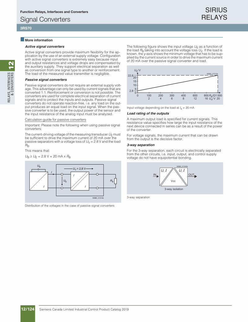
SIRIUS RELAYS
Siemens Canada Limited Industrial Control Product Catalog 201912/124
12
RELA
YS, I
NTE
RFA
CES
& C
ON
VERT
ERS
Siemens / Industrial Controls Previous folio: IC10 11/74
10/195Siemens IC 10 · 2016
RelaysCoupling Relays and Signal Converters/Interface Converters
SIRIUS 3RS70 signal converters
10
More information
Active signal converters
Active signal converters provide maximum flexibility for the ap-plication by the use of an external supply voltage. Configuration with active signal converters is extremely easy because input and output resistances and voltage drops are compensated by the auxiliary supply. They support electrical separation as well as conversion from one signal type to another or reinforcement. The load of the measured value transmitter is negligible.
Passive signal converters
Passive signal converters do not require an external supply volt-age. This advantage can only be used by current signals that are converted 1:1. Reinforcement or conversion is not possible. The converters are used for complete electrical separation of current signals and to protect the inputs and outputs. Passive signal converters do not operate reaction-free, i.e. any load on the out-put produces an equal load on the input signal. When the pas-sive converter is to be used, the output power of the sensor and the input resistance of the analog input must be analyzed.
Calculation guide for passive converters
Important: Please note the following when using passive signal converters:
The current-driving voltage of the measuring transducer UE must be sufficient to drive the maximum current of 20 mA over the passive separators with a voltage loss of UV = 2.8 V and the load RB.
This means that:
UB UE = 2.8 V + 20 mA x RB
Distribution of the voltages in the case of passive signal converters
The following figure shows the input voltage UE as a function of the load RB taking into account the voltage loss UV. If the load is known, the y-axis shows the minimum voltage that has to be sup-plied by the current source in order to drive the maximum current of 20 mA over the passive signal converter and load.
Input voltage depending on the load at Ia = 20 mA
Load rating of the outputs
A maximum output load is specified for current signals. This resistance value specifies how large the input resistance of the next device connected in series can be as a result of the power of the converter.
For voltage signals, the maximum current that can be drawn from the output is the decisive factor.
3-way separation
For the 3-way separation, each circuit is electrically separated from the other circuits, i.e. input, output, and control supply voltage do not have equipotential bonding.
3-way separation
NSB0_01312b
UB
UE RB
UV = 2,8 V
NSB0_01313b
RB/ΩUA/ V12 201684 62
600 1 000400200 300100 800
UE/ V
2022,8
0
1510
50
2,8
OUTIN
3-way isolation
NSB0_01343b
Vcc
IC10_10_14.fm Page 195 Tuesday, June 14, 2016 12:21 PM
Function Relays, Interfaces and Converters
Signal Converters3RS70
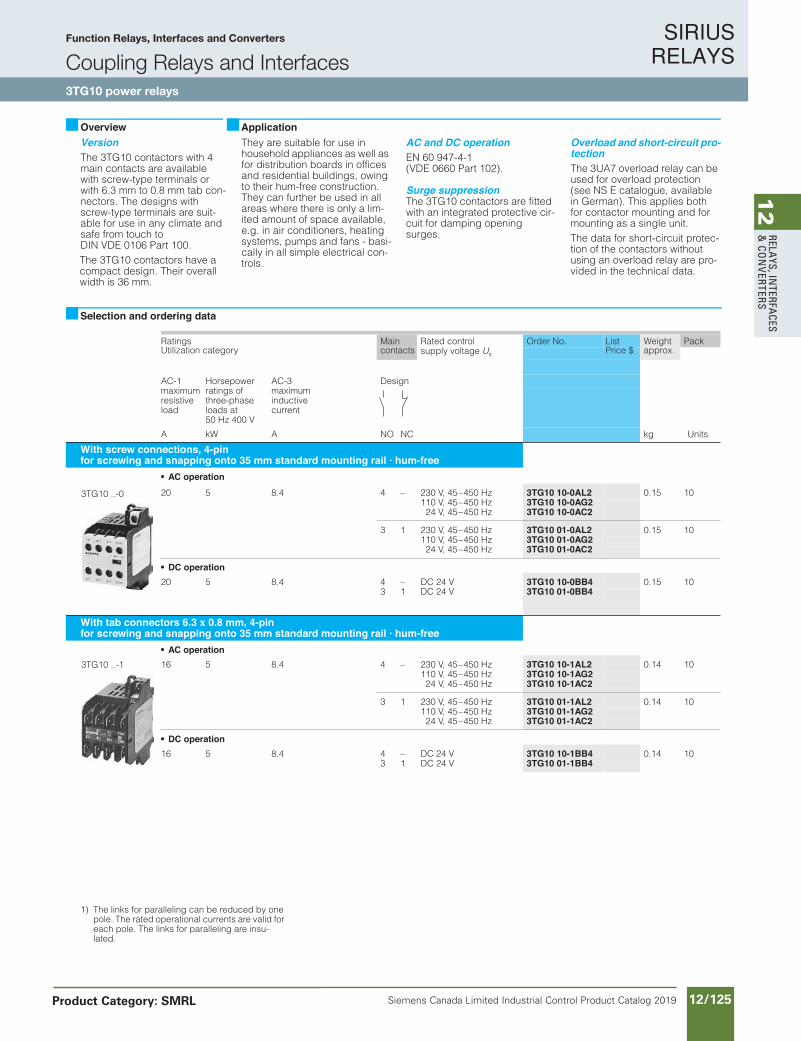
SIRIUS RELAYS
Siemens Canada Limited Industrial Control Product Catalog 2019 12/125
12
RELAYS, IN
TERFACES
& CO
NVERTERS
Siemens / Industrial Controls Previous folio: IC10 11/75
VersionThe 3TG10 contactors with 4 main contacts are available with screw-type terminals or with 6.3 mm to 0.8 mm tab con-nectors. The designs with screw-type terminals are suit-able for use in any climate and safe from touch to DIN VDE 0106 Part 100.The 3TG10 contactors have a compact design. Their overall width is 36 mm.
They are suitable for use in household appliances as well as for distribution boards in offices and residential buildings, owing to their hum-free construction. They can further be used in all areas where there is only a lim-ited amount of space available, e.g. in air conditioners, heating systems, pumps and fans - basi-cally in all simple electrical con-trols.
AC and DC operationEN 60 947-4-1 (VDE 0660 Part 102).
Surge suppressionThe 3TG10 contactors are fitted with an integrated protective cir-cuit for damping opening surges.
Overload and short-circuit pro-tectionThe 3UA7 overload relay can be used for overload protection (see NS E catalogue, available in German). This applies both for contactor mounting and for mounting as a single unit. The data for short-circuit protec-tion of the contactors without using an overload relay are pro-vided in the technical data.
Ratings Main Rated controlsupply voltage Us
Order No. Weight PackUtilization category contacts approx.
AC-1maximumresistiveload
Horsepowerratings of three-phase loads at50 Hz 400 V
AC-3maximuminductivecurrent
Design
CNONAWkA kg Units
With screw connections, 4-pinfor screwing and snapping onto 35 mm standard mounting rail · hum-free
AC operation
zH 054–54 ,V 032–44.8502 3TG10 10-0AL2 0.15 10110 V, 45–450 Hz 3TG10 10-0AG224 V, 45–450 Hz 3TG10 10-0AC2
3 1 230 V, 45–450 Hz 3TG10 01-0AL2 0.15 10110 V, 45–450 Hz 3TG10 01-0AG224 V, 45–450 Hz 3TG10 01-0AC2
DC operationV 42 CD–44.8502 3TG10 10-0BB4 0.15 10
3 1 DC 24 V 3TG10 01-0BB4
With tab connectors 6.3 x 0.8 mm, 4-pinfor screwing and snapping onto 35 mm standard mounting rail · hum-free
AC operationzH 054–54 ,V 032–44.8561 3TG10 10-1AL2 0.14 10
110 V, 45–450 Hz 3TG10 10-1AG224 V, 45–450 Hz 3TG10 10-1AC2
3 1 230 V, 45–450 Hz 3TG10 01-1AL2 0.14 10110 V, 45–450 Hz 3TG10 01-1AG224 V, 45–450 Hz 3TG10 01-1AC2
DC operationV 42 CD–44.8561 3TG10 10-1BB4 0.14 10
3 1 DC 24 V 3TG10 01-1BB4
Overview Application
Selection and ordering data
3TG10 ..-0
3TG10 ..-1
1) The links for paralleling can be reduced by one pole. The rated operational currents are valid for each pole. The links for paralleling are insu-lated.
ListPrice $
Function Relays, Interfaces and Converters
Coupling Relays and Interfaces3TG10 power relays
Product Category: SMRL
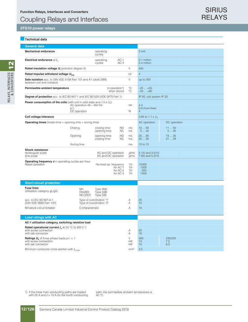
SIRIUS RELAYS
Siemens Canada Limited Industrial Control Product Catalog 201912/126
12
RELA
YS, I
NTE
RFA
CES
& C
ON
VERT
ERS
Siemens / Industrial Controls Previous folio: IC10 11/76
General dataMechanical endurance operating
cycles3 mill.
Electrical endurance at Ie operating cycles
AC-1AC-3
0.1 million0.4 million
Rated insulation voltage Ui V)3 eerged noitullop( 400
Rated impulse withstand voltage Uimp kV 4
Safe isolation acc. to DIN VDE 0106 Part 101 and A1 (draft 2/89)between coil and contacts
V up to 300
Permissible ambient temperature in operation1)when stored
°C°C
–25 ... +55 –50 ... +80
Degree of protection acc. to IEC 60 947-1 and IEC 60 529 (VDE 0470 Part 1) IP 00, coil system IP 20
Power consumption of the coils (with coil in cold state and 1.0 x Us)AC operation 45 – 450 Hzp.f.DC operation
VA
W
4.40.9 (hum-free)4
Coil voltage tolerance 0.85 to 1.1 x Us
Operating times (break-time = opening time + arcing time) AC operation DC operation
Closing closing timeopening time
NONC
msms
10 ... 50 5 ... 45
11 ... 50 5 ... 45
Opening opening timeclosing time
NONC
msms
20 ... 30 20 ... 30
19 ... 35 21 ... 39
smemit gnicrA 10 to 15
Shock resistancenoitarepo CD dna CAeslup ralugnatcer g/ms 5.1/5 and 3.5/10 noitarepo CD dna CAeslup enis g/ms 7.9/5 and 5.2/10
Operating frequency z in operating cycles per hourycneuqerf .po daol-oNnoitarepo detaR
for AC-1for AC-2for AC-3
1/h1/h1/h1/h
10000 1000 500
1000
Short-circuit protectionFuse linksUtilisation category gL/gG
NH Type 3NADIAZEDNEOZED
Type 5SBType 5SE
acc. to IEC 60 947-4-1 Type of coordination "1"(DIN VDE 0660 Part 102) Type of coordination "2"
AA
2510
Miniature circuit-brea Acitsiretcarahc-Crek 10
Load ratings with ACAC-1 utilisation category, switching resistive load
Rated operational current Ie at 55 °C to 400 V 1)with screw connectionwith tab connector
AA
2016
Ratings Ue V1 = .f.p sdaol esahp-eerht fo 400 230/220with screw connectionwith tab connector
kWkW
1310
7.56.0
Minimum conductor cross-section with Ie load mm2 2.5
Technical data
1) If the three main conducting paths are loaded with 20 A and I > 10 A for the fourth conducting
path: the permissible ambient temperature is 40 °C.
Function Relays, Interfaces and Converters
Coupling Relays and Interfaces3TG10 power relays
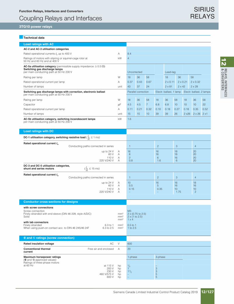
SIRIUS RELAYS
Siemens Canada Limited Industrial Control Product Catalog 2019 12/127
12
RELAYS, IN
TERFACES
& CO
NVERTERS
Siemens / Industrial Controls Previous folio: IC10 11/77
Function Relays, Interfaces and Converters
3TG10 power relays
SIMIREL
Load ratings with ACAC-2 and AC-3 utilisation categories
Rated operational currents Ie up to 400 V A 8.4
Ratings of motors with slipring or squirrel-cage rotor at 50 Hz and 60 Hz and at 400 V
kW 4
AC-5a utilisation category (permissible supply impedance: 0.5Switching gas discharge lampsper main conducting path at 50 Hz 230 V Uncorrected Lead-lag
Rating per lamp W 18 36 58 18 36 58
Rated operational current per lamp A 0.37 0.43 0.67 2 x 0.11 2 x 0.21 2 x 0.32
Number of lamps unit 43 37 24 2 x 81 2 x 42 2 x 28
Switching gas discharge lamps with correction, electronic ballastper main conducting path at 50 Hz 230 V
Parallel correction Electr. ballast, 1 lamp Electr. ballast, 2 lamps
Rating per lamp W 18 36 58 18 36 58 18 36 58
Capacitor F 4.5 4.5 7 6.8 6.8 10 10 10 22
Rated operational current per lamp A 0.11 0.21 0.32 0.10 0.18 0.27 0.18 0.35 0.52
Number of lamps unit 15 15 10 39 39 26 2 x26 2 x 26 2 x1
AC-5b utilisation category, switching incandescent lampsper main conducting path at 50 Hz 230 V
kW 1.6
Load ratings with DC
DC-1 utilisation category, switching resistive load ( 1 ms)
Rated operational current IeConducting paths connected in series 1 2 3 4
up to 24 V60 V
AA
166
1616
1818
2020
110 V220 V/240 V
AA
20.8
61.6
166
2020
DC-3 and DC-5 utilisation categories,shunt and series motors ( 15 ms)
Rated operational current IeConducting paths connected in series 1 2 3 4
up to 24 V60 V
AA
100.5
165
1616
1816
110 V220 V/240 V
AA
0.15–
0.35–
101.75
102
Conductor cross-sections for designs
with screw connectionsScrew connectionFinely stranded with end sleeve (DIN 46 228, style A/D/C)Solid
mm2
mm2
mm2
M32 x (0.75 to 2.5) 2 x (1 to 2.5) 1 x 4
with tab connectorsFinely strandedWhen using push-on contact acc. to DIN 46 245/46 247
6.3 to 16.3 to 2.5
mm2
mm20.5 to 1 1 to 2.5
s and u ratings (screw connection)
Rated insulation voltage AC V 600
Conventional thermal current
Free air and enclosed A 20
Maximum horsepower ratings(s and u-approved values)Ratings of three-phase motors at 60 Hz
1-phase 3-phase
at 115 V200 V230 V
460 V/575 V600 V
hphphphphp
1/2111/2––
–3355
Technical data
LR----
LR----
Function Relays, Interfaces and Converters
Coupling Relays and Interfaces3TG10 power relays
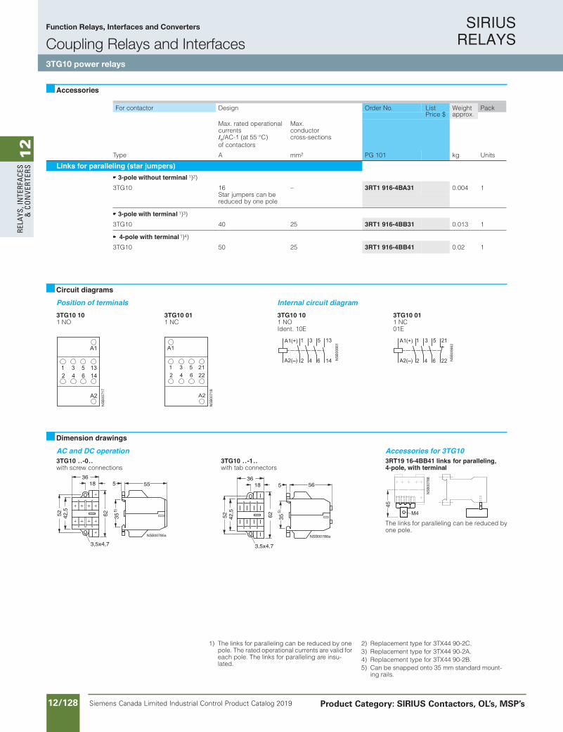
SIRIUS RELAYS
Siemens Canada Limited Industrial Control Product Catalog 201912/128
12
RELA
YS, I
NTE
RFA
CES
& C
ON
VERT
ERS
Siemens / Industrial Controls Previous folio: IC10 11/78
Function Relays, Interfaces and Converters
3TG10 power relays
SIMIREL
For contactor Design Order No. Weight Packapprox.
Max. rated operational currentsIe/AC-1 (at 55 °C)of contactors
Max.conductorcross-sections
Type A mm2 PG 101 kg Units
Links for paralleling (star jumpers)3-pole without terminal 1)2)
3TG10 16Star jumpers can be reduced by one pole
– 3RT1 916-4BA31 0.004 1
3-pole with terminal 1)3)
3TG10 40 25 3RT1 916-4BB31 0.013 1
4-pole with terminal 1)4)
3TG10 50 25 3RT1 916-4BB41 0.02 1
Position of terminals Internal circuit diagram3TG10 101 NO
3TG10 011 NC
3TG10 101 NO Ident. 10E
3TG10 011 NC01E
AC and DC operation Accessories for 3TG103TG10 ..-0..with screw connections
3TG10 ..-1..with tab connectors
3RT19 16-4BB41 links for paralleling,4-pole, with terminal
Accessories
Circuit diagrams
Dimension drawings
1836
6242,552
3,5x4,7NSB00785a
35
555
5)
1836
6242,5
52
3,5x4,7
NSB00786a
35
565
5)
The links for paralleling can be reduced by one pole.
1) The links for paralleling can be reduced by one pole. The rated operational currents are valid for each pole. The links for paralleling are insu-lated.
2) Replacement type for 3TX44 90-2C.3) Replacement type for 3TX44 90-2A.4) Replacement type for 3TX44 90-2B.5) Can be snapped onto 35 mm standard mount-
ing rails.
ListPrice $
Function Relays, Interfaces and Converters
Coupling Relays and Interfaces3TG10 power relays
Product Category: SIRIUS Contactors, OL’s, MSP’s
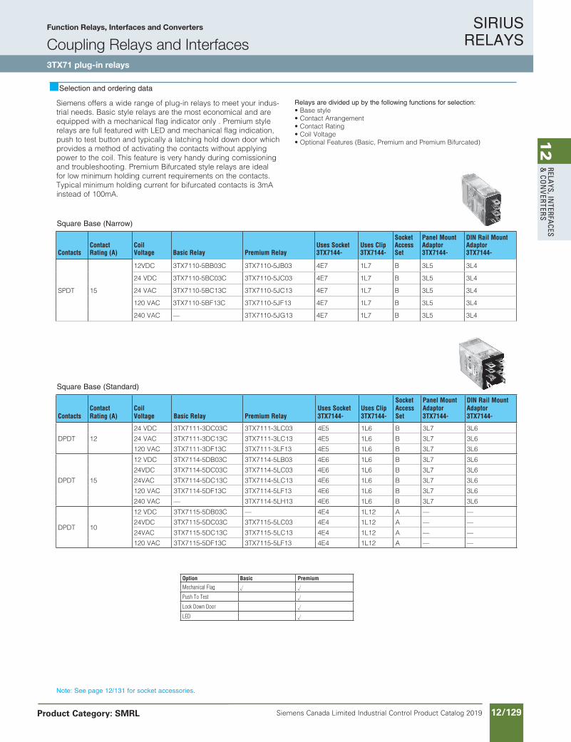
SIRIUS RELAYS
Siemens Canada Limited Industrial Control Product Catalog 2019 12/129
12
RELAYS, IN
TERFACES
& CO
NVERTERS
Siemens offers a wide range of plug-in relays to meet your indus-trial needs. Basic style relays are the most economical and are equipped with a mechanical flag indicator only . Premium style relays are full featured with LED and mechanical flag indication, push to test button and typically a latching hold down door which provides a method of activating the contacts without applying power to the coil. This feature is very handy during comissioning and troubleshooting. Premium Bifurcated style relays are ideal for low minimum holding current requirements on the contacts. Typical minimum holding current for bifurcated contacts is 3mA instead of 100mA.
Relays are divided up by the following functions for selection:• Base style• Contact Arrangement• Contact Rating• Coil Voltage• Optional Features (Basic, Premium and Premium Bifurcated)
Siemens / Industrial Controls Previous folio: IC10 11/79
Selection and ordering data
Square Base (Narrow)
ContactsContact Rating (A)
Coil Voltage Basic Relay Premium Relay
Uses Socket 3TX7144-
Uses Clip 3TX7144-
Socket Access Set
Panel Mount Adaptor 3TX7144-
DIN Rail Mount Adaptor 3TX7144-
SPDT 15
12VDC 3TX7110-5BB03C 3TX7110-5JB03 4E7 1L7 B 3L5 3L4
24 VDC 3TX7110-5BC03C 3TX7110-5JC03 4E7 1L7 B 3L5 3L4
24 VAC 3TX7110-5BC13C 3TX7110-5JC13 4E7 1L7 B 3L5 3L4
120 VAC 3TX7110-5BF13C 3TX7110-5JF13 4E7 1L7 B 3L5 3L4
240 VAC — 3TX7110-5JG13 4E7 1L7 B 3L5 3L4
Square Base (Standard)
ContactsContact Rating (A)
Coil Voltage Basic Relay Premium Relay
Uses Socket 3TX7144-
Uses Clip 3TX7144-
Socket Access Set
Panel Mount Adaptor 3TX7144-
DIN Rail Mount Adaptor 3TX7144-
DPDT 12
24 VDC 3TX7111-3DC03C 3TX7111-3LC03 4E5 1L6 B 3L7 3L6
24 VAC 3TX7111-3DC13C 3TX7111-3LC13 4E5 1L6 B 3L7 3L6
120 VAC 3TX7111-3DF13C 3TX7111-3LF13 4E5 1L6 B 3L7 3L6
DPDT 15
12 VDC 3TX7114-5DB03C 3TX7114-5LB03 4E6 1L6 B 3L7 3L6
24VDC 3TX7114-5DC03C 3TX7114-5LC03 4E6 1L6 B 3L7 3L6
24VAC 3TX7114-5DC13C 3TX7114-5LC13 4E6 1L6 B 3L7 3L6
120 VAC 3TX7114-5DF13C 3TX7114-5LF13 4E6 1L6 B 3L7 3L6
240 VAC — 3TX7114-5LH13 4E6 1L6 B 3L7 3L6
DPDT 10
12 VDC 3TX7115-5DB03C — 4E4 1L12 A — —
24VDC 3TX7115-5DC03C 3TX7115-5LC03 4E4 1L12 A — —
24VAC 3TX7115-5DC13C 3TX7115-5LC13 4E4 1L12 A — —
120 VAC 3TX7115-5DF13C 3TX7115-5LF13 4E4 1L12 A — —
Note: See page 12/131 for socket accessories.
Option Basic Premium
Mechanical Flag u u
Push To Test u
Lock Down Door u
LED u
Function Relays, Interfaces and Converters
Coupling Relays and Interfaces3TX71 plug-in relays
Product Category: SMRL

SIRIUS RELAYS
Siemens Canada Limited Industrial Control Product Catalog 201912/130
12
RELA
YS, I
NTE
RFA
CES
& C
ON
VERT
ERS
Siemens / Industrial Controls Previous folio: IC10 11/80
Square Base (Standard)
ContactsContact Rating (A)
Coil Voltage Basic Relay Premium Relay
Premium Bifurcated
Uses Socket 3TX7144-
Uses Clip 3TX7144-
Socket Access Set
Panel Mount Adaptor 3TX7144-
DIN Rail Mount Adaptor 3TX7144-
3PDT 15
24VDC 3TX7116-5FC03C 3TX7116-5NC03 — 4E8 1L9 A 1M3 1M4
24VAC 3TX7116-5FC13C 3TX7116-5NC13 — 4E8 1L9 A 1M3 1M4
120 VAC 3TX7116-5FF13C 3TX7116-5NF13 — 4E8 1L9 A 1M3 1M4
3PDT 10 24VDC — 3TX7115-5NC03 — 4E4 1L12 A — —
120 VAC 3TX7115-5FF13C 3TX7115-5NF13 — 4E4 1L12 A — —
4PDT
6A for Basic and Premium and 3A for Bifurcated
24VDC 3TX7111-3HC03C 3TX7111-3PC03 3TX7111-5PC03B 4E5 1L6 B 3L7 3L6
24VAC 3TX7111-3HC13C 3TX7111-3PC13 — 4E5 1L6 B 3L7 3L6
120 VAC 3TX7111-3HF13C 3TX7111-3PF13 3TX7111-5PF13B 4E5 1L6 B 3L7 3L6
240 VAC — 3TX7111-3PG13 — 4E5 1L6 B 3L7 3L6
4PDT 15
24VDC 3TX7117-5HC03C 3TX7117-5PC03 — 4E9 1L10 A 1M5 1M6
24VAC 3TX7117-5HC13C 3TX7117-5PC13 — 4E9 1L10 A 1M5 1M6
120 VAC 3TX7117-5HF13C 3TX7117-5PF13 — 4E9 1L10 A 1M5 1M6
Selection and ordering data
Note: See page 12/131 for socket accessories.
Option Basic Premium Premium Bifurcated
Mechanical Flag u u u
Push To Test u u
Lock Down Door u u
LED u u
Function Relays, Interfaces and Converters
Coupling Relays and Interfaces3TX71 plug-in relays
Product Category: SMRL

SIRIUS RELAYS
Siemens Canada Limited Industrial Control Product Catalog 2019 12/131
12
RELAYS, IN
TERFACES
& CO
NVERTERS
Siemens / Industrial Controls Previous folio: IC10 11/81
Standard Octal Base
ContactsContact Rating (A)
Coil Voltage Basic Relay Premium Relay
Uses Socket 3TX7144-
Uses Clip 3TX7144-
Socket Access Set
DPDT 10
12 VDC 3TX7112-1DB03C 3TX7112-1LB03 4E2 1L14 A
24VDC 3TX7112-1DC03C 3TX7112-1LC03 4E2 1L14 A
24VAC 3TX7112-1DC13C 3TX7112-1LC13 4E2 1L14 A
120 VAC 3TX7112-1DF13C 3TX7112-1LF13 4E2 1L14 A
240 VAC 3TX7112-1DG13C 3TX7112-1LG13 4E2 1L14 A
3PDT 10 24VDC 3TX7112-1FC03C 3TX7112-1NC03 4E3 1L14 A
24VAC 3TX7112-1FC13C 3TX7112-1NC13 4E3 1L14 A
120 VAC 3TX7112-1FF13C 3TX7112-1NF13 4E3 1L14 A
240 VAC — 3TX7112-1NG13 4E3 1L14 A
Selection and ordering data
Hermetically Sealed
ContactsContact Rating (A)
Coil Voltage Basic Relay
Uses Socket 3TX7144-
Uses Clip 3TX7144-
Socket Access Set
DPDT 12 24 VDC 3TX7127-5HC00 4E2 1L12 A
4PDT 3
24VDC 3TX7127-3HC00 4E5 1L11 B
24VAC 3TX7127-3HC10 4E5 1L11 B
120 VAC 3TX7127-3HF10 4E5 1L11 B
4PDT 5
12 VDC 3TX7127-3HB03 4E5 1L11 B
24VDC 3TX7127-3HC03 4E5 1L11 B
120 VAC 3TX7127-3HF13 4E5 1L11 B
Note: See socket accessories above.
Access. Series MOV MOV R/C R/C Diode
24VAC/DC 120VAC/DC 6-24VAC/DC 110-240VAC/DC 6-250VDC
A 3TX7144-H1 3TX7144-H20 3TX7144-H4 3TX7144-H5 3TX7144-H6
B 3TX7144-H9 3TX7144-H17 — — 3TX7144-H12
Socket Accessories
Function Relays, Interfaces and Converters
Coupling Relays and Interfaces3TX71 plug-in relays
Product Category: SMRL
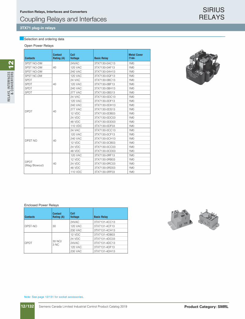
SIRIUS RELAYS
Siemens Canada Limited Industrial Control Product Catalog 201912/132
12
RELA
YS, I
NTE
RFA
CES
& C
ON
VERT
ERS
Siemens / Industrial Controls Previous folio: IC10 11/82
Enclosed Power Relays
ContactsContact Rating (A)
Coil Voltage Basic Relay
DPST-NO 3024VAC 3TX7131-4CC13120 VAC 3TX7131-4CF13230 VAC 3TX7131-4CH13
DPDT30 NO/3 NC
12 VDC 3TX7131-4DB0324 VDC 3TX7131-4DC0324VAC 3TX7131-4DC13120 VAC 3TX7131-4DF13230 VAC 3TX7131-4DH13
Note: See page 12/131 for socket accessories.
Open Power Relays
ContactsContact Rating (A)
Coil Voltage Basic Relay
Metal Cover 7144-
SPST NO-DM40
24VAC 3TX7130-0AC13 1M0SPST NO-DM 120 VAC 3TX7130-0AF13 1M0SPST NO-DM 240 VAC 3TX7130-0AH13 1M0
SPST NC-DM
40
120 VAC 3TX7130-0QF13 1M0SPDT 24 VAC 3TX7130-0BC13 1M0SPDT 120 VAC 3TX7130-0BF13 1M0SPDT 240 VAC 3TX7130-0BH13 1M0SPDT 277 VAC 3TX7130-0BS13 1M0
DPDT 40
24 VAC 3TX7130-0DC13 1M0120 VAC 3TX7130-0DF13 1M0240 VAC 3TX7130-0DH13 1M0277 VAC 3TX7130-0DS13 1M012 VDC 3TX7130-0DB03 1M024 VDC 3TX7130-0DC03 1M048 VDC 3TX7130-0DD03 1M0110 VDC 3TX7130-0DF03 1M0
DPST NO 40
24 VAC 3TX7130-0CC13 1M0120 VAC 3TX7130-0CF13 1M0240 VAC 3TX7130-0CH13 1M012 VDC 3TX7130-0CB03 1M024 VDC 3TX7130-0CC03 1M048 VDC 3TX7130-0CD03 1M0
DPDT (Mag Blowout)
40
120 VAC 3TX7130-0RF13 1M012 VDC 3TX7130-0RB03 1M024 VDC 3TX7130-0RC03 1M048 VDC 3TX7130-0RD03 1M0110 VDC 3TX7130-0RF03 1M0
Selection and ordering data
Function Relays, Interfaces and Converters
Coupling Relays and Interfaces3TX71 plug-in relays
Product Category: SMRL
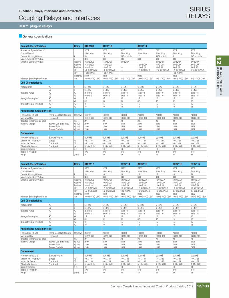
SIRIUS RELAYS
Siemens Canada Limited Industrial Control Product Catalog 2019 12/133
12
RELAYS, IN
TERFACES
& CO
NVERTERS
Siemens / Industrial Controls Previous folio: IC10 11/85
Contact Characteristics Units 3TX7109 3TX7110 3TX7111
Number and Type of Contacts SPDT SPDT SPDT DPDT DPDT 4PDT 4PDTContact Material Silver Alloy Silver Alloy Silver Alloy Silver Alloy Silver Alloy Silver Alloy Silver AlloyThermal (Carrying) Current A 20 15 3 (Bifurcated) 12 3 (Bifurcated) 6 3 (Bifurcated)Maximum Switching Voltage V 300 300 300 300 300 300 300Switching Current at Voltage Resistive 16A @240V 15A @240V 3A @240V — 3A @240V 6A @240V 3A @240V
Resistive 16A @120V 15A @120V — 12A @120V 3A @120V 6A @120V 3A @120VResistive 16A @ 28 15A @ 28 — 12A @ 28 3A @ 30 6A @ 28 3A @ 30HP 1/2 @ 120VAC 1/2 @ 120VAC — 1/3 @ 120VAC 1/16 @ 120VAC 1/3 @ 120VAC 1/16 @ 120VACHP 1 @ 240VAC 1 @ 240VAC — — — 1 @ 240VAC —Pilot Duty B300 B300 — B300 — B300 —
Minimum Switching Requirement mA 100 @ 5VDC (.5W) 100 @ 5VDC (.5W) 3 @ 17VDC (.4W) 100 @ 5VDC (.5W) 3 @ 17VDC (.4W) 100 @ 5VDC (.5W) 3 @ 17VDC (.4W)
Coil Characteristics
Voltage Range AC V 6…240 6…240 6…240 6…240 6…240 6…240 6…240DC V 6…125 6…125 6…125 6…125 6…125 6…125 6…125
Operating Range AC % 85 to 110 85 to 110 85 to 110 85 to 110 85 to 110 85 to 110 85 to 110DC % 80 to 110 80 to 110 80 to 110 80 to 110 80 to 110 80 to 110 80 to 110
Average Consumption AC VA 1.2 0.9 0.9 1.2 1.2 1.2 1.2DC W 0.9 0.7 0.7 0.9 0.9 0.9 0.9
Drop-out Voltage Threshold AC % 15 15 15 15 15 15 15DC % 10 10 10 10 10 10 10
Performance Characteristics
Electrical Life (UL508) Operations @ Rated Current (Resistive) 100,000 100,000 100,000 200,000 200,000 200,000 200,000Mechanical Life Unpowered 10,000,000 10,000,000 10,000,000 10,000,000 10,000,000 10,000,000 10,000,000Operating Time (response time) ms 20 20 20 20 20 20 20Dialectric Strength Between Coil and Contact V(rms) 2500 2500 2500 2500 2500 2500 2500
Between Poles V(rms) 1500 1500 1500 1500 1500 1500 1500Between Contacts V(rms) 1500 1500 1500 1500 1500 1500 1500
Environment
Product Certifications Standard Version UL,RoHS UL,RoHS UL,RoHS UL,RoHS UL,RoHS UL,RoHS UL,RoHSAmbient Air Temperature Storage °C -40…+85 -40…+85 -40…+85 -40…+85 -40…+85 -40…+85 -40…+85around the Device Operational °C -40…+55 -40…+55 -40…+55 -40…+55 -40…+55 -40…+55 -40…+55Vibration Resistance Operational g-n 3, 10 - 55 Hz 3, 10 - 55 Hz 3, 10 - 55 Hz 3, 10 - 55 Hz 3, 10 - 55 Hz 3, 10 - 55 Hz 3, 10 - 55 HzShock Resistance g-n 10 10 10 10 10 10 10Degree of Protection IP40 IP40 IP40 IP40 IP40 IP40 IP40Weight grams 36 29 29 36 36 36 36
Contact Characteristics Units 3TX7112 3TX7114 3TX7115 3TX7116 3TX7117
Number and Type of Contacts DPDT 3PDT DPDT DPDT 3PDT 3PDT 4PDTContact Material Silver Alloy Silver Alloy Silver Alloy Silver Alloy Silver Alloy Silver Alloy Silver AlloyThermal (Carrying) Current A 10 10 15 10 10 15 15Maximum Switching Voltage V 300 300 300 300 300 300 300Switching Current at Voltage Resistive 10A @240V 10A @240V 12A @277V 10A @277V 10A @277V 12A @277V 12A @277V
Resistive 10A @120V 10A @120V 15A @120V 10A @120V 10A @120V 15A @120V 15A @120VResistive 10A @ 28 10A @ 28 12A @ 28 10A @ 28 10A @ 28 12A @ 28 12A @ 28HP 1/3 @ 120VAC 1/3 @ 120VAC 1/2 @ 120VAC 1/3 @ 120VAC 1/3 @ 120VAC 1/2 @ 120VAC 1/2 @ 120VACHP 1/2 @ 240VAC 1/2 @ 240VAC 1 @ 240VAC 1/2 @ 240VAC 1/2 @ 240VAC 3/4 @ 240VAC 3/4 @ 240VACPilot Duty B300 B300 B300 B300 B300 B300 B300
Minimum Switching Requirement mA 100 @ 5VDC (.5W) 100 @ 5VDC (.5W) 100 @ 5VDC (.5W) 100 @ 5VDC (.5W) 100 @ 5VDC (.5W) 100 @ 5VDC (.5W) 100 @ 5VDC (.5W)
Coil Characteristics
Voltage Range AC V 6…240 6…240 6…240 6…240 6…240 6…240 6…240DC V 6…125 6…125 6…125 6…125 6…125 6…125 6…125
Operating Range AC % 85 to 110 85 to 110 85 to 110 85 to 110 85 to 110 85 to 110 85 to 110DC % 80 to 110 80 to 110 80 to 110 80 to 110 80 to 110 80 to 110 80 to 110
Average Consumption AC VA 1.2 1.2 1.2 1.2 1.2 1.5 1.5DC W 0.9 0.9 0.9 0.9 0.9 1.4 1.5
Drop-out Voltage Threshold AC % 15 15 15 15 15 15 15DC % 10 10 10 10 10 10 10
Performance Characteristics
Electrical Life (UL508) Operations @ Rated Current (Resistive) 200,000 200,000 100,000 100,000 100,000 200,000 200,000Mechanical Life Unpowered 10,000,000 10,000,000 10,000,000 10,000,000 10,000,000 10,000,000 10,000,000Operating Time (response time) ms 20 20 20 20 20 20 20Dialectric Strength Between Coil and Contact V(rms) 2500 2500 2500 2500 2500 2500 2500
Between Poles V(rms) 1500 1500 1500 1500 1500 2500 2500Between Contacts V(rms) 1500 1500 1500 1500 1500 1500 2500
Environment
Product Certifications Standard Version UL,RoHS UL,RoHS UL,RoHS UL,RoHS UL,RoHS UL,RoHS UL,RoHSAmbient Air Temperature Storage °C -40…+85 -40…+85 -40…+85 -40…+85 -40…+85 -40…+85 -40…+85around the Device Operational °C -40…+55 -40…+55 -40…+55 -40…+55 -40…+55 -40…+55 -40…+55Vibration Resistance Operational g-n 3, 10 - 55 Hz 3, 10 - 55 Hz 3, 10 - 55 Hz 3, 10 - 55 Hz 3, 10 - 55 Hz 3, 10 - 55 Hz 3, 10 - 55 HzShock Resistance g-n 10 10 10 10 10 10 10Degree of Protection IP40 IP40 IP40 IP40 IP40 IP40 IP40Weight grams 89 89 36 88 88 60 60
General specifications
Function Relays, Interfaces and Converters
Coupling Relays and Interfaces3TX71 plug-in relays
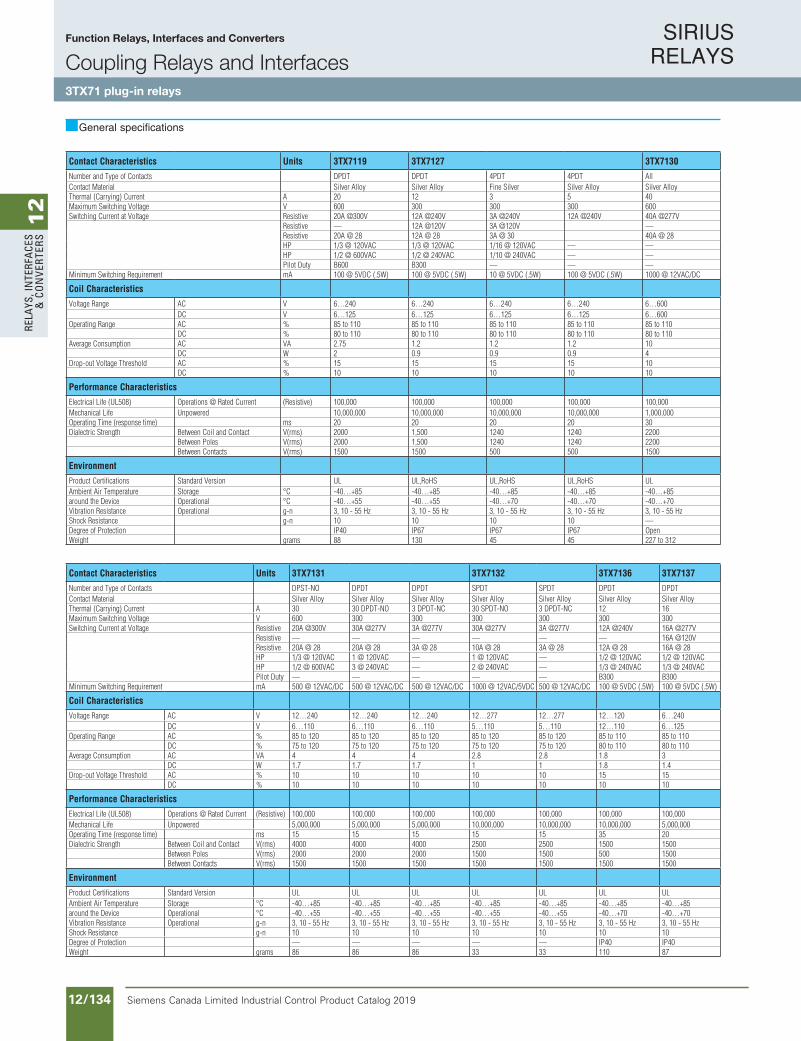
SIRIUS RELAYS
Siemens Canada Limited Industrial Control Product Catalog 201912/134
12
RELA
YS, I
NTE
RFA
CES
& C
ON
VERT
ERS
Siemens / Industrial Controls Previous folio: IC10 11/86
General specifications
Contact Characteristics Units 3TX7119 3TX7127 3TX7130
Number and Type of Contacts DPDT DPDT 4PDT 4PDT AllContact Material Silver Alloy Silver Alloy Fine Silver Silver Alloy Silver AlloyThermal (Carrying) Current A 20 12 3 5 40Maximum Switching Voltage V 600 300 300 300 600Switching Current at Voltage Resistive 20A @300V 12A @240V 3A @240V 12A @240V 40A @277V
Resistive — 12A @120V 3A @120V —Resistive 20A @ 28 12A @ 28 3A @ 30 40A @ 28HP 1/3 @ 120VAC 1/3 @ 120VAC 1/16 @ 120VAC — —HP 1/2 @ 600VAC 1/2 @ 240VAC 1/10 @ 240VAC — —Pilot Duty B600 B300 — — —
Minimum Switching Requirement mA 100 @ 5VDC (.5W) 100 @ 5VDC (.5W) 10 @ 5VDC (.5W) 100 @ 5VDC (.5W) 1000 @ 12VAC/DC
Coil Characteristics
Voltage Range AC V 6…240 6…240 6…240 6…240 6…600DC V 6…125 6…125 6…125 6…125 6…600
Operating Range AC % 85 to 110 85 to 110 85 to 110 85 to 110 85 to 110DC % 80 to 110 80 to 110 80 to 110 80 to 110 80 to 110
Average Consumption AC VA 2.75 1.2 1.2 1.2 10DC W 2 0.9 0.9 0.9 4
Drop-out Voltage Threshold AC % 15 15 15 15 10DC % 10 10 10 10 10
Performance Characteristics
Electrical Life (UL508) Operations @ Rated Current (Resistive) 100,000 100,000 100,000 100,000 100,000Mechanical Life Unpowered 10,000,000 10,000,000 10,000,000 10,000,000 1,000,000Operating Time (response time) ms 20 20 20 20 30Dialectric Strength Between Coil and Contact V(rms) 2000 1,500 1240 1240 2200
Between Poles V(rms) 2000 1,500 1240 1240 2200Between Contacts V(rms) 1500 1500 500 500 1500
Environment
Product Certifications Standard Version UL UL,RoHS UL,RoHS UL,RoHS ULAmbient Air Temperature Storage °C -40…+85 -40…+85 -40…+85 -40…+85 -40…+85around the Device Operational °C -40…+55 -40…+55 -40…+70 -40…+70 -40…+70Vibration Resistance Operational g-n 3, 10 - 55 Hz 3, 10 - 55 Hz 3, 10 - 55 Hz 3, 10 - 55 Hz 3, 10 - 55 HzShock Resistance g-n 10 10 10 10 —Degree of Protection IP40 IP67 IP67 IP67 OpenWeight grams 88 130 45 45 227 to 312
Contact Characteristics Units 3TX7131 3TX7132 3TX7136 3TX7137
Number and Type of Contacts DPST-NO DPDT DPDT SPDT SPDT DPDT DPDTContact Material Silver Alloy Silver Alloy Silver Alloy Silver Alloy Silver Alloy Silver Alloy Silver AlloyThermal (Carrying) Current A 30 30 DPDT-NO 3 DPDT-NC 30 SPDT-NO 3 DPDT-NC 12 16Maximum Switching Voltage V 600 300 300 300 300 300 300Switching Current at Voltage Resistive 20A @300V 30A @277V 3A @277V 30A @277V 3A @277V 12A @240V 16A @277V
Resistive — — — — — — 16A @120VResistive 20A @ 28 20A @ 28 3A @ 28 10A @ 28 3A @ 28 12A @ 28 16A @ 28HP 1/3 @ 120VAC 1 @ 120VAC — 1 @ 120VAC — 1/2 @ 120VAC 1/2 @ 120VACHP 1/2 @ 600VAC 3 @ 240VAC — 2 @ 240VAC — 1/3 @ 240VAC 1/3 @ 240VACPilot Duty — — — — — B300 B300
Minimum Switching Requirement mA 500 @ 12VAC/DC 500 @ 12VAC/DC 500 @ 12VAC/DC 1000 @ 12VAC/5VDC 500 @ 12VAC/DC 100 @ 5VDC (.5W) 100 @ 5VDC (.5W)
Coil Characteristics
Voltage Range AC V 12…240 12…240 12…240 12…277 12…277 12…120 6…240DC V 6…110 6…110 6…110 5…110 5…110 12…110 6…125
Operating Range AC % 85 to 120 85 to 120 85 to 120 85 to 120 85 to 120 85 to 110 85 to 110DC % 75 to 120 75 to 120 75 to 120 75 to 120 75 to 120 80 to 110 80 to 110
Average Consumption AC VA 4 4 4 2.8 2.8 1.8 3DC W 1.7 1.7 1.7 1 1 1.8 1.4
Drop-out Voltage Threshold AC % 10 10 10 10 10 15 15DC % 10 10 10 10 10 10 10
Performance Characteristics
Electrical Life (UL508) Operations @ Rated Current (Resistive) 100,000 100,000 100,000 100,000 100,000 100,000 100,000Mechanical Life Unpowered 5,000,000 5,000,000 5,000,000 10,000,000 10,000,000 10,000,000 5,000,000Operating Time (response time) ms 15 15 15 15 15 35 20Dialectric Strength Between Coil and Contact V(rms) 4000 4000 4000 2500 2500 1500 1500
Between Poles V(rms) 2000 2000 2000 1500 1500 500 1500Between Contacts V(rms) 1500 1500 1500 1500 1500 1500 1500
Environment
Product Certifications Standard Version UL UL UL UL UL UL ULAmbient Air Temperature Storage °C -40…+85 -40…+85 -40…+85 -40…+85 -40…+85 -40…+85 -40…+85around the Device Operational °C -40…+55 -40…+55 -40…+55 -40…+55 -40…+55 -40…+70 -40…+70Vibration Resistance Operational g-n 3, 10 - 55 Hz 3, 10 - 55 Hz 3, 10 - 55 Hz 3, 10 - 55 Hz 3, 10 - 55 Hz 3, 10 - 55 Hz 3, 10 - 55 HzShock Resistance g-n 10 10 10 10 10 10 10Degree of Protection — — — — — IP40 IP40Weight grams 86 86 86 33 33 110 87
Function Relays, Interfaces and Converters
Coupling Relays and Interfaces3TX71 plug-in relays
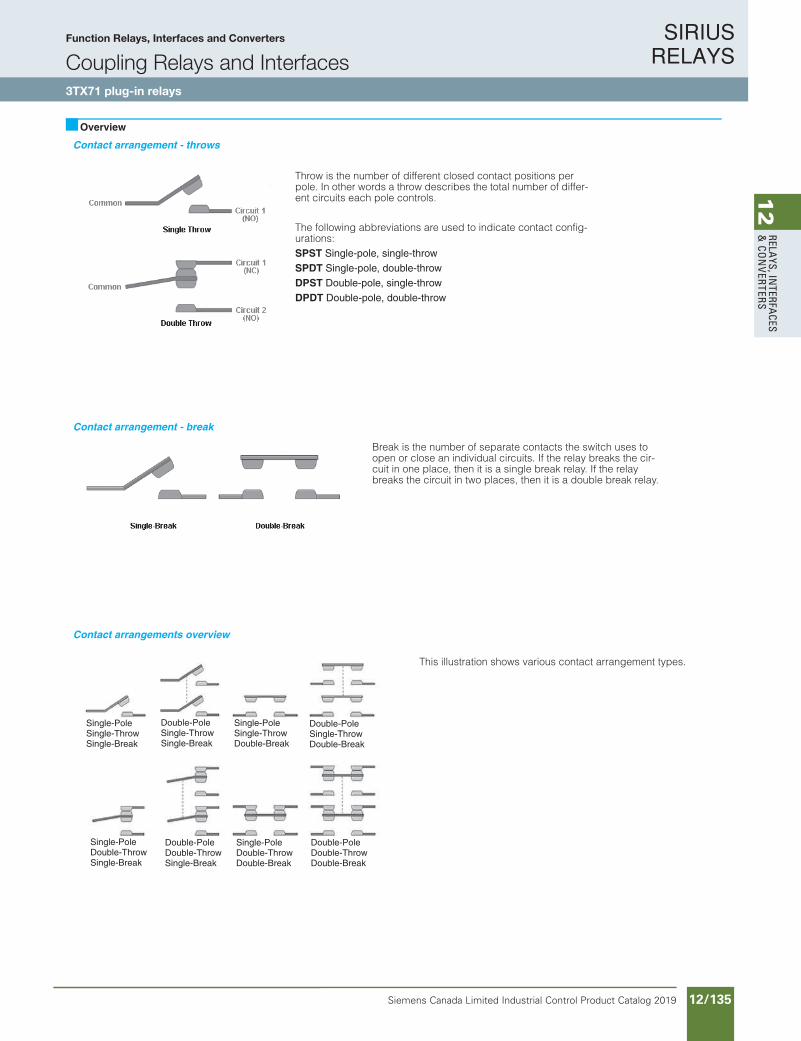
SIRIUS RELAYS
Siemens Canada Limited Industrial Control Product Catalog 2019 12/135
12
RELAYS, IN
TERFACES
& CO
NVERTERS
Siemens / Industrial Controls Previous folio: Siemens / Industrial Controls Previous folio: IC10 11/87
Contact arrangement - throws
Contact arrangement - break
Contact arrangements overview
Single-PoleSingle-ThrowSingle-Break
Double-PoleSingle-ThrowSingle-Break
Single-PoleSingle-ThrowDouble-Break
Double-PoleSingle-ThrowDouble-Break
Single-PoleDouble-ThrowSingle-Break
Double-PoleDouble-ThrowSingle-Break
Single-PoleDouble-ThrowDouble-Break
Double-PoleDouble-ThrowDouble-Break
Overview
Throw is the number of different closed contact positions per pole. In other words a throw describes the total number of differ-ent circuits each pole controls.
The following abbreviations are used to indicate contact config-urations:SPST Single-pole, single-throwSPDT Single-pole, double-throwDPST Double-pole, single-throwDPDT Double-pole, double-throw
Break is the number of separate contacts the switch uses to open or close an individual circuits. If the relay breaks the cir-cuit in one place, then it is a single break relay. If the relay breaks the circuit in two places, then it is a double break relay.
This illustration shows various contact arrangement types.
Function Relays, Interfaces and Converters
Coupling Relays and Interfaces3TX71 plug-in relays
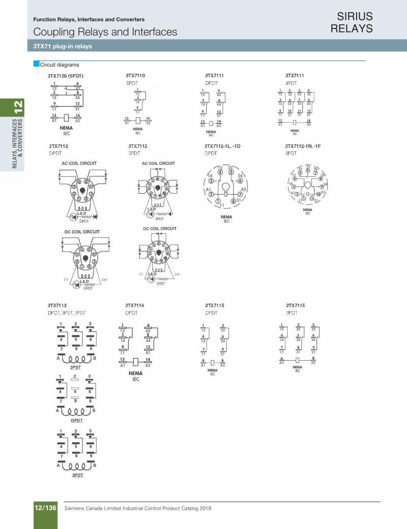
SIRIUS RELAYS
Siemens Canada Limited Industrial Control Product Catalog 201912/136
12
RELA
YS, I
NTE
RFA
CES
& C
ON
VERT
ERS
Circuit diagrams
Function Relays, Interfaces and Converters
Coupling Relays and Interfaces3TX71 plug-in relays
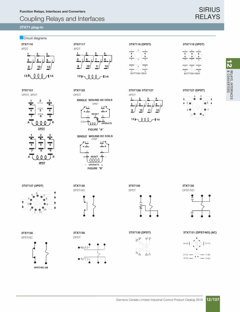
SIRIUS RELAYS
Siemens Canada Limited Industrial Control Product Catalog 2019 12/137
12
RELAYS, IN
TERFACES
& CO
NVERTERS
11/90 Siemens Industry, Inc.Industrial Controls Catalog
Siemens / Industrial Controls Previous folio:
3TX71 plug-in relays
Circuit diagrams
Function Relays, Interfaces and ConvertersCoupling Relays and Interfaces SIRIUS
RELAYS
3TX7119 (DPDT) 3TX7119 (3PDT)
3TX7127 (DPDT)
3TX7130 (DPDT)
3TX7127 (3PDT)
3TX7131 (DPST-NO) (AC)
3TX7130
SPST-NO
3TX7130
DPST-NO
3TX7130
SPDT
3TX7130
SPST-NC
3TX7130
DPDT
3TX7121
DPDT, 3PDT
3TX7125
DPDT
3TX7116
3PDT
3TX7126/ 3TX7127
4PDT
3TX7117
4PDT
10IC11_79-100.indd 90 3/2/11 4:28 PM
• Revised •03/21/2011
Circuit diagrams
Function Relays, Interfaces and Converters
Coupling Relays and Interfaces3TX71 plug-in
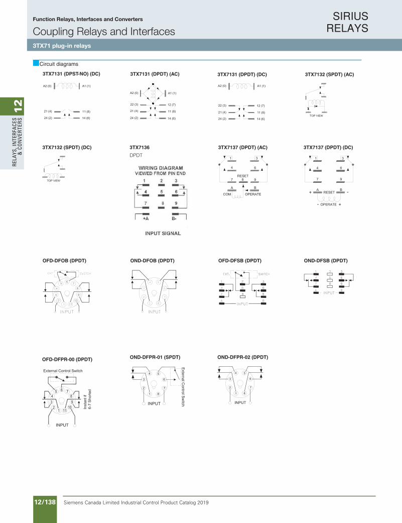
SIRIUS RELAYS
Siemens Canada Limited Industrial Control Product Catalog 201912/138
12
RELA
YS, I
NTE
RFA
CES
& C
ON
VERT
ERS
11/91Siemens Industry, Inc.Industrial Controls Catalog
3TX71 plug-in relays
Function Relays, Interfaces and ConvertersCoupling Relays and InterfacesSIRIUS
RELAYS
Circuit diagrams
OND-DFOB (DPDT) OND-DFSB (DPDT)OFD-DFOB (DPDT) OFD-DFSB (DPDT)
OFD-DFPR-00 (DPDT) OND-DFPR-01 (SPDT) OND-DFPR-02 (DPDT)
3TX7131 (DPDT) (AC)3TX7131 (DPST-NO) (DC) 3TX7132 (SPDT) (AC)3TX7131 (DPDT) (DC)
3TX7132 (SPDT) (DC) 3TX7137 (DPDT) (DC)3TX7137 (DPDT) (AC)3TX7136DPDT
• Revised •03/21/2011
Circuit diagrams
Function Relays, Interfaces and Converters
Coupling Relays and Interfaces3TX71 plug-in relays
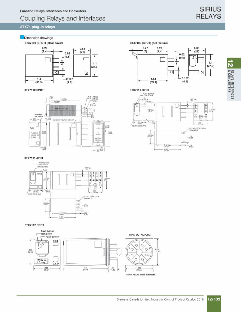
SIRIUS RELAYS
Siemens Canada Limited Industrial Control Product Catalog 2019 12/139
12
RELAYS, IN
TERFACES
& CO
NVERTERS
11/92 Siemens Industry, Inc.Industrial Controls Catalog
3TX71 plug-in relays
Function Relays, Interfaces and ConvertersCoupling Relays and Interfaces SIRIUS
RELAYS
Dimension drawings
3TX7110 SPDT
3TX7111 4PDT
3TX7111 DPDT
3TX7109 (SPDT) (clear cover)
0.83(21)
1.1(27.9)
0.187(4.8)
0.02(0.5)
0.29(7.4)
1.4(35.5)
3TX7109 (SPDT) (full feature)
0.83(21)
1.1(27.9)
1.54(39.1)
0.29(7.4)
0.02(0.5)
0.187(4.8)
0.27(7)
3TX7112 DPDT
• Revised •03/21/2011
Dimension drawings
Function Relays, Interfaces and Converters
Coupling Relays and Interfaces3TX71 plug-in relays
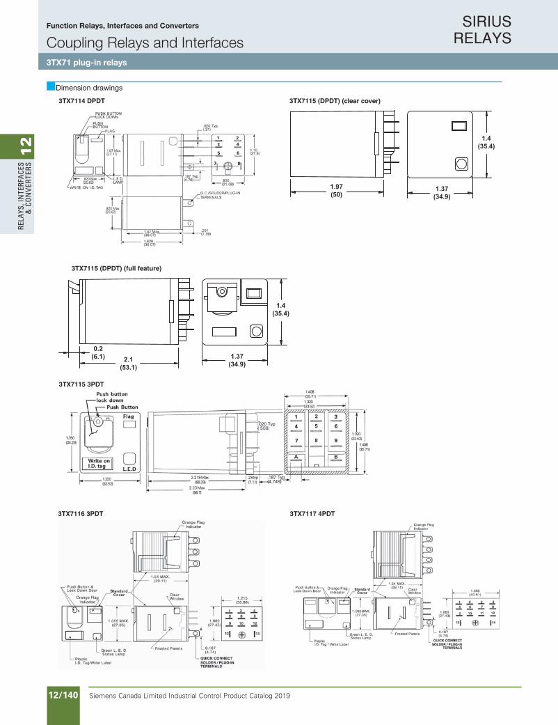
SIRIUS RELAYS
Siemens Canada Limited Industrial Control Product Catalog 201912/140
12
RELA
YS, I
NTE
RFA
CES
& C
ON
VERT
ERS
Dimension drawings
11/93Siemens Industry, Inc.Industrial Controls Catalog
3TX71 plug-in relays
Function Relays, Interfaces and ConvertersCoupling Relays and InterfacesSIRIUS
RELAYS
Dimension drawings
3TX7116 3PDT
3TX7114 DPDT
3TX7117 4PDT
3TX7115 (DPDT) (clear cover)
1.97(50)
1.37(34.9)
1.4(35.4)
3TX7115 (DPDT) (full feature)
0.2(6.1) 1.37
(34.9)
1.4(35.4)
2.1(53.1)
3TX7115 3PDT
• Revised •03/21/2011
Function Relays, Interfaces and Converters
Coupling Relays and Interfaces3TX71 plug-in relays

SIRIUS RELAYS
Siemens Canada Limited Industrial Control Product Catalog 2019 12/141
12
RELAYS, IN
TERFACES
& CO
NVERTERS
Dimension drawings
11/94 Siemens Industry, Inc.Industrial Controls Catalog
3TX71 plug-in relays
Function Relays, Interfaces and ConvertersCoupling Relays and Interfaces SIRIUS
RELAYS
Dimension drawings
3TX7120
3TX7119 DPDT
3TX7121/3TX7122 3TX7123
3TX7119 (3PDT)
6 5 4
A
7
B
8 9
1 2 3
1.40(35.5)
0.156(3.9)
1.53 (38.8)
1.90(48.4)
2.90(73.8)
2.50 (63.5)0.187 Quick Connects
• Revised •03/21/2011
Function Relays, Interfaces and Converters
Coupling Relays and Interfaces3TX71 plug-in relays

SIRIUS RELAYS
Siemens Canada Limited Industrial Control Product Catalog 201912/142
12
RELA
YS, I
NTE
RFA
CES
& C
ON
VERT
ERS
Dimension drawings
11/95Siemens Industry, Inc.Industrial Controls Catalog
3TX71 plug-in relays
Function Relays, Interfaces and ConvertersCoupling Relays and InterfacesSIRIUS
RELAYS
Dimension drawings
3TX7127 3PDT
3TX71263TX7123
3TX7127 4PDT
3TX7127 (DPDT)
2.1(50.3)
1.61 MAX(40.9)
1.44 MAX(36.6)
3TX7130 SPST NC 3TX7130 SPST NO
• Revised •03/21/2011
Function Relays, Interfaces and Converters
Coupling Relays and Interfaces3TX71 plug-in relays

SIRIUS RELAYS
Siemens Canada Limited Industrial Control Product Catalog 2019 12/143
12
RELAYS, IN
TERFACES
& CO
NVERTERS
Dimension drawings
11/96 Siemens Industry, Inc.Industrial Controls Catalog
3TX71 plug-in relays
Function Relays, Interfaces and ConvertersCoupling Relays and Interfaces SIRIUS
RELAYS
Dimension drawings
3TX7130 SPDT
3TX7130 DPDT
3TX7130 DPST NO
3TX7130 DPDT with magnetic blowout
3TX7131 (DPST-NO)
1.18(29.8)
1.35(34.25)
1(25.2)
2.04(51.65)
2.34(59.4)
2.68(68.05)
1.61(40.9)
0.19(4.65)
R0.09(R2.25)
FOR #8 SCREWS
0.25 X 0.032 (6.35 X 0.81)QUICK CONNECT TERMINALS
WITH SOLDER HOLE
3TX7131 (DPDT)
1.18(29.8)
1.35(34.25)
1(25.2)
2.04(51.65)
2.34(59.4)
2.68(68.05)
1.61(40.9)
0.19(4.65)
R0.09(R2.25)
FOR #8 SCREWS
0.25 X 0.032 (6.35 X 0.81)QUICK CONNECT TERMINALS
WITH SOLDER HOLE
• Revised •03/21/2011
Function Relays, Interfaces and Converters
Coupling Relays and Interfaces3TX71 plug-in relays

SIRIUS RELAYS
Siemens Canada Limited Industrial Control Product Catalog 201912/144
12
RELA
YS, I
NTE
RFA
CES
& C
ON
VERT
ERS
Dimension drawings
11/97Siemens Industry, Inc.Industrial Controls Catalog
3TX71 plug-in relays
Function Relays, Interfaces and ConvertersCoupling Relays and InterfacesSIRIUS
RELAYS
Dimension drawings
3TX7136
3TX7144-1E4
3TX7144-1E2
3TX7144-1E3
3TX7136 (DPDT Alternating)
1.40(35.6)
1.54(39.1)
2.63(66.8)
0.187 QUICK CONNECTS
CONTACTS7 & 4
7 & 1CLOSED9 & 6
9 & 3
INDICATING LEDS
3TX7137 (DPDT)
1.53 (38.8)
1.4(35.5)
1.9 (48.4)
0.032(0.812)
0.1875 QUICK CONNECTS
• Revised •03/21/2011
Function Relays, Interfaces and Converters
Coupling Relays and Interfaces3TX71 plug-in relays
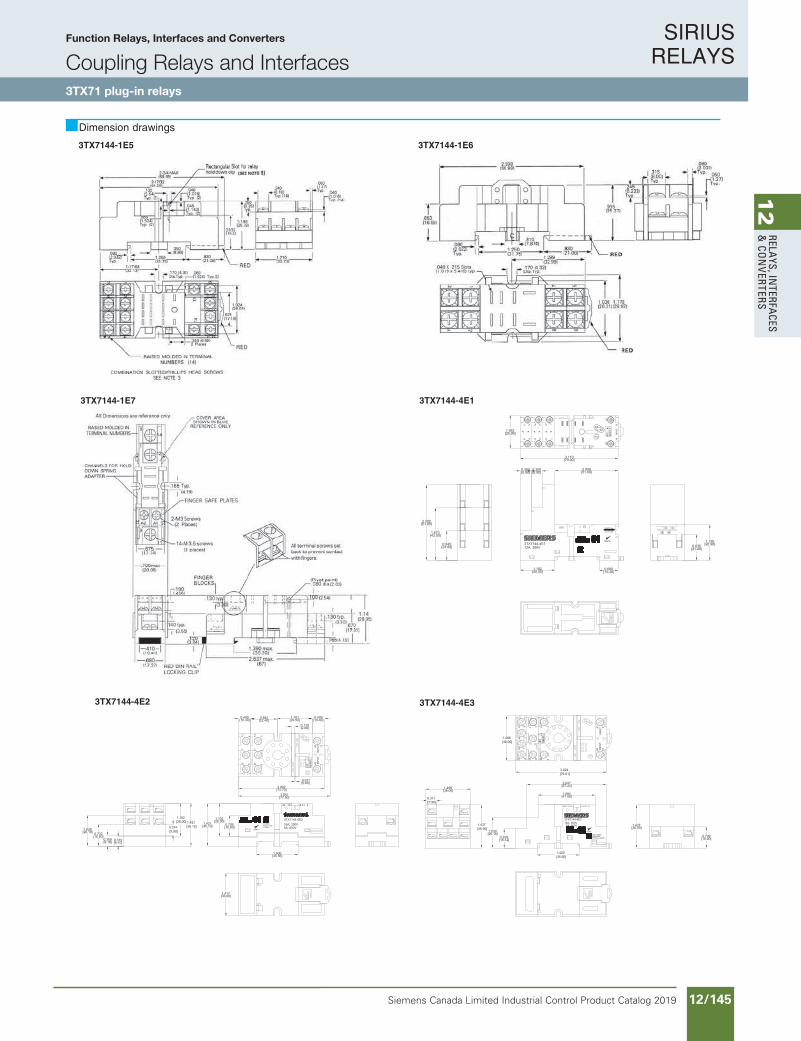
SIRIUS RELAYS
Siemens Canada Limited Industrial Control Product Catalog 2019 12/145
12
RELAYS, IN
TERFACES
& CO
NVERTERS
Dimension drawings
11/98 Siemens Industry, Inc.Industrial Controls Catalog
3TX71 plug-in relays
Function Relays, Interfaces and ConvertersCoupling Relays and Interfaces SIRIUS
RELAYS
Dimension drawings
3TX7144-1E6
3TX7144-1E7
3TX7144-1E5
3TX7144-4E1
3TX7144-4E33TX7144-4E2
• Revised •03/21/2011
Function Relays, Interfaces and Converters
Coupling Relays and Interfaces3TX71 plug-in relays
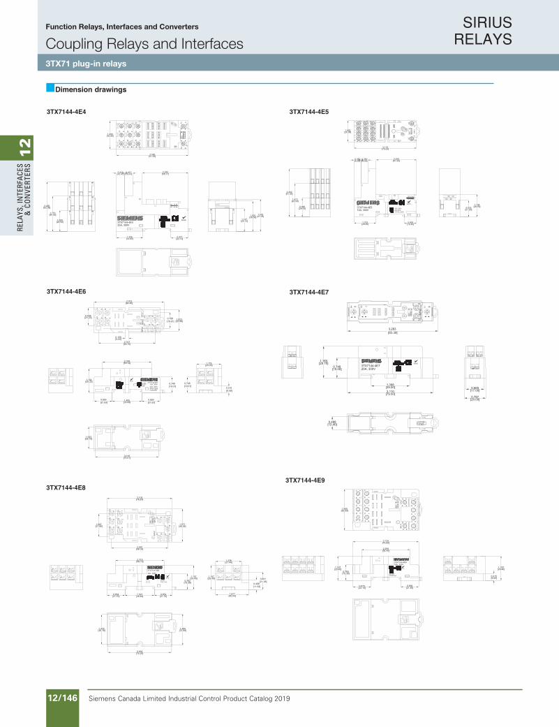
SIRIUS RELAYS
Siemens Canada Limited Industrial Control Product Catalog 201912/146
12
RELA
YS, I
NTE
RFA
CES
& C
ON
VERT
ERS
11/99Siemens Industry, Inc.Industrial Controls Catalog
3TX71 plug-in relays
Function Relays, Interfaces and ConvertersCoupling Relays and InterfacesSIRIUS
RELAYS
Dimension drawings
3TX7144-4E53TX7144-4E4
3TX7144-4E6
3TX7144-4E93TX7144-4E8
3TX7144-4E7
Function Relays, Interfaces and Converters
Coupling Relays and Interfaces3TX71 plug-in relays
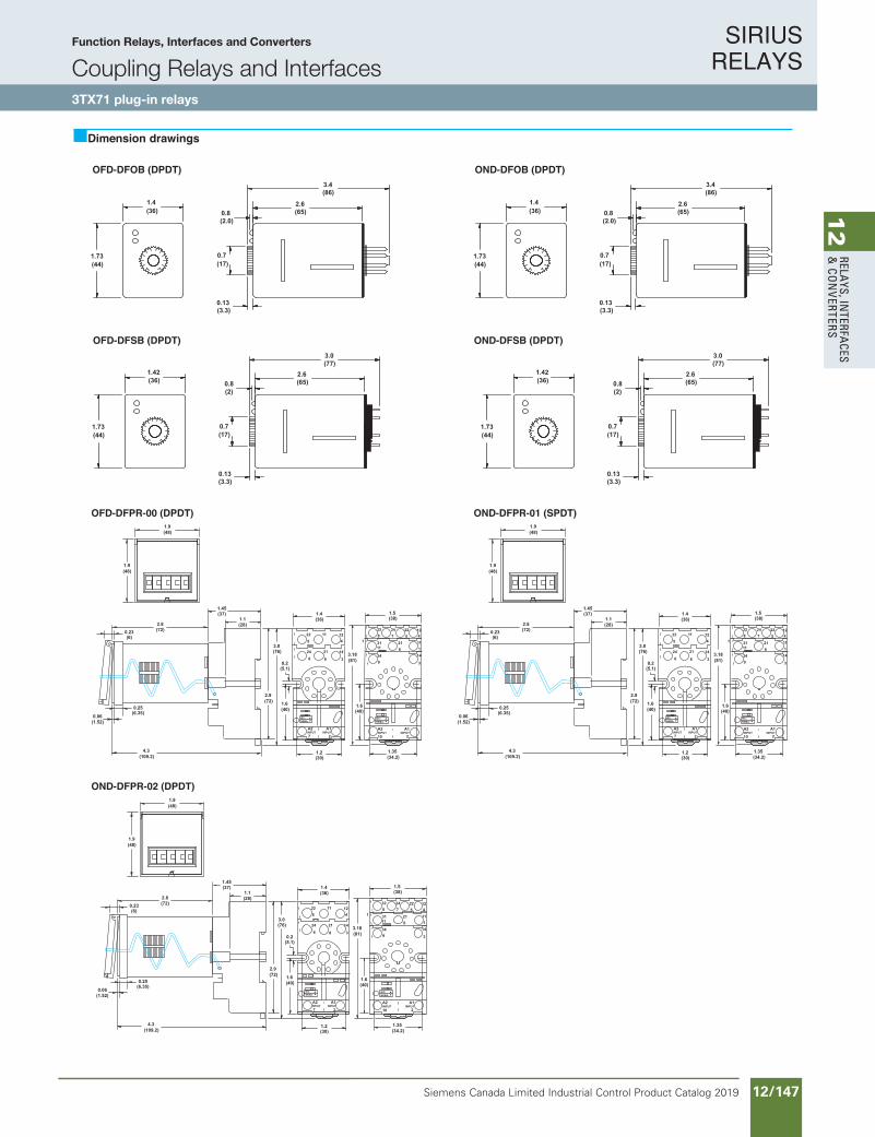
SIRIUS RELAYS
Siemens Canada Limited Industrial Control Product Catalog 2019 12/147
12
RELAYS, IN
TERFACES
& CO
NVERTERS
11/100 Siemens Industry, Inc.Industrial Controls Catalog
3TX71 plug-in relays
Function Relays, Interfaces and ConvertersCoupling Relays and Interfaces SIRIUS
RELAYS
Dimension drawings
OND-DFOB (DPDT)
1.73(44)
0.13(3.3)
0.7(17)
1.4(36)
(2.0)0.8 (65)
2.6
(86)3.4
OND-DFSB (DPDT)
1.73(44)
1.42(36)
(77)3.0
0.13(3.3)
0.7(17)
(2)0.8 (65)
2.6
OFD-DFPR-00 (DPDT)
(109.2)4.3
(36)1.4
(5.1)0.2
1.1(28)
114 1
12
14
3
A2
7
522
2124
6 8
A1
2
(72)2.9
(37)1.45
INPUTINPUT
(76)3.0
(40)1.6
(30)1.2
NEMA:IEC:
(48)1.9
(48)1.9
(6)0.23
0.06(1.52)
(72)2.8
(6.35)0.25
(38)1.5
(81)3.18
(40)1.6
(34.2)1.35
114
1
12
14
3
A2
10
522
21
24
6
7
A1
2INPUTINPUT
349
3111
328
NEMA:IEC:
OND-DFPR-02 (DPDT)
(109.2)4.3
(36)1.4
(5.1)0.2
1.1(28)
114 1
12
14
3
A2
7
522
2124
6 8
A1
2
(72)2.9
(37)1.45
INPUTINPUT
(76)3.0
(40)1.6
(30)1.2
NEMA:IEC:
(48)1.9
(48)1.9
(6)0.23
0.06(1.52)
(72)2.8
(6.35)0.25
(38)1.5
(81)3.18
(40)1.6
(34.2)1.35
114
1
12
14
3
A2
10
522
21
24
6
7
A1
2INPUTINPUT
349
3111
328
NEMA:IEC:
OFD-DFOB (DPDT)
1.73(44)
0.13(3.3)
0.7(17)
1.4(36)
(2.0)0.8 (65)
2.6
(86)3.4
OFD-DFSB (DPDT)
1.73(44)
1.42(36)
(77)3.0
0.13(3.3)
0.7(17)
(2)0.8 (65)
2.6
OND-DFPR-01 (SPDT)
(109.2)4.3
(36)1.4
(5.1)0.2
1.1(28)
114 1
12
14
3
A2
7
522
2124
6 8
A1
2
(72)2.9
(37)1.45
INPUTINPUT
(76)3.0
(40)1.6
(30)1.2
NEMA:IEC:
(48)1.9
(48)1.9
(6)0.23
0.06(1.52)
(72)2.8
(6.35)0.25
(38)1.5
(81)3.18
(40)1.6
(34.2)1.35
114
1
12
14
3
A2
10
522
21
24
6
7
A1
2INPUTINPUT
349
3111
328
NEMA:IEC:
Function Relays, Interfaces and Converters
Coupling Relays and Interfaces3TX71 plug-in relays