Embed Size (px)
Citation preview
SIPROTEC 5Communication protocolDNP3
V5.00
Manual
C53000-G5040-C006-3
Preface
Table of Contents
Protocol Characteristics 1Parameters and Properties 2Setting Parameters in DIGSI 5 3Communication Modules 4Commissioning and Diagnostics 5Troubleshooting 6Glossary
Index
iiNOTE
For your own safety, observe the warnings and safety instructions contained in this document, if available.
Disclaimer of LiabilityThis document has been subjected to rigorous technicalreview before being published. It is revised at regular inter-vals, and any modifications and amendments are includedin the subsequent issues. The content of this documenthas been compiled for information purposes only. AlthoughSiemens AG has made best efforts to keep the documentas precise and up-to-date as possible, Siemens AG shallnot assume any liability for defects and damage whichresult through use of the information contained herein.This content does not form part of a contract or of businessrelations; nor does it change these. All obligations ofSiemens AG are stated in the relevant contractual agree-ments.Siemens AG reserves the right to revise this documentfrom time to time.Document version: C53000-G5040-C006-3.00Edition: 02.2014Version of the product described: V5.00
CopyrightCopyright © Siemens AG 2014. All rights reserved.The disclosure, duplication, distribution and editing of thisdocument, or utilization and communication of the contentare not permitted, unless authorized in writing. All rights,including rights created by patent grant or registration of autility model or a design, are reserved.Registered TrademarksSIPROTEC®, DIGSI®, SIGUARD®, SIMEAS®, and SICAM®
are registered trademarks of Siemens AG. Any unauthor-ized use is illegal. All other designations in this documentcan be trademarks whose use by third parties for their ownpurposes can infringe the rights of the owner.

Preface
Purpose of the Manual
This manual contains information about:• Communication within the SIPROTEC 5 family of devices and to higher-level control centers
• Installation of the modules
• Setting parameters in DIGSI 5
• Information on commissioning
Target Audience
Protection system engineers, commissioning engineers, persons entrusted with the setting, testing and main-tenance of automation, selective protection and control equipment, and operational crew in electrical installa-tions and power plants.
Scope
This manual applies to the SIPROTEC 5 device family.
Further Documentation
[dwprecom-221012-01.tif, 1, en_US]
• Device manualsEach Device manual describes the functions and applications of a specific SIPROTEC 5 device. Theprinted manual and the online help for the device have the same informational structure.
SIPROTEC 5, Communication protocol, Manual 3C53000-G5040-C006-3, Edition 02.2014

• Hardware manualThe Hardware manual describes the hardware building blocks and device combinations of theSIPROTEC 5 device family.
• Operating manualThe Operating manual describes the basic principles and procedures for operating and assembling thedevices of the SIPROTEC 5 range.
• Communication protocol manualsThe Communication protocol manuals contain a description of a specific protocol for communicationwithin the SIPROTEC 5 device family and to higher-level network control centers.
• Product informationThe Product information includes general information about device installation, technical data, limitingvalues for input and output modules, and conditions when preparing for operation. This document isprovided with each SIPROTEC 5 device.
• Engineering GuideThe Engineering Guide describes the essential steps when engineering with DIGSI 5. In addition, theEngineering Guide shows you how to load a planned configuration to a SIPROTEC 5 device and updatethe functionality of the SIPROTEC 5 device.
• DIGSI 5 online helpThe DIGSI 5 online help contains a help package for DIGSI 5 and CFC.The help package for DIGSI 5 includes a description of the basic operation of software, the DIGSI princi-ples and editors. The help package for CFC includes an introduction to CFC programming, basic exam-ples of working with CFC, and a reference chapter with all the CFC blocks available for the SIPROTEC 5range.
• SIPROTEC 5/DIGSI 5 TutorialThe tutorial on the DVD contains brief information about important product features, more detailed infor-mation about the individual technical areas, as well as operating sequences with tasks based on prac-tical operation and a brief explanation.
• System catalogThe system catalog describes the SIPROTEC 5 system features.
• Device catalogsThe device catalogs describe device-specific features such as functional scope, hardware and applica-tions.
Indication of Conformity
This product complies with the directive of the Council of the European Communi-ties on harmonization of the laws of the Member States relating to electromagneticcompatibility (EMC Council Directive 2004/108/EC) and concerning electrical equip-ment for use within specified voltage limits (Low Voltage Directive 2006/95/EC).This conformity has been proved by tests performed according to the Council Direc-tive in accordance with the generic standards EN 61000-6-2 and EN 61000-6-4 (forEMC directive) and with the standard EN 60255-27 (for Low Voltage Directive) bySiemens AG.The device is designed and manufactured for application in an industrial environ-ment.The product conforms with the international standards of IEC 60255 and theGerman standard VDE 0435.
Other Standards
IEEE Std C 37.90The technical data of the product is approved in accordance with UL.
Preface
4 SIPROTEC 5, Communication protocol, ManualC53000-G5040-C006-3, Edition 02.2014

File E194016
[scpreful-070211-01.tif, 1, --_--]
Additional Support
For questions about the system, please contact your Siemens sales partner.
Support
Our Customer Support Center provides a 24-hour service.Phone: +49 (180) 524-8437Fax: +49 (180) 524-2471E-Mail: [email protected]
Training Courses
Inquiries regarding individual training courses should be addressed to our Training Center:Siemens AGSiemens Power Academy TDHumboldtstraße 5990459 NürnbergPhone: +49 (911) 433-7415Fax: +49 (911) 433-5482E-Mail: [email protected]: http://www.siemens.com/poweracademy
Notes on Safety
This document is not a complete index of all safety measures required for operation of the equipment(module or device). However, it comprises important information that must be followed for personal safety, aswell as to avoid material damage. Information is highlighted and illustrated as follows according to the degreeof danger:
! DANGERDANGER means that death or severe injury will result if the measures specified are not taken.
² Comply with all instructions, in order to avoid death or severe injuries.
! WARNINGWARNING means that death or severe injury may result if the measures specified are not taken.
² Comply with all instructions, in order to avoid death or severe injuries.
Preface
SIPROTEC 5, Communication protocol, Manual 5C53000-G5040-C006-3, Edition 02.2014

! CAUTIONCAUTION means that medium-severe or slight injuries can occur if the specified measures are not taken.
² Comply with all instructions, in order to avoid moderate or minor injuries.
NOTICENOTICE means that property damage can result if the measures specified are not taken.
² Comply with all instructions, in order to avoid property damage.
iiNOTE
Important information about the product, product handling or a certain section of the documentation, whichmust be given particular attention.
Qualified Electrical Engineering Personnel
Only qualified electrical engineering personnel may commission and operate the equipment (module, device)described in this document. Qualified electrical engineering personnel in the sense of this manual are peoplewho can demonstrate technical qualifications as electrical technicians. These persons may commission,isolate, ground and label devices, systems and circuits according to the standards of safety engineering.
Proper Use
The equipment (device, module) may be used only for such applications as set out in the catalogs and thetechnical description, and only in combination with third-party equipment recommended and approved bySiemens.Problem-free and safe operation of the product depends on the following:• Proper transport
• Proper storage, setup and installation
• Proper operation and maintenance
When electrical equipment is operated, hazardous voltages are inevitably present in certain parts. If properaction is not taken, death, severe injury or property damage can result:• The equipment must be grounded at the grounding terminal before any connections are made.
• All circuit components connected to the power supply may be subject to dangerous voltage.
• Hazardous voltages may be present in equipment even after the supply voltage has been disconnected(capacitors can still be charged).
• Operation of equipment with exposed current-transformer circuits is prohibited. Before disconnecting theequipment, ensure that the current-transformer circuits are short-circuited.
• The limiting values stated in the document may not be exceeded. This must also be considered duringtesting and commissioning.
Preface
6 SIPROTEC 5, Communication protocol, ManualC53000-G5040-C006-3, Edition 02.2014

Table of Contents
Preface................................................................................................................................................................3
1 Protocol Characteristics...................................................................................................................................... 91.1 Protocol Structure.................................................................................................................101.1.1 Description...................................................................................................................... 101.1.2 Physical Layer.................................................................................................................101.1.3 Data-Link Layer...............................................................................................................111.1.4 Pseudo Transport Layer................................................................................................. 121.1.5 Application Layer............................................................................................................ 121.2 Ethernet Services................................................................................................................. 161.2.1 Activation and Ability to Switch Off Services...................................................................161.2.2 DCP................................................................................................................................ 161.2.3 SNMP..............................................................................................................................171.2.3.1 Settings for SNMP.....................................................................................................171.2.4 SNTP.............................................................................................................................. 171.2.5 DHCP..............................................................................................................................171.2.6 RSTP.............................................................................................................................. 171.2.6.1 Description................................................................................................................ 171.2.7 PRP.................................................................................................................................171.2.8 HSR................................................................................................................................ 181.2.9 Homepage...................................................................................................................... 181.2.9.1 Content and Structure............................................................................................... 181.3 Transfer through Ethernet.....................................................................................................211.3.1 Requirements for the Physical, Transport, and Application Layers................................ 211.3.2 Acknowledgments...........................................................................................................211.3.3 Message Transmission................................................................................................... 211.4 Functional Scope..................................................................................................................221.5 Fault Record Transfer...........................................................................................................241.6 Operating Modes.................................................................................................................. 261.7 Time Synchronization........................................................................................................... 271.8 Amount of Mappable Information..........................................................................................28
2 Parameters and Properties............................................................................................................................... 292.1 Settings for the Serial Connection........................................................................................ 302.2 Settings for Communication through Ethernet......................................................................33
3 Setting Parameters in DIGSI 5..........................................................................................................................373.1 Communication-Module Selection........................................................................................383.2 Communication-Module Configuration................................................................................. 393.3 Signals to the Communication Modules............................................................................... 42
SIPROTEC 5, Communication protocol, Manual 7C53000-G5040-C006-3, Edition 02.2014

3.4 Select Mapping.....................................................................................................................433.5 Adapting Mappings...............................................................................................................443.5.1 Description...................................................................................................................... 443.5.2 Indications.......................................................................................................................443.5.3 Commands......................................................................................................................443.5.4 Measured Values............................................................................................................ 453.5.5 Counter Values............................................................................................................... 473.5.6 Mapping on the Object Status.........................................................................................483.5.7 Number Representation Depending on the Parameterization........................................ 483.5.8 Copying Mapping Rows.................................................................................................. 493.6 Copying Mappings................................................................................................................523.7 Exporting Mappings..............................................................................................................533.8 Changing Mappings..............................................................................................................543.9 Time Synchronization........................................................................................................... 55
4 Communication Modules.................................................................................................................................. 574.1 Overview ..............................................................................................................................584.2 Communication Applications of the Plug-In Module ............................................................ 624.3 Serial Communication Modules for Short Distances............................................................ 644.3.1 Special Features of the Serial Electrical Modules...........................................................644.3.2 USART-AB-1EL.............................................................................................................. 654.3.3 USART-AC-2EL.............................................................................................................. 664.3.4 USART-AD-1FO............................................................................................................. 664.3.5 USART-AE-2FO..............................................................................................................674.4 Ethernet Modules..................................................................................................................684.4.1 Operation of Ethernet Modules....................................................................................... 684.4.2 ETH-BA-2EL................................................................................................................... 694.4.3 ETH-BB-2FO ..................................................................................................................704.5 Configuration, Installation, Replacement..............................................................................714.5.1 Fasteners........................................................................................................................ 714.5.2 Installation.......................................................................................................................714.5.3 Replacement...................................................................................................................72
5 Commissioning and Diagnostics.......................................................................................................................755.1 Diagnostic Information..........................................................................................................765.2 Diagnostic Variables.............................................................................................................78
6 Troubleshooting................................................................................................................................................ 816.1 Troubleshooting....................................................................................................................82
Glossary............................................................................................................................................................83
Index................................................................................................................................................................. 87
Table of Contents
8 SIPROTEC 5, Communication protocol, ManualC53000-G5040-C006-3, Edition 02.2014

Protocol Characteristics
1.1 Protocol Structure 10
1.2 Ethernet Services 161.3 Transfer through Ethernet 21
1.4 Functional Scope 221.5 Fault Record Transfer 24
1.6 Operating Modes 261.7 Time Synchronization 27
1.8 Amount of Mappable Information 28
1
SIPROTEC 5, Communication protocol, Manual 9C53000-G5040-C006-3, Edition 02.2014

Protocol Structure
Description
DNP3 has a graded architecture. Instead of the OSI model, however, a simplified 3-layer model suggested bythe IEC is used. This model was named Enhanced Performance Architecture (EPA) by the IEC. However,DNP3 adds a 4th layer, a pseudo transport layer, with which messages can be segmented. The usedgraphics were taken from the DNP3-Spec-V1-Introduction-20071215.pdf standard.
[dwepadia-060511-01.vsd, 1, en_US]
Figure 1-1 EPA diagram
The SIPROTEC 5 device supports the DNP3, level 2 version.Additional information is available in the following documents:• DNP3Spec-V1-Introduction-20071215.pdf
• DNP3Spec-V2-Part1-ApplicationLayer- 20090315.pdf
• DNP3Spec-V2-Part2-ApplicationLayer- 20090315.pdf
• DNP3Spec-V2-Part3-ApplicationLayer-20071215.pdf
• DNP3Spec-V2-Sup1-SecureAuthentication-20100317.pdf
• DNP3Spec-V3-TransportFunction-20070203.pdf
• DNP3Spec-V4-DataLinkLayer-20070203.pdf
• DNP3Spec-V5-LayerIndependent-20071215.pdf
• DNP3Spec-V6-Part1-ObjectLibraryBasics-20071215.pdf
• DNP3Spec-V6-Part2-Objects-20090315.pdf
• DNP3Spec-V6-Part3-ParsingCodes-20090420.pdf
• DNP3Spec-V7-IPNetworking-20070711.pdf
• DNP3Spec-V8-Apdx1-DeviceProfile-20100223.pdf
• DNP3Spec-V8-Interoperability-20090611.pdf
Physical Layer
The physical layer mainly deals with the physical media through which the protocol is transferred. The phys-ical layer deals with, for example, the condition of the media (free or occupied) and the synchronizationthrough the media (start and stop).
1.1
1.1.1
1.1.2
Protocol Characteristics1.1 Protocol Structure
10 SIPROTEC 5, Communication protocol, ManualC53000-G5040-C006-3, Edition 02.2014
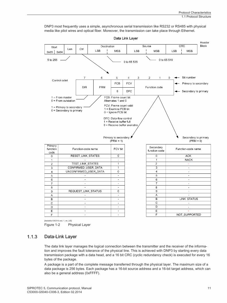
DNP3 most frequently uses a simple, asynchronous serial transmission like RS232 or RS485 with physicalmedia like pilot wires and optical fiber. Moreover, the transmission can take place through Ethernet.
[dwdalila-030314.vsd, 1, en_US]
Figure 1-2 Physical Layer
Data-Link Layer
The data link layer manages the logical connection between the transmitter and the receiver of the informa-tion and improves the fault tolerance of the physical line. This is achieved with DNP3 by starting every datatransmission package with a data head, and a 16 bit CRC (cyclic redundancy check) is executed for every 16bytes of the package.A package is a part of the complete message transferred through the physical layer. The maximum size of adata package is 256 bytes. Each package has a 16-bit source address and a 16-bit target address, which canalso be a general address (0xFFFF).
1.1.3
Protocol Characteristics1.1 Protocol Structure
SIPROTEC 5, Communication protocol, Manual 11C53000-G5040-C006-3, Edition 02.2014

The 10-byte data link layer head contains:• The address information
• A 16-bit start code
• The frame length
• A data link control byte
The data link control byte displays the cause of the data transmission and the status of the logical connection.The data link control byte can have the following values:• ACK (data link confirmation)
• NACK (negative confirmation)
• Connection needs to be reset
• Connection is reset
• Data link confirmation from the package required
If a data link confirmation is needed, the receiver must respond with an ACK data package if the package wasreceived and the CRC checks were successful. If no data link confirmation is requested, no response isrequired.
Pseudo Transport Layer
The pseudo transport layer segments application messages in multiple data transmission packages.The pseudo transport layer implements an individual byte function code for every package. The byte functioncode displays what the data transmission package is:• The 1st package of a message
• The last package of a message
• Both (for individual message packages)
The function code delivers a running package number. This subsequent package number is increased witheach package and allows the receiver's transport layer to analyze the package.
[dwtrfnct-030314, 1, en_US]
Figure 1-3 Pseudo Transport Layer
Application Layer
The application layer responds to received messages and creates messages based on the necessity andavailability of the user data. As soon as messages are available, they are sent to the pseudo transport layer.The messages are segmented here, sent to the data link layer and transferred through the physical layer.If the data that is to be sent is too large for an individual application message, a number of applicationmessages can be created and sent in a sequential manner. Each message is an independent applicationmessage. Their only connection with each other is the label in all messages that says that more messageswill follow. Only the last message does not contain this label. Each application message refers to a fragmentdue to the fact that the user data may be fragmented. A message can thus be a single fragment message ora multi-fragment message.Application packages from DNP3 slaves are normally responses to queries. A DNP3 slave can also send amessage without a request, thus, an unsolicited response.As in the data link layer, application fragments can be sent with a confirmation request. An application confir-mation indicates that a message was not only received, but rather it was also syntactically analyzed without
1.1.4
1.1.5
Protocol Characteristics1.1 Protocol Structure
12 SIPROTEC 5, Communication protocol, ManualC53000-G5040-C006-3, Edition 02.2014

any errors. A data transmission confirmation or an ACK indicate only that the transmission package wasreceived and that the CRC checks were error-free.Each application package begins with an application layer header, followed by one or more object heads/object data. The application layer header contains an application control code and an application functioncode.If one of the following conditions is fulfilled, then the application control code contains labels:• The package is a multi-package message.
• An application layer acknowledgment is requested for the package.
• The package is not requested.
The application control code contains a continual application layer number. With this application layernumber, the receiving application layer can recognize alien packages or lost packages.The application function code in the header of the application layer indicates the cause or the requested func-tion in the message. While DNP3 allows a number of data types in a single message, it also allows only anindividual query for a data type within the message.Examples for application function codes include:• Acknowledgments for confirmation on the application layer
• Read and write
• Select and execute (SBO (select before operate), controls)
• Direct control (for switching objects without SBO)
• Save and delete (for counters)
• Restart (both cold and warm)
• Enable and disable non-requested messages
• Selection of the classes
The application function code in the header of the application layer applies for all object headers. Thus, theapplication function code applies for all data within the message package.
Protocol Characteristics1.1 Protocol Structure
SIPROTEC 5, Communication protocol, Manual 13C53000-G5040-C006-3, Edition 02.2014

[dwaplay1-030314.vsd, 1, en_US]
Figure 1-4 Application layer - part 1
Protocol Characteristics1.1 Protocol Structure
14 SIPROTEC 5, Communication protocol, ManualC53000-G5040-C006-3, Edition 02.2014
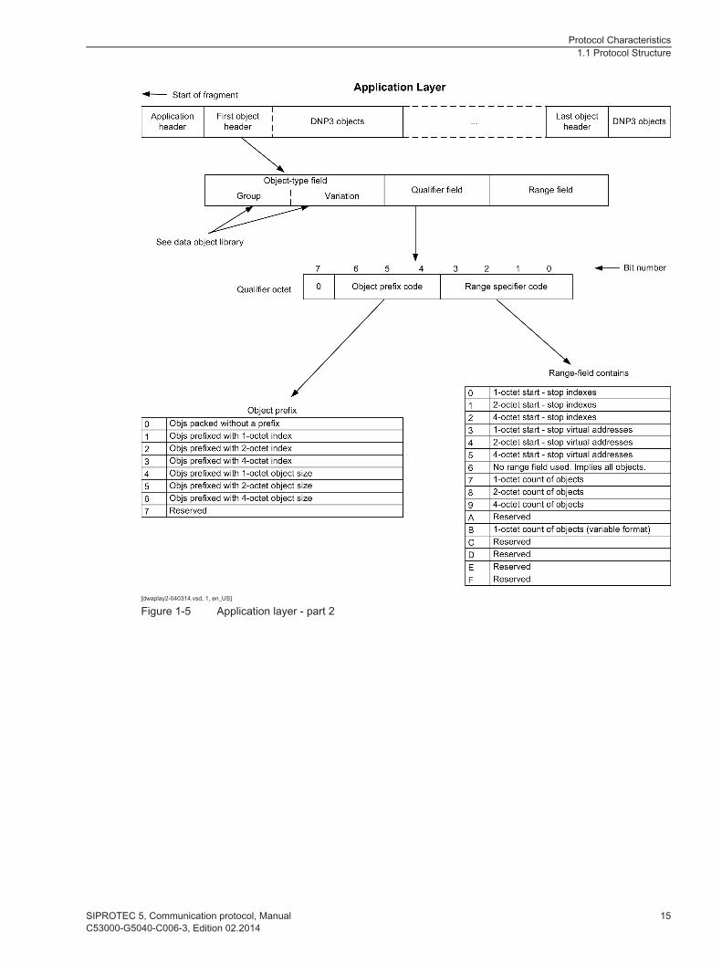
[dwaplay2-040314.vsd, 1, en_US]
Figure 1-5 Application layer - part 2
Protocol Characteristics1.1 Protocol Structure
SIPROTEC 5, Communication protocol, Manual 15C53000-G5040-C006-3, Edition 02.2014
Ethernet Services
Activation and Ability to Switch Off Services
The following additional Ethernet services are available for the integrated Ethernet interface (Port J) of thedevice:• DIGSI 5 protocol (always available)
• DCP
• SNTP
The following additional Ethernet services are available for the Ethernet communication module:• DIGSI 5 protocol (always available)
• DCP
• SNMP
• SNTP
• SUP Ethernet (for connecting external analog units)
• Homepage
• RSTP, PRP or HSR
With the exception of the DIGSI 5 protocol, all additional Ethernet services can be switched on and off foreach Ethernet interface on the device. As a result, you can decide for yourself under security aspects whetherthe device should react to SNMP access or not.Additional information on SUP Ethernet is available in the following manuals: SIPROTEC Transformer Differ-ential Protection 7UT85 7UT86 7UT87, SIPROTEC Distance Protection, Line Differential Protection, andOvercurrent Protection for 3-pole Tripping 7SA84, 7SD84, 7SA86, 7SD86, 7SL86, 7SJ86, and SIPROTECDistance Protection, Line Differential Protection, and Switch Management for 1-pole and 3-pole Tripping7SA87, 7SD87, 7SL87, 7VK87.
Activating Ethernet Service
² To switch on an Ethernet service in the device, activate the corresponding check box in the channelsettings of the Ethernet communication module or for the integrated Ethernet interface.
Deactivating Ethernet Service
² To switch off an Ethernet service in the device, deactivate the corresponding check box.You will find additional information regarding network security in the Security Blueprint.
DCP
The Discovery and Basic Configuration Protocol (DCP) is used for automatic recognition of devices without aconfigured IP address. DIGSI 5 can find all SIPROTEC 5 devices in the network using DCP.DCP is not required for the functionality of communication protocols. The protocol can however in parallel beconfigured for a DIGSI Life List functionality.The DIGSI Life List shows the connected devices. You can monitor and process these devices via the DIGSILife List.If you also desire a DIGSI Life List functionality through the LAN, then you must activate DCP.If you create a new device in DIGSI or add an Ethernet communication module to the device, DCP is acti-vated. If you change this recommended default and want to switch off the DIGSI Life List functionality in thedevice, deactivate the DCP check box in the channel settings of the Ethernet communication module or forthe integrated Ethernet interface.
1.2
1.2.1
1.2.2
Protocol Characteristics1.2 Ethernet Services
16 SIPROTEC 5, Communication protocol, ManualC53000-G5040-C006-3, Edition 02.2014

SNMP
Settings for SNMP
SNMPv3 (SNMP - Simple Network Management Protocol) is implemented in all Ethernet communicationmodules.As default, SNMP is deactivated. If you want to switch on SNMP in the device, activate the SNMP check boxin the channel settings of the Ethernet communication module.Then, if necessary, you can set the UDP port where the SNMP agent (Ethernet communication module)receives the queries. The standard setting for the UDP port is 161 and normally should not be changed.
Parameter Name SettingsUDP port for SNMP agent UDP port of the SNMP agent (device)
Standard setting = 161
SNMP allows the state query of these modules. For the display of MIB information (MIB – Management Infor-mation Base), an MIB browser and the description files are required.
SNTP
The Simple Network Time Protocol is used to synchronize clocks via the Internet. With SNTP, clientcomputers can synchronize their clocks with a time server via the Internet.SNTP is available for the integrated Ethernet interface (Port J) of the device:SNTP uses UDP port 123 (UDP - User Datagram Protocol).
DHCP
The Dynamic Host Configuration Protocol (DHCP) enables a client, in this case the Ethernet interface, toaccess IP address and configuration data from a DHCP server. In this case, a DHCP server has to be avail-able in the network. If DHCP is activated, you do not have to configure the Ethernet interface network settingsyourself.
RSTP
Description
The Rapid Spanning Tree Protocol (RSTP) serves for the reorganization of the network structure in the eventof an error. In other words, RSTP reroutes the data to another path after the failure of a network path.
PRP
PRP (Parallel Redundancy Protocol) is a redundancy protocol for Ethernet networks. This protocol is speci-fied in the norm IEC 62439-3. In comparison to conventional redundancy procedures, for example, RSTP(Rapid Spanning Tree Protocol, IEEE 802.1D-2004), PRP offers a switchover without interruptions. Thisavoids a dead time in the event of a fault, and thus the highest availability.Previous redundancy methods are based on mechanisms where the power-system components (switchesand bridges) agree with each other and find the best communication path for normal operation.In the event of a fault, for example, in a cable, an optical fiber, or in case of a switch failure, the interruption isdetected and alternative paths are found in the network and connected. No communication can take placeduring this switching procedure. Depending on the size and on the configuration of the Ethernet network, thisstate can last for 10 ms up to around 1 s. A protocol extension in the end device is not necessary in this casebecause the protocol is implemented in the switches.PRP adopts a different approach.
1.2.3
1.2.3.1
1.2.4
1.2.5
1.2.6
1.2.6.1
1.2.7
Protocol Characteristics1.2 Ethernet Services
SIPROTEC 5, Communication protocol, Manual 17C53000-G5040-C006-3, Edition 02.2014
The redundancy procedure is generated in the end device itself. The procedure is simple: The redundant enddevice has 2 Ethernet interfaces with the same address (DAN, Double Attached Node). Then, the same indi-cation is sent twice, with PRP (parallel) via 2 separated networks. Both indications are unambiguously identi-fied with a sequence number.The receiver takes the information that arrives first, stores the ID of the information in a duplicate filter usingthe source address and the sequence number of the information. Thereby, the receiver recognizes the 2ndredundant information and discards it.. This redundant information is then discarded.If the 1st indication is missing, the 2nd indication with the same information arrives via the other network. Thisredundancy avoids a switchover of the network and is therefore a redundancy without interruption.The end device does not forward any indication to the other network.Since this procedure is realized in the Ethernet layer (same MAC address), it is transparent and can be usedby all Ethernet informative data protocols (IEC 61850, DNP, other TCP/IP based protocols).In addition, it is possible to use one of the 2 networks for the transmission of not redundant indications. To doso, connect a SAN (Single Attached Node) device to a network. In this way, a PRP end device can communi-cate with a SAN end device (in a not redundant way). If you wish to connect a SAN end device in a redundantway to a PRP system, use a REDBOX (redundancy box). This REDBOX provides PRP functionality exter-nally as an in-line device. However, the PRP procedure also presents a disadvantage: You are buying theincreased redundancy function at the cost of a duplicate network (2x switches, cables).
iiNOTE
Both networks must not be connected as this causes Ethernet double addressing and this can result inmalfunctions!
There are 2 versions of PRP: PRP-0 and the successor PRP-1. Siemens implements PRP-1.
HSR
Like PRP, HSR (High Availability Seamless Redundancy Protocol) is specified in the norm IEC 62439-3. Bothprotocols provide a redundancy without switchover.The basic function can be found in the definition of PRP. With PRP, the same indication is sent via 2 sepa-rated networks. In contrast to that, with HSR, the idication is sent twice in the both directions of the ring. Thereceiver gets the indication via 2 ways in the ring, takes the 1st indication, and discards the 2nd (see PRP).Whereas a PRP end device does not forward any indication, an HSR node has a switch function. Thus, theHSR node forward indications in the ring that are not addressed.In order to avoid circling indications in the ring, special measures are defined in the case of HSR. SAN(Single Attached Node) end devices can only be connected with a REDBOX in the case of HSR.PRP systems and HSR systems can be coupled in a redundant way with 2 REDBOXES.
Homepage
Content and Structure
The homepage for communication modules is used for diagnostic purposes. On the homepage, you can findinformation on the communication module as well as the network and communication protocols that run onthe communication modules. The homepage only offers access to data from optical and electrical Ethernetmodules. The option cannot be set for other modules.The homepage is physically accessible using a Web browser, such as http://<Module-IP>, via externalEthernet interfaces. You cannot download software using the homepage. It does not offer direct access todevice parameters.The homepage corresponds to the W3C standard. Therefore, incompatibilities among different Web browsersare excluded for the most part.
1.2.8
1.2.9
1.2.9.1
Protocol Characteristics1.2 Ethernet Services
18 SIPROTEC 5, Communication protocol, ManualC53000-G5040-C006-3, Edition 02.2014

Homepage Content
The homepage shows system diagnostic values, various start/fault logs, and the accessible diagnostic valuesof the activated communication protocols.It provides diagnostic values for the following protocols:• SNTP
• IEC 61850
• IEC 61850 - GOOSE
• RSTP, PRP, and HSR
Homepage Structure
[schomepg-090812-01.tif, 1, --_--]
Figure 1-6 Homepage Structure
The homepage is divided into several sections.The right section contains the dynamic device information.In the left section, you can select the System Diagnostic or Application Diagnostic fields. The correspondingdevice values are shown in the right section.The System Diagnostic field contains the Module Info section. The Application Diagnostic field is divided intothe SNTP, IEC61850, IEC61850 - GOOSE, and RSTP sections.
Protocol Characteristics1.2 Ethernet Services
SIPROTEC 5, Communication protocol, Manual 19C53000-G5040-C006-3, Edition 02.2014

The status is displayed at the lower left. The status indicates in which mode the module is running. There are2 different modes:• Process
When this mode is shown the module is in operation.
• FallbackThis mode indicates that an error has occurred, for example when starting up the module.
Protocol Characteristics1.2 Ethernet Services
20 SIPROTEC 5, Communication protocol, ManualC53000-G5040-C006-3, Edition 02.2014
Transfer through Ethernet
Requirements for the Physical, Transport, and Application Layers
The transmission through Ethernet takes place according to the same specifications as transmission throughserial connections. Only the method for the time synchronization through the network must be changed. Allrequirements in the other protocol layers can be applied. Connection packages are transported in anunchanged manner through the Ethernet protocol suite under the control of the data link layer.
Acknowledgments
If the SIPROTEC devices communicate through Ethernet, they must not work with confirmations from thephysical layer (CONFIRMED_USER_DATE). If necessary, the confirmations must be used by the applicationlayer. For confirmations of the application layer, there is no difference between IP networks (IP = Internetprotocol) and serial channels.
Message Transmission
As soon as the data link layer has established a TCP connection (TCP = Transmission Control Protocol) or aport for UDP datagrams (UDP = User Datagram Protocol) has been delivered, the physical layer of DNP3 cantransmit packages as needed. The type of query, and if it is requested or not, does not depend on the type ofconnection.A typical case for a DNP3 master is as follows:• A TCP connection is established with a device.
• A class 1, 2, 3, 0 request is executed once. The data integrity is checked.
• The non-requested transmission is made possible.
• Then work is continued in this mode.
1.3
1.3.1
1.3.2
1.3.3
Protocol Characteristics1.3 Transfer through Ethernet
SIPROTEC 5, Communication protocol, Manual 21C53000-G5040-C006-3, Edition 02.2014
Functional Scope
The DNP3 interface of the SIPROTEC 5 device supports the following functions:
Function DescriptionBinary inputs withstatus
Remote Terminal Unit (RTU)Object 01 and variation 02 describe the state of a digital input channel or internalsoftware information.They are also used during the general interrogation by an RTU to synchronize thedatabase. The general interrogations are conducted after the run or cyclically duringthe runtime.
Binary inputs withchanged time
Object 02 and variation 02 describe the changes of a digital input channel or ofinternal software information with the associated change time. The binary inputs areused for spontaneous process events.
Binary outputs withstatus
Object 10 and variation 02 describe the current status of a binary output channel.The control relay output block controls the binary output channels. See also object12.
Control relay outputblock
Object 12 and variation 01 are used for commands for the process or for the setting-up of internal functions.
32-bit binary meterwith marking
Object 20 and variation 01 are used for the display of metered values for active andreactive power.
32-bit binary changemeter without time
Object 22 and variation 01 are used for the display of changed meter data for activeand reactive power.
32 bit analog inputs(measured values)
Object 30 and variation 01 describe signed 32-bit values for the digitalized analogsignals or their calculated values.
16 bit analog inputs(measured values)
Object 30 and variation 02 describe signed 16-bit values for the digitalized analogsignals or their calculated values. They are used for the general interrogation duringstart-up. A measured value snapshot is also possible.
32-bit analog changevalues without time
Object 32 and variation 01 are used for the display of a changed analog value.
16-bit analog changevalues without time
Object 32 and variation 02 are used for the display of a changed analog value.
Time and dateWrite function
Object 50, variation 01The time and date object are used for time synchronization.
Time and dateRead function
Read the system time of the device.Date and time are displayed in milliseconds.Here midnight on January 1, 1970 is 00:00 hours, 00:00 minutes, 00:00 seconds and00:00 milliseconds.
Data class Object 60, variation 01, 02, 03, 04These objects indicate different classes of information elements:• The class 0 contains all information objects that are not distinguished in terms
of class 1 to 3.• The classes 1 to 3 contain groups of events from information elements.• The data from class 1 has the highest priority, followed by class 2, class 3, and
the static data.• Class 1 always means class 0 + 1, class 2 means class 0 + 2.
File transfer Object 70, variation 01, 02, 03, 04, 05, 06, 07Transfer of a fault record possible
Internal displays Object 80, variation 01Writing the value 00 on index 7 leads to reset of the bit Restart in the flag byte for alldata objects.Writing to Index 4 resets the Need Time Bit.
1.4
Protocol Characteristics1.4 Functional Scope
22 SIPROTEC 5, Communication protocol, ManualC53000-G5040-C006-3, Edition 02.2014

iiNOTE
These variations are set. You cannot change the variations in DIGSI.
Protocol Characteristics1.4 Functional Scope
SIPROTEC 5, Communication protocol, Manual 23C53000-G5040-C006-3, Edition 02.2014
Fault Record Transfer
Configuration of a Fault Record
The content of a fault is parameterized as described in the Operating manual.
iiNOTE
If the fault record for the serial DNP3 protocol is read via the DNP3 master, Siemens recommends 5seconds as the setting for the maximum length of a fault (default setting in device). If the fault record islonger the connection to the device could be broken because large data volumes have to be transferredserially. This constraint does not apply for DNP3 TCP (Ethernet).
Transferring a Fault Record
The file transfer can be used to transfer a fault record (Object 70). The Rcd Made message is used to querythe availability of the fault record. When the message is mapped and there is a new fault in the device themessage is transferred. Cyclical reading of the directory is also possible. If there are files in the directory thenthere are also fault records. Specifically, the transfer takes place as follows:The following steps are required to read the directory:• Reading of the directory with File Transport Object (obj 70 var 7)
• Waiting for the response
• If the read operation was successful, the master station increases the block number and reads the nextblock.
• If the status indicator Last is set in the response, the master station closes the file with File OperationStatus Object (obj 70 var 4).
Every fault record is identified by an existing file. The following information is transferred for this:• File Name Offset
• File Name Size
• File Type
• File Size
• Time Of Creation
• Permissions
• Request ID
• File Name
The master station can now select the required fault. The transfer takes place in the same manner as withreading the directory.
1.5
Protocol Characteristics1.5 Fault Record Transfer
24 SIPROTEC 5, Communication protocol, ManualC53000-G5040-C006-3, Edition 02.2014

[scdnpftr-261010-01.tif, 1, en_US]
Figure 1-7 File Transfer in DIGSI
iiNOTE
Transferring a fault using a serial connection can take a long time and results in a significant load on thecommunication connection.
Protocol Characteristics1.5 Fault Record Transfer
SIPROTEC 5, Communication protocol, Manual 25C53000-G5040-C006-3, Edition 02.2014

Operating Modes
The behavior of the protocol does not depend on the operating mode of the device. The protocol is not acti-vated in the operating modes fallback, boot system and hardware test.
1.6
Protocol Characteristics1.6 Operating Modes
26 SIPROTEC 5, Communication protocol, ManualC53000-G5040-C006-3, Edition 02.2014

Time Synchronization
The accuracy of the time synchronization is less than 5 ms.
iiNOTE
If you require a more accurate time synchronization, perform the time synchronization via DCF/IRIG-B.
1.7
Protocol Characteristics1.7 Time Synchronization
SIPROTEC 5, Communication protocol, Manual 27C53000-G5040-C006-3, Edition 02.2014

Amount of Mappable Information
The following information may be mapped:
Information Maximum mappable amountIndications + Controllables at Tx 500Controllables at Rx 20Settings at Tx 0Measurements at Tx 100Counters at Tx 10
1.8
Protocol Characteristics1.8 Amount of Mappable Information
28 SIPROTEC 5, Communication protocol, ManualC53000-G5040-C006-3, Edition 02.2014
Parameters and Properties
2.1 Settings for the Serial Connection 30
2.2 Settings for Communication through Ethernet 33
2
SIPROTEC 5, Communication protocol, Manual 29C53000-G5040-C006-3, Edition 02.2014
Settings for the Serial Connection
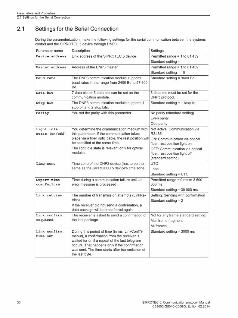
During the parameterization, make the following settings for the serial communication between the systemscontrol and the SIPROTEC 5 device through DNP3:
Parameter name Description SettingsDevice address Link address of the SIPROTEC 5 device Permitted range = 1 to 61 439
Standard setting = 1Master address Address of the DNP3 master Permitted range = 1 to 61 439
Standard setting = 10Baud rate The DNP3 communication module supports
baud rates in the range from 2400 Bd to 57 600Bd.
Standard setting = 9600 Bd
Data bit 7 data bits or 8 data bits can be set on thecommunication module.
8 data bits must be set for theDNP3 protocol.
Stop bit The DNP3 communication module supports 1stop bit and 2 stop bits.
Standard setting = 1 stop bit
Parity You set the parity with this parameter. No parity (standard setting)Even parityOdd parity
Light idlestate (on/off)
You determine the communication medium withthis parameter. If the communication takesplace via a fiber optic cable, the rest position willbe specified at the same time.The light idle state is relevant only for opticalmodules.
Not active: Communication viaRS485ON: Communication via opticalfiber; rest position light onOFF: Communication via opticalfiber; rest position light off(standard setting)
Time zone Time zone of the DNP3 device (has to be thesame as the SIPROTEC 5 device's time zone)
UTCLocalStandard setting = UTC
Superv.timecom.failure
Time during a communication failure until anerror message is processed
Permitted range = 0 ms to 3 600000 msStandard setting = 30 000 ms
Link retries The number of transmission attempts (LinkRe-tries)If the receiver did not send a confirmation, adata package will be transferred again.
Setting: Sending with confirmationStandard setting = 2
Link confirm.required
The receiver is asked to send a confirmation ofthe last package.
Not for any frame(standard setting)Multiframe fragmentAll frames
Link confirm.time-out
During this period of time (in ms; LinkConfTi-meout), a confirmation from the receiver iswaited for until a repeat of the last telegramoccurs. That happens only if the confirmationwas sent. The time starts after transmission ofthe last byte.
Standard setting = 3000 ms
2.1
Parameters and Properties2.1 Settings for the Serial Connection
30 SIPROTEC 5, Communication protocol, ManualC53000-G5040-C006-3, Edition 02.2014

Parameter name Description SettingsAppl. confirm.required
This parameter establishes when a confirmationof the application layer is required.
• If messages contain amendeddata, then a confirmation ofthe application layer isrequired.
• If telegrams from dividedpackages are not the comple-tion of a package, then aconfirmation of the applicationlayer is required (standardsetting).
Appl. confirm.time-out
The receiver waits a desired amount of time (inms) until the previous response is confirmed.If the confirmation of the application layer isused together with the link confirmation, thenmake sure that the time-out of the applicationlayer (ApplTimeout) is long enough in order toend all transmissions.The following formula describes this require-ment:
Standard setting = 9000 ms
Time sync.required
Time interval (in ms) until the internal displayTime required is set. This time interval isincluded in every response message. The timeinterval signals to the master to start a new timesynchronization with the device.
0 = The internal display is neverset.Standard setting = 60 000 ms
Time betw. sel.& switch.
A command must be selected and executed inthis time (in ms).
Standard setting = 10 000 ms
Enable unsoli-cited trans.
You determine whether unrequested transmis-sion is configured with this parameter.
Off = The non-requested transmis-sion is not configured and cannever be switched on from aconnected master (standardsetting).On = The non-requested transmis-sion is configured and must bemade possible after the 1st non-requested response from themaster.
Min. timetelegr. repet.
Minimum time of telegram repetition following acollision
Setting range: 0 ms to 100 msStandard setting = 50 ms
Max. timetelegr. repet.
Maximum time of telegram repetition following acollision
Setting range: 0 ms to 50 msStandard setting = 50 ms
Max. telegr.retries
Maximum number of telegram repetitionsfollowing a collision
Setting range: 1 to 200Standard setting = 5
The following parameters only make sense if the parameter Enable unsolicited trans. is set to On:
Unsolicitedevents class1
This parameter regulates a condition of the non-requested transmission for every class ofchanged events (class 1, class 2, and class 3).If the number of events per class correspondswith this value or exceeds this value, then anon-requested response will be sent.
Standard setting = 10
1This parameter is divided into class 1, 2, and 3
Parameters and Properties2.1 Settings for the Serial Connection
SIPROTEC 5, Communication protocol, Manual 31C53000-G5040-C006-3, Edition 02.2014
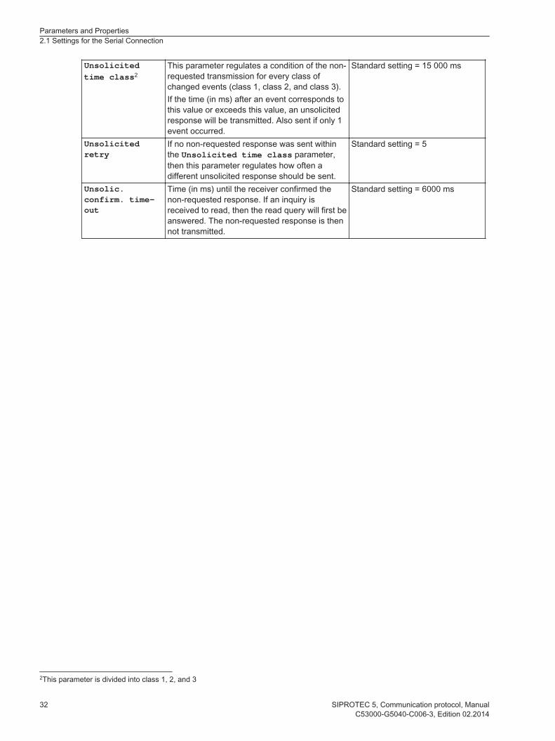
Unsolicitedtime class2
This parameter regulates a condition of the non-requested transmission for every class ofchanged events (class 1, class 2, and class 3).If the time (in ms) after an event corresponds tothis value or exceeds this value, an unsolicitedresponse will be transmitted. Also sent if only 1event occurred.
Standard setting = 15 000 ms
Unsolicitedretry
If no non-requested response was sent withinthe Unsolicited time class parameter,then this parameter regulates how often adifferent unsolicited response should be sent.
Standard setting = 5
Unsolic.confirm. time-out
Time (in ms) until the receiver confirmed thenon-requested response. If an inquiry isreceived to read, then the read query will first beanswered. The non-requested response is thennot transmitted.
Standard setting = 6000 ms
2This parameter is divided into class 1, 2, and 3
Parameters and Properties2.1 Settings for the Serial Connection
32 SIPROTEC 5, Communication protocol, ManualC53000-G5040-C006-3, Edition 02.2014
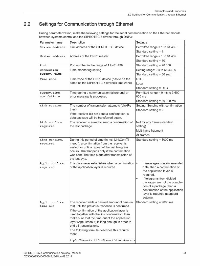
Settings for Communication through Ethernet
During parameterization, make the following settings for the serial communication on the Ethernet modulebetween systems control and the SIPROTEC 5 device through DNP3:
Parameter name Description SettingsDevice address Link address of the SIPROTEC 5 device Permitted range = 1 to 61 439
Standard setting = 1Master address Address of the DNP3 master Permitted range = 1 to 61 439
Standard setting = 10Port Port number in the range of 1 to 61 439 Standard setting = 20 000Connectionsuperv. time
Time monitoring setting Setting range: 0 s to 61 439 sStandard setting = 30 sec
Time zone Time zone of the DNP3 device (has to be thesame as the SIPROTEC 5 device's time zone)
UTCLocalStandard setting = UTC
Superv.timecom.failure
Time during a communication failure until anerror message is processed
Permitted range = 0 ms to 3 600000 msStandard setting = 30 000 ms
Link retries The number of transmission attempts (LinkRe-tries)If the receiver did not send a confirmation, adata package will be transferred again.
Setting: Sending with confirmationStandard setting = 2
Link confirm.required
The receiver is asked to send a confirmation ofthe last package.
Not for any frame (standardsetting)Multiframe fragmentAll frames
Link confirm.required
During this period of time (in ms; LinkConfTi-meout), a confirmation from the receiver iswaited for until a repeat of the last telegramoccurs. That happens only if the confirmationwas sent. The time starts after transmission ofthe last byte.
Standard setting = 3000 ms
Appl. confirm.required
This parameter establishes when a confirmationof the application layer is required.
• If messages contain amendeddata, then a confirmation ofthe application layer isrequired.
• If telegrams from dividedpackages are not the comple-tion of a package, then aconfirmation of the applicationlayer is required (standardsetting).
Appl. confirm.time-out
The receiver waits a desired amount of time (inms) until the previous response is confirmed.If the confirmation of the application layer isused together with the link confirmation, thenmake sure that the time-out of the applicationlayer (ApplTimeout) is long enough in order toend all transmissions.The following formula describes this require-ment:
Standard setting = 9000 ms
2.2
Parameters and Properties2.2 Settings for Communication through Ethernet
SIPROTEC 5, Communication protocol, Manual 33C53000-G5040-C006-3, Edition 02.2014
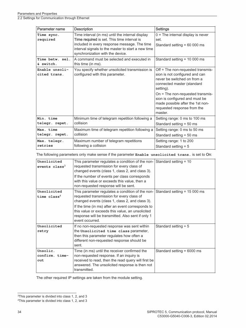
Parameter name Description SettingsTime sync.required
Time interval (in ms) until the internal displayTime required is set. This time interval isincluded in every response message. The timeinterval signals to the master to start a new timesynchronization with the device.
0 = The internal display is neverset.Standard setting = 60 000 ms
Time betw. sel.& switch.
A command must be selected and executed inthis time (in ms).
Standard setting = 10 000 ms
Enable unsoli-cited trans.
You specify whether unsolicited transmission isconfigured with this parameter.
Off = The non-requested transmis-sion is not configured and cannever be switched on from aconnected master (standardsetting).On = The non-requested transmis-sion is configured and must bemade possible after the 1st non-requested response from themaster.
Min. timetelegr. repet.
Minimum time of telegram repetition following acollision
Setting range: 0 ms to 100 msStandard setting = 50 ms
Max. timetelegr. repet.
Maximum time of telegram repetition following acollision
Setting range: 0 ms to 50 msStandard setting = 50 ms
Max. telegr.retries
Maximum number of telegram repetitionsfollowing a collision
Setting range: 1 to 200Standard setting = 5
The following parameters only make sense if the parameter Enable unsolicited trans. is set to On:
Unsolicitedevents class3
This parameter regulates a condition of the non-requested transmission for every class ofchanged events (class 1, class 2, and class 3).If the number of events per class correspondswith this value or exceeds this value, then anon-requested response will be sent.
Standard setting = 10
Unsolicitedtime class4
This parameter regulates a condition of the non-requested transmission for every class ofchanged events (class 1, class 2, and class 3).If the time (in ms) after an event corresponds tothis value or exceeds this value, an unsolicitedresponse will be transmitted. Also sent if only 1event occurred.
Standard setting = 15 000 ms
Unsolicitedretry
If no non-requested response was sent withinthe Unsolicited time class parameter,then this parameter regulates how often adifferent non-requested response should besent.
Standard setting = 5
Unsolic.confirm. time-out
Time (in ms) until the receiver confirmed thenon-requested response. If an inquiry isreceived to read, then the read query will first beanswered. The unsolicited response is then nottransmitted.
Standard setting = 6000 ms
The other required IP settings are taken from the module setting.
3This parameter is divided into class 1, 2, and 34This parameter is divided into class 1, 2, and 3
Parameters and Properties2.2 Settings for Communication through Ethernet
34 SIPROTEC 5, Communication protocol, ManualC53000-G5040-C006-3, Edition 02.2014

[scethset-060511-01.tif, 1, en_US]
Figure 2-1 IP Settings in the Module Setting
Parameters and Properties2.2 Settings for Communication through Ethernet
SIPROTEC 5, Communication protocol, Manual 35C53000-G5040-C006-3, Edition 02.2014

36 SIPROTEC 5, Communication protocol, ManualC53000-G5040-C006-3, Edition 02.2014

Setting Parameters in DIGSI 5
3.1 Communication-Module Selection 38
3.2 Communication-Module Configuration 393.3 Signals to the Communication Modules 42
3.4 Select Mapping 433.5 Adapting Mappings 44
3.6 Copying Mappings 523.7 Exporting Mappings 53
3.8 Changing Mappings 543.9 Time Synchronization 55
3
SIPROTEC 5, Communication protocol, Manual 37C53000-G5040-C006-3, Edition 02.2014
Communication-Module Selection
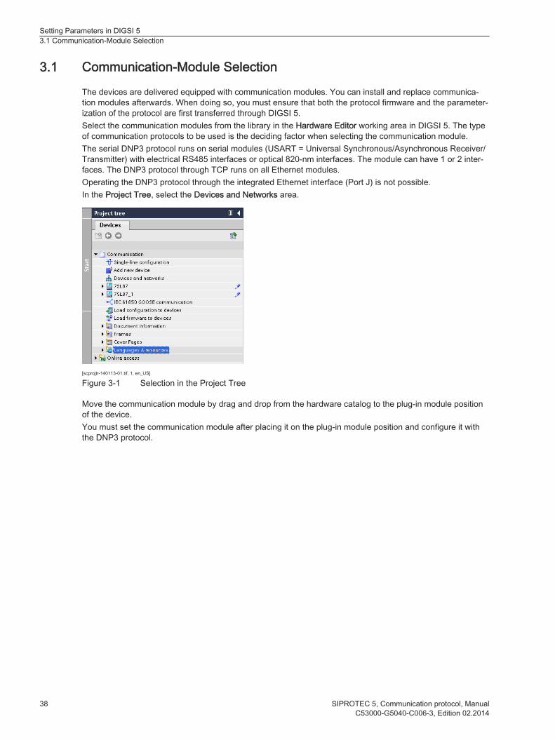
The devices are delivered equipped with communication modules. You can install and replace communica-tion modules afterwards. When doing so, you must ensure that both the protocol firmware and the parameter-ization of the protocol are first transferred through DIGSI 5.Select the communication modules from the library in the Hardware Editor working area in DIGSI 5. The typeof communication protocols to be used is the deciding factor when selecting the communication module.The serial DNP3 protocol runs on serial modules (USART = Universal Synchronous/Asynchronous Receiver/Transmitter) with electrical RS485 interfaces or optical 820-nm interfaces. The module can have 1 or 2 inter-faces. The DNP3 protocol through TCP runs on all Ethernet modules.Operating the DNP3 protocol through the integrated Ethernet interface (Port J) is not possible.In the Project Tree, select the Devices and Networks area.
[scprojtr-140113-01.tif, 1, en_US]
Figure 3-1 Selection in the Project Tree
Move the communication module by drag and drop from the hardware catalog to the plug-in module positionof the device.You must set the communication module after placing it on the plug-in module position and configure it withthe DNP3 protocol.
3.1
Setting Parameters in DIGSI 53.1 Communication-Module Selection
38 SIPROTEC 5, Communication protocol, ManualC53000-G5040-C006-3, Edition 02.2014
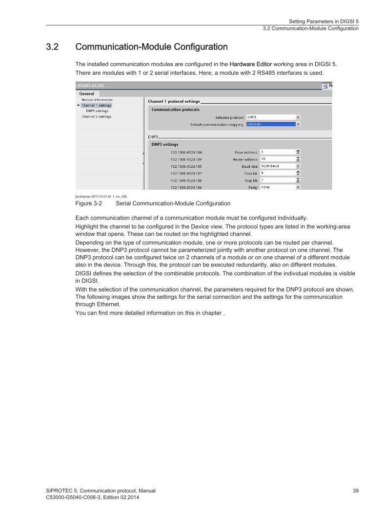
Communication-Module Configuration
The installed communication modules are configured in the Hardware Editor working area in DIGSI 5.There are modules with 1 or 2 serial interfaces. Here, a module with 2 RS485 interfaces is used.
[scdnpmpr-251110-01.tif, 1, en_US]
Figure 3-2 Serial Communication-Module Configuration
Each communication channel of a communication module must be configured individually.Highlight the channel to be configured in the Device view. The protocol types are listed in the working-areawindow that opens. These can be routed on the highlighted channel.Depending on the type of communication module, one or more protocols can be routed per channel.However, the DNP3 protocol cannot be parameterized jointly with another protocol on one channel. TheDNP3 protocol can be configured twice on 2 channels of a module or on one channel of a different modulealso in the device. Through this, the protocol can be executed redundantly, also on different modules.DIGSI defines the selection of the combinable protocols. The combination of the individual modules is visiblein DIGSI.With the selection of the communication channel, the parameters required for the DNP3 protocol are shown.The following images show the settings for the serial connection and the settings for the communicationthrough Ethernet.You can find more detailed information on this in chapter .
3.2
Setting Parameters in DIGSI 53.2 Communication-Module Configuration
SIPROTEC 5, Communication protocol, Manual 39C53000-G5040-C006-3, Edition 02.2014

[sc DNP3 settings serial communication 050314.tif, 1, en_US]
Figure 3-3 Settings for the Serial Connection
Setting Parameters in DIGSI 53.2 Communication-Module Configuration
40 SIPROTEC 5, Communication protocol, ManualC53000-G5040-C006-3, Edition 02.2014

[sc DNP3 Ethernet settings part 1 050314.tif, 1, en_US]
Figure 3-4 Settings for Communication through Ethernet - Part 1
[sc DNP3 Ethernet settings part 2 050314, 1, en_US]
Figure 3-5 Settings for Communication through Ethernet - Part 2
Setting Parameters in DIGSI 53.2 Communication-Module Configuration
SIPROTEC 5, Communication protocol, Manual 41C53000-G5040-C006-3, Edition 02.2014

Signals to the Communication Modules
Description of the Signals to the Communication Modules
There are different signals for each communication module:• Channel Live
The signal Channel Live displays the data flow. Therefore, the signal indicates that the communicationservice is transmitting and receiving data on the module.Consider that multiple services can run in parallel on one Ethernet module. The representation is definedin the standard IEC 61850, Edition 2.
• Module readyThe signal Module ready indicates that the module has started and the protocol applications are started.You can reallocate this signal, for example, LED, log, or message. Then, you will recognize whether theIEC 61850 services are stared on an Ethernet module, for example GOOSE. and are working correctly.
iiNOTE
Starting the module can take some time.
• HealthThe signal Health indicates the state of the module. The following 3 states can occur in this case:– Okay
Module OK indicates, that the module is working.
– WarningThis state is not used.
– AlarmThe state Alarm is set when there is a failure of the module.
Each protocol application has a Health node. If a protocol has problems at startup, for example, missingparameters, no mapping, no hardware support, the status is set to Alarm. An alarm in a protocol causes analarm of the module.
3.3
Setting Parameters in DIGSI 53.3 Signals to the Communication Modules
42 SIPROTEC 5, Communication protocol, ManualC53000-G5040-C006-3, Edition 02.2014

Select Mapping
With the selection of the protocol on a channel, the mapping for the DNP3 protocol is also determined. Theroutings defined in the mapping are displayed in the Communication Data Mapping Editor for each channel.Standard mapping contains prioritized indications, measured values, and commands.A standard mapping is provided for the DNP3 protocol. The standard mapping contains the routings, whichare specified by the DNP3 protocol.Routings in the communication matrix are also possible without selecting an existing mapping file.
[sc mapping selection 050314.tif, 1, en_US]
Figure 3-6 Select Mapping
iiNOTE
After instantiating the protection functions, assign the standard mapping as the second to last step. Afterthis, you must parameterize the time synchronization.Retrospectively created data objects are not automatically included in an existing mapping.
3.4
Setting Parameters in DIGSI 53.4 Select Mapping
SIPROTEC 5, Communication protocol, Manual 43C53000-G5040-C006-3, Edition 02.2014
Adapting Mappings
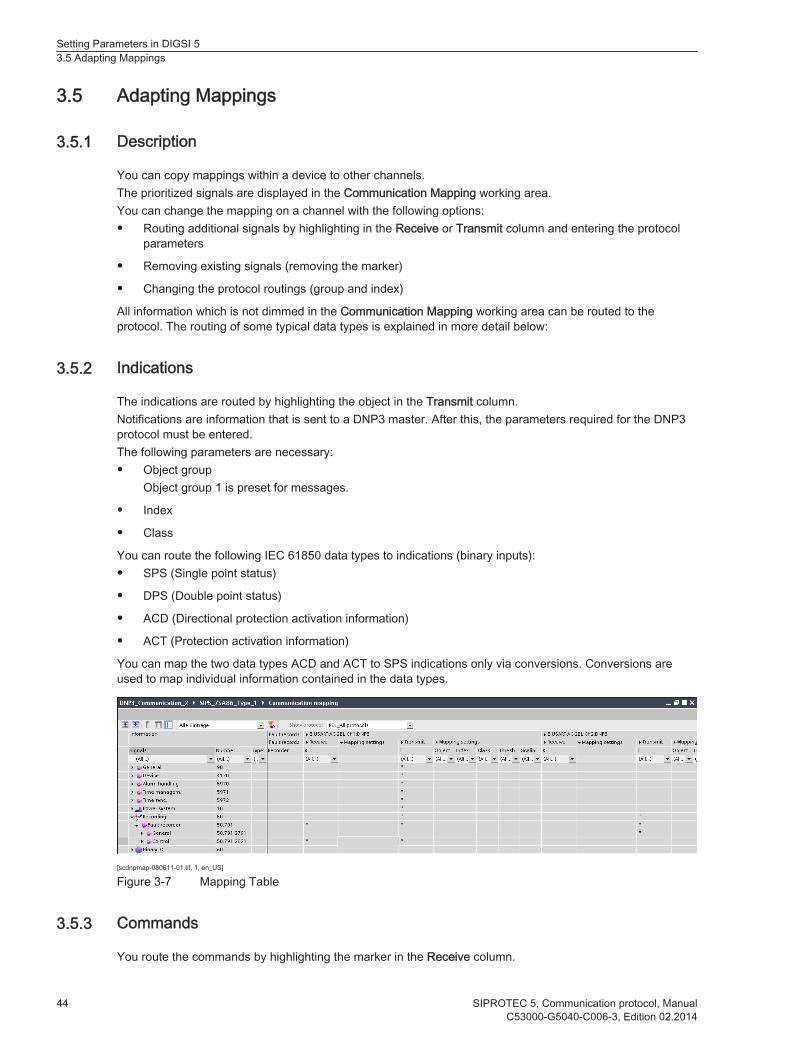
Description
You can copy mappings within a device to other channels.The prioritized signals are displayed in the Communication Mapping working area.You can change the mapping on a channel with the following options:• Routing additional signals by highlighting in the Receive or Transmit column and entering the protocol
parameters
• Removing existing signals (removing the marker)
• Changing the protocol routings (group and index)
All information which is not dimmed in the Communication Mapping working area can be routed to theprotocol. The routing of some typical data types is explained in more detail below:
Indications
The indications are routed by highlighting the object in the Transmit column.Notifications are information that is sent to a DNP3 master. After this, the parameters required for the DNP3protocol must be entered.The following parameters are necessary:• Object group
Object group 1 is preset for messages.
• Index
• Class
You can route the following IEC 61850 data types to indications (binary inputs):• SPS (Single point status)
• DPS (Double point status)
• ACD (Directional protection activation information)
• ACT (Protection activation information)
You can map the two data types ACD and ACT to SPS indications only via conversions. Conversions areused to map individual information contained in the data types.
[scdnpmap-080611-01.tif, 1, en_US]
Figure 3-7 Mapping Table
Commands
You route the commands by highlighting the marker in the Receive column.
3.5
3.5.1
3.5.2
3.5.3
Setting Parameters in DIGSI 53.5 Adapting Mappings
44 SIPROTEC 5, Communication protocol, ManualC53000-G5040-C006-3, Edition 02.2014

The mapping of the commands occurs like the mapping of messages. Here, object group 12 is preset.
iiNOTE
For commands, the DNP3 protocol allows both direct operate and a select before switching. The type ofswitching is configured by the switching object; this means the protocol takes over the mode that is para-meterized in the switching object.
You can route the following IEC 61850 data types to commands (binary output):• SPC (Single-Point Control)
• DPC (Double-Point Control)
If a command status signal should be mapped or if it is preset through the control model, the status signalfrom the command will be parameterized in the same line under the Transmit column.
[scmapctr-060511-01.tif, 1, en_US]
Figure 3-8 Mapping Commands
Supported Control Models
The SIPROTEC 5 device supports the control models (according to IEC 61850):• Direct with normal security
• SBO (Select before operate) with normal security
• Direct with enhanced security
• SBO with enhanced security
Measured Values
The measured values are routed by highlighting the object in the Transmit column. After this, you must enterthe parameters required for the protocol.The primary values are carried over from the Master.The following parameters are necessary:• Group
• Index
• Scaling
3.5.4
Setting Parameters in DIGSI 53.5 Adapting Mappings
SIPROTEC 5, Communication protocol, Manual 45C53000-G5040-C006-3, Edition 02.2014

• Object
• Class
[scmmednp-251110-01.tif, 1, en_US]
Figure 3-9 Mapping of Measured Values
Scaling Measured Values
The measured values between the SIPROTEC 5 device and the DNP3 master are transferred as integervalues in 16-bit or 32-bit format. 16 bits correspond with a range from 0 to 65 535; 32 bits correspond with arange from 0 to 4 294 967 295.You can find more detailed information on this in chapter 3.4 Select Mapping.The measured values are available in the SIPROTEC 5 device in floating-point format, related to the parame-terized rated variables of the primary system in percentage.
Converting Measured Values
Before the transfer of a measured value through DNP3, the measured values must be converted in theSIPROTEC 5 device. The measured values are scaled.The scaling of a measured value determines the form of transmission. These forms of transmission are:• Value type
• Scaling factor
Scaling Factor
The measured value is multiplied in the SIPROTEC 5 device by the scaling factor. The measured values arethen changed into integer measured values (for DNP3) in the floating-point procedure.Through multiplication with a multiple of 10, decimal points can also be transferred into integer measuredvalues.
Calculation Formula for Integer Measured Values
The following conditions must be met for the calculation:• The floating-point number (measured valueFloat) is available in the corresponding value type (primary or
secondary value).
• The floating-point number (measured valueFloat) is available as a percent value.
The integer measured value (measured valueInteger) for the transmission through DNP3 is calculatedaccording to the following formula:
Setting Parameters in DIGSI 53.5 Adapting Mappings
46 SIPROTEC 5, Communication protocol, ManualC53000-G5040-C006-3, Edition 02.2014

[fomwintr-230310-01.tif, 1, en_US]
Setting the Measured-Value Threshold
In the measured-value processing via DNP3, there are measured-value thresholds you can set. The meas-ured-value threshold for the individual measured values is not set in the communication matrix but centrally inthe routing matrix. The following measured-value thresholds are preset:
Measured-Value Threshold Setting Valuedb5 for values from type frequencies:(neutral zone for values of the type Frequencies)
0,1 %
db for values from type voltages:(neutral zone for values of the type Voltages)
2 %
db for values from type currents:(neutral zone for values of the type Currents)
10 %
db for values from type power:(neutral zone for values of the type Power)
10 %
db for values from type all others:(neutral zone for values of the type all others)
10 %
dbAng for values from all type angles:(neutral zone dbAng for values of all type angles)
1 %
This setting value applies to the currently measured value. If, for instance, the measured value is 110 kV andthe preset value is 2 %, then the measured value will be transmitted in the event that the measured valueschanges by 2.2 kV.
Counter Values
All of the IEC 61850 objects of type BCR (Binary Counter Reading) in the SIPROTEC 5 device can be routedto counter values (object type 20). The routing takes place by marking the object in the Transmit column.
An Example Calculation for a Measured Performance Value
The following parameters are included in the parameter set:• Rated operating voltage of the primary system = 12.00 kV
• Rated operating current of the primary system = 100 A
The measured performance value is calculated based on the following formula:
[foleismw-121109-01.tif, 1, en_US]
In the SIPROTEC 5 device, this measured performance value is stated from 0.00 MW to 9.99 MW, that iswith 2 relevant decimal points.Siemens recommends a scaling factor of 100 for the transmission as an integer measured value throughDNP3. With this, a value from 0 to 999 is transferred to the master.If the scaling factor is less than 100, then important information about the decimal points is lost during thetransmission. A scaling factor larger than 100 does not create any precise information. The accuracy is onlysimulated, but really non-existent. Thus, with a scaling factor of 100 there is an interpretation of the integermeasured value (measured valueInteger) through DNP3 with: ±32 768. This corresponds with a value of ±327.68 MW.
3.5.5
5db = dead band
Setting Parameters in DIGSI 53.5 Adapting Mappings
SIPROTEC 5, Communication protocol, Manual 47C53000-G5040-C006-3, Edition 02.2014
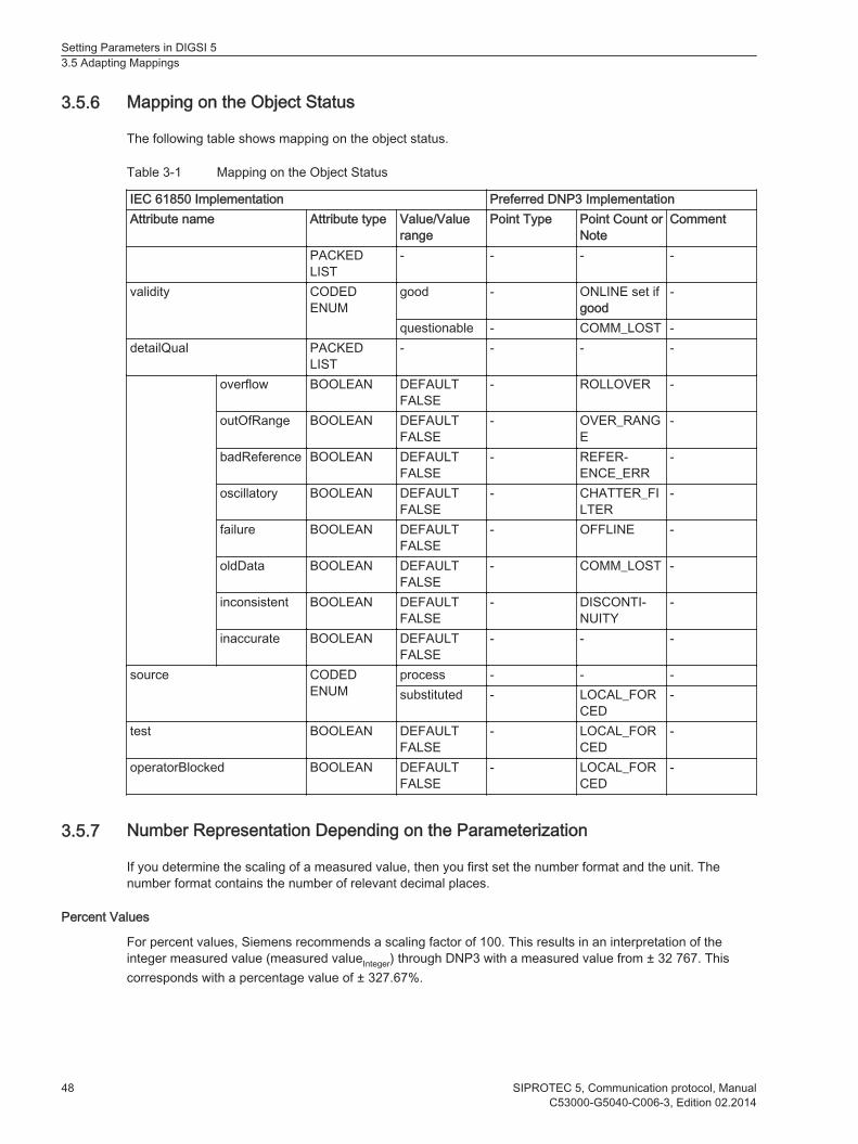
Mapping on the Object Status
The following table shows mapping on the object status.
Table 3-1 Mapping on the Object Status
IEC 61850 Implementation Preferred DNP3 ImplementationAttribute name Attribute type Value/Value
rangePoint Type Point Count or
NoteComment
PACKEDLIST
- - - -
validity CODEDENUM
good - ONLINE set ifgood
-
questionable - COMM_LOST -detailQual PACKED
LIST- - - -
overflow BOOLEAN DEFAULTFALSE
- ROLLOVER -
outOfRange BOOLEAN DEFAULTFALSE
- OVER_RANGE
-
badReference BOOLEAN DEFAULTFALSE
- REFER-ENCE_ERR
-
oscillatory BOOLEAN DEFAULTFALSE
- CHATTER_FILTER
-
failure BOOLEAN DEFAULTFALSE
- OFFLINE -
oldData BOOLEAN DEFAULTFALSE
- COMM_LOST -
inconsistent BOOLEAN DEFAULTFALSE
- DISCONTI-NUITY
-
inaccurate BOOLEAN DEFAULTFALSE
- - -
source CODEDENUM
process - - -substituted - LOCAL_FOR
CED-
test BOOLEAN DEFAULTFALSE
- LOCAL_FORCED
-
operatorBlocked BOOLEAN DEFAULTFALSE
- LOCAL_FORCED
-
Number Representation Depending on the Parameterization
If you determine the scaling of a measured value, then you first set the number format and the unit. Thenumber format contains the number of relevant decimal places.
Percent Values
For percent values, Siemens recommends a scaling factor of 100. This results in an interpretation of theinteger measured value (measured valueInteger) through DNP3 with a measured value from ± 32 767. Thiscorresponds with a percentage value of ± 327.67%.
3.5.6
3.5.7
Setting Parameters in DIGSI 53.5 Adapting Mappings
48 SIPROTEC 5, Communication protocol, ManualC53000-G5040-C006-3, Edition 02.2014

Secondary Values
If, for example, the values from the transducer inputs are specified in mA, then the transmission of a meas-ured value as a secondary value makes sense.The number of significant decimal points depends on the system and transducer data.
Primary Values
The position of the decimal point and the respective unit are determined for primary values based on theparameterized rated variables of the primary system.
Copying Mapping Rows
You can highlight and copy individual mapping rows, columns or cells. To cut, copy and paste, use either thebuttons in the toolbar or right-click on the corresponding row, column or cell.
[diiconcp-240111-01.tif, 1, --_--]
Figure 3-10 Cut, Copy and Paste Buttons
[scrowcpa-250111-01.tif, 1, en_US]
Figure 3-11 Copying Individual Mapping Rows
3.5.8
Setting Parameters in DIGSI 53.5 Adapting Mappings
SIPROTEC 5, Communication protocol, Manual 49C53000-G5040-C006-3, Edition 02.2014

[sccopaco-240111-01.tif, 1, en_US]
Figure 3-12 Copying Columns
[sccopacl-240111-01.tif, 1, en_US]
Figure 3-13 Copying Cells
You can also highlight, copy and paste entire ranges.
Setting Parameters in DIGSI 53.5 Adapting Mappings
50 SIPROTEC 5, Communication protocol, ManualC53000-G5040-C006-3, Edition 02.2014

[sccpsear-240111-01.tif, 1, en_US]
Figure 3-14 Copying a Range
[scmappas-250111-01.tif, 1, en_US]
Figure 3-15 Pasting a Copied Range
Setting Parameters in DIGSI 53.5 Adapting Mappings
SIPROTEC 5, Communication protocol, Manual 51C53000-G5040-C006-3, Edition 02.2014
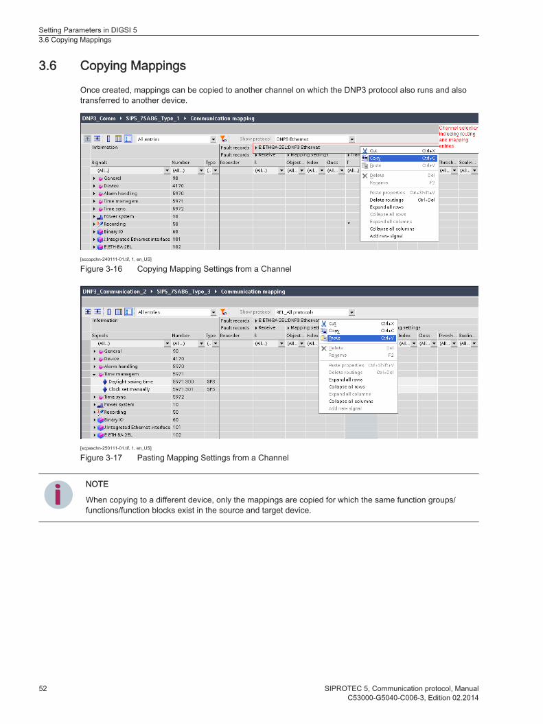
Copying Mappings
Once created, mappings can be copied to another channel on which the DNP3 protocol also runs and alsotransferred to another device.
[sccopchn-240111-01.tif, 1, en_US]
Figure 3-16 Copying Mapping Settings from a Channel
[scpaschn-250111-01.tif, 1, en_US]
Figure 3-17 Pasting Mapping Settings from a Channel
iiNOTE
When copying to a different device, only the mappings are copied for which the same function groups/functions/function blocks exist in the source and target device.
3.6
Setting Parameters in DIGSI 53.6 Copying Mappings
52 SIPROTEC 5, Communication protocol, ManualC53000-G5040-C006-3, Edition 02.2014

Exporting Mappings
Once created, mappings can be exported to a data file. The master/client configuration software can beconfigured using this export.The Siemens substation control unit parameterization software can import this file directly.To export a device mapping file, select the device and click the Project menu. Then select the menu itemExport. The Export dialog appears.You can select from the following data formats for the export:• Device-dependent data formats, for example, TEAX, DEX5 etc.
• Protocol-dependent data formatsFor every protocol for which parameters are set, there is a special format with the appropriate file exten-sion DigT103 or DigDNP.
Finally, click Export.
[scmapexp-280113-01.tif, 1, en_US]
Figure 3-18 Exporting Mapping to a Data File
3.7
Setting Parameters in DIGSI 53.7 Exporting Mappings
SIPROTEC 5, Communication protocol, Manual 53C53000-G5040-C006-3, Edition 02.2014

Changing Mappings
iiNOTE
If you change a standard mapping, all existing mapping information will be lost. DIGSI shows a messagetherefore.
[scchgmap-060511-01.tif, 1, en_US]
Figure 3-19 Message in DIGSI
3.8
Setting Parameters in DIGSI 53.8 Changing Mappings
54 SIPROTEC 5, Communication protocol, ManualC53000-G5040-C006-3, Edition 02.2014
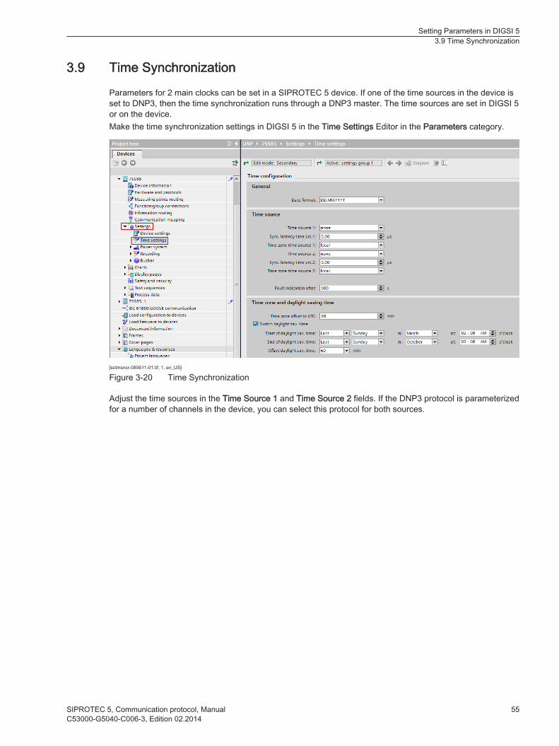
Time Synchronization
Parameters for 2 main clocks can be set in a SIPROTEC 5 device. If one of the time sources in the device isset to DNP3, then the time synchronization runs through a DNP3 master. The time sources are set in DIGSI 5or on the device.Make the time synchronization settings in DIGSI 5 in the Time Settings Editor in the Parameters category.
[sctmsncr-080611-01.tif, 1, en_US]
Figure 3-20 Time Synchronization
Adjust the time sources in the Time Source 1 and Time Source 2 fields. If the DNP3 protocol is parameterizedfor a number of channels in the device, you can select this protocol for both sources.
3.9
Setting Parameters in DIGSI 53.9 Time Synchronization
SIPROTEC 5, Communication protocol, Manual 55C53000-G5040-C006-3, Edition 02.2014

[sctsrdnp-251110-01.tif, 1, en_US]
Figure 3-21 Setting the Time Sources
If the time source in the device is set to DNP3, then the time synchronization can run through a DNP3 master.The time source is set in DIGSI 5 or on the device.In the DNP3 protocol, you have the possibility to execute time synchronization with local time or with UTC.The selection occurs in DIGSI 5 with the parameters designated for this. The time zones for the time synchro-nization parameterization and in the DNP3 protocol have to be identical if set to local.The SIPROTEC 5 device monitors the continuous reception of the time synchronization telegram. After expiryof the set time in Error display after: a time synchronization error message is generated. The faulty time in thedevice is also displayed. This time fault remains until a new time synchronization telegram is received.
iiNOTE
During parameterization, the time in Time synchronization required must be greater than the synchroniza-tion interval of the DNP3 master. Siemens recommends a synchronization interval of 1 min. However, themaster can also send the telegram every 5 min or 10 min. When setting the interval to 1 min, the time inthe device is set to invalid if no synchronization telegram is received in 2 min. In the meantime, the devicesets the clock via the internal quartz-crystal oscillator.
Setting Parameters in DIGSI 53.9 Time Synchronization
56 SIPROTEC 5, Communication protocol, ManualC53000-G5040-C006-3, Edition 02.2014

Communication Modules
4.1 Overview 58
4.2 Communication Applications of the Plug-In Module 624.3 Serial Communication Modules for Short Distances 64
4.4 Ethernet Modules 684.5 Configuration, Installation, Replacement 71
4
SIPROTEC 5, Communication protocol, Manual 57C53000-G5040-C006-3, Edition 02.2014

Overview
SIPROTEC devices can be ordered with factory-installed communication modules. The communicationmodules can also be installed and replaced in the SIPROTEC devices afterwards. You do not have to openthe device for this.
iiNOTE
The communication modules available for reordering are not preconfigured. Use DIGSI 5 to carry out thefunctional adjustment to the required protocol application.
The communication modules can be installed in the base module or the 1/3 module and in the expansionmodule with the plug-in module assembly CB202. A maximum of 2 communication modules each can beinstalled. You can use only one CB202 in the device.The plug-in module assembly CB202 is a module with an integrated power supply.The CB202 plug-in module assembly PCB communicates with the base module via a special connectingcable. This connecting cable (CAT 5 FTP patch cable) is always included in the scope of delivery of theCB202 assembly or the devices containing the CB202 assembly and need not be ordered separately.Ensure that you route the communication lines separately from network circuits.
[dwcm201p-030211-01.tif, 1, --_--]
Figure 4-1 Plug-In Module Positions and Communication Terminals in the Base Module, with ModularDevices
(1) Time synchronization G(2) Plug-in module position E(3) Detached on-site operation panel H(4) Plug-in module position F(5) Integrated Ethernet interface J
4.1
Communication Modules4.1 Overview
58 SIPROTEC 5, Communication protocol, ManualC53000-G5040-C006-3, Edition 02.2014
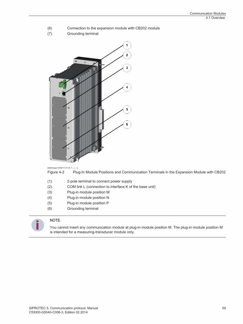
(6) Connection to the expansion module with CB202 module(7) Grounding terminal
[dwlmnppo-030211-01.tif, 1, --_--]
Figure 4-2 Plug-In Module Positions and Communication Terminals in the Expansion Module with CB202
(1) 2-pole terminal to connect power supply(2) COM link L (connection to interface K of the base unit)(3) Plug-in module position M(4) Plug-in module position N(5) Plug-in module position P(6) Grounding terminal
iiNOTE
You cannot insert any communication module at plug-in module position M. The plug-in module position Mis intended for a measuring-transducer module only.
Communication Modules4.1 Overview
SIPROTEC 5, Communication protocol, Manual 59C53000-G5040-C006-3, Edition 02.2014
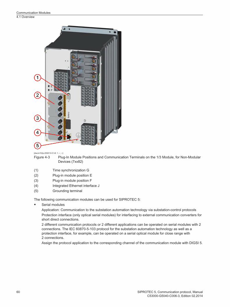
[dwcm102p-250613-01.tif, 1, --_--]
Figure 4-3 Plug-In Module Positions and Communication Terminals on the 1/3 Module, for Non-ModularDevices (7xx82)
(1) Time synchronization G(2) Plug-in module position E(3) Plug-in module position F(4) Integrated Ethernet interface J(5) Grounding terminal
The following communication modules can be used for SIPROTEC 5:• Serial modules
Application: Communication to the substation automation technology via substation-control protocolsProtection interface (only optical serial modules) for interfacing to external communication converters forshort direct connections.2 different communication protocols or 2 different applications can be operated on serial modules with 2connections. The IEC 60870-5-103 protocol for the substation automation technology as well as aprotection interface, for example, can be operated on a serial optical module for close range with2 connections.Assign the protocol application to the corresponding channel of the communication module with DIGSI 5.
Communication Modules4.1 Overview
60 SIPROTEC 5, Communication protocol, ManualC53000-G5040-C006-3, Edition 02.2014

• Ethernet ModulesApplication: Ethernet-based communication to the substation automation technology via substation-control protocols (for example, IEC 61850 and DNP3)– Secure communication to DIGSI 5
– Communication between the devices (IEC 61850-GOOSE)
– Synchrophasor protocol
The modules can be operated with or without an integrated switch.
• Long-distance modulesApplication: Direct protection interface communication over long distances using multimode or single-mode optical fibers.
The designation of the modules corresponds to the following scheme, which is typically explained with themodule USART-AB-1EL. The module designation consists of 3 blocks.
1st block Type of moduleUSART = Serial module for short or long distanceETH = Ethernet module
2nd block Unique code for the module in the product code of the deviceThe code consists of 2 letters.
3rd block Number and physical design of the connections1 = 1 connection (1 channel)2 = 2 connections (2 channels)EL = Electrical connectionFO = Fiber-optic connectionLDFO = Long-distance transmission via fiber-optic cables
Communication Modules4.1 Overview
SIPROTEC 5, Communication protocol, Manual 61C53000-G5040-C006-3, Edition 02.2014

Communication Applications of the Plug-In Module
You can find information on communication applications for the plug-in modules in the following tables.
Table 4-1 Communication Applications and Plug-in Modules
Port or plug-in module
Fron
t int
erfa
ce
Fron
t int
erfa
ce P
ort G
: Tim
e Sy
nchr
oniz
atio
n
Port
J: In
tegr
ated
Eth
erne
t
Mod
ule
Type
: USA
RT-
AB-1
EL
Mod
ule
Type
: USA
RT-
AC-2
EL
Mod
ule
Type
: USA
RT-
AD-1
FO
Mod
ule
Type
: USA
RT-
AE-2
FO
Mod
ule
Type
: ETH
-BA-
2EL
Mod
ule
Type
: ETH
-BB-
2FO
Physical ConnectionUSB-A ●D-Sub 9 socket ●1 x electrical Ethernet 10/100 Mbit/s, RJ45 ●1 x electrical serial RS485, RJ45 ●2 x electrical serial RS485, RJ45 ●1 x optical serial, 820 nm, ST connector, 1.5 km over62.5/125 μm multimode optical fiber
●
2 x optical serial, 820 nm, ST connector, 1,5 km over62.5/125 μm multimode optical fiber
●
2 x electrical Ethernet 10/100 Mbit/s, RJ45, 20 m ●2 x optical Ethernet 100 Mbit/s, 1300 nm, LC duplexplug, 2 km over 50/125 μm or 62.5/125 μm multimodeoptical fiber
●
ApplicationsDIGSI 5 protocol X – X – – – – X XIRIG-B, DCF77, highly accurate 1-s pulse – X – – – – – – –IEC 61850-8-1 server (incl. GOOSE, reporting to 6clients)
– – – – – – – X X
IEC 61850-8-1 server (without GOOSE, reporting to 6clients)
– – X – – – – – –
IEC 60870-5-103 (extended) – – – X X X X – –DNP3 serial – – – X X X X – –DNP3 over Ethernet – – – – – – – X XSynchrophasor (IEEE C37.118 – IP)6 – – – – – – – X XProtection interface (Sync. HDLC, IEEE C37.94)7 – – – – – X X – –Additional Ethernet Logs and ServicesDHCP (automatic IP configuration), DCP – – X – – – – X X
4.2
6Additional modules for the protection interface: see next table7In process
Communication Modules4.2 Communication Applications of the Plug-In Module
62 SIPROTEC 5, Communication protocol, ManualC53000-G5040-C006-3, Edition 02.2014

Port or plug-in module
Fron
t int
erfa
ce
Fron
t int
erfa
ce P
ort G
: Tim
e Sy
nchr
oniz
atio
n
Port
J: In
tegr
ated
Eth
erne
t
Mod
ule
Type
: USA
RT-
AB-1
EL
Mod
ule
Type
: USA
RT-
AC-2
EL
Mod
ule
Type
: USA
RT-
AD-1
FO
Mod
ule
Type
: USA
RT-
AE-2
FO
Mod
ule
Type
: ETH
-BA-
2EL
Mod
ule
Type
: ETH
-BB-
2FO
RSTP (Ethernet ring redundancy) – – – – – – – X XSNTP (time synchronization over Ethernet) – – X – – – – X XSNMP V3 (network management protocol) – – – – – – – X X
iiNOTE
The USART and ETH plug-in module types may be used in slots E and F in the base module as well as inslots N and P in the CB202 expansion module. They are not intended for use in slot M in the CB202expansion module.
Communication Modules4.2 Communication Applications of the Plug-In Module
SIPROTEC 5, Communication protocol, Manual 63C53000-G5040-C006-3, Edition 02.2014

Serial Communication Modules for Short Distances
Special Features of the Serial Electrical Modules
The serial electrical modules are equipped with RJ45 connections. These are not Ethernet connections. Theserial signals of the RS485 interface are routed to the RJ45 connections (see following figure).
[dwrj45pb-030211-01.tif, 1, en_US]
Figure 4-4 RJ45 Terminals for the Serial Signals of the RS485 Interface
Cabling Examples of Devices with Serial Electrical Modules
Serial electrical RS485 connections of devices in the SIPROTEC 5 series can be cabled with low-costEthernet patch cables. Special bus cables and adaptors are not needed. Pay attention to the following note ifyou include devices from the SIPROTEC 4 series in the connection.
iiNOTE
The RS485 interface in devices of the SIPROTEC 4 series is a D-Sub 9 connection with a connectedterminal resistor.If you connect devices from the SIPROTEC 5 series with devices from the SIPROTEC 4 series, then usean Y adaptor with the order designation 7XV5103-2BA00. Complete the connection on the last device witha terminal resistor. For the SIPROTEC 5 device, use a terminal resistor with the order designation RS485terminator 7XV5103-5BA00.
[dwserma1-030211-04.tif, 1, en_US]
Figure 4-5 Communication with a Single Master using an RS485 Bus
The preceding figure shows the cabling using the new RJ45 sockets in a simplified format. The serial RS485bus can be extended by simply connecting Ethernet patch cables from device to device.
4.3
4.3.1
Communication Modules4.3 Serial Communication Modules for Short Distances
64 SIPROTEC 5, Communication protocol, ManualC53000-G5040-C006-3, Edition 02.2014
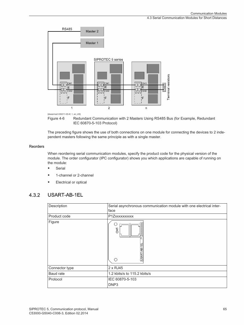
[dwserma2-030211-05.tif, 1, en_US]
Figure 4-6 Redundant Communication with 2 Masters Using RS485 Bus (for Example, RedundantIEC 60870-5-103 Protocol)
The preceding figure shows the use of both connections on one module for connecting the devices to 2 inde-pendent masters following the same principle as with a single master.
Reorders
When reordering serial communication modules, specify the product code for the physical version of themodule. The order configurator (IPC configurator) shows you which applications are capable of running onthe module:• Serial
• 1-channel or 2-channel
• Electrical or optical
USART-AB-1EL
Description Serial asynchronous communication module with one electrical inter-face
Product code P1ZxxxxxxxxxxFigure
Connector type 2 x RJ45Baud rate 1.2 kbits/s to 115.2 kbits/sProtocol IEC 60870-5-103
DNP3
4.3.2
Communication Modules4.3 Serial Communication Modules for Short Distances
SIPROTEC 5, Communication protocol, Manual 65C53000-G5040-C006-3, Edition 02.2014

USART-AC-2EL
Description Serial asynchronous communication module with 2 independent elec-trical interfaces
Product code P1ZxxxxxxxxxxFigure
Connector type 4 x RJ45Baud rate 1.2 kbits/s to 115.2 kbits/sFor 1 or 2 protocols or applications(1 application per connection)
IEC 60870-5-103DNP3
USART-AD-1FO
Description Serial asynchronous or synchronous communication module with oneindependent optical interface
Product code P1ZxxxxxxxxxxFigure
Connector type 2 x STWavelength λ = 820 nmBaud rate Asynchronous: 1.2 kbits/s to 115.2 kbits/s
Synchronous: 64 kBit/s to 2 Mbit/sFor 1 protocol or application IEC 60870-5-103
DNP3Protection interface communication
Max. distance 2 km when using an optical fiber 62.5 μm/125 μm
Transmit Power Minimum Typical Maximum 50 μm/125 μm, NA1 = 0.2 peak -19.8 dBm -15.8 dBm -12.8 dBm62,5 μm/125 μm, NA1 = 0,275 peak -16,0 dBm -12.0 dBm -9.0 dBm
Receiver sensitivityOptical power for highOptical power for low
Maximum -24 dBmMinimum -40 dBm
Optical budget Minimum 4.2 dB for 50 μm/125 μm, NA1 = 0.2 peakMinimum 8.0 dB for 62.5 μm/125 μm, NA1 = 0.275 peak
4.3.3
4.3.4
Communication Modules4.3 Serial Communication Modules for Short Distances
66 SIPROTEC 5, Communication protocol, ManualC53000-G5040-C006-3, Edition 02.2014

Path attenuation In the case of multimode optical fibers, you can expect a pathattenuation of 3 dB/km
Laser class 1 as per EN 60825-1/-2 When using optical fibers 62.5 μm/125 μm and 50 μm/125 μmComment:1 Numerical aperture (NA = sin θ (launch angle))
USART-AE-2FO
Description Serial asynchronous or synchronous communication module with2 independent optical interfaces
Product code P1ZxxxxxxxxxxFigure
Connector type 4 x STWavelength λ = 820 nmBaud rate Asynchronous: Both connections 1.2 kBit/s to 115.2 kBit/s
Synchronous: Both connections 64 kBit/s to 2 Mbit/sAsynchronous/Synchronous: 1 connection 1.2 kBit/s to 115.2 kBit/s and1 connection 64 kBit/s to 2 Mbit/s
For 1 or 2 protocols or applications(1 application per optical connec-tion)
IEC 60870-5-103 (asynchronous)DNP3 (asynchronous)protection interface communication (synchronous)
Max. distance 2 km when using an optical fiber 62.5 μm/125 μm
Transmit Power Minimum Typical Maximum 50 μm/125 μm, NA1 = 0.2 peak -19.8 dBm -15.8 dBm -12.8 dBm62,5 μm/125 μm, NA1 = 0,275 peak -16.0 dBm -12.0 dBm -9.0 dBm
Receiver sensitivityOptical power for highOptical power for low
Maximum -24 dBmMinimum -40 dBm
Optical budget Minimum 4.2 dB for 50 μm/125 μm, NA1 = 0.2 peakMinimum 8.0 dB for 62.5 μm/125 μm, NA1 = 0.275 peak
Path attenuation In the case of multimode optical fibers, you can expect a pathattenuation of 3 dB/km
Laser class 1 as per EN 60825-1/-2 When using optical fibers 62.5 μm/125 μm and 50 μm/125 μmComment:1 Numerical aperture (NA = sin θ (launch angle))
4.3.5
Communication Modules4.3 Serial Communication Modules for Short Distances
SIPROTEC 5, Communication protocol, Manual 67C53000-G5040-C006-3, Edition 02.2014

Ethernet Modules
Operation of Ethernet Modules
The Ethernet modules of the SIPROTEC 5 series can be operated optionally with or without integrated switchfunction. This applies for the electrical as well as the optical module. This function can be selected via theparameterization. It is not necessary to make any indication in the order. The optical Ethernet modules arecompatible with the EN100 modules of the SIPROTEC 4 series. If the RSTP protocol is active the opticalmodules of the SIPROTEC 4 series and the SIPROTEC 5 series can be operated in a ring.When using SIPROTEC 4 devices with module firmware ≤ V4.0.5 and SIPROTEC 5 devices, the maximumallowable number of participants is 30 devices. When using SIPROTEC 4 devices with module firmware ≥V4.0.7 and SIPROTEC 5 devices, the maximum allowable number of participants is 40 devices. When usingSIPROTEC 5 devices, the maximum allowable number of participants is 40 devices.Figure 4-7 shows operation of the Ethernet modules with integrated switch function. All devices of a stationare shown which are connected to one another by means of optical fibers. The devices form optical rings. Inaddition, 2 switches are used on the substation controller for the SICAM PAS. The 2 switches take therequirements for the redundancy into account.Additional participants with electrical interfaces can also be connected to the SICAM PAS (for example, theDIGSI 5 control PC). An external switch is sufficient. Optical communication modules are primarily used forthis topology, as there can be substantial distances between the devices.If the Ethernet modules are installed in expansion modules with a CB202 PCB assembly, the power supplycan be provided with an independent battery. The integrated switch can maintain its function when the deviceis switched off. The data are transmitted in optical and electric rings. This prevents opening of the ring. Thering continues to operate when 1 or more devices are switched off.
[dweth1sw-030211-01.tif, 2, en_US]
Figure 4-7 Operation of Ethernet Modules with an Integrated Switch Function
Figure 4-8 shows the operating mode without integrated switch function. Optionally, the 2nd connection canbe connected to the 2nd switch. This connection is shown with a dashed line in Figure 4-8. The IP communi-cation is established using the 1st connection here. If this connection fails, the system changes over to the2nd connection within a few milliseconds. The IP connection is retained practically without interruption usingthe 2nd switch. This hot-standby connection redundancy increases the availability in such configurations, as
4.4
4.4.1
Communication Modules4.4 Ethernet Modules
68 SIPROTEC 5, Communication protocol, ManualC53000-G5040-C006-3, Edition 02.2014

shown in the above figure. The information on failure of the protection connection is transmitted to the substa-tion automation technology.
[dwethsw3-090713-01.tif, 2, en_US]
Figure 4-8 Operation of Ethernet Modules Without Integrated Switch Function with Single or RedundantConnection to the Switch
ETH-BA-2EL
Description Communication module for the transmission of Ethernet protocols via2 electrical interfaces
Product Code P1ZxxxxxxxxxxFigure
Connector type 2 x RJ45Baud rate 100 Mbit/sProtocol DIGSI 5 protocol (secure Web service protocol)
IEC 61850 (MMS and GOOSE)DNP3IEC 60870-5-104Synchrophasor protocolYou can switch other network services like SNMP, RSTP, PRP, HSR,and SNTP on and off.
Max. line length 20 m with Ethernet patch cable CAT 5
4.4.2
Communication Modules4.4 Ethernet Modules
SIPROTEC 5, Communication protocol, Manual 69C53000-G5040-C006-3, Edition 02.2014

ETH-BB-2FO
Description Communication module for the transmission of Ethernet protocols via2 optical interfaces
Product code P1ZxxxxxxxxxxFigure
Connector type 2 x LC DuplexWavelength λ = 1300 nmBaud rate 100 Mbit/sProtocol DIGSI 5 protocol (secure Web service protocol)
IEC 61850 (MMS and GOOSE)DNP3IEC 60870-5-104Synchrophasor protocolYou can switch other network services like SNMP, RSTP, PRP, HSRand SNTP on and off.
Max. line length 3 km for 62.5 µm/125 µm optical fibers
Transmit Power Minimum Typical Maximum 50 μm/125 μm, NA1 = 0.2 peak -19.8 dBm -15.8 dBm -12.8 dBm62.5 μm/125 μm, NA1 = 0.275 peak -16.0 dBm -12.0 dBm -9.0 dBm
Receiver sensitivityOptical power for highOptical power for low
Maximum -24 dBmMinimum -40 dBm
Optical budget Minimum 4.2 dB for 50 μm/125 μm, NA1 = 0.2 peakMinimal 8.0 dB for 62.5 μm/125 μm, NA1 = 0.275 peak
Path attenuation In the case of multimode optical fibers, you can expect a pathattenuation of 1 dB/km
Laser class 1 as per EN 60825-1/-2 When using optical fibers 62.5 μm/125 μm and 50 μm/125 μmComment:1 Numerical aperture (NA = sin θ (launch angle))
4.4.3
Communication Modules4.4 Ethernet Modules
70 SIPROTEC 5, Communication protocol, ManualC53000-G5040-C006-3, Edition 02.2014
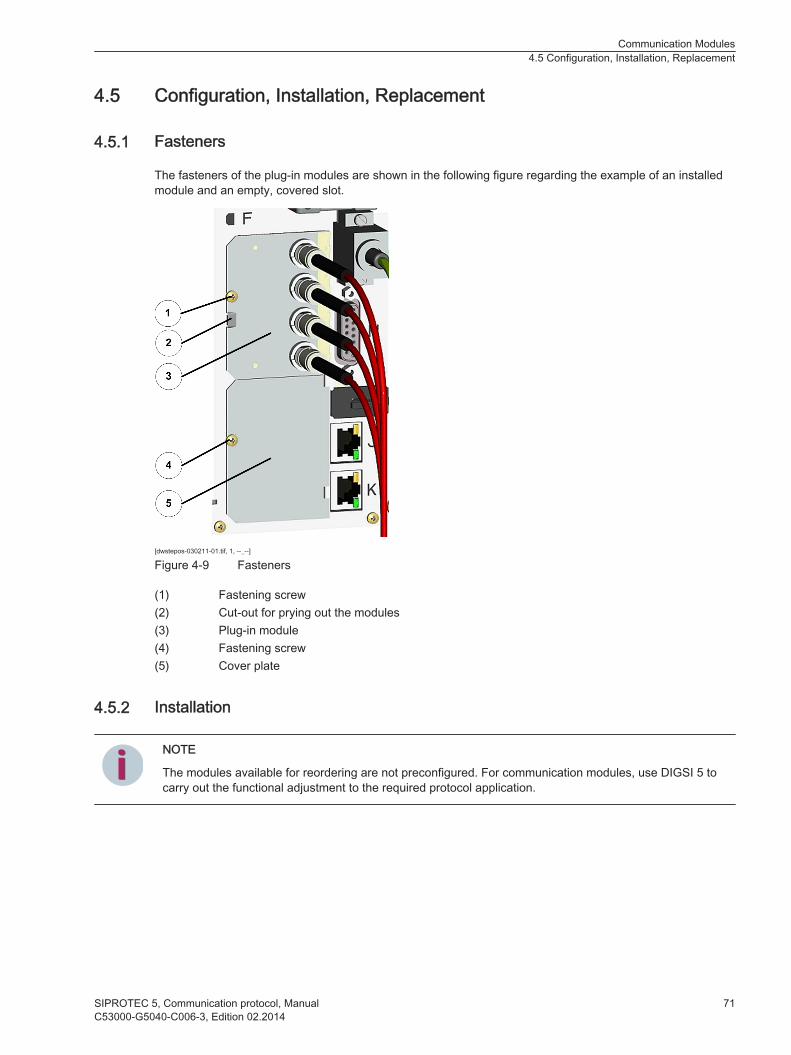
Configuration, Installation, Replacement
Fasteners
The fasteners of the plug-in modules are shown in the following figure regarding the example of an installedmodule and an empty, covered slot.
[dwstepos-030211-01.tif, 1, --_--]
Figure 4-9 Fasteners
(1) Fastening screw(2) Cut-out for prying out the modules(3) Plug-in module(4) Fastening screw(5) Cover plate
Installation
iiNOTE
The modules available for reordering are not preconfigured. For communication modules, use DIGSI 5 tocarry out the functional adjustment to the required protocol application.
4.5
4.5.1
4.5.2
Communication Modules4.5 Configuration, Installation, Replacement
SIPROTEC 5, Communication protocol, Manual 71C53000-G5040-C006-3, Edition 02.2014

Preparing Installation
! DANGERDanger due to live voltage when installing the plug-in modules.
Noncompliance with the safety notes will result in death or severe injuries.
² Install plug-in modules on the electrically deactivated device only.
! CAUTIONExercise caution with laser beams of the optical plug-in modules.
Noncompliance with the safety notes can result in medium-severe or slight injuries.
² Do not look directly into the optical fiber terminals of the active optical plug-in modules, not even withoptical devices. The laser beams can damage the eyes.
² De-energize the device.
iiNOTE
Laser class 1 is adhered to in compliance with EN 60825-1 and EN 60825-2, in the case of ≤ 62.5 μm/125 μm optical fibers.
² In the case of a surface-mounted device with integrated on-site operation panel, remove the entire on-site operation panel.
² Undo the fastening screw and remove the cover plate from the plug-in module position.
Installing the Plug-In Module
² Push in the plug-in module on the inner guide as far as it will go.
² Ensure that the EMC contact spring is seated correctly.
² Bolt down the plug-in module on the assembly frame to a torque of 0.4 Nm.
² Connect the leads to the terminals.
² Then check for secure attachment of the connectors.
² If necessary, fit the on-site operation panel again.
Completing Installation
² Resume operation of the device.
Replacement
iiNOTE
The modules available for reordering are not preconfigured. Use DIGSI 5 to carry out the functional adjust-ment to the required protocol application.
4.5.3
Communication Modules4.5 Configuration, Installation, Replacement
72 SIPROTEC 5, Communication protocol, ManualC53000-G5040-C006-3, Edition 02.2014
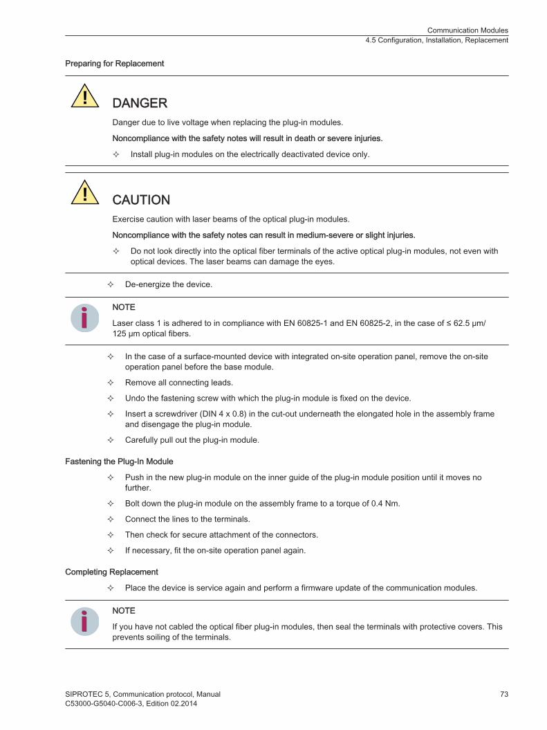
Preparing for Replacement
! DANGERDanger due to live voltage when replacing the plug-in modules.
Noncompliance with the safety notes will result in death or severe injuries.
² Install plug-in modules on the electrically deactivated device only.
! CAUTIONExercise caution with laser beams of the optical plug-in modules.
Noncompliance with the safety notes can result in medium-severe or slight injuries.
² Do not look directly into the optical fiber terminals of the active optical plug-in modules, not even withoptical devices. The laser beams can damage the eyes.
² De-energize the device.
iiNOTE
Laser class 1 is adhered to in compliance with EN 60825-1 and EN 60825-2, in the case of ≤ 62.5 μm/125 μm optical fibers.
² In the case of a surface-mounted device with integrated on-site operation panel, remove the on-siteoperation panel before the base module.
² Remove all connecting leads.
² Undo the fastening screw with which the plug-in module is fixed on the device.
² Insert a screwdriver (DIN 4 x 0.8) in the cut-out underneath the elongated hole in the assembly frameand disengage the plug-in module.
² Carefully pull out the plug-in module.
Fastening the Plug-In Module
² Push in the new plug-in module on the inner guide of the plug-in module position until it moves nofurther.
² Bolt down the plug-in module on the assembly frame to a torque of 0.4 Nm.
² Connect the lines to the terminals.
² Then check for secure attachment of the connectors.
² If necessary, fit the on-site operation panel again.
Completing Replacement
² Place the device is service again and perform a firmware update of the communication modules.
iiNOTE
If you have not cabled the optical fiber plug-in modules, then seal the terminals with protective covers. Thisprevents soiling of the terminals.
Communication Modules4.5 Configuration, Installation, Replacement
SIPROTEC 5, Communication protocol, Manual 73C53000-G5040-C006-3, Edition 02.2014

74 SIPROTEC 5, Communication protocol, ManualC53000-G5040-C006-3, Edition 02.2014

Commissioning and Diagnostics
5.1 Diagnostic Information 76
5.2 Diagnostic Variables 78
5
SIPROTEC 5, Communication protocol, Manual 75C53000-G5040-C006-3, Edition 02.2014
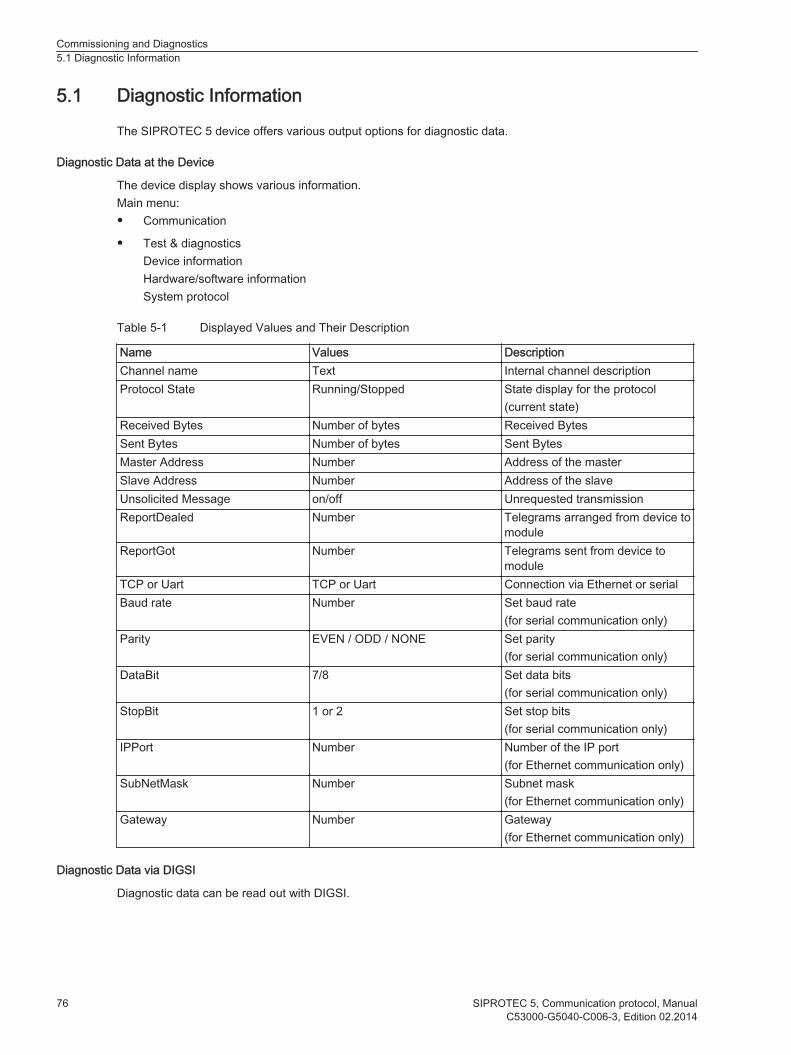
Diagnostic Information
The SIPROTEC 5 device offers various output options for diagnostic data.
Diagnostic Data at the Device
The device display shows various information.Main menu:• Communication
• Test & diagnosticsDevice informationHardware/software informationSystem protocol
Table 5-1 Displayed Values and Their Description
Name Values DescriptionChannel name Text Internal channel descriptionProtocol State Running/Stopped State display for the protocol
(current state)Received Bytes Number of bytes Received BytesSent Bytes Number of bytes Sent BytesMaster Address Number Address of the masterSlave Address Number Address of the slaveUnsolicited Message on/off Unrequested transmissionReportDealed Number Telegrams arranged from device to
moduleReportGot Number Telegrams sent from device to
moduleTCP or Uart TCP or Uart Connection via Ethernet or serialBaud rate Number Set baud rate
(for serial communication only)Parity EVEN / ODD / NONE Set parity
(for serial communication only)DataBit 7/8 Set data bits
(for serial communication only)StopBit 1 or 2 Set stop bits
(for serial communication only)IPPort Number Number of the IP port
(for Ethernet communication only)SubNetMask Number Subnet mask
(for Ethernet communication only)Gateway Number Gateway
(for Ethernet communication only)
Diagnostic Data via DIGSI
Diagnostic data can be read out with DIGSI.
5.1
Commissioning and Diagnostics5.1 Diagnostic Information
76 SIPROTEC 5, Communication protocol, ManualC53000-G5040-C006-3, Edition 02.2014
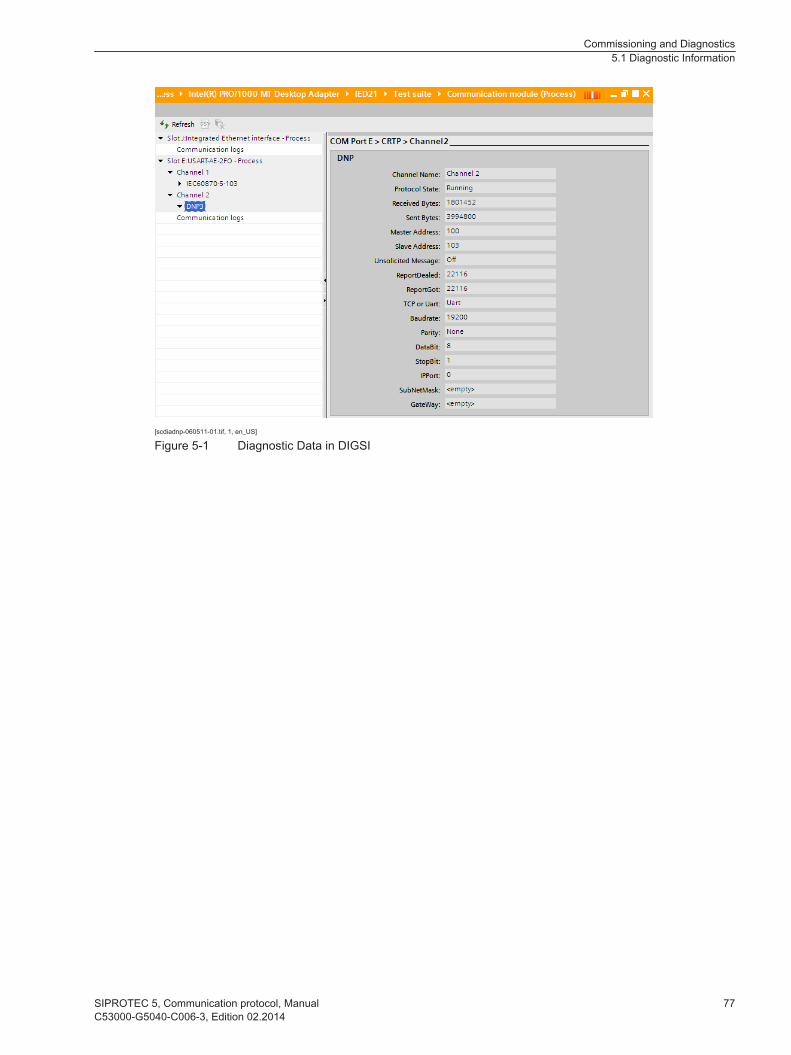
[scdiadnp-060511-01.tif, 1, en_US]
Figure 5-1 Diagnostic Data in DIGSI
Commissioning and Diagnostics5.1 Diagnostic Information
SIPROTEC 5, Communication protocol, Manual 77C53000-G5040-C006-3, Edition 02.2014

Diagnostic Variables
Communication Log
You can open the communication log via the following steps:• In DIGSI, select the area Online Access in Project Tree.
• Then select the interface to which the device is connected.
• Next, select Updating accessible participants. The local network is searched for SIPROTEC 5 devices.
• Next, select the device and click Get all data from device. The configuration and process data are readout.
• Next, select Test Suite and then Communication module. You can now open the communication log foreach communication module under the settings for the channels.
[scdistdg-120213-01.tif, 1, en_US]
Figure 5-2 Communication Log
Variables in the Communication Log
The communication log contains the following variables:
Variable MeaningForce the module into fallback mode! The mainboard has sent a signal to start the fallback
mode only for a certain reason, for example, incon-sistent settings files DCF/CCF
The module has been rebooted for the 3rd timeunsuccessfully!
A fault remains in the 1st or 2nd start level after the3rd restart attempt and is in fallback (without theprotocols having been started)
-- MODULE STOPS WORKING -- Module stopped.Too many initialization errors during 1st level comstartup!
Start of the 1st level has failed.
Wrong module at... The module parameter settings do not match themodule that is inserted.
Protocol8 found in configuration file Start of the 1st level OK.ComObj available (DCF parsing successful)
Launching protocol (handle 0x%x) failed! Start of the protocol has failed. Possible reasons:Delayed connection failed?No so-file?
Protocol successfully launched. Start of the 1st level OKComObj available (DCF parsing successful)Protocols have started
Too many initialization errors during 2nd level comstartup!
Start of the 2nd level has failed
5.2
8For example, protocol IEC 60870-5-103, IEC 60870-5-104, or DNP3
Commissioning and Diagnostics5.2 Diagnostic Variables
78 SIPROTEC 5, Communication protocol, ManualC53000-G5040-C006-3, Edition 02.2014

Variable MeaningSet of module Health failed! No ComLink connection
Problems with SessionMngrWrong readiness path?
Startup finished ComBase-Start finishedProcess mode: Protocols runningFallback mode: Protocols not running
Module PCB type PCB typeModule9 detected in slot 1 (port F). Module is inserted in Port F
Module core runningNFS running!
Module detected in slot 2 (port E). Module is inserted in Port EModule core runningNFS running!
Module detected in slot 3 (port P). Module is inserted in Port PModule core runningNFS running!
Module detected in slot 4 (port N). Module is inserted in Port NModule core runningNFS running!
CCF GUID(%s) check failed at slot%i! DCF and CCF are inconsistent, GUIDs are not iden-tical.
CCF compKey(%s) check failed at slot%i! DCF and CCF are inconsistent, compKeys are notidentical.
9This is where the type of module is indicated, for example, USART-AE-2FO V1.00.
Commissioning and Diagnostics5.2 Diagnostic Variables
SIPROTEC 5, Communication protocol, Manual 79C53000-G5040-C006-3, Edition 02.2014

80 SIPROTEC 5, Communication protocol, ManualC53000-G5040-C006-3, Edition 02.2014

Troubleshooting
6.1 Troubleshooting 82
6
SIPROTEC 5, Communication protocol, Manual 81C53000-G5040-C006-3, Edition 02.2014

Troubleshooting
Information on the Communication Module
iiNOTE
If you wish to rectify faults, Siemens recommends using the information on the communication module.• Refer to the documentation for information about the communication module or the display on the
device (see chapter Commissioning and Diagnostics).
Connection Not Possible
Proceed as follows during the troubleshooting:• Check whether all connection lines are correctly installed:
– In the case of serial connections: Between the device and the Communication Master (only appliesfor communication protocols DNP3 and IEC 60870-5-103)
– In the case of Ethernet connections: Between the device and switch (only applies for the communi-cation protocol DNP3/IEC 60870-5-104)
• Check whether the device address and settings of the data-link layer (data bits, stop bits, and parity) areset in the device (only applies for communication protocols DNP3 and IEC 60870-5-103).
• Check whether the correct protocol firmware is loaded.
Time Synchronization Not Possible
Proceed as follows during the troubleshooting:• Check whether the master sends a valid time telegram.
• Check whether the time synchronization is parameterized via the corresponding communicationprotocol.
Error message Msg[transmit failed, will retry] number: 5292
iiNOTE
The error message Msg[transmit failed, will retry] number: 5292 may occur. This error message is not rele-vant. You can ignore the error message.
6.1
Troubleshooting6.1 Troubleshooting
82 SIPROTEC 5, Communication protocol, ManualC53000-G5040-C006-3, Edition 02.2014

Glossary
ACD
IEC 61850 data type: Directional protection activation information
ACK
Data transfer acknowledgment
ACT
IEC 61850 data type: Protection activation information
BCR
IEC 61850 data type: Binary counter reading
CRC
Cyclic redundancy check
DIGSI
Configuration software for SIPROTEC
DPC
IEC 61850 data type: Double Point Control
DPS
IEC 61850 data type: Double-point status
GOOSE
Generic Object-Oriented Substation Event.
High Availability Seamless Redundancy Protocol
Like PRP (Parallel Redundancy Protocol), HSR (High Availability Seamless Redundancy Protocol) is speci-fied in IEC 62439-3. Both protocols offer redundancy without switching time.The principal function can be found in the definition of PRP. With PRP, the same message is sent via 2 sepa-rated networks. In contrast to this, in the case of HSR the message is sent twice in the 2 directions of the ring.The recipient receives it correspondingly via 2 paths in the ring, takes the 1st message and discards the 2nd(see PRP).Whereas NO messages are relayed in the end device in the case of PRP, a switch function is installed in theHSR node. Thus, the HSR node relays messages in the ring that are not directed at it.In order to avoid circular messages in the ring, corresponding mechanisms are defined in the case of HSR.SAN (Single Attached Node) end devices can only be connected with the aid of a REDBOX in the case ofHSR. PRP systems and HSR systems can be coupled redundantly with 2 REDBOXES.
SIPROTEC 5, Communication protocol, Manual 83C53000-G5040-C006-3, Edition 02.2014

HSR
High Availability Seamless Redundancy Protocol
IEC
International Electrotechnical Commission – International electrotechnical standardization body
IP
Internet protocol
Management Information Base
A Management Information Base (MIB) is a database which continuously saves information and statisticsconcerning each device in a network. The performance of each device can be monitored with this informationand statistics. In this way, it can also be ensured that all devices in the network function properly. MIBs areused with SNMP.
MIB
Management Information Base
NACK
Negative acknowledgment
Parallel Redundancy Protocol
Parallel Redundancy Protocol (PRP) is a redundancy protocol for Ethernet networks that is specified in IEC62439-3. Unlike conventional redundancy procedures, such as RSTP (Rapid Spanning Tree Protocol, IEEE802.1D-2004) PRP offers uninterruptible switching, which avoids any down time in the event of a fault, andthus the highest availability.PRP is based on the following approach: The redundancy procedure is generated in the end device itself.The principle is simple: The redundant end device has 2 Ethernet interfaces with the same address (DAN,Double Attached Node). Now the same message is sent twice, in the case of PRP (parallel) to 2 separatenetworks, and uniquely marks both with a sequence number. The recipient takes the information that itreceives first, stores its ID based on the source address and the sequence number in a duplicate filter andthus recognizes the 2nd, redundant information. This redundant information is then discarded. If the 1stmessage is missing, the 2nd message with the same content comes via the other network. This redundancyavoids a switching procedure in the network and is thus interruption-free. The end device relays no messagesto the other network. Since the process is realized in the Ethernet layer (same MAC address), it is transparentand usable for all Ethernet payload protocols (IEC 61850, DNP, other TCP/IP based protocols). In addition, itis possible to use one of the 2 networks for the transmission of non-redundant messages.There are 2 versions of PRP: PRP-0 and its successor PRP-1. Siemens implements PRP-1.
PRP
Parallel Redundancy Protocol
RSTP
Rapid Spanning Tree Protocol
SBO
Select before operate
SIPROTEC
The registered trademark SIPROTEC designates the product family of protection devices and fault recorders.
Glossary
84 SIPROTEC 5, Communication protocol, ManualC53000-G5040-C006-3, Edition 02.2014

SNMP
Simple Network Management Protocol
SNTP
Simple Network Time Protocol
SPC
IEC 61850 data type: Single Point Control
SPS
IEC 61850 data type: Single point status
SPS
Programmable Logic Controller
TCP
Transmission Control Protocol
Transmission Control Protocol
The Transmission Control Protocol (TCP) is a transmission protocol for transport services in the Internet. TCPis based on IP and ensures connection of the participants during the data transmission. TCP ensures thecorrectness of the data and the correct sequence of the data packets.
UDP
User Datagram Protocol
USART
Universal Synchronous/Asynchronous Receiver/Transmitter
UTC
Universal Time Coordinated
Glossary
SIPROTEC 5, Communication protocol, Manual 85C53000-G5040-C006-3, Edition 02.2014

86 SIPROTEC 5, Communication protocol, ManualC53000-G5040-C006-3, Edition 02.2014
Index
A
Adaptingmapping 44
C
Communication module 58, 62configuration 39Ethernet module 68Module designation 61, 62serial 65Serial 30
Communication ModuleSelect 38
ConnectionNot Possible 82
Copymapping 52
D
DCPDiscovery and Basic Configuration Protocol 16
Discovery and Basic Configuration ProtocolDCP 16
E
EthernetCommunication 21, 33Module 33
Ethernet serviceDCP 16, 16, 16DIGSI 5 protocol 16RSTP 17SNMP 17SNTP 16, 16STMP 17
Exportmapping 53
H
Hardware Catalog 38
M
MappingCustomers 43Select 43Standard 43
O
OSI model 10Application layer 12Data link layer 11Physical layer 10
P
Parameterizingtime synchronization 55
Plug-in module positionon the base module 62on the CB202 expansion module 62
Plug-in modulesFasteners 71Install 71Replace 72
Project Tree 38, 38
R
Rapid Spanning Tree ProtocolRSTP 17
RJ45 socket 64RS485 64RSTP
Rapid Spanning Tree Protocol 17
SIPROTEC 5, Communication protocol, Manual 87C53000-G5040-C006-3, Edition 02.2014

S
Simple Network Management ProtocolSNMP 17
Simple Network Time ProtocolSNTP 17
SNMPSetting 17Simple Network Management Protocol 17
SNTPSimple Network Time Protocol 17Time server 17Time synchronization 17
T
Time SynchronizationNot Possible 82
Index
88 SIPROTEC 5, Communication protocol, ManualC53000-G5040-C006-3, Edition 02.2014