Embed Size (px)
Citation preview

Protection Systems
CatalogSIP 6.1 ⋅ 2000
SIPROTEC 47UM611/612Multifunction Generator Protection Relay


Generator Protection RelayPage
Description 2 to 5
DIGSI 4 Operating program 6 and 7
Communication 8 and 9
Functions 10 to 13
Typical applications 14 to 17
Technical data 18 to 25
Selection and ordering data 26
Connection diagrams 28 and 29
Siemens SIP 6.1 ⋅ 2000 1
Siemens AG 2000
SIPROTEC 47UM611/612MultifunctionGenerator Protection RelayFirmwareversion 4.0
Catalog SIP 6.1 ⋅ 2000
Accessories 27
~ Advantages to youn Cost-effectiveness
n High degree of automation
n User-friendly operation
n Low planning and engineeringeffort
n Fast, flexible mounting, reducedwiring
n Simple, short commissioning
n Simple spare part stocking
n High flexibility
n High reliability and availability
n State-of-the-art technology
n Compliance with internationalstandards
n Integration in a control system
Dimensions 30 and 31
Application
The 7UM6 protection relays ofthe SIPROTEC 4 range arecompact multifunction unitswhich have been developedfor small to medium-sizedpower generation plants. Theyincorporate all the necessaryprotective functions and areespecially suitable for the pro-tection of:− Hydro and pumped-storage
generators− Cogeneration stations− Private power stations using
regenerative energy sourcessuch as wind or biogases
− Power generation withdiesel generators
− Gas turbine power stations− Industrial power stations
and− Conventional steam power
stations.They can also be employed forprotection of motors and trans-formers.The numerous other additionalfunctions assist the user in en-suring cost-effective systemmanagement and reliablepower supply. Measured val-ues display current operatingconditions. Stored status indi-cations and fault recording pro-vide assistance in fault diagno-sis not only in the event of adisturbance in generator oper-ation.Combination of the unitsmakes it possible to imple-ment effective redundancyconcepts.
Uniform design
The SIPROTEC 4 units have auniform design and a degreeof functionality which repre-sents a whole new quality inprotection and control.Local operation has been de-signed according to ergonomiccriteria. Large, easy-to-readdisplays were a major designaim. The DIGSI 4 operatingprogram considerably simpli-fies planning and engineeringand reduces commissioningtimes.
Highly reliable
The 7UM6 hardware is basedon 20 years of Siemens experi-ence with numerical protectionequipment. State-of-the-arttechnology and a high-effi-ciency 32-bit microprocessorare employed. Production issubject to exacting qualitystandards. Special attentionhas been paid to electromag-netic compatibility and thenumber of electronic moduleshas been drastically reducedby the use of highly integratedcircuits.The software design incorpo-rates accumulated experienceand the latest technical knowl-edge. Object orientation andhigh-level languageprogramming, combined withthe continuous quality assur-ance system, ensure maxi-mized software reliability.
Programmable logic
The integrated programmablelogic function allow the user toimplement his own functionsfor automation of switchgear(interlocking) via a graphic userinterface. The user can alsogenerate user defined mes-sages. Adjustments can easilybe made to the varying powerstation requirements.
Protection functions
Numerous protection func-tions are necessary for reliableprotection of electrical ma-chines. Their extent and com-bination are determined by avariety of factors, such as ma-chine size, mode of operation,plant configuration, availabilityrequirements, experience anddesign philosophy.This leads of necessity tomultifunctionality, which is im-plemented in outstandingfashion by numerical technol-ogy.In order to satisfy differing re-quirements, the combinationof functions is scalable (seeTable 1). Selection is facilitatedby division into three groups.
• Basic configuration
One application is concen-trated on small generators oras backup protection for largergenerators. The function mix isalso an effective addition totransformer differential protec-tion with parallel-connectedtransformers. The functionsare also suitable for systemdisconnection.
• Standard configuration
This function mix is recom-mended for generator outputsexceeding 1 MVA.It is also suitable for protectionof synchronous motors.Another application is as back-up protection for the largerblock units.
• Full configuration
Here, all protection functionsare available and are recom-mended from generator out-puts exceeding 5 MVA.Backup protection for thelarger block units is also a rec-ommended application.
SIPROTEC 4 7UM611/612Multifunction Generator Protection RelayDescription
2 Siemens SIP 6.1 ⋅2000
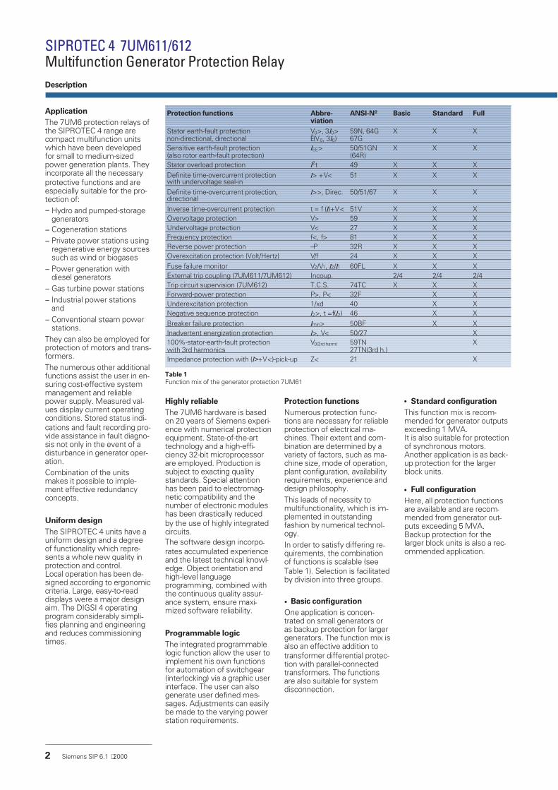
Table 1Function mix of the generator protection 7UM61
Protection functions Abbre-viation
ANSI-Nº Basic Standard Full
Stator earth-fault protectionnon-directional, directional
V0>, 3I0>Ë(V0, 3I0)
59N, 64G67G
X X X
Sensitive earth-fault protection(also rotor earth-fault protection)
IEE> 50/51GN(64R)
X X X
Stator overload protection I2t 49 X X XDefinite time-overcurrent protectionwith undervoltage seal-in
I> +V< 51 X X X
Definite time-overcurrent protection,directional
I>>, Direc. 50/51/67 X X X
Inverse time-overcurrent protection t = f (I)+V< 51V X X XOvervoltage protection V> 59 X X XUndervoltage protection V< 27 X X XFrequency protection f<, f> 81 X X XReverse power protection –P 32R X X XOverexcitation protection (Volt/Hertz) V/f 24 X X XFuse failure monitor V2/V1, I2/I1 60FL X X XExternal trip coupling (7UM611/7UM612) Incoup. 2/4 2/4 2/4Trip circuit supervision (7UM612) T.C.S. 74TC X X XForward-power protection P>, P< 32F X XUnderexcitation protection 1/xd 40 X XNegative sequence protection I2>, t =f(I2) 46 X XBreaker failure protection Imin> 50BF X XInadvertent energization protection I>, V< 50/27 X100%-stator-earth-fault protectionwith 3rd harmonics
V0(3rd harm) 59TN27TN(3rd h.)
X
Impedance protection with (I>+V<)-pick-up Z< 21 X

Measurement
Based on years of experience,high-efficiency protection algo-rithms have been imple-mented which are adapted es-pecially to generator behavior.Thus, irrespective of the gen-erator frequency at the time, ahigh degree of measurementaccuracy is achieved by virtueof the sampling frequency cor-rection in the range of11 to 69 Hz. Filter algorithmssuppress the higher frequencytransient phenomena andaperiodic DC components.
Unit configuration
The units are available in 2 ver-sions – as the 7UM611 in1/3 19-inch and the 7UM612 in½ 19-inch width. The softwarefunctions and subassemblybreakdown are identical. The7UM612 possesses more bi-nary inputs and outputs and issuitable for incorporation inolder or more complex plants.
Communication
The SIPROTEC 4 units pos-sess up to three serialinterfaces:− Front interface for connect-
ing a PC− Service interface for con-
necting a PC via modem− System interface for con-
necting to a control systemvia IEC 60870-5-103 orPROFIBUS-DP;Modbus RTUand an input for
− Time synchronization viaIRIG B or DCF 77
Operational measured val-ues
In order to assist system man-agement and for commission-ing purposes, all relevant mea-sured values are displayed asprimary and secondary valueswith unit and values relating tothe object to be protected.The measured values can alsobe transferred via the serial in-terfaces.In addition, the programmablelogic permits limit value scansand status indications derivedtherefrom.Metered values are available inthe form of energy meteredvalues for the active and reac-tive energy supplied and arealso provided by anelapsed-hour meter.
Operational indications
The SIPROTEC 4 units provideextensive data for fault analy-sis, as well as control. All indi-cations listed below are pro-tected against power supplyfailure.
• Fault indications
The last eight faults arestored in the unit at all times.A fresh fault erases the old-est one. The fault indicationspossess a time resolution of1 ms. They provide detailedinformation on fault history.The buffer memory is de-signed for a total of 600 indi-cations.
• Operational indications
All indications that are not di-rectly associated with thefault (e.g. operating orswitching actions) are storedin the status indicationbuffer. The time resolution is1 ms, buffer size: 200 indica-tions.
Fault recording up to 5 or 80seconds
An instantaneous value orRMS value recorder is pro-vided. The firmware permitsstorage of 8 fault recordings.Triggering can be effected bymeans of pickup, tripping, bi-nary input, the DIGSI 4 operat-ing program or by the controlsystem.In the case of the instanta-neous value recording, the in-put variables (4 x u and 4 x i )are recorded at increments of1.25 ms at 50 Hz or 1.04 ms at60 Hz. The total duration is5 seconds. If the time is ex-ceeded, the oldest fault re-cording in each case is over-written.If protection functions withlong delay times are activated,the RMS Value recording isrecommended. Storage of rel-evant calculated variables (V1,VE, I1, I2, IEE, P, Q, f-fn) takesplace at increments of one cy-cle. The total time is 80 sec-onds.
Time synchronization
A battery-backed clock is astandard component and canbe synchronized via a synchro-nization signal (DCF77; IRIG Bvia satellite receiver), binary in-put, system interface orSCADA (e.g. SICAM). A dateand time are assigned to everyindication.
Freely assignable binary in-puts and outputs
Binary inputs, output relaysand the LEDs are assignablewith indications, user-specifi-cally and independently of oneanother.The tripping matrix is imple-mented by means of the firm-ware. It is simplicity itself toset the tripping programs. Thefirmware assists primary test-ing by functional suppressionof the trip command.
Continuous self-monitoring
The hardware and softwareare continuously monitored. Ifabnormal conditions are de-tected, the unit signal immedi-ately. In this way, a great de-gree of safety, reliability andavailability is achived.
Reliable battery monitoring
The battery buffers the indica-tions and fault recordings inthe event of power supplyvoltage failure. Its function ischecked at regular intervals bythe processor. If the capacityof the battery is found to bedeclining, an alarm indication isgenerated.All setting parameters arestored in the Flash-EPROMwhich are not lost if the powersupply or battery fails. TheSIPROTEC 4 unit remains fullyfunctional.
Siemens SIP 6.1 ⋅2000 3
Figure 1LSP2156f.tif

Operation
User-friendly local operation
Many advantages are alreadyto be found on the clear anduser-friendly front panel: Positioning and grouping of
the keys supports the natu-ral operating process
Large non-reflective back-litdisplay
Programmable (freely as-signable) LEDs for impor-tant messages
Arrows arrangement of thekeys for easy navigation inthe function tree
Operator-friendly input ofthe setting values via thenumeric keys or DIGSI 4
Four programmable keysfor frequently used func-tions >at the press of a but-ton<
SIPROTEC 4 7UM611/612Multifunction Generator Protection RelayDescription
Local operation
All operator actions can be ex-ecuted and information dis-played on an integrated userinterface:
On the LCD display, process and device infor-mation can be displayed as text in variouslists. Frequently displayed information in-cludes protection information, metered val-ues, protection information, general indica-tions and alarms as well as binary informationon inputs and outputs.
Seven (fourteen for 7UM612) configurable(parameterizable) LEDs are used to displayany process or device information. The LEDscan be labeled based on user requirements.An LED reset key resets the LEDs.
Four configurable function keys permit theuser to execute frequently used actions fastand simple. Typical applications include jumpsto certain points in the menu tree to displaythe operational measured values orindications
Keys for navigation
Figure 2
SIPROTEC 4 7UM611
LSP2
175f
.tif
RS232 operator interface
4 Siemens SIP 6.1 ⋅2000

Siemens SIP 6.1 ⋅2000 5
Connection techniques andrack mounting case with nu-merous advantages
The 7UM611 is configured in1/3 19 inch, and the 7UM612 in½ 19 inch width. This meansthat the units of previous mod-els can be replaced.The height throughout all casewidth increments is 243 mm.All wires are connected di-rectly or by means of cablering lugs.Alternatively, versions withplug-in terminals are also avail-able. These permit the use ofprefabricated cable harnesses.In the case of surface panelmounting, the connecting ter-minals are in the form ofscrew terminals at top and bot-tom. The communication inter-faces are also arranged on thesame sides.Dimension drawings areshown on pages 32 and 33.
Figure 4Rear view withscrew terminal
Figure 5Rear view with wiringterminal safety cover andserial interface
LSP2
099f
.eps
LSP2
166f
.eps
7UM612Figure 37UM611
LSP2
176f
.eps
LSP2
177f
.eps

DIGSI 4, the PC program foroperating protection relays
The PC operating programDIGSI 4 is the interface be-tween the user and theSIPROTEC 4 units. It has amodern, intuitive operator in-terface. With DIGSI 4, theSIPROTEC 4 units can be con-figured and queried - it is a tai-lored program for the energysupply and manufacturing in-dustries.The software runs underWindows (Version 95 andhigher, as well as NT).
Simple protection setting
The protection functions re-quired can be selected fromthe wide range provided(Fig. 7). This means that trans-parency in subsequent menusis enhanced.The newly introduced primarydisplay (settings are related tonominal values of the object tobe protected) permits stan-dardization of the setting val-ues. Pressing a button effectsconversion to secondary val-ues and loading into the pro-tection unit.
DIGSI 4 matrix
The DIGSI 4 matrix allows theuser to see the overall view ofthe unit configuration at aglance. For example, you candisplay all the LEDs that havebinary inputs or show any indi-cation that are connected tothe relay. And with one click ofthe button connections can beswitched.By utilizing filter functions, onlyallocated information is ren-dered visible. In addition, it ispossible to alter the viewingmodes. In “Binary Output”viewing mode (output relays),the tripping matrix is clearlydisplayed.
SIPROTEC 4 7UM611/612Multifunction Generator Protection Relay
6 Siemens SIP 6.1 ⋅2000
DIGSI 4 Operating program
Figure 6DIGSI 4, main menue
Figure 8DIGSI 4, allocation matrix
Figure 7DIGSI 4, some protection functions
LSP2
178f
.tif
LSP2
179f
.tif
LSP2
180f
.tif

CFC: Reduced time and plan-ning for programming logic
With the help of the CFC (Con-tinuous Function Chart), youcan configure interlocks andswitching sequences simplyby drawing the logic se-quences; no special knowl-edge of software is required.Logical elements, such asAND, OR and time elements,measured limit values, etc. areavailable.
Commissioning
Special attention has beenpaid to commissioning. All bi-nary inputs and outputs can beread and set directly. This cansimplify the wire checking pro-cess significantly for the user.For primary testing, it is possi-ble to activate a transmissionlockout to prevent any infor-mation being transmitted viathe interface to the controlroom. On the other hand, indi-cations can be transmitted in-tentionally for test purposes.
DIGRA 4: Universal programfor fault recording evalua-tion
Fault recordings stored in theprotection system can be visu-ally displayed and evaluated inclear form. It is readily possibleto calculate harmonics, to viewindividual measuring points, todisplay vector and locus dia-grams etc.The Comtrade format makes itpossible to analyze any desiredfault recordings.
The new DIGSI 4
Easy to learn
Clear layout of routing matrix
Substation, feeder and equipment
data management
Password protection
Linked with the SICAM/SIMATIC
software environment
Windows standards Siemens SIP 6.1 ⋅2000 7
Figure 9 CFC logic with module library
Figure 10 Fault recording
LSP2
181f
.tif
LSP2
182f
.tif

With respect to communica-tion, particular emphasisplaced on high levels of flexibil-ity, data integrity and utilizationof standards common in en-ergy automation. The designof the communication mod-ules permits interchangeabilityon the one hand, and on theother hand provides opennessfor future standards (for exam-ple, Industrial Ethernet).
Local PC interface
The PC interface accessiblefrom the front of the unit per-mits quick access to all param-eters and fault event data. Ofparticular advantage is the useof the DIGSI 4 operating pro-gram during commissioning.
Rear-mounted interfaces
On the rear of the unit are lo-cated two communicationmodules which incorporate op-tional equipment comple-ments and readily permit retro-fitting. They assure the abilityto comply with the require-ments of different communi-cation interfaces (electrical oroptical) and protocols(IEC 60870, PROFIBUS,DIGSI).The interfaces make provisionfor the following applications:
• Service interface
In the RS485 Version, sev-eral protection units can becentrally operated withDIGSI4. On connection of amodem, remote control ispossible. This provides ad-vantages in fault clearance,in particular in unmannedpower stations.
• System interface
This is used to carry outcommunication with a con-trol or protection and controlsystem and supports, de-pendent on the module con-nected, a variety of commu-nication protocols and inter-face designs.
IEC 60870-5-103
IEC 60870-5-103 is an interna-tionally standardized protocolfor the efficient solving ofcommunication problems inthe protected area.IEC 60870-5-103 is supportedby a number of protection unitmanufacturers and is usedworld-wide.The generator protection func-tions are stored in the privatepart (published) of the proto-col.
PROFIBUS-DP
PROFIBUS is an internationallystandardized communicationsystem (EN 50170) for com-munication problem solving.Profibus is supported interna-tionally by several hundredmanufacturers and has to datebeen used in more than1,000,000 applications all overthe world.With the Profibus-DP the pro-tection can be directly con-nected to a SIMATIC S5/S7.The transferred data are faultdata, measured values and in-formation from or to the logic(CFC).
MODBUS RTU
MODBUS is also a widely uti-lized communication standardand is used in numerous auto-mation solutions.
Safe bus architecture
RS485 busWith this data transmissionvia copper conductors elec-tromagnetic fault influ-ences are largely elimi-nated by the use oftwisted-pair conductor.Upon failure of a unit, theremaining system contin-ues to operate without anyfaults. Fiber-optic double ring
circuitThe fiber-optic double ringcircuit is immune to electro-magnetic interference.Upon failure of a sectionbetween two units, thecommunication systemcontinues to operate with-out disturbance.
SIPROTEC 4 7UM611/612Multifunction Generator Protection Relay
Figure 13PROFIBUS: RS485 copper conductors
OLM1)
Figure 12PROFIBUS: Optical double ring circuit
8 Siemens SIP 6.1 ⋅2000
Communication
Figure 11IEC 60870-5-103 star-type RS232 copper conductorconnection or fibre-optic connection
1) Optical Link Module

System solution
SIPROTEC 4 is tailor-made foruse in SIMATIC-based auto-mation systems.Via the PROFIBUS DP, indica-tions (pickup and tripping) andall relevant operational mea-sured values are transmittedfrom the protection device.Via modem and service inter-face, the protection engineerhas access to the protectiondevices at all times. This per-mits remote maintenance anddiagnosis (cyclic testing).Parallel to this, local communi-cation is possible, for exampleduring a major inspection.
Siemens SIP 6.1 ⋅2000 9
Figure 14Communication module, optical
Figure 15Communication module RS232, RS485
Figure 16Communication module, optical, double-ring
LSP2
164f
.eps
LSP2
162f
.eps
LSP2
163f
.eps
Figure 17System solution: Communications

Definite time-overcurrentprotectionI>, I>>(ANSI 50, 51, 67)
This protection function com-prises the short-circuit protec-tion for the generator and alsothe back-up protection for up-stream devices such as trans-formers or power system pro-tection.An undervoltage stage at I>maintains the pickup whenduring the fault the currentfalls below the threshold. Inthe case of a voltage drop onthe generator terminals, thestatic excitation system can nolonger be sufficiently supplied.This is one reason for the de-creasing of the short-circuitcurrent.The I>> stage can be imple-mented as high-set instanta-neous trip stage. With the inte-grated directional function itcan be applied for generatorswithout star point c.t. (see Fig-ure 18).
Inverse time-overcurrentprotection (ANSI 51V)
This function also comprisesshort-circuit and back-up pro-tection and is used for powersystem protection with currentdependent protection devices.IEC and ANSI characteristicscan be selected (Table 2).By evaluating the generatorterminal voltage, the currentfunction can be controlled.The “controlled” version re-leases the sensitive set cur-rent stage.With the “restraint” versionthe pickup value of the currentis lowered linearly with de-creasing voltage.The fuse-failure-monitor pre-vents unwanted operation.
Stator overload protection(ANSI 49)
The task of the overload pro-tection is to protect the statorwindings from high, continu-ous overload currents. All loadvariations are evaluated by themathematical model used. Thethermal effect of the rms cur-rent value forms the basis ofthe calculation. This conformsto IEC 60255-8. In dependencyof the current the cooling timeconstant is automatically ex-tended. If the ambient temper-ature or the temperature of thecoolant are injected via thePROFIBUS-DP, the model au-tomatically adapts to theambient conditions; otherwisea constant ambient tempera-ture is assumed.
Negative sequenceprotection(ANSI 46)
Asymmetrical current loads inthe three phases of a genera-tor cause a temperature rise inthe rotor because of the nega-tive sequence field produced.This protection detects anasymmetrical load in three-phase machines. It functionson the basis of symmetricalcomponents and evaluates thenegative sequence of thephase currents. The thermalprocesses are taken into ac-count in the algorithm andform the inverse characteristic.In addition, the negativesequence is evaluated by anindependent stages (alarm andtrip) which are supplementedby a time-delay element (seeFigure 19).
SIPROTEC 4 7UM611/612Multifunction Generator Protection Relay
10 Siemens SIP 6.1 ⋅ 2000
Functions
Figure 18Protection with current transformer on terminal side
Figure 19Characteristic of negative sequence protection
IEC-characteristic
Normal inverse
t T=
−
⋅014
10 02
.,
II p
p
Very inverse
t T=
−
⋅135
11
.
II p
p
Extremely inverse
t T=
−
⋅80
12
II p
p
ANSI-characteristic
Inverse
t D=
−
+
⋅8 9341
1
0179662 0938
. ..
II p
Moderately inverse
t D=
−
+
⋅0 0103
1
0 02280 02
. ..
II p
Very inverse
t D=
−
+
⋅3 922
1
0 09822
. .I
I p
Extremely inverse
t D=
−
+
⋅5 64
1
0 024342
. .I
I p
Definite inverse
t D=
−
+
⋅0 4797
1
0 213591 5625
. ..
II p
Table 2Inverse-timecharacteristics(IP - Pickup value;TP, D - Time dial)

Underexcitation protection(ANSI 40)
Derived from the generatorterminal voltage and current,the complex admittance is cal-culated and corresponds to thegenerator diagram scaled inper unit. This protection pre-vents damage due to loss ofsynchronism resulting fromunderexcitation. The protec-tion function provides threecharacteristics for monitoringstatic and dynamic stability. Incase of exciter failure, fast re-sponse of the protection canbe ensured via binary input.This input releases a timerwith a short time delay..The straight-line characteristicsallow an optimum adaption ofthe protection of the generatordiagram (see Figure 20). Theper-unit-presentation of the di-agram allows direct read-out ofthe setting values.The positive sequence sys-tems of current and voltageare used to calculate theadmittance. This ensures thatthe protection always operatescorrectly even with asymmet-rical network conditions.In the case of a voltage devia-tion from the rated voltage, theadmittance calculation has theadvantage that the characteris-tics move in the same direc-tion as the generator diagram.
Reverse power protection(ANSI 32R)
The reverse power protectionmonitors the direction of ac-tive power flow and respondswhen the mechanical energyfails because then the driveenergy is taken from the net-work. This function providedby the 7UM6 can be used foroperational shutdown of thegenerator but also preventsdamage to the steam turbines.The reverse power is calcu-lated from the positive-sequence systems of currentand voltage. Asymmetricalnetwork faults therefore donot cause reduced measuringaccuracy. The position of theemergency trip valve is in-jected as binary informationand is used to switch betweentwo switch-off command de-lays. When applied for motorprotection, the sign of the ac-tive power can be reversed viaparameters.
Forward power protection(ANSI 32F)
Monitoring of the active powerproduced by a generator canbe useful for starting up andshutting down generators.One stage monitors thresholdbeyond one limit value whileanother stage monitorsthreshold below another limitvalue. The power is calculatedusing the positive-sequencecomponent of current and volt-age.
Impedance protection(ANSI 21)
This fast short-circuit protec-tion protects the generator,the generator transformer andis a backup protection for thepower system. This protectionhas two settable impedancestages; in addition, the firststage can be switched over viabinary input. With the circuit-breaker in “open” position(see Figure 21) the impedancemeasuring range can be ex-tended. The overcurrentpickup element with under-voltage seal-in ensures a reli-able pickup and the loop selec-tion logic a reliable detection ofthe faulty loop. It makes alsopossible a correct measuringvia the generator transformer.
Undervoltage protection(ANSI 27)
The undervoltage protectionevaluates the positive-se-quence components of thevoltages and compares themwith the threshold values.There are two stages availableThe undervoltage function isused for asynchronous motorsand pumped-storage stationsand prevents the volt-age-related instability of suchmachines.The function can also be usedfor monitoring purposes.
Siemens SIP 6.1 ⋅2000 11
Figure 20Characteristic of underexitation protection
Figure 21Grading of impedance protection

Overvoltage protection(ANSI 59)
This protection prevents insu-lation faults that result whenthe voltage is too high.Either the maximumline-to-line voltages or thephase-to-earth voltages (forlow-voltage generators) can beevaluated. The measuring re-sults of the line-to-line voltagesare independent of the neutralpoint displacement caused byearth-faults. This function isimplemented in two stages.
Frequency protection
(ANSI 81)
The frequency protection pre-vents an unpermissible stressof the equipment (e.g. turbine)in case of under- or over-frequency. It also serves as anmonitoring and control ele-ment.The function has four stages ;the stages can be imple-mented either as under-frequency or over-frequencyprotection. Each stage can bedelayed separately.Even in the case of voltagedistortion, the frequency mea-suring algorithm reliably identi-fies the fundamental wavesand determines the frequencyextremely precisely.Frequency measurement canbe blocked by using an un-dervoltage stage.
Overexcitation protectionVolt/Herz(ANSI 24)
The overexcitation protectionserves for detection of anunpermissible high induction(proportional to V/f) in genera-tors or transformers, whichleads to a thermal overloading.This may occur when startingup, shutting down under fullload, with weak systems orunder isolated operation. Theinverse characteristic can beset via seven points derivedfrom the manufacturerdata/curve.In addition, an independentalarm stage and aninstantaneous stage can beused.For calculation of the V /f ratio,frequency and also the highestof the three line-to-line volt-ages are used. The frequencyrange that can be monitoredcomprises 11 to 69 Hz.
Stator earth-fault protection,non-directional, directional(ANSI 59N, 64G, 67G)
Earth faults manifest them-selves in generators that areoperated in isolation by theocurance of a displacementvoltage. In case of unit connec-tions, the displacement volt-age is an adequate, selectivecriterion for protection.For the selective earth-faultdetection, the direction of theflowing earth-current has to beevaluated too, if there is adirect connection betweengenerator and busbar.The protection relay measuresthe displacement voltage at av.t. located at the transformerstar point or at the brokendelta-winding of a v.t. As anoption it is also possible to cal-culate the zero-sequence volt-age from the phase-to-earthvoltages. Depending on theload resistor selection 90 to95 % of the stator winding of agenerator can be protected.A sensitive current input isavailable for the earth currentmeasurement. This inputshould be connected to acore-balance current trans-former. The fault direction isdeduced from the displace-ment voltage and earth cur-rent. The directional character-istic (straight line) can be easilyadapted to the system condi-tions. Effective protection fordirect connection of a genera-tor to a busbar can thereforebe created. During startup, it ispossible to switch over fromthe directional to thedisplacement voltage mea-surement via an externally in-jected signal.Depending on the protectionsetting, various earth fault pro-tection concepts can be imple-mented with this function (seeFigs. 23 to 27).
Sensitive earth-faultprotection(ANSI 50/51GN, 64R)
The sensitive earth current in-put can also be used as sepa-rate earth-fault protection. It isof two-stage form. Secondaryearth currents of 2 mA orhigher can be reliably handled.Alternatively, this input is alsosuitable as rotor earth faultprotection. A voltage withrated frequency (50 or 60 Hz)is connected in the rotor circuitvia the interface unit 7XR61. Ifa higher earth current is flow-ing, a rotor earth fault has oc-curred. Measuring circuit mon-itoring is provided for this ap-plication (see Figure 26).
100%-stator earth-fault pro-tection with 3
rdharmonic
(ANSI 59TN, 27TN (3rd
H.))
Owing to the design, the gen-erator produces a 3rd har-monic that forms a zero sys-tem. It is verifiable by the pro-tection on a broken delta wind-ing or on the neutral trans-former. The magnitude of thevoltage amplitude depends onthe generator and its opera-tion.In the event of an earth fault inthe vicinity of the neutral pointthere is a voltage displace-ment in the 3rd harmonic(dropping in the neutral pointand rising at the terminals).
Depending on the connectionthe protection must be set ineither undervoltage orovervoltage form. It can alsobe delayed. So as to avoidoverfunction, the active powerand the positive sequencevoltage act as enabling criteriaThe final protection setting canbe made only by way of a pri-mary test with the generator.
Breaker failure protection(ANSI 50BF)
In the event of scheduleddowntimes or a fault in thegenerator, the generator canremain on line if the circuit-breaker is defective and couldsuffer substantial damage.Breaker failure protection eval-uates a minimum current andthe circuit-breaker auxiliarycontact. It can be started by in-ternal protective tripping or ex-ternally via binary input.Two-channel activation avoidsoverfunction (see Figure 22).
SIPROTEC 4 7UM611/612Multifunction Generator Protection Relay
12 Siemens SIP 6.1 ⋅ 2000
Functions
Figure 22Logic diagram of breaker failure protection

Inadvertent energizationprotection(ANSI 50, 27)
This protection has the func-tion of limiting the damage ofthe generator in the case of anunintentional switch-on of thecircuit-breaker whether thegenerator is standing still or ro-tating without being excited orsynchronized. If the networkvoltage is connected the gen-erator starts as an asynchron-ous machine with a large slipand this leads to excessivelyhigh currents in the rotor.A logic circuit consisting ofsensitive current measure-ment for each phase, mea-sured variable detector, timecontrol and blocking as of aminimum voltage, leads to aninstantaneous trip command.If the fuse failure monitor re-sponds, this function is inef-fective.
External trip coupling
For recording and processingof external trip informationthere are 2 (for 7UM611) or4 (for 7UM612) binary inputs.They are provided for informa-tion from the Buchholz relay orgenerator-specific commandsand act like a protective func-tion. Each inputs opens a faultevent and can be individuallydelayed by means of a timer.
Trip circuit supervision(ANSI 74TC)
One or two binary inputs canbe used for monitoring the cir-cuit-breaker trip coil includingits incoming cables. An alarmsignal occurs whenever the cir-cuit is interrupted.
Phase rotation reversal
In pumped-storage power sta-tions it is possible for a binaryinput to perform matching tothe current phase rotation(generator / motor operationvia phase rotation reversal).
2 predefinable parametergroups
In the protection the settingvalues can be stored in twodatasets. In addition to thestandard parameter group, thesecond group is provided forcertain operating conditions(pumped-storage power sta-tions). It can be activated viabinary input, local control orDIGSI 4.
Lockout(ANSI 86)
All binary outputs (alarm or triprelays) can be stored like LEDsand reset using the LED resetkey. The lockout state is alsostored in the event of supplyvoltage failure. Reclosure canonly occur after the lockoutstate is reset.
Fuse failure and other moni-toring
The relay comprises high-per-formance monitoring for thehardware and software.The measuring circuits, ana-log-digital conversion, powersupply voltages, memoriesand software sequence(watchdog) are all monitored.The fuse failure function de-tects failure of the measuringvoltage due to short-circuit oropen circuit of the wiring or v.t.and avoids overfunction of theundervoltage elements in theprotection functions.The positive and nega-tive-sequence system (voltageand current) are evaluated.
Filter time
All binary indications can besubjected to a filter time (indi-cation suppression).
Siemens SIP 6.1 ⋅ 2000 13

Direct generator-busconnection
Fig. 23 illustrates the recom-mended standard connectionif several generators supplyone busbar. Phase-to-earthfaults are disconnected by em-ploying the directionalearth-fault criterion. Theearth-fault current is driventhrough the cables of the sys-tem. If this is not sufficient, anearthing transformer con-nected to the busbar suppliesthe necessary current (maxi-mum approximately 10 A) andpermits a protection range ofup to 90 %. The earth-faultcurrent should be detected bymeans of core-balance currenttransformers in order toachieve the necessary sensi-tivity. The displacement volt-age can be used as earth-faultcriterion during starting opera-tions until synchronization isachieved.
Direct generator-bus con-nection with low-resistanceearthing
If the generator neutral pointhas low-resistance earthing,the connection illustrated inFig. 24 is recommended. Inthe case of several generators,the resistance must be con-nected to only one generator,in order to prevent circulatingcurrents (3rd harmonic).For selective earth-fault detec-tion, the earth-current inputshould be looped into the com-mon return conductor of thetwo current transformer sets(differential connection). Thecurrent transformers must beearthed at only one point. Thedisplacement voltage VE is uti-lized as additional enable crite-rion.Balanced DE current trans-formers are desirable with thisform of connection. In thecase of higher generatorpower (for example, IN approxi-mately 2000 A), current trans-formers with a secondarynominal current of 5 A are rec-ommended.
SIPROTEC 4 7UM611/612Multifunction Generator Protection Relay
14 Siemens SIP 6.1 ⋅ 2000
Connections/Typical applications
Figure 24
Figure 23
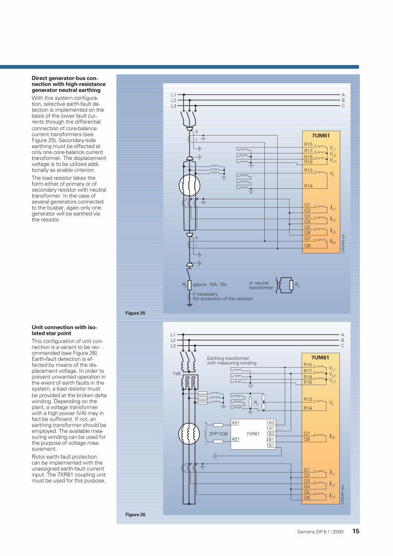
Direct generator-bus con-nection with high-resistancegenerator neutral earthing
With this system configura-tion, selective earth-fault de-tection is implemented on thebasis of the lower fault cur-rents through the differentialconnection of core-balancecurrent transformers (seeFigure 25). Secondary-sideearthing must be effected atonly one core-balance currenttransformer. The displacementvoltage is to be utilized addi-tionally as enable criterion.The load resistor takes theform either of primary or ofsecondary resistor with neutraltransformer. In the case ofseveral generators connectedto the busbar, again only onegenerator will be earthed viathe resistor.
Unit connection with iso-lated star point
This configuration of unit con-nection is a variant to be rec-ommended (see Figure 26).Earth-fault detection is ef-fected by means of the dis-placement voltage. In order toprevent unwanted operation inthe event of earth faults in thesystem, a load resistor mustbe provided at the broken deltawinding. Depending on theplant, a voltage transformerwith a high power (VA) may infact be sufficient. If not, anearthing transformer should beemployed. The available mea-suring winding can be used forthe purpose of voltage mea-surement.Rotor earth-fault protectioncan be implemented with theunassigned earth-fault currentinput. The 7XR61 coupling unitmust be used for this purpose.
Siemens SIP 6.1 ⋅ 2000 15
Figure 26
Figure 25

Unit connection with neutraltransformer
With this system configura-tion, disturbance voltage re-duction and damping in theevent of earth faults in thegenerator area are effected bya load resistor connected togenerator neutral point. Themaximum earth-fault current islimited to approximately 10 A.Configuration can take theform of a primary or secondaryresistor with neutral trans-former. In order to avoid lowsecondary resistance, thetransformation ratio of theneutral transformer should below. The higher secondaryvoltage can be reduced bymeans of a voltage divider.Electrically, the circuit is identi-cal to the above configuration(Figure 26).
Connection withlow-voltage generators
As is generally known, thelow-voltage system is solidlyearthed, so that the generatorneutral point is connected toearth (see Figure 28). With thisconfiguration, there is the riskthat, as a result of the 3rd har-monics forming a zerophase-sequence system, cir-culating currents will flow viathe N-conductor. This must belimited by the generator or sys-tem configuration (reactor).Otherwise, connection corre-sponds to the customary stan-dard. In the case of residualcurrent transformer design, itis to be ensured that the ther-mal current limit (1s) of the IEE
input is restricted to 300 A.
SIPROTEC 4 7UM611/612Multifunction Generator Protection Relay
16 Siemens SIP 6.1 ⋅ 2000
Connections/Typical application
Figure 28
Figure 27

Voltage transformer inopen delta connection(V-connection)
Protection can also be readilyimplemented on voltage trans-formers in open delta-connec-tion. Fig. 29 shows the con-nection involved. If necessary,the operational measured val-ues for the phase-to-earth volt-ages can be slightly asymmet-rical. If this is undesirable, theneutral point (R16) can be con-nected to earth via a capacitor.In the case of open delta-con-nection, it is not possible tocalculate the displacementvoltage from the secondaryvoltages. It must be passed tothe protection device along adifferent path (for example,voltage transformer at the gen-erator neutral point or from theearthing transformer).
Connection with two cur-rent transformers
This configuration is to befound in older systems with in-sulated or high-resistance starpoint. This connection is illus-trated in Fig. 30 opposite. Inthe protection unit, the sec-ondary currents are repre-sented correctly and, in addi-tion, the positive and the nega-tive phase-sequence systemare correctly calculated. Limitsof application occur in the caseof low-resistance and solidearthing.
Siemens SIP 6.1 ⋅2000 17
Figure 30
Figure 29

SIPROTEC 4 7UM611/612Multifunction Generator Protection Relay
Hardware
Analog input Rated frequencyRated current IN
Earth current, sensitive IEmax
Rated voltage VN
Power consumptionwith IN = 1 Awith IN = 5 Afor sensitive earth currentvoltage inputs (with 100 V)
Capability in CT circuitsthermal (rms values)
dynamic (peak)Earth current, sensitive
dynamic (peak)Capability in voltage paths
50 or 60 Hz1 or 5 A1.6 A100 to 125 V
approx. 0.05 VAapprox. 0.3 VAapprox. 0.05 VAapprox. 0.3 VA
100 IN for 1 s30 IN for 10 s4 IN continuous
250 IN (one half cycle)300 A for 1 s100 A for 10 s15 A continuous750 A (one half cycle)230 V continuous
Power supply Rated auxiliary voltage
Permitted toleranceSuperimposed (peak to peak)Power consumption
during normal operation 7UM6117UM612
during pickup with all inputs and outputs activated7UM6117UM612
Bridging time during auxiliary voltage failureat Vaux = 48 V and Vaux ≥ 110 Vat Vaux = 24 V and Vaux = 60 V
24 to 48 V DC60 to 125 V DC110 to 250 V DCand 115 V AC with 50/60 Hz–20 to +20 %≤ 15 %
approx. 4 Wapprox. 4.5 W
approx. 9.5 Wapprox. 12.5 W
≥ 50 ms≥ 20 ms
Binary inputs Number7UM6117UM6122 pickup thresholds
Range is selectable with jumpersMaximum permissible voltageCurrent consumption, energized
71514 to 19 V DC or 66 to 88 V DC
300 V DCapprox. 1.8 mA
Output relays Number7UM6117UM612
Switching capacitymakebreakbreak (for resistive load)break (for L/R ≤ 50 ms)
Switching voltagePermissible current
11 (1 NO))16 (1 NO); 1 (1 NC)
1000 W / VA30 VA40 W25 VA250 V5 A continuous30 A for 0.5 seconds
LED NumberRUN (green)ERROR (red)
Assignable LED (red)7UM6117UM612
11
714
Mechanical construction 7XP20 housingDegree of protection acc. to EN 60529
For surface-mounting housingFor flush-mounting housing
frontrear
For the terminalsWeight
Flush mounting housing7UM611 (1/3 x 19’‘ )7UM612 (1/2 x 19’‘l)
Surface mounting housing7UM611 (1/3 x 19’‘)7UM612 (1/2 x 19’‘)
For dimensions see dimension drawings
IP 51
IP 51IP 50IP 2x with terminal cover put on
approx. 5.5 kgapprox. 7 kg
approx. 7.5 kgapprox. 12 kg
18 Siemens SIP 6.1 ⋅ 2000
Technical data

Serial interfaces
Operating interfacefor DIGSI 4
Connection
Baud rate
Non-isolated, RS232,front panel; 9-pin subminiature connector4800 to 115200 Baud
Time synchronizationIRIG B / DCF 77 signal
Connection
Voltage levels
9-pin subminiature connector, terminal withsurface-mounting caseselectable 5 V or 12 V or 24 V
Service/modeminterface for DIGSI 4 /Modem / Service
Isolated RS232/RS485Test voltageDistance for RS232Distance for RS485
Fiber-optic cableOptical wavelengthPermissible path attenuationBridgeable distance
9-pin subminiature connector500 V / 50 HzMax. 15 mMax. 1000 mIntegrated ST-connectorλ = 820 nmMax. 8 dB for glass-fiber 62.5/125 µmMax. 1.5 km
System interfaceIEC 60870-5-103PROFIBUS DPMODBUS RTU
Isolated RS232/RS485Baud rateTest voltagePermissible distance for RS232Permissible distance for RS485
PROFIBUS RS485Test voltageBaud ratePermissible distance
PROFIBUS fiber-optic cable
Baud rateOptical wavelengthPermissible path attenuationBridgeable distance
9-pin subminiature connector4800 to 115200 Baud500 V / 50 HzMax. 15 mMax. 1000 m
500 V / 50 HzMax. 12 MBaud1000 m bei 93,75 kBaud; 100 m bei 12 MBaudIntegrated ST-connector;Single or double ringmax. 1.5 MBaudλ = 820 nmMax. 8 dB for glass-fiber 62.5/125 µmmax. 1.5 km
Electrical tests
Specifications Standards IEC 60255 (product standards)ANSI/IEEE C37.90.0/.1/.2UL 508DIN 57435 part 303For further standards see “Individual functions”
Insulating tests StandardsVoltage test (100 % test)All circuits except for auxiliary supply, binary inputscommunication and time synchronization interfacesVoltage test (100 % test)Auxiliary voltage and binary inputsVoltage test (100 % test)RS485/RS232 rear side communication interfacesand time synchronization interfaceSurge voltage test (type test)All circuits except for communication interfacesand time synchronization interface, class III
IEC 60255-52.5 kV (rms.), 50/60 Hz
3.5 kV DC
500 V (rms value), 50/60 Hz
5 kV (peak); 1.2/50 µs; 0.5 J;3 positive and 3 negative surgesat intervals of 5 s
EMC tests for noise immunity(type test)
Standards
High frequency testIEC 60255-22-1, class IIIand DIN 57435 part 303, class IIIDischarge of static electricityIEC 60255-22-2 class IVEN 61000-4-2, class IVExposure to RF field, non-modulatedIEC 60255-22-3 (report), class IIIExposure to RF field, amplitude-modulatedIEC 61000-4-3, class IIIExposure to RF field, pulse-modulatedIEC 61000-4-3/ ENV 50204, class IIIFast transient interference burstsIEC 60255-22-4, IEC 61000-4-4, class IV
IEC 60255-6, IEC 60255-22 (product standards)EN 50082-2 (generic standard)DIN 57 435 part 3032.5 kV (peak value), 1 MHz; τ = 15 ms400 pulses per s; duration 2 s
8 kV contact discharge; 15 kV air discharge;both polarities; 150 pF; Ri = 330 Ω
10 V/m; 27 to 500 MHz
10 V/m; 80 to 1000 MHz; 80 % AM; 1 kHz
10 V/m; 900 MHz; repetition frequency 200 Hz;duty cycle 50 %4 kV; 5/50 ns; 5 kHz; burst length = 15 ms;repetition frequency 300 ms; both polarities;Ri = 50 Ω; test duration 1 min
Siemens SIP 6.1 ⋅ 2000 19

SIPROTEC 4 7UM611/612Multifunction Generator Protection Relay
EMC tests for noise immunity(type tests)
High-energy surge voltages (SURGE),IEC 61000-4-5 installation class IIIAuxiliary supply
Measurement inputs, binary inputsand relay outputsConducted RF, amplitude-modulatedIEC 61000-4-6, class IIIMagnetic field with power frequencyIEC 61000-4-8, class IV;IEC 60255-6Oscillatory surge withstand capabilityANSI/IEEE C37.90.1
Fast transient surge withstand capabilityANSI/IEEE C37.90.1Radiated electromagnetic interferenceANSI/IEEE C37.90.2Damped oscillationsIEC 60894, IEC 61000-4-12
Impulse: 1.2/50µs
common (longitudinal) mode: 2 kV; 12 Ω, 9 µFdifferential (transversal) mode:1 kV; 2 Ω, 18 µF
common (longitudinal) mode: 2 kV; 42 Ω, 0.5 µFdifferential (transversal) mode: 1 kV; 42Ω, 0.5 µF10 V; 150 kHz bis 80 MHz; 80 % AM; 1 kHz
30 A/m continuous;300 A/m for 3 s; 50 Hz0.5 mT; 50 Hz2.5 to 3 kV (peak); 1 to 1.5 MHzdamped wave; 50 surges per second;Duration 2 s; Ri = 150 to 200 Ω4 to 5 kV; 10/150 ns; 50 impulses per second;both polarities; Duration 2 s ; Ri = 80 Ω35 V/m; 25 to 1000 MHz
2.5 kV (peak value), polarity alternating 100 kHz,1 MHz, 10 and 50 MHz, Ri = 200 Ω
EMC tests for interferenceemission(type tests)
StandardRadio interference voltage on linesonly auxiliary supply IEC-CISPR 22Interference field strengthIEC-CISPR 22
EN 50081-1 (Basic specification)150 kHz to 30 MHzclass B30 to 1000 MHzclass B
Mechanical dynamic tests
Vibration and shock stressat stationary conditions
StandardsVibrationIEC 60255-21-1, class 2IEC 60068-2-6
ShockIEC 60255-21-2, class 1IEC 60068-2-27Vibration during earthquakeIEC 60255-21-2, class 1IEC 60068-3-3
IEC 60255-21 and IEC 60068Sinusoidal10 to 60 Hz: ±0.075 mm amplitude;60 to 150 Hz: 1 g accelerationFrequency sweep 1 octave/min20 cycles in 3 orthogonal axesHalf-sinusoidalAcceleration 5 g, duration 11 ms,3 shocks each in both directions of the 3 axesSinusoidal1 to 8 Hz: ± 3.5 mm amplitude (horizontal axis)1 to 8 Hz: ± 1.5 mm amplitude (vertical axis)8 to 35 Hz: 1 g acceleration (horizontal axis)8 to 35 Hz: 0,5 g acceleration (vertical axis)Frequency sweep 1 octave/min1 cycle in 3 orthogonal axes
during transport StandardsVibrationIEC 60255-21-1, class 2IEC 60068-2-6
ShockIEC 60255-21-2, class 1IEC 60068-2-27Continuous shockIEC 60255-21-2, class 1IEC 60068-2-29
IEC 60255-21 and IEC 60068-2Sinusoidal5 to 8 Hz: ±7,5 mm amplitude;8 to 150 Hz: 2 g accelerationFrequency sweep 1 octave/min20 cycles in 3 orthogonal axesHalf-sinusoidalAcceleration 15 g, duration 11 ms, 3 shockseach in both directions 3 axesHalf-sinusoidalAcceleration 10 g, duration 16 ms,1000 shocks in both directions of the 3 axes
20 Siemens SIP 6.1 ⋅ 2000
Technical data

Climatic stressTemperatures Standards
Recommended temperature during operationTemporary permissible temperature limit duringoperation
Limit temperature during storageLimit temperature during transportStorage and transport with standardfactory packaging
IEC 60255-6–5 to +55 °C 25 to 131 °F–20 to +70 °C -4 to 158 °F(The legibility of the display may be affectedabove 55 °C/131 °F)–25 to +55 °C -13 to 131 °F–25 to +70 °C -13 to 158 °F
Humidity Permissible humidity stressWe recommend arranging the units in such a waythat they are not exposed to direct sunlight or pronouncedtemperature changes that could cause condensation
Annual average ≤ 75 % relative humidity; on 56days a year up to 93 % relative humidity; condensa-tion during operation is not permitted
Functions
Common Frequency range 11 to 69 Hz
Definite time-overcurrentprotection, directionalANSI 50, 51, 67
Setting rangesOvercurrent I>, I>>
Time delay TUndervoltage seal-in V<Seal-in time of V<Angle of the directional element (at I>)
TimesPickup time I>, I>>at 2 times of set valueat 10 times of set valueDrop-off time I>, I>>
Drop-off ratioDrop-off ratio V<Tolerances
Current pickup (starting) I>, I>>Undervoltage seal-in V<Angle of the directional elementTime delays
0.1 to 8 A (steps 0.01 A); 5 times at IN= 5 A0 to 60 s (steps 0.01 s) or indefinite10 to 125 V (steps 0.1 V)0.1 to 60 s (steps 0.01 s)– 90 ° to + 90 ° (steps 1°)
approx. 35 msapprox. 25 msapprox. 50 msI>: 0.95; I>>: 0.9 to 0,99 (steps 0.01)approx. 1.05
1 % of set value or 10/50 mA1 % of set value or 0.5 V1 °1 % or 10 ms
Inverse time-overcurrentprotectionANSI 51V
Setting rangesPickup overcurrent IPTime multiplier IEC-characteristics TTime multiplier ANSI- characteristics DUndervoltage release V<
Trip characteristicsIECANSI
Pickup thresholdDrop-off threshold
TolerancesPickup threshold IPPickup threshold V<Time for 2 ≤ I/IP ≤ 20
0.1 to 4 A (steps 0.01 A); 5 times at IN = 5A0.05 to 3.2 s (steps 0,01 s) or indefinite0.5 to 15 (steps 0.01) or indefinite10 to 125 V (steps 0.1 V)
Normal inverse; very inverse; extremely inverseInverse; moderately inverse; very inverse;extremely inverse; definite inverseapprox. 1.1 IPapprox. 1.05 IP for IP/IN ≥ 0.3
1 % of set value 10/50 mA1 % of set value or 0.5 V5 % of nominal value + 1 % current toleranceor 40 ms
Stator overloadprotection, thermalANSI 49
Setting rangesFactor k according to IEC 60255-8Time constantTime delay factor at stand stillAlarm overtemperature ΘAlarm/ΘTrip
Overcurrent alarm stage IAlarmTemperature at IN
Scaling temperature of cooling medium
Reset time at emergency startDrop-off ratio
Θ/ΘTripΘ/ΘAlarrmI/IAlarm
Tolerancesregarding k x IP
regarding trip time
0.5 to 2.5 (steps 0.01)30 to 32000 s (steps 1 s)1 to 10 (steps 0.01)70 to 100 % related to the trip temperature(steps 1 %)0.1 to 4 A (steps 0.01 A); 5 times at IN = 5 A40 to 200 °C (steps 1 °C)or 104 to 392 °F (steps 1 °F)40 to 300 °C (steps 1 °C)or 104 to 572 °F (steps 1 °F)20 to 150000 s (steps 1 s)
Drop-off with ΘAlarrnapprox. 0.99approx. 0.95
2 % or 10/50 mA; class 2 % according toIEC 60255-83 % or 1 s: class 3 %according to IEC 60255-8 for I/(k IN)>1.25
Siemens SIP 6.1 ⋅ 2000 21

SIPROTEC 4 7UM611/612Multifunction Generator Protection Relay
Negative sequence protectionANSI 46
Setting rangesPermissible negative sequence I2perm. /INDefinite time trip stage I2>>/INTime delays TAlarm; TI2>>Negative sequence factor KCooling down time TCooling
TimesPickup time (definite stage)Drop-off time (definite stage)
Drop-off ratios I2 perm.; I2 >>Drop-off ratio thermal stageTolerances
Pickup values I2 perm.; I2 >>Time delaysThermal characteristicTime for 2 ≤ I2/I2 perm. ≤ 20
3 to 30 % (steps 1 %)10 to 100 % (steps 1 %)0 to 60 s (steps 0.01 s) or indefinite2 to 40 s (steps 0.1 s)0 to 50000 s (steps 1 s)
approx. 50 msapprox. 50 msapprox. 0.95Drop-off at fall below of I2 perm.
3 % of set value or 0.3 % negative sequence1 % or 10 ms5 % of nominal value +1 % current toleranceor 600 ms
Underexcitation protectionANSI 40
Setting rangesConductance thresholds 1/xd characteristic(3 characteristics)Inclination angle α1, α2, α3Time delay T
TimesStator criterion 1/xd characteristic; αUndervoltage blocking
Drop-off ratioStator criterion 1/xd characteristic; αUndervoltage blocking
TolerancesStator criterion 1/xd characteristicStator criterion αUndervoltage blockingTime delays T
0.25 to 3.0 (steps 0.01)
50 to 120 ° (steps 1 °)0 to 50 s (steps 0.01 s) or indefinite
approx. 60 msapprox. 50 ms
approx. 0.95approx. 1.1
3 % of set value1 ° electrical1 % or 0.5 V1 % or 10 ms
Reverse-power protectionANSI 32
Setting rangesReverse power PRev.>/SNTime delays T
TimesPickup timeDrop-off time
Drop-off ratio PRev.>Tolerances
Reverse power PRev.>Time delays T
–0.5 to –30 % (steps 0.01 %)0 to 60 s (steps 0.01 s) or indefinite
approx. 360 ms (50 Hz); approx. 300 ms (60 Hz)approx. 360 ms (50 Hz); approx. 300 ms (60 Hz)approx. 0.6
0.25 % SN ± 3 % set value1 % or 10 ms
Forward-power protectionANSI 32F
Setting rangesForward power PForw.</SNForward power PForw.>/SNTime delays T
TimesPick-up time (accurate measuring)Pick-up time (fast measuring)Drop-off time (accurate measuring)Drop-off time (fast measuring)
Drop-off ratio PForw.<Drop-off ratio PForw.>Tolerances
Active power PForw.<, PForw.>
Time delays T
0.5 to 120 % (steps 0.1 %)1 to 120 % (steps 0.1 %0 to 60 s (steps 0.01 s) or indefinite
approx. 360 ms (50 Hz); approx. 300 ms (60 Hz)approx. 60 ms (50 Hz); approx. 50 ms (60 Hz)approx. 360 ms (50 Hz); approx. 300 ms (60 Hz)approx. 60 ms (50 Hz); approx. 50 ms (60 Hz)1.1 or 0.5 % of SNapprox. 0.9 or –0,5 % of SN
0.25 % SN ± 3 % of set valueat Q < 0.5 SN at accurate measuring0.5 % SN ± 3 % of set valueat Q < 0.5 SN at fast measuring1 % or 10 ms
22 Siemens SIP 6.1 ⋅ 2000
Technical data

Impedance protectionANSI 21
Setting rangesOvercurrent pickup I>Undervoltage seal-in V<Impedance Z1 (related to IN =1 A)Impedance Z1B (related to IN =1 A)Impedance Z2 (related to IN =1 A)Time delays T
TimesShortest tripping timeDrop-off time
Drop-off ratioOvercurrent pickup I>Undervoltage seal-in V<
TolerancesOvercurrent pickup I>Undervoltage seal-in V<Impedance measuring Z1, Z2Time delays T
0.1 to 4 A (steps 0.01 A); 5 times at IN = 5A10 to 125 V (steps 0.1V)0.05 to 130 Ω (steps 0.01 Ω)0.05 to 65 Ω (steps 0.01 Ω)0.05 to 65 Ω (steps 0.01 Ω)0 to 60 s (steps 0.01 s) or indefinite
approx. 40 msapprox. 50 ms
approx. 0.95approx. 1.05
1 % of set value. 10/50 mA1 % of set value. or 0.5 V|∆Z/Z| ≤ 5 % for 30 ° ≤ ϕK ≤ 90 °1% or 10 ms
Undervoltage protectionANSI 27
Setting rangeUndervoltage pickup V<, V<<(positive sequence as phase-to-phase values)Time delays T
TimesPickup time V<, V<<Drop-off time V<, V<<
Drop-off ratio V<, V<<Tolerances
Voltage limit valuesTime delays T
10 to 125 V (steps 0.1 V)
0 to 60 s (steps 0.01 s) or indefinite
approx. 50 msapprox. 50 ms1.01 to 1.1 (steps 0.01)
1 % of set value or 0.5 V1 % or 10 ms
Overvoltage protectionANSI 59
Setting rangesOvervoltage pickup V>, V>>(maximum phase-to-phase voltage orphase-to-earth-voltage)Time delays T
TimePickup times V>, V>>Drop-off times V>, V>>
Drop-off ratio V>, V>>Tolerances
Voltage limit valueTime delays T
30 to 170 V (steps 0.1 V)
0 to 60 s (steps 0.01 s) or indefinite
approx. 50 msapprox. 50 ms0.9 to 0.99 (steps 0.01)
1 % of set value 0.5 V1 % or 10 ms
Frequency protectionANSI 81
Setting rangesSteps; selectable f>, f<Pickup values f>, f<Time delays TUndervoltage blocking V1<
TimesPickup times f>, f<Drop-off times f>, f<
Drop-off difference ∆fDrop-off ratio V1<Tolerances
FrequencyUndervoltage blockingTime delays T
440 to 65 Hz (steps 0.01 Hz)0 to 60 s (steps 0.01 s) or indefinite10 to 125 V (steps 0.1 V)
approx. 100 msapprox. 100 msapprox. 20 mHzapprox. 1.05
10 mHz (at V> 0.5 VN)1 % of set value or 0.5 V1 % or 10 ms
Overexcitation protection(Volt/Hertz)ANSI 24
Setting rangesPickup threshold alarm stagePickup threshold V/f>>-stageTime delays TCharacteristic values of V/fand assigned times t(V/f )Cooling down time TCooling
Times (Alarm and V/f>>-stage)Pickup times at 1.1 of set valueDrop-off times
Drop-off ratio (alarm, trip)Tolerances
V/f-PickupTime delays TThermal characteristic (time)
1 to 1.2 (steps 0.01)1 to 1.4 (steps 0.01)0 to 60 s (steps 0.01 s) or indefinite1.1/1.15/1.2/1.25/1.3/1.35/1.40 to 20000 s (steps 1s)0 to 20000 s (steps 1s)
approx. 60 msapprox. 60 ms0.95
3 % of set value1 % or 10 ms5 % rated to V/f or 600 ms
Siemens SIP 6.1 ⋅ 2000 23

SIPROTEC 4 7UM611/612Multifunction Generator Protection Relay
Stator earth-faultprotection, non-directional,directionalANSI 59N, 64G, 67G
Setting rangesDisplacement voltage V0 >Earth current 3I0>Angle of direction elementTime delays T
TimesPickup times V0>, 3I0>Drop-off times V0>/ 3I0>
Drop-off ratio V0>, 3I0>Drop-off difference angleTolerances
Displacement voltageEarth currentTime delays T
5 to 125 V (steps 0.1 V)2 to 1000 mA (steps 1 mA)0 to 360 ° (steps 1 °)0 to 60 s (steps 0,01 s) or indefinite
approx. 50 msapprox. 50 ms0.710 ° directed to power system
1 % of set value or 0.5 V1 % of set value or 0.5 mA1 % or 10 ms
Sensitive earth-fault protectionANSI 50/51GN, 64R
Setting rangesEarth current pickup IEE>, IEE>>Time delays TMeasuring circuit supervision IEE<
TimesPickup timesDrop-off timesMeasuring circuit supervision
Drop-off ratio IEE>, IEE>>Drop-off ratio measuring circuit supervision IEE<Tolerances
Earth current pickupTime delays T
2 to 1000 mA (steps 1 mA)0 to 60 s (steps 0.01 s) or indefinite1.5 to 50 mA (steps 0.1 mA)
approx. 50 msapprox. 50 msapprox. 50 ms0.95 or 1 mAapprox. 1.1 or 1 mA
1 % of set value or 0.5 mA1 % or 10 ms
100 % Stator earth-faultprotection with 3rd harmonicsANSI 59TN, 27TN (3rd H.)
Setting rangesDisplacement voltage V0 (3rd harm.)>, V0 (3rd harm.)<Time delay TActive power releasePositive sequence voltage release
TimesPickup timeDrop-off time
Drop-off ratioUndervoltage stage V0 (3rd harm.)<Overvoltage stage V0 (3rd harm.)>Active power releasePositive sequence voltage release
TolerancesDisplacement voltageTime delay T
0.2 to 40 V (steps 0.1 V)0 to 60 s (steps 0.01 s) or indefinite10 to 100 % (steps 1 %) or indefinite50 to 125 V (steps 0.1 V) or indefinite
approx. 80 msapprox. 80 ms
approx. 1.4approx. 0.6approx. 0.9approx. 0.95
3 % of set value or 0.1 V1 % or 10 ms
Breaker-failure protectionANSI 50BF
Setting rangesCurrent thresholds I>BFTime delay BF-T
TimePickup timeDrop-off time
TolerancesCurrent threshold I>BF/INTime delay T
0.04 to 1 A (steps 0.01 A)0.06 to 60 s (steps 0.01 s) or indefinite
approx. 50 msapprox. 50 ms
1 % of set value or 10/50 mA1 % or 10 ms
Inadvertent energizingprotectionANSI 50, 27
Setting rangesCurrent pickup I>>>Voltage release V1<Time delayDrop-off time
TimesReaction timeDrop-off time
Drop-off ratio I>>>Drop-off ratio V1<Tolerances
Current pickupUndervoltage seal-in V1<Time delay T
0.1 to 20 A (steps 0.1 A); 5 times at IN= 5 A10 to 125 V (steps 1 V)0 to 60 s (steps 0.01 s) or indefinite0 to 60 s (steps 0.01 s) or indefinite
approx. 25 msapprox. 35 msapprox. 0.8approx. 1.05
5 % of set value or 20/100 mA1 % of set value or 0.5 V1 % or 10 ms
External trip coupling Number of external trip couplings 2 for 7UM6114 for 7UM612
Trip circuit supervisionANSI 74TC
Number of supervised trip circuits (only 7UM612) 1
24 Siemens SIP 6.1 ⋅ 2000
Technical data

Operational measured values DescriptionCurrentsToleranceVoltagesToleranceImpedanceTolerancePowerTolerancePhase angleTolerancePower factorToleranceFrequencyToleranceOverexcitationToleranceThermal measurementTolerance
Primary; secondary or per unit (%)IPH1; IPH2; IPH3; IEE; I1; I20.2 % of measured values or ±10 mA ± 1 digitVPH1;VPH2; VPH3;VE; VPH12; VPH23; VPH31; V1; V20.2 % of measured values or ± 0,2 V ± 1 digitR, X1%S; P; Q1 % of measured values or ± 0.25 % SN
ϕ<0.1 °cos ϕ (p.f.)1% ± 1 digitf10 mHz at V> 0.5 VN; 40 Hz < f < 65 Hz)V/f;1 %ΘPH1; ΘPH2,ΘPH3, Θ I2,ΘV/f,5 %
Min./max. memory MemoryReset manual
ValuesPositive sequence voltagePositive sequence currentActive powerReactive powerFrequencyDisplacement voltage (3rd harmonics)
Measured values with date and timevia binary inputvia key padvia communication
V1I1PQfVE(3rd harm.)
Energy metering Meter of 4 quadrantsTolerance
WP+;WP–; WQ+; WQ–1 %
Fault records Number of fault recordsInstantaneous values
Storage timeSampling interval
ChannelsRMS values
Storage periodSampling intervalChannels
max. 8 fault recordsmax. 5 sdepending on the actual frequency(e. g. 1.25 ms at 50 Hz;1.04 ms at 60 Hz)vPH1, vPH2, vPH3, vE; iPH1, iPH2, iPH3, iEE
max. 80 sfixed (20 ms at 50 Hz; 16.67 ms at 60 Hz)V1, VE, I1, I2, IEE, P,Q, ϕ, f-fn
Additional functions Fault event logging
Operational indications
Elapsed-hour meter
Switching statistics
Storage of events of the last 8 faultsPuffer length 600Time solution 1 msmax. 200 indicationstime solution 1 msup to 6 digits(criterion: current threshold)Number of breaker operationPhase summated tripping current
CE conformity The product meets the stipulations of the guideline of thecouncil of the European Communities for harmonization ofthe legal requirements of the member states on elec-tro-magnetic compatibility (EMC directive 89/336/EEC) andproduct use within certain voltage limits (low-voltagedirective 73,23/EEC).The product conforms with the international standard of theIEC 60255 series and the German national standardDIN VDE 57 435,Part 303. The unit has been developed andmanufactured for use in industrial areas in accordance withthe EMC standard.
This conformity is the result of a test that wasperformed by Siemens AG in accordance with Arti-cle 10 of the directive in conformance with genericstandards EN 50081-2 and EN 50082-2 for theEMC directive and EN 60255-6 for the low-voltagedirective.
Siemens SIP 6.1 ⋅ 2000 25

SIPROTEC 4 7UM611/612Multifunction Generator Protection Relay
26 Siemens SIP 6.1 ⋅ 2000
Designation Order No. Order Code
Selection and ordering data
Multifunction generator protection SIPROTEC 4 7UM61--A0
Housing, binary inputs and binary outputsHousing 1/3 19", 7 BI, 11 BO, 1 live status contact 1Housing 1/2 19", 15 BI, 19 BO, 1 live status contact 2
Current transformer IN1 A 15 A 5
Auxiliary voltage (power supply, indication voltage)24 to 48 V DC, threshold binary input 17 V 260 to 125 V DC, threshold binary input 17 V 4110 to 220 V DC, 115 V AC, threshold binary input 73 V 5
ConstructionSurface-mounting housing 2 tier screw-type terminals top/bottom BFlush-mounting housing, plug-in terminals (2-/3 pin connector) DFlush-mounting housing, screw-type terminal E(direct connection, ring-type cable lugs)
Region-specific default setting/function andlanguage settingsRegion DE, 50 Hz, IEC characteristics, language: German,(language can be adjusted) ARegion World, 50/60 Hz, IEC/ANSI characteristics, language: English,(language can be adjusted) BRegion US, 60 Hz, ANSI characteristics, language: American,(language can be adjusted) C
System interface (rear of units)No system interface 0IEC protocol, electric RS232 1IEC protocol, electric RS485 2IEC protocol, optical 820 nm, ST-connector 3
PROFIBUS-FMS slave, electric RS485, upon request 4PROFIBUS-FMS slave, optical, double ring, ST-connector, upon request 6
PROFIBUS-DP slave, electric RS485 9 L 0 APROFIBUS-DP slave, optical 820 nm, double ring, ST-connector 9 L 0 B
MODBUS, electric RS485 1) 9 L 0 DMODBUS, optical 820 nm, ST-connector 1)
9 L 0 E
DIGSI 4/Modem interface (rear of unit)No interface 0DIGSI 4, electric RS232 1DIGSI 4, electric RS485 2DIGSI 4, optical 820 nm, ST-connector 3
Measuring functionswithout 0min./max. values, energy metering 3
Functions2)
Basis AStandard Basis + Forward power, underexcitation, negative sequence B
and breaker-failure protectionFull Standard + inadvertent energization, stator earth-fault (3rd harmonic) C
and impedance protection
1) Available as of next software release.
2) For more detailled information on the functionssee Table 1 on page 2.

Siemens SIP 6.1 ⋅ 2000 27
Accessories
LSP2
089f
.eps
LSP2
090f
.eps
LSP2
091f
.eps
LSP2
093f
.eps
LSP2
092f
.eps
Fig. 34Short-circuit linkfor current contacts
Fig. 35Short-circuit linkfor voltage contacts/indications contacts
Fig. 322-pin connector
Fig. 333-pin connector
Fig. 31Mounting railfor 19" rack
Description Order No. Size ofpackage
Supplier Fig.
Connector 2-pin3-pin
C73334-A1-C35-1C73334-A1-C36-1
11
SiemensSiemens
3233
Crimpconnector
CI2 0.5 to 1 mm20-827039-10-827396-1
40001
AMP 1)
AMP 1)
CI2 1 to 2.5 mm20-827040-10-827397-1
40001
AMP 1)
AMP 1)
Type III + 0.75 to 1.5 mm20-163083-70-163084-2
40001
AMP 1)
AMP 1)
Crimpingtool
for Typ III +and matching femalefor CI2and matching female
0-539635-10-539668-20-734372-11-734387-1
1
1
AMP 1)
AMP 1)
19"-mounting rail C73165-A63-D200-1 1 Siemens 31
Short-circuit links for current terminalsfor other terminals
C73334-A1-C33-1C73334-A1-C34-1
11
SiemensSiemens
3435
Safety cover for terminals largesmall
C73334-A1-C31-1C73334-A1-C32-1
11
SiemensSiemens
Product description Variants Order No.
DIGSI 4
Software for configuration and operationof Siemens protection unitsMS Windows program, running underMS Windows (version MS Windows 95and higher).Unit templates, COMTRADE Viewer, electronicmanual included
Basis
Full version with license for 10 computers, on CD-ROM(authorization with license number).Additional: CD-ROM with DIGSI 3Demo
Demo version on CD-ROMProfessional
Complete version: Basis and all optional packageson CD-ROMAdditional: CD-ROM with DIGSI 3
7XS5400-0AA00
7XS5401-0AA00
7XS5402-0AA00
Connecting cable (copper)
Coupling device forrotor earth-fault protection
Series resistor forrotor earth-fault protection
Voltage devider (5:1, 5:2)
Instruction manual
Advertising brochures GermanEnglish
between PC and relay(9-pin female connector to 9-pin male connector)
7UM61; V4.07UM61/627UM61/62
7XV5100-4
7XR6100-0CA00
3PP1336-0DZ-013002
3PP1336-1CZ-013001
C53000-G1100-C127-1
E50001-U321-A149
E50001-U321-A149-X-7600
1) AMP Deutschland GmbHAmperestr. 7–11D-63225 LangenTel.: +49 6103 709-0Fax +49 6103 709-223

SIPROTEC 4 7UM611/612Multifunction Generator Protection Relay
28 Siemens SIP 6.1 ⋅ 2000
Connection diagrams acc. to IEC
Figure 367UM611 connection diagram (IEC standard)
1) NC or NO with jumper(under development).

Siemens SIP 6.1 ⋅ 2000 29
Figure 377UM612 connection diagram (IEC standard)
1) NC or NO with jumper(under development).

SIPROTEC 4 7UM611/612Multifunction Generator Protection Relay
30 Siemens SIP 6.1 ⋅ 2000
Connection diagrams acc.to ANSI
Figure 387UM611 connection diagram (ANSI standard)
1) NC or NO with jumper(under development).
Siemens SIP 6.1 ⋅ 2000 31
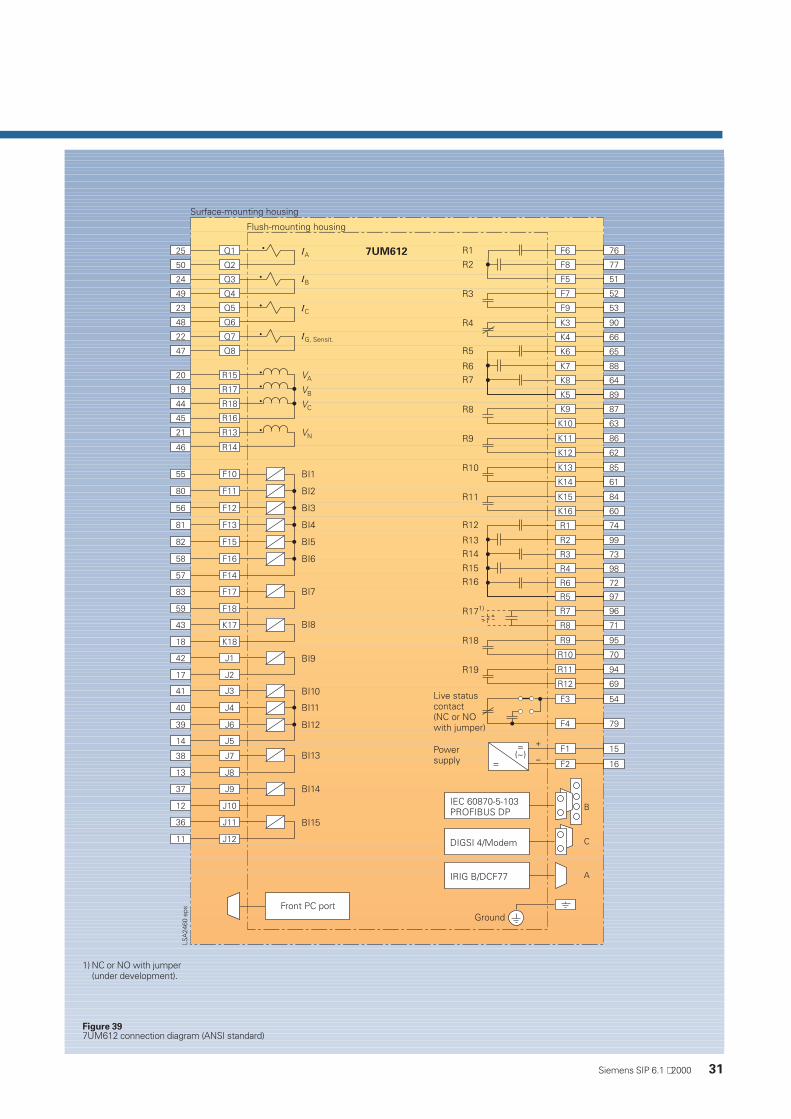
Figure 397UM612 connection diagram (ANSI standard)
1) NC or NO with jumper(under development).

SIPROTEC 4 7UM611/612Multifunction Generator Protection Relay
32 Siemens SIP 6.1 ⋅ 2000
Dimension drawings
Figure 407UM611 in 1/3 flush-mountinghousing 7XP20 forflush-mounting /cubicle-mounting
Figure 417UM611 in 1/3 surfacemounting housing 7XP20 forpanel surface mounting
RS232-interface
Side view Rear view 1Unit with screw-type terminals
Rear view 2Unit with plug-in terminals
FO
SUB-D-connector
Mounting plate
Panel cutout
Cutout 25 x 105(without paint)
FO case
Side viewFront view(without FO case)

Siemens SIP 6.1 ⋅ 2000 33
RS232-interface
Side view Rear view 1Unit with screw-type terminals
Rear view 2Unit with plug-in terminals
FO
SUB-D-connector
Mounting plate
Panel cutout
Figure 427UM612 in 1/2 flushmounting housing 7XP20 formounting /cubicle-mounting
Figure 437UM612 in 1/2 surfacemounting housing 7XP20 forpanel surface mounting
Side view Front view (without FO case)

Appendix
Catalog index of the Power Transmission and Distribution Group (Protection and Substation Control Systems Division)
Title Designation Order No.
Numerical Protective Relaying
Numerical Protection Devices LSA 2.0.1 E50001-K5702-A011-A1-7600Operation and Evaluation Software for Numerical Protection Devices LSA 2.0.2 E50001-K5702-A121-A1-7600Relay Selection Guide LSA 2.0.3 E50001-K5702-A031-A2-7600SIPROTEC 7SJ600 Overcurrent, Motor and Overload Protection LSA 2.1.15 E50001-K5712-A251-A2-7600SIPROTEC 7SJ601 Overcurrent Protection LSA 2.1.16 E50001-K5712-A261-A1-76007SJ41 Definite-Time Overcurrent Protection Relay LSA 2.1.10 E50001-K5712-A201-A2-76007SJ511 Numerical Overcurrent-Time Protection (Version V3) LSA 2.1.3 E50001-K5712-A131-A2-76007SJ512 Numerical Overcurrent-Time Protection (Version V3) LSA 2.1.4 E50001-K5712-A141-A3-76007SJ512 Numerical Feeder Protection (Version V3.6) LSA 2.1.30 E50001-K5712-A411-A1-4A00SIPROTEC 7SJ531 Numerical Line and Motor Protection withControl Function LSA 2.1.9 E50001-K5712-A191-A4-76007SJ551 Multi-Function Protection Relay LSA 2.4.2 E50001-K5742-A121-A3-7600SIPROTEC 4 7SJ61/62/63 6MD63 Multifunction Protection Relayand Bay Controller SIP 3.1 E50001-K4403-A111-A1-4A00SIPROTEC 7SJ602 Numerical Overcurrent, Motor and OverloadProtection Relay SIP 3.3 E50001-K4403-A131-A1-7600SIPROTEC 7SA510 Distance Protection Relay (Version V3) LSA 2.1.17 E50001-K5712-A271-A1-7600SIPROTEC 7SA511 Distance Protection Relay (Version V3) LSA 2.1.11 E50001-K5712-A211-A2-76007SA513 Line Protection Relay (Version V3) LSA 2.1.12 E50001-K5712-A221-A1-76007SA518/519 Overhead Control-Line Protection Relay (Version V3) LSA 2.1.14 E50001-K5712-A241-A2-76003VU13 Miniature Circuit-Breaker LSA 2.1.8 E50001-K5712-A181-A2-76007SD502 Line Differential Protection with Two Pilot Wires LSA 2.2.1 E50001-K5722-A111-A2-76007SD503 Line Differential Protection with Three Pilot Wires LSA 2.2.2 E50001-K5722-A121-A2-76007SD511/512 Current Comparison Protection Relay (Version V3)for Overhead Lines and Cables LSA 2.2.3 E50001-K5722-A131-A2-7600SIPRPOTEC 7SD60 Numerical Current Differential Protection Relayfor Two Pilot-Wire Link SIPROTEC 5.2 E50001-K4405-A121-A1-76007UT512/513 Differential Protection Relay (Version V3)for Transformers, Generators and Motors LSA 2.2.4 E50001-K5722-A141-A2-7600SIPROTEC 7SS50 Version V1.2 Busbar/Circuit-BreakerFailure Protection Relay (Summation Current Transformer Version) SIPROTEC 5.1 E50001-K4405-A111-A1-7600Auxiliary Current Transformers 4AM50, 4AM51, 4AM52and Isolating Transformers 7XR95 LSA 2.2.6 E50001-K5722-A161-A1-7600SIPROTEC 7SS52 Distributed Numerical Busbar and Circuit-BreakerFailure Protection Relay LSA 2.2.7 E50001-K5722-A171-A1-7600Introduction to Earth-Fault Detection LSA 2.3.1 E50001-K5732-A111-A2-76007SN71 Transient Earth-Fault Relay LSA 2.3.2 E50001-K5732-A121-A1-76007XR96 Toroidal Current Transformer LSA 2.3.3 E50001-K5732-A131-A1-76007VC1637 Earth-Leakage Monitor LSA 2.3.4 E50001-K5732-A141-A1-76007SK52 Motor Protection LSA 2.4.1 E50001-K5742-A111-A1-7600Introduction to Generator Protection LSA 2.5.1 E50001-K5752-A111-A1-76007UM511 Generator Protection Relay (Version V3) LSA 2.5.2 E50001-K5752-A121-A2-76007UM512 Generator Protection Relay (Version V3) LSA 2.5.3 E50001-K5752-A131-A2-76007UM515 Generator Protection Relay (Version V3) LSA 2.5.4 E50001-K5752-A141-A2-76007UM516 Generator Protection Relay (Version V3) LSA 2.5.5 E50001-K5752-A151-A1-7600SIPROTEC 4 7UM611/612 Multifunction Generator Protection Relay SIP 6.1 E50001-K4406-A111-A1-76007UW50 Tripping Matrix LSA 2.5.6 E50001-K5752-A161-A1-76007VE51 Synchronizing Unit LSA 2.5.7 E50001-K5752-A171-A1-76007VP151 Three-Phase Portable Test Set (Omicron CMC56) LSA 2.6.1 E50001-K5762-A111-A2-76007XV72 Test Switch LSA 2.6.2 E50001-K5762-A121-A1-76007SV50 Numerical Circuit-Breaker Failure Protection Relay LSA 2.7.1 E50001-K5772-A111-A1-76007SV512 Numerical Circuit-Breaker Failure Protection Relay LSA 2.7.2 E50001-K5772-A121-A1-76007VK512 Numerical Auto-Reclose/Check-Synchronism Relay LSA 2.7.3 E50001-K5772-A131-A1-76007SM70 Analog Output Unit LSA 2.7.5 E50001-K5772-A151-A1-76007SM71 Analog Output Unit LSA 2.7.6 E50001-K5772-A161-A1-76007SV7220 Power Supply Unit LSA 2.7.9 E50001-K5772-A191-A1-7600SIPROTEC 7RW600 Numerical Voltage, Frequency andOverexcitation Relay SIP 2.1 E50001-K4402-A111-A1-7600Communication for Protection DevicesCentralized and Remote Control of Siemens Protection Relays (Overview) SIPROTEC 8.1 E50001-K4408-A111-A1-7600DIGSI 4 - Software for Configuration and Operation of SIPROTEC 4 units SIP 8.2 E50001-K4408-A121-A1-7600DIGRA 4 - Software for the Visualization and Analysis of Fault Records SIP 8.3 E50001-K4408-A131-A1-7600Operating and Analysis Software DIGSI V3 LSA 2.8.2 E50001-K5782-A121-A1-76006MB252 Mini Bay Unit for Energy Automation with SICAM SIPROTEC 7.1 E50001-K4407-A111-A1-7600
Analog Protective Relaying
Static Analog Network Protection Relays R 1.1 E50001-K4501-A111-A1-7600Static Analog Machine Protection Relays R 1.2 E50001-K4501-A121-A1-7600Static Analog Ancillary Protection Equipment R 1.3 E50001-K4501-A131-A1-7600
34 Siemens SIP 6.1 ⋅ 2000

Catalog index
Title Designation Order No.
Energy Automation
Substation SICAM RTU System SICAM 2.1.1 E50001-K5602-A111-A1-7600SICAM miniRTU 6MD202 SubRTU SICAM 2.2.1 E50001-K5602-A211-A1-7600SICAM microRTU 6MD2030 Substation SICAM 2.3.1 E50001-K5602-A311-A1-7600SICAM SAS Substation Automation System SICAM 3.1.1 E50001-K5603-A111-A1-7600PS20A-6EP8090 Power Supply Module SICAM 5.1.1 E50001-K5605-A111-A1-7600DI32-6MD1021 Digital Input Functional Module SICAM 5.2.1 E50001-K5605-A211-A1-7600AI32-6MD1031 Analog Input Functional Module SICAM 5.2.2 E50001-K5605-A221-A1-7600AI16-6MD1032 Analog Input Functional Module SICAM 5.2.3 E50001-K5605-A231-A1-7600Visualization System for SICAM SAS: SICAM WinCC SICAM 6.1.1 E50001-K5606-A111-A1-7600SICAM plusTOOLS Configuration System SICAM 6.2.1 E50001-K5606-A211-A1-7600
Power QualityFault and Digital Recorder SIMEAS R SR 10.1.1 E50001-K4011-A101-A1-7600Central Fault Data Unit DAKON SR 10.1.2 see IntranetOSCOP P The Program for Power Quality Recorders SR 10.1.3 E50001-K4013-A101-A1-7600Power System Quality Analysis OSCILLOSTORE SR 10.2 E50001-K4020-A101-A1-7600SIMEAS Q Quality Recorder SR 10.2.5 E50001-K4025-A101-A1-7600SIMEAS P Power Meter SR 10.2.6 E50001-K4026-A101-A1-7600SIMEAS T Transducers for Power Variables SR 10.4 E50001-K4040-A101-A1-7600Active Filter and Power Conditioner for DistributionNetworks SIPCON P/S SR 10.5 E50001-K4050-A201-A1-7600Low Voltage Capacitors and Power Factor Correction Units SIPCON T SR 10.6 E50001-K4060-A101-A1-7600
Substation Control and Protection
Input/Output Unit 6MB522 LSA 1.1.1 E50001-K5701-A111-A4-7600Input/Output Unit 6MB523 LSA 1.1.2 E50001-K5701-A121-A2-76006MB511/6MB512 Substation Control Master Unit and7SW511/7SW512 Relay Data Concentrator LSA 1.1.3 E50001-K5701-A131-A2-76006MB520/6MB521 Input/Output Units LSA 1.1.4 E50001-K5701-A141-A1-76006MB513/514 Compact Control Master Unitand Relay Data Concentrator LSA 1.1.6 E50001-K5701-A161-A1-76006MB524 Bay Control Unit LSA 1.1.7 E50001-K5701-A171-A2-76006MB525 Mini Bay Unit (MBU) LSA 1.1.8 E50001-K5701-A181-A1-76006MB5510 Station Control Unit LSA 1.2.1 E50001-K5701-A211-A2-76006MB552 Compact Remote Terminal Unit LSA 1.2.2 E50001-K5701-A221-A1-76006MB5530-0 Minicompact Remote Terminal Unit LSA 1.2.3 E50001-K5701-A231-A1-76006MB5530-1 Minicompact Remote Terminal Unit forCable Shield Communication LSA 1.2.4 E50001-K5701-A241-A1-76006MB5540 SINAUT LSA COMPACT Remote Terminal Unit LSA 1.2.5 E50001-K5701-A251-A1-76006MB5515 Station Control Unit LSA 1.2.6 E50001-K5701-A261-A1-7600Control in SINAUT LSA Substation Control and Protection LSA 1.4.1 E50001-K5701-A411-A1-7600Status Indications in SINAUT LSA Substation Control and Protection LSA 1.4.2 E50001-K5701-A421-A1-7600Analog Values in SINAUT LSA Substation Control and Protection LSA 1.4.3 E50001-K5701-A431-A1-7600Metering in SINAUT LSA Substation Control and Protection LSA 1.4.4 E50001-K5701-A441-A1-7600Voltage Control with Input/Output Units 6MB520/6MB521 LSA 1.4.5 E50001-K5701-A451-A1-7600Network Synchronization with Input/Output Units 6MB520/521 LSA 1.4.6 E50001-K5701-A461-A1-7600Operation with Two Control Master Units LSA 1.4.7 E50001-K5701-A471-A1-7600Node Functions in SINAUT LSA Substation Control and Protection LSA 1.4.8 E50001-K5701-A481-A1-7600System Management with the SINAUT LSA Substation Controland Protection System LSA 1.4.9 E50001-K5701-A491-A1-7600LSADIAG - Testing and Diagnostics System for SINAUT LSA LSA 1.5.2 E50001-K5701-A521-A1-7600Substation Control and ProtectionLSACONTROL - Control and Monitoring LSA 1.5.3 E50001-K5701-A531-A1-7600LSAPROCESS - Process Information Analysis LSA 1.5.5 E50001-K5701-A551-A1-7600LSA 678 Standard Cubicle LSA 1.6.1 E50001-K5701-A611-A1-7600
Siemens SIP 6.1 ⋅ 2000 35

Conditions of Sale and Delivery
Export Regulations Trademarks
Subject to theGeneral Conditions of Supplyand Deliveryfor Products and Services ofthe Electrical and ElectronicIndustry and to any otherconditions agreed upon withthe recipients of catalogs.
The technical data, dimensionsand weights are subject tochange unless otherwisestated on the individual pagesof this catalog.The illustrations are for refer-ence only.
We reserve the right to adjustthe prices and shall charge theprice applying on the date ofdelivery
In accordance with presentprovisions of the GermanExport List and the USCommercial Control List,export licences are notrequired for the productslisted in this catalog.
An export licence mayhowever be required due tocountry-specific application andfinal destination of the products.Relevant are the export criteriastated in the delivery note andthe invoice regarding a possibleexport and reexport licence.Subject to change withoutnotice.
All dimensions in this catalogare given in mm.
Dimensions
All product designations usedare trademarks or productnames of Siemens AG or ofother suppliers.
Responsible forTechnical contents:Dr. Hans-Joachim HerrmannSiemens AG, EV S V13, NürnbergGeneral editing: Claudia Kühn-SutionoSiemens AG, EV BK T, Erlangen
Order No.: E50001-K4406-A111-A1-7600Printed in GermanyKGK 0700 5.0 36 En 101753 6101/D6111
36 Siemens SIP 6.1 ⋅ 2000

www.ev.siemens.de/index_e.htm Order No.: E50001-K4406-A111-A1-7600
Published by
Siemens AktiengesellschaftPower Transmission and Distribution GroupProtection and Substation Control Systems DivisionPostfach 48 0690026 NürnbergDEUTSCHLAND