Embed Size (px)
Citation preview

TECHNICAL MANUAL A100K11211
CONFIGURATION GUIDE
SIP Master Stations
Zenitel Norway AS and its subsidiaries assume no responsibilities for any errors that may appear in this publication, or for damages arising from the information in it. No information in this publication should be regarded as a warranty made by Zenitel Norway AS.
The information in this publication may be revised or changed without notice. Product names mentioned in this publication may be trademarks of others and are used only for identification.
Zenitel Norway AS © 2012
About this Document
Document ScopeThis document describes the configuration of the STENTOFON SIP Master Stations.
Publication LogRev. Date Author Status1.0 19.1.2012 HKL published
Related DocumentationFor further information, refer to the following documentation:
Doc. no. Documentation
A100K10788 IP Master Station Installation & Configuration
A100K10935 IP Master Station Getting Started
A100K10812 SIP Substation Installation & Configuration
3SIP Master Stations ConfigurationA100K11211
Contents1 Introduction .....................................................................................................................4
1.1 IP Desktop Master Station ........................................................................................41.2 IP OR Master Station ................................................................................................51.3 IP Flush Master Station .............................................................................................51.4 IP Dual Display Station .............................................................................................5
2 SIPConfiguration ...........................................................................................................62.1 Configuration Via Station Keypad .............................................................................62.2 SIP Station Web Interface ........................................................................................72.3 Station Main Settings ...............................................................................................82.4 SIP Settings ..............................................................................................................82.5 Audio Settings ......................................................................................................... 112.6 Direct Access Key Settings .....................................................................................122.7 SNMP Settings ........................................................................................................132.8 Automatic Configuration using TFTP ....................................................................152.9 Advanced Configuration Options ............................................................................16
2.9.1 VLAN ..............................................................................................................162.9.2 Network Access Control .................................................................................18
3 Software Upgrade .........................................................................................................193.1 TFTP Server Program .............................................................................................193.2 Manual Software Upgrade ......................................................................................193.3 Automatic Software Upgrade .................................................................................20
4 Station Board Connections .........................................................................................22
5 Station Indication LEDs ...............................................................................................255.1 Station LED .............................................................................................................255.2 Status LED ..............................................................................................................255.3 Power LED ..............................................................................................................265.4 LAN LEDs ...............................................................................................................26
6 Restoring Factory Defaults ..........................................................................................27
7 ConfigurationFileParameters ....................................................................................287.1 Remote Provisioning using TFTP ..........................................................................287.2 General Parameters ...............................................................................................287.3 SIP Parameters ......................................................................................................297.4 Call Parameters .....................................................................................................307.5 SNMP Parameters .................................................................................................327.6 Example Configuration Files ...................................................................................34
7.6.1 Device Specific Configuration File .................................................................347.6.2 Global Configuration File ...............................................................................35
FiguresFigure 1 SIP System Configuration ..................................................................................................... 4Figure 2 RJ45 Ports at Rear of IP Desktop Master Station ................................................................ 7Figure 3 RJ45 Port at Bottom of IP Dual Display Station .................................................................... 7Figure 4 RJ45 Ports on IP Flush/OR Master Stations ........................................................................ 7Figure 5 Station Board Connections ................................................................................................. 22

4 A100K11211SIP Master Stations Configuration
1 Introduction
SIP (Session Initiation Protocol) is the de facto standard for IP telephony. The STENTOFON SIP intercom stations are specially built for easy integration with any iPBX system.
The STENTOFON SIP Stations are custom-made IP intercom stations that can integrate with any iPBX system.
Figure 1 SIP System Configuration
1.1 IP Desktop Master Station item nos. 1008001000 (with handset), 1008000000 (without handset)
The IP Desktop Master is a general purpose intercom station featuring a large high contrast display with backlight showing crystal clear information. Ten direct access keys (DAK) provide single-touch access to other stations, group calls, audio monitoring, public address zones, radio channels and/or the opening of doors and gates.
The station connects directly to the IP network, making it easy to deploy anywhere at any distance. The built-in web server allows monitoring, configuration and software updates over the IP network for easy maintenance of remote stations.
IP Network
SIP Dual Display
SIP OR Master
SIP Desk Master
iPBX (SIP domain)
SIP phone
SIP phone
5SIP Master Stations ConfigurationA100K11211
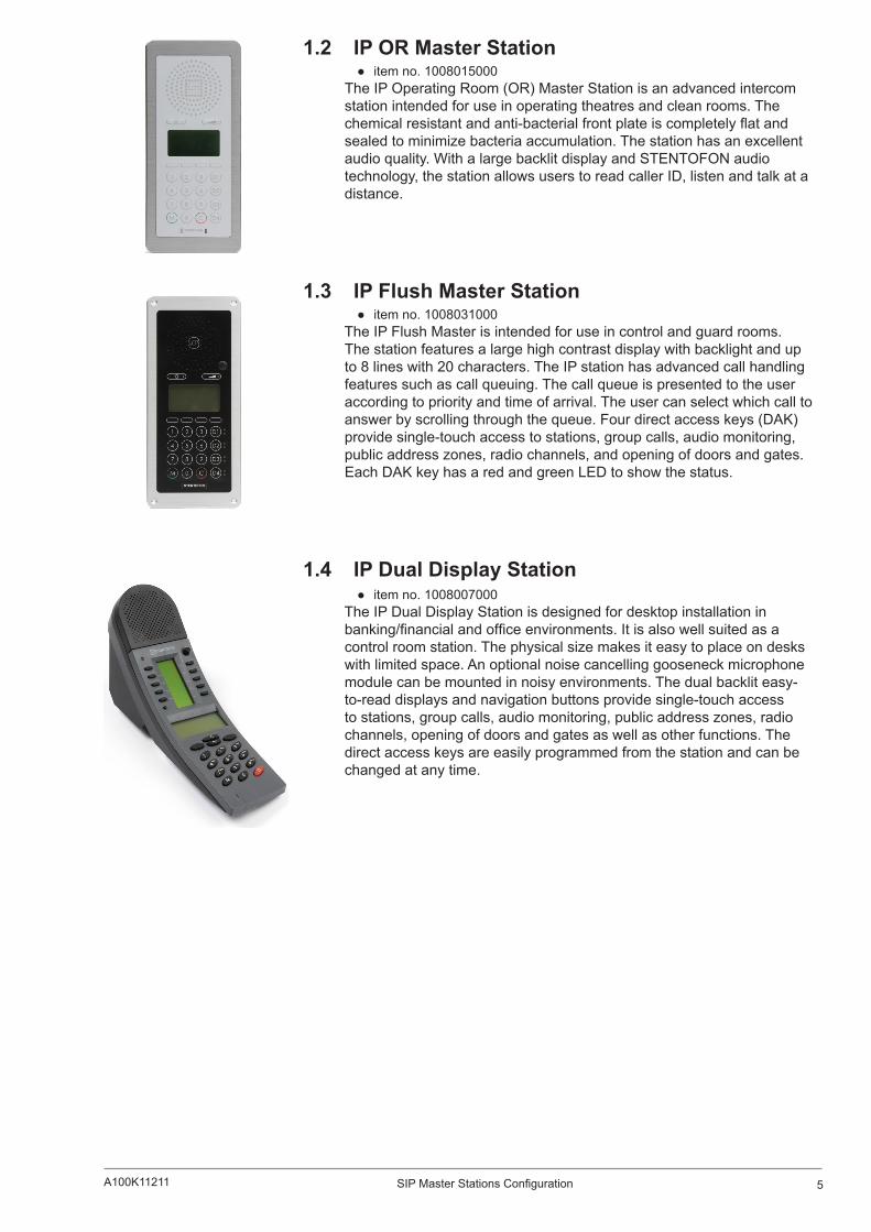
1.2 IP OR Master Station item no. 1008015000
The IP Operating Room (OR) Master Station is an advanced intercom station intended for use in operating theatres and clean rooms. The chemical resistant and anti-bacterial front plate is completely flat and sealed to minimize bacteria accumulation. The station has an excellent audio quality. With a large backlit display and STENTOFON audio technology, the station allows users to read caller ID, listen and talk at a distance.
1.3 IP Flush Master Station item no. 1008031000
The IP Flush Master is intended for use in control and guard rooms. The station features a large high contrast display with backlight and up to 8 lines with 20 characters. The IP station has advanced call handling features such as call queuing. The call queue is presented to the user according to priority and time of arrival. The user can select which call to answer by scrolling through the queue. Four direct access keys (DAK) provide single-touch access to stations, group calls, audio monitoring, public address zones, radio channels, and opening of doors and gates. Each DAK key has a red and green LED to show the status.
1.4 IP Dual Display Station item no. 1008007000
The IP Dual Display Station is designed for desktop installation in banking/financial and office environments. It is also well suited as a control room station. The physical size makes it easy to place on desks with limited space. An optional noise cancelling gooseneck microphone module can be mounted in noisy environments. The dual backlit easy-to-read displays and navigation buttons provide single-touch access to stations, group calls, audio monitoring, public address zones, radio channels, opening of doors and gates as well as other functions. The direct access keys are easily programmed from the station and can be changed at any time.
6 A100K11211SIP Master Stations Configuration
2 SIPConfigurationThere are two ways of configuring the IP Master Station for SIP:
Using the station keypad Using a web browser
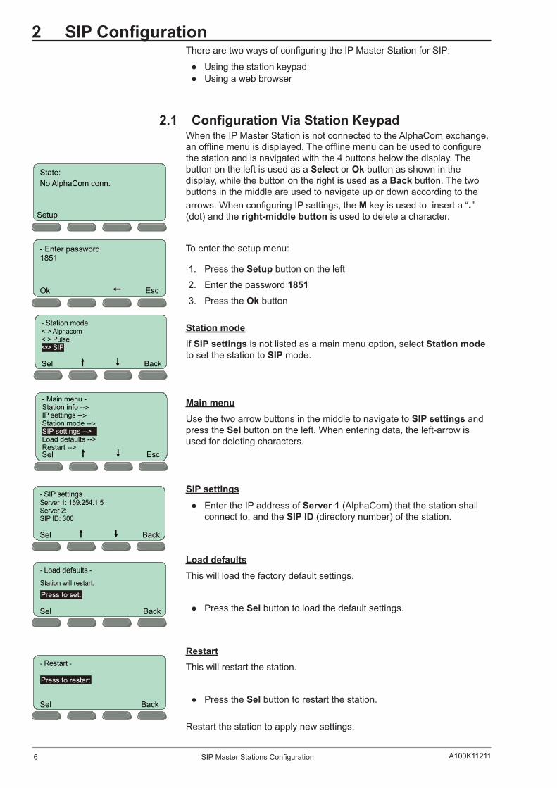
2.1 ConfigurationViaStationKeypadWhen the IP Master Station is not connected to the AlphaCom exchange, an offline menu is displayed. The offline menu can be used to configure the station and is navigated with the 4 buttons below the display. The button on the left is used as a Select or Ok button as shown in the display, while the button on the right is used as a Back button. The two buttons in the middle are used to navigate up or down according to the arrows. When configuring IP settings, the M key is used to insert a “.” (dot) and the right-middle button is used to delete a character.
To enter the setup menu:
1. Press the Setup button on the left
2. Enter the password 18513. Press the Ok button
Station modeIf SIP settings is not listed as a main menu option, select Station mode to set the station to SIP mode.
Main menuUse the two arrow buttons in the middle to navigate to SIP settings and press the Sel button on the left. When entering data, the left-arrow is used for deleting characters.
SIP settings
Enter the IP address of Server 1 (AlphaCom) that the station shall connect to, and the SIP ID (directory number) of the station.
Load defaultsThis will load the factory default settings.
Press the Sel button to load the default settings.
RestartThis will restart the station.
Press the Sel button to restart the station.
Restart the station to apply new settings.
No AlphaCom conn.
Setup
State:
- Enter password1851
Ok Esc
BackSel
*
Sel Esc
- Main menu -Station info -->IP settings -->Station mode -->
Load defaults -->Restart -->
SIP settings -->
BackSel
BackSel
Press to set.
BackSel
Press to restart
7SIP Master Stations ConfigurationA100K11211
2.2 SIP Station Web Interface The SIP Station features an embedded web server, which allows users to log in via a standard web browser.
At commissioning, the SIP Station needs to be configured to make it possible for the SIP Station to register in the iPBX system.
To do this, your PC and the IP station have to be connected together via a PoE switch using network cables:
Connect the PC to the PoE switch Connect the LAN port on the SIP station to the PoE switch
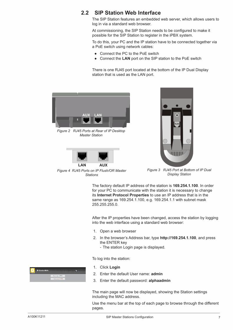
There is one RJ45 port located at the bottom of the IP Dual Display station that is used as the LAN port.
Figure 2 RJ45 Ports at Rear of IP Desktop Master Station
RJ45
Figure 3 RJ45 Port at Bottom of IP Dual Display Station
Figure 4 RJ45 Ports on IP Flush/OR Master Stations
The factory default IP address of the station is 169.254.1.100. In order for your PC to communicate with the station it is necessary to change its Internet Protocol Properties to use an IP address that is in the same range as 169.254.1.100, e.g. 169.254.1.1 with subnet mask 255.255.255.0.
After the IP properties have been changed, access the station by logging into the web interface using a standard web browser:
1. Open a web browser
2. In the browser’s Address bar, type http://169.254.1.100, and press the ENTER key - The station Login page is displayed.
To log into the station:
1. Click Login 2. Enter the default User name: admin3. Enter the default password: alphaadmin
The main page will now be displayed, showing the Station settings including the MAC address.
Use the menu bar at the top of each page to browse through the different pages.
LANAUX
LAN AUX
8 A100K11211SIP Master Stations Configuration
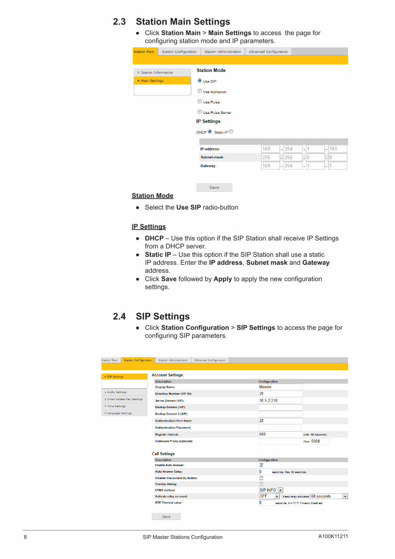
2.3 Station Main Settings Click Station Main > Main Settings to access the page for
configuring station mode and IP parameters.
Station Mode
Select the Use SIP radio-button
IP Settings
DHCP – Use this option if the SIP Station shall receive IP Settings from a DHCP server.
Static IP – Use this option if the SIP Station shall use a static IP address. Enter the IP address, Subnet mask and Gateway address.
Click Save followed by Apply to apply the new configuration settings.
2.4 SIP Settings Click StationConfiguration > SIP Settings to access the page for
configuring SIP parameters.

9SIP Master Stations ConfigurationA100K11211
Account SettingsDisplay Name
- Enter a name that will be shown on the display at the remote party.
Directory Number (SIP ID) - This is the identification of the station in the SIP domain, i.e. the phone number for the station. This parameter is mandatory. Enter the SIP ID in integers according to the SIP account on the SIP domain server.
Server Domain (SIP) - This parameter is mandatory and specifies the primary domain for the station and is the IP address for the SIP server (e.g. Asterisk or Cisco Call Manager). Enter the IP address in regular dot notation, e.g. 10.5.2.138.
Backup Domain (SIP) - This is the secondary (or fallback) domain. If the station loses connection to the primary SIP domain, it will switch over to the secondary one. Enter the IP address in regular dot notation.
Backup Domain 2 (SIP) - This is the tertiary backup domain.
Authentication User Name - This is the authentication user name used to register the station to the SIP server. This is required only if the SIP server requires authentication and is normally the same as the SIP ID.
Authentication Password - The authentication user password used to register the station to the SIP server. This is required only if the SIP server requires authentication
Register interval - This parameter specifies how often the station will register, and reregister in the SIP domain. This parameter will affect the time it takes to detect that a connection to a SIP domain is lost.
- Enter the values in number of seconds from 60 to 999999. The default interval is 600 seconds.
Outbound Proxy [optional] - Enter the IP address of the outbound proxy server in regular dot notation, e.g. 10.5.2.100
Port - Enter the port number used for SIP on the outbound proxy server. The default port number is 5060.
Call SettingsEnable Auto Answer
- This is not required. Enables automatic answer after a set number of seconds.
10 A100K11211SIP Master Stations Configuration
- Check the checkbox to enable this function and enter the delay in seconds in the field for Auto Answer Delay. The default delay setting is 0 and the maximum is 30 seconds.
Disable Disconnect By Button - This disables disconnect with the speed dial during and when setting up a conversation. Check the checkbox to enable this function.
Overlap dialing - This will lead to the phone starting to dial each time a digit is entered and the SIP proxy replying with ‘Number incomplete’ until such time as the number has been entered and the call can be initiated successfully without the enter key having to be pressed.
DTMF method - Choose between SIP INFO or RFC 2833 to select DTMF signalling method.
Activate relay on event - When enabled, the station will activate the relay when receiving the specified DTMF character in the RTP stream. Select from the dropdown menu. Options are OFF, 1-9, *, In call or Ringing. The default setting is OFF.
- Select the number of seconds to keep the relay open in the range 1 to 240 from the dropdown menu. The default setting is 60 seconds.
- Options are: 1 - 240 seconds, during call, during ringing, until DTMF # or 0.
RTP Timeout value - This cancels a call if the station does not receive RTP packets from the remote party. Enter values in the range 0-9999 seconds. The default setting is 0 which means RTP timeout is disabled.
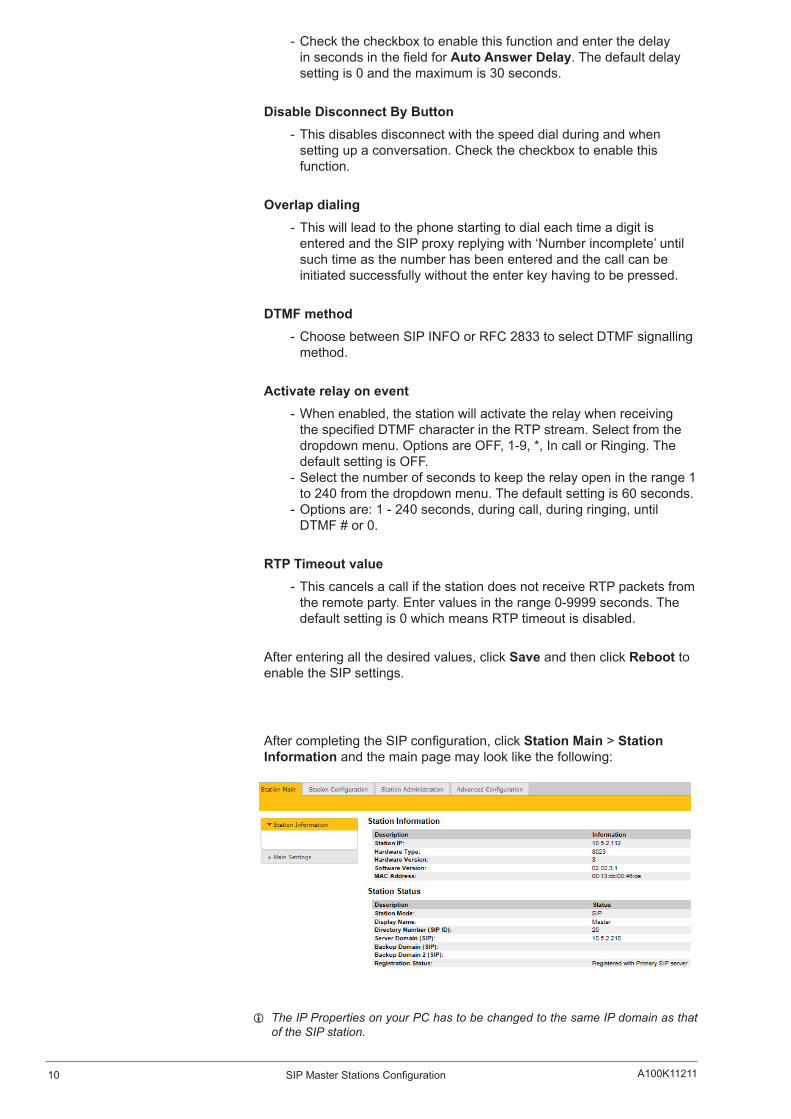
After entering all the desired values, click Save and then click Reboot to enable the SIP settings.
After completing the SIP configuration, click Station Main > Station Information and the main page may look like the following:
L The IP Properties on your PC has to be changed to the same IP domain as that of the SIP station.
11SIP Master Stations ConfigurationA100K11211
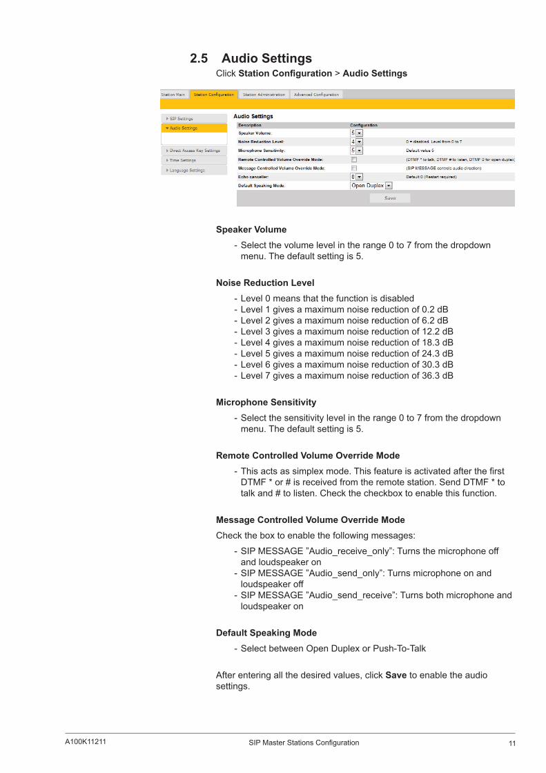
2.5 Audio SettingsClick StationConfiguration > Audio Settings
SpeakerVolume - Select the volume level in the range 0 to 7 from the dropdown menu. The default setting is 5.
Noise Reduction Level - Level 0 means that the function is disabled - Level 1 gives a maximum noise reduction of 0.2 dB - Level 2 gives a maximum noise reduction of 6.2 dB - Level 3 gives a maximum noise reduction of 12.2 dB - Level 4 gives a maximum noise reduction of 18.3 dB - Level 5 gives a maximum noise reduction of 24.3 dB - Level 6 gives a maximum noise reduction of 30.3 dB - Level 7 gives a maximum noise reduction of 36.3 dB
Microphone Sensitivity - Select the sensitivity level in the range 0 to 7 from the dropdown menu. The default setting is 5.
RemoteControlledVolumeOverrideMode - This acts as simplex mode. This feature is activated after the first DTMF * or # is received from the remote station. Send DTMF * to talk and # to listen. Check the checkbox to enable this function.
MessageControlledVolumeOverrideModeCheck the box to enable the following messages:
- SIP MESSAGE ”Audio_receive_only”: Turns the microphone off and loudspeaker on
- SIP MESSAGE ”Audio_send_only”: Turns microphone on and loudspeaker off
- SIP MESSAGE ”Audio_send_receive”: Turns both microphone and loudspeaker on
Default Speaking Mode - Select between Open Duplex or Push-To-Talk
After entering all the desired values, click Save to enable the audio settings.
12 A100K11211SIP Master Stations Configuration
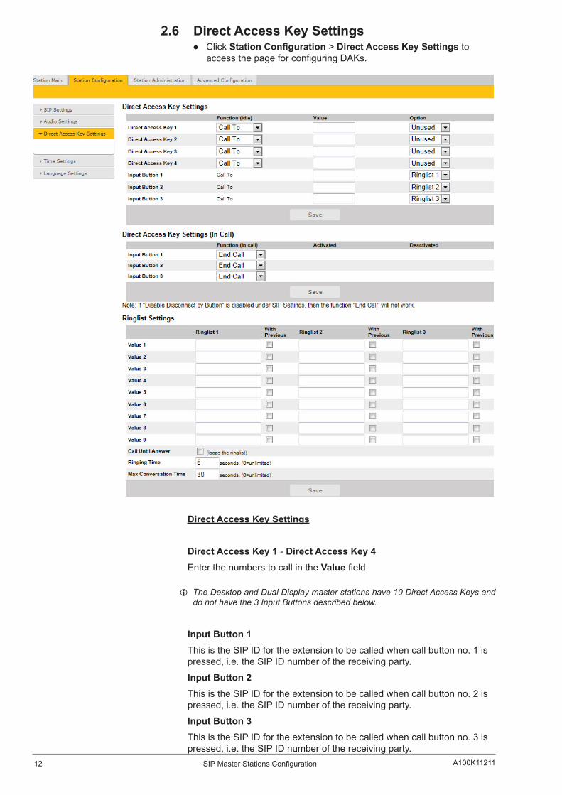
2.6 DirectAccessKeySettings Click StationConfiguration > DirectAccessKeySettings to
access the page for configuring DAKs.
DirectAccessKeySettings
DirectAccessKey1-DirectAccessKey4Enter the numbers to call in the Value field.
L The Desktop and Dual Display master stations have 10 Direct Access Keys and do not have the 3 Input Buttons described below.
Input Button 1This is the SIP ID for the extension to be called when call button no. 1 is pressed, i.e. the SIP ID number of the receiving party.
Input Button 2This is the SIP ID for the extension to be called when call button no. 2 is pressed, i.e. the SIP ID number of the receiving party.
Input Button 3This is the SIP ID for the extension to be called when call button no. 3 is pressed, i.e. the SIP ID number of the receiving party.
13SIP Master Stations ConfigurationA100K11211
DirectAccessKeySettings(InCall) - Select input buttons 1 - 3 for direct access calls while in conversation.
- Options are: End Call, Do Nothing, Send Text, Send DTMF
L Pin connections for the three input buttons are located on the P4 connector. See Section 4: Station Board Connections for more information.
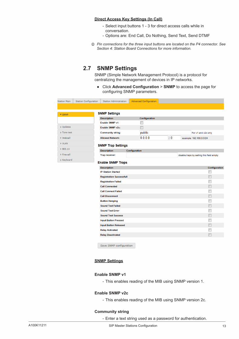
2.7 SNMP SettingsSNMP (Simple Network Management Protocol) is a protocol for centralizing the management of devices in IP networks.
Click AdvancedConfiguration > SNMP to access the page for configuring SNMP parameters.
SNMP Settings
Enable SNMP v1 - This enables reading of the MIB using SNMP version 1.
Enable SNMP v2c - This enables reading of the MIB using SNMP version 2c.
Community string - Enter a text string used as a password for authentication.
14 A100K11211SIP Master Stations Configuration
Allowed Network - This is used, together with the network mask, to determine the allowed network for reading the MIB on the station.
- The IP address is entered in regular dot notation, e.g. 10.5.2.100. For example with an allowed network 10.5.2.0 and a network mask of 24, any station with an IP address in the range 10.5.2.0 to 10.5.2.255 can access the MIB.
SNMP Trap Settings
Trap receiver - Enter the IP address of the server receiving SNMP traps. This is disabled if the field is left empty.
Enable SNMP Traps
ipsStarted - If enabled, the station will send an SNMP trap when the station application is started.
sipRegistered - If enabled, the station will send an SNMP trap when successfully registered in the SIP domain.
sipRegisterFailed - If enabled, the station will send an SNMP trap if registration in the SIP domain failed.
callConnect - If enabled, the station will send an SNMP trap when a call is connected.
callConnectFailed - If enabled, the station will send an SNMP trap if a call to the station fails to connect for any reason (busy etc.).
callDisconnect - If enabled, the station will send an SNMP trap when a call is disconnected.

15SIP Master Stations ConfigurationA100K11211
2.8 AutomaticConfigurationusingTFTPA SIP station may be set up to automatically poll configuration settings for SIP, Call and SNMP from a TFTP server. The IP address of this TFTP server can be obtained using DHCP procedures or be manually configured.
Before you start the automatic configuration procedure:
A configuration file should first be created. The relevant parameters for SIP, Call and SNMP in the configuration file are described in Section 7: Configuration File Parameters.
Follow the procedures described in Section 3.1: TFTP Server Program.
To carry out automatic configuration from the station web server:
1. Start the TFTP server program and set the server path by browsing to the directory where the configuration file is located.
2. Log on to the SIP Station web server.
3. SelectAdvancedConfiguration > Updates
4. Under ConfigurationUpdates select the radio button for Automatic5. Either select the radio button for From DHCP or enter the IP address
of the TFTP server (your PC IP address)
6. Under Automatic Update Interval enter the interval in minutes for checking updates. - The value must be between 1 and 999 and the default setting is 60.
7. Click Saveconfigurationfor“Updates”
The station will now contact the TFTP server and run the configuration file to carry out the configuration procedure according to the set time interval.

16 A100K11211SIP Master Stations Configuration
2.9 AdvancedConfigurationOptions L The configuration settings described in this section are not mandatory.
2.9.1 VLANVLAN Tagging or IEEE 802.1Q is a networking standard allowing multiple bridged networks to transparently share the same physical network link without leakage of information between networks. IEEE 802.1Q — along with its shortened form dot1q — is commonly used to refer to the encapsulation protocol used to implement this mechanism over Ethernet networks.
L STENTOFON IP Stations support 802.1Q as from firmware version 01.09.3.0.
User interfaceVLAN is configured in the IP station web interface.
Select AdvancedConfiguration > VLAN from the menu
Clicking the Apply settings button will apply the chosen settings. With the exception of a restart, the saved settings will not come into effect until Apply settings is clicked.
EnableVLANThis option determines whether the switch uses 802.1Q or not. If this is enabled, the switch is VLAN aware. Select YES or NO from the dropdown menu.
PortspecificVLANrulesandtaggingoptionsHere, it is possible to specify which VLAN ID and priority the ports should assign untagged packets to. Tagged packets are not changed.

17SIP Master Stations ConfigurationA100K11211
VLANID has a value range from 0 to 4094. It specifies which VLAN ID tag to add to a packet.
VLANpriority has a value range from 0 to 7. It specifies which VLAN priority tag to add to a packet.
Sendingfilter specifies whether a given port will only send to VLANs which it is a member of or all VLANs. For example, if the chosen option is MEMBERS then a packet with VLAN ID 1 at the LAN port will only reach another port which is a member of VLAN ID 1. Select MEMBERS or ALL from the dropdown menu.
Acceptancefilter specifies whether a port will accept only tagged packets or all packets. The option ONLY TAGGED should only be used against VLAN aware devices which tag packets. Select ONLY TAGGED or ALL from the dropdown menu.
VLANprioritytagtoswitchpriorityHere, it is possible to specify how the switch should queue the packets with VLANprioritytag.
Switch priority: Select HIGH or LOW from the dropdown menu. By default, packets with VLAN priority tags from 4 to 7 are set to the HIGH priority queue.
AddportstoaVLANHere, it is possible to determine whether the ports should be members of the specified VLAN. There is also a setting for specifying whether the ports should strip or keep the VLAN tag when sending egress packets.
Membership determines whether the port is a member of the specified VLAN or not. Select Not member or Member from the dropdown menu.
Egress tagging determines whether the port should remove VLAN tags or keep them for the specified VLAN. Select Remove tag or Keeptag from the dropdown menu.
Clicking the AddVLAN button will add the current chosen settings to the VLANtable below. If a VLAN in the VLANtable already exists with the chosen VLANID, then the settings will be updated.
RemoveVLANbyIDHere, it is possible to determine which VLAN is to be removed from the VLANtable by specifying the VLANID, then clicking the RemoveVLANbutton.
VLANtableThe VLANs that the ports are members of are listed under the Membership Info column. The table also lists the ports that keep the VLAN tag when sending egress packets; this is shown under the Egress Tagging Info column. The VLANtable can accommodate a maximum of 63 VLANs.
L The DHCP address is received before the switch is VLAN aware (during startup). Either trunk all VLANs or set the DHCP server which should reach the IP station on a native VLAN.
18 A100K11211SIP Master Stations Configuration
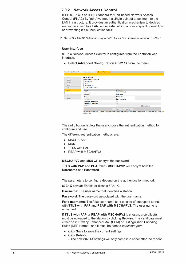
2.9.2 Network Access ControlIEEE 802.1X is an IEEE Standard for Port-based Network Access Control (PNAC) By “port” we mean a single point of attachment to the LAN infrastructure. It provides an authentication mechanism to devices wishing to attach to a LAN, either establishing a point-to-point connection or preventing it if authentication fails.
L STENTOFON SIP Stations support 802.1X as from firmware version 01.09.3.0.
User interface 802.1X Network Access Control is configured from the IP station web interface.
Select AdvancedConfiguration > 802.1X from the menu.
The radio button list lets the user choose the authentication method to configure and use.
The different authentication methods are:
MSCHAPV2 MD5 TTLS with PAP PEAP with MSCHAPV2
MSCHAPV2 and MD5 will encrypt the password.
TTLS with PAP and PEAPwithMSCHAPV2 will encrypt both the Username and Password.
The parameters to configure depend on the authentication method:
802.1X status: Enable or disable 802.1X.
Username: The user name that identifies a station.
Password: The password associated with the user name.
Fake username: The fake user name sent outside of encrypted tunnel with TTLS with PAP and PEAPwithMSCHAPV2. The user name is encrypted.
If TTLS with PAP or PEAPwithMSCHAPV2 is chosen, a certificate must be uploaded to the station by clicking Browse. The certificate must either be in Privacy Enhanced Mail (PEM) or Distinguished Encoding Rules (DER) format, and it must be named certificate.pem.
Click Save to save the current settings Click Reboot
- The new 802.1X settings will only come into effect after the reboot.

19SIP Master Stations ConfigurationA100K11211
3 Software UpgradeSoftware upgrade is carried out via the web server of the station.
There are two ways of upgrading the software on the SIP station:
Manual Upgrade Automatic Upgrade
3.1 TFTP Server ProgramBoth upgrade methods require that an TFTP Server is available and that the latest software image file has been downloaded from Zenitel’s support website (AlphaWiki). During the upload process, the IP station will connect to the TFTP Server and download the software. The TFTP Server program must already be installed on your PC/server with a defined IP address. A free TFTP Server program can be downloaded from http://tftpd32.jounin.net. Before starting the IP station upgrade procedure, the TFTP Server program must be running and the directory where the software image file is located must be selected by using the Browse button in the program interface.
3.2 Manual Software UpgradeTo carry out a manual software upgrade from the station web server:
1. Start the TFTP server program and set the server path by browsing to the directory where the software file is located.
2. Log on to the SIP Station web server.
3. Select Station Administration > Manual Upgrade
4. Enter the IP address of the TFTP server (your PC IP address)
20 A100K11211SIP Master Stations Configuration
5. Enter the name of the software Imagefile (include bin file extension)
6. Enter the CRC checksum (found in the text file from the downloaded software package)
7. Click Save settings to store the data
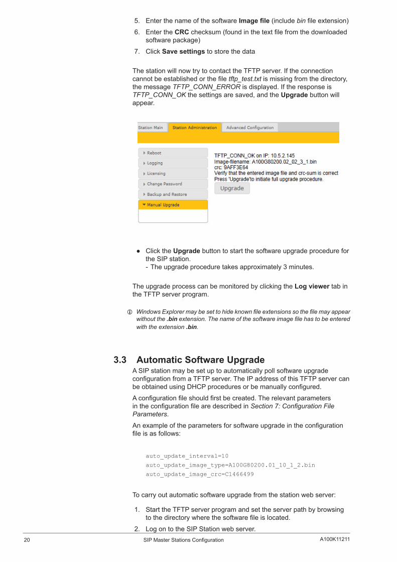
The station will now try to contact the TFTP server. If the connection cannot be established or the file tftp_test.txt is missing from the directory, the message TFTP_CONN_ERROR is displayed. If the response is TFTP_CONN_OK the settings are saved, and the Upgrade button will appear.
Click the Upgrade button to start the software upgrade procedure for the SIP station. - The upgrade procedure takes approximately 3 minutes.
The upgrade process can be monitored by clicking the Log viewer tab in the TFTP server program.
L Windows Explorer may be set to hide known file extensions so the file may appear without the .bin extension. The name of the software image file has to be entered with the extension .bin.
3.3 Automatic Software Upgrade A SIP station may be set up to automatically poll software upgrade configuration from a TFTP server. The IP address of this TFTP server can be obtained using DHCP procedures or be manually configured.
A configuration file should first be created. The relevant parameters in the configuration file are described in Section 7: Configuration File Parameters.
An example of the parameters for software upgrade in the configuration file is as follows:
auto_update_interval=10
auto_update_image_type=A100G80200.01_10_1_2.bin
auto_update_image_crc=C1466499
To carry out automatic software upgrade from the station web server:
1. Start the TFTP server program and set the server path by browsing to the directory where the software file is located.
2. Log on to the SIP Station web server.
21SIP Master Stations ConfigurationA100K11211
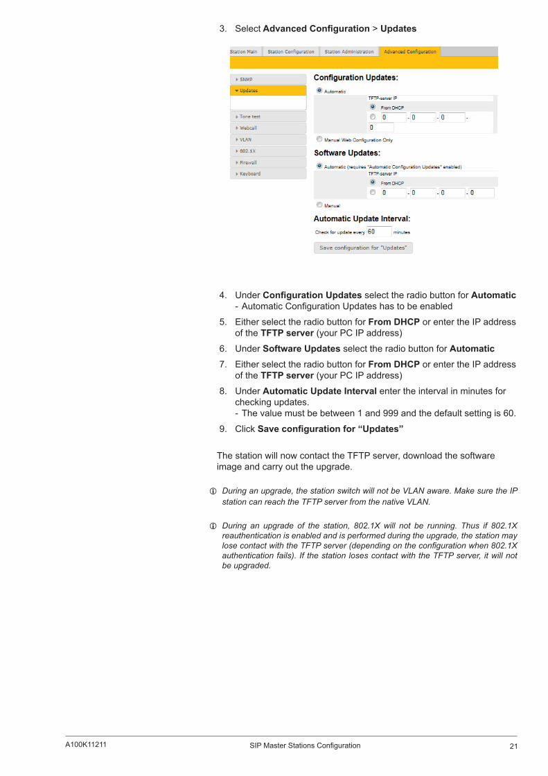
3. SelectAdvancedConfiguration > Updates
4. Under ConfigurationUpdates select the radio button for Automatic - Automatic Configuration Updates has to be enabled
5. Either select the radio button for From DHCP or enter the IP address of the TFTP server (your PC IP address)
6. Under Software Updates select the radio button for Automatic7. Either select the radio button for From DHCP or enter the IP address
of the TFTP server (your PC IP address)
8. Under Automatic Update Interval enter the interval in minutes for checking updates. - The value must be between 1 and 999 and the default setting is 60.
9. Click Saveconfigurationfor“Updates”
The station will now contact the TFTP server, download the software image and carry out the upgrade.
L During an upgrade, the station switch will not be VLAN aware. Make sure the IP station can reach the TFTP server from the native VLAN.
L During an upgrade of the station, 802.1X will not be running. Thus if 802.1X reauthentication is enabled and is performed during the upgrade, the station may lose contact with the TFTP server (depending on the configuration when 802.1X authentication fails). If the station loses contact with the TFTP server, it will not be upgraded.
22 A100K11211SIP Master Stations Configuration
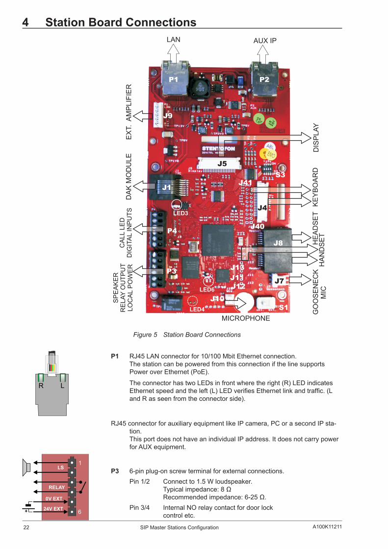
4 Station Board Connections
Figure 5 Station Board Connections
P1 RJ45 LAN connector for 10/100 Mbit Ethernet connection.The station can be powered from this connection if the line supports Power over Ethernet (PoE).
The connector has two LEDs in front where the right (R) LED indicates Ethernet speed and the left (L) LED verifies Ethernet link and traffic. (L and R as seen from the connector side).
RJ45 connector for auxiliary equipment like IP camera, PC or a second IP sta-tion.This port does not have an individual IP address. It does not carry power for AUX equipment.
P3 6-pin plug-on screw terminal for external connections. Pin 1/2 Connect to 1.5 W loudspeaker.
Typical impedance: 8 Ω Recommended impedance: 6-25 Ω.
Pin 3/4 Internal NO relay contact for door lock control etc.
P1
J9
J8
J1
J7
P3
P4
J4
J5
J41
J40
J10S1
S3
J12J11
J13
P2
LAN AUX IP
EX
T. A
MP
LIF
IER
KE
YB
OA
RD
GO
OS
EN
EC
K M
ICD
ISP
LA
Y
DA
K M
OD
ULE
HA
ND
SE
TH
EA
DS
ET
LED6
LED3
LED4
MICROPHONE
CA
LL L
ED
DIG
ITA
L I
NP
UT
S
SP
EA
KE
RR
EL
AY
OU
TP
UT
LO
CA
L P
OW
ER
LR
LS
RELAY
0VEXT
24VEXT+
1
6

23SIP Master Stations ConfigurationA100K11211
Pin 5/6 Connect 24 VDC for station power if PoE is not used. Pin 6 is positive.
P4 6-pin plug-on screw terminal for external connections. Pin 1/4 Input 1
Pin 2/4 Input 2 Pin 3/4 Input 3 Pin 5/6 Station LED for call message info.
J4 18-pin ZIF-connector for keyboard.The keyboard may have up to 10 dialling keys, M and C keys, 10 DAK keys, 10 soft keys, volume up/down and light dim up/down keys connected in a matrix according to the drawing.
J40 Optional keyboard connection.
J41 Optional DAK LED connection.Connection to J40/J41 can either be to a pin header or soldered directly to holes in the PCB.
J4 & J40 pin1-9 Keyboard matrix J4/10 - J41/1 DAK1 Green LED
J4/11 - J41/2 DAK1 Red LED J4/12 - J41/3 DAK2 Green LED J4/13 - J41/4 DAK2 Red LED J4/14 - J41/5 DAK3 Green LED J4/15 - J41/6 DAK3 Red LED J4/16 - J41/7 DAK4 Green LED J4/17 - J41/8 DAK4 Red LED J4/18 - J41/9 Common +3.3 V
The DAK keys and the DAK LEDs are programmed using IND commands in the Event Handler. DAKs 1 to 4 and Soft keys 1 to 4 are used in current master stations. Privacy on/off is accomplished by pressing the C key for 3 seconds. A P is shown in the display during Privacy mode.
J5 20-pin ZIF connector for LCD display. Separate display panels are available as a kit of 5 units (order no. 100 8099 000).
J1 RJ45 Connector for I2C interface. Used for connection of DAK modules.
Pin 1 GND Pin 2 A0 (GND) Pin 3 A1 (GND) Pin 4 NC (GND) Pin 5 IRQ Pin 6 SCL (Clock) Pin 7 SDA (Data) Pin 8 +13 V
J7 3-pin header for connecting gooseneck microphone. Pin 1 MIC+
Pin 2 MIC- Pin 3 GND
J8 Dual RJ11 for handset and headset. Handset can optionally be connected via J11, J12 and J13.
LED
KEY1
KEY2
KEY3
C
A
1
6
J40
J4
J41
1
9
DimDown
VolumeDown
VolumeUp
DimUp
Softkey 10
Softkey 9
Softkey 8
Softkey 7
Softkey 6
Softkey 5
DAK10
DAK9
DAK8
DAK3
DAK2
DAK1
DAK7
DAK6
DAK5
DAK4
Softkey 4
Softkey 3
Softkey 2
Softkey 1
M C
9 8
5
7
4
2
6
3
1
0J4 and J40 pin matrix
8 7 6 5 4 3 2 1
9
8
7
6
5
4
3
2
J112345678
1
3
+_
24 A100K11211SIP Master Stations Configuration
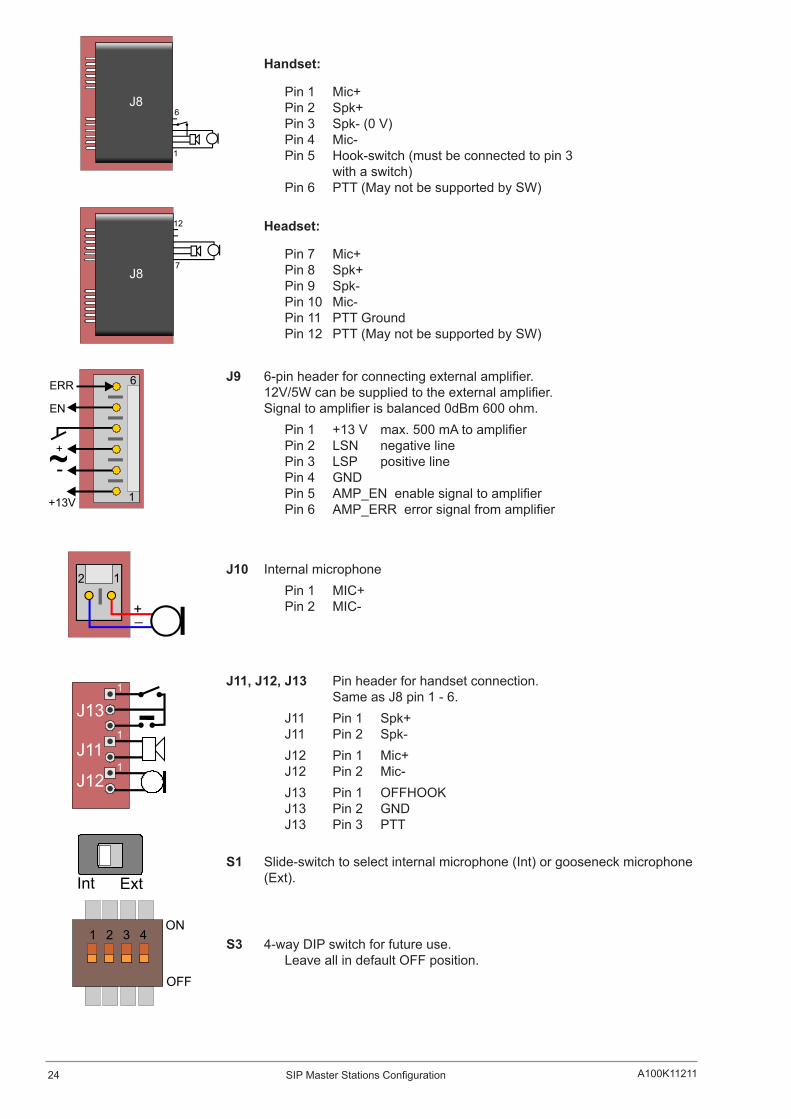
Handset:
Pin 1 Mic+ Pin 2 Spk+ Pin 3 Spk- (0 V) Pin 4 Mic- Pin 5 Hook-switch (must be connected to pin 3 with a switch) Pin 6 PTT (May not be supported by SW)
Headset:
Pin 7 Mic+ Pin 8 Spk+ Pin 9 Spk- Pin 10 Mic- Pin 11 PTT Ground Pin 12 PTT (May not be supported by SW)
J9 6-pin header for connecting external amplifier. 12V/5W can be supplied to the external amplifier. Signal to amplifier is balanced 0dBm 600 ohm.
Pin 1 +13 V max. 500 mA to amplifier Pin 2 LSN negative line Pin 3 LSP positive line Pin 4 GND Pin 5 AMP_EN enable signal to amplifier Pin 6 AMP_ERR error signal from amplifier
J10 Internal microphone Pin 1 MIC+
Pin 2 MIC-
J11, J12, J13 Pin header for handset connection. Same as J8 pin 1 - 6.
J11 Pin 1 Spk+ J11 Pin 2 Spk-
J12 Pin 1 Mic+ J12 Pin 2 Mic-
J13 Pin 1 OFFHOOK J13 Pin 2 GND J13 Pin 3 PTT
S1 Slide-switch to select internal microphone (Int) or gooseneck microphone (Ext).
S3 4-way DIP switch for future use. Leave all in default OFF position.
J8
1
6
J87
12
1
6
+13V
-+
EN
ERR
12
+_
J11
J12
J131
1
1
Int Ext
1 2 3 4ON
OFF

25SIP Master Stations ConfigurationA100K11211
5 Station Indication LEDs
5.1 Station LEDLED4 - Red 5mm LED on board rear side, also seen through front plate.
Flashing at 1 second intervals - Station has no connection to the AlphaCom XE exchange.
Possible reasons:
- No connection to Ethernet - Wrong AlphaCom IP address configured - Invalid IP address - No gateway or wrong gateway to the AlphaCom XE exchange
Flashing at 5 second intervals - Station connected but NOT registered in the AlphaCom XE exchange.
Reason:
- Station has not been programmed in AlphaPro - Missing IP Station license in AlphaCom XE exchange
NoflashingPossible reasons:
- Station connected and registered to the AlphaCom XE exchange - Station not powered up (if no other LEDs are active)
5.2 Status LEDLED3 – Bicolor SMD LED on board component side.
Flashing 2 red + 1 green - Station has no connection to the AlphaCom XE exchange.
Flashing 1 red + 2 green - Station connected but NOT registered in the AlphaCom XE exchange.
Flashing 3 green - Station connected and registered in the AlphaCom XE exchange

26 A100K11211SIP Master Stations Configuration
5.3 Power LEDLED6 – Yellow SMD LED on board component side.
Light: 13 V board power OK.
No light: 13 V board power faulty if no other LEDs are lit.
Possible reasons:
- 24 VDC or PoE not connected - Faulty board
5.4 LAN LEDsThese LEDs are on the LAN (P1) and AUX (P2) RJ45 ports.
Left LEDSteady light: Ethernet connection OK
Flashing: Ethernet traffic
No light: No Ethernet connection
Right LEDLight: 100 Mbit Ethernet connection
No light: 10 Mbit Ethernet connection
27SIP Master Stations ConfigurationA100K11211
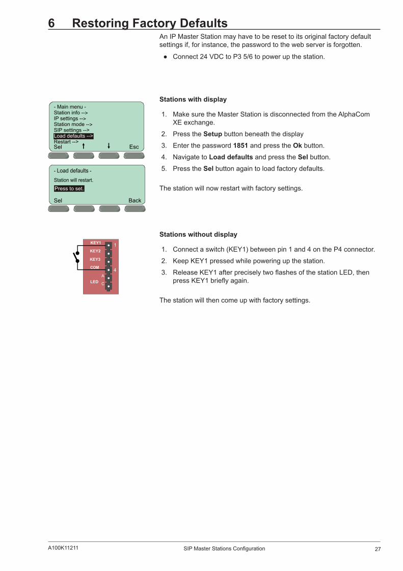
6 Restoring Factory DefaultsAn IP Master Station may have to be reset to its original factory default settings if, for instance, the password to the web server is forgotten.
Connect 24 VDC to P3 5/6 to power up the station.
Stations with display
1. Make sure the Master Station is disconnected from the AlphaCom XE exchange.
2. Press the Setup button beneath the display
3. Enter the password 1851 and press the Ok button.
4. Navigate to Load defaults and press the Sel button.
5. Press the Sel button again to load factory defaults.
The station will now restart with factory settings.
Stations without display
1. Connect a switch (KEY1) between pin 1 and 4 on the P4 connector.
2. Keep KEY1 pressed while powering up the station.
3. Release KEY1 after precisely two flashes of the station LED, then press KEY1 briefly again.
The station will then come up with factory settings.
Sel Esc
- Main menu -Station info -->IP settings -->Station mode -->S
Restart -->
IP settings -->Load defaults -->
BackSel
Press to set.
LED
KEY1
KEY2
KEY3
C
A
1
4
28 A100K11211SIP Master Stations Configuration
7 ConfigurationFileParameters
7.1 Remote Provisioning using TFTP An IP station may be set up to automatically poll configuration from a TFTP server. The IP address of this TFTP server can be obtained using DHCP procedures or be manually configured.
The IP station will first try to download the global configuration file: ipst_config.cfg
Then the IP station will download a device specific configuration file: ipst_config_01_02_03_04_05_06.cfg
where 01_02_03_04_05_06 is the MAC address of the IP station.
If the same parameter is found in both files, the value from the device specific file takes precedence.
7.2 General Parameters
auto_update_interval
Required: No. If this parameter is not set in the file, the function will be disabled.
Description: This parameter enables the station to automatically look for software updates on the TFTP server.
Values: Number of minutes to wait between each server request. Value must be between 1 and 999.
auto_update_image_type
Required: If auto_update_interval is set.
Description: The name of the software image file to be uploaded.
Values: Text giving the name of the software image file. The full name of the file, including extension, is required. This parameter must be set if the auto update function is enabled.
auto_update_image_crc
Required: If auto_update_interval is set.
Description: The CRC checksum calculated for the software image file specified by the auto_update_image_type parameter. This is used to check the integrity of the software file before updating the station.
Values: Hexadecimal value.
29SIP Master Stations ConfigurationA100K11211
7.3 SIP Parameters
nick_name
Required: No. Defaults to sip_id.
Description: The nickname for the station can be used to assign a logical name to the station. For example, a station belonging to James may be assigned the nickname “James” or “James’ station”.
Values: Text string. Max length is 64 characters.
sip_id
Required: Yes
Description: This is the identification of the station in the SIP domain, i.e. the phone number of the station.
Values: Integer value. Max length is 64 characters.
sip_domain
Required: Yes
Description: SIP domain is a server that uses SIP (Session Initiation Protocol) to manage real-time communication among SIP clients. The sip_domain parameter specifies the primary domain for the station, as opposed to sip_domain2 which specifies the secondary (or fallback) domain. The IP address for the SIP domain server (e.g. Asterisk or Cisco Call Manager) should be defined in this section.
Values: IP address given in regular dot notation, e.g. 10.5.2.100
sip_domain2
Required: No
Description: This is the secondary (or fallback) domain. If the station loses connection to the primary SIP domain, it will switch over to the secondary domain.
Values: IP address given in regular dot notation, e.g. 10.5.2.100
auth_user
Required: Only if the SIP server requires authentication.
Description: The authentication user name used to register the station to the SIP server.
Values: Text string.
auth_pwd
Required: Only if the SIP server requires authentication.
Description: The authentication user password used to register the station to the SIP server.
Values: Text string.
sip_outbound_proxy
Required: Optional
Description: Configures an outbound proxy server that receives all initiating request (INVITE and SUBSCRIBE) messages.
Values: IP address given in regular dot notation, e.g. 10.5.2.100
30 A100K11211SIP Master Stations Configuration
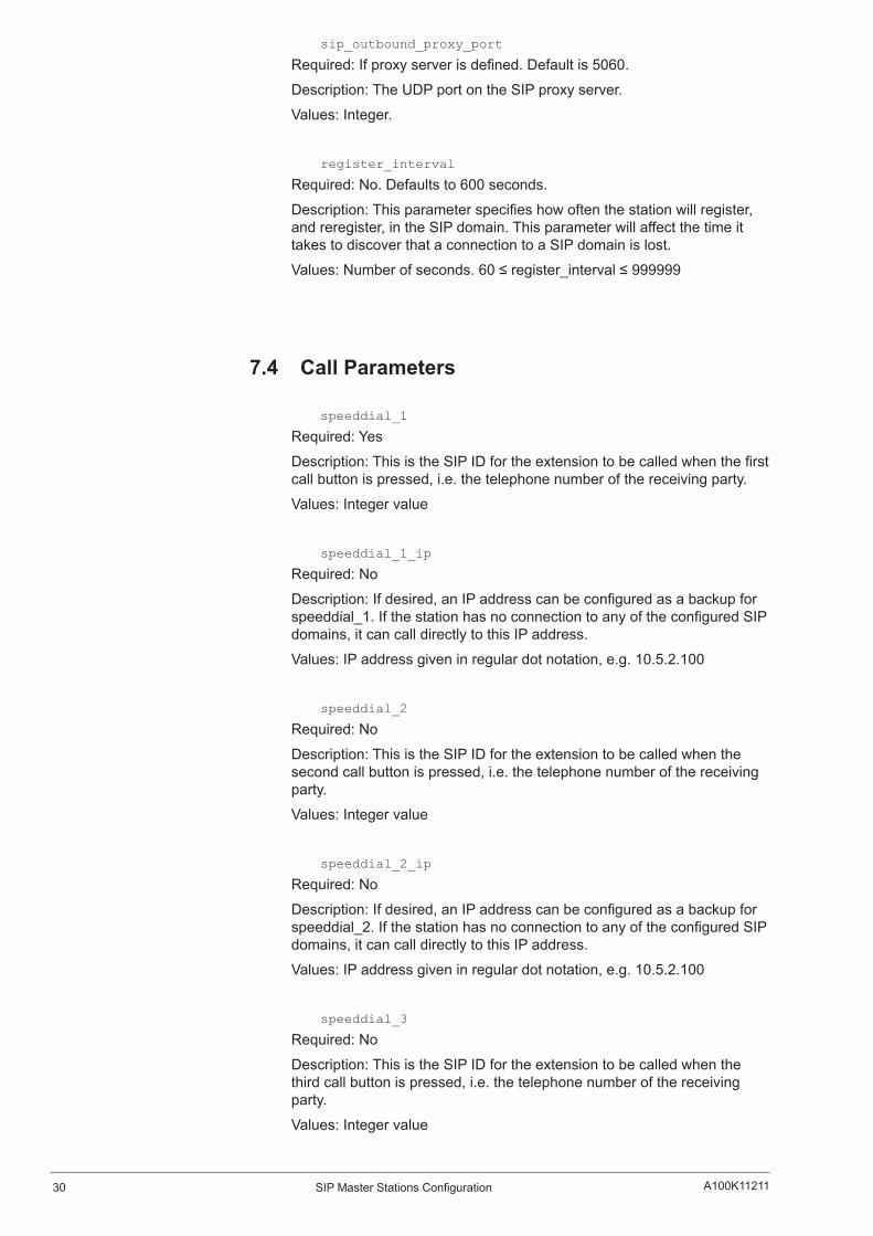
sip_outbound_proxy_port
Required: If proxy server is defined. Default is 5060.
Description: The UDP port on the SIP proxy server.
Values: Integer.
register_interval
Required: No. Defaults to 600 seconds.
Description: This parameter specifies how often the station will register, and reregister, in the SIP domain. This parameter will affect the time it takes to discover that a connection to a SIP domain is lost.
Values: Number of seconds. 60 ≤ register_interval ≤ 999999
7.4 Call Parameters
speeddial_1
Required: Yes
Description: This is the SIP ID for the extension to be called when the first call button is pressed, i.e. the telephone number of the receiving party.
Values: Integer value
speeddial_1_ip
Required: No
Description: If desired, an IP address can be configured as a backup for speeddial_1. If the station has no connection to any of the configured SIP domains, it can call directly to this IP address.
Values: IP address given in regular dot notation, e.g. 10.5.2.100
speeddial_2
Required: No
Description: This is the SIP ID for the extension to be called when the second call button is pressed, i.e. the telephone number of the receiving party.
Values: Integer value
speeddial_2_ip
Required: No
Description: If desired, an IP address can be configured as a backup for speeddial_2. If the station has no connection to any of the configured SIP domains, it can call directly to this IP address.
Values: IP address given in regular dot notation, e.g. 10.5.2.100
speeddial_3
Required: No
Description: This is the SIP ID for the extension to be called when the third call button is pressed, i.e. the telephone number of the receiving party.
Values: Integer value
31SIP Master Stations ConfigurationA100K11211
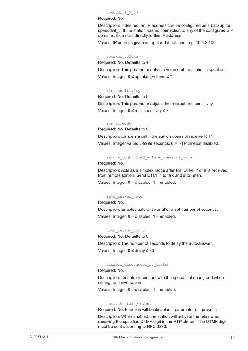
speeddial_3_ip
Required: No
Description: If desired, an IP address can be configured as a backup for speeddial_3. If the station has no connection to any of the configured SIP domains, it can call directly to this IP address.
Values: IP address given in regular dot notation, e.g. 10.5.2.100
speaker_volume
Required: No. Defaults to 4.
Description: This parameter sets the volume of the station’s speaker.
Values: Integer. 0 ≤ speaker_volume ≤ 7
mic_sensitivity
Required: No. Defaults to 5.
Description: This parameter adjusts the microphone sensitivity.
Values: Integer. 0 ≤ mic_sensitivity ≤ 7
rtp_timeout
Required: No. Defaults to 0.
Description: Cancels a call if the station does not receive RTP.
Values: Integer value: 0-9999 seconds. 0 = RTP timeout disabled.
remote_controlled_volume_override_mode
Required: No.
Description: Acts as a simplex mode after first DTMF * or # is received from remote station. Send DTMF * to talk and # to listen.
Values: Integer. 0 = disabled, 1 = enabled.
auto_answer_mode
Required: No.
Description: Enables auto-answer after a set number of seconds.
Values: Integer. 0 = disabled, 1 = enabled.
auto_answer_delay
Required: No. Defaults to 0.
Description: The number of seconds to delay the auto-answer.
Values: Integer. 0 ≤ delay ≤ 30
disable_disconnect_by_button
Required: No.
Description: Disable disconnect with the speed dial during and when setting up conversation.
Values: Integer. 0 = disabled, 1 = enabled.
activate_relay_event
Required: No. Function will be disabled if parameter not present.
Description: When enabled, the station will activate the relay when receiving the specified DTMF digit in the RTP stream. The DTMF digit must be sent according to RFC 2833.

32 A100K11211SIP Master Stations Configuration
Values: Integer. 0 ≤ activate_relay_event ≤ 9
activate_relay_duration
Required: No. Defaults to 60.
Description: This parameter sets the duration for the relay activation in seconds.
Values: 0 ≤ activate_relay_duration ≤ 240. 0 means that the relay stays open.
7.5 SNMP Parameters
trap_receiver
Required: No.
Description: The IP address of the server receiving SNMP traps.
Values: IP address given in regular dot notation, e.g. 10.5.2.100
network
Required: No.
Description: Used, together with the network mask, to determine the allowed network for reading the MIB on the IP station.
Values: IP address given in regular dot notation, e.g. 10.5.2.100. For example, with an allowed network of 10.5.2.0 and a network mask of 24, anyone with IP address 10.5.2.0 to 10.5.2.255 can access the MIB.
network_mask
Required: No.
Description: The mask used to determine the allowed network for reading the MIB.
Values: Integer. 0 ≤ network_mask ≤ 32. For example, with an allowed network of 10.5.2.0 and a network mask of 24, anyone with IP address 10.5.2.0 to 10.5.2.255 can access the MIB.
community
Required: No.
Description: A text string used as a password for authentication.
Values: String.
enable_v1
Required: No.
Description: Enables reading of MIB using SNMP version 1.
Values: Integer. 1 = enabled, 0 = disabled.
enable_v2c
Required: No.
Description: Enables reading of MIB using SNMP version 2c.
Values: Integer. 1 = enabled, 0 = disabled.
33SIP Master Stations ConfigurationA100K11211
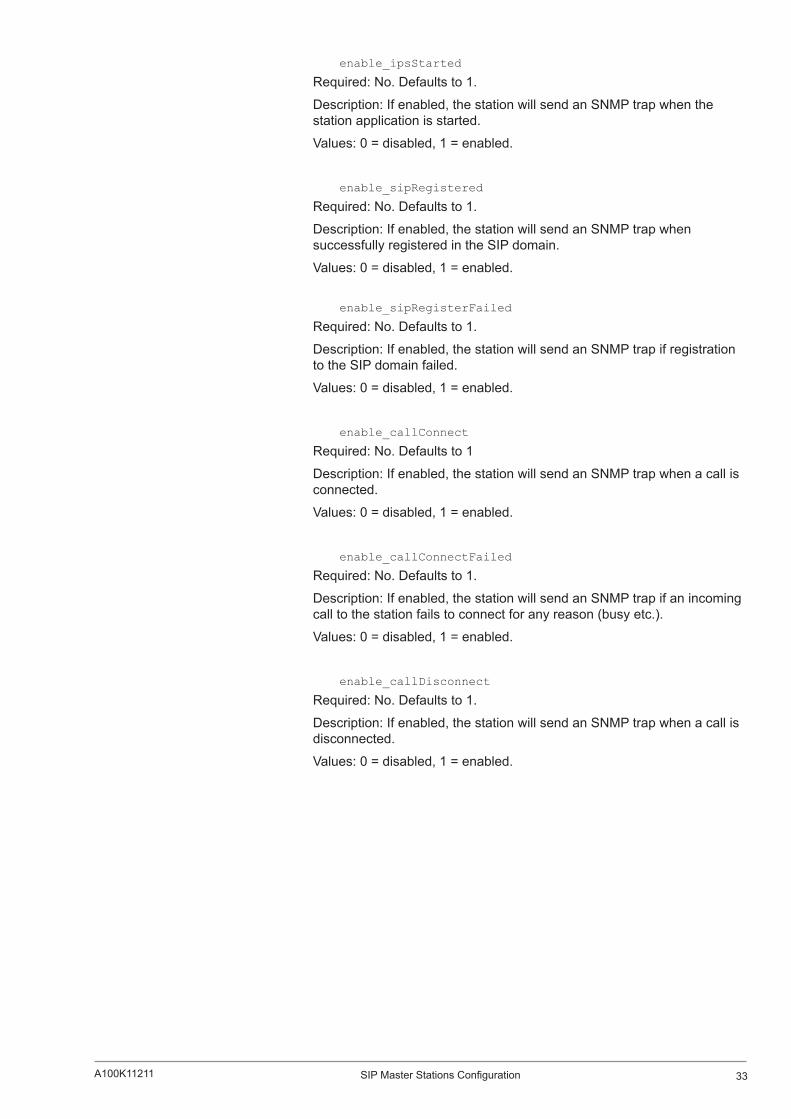
enable_ipsStarted
Required: No. Defaults to 1.
Description: If enabled, the station will send an SNMP trap when the station application is started.
Values: 0 = disabled, 1 = enabled.
enable_sipRegistered
Required: No. Defaults to 1.
Description: If enabled, the station will send an SNMP trap when successfully registered in the SIP domain.
Values: 0 = disabled, 1 = enabled.
enable_sipRegisterFailed
Required: No. Defaults to 1.
Description: If enabled, the station will send an SNMP trap if registration to the SIP domain failed.
Values: 0 = disabled, 1 = enabled.
enable_callConnect
Required: No. Defaults to 1
Description: If enabled, the station will send an SNMP trap when a call is connected.
Values: 0 = disabled, 1 = enabled.
enable_callConnectFailed
Required: No. Defaults to 1.
Description: If enabled, the station will send an SNMP trap if an incoming call to the station fails to connect for any reason (busy etc.).
Values: 0 = disabled, 1 = enabled.
enable_callDisconnect
Required: No. Defaults to 1.
Description: If enabled, the station will send an SNMP trap when a call is disconnected.
Values: 0 = disabled, 1 = enabled.
34 A100K11211SIP Master Stations Configuration
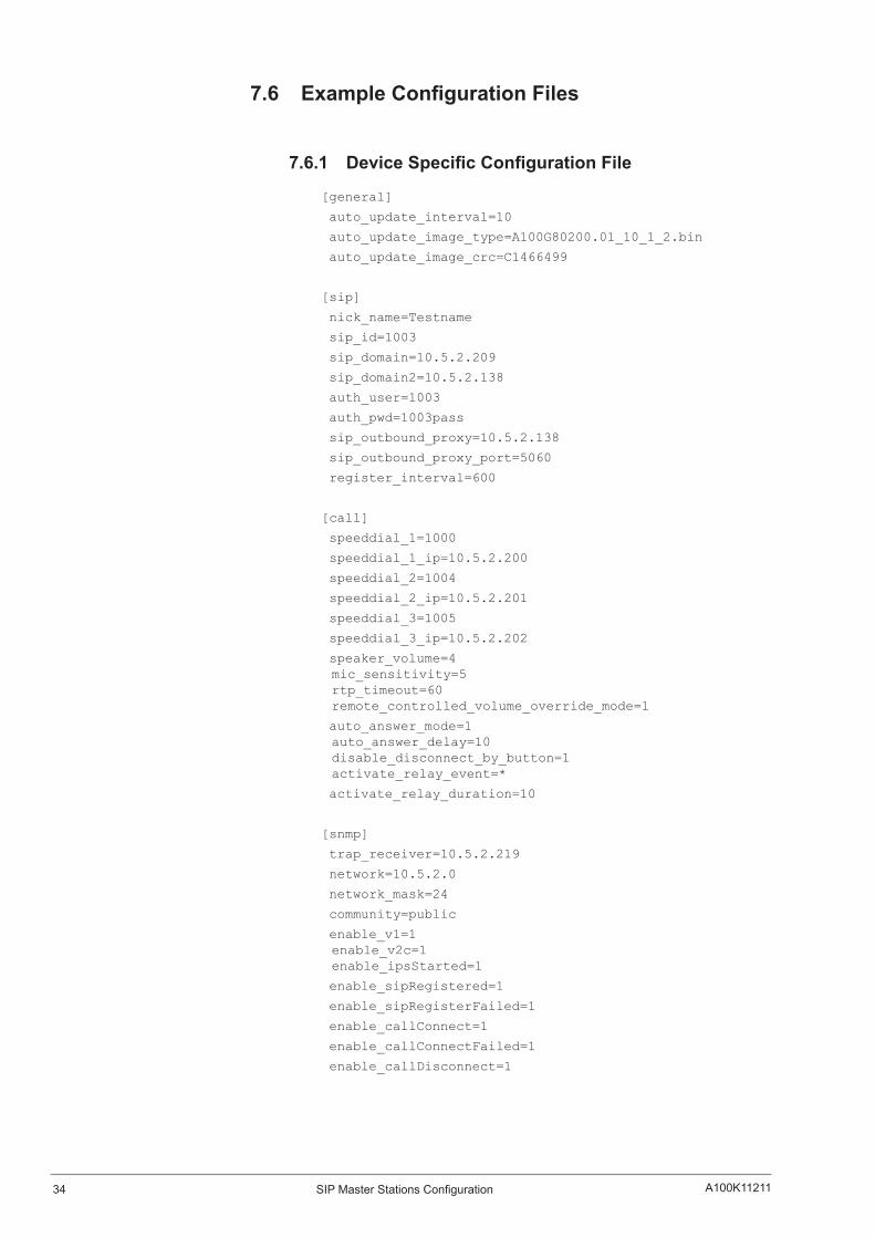
7.6 ExampleConfigurationFiles
7.6.1 DeviceSpecificConfigurationFile
[general]
auto_update_interval=10
auto_update_image_type=A100G80200.01_10_1_2.bin
auto_update_image_crc=C1466499
[sip]
nick_name=Testname
sip_id=1003
sip_domain=10.5.2.209
sip_domain2=10.5.2.138
auth_user=1003
auth_pwd=1003pass
sip_outbound_proxy=10.5.2.138
sip_outbound_proxy_port=5060
register_interval=600
[call]
speeddial_1=1000
speeddial_1_ip=10.5.2.200
speeddial_2=1004
speeddial_2_ip=10.5.2.201
speeddial_3=1005
speeddial_3_ip=10.5.2.202
speaker_volume=4 mic_sensitivity=5 rtp_timeout=60 remote_controlled_volume_override_mode=1
auto_answer_mode=1 auto_answer_delay=10 disable_disconnect_by_button=1 activate_relay_event=*
activate_relay_duration=10
[snmp]
trap_receiver=10.5.2.219
network=10.5.2.0
network_mask=24
community=public
enable_v1=1 enable_v2c=1 enable_ipsStarted=1
enable_sipRegistered=1
enable_sipRegisterFailed=1
enable_callConnect=1
enable_callConnectFailed=1
enable_callDisconnect=1

35SIP Master Stations ConfigurationA100K11211
7.6.2 GlobalConfigurationFile
The global configuration file has the same parameters as the device specific file except that the four parameters below will be ignored. Hence, it is recommended that the following parameters not be used in the global configuration file.
nick_name
sip_id
auth_user
auth_pwd

www.stentofon.com Zenitel Norway ASP.O. Box 4498 NydalenNO-0403 OSLONorway
STENTOFON and VINGTOR products are developed and marketed by Zenitel Norway AS. The company’s Quality Assurance System is certified to meet the requirements in NS-EN ISO 9001:2008. Zenitel Norway AS reserves the right to modify designs and alter specifications without prior notice in pursuance of a policy of continuous improvement. ©2012 Zenitel Norway AS.