Embed Size (px)
Citation preview
DCN 9209-31000-00sPro 60 SLS Center
Sinterstation® sPro™ 60 SLS® CenterSite Preparation Guide (Preliminary)

sPro 60 SLS Center Site Preparation Guide
How to Prepare for Installation . . . . . . . . . . . . . . . . . . . . . . . . . . . . . . .1Before Scheduling Installation1
When You are Ready for Installation2
What Your System Includes . . . . . . . . . . . . . . . . . . . . . . . . . . . . . . . . . .3Required System Components4
Recommended Optional Equipment12
Consumables15
Facility Information Form . . . . . . . . . . . . . . . . . . . . . . . . . . . . . . . . . .19How 3D Systems Uses Facility Information19
Facility Information Form Instructions20
sPro 60 SLS Systems Facility Information Form21
Facility Requirements Checklist. . . . . . . . . . . . . . . . . . . . . . . . . . . . . .23About the Checklist23
How to Submit Your Completed Facilities Checklist24
Facility Requirements Checklist25
Room Requirements . . . . . . . . . . . . . . . . . . . . . . . . . . . . . . . . . . . . . . .27Clearance Requirements27
Floor Requirements27
Atmosphere Requirements . . . . . . . . . . . . . . . . . . . . . . . . . . . . . . . . . .29Electrical Requirements . . . . . . . . . . . . . . . . . . . . . . . . . . . . . . . . . . . .31
Process Station Power Requirements31
sPro 60 SLS Center Transformer Requirements32
Grounding Requirements34
Chiller Requirements. . . . . . . . . . . . . . . . . . . . . . . . . . . . . . . . . . . . . . .35Chiller Electrical Requirements35
Chiller Coolant Requirements35
Third Party Chiller Requirements36
Nitrogen Requirements . . . . . . . . . . . . . . . . . . . . . . . . . . . . . . . . . . . . .37Nitrogen Supply Requirements37
Nitrogen Supply Options38
Nitrogen Supply and Exhaust Lines41
Receiving and Moving the System . . . . . . . . . . . . . . . . . . . . . . . . . . . .43What Your Shipment Includes44
SLS Materials and Filters46
Shipping Weights and Dimensions47
June 2009 DCN 9209-31000-00 i
sPro 60 SLS Center Site Preparation Guide
System Component Weights and Dimensions50
Moving the sPro 60 SLS Center52
Installation Verifications (performed by 3D Systems)54
Part Finishing Area Facilities Requirements. . . . . . . . . . . . . . . . . . . 55Part Finishing and Maintenance Equipment List55
Electrical Requirements for Part Finishing Equipment56
Part Finishing Equipment Dimensions and Weights56
Safety . . . . . . . . . . . . . . . . . . . . . . . . . . . . . . . . . . . . . . . . . . . . . . . . . . . 67General Operator Safety Information67
Laser Safety70
3D Systems Laser Service Procedures71
Powder Safety72
Powder Storage73
Electrical Safety74
Nitrogen/Oxygen Safety74
Optional Safety Equipment75
Contacting 3D Systems . . . . . . . . . . . . . . . . . . . . . . . . . . . . . . . . . . . . 79For Customer Support79
About this Manual79
Legal Notices . . . . . . . . . . . . . . . . . . . . . . . . . . . . . . . . . . . . . . . . . . . . . 80
ii DCN 9209-31000-00 3D Systems Corporation
How to Prepare for InstallationUse this guide to prepare your facility for the installation of:
3D Systems Corporation’s sPro 60 SLS Center.Auxiliary equipment for finishing parts made with 3D Systems’ Selective Laser Sintering (SLS) process
Also refer to the sPro 60 SLS Center Facility Requirements drawing (DCN 8001-20020) as you work through the requirements.
Before Scheduling InstallationBefore 3D Systems Field Service can install the sPro 60 at your site, you must do the following:
Complete the facility requirements listed in each “Requirements” section of this guide.
Complete and submit the “Facility Information Form” (page 19) and the “Facility Requirements Checklist” (page 23) to 3D Systems Customer Support via fax, mail, or e-mail.
The “Facility Requirements Checklist” must be completed before 3D Systems Field Service can install the sPro 60 at your site.
NOTE If you plan to use 3D Systems’ LaserForm ST-100 metal material, you must also complete and submit the “Facility Requirements Checklist” for the LaserForm Oven found in the “Facility Requirements” section of the LaserForm Oven Guide (DCN 8002-20031).
June 2009 DCN 9209-31000-00 1

How to Prepare for Installation sPro 60 SLS Center Site Preparation Guide
When You are Ready for InstallationOnce your facility is ready and you’ve scheduled an installation date with 3D Systems Customer Support, read “Receiving and Moving the System” starting on page 43. This will show you how to properly unpack the sPro 60 system and move it into place.
Also, before using the sPro 60, please read the “Safety” chapter starting on page 67 to find out the how to safely handle the SLS materials and various system components.
2 DCN 9209-31000-00 3D Systems Corporation
What Your System IncludesThis section lists all required and optional components of a 3D Systems sPro 60 SLS Center. These include:
An sPro 60 process station for building the SLS parts Equipment for breaking out and finishing SLS partsMaintenance and safety equipment for cleaning the process station and protecting operators and service personnelItems consumed during part builds (“consumables”) such as powder, nitrogen, and filters
NOTE The sPro 60 SLS Center builds many types of parts out of several types of SLS materials. Each application has some unique requirements. Your system will, most likely, not include every component and material listed in this section. Just focus on the components and materials included in your order.
It is especially important that you prepare your facilities for all non-3D Systems-supplied components in your order. These are listed as “customer-supplied and installed” in this section. The facilities for these non-3D Systems-supplied components—and in some cases the components themselves—must be in place before the sPro 60 SLS Center can be installed.
June 2009 DCN 9209-31000-00 3
What Your System Includes sPro 60 SLS Center Site Preparation Guide
Required System ComponentsYour sPro 60 SLS Center must include the components described below. Most of these components are 3D Systems-supplied and installed; others can be one of the following:
Customer supplied and supplier-installed, or, Customer supplied and 3D Systems-installed
When a required system component can be customer-supplied, the source (or sources) for the component are listed, along with purchasing information.1
All required system components are listed below. Each component is detailed separately in the sections that follow.
Process Station (page 5)Chiller (page 6)Nitrogen Supply (page 7)Breakout Station (BOS) (page 8)Non-ignition Vacuum Cleaner (page 9)Laser Safety Curtains or Partitions (page 9)LaserForm Oven (page 10)SandForm/CastForm Forced Convection Oven (page 10)sPro 60 SLS Center Transformer (page 11)
1. Purchasing information is current at the time of printing, however, it is subject to change. Contact 3D Systems Customer Support if you need help contacting a supplier.
4 DCN 9209-31000-00 3D Systems Corporation
sPro 60 SLS Center Site Preparation Guide What Your System Includes
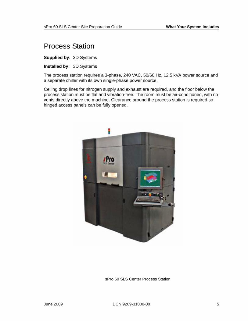
Process StationSupplied by: 3D Systems
Installed by: 3D Systems
The process station requires a 3-phase, 240 VAC, 50/60 Hz, 12.5 kVA power source and a separate chiller with its own single-phase power source.
Ceiling drop lines for nitrogen supply and exhaust are required, and the floor below the process station must be flat and vibration-free. The room must be air-conditioned, with no vents directly above the machine. Clearance around the process station is required so hinged access panels can be fully opened.
sPro 60 SLS Center Process Station
June 2009 DCN 9209-31000-00 5
What Your System Includes sPro 60 SLS Center Site Preparation Guide
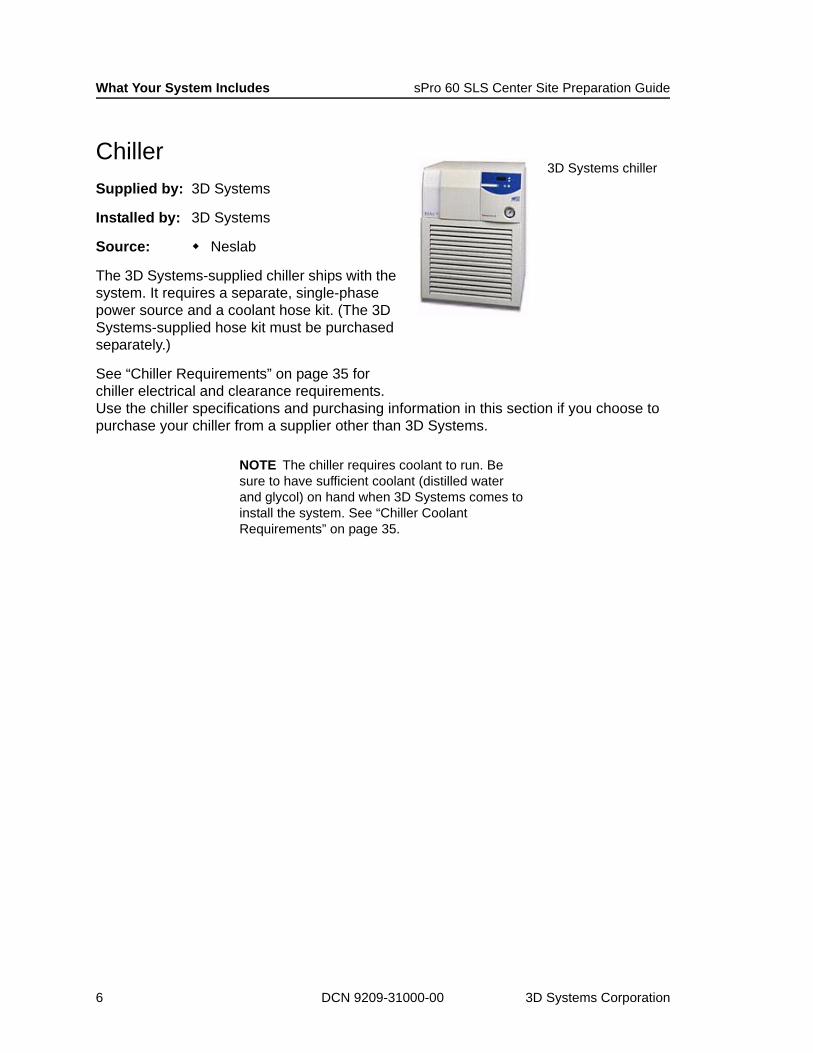
ChillerSupplied by: 3D Systems
Installed by: 3D Systems
Source: Neslab
The 3D Systems-supplied chiller ships with the system. It requires a separate, single-phase power source and a coolant hose kit. (The 3D Systems-supplied hose kit must be purchased separately.)
See “Chiller Requirements” on page 35 for chiller electrical and clearance requirements. Use the chiller specifications and purchasing information in this section if you choose to purchase your chiller from a supplier other than 3D Systems.
NOTE The chiller requires coolant to run. Be sure to have sufficient coolant (distilled water and glycol) on hand when 3D Systems comes to install the system. See “Chiller Coolant Requirements” on page 35.
3D Systems chiller
6 DCN 9209-31000-00 3D Systems Corporation

sPro 60 SLS Center Site Preparation Guide What Your System Includes
Nitrogen SupplySupplied by: Customer
Installed by: Customer (prior to sPro 60 SLS Center installation)
Source: Local nitrogen supplier
The nitrogen supply can be any one of the following:
Two or more nitrogen dewars connected with an auto-switching manifold (as shown)Bulk nitrogen tank (as shown)A nitrogen generator with or without a compressor and surge tank
The nitrogen supply you choose depends on your projected consumption and the materials you plan to run. If you choose to use a nitrogen generator, you must decide whether or not you will need a compressor and surge tank.
NOTE If a LaserForm Oven will share the nitrogen supply, you must use liquid or bottled nitrogen. The nitrogen generator does not produce sufficiently pure nitrogen for the oven.
NOTE 3D Systems does not install, service, or support nitrogen generators.
See “Nitrogen Requirements” on page 37 for nitrogen supply equipment specifications and purchasing information.
Nitrogen dewars for low-to-medium volume operations
Bulk nitrogen tank for high volume operations
Facility nitrogen supply examples
June 2009 DCN 9209-31000-00 7
What Your System Includes sPro 60 SLS Center Site Preparation Guide
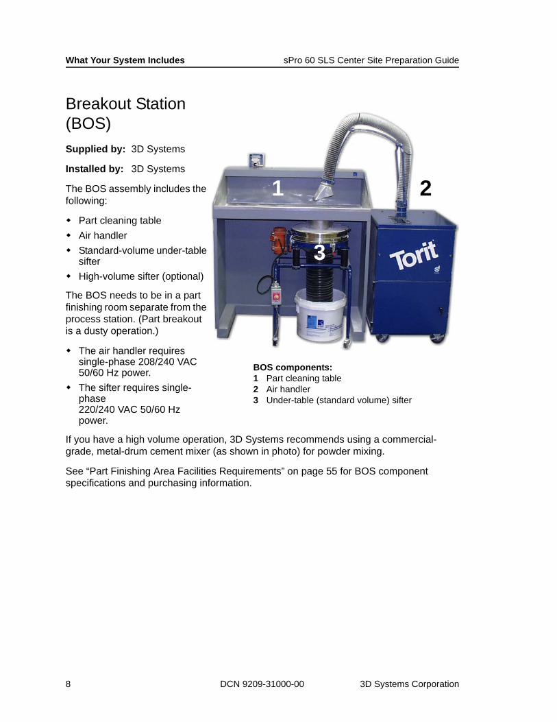
Breakout Station (BOS)Supplied by: 3D Systems
Installed by: 3D Systems
The BOS assembly includes the following:
Part cleaning tableAir handlerStandard-volume under-table sifterHigh-volume sifter (optional)
The BOS needs to be in a part finishing room separate from the process station. (Part breakout is a dusty operation.)
The air handler requires single-phase 208/240 VAC 50/60 Hz power.The sifter requires single-phase 220/240 VAC 50/60 Hz power.
If you have a high volume operation, 3D Systems recommends using a commercial-grade, metal-drum cement mixer (as shown in photo) for powder mixing.
See “Part Finishing Area Facilities Requirements” on page 55 for BOS component specifications and purchasing information.
1 2
3
BOS components: 1 Part cleaning table2 Air handler3 Under-table (standard volume) sifter
8 DCN 9209-31000-00 3D Systems Corporation

sPro 60 SLS Center Site Preparation Guide What Your System Includes
Non-ignition Vacuum CleanerSupplied by: 3D Systems or customer
Installed by: Supplier (3D Systems or customer)
Source: American Vacuum Company (U.S. and Asia Pacific)Nilfisk Advance AG (Europe)
The vacuum is used to clean the process station between builds. A “non-ignition” model is required due to the potential combustibility of airborne powder.
See “Optional Safety Equipment” on page 83 for vacuum safety guidelines, specifications, and purchasing information.
Laser Safety Curtains or PartitionsSupplied by: Customer
Installed by: Customer
Source: KENTEK Corporation
Laser safety curtains or partitions are required if the sPro 60 SLS Center room cannot be secured during laser calibration.
NOTE Laser safety curtains or partitions must be in place before 3D Systems performs laser maintenance.
See “Optional Safety Equipment” on page 83 for further details.
Non-ignition vacuum cleaner
Example laser safety curtains and partitions
June 2009 DCN 9209-31000-00 9
What Your System Includes sPro 60 SLS Center Site Preparation Guide
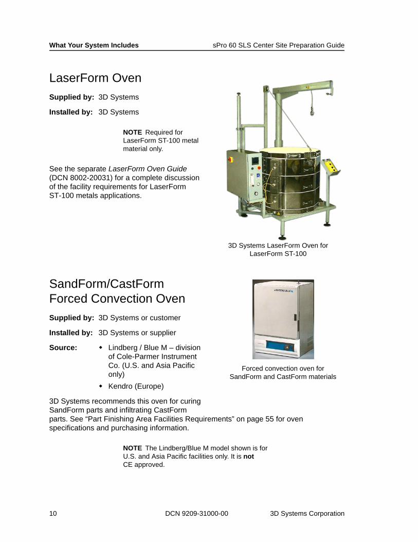
LaserForm OvenSupplied by: 3D Systems
Installed by: 3D Systems
NOTE Required for LaserForm ST-100 metal material only.
See the separate LaserForm Oven Guide (DCN 8002-20031) for a complete discussion of the facility requirements for LaserForm ST-100 metals applications.
SandForm/CastForm Forced Convection OvenSupplied by: 3D Systems or customer
Installed by: 3D Systems or supplier
Source: Lindberg / Blue M – division of Cole-Parmer Instrument Co. (U.S. and Asia Pacific only)Kendro (Europe)
3D Systems recommends this oven for curing SandForm parts and infiltrating CastForm parts. See “Part Finishing Area Facilities Requirements” on page 55 for oven specifications and purchasing information.
NOTE The Lindberg/Blue M model shown is for U.S. and Asia Pacific facilities only. It is not CE approved.
3D Systems LaserForm Oven forLaserForm ST-100
Forced convection oven for SandForm and CastForm materials
10 DCN 9209-31000-00 3D Systems Corporation
sPro 60 SLS Center Site Preparation Guide What Your System Includes
sPro 60 SLS Center TransformerSupplied by: 3D Systems or customer
Installed by: Supplier (prior to sPro 60 SLS Center installation)
Source: Nova Magnetics (recommended; U.S. and Asia Pacific)Isoltra Transformatorenbau GmBH (recommended; Europe)
A customer-supplied step-up or step-down transformer is required if the facility does not have 240 VAC, 3-phase, 50/60 Hz, 12.5 kVA power. A CE-approved version of the transformer is available for European installations through 3D Systems-Europe.
See “Electrical Requirements” on page 31 for descriptions of each of the four types of transformers 3D Systems stocks.
NOTE The LaserForm Oven might also require a transformer if facility power does not match its power requirements. See the “Facility Requirements” section of the separate LaserForm Oven Guide (DCN 8002-20031) for further information.
June 2009 DCN 9209-31000-00 11
What Your System Includes sPro 60 SLS Center Site Preparation Guide
Recommended Optional EquipmentYour sPro 60 SLS Center can optionally include the components listed below. These are described in the sections that follow.
Room Area Oxygen Monitor (page 12)Bead Blaster (page 13)Powder Mixer (page 14)1.5 m (5 ft) platform ladder (page 14)Storage cabinet (page 14)Anti-static floor mats (page 14)
All the items above are customer-supplied and installed except for the Bead Blaster, which 3D Systems supplies and installs. 3D Systems can also assist your oxygen monitor supplier with installation.
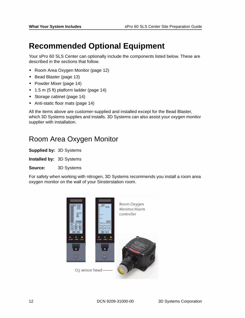
Room Area Oxygen MonitorSupplied by: 3D Systems
Installed by: 3D Systems
Source: 3D Systems
For safety when working with nitrogen, 3D Systems recommends you install a room area oxygen monitor on the wall of your Sinsterstation room.
12 DCN 9209-31000-00 3D Systems Corporation
sPro 60 SLS Center Site Preparation Guide What Your System Includes
See “Nitrogen/Oxygen Safety” on page 74 and “Optional Safety Equipment” on page 83 for more oxygen monitor information.
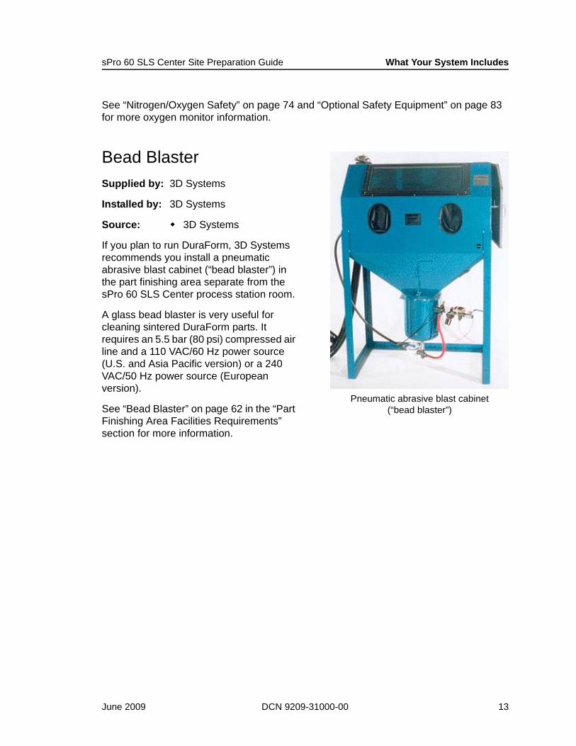
Bead BlasterSupplied by: 3D Systems
Installed by: 3D Systems
Source: 3D Systems
If you plan to run DuraForm, 3D Systems recommends you install a pneumatic abrasive blast cabinet (“bead blaster”) in the part finishing area separate from the sPro 60 SLS Center process station room.
A glass bead blaster is very useful for cleaning sintered DuraForm parts. It requires an 5.5 bar (80 psi) compressed air line and a 110 VAC/60 Hz power source (U.S. and Asia Pacific version) or a 240VAC/50 Hz power source (European version).
See “Bead Blaster” on page 62 in the “Part Finishing Area Facilities Requirements” section for more information.
Pneumatic abrasive blast cabinet(“bead blaster”)
June 2009 DCN 9209-31000-00 13

What Your System Includes sPro 60 SLS Center Site Preparation Guide
Powder MixerSupplied by: Customer
Source: Imer Inc. (www.imerusa.com)
The powder mixer is a standard, low-capacity cement mixer for blending virgin and recycled powder. A drum lid is required to keep powder in the drum while mixing.
The recommended model’s specifications are as follows:
Miscellaneous Service and Maintenance EquipmentSupplied by: Customer
Source: Local hardware store or home center
You should also have the following equipment on site prior to sPro 60 SLS Center installation to facilitate service and maintenance:
1.5 m (5 ft) platform ladder – for installation and serviceStorage cabinet – for maintenance partsAnti-static floor mats – to protect process station and BOS from damaging static discharge
Capacity 0.14 m3 (5 ft3)Motor 0.5 hp
Facility Power 110 VAC, single phase, 60 Hz, 3.0 A, 0.37 kW
Overall Dimensions (W x H x D)
76 cm x 145 cm x 127 cm(30 in x 57 in x 50 in)
Drum Capacity 125 kg (275 lb)Weight 66 kg (145 lb)
CAUTION!
The mixer drum must be metal. Mixing plastic powder in a plastic drum builds up static charge which can lead to damaging electrostatic discharge.
Powder mixer with metal drum
1.5 m (5 ft) platform ladder for service access
14 DCN 9209-31000-00 3D Systems Corporation
sPro 60 SLS Center Site Preparation Guide What Your System Includes
ConsumablesThe following items are consumed at varying rates during the SLS process:
NitrogenSLS Materials (powders, waxes, sprays, etc.)FiltersCoolant
These items are described separately in the sections that follow.
Contact 3D Systems to purchase replacement SLS materials and filters. See your nitrogen and coolant supplier to replenish stocks of these items.
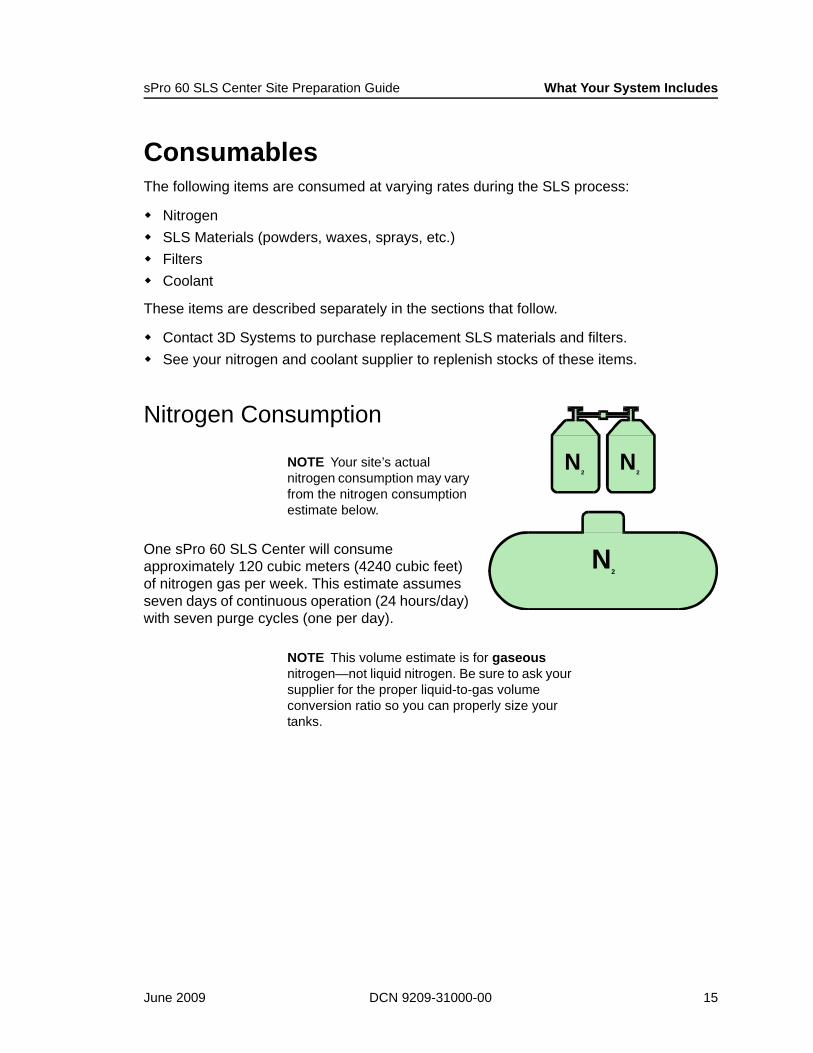
Nitrogen Consumption
NOTE Your site’s actual nitrogen consumption may vary from the nitrogen consumption estimate below.
One sPro 60 SLS Center will consume approximately 120 cubic meters (4240 cubic feet) of nitrogen gas per week. This estimate assumes seven days of continuous operation (24 hours/day) with seven purge cycles (one per day).
NOTE This volume estimate is for gaseous nitrogen—not liquid nitrogen. Be sure to ask your supplier for the proper liquid-to-gas volume conversion ratio so you can properly size your tanks.
N2
N2
N2
June 2009 DCN 9209-31000-00 15
What Your System Includes sPro 60 SLS Center Site Preparation Guide
SLS MaterialsThe SLS process consumes SLS materials when making parts. The materials listed below are available for purchase from 3D Systems. Each comes with its own 3D Systems Material Guide to help you use it successfully.
DuraForm™ PADuraForm™ GFDuraForm™ FlexDuraForm™ AFDuraForm™ EX BlackDuraForm™ EX NaturalDuraForm™ HS-10 General PurposeDuraForm™ HS-10 StiffBronze InfiltrantAlumina PowderCastForm™ PSLaserForm ST-100™LaserForm A6
See “Electrical Safety” on page 74 to help you determine your SLS material storage needs.
16 DCN 9209-31000-00 3D Systems Corporation

sPro 60 SLS Center Site Preparation Guide What Your System Includes
Replaceable FiltersThe process station and chiller have customer-replaceable filters. 3D Systems recommends you keep a supply of these filters on hand and replace them when necessary to ensure part quality and trouble-free operation.
These filters include:
Process chamber filter (particulate)Process chamber duct filter (charcoal)Nitrogen system exhaust filter (cellulose)IR block coolant filterChiller air filter (if chiller is purchased from 3D Systems)Chiller coolant filter (if chiller is purchased from 3D Systems)
See the sPro 60 SLS Centers Reference Guide (DCN 8002-00002) for filter replacement information.
NOTE Filters are also replaced as necessary by your 3D Systems Field Service Representative during scheduled preventive maintenance visits.
Process chamber duct filter at rear of process station
June 2009 DCN 9209-31000-00 17
What Your System Includes sPro 60 SLS Center Site Preparation Guide
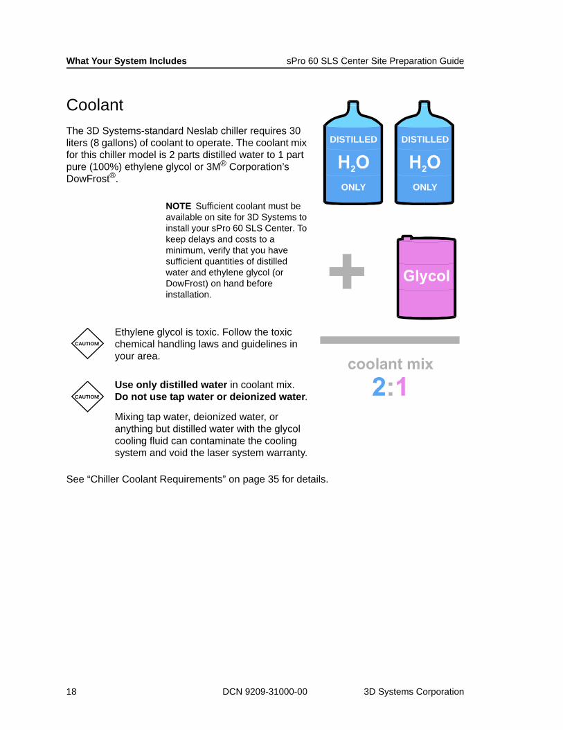
CoolantThe 3D Systems-standard Neslab chiller requires 30 liters (8 gallons) of coolant to operate. The coolant mix for this chiller model is 2 parts distilled water to 1 part pure (100%) ethylene glycol or 3M® Corporation’s DowFrost®.
NOTE Sufficient coolant must be available on site for 3D Systems to install your sPro 60 SLS Center. To keep delays and costs to a minimum, verify that you have sufficient quantities of distilled water and ethylene glycol (or DowFrost) on hand before installation.
See “Chiller Coolant Requirements” on page 35 for details.
CAUTION!
Ethylene glycol is toxic. Follow the toxic chemical handling laws and guidelines in your area.
CAUTION!
Use only distilled water in coolant mix. Do not use tap water or deionized water.
Mixing tap water, deionized water, or anything but distilled water with the glycol cooling fluid can contaminate the cooling system and void the laser system warranty.
DISTILLED DISTILLED
ONLY ONLY
18 DCN 9209-31000-00 3D Systems Corporation

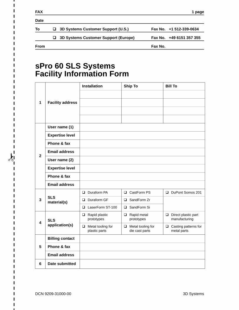
Facility Information FormAs soon as you receive this guide, complete the “sPro 60 SLS Systems Facility Information Form” on page 21.
Fax your completed form to 3D Systems Customer Support at one of the following numbers:
+1 512 339-0634 (North & South America; Asia Pacific)
+49 6151 357 355 (Europe)
3D Systems must acknowledge receipt of your completed “sPro 60 SLS Systems Facility Information Form” before Customer Support can schedule a trip to your facility to install the sPro 60 SLS System.
How 3D Systems Uses Facility Information3D Systems Customer Support keeps track of machine configurations and maintenance histories in a database. The information in this database is updated based on the content of the “Facility Information Form” you submit.
If you call 3D Systems to schedule maintenance on your machine or get technical assistance, 3D Systems Customer Support uses this database to help you get the results you need. Therefore, it is very important that the information you provide on the “sPro 60 SLS Systems Facility Information Form” is complete and accurate.
NOTE 3D Systems only uses the information you submit to better support and service your machine. 3D Systems does not sell or otherwise disclose private customer information to third parties without permission.
June 2009 DCN 9209-31000-00 19

Facility Information Form sPro 60 SLS Systems Site Preparation Guide
Facility Information Form InstructionsUse these instructions to help you complete and submit the “sPro 60 SLS Systems Facility Information Form” on the next page.
Fax, mail, or email the completed form to one of the 3D Systems Customer Support sites below.
If you want to speak to a 3D Systems Customer Support representative about your facility, call +1-800-999-5553 (U.S.), +49 6151 357 452 (Europe), or +65 430-6681 (Asia Pacific).
Line No. Instructions
1
Enter the installation address of the building where the sPro 60 SLS System(s) will be installed. (If you have a large facility, be specific; for example, include building and room numbers.)Enter the shipping address and billing address if they are different than the installation address.
2
Enter contact information for all persons who will be using and maintaining the sPro 60 SLS System. Specify each user’s level of expertise; e.g., “engineer,” “operator,” “expert,” or “novice.”
3 Check all the materials that you intend to use in your sPro 60 SLS System.
4 Check all the applications that you intend to run on your sPro 60 SLS System.
5 Enter the contact information for the person or persons at your facility responsible for handling accounts payable to 3D Systems.
6Enter the date you submitted this form to 3D Systems Customer Support. If you had to submit this form more than once, enter the most recent submission date.
North & South America; Asia Pacific Europe
Fax +1 512-339-0634attn: SLS Customer Support
+49 6151 357 355attn: SLS Customer Support
3D Systems Corporation333 Three D Systems CircleRock Hill, SC 29730attn: SLS Customer Support
3D Systems GmbHRontgenstrasse 41D-64291 Darmstadt, Germanyattn: SLS Customer Support
Email support@3D Systems3D Systems-corp.com
support@3D Systems3D Systems-corp.com
20 DCN 9209-31000-00 3D Systems Corporation
FAX 1 page
Date
To 3D Systems Customer Support (U.S.) Fax No. +1 512-339-0634
3D Systems Customer Support (Europe) Fax No. +49 6151 357 355
From Fax No.
✁
sPro 60 SLS Systems Facility Information Form
1 Facility address
Installation Ship To Bill To
2
User name (1)
Expertise level
Phone & fax
Email address
User name (2)
Expertise level
Phone & fax
Email address
3 SLS material(s)
Duraform PA CastForm PS DuPont Somos 201
Duraform GF SandForm Zr
LaserForm ST-100 SandForm Si
4 SLS application(s)
Rapid plasticprototypes
Rapid metal prototypes
Direct plastic part manufacturing
Metal tooling for plastic parts
Metal tooling for die cast parts
Casting patterns for metal parts
5
Billing contact
Phone & fax
Email address
6 Date submitted
DCN 9209-31000-00 3D Systems

Facility Information Form sPro 60 SLS Systems Site Preparation Guide
22 DCN 9209-31000-00 3D Systems Corporation

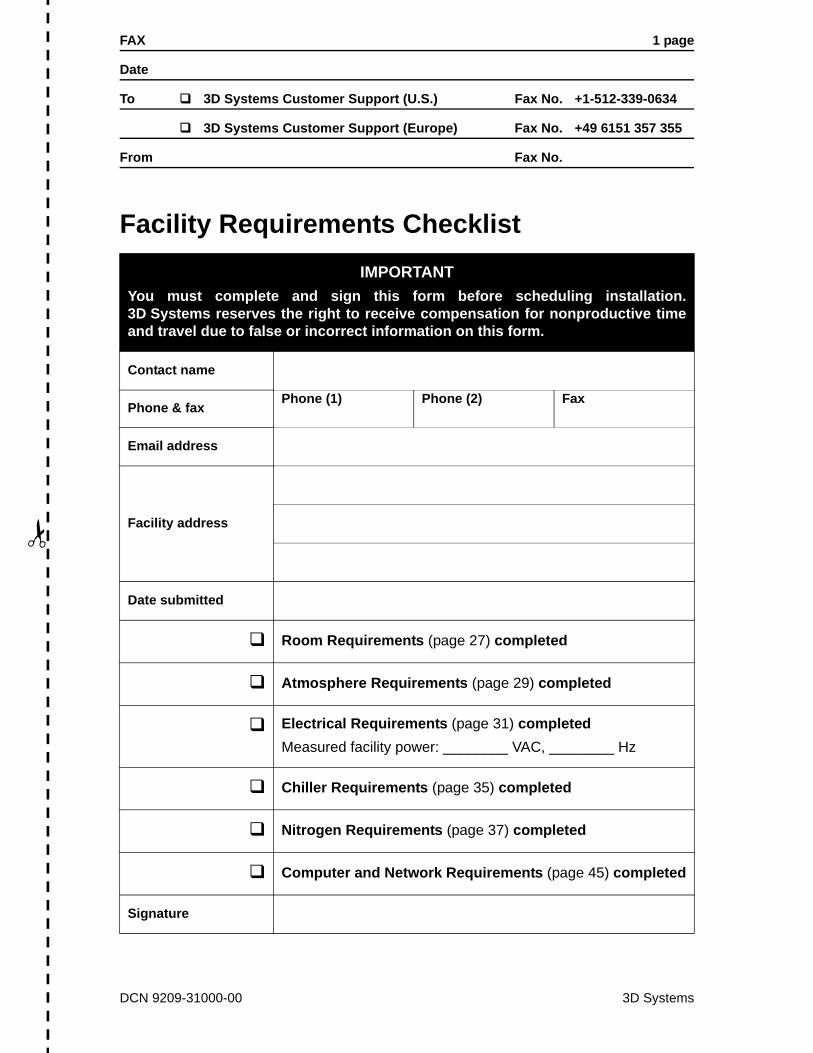
Facility Requirements ChecklistIn the “Requirements” sections that follow, you will find all the requirements your facility must meet before your sPro 60 SLS Center can be installed. After your facility meets all these requirements, complete and sign the “Facility Requirements Checklist” on page 25 and submit it to 3D Systems Customer Support for review.
When Customer Support receives your completed checklist, a 3D Systems representative will contact you to verify your facility’s readiness. When the representative is confident that all facility requirements are met, he or she will schedule a trip to your site to install the sPro 60 SLS Center.
NOTE All facility requirements must be met before 3D Systems Customer Support can schedule a trip to your facility to install the sPro 60 SLS Center.
About the ChecklistEach facility feature on the checklist is covered in order in the subsequent “requirements” sections of this guide. Each of these sections list the specific requirements for a facility feature and any instructions you need to meet them. In some cases, you must refer to the sPro 60 SLS Centers Facility Requirements drawing (DCN 8002-0020); for example, when you lay out the room or wire electrical power. The instructions tell you when you need to refer to this drawing.
After your facility meets all the requirements for a section, check off that section on the Facility Requirements Checklist. If you have any questions regarding facility requirements, contact your 3D Systems Sales representative or 3D Systems Customer Support.
June 2009 DCN 9209-31000-00 23

Facility Requirements Checklist sPro 60 SLS Systems Site Preparation Guide
How to Submit Your Completed Facilities ChecklistSubmit your completed Facility Requirements Checklist by fax, mail, or email to one of the 3D Systems Customer Support sites below. This notifies them that your facility is fully prepared for installation.
Be sure to include the date you submitted your completed checklist so installation can be scheduled as quickly as possible.
If you need to speak to a 3D Systems Customer Support representative about your facility requirements, call:
+1-800-999-5553 (U.S.)+49 6151 357 452 (Europe)+65 430-6681 (Asia Pacific).
NOTE If you plan to use 3D’s LaserForm ST-100 metal material, you must also complete and submit the “Facility Requirements Checklist” for the LaserForm Oven. This checklist is in the “Facility Requirements” section of the separate LaserForm Oven Guide (DCN 8002-20031). You receive this guide when you order a LaserForm Oven.
North & South America; Asia Pacific Europe
Fax +1 512-339-0634attn: SLS Customer Support
+49 6151 357 355attn: SLS Customer Support
3D Systems Corporation333 Three D Systems CircleRock Hill, SC 29730attn: SLS Customer Support
3D Systems GmbHRontgenstrasse 41D-64291 Darmstadt, Germanyattn: SLS Customer Support
Email support@3D Systems-corp.com support@3D Systems-corp.com
24 DCN 9209-31000-00 3D Systems Corporation
FAX 1 page
Date
To 3D Systems Customer Support (U.S.) Fax No. +1-512-339-0634
3D Systems Customer Support (Europe) Fax No. +49 6151 357 355
From Fax No.
✁
Facility Requirements ChecklistIMPORTANT
You must complete and sign this form before scheduling installation.3D Systems reserves the right to receive compensation for nonproductive timeand travel due to false or incorrect information on this form.
Contact name
Phone & faxPhone (1) Phone (2) Fax
Email address
Facility address
Date submitted
Room Requirements (page 27) completed
Atmosphere Requirements (page 29) completed
Electrical Requirements (page 31) completedMeasured facility power: ________ VAC, ________ Hz
Chiller Requirements (page 35) completed
Nitrogen Requirements (page 37) completed
Computer and Network Requirements (page 45) completed
Signature
DCN 9209-31000-00 3D Systems

Facility Requirements Checklist sPro 60 SLS Systems Site Preparation Guide
26 DCN 9209-31000-00 3D Systems Corporation

Room RequirementsSee the sPro 60 SLS Center Facility Requirements drawing (DCN 8002-20020) for room dimensions and forklift requirements.
Clearance Requirements
Floor Requirements
Minimum Clearance Width Depth Height
Room 457 cm (15 ft) 366 cm (12 ft) 305 cm (10 ft)
Access door1
1. Though the process station is only 198 cm (6.5 ft) tall, you need extra height clearance if it is on the pallet.
213 cm (7 ft) – 244 cm (8 ft)
Vibration-free RequiredFirst floor installation
PreferredUncarpetedLevel and flatness within 25.4 mm (1 in) below process station
Distributed load-bearing capacity 0.024 bar (50 psf) on seven 100 mm (4 in) diameter pads
June 2009 DCN 9209-31000-00 27

Room Requirements sPro 60 SLS Systems Site Preparation Guide
28 DCN 9209-31000-00 3D Systems Corporation
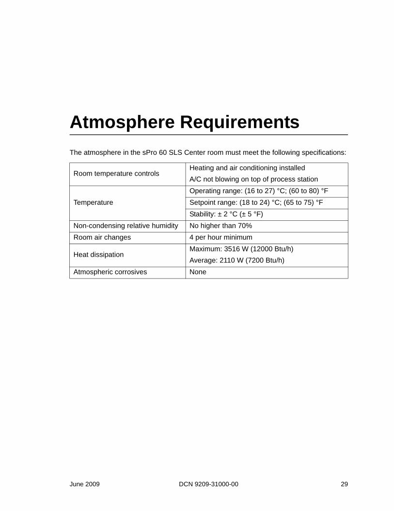
Atmosphere RequirementsThe atmosphere in the sPro 60 SLS Center room must meet the following specifications:
Room temperature controlsHeating and air conditioning installedA/C not blowing on top of process station
Temperature Operating range: (16 to 27) °C; (60 to 80) °FSetpoint range: (18 to 24) °C; (65 to 75) °FStability: ± 2 °C (± 5 °F)
Non-condensing relative humidity No higher than 70%Room air changes 4 per hour minimum
Heat dissipationMaximum: 3516 W (12000 Btu/h)Average: 2110 W (7200 Btu/h)
Atmospheric corrosives None
June 2009 DCN 9209-31000-00 29

Atmosphere Requirements sPro 60 SLS Systems Site Preparation Guide
30 DCN 9209-31000-00 3D Systems Corporation
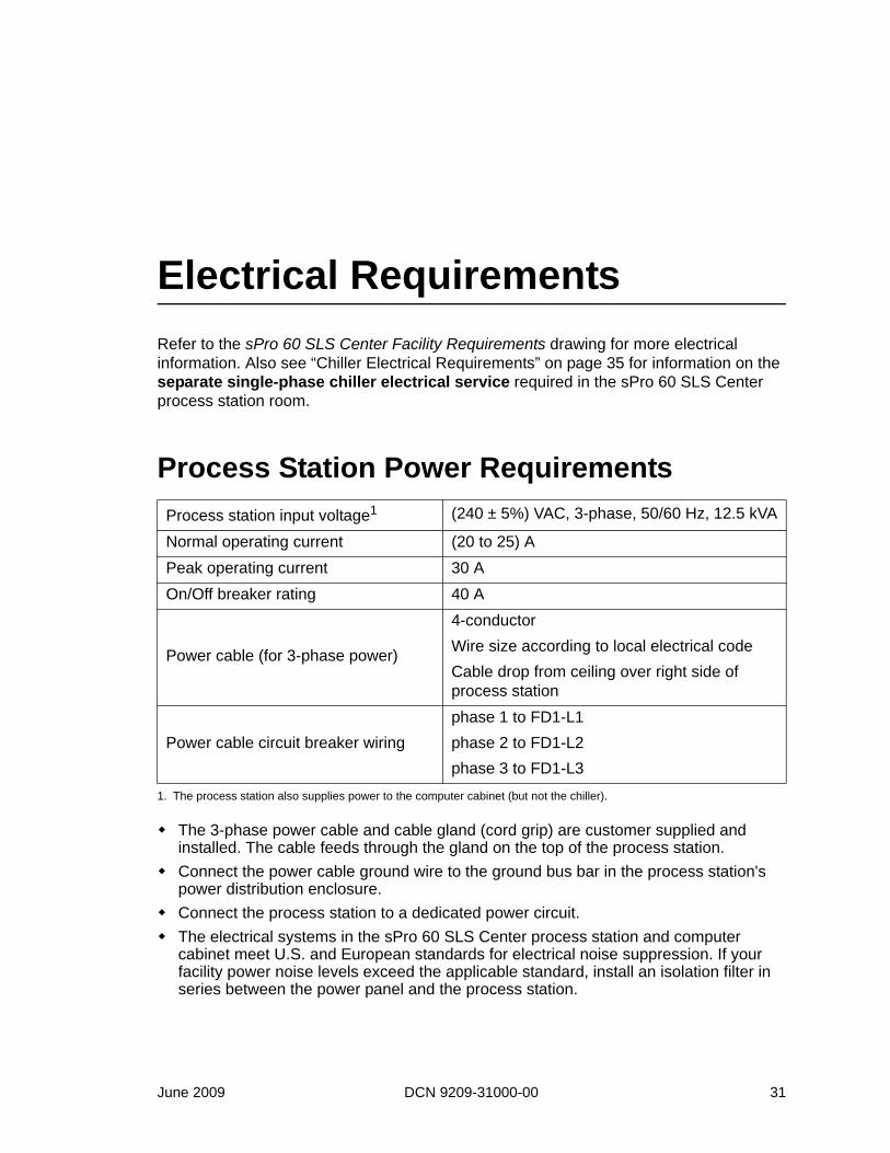
Electrical RequirementsRefer to the sPro 60 SLS Center Facility Requirements drawing for more electrical information. Also see “Chiller Electrical Requirements” on page 35 for information on the separate single-phase chiller electrical service required in the sPro 60 SLS Center process station room.
Process Station Power Requirements
The 3-phase power cable and cable gland (cord grip) are customer supplied and installed. The cable feeds through the gland on the top of the process station. Connect the power cable ground wire to the ground bus bar in the process station's power distribution enclosure. Connect the process station to a dedicated power circuit. The electrical systems in the sPro 60 SLS Center process station and computer cabinet meet U.S. and European standards for electrical noise suppression. If your facility power noise levels exceed the applicable standard, install an isolation filter in series between the power panel and the process station.
Process station input voltage1
1. The process station also supplies power to the computer cabinet (but not the chiller).
(240 ± 5%) VAC, 3-phase, 50/60 Hz, 12.5 kVA
Normal operating current (20 to 25) APeak operating current 30 AOn/Off breaker rating 40 A
Power cable (for 3-phase power)
4-conductorWire size according to local electrical codeCable drop from ceiling over right side of process station
Power cable circuit breaker wiringphase 1 to FD1-L1phase 2 to FD1-L2 phase 3 to FD1-L3
June 2009 DCN 9209-31000-00 31

Electrical Requirements sPro 60 SLS Systems Site Preparation Guide
sPro 60 SLS Center Transformer RequirementsIf the facility does not have 240 VAC, 3-phase, 50/60 Hz, 12.5 kVA power, a customer-supplied step-up or step-down transformer is required.
3D Systems stocks the following four transformers:
If you purchase a transformer from a supplier other than 3D Systems, specify a “delta-to-wye” or “wye-to-wye” primary-to-secondary configuration.Connect the transformer secondary neutral to the transformer secondary ground.
Transformer Purchasing Information
Transformer Type 3D Systems Part No. Output
Step-up 5600-03538 208 to 240 VAC; 3-phase; 60 HzStep-down 5600-03539 400 to 240 VAC; 3 phase; 50 HzStep-down (CE approved) 5600-03539-EUR 400 to 240 VAC; 3 phase; 50 HzStep-down 5600-03768 480 to 240 VAC; 3 phase; 60 Hz
CAUTION!Do not connect the transformer secondary neutral to the process station ground.
Transformer, Step Up, 208/240V, 3-phase, 60 Hz
3D Systems Part Number 5600-035383D Systems Stocked Item Yes
Dimensions (W x H x D)(56 x 41 x 23) cm(22 x 16 x 9) in
Weight 104 kg (230 lb)Voltage 208/240 VAC, 3-phase, 60 Hz, 12.5 kVA3D Systems Warranty Information One year from installation dateNotes Must be purchased through 3D Systems
32 DCN 9209-31000-00 3D Systems Corporation

sPro 60 SLS Systems Site Preparation Guide Electrical Requirements
Transformer, Step Down, 400/240V, 3-phase, 50 Hz
3D Systems Part Number 5600-035393D Systems Stocked Item Yes
Dimensions (W x H x D)(56 x 41 x 23) cm(22 x 16 x 9) in
Weight 127 kg (280 lb)Voltage 400/240 VAC, 3-phase, 60 Hz, 12.5 kVA3D Systems Warranty Information One year from installation dateNotes Must be purchased through 3D Systems
Transformer, Step Down, 400/240V, 3-phase, 50 Hz, CE approved
3D Systems Part Number 5600-03539-EUR3D Systems Stocked Item Yes
Dimensions (W x H x D)(80 x 60 x 75) cm (packed in box)(32 x 24 x 30) in (packed in box)
Weight 127 kg (280 lb)Voltage 400/240V, 3-phase, 50 Hz, 12.5 KVA3D Systems Warranty Information One year from installation date (on parts)Notes Must be purchased through 3D Systems
Transformer, Step Down, 480/240V, 3-phase, 60 Hz
3D Systems Part Number 5600-037683D Systems Stocked Item Yes
Dimensions (W x H x D)(56 x 41 x 23) cm(22 x 16 x 9) in
Weight 127 kg (280 lb)Voltage 480/240 VAC, 3-phase, 60 Hz, 12.5 kVA3D Systems Warranty Information One year from installation dateNotes Must be purchased through 3D Systems
June 2009 DCN 9209-31000-00 33
Electrical Requirements sPro 60 SLS Systems Site Preparation Guide
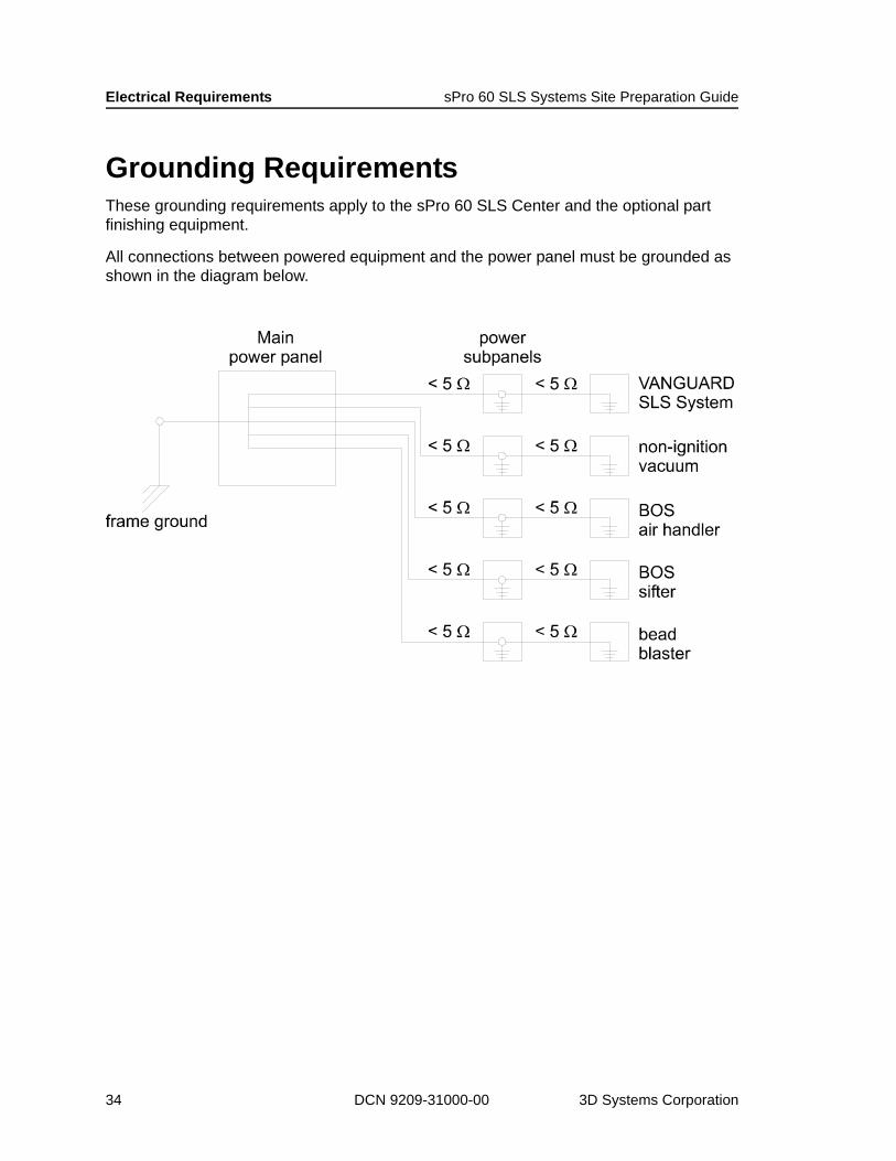
Grounding RequirementsThese grounding requirements apply to the sPro 60 SLS Center and the optional part finishing equipment.
All connections between powered equipment and the power panel must be grounded as shown in the diagram below.
34 DCN 9209-31000-00 3D Systems Corporation
Chiller Requirements
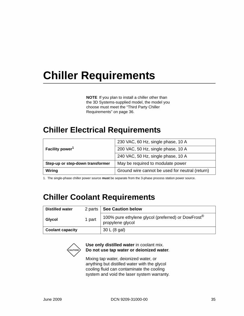
NOTE If you plan to install a chiller other than the 3D Systems-supplied model, the model you choose must meet the “Third Party Chiller Requirements” on page 36.
Chiller Electrical Requirements
Chiller Coolant Requirements
Facility power1
1. The single-phase chiller power source must be separate from the 3-phase process station power source.
230 VAC, 60 Hz, single phase, 10 A200 VAC, 50 Hz, single phase, 10 A240 VAC, 50 Hz, single phase, 10 A
Step-up or step-down transformer May be required to modulate powerWiring Ground wire cannot be used for neutral (return)
Distilled water 2 parts See Caution below
Glycol 1 part 100% pure ethylene glycol (preferred) or DowFrost® propylene glycol
Coolant capacity 30 L (8 gal)
CAUTION!
Use only distilled water in coolant mix. Do not use tap water or deionized water.
Mixing tap water, deionized water, or anything but distilled water with the glycol cooling fluid can contaminate the cooling system and void the laser system warranty.
June 2009 DCN 9209-31000-00 35
Chiller Requirements sPro 60 SLS Systems Site Preparation Guide
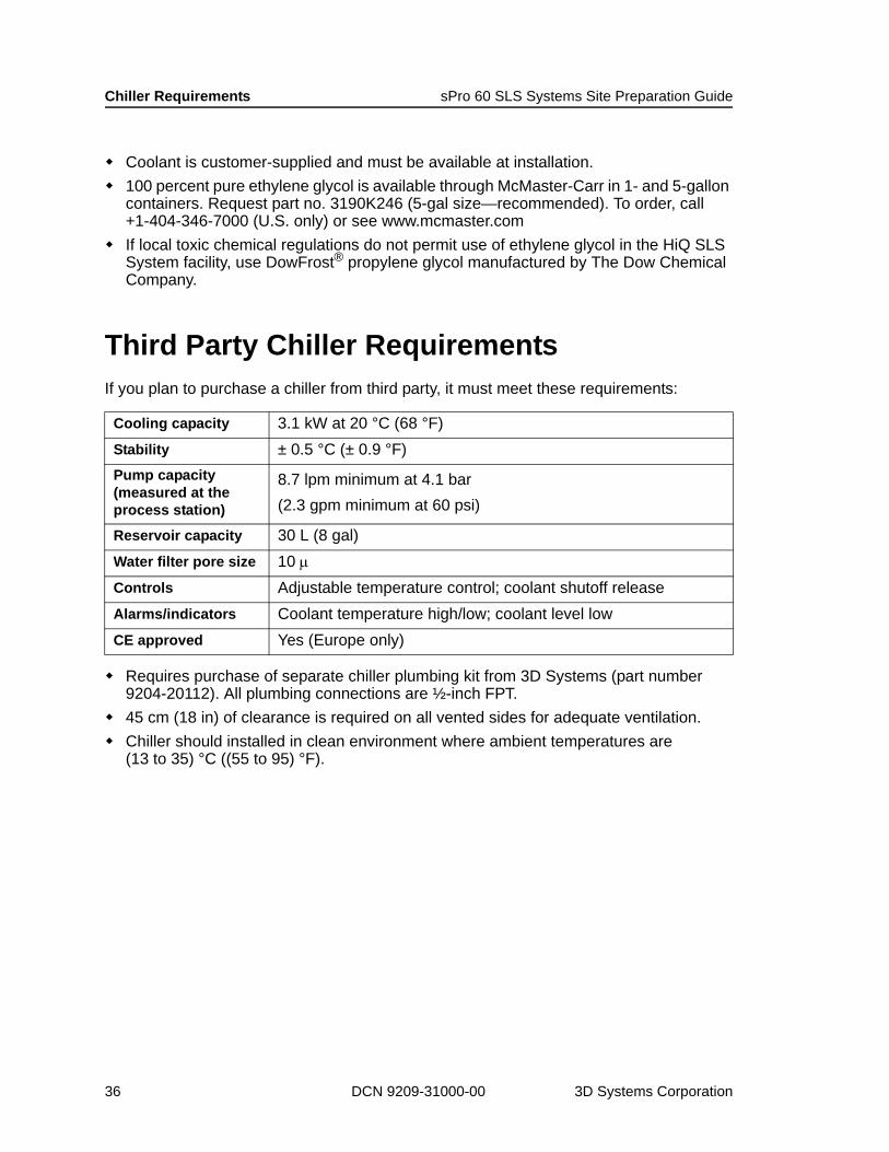
Coolant is customer-supplied and must be available at installation.100 percent pure ethylene glycol is available through McMaster-Carr in 1- and 5-gallon containers. Request part no. 3190K246 (5-gal size—recommended). To order, call +1-404-346-7000 (U.S. only) or see www.mcmaster.comIf local toxic chemical regulations do not permit use of ethylene glycol in the HiQ SLS System facility, use DowFrost® propylene glycol manufactured by The Dow Chemical Company.
Third Party Chiller RequirementsIf you plan to purchase a chiller from third party, it must meet these requirements:
Requires purchase of separate chiller plumbing kit from 3D Systems (part number 9204-20112). All plumbing connections are ½-inch FPT.45 cm (18 in) of clearance is required on all vented sides for adequate ventilation.Chiller should installed in clean environment where ambient temperatures are (13 to 35) °C ((55 to 95) °F).
Cooling capacity 3.1 kW at 20 °C (68 °F)Stability ± 0.5 °C (± 0.9 °F)Pump capacity (measured at the process station)
8.7 lpm minimum at 4.1 bar(2.3 gpm minimum at 60 psi)
Reservoir capacity 30 L (8 gal)Water filter pore size 10 μControls Adjustable temperature control; coolant shutoff releaseAlarms/indicators Coolant temperature high/low; coolant level lowCE approved Yes (Europe only)
36 DCN 9209-31000-00 3D Systems Corporation
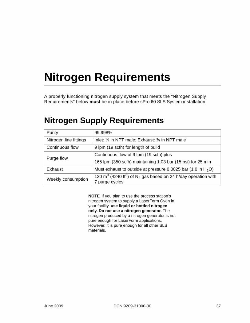
Nitrogen RequirementsA properly functioning nitrogen supply system that meets the “Nitrogen Supply Requirements” below must be in place before sPro 60 SLS System installation.
Nitrogen Supply Requirements
NOTE If you plan to use the process station’s nitrogen system to supply a LaserForm Oven in your facility, use liquid or bottled nitrogen only. Do not use a nitrogen generator. The nitrogen produced by a nitrogen generator is not pure enough for LaserForm applications. However, it is pure enough for all other SLS materials.
Purity 99.998%Nitrogen line fittings Inlet: ¼ in NPT male; Exhaust: ¾ in NPT maleContinuous flow 9 lpm (19 scfh) for length of build
Purge flowContinuous flow of 9 lpm (19 scfh) plus165 lpm (350 scfh) maintaining 1.03 bar (15 psi) for 25 min
Exhaust Must exhaust to outside at pressure 0.0025 bar (1.0 in H2O)
Weekly consumption 120 m3 (4240 ft3) of N2 gas based on 24 h/day operation with 7 purge cycles
June 2009 DCN 9209-31000-00 37

Nitrogen Requirements sPro 60 SLS Systems Site Preparation Guide
Nitrogen Supply OptionsUse one of the following nitrogen supply methods to meet the “Nitrogen Supply Requirements” on page 37:
Liquid or bottled (gaseous) nitrogen with auto-switching manifoldNitrogen generator1
Bulk nitrogen tank
NOTE Nitrogen supply systems are customer supplied and installed. 3D Systems does not service nitrogen supply equipment except for 3D Systems’ Nitrogen generator.
1. Do not use a nitrogen generator for LaserFom applications. The nitrogen produced is not pure enough.
Bulk nitrogen tank Liquid or bottled (gaseous)
nitrogen with auto-switching
manifold
Nitrogen generator
38 DCN 9209-31000-00 3D Systems Corporation

sPro 60 SLS Systems Site Preparation Guide Nitrogen Requirements
Liquid or Bottled (Gaseous) Nitrogen
Nitrogen dewars: If you plan to run only one machine, portable liquid or bottled nitrogen tanks (dewars) will probably be sufficient. Install at least two dewars and connect them with an auto-switching manifold. The manifold will ensure a constant nitrogen supply during builds.Bulk nitrogen tank: If you plan to run two or more machines, consider a fixed bulk liquid nitrogen tank.
Nitrogen dewars with auto-switching manifold
Bulk liquid nitrogen tanks
June 2009 DCN 9209-31000-00 39
Nitrogen Requirements sPro 60 SLS Systems Site Preparation Guide
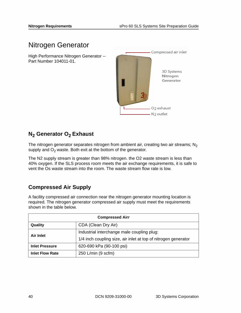
Nitrogen GeneratorHigh Performance Nitrogen Generator --Part Number 104011-01.
N2 Generator O2 Exhaust
The nitrogen generator separates nitrogen from ambient air, creating two air streams; N2 supply and O2 waste. Both exit at the bottom of the generator.
The N2 supply stream is greater than 98% nitrogen. the O2 waste stream is less than 40% oxygen. If the SLS process room meets the air exchange requirements, it is safe to vent the Os waste stream into the room. The waste stream flow rate is low.
Compressed Air SupplyA facility compressed air connection near the nitrogen generator mounting location is required. The nitrogen generator compressed air supply must meet the requirements shown in the table below.
Compressed Airr
Quality CDA (Clean Dry Air)
Air InletIndustrial interchange male coupling plug:1/4 inch coupling size, air inlet at top of nitrogen generator
Inlet Pressure 620-690 kPa (90-100 psi)Inlet Flow Rate 250 L/min (9 scfm)
40 DCN 9209-31000-00 3D Systems Corporation

sPro 60 SLS Systems Site Preparation Guide Nitrogen Requirements
Nitrogen Supply and Exhaust LinesNitrogen supply and exhaust lines must be in place before sPro 60 SLS System installation. Follow these guidelines for nitrogen supply and exhaust lines:
Route nitrogen supply lines through the ceiling.Locate the drops over the left side of the process station (viewed from the front).Use a ¼ inch female NPT female fitting on the nitrogen inlet line.Use a ¾ inch female NPT fitting on the nitrogen exhaust line.Do not use a fan on the nitrogen exhaust line.
NOTE Keep the nitrogen lines—especially the exhaust line—as short as possible to ensure proper pressure.
June 2009 DCN 9209-31000-00 41

Nitrogen Requirements sPro 60 SLS Systems Site Preparation Guide
42 DCN 9209-31000-00 3D Systems Corporation
Receiving and Moving the SystemThis chapter tells you what you will receive in your sPro 60 SLS Center shipment and how to unload and unpack the various system components. It also tells you how to properly move the system to prevent damage.
Before you move the sPro 60 SLS Center, verify the following:
Room is large enough to allow specified clearance around all sides of the process station, chiller, and computer cabinet.
Floor below sPro 60 SLS Center meets the “Floor Requirements” on page 27.
Process station on pallet jack or forklift will fit through all doorways leading to the installation room.
NOTE Refer to the sPro 60 SLS Center Facility Requirements drawing (DCN 8002-20020) for illustrated dimension and clearance information.
June 2009 DCN 9209-31000-00 43

Receiving and Moving the System sPro 60 SLS Center Site Preparation Guide
What Your Shipment IncludesAll possible components of a 3D Systems rapid prototyping system are listed below. They include a sPro 60 SLS Center for building the parts, peripheral equipment for part finishing, and items consumed during part builds such as powder and filters.
Required and Optional System ComponentsRequired sPro 60 SLS Center Components
Component Supplier Comment
Process station 3D SystemsRequires a 3-phase power source and a separate chiller with its own single phase power source.
User Interface 3D Systems Shipped in separate boxesIncludes monitor, keyboard, and mouse
Chiller 3D Systems or third party
3D Systems stocks a recommended chiller and ships it with the system.
Nitrogen supply3D Systems or third party
Can use nitrogen tank(s) or a nitrogen generator depending on consumption/application.
Non-ignition vacuum cleaner
3D Systems or third party
For cleaning the process station between builds.
LaserForm Oven(optional)
3D SystemsSee the “Facility Requirements” section in the separate LaserForm Oven Guide (DCN 8002-20031)
Convection Oven(optional)
3D Systems or third party Required for SandForm material only
44 DCN 9209-31000-00 3D Systems Corporation
sPro 60 SLS Center Site Preparation Guide Receiving and Moving the System
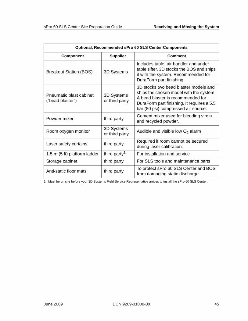
Optional, Recommended sPro 60 SLS Center Components
Component Supplier Comment
Breakout Station (BOS) 3D Systems
Includes table, air handler and under-table sifter. 3D stocks the BOS and ships it with the system. Recommended for DuraForm part finishing.
Pneumatic blast cabinet (“bead blaster”)
3D Systems or third party
3D stocks two bead blaster models and ships the chosen model with the system. A bead blaster is recommended for DuraForm part finishing. It requires a 5.5 bar (80 psi) compressed air source.
Powder mixer third party Cement mixer used for blending virgin and recycled powder.
Room oxygen monitor 3D Systems or third party Audible and visible low O2 alarm
Laser safety curtains third party Required if room cannot be secured during laser calibration.
1.5 m (5 ft) platform ladder third party1 For installation and serviceStorage cabinet third party For SLS tools and maintenance parts
Anti-static floor mats third party To protect sPro 60 SLS Center and BOS from damaging static discharge
1. Must be on site before your 3D Systems Field Service Representative arrives to install the sPro 60 SLS Center.
June 2009 DCN 9209-31000-00 45

Receiving and Moving the System sPro 60 SLS Center Site Preparation Guide
SLS Materials and FiltersThe materials and filters you receive in your sPro 60 SLS Center shipment depend on your SLS application. All available materials and filters are listed below.
SLS materials
DuraForm™ PADuraForm™ GFDuraForm™ FlexDuraForm™ AFDuraForm™ EX BlackDuraForm™ EX NaturalDuraForm™ HS-10 General PurposeDuraForm™ HS-10 StiffBronze InfiltrantAlumina PowderCastForm™ PSLaserForm ST-100™LaserForm A6
Filters
Process chamber filter (fiberglass)Process chamber duct filter (charcoal)Nitrogen exhaust filter (cellulose)IR block coolant filterChiller filter (if chiller is purchased from 3D Systems)LaserForm Oven electrical box intake fan filter (if LaserForm Oven is purchased)
46 DCN 9209-31000-00 3D Systems Corporation
sPro 60 SLS Center Site Preparation Guide Receiving and Moving the System
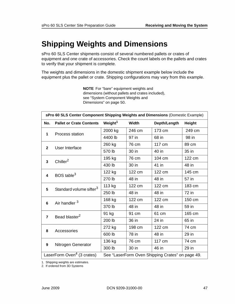
Shipping Weights and DimensionssPro 60 SLS Center shipments consist of several numbered pallets or crates of equipment and one crate of accessories. Check the count labels on the pallets and crates to verify that your shipment is complete.
The weights and dimensions in the domestic shipment example below include the equipment plus the pallet or crate. Shipping configurations may vary from this example.
NOTE For “bare” equipment weights and dimensions (without pallets and crates included), see “System Component Weights and Dimensions” on page 50.
sPro 60 SLS Center Component Shipping Weights and Dimensions (Domestic Example)
No. Pallet or Crate Contents Weight1
1. Shipping weights are estimates.
Width Depth/Length Height
1 Process station2000 kg 246 cm 173 cm 249 cm4400 lb 97 in 68 in 98 in
2 User Interface260 kg 76 cm 117 cm 89 cm570 lb 30 in 40 in 35 in
3 Chiller2
2. If ordered from 3D Systems
195 kg 76 cm 104 cm 122 cm430 lb 30 in 41 in 48 in
4 BOS table3 122 kg 122 cm 122 cm 145 cm270 lb 48 in 48 in 57 in
5 Standard volume sifter3 113 kg 122 cm 122 cm 183 cm250 lb 48 in 48 in 72 in
6 Air handler 3168 kg 122 cm 122 cm 150 cm370 lb 48 in 48 in 59 in
7 Bead blaster291 kg 91 cm 61 cm 165 cm200 lb 36 in 24 in 65 in
8 Accessories272 kg 198 cm 122 cm 74 cm600 lb 78 in 48 in 29 in
9 Nitrogen Generator136 kg 76 cm 117 cm 74 cm300 lb 30 in 46 in 29 in
LaserForm Oven4 (3 crates) See “LaserForm Oven Shipping Crates” on page 49.
June 2009 DCN 9209-31000-00 47

Receiving and Moving the System sPro 60 SLS Center Site Preparation Guide
Accessories CrateOne “Accessories crate” containing the items listed below ships with the sPro 60 SLS Center.
NOTE If you ordered extra SLS materials or equipment, your shipment will also include one or two extra crates or pallets. (Crates for air shipments; pallets for ground shipments.)
Ship Group BoxThe “Ship Group” box in the “Accessories” crate contains the following items:
3. BOS, sifter, and air handler are not used in LaserForm applications.4. LaserForm ST-100 applications only
sPro 60 SLS Center Accessories Crate Contents with Shipping Weights and Dimensions
Accessories Crate Item Weight1
1. Shipping weights are estimates.
Width Depth/Length Height
“Ship Group” box (contents listed below)
272 kg 198 cm 122 cm 74 cm600 lb 78 in 48 in 29 in
sPro 60 SLS Center Ship Group Box Contents
Qty Description
1 sPro 60 SLS Center Application Software CD-ROM1 sPro 60 SLS Center Application Software release notes1 Magics RP software CD-ROM1 Material Safety Data Sheet (MSDS) for every 3D-supplied material in shipment2 Replacement process chamber halogen lamps
12 Replacement fiberglass process chamber filters3 Replacement charcoal process chamber duct filter pads2 Replacement cellulose nitrogen exhaust sediment filters1 Part transfer container1 Feed transfer container1 Part transfer tray
48 DCN 9209-31000-00 3D Systems Corporation

sPro 60 SLS Center Site Preparation Guide Receiving and Moving the System
LaserForm Oven Shipping CratesIf you order a LaserForm Oven, it arrives in three additional crates with the following weights and sizes. (See the “Facility Requirements” section of the LaserForm Oven Guide (DCN 8002-20031) for more information.)
1 Feed transfer tray1 Laser window plug1 Powder scoop1 Dust cloth2 Foam swabs2 Boxes of lens cleaning tissue1 Metric hex wrench1 Bottle of ethanol1 Nylon bristle paint brush
LaserForm Oven Shipping Weights and Dimensions
Crate 1 Oven Frame (165 x 160 x 234) cm(65 x 63 x 92) in 399 kg (880 lb)
Crate 2 Oven Retort (137 x 137 x 150) cm(54 x 54 x 59) in 127 kg (280 lb)
Crate 3 Oven Kiln (114 x 114 x 132) cm(45 x 45 x 52) in 209 kg (460 lb)
sPro 60 SLS Center Ship Group Box Contents (continued)
Qty Description
June 2009 DCN 9209-31000-00 49
Receiving and Moving the System sPro 60 SLS Center Site Preparation Guide
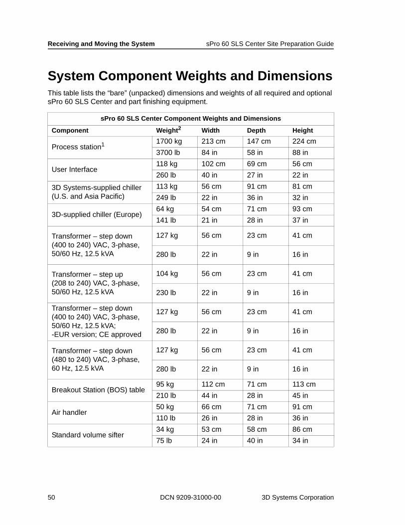
System Component Weights and DimensionsThis table lists the “bare” (unpacked) dimensions and weights of all required and optional sPro 60 SLS Center and part finishing equipment.
sPro 60 SLS Center Component Weights and Dimensions
Component Weight2 Width Depth Height
Process station1 1700 kg 213 cm 147 cm 224 cm3700 lb 84 in 58 in 88 in
User Interface118 kg 102 cm 69 cm 56 cm260 lb 40 in 27 in 22 in
3D Systems-supplied chiller (U.S. and Asia Pacific)
113 kg 56 cm 91 cm 81 cm249 lb 22 in 36 in 32 in
3D-supplied chiller (Europe)64 kg 54 cm 71 cm 93 cm141 lb 21 in 28 in 37 in
Transformer – step down(400 to 240) VAC, 3-phase, 50/60 Hz, 12.5 kVA
127 kg 56 cm 23 cm 41 cm
280 lb 22 in 9 in 16 in
Transformer – step up(208 to 240) VAC, 3-phase, 50/60 Hz, 12.5 kVA
104 kg 56 cm 23 cm 41 cm
230 lb 22 in 9 in 16 in
Transformer – step down(400 to 240) VAC, 3-phase, 50/60 Hz, 12.5 kVA;-EUR version; CE approved
127 kg 56 cm 23 cm 41 cm
280 lb 22 in 9 in 16 in
Transformer – step down(480 to 240) VAC, 3-phase, 60 Hz, 12.5 kVA
127 kg 56 cm 23 cm 41 cm
280 lb 22 in 9 in 16 in
Breakout Station (BOS) table95 kg 112 cm 71 cm 113 cm210 lb 44 in 28 in 45 in
Air handler 50 kg 66 cm 71 cm 91 cm110 lb 26 in 28 in 36 in
Standard volume sifter34 kg 53 cm 58 cm 86 cm75 lb 24 in 40 in 34 in
50 DCN 9209-31000-00 3D Systems Corporation

sPro 60 SLS Center Site Preparation Guide Receiving and Moving the System
High volume sifter136 kg 53 cm 53 cm 122 cm300 lb 21 in 21 in 48 in
Bead blaster (U.S. and Asia Pacific only)
68 kg 66 cm 102 cm 160 cm150 lb 26 in 40 in 63 in
Nitrogen generator113 kg 25 cm 56 cm 97 cm
250 lb 10 in 22 in 38 in
Non-ignition vacuum cleaner32 kg 53 cm 53 cm 94 cm70 lb 21 in 21 in 37 in
Forced convection ovensingle phase; 110 VAC, 60 Hz or 240 VAC 50/60 Hz (U.S. and Asia Pacific only)
133 kg 91 cm 58 cm 122 cm
294 lb 36 in 23 in 48 in
LaserForm Oven (assembled)630 kg 137 cm 142 cm 208 cm1390 lb 54 in 56 in 82 in
1. Process station dimensions and weight include panels2. estimated
sPro 60 SLS Center Component Weights and Dimensions (continued)
Component Weight2 Width Depth Height
June 2009 DCN 9209-31000-00 51
Receiving and Moving the System sPro 60 SLS Center Site Preparation Guide
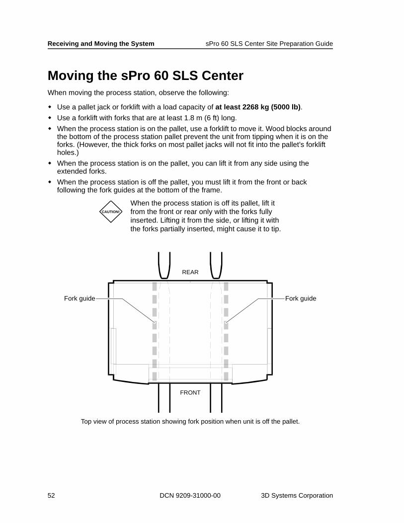
Moving the sPro 60 SLS CenterWhen moving the process station, observe the following:
Use a pallet jack or forklift with a load capacity of at least 2268 kg (5000 lb).Use a forklift with forks that are at least 1.8 m (6 ft) long.When the process station is on the pallet, use a forklift to move it. Wood blocks around the bottom of the process station pallet prevent the unit from tipping when it is on the forks. (However, the thick forks on most pallet jacks will not fit into the pallet’s forklift holes.)When the process station is on the pallet, you can lift it from any side using the extended forks. When the process station is off the pallet, you must lift it from the front or back following the fork guides at the bottom of the frame.
CAUTION!
When the process station is off its pallet, lift it from the front or rear only with the forks fully inserted. Lifting it from the side, or lifting it with the forks partially inserted, might cause it to tip.
FRONT
REAR
Fork guide Fork guide
Top view of process station showing fork position when unit is off the pallet.
52 DCN 9209-31000-00 3D Systems Corporation
sPro 60 SLS Center Site Preparation Guide Receiving and Moving the System
Moving SequenceUse the pallet jack to remove the chiller and computer cabinet from the truck.
1. Use the forklift to remove the process station from the truck.
2. Use the forklift to lift the components off their pallets or crate bottoms.
3. Use the pallet jack to move the process station into place.
4. Unlock the front wheels on the chiller and computer cabinet and roll them into place.
Place the computer cabinet on the right side of the process station and the chiller on the left.
sPro 60 SLS Center Placement3D Systems Customer Support can advise you on sPro 60 SLS Center equipment placement before installation. Also refer to the sPro 60 SLS Centers Facilities Requirements drawing (DCN 8002-20020). Be sure to meet the “Clearance Requirements” on page 27 so there will be sufficient room for air circulation and service/operator access.
CAUTION!
Do not use a forklift with standard-length forks to move the process station; use 1.8 m (6 ft) long forks. (The front of the process station is much heavier than the back and it can tip.)
CAUTION!
Make sure the pallet jack forks are between the fork guides before lifting/moving.
Do not move or lift the process station from its sides.
June 2009 DCN 9209-31000-00 53
Receiving and Moving the System sPro 60 SLS Center Site Preparation Guide
Installation Verifications (performed by 3D Systems)Once all the sPro 60 SLS Center equipment is in place, your 3D Systems Field Service Representative will make the required nitrogen, power, and coolant hook-ups and connections. He will also level the process station, then perform the following verification procedures:
Complete machine module functional testsVerify functionality of safety interlocksVerify calibration of componentsBuild an acceptance test part to ensure system function
54 DCN 9209-31000-00 3D Systems Corporation
Part Finishing Area Facilities RequirementsThis section describes the facility requirements and 3D Systems-recommended third party equipment for your part finishing area. If you have questions about third party maintenance and part finishing equipment, contact 3D Systems for additional product information.
Part Finishing and Maintenance Equipment List
BOS Air HandlerVibratory Sifter A 1.5-m (5-ft) platform ladder for installation and serviceA glass bead blaster to clean sintered parts (requires a source of compressed air of at least 5.5 bar (80 psi))A storage cabinet for maintenance partsAnti-static mats for the floor around the sPro 60 SLS Center and the BOS.
June 2009 DCN 9209-31000-00 55
Part Finishing Area Facilities Requirements sPro 60 SLS Center Site Preparation Guide
er
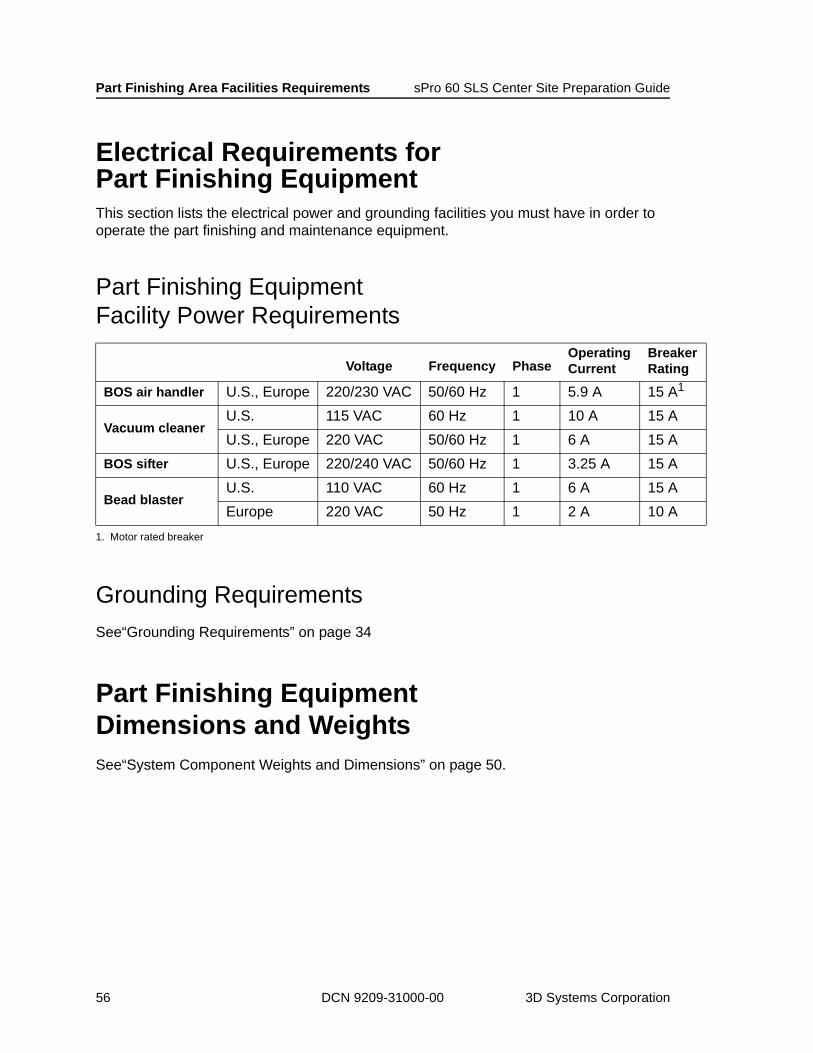
Electrical Requirements for Part Finishing EquipmentThis section lists the electrical power and grounding facilities you must have in order to operate the part finishing and maintenance equipment.
Part Finishing Equipment Facility Power Requirements
Grounding RequirementsSee“Grounding Requirements” on page 34
Part Finishing Equipment Dimensions and WeightsSee“System Component Weights and Dimensions” on page 50.
Voltage Frequency PhaseOperatingCurrent
BreakRating
BOS air handler U.S., Europe 220/230 VAC 50/60 Hz 1 5.9 A 15 A1
1. Motor rated breaker
Vacuum cleanerU.S. 115 VAC 60 Hz 1 10 A 15 AU.S., Europe 220 VAC 50/60 Hz 1 6 A 15 A
BOS sifter U.S., Europe 220/240 VAC 50/60 Hz 1 3.25 A 15 A
Bead blasterU.S. 110 VAC 60 Hz 1 6 A 15 AEurope 220 VAC 50 Hz 1 2 A 10 A
56 DCN 9209-31000-00 3D Systems Corporation

sPro 60 SLS Center Site Preparation Guide Part Finishing Area Facilities Requirements
BOS, Sifter, and Air Handler Dimensions
1118 mm(44 in)
610 mm(24 in)
711 mm(28 in) BOS table
Top View
Sifter(below)
Air hose( ) above floor610 mm 24 in
Air HandlerTop Viewpwr
sw.pwrsw.
610 mm(24 in)
686 mm(27 in)
1118 mm(44 in)
1448 mm(57 in)
BOS tableFront View
Sifter
Front view of BOS table showing sifter under the BOS table. (Air handler also shown on the right side of the photo below.)
June 2009 DCN 9209-31000-00 57

Part Finishing Area Facilities Requirements sPro 60 SLS Center Site Preparation Guide
BOS Component Purchasing InformationThis section provides purchasing information for the following third-party 3D Systems BOS components:
Standard volume sifterHigh volume sifter (optional)Air handler
3D Systems supplies the BOS table (part number 9201-20681).
Standard Volume Sifter Purchasing Information
Standard Volume Sifter(U.S. and Asia Pacific)
3D Systems Part Number 9201-20683
3D Systems Stocked Item Yes
Specifications/Requirements
Dimensions (W x D x H)
(61 x 102 x 86) cm(24 x 40 x 34) in
Weight 34 kg (75 lb)Sifting rate > 2.9 kg (6.5 lb)/min (Duraform PA)Screens One 70 TBC and one 94 TBC
Facility power220/240 VAC, single phase, 50/60 Hz, 1.4 A (15% reduction at 50 Hz)
FeaturesFour castersPower switch and 3 m (10 ft) power cord without plug
Warranty Information One year
NotesThis sifter fits under the 3D Systems BOS table.Contact 3D Systems for replacement screens.
Standard volume sifter
High volume sifter
Air handler
58 DCN 9209-31000-00 3D Systems Corporation
sPro 60 SLS Center Site Preparation Guide Part Finishing Area Facilities Requirements
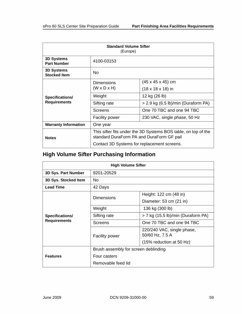
High Volume Sifter Purchasing Information
Standard Volume Sifter(Europe)
3D Systems Part Number 4100-03153
3D Systems Stocked Item No
Specifications/Requirements
Dimensions (W x D x H)
(45 x 45 x 45) cm(18 x 18 x 18) in
Weight 12 kg (26 lb)Sifting rate > 2.9 kg (6.5 lb)/min (Duraform PA)Screens One 70 TBC and one 94 TBCFacility power 230 VAC, single phase, 50 Hz
Warranty Information One year
NotesThis sifter fits under the 3D Systems BOS table, on top of the standard DuraForm PA and DuraForm GF pailContact 3D Systems for replacement screens.
High Volume Sifter
3D Sys. Part Number 9201-205293D Sys. Stocked Item NoLead Time 42 Days
Specifications/Requirements
DimensionsHeight: 122 cm (48 in)Diameter: 53 cm (21 in)
Weight 136 kg (300 lb)Sifting rate > 7 kg (15.5 lb)/min (Duraform PA)Screens One 70 TBC and one 94 TBC
Facility power220/240 VAC, single phase, 50/60 Hz, 7.5 A (15% reduction at 50 Hz)
Features
Brush assembly for screen deblindingFour castersRemovable feed lid
June 2009 DCN 9209-31000-00 59
Part Finishing Area Facilities Requirements sPro 60 SLS Center Site Preparation Guide
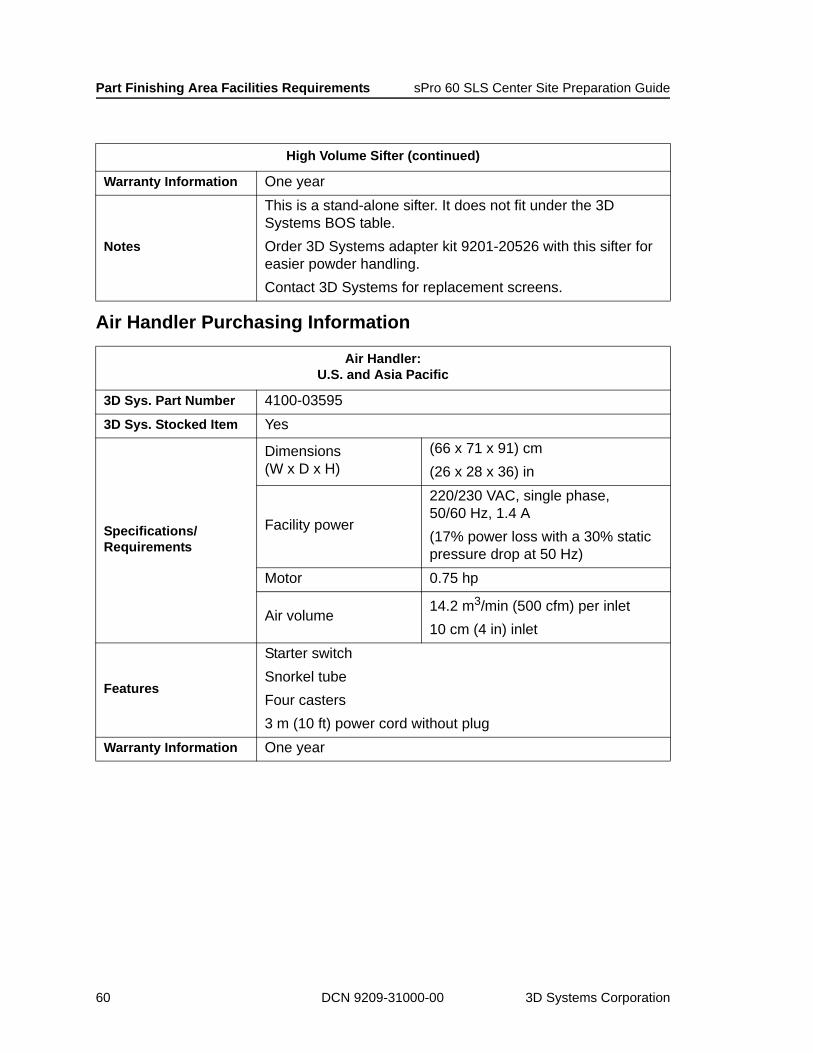
Air Handler Purchasing Information
Warranty Information One year
Notes
This is a stand-alone sifter. It does not fit under the 3D Systems BOS table. Order 3D Systems adapter kit 9201-20526 with this sifter for easier powder handling. Contact 3D Systems for replacement screens.
Air Handler:U.S. and Asia Pacific
3D Sys. Part Number 4100-035953D Sys. Stocked Item Yes
Specifications/Requirements
Dimensions (W x D x H)
(66 x 71 x 91) cm(26 x 28 x 36) in
Facility power
220/230 VAC, single phase, 50/60 Hz, 1.4 A (17% power loss with a 30% static pressure drop at 50 Hz)
Motor 0.75 hp
Air volume14.2 m3/min (500 cfm) per inlet 10 cm (4 in) inlet
Features
Starter switchSnorkel tubeFour casters3 m (10 ft) power cord without plug
Warranty Information One year
High Volume Sifter (continued)
60 DCN 9209-31000-00 3D Systems Corporation

sPro 60 SLS Center Site Preparation Guide Part Finishing Area Facilities Requirements
Air Handler:Europe
3D Sys. Part Number 9100-20200-EUR3D Sys. Stocked Item Yes
Specifications/Requirements
Dimensions (crated)(W x D x H)
(115 x 115 x 195) cm(45 x 45 x 77) in
Dimensions (actual) (W x D x H)
(66 x 71 x 91) cm(26 x 28 x 36) in
Weight 160 kg (353 lb)Facility power 400 VAC, single-phase, 50 Hz, 16 A Motor 0.75 hp
Air volume14.2 m3/min (500 cfm) per inlet 10 cm (4 in) inlet
Features
Starter switchSnorkel tubeFour casters3 m (10 ft) power cord without plug
Warranty Information One year parts and service, except for shipping cost (Europe only)
June 2009 DCN 9209-31000-00 61
Part Finishing Area Facilities Requirements sPro 60 SLS Center Site Preparation Guide
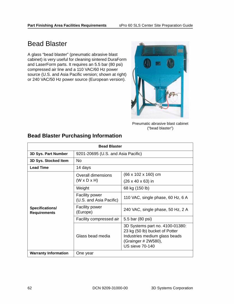
Bead BlasterA glass “bead blaster” (pneumatic abrasive blast cabinet) is very useful for cleaning sintered DuraForm and LaserForm parts. It requires an 5.5 bar (80 psi) compressed air line and a 110 VAC/60 Hz power source (U.S. and Asia Pacific version; shown at right) or 240 VAC/50 Hz power source (European version).
Bead Blaster Purchasing Information
Bead Blaster
3D Sys. Part Number 9201-20695 (U.S. and Asia Pacific)3D Sys. Stocked Item NoLead Time 14 days
Specifications/Requirements
Overall dimensions (W x D x H)
(66 x 102 x 160) cm(26 x 40 x 63) in
Weight 68 kg (150 lb)Facility power (U.S. and Asia Pacific) 110 VAC, single phase, 60 Hz, 6 A
Facility power (Europe) 240 VAC, single phase, 50 Hz, 2 A
Facility compressed air 5.5 bar (80 psi)
Glass bead media
3D Systems part no. 4100-01380: 23 kg (50 lb) bucket of Potter Industries medium glass beads (Grainger # 2W580), US sieve 70-140
Warranty Information One year
Pneumatic abrasive blast cabinet(“bead blaster”)
62 DCN 9209-31000-00 3D Systems Corporation

sPro 60 SLS Center Site Preparation Guide Part Finishing Area Facilities Requirements
LaserForm OvenSee the “Facilities” section in the LaserForm Oven Guide (DCN 8002-20031).
CastForm Forced Convection OvenThis section provides specifications and purchasing information for the SandForm/CastForm Forced Convection Oven manufactured by the Lindberg / Blue M division of Cole-Parmer Instrument Co.
3D Systems recommends this oven for curing SandForm parts and infiltrating CastForm parts. It is available in a 110 VAC 60 Hz or 240 VAC 50/60 Hz model.
NOTE The Forced Convection Oven is not CE-approved.
Forced convection oven for CastForm materials. (U.S. and Asia
Pacific Only)
June 2009 DCN 9209-31000-00 63

Part Finishing Area Facilities Requirements sPro 60 SLS Center Site Preparation Guide
CastForm Forced Convection Oven Purchasing Information
Forced Convection Oven, 110 VAC, single phase, 60 Hz
3D Systems Part Number 5300-03146
3D Systems Stocked Item No
Lead Time 30 days
Specifications/Requirements
Overall dimensions (W x D x H)
(91 x 58 x 123) cm(36 x 23 x 48) in
Chamber dimensions (W x D x H)
(56 x 41 x 64) cm(22 x 16 x 25) in
Capacity 0.14 m3 (5.0 ft3)Weight 133 kg (294 lb)
Facility power 110 VAC, single phase, 60 Hz, 17.5 A
Temperature range(40 to 300) °C (104 to 572) °F
Uniformity ± 1.0 °C at 200 °C (± 1.8 °F at 392 °F)
FeaturesDouble wall constructionSingle set point–programmable
Warranty Information One year
64 DCN 9209-31000-00 3D Systems Corporation
sPro 60 SLS Center Site Preparation Guide Part Finishing Area Facilities Requirements
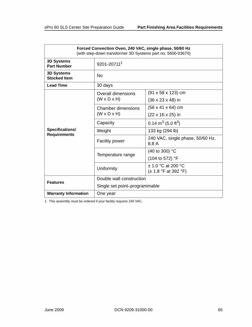
Forced Convection Oven, 240 VAC, single phase, 50/60 Hz(with step-down transformer 3D Systems part no. 5600-03670)
3D Systems Part Number 9201-207111
3D Systems Stocked Item No
Lead Time 30 days
Specifications/Requirements
Overall dimensions (W x D x H)
(91 x 58 x 123) cm(36 x 23 x 48) in
Chamber dimensions (W x D x H)
(56 x 41 x 64) cm(22 x 16 x 25) in
Capacity 0.14 m3 (5.0 ft3)Weight 133 kg (294 lb)
Facility power 240 VAC, single phase, 50/60 Hz, 8.8 A
Temperature range(40 to 300) °C (104 to 572) °F
Uniformity ± 1.0 °C at 200 °C (± 1.8 °F at 392 °F)
FeaturesDouble wall constructionSingle set point–programmable
Warranty Information One year1. This assembly must be ordered if your facility requires 240 VAC.
June 2009 DCN 9209-31000-00 65

Part Finishing Area Facilities Requirements sPro 60 SLS Center Site Preparation Guide
66 DCN 9209-31000-00 3D Systems Corporation
SafetyFollowing the safety recommendations and guidelines in this chapter when preparing your facility for Sinsterstation installation.
General Operator Safety InformationBefore using the sPro 60 SLS Center, your company should have a safety program in place. The safety program should do the following:
Label and point out hazardous equipment, materials, and procedures.Explain what to do in an emergency situation.Provide information about the hazards of equipment and materials in the form of warning labels, signs, and Material Safety Data Sheets (MSDS). 3D Systems provides the MSDS’s for the powdered materials used with the sPro 60 SLS Center.Include the installation of a room area oxygen sensor with audible and visible alarms—with optional connections to the process station’s nitrogen system safety interlocks.
Environmental Venting InformationEnvironmental venting is required where the sPro 60 SLS Center operates for three reasons:
1. To control waste heat created by SLS operations
2. To prevent nitrogen from displacing oxygen in the work area
3. To prevent excessive concentrations of airborne SLS material and SLS combustion off-gasses from accumulating in the work area
Waste Heat VentingWaste heat venting is required for the normal operation of the sPro 60 SLS Center in a room that meets or exceeds the recommended room specifications. See “Atmosphere Requirements” on page 29.
June 2009 DCN 9209-31000-00 67

Safety sPro 60 SLS Systems Site Preparation Guide
Nitrogen VentingNitrogen must be vented from the process station by a ¾-inch diameter NPT pipe fitting with an exhaust pressure of less than 25.4 mm H2O (1.00 inches H2O). See “Nitrogen Supply and Exhaust Lines” on page 41 for more information.
SLS Material Combustion Off-Gas and Airborne Dust ControlAll SLS materials and operations have been evaluated for environmental exposure safety by a certified industrial hygienist1. The “Industrial Hygiene Surveys” and Material Safety Data Sheets (MSDS’s) for 3D Systems SLS materials are excellent sources of occupational health information and exposure control recommendations.
The industrial hygiene survey reports conclude that occupational exposures to SLS materials and combustion off-gasses during SLS operations are well below allowable OSHA2 and ACGIH3 limits. These reports assume that the SLS system has been installed correctly and that the facility meets all the requirements in this guide.
Contact 3D Systems Customer Support at +1-800-999-5553 if you wish to obtain copies of the Industrial Hygiene Surveys and MSDSs for the SLS materials you use.
1. All SLS material industrial hygiene surveys were performed by Southwest Research Institute, P.O. Drawer 28510, 6220 Culebra Road, San Antonio, Texas 78228-0510 U.S.A.
2. Occupational Safety and Health Administration
3. American Conference of Governmental Industrial Hygienists, Inc.
68 DCN 9209-31000-00 3D Systems Corporation
sPro 60 SLS Systems Site Preparation Guide Safety
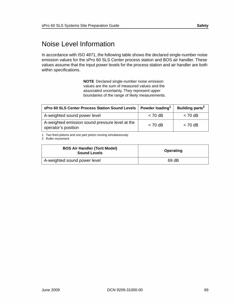
Noise Level InformationIn accordance with ISO 4871, the following table shows the declared single-number noise emission values for the sPro 60 SLS Center process station and BOS air handler. These values assume that the input power levels for the process station and air handler are both within specifications.
NOTE Declared single-number noise emission values are the sum of measured values and the associated uncertainty. They represent upper boundaries of the range of likely measurements.
sPro 60 SLS Center Process Station Sound Levels Powder loading1
1. Two feed pistons and one part piston moving simultaneously
Building parts2
2. Roller movement
A-weighted sound power level < 70 dB < 70 dBA-weighted emission sound pressure level at the operator’s position < 70 dB < 70 dB
BOS Air Handler (Torit Model) Sound Levels Operating
A-weighted sound power level 69 dB
June 2009 DCN 9209-31000-00 69

Safety sPro 60 SLS Systems Site Preparation Guide
Laser Safety Using a laser may cause accidental exposure to radiation. This section discusses safety precautions to guard against exposure during sPro 60 SLS Center operation.
Laser ClassesThe sPro 60 SLS Center contains a 30W or 70 W CO2 continuous-wave laser. The sPro 60 SLS Center is a Class 1 laser product that complies with the Federal Laser Product Performance Standard.
Laser Precautions3D Systems recommends the following laser safety precautions:
All operators should attend a training class for the sPro 60 SLS Center.Only fully qualified and experienced 3D Systems personnel trained in laser safety may perform service procedures.Anyone in the controlled area during service must wear the appropriate safety glasses.When service is in progress, warning signs must be posted.Operators must follow all other safety procedures outlined in the sPro 60 SLS Centers User's Guide (DCN 8002-00001).
Class Explanation1
1. Information taken from the American National Standard Z136.1-2000
Class 1
Any laser, or laser system containing a laser, that cannot emit accessible laser radiation levels in excess of the Class Accessible Emissions Limit (AEL) for the maximum possible duration inherent in the design or intended use of the laser or laser system. For the CO2 laser the AEL is ≤ 9.6 x 10⁻³.
Class 4Ultraviolet and infrared lasers and laser systems which emit an average accessible radiant power in excess of 0.5 W for periods ≤ 0.25 s or produce a radiant energy > 0.125 J within an exposure time of < 0.25 s.
70 DCN 9209-31000-00 3D Systems Corporation
sPro 60 SLS Systems Site Preparation Guide Safety
3D Systems Laser Service ProceduresThis section discusses safety precautions that protect you from accidental radiation exposure while servicing the sPro 60 SLS Center.
Laser Service ProceduresWhen 3D Systems personnel service the laser, they use the following standards and any state and local safety regulations that are appropriate for your facility.
During normal operation or maintenance, an operator must not override interlocks and expose the laser beam outside the cover containment. However, certified service personnel will occasionally need to perform alignment or focus adjustments that will put the laser in a Class 4 circumstance. When this occurs, certified service personnel will follow the procedures outlined below:
The area, called the Nominal Hazard Zone (NHZ), must be secured such that entry is limited, and exiting is in no way restricted. If you place the sPro 60 SLS Center in an area that cannot be secured, your company must provide laser safety curtains. (See “Laser Safety Curtains or Partitions” on page 9.)
Notice signs that say Laser Service In Progress—Eye Protection Required are to be placed at each entrance to the room.All personnel in the area must be notified that laser service procedures will be performed and instructed to wear safety glasses (ANSI Z87; DIN 58215/01.86 and DIN 58219/02.86). The CO2 laser wavelength does not travel through glass and will create a visible indication on polycarbonate; therefore, industrial safety glasses (either glass or polycarbonate) provide adequate eye protection. Your company must provide safety glasses for personnel.
If your company’s safety requirements are more extensive (for example, a red light turned on during laser servicing), you must provide the additional equipment. Certified service personnel will comply with all customer safety requirements.
US and Japan: ANSI Z136.1-2000 section 4.3.1.1Germany: tDIN VDE 0837/02.86 + A1/07.90
June 2009 DCN 9209-31000-00 71

Safety sPro 60 SLS Systems Site Preparation Guide
Powder SafetyThis section discusses procedures you must follow to prevent a safety hazard when using fine powders. All powders provided by 3D Systems are generally safe during normal operations and when used in accordance with the procedures described in the MSDS for each material. 3D Systems supplies the MSDS’s with each material ordered. Additional MSDS’s are available from 3D Systems Customer Support.
The primary safety concerns with SLS powder materials are the potential for a dust explosion and the inhalation of the powders.
Powder Hazards Any airborne dust or fine powder (such as flour or grain dust) can become explosive when ignited under the right conditions.The SLS powders are considered nuisance dust and may cause irritation to the respiratory tract.Skin contact with the powders can cause irritation to the skin (dermatitis); an allergic reaction, a rash or excessively dry skin. Spilled powder can cause the floor to become slippery.
Safe Powder Handling Read the appropriate MSDS before handling any powder.
When handling powder, you should observe the following general precautions:
1. Avoid the dispersion of dust into the air and dust accumulation to minimize the potential for explosions and inhalation. Follow good industrial hygiene practices and exercise care when dumping bags, sweeping, mixing or doing other task which might create dust.
2. Avoid or remove all ignition sources (flames, electrical and/or static sparks).
3. Work in a well-ventilated area to avoid breathing the powdered materials. In normal operations, dust mask (respirators) are not required when handling SLS powder materials. “Normal operations” mean operations in an environment where the dust and particulates in the air do not exceed accepted standards (refer to the MSDS). For conditions where exposure to dust is apparent, a NIOSH approved respirator (type N95 particulate) should be worn.
4. Avoid contact with eyes, skin, and clothing.
72 DCN 9209-31000-00 3D Systems Corporation
sPro 60 SLS Systems Site Preparation Guide Safety
5. Clean up powder spills immediately. Vacuum the dry powder with internally and externally explosion-proof vacuum equipment or wet mop.
Practice good industrial housekeeping and ventilation procedures to minimize powder safety hazards.
Breakout Station (BOS) VentilationWhen using the BOS, follow standard industrial ventilation practices such as those recommended by the American Conference of Governmental Hygienists, Committee on Industrial Ventilation.
Powder StorageProtect 3D Systems powders from open flames and sparks and keep portable heating devices a safe distance away. Store flammable liquids away from all powdered materials.
For additional powder safety information, refer to:
NFPA 654: Standard for the Prevention of Dust Explosions in the Plastics Industry, published by the National Fire Protection Association (Volume 5 of the National Fire Code). This is available from the Superintendent of Documents, Government Printing Office, Washington, D.C. 20402. Tel: +1-202-783-3238.DIN EN 26184 Teil 1/06.91
June 2009 DCN 9209-31000-00 73

Safety sPro 60 SLS Systems Site Preparation Guide
Electrical SafetyElectrical shock is a danger when using or servicing an electric machine. This section explains how to protect yourself from this danger when using or servicing the sPro 60 SLS Center.
During normal operation of the sPro 60 SLS Center, the operator is not exposed to electrical shock hazards.
To protect yourself from electrical shock, see the safety guidelines in the sPro 60 SLS Centers User's Guide (DCN 8002-00001) and follow any local and departmental electrical safety procedures.
Nitrogen/Oxygen SafetyUsing nitrogen causes a threat of oxygen displacement. This section explains oxygen displacement and how to ensure that the sPro 60 SLS Center does not pose a hazard.
To eliminate the possibility of powder combustion during the sintering process, the sPro 60 SLS Center uses nitrogen to make the atmosphere of the process chamber inert. Displacement of the oxygen in a room is possible if excessive nitrogen leaks into the room from the process chamber or nitrogen lines.
To address this possibility, an external machine shutdown signal port is located on the sPro 60 SLS Center. This port enables installation of a room oxygen monitor that automatically implements a shutdown sequence when oxygen levels in the room trigger the alarm.
!WARNING
During some service and maintenance procedures—and during a power loss—the sPro 60 SLS Center can potentially cause an electrical shock even if the high voltage panel is turned off. This danger exists because the sPro 60 SLS Center may contain an optional battery-powered uninterruptible power supply.
74 DCN 9209-31000-00 3D Systems Corporation
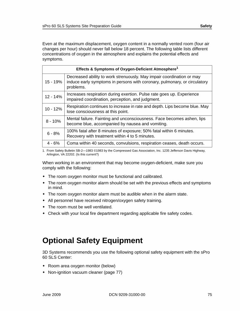
sPro 60 SLS Systems Site Preparation Guide Safety
Even at the maximum displacement, oxygen content in a normally vented room (four air changes per hour) should never fall below 18 percent. The following table lists different concentrations of oxygen in the atmosphere and explains the potential effects and symptoms.
When working in an environment that may become oxygen-deficient, make sure you comply with the following:
The room oxygen monitor must be functional and calibrated.The room oxygen monitor alarm should be set with the previous effects and symptoms in mind.The room oxygen monitor alarm must be audible when in the alarm state.All personnel have received nitrogen/oxygen safety training.The room must be well ventilated.Check with your local fire department regarding applicable fire safety codes.
Optional Safety Equipment3D Systems recommends you use the following optional safety equipment with the sPro 60 SLS Center:
Room area oxygen monitor (below)Non-ignition vacuum cleaner (page 77)
Effects & Symptoms of Oxygen-Deficient Atmosphere1
1. From Safety Bulletin SB-2—1983 ©1983 by the Compressed Gas Association, Inc. 1235 Jefferson Davis Highway, Arlington, VA 22202. (Is this current?)
15 - 19%Decreased ability to work strenuously. May impair coordination or may induce early symptoms in persons with coronary, pulmonary, or circulatory problems.
12 - 14% Increases respiration during exertion. Pulse rate goes up. Experience impaired coordination, perception, and judgment.
10 - 12% Respiration continues to increase in rate and depth. Lips become blue. May lose consciousness at this point.
8 - 10% Mental failure. Fainting and unconsciousness. Face becomes ashen, lips become blue, accompanied by nausea and vomiting.
6 - 8% 100% fatal after 8 minutes of exposure; 50% fatal within 6 minutes. Recovery with treatment within 4 to 5 minutes.
4 - 6% Coma within 40 seconds, convulsions, respiration ceases, death occurs.
June 2009 DCN 9209-31000-00 75
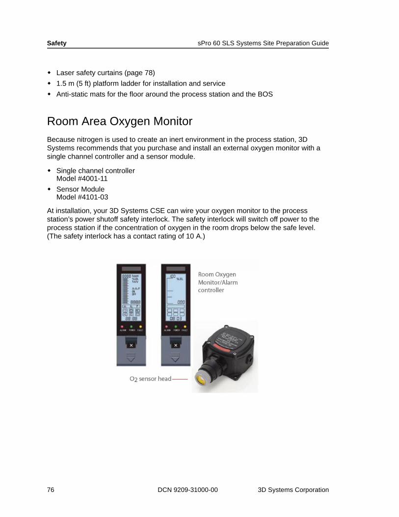
Safety sPro 60 SLS Systems Site Preparation Guide
Laser safety curtains (page 78)1.5 m (5 ft) platform ladder for installation and service Anti-static mats for the floor around the process station and the BOS
Room Area Oxygen MonitorBecause nitrogen is used to create an inert environment in the process station, 3D Systems recommends that you purchase and install an external oxygen monitor with a single channel controller and a sensor module.
Single channel controllerModel #4001-11Sensor ModuleModel #4101-03
At installation, your 3D Systems CSE can wire your oxygen monitor to the process station’s power shutoff safety interlock. The safety interlock will switch off power to the process station if the concentration of oxygen in the room drops below the safe level. (The safety interlock has a contact rating of 10 A.)
76 DCN 9209-31000-00 3D Systems Corporation

sPro 60 SLS Systems Site Preparation Guide Safety
Non-ignition Vacuum Cleaner3D Systems strongly recommends you use a non-ignition vacuum cleaner to clean powder from the sPro 60 SLS Center, part finishing equipment, and the surrounding area. A “non-ignition” model is required due to the potential combustibility of airborne powder.
Non-ignition Vacuum Purchasing Information
Vacuum SafetyObserve the following vacuum safety guidelines:
Hard-wire the vacuum to the power source (no plug). Connect the vacuum to the correct power source. For the standard model, C-83905-01-DTM, the source must be 115 VAC, single phase, 60 Hz.
3D Sys. Part Number 4100-03730 (U.S. and Asia Pacific only)3D Sys. Stocked Item Yes
Specifications/Requirements
DimensionsHeight: 91 cm (36 in)Diameter: 51 cm (20 in)
Weight 32 kg (70 lb)
Facility power 115 VAC, single phase, 60 Hz, 1550 W
Tank size 57 L (15 gal)
Air flow 3.3 m3/min (115 cfm)
Features
38 mm x 254 mm (1.5 in x 10 in) grounded plastic hose38 mm x 432 mm (1.5 in x 17 in) machinery cleaning nozzleFilter protectors (package of 12)Vacuum bags (package of 10)
Warranty Information One year
!WARNING
To avoid shock, the vacuum cleaner should be an internally and externally non-ignition unit with conductive housing, hose, and filter. It should be connected to the same earth ground point as the sPro 60 SLS Center.
Non-ignition vacuum cleaner
June 2009 DCN 9209-31000-00 77

Safety sPro 60 SLS Systems Site Preparation Guide
Laser Safety Curtains or PartitionsLaser safety curtains or partitions (fixed or on rollers) help prevent accidental exposure to radiation when servicing the process station.
If the sPro 60 SLS Center is in an area that cannot be secured during laser calibration, install laser safety curtains or partitions.
NOTE If the area cannot be secured, laser safety curtains or partitions must be in place before 3D Systems performs laser maintenance.
Laser Safety Curtains or Partitions Purchasing Information3D Systems Stocked Item No
Supplier KENTEK Corporation
Phone1-800-432-2323 (U.S.)+1-603-435-5580 (outside U.S.)
Fax +1-603-435-7441Address 19 Depot Street, Pittsfield, NH 03263, USAInternet Address www.kentek-laser.com
Example laser safety curtains and partitions
78 DCN 9209-31000-00 3D Systems Corporation

Contacting 3D Systems
For Customer SupportU.S.: +1 800-999-5553
Europe: +49 6151 357 452
Asia Pacific: +65 430-6681
About this Manual3D Systems strives to constantly improve the sPro 60 SLS Center and this guide. Your corrections and suggestions concerning this document should be addressed to:
3D Systems Inc.Technical Publications333 Three D Systems CircleRock Hill, SC 29730
Revision History DCN 8002-20001: sPro 60 SLS Centers Site Preparation Guide
Revision Release Date Comments
000 June 2009 Initial release
June 2009 DCN 9209-31000-00 79

Legal Notices
Copyright and ImprovementsThis document is copyrighted and contains proprietary information that is the property of 3D SYSTEMS CORPORATION (“3D”). The licensed user, in the name of whom this document is registered (the “Licensed User”) does not have the right to copy, reproduce, or translate this document in any way or to any media without the prior written consent of 3D. No copies of the document may be sold or given to any person or other entity.
3D may (but shall not be obligated to) make improvements to this document from time to time. However, the Licensed User acknowledges that at any time after the expiration of the date of issuance, 3D may institute a periodic charge or fee payable by the Licensed User in return for ongoing receipt of improvements. It is the responsibility of the Licensed User to provide 3D with current information as to its name and address. The Licensed User also undertakes to notify 3D promptly in the event that it considers any of the data contained in this document to be incomplete or erroneous in any respect, in connection with Licensed User's particular use or generally.
FCC NoticeThis equipment has been tested and found to comply with the limits for a class A digital device, pursuant to Part 15 of the FCC Rules. These limits are designed to provide reasonable protection against harmful interference when the equipment is operated in a commercial environment. This equipment generates, uses, and can radiate radio frequency energy and, if not installed and used in accordance with the instruction manual, may cause harmful interference to radio communications. Operation of this equipment in a residential area is likely to cause harmful interference in which case the user will be required to correct the interference at his own expense.
Changes or modifications not expressly approved by 3D Systems Corporation could void your authority to operate this equipment.
June 2009 DCN 9209-31000-00 80
Limitations of Warranty and LiabilityThis information is provided by 3D for the convenience of its customers. It is believed to be reliable, but NO REPRESENTATIONS, GUARANTEES OR WARRANTIES OF ANY KIND ARE MADE AS TO ITS ACCURACY, FITNESS FOR A PARTICULAR USE OR THE RESULTS TO BE OBTAINED THEREFROM. The information is based in whole or in large part on laboratory work and does not necessarily indicate performance in all conditions. Notwithstanding any information provided by 3D or its affiliates, the customer remains fully responsible for determining which federal, state or local laws or regulations, or industry practices are relevant to activities in which it engages, as well as assuring that those laws, regulations or standards are complied with under actual operating conditions, and 3D undertakes no responsibility in these areas.
IN NO EVENT WILL 3D BE RESPONSIBLE FOR DAMAGES OF ANY NATURE, INCLUDING SPECIAL OR CONSEQUENTIAL DAMAGES, RESULTING FROM THE USE OF OR RELIANCE UPON THIS INFORMATION. THE CUSTOMER ASSUMES ALL RISK RESULTING FROM THE USE OF THIS INFORMATION. Customers use of the materials that follow is an acknowledgment of its agreement to the foregoing. Any customer not wishing to be bound should return this material to 3D. Nothing contained herein is to be considered as permission, recommendation, nor as an inducement to practice any patented invention without permission of the patent owner.
Trademarks and Registered Trademarks3D Systems is a trademark of 3D Systems Corporation
3M and DowFrost are trademarks of 3M Corporation
June 2009 DCN 9209-31000-00 81
Legal Notices sPro 60 SLS Center Site Preparation Guide
82 DCN 9209-31000-00 3D Systems Corporation


![DuraForm HST Composite - Rapid Application Group€¦ · HST Composite was processed on a Sinterstation® HiQ™ + HS SLS System at 25 watts laser power, 10 m/sec [400 inches/sec]](https://img.dokumen.tips/doc/110x75/605bed6b4f047e24b0339c0a/duraform-hst-composite-rapid-application-group-hst-composite-was-processed-on.jpg)