Embed Size (px)
DESCRIPTION
Sinowon 3D video measuring machine, both can do contact and non contact measurement, also with 6 models by different travel of X-Y table.
Citation preview

Instruction Manual
3D Video Measuring Machine
VIDEO MEASURING SYSTEM
POWER
OFF
CONTOUK
OFF
SUREACE
OFF
DONGGUAN JATEN PRECISION INSTRUMENT CO . ,LTD .
3D Video Measuring Machine Instruction Manual
1.
2. Attention of delivery and preservation.................................2
3. Instrument working theory.................................................3
4. Uncover and installation...................................................6
5. Measurement method.......................................................7
6. Instrument maintenance..................................................8
7. Instrument consistency.....................................................9
8. Instrument malfunction and dispose.................................10
Safe use and warning........................................................2

3D Video Measuring Machine Instruction Manual
1. When moving instrument, disconnected all the supply power, against hot plug.
2. Handle with care when transportation, all the instrument put in the original package, place
according to the iconic instruction, carry the goods in the way of closed type.
3. Package material must put in the place the children out of reach
Safety instruction
This mark is glued at the places of high temperature and risky, such as cover, shell, lampshade
and so on.
This mark is glued at the places of electricity, signal cable gathered and electrical motor.
! ※
※
2
Attention of delivery and preservation
1. When moving instrument, please power off , i t is prohibited moving the instrument with
electricity.
2. Deliver the instrument carefully to prevent the instrument damage.
It should be put in the original case, obey packing process and adopt sealed packing for
delivery.
3. Put the packing material safely and keeps it away from children to avoid danger.

3D Video Measuring Machine Instruction Manual
Instrument working theory
3
At present, the optic-electricity video measurement technology is one of an advanced and efficient
measuring method; the fig 1 shows its work theory as follow:
Measured work-pieces (placed on work-stage) is illuminated by LED surface light (5) or contour
light (under glass-stage), it has an image via zoom lens (15) and color CCD camera (inside mantle 16),
then produce the image on the PC monitor, it is benchmark measuring that video-reticle is caused
by measuring software, the reticle collimates and measures the work-prices, and movement of
work-stage (13) drives the movement of X,Y-axis linear scales (7 and 14), the linear scales give
birth to analog signals to computer via DRO-board ( produce digital signals), the measuring
software in computer process the data to finish the measuring work.
Video measuring system is made from three key parts:
1) Main body: includes as follows:
Instrument base (10); Pillar (3); Z-axis moving system (2); X, Y work-stage (13) and X, Y drive
stick system (6 and 12).
2) Video System: include as follows:
Zoom lens (15): 0.7X-4.5X, and total magnifications is 30X-230X.
Color CCD camera (inside mantle 16) get the image from Zoom lens, has a image of measured
work-piece and change the video to digital signals, then it transfer the signals to computer color
monitor via S-port.
Color display gives birth to the reticle with edge founder function. Contour light and surface light
has took use of the LED lamp-house, the LED lightness can be adjusted by switch (Fig 3) and the
illumination is better, and LED longevity is 10 times than average bulbs.
3) Digital measuring system, include as follows:
X-axis(14) Y-axis(7) and Z-axis (1) linear scale produce the displacement signals by geometry
movement of work-stage, the signal is collected by measuring software via signal capture card,
and the measuring software show and process the data on the PC.

3D Video Measuring Machine Instruction Manual
Z-axis linear scale 2.Z-axis drive system 3.Pillar 4.Probe
5.Surface illumination group 6.X-axis drive system 7.Y-axis linear scale
8.handspike 9.Base screw 10.Instrument base
11.Operation panel 12.Y-axis drive system 13.Work-stage
14.X-axis linear scale 15.Zoom lens 16.Color CCD camera
1.
Fig. 1
4
POWER CONTOUR
OFF
OFF OFF
SURFACE
1 2 3
Video measuring system
3D Video Measuring Machine Instruction Manual
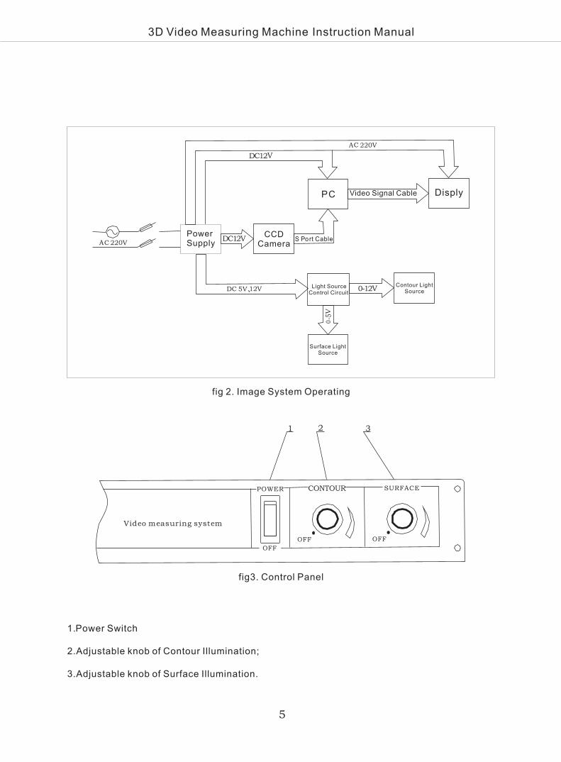
fig 2. Image System Operating
AC 220V
VDC12
AC 220V
PC Video Signal Cable
DC12V
0-12V
0
- 5V
DC 5V 12V、
Disply
Surface Light Source
Power Supply
CCD Camera
S Port Cable
Light Source Control Circuit
Contour Light Source
fig3. Control Panel
1. Switch
2.Adjustable knob of Contour Illumination;
3.Adjustable knob of Surface Illumination.
Power
5

3D Video Measuring Machine Instruction Manual
6
1. Remove the outside and inside package of instrument, take and read this part for installing
instrument firstly.
2. Place the instrument on a horizontal table, install the base screw and adjust it levelly.
3. Take out the fixed ban of X, Y-axis and glide fixed screw of Z-axis (it is on the mantle), then
X, Y, Z-axis can be droved.
Instrument can work under power supply AC110V-220V, 50-60HZ, after connecting the computer,
turn on the instrument power, i f the image and data can be displayed on the monitor, the
installation is finished.
4. Read the operation manual carefully before using.
5. Normally, the authorized distributors wil l install and check the instrument before the end
customers use it.
Uncover and insallation

3D Video Measuring Machine Instruction Manual
7
Measuring
Video measuring system has three kinds of measuring methods: the measurement of profile,
and Z -axis measurement. Please read the Software Manual for details.
1. Profile measurement:
Measuring the profile of work-prices, normally, using the contour illumination, if need, please
turn off the surface light source, which will be assistant to improve the clear of image.
2. Surface measurement:
Surface measurement is main function of video measuring system, it nearly can measure all
of the work-pieces under the surface illumination if it can be saw by eye. Such as the pole of
PCB, IC circuit and so on, and it also can measure the black rubber and plastic easily.
3. Probe measurement:
When match with high multiply objective and with enough collimation and location precision,
video measuring system can use Probe to measure, such as measure the height of work piece,
depth, and so on.

3D Video Measuring Machine Instruction Manual
8
Video measur ing system is a precis ion instrument that integrat ing the opt ic, mechanism,
electr ic i ty and computer technology. In order to keep the excel lent performance, i t needs
regular and upstanding maintenance.
1. The instrument should be instal led in a clean room, the temperature of which should be
maintained at 20°± 5℃ . The relative humidity of the room should not exceed 60﹪ so as to
prevent the molding of optical parts, the rust of metallic parts and the dust drops on the drive
guider to keep the high quality.
2. Once the instrument has been finished using, the surface of work-stage should be cleaned
in soft brushes and covered by dust cover.
3 . The dr ive and movement sys tem should be regu lar ly appended the lube to make the
mechanism movement smooth to keep good using condition.
4. If it is dirty that the glass-stage and paint-surface, it can be cleaned by neutral freshener or
clean water, please don’t use organic solvent to brush, or else, the paint-surface will lose the
reflet.
5 . LED lamp-house has long longev i ty ; p lease in form the d is t r ibu tor and pro fess iona l
engineers instead it if it is bad.
6. The precision parts of instrument, such as video system, work-stage, linear scale and Z-axis
drive system have been precision adjusted in the factory, adjust screws and fixation screws
are riveted in the factory, don’t unbendingly take it out. If there are some problems, please
get in touch with the distributor for after sales.
7. The error compensation of measuring software has been enacted; please don’t change it,
or else, it will give rise t to inaccurate measuring results.
8. Don’t unbendingly take out the electric connectors, if it has already been took, please plug
it into the right port, or else, there is possibility to make the instrument bad.
Instrument maintenance

3D Video Measuring Machine Instruction Manual
9
Fuse
2. Optional Accessories:
Optional accessories
Foot Switch ST 150
Sony CCD Camera
Working Cupboard ST 03
Navitar Zoom Lens
Instrument consistency
1. Standard delivery:
6
7
8
9
10
11
12
13
14
15
16
17
1
2
3
4
5
No. Standard delivery Quantity
Main body 1 SET
Measuring Software QM3.0 1 SET
CCD camera 1 SET
0.7-4.5x zoom lens 1 SET
Calibration Block 1 SET
1
2
3
4
No. Quantity
1 SET
1 SET
1 SET
1 SET
Image and signal capture card 7130 1 SET
LED Light source 1 SET
Renishaw probe MCP K1 1 SET
Anti-dust cover 1 SET
Scale Transfer U3 1 SET
Length Block SGR-100 1 SET
DELL Computer 1 SET
Power cable 1 SET
Instrument operation manual 1COPY
Warranty certificate 1COPY
Quality certificate 1COPY
1EA

3D Video Measuring Machine Instruction Manual
10
※ Malfunction 1: Software can not read data
Analysis: Setting problem of software
Solut ion: Start software----system sett ing---port----RS232---password ( input 123)----
protocol (BCD)----- baud rate—input 9600-enter
(If the above solution can not solute the malfunction, please contact with the Authorized solo
agent)
※ Malfunction 2: No image on monitor
Analysis: COM-interface data setting wrong
Solution: start software---video processing---image source setting—input password (123)-
enter
(If the above solution can not solute the malfunction, please contact with the Authorized solo
agent)
Instrument malfunction and dispose