Embed Size (px)
DESCRIPTION
SSBSC
Citation preview

Single Sideband Suppressed Carrier(J3E)
Single Sideband Suppressed CarrieroGeneration of SSBoModulation indexoDegree of modulationoSpectrum bandwidthoPower voltage and Current calculations
What is Single Sideband Suppressed Carrier?• SSBSC is the form of single
sideband modulation that is most widely used for communications applications on the HF portion of the radio spectrum.
• A form of amplitude modulation in which the carrier is totally suppressed and one of the sidebands is removed
What is Single Sideband Suppressed Carrier?• The SSBSC requires half as much
bandwidth as the conventional double sideband AM and less transmitted power
• Having no carrier, this needs to be re-inserted within the receiver. Any slight differences in carrier re-insertion frequency give rise to changes in pitch of the audio. However it gives the most efficient spectrum and power usage of any single sideband modulation format.
J3F (Meaning)J - Single-sideband, suppressed carrier,3 - a single channel containing analogue informationF - Television (video)
Generation of ssb1. Phase discrimination method or phase shift method
- This method includes two balanced modulators and two phase shifting networks and avoids the use of filters. Both the balanced modulators produce side band as an output.

GenerationIt uses two balanced modulators instead of one. The balanced modulators effectively eliminate the carrier. The carrier oscillator is applied directly to the upper balanced modulator along with the audio modulating signal. Then both the carrier and modulating signal are shifted in phase by 90 degrees and applied to the second lower, balanced modulator. The two balanced modulator output are then added together algebraically.
Phase Shift
Generation of ssb2. filter method
- This can be achieved using one of two methods. The first uses two filters that have different passband center frequencies for USB and LSB respectively. The second uses only one filter but switches different carrier frequencies tuned to pass the USB or LSB to pass through the filter.
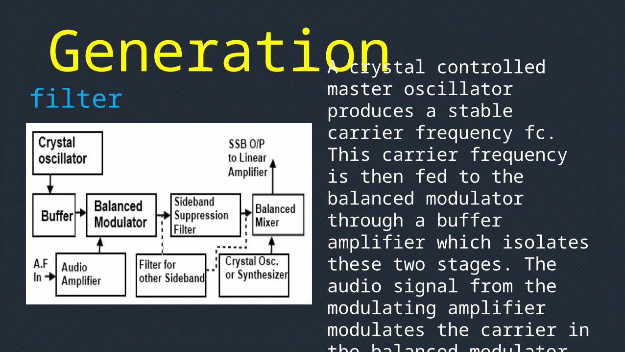
GenerationA crystal controlled master oscillator produces a stable carrier frequency fc. This carrier frequency is then fed to the balanced modulator through a buffer amplifier which isolates these two stages. The audio signal from the modulating amplifier modulates the carrier in the balanced modulator. A bandpass filter allows only a single sideband either a USB or LSB to pass through it. This sideband is then heterodyned in the balanced mixer stage. Then the band is amplified in driver and power amplifier stages and then fed to the aerial for the transmission.
filter

Frequency Spectrum and relative power distribution
Sideband power is makes up to 100% of the total transmitted power
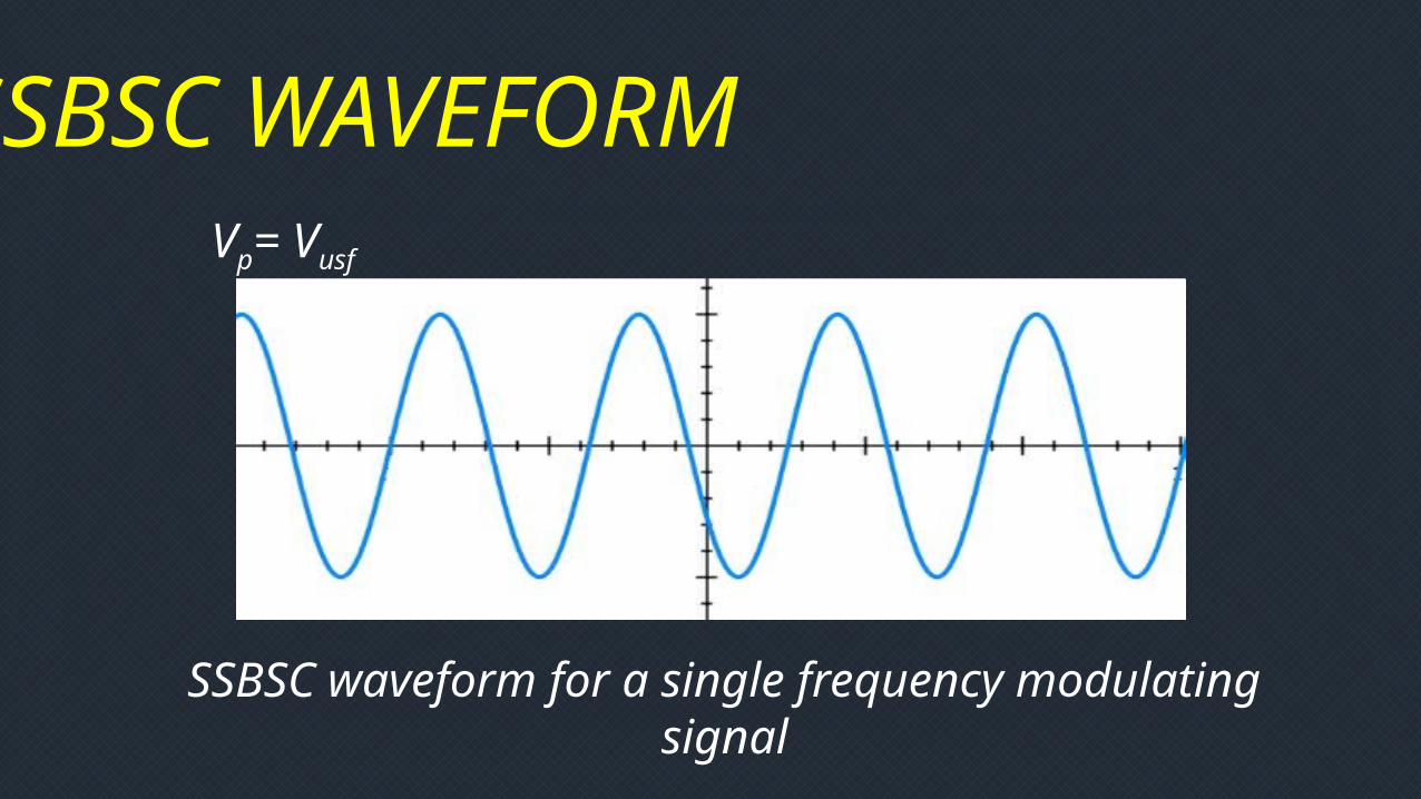
SSBSC WAVEFORM
SSBSC waveform for a single frequency modulating signal
Vp= Vusf

Power Spectrum of SSBC

Power Spectrum of SSBCo The sideband power
calculates 100% of the total power.
o Requires less total power than the conventional AM.
o At 100% modulation, 83.3% of power is saved by suppressing the carrier and one of the sidebands.
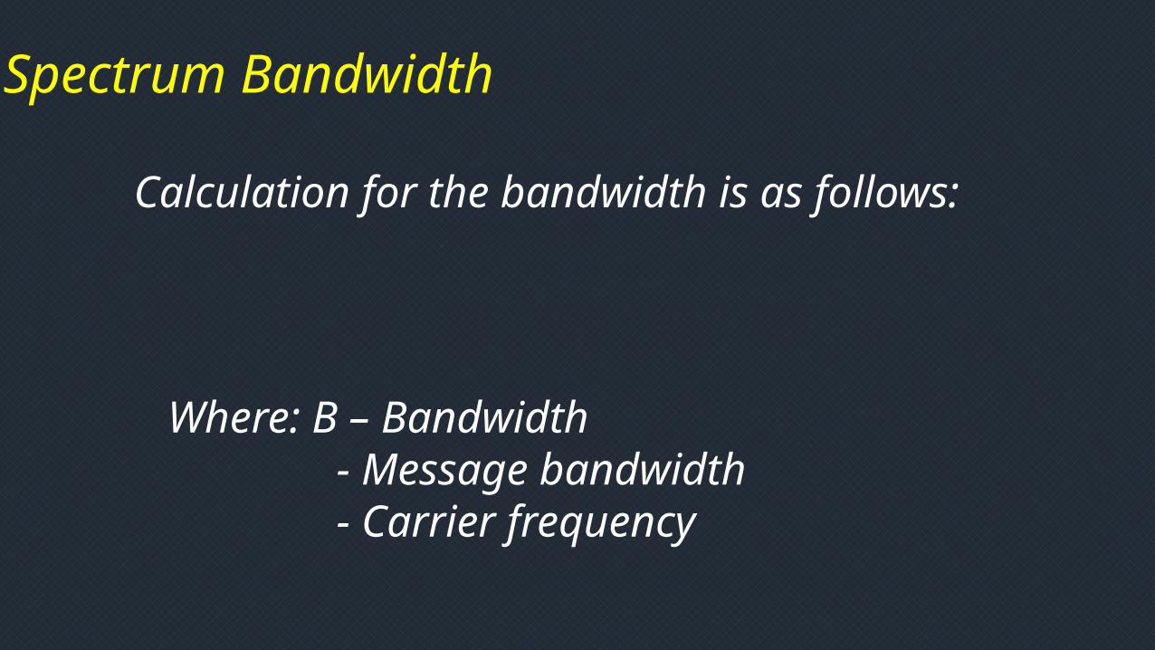
Spectrum Bandwidth
Calculation for the bandwidth is as follows:
Where: B – Bandwidth - Message bandwidth - Carrier frequency
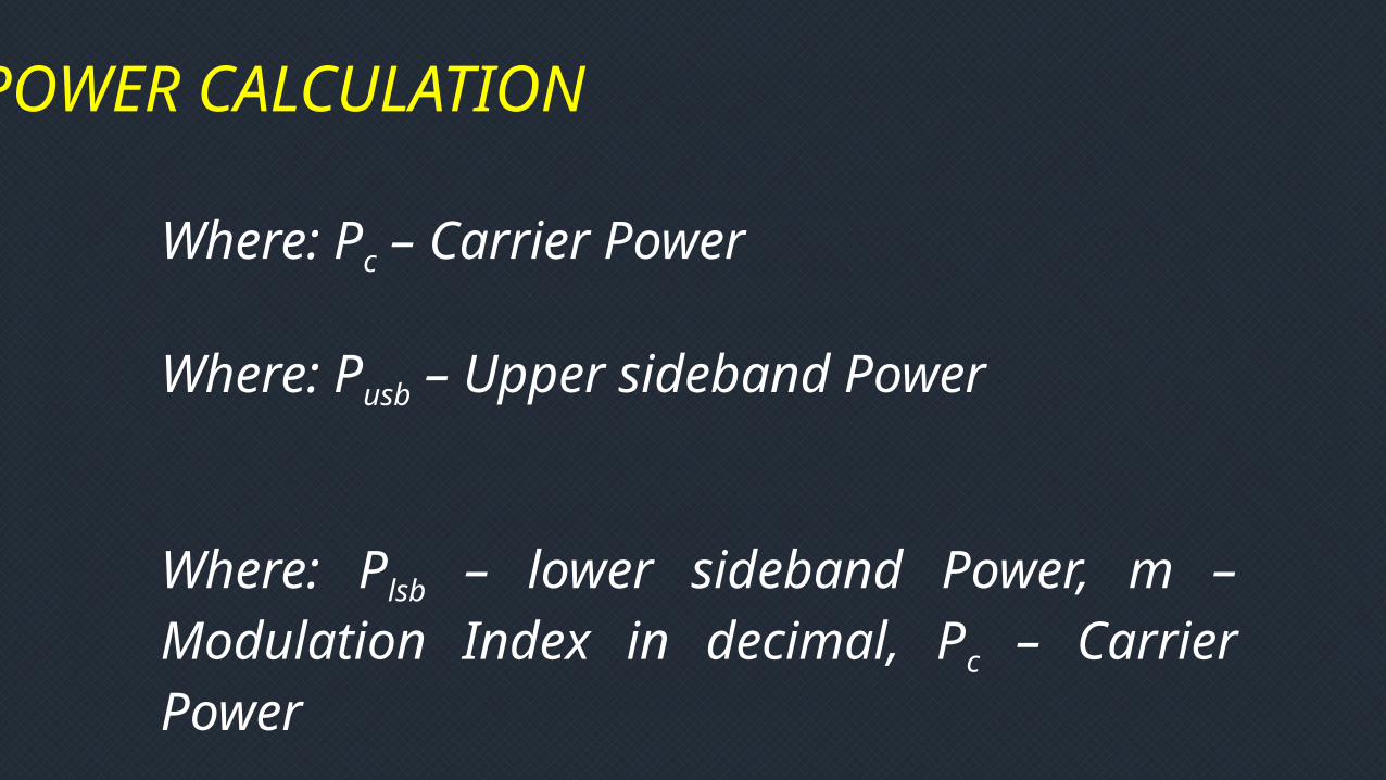
POWER CALCULATION
Where: Pc – Carrier Power
Where: Pusb – Upper sideband Power
Where: Plsb – lower sideband Power, m – Modulation Index in decimal, Pc – Carrier Power
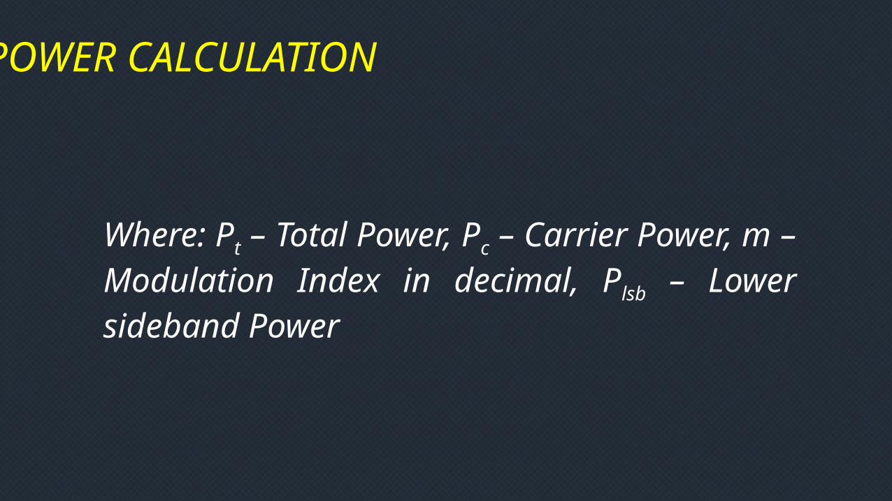
POWER CALCULATION
Where: Pt – Total Power, Pc – Carrier Power, m – Modulation Index in decimal, Plsb – Lower sideband Power

Sample Problem 1:
For a 500W carrier modulated to a depth of 80%, find the total power and the % PS

SOLUTION
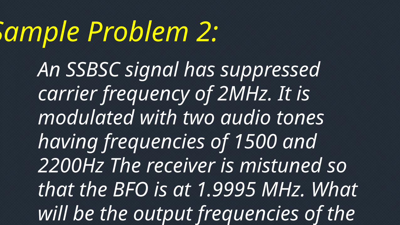
Sample Problem 2:An SSBSC signal has suppressed carrier frequency of 2MHz. It is modulated with two audio tones having frequencies of 1500 and 2200Hz The receiver is mistuned so that the BFO is at 1.9995 MHz. What will be the output frequencies of the demodulator if the signal is LSB?
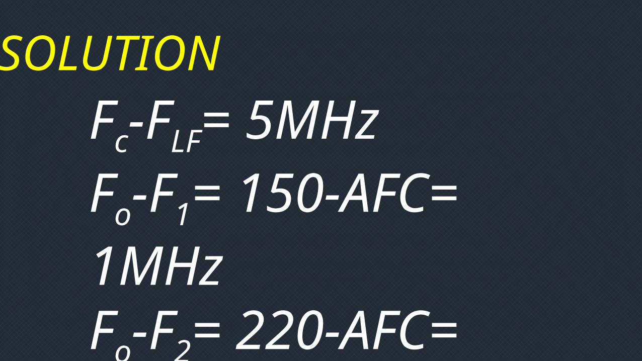
SOLUTIONFc-FLF= 5MHzFo-F1= 150-AFC= 1MHzFo-F2= 220-AFC= 1.715 MHz