Embed Size (px)
Citation preview

Single-ReductionDifferential Carriers
Maintenance Manual 5
Revised 10-06
Standard Carriers Including: Single Axles, Rear of Tandem Axles, Front Drive SteeringAxles
Excluding RS and RT Series (Rear Only),Single-Reduction Axlesand RF Series FrontDrive Axles

Service Notes
Before You Begin
This manual provides instructions for Meritor’s early production non-RF, -RS or -RT Series axles. Before you begin procedures:
1. Read and understand all instructions an procedures before you begin to service components.
2. Read and observe all Caution and Warning safety alerts that precede instructions or procedures you will perform. These alerts help to avoid damage to components, serious personal injury, or both.
3. Follow your company’s maintenance and service, installation, and diagnostics guidelines.
4. Use special tools when required to help avoid serious personal injury and damage to components.
Safety Alerts, Torque Symbol and Notes
Access Information on ArvinMeritor’s Website
Additional maintenance and service information for ArvinMeritor’s commercial vehicle systems component lineup is also available at www.arvinmeritor.com.
To access information, click on Products & Services/Tech Library Icon/HVS Publications. The screen will display an index of publications by type.
Additional Information
For complete maintenance and service procedures for all single-reduction differential carriers, call ArvinMeritor’s Customer Service Center at 800-535-5560 to order the following publications.
� Traction Controls package contains two videos — Splitting the Difference T-87127V and Driver-Controlled Full Locking Main Differential T-9007V. $50. Order T-95125V for this package or each video is available individually as well.
� Technical Electronic Library on CD. Features product and service information on most ArvinMeritor, ZF Meritor and Meritor WABCO components. $20. Order TP-9853.
How to Obtain Tools and Supplies Specified in This Manual
Kiene Diesel Accessories, Inc., 325 S. Fairbanks Street, Addison, IL 60101. Call the company’s customer service center at 800-264-5950, or visit their website at kienediesel.com.
SPX/OTC Service Solutions, 655 Eisenhower Drive, Owatonna, MN 55060. Call the company’s service center at 800-533-6128, or visit their website at otctools.com.
WARNING
A Warning alerts you to an instruction or procedure that you must follow exactly to avoid serious personal injury and damage to components.
CAUTION
A Caution alerts you to an instruction or procedure that you must follow exactly to avoid damage to components and possible serious injury.
T A torque symbol alerts you to tighten fasteners to a specified torque value.
NOTE A Note provides information or suggestions that help you correctly service a component.

Table of Contents
Exploded View . . . . . . . . . . . . . . . . . . . . . . . . . . . . . . . . . . . . . . . . . . . . . . . . . . . . . . . . . . . . . . . . . . . . . . . . . .1
Section 1: Introduction Standard Single-Reduction Carriers . . . . . . . . . . . . . . . . . . . . . . . . . . . . . . . . . . . . . . . . . . . . . . . . . . . . . . .4Axle Models Covered in This Manual . . . . . . . . . . . . . . . . . . . . . . . . . . . . . . . . . . . . . . . . . . . . . . . . . . . . .5
Section 2: Disassembly Axle Shaft Removal Methods . . . . . . . . . . . . . . . . . . . . . . . . . . . . . . . . . . . . . . . . . . . . . . . . . . . . . . . . . . . .6Brass Drift Method Air Hammer Vibration Method Remove Differential Carrier from Axle Housing . . . . . . . . . . . . . . . . . . . . . . . . . . . . . . . . . . . . . . . . . . . . .7Carrier Removal from Axle . . . . . . . . . . . . . . . . . . . . . . . . . . . . . . . . . . . . . . . . . . . . . . . . . . . . . . . . . . . . . .9Remove the Differential and Ring Gear from the Carrier . . . . . . . . . . . . . . . . . . . . . . . . . . . . . . . . . . . . .11Disassemble the Differential and Ring Gear Assembly . . . . . . . . . . . . . . . . . . . . . . . . . . . . . . . . . . . . . .13Remove the Drive Pinion and Bearing Cage from Carrier . . . . . . . . . . . . . . . . . . . . . . . . . . . . . . . . . . . .15Disassemble the Drive Pinion and Bearing Cage . . . . . . . . . . . . . . . . . . . . . . . . . . . . . . . . . . . . . . . . . . .16
Section 3: Preparing the Parts for Assembly Cleaning Ground and Polished Parts . . . . . . . . . . . . . . . . . . . . . . . . . . . . . . . . . . . . . . . . . . . . . . . . . . . . .20Cleaning Rough Parts Cleaning Axle Assemblies Drying Parts After Cleaning Preventing Corrosion on Cleaned Parts . . . . . . . . . . . . . . . . . . . . . . . . . . . . . . . . . . . . . . . . . . . . . . . . . . .21Inspecting Parts Repair or Replacement of Parts, General . . . . . . . . . . . . . . . . . . . . . . . . . . . . . . . . . . . . . . . . . . . . . . . . . .23Repair Axle by Welding . . . . . . . . . . . . . . . . . . . . . . . . . . . . . . . . . . . . . . . . . . . . . . . . . . . . . . . . . . . . . . . .24Bending or Straightening Drive Axle Housings . . . . . . . . . . . . . . . . . . . . . . . . . . . . . . . . . . . . . . . . . . . .25Removing Dri-Loc® Fasteners
Section 4: General Information Installing Fasteners with Pre-Applied Adhesive, Meritor Liquid Adhesive 2297-C-7049,
Loctite® 680 Liquid Adhesive or Equivalent . . . . . . . . . . . . . . . . . . . . . . . . . . . . . . . . . . . . . . . . . . .26Installing New Fasteners with Pre-applied Adhesive Patches Installing Original or Used Fasteners Using Meritor Liquid Adhesive 2297-C-7049 or
Loctite® 680 or Equivalent Application of Meritor Adhesive 2297-T-4180 in Bearing Bores for the Differential Application of Three Bond 1216 or Equivalent Silicone Gasket Material . . . . . . . . . . . . . . . . . . . . . . . .27Installing Tight Fit Yokes and POSE™ Seal . . . . . . . . . . . . . . . . . . . . . . . . . . . . . . . . . . . . . . . . . . . . . . . .28General Yoke and U-Joint Reassembly . . . . . . . . . . . . . . . . . . . . . . . . . . . . . . . . . . . . . . . . . . . . . . . . . . .29Gear Set Information (Drive Pinion and Ring Gear Marks)
Section 5: Assembly Assemble the Drive Pinion, Bearings and Bearing Cage . . . . . . . . . . . . . . . . . . . . . . . . . . . . . . . . . . . . .31Adjusting Preload of Pinion Bearings . . . . . . . . . . . . . . . . . . . . . . . . . . . . . . . . . . . . . . . . . . . . . . . . . . . . .36Adjusting Shim Pack Thickness for the Pinion Cage (Depth of Pinion) . . . . . . . . . . . . . . . . . . . . . . . . . .41Installing the Drive Pinion, Bearing Cage and Shim Pack into the Carrier . . . . . . . . . . . . . . . . . . . . . . .43Installing Tight Fit Yokes and POSE™ Seal . . . . . . . . . . . . . . . . . . . . . . . . . . . . . . . . . . . . . . . . . . . . . . . .44Assemble the Main Differential and Ring Gear Assembly . . . . . . . . . . . . . . . . . . . . . . . . . . . . . . . . . . . .45Inspecting the Rotating Resistance of the Differential Gears . . . . . . . . . . . . . . . . . . . . . . . . . . . . . . . . . .48Install the Differential and Ring Gear Assembly . . . . . . . . . . . . . . . . . . . . . . . . . . . . . . . . . . . . . . . . . . . .49Adjust Preload of Differential Bearings . . . . . . . . . . . . . . . . . . . . . . . . . . . . . . . . . . . . . . . . . . . . . . . . . . .50Method 1 Method 2 . . . . . . . . . . . . . . . . . . . . . . . . . . . . . . . . . . . . . . . . . . . . . . . . . . . . . . . . . . . . . . . . . . . . . . . . . . . .52Inspect Runout of Ring Gear . . . . . . . . . . . . . . . . . . . . . . . . . . . . . . . . . . . . . . . . . . . . . . . . . . . . . . . . . . . .53Ring Gear Backlash Adjustment Inspect Tooth Contact Patterns of the Gear Set . . . . . . . . . . . . . . . . . . . . . . . . . . . . . . . . . . . . . . . . . . . .55Install and Adjust the Thrust Screw . . . . . . . . . . . . . . . . . . . . . . . . . . . . . . . . . . . . . . . . . . . . . . . . . . . . . .60Install Differential Carrier into Axle Housing . . . . . . . . . . . . . . . . . . . . . . . . . . . . . . . . . . . . . . . . . . . . . . .61Straight Holes, Nuts and Hardened Washers . . . . . . . . . . . . . . . . . . . . . . . . . . . . . . . . . . . . . . . . . . . . . .63Tapered Dowel, Hardened Washer and Hardened Nut

Table of Contents
Section 6: Lubrication . . . . . . . . . . . . . . . . . . . . . . . . . . . . . . . . . . . . . . . . . . . . . . . . . . . . . . . . . . . . . . . 64Axle Lubricant Capacities . . . . . . . . . . . . . . . . . . . . . . . . . . . . . . . . . . . . . . . . . . . . . . . . . . . . . . . . . . . . . . 66
Section 7: Fastener Torque Information Torque Values for Fasteners . . . . . . . . . . . . . . . . . . . . . . . . . . . . . . . . . . . . . . . . . . . . . . . . . . . . . . . . . . . 67General Information American Standard FastenersMetric Fasteners
Section 8: Adjustments and Specifications . . . . . . . . . . . . . . . . . . . . . . . . . . . . . . . . . . . . . . . . . . 71
Section 9: Vehicle Towing Instructions (Non-DCDL) Before Towing or Drive-Away . . . . . . . . . . . . . . . . . . . . . . . . . . . . . . . . . . . . . . . . . . . . . . . . . . . . . . . . . . 73After Towing or Drive-Away . . . . . . . . . . . . . . . . . . . . . . . . . . . . . . . . . . . . . . . . . . . . . . . . . . . . . . . . . . . 74

1
Exploded View
Exploded View — Legend
1 Nut — Drive Pinion
2 Washer — Drive Pinion*
3 Input Yoke* or Flange*
4 Deflector
5 Oil Seal
6 Capscrew — Bearing Cage
7 Washer
8 Bearing Cone — Pinion Outer
9 Bearing Cup — Pinion Outer
10 Bearing Cage — Drive Pinion
11 Shims
12 Spacer— Pinion Bearing
13 Bearing Cup — Pinion Inner
14 Bearing Cone — Pinion Inner
15 Drive Pinion
16 Spigot Bearing
16A Snap Ring
17 Carrier
18 Thrust Screw*
19 Jam Nut* — Thrust Screw*
20 Adjusting Ring — L.H.
21 Cotter* or Pin*
22 Caps — Differential Bearing
23 Washers
24 Capscrews — Differential Bearing Cap
25 Lock Plate* — Adjusting Ring
* Some Meritor carriers do not have these described parts.
26 Washers* — Lock Plate
27 Capscrews* — Lock Plate*
28 Adjusting Ring — R.H.
29 Plug* — Oil Fill Hole (carrier)
30 Washer* — Capscrew/Plug*
31 Capscrew/Plug — Sensor Hole
32 Thrust Block*
33 Washers* — Differential Case
34 Nuts* — Differential Case
35 Bearing Cup — Differential L.H.
36 Bearing Cone — Differential L.H.
37 Nuts* — Ring Gear and Case Half
38 Case Half — Flange
39 Ring Gear
40 Bolts* or Rivets* — Ring Gear and
Case Half
41 Side Gears —Differential
42 Thrust Washers — Differential Pinion
43 Pinions — Differential
44 Spider — Differential
45 Thrust Washers — Differential Side
Gear
46 Capscrews — Differential Case
47 Bolts* — Differential Case
48 Bearing Cup — Differential R.H.
49 Bearing Cone — Differential R.H.
50 Case Half — Plain
NoSPIN® is a registered trademark of Tractech, a division of Dyneer Corp.

Exploded View
2
Single-Reduction Differential Carrier

3
Exploded View

Section 1Introduction
4
Section 1Introduction
Standard Single-Reduction Carriers
NOTE: For carriers with a differential lock, refer to Maintenance Manual 5A.
Meritor single-reduction standard carriers, Figure 1.1, are used in most Meritor single axles, rear of tandem axles and front drive steering axles.
The single-reduction carrier models are front mounted into the axle housing. These carriers have a hypoid drive pinion and ring gear set and bevel gears in the differential assembly.
A straight roller bearing (spigot) is mounted on the head of the drive pinion. All other bearings in the carrier are tapered roller bearings.
When the carrier operates, there is normal differential action between the wheels all the time.
Figure 1.1
1 TAPERED ROLLER BEARINGS2 CARRIER3 STRAIGHT ROLLER BEARING4 TAPERED ROLLER BEARING
5 BEVEL DIFFERENTIAL GEARS6 HOUSING7 TAPERED ROLLER BEARING8 HYPOID DRIVE PINION AND RING GEAR

5
Section 1Introduction
Axle Models Covered in This Manual
The following table lists all axle models covered in this manual.
Single Drive Axles:
For All RS & RT
Single-Reduction
Axle Model Series, Refer to
Maintenance
Manual 5A.
A-150 E-100 F-140 H-172 Q-100 R-163
B-100 E-105 G-161 L-100 Q-145 R-170
B-140 E-150 H-100 L-140 RL-170 S-170
B-150 F-100 H-140 L-155 R-100 U-140
C-100 F-106 H-150 L-172 R-140 W-170
D-100 F-120 H-162 M-172 R-155
D-140 F-121 H-170 QT-140 R-160
Rear Axle of Tandem Axles:
SDHD SL-100 SQHD SSHD SU-170
SFHD SLHD SR-170 ST-170 SUHD
SHHD SQ-100 SRHD STHD SW-170
Front Drive Steering Axles:
FDS-75 FDS-85 FDS-93 FDS-1807 FDS-2100 FDS-2107 FDS-2111
FDS-78 FDS-90 FDS-1600 FDS-1808 FDS-2101 FDS-2110 FDS-2117

Section 2Disassembly
6
Section 2Disassembly
Axle Shaft Removal Methods
Meritor Recommends Using Special Tools
To help prevent serious personal injury and damage to components when you remove the axle shaft from the housing, Meritor recommends that you use the tools in the table below. Refer to the Service Notes page at the front inside cover of this manual for information on how to contact the manufacturers to obtain the tools.
� If the tools are not available when you remove the axle shaft: Follow procedures for using the Brass Drift Method or the Air Vibration Method.
Brass Drift Method
WARNINGDo not strike the round driving lugs on the flange of an axle shaft. Pieces can break off and cause serious personal injury.
1. Hold a 1-1/2 -inch diameter brass drift or brass hammer against the center of the axle shaft, inside the round driving lugs. Figure 2.1.
2. Strike the end of the drift with a large hammer, five to six pounds, and the axle shaft and tapered dowels will loosen.
3. Mark each axle shaft before it is removed from the axle assembly.
4. Remove the tapered dowels and separate the axle shafts from the main axle hub assembly. Figure 2.2.
5. Install a cover over the open end of each axle assembly hub where an axle shaft was removed.
Air Hammer Vibration Method
WARNINGWear safe eye protection when using an air hammer. When using power tools, axle components can loosen and break off causing serious personal injury.
CAUTIONDo not use a chisel or wedge to loosen the axle shaft and tapered dowels. Using a chisel or wedge can result in damage to the axle shaft, the gasket and seal, and the axle hub.
1. Use a round hammer bit and an air hammer to loosen the tapered dowels and axle shaft.
2. Place the round hammer bit against the axle shaft or flange between the hub studs. Operate the air hammer at alternate locations between the studs to loosen the tapered dowels and axle shaft from the hub. Figure 2.3.
Tool Part Number Manufacturer
Axle Shaft Remover
K-1280 Kiene Diesel Accessories, Inc.
Axle Stud Cone Plier
7077 SPX OTC
Figure 2.1
Figure 2.2
7
Section 2Disassembly
3. Mark each axle shaft before it is removed from the axle assembly.
4. Remove the tapered dowels and separate the axle shaft from the main axle hub assembly. Figure 2.2.
Remove Differential Carrier from Axle Housing
WARNINGTo prevent serious eye injury, always wear safe eye protection when you perform vehicle maintenance or service.
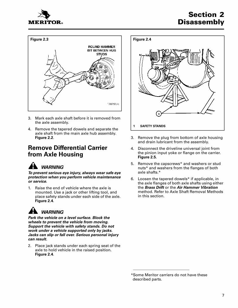
1. Raise the end of vehicle where the axle is mounted. Use a jack or other lifting tool, and place safety stands under each side of the axle. Figure 2.4.
WARNINGPark the vehicle on a level surface. Block the wheels to prevent the vehicle from moving. Support the vehicle with safety stands. Do not work under a vehicle supported only by jacks. Jacks can slip or fall over. Serious personal injury can result.
2. Place jack stands under each spring seat of the axle to hold vehicle in the raised position. Figure 2.4.
3. Remove the plug from bottom of axle housing and drain lubricant from the assembly.
4. Disconnect the driveline universal joint from the pinion input yoke or flange on the carrier. Figure 2.5.
5. Remove the capscrews* and washers or stud nuts* and washers from the flanges of both axle shafts.*
6. Loosen the tapered dowels* if applicable, in the axle flanges of both axle shafts using either the Brass Drift or the Air Hammer Vibration method. Refer to Axle Shaft Removal Methods in this section.
Figure 2.3 Figure 2.4
1 SAFETY STANDS
*Some Meritor carriers do not have these described parts.

Section 2Disassembly
8
Figure 2.5
1 FULL ROUND BEARING CUPS2 END YOKE3 YOKE SADDLE4 WELD YOKE5 BEARING STRAP6 CAPSCREWS7 EASY-SERVICE BEARING CUPS8 U-JOINT CROSS9 SLIP YOKE
10 CAPSCREWS11 END YOKE12 WELD YOKE13 SLIP YOKE14 U-JOINT CROSS15 CAPSCREWS16 END YOKE17 WELD YOKE
18 SLIP YOKE19 U-JOINT CROSS20 CAPSCREWS21 END YOKE22 SLIP YOKE23 TUBING24 U-JOINT CROSS25 WELD YOKE

9
Section 2Disassembly
Carrier Removal from Axle
1. Place a hydraulic roller jack under the differential carrier to support the assembly. Figure 2.6.
2. Remove all but the top two carrier to housing capscrews or stud nuts and washers.
3. Loosen the top two carrier-to-housing fasteners and leave attached to the assembly. The fasteners will hold the carrier in the housing.
4. Loosen the differential carrier in the axle housing. Use a leather mallet to hit the mounting flange of carrier at several points.
5. After the carrier is loosened, remove the top two fasteners.
CAUTIONWhen using a pry bar be careful not to damage the carrier or housing flange. Damage to these surfaces will cause oil leaks.
6. Carefully remove the carrier from the axle housing using the hydraulic roller jack. Use a pry bar that has a round end to help remove the carrier from the housing.
7. Lift the differential carrier by the input yoke or flange and place the assembly in a repair stand. Figure 2.7. Use a lifting tool for this procedure. Do not lift by hand. A carrier stand can be built by referring to Figure 2.8.
Figure 2.6
1 WOOD BLOCK2 ROLLER JACK
Figure 2.7
1 DIFFERENTIAL CARRIER2 REPAIR STAND

Section 2Disassembly
10
A carrier stand, part number J 3409-D is available from Kent-Moore, Heavy-Duty Division, 28635 Mound Road, Warren, MI 48092.
Figure 2.8
1 PLATES 8' LONG x 3/4" THICK x 1-1/4" WIDE WITH A TONGUE TO FIT SLOT IN BAR WELD PLATES TO BAR
2 HANDLE 7" LONG WITH SLOT IN ONE END TO FIT CLAMP SCREW
3 BAR 2" DIAMETER x 9" LONG WITH ONE END SLOTTED TO FIT PLATE
4 WELD ALL AROUND AFTER PRESSING PLUG IN PIPE5 WELD6 SHAPE AND SIZE OF HOLES TO FIT CARRIER
7 23-1/2" CENTER TO CENTER OF PIPE8 CHAMFER END OF PIPE FOR WELDING9 4” DIAMETER PIPE10 PLUG 4" DIAMETER x 7" LONG WITH ONE END TURNED
3" LONG TO FIT PIPE. DRILL 2" HOLE AND MILL 3/16" WIDE SLOT 2" FROM TOP
11 SCREW 3-1/2" LONG x 5/8" DIAMETER WITH FLATS ON END TO FIT HANDLE AND 2-1/2" LENGTH OF THREAD ON OTHER END
12 DRILL 3/8" HOLE THROUGH HANDLE AND SCREW
CARRIER STAND

11
Section 2Disassembly
Remove the Differential and Ring Gear from the Carrier
NOTE: Before working on the differential carrier, inspect the hypoid gear set for damage. If inspection shows no damage, the same gear set can be used again. Measure the backlash of the gear set and make a record of the dimension. Figure 2.9. (Refer to “Ring Gear Backlash Adjustment” in Section 5, Steps 1-5.) During differential reassembly, adjust the backlash to the original recorded dimension when the gear set is installed into the carrier.
1. Loosen the jam nut* on the thrust screw*. Figure 2.10.
2. Remove the thrust screw* and jam nut* from the differential carrier. Figure 2.11.
3. Rotate the differential carrier in the repair stand until the ring gear is at the top of the assembly.
4. Mark one carrier leg and bearing cap to correctly match the parts during carrier assembly. Mark the parts using a center punch and hammer. Figure 2.12.
Figure 2.9
1 DIAL INDICATOR
Figure 2.10
*Some Meritor carriers do not have these described parts.
Figure 2.11
1 THRUST SCREW AND JAM NUT
Figure 2.12
1 BEARING CAP2 CARRIER LEG3 MATCH MARKS

Section 2Disassembly
12
5. Remove the cotter keys*, pins* or lock plates* that hold the two bearing adjusting rings in position. Use a small drift and hammer to remove pins. Each lock plate is held in position by two capscrews. Figure 2.13.
6. Remove the capscrews and washers that hold the two bearing caps on the carrier. Each cap is held in position by two capscrews and washers. Figure 2.14.
7. Remove the bearing caps and bearing adjusting rings from the carrier. Figure 2.15.
8. Safely lift the main differential and ring gear assembly from the carrier. Place the assembly on a work bench. Figure 2.16.
*Some Meritor carriers do not have these described parts.
Figure 2.13
1 REMOVING COTTER KEY2 REMOVING LOCK PLATE
Figure 2.14
1 BEARING CAP
Figure 2.15
1 BEARING CAP2 BEARING ADJUSTING RING
Figure 2.16

13
Section 2Disassembly
Disassemble the Differential and Ring Gear Assembly
1. If the matching marks on the case halves of the differential assembly are not visible, mark each case half with a center punch and hammer. The purpose of the marks is to match the plain half and flange half correctly when you assemble the carrier. Figure 2.17.
2. Remove the capscrews* and washers* or bolts*, nuts* and washers that hold the case halves together.
WARNINGUse a brass or leather mallet for assembly and disassembly procedures. Do not hit steel parts with a steel hammer. Pieces of a part can break off and cause serious personal injury.
3. Separate the case halves. If necessary, use a brass, plastic or leather mallet to loosen the parts.
4. Remove the differential spider (cross), four pinion gears, two side gears and six thrust washers from inside the case halves. Figure 2.18.
5. If the ring gear needs to be replaced, remove the bolts*, nuts*, and washers* that hold the gear to the flange case half.
WARNINGObserve all warnings and cautions provided by the press manufacturer to avoid damage to components and serious personal injury.
CAUTIONDo not remove the rivets or rivet heads with a chisel and hammer. Using a flat edge tool can cause damage to the flange case.
6. If rivets* hold the ring gear to the flange case half, remove the rivets as follows:
7. Carefully center punch each rivet head in the center, on the ring gear side of the assembly.
Figure 2.17
1 MATCH MARKS2 MATCH MARKS
Figure 2.18
1 THRUST WASHER2 SIDE GEAR3 SPIDER, PINIONS AND THRUST WASHERS
*Some Meritor carriers do not have these described parts.
Section 2Disassembly
14
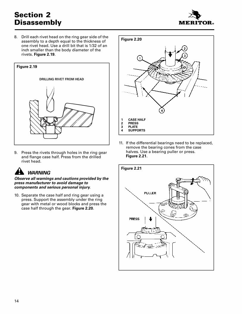
8. Drill each rivet head on the ring gear side of the assembly to a depth equal to the thickness of one rivet head. Use a drill bit that is 1/32 of an inch smaller than the body diameter of the rivets. Figure 2.19.
9. Press the rivets through holes in the ring gear and flange case half. Press from the drilled rivet head.
WARNINGObserve all warnings and cautions provided by the press manufacturer to avoid damage to components and serious personal injury.
10. Separate the case half and ring gear using a press. Support the assembly under the ring gear with metal or wood blocks and press the case half through the gear. Figure 2.20.
11. If the differential bearings need to be replaced, remove the bearing cones from the case halves. Use a bearing puller or press.Figure 2.21.
Figure 2.19
1003001b
DRILLING RIVET FROM HEAD
Figure 2.20
1 CASE HALF2 PRESS3 PLATE4 SUPPORTS
Figure 2.21
15
Section 2Disassembly
Remove the Drive Pinion and Bearing Cage from Carrier
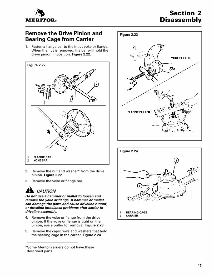
1. Fasten a flange bar to the input yoke or flange. When the nut is removed, the bar will hold the drive pinion in position. Figure 2.22.
2. Remove the nut and washer* from the drive pinion. Figure 2.22.
3. Remove the yoke or flange bar.
CAUTIONDo not use a hammer or mallet to loosen and remove the yoke or flange. A hammer or mallet can damage the parts and cause driveline runout, or driveline imbalance problems after carrier to driveline assembly.
4. Remove the yoke or flange from the drive pinion. If the yoke or flange is tight on the pinion, use a puller for removal. Figure 2.23.
5. Remove the capscrews and washers that hold the bearing cage in the carrier. Figure 2.24.
Figure 2.22
1 FLANGE BAR2 YOKE BAR
*Some Meritor carriers do not have these described parts.
Figure 2.23
Figure 2.24
1 BEARING CAGE2 CARRIER

Section 2Disassembly
16
WARNINGUse a brass or leather mallet for assembly and disassembly procedures. Do not hit steel parts with a steel hammer. Pieces of a part can break off and cause serious personal injury.
CAUTIONDo not use a pry bar to remove the bearing cage from the carrier. A pry bar can damage the bearing cage, shims and carrier.
6. Remove the drive pinion, bearing cage and shims from the carrier. If the bearing cage is tight in the carrier, hit the bearing cage at several points around the flange area with a leather, plastic or rubber mallet. Figure 2.25.
7. If the shims are in good condition, keep the shims together for use later when the carrier is assembled.
8. If shims are to be discarded because of damage, first measure the total thickness of the pack. Make a note of the dimension. The dimension will be needed to calculate the depth of the drive pinion in the carrier when the gear set is installed.
Disassemble the Drive Pinion and Bearing Cage
WARNINGObserve all warnings and cautions provided by the press manufacturer to avoid damage to components and serious personal injury.
1. Place the drive pinion and bearing cage in a press. The pinion shaft must be toward the top of the assembly. Figure 2.27.
Figure 2.25
1 DRIVE PINION AND BEARING CAGE2 SHIMS
Figure 2.26
1 DRIVE PINION2 OIL SEAL3 OUTER BEARING (CUP AND CONE)4 INNER BEARING (CUP AND CONE)5 SPIGOT BEARING6 SNAP RING7 BEARING SPACER

17
Section 2Disassembly
2. Support the bearing cage under the flange area with metal or wood blocks. Figure 2.27.
3. Press the drive pinion through the bearing cage. Figure 2.27.
WARNINGUse a brass or leather mallet for assembly and disassembly procedures. Do not hit steel parts with a steel hammer. Pieces of a part can break off and cause serious personal injury.
NOTE: The inner bearing cone and bearing spacer will remain on the pinion shaft.
4. If a press is not available, use a leather, plastic or rubber mallet to drive the pinion through the bearing cage.
CAUTIONBe careful when removing the seal. Do not damage the wall of bore. Damage to the bore wall can result in oil leaks.
NOTE: When the oil seal has been removed, always replace it with a new triple-lip (main) seal during component reassembly.
5. If the pinion oil seal is mounted directly in the outer bore of the bearing cage, remove the seal at this time.
Be careful that you do not damage the mounting surfaces of the bearing cage. Figure 2.28.
WARNINGObserve all warnings and cautions provided by the press manufacturer to avoid damage to components and serious personal injury.
6. If the pinion bearings need to be replaced, remove the inner and outer bearing cups from the inside of cage. Use a press and sleeve, bearing puller, bearing driver or a small drift hammer. The type of tool used depends on the design of the bearing cage. Figure 2.29.
When a press is used, support the bearing cage under the flange area with metal or wood blocks.
Figure 2.27
1 PRESS2 DRIVE PINION3 OIL SEAL4 BEARING CAGE5 SUPPORT6 SPIGOT BEARING7 SUPPORT
Figure 2.28
1 OIL SEAL
Figure 2.29

Section 2Disassembly
18
7. If the pinion bearings need to be replaced, remove the inner bearing cone from the drive pinion with a press or bearing puller. The puller MUST fit under the inner race of the cone to remove the cone correctly without damage. Figure 2.30.
8. If the spigot bearing needs to be replaced, place the drive pinion in a vise. Install a soft metal cover over each vise jaw to protect the drive pinion.
9. Remove the snap ring* from the end of drive pinion with snap ring pliers that expand. Figure 2.31.
NOTE: Some spigot bearings are fastened tothe drive pinion with a special peening tool. Figure 2.32.
Figure 2.30
1 PRESS2 DRIVE PINION3 BEARING PULLER4 SUPPORTS5 INNER BEARING CONE
*Some Meritor carriers do not have these described parts.
Figure 2.31
1 SPIGOT BEARING2 SNAP RING
Figure 2.32
1 PEENING POINTS

19
Section 2Disassembly
10. Remove the spigot bearing from the drive pinion with a bearing puller. Figure 2.33.
NOTE: Some spigot bearings are a two-piece assembly. Remove the inner race from the pinion with a bearing puller. Remove the outer race/roller assembly from carrier with a drift or a press. Figure 2.34.
Figure 2.33
1 BEARING PULLER2 SPIGOT BEARING
Figure 2.34
1 REMOVE OUTER RACE AND ROLLER ASSEMBLY FROM CARRIER
2 REMOVE INNER RACE FROM PINION

Section 3Preparing the Parts for Assembly
20
Section 3Preparing the Parts for Assembly
Cleaning Ground and Polished Parts
WARNING
To prevent serious eye injury, always wear safe eye protection when you perform vehicle maintenance or service.
Solvent cleaners can be flammable, poisonous and cause burns. Examples of solvent cleaners are carbon tetrachloride, emulsion-type cleaners and petroleum-based cleaners. To avoid serious personal injury when you use solvent cleaners, you must carefully follow the manufacturer's product instructions and these procedures:
� Wear safe eye protection.
� Wear clothing that protects you skin.
� Work in a well-ventilated area.
� Do not use gasoline, or solvents that contain gasoline. Gasoline can explode.
� You must use hot solution tanks or alkaline solutions correctly. Follow the manufacturer's instructions carefully.
CAUTIONUse only solvent cleaners to clean ground or polished metal parts. Hot solution tanks or water and alkaline solutions will damage parts. Isopropyl alcohol, kerosene or diesel fuel can be used for this purpose. If required, use a sharp knife to remove gasket material from parts. Be careful not to damage the ground or polished surfaces.
1. Use a cleaning solvent to clean ground or polished parts or surfaces. Kerosene or diesel fuel oil can be used for this purpose. Do not use gasoline.
2. Use a tool with a flat blade, if required, to remove sealant material from parts. Be careful not to damage the polished or smooth surfaces.
3. Do not clean ground or polished parts with water or steam. Do not immerse ground or polished parts in a hot solution tank or use strong alkaline solutions for cleaning, or the smooth sealing surface may be damaged.
Cleaning Rough Parts
WARNINGSolvent cleaners can be flammable, poisonous and cause burns. Examples of solvent cleaners are carbon tetrachloride, emulsion-type cleaners and petroleum-based cleaners. To avoid serious personal injury when you use solvent cleaners, you must carefully follow the manufacturer's product instructions and these procedures:
� Wear safe eye protection.
� Wear clothing that protects you skin.
� Work in a well-ventilated area.
� Do not use gasoline, or solvents that contain gasoline. Gasoline can explode.
� You must use hot solution tanks or alkaline solutions correctly. Follow the manufacturer's instructions carefully.
1. Clean rough parts with the same method as cleaning ground and polished parts.
2. Rough parts can be cleaned in hot solution tanks with a weak or diluted alkaline solution.
3. Parts must remain in hot solution tanks until heated and completely cleaned.
4. Parts must be washed with water until all traces of the alkaline solution are removed.
Cleaning Axle Assemblies
1. A complete axle assembly can be steam cleaned on the outside to remove dirt.
2. Before the axle is steam cleaned, close or place a cover over all openings in the axle assembly. Examples of openings are breathers or vents in air chambers.
Drying Parts After Cleaning
CAUTIONDamage to bearings can result when they are rotated and dried with compressed air.
1. Parts must be dried immediately after cleaning and washing.
2. Dry the parts using soft, clean paper or cloth rags.
3. Except for bearings, parts can be dried with compressed air.

21
Section 3Preparing the Parts for Assembly
Preventing Corrosion on Cleaned Parts
1. Apply axle lubricant to cleaned and dried parts that are not damaged and are to be assembled.
2. To store parts, apply a special material that prevents corrosion to all surfaces. Wrap cleaned parts in a special paper that will protect the parts from moisture and prevent corrosion during storage.
Inspecting Parts
It is very important to inspect all parts carefully and completely before the axle or carrier is assembled. Inspect all parts for wear and replace damaged parts. Replacement of damaged or worn parts now, will prevent failure of the assembly later.
1. Inspecting Tapered Roller Bearings:
Inspect the cup, cone, rollers and cage of all tapered roller bearings in the assembly. If any of the following conditions exist, the bearing MUST be replaced:
a. The center of large-diameter end of rollers worn level with or below the outer surface. Figure 3.1.
b. The radius at large-diameter end of rollers worn to a sharp edge. Figure 3.1.
c. A visible roller groove in the cup or cone inner race surfaces. The groove can be seen at the small- or large-diameter end of both parts. Figure 3.2.
d. Deep cracks or breaks in the cup, cone inner race or roller surfaces. Figure 3.2.
e. Bright wear marks on the outer surface of the roller cage. Figure 3.3.
Figure 3.1
1 WORN RADIUS2 WORN SURFACE
Figure 3.2
1 CRACK2 WEAR GROOVE
Figure 3.3
1 WEAR MARKS

Section 3Preparing the Parts for Assembly
22
f. Damage on rollers and on surfaces of the cup and cone inner race that touch the rollers. Figure 3.4.
g. Damage on the cup and cone inner race surfaces that touch the rollers. Figure 3.5.
CAUTIONHypoid drive pinions and ring gears are machined in matched sets. When a drive pinion or ring gear of a hypoid set needs to be replaced, both drive gear and pinion must be replaced at the same time.
2. Inspect hypoid pinions and gears for wear or damage. Gears that are worn or damaged MUST be replaced.
CAUTIONAlways replace thrust washers, differential side gears and pinion gears in full matched sets. A higher stress on original parts and early failure of the entire assembly will result if a new part is used in combination with parts that are older or worn.
3. Inspect the Main Differential Assembly:
Inspect the following parts for wear or stress. Parts that are damaged MUST be replaced. Figure 3.6.
Figure 3.4
1 ETCHING AND PITTING
Figure 3.5
1 SPALLING AND FLAKING
Figure 3.6
1 INSPECT INSIDE SURFACES2 PINION AND THRUST WASHER3 SIDE GEAR AND THRUST
WASHER4 INSPECT
5 INSPECT6 SPIDER (CROSS)7 INSPECT

23
Section 3Preparing the Parts for Assembly
a. Inside surfaces of both case halves.
b. Both surfaces of all thrust washers.
c. The four trunnion ends of the spider (cross).
d. Teeth and splines of both differential side gears.
e. Teeth and bore of all differential pinions.
4. Inspect Axle Shafts:
a. Inspect axle shafts for wear and cracks at the flange, shaft and splines.
b. Replace axle shafts, if required.
Repair or Replacement of Parts, General
Replace worn or damaged parts of an axle assembly. The following are some examples in inspecting for part replacement or repair.
1. Replace any fastener if corners of the head are worn.
2. Replace washers if damaged.
3. Replace gaskets, oil seals or grease seals at the time of axle or carrier repair.
4. Clean parts and apply new silicone gasket material where required when axle or carrier is assembled. Figure 3.7.
5. Remove nicks, mars and burrs from parts with machined or ground surfaces. Use a fine file, india stone, emery cloth or crocus cloth for this purpose.
CAUTIONThreads must be without damage and clean so that accurate adjustments and correct torque values can be applied to fasteners and parts.
6. Clean and repair threads of fasteners and holes. Use a die or tap of the correct size or a fine file for this purpose.
7. T ighten all fasteners to the correct torque values. Refer to Table J for torque values of fasteners. Figure 3.8.
8. DO NOT repair rear axle housings by bending or straightening.
WARNINGRepair of axle housings by bending or straightening will cause poor or unsafe vehicle operation and early failure of the axle.
Figure 3.7
1 REMOVE SILICONE GASKET FROM PARTS
Figure 3.8
1 ALWAYS USE TORQUE WRENCHES

Section 3Preparing the Parts for Assembly
24
Repair Axle by Welding
1. ArvinMeritor Commercial Vehicle Systems will permit repairing drive axle housing assemblies by welding ONLY in the following areas:a. Snorkel welds.b. Housing seam welds between the
suspension attaching brackets.c. Bracket welding to drive axle housing.
Refer to TP-9421.d. Refer to Meritor Maintenance Manual 8
for approved axle welding procedures.e. Contact your Meritor representative for
further or specific recommendations.
WARNINGUsing wrong welding procedures or welding at locations other than the three areas permitted by ArvinMeritor will make the heat-treated component weak. A weak component will cause poor or unsafe operation of the vehicle and early axle failure. The following procedure must be used.
CAUTIONWelding can be used when the crack or damaged area is within the old weld material. Replace the axle housing if the crack extends into the metal next to the old weld. A repaired housing must be used only in correct specified vehicle load applications.
2. Welding Procedurea. Drain the lubricant from the axle assembly.b. Remove hub, drum, wheel bearing and
brake air chambers.c. Remove the axle shafts and differential
carrier from the axle housing.
WARNINGSolvent cleaners can be flammable, poisonous and cause burns. Examples of solvent cleaners are carbon tetrachloride, emulsion-type cleaners and petroleum-based cleaners. To avoid serious personal injury when you use solvent cleaners, you must carefully follow the manufacturer's product instructions and these procedures:
� Wear safe eye protection.
� Wear clothing that protects you skin.
� Work in a well-ventilated area.
� Do not use gasoline, or solvents that contain gasoline. Gasoline can explode.
� You must use hot solution tanks or alkaline solutions correctly. Follow the manufacturer's instructions carefully.
d. Clean the damaged area inside and outside the housing. Cleaning solvent can be used.
e. Grind the damaged weld to the base metal.
f. Warm the complete axle housing to a temperature of 70°F–80°F (21°C–27°C) or higher.
g. Before you start welding, heat the damaged area to be repaired to approximately 300°F (149°C).
h. Use a 70,000 psi tensile weld material and the correct voltage and amperage for the diameter weld rod used. Examples of weld rods that can be used are E-7018 or ER-70S-3.
CAUTIONIf the E-7018 weld rod is used, the rod must be kept dry. Electrodes that are not stored in the correct sealed containers must be heated at 700°F (371°C) for one hour before welding. Wet electrodes must be dried at 180°F (82°C) for one to two hours and then heated at 700°F (371°C) for one hour before welding.
i. Fill in the weld gap as follows:
1. The opening in cover welds MUST be filled level with the old weld.
2. The opening in seam welds MUST be ground out to 70% of the wall thickness. The wall thickness can be measured at the carrier opening of housing.
3. Clean the new weld area. Carefully remove all the rough weld material.
4. Install the differential carrier and axle shafts.
5. Fill the axle assembly with the correct amount of lubricant. Refer to Maintenance Manual 1, Lubrication, for information on lubricants.
CAUTIONDo not connect the ground cable at any point on the axle assembly that will place a bearing between the ground cable and weld area. If a bearing is between the ground cable and weld, the bearing will be damaged because of electrical arcing in the bearing and bearing track areas.
A good location to connect the ground cable is the spring mounting pad of the housing.
NOTE: Before welding brackets or other components to the axle housing, contact ArvinMeritor for proper welding procedures.

25
Section 3Preparing the Parts for Assembly
Bending or Straightening Drive Axle HousingsArvinMeritor Commercial Vehicle Systems strongly recommends against any attempt to correct or modify drive axle housings by bending or straightening. All damaged drive axle housings should be replaced.
WARNINGDo not bend or straighten damaged drive axle housings. Any bending or straightening process may result in misalignment or weakening of the axle housing and cause component damage and result in serious personal injury.
Removing Dri-Loc® FastenersIf it is difficult to remove fasteners from components, the strength of Dri-Loc®, Meritor adhesive or Loctite® 277 can be decreased by heating. Use the following procedure:
1. Heat the fastener for three to five seconds ONLY and try to loosen the fastener with a wrench. DO NOT use an impact wrench to loosen the fastener or hit the fastener with a hammer.
CAUTIONDo not exceed 350°F (177°C) maximum. Heating must be done slowly to prevent thermal stresses in the other components.
2. Repeat Step 1 until the fastener can be removed.

Section 4General Information
26
Section 4General Information
Installing Fasteners with Pre-Applied Adhesive, Meritor Liquid Adhesive 2297-C-7049, Loctite® 680 Liquid Adhesive or Equivalent
Installing New Fasteners with Pre-applied Adhesive Patches
WARNINGTo prevent serious eye injury, always wear safe eye protection when you perform vehicle maintenance or service.
1. Clean the oil and dirt from threaded holes. Use a wire brush. There is no other special cleaning required.
CAUTIONDo not apply adhesives or sealants on new fasteners with pre-applied adhesive patches or inside closed threaded holes. If other adhesives or sealants are used, the new adhesive will not function correctly.
2. Assemble parts using the new pre-applied adhesive fasteners.
NOTE: There is no drying time required for fasteners with pre-applied adhesive.
3. T ighten the fasteners to the required torque value for that size fastener.
Installing Original or Used Fasteners Using Meritor Liquid Adhesive2297-C-7049 or Loctite® 680 or Equivalent
1. Clean the oil, dirt and old adhesive from all threads and threaded holes. Use a wire brush.
CAUTIONDo not apply adhesive directly to the fastener threads. Air pressure in a closed hole will push the adhesive out and away from mating surfaces as the fastener is installed.
2. Apply four or five drops of Meritor Liquid Adhesive, Loctite® 680 or equivalent inside each threaded hole or bore ONLY. Make sure the adhesive is applied inside to the bore threads. Figure 4.1.
3. T ighten the fasteners to the required torque value for that size fastener.
NOTE: There is no drying time required for Meritor Liquid Adhesive 2297-C-7049, Loctite® 680 or equivalent.
Application of Meritor Adhesive 2297-T-4180 in Bearing Bores for the Differential
Use adhesive 2297-T-4180 for all axles.
1. Clean the oil and dirt from outer diameters of bearing cups and bearing bores in the carrier and bearing caps. There is no special cleaning required.
2. Apply axle lubricant to the bearing cones and the inner diameters of the bearing cups of the main differential. DO NOT get oil on the outer diameter of the bearing cup and DO NOT permit oil to drip on the bearing bores.
Figure 4.1
1 4 TO 5 DROPS ON BORE THREADS

27
Section 4General Information
3. Apply a single continuous bead of the adhesive to the bearing bores in the carrier and bearing caps. Apply the adhesive 360° around the smooth, ground surfaces only. DO NOT place adhesive on threaded areas. Figure 4.2.
NOTE: Meritor adhesive 2297-T-4180 will become hard (dry) in approximately two hours. The following two steps of the procedure must be done in two hours from the time the adhesive was applied. If two hours have passed since application, clean the adhesive from the parts again and apply new adhesive.
4. Install the main differential assembly, bearing cups and bearing caps into the carrier. Use the normal procedure, refer to “Install the Differential and Ring Gear Assembly” in Section 5.
5. Adjust preload of the differential bearings, backlash and tooth contact patterns of the gear set as required using the normal procedures. Refer to “Adjust Preload of Differential Bearings” in Section 5.
Application of Three Bond 1216 or Equivalent Silicone Gasket Material
WARNINGTake care when you use silicone gasket materials to avoid serious personal injury. Follow the manufacturer’s instructions to prevent irritation to the eyes and skin.
NOTE: The following silicone gasket products or equivalent are available in 3 oz (85 gram) tubes and can be used for Meritor components:
� Three Bond RTV No. TB 1216 (Grey) — Meritor Part Number 2297-Z-7098
� Loctite® Ultra Grey Adhesive/Sealant #18581 — Meritor Part Number 2297-A-7021
Also available in 120 oz (3.4 kg) cartridges:
� Three Bond RTV1216 (Grey) — Meritor Part Number 2297-A-7051
1. Remove all old gasket material from both surfaces. Figure 4.3.
2. Clean the surfaces where silicone gasket material will be applied. Remove all oil, grease, dirt and moisture without damaging the mating surfaces. Figure 4.3.
Figure 4.2
1 ADHESIVE2 BEARING CAP3 CARRIER LEG
Figure 4.3
1 REMOVE OLD SEALANT MATERIAL
HOUSING AND CARRIER SHOWN

Section 4General Information
28
3. Dry both surfaces.
CAUTIONThe amount of silicone gasket material applied must not exceed 0.125-inch (3 mm) diameter bead. Too much gasket material can block lubrication passages and result in damage to the components.
4. Apply 0.125-inch (3 mm) diameter continuous bead of the silicone gasket material around one surface. Also apply the gasket material around the edge of all fastener holes on that surface. Figure 4.4.
5. Assemble the components immediately to permit the silicone gasket material to compress evenly between the parts. T ighten fasteners to the required torque value for that size fastener. There is no special procedure or additional torque value required. Refer toTable J.
6. Wait 20 minutes before filling the assembly with lubricant.
Installing Tight Fit Yokes and POSE™ Seal
1. Apply the same lubricant used in the axle housing to the hub of the yoke or flange.
2. Inspect and make sure the lips of the POSE™ seal and the outer retainer of the triple-lip (main) seal are clean and free from dirt and particles that may cause lubricant leakage between the seals.
3. Install the POSE™ seal on the hub of the yoke or flange by hand. The lips of the seal must face toward the end of the hub (opposite shoulder). Slide the POSE™ seal on the hub until the lips are from 0.25-inch to 0.50-inch(6.4 mm-12.7 mm) from the end of the hub. Do not install the POSE™ seal against the shoulder. Figure 4.6.
Figure 4.4
1 0.125” (3 MM) DIAMETER SILICONE GASKET BEAD
T
Figure 4.5
1 LUBRICATE TRIPLE-LIP (MAIN) SEAL2 INPUT SHAFT (PINION)3 POSE™ SEAL 0.25"–0.50" (6.4 MM–12.7 MM) ONTO
HUB4 INSPECT YOKE HUB
Figure 4.6
1 0.25”–0.50” (6.4 MM–12.7 MM)2 YOKE HUB3 FACE SEAL ASSEMBLY (POSE™ SEAL ELEMENT)

29
Section 4General Information
NOTE: The POSE™ seal will position itself correctly as the yoke or flange is pressed on the shaft.
4. Before you install the yoke or flange on the shaft, apply the same lubricant used in the axle housing to the hub.
5. Install the yoke or flange using the correct procedure.
NOTE: The yoke must be completely seated before tightening pinion nut to the input shaft.
General Yoke and U-Joint Reassembly
Install the end yoke hub capscrews by hand after seating the U-joint. Tighten the capscrews according to manufacturer's torque specifications.
Gear Set Information (Drive Pinion and Ring Gear Marks)
NOTE: Read the following information before installing a new gear set in the carrier. Always inspect the gear set for correct marks to make sure the gears are a matched set.
The locations of the marks are shown in Figure 4.7.
1. Part Number
a. Examples of gear set part numbers:
� Conventional ring gear, 36786.
� Conventional drive pinion, 36787.
� Generoid ring gear, 36786 K or 36786 K2.
� Generoid drive pinion, 36787 K or 36787 K2.
NOTE: The last digit in part numbers for Generoid gears is a letter or letter and number.
b. Location on Drive Pinion: End at threads.
c. Location on Ring Gear: Front face or outer diameter.
2. Tooth Combination Number
a. Example of a tooth combination number: 5-37.
NOTE: A 5-37 gear set has a 5-tooth drive pinion and a 37-tooth ring gear.
b. Location on Drive Pinion: End at threads.
c. Location on Ring Gear: Front face or outer diameter.
3. Gear Set Match Number
Meritor drive pinions and ring gears are available only as matched sets. Both gears of a set have a match number.
a. Example of a gear set match number: M29.
NOTE: A gear set match number has any combination of a number or letter and number.
b. Location on Drive Pinion: End of gear head.
c. Location on Ring Gear: Front face or outer diameter.
Figure 4.7
1 ALTERNATE LOCATIONS: PART NO., TOOTH COMBINATION NO., GEAR SET MATCH NO., PINION CONE VARIATION NO.
2 PART NO., TOOTH COMBINATION NO.
3 GEAR SET MATCH NO., PINION CONE VARIATION NO.
4 PART NO., TOOTH COMBINATION NO., GEAR SET MATCH NO.
5 PART NO., TOOTH COMBINATION NO., GEAR SET MATCH NO., PINION CONE VARIATION NO.

Section 4General Information
30
NOTE: The pinion cone variation number is not used when inspecting for a matched gear set. The number is used when you adjust the depth of the pinion in the carrier. Refer to the procedure for adjusting the shim pack thickness under the pinion cage heading.
4. Pinion Cone Variation Number
a. Examples — refer to Figure 4.8.
Pinion cone variation numbers:
� PC+3
� PC–5
� +2
� –1
� +0.01 mm
� –0.02 mm
b. Location on Gear Set: End of pinion gear head or outer diameter of ring gear.
Figure 4.8
1 PINION CONE VARIATION NUMBER

31
Section 5Assembly
Section 5Assembly
Assemble the Drive Pinion, Bearings and Bearing Cage
WARNING
To prevent serious eye injury, always wear safe eye protection when you perform vehicle maintenance or service.
Observe all warnings and cautions provided by the press manufacturer to avoid damage to components and serious personal injury.
1. Place the bearing cage in a press. Figure 5.1.
2. Support the bearing cage with metal or wood blocks.
3. Press the bearing cup into the bore of bearing cage until cup is flat against bottom of bore. Use a sleeve of the correct size to install bearing cup. Figure 5.1.
NOTE: Use the same procedure for both bearing cups.
4. Place the drive pinion in a press, gear head (teeth) toward the bottom. Figure 5.2.
5. Press the inner bearing cone on the shaft of the drive pinion until the cone is flat against the gear head. Use a sleeve of the correct size against the bearing inner race.
NOTE: Spigot bearings are usually fastened to the drive pinion with a snap ring. Some are fastened with a peening tool, and some are a two-piece bearing assembly with the inner race pressed on the nose of the pinion and the outer race pressed into its bore in the carrier. Use the following procedure to install the spigot bearing, then continue with Steps 9-12 under “Staking the One-Piece Spigot Bearing on the Drive Pinion (Without Snap Ring).”
Figure 5.1
1 PRESS2 SLEEVE3 BEARING CUP4 CAGE5 SUPPORTS
Figure 5.2
1 SLEEVE2 INNER BEARING CONE

Section 5Assembly
32
6. Installing the One-Piece Spigot Bearing on the Drive Pinion with Snap Ring:
NOTE: This step applies to all axles except:
� Some 160 Series single axles may use snap rings.
� Some 160 and 180 Series rear rear tandem axles may use snap rings.
a. Place the drive pinion in a press, gear head (teeth) toward the top. Figure 5.3.
b. Press the spigot bearing on the end of drive pinion until the bearing is flat against the gear head. Use a sleeve of the correct size against the bearing inner race. Figure 5.3.
c. Install the snap ring* into groove in end of drive pinion with snap ring pliers. Figure 5.4.
7. Staking the One-Piece Spigot Bearing on the Drive Pinion (Without Snap Ring):
NOTE: This procedure applies to some 180 Series rear rear tandem axles with existing snap ring components.
Specification
� Apply 6,614 lb. (3,000 kg) force on a 0.375-inch (10 mm) ball.
� Stake the end of drive pinion at a minimum of five points. Figure 5.5.
When using a staking tool and press, Figure 5.6, calculate the force required on the tool as follows.
6,614 lb. (3,000 kg) x amount of balls in tool = pounds or kilograms
Figure 5.3
1 PRESS2 SLEEVE3 SPIGOT BEARING
*Some Meritor carriers do not have these described parts.
Figure 5.4
1 SNAP RING2 SPIGOT BEARING

33
Section 5Assembly
Example
6,614 lb. x 3 balls = 19,842 pounds
For information about the staking tool, contact your local Meritor representative. Figure 5.6.
a. Place the drive pinion and the tube of the staking tool in a press, spigot bearing toward the top. Figure 5.7.
b. Calculate the amount of force that will be required on the staking tool. Refer to specification and example calculation.
c. Place the punch of the staking tool over the end of the pinion and spigot bearing. Apply the required amount of force on the punch. Figure 5.7.
CAUTIONDo not align new points with grooves in end of drive pinion or in old points. If the new staked points are placed in the wrong areas, the spigot bearing will not be held correctly on the pinion shaft.
d. Rotate the punch as many times as required for a minimum of five points. Repeat Step c for each point.
NOTE: If a three-ball stake tool is used, rotate the tool 180° (degrees).
8. Installing and Staking the Two-Piece Spigot Bearing on the Drive Pinion:
NOTE: This procedure applies to some 160 Series single rear axles and rear rear tandem axles. These axles may also use a one-piece spigot bearing with a snap ring retainer.
The inner race of two-piece spigot bearings may need to be staked in place on some R-160 series rear axles. Before you stake the pinion, you must heat the pinion stem to soften it.
Kent-Moore Kit J-39039 includes the staking tool, temperature indicating liquid, heating shield and plastigage needed for this job.
Figure 5.5
1 STAKING POINTS
Figure 5.6
1 PUNCH2 TUBE
Figure 5.7
1 PRESS2 INSTALL AND CENTER THE PUNCH ON THE END OF
PINION.3 SPIGOT BEARING4 PUT THE SHAFT OF PINION INTO TUBE.

Section 5Assembly
34
a. Apply two stripes of temperature indicating liquid on the pinion stem from the top to the bottom. Figure 5.8. Apply a green stripe to indicate 400°F (205°C) and a blue stripe to indicate 500°F (260°C).
WARNINGAlways wear safe clothing, gloves and eye protection when working with a torch for heating parts to prevent serious personal injury during assembly.
CAUTIONDo not heat the pinion stem without the heat shield in place. Also, do not overheat the pinion stem or you will weaken the metal which can cause early failure. Correct heating will take approximately 25-35 seconds, depending on how hot the torch is.
b. Place the heating shield over the pinion stem so that you can see the temperature indicating liquid through the hole in the shield. Figure 5.9.
c. Light and adjust the torch until the white part of the flame is approximately 1/4-inch long. Keep the white part of the flame approximately 1/8-inch from the top of the stem. Figure 5.10. Move the flame around the outer diameter of the top of the pinion stem. The green temperature indicating liquid will turn black before the blue liquid does. Heat the stem until the blue liquid turns black at a point in the middle of the window.
Figure 5.8
1 TEMPERATURE INDICATING LIQUID APPLICATION
Figure 5.9
Figure 5.10
1 TORCH2 WHITE PART OF FLAME3 1/4"4 1/8”5 PINION6 HEATING SHIELD
35
Section 5Assembly
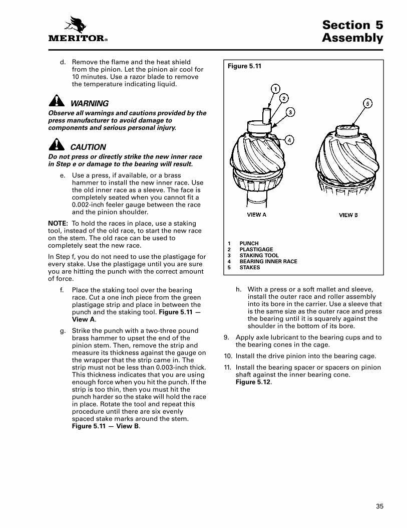
d. Remove the flame and the heat shield from the pinion. Let the pinion air cool for 10 minutes. Use a razor blade to remove the temperature indicating liquid.
WARNINGObserve all warnings and cautions provided by the press manufacturer to avoid damage to components and serious personal injury.
CAUTIONDo not press or directly strike the new inner race in Step e or damage to the bearing will result.
e. Use a press, if available, or a brass hammer to install the new inner race. Use the old inner race as a sleeve. The face is completely seated when you cannot fit a 0.002-inch feeler gauge between the race and the pinion shoulder.
NOTE: To hold the races in place, use a staking tool, instead of the old race, to start the new race on the stem. The old race can be used to completely seat the new race.
In Step f, you do not need to use the plastigage for every stake. Use the plastigage until you are sure you are hitting the punch with the correct amount of force.
f. Place the staking tool over the bearing race. Cut a one inch piece from the green plastigage strip and place in between the punch and the staking tool. Figure 5.11 — View A.
g. Strike the punch with a two-three pound brass hammer to upset the end of the pinion stem. Then, remove the strip and measure its thickness against the gauge on the wrapper that the strip came in. The strip must not be less than 0.003-inch thick. This thickness indicates that you are using enough force when you hit the punch. If the strip is too thin, then you must hit the punch harder so the stake will hold the race in place. Rotate the tool and repeat this procedure until there are six evenly spaced stake marks around the stem. Figure 5.11 — View B.
h. With a press or a soft mallet and sleeve, install the outer race and roller assembly into its bore in the carrier. Use a sleeve that is the same size as the outer race and press the bearing until it is squarely against the shoulder in the bottom of its bore.
9. Apply axle lubricant to the bearing cups and to the bearing cones in the cage.
10. Install the drive pinion into the bearing cage.
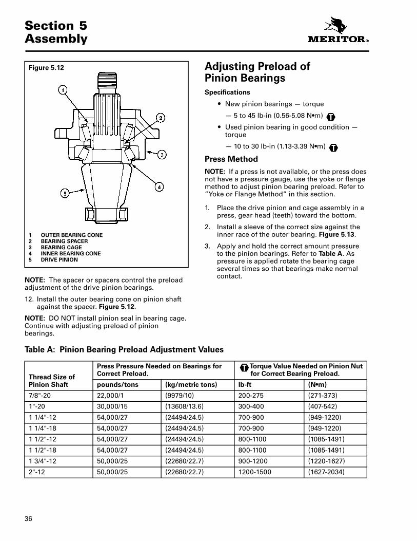
11. Install the bearing spacer or spacers on pinion shaft against the inner bearing cone. Figure 5.12.
Figure 5.11
1 PUNCH2 PLASTIGAGE3 STAKING TOOL4 BEARING INNER RACE5 STAKES
Section 5Assembly
36
NOTE: The spacer or spacers control the preload adjustment of the drive pinion bearings.
12. Install the outer bearing cone on pinion shaft against the spacer. Figure 5.12.
NOTE: DO NOT install pinion seal in bearing cage. Continue with adjusting preload of pinion bearings.
Adjusting Preload of Pinion Bearings
Specifications
� New pinion bearings — torque
— 5 to 45 lb-in (0.56-5.08 N•m)
� Used pinion bearing in good condition — torque
— 10 to 30 lb-in (1.13-3.39 N•m)
Press Method
NOTE: If a press is not available, or the press does not have a pressure gauge, use the yoke or flange method to adjust pinion bearing preload. Refer to “Yoke or Flange Method” in this section.
1. Place the drive pinion and cage assembly in a press, gear head (teeth) toward the bottom.
2. Install a sleeve of the correct size against the inner race of the outer bearing. Figure 5.13.
3. Apply and hold the correct amount pressureto the pinion bearings. Refer to Table A. As pressure is applied rotate the bearing cage several times so that bearings make normal contact.
Table A: Pinion Bearing Preload Adjustment Values
Figure 5.12
1 OUTER BEARING CONE2 BEARING SPACER3 BEARING CAGE4 INNER BEARING CONE5 DRIVE PINION
T
T
Thread Size of Pinion Shaft
Press Pressure Needed on Bearings for Correct Preload.
Torque Value Needed on Pinion Nut for Correct Bearing Preload.
pounds/tons (kg/metric tons) lb-ft (N•m)
7/8"-20 22,000/1 (9979/10) 200-275 (271-373)
1"-20 30,000/15 (13608/13.6) 300-400 (407-542)
1 1/4"-12 54,000/27 (24494/24.5) 700-900 (949-1220)
1 1/4"-18 54,000/27 (24494/24.5) 700-900 (949-1220)
1 1/2"-12 54,000/27 (24494/24.5) 800-1100 (1085-1491)
1 1/2"-18 54,000/27 (24494/24.5) 800-1100 (1085-1491)
1 3/4"-12 50,000/25 (22680/22.7) 900-1200 (1220-1627)
2"-12 50,000/25 (22680/22.7) 1200-1500 (1627-2034)
T

37
Section 5Assembly
4. While pressure is held against the assembly, wind a cord around the bearing cage several times.
5. Attach a spring scale to the end of the cord.
6. Pull the cord with scale on a horizontal line. As the bearing cage rotates, read the value indicated on scale. Write down and record the reading. Figure 5.13.
NOTE: Do not read starting torque. Read only the torque value after the cage starts to rotate. Starting torque will give a false reading.
7. Measure the diameter of bearing cage where the cord was wound. Measure in inches or centimeters. Figure 5.14.
8. Divide the dimension in half to get the radius. Write down and record the radius dimension.
9. Use the following procedure to calculate the bearing preload (torque).
� Pounds Pulled x Radius (inches) =lb-in Preload
— Preload x 0.113 = N•m Preload
� Kilograms Pulled x Radius (cm) = kg-cm Preload
— Preload x 0.098 = N•m Preload
or
Examples
� Reading from spring scale = 7.5 pounds (3.4 kg)
� Diameter of bearing cage = 6.62 inches (16.80 cm)
� Radius of bearing cage = 3.31 inches (8.40 cm)
7.50 lb. x 3.31 in. = 24.80 in-lb Preload
Preload x 0.113 = 2.800 N•m Preload
or
3.4 kg x 8.4 cm = 28.6 kg-cm Preload
Preload x 0.098 = 2.800 N•m Preload
Figure 5.13
1 PRESS2 SLEEVE
Figure 5.14
1 MEASURE DIAMETER OF CAGE.
Section 5Assembly
38
10. If the preload (torque) of pinion bearings is not within specifications, do the following procedure then repeat Steps a through i.
To increase preload, install a thinner bearing spacer. To decrease preload, install a thicker bearing spacer.
11. Inspect the bearing preload with the drive pinion and cage assembly installed in the carrier. Follow the procedures to adjust preload of pinion bearings, yoke or flange method.
Yoke or Flange Method
WARNINGObserve all warnings and cautions provided by the press manufacturer to avoid damage to components and serious personal injury.
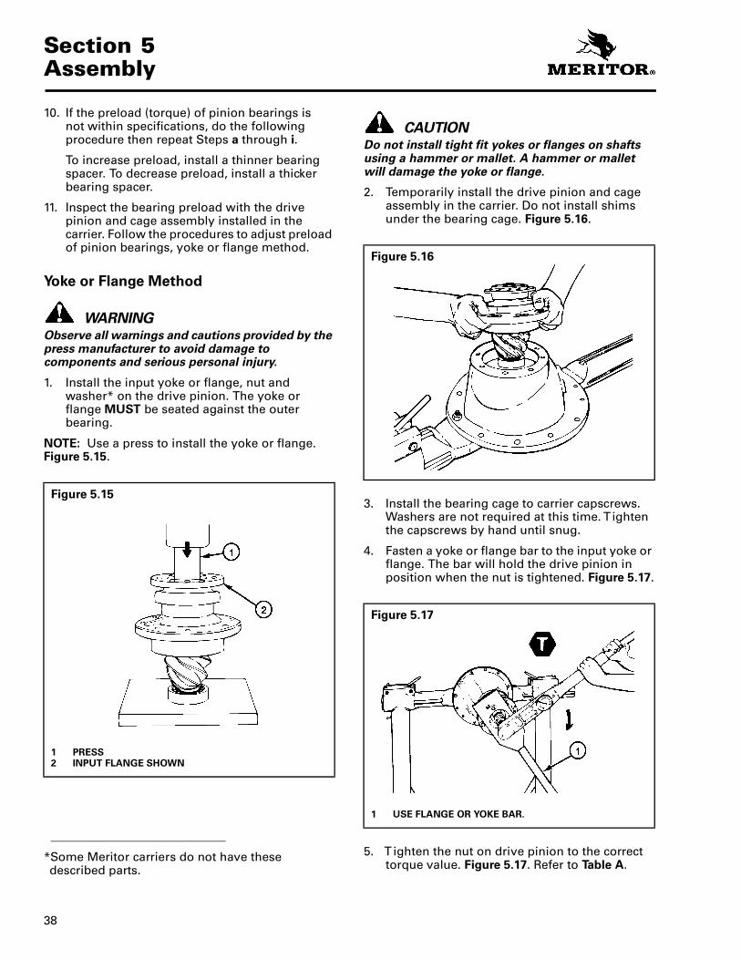
1. Install the input yoke or flange, nut and washer* on the drive pinion. The yoke or flange MUST be seated against the outer bearing.
NOTE: Use a press to install the yoke or flange. Figure 5.15.
CAUTIONDo not install tight fit yokes or flanges on shafts using a hammer or mallet. A hammer or mallet will damage the yoke or flange.
2. Temporarily install the drive pinion and cage assembly in the carrier. Do not install shims under the bearing cage. Figure 5.16.
3. Install the bearing cage to carrier capscrews. Washers are not required at this time. T ighten the capscrews by hand until snug.
4. Fasten a yoke or flange bar to the input yoke or flange. The bar will hold the drive pinion in position when the nut is tightened. Figure 5.17.
5. T ighten the nut on drive pinion to the correct torque value. Figure 5.17. Refer to Table A.
*Some Meritor carriers do not have these described parts.
Figure 5.15
1 PRESS2 INPUT FLANGE SHOWN
Figure 5.16
Figure 5.17
1 USE FLANGE OR YOKE BAR.
39
Section 5Assembly
6. Remove the yoke or flange bar.
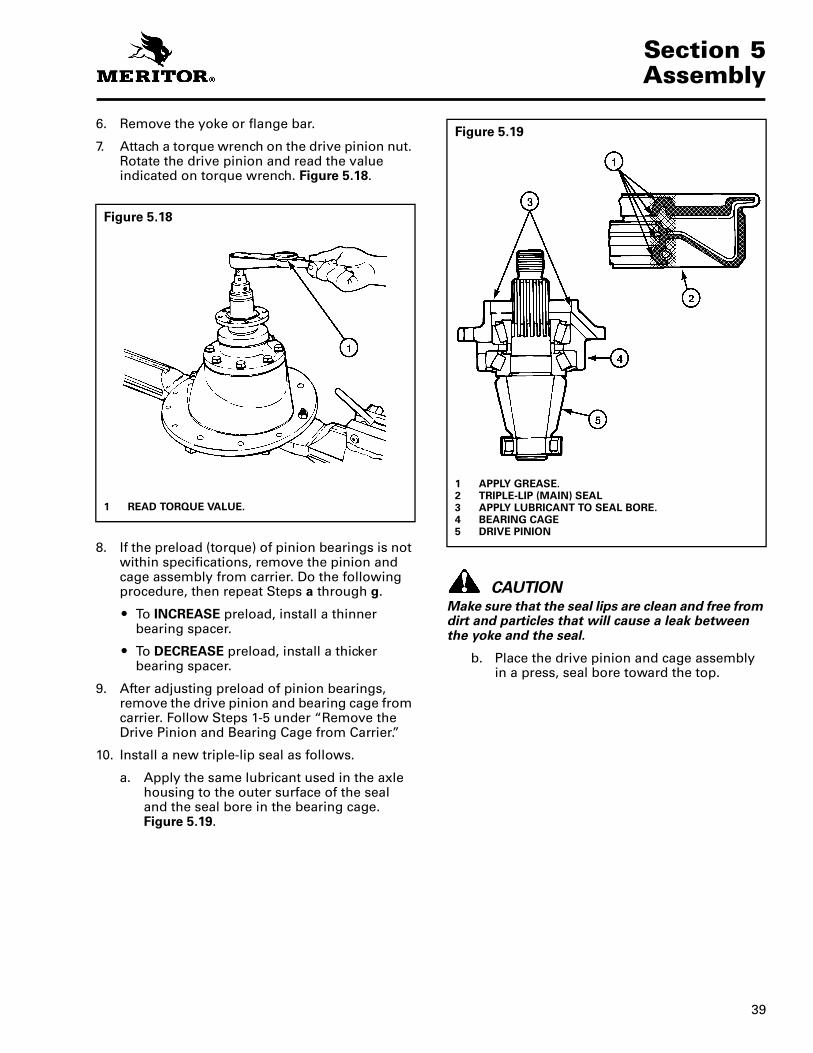
7. Attach a torque wrench on the drive pinion nut. Rotate the drive pinion and read the value indicated on torque wrench. Figure 5.18.
8. If the preload (torque) of pinion bearings is not within specifications, remove the pinion and cage assembly from carrier. Do the following procedure, then repeat Steps a through g.
� To INCREASE preload, install a thinner bearing spacer.
� To DECREASE preload, install a thicker bearing spacer.
9. After adjusting preload of pinion bearings, remove the drive pinion and bearing cage from carrier. Follow Steps 1-5 under “Remove the Drive Pinion and Bearing Cage from Carrier.”
10. Install a new triple-lip seal as follows.
a. Apply the same lubricant used in the axle housing to the outer surface of the seal and the seal bore in the bearing cage. Figure 5.19.
CAUTIONMake sure that the seal lips are clean and free from dirt and particles that will cause a leak between the yoke and the seal.
b. Place the drive pinion and cage assembly in a press, seal bore toward the top.
Figure 5.18
1 READ TORQUE VALUE.
Figure 5.19
1 APPLY GREASE.2 TRIPLE-LIP (MAIN) SEAL3 APPLY LUBRICANT TO SEAL BORE.4 BEARING CAGE5 DRIVE PINION

Section 5Assembly
40
c. Press the seal into bearing cage until flange of seal is flat against the top of bearing cage. Use a sleeve or seal driver of the correct size that fits against the metal flange of seal. The diameter of the sleeve or drive MUST be larger than the diameter of the flange. Figure 5.20.
NOTE: If a press is not available, use a mallet and the sleeve or driver to install the seal. Figure 5.21.
d. After the triple-lip seal is installed, a gap of approximately 0.015- to 0.030-inch (0.38-0.76 mm) between the flange and bearing cage is normal. Figure 5.22.
Inspect the gap with a feeler gauge at several points around the seal. The gap must be within 0.015- to 0.030-inch (0.38-0.76 mm). The difference between the largest and smallest gap measurement MUST NOT exceed 0.010-inch (0.254 mm).
Figure 5.20
1 PRESS2 SLEEVE3 SUPPORTS4 SLEEVE5 SEAL6 BEARING CAGE7 DRIVE PINION
Figure 5.21
1 SEAL DRIVER
Figure 5.22
1 0.015-0.030” (0.38-0.76 MM)
SHOWN WITHOUT BEARINGS AND PINION

41
Section 5Assembly
WARNINGUse a brass or leather mallet for assembly and disassembly procedures. Do not hit steel parts with a steel hammer. Pieces of a part can break off and cause serious personal injury.
Adjusting Shim Pack Thickness for the Pinion Cage (Depth of Pinion)
NOTE: Use this procedure if a new drive pinion and ring gear set is installed, or if the depth of the drive pinion has to be adjusted. Figure 5.23.
1. Measure the thickness of the old shim pack that was removed from under the pinion cage with a micrometer. Record the measurement for use later. Figure 5.24.
2. Look at the pinion cone (PC) variation number on the old drive pinion that is being replaced. Refer to “Gear Set Information,” Step 4, in Section 4 for examples and location of the number. Record the number for later use. If (PC) variation number cannot be located, assemble gear set with shim pack thickness found in Step 1 under “Adjusting Shim Pack Thickness for the Pinion Cage (Depth of Pinion).” Figure 5.25.
Figure 5.23
1 SHIM PACK CONTROLS DEPTH OF PINION.2 BEARING CAGE3 CARRIER
Figure 5.24
Figure 5.25
1 PINION CONE VARIATION NUMBER

Section 5Assembly
42
NOTE: The pinion cone number can be either 100ths of a millimeter or 1,000ths of an inch. Refer to the following examples.
PC +3, PC−3, +3 or −3 = 0.003 inch
PC +.03, PC−0.03 mm, +0.03 mm or −0.03 = 0.03 mm
To change millimeters to inches — millimeters x 0.039
To change inches to millimeters — inches x 25.40
3. If the old pinion cone number is a plus (+) number, subtract the number from the old shim pack thickness that was measured in Step 2.
4. If the old pinion cone number is a minus (−) number, add the number to the old shim pack thickness that was measured in Step 2.
NOTE: The value calculated in Step 3 or 4 is the thickness of the standard shim pack, without a variation.
5. Look at the pinion cone (PC) variation number on the new drive pinion that will be installed. Record the number for later use.
6. If the new pinion cone number is a plus (+) number, add the number to the standard shim pack thickness that was calculated in Step 3 or 4.
7. If the new pinion cone number is a minus (−) number, subtract the number from the standard shim pack thickness that was calculated in Step 3 or 4.
NOTE: The value calculated in Step 6 or 7 is the thickness of the new shim pack that will be installed. Refer to the following examples, Table B.
8. Install the drive pinion, bearing cage and new shim pack into the carrier.
Table B: Shim Pack Thickness Calculations
NOTE: Drive pinions and ring gears MUST be replaced as fully matched sets.
Examples: Inches mm
1. Old Shim Pack ThicknessOld PC Number, PC +2 inches (+0.05 mm)
Standard Shim Pack ThicknessNew PC Number, PC +5 inches (+0.13 mm)
New Shim Pack Thickness
0.030 – 0.002 = 0.028 + 0.005 = 0.033
0.760 – 0.050 = 0.710 + 0.130 = 0.840
2. Old Shim Pack ThicknessOld PC Number, PC –2 inches (–0.05 mm)
Standard Shim Pack ThicknessNew PC Number, PC +5 inches (+0.13 mm)
New Shim Pack Thickness
0.030 + 0.002 = 0.032 + 0.005 = 0.037
0.760 + 0.050 = 0.810 + 0.130 = 0.940
3. Old Shim Pack ThicknessOld PC Number, PC +2 inches (+0.05 mm)
Standard Shim Pack ThicknessNew PC Number, PC –5 inches (–0.13 mm)
New Shim Pack Thickness
0.030 – 0.002 = 0.028 – 0.005 = 0.023
0.760 – 0.050 = 0.710 – 0.130 = 0.580
4. Old Shim Pack ThicknessOld PC Number, PC –2 inches (–0.05 mm)
Standard Shim Pack ThicknessNew PC Number, PC –5 inches (–0.13 mm)
New Shim Pack Thickness
0.030 + 0.002 = 0.032 – 0.005 = 0.027
0.760 + 0.050 = 0.810– 0.130 = 0.608

43
Section 5Assembly
Installing the Drive Pinion, Bearing Cage and Shim Pack into the Carrier
NOTE: If a new drive pinion and ring gear set is installed, or if the depth of the drive pinion has to be adjusted, calculate the thickness of the shim pack. Refer to “Adjusting Shim Pack Thickness for the Pinion Cage (Depth of Pinion)” in this section.
1. Select the correct shim pack between the bearing cage and carrier. Figure 5.26.
2. Apply Loctite® 518 Gasket Eliminator to face of carrier.
3. Align the oil slots in the shims with oil slots in the bearing cage and carrier. The use of guide studs will help align the shims. Figure 5.26.
NOTE: If the pack is made from different thickness shims, install the thinnest shims on both sides of the pack for maximum sealing.
4. Apply Loctite® 518 Gasket Eliminator to top of shim pack.
WARNINGUse a brass or leather mallet for assembly and disassembly procedures. Do not hit steel parts with a steel hammer. Pieces of a part can break off and cause serious personal injury.
5. Install the drive pinion and bearing cage into the carrier. If necessary, use a rubber, plastic or leather mallet to hit the assembly into position. Figure 5.27.
6. If used, install the cover* and seal assembly and gasket* over the bearing cage. Figure 5.28.
Figure 5.26
1 GUIDE STUDS2 THREE SHIMS MINIMUM3 CARRIER
Figure 5.27
1 DRIVE PINION AND BEARING CAGE2 SHIMS3 CARRIER
*Some Meritor carriers do not have these described parts.
Figure 5.28
1 GASKET2 BEARING CAGE3 COVER AND SEAL ASSEMBLY

Section 5Assembly
44
7. Align the oil slots in the cover* and gasket* with oil slot in the bearing cage.
8. Install the bearing cage to carrier capscrews and washers. T ighten capscrews to correct torque value. Refer to Table J. Figure 5.29.
Installing Tight Fit Yokes and POSE™ Seal
CAUTION
Make sure that the seal lips are clean and free from dirt and particles that will cause a leak between the yoke and the seal.
Do not install tight fit yokes on shafts using a hammer or mallet. Using a hammer or mallet can damage the yoke.
1. Apply axle lubricant on the yoke seal.
2. Inspect all surfaces of the yoke hub for damage.
If carrier uses a POSE™ seal element, install a new POSE™ seal as follows:
a. Lightly lubricate yoke journal with same lubricant used in the axle housing.
CAUTIONMake sure that the seal lips are clean and free from dirt and particles that can cause a leak between the yoke and the POSE™ seal.
b. Partially install the POSE™ seal onto the yoke to 1/4-inch – 1/2-inch as shown in Figure 5.30.
NOTE: DO NOT install POSE™ seal all the way against the yoke shoulder. This seal is designed to position itself as yoke is installed.
c. Before installing the yoke onto the drive pinion, lubricate the yoke again with the same lubricant used in the axle housing.
3. Slide the yoke over the input shaft pinion. Align the yoke splines with the shaft splines.
CAUTIONDo not use a hammer or mallet to install the yoke to the input pinion shaft. Using a hammer or mallet can damage the yoke or flange.
4. Install the input yoke flange onto the drive pinion shaft. The yoke or flange must be fully seated against the outer differential bearing BEFORE the nut is torqued to specifications.
*Some Meritor carriers do not have these described parts.
Figure 5.29
Figure 5.30
1 LUBRICATE TRIPLE-LIP (MAIN) SEAL.2 INPUT SHAFT (PINION)3 POSE™ SEAL 0.25”–0.50” (6.4 MM–12.7 MM) ONTO
HUB4 INSPECT YOKE HUB.

45
Section 5Assembly
5. Install the drive pinion nut on the input pinion shaft and against the yoke collar. T ighten the nut against yoke collar to torque specifications. Figure 5.31. Refer to Table J.
Assemble the Main Differential and Ring Gear Assembly
CAUTIONDo not press a cold ring gear on the flange case half. A cold ring gear will damage the case half because of the tight fit. Metal particles between the parts will cause gear runout that exceeds the Meritor specification of 0.008-inch (0.200 mm).
1. Expand the ring gear by heating the gear in a tank of water to a temperature of 160°F to 180°F (71°C-82°C) for 10 to 15 minutes.
WARNINGWear safe clothing and gloves for protection from injury when working with the hot ring gear.
2. Safely lift the ring gear from the tank of water using a lifting tool.
3. Install the ring gear on the flange case half immediately after the gear is heated. If the ring gear does not fit easily on the case half, heat the gear again. Repeat Step 1.
4. Align fastener holes of the ring gear and flange case half. Rotate the ring gear as needed.
5. If rivets* were used to hold the ring gear to the flange case half, replace them with bolts, nuts and washers.
6. Install the bolts*, nuts* and washers* that hold the ring gear to the flange case half. Install the bolts from the gear side of the assembly. The bolt heads MUST be against the ring gear. Figure 5.32.
7. T ighten the bolts* and nuts* to the correct torque value. Refer to Table J.
8. Inspect for gaps between the back surface of the ring gear and the case flange after the bolts are installed. Use an 0.003-inch (0.080 mm) feeler gauge and inspect at four points around the assembly. Figure 5.33.
Figure 5.31
1 USE FLANGE OR YOKE BAR.
T
Figure 5.32
1 FLANGE CASE HALF2 RING GEAR3 BOLT HEAD AGAINST GEAR
*Some Meritor carriers do not have these described parts.
Figure 5.33
1 CHECK FOR 0.003” GAP AT FOUR LOCATIONS.
T
Section 5Assembly
46
9. Inspect the flange case half and ring gear for the problem that causes the gap. Repair or replace parts that do not meet specifications.
10. Assemble the repaired or replaced ring gear on the flange case half. Repeat the Main Differential and Ring Gear Assembly procedure.
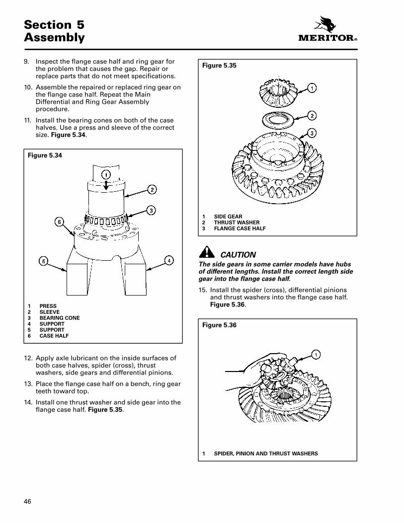
11. Install the bearing cones on both of the case halves. Use a press and sleeve of the correct size. Figure 5.34.
12. Apply axle lubricant on the inside surfaces of both case halves, spider (cross), thrust washers, side gears and differential pinions.
13. Place the flange case half on a bench, ring gear teeth toward top.
14. Install one thrust washer and side gear into the flange case half. Figure 5.35.
CAUTIONThe side gears in some carrier models have hubs of different lengths. Install the correct length side gear into the flange case half.
15. Install the spider (cross), differential pinions and thrust washers into the flange case half. Figure 5.36.
Figure 5.34
1 PRESS2 SLEEVE3 BEARING CONE4 SUPPORT5 SUPPORT6 CASE HALF
Figure 5.35
1 SIDE GEAR2 THRUST WASHER3 FLANGE CASE HALF
Figure 5.36
1 SPIDER, PINION AND THRUST WASHERS

47
Section 5Assembly
16. Install the second side gear and thrust washer over spider and differential pinions. Figure 5.37.
17. Place the plain half of the differential case over the flange half and gears. Rotate the plain half as needed to align the match marks. Figure 5.37 and Figure 5.38.
18. Install Dri-Loc fasteners into the case halves. Refer to “Application of Three Bond 1216 or Equivalent Silicone Gasket Material” in Section 4 and the following Steps a and b.
a. Install four capscrews* and washers* or bolts*, nuts* and washers* into the case halves. The distance between the fasteners MUST be equal. T ighten the fasteners to the correct torque value in a progressive criss-cross pattern opposite each other. Refer to Figure 5.39 and to Table J.
b. Install the other fasteners into the case halves. T ighten the fasteners to the correct torque value. Refer to Table J.
19. Inspect the rotating resistance of the differential gears. Use the following procedure.
Figure 5.37
1 THRUST WASHER2 SIDE GEAR3 PLAIN CASE HALF
Figure 5.38
1 PLAIN CASE HALF2 MATCH MARKS
*Some Meritor carriers do not have these described parts.
Figure 5.39
T
T

Section 5Assembly
48
Inspecting the Rotating Resistance of the Differential Gears
Specification
� 50 lb-ft (67.8 N•m) maximum torque applied to one side gear.
NOTE: Make a tool for inspecting the rotating resistance of the differential gears. The tool can be made from an axle shaft that matches the spline size of the differential side gear. Refer to Figure 5.40 and Figure 5.41.
1. Install soft metal covers over vise jaws to protect the ring gear. Figure 5.41.
2. Place the differential and ring gear assembly in the vise and close the vise jaws.
3. Install the tool into the differential until the splines of the tool and one side gear are engaged. Figure 5.41.
4. Engage a torque wrench to the nut of the tool and rotate the differential gears. As the differential gears rotate, read the value indicated on the torque wrench. Figure 5.42.
5. If the torque value exceeds the specification, disassemble the differential gears from the case halves.
6. Inspect the case halves, spider, gears and thrust washers for the problem that causes the torque value to exceed the specification. Repair or replace parts.
7. After all the differential assembly parts are repaired or replaced, assemble the parts and repeat Steps 1 through 7.
Figure 5.40
1 APPROXIMATELY 12-INCHES (304.8 MM)2 SIDE VIEW3 WELD NUT TO END OF SHAFT.4 END VIEW
T
Figure 5.41
1 TOOL FOR CHECKING RESISTANCE2 SOFT METAL COVER
Figure 5.42
1 READ TORQUE VALUE.

49
Section 5Assembly
Install the Differential and Ring Gear Assembly
1. Clean and dry the bearing cups and bores of the carrier legs and bearing caps.
2. Apply axle lubricant on the inner diameter of the bearing cups and on both bearing cones that are assembled on the case halves.
3. Apply Meritor Adhesive into the bearing bores of the carrier legs and bearing caps. Make certain not to allow adhesive to contact adjusting ring threads. Refer to “Application of Three Bond 1216 or Equivalent Silicone Gasket Material” in Section 4. Figure 5.43.
4. Install the bearing cups over the bearingcones that are assembled on the case halves. Figure 5.44.
5. Safely lift the differential and ring gear assembly and install into the carrier. The bearing cups MUST be flat against the bores between the carrier legs. Figure 5.44.
6. Install both of the bearing adjusting rings into position between the carrier legs. Turn each adjusting ring hand-tight against the bearing cup. Figure 5.45.
Figure 5.43
1 ADHESIVE2 BEARING CAP3 CARRIER LEG
Figure 5.44
1 BEARING CUP2 BEARING CUP3 LEG BORE
Figure 5.45
1 ADJUSTING RING2 LEG

Section 5Assembly
50
7. Install the bearing caps over the bearings and adjusting rings in the correct location as marked before removal. Figure 5.46.
WARNINGUse a brass or leather mallet for assembly and disassembly procedures. Do not hit steel parts with a steel hammer. Pieces of a part can break off and cause serious personal injury.
8. Seat each bearing cap with a light leather, plastic or rubber mallet. The caps MUST fit easily against the bearings, adjusting rings and carrier. Do not force the bearing caps into position.
CAUTIONIf bearing caps are not installed in the correct original locations, the bores and threads in caps will not match the carrier. Assembling mismatched caps into the carrier can result in carrier damage after reassembly to axle and during vehicle operation. Do not force the bearing caps into unmatched bore locations in the carrier.
9. If bearing caps do not correctly fit into position, inspect the alignment of match marks between caps and carrier. Remove the caps and repeat Steps 6-8.
10. Install the capscrews and washers that hold bearing caps to the carrier. T ighten the capscrews by hand four to six turns, then tighten the capscrews to the correct torque value. Refer to Table J.
NOTE: Do not install the cotter keys*, pins* or lock plates* that hold the bearing adjusting rings in position. Continue by adjusting the preload of differential bearings, adjust backlash of the hypoid gear and inspect tooth contact patterns.
* Some Meritor carriers do not have thesedescribed parts.
Adjust Preload of Differential Bearings
Specifications
� Preload of differential bearings (all carrier models)
— 15 to 35 lb-in (1.7-3.9 N•m) torque.
� Expansion between bearing caps (leg spread)
— R-140, R-155 and R-160 carrier models: 0.002- to 0.009-inch (0.050-0.229 mm)
— R, S, U and W 120 series and most (check latest specifications) other carrier models: 0.00- to 0.013-inch (0.150-0.330 mm)
Method 1
1. Attach a dial indicator on the mounting flange of the carrier.
2. Adjust the dial indicator so that the plunger or pointer is against the back surface of the ring gear. Figure 5.47.
Figure 5.46
1 BEARING CAP2 MATCH MARKS
Figure 5.47
1 DIAL INDICATOR
T
T

51
Section 5Assembly
CAUTIONWhen you turn the adjusting rings, always use a tool that engages two or more opposite notches in the ring. A “T” bar wrench can be used for this purpose. If the tool does not correctly fit into the notches, damage to the lugs will occur. Figure 5.48.
3. Loosen the bearing adjusting ring that is opposite the ring gear so that a small amount of end play shows on the dial indicator. Figure 5.48. Move the differential and ring gear to the left and right with pry bars while you read the dial indicator. Use the following Step a or b.
a. Use two pry bars that fit between the bearing adjusting rings and ends of the differential case. The pry bars MUST NOT touch the differential bearings. Figure 5.49.
b. Use two pry bars between the differential case or ring gear and the carrier at locations other than described in Step a. The pry bars MUST NOT touch the differential bearings. Figure 5.50.
Figure 5.48
1 “T” BAR WRENCH2 ADJUSTING RING OPPOSITE RING GEAR
Figure 5.49
1 BARS MUST NOT TOUCH BEARINGS.
Figure 5.50
1 BARS MUST NOT TOUCH BEARINGS.

Section 5Assembly
52
4. T ighten the same bearing adjusting ring so that no end play shows on the dial indicator. Move the differential and ring gear to the left and right as needed. Repeat Step a or b.
5. T ighten each bearing adjusting ring one notch from the zero end play measured in Step 4.
6. Continue by checking runout of the ring gear.
Method 2
A second method of inspecting preload is to measure the expansion between the bearing caps (leg spread) after the adjusting rings are tightened. Use the following procedure.
1. Turn both adjusting rings hand tight against the differential bearings.
2. Measure the distance X or Y between opposite surfaces of the bearing caps. Use a large micrometer of the correct size. Figure 5.51 and Figure 5.52. Record the measurement.
3. T ighten each bearing adjusting ring one notch.
4. Measure the distance X or Y again. Compare the dimension with the distance X or Y measured in Step 2. The difference between the two dimensions is the amount the bearing caps have expanded.
Example
� Measurements of R-155 carrier
� Distance X or Y
— before tightening adjusting rings = 13.927-inch (353.740 mm)
� Distance X or Y
— after tightening adjusting rings = 13.936-inch (353.970 mm)
� 13.936-inch − 13.927-inch = 0.009-inch (0.230 mm) difference
If the dimension is within specifications, continue by checking runout of the ring gear. If the dimension is less than specifications, repeat Steps 3 and 4 as needed.
Figure 5.51
Figure 5.52
1 MICROMETER

53
Section 5Assembly
Inspect Runout of Ring Gear
Runout Specification
� 0.008-inch (0.200 mm)
1. Attach a dial indicator on the mounting flange of the carrier. Figure 5.53.
2. Adjust the dial indicator so that the plunger or pointer is against the back surface of the ring gear.
3. Set the dial indicator to zero (0).
4. Rotate the differential and ring gear and read the dial indicator. The runout of the ring gear must not exceed 0.008-inch (0.200 mm). Figure 5.53.
If runout of the ring gear exceeds specifications, remove the differential and ring gear assembly from the carrier. Refer to “Remove the Differential and Ring Gear from the Carrier” in Section 2 and the following Steps 5 and 6.
5. Inspect the differential parts including the carrier for the problem that causes the runout of gear to exceed specifications. Repair or replace parts.
6. After the parts are repaired or replaced, install the differential and ring gear into the carrier. Refer to “Install the Differential and Ring Gear Assembly” in this section.
7. Repeat preload adjustment of differential bearings.
Ring Gear Backlash Adjustment
Specifications
� Ring gears that have a pitch diameter of less than 17-inches (431.8 mm)
— Range of backlash setting: 0.008- to 0.018-inch (0.200-0.460 mm).
— Backlash setting for new gear sets: 0.012-inch (0.300 mm)
� Ring gears that have a pitch diameter greater than 17-inches (431.8 mm)
— Range of backlash setting: 0.010- to 0.020-inch (0.250-0.510 mm)
— Backlash setting for new gear sets: 0.015-inch (0.380 mm)
NOTE: Measure the outer diameter of ring gear for approximate pitch diameter. Figure 5.54.
If the old gear set is installed, adjust the backlash to the setting that was measured before the carrier was disassembled.
If a new gear set is installed, adjust the backlash to the correct specification for new gear sets.
After inspection of the tooth contact patterns, the backlash can be adjusted within specification limits, if needed. To change the location of the pattern use the following procedures.
Figure 5.53
1 ROTATE RING GEAR.2 DIAL INDICATOR
Figure 5.54
1 MEASURE OUTER DIAMETER FOR APPROXIMATE. PITCH DIAMETER

Section 5Assembly
54
1. Attach a dial indicator on the mounting flange of the carrier. Figure 5.55.
2. Adjust the dial indicator so that the plunger or pointer is against the tooth surface. Figure 5.55.
3. Adjust the indicator dial to zero (0).
4. Hold the drive pinion in position.
5. After reading the dial indicator, rotate the differential and ring gear a small amount in both directions, against the drive pinion teeth. If the backlash reading is within specification, continue inspecting tooth contact patterns. If the backlash reading is not within specifications, adjust backlash as needed. Continue following Steps 6 and 7.
NOTE: Backlash is increased by moving the ring gear away from the drive pinion. Figure 5.56.
Backlash is decreased by moving the ring gear toward the drive pinion. Figure 5.57.
6. Loosen one bearing adjusting ring one notch then tighten the opposite ring the same amount. Refer to Figure 5.56 and Figure 5.57.
NOTE: When you adjust backlash, move the ring gear ONLY. DO NOT move the drive pinion.
7. Repeat Steps 2-6 until the backlash is within specifications.
Figure 5.55Figure 5.56
1 TIGHTEN ADJUSTING RING THIS SIDE.2 INCREASE BACKLASH.3 LOOSEN ADJUSTING RING THIS SIDE.
Figure 5.57
1 LOOSEN ADJUSTING RING THIS SIDE.2 DECREASE BACKLASH.3 TIGHTEN ADJUSTING RING THIS SIDE.

55
Section 5Assembly
Inspect Tooth Contact Patterns of the Gear Set
General Information
Meritor carriers can have a conventional HYPOID gear set or a GENEROID hypoid gear set. Thetooth contact patterns for each type of gear set are different. Look at the part numbers to see what type of gear set is in the carrier. Refer to Figure 5.58 for the location of part numbers.
Examples of part numbers for conventional HYPOID gear sets.
� 36786 for the ring gear.
� 36787 for the drive pinion.
Examples of part numbers for GENEROID gear sets.
� 36786-K or 36786-K2 for the ring gear.
� 36787-K or 36787-K2 for the drive pinion.
In the following procedures, movement of the contact pattern in the length of the tooth is indicated as, toward the “heel” or “toe” of the ring gear. Figure 5.59.
Always inspect tooth contact patterns on the drive side of the gear teeth. Figure 5.60.
Figure 5.58
1 PART NO.2 PART NO.3 PART NO. OPTION
Figure 5.59
1 HEEL2 TOE
Figure 5.60
1 DRIVE SIDE (CONVEX)

Section 5Assembly
56
Tooth Contact Patterns of Conventional Hypoid and Generoid Hypoid Gear Sets
1. Adjust the backlash of a new gear set to either 0.012-inch (0.305 mm) or 0.015-inch (0.380 mm) depending on the size of the ring gear. Adjust the backlash of an old gear set to the setting that was measured before the carrier was disassembled. Refer to ”Ring Gear Backlash Adjustment” in this section.
2. Apply a marking compound to approximately 12 gear teeth of the ring gear. Rotate the ring gear so that the 12 gear teeth are next to the drive pinion. Figure 5.61.
3. Rotate ring gear forward and backward so that the 12 gear teeth go past the drive pinion six times to get the contact patterns. Repeat if needed to get a more clear pattern.
4. Look at the contact patterns on the ring gear teeth. Compare the patterns to Figure 5.62 or Figure 5.65, Figure 5.63 or Figure 5.66, and Figure 5.64 or Figure 5.67.
The Location of Good Hand-Rolled Contact Patterns.
New Conventional and Generoid Gear Sets — toward the toe of the gear tooth and in the center between the top and bottom of the tooth. Refer to Figure 5.62 and Figure 5.65.
When the carrier is being operated, a good pattern will extend approximately the full length of the gear tooth. The top of the pattern will be near the top of the gear tooth. Refer to Figure 5.68 or Figure 5.69.
The location of a good hand-rolled contact pattern for an old gear set MUST match the wear pattern in the ring gear. The contact pattern will be smaller in area than the wear pattern.
If the contact patterns require adjustment, continue by following Step 5 to move the contact patterns between the top and bottom of the gear teeth. If the contact patterns are in the center of the gear teeth, continue by following Step 6.
Figure 5.61
Figure 5.62
Good Hand-Rolled Pattern/Conventional Gears
Figure 5.63
High Pattern/Conventional Gears

57
Section 5Assembly
Figure 5.64
Low Pattern/Conventional Gears
Figure 5.65
Good Hand-Rolled Pattern/Generoid Gears
Figure 5.66
High Pattern/Generoid Gears
Figure 5.67
Low Pattern/Generoid Gears
Figure 5.68
Good Pattern in Operation Conventional Gears
Figure 5.69
Good Pattern in Operation Generoid Gears

Section 5Assembly
58
5. Change the thickness of the shim pack under bearing cage to move the contact patterns between the top and bottom of the gear teeth. Use the following procedure.
a. Remove the drive pinion and bearing cage from the carrier. Refer to “Remove the Drive Pinion and Bearing Cage from Carrier” in Section 2.
NOTE: A high contact pattern indicates that the drive pinion was not installed deep enough into the carrier. A low contact pattern indicates that the drive pinion was installed too deep in the carrier.
b. To correct a high contact pattern, Figure 5.63, decrease the thickness of the shim pack under the bearing cage. When decreasing the thickness of the shim pack, the drive pinion will move toward the ring gear. Figure 5.70.
To correct a low contact pattern, Figure 5.71, increase the thickness of shim pack under the bearing cage. When increasing the thickness of the shim pack, the drive pinion will move away from the ring gear. Figure 5.71.
c. Install the drive pinion, bearing cage and shims into the carrier. Refer to “Adjusting Shim Pack Thickness for the Pinion Cage (Depth of Pinion)” in this section.
d. Repeat Steps 2-5 until the contact patterns are in the center between the top and bottom of the gear teeth.
6. Adjust backlash of the ring gear within specification range to move the contact patterns to the correct location in the length of the gear teeth. Refer to “Ring Gear Backlash Adjustment” in this section.
a. Decrease backlash to move the contact patterns toward the toe of the ring gear teeth. Figure 5.72.
Figure 5.70
1 DECREASE SHIM PACK.
Figure 5.71
1 INCREASE SHIM PACK.
Figure 5.72
1 MOVE PATTERN TOWARD TOE, LOOSEN ADJUSTING RING THIS SIDE.
2 DECREASE BACKLASH.3 TIGHTEN ADJUSTING RING.

59
Section 5Assembly
b. Increase backlash to move the contact patterns toward the heel of the ring gear teeth. Figure 5.73.
c. Repeat Steps 2-4 and 6 until the contact patterns are at the correct location in the length of the gear teeth.
CAUTIONIf the carrier has cotter keys, lock the adjusting rings only with cotter keys. If your carrier has roll pins, reuse the roll pins or lock the adjusting rings with cotter keys. Do not force a roll pin into a cotter key hole.
7. Install cotter keys*, pins*, or lock plates* that hold the two bearing adjusting rings in position. Use the following procedures.
a. Cotter Keys* — Install cotter keys between lugs of the adjusting ring and through the boss of the bearing cap. Bend the two ends of the cotter key around the boss. Figure 5.74.
b. Pins* — Install pin through boss of the bearing cap until the pin is between lugs of the adjusting ring. Use a drift and hammer to install the pin. Figure 5.74.
c. Lock Plates* — Install lock plate on bearing cap so that the tab is between lugs of the adjusting ring. Install the two capscrews that hold the lock plate to the bearing cap. T ighten the capscrews to correct torque value. Refer to Table J. Figure 5.74.
Figure 5.73
1 MOVE PATTERN TOWARD TOE, LOOSEN ADJUSTING RING THIS SIDE.
2 DECREASE BACKLASH.3 LOOSEN ADJUSTING RING.
*Some Meritor carriers do not have these described parts.
Figure 5.74
1 COTTER KEY2 PIN3 LOCK PLATE4 THREADED HOLES IN CAP WHEN LOCK PLATE IS USED
SHOWN WITH COTTER KEY INSTALLED
T

Section 5Assembly
60
Install and Adjust the Thrust Screw*
Specification
� Clearance between thrust screw and ring gear
— 0.025- to 0.045-inch (0.650-1.140 mm).
� Loosen the thrust screw 1/2 turn or 180°.
If the carrier does not have a thrust block*, start at Step 4.
1. Rotate the carrier in the repair stand until the back surface of ring gear is toward the top. Figure 5.75.
2. Place the thrust block* on the back surface of the ring gear. The thrust block* MUST be in the center between the outer diameter of gear and differential case.
3. Rotate the ring gear until the thrust block* and hole for thrust screw, in carrier, are aligned. Figure 5.75.
4. Install the jam nut* on the thrust screw*, one half the distance between both ends.
5. Install the thrust screw* into the carrier until the screw stops against the ring gear or thrust block*. Figure 5.76.
6. Loosen the thrust screw* 1/2 turn, 180°. Figure 5.77.
*Some Meritor carriers do not have these described parts.
Figure 5.75
1 HOLE FOR THRUST SCREW2 THRUST BLOCK
Figure 5.76
1 THRUST SCREW AND JAM NUT
Figure 5.77
1 LOOSEN THRUST SCREW 1/2 TURN.
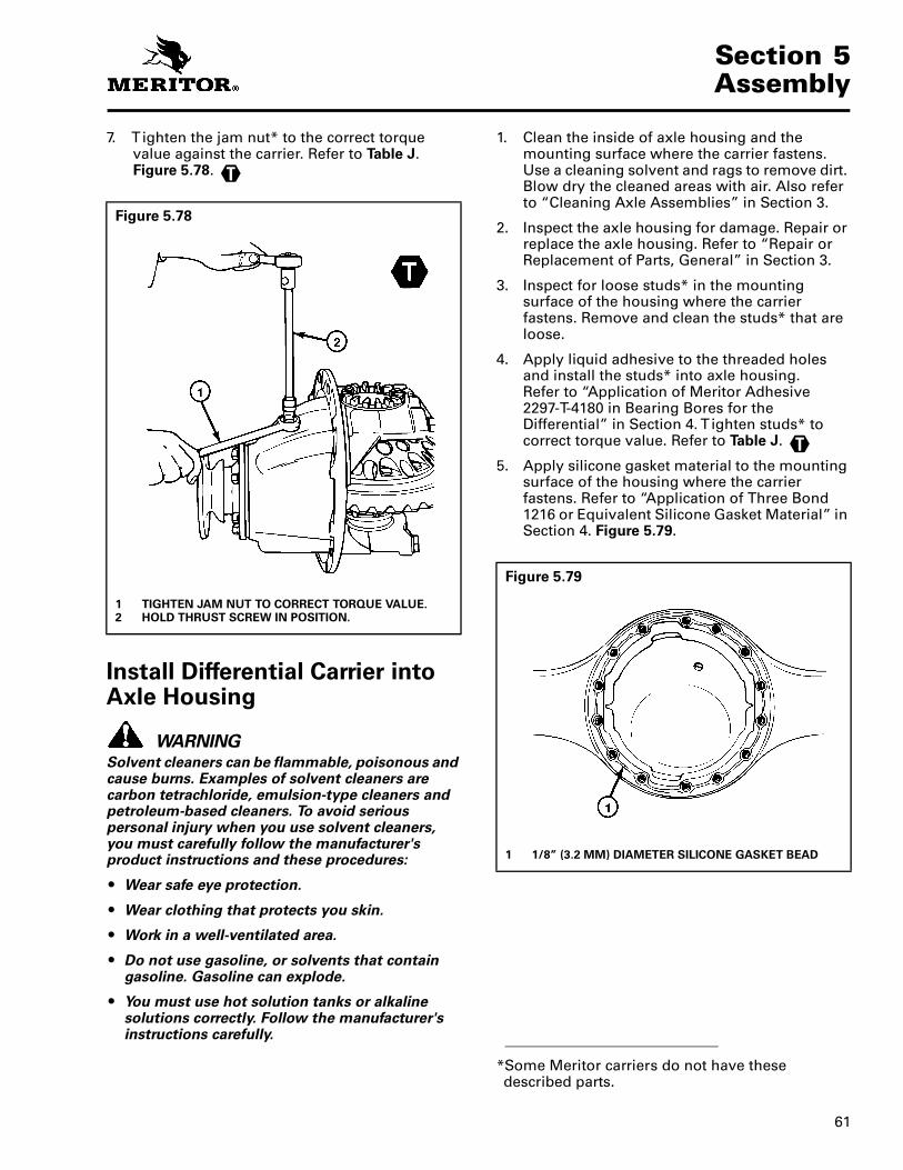
61
Section 5Assembly
7. T ighten the jam nut* to the correct torque value against the carrier. Refer to Table J. Figure 5.78.
Install Differential Carrier into Axle Housing
WARNINGSolvent cleaners can be flammable, poisonous and cause burns. Examples of solvent cleaners are carbon tetrachloride, emulsion-type cleaners and petroleum-based cleaners. To avoid serious personal injury when you use solvent cleaners, you must carefully follow the manufacturer's product instructions and these procedures:
� Wear safe eye protection.
� Wear clothing that protects you skin.
� Work in a well-ventilated area.
� Do not use gasoline, or solvents that contain gasoline. Gasoline can explode.
� You must use hot solution tanks or alkaline solutions correctly. Follow the manufacturer's instructions carefully.
1. Clean the inside of axle housing and the mounting surface where the carrier fastens. Use a cleaning solvent and rags to remove dirt. Blow dry the cleaned areas with air. Also refer to “Cleaning Axle Assemblies” in Section 3.
2. Inspect the axle housing for damage. Repair or replace the axle housing. Refer to “Repair or Replacement of Parts, General” in Section 3.
3. Inspect for loose studs* in the mounting surface of the housing where the carrier fastens. Remove and clean the studs* that are loose.
4. Apply liquid adhesive to the threaded holes and install the studs* into axle housing. Refer to “Application of Meritor Adhesive2297-T-4180 in Bearing Bores for the Differential” in Section 4. T ighten studs* to correct torque value. Refer to Table J.
5. Apply silicone gasket material to the mounting surface of the housing where the carrier fastens. Refer to “Application of Three Bond 1216 or Equivalent Silicone Gasket Material” in Section 4. Figure 5.79.
Figure 5.78
1 TIGHTEN JAM NUT TO CORRECT TORQUE VALUE.2 HOLD THRUST SCREW IN POSITION.
T
*Some Meritor carriers do not have these described parts.
Figure 5.79
1 1/8” (3.2 MM) DIAMETER SILICONE GASKET BEAD
T

Section 5Assembly
62
6. Install the carrier into the axle housing. Use a hydraulic roller jack or a lifting tool.
CAUTIONDo not use a hammer or a mallet to install the carrier. A hammer or a mallet will damage the mounting flange of the carrier and cause oil leaks.
7. Install the nuts* and the washers or the capscrews and washers in the four corner locations around the carrier and the axle housing. T ighten the fasteners by hand. Do not tighten to the specified torque. Figure 5.80.
8. Carefully push the carrier into position. T ighten the four fasteners two or three turns each in a pattern opposite each other. Refer to Figure 5.80.
9. Repeat Step 9 until the four fasteners are tightened to the correct torque value.
� Fasteners with standard flat washers: T ighten fasteners to 150-230 lb-ft (203-312 N•m).
10. Install the remaining fasteners and washers that hold the carrier in the axle housing. T ighten fasteners to the correct torque value. Refer to Table J.
11. Connect the driveline universal joint to the pinion input yoke or flange on the carrier.
12. Install the gaskets and axle shafts into the axle housing and carrier. The gasket and flange of the axle shafts MUST fit flat against the wheel hub. Figure 5.81.
*Some Meritor carriers do not have these described parts.
Figure 5.80
T
T
Figure 5.81
1 TAPERED DOWEL RETENTION
2 STUD NUT3 WASHER4 TAPERED DOWEL5 GASKET6 STUD
7 SHAFT HUB AXLE8 AXLE SHAFT (FLANGE)9 WASHER10 CAPSCREW11 NON-TAPERED DOWEL
RETENTION

63
Section 5Assembly
Straight Holes, Nuts and Hardened Washers
1. Clean the mating surfaces of the axle shaft and the wheel hub.
2. If silicone gasket material is used, apply a 1/8-inch diameter bead of the gasket material around the mating surface of the hub and around the edge of each fastener hole inthat surface.
3. Install the gasket and the axle shaft into the housing. The gasket and the flange of the axle shaft MUST fit flat against the wheel hub. Refer to Figure 5.81.
4. Install the Grade 8 nuts and hardened washers on the stud. (Lock washers are an acceptable alternative.) T ighten the stud nuts to the torque specified in Table C.
Tapered Dowel, Hardened Washer and Hardened Nut
1. Clean the mating surfaces of the axle shaft and the wheel hub.
2. If silicone gasket material is used, apply a 1/8-inch diameter bead of the gasket material around the mating surface of the hub and around the edge of each fastener hole in that surface.
3. Install the gasket and the axle shaft into the housing. The gasket and the flange of the axle shaft MUST fit flat against the wheel hub. Refer to Figure 5.81.
4. Install solid tapered dowels over each stud and into the flange of the axle shaft. Use a punch or a drift and hammer, if necessary.
5. Install the Grade 8 nuts and hardened washers on the stud. (Lock washers are an acceptable alternative.) T ighten the stud nuts to the torque specified in Table D.
Table C: Shaft-to-Hub Torque Fastener — Non-tapered Dowel Applications
Table D: Shaft-to-Hub Torque Fastener — Tapered Dowel Applications
Fastener Thread Size
Torque Value — Grade 8 Nuts lb-ft (N•m)
Plain Nut Lock Nut
Stud Nut
(Axle Shaft)
.62-18
.75-16
150-230 (203-312)
310-400 (420-542)
130-190 (176-258)
270-350 (366-475)
Studs All Install the course thread end of stud into hub and tighten to last thread.
Fastener Thread Size
Torque Value — Grade 8 Nuts lb-ft (N•m)
Plain Nut Lock Nut
Stud Nut
(Axle Shaft)
.44-20
.50-20
.56-18
.62-18
50-75 (81-102)
75-115 (115-156)
110-165 (176-224)
150-230 (203-312)
40-65 (67-88)
65-100 (102-136)
100-145 (149-197)
130-190 (176-258)
Studs All Install the course thread end of stud into hub and tightento last thread.
T
T

Section 6Lubrication
64
Section 6Lubrication
NOTE: For complete information on lubricating drive axles and carriers, refer to Maintenance Manual 1, Lubrication.
Refer to Table E, Table F and Table I for standard information on lubricants, schedules and capacities.
Table E: Lubricant Cross Reference (Viscosity) and Temperature
Table F: Rear Drive Axle Oil Change Intervals and Specifications �
APPLIES TO ALL REAR AXLES EXCEPT THE “ADVANCED LUBE” REAR AXLES.
NOTES
� If oil pump and filter is used, change filter every 100,000 miles (160,000 km). Inspect oil level. Add correct oil as required.
� Includes heavy-duty on-highway and on/off-highway applications.
� For continuous heavy-duty operation, inspect oil level every 1,000 miles (1,600 kilometers).
Meritor Lubricant Specification Description Cross Reference
Minimum Outside Temperature
Maximum Outside Temperature
O-76-A Hypoid Gear Oil GL-5, S.A.E. 85W/140 +100°F (–12.2°C) - - -**
O-76-B Hypoid Gear Oil GL-5, S.A.E. 80W/140 –15°F (–26.1°C) - - -**
O-76-D Hypoid Gear Oil GL-5, S.A.E. 80W/90 –15°F (–26.1°C) - - -**
O-76-E Hypoid Gear Oil GL-5, S.A.E. 75W/90 –40°F (–40°C) - - -**
O-76-J Hypoid Gear Oil GL-5, S.A.E. 75W –40°F (–40°C) + 35°F (+ 1.6°C)
O-76-L Hypoid Gear Oil GL-5, S.A.E. 75W/140 –40°F (–40°C) - - -**
**There is no upper limit on these outside temperatures, but the axle sump temperature must never exceed 250�F (+ 121�C).
On-Highway Operation Intervals Off-Highway Operation Intervals�
Meritor Specifications (Military)
Oil Description
Outside Temperature
Initial Oil Change
Inspect Oil Level
Petroleum Oil Change
Synthetic Oil Change
Initial Oil Change
Inspect Oil Level
Petroleum Oil Change�
Synthetic Oil Change
F° C°
Min. Max. Min. Max.
3,000 miles (4,800 km)
3,000 miles (4,800 km), once a month or the fleet maint-enance interval (whichever comes first)
If annual mileage is less than 100,000 miles (160,000 km) change oil once a year.
250,000 miles (400,000 km)
1,000 miles (1,600 km)
1,000 miles (1,600 km)
If annual mileage is less than 60,000 miles (96,000 km) change oil twice a year.
50,000 miles (80,000 km)
O-76A, Gear Oil (MIL-L-2105D or MIL-PRF-2105E)
GL-5, SAE 85W/140
10 None –12 None
O-76D, Gear Oil (MIL-L-2105D or MIL-PRF-2105E)
GL-5, SAE 80W/90
–15 None –26 None
O-76E, Gear Oil (MIL-L-2105D or MIL-PRF-2105E)
GL-5, SAE 75W/90
–40 None –40 None
O-76J, Gear Oil (MIL-L-2105D or MIL-PRF-2105E)
GL-5, SAE 75W
–40 35 –40 2
O-76L, Gear Oil (MIL-L-2105D or MIL-PRF-2105E)
GL-5, SAE 75W/140
–40 None –40 None
O-76M, Full SyntheticGear Oil (MIL-L-2105D or MIL-PRF-2105E)
GL-5, SAE 75W/140
–40 None –40 None
If annual mileage is more than 100,000 miles (160,000 km), change oil every 100,000 miles (160,000 km).
If annual mileage is more than 60,000 miles (96,000 km), change oil every 30,000 miles (48,000 km).
O-76N, Full Synthetic Gear Oil (MIL-L-2105D or MIL-PRF-2105E)
GL-5, SAE 75W/90
–40 None –40 None

65
Section 6Lubrication
Table G: “Advanced Lube” Rear Drive Axle without Oil Pump andFilter Oil Change Intervals and Specifications �
APPLIES TO TANDEM REAR AXLES MANUFACTURED AFTER JANUARY 1, 1993 EQUIPPED WITH
“MEMBRANE” TYPE BREATHERS AND ADVANCED MATERIAL TRIPLE-LIP SEALS.
NOTES
� If a No-Spin differential is installed, oil (petroleum or synthetic) must be changed at minimum interval of 64,000 km (40,000 miles)or a maximum interval of 50,000 miles (80,000 km).
� Also applies to heavy-duty on-highway applications. Does not apply to off-highway applications.� For petroleum oil with extended drain additives, use the “Synthetic Oil Change” interval.� Applies to semi-synthetic oils and full-synthetic oils. For a list of approved synthetic oils, refer to Maintenance Manual 1, Lubrication.� For continuous heavy-duty operation, inspect the oil level every 1,000 miles (1,600 km). Add the correct oil as required.
Table H: Tandem “Advanced Lube” Rear Drive Axle with Oil Pump and Filter Oil Change Intervals and Specifications ��
APPLIES TO TANDEM REAR AXLES MANUFACTURED AFTER JANUARY 1, 1993 EQUIPPED WITH
“MEMBRANE” TYPE BREATHERS AND ADVANCED MATERIAL TRIPLE-LIP SEALS.
NOTES
� Replace oil filter every 100,000 miles (160,000 km). Inspect oil level. Add specified oil as required.� If No-Spin differential is installed, oil (petroleum or synthetic) must be changed at minimum interval of 40,000 miles (64,000 km) or
a maximum interval of 50,000 miles (80,000 km).� Applies to heavy-duty on-highway applications and to on/off highway applications. Does not apply to off-highway applications.� For petroleum oil with extended drain additives, use the “Synthetic Oil Change” interval.� Applies to semi-synthetic oils. For a list of approved synthetic oils, refer to Maintenance Manual 1, Lubrication.� For continuous heavy-duty operation, inspect the oil level every 1,000 miles (1,600 km). Add the correct oil as required.
On-Highway Operation Intervals On-/Off-Highway Operation Intervals�
Meritor Specifications (Military)
Oil Description
Outside Temperature
Inspect Oil Level
Petroleum Oil Change�
Synthetic Oil Change�
Inspect Oil Level�
Petroleum Oil Change�
Synthetic Oil Change�
F° C°
Min. Max. Min. Max.
3,000 miles (4,800 km), once a month or the fleet maintenance interval (whichever comes first)
100,000 miles (160,000 km)
250,000 miles (400,000 km)
3,000 miles (4,800 km) or 200 hours of operation
40,000 miles (64,000 km)
80,000 miles (128,000 km)
O-76A, Gear Oil (MIL-PRF-2105E)
GL-5, SAE 85W/140
10 None –12 None
O-76D, Gear Oil (MIL-PRF-2105E)
GL-5, SAE 80W/90
–15 None –26 None
O-76E, Gear Oil (MIL-PRF-2105E)
GL-5, SAE 75W/90
–40 None –40 None
O-76J, Gear Oil (MIL-PRF-2105E)
GL-5, SAE 75W
–40 35 –40 2
O-76L, Gear Oil (MIL-PRF-2105E)
GL-5, SAE 75W/140
–40 None –40 None
O-76M, Full Synthetic Gear Oil (MIL-PRF-2105E)
GL-5, SAE 75W/140
–40 None –40 None
O-76N, Full Synthetic Gear Oil (MIL-PRF-2105E)
GL-5, SAE 75W/90
–40 None –40 None
On-Highway Operation Intervals On-/Off-Highway Operation Intervals�
Meritor Specifications (Military)
Oil Description
Outside Temperature
Inspect Oil Level
Petroleum Oil Change�
Synthetic Oil Change�
Inspect Oil Level�
Petroleum Oil Change�
Synthetic Oil Change�
F° C°
Min. Max. Min. Max.
3,000 miles (4,800 km), once a month or the fleet maintenance interval (whichever comes first)
100,000 miles (160,000 km)
500,000 miles (800,000 km)
3,000 miles (4,800 km) or 200 hours of operation
50,000 miles (80,000 km)
100,000 miles (160,000 km)
O-76A, Gear Oil (MIL-PRF-2105E)
GL-5, SAE 85W/140
10 None –12 None
O-76D, Gear Oil (MIL-PRF-2105E)
GL-5, SAE 80W/90
–15 None –26 None
O-76E, Gear Oil (MIL-PRF-2105E)
GL-5, SAE 75W/90
–40 None –40 None
O-76J, Gear Oil (MIL-PRF-2105E)
GL-5, SAE 75W
–40 35 –40 2
O-76L, Gear Oil (MIL-PRF-2105E)
GL-5, SAE 75W/140
–40 None –40 None
O-76M, Full SyntheticGear Oil (MIL-PRF-2105E)
GL-5, SAE 75W/140
–40 None –40 None
O-76N, Full Synthetic Gear Oil (MIL-PRF-2105E)
GL-5, SAE 75W/90
–40 None –40 None

Section 6Lubrication
66
Axle Lubricant Capacities
Use the following lubricant capacities as a guide only. The capacities are measured with the drive pinion in the horizontal position. When the angle of the drive pinion changes, the lubricant capacity of the axle will change.
Table I: Axle Lubricant Capacities
Axle Model
Capacity
U.S. Pints Liters
Single Drive Axles
A-150 5.5 2.6B-100 10 4.7B-140 12 5.7B-150 3.5 1.7C-100 12.5 5.9D-100 12.5 5.9D-140 12.5 5.9E-100 15 7.1E-105 12.5 5.9E-150 9 4.3F-100 13 6.2F-106 13 6.2F-120 15 7.1F-121 15 7.1F-140 14 6.6FDS-75 14 6.6FDS-78 14 6.6FDS-85 15 7.1FDS-90 14 6.6FDS-93 14 6.6FDS-750 7 3.3FDS-1600 23 10.9FDS-1800 35 16.6FDS-1805 35 16.6FDS-1807 27 13.2FDS-1808 27.9 13.2FDS-2100 27.9 13.2FDS-2101 27.9 13.2FDS-2107 43 20.3FDS-2110 43 20.3FDS-2111 43 20.3FDS-2117 43 20.3G-161 21 9.9H-100 20 9.5H-140 21 9.9H-150 11 5.2H-162 20 9.5H-170 27* 12.8H-172 27 12.8L-100 23 10.9L-140 24 11.4L-155 24 11.4
Axle Model
Capacity
U.S. Pints Liters
Single Drive Axles (Continued)
L-172 27 12.8M-172 27 12.8QT-140 24 11.4Q-100 31 14.7Q-145 24 11.4RL-170 48 22.7R-100 30 14.2R-140 28 13.2R-155 28 13.2R-160 28 13.2R-163 34 16.1R-170 43 20.3S-170 43 20.3U-140 24 11.4U-170 43 20.3W-170 43 20.3*Includes 1 pint (0.97 liter) for each wheel end and
with drive pinion angle at 3°.
Axle Model
Capacity
U.S. Pints Liters
Rear Axle of Tandems
SDHD (DHR rear) 16 7.6SFHD (FHR rear) 16.5 7.8SHHD (HHR rear) 26 12.3SL-100 (LR-100 rear) 37 17.5SLHD (LHR rear) 32 15.1SQ-100 (QR-100 rear) 33 15.7SQHD (QHR rear) 31 14.7SQHP (QAR rear) 36 17SR-170 (RR-170 rear) 43 20.3SRHD (RHR rear) 36 17SSHD (SHR rear) 28 13.2ST-170 (TR-170 rear) 43 20.3STHD (THR rear) 28 13.2SU-170 (UR-170 rear) 43 20.3SUHD (UHR rear) 28 13.2SW-170 (WR-170 rear) 43 20.3

67
Section 7Fastener Torque Information
Section 7Fastener Torque Information
Torque Values for Fasteners
General Information
1. The torque values in Table J are for fasteners that have a light application of oil on the threads.
2. If the fasteners are dry, increase the torque values by ten percent (10%).
3. If the fasteners have a heavy application of oil on the threads, decrease the torque values by ten percent (10%).
4. If you do not know the size of the fastener that is being installed, measure the fastener. Use the following procedure.
American Standard Fasteners
a. Measure the diameter of the threads in inches, dimension X. Figure 7.1.
b. Count the amount of threads there are in one inch (1.0 inch). Figure 7.1.
Example
� American Standard size fastener is .50-13.
— 0.50 is the diameter of the fastener in inches or dimension X.
— 13 is the amount of threads in one inch (1.0 inch).
Metric Fasteners
a. Measure the diameter of the threads in millimeters (mm), dimension X. Figure 7.2.
b. Measure the distance of ten (10) threads, point to point in millimeters (mm), dimension Y. Make a note of dimension Y. Figure 7.2.
c. Divide dimension Y by ten (10). The result will be the distance between two threads or pitch.
Example
� Metric size fastener is M8 x 1.25.
— M8 is the diameter of the fastener in millimeters (mm) or dimension X.
— 1.25 is the distance between two threads or pitch.
— Compare the size of fastener measured in Step 4 to the list of fasteners in Table J to find the correct torque value.
Figure 7.1
1 AMOUNT OF THREADS IN ONE INCH2 1”3 X
X DIMENSION = (EXAMPLE 1/2")
Figure 7.2
1 PITCH2 X3 Y
X DIMENSION = (EXAMPLE M8 OR 8 MM) Y DIMENSION = DISTANCE OF 10 THREADS
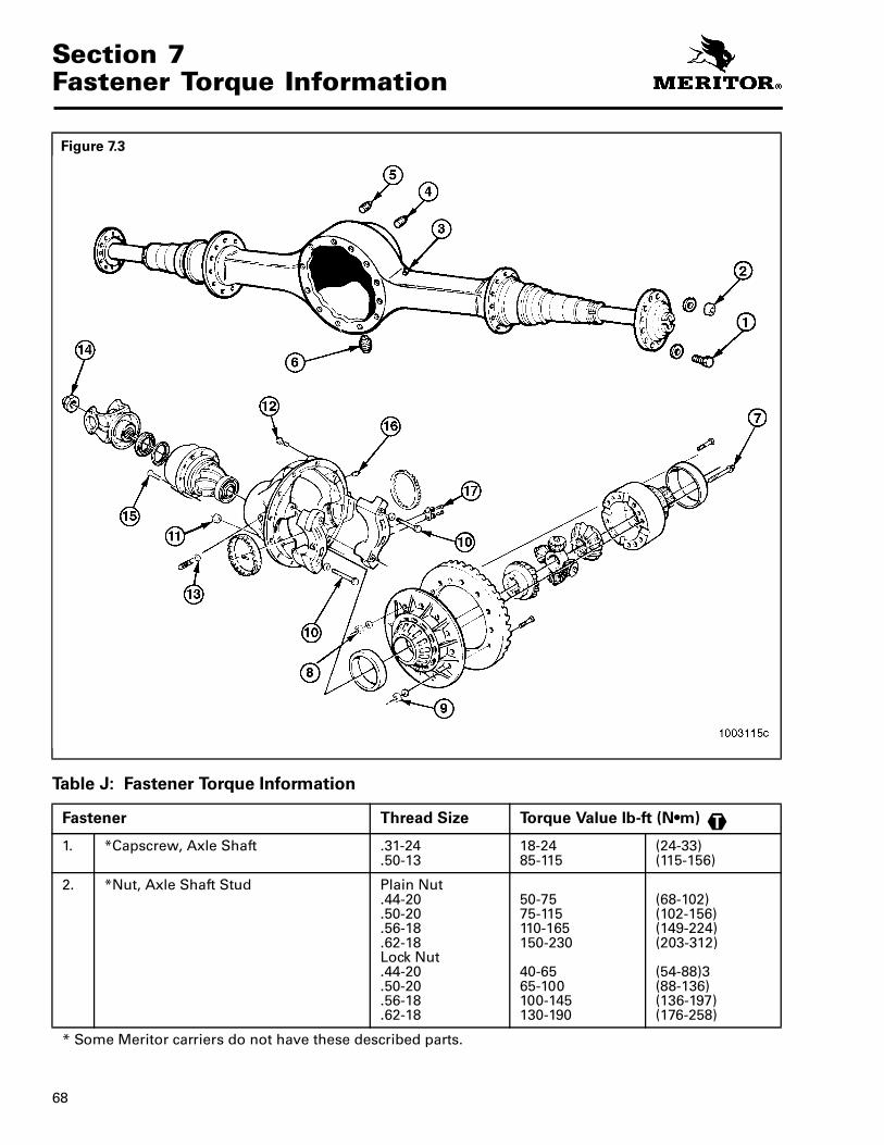
Section 7Fastener Torque Information
68
Table J: Fastener Torque Information
Figure 7.3
Fastener Thread Size Torque Value lb-ft (N•m)
1. *Capscrew, Axle Shaft .31-24.50-13
18-2485-115
(24-33)(115-156)
2. *Nut, Axle Shaft Stud Plain Nut.44-20.50-20.56-18.62-18Lock Nut.44-20.50-20.56-18.62-18
50-7575-115110-165150-230
40-6565-100100-145130-190
(68-102)(102-156)(149-224)(203-312)
(54-88)3(88-136)(136-197)(176-258)
* Some Meritor carriers do not have these described parts.
T
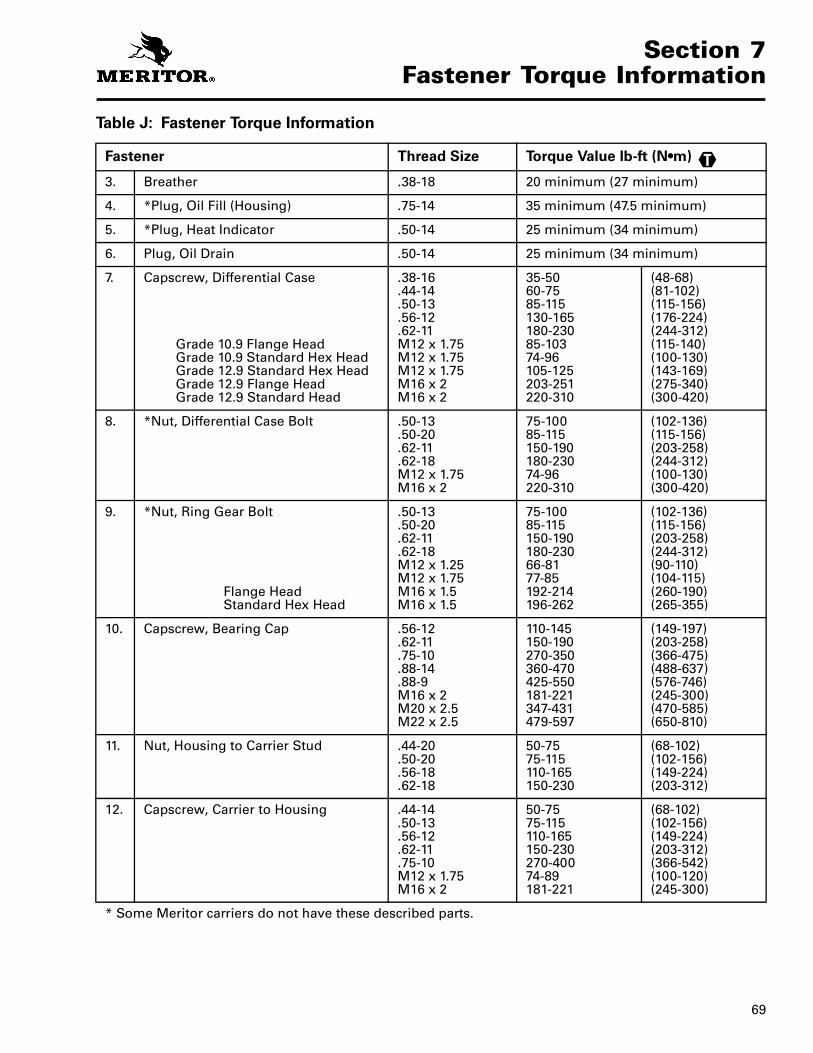
69
Section 7Fastener Torque Information
Table J: Fastener Torque Information
Fastener Thread Size Torque Value lb-ft (N•m)
3. Breather .38-18 20 minimum (27 minimum)
4. *Plug, Oil Fill (Housing) .75-14 35 minimum (47.5 minimum)
5. *Plug, Heat Indicator .50-14 25 minimum (34 minimum)
6. Plug, Oil Drain .50-14 25 minimum (34 minimum)
7. Capscrew, Differential Case
Grade 10.9 Flange HeadGrade 10.9 Standard Hex HeadGrade 12.9 Standard Hex HeadGrade 12.9 Flange HeadGrade 12.9 Standard Head
.38-16
.44-14
.50-13
.56-12
.62-11M12 x 1.75M12 x 1.75M12 x 1.75M16 x 2M16 x 2
35-5060-7585-115130-165180-23085-10374-96105-125203-251220-310
(48-68)(81-102)(115-156)(176-224)(244-312)(115-140)(100-130)(143-169)(275-340)(300-420)
8. *Nut, Differential Case Bolt .50-13.50-20.62-11.62-18M12 x 1.75M16 x 2
75-10085-115150-190180-23074-96220-310
(102-136)(115-156)(203-258)(244-312)(100-130)(300-420)
9. *Nut, Ring Gear Bolt
Flange HeadStandard Hex Head
.50-13
.50-20
.62-11
.62-18M12 x 1.25M12 x 1.75M16 x 1.5M16 x 1.5
75-10085-115150-190180-23066-8177-85192-214196-262
(102-136)(115-156)(203-258)(244-312)(90-110)(104-115)(260-190)(265-355)
10. Capscrew, Bearing Cap .56-12.62-11.75-10.88-14.88-9M16 x 2M20 x 2.5M22 x 2.5
110-145150-190270-350360-470425-550181-221347-431479-597
(149-197)(203-258)(366-475)(488-637)(576-746)(245-300)(470-585)(650-810)
11. Nut, Housing to Carrier Stud .44-20.50-20.56-18.62-18
50-7575-115110-165150-230
(68-102)(102-156)(149-224)(203-312)
12. Capscrew, Carrier to Housing .44-14.50-13.56-12.62-11.75-10M12 x 1.75M16 x 2
50-7575-115110-165150-230270-40074-89181-221
(68-102)(102-156)(149-224)(203-312)(366-542)(100-120)(245-300)
* Some Meritor carriers do not have these described parts.
T

Section 7Fastener Torque Information
70
Table J: Fastener Torque Information
Fastener Thread Size Torque Value lb-ft (N•m)
13. *Jam Nut, Thrust Screw 1.75-161.88-141.12-16M22 x 1.5M30 x 1.5
150-190150-300150-190148-210236-295
(203-258)(203-407)(203-258)(200-285)(320-400)
14. Nut, Drive Pinion 1.88-201.00-201.25-121.25-181.50-121.50-181.75-12M32 x 1.5M39 x 1.5M45 x 1.5
200-275300-400700-900700-900800-1100800-1100900-1200738-918922-1132996-1232
(271-373)(407-542)(949-1220)(949-1220)(1085-1491)(1085-1491)(1220-1627)(1000-1245)(1250-1535)(1350-1670)
15. Capscrew, Bearing Cage .38-16.44-14.50-13.56-12.62-11M12 x 1.75
30-5050-7575-115110-165150-23070-110
(41-68)(68-102)(102-156)(149-224)(203-312)(90-150)
16. *Plug, Oil Fill (Carrier) 1.75-141.5-11.5M24 x 1.5
25 minimum (34 minimum)120 minimum (163 minimum)35 minimum (47 minimum)
17. *Capscrew, Lock Plate .31-18M8 x 1.25
20-3021-26
(27-41)(28-35)
* Some Meritor carriers do not have these described parts.
T

71
Section 8Adjustments and Specifications
Section 8Adjustments and Specifications
Drive Pinion Bearings — Preload (Refer to Section 5)
Drive Pinion — Depth in Carrier (Refer to Section 5)
Hypoid Gear Set — Tooth Contact Patterns (Hand Rolled) (Refer to Section 5)
Main Differential Bearings — Preload (Refer to Section 5)
Specification New bearings
— 5 to 45 lb-in (0.56-5.08 N•m) torque
Used bearings
— 10 to 30 lb-in (1.13-3.39 N•m) torque
Adjustment Preload is controlled by the thickness of the spacer between bearings.
— To increase preload install a thinner spacer
— To decrease preload install a thicker spacer
T
T
Specification Install the correct amount of shims between the bearing cage and carrier. To calculate, use old shim pack thickness and new and old pinion cone numbers.
Adjustment Change the thickness of the shim pack to get a good gear tooth contact pattern.
Specification Conventional gear set
— Toward the toe of the gear tooth and in the center between the top and bottom of the tooth
Generoid gear set
— Between the center and toe of the tooth and in the center between the top and bottom of the tooth
Adjustment Tooth contact patterns are controlled by the thickness of the shim pack between the pinion bearing cage and carrier and by ring gear backlash
— To move the contact pattern lower, decrease the thickness of the shim pack under the pinion bearing cage
— To move the contact pattern higher, increase the thickness of the shim pack under the pinion bearing cage
— To move the contact pattern toward the toe of the tooth, decrease backlash of the ring gear
— To move the contact pattern toward the heel of the tooth, increase backlash of the ring gear.
Specification 15 to 35 lb-in (1.7-3.9 N•m) torque
or
Expansion between bearing caps
— R-140, R-155 and R-160 carrier models — 0.002 to 0.009 inch (0.050-0.229 mm)
— All other carrier models — 0.006 to 0.013 inch (0.150-0.330 mm)
Adjustment Preload is controlled by tightening both adjusting rings after zero end play is reached
T

Section 8Adjustments and Specifications
72
Main Differential Gears — Rotating Resistance (Refer to Section 5)
Ring Gear — Backlash (Refer to Section 5)
Ring Gear — Runout (Refer to Section 5)
Spigot Bearing — Peening on the Drive Pinion (Refer to Section 5)
Specification 50 lb-ft (68 N•m) torque applied to one side gear T
Specification Ring gears that have a pitch diameter of less than 17 inches (431.8 mm)
— Range: 0.008 to 0.018 inch (0.200-0.460 mm)
0.012 inch (0.300 mm) for a new gear set
Ring gears that have a pitch diameter of 17 inches (431.8 mm) or greater
— Range: 0.010 to 0.020 inch (0.250-0.510 mm)
0.015 inch (0.380 mm) for a new gear set
Adjustment Backlash is controlled by the position of the ring gear. Change backlash within specifications to get a good tooth contact pattern.
— To increase backlash, move the ring gear away from the drive pinion
— To decrease backlash, move the ring gear toward the drive pinion
Specification 0.008 inch (0.200 mm) maximum
Specification Apply 6,614 lb (3,000 kg) load on a 0.375 inch or 10 mm ball.
Peen the end of the drive pinion at a minimum of five points.
Softening of the pinion stem end by heating may be required.
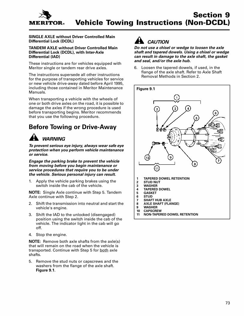
73
Section 9Vehicle Towing Instructions (Non-DCDL)
Section 9Vehicle Towing Instructions (Non-DCDL)SINGLE AXLE without Driver Controlled Main Differential Lock (DCDL)
TANDEM AXLE without Driver Controlled Main Differential Lock (DCDL), with Inter-Axle Differential (IAD)
These instructions are for vehicles equipped with Meritor single or tandem rear drive axles.
The instructions supersede all other instructions for the purpose of transporting vehicles for service or new vehicle drive-away dated before April 1995, including those contained in Meritor Maintenance Manuals.
When transporting a vehicle with the wheels of one or both drive axles on the road, it is possible to damage the axles if the wrong procedure is used before transporting begins. Meritor recommends that you use the following procedure.
Before Towing or Drive-Away
WARNING
To prevent serious eye injury, always wear safe eye protection when you perform vehicle maintenance or service.
Engage the parking brake to prevent the vehicle from moving before you begin maintenance or service procedures that require you to be under the vehicle. Serious personal injury can result.
1. Apply the vehicle parking brakes using the switch inside the cab of the vehicle.
NOTE: Single Axle continue with Step 5. Tandem Axle continue with Step 2.
2. Shift the transmission into neutral and start the vehicle's engine.
3. Shift the IAD to the unlocked (disengaged) position using the switch inside the cab of the vehicle. The indicator light in the cab will go off.
4. Stop the engine.
NOTE: Remove both axle shafts from the axle(s) that will remain on the road when the vehicle is transported. Continue with Step 5 for both axle shafts.
5. Remove the stud nuts or capscrews and the washers from the flange of the axle shaft. Figure 9.1.
CAUTIONDo not use a chisel or wedge to loosen the axle shaft and tapered dowels. Using a chisel or wedge can result in damage to the axle shaft, the gasket and seal, and/or the axle hub.
6. Loosen the tapered dowels, if used, in the flange of the axle shaft. Refer to Axle Shaft Removal Methods in Section 2.
Figure 9.1
1 TAPERED DOWEL RETENTION2 STUD NUT3 WASHER4 TAPERED DOWEL5 GASKET6 STUD7 SHAFT HUB AXLE8 AXLE SHAFT (FLANGE)9 WASHER10 CAPSCREW11 NON-TAPERED DOWEL RETENTION
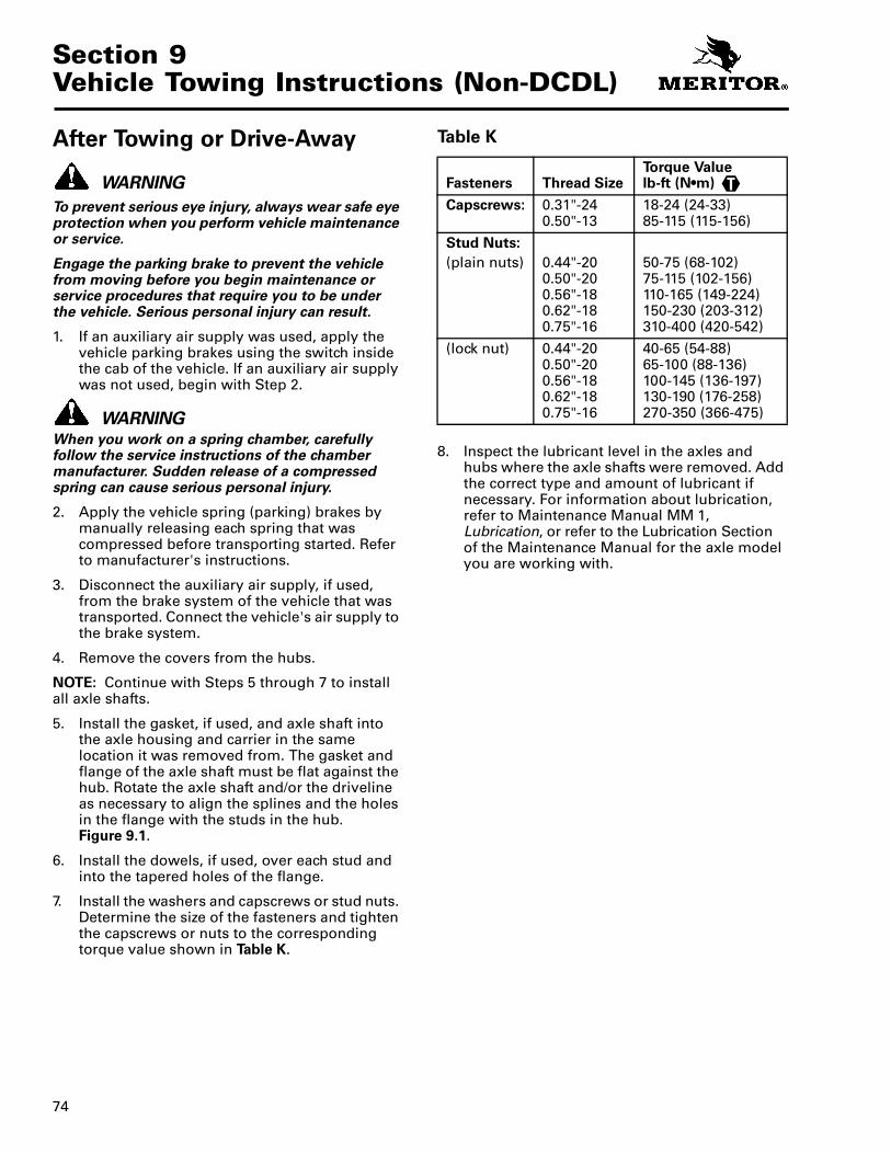
Section 9Vehicle Towing Instructions (Non-DCDL)
74
After Towing or Drive-Away
WARNING
To prevent serious eye injury, always wear safe eye protection when you perform vehicle maintenance or service.
Engage the parking brake to prevent the vehicle from moving before you begin maintenance or service procedures that require you to be under the vehicle. Serious personal injury can result.
1. If an auxiliary air supply was used, apply the vehicle parking brakes using the switch inside the cab of the vehicle. If an auxiliary air supply was not used, begin with Step 2.
WARNINGWhen you work on a spring chamber, carefully follow the service instructions of the chamber manufacturer. Sudden release of a compressed spring can cause serious personal injury.
2. Apply the vehicle spring (parking) brakes by manually releasing each spring that was compressed before transporting started. Refer to manufacturer's instructions.
3. Disconnect the auxiliary air supply, if used, from the brake system of the vehicle that was transported. Connect the vehicle's air supply to the brake system.
4. Remove the covers from the hubs.
NOTE: Continue with Steps 5 through 7 to install all axle shafts.
5. Install the gasket, if used, and axle shaft into the axle housing and carrier in the same location it was removed from. The gasket and flange of the axle shaft must be flat against the hub. Rotate the axle shaft and/or the driveline as necessary to align the splines and the holes in the flange with the studs in the hub. Figure 9.1.
6. Install the dowels, if used, over each stud and into the tapered holes of the flange.
7. Install the washers and capscrews or stud nuts. Determine the size of the fasteners and tighten the capscrews or nuts to the corresponding torque value shown in Table K.
Table K
8. Inspect the lubricant level in the axles and hubs where the axle shafts were removed. Add the correct type and amount of lubricant if necessary. For information about lubrication, refer to Maintenance Manual MM 1, Lubrication, or refer to the Lubrication Section of the Maintenance Manual for the axle model you are working with.
Fasteners Thread SizeTorque Value lb-ft (N•m)
Capscrews: 0.31"-240.50"-13
18-24 (24-33)85-115 (115-156)
Stud Nuts:
(plain nuts) 0.44"-200.50"-200.56"-180.62"-180.75"-16
50-75 (68-102)75-115 (102-156)110-165 (149-224)150-230 (203-312)310-400 (420-542)
(lock nut) 0.44"-200.50"-200.56"-180.62"-180.75"-16
40-65 (54-88)65-100 (88-136)100-145 (136-197)130-190 (176-258)270-350 (366-475)
T

Information contained in this publication was in effect at the time the publication was approved for printing and is subject to change without notice or liability. ArvinMeritor Commercial Vehicle Systems reserves the right to revise the information presented or discontinue the production of parts described at any time.
Copyright Maintenance Manual 5ArvinMeritor, Inc. Revised 10-06All Rights Reserved Printed in the USA
ArvinMeritor, Inc.Commercial Vehicle Systems2135 West Maple RoadTroy, MI 48084 USA800-535-5560www.arvinmeritor.com
2006
16579/22882