Embed Size (px)
Citation preview

Single Photon Interference
Justin Winkler
November 26, 2010
Abstract
Our goal for this lab was to demonstrate the wave-particle duality of light as well as the effects of “whichpath” information on interference experiments. By highly attenuating a collimated laser beam producedby a 5 mW HeNe laser, we were able to observe an example of the wave-particle duality of light using adouble slit apparatus. This was done by imaging the output of the double slit, observing both a graininesscharacterestic of low/single photon detection events and a clear double slit fringe pattern that shows thewave nature of light. Additionally, a Mach-Zehnder interferometer was employed to show the effects of“which path” information by polarizing light in each arm of the polarizer so that light from one arm wasorthogonal to light from the other. We were unable to observe any interference from the interferometerunless we used an analyser polarizer to erase this “which path” information.
1 Background
The nature of light has been a major topic of interest to physics researchers throughout the past centuries. Amajor historical problem was whether light composed of waves or particles. This debate was largely settledin 1803 by Thomas Young [1].
The double slit experiment that Young is famous for demonstrated the wave nature of light. This classicexperiment consists simply of a light source and a sheet with two slits cut in it. Light coming out of the slitsdiffract outward from each slit, and the light from one slit will constructively or destructively interfere withthe light from the other based on the distance from the slits. This leads to an interference pattern, whichis not compatible with a classical particle theory. Utilizing modern technology, this effect is easily seen byshining a collimated laser through a double slit onto a sheet, producing a distinctive fringe pattern that isindicative of constructive and destructive interference.
Figure 1: A sketch made by Thomas Young describing interference from double slit diffraction using waterwaves [2]. The sketch also applies to double slit diffraction using light, illustrating how light waves constructivelyand destructively interfere. Waves diffract from points A and B so that destructive interference occurs at pointsC, D, E, and F, resulting in minima in the fringe pattern.
1

Due to the results of Young’s experiments and subsequent research, the wave theory of light dominateduntil the 20th century. This changed at the turn of the century, where discoveries such as the photoelectriceffect showed that light apparently interacted with matter in only discrete quantities. Based on the photo-electric effect, Albert Einstein developed a model of light whereby light carried energy in discrete packets [3].Such discrete packets of energy were later termed photons by chemist Gilbert Lewis in 1926. Einstein’s modelof light effectively brought a particle theory of light back to the attention of researchers., and the existenceof photons was eventually confirmed through anti-bunching experiments. This aspect of light behaving bothas a wave and a particle is referred to as wave-particle duality.
In modern times, Young’s double slit experiment has become a useful demonstration of the wave-particleduality of light. With current technology, it is possible to create and image single photons. Thus, it is possibleto perform the double slit experiment using a single photon. In this single photon variation, imaging will stilldetect fringe patterns, but they will be built up by multiple photon detections. Even though single photonspass through the slit, interference still occurs. This single photons apparently interferes with itself.
If single photons pass through the double slit apparatus, one might ask “Which slit does the photon passthrough?” This question is apparently unanswerable. The act of observing which slit the photon passesthrough collapses the photons wave function, so that instead of being in a state of superposition betweentwo interfering state, the photon will have a single definite state that cannot interfere with itself. Knowingwhich path the photon takes effectively removes the wave aspect of the photon’s behavior, destroying anyinterference patterns.
The effects of this “which path” information can be seen in any variety of interference based apparatuses,apart from just the double slit experiment. For example, a Mach-Zehnder interferometer produces interfer-ence patterns by splitting a laser down two paths, and then recombining them. Difference in path lengthscause different phases between the two laser beams, leading to interference. If, however, one were to polarizethe light along each path so that the light down one path were an othogonal polarization to the other path,then which path light takes can be readily discerned by these differing polarization. In the process of intro-ducing this which path information, however, the interference pattern will be destroyed. For any interferenceexrperiments, any way to discern the path a particle takes will destroy any interference patterns. In turn, ifthis “which path” information is somehow erased, the interference pattern can be recovered.
2
2 Experimental Setup
We made use of two separate apparatuses for this lab: the double slit apparatus and the Mach-Zehnderinterferometer. Light was supplied to both of these setups from a 5 mW HeNe laser. The laser was collimatedand a non-polarizing beam splitter divided the laser to both setups.
Figure 2: An outline of the double slit apparatus. Light is provided by a 5 mW HeNe laser, and collimatedusing a pinhole and lens. The light passes through the double slit, where the resulting interference pattern maybe observed on a screen or imaged with a CCD camer. Attenuators could be placed on stands located bothbefore and after the double slit. A beam splitter diverts some light to the Mach-Zehnder interferometer (whichotherwise has no bearing on the double slit apparatus).
The double slit apparatus consisted simply of a double slit and attenuators (see figure 2). The doubleslit we used was made on a 2 millimeter thick piece of glass and had a slit width of 10 microns and a slitseparation of 90 microns. A stand was fixed in front of and behind the double slit that allowed us to placemultiple attenuators along the laser path. The laser beam passed through the attenuators and the doubleslit, where the output of the slit could be observed using a screen. The light out of each slit diffracts andinterferes with the light from the other slit, resulting in a multi-fringed interference pattern. A CCD camerawas used to image the resulting interference pattern, particularly when the beam was highly attenuated.
We placed enough attenuators along the beam path so that the rate of photons received by the CCDcamera was quite low. It is worth noting that this does not constitute a single photon source. Even thoughthe average spacing of the photons may be on the order of a meter, one would not be able to obverseantibunching, as instead photons can form multi-photon bunchs. Even though this is not the case of a singlephoton interfering with itself, the photon rate should still be sufficiently low to allow a basic demonstrationof the particle nature of light.
3

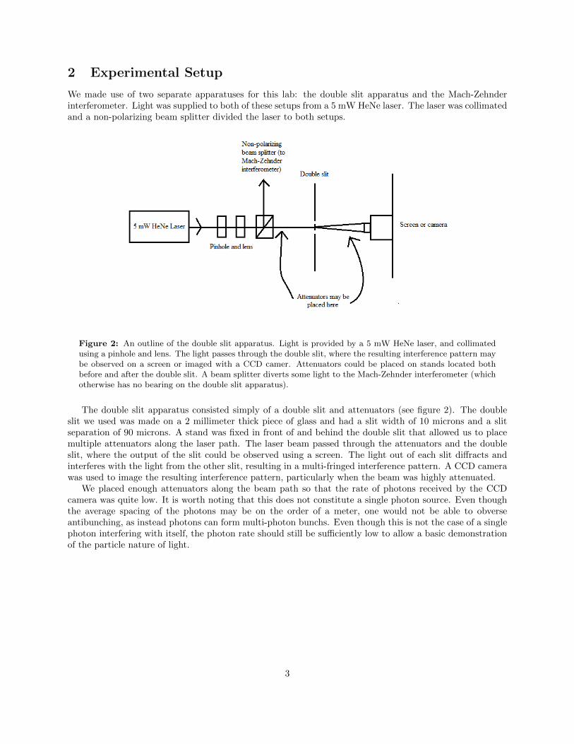
Figure 3: An outline of the Mach-Zehnder interferometer setup. Light is provided from a collimated 5 mWHeNe laser (see figure 2). Attenuators may be placed at the entrance to the interferometer. Light is initiallylinearly polarized by the first polarizer. The incoming light is then split down two paths by a polarizing beamsplitter and subsequently recombined into a single beam with a non-polarizing beam splitter. An analyserpolarizer is placed at the exit of this interferometer and the resulting interference pattern can be viewed on ascreen or imaged with a CCD camera.
The Mach-Zehnder interferometer consisted of a polarizing beam splitter, a non-polarizing beam splitter,attenuators, and a few polarizers and mirrors, and is outlined in figure 2. The collimated laser light waspolarized using a linear polarizer and sent through a polarizing beam splitter. This first polarizer was alignedsuch that the two output beams from the polarizing beam splitter were of equal power. These two polarizedbeams were reflected off mirrors to a non-polarizing beam splitter, aligned so that the output from thenon-polarizing beam splitter was a single beam.
Because the light down each beam have orthogonal polarizations, it is impossible to observe an interferencepattern outright because of the presence of which way information. To rectify this, an analyser polarizer isplaced at the output of the second beam splitter. If the polarizer is aligned 45◦ to the polarization of thetwo beams, the polarizer erases the which way information (as light coming out of the beam splitter willonly have a single polarization), causing the appearance of an interference pattern [4].
4

3 Procedure and Results
The first experiment we performed was a demonstration of the wave-particle duality of light. This experimentmade use of the double slit apparatus.
Figure 4: An image taken of the fringe pattern produced by the double slit apparatus with 4 orders ofmagnitude of attenuation. This image was taken using a CCD camera with a 0.1 second exposure time and nogain, with the brightness of the image subsequently inverted. The overarching structure of this image matchesthe structure expected from double slit diffraction. There is some fine structure evident in the large centraldarker band and extra thin dark bands present throughout the other bands. This fine structure is caused byreflection of light from the glass slit and its diffraction with a double slit interference wave.
The first step in using the double slit apparatus was confirmation of the interference pattern. This wasdone by only attenuating the laser beam by 4 orders of magnitude (enough to keep the camera safe) andimaging the output of the double slit with a CCD camera. The image observed is displayed in figure 4.Note that while the fringes primarily follow the classic double slit pattern of evenly spaced, roughly equalamplitude fringes, there is some fine structure fringing resulting from reflection off of the glass double slit.We expected all subsequent images of the double slit pattern to have the same structure as seen in figure 4.
We chose 4 orders of magnitude of attenuation for initial imaging because this corresponds roughly to anaverage separation between photons of 1 meter. This is calculated using the formula
N
d=Pλ
hc2
where P is the laser power, λ = 632.8 nm is the wavelength of the HeNe laser, h is Planck’s constant, c isthe speed of light, and N/d gives the average number of photons per unit distance. We measured the poweroutput from the double slit to be 1 µW without any attenuators, so 4 orders of magnitude correspond to apower output of 100 pW, yielding an average photon separation of 0.936 meters.
5

(a) 0.5 seconds exposure time (b) 1 second exposure time (c) 5 second exposure time
Figure 5: Images of double slit output taken using an attenuation of 0.8 × 10⁻⁵. Gain was at 255 and eachimage is contrast adjusted and brightness inverted. Exposure times were, from left to right, 0.5 seconds, 1second, and 5 seconds. These images provide an example of how the fringe pattern is built up over time asmore photons are detected. At a 0.5 second exposure time, the detections are largely scattered, but structureis clearly seen to take shape at 1 second exposure time, and the fringe structure seen in figure 4 is clearlyreproduced when using a 5 second exposure time.
This experiment was then repeated using various levels of attenuation. Figure 5 shows some of the finerquality images taken at an attenuation of 0.8 × 10⁻⁵. This level of attenuation was the highest level ofattenuation at which we could reliably image, and corresponds to an average photon separation of 11.7meters. At this amount of attenuation, the camera detects photons at a relatively slow rate (about 25.6million per second). As the exposure time increases, the fringe structure seen in figure 4 gradually becomesevident. Thus, while the camera is detecting photons at a very low rate, the photons are limited to detectionin regions consistent with the double slit diffraction interference pattern. This is an excellent example ofthe wave-particle duality of light, as the light is apparently displaying particle like behavior in the way it isdetected, but the interference pattern can only be accounted by wave-like behavior.
6

(a) Analyser polarizer at 45◦ (b) Profile of 45◦ image
(c) Analyser polarizer at 90◦ (d) Profile of 90◦ image
Figure 6: Images of Mach-Zehnder interferometer output taken using an attenuation of 4 orders of magnitude.Camera was set to no gain, 0.1 second exposure time, and the image brightness was subsequently inverted.Image (a) shows a typical interference pattern. Which way information is not present in (a) because thepolarizer is aligned at 45◦, allowing for interference to occur. Image (c) has no interference pattern becausethe polarizer is set only to pass light from a certain arm (90◦ polarization). Which path information is alwaysgained at the expense of destroying any interference pattern. The ring pattern present in both images is likelycaused by water trapped in the againg camera’s lens, or dirt on one of the interferometer mirrors. Images (b)and (d) provide sample profiles taken from images (a) and (c) respectively.
The second experiment was a demonstration of the effect of which path information using the Mach-Zehnder interferometer. The leading polarizer was aligned so that the power in each arm of the interferometerwas equivalent (measured at 0.123 mW in each arm).
As before, we first performed our experiment with relatively little attenuation. We imaged the outputof the interferometer using a few different analsyer polarizer alignments. A couple of examples of theobserved images are seen in figure 6, and provides a basic example of the interference pattern seen from theMach-Zehnder interferometer. The images in 6 are characterisic of the effects of which path information,demonstrating that, in the process of gaining which path information, interference is destroyed.
7

(a) 175◦ (b) 185◦ (c) 195◦ (d) 205◦
(e) 215◦ (f) 225◦ (g) 235◦ (h) 245◦
(i) 255◦ (j) 265◦ (k) 275◦ (l) 285◦
Figure 7: Images of Mach-Zehnder interferometer output taken using an attenuation of 7 orders of magnitude.The camera was set to use 255 gain and a 1 second exposure time, with the image brightness subsequentlyinverted. The images were taken for different analyser polarizer angles, varying by 10◦ from 175◦ to 285◦.Bordered images indicate that which path information was present.
Imaging of the interference at different analyser polarizer angles was subsequently repeated using higherlevels of attenuation and a larger number of polarizer alignments. Figure 7 provides an example of how theanalyser polarizer alters the interference pattern. Which path information is present when the polarizer isaligned to 175◦ and 265◦, so these angles yield no interference. The intermediate angles yield varying degreesof fringe visibility based on how close close the polarizer is to the angles that yield which path information.Thus, figure 7 serves as a good demonstration of how interference is destroyed when which path informationis gained.
A more quantitative analysis can be done relying on fringe visibility. Fringe visibility is described usingthe formula:
8

V isibility =Max−Min
Max+Min
where max and min describe the maximum and minumum intensity values of the fringe pattern. In theory, theMach-Zehnder interferometer should give a sinusoidal fringe pattern with constant maximum and minimumintensities. This does not occur in practice due to noise from ambient light and higher order interferenceeffects. The pattern actually observed is quite noisy, as can be seen in the cross-sections shown in figure 6.This makes measuring fringe visibility a challenge. This issue was addressed by simply fitting a sine functionto the observed data and measuring the fringe visibility of the fit function.
From figure 7, there are approximately 24 fringes in a 512 pixel region. As such, the frequency of thefringe pattern was approximated to 24/512. Mathematica was then used to find a fit for a cross section ofthe pixel intensities for each image. The fit function was of the form a+b∗Sin( 24∗2π∗x
512 +c), with x being theindependent variable and a, b, and c being parameters determined by the fit algorithm. The fringe visibilitycan be found from the determined parameters of the fit as b/a. While this approach may not be a perfectmeasure of fringe visibility, it gives a decent estimate and demonstrates quantitatively how the polarizationangle affects the fringe pattern.
Figure 8: A plot of the fringe visibility against the polarization angle, with data taken from table 1.
9

Angle Of Polarization Fringe Visibility
135◦ 0.147145◦ 0.119155◦ 0.090165◦ 0.055175◦ 0.007185◦ 0.015195◦ 0.074205◦ 0.090215◦ 0.121225◦ 0.049235◦ 0.141245◦ 0.093255◦ 0.049265◦ 0.017275◦ 0.023285◦ 0.061295◦ 0.072305◦ 0.095315◦ 0.107
Table 1: The full range of polarization angles used for imaging and the fringe visibilities found at eachpolarization angle. A selection of the images corresponding to the different polarization angles are displayedin figure 7. There were 7 orders of attenuation, and the camera was set to 1 second acquisition time with 255gain.
Table 1 shows the fringe visibility values found using the approach outlined above, using the full range ofimaged polarization angles. These values are plotted in figure 8. We expect minima at polarization angles180◦ and 270◦ when which-path information is present and maxima at 135◦, 225◦, and 315◦ when no suchinformation is present. This is roughly confirmed in figure 8, with the rather noticeable exception at thepolarization angle 225◦, an outlier against the apparent pattern.
10

Figure 9: A plot of the fringe visibility against the acquistion time, with 4 orders of attenuation, polarizationset to 135◦, and the camera set to no gain.
Some final analysis is of how visibility is affected by the amount of time the camera spends in acquiringan image. We set up the apparatus to allow for much brighter fringes, with attenuation at only 4 orders ofmagnitude and the polarization angle at 135◦, a maxima in figure 8. The camera was set to no gain and itsacquistion time was varied to produce a few different images. The observed fringe visibilities (found usingthe same approach as used above) are plotted in figure 9. We would expect that higher acquistion timeswould lead to a higher signal to noise ratio, thereby improving visibility, and this is apparently confirmed infigure 9. Higher acquisition times lead to higher fringe visibility values.
4 Conclusion
In this lab, we have provided a simple demonstration of the wave-particle duality of light through usageof a double slit apparatus. In imaging the output of the double slit apparatus, the graininess of highlyattenuated laser beams is indicative of discrete photons that are apparently striking the camera at a relativelylow frequency. Even with such a low photon rate, however, fringe patterns are still observed, built up bythe camera in discrete photon detections over an extended exposure time. Thus photons are evidentallyinterfering with themselves despite their large average spacing. This imaging of discrete light detectionevents following an intereference pattern is a pithy demonstration of the wave-particle duality of light.
The Mach-Zehnder interferometer allowed further exploration of the nature of the double slit experimentand other interference experiments with regards to “which path” information. By polarizing the light ineach arm of the Mach-Zehnder interferometer, it was possible to determine which path light came from,but this also made interference impossible. Only by using an additional polarizer to erase the “which path”information were we able to again observe interference. There are a wide variety of ways of obtaining “whichpath” information in interference experiments, but the act of obtaining this information always preventsinterference from occuring. The Mach-Zehnder setup we used provided a basic example of this phenomena,as well as serving as a basic demonstration of how “which path” information can be erased to restoreinterference.
11

References
[1] T. Young, Experiments and Calculations Relative to Physical Optics, Proc. Roy. Soc. Long. A 94 (1804),1-16.
[2] T. Young, Course of Lectures on Natural Philosophy and the Mechanical Arts, 1807
[3] Einstein, Albert (1905). “Uber einen die Erzeugung und Verwandlung des Lichtes betreffenden heuris-tischen Gesichtspunk”. Annalen der Physik 17: 132148.
[4] M.B. Schneider and I.A. LaPuma, Am. J. Phys., 70 (3), 266-271 (2002).
12