Embed Size (px)
Citation preview

AB20023, Rev 811/20
single & tAndem Axle spRAyeR500 gallon

Page 2 AB20023
Thank you for purchasing a Demco sprayer. We feel you have made a wise choice and hope you are completely satisfied with your new sprayer. If you have any questions regarding the applications of certain solutions or chemicals, contact your chemical supplier and follow chemical manufacturer recommendations as well as all licensing and use restrictions or regulations.
1. Unless otherwise specified, high-strength (grade5) (3 radial-line head markings) hex head bolts are used throughout assembly of this sprayer.
2. Whenever terms “LEFT” and “RIGHT” are used in this manual it means from a position behind sprayer and facing forward.
Chemicals are dangerous. Know exactly what you’re going to do and what is going to happen before attempting to work with these products. Improper selection or use can injure people, animals, plants and soil.
Always wear protective clothing such as coveralls, goggles and gloves when work-ing with chemicals or sprayer.
Be sure to dispose of all unused chemicals or solutions in a proper and ecologically sound manner.
TeeJet is a registered trademark of Spraying Systems Company
3. When placing a parts order, refer to this manual for proper part numbers and place order by PART NO. and DESCRIP-TION.
General Information ................................................................................................................... 2 Warranty Registration ...............................................................................................................3-4 Safety Information .....................................................................................................................5-6 Safety Sign Locations ................................................................................................................. 7 Safety Information Continued ................................................................................................8-12 Bolt Torque ................................................................................................................................. 13 Single Axle Assembly ............................................................................................................... 14 Tandem Wheel Carrier ............................................................................................................. 15 Tongue and Weight Box Assembly ......................................................................................... 16 Step And Platform Assembly ................................................................................................... 17 Boom Carrier, Safety Stand and Tank Assembly ................................................................ 18-19 Main Parts Break Down .......................................................................................................... 20-21 Gear Pump Mounting ............................................................................................................... 22 Belt Drive and Hydraulic Pump Mounting ............................................................................. 23 Centrifugal Pump Plumbing ................................................................................................. 24-25 Pump Start-up Instructions ....................................................................................................... 26 DFS55 Flush Assembly .......................................................................................................... 27-28 Quick Refill and Foam Marker ................................................................................................. 29 Sprayer Checklist ....................................................................................................................... 30
WARRAnty pOliCy, OpeRAtOR mAnUAls & RegistRAtiOnGo online to www.demco-products.com to review Demco warranty policies, operator manuals and register your Demco product.
intROdUCtiOn
WARNING: TO AvOID PERSONAL INjuRy OR PROPERTy DAmAGE, OBSERvE FOLLOWING INSTRuCTIONS:
geneRAl inFORmAtiOn
tABle OF COntents signAl WORds:

AB20023 Page 3
TAKE NOTE! THIS SAFETy ALERT SymBOL FOuND THROuGHOuT THISmANuAL IS uSED TO CALL yOuR ATTENTION TO INSTRuCTIONS INvOLvING yOuR PERSONAL SAFETy AND SAFETy OF OTHERS. FAILuRE TO FOLLOW THESE INSTRuCTIONS CAN RESuLT IN INjuRy OR DEATH!
THIS SymBOL mEANS
ATTENTION
BECOmE ALERT
yOuR SAFETy IS INvOLvED!
dAngeR: Indicates an imminently hazardous situation that, if not avoided, will result in death or serious injury. This signal word is to be limited to most extreme situations typically for machine components which, for functional purposes, cannot be guarded.
WARning: Indicates a potentially hazardous situation that, if not avoided, could result in death or serious injury, and includes hazards that are exposed when guards are removed. It may also be used to alert against unsafe practices.
CAUtiOn: Indicates a potentially hazardous situation that, if not avoided, may result in minor or moderate injury. It may also be used to alert against unsafe practices.
If you have questions not answered in this manual, require additional copies, or if your manual is damaged, please contact your dealer or Demco, 4010 320th Street, Boyden, IA 51234
ph: (712) 725-2311 or Toll Free: 1-800-543-3626 Fax: (712) 725-2380http://www.demco-products.com
signAl WORds: This manual uses the following signal words--DANGER, WARNING, and CAUTION-- with safety messages. The appropriate signal word has been selected using the following guidelines.
sAFety

Page 4 AB20023
Every year many accidents occur which could be avoided by a few seconds of thought and more careful approach to handling equipment. You, the operator, can avoid accidents by observing precautions in this section. To avoid personal injury, study precautions and insist those working with you, or you yourself, follow them.
In order to provide a better view, certain illustrations in this manual may show an assembly with a safety shield removed. However, sprayer should never be operated in this condition. Keep all shields in place. If shield removal becomes necessary for repairs, replace shield prior to use.
Replace any caution, warning, danger or instruction safety decal that is not readable or is missing. Location of such decals is indicated in this booklet.
Do not attempt to operate this sprayer under the influence of alcohol or drugs.
Review safety instructions with all users.
Operator should be a responsible adult. DO NOT ALLOW PERSONS TO OPERATE OR ASSEmBLE THIS SPRAyER uNTIL THEy HAvE DEvELOPED A THOROuGH uNDERSTANDING OF SAFETy PRECAuTIONS AND HOW IT WORKS.
To prevent injury or death, use a tractor equipped with a roll over protective system (ROPS). Do not paint over, remove, or deface any safety signs or warning decals on your sprayer. Observe all safety signs and practice instructions on them.
Never exceed limits of sprayer. If its ability to do a job, or to do so safely is in questionDON’T TRy IT.
It is the responsibility of operator to know lighting and marking requirements of local highway authorities and to install and maintain equipment to provide compliance with regulations. Add extra lights when transporting at night or during periods of limited visibility.
Lighting kits are available from your dealer or manufacturer.
sAFety...yOU CAn live With it
sAFety
eqUipment sAFety gUidelines
lighting And mARking

AB20023 Page 5
Types of safety sign and locations on equipment are shown in illustration below. Good safety requires that you familiarize yourself with various safety signs, type of warning, and area or particular function related to that area, that requires your SAFETY AWARENESS.
WARNING To prevent serious injury or death
• Refer to chemical supplier and manufacturer recommendations and all licensing restrictions or regulations.
• Always wear recommended protective clothing when working with chemicals or sprayer.
• Dispose of all unused chemicals or solutions in proper and ecologicallysound manner. Improper use can injure people, animals, plants and soil.
REV 1 AB21014
WARNING
To prevent serious injury ordeath.
Do not ride or stand on sprayerwhile any part of sprayer ismoving.
Keep riders off at all times.
REV 1 AB21001
CAUTION!
Do not exceed 20 MPHwhen loaded.
09/99 AG21002
NOTICE!Keep wheel lug nuts or bolts tightened to specified torque
IMPORTANT:Always retorque wheels after first trip!
Tire size
P295 or 11.00 X 22.5 P385 or 15.00 X 22.5 P425 or 16.5 X 22.5 P445 or 18.00 X 22.5
CAUTION:Over inflation may result in damage to running gear and box integrity.
REV 3 AG21001
650bu.3/4”-16UNF Grade 8
Torque to 400 ft. lbs.
450/550bu.5/8”-18UNF Grade 8Torque to 225 ft. lbs.
Check tire pressure regularly.
365bu. 5/8”-18UNF Grade 5Torque to 150 ft. lbs.
Nut or Bolt Torques Tire Pressure365/450 bu. 550/650bu.45-55 psi. NA40-50 psi. NA35-45psi. 50-60 psi.NA 45-55 psi.
AB
C
D
E
DANGER
Do not operate without• All driveline guards, tractor and equipment shields in place.• Drivelines securely attached at both ends.• Driveline guards that turn freely on driveline.
AA21059
Contact with Rotating Drivelinewill cause serious injury or death.
REV 1
A. Side of Frame AG21002 Qty.1
B. PTO Shaft AA21059 Qty. 1
C. Side of Frame AB21001 Qty. 1E. Side of Frame AG21001 Qty. 1
D. Top of Tank AB21014 Qty. 1
sAFety sign lOCAtiOns
sAFety

Page 6 AB20023
• Keepsafetysignscleanandlegibleatalltimes.
• Replacesafetysignsthataremissingorhavebecomeillegible.
• Replacementpartsthatdisplayedasafetysignshouldalsodisplaycurrentsign.
• Safetysignsareavailablefromyourdistributor,dealerpartsdepartment,ormanufacturer.
How to install safety signs:
• Besureinstallationareaiscleananddry.
• Decideonexactpositionbeforeyouremovebackingpaper.
• Removesmallestportionofsplitbackingpaper. • Aligndecaloverspecifiedareaandcarefullypresssmallportionwith exposed sticky backing in place.
• Slowlypeelbackremainingpaperandcarefullysmoothremainingportionofdecalintoplace.
• Smallairpocketscanbepiercedwithapinandsmoothedoutusingpieceofdecalbackingpaper.
• Failuretofollowproperprocedureswhenmountingtireonrimcanproduceanexplosionresulting in serious injury or death.
• Donotattempttomounttireunlessyouhaveproperequipmentandexperience.
• Inflatingorservicingtirescanbedangerous.Wheneverpossible,trainedpersonnelshouldbe called to service or mount tires.
• Alwaysorderandinstalltiresandwheelswithappropriatetypeandloadcapacitytomeetorexceed anticipated weight to be placed on sprayer.
Your best assurance against accidents is a careful and responsible operator. If there is any portion of this manual or function you do not understand, contact your local authorized dealer or manufacturer.
• Carefullystudyandunderstandthismanual.
• Donotwearloose-fittingclothingwhichmaycatchinmovingparts.
• Alwayswearprotectiveclothingandsubstantialshoes.
• Itisrecommendedthatsuitablehearingandeyeprotectionbeworn.
• Operatormaycomeincontactwithcertainmaterialswhichmayrequirespecific safety equipment relative to handling of such materials. (Examples: extremely dusty, molds, fungus, bulk fertilizers, etc.)
sAFety sign CARe
sAFety
tiRe sAFety
RememBeR
BeFORe OpeRAtiOn

AB20023 Page 7
• Keepwheelandlugnutstightenedtospecifiedtorque.
• Assurethatagriculturalimplementtiresareinflatedevenly.
• Givesprayeravisualinspectionforanyloosebolts,wornparts,orcrackedwelds,andmakenecessary repairs. Follow maintenance safety instructions included in this manual.
• Besuretherearenotoolslyingonorinequipment
• Donotusethesprayeruntilyouaresurethatareaisclear,especiallyaroundchildrenandanimals.
• Don’thurrylearningprocessortakesprayerforgranted.Easeintoitandbecomefamiliarwithyour new equipment.
• Practiceoperationofyoursprayeranditsattachments.Completelyfamiliarizeyourselfandother operators with its operation before using.
• UseatractorequippedwithRollOverProtectionSystem(ROPS)andfastenyourseatbeltpriorto starting engine.
• ManufacturerdoesnotrecommendusageoftractorwithROPSremoved.
• Movetractorwheelstowidestrecommendedsettingstoincreasestability.
• Donotallowanyonetostandbetweentongueorhitchandtowingunitwhenbackinguptoequipment.
• Bewareofbystanders,PARTICuLARLy CHILDREN! Always look around to make sure it is safe to start engine of towing unit or move sprayer. This is particularly important with higher noise levels and quiet cabs, as you may not hear people shouting. • NOPASSENGERSALLOWED- Do not carry passengers anywhere on or in the tractor or sprayer.
• Keephandsandclothingclearofmovingparts.
• Donotclean,lubricate,oradjustyoursprayerwhileitismoving.
• Whenhaltingoperation,evenperiodically,settractorortowingunitbrakes,disengagePTO,shutoffengine, and remove ignition key.
• Beespeciallyobservantofoperatingareaandterrain-watchforholes,rocks,orotherhiddenhazards. Always inspect area prior to operation.
- DO NOT operate near edge of drop-offs or banks.
- DO NOT operate on steep slopes as overturn may result.
- Operate up and down (not across) intermediate slopes. Avoid sudden starts and stops.
dURing OpeRAtiOn

Page 8 AB20023
• Pickthemostlevelpossibleroutewhentransportingacrossfields.Avoidedgesofditches,gullies,andsteep hillsides.
• Beextracarefulwhenworkingoninclines.
• Periodicallyclearequipmentofbrush,twigs,orothermaterialstopreventbuildupofdrycombustible materials.
• Maneuvertractorortowingunitatsafespeeds.
• Avoidoverheadwiresorotherobstacles.Contactwithoverheadlinescouldcauseseriousinjuryordeath.
• Avoidloosegravel,rocks,andholes;theycanbedangerousforequipmentoperationormovement.
• Allowforsprayerlengthwhenmakingturns.
• Donotwalkorworkunderraisedcomponentsorattachmentsunlesssecurelypositionedandblocked.
• Keepallbystanders,pets,andlivestockclearofworkarea.
• Operatetowingunitfromoperatorsseatonly.
• Neverstandalongsideofunitwithenginerunningorattempttostartengineand/oroperatemachinewhile standing alongside of unit.
• Neverleaverunningequipmentattachmentsunattended.
• Asaprecaution,alwaysrecheckhardwareonequipmentfollowingevery100hoursofoperation.Correct all problems. Follow maintenance safety procedures.
• Followingoperation,orwhenunhitching,stoptractorortowingunit,setbrakes,disengagePTOandall power drives, shut off engine and remove ignition key.
• Storesprayerinanareaawayfromhumanactivity.
• Donotparksprayerwhereitwillbeexposedtolivestockforlongperiodsoftime.Damageandlivestock injury could result.
• Donotpermitchildrentoplayonoraroundthestoredsprayer.
• Makesureallparkedmachinesareonahard,levelsurfaceandengageallsafetydevices.
• Wheelchocksmaybeneededtopreventunitfromrolling.
sAFety
FOllOWing OpeRAtiOn

AB20023 Page 9
• Watchforobstructionsoverheadandsidetosidewhiletransporting.
• Alwaysoperateequipmentinapositiontoprovidemaximumvisibilityatalltimes.Makeallowancesforincreased length and weight of sprayer when making turns, or stopping.
• SAFETy CHAINS: If equipment is going to be transported on a public highway, always follow state and local regula-tions regarding safety chains and auxiliary lighting. Be sure to check with local law enforcement agencies for your own particular regulations. If required safety chains should be obtained and installed. Only safety chains (not elastic or nylon/plastic tow straps) should be used to retain connection between towing and towed machines in event of separation of primary attaching system. Use a high strength, appropriately sized hitch pin with a mechanical retainer and attach safety chains. Criss cross chains under tongue and secure to draw bar cage, mounting loops, or bumper frame.
• Adoptsafedrivingpractices:
- Keep brake pedals latched together at all times. NEvER uSE INDEPENDENT BRAKING WITH SPRAyER IN TOW. LOSS OF CONTROL OR uPSET mAy RESuLT.
- Always drive at a safe speed relative to local conditions and ensure that your speed is low enough for an emergency stop. Keep speed to a minimum.
- Reduce speed prior to turns to avoid risk of overturning.
- Always keep tractor or towing unit in gear to provide engine braking when going downhill. Do not coast.
- Do not drink and drive!
• Complywithstateandlocallawsgoverninghighwaysafetyandmovementoffarmmachineryonpublicroads.
• Useapprovedaccessorylightingflagsandnecessarywarningdevicestoprotectoperatorsofothervehiclesonhighwayduring transport. Various safety lights and devices are available from your dealer.
• Useofflashingamberlightsisacceptableinmostlocalities.However,somelocalitiesprohibittheiruse.Local lawsshould be checked for all highway lighting and marking requirements.
• Whendrivingtractorandsprayerunder20mph(40kph)dayornight,useflashingamberwarninglightsandaslowmoving vehicle (SMV) identification emblem.
• Planyourroutetoavoidheavytraffic.
• Beasafeandcourteousdriver.Alwaysyieldtooncomingtrafficinallsituations,includingnarrowbridges,intersections,etc.
• Beobservantofbridgeloadratings.Donotcrossbridgesratedlowerthangrossweightofunityouareoperating.
• Watchforobstructionsoverheadandsidetosidewhiletransporting.
• Alwaysoperateequipmentinapositiontoprovidemaximumvisibilityatalltimes.Makeallowancesforincreasedlengthand weight of sprayer when making turns, or stopping.
highWAy And tRAnspORt OpeRAtiOns
sAFety

Page 10 AB20023
• Goodmaintenanceisyourresponsibility.Poormaintenanceisaninvitationtotrouble.
• Makesure there isplentyof ventilation.Neveroperateengineof towingvehicle inaclosedbuilding. Exhaust fumes may cause asphyxiation.
• Beforeworkingon thismachine, stop towingvehicle, setbrakes,disengagePTOandallpowerdrives, shut off engine and remove ignition key.
• Becertainallmovingpartsandattachmentshavecometoacompletestopbeforeattemptingto perform maintenance.
• Always use a safety support and block wheels. Never use a jack to support machine.
• Alwaysusepropertoolsorequipmentforjobathand.
• Useextremecautionwhenmakingadjustments.
• Followtorquechartinthismanualwhentighteningboltsandnuts.
• Neveruseyourhandstolocateahydraulicleakonattachments.Useasmallpieceofcardboardor wood. Hydraulic fluid escaping under pressure can penetrate skin.
• Openingsinskinandminorcutsaresusceptibletoinfectionfromhydraulicfluid. Without immediate medical treatment, serious infection and reactions can occur.
• Whendisconnectinghydrauliclines,shutoffhydraulicsupplyandrelieveallhydraulicpressure.
• Replaceall shields and guards after servicing and before moving.
• Afterservicing,besurealltools,partsandserviceequipmentareremoved.
• Donotallowgreaseoroiltobuilduponanystepsorplatform.
• Whenreplacingboltsrefertoownersmanual.
• Refertobolttorquechartforheadidentificationmarking.
• Wherereplacementpartsarenecessaryforperiodicmaintenanceandservicing,genuinefactory replacement parts must be used to restore your equipment to original specifications. Manufacturer will not claim responsibility for use of unapproved parts or accessories and other damages as a result of their use.
• Ifequipmenthasbeenalteredinanywayfromoriginaldesign,manufacturerdoesnotacceptany liability for injury or warranty.
• Afireextinguisherandfirstaidkit shouldbekept readilyaccessiblewhileperformingmaintenanceon this equipment
peRFORming mAintenAnCe
sAFety
AB20023 Page 11
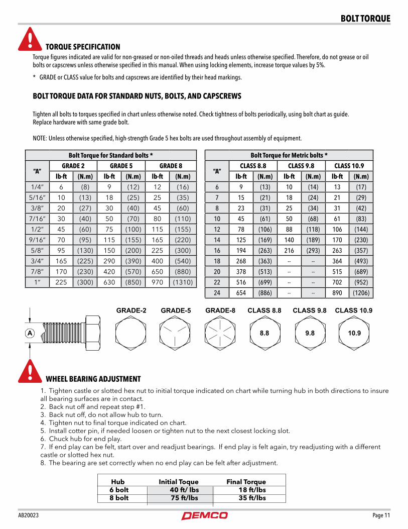
1. Tighten castle or slotted hex nut to initial torque indicated on chart while turning hub in both directions to insure all bearing surfaces are in contact.2. Back nut off and repeat step #1.3. Back nut off, do not allow hub to turn.4. Tighten nut to final torque indicated on chart.5. Install cotter pin, if needed loosen or tighten nut to the next closest locking slot.6. Chuck hub for end play.7. If end play can be felt, start over and readjust bearings. If end play is felt again, try readjusting with a different castle or slotted hex nut.8. The bearing are set correctly when no end play can be felt after adjustment.
Hub Initial Toque Final Torque 6 bolt 40 ft/ lbs 18 ft/lbs 8 bolt 75 ft/lbs 35 ft/lbs
BOlt tORqUe
tORqUe speCiFiCAtiOnTorque figures indicated are valid for non-greased or non-oiled threads and heads unless otherwise specified. Therefore, do not grease or oil bolts or capscrews unless otherwise specified in this manual. When using locking elements, increase torque values by 5%.
* GRADE or CLASS value for bolts and capscrews are identified by their head markings.
BOlt tORqUe dAtA FOR stAndARd nUts, BOlts, And CApsCReWs
Tighten all bolts to torques specified in chart unless otherwise noted. Check tightness of bolts periodically, using bolt chart as guide. Replace hardware with same grade bolt.
NOTE: Unless otherwise specified, high-strength Grade 5 hex bolts are used throughout assembly of equipment.
Bolt torque for standard bolts *
“A”gRAde 2 gRAde 5 gRAde 8
lb-ft (n.m) lb-ft (n.m) lb-ft (n.m)
1/4” 6 (8) 9 (12) 12 (16)
5/16” 10 (13) 18 (25) 25 (35)
3/8” 20 (27) 30 (40) 45 (60)
7/16” 30 (40) 50 (70) 80 (110)
1/2” 45 (60) 75 (100) 115 (155)
9/16” 70 (95) 115 (155) 165 (220)
5/8” 95 (130) 150 (200) 225 (300)
3/4” 165 (225) 290 (390) 400 (540)
7/8” 170 (230) 420 (570) 650 (880)
1” 225 (300) 630 (850) 970 (1310)
Bolt torque for metric bolts *
“A”ClAss 8.8 ClAss 9.8 ClAss 10.9
lb-ft (n.m) lb-ft (n.m) lb-ft (n.m)
6 9 (13) 10 (14) 13 (17)
7 15 (21) 18 (24) 21 (29)
8 23 (31) 25 (34) 31 (42)
10 45 (61) 50 (68) 61 (83)
12 78 (106) 88 (118) 106 (144)
14 125 (169) 140 (189) 170 (230)
16 194 (263) 216 (293) 263 (357)
18 268 (363) -- -- 364 (493)
20 378 (513) -- -- 515 (689)
22 516 (699) -- -- 702 (952)
24 654 (886) -- -- 890 (1206)
Wheel BeARing AdJUstment

Page 12 AB20023
1. Begin by resting the frame (#1) on sawhorses or solid object so frame is about 36” off the ground.
2. Fasten undercarriage (#2) to frame using 1/2” x 1-1/4” bolts (#3) with flatwashers (#4) and nylon locknuts (#5).
3. Slide axle (#6) into position on each side for your particular wheel spacing.
4. Secure Slide-In Axle (#6) with Axle clamp (#7) two 3/8” x 2” bolts (#8) and nylon locknuts (#9).
5. Bolt two rims with tires mounted (#10) to hubs (#11) with lugnuts (#12).
AXLE ASSEmBLy INSTRuCTIONS
1210
11
84
9
2
5
1
43
64
7
single Axle AssemBly

AB20023 Page 13
18
19
8
4
9
2
5
1
43
6
4
7
13
15
16
14
10
12
1. Begin by resting the frame (#1) on sawhorses or solid object so frame is about 36” off the ground.
2. Fasten undercarriage (#2) to frame using 1/2” x 1-1/4” bolts (#3) with flatwashers (#4) and nylon locknuts (#5).
3. Slide axle (#6) into position on each side for your particular wheel spacing.
4. Secure Slide-In Axle (#6) with Axle clamp (#7) two 3/8” x 2” bolts (#8) and nylon locknuts (#9).
5. Attach down posts (#10) to both sides with mounting plate (#11) using six 1/2” x 6” hex bolts (#12) and nylon locknuts (#13).
6. Slide tandem wheel carriers (#14) into position and secure with 2” x 3” inverted tab washer (#15) and 2” spiral snap-ring (#16).
7. Grease the pivot shaft zerk (#17) on top of tandem wheel carrier.
8. Bolt the four rims (with tires mounted)(#18) to the hubs (#19) with 1/2” x 1” lug bolts (#20).
18
1711
TANDEm AXLE ASSEmBLy INSTRuCTIONS
20
tAndem Wheel CARRieR
20
19

Page 14 AB20023
8. Tighten all bolts.
9. Fasten the hitch (#17) to tongue (#1) using two 5/8” x 4-1/2” bolts (#18) and nylon locknuts.
*Final hitch adjustment should be made when sprayer is assembled and ready to be towed by tractor. (Tank and frame should be level.)
10. Attach jack (#20) to tongue (#1). Turn jack to the down position.
11. Remove the frame assembly from sawhorses, allowing it to rest on the tires (not shown) and jack. Block the tires to prevent sprayer from rolling during the rest of the assembly. Weight box assembly instructions12. Align seven weight blocks (#12) upright in a row. Attach
front cover (#10) with two 3/4” x 7” bolts (#13) and 3/4” nylon locknuts (#14) through the weight blocks and rear cover (#11) as shown.
13. Mount assembly to frame using four 1/2” x 1-3/4” bolts (#15) bolts and 1/2” nylon locknuts (#9). Go to step 5.
1
24
6
9
Weight Bracket mounts to These Holes From
under Frame
9 4
8
8
8
17
20
4
19
19
18
18
21
22
9
6
24
23
24
96
6
69
1. Fasten tongue (#1) to frame (#2) four 1/2” x 1-1/2” (#4) bolts on bottom side of tongue.
2. Mount left platform bracket (#5) using two 1/2” x 1-1/2” bolts (#4). (Be sure to place three 1/2” flat washers (#6) behind the rear hole of left platform bracket.)
3. Mount right platform bracket (#7) using two 1/2” x 1-1/2” bolts (#4). (Be sure to place a handrail mount-ing bracket (#8) between rear of right platform bracket and frame.)
4. **If sprayer will be using an x-fold boom then optional weight box is needed and go to step
12** Attach two more handrail brackets (#8) on each side
of tongue using two 1/2” x 1-1/2” bolts (#4) and 1/2” nylon locknuts (#9) as shown.
5. Place a 1/2” x 1-1/2” bolt (#4) on each side of tongue and place a 1/2” x 1-1/2” (#4) bolt in right rear handrail mounting bracket (#8).
6. Insert six front tongue weights (#22) into tongue (#1) using one 1/2” x 6” bolt (#21) two 1/2” flat washers (#6) and one 1/2 nylon insert locknut (#9)
7. Attach three side weights (#23) to each side of tongue using two 1/2” x 3-1/2” hex bolts (#24) two 1/2” Flat-washers (#6) and two 1/2” nylon insert lock nuts (#9).
PLACEmENT INSTRuCTIONS
4
4
4
5
7
4
1011
12
13
14
15
9
tOngUe & tOngUe Weights & OptiOnAl Weight BOx plACement

AB20023 Page 15
12
3
5
8
4
8
11
8
12
15
8
8
8
9
16
9
8
7
10
26
33 4
17
417
23
STEP AND PLATFORm INSTRuCTIONS1. Mount platform (#1) onto brackets using four 1/2” x
1-1/4” bolts (#2), two flat washers (#3), two machine washers (#17) and four nylon locknuts (#4).
2. Attach step (#5) to platform (#1) using two 1/2” x 1-1/4” bolts (#2), flatwashers (#3), bushings (#6) and nylon locknuts (#4).
3. Bolt front handrail (#7) to hand rail mounting brackets using four 1/4” x 1 square U-bolts (#8) and nylon lock-nuts (#9). Place tube flush with bottom of mounting bracket.
4. Attach side handrail (#10) to right rear mounting bracket and front handrail using three 1/4” x 1” square U-bolts (#8) and nylon locknuts (#9).
5. Attach safety rail (#11) to front handrail approximately 8” to 12” up from the top of the sprayer frame using two 1/4” x 1 square bolts (#8) and nylon locknuts (#9).
6. Mount wash tank bracket (#12) to front handrail (#7) with two 1/4” x 1” square U-bolts (#8),flatwashers and nylon locknuts. Attach tank (#16) to bracket with four 5/16” x 1-1/2” hex bolts (#15) and washers and nylon locknuts.
step & plAtFORm plACement
26
3
9

Page 16 AB20023
1. Install lock spring (#1) and 1/2” flatwasher (#2) into small tube on safety stand holder (#3) as shown.
2. Insert pin (#4) through tube into spring and lock washer.
3. Place 5/32” x 1” cotter pin (#5) between flatwasher (#2) and wall of tube into lockpin.
SAFETy STAND LOCK PIN ASSEmBLy INSTRuCTIONS
12
13
3
4
5 2 1
11
13
13
13
12
12 12
16
vIEW A
1
4
7
8
1
17
18
3
5
14
14
14
15
15
15
6
6
2
3
29
10
A
BOOm CARRieR, sAFety stAnd & tAnk pARts BReAkdOWn
sAFety stAnd & lOCk AssemBly
14
13
3

AB20023 Page 17
mOuNTING BOOm CARRIER
1. Bolt the boom mounting brackets (#1) to the rear of the frame as shown using four 1/2” x 1-1/4” Gr. 5 bolts (#2) and nylon locknuts (#3).
NOTE: The boom mounting brackets may be mounted using any set of two holes depending on boom height desired.
2. Bolt the boom mount brace angles (#4) to the frame and the boom mounting brackets using four 1/2” x 1-1/4” bolts (#2) and nylon locknuts (#3).
3. For DTB Series Booms: Bolt the boom mounting tubes (#5) to the back of the boom mounting brackets using four 3/8” x 2-1/2” square U-bolts (#6)and nylon locknuts.
For DFB Series Booms: Leave off the boom mounting tubes (#5) and attach boom carrier directly to boom mounting brackets.
SAFETy STAND ASSEmBLySAFETy STAND IS STANDARD WITH ALL SPRAyERS
1. Insert safety stand (#7) through holder (#8) before mounting onto boom bracket.
2. Attach safety stand holder (#8) to boom bracket using two 3/8” x 1-1/4” (#9) bolts and nylon locknuts (#10).
TANK ASSEmBLy
1. Place the tank (#11) in the frame as shown (NOTE: The square tubes (A) near the center of the tank skid fit into recesses on the bottom of the tank.)
2. Secure the tank (#11) with three tank straps (#12) and six anchors (#13) using twelve 3/8” x 5” full thread bolts (#14) and nylon locknuts (#15), place a strap support (#16) between the tank and center strap. NOTE: Weave the strap through the anchor as shown in vIEW A.
jACK STORAGE BRACKET
1. Mount jack storage bracket (#17) to frame using two 1/2” x 1-1/4” bolts (#18) and 1/2” nylon lock nuts (#3).
instRUCtiOns

Page 18 AB20023
**** 6263 - X-Fold Only Weight Box Assy. Contains Items (92-98 ONLY) 92. 02178 4 1/2”NC Nylon Insert Lock nut 93. 00482 4 1/2”NC X 1-3/4” Hex Bolt 94. 01964 2 3/4”NC X 7” Hex Bolt 95. 02961 2 3/4”NC Nylon Insert Lock nut 96. 16236-76 1 Front Cover Plate 97. 16237-76 1 Rear Cover Plate 98. 16238-76 7 Weights, 37.5#
**** These Parts Are For Sprayers With X-Fold Booms Only
1
1
1
2
2
2
3
3
5
6
31
3
65
24
11579
9
46
34
3012
10
59
109
10
10
9
36
52
33
28
12
9
49
35
47
4727
10
54
910
53
48
47
48
11
55
9
30
50 59
11
10
26
11
48
9
11
47
14
29
48
4
62
37
60
725
23
3211
61
92
94
93
96
98
97
95
REF. PART NO. NO. QTy. DESCRIPTION 1. 09829 - 4” x 94” Nylon Strap 2. 05784-95 6 Large Strap Anchor 3. 01885 12 3/8”-16 UNC x 5” Full Thread Hex Hd. Bolt 4. 02592 18 3/8”-16 UNC Nylon Insert Locknut 5. PE500A - 500 Gal. Elliptical Polyethylene Tank 6. 5486A - Tank Cap 7. 05700-10 - HPT-500 (Main Frame 500 Gallon) 8. 11838-76 - Undercarriage (62” - 120” Wheel Spacing) 9. 00967 35 1/2”-13 UNC x 1-1/4” Hex Hd. Bolt (Gr.5) 10. 00085 26 1/2” Flatwasher 11. 02178 44 1/2”-13 UNC Nylon Insert Locknut 12. 01897 4 1/2”-13 UNC x 3-1/2” Hex Hd. Bolt (Gr.5) 13. 02587 12 5/8”-11 UNC Nylon Insert Locknut 14. 01338 2 1/2”-13 UNC x 4-1/2” Hex Hd. Bolt (Gr.5) 15. 01792-76 2 18” Boom Mtg. Bracket 16. 02693-76 2 15” Boom Mtg. Brace 17. 00523 4 3/8”-16 UNC x 1-1/4” Hex Hd. Bolt (Gr.5)
hps & hpt mAin pARts list
11
8

AB20023 Page 19
**** These Parts Are For Sprayers With X-Fold Booms Only
11
917
16
45
19
81
39
38
41
4
40
11
83
8690
85
88
84
72
7977
63
73
78
76
64
70
80
74
4382
75
8987
71
15
18
4291
20
Please order replacement parts by PART NO. and DESCRIPTION.
* This assembly contains parts for one 8-bolt hub (No. 5691) Big Wheel Axle requires 2 per sprayer.
*** This assembly contains parts for one 6-bolt hub (No. 5157) Tandem Axle requires 4 hubs per sprayer.
REF. PART NO. NO. QTy. DESCRIPTION
REF. PART NO. NO. QTy. DESCRIPTION 18. 05558-76 1 Safety Stand Holder 19. 05559-76 1 Square Safety Stand 20. 02187-95 1 Safety Stand Locking Pin 21. 00185 1 5/32” x 1” Cotter Pin 22. 02208 1 Lock Spring 23. 11837-10 1 Tongue 24. 05712-76 1 Left Platform Bracket 25. 05713-76 1 Right Platform Bracket 26. 12004 6 Side Weights 27. 00349 1 1/2”NC x 6” Hex Bolt 28. 63997-76 6 Front Tongue Weights 30. 05714-76 3 Handrail Mounting Bracket 31. 05786 1 3-3/8” x 48” Plastic Strap Support 32. 01254 4 1/2”-13 UNC x 1-1/2” Hex Hd. Bolt (Gr.5) 33. 07805 1 Tongue Jack 34. 05328 1 Ball Lock Pin 35. 11952-76 1 Hitch Top Ring 36. 11840-76 1 Hitch Bottom Clevis 37. 10795-76 2 Axle Insert (Tandem) 38. 05711-76 2 Down Post (Tandem) 39. 5270-76 2 Tandem Wheel Carrier - 02822 4 2” Bronze Bushing 40. 05725-95 2 2” x 3” Inverted Tab Washer 41. 05726 2 2” Spiral Snap Ring 42. 10559-15 - 38” x 10” 8-Bolt Rim - - 11.2 x 38 x 6 PLY Tire 43. 00265-15 - 15” x 10” 6-Bolt Rim - T11L - 11L, 8 PLY Tubeless Tire - T12.5L - 12.5L, 8 PLY Tubeless Tire 44. 05644 2 Plastic Plug 45. 5635-76 1 Single Axle w/Hub Assembly 46. 05635 1 Platform 47. 04822 11 1/4” x 1” Square U-bolt 48. 02772 22 1/4”-20 UNC Nylon Insert Lock Nut 49. 05638-76 1 Step 50. 05641-76 1 Front Handrail 51. 05642-76 1 Side Handrail 52. 05643-76 1 Front Safety Rail 53. 05615-76 1 Wash Tank Mtg. Bracket 54. 05616 1 2-1/2 Gallon Wash Tank 55. PL2S 1 Cap & Spout 57. 02579-95 2 Bushing 59. 07966-76 1 Jack Mount
60. 04226 4 3/8”UNC x 2” Hex Bolt 61. 00059 8 3/8” Flat Washer 62. 11839-76 4 Axle Twist Clamp 63. 10796-76 2 End Plate 64. 00349 12 1/2” x 6” Hex Bolt 65. 02434 2 5/8” x 4-1/2” Hex Bolt (Gr.5) * 5691-30 - 8 Bolt Hub Assembly Contains Items (70-80 ONLy) 66. 10971 16 Lug Nut 70. 01944 1 Oil Seal (906486) 71. 01943 1 Inner Cup (JLM506810) 72. 01942 1 Inner Cone Bearing (JLM506849) 73. - 1 8 Bolt Hub (W 80-8) (Assembly Only) 74. 09240 8 5/8”-18UNF x 1-1/2” Stud Bolt - 10304 8 5/8”-18UNF x 2-1/2” Stud Bolt 75. 01938 1 Outer Cup (LM501310) 76. 01937 1 Outer Cone Bearing (LM501349) 77. 01936 1 1-1/16” I.D. x 2-1/2” O.D. Flatwasher 78. 01935 1 3/16” x 2-1/2” Lg. Cotter Pin 79. 01934 1 1”-14UNF Castle Nut 80. 01933 1 Hub Cap (909912) *** 5157-30 - 6 Bolt Hub Assembly Contains Items (81-91 ONLy) 81. 00110 1 Oil Seal (16289) 82. 01464 1 Inner Cup (JL 69310) 83. 00111 1 Inner Cone Bearing 84. - 1 6 Bolt Hub (888) 85. 01465 1 Outer Cup (LM 67010) 86. 00113 1 Outer Cone Bearing (LM67048) 87. 00114 1 Washer 88. 00115 1 Castle Nut 89. 00116 1 5/32” x 1-1/2” Cotter Pin 90. 00117 1 Dust Cap 91. 00120 6 1/2” - 20 UNF x 1” Lg. Lug Bolt
66
Page 20 AB20023
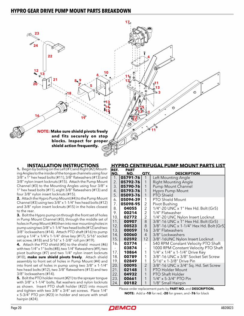
HyPRO CENTRIFuGAL PumP mOuNT PARTS LIST
1. 05791-76 1 Left Mounting Angle 2. 05792-76 1 Right Mounting Angle 3. 05790-76 1 Pump Mount Channel 4. 05793-76 1 Hypro Pump Mount 5. 05093-76 1 PTO Shield 6. 05094-39 1 PTO Shield Mount 7. 05098-95 2 Pivot Bushing 8. 04055 2 1/4”-20 UNC x 1” Hex Hd. Bolt (Gr5) 9. 00214 2 1/4” Flatwasher 10. 02772 2 1/4”-20 UNC Nylon Insert Locknut 11. 00907 8 3/8”-16 UNC x 1” Hex Hd. Bolt (Gr5) 12. 00523 8 3/8”-16 UNC x 1-1/4” Hex Hd. Bolt (Gr5) 13. 00059 16 3/8” Flatwashers 14. 00060 4 3/8” Lockwashers 15. 02592 12 3/8”-16UNC Nylon Insert Locknut 16. 03774 - 540 RPM Constant Velocity PTO Shaft - 03874 - 1000 RPM Constant Velocity PTO Shaft 17. 10864 1 1/4” x 1/4” x 1-1/4” Drive Key 18. 00789 1 3/8”-16 UNC x 3/8” Socket Set Screw 19. 02849 1 5/16” x 1-3/8” Drive Pin 20. 00095 2 3/8”-16 UNC x 3/4” Sq. Hd. Set Screw 21. 02148 1 PTO Holder Mount 22. 04932 1 PTO Shaft Holder 23. 00661 1 1/4” x 5-3/4” PTO Pin 24. 00182 1 1/8” Small Hairpin
REF. PART NO. NO. QTy. DESCRIPTION
1. Begin by bolting on the Left (#1) and Right (#2) Mount-ing Angles to the inside of the tongue channels using four 3/8” x 1” hex head bolts (#11), 3/8” flatwashers (#13) and 3/8” nylon insert locknuts (#15). Attach the Pump Mount Channel (#3) to the Mounting Angles using four 3/8” x 1” hex head bolts (#11), eight 3/8” flatwashers (#13) and four 3/8” nylon insert locknuts (#15).2. Attach the Hypro Pump Mount (#4) to the Pump Mount Channel (#3) using two 3/8” x 1-1/4” hex head bolts (#12) and 3/8” nylon insert locknuts (#15) in the holes closest to the rear.3. Bolt the Hypro pump on through the front set of holes in Pump Mount Channel (#3), through the middle set of holes in Pump Mount (#4) then into rear mounting holes in pump using two 3/8” x 1-1/4” hex head bolts (#12) and two 3/8” lockwashers (#14). Attach PTO shaft (#16) to pump using a 1/4” x 1/4”x 1-1/4” drive key (#17), 5/16” socket set screw, (#18) and 5/16” x 1-3/8” roll pin (#19).4. Attach the PTO shield (#5) to the shield mount (#6) with two 1/4” x 1” bolts (#8), two 1/4” flatwashers (#9), two pivot bushings (#7) and two 1/4” nylon insert locknuts (#10), make sure shield pivots freely. Attach shield assembly to front set of holes in Pump Mount (#4) and into front set of holes in pump using two 3/8” x 1-1/4” hex head bolts (#12), two 3/8” flatwashers (#13) and two 3/8” lockwashers (#14).5. Bolt the PTO holder mount (#21) to the sprayer tongue with 3/8” x 1-1/4” bolts, flat washers and nylon locknuts as shown. Insert PTO shaft holder (#22) into mount and tighten with two 3/8” x 3/4” set screws. Place 1/4” x 5-3/4” PTO pin (#23) in holder and secure with small hairpin (#24).
INSTALLATION INSTRuCTIONS
Please order replacement parts by PART NO. and DESCRIPTION.NOTE: Add a -10 for red, -20 for green, and -76 for black
Wednesday, January 19, 2005 10:18:33
NOTE: make sure shield pivots freely and fits securely on stop blocks. Inspect for proper shield action frequently.
12
3
4
6
8 97 5
101113
131412
11
1315
1315
11
16
17
18
19
20
1213
21
13
22
23
24
hypRO geAR dRive pUmp mOUnt pARts BReAkdOWn

AB20023 Page 21
1 07207-76 1 Pump Hanger 2 07206-76 1 Hypro Pump Mount 3 C9403 540S 1 Hypro Belt Drive Pump - PTOC600 10B150 1 Ace Belt Drive Pump 4 00523 6 3/8”-16 UNC x 1-1/4” Hex Hd. Bolt 5 00059 6 3/8” Flatwasher 6 02592 6 3/8”-16 UNC Nylon Insert Locknut 7 00914 2 3/8”-16 UNC x 1-1/2” Hex Hd. Bolt 8 01254 2 1/2”-13 UNC x 1-1/2” Hex Hd. Bolt 9 02178 2 1/2”-13 UNC Nylon Insert Locknut 10 05654 - 540 RPM Constant Velocity PTO Shaft 32” - 05674 - 1000 RPM Constant Velocity PTO Shaft 32” 11 02148-76 1 PTO Holder Mount 12 04932-76 1 PTO Holder Shaft 13 00095 2 3/8”x 16 UNC x 3/4” Sq. Hd. Set Screw 14 00182 1 1/8” Small Hairpin 15 00661-95 1 1/4” x 5-3/4” PTO Pin 16 05033 1 5/16”- 18 UNC x 1/4” Socket Set Screw 17 02849 1 5/16” x 1-3/8” Roll Pin
REF. PART NO. NO. QTy. DESCRIPTION
HyPRO/ACE BELT DRIvE PumP PARTS LIST
INSTALLATION INSTRuCTIONS1. Begin by bolting the pump hanger (#1) to the frame
with four 3/8” x 1-1/4” bolts (#3), two flatwashers (#4) and four nylon locknuts (#5) as shown.
2. Bolt pump (#2) to hanger using two 7/16” x 1-1/2” bolts (#6), flatwashers (#7) and nylon locknuts (#8).
NOTE: Be sure to match hydraulic motor driven pump capabilities to your tractors hydraulic system.
REF. PART NO. NO. QTy. DESCRIPTION 1 07207-76 1 Pump Hanger 2 FmC150HDy206 1 Ace Hydraulic Pump - C9303Hm1 1 Hypro Hydraulic Pump 3 00523 4 3/8”-16 UNC x 1-1/4” Hex Head Bolt 4 00059 2 3/8” Flatwasher 5 02592 4 3/8”-16 UNC Nylon Insert Locknut 6 04050 2 7/16”-14 UNC x 1-1/2” Hex Head Bolt 7 00205 2 7/16” Flatwasher 8 02771 2 7/16”-14 UNC Nylon Insert Locknut
REF. PART NO. NO. QTy. DESCRIPTION
HyPRO/ACE HyDRAuLIC PumP PARTS LIST
BELT DRIvE PumP mOuNTING1. Begin by bolting the pump hanger (#1) to the sprayer
tongue with 3/8” x 1-1/4” bolts(#4), flat washers (#5) and nylon insert locknuts (#6) as shown.
2. Bolt hypro pump mounting bracket (#2) to hanger using two 1/2” x 1-1/2” bolts (#8) and nylon insert locknuts (#9).
3. Next bolt pump (#3) to the bracket (#2) using two 3/8” x 1-1/2” bolts (#7), Flatwashers (#5) and nylon locknuts(#6)
If pump is used with manual panel, stabilizer brace
should be mounted to top hole on top left outside hole of pump hanger.
1
3
45
6
10
11
4
12
13
14
15
16
17
5
7
Please order replacement parts by PART NO. and DESCRIPTION.
Please order replacement parts by PART NO. and DESCRIPTION.
1
24
5
6
83
7
hypRO/ACe hydRAUliC pUmp mOUnt pARts BReAkdOWn

Page 22 AB20023
1
1
1
12
2
43
9
10
5
4
3
7 6
11
10
7 6
5
7
16
6
8
7
11
14
64
25
15
12
39
4013
7
(8)
2434
41
11
13
41
13
23
42
2221
1320
13
46
32
25
44
24
45
5224
4648
4747
46
4919
51
5052
57
25
55
54
5356
5656
29
17
17
16
25
25
24 15
38
60
6064
4528
48
43
1356
628 7 59
6013
41
8
7
63
28
24 15
27
2826
50
52
29
12
52
57
45
1136 10
14
55 GallonFlush Tank
Central Fill Kit
valve Body
8
8
56
13
18
31
33
35
31
33
35
To Boom
38
38
4848
6
7
7
77
36
8
8
4044
24
8
37
WITH OPTIONAL 55 GALLON FLuSH AND CENTRAL FILL
CentRiFUgAl pUmp & plUmBing

AB20023 Page 23
1. 5044 1 4 Agitation Jet 2. R1212 2 1/2” MPT Tee 3. P012D 2 1/2” Double Threaded Outlet 4. 5077v 2 Viton Grommet 5. N5P 2 Nut for Tank Outlets 6. BEL1034 2 1” MPT x 3/4” HB Elbow Fitting (GFP) 7. B12H 14 3/4” SS Gear Clamp 8. 340RB - 3/4” Rubber Hose 9. P200 PAv 2 2” Anti-Vortex Outlet Fitting 10. 5078v 3 Viton Grommet 11. N8P 4 Tank Outlet Nut 12. EL114 112 1 1-1/4” MPT x 1-1/2” HB Elbow Fitting (GFP) 13. B24H 8 1-1/4” SS Gear Clamp 14. P114A 2 1-1/4” Outlet Fitting 15. BEL114 1 3 1-1/4” MPT x 1” HB Elbow Fitting (GFP) 16. T34 2 3/4” HB Insert Tee 17. S2020 2 2” EPDM Wire Suction Hose 18. P55 23F 1 55 Gallon poly tank w/ 1 1/4 AV Fitting 19. uv200FP3 1 2” Single Union Poly Ball Valve 20. RvF100C 1 Line Strainer Cap 21. RvF140 1 Mesh Screen 22. RvF114G 1 Gasket for Line Strainer 23. RvF114B 1 Bowl for Line Strainer 24. B16H 8 1” SS Gear Clamp 25. 1010RB - 1” Rubber Hose 26. P100DA 2 1” Outlet Fitting 27. 03813 2 1” FPT Rinsing Spray Ball 28. 11067 4 1” MPT Nipple Fitting 29. uv200FP 1 2” Poly Ball Valve 31. 633B2020 1 Quick Coupler 2” MPT 32. FC1000 2 1” FPT x 1” FPT Coupling
REF. PART NO. NO. QTy. DESCRIPTION
REF. PART NO. NO. QTy. DESCRIPTION 33. 633F2020 1 Adapter 2” MPT F/ Quick Coupler 34. BTT100 1 1” FPT Tee (GFP) 35. 633B2020 1 Plug 2” F/ Quick Coupler 36. BRB114 1 1 1 1/4” MPT x 1” FPT Reducer BSHG 37. 9428090 1 Control panel 38. F1014 3 1 1/4” MPT Plug 40. BA1010 2 1” MPT x 1” HB, GFP 41. BA114 6 1 1/4” MPT x 1 1/4” HB 42. BA112 200 1 1 1/2” MPT x 2” HB (GFP) 43. BEL114 1 1 1/4” MPT x 1 1/4” HB Elbow (GFP) 44. BEL1010 1 1” HPT x 1” HB Elbow (GFP) 45. BTT114 2 1 1/4” FPT Poly Tee 46. B44H 4 2” SS Gear Clamp 47. EL200 2 2” MPT x 2” HB Elbow 48. BSE114 1 1 1/4” FPT x 1 1/4” MPT Elbow 49. A200 1 2” MPT x 2” HB (GFP) 50. BA200 112 1 2” MPT x 1 1/2” HB (GFP) 51. BRB200 114 1 2” MPT x 1 1/4” FPT Reducer 52. B32H 2 1 1/2” SS Gear Clamp 53. C9016 540 1 Gear Drive Pump 540 RPM 54. C9403 540S 1 Belt Drive Pump 600 RPM 55. C9303Hm1 1 Hypro Cent Pump 56. 1140RB 4 1 1/4” EPDM Hose 57. 1120RB 1 1 1/2” EPDM Hose 59. uv100FP3 1 Ball valve 1” single union 3-way poly w/ EPDM O RING 60. uv125FP3 3 Ball valve 1.25” single union 3-way poly w/ EPDW O-RING 62. BEL1034 1 1” MPT x 3/4” HB Elbow 63. EL114 34 1 1 1/4” MPT x 3/4” HB Fitting 64. Bm1140 3 1 1/4” MPT Nipple Fitting
Please order replacement parts by PART NO. and DESCRIPTION.
plUmBing pARts list

Page 24 AB20023
1. Run approximately 50 gallons of water in the tank.
2. Open the poly ball valve in the pump intake line.
3. Close the wedge valve on the front of the control panel.
4. Close the wedge agitation valve on the control panel back.
5. Make sure the ratchet valve on the control panel back is in the open position.
6. Open the three manual valves on the control panel.
7. Start the pump and run at 540 RPM.
8. Open the large wedge valve on the front of control panel until the gauge reads approx. 3 PSI over your desired spraying pressure with all three booms spraying.
9. Open the wedge agitation valve on the control panel until the gauge drops to your desired spraying pressure.
Example: If desired spraying pressure is 30 PSI open the wedge valve on the back of the control panel until the gauge reads 33 PSI. After this, open the wedge agitation valve on the control panel until the gauge drops back down to 30 PSI. (This is to ensure the recommended pressure to the tank jet agitators).
10. Check for leaks.
11. Make certain all bolts and clamps are tight.
1. Run approximately 50 gallons of water in the tank.
2. Open the poly ball valve in the pump intake line. Important: Remove top plug on pump to bleed all air from the suction line to the pump or damage will result to the seals. (Pump cannot be run dry).
3. Close the wedge valve on the front of the control panel.
4. See “Panel Mounting and Operation” in Electric Control Panel Instruction Manual.
stARt-Up instRUCtiOns FOR CentRiFUgAl pUmps With mAnUAl COntROl pAnel
stARt-Up instRUCtiOns FOR CentRiFUgAl pUmps With eleCtRiC COntROl pAnel

AB20023 Page 25
1
4
5
15
6
8
10
9
11
12
12
13
13
11
3
10
7
11
5
15
11
14
2
16
17
Existing handrail bracket
DFS 55 mOuNTING ON HP (500/600 GL.) SPRAyER
1.Remove and discard existing 1/2” x 1-1/4” bolts which mount the existing handrail brackets. Remount hand-rail brackets along with rear mounting arms (#6,7) to the sprayer frame using four 1/2” x 1-1/2” bolts (#14), and four 1/2” locknuts (#5) as shown.
2.Now mount the front mounting arms (#8,9) to the sprayer frame using four 3/8” x 1-1/4” bolts (#12), and
four 3/8” locknuts (#13) as shown.3.Attach the crossmember mounts (#10) to the front and rear mounting arms using four 3/8” x 2” sq. U-
bolts (#11), and eight 3/8” locknuts (#13).4.Mount the tank saddles (#2) on the crossmember
mounts (#10) with four 1/2” x 1-1/4” bolts (#4) four 1/2” flatwashers (#15), and four 1/2” locknuts (#5).
5.Lay tank (#1) in the tank saddle (#2). Secure tank with the tie down straps (#3) four 5/16” x 4” bolts (#16), and four 5/16” locknuts (#17) as shown.
ASSEmBLy INSTRuCTIONS14
PARTS LIST FOR mOuNTING ON HP SPRAyER
REF. PART NO. NO. QTy. DESCRIPTION
1. P55 23F 1 Tank (55 gallon) w/ 1-1/4” AV Fitting - PL5R 1 Tank Lid 2. 02645-76 2 Tank Saddle 3. 04353 2 Tie Down Strap - 05785-95 4 Strap Anchor - 02729-95 2 Strap Buckle 4. 00967 4 1/2”-13 UNC x 1-1/4” Hex Head Bolt Gr.5 5. 02178 8 1/2”-13 UNC Nylon Insert Locknut 6. 07140-76 1 HP Right Rear Mounting Arm 7. 07141-76 1 HP Left Rear Mounting Arm 8. 07144-76 1 HP Right Front Mounting Arm 9. 07145-76 1 HP Left Front Mounting Arm 10. 07148-76 2 Crossmember Mount 11. 05294 4 3/8”-16 UNC Sq. U-bolt (fits 1” x 2” tube) 12. 00523 4 3/8”-16 UNC x 1-1/4” Hex Head Bolt 13. 02592 12 3/8”-16 UNC Nylon Insert Locknut 14. 01254 4 1/2”-13 UNC x 1-1/2” Hex Head Bolt Gr.5 15. 00085 4 1/2” Flatwasher 16. 04352 4 5/16”-18 UNC x 4” F.T Hex Hd. Bolt 17. 02802 4 5/16”-18 UNC Nylon Insert Locknut
Please order replacement parts by PART NO. and DESCRIPTION.
dFs 55 mOUnting

Page 26 AB20023
REF. PARTNO. NO. QTy. DESCRIPTION
1. P55 23F 1 Tank (55 Gallon) 3. 1140RB - 1-1/4” Rubber Hose 4. BA114 2 1-1/4” MPT x 1-1/4” HB-GFP 5. 340RB - 3/4” Rubber Hose 6. BRB200 114 1 2”x1-1/4” Reducer Bushing-GFP 7. EL114 34 1 1-1/4” MPT x 3/4” HB Elbow-GFP 8. T34 1 3/4” Tee HB x HB x HB 9. 03813 2 Spinner 10. P100DA 2 1” Tank Fitting 11. 11067 2 1” MPT Nipple-GFP 12. B24H 2 Hose Clamp Fits 1-1/4” Hose 13. B12H 6 Hose Clamp Fits 3/4” Hose 14. BEL1034 2 1” MPT x 3/4” HB Elbow-GFP Please order replacement parts by PART NO. and DESCRIPTION.
Note: DFS 55 kit includes only parts called out in breakdown and parts list. Other parts are included in separate packages.
DFS 55 (PLumBING) PARTS LIST
10
8
1313
13
3
5
5
12
12
1212
4
1
6
9
137
4
dFs 55 plUmBing BReAkdOWn & pARts list

AB20023 Page 27
FOAm mARKER (DFm60), ELECTRIC CONTROL PANEL, AND HAND GuN STORAGE BRACKET
mOuNTING LOCATIONS
mOuNTING INSTRuCTIONS1. Mount the DFM60 mounting brackets (#1 & #2), using
four 1/2” x 1-1/4” bolts (#3), flatwashers (#4) and nylon locknuts (#5), provided with DFM60.
2. Mount the control panel using four 3/8” x 1” bolts (#6), lockwashers (#7) and nuts (#8) provided with panel.
3. Mount handgun storage bracket (#9) using existing bolts already in tongue.
2
3
9
6
8
1
45
DFmFoam marker
Control Panel
DBHGHandgun
Storage Bracket
7
QuICK REFILL OPERATING INSTRuCTIONS (CPTK2)Start by having all valves in closed position.
1. Remove the cap (No. 10) from the NPT quick coupler adapter (No. 9) and attach the 2” hose shank coupler (No. 11) which is connected to the nurse tank hose.
2. Open valve (No. 8) and the valve on the nurse tank. Make sure there is liquid up to the pump before starting the pump. Running the pump dry will cause seals to fail.
3. When the tank is full, close valve (No. 8) . Open the agitation line valve on the control panel. The unit is now agitating.
4. Close nurse tank valve, disconnect coupler (No. 11) and re-place cap (No. 10)
NOTE: Apply thread sealant to the fittings. Do not use sealant on external threads of tank outlet fitting.
REF. NO. PART NO. QTy. DESCRIPTION
QuICK REFILL (CPTK1) PARTS LIST
Please order replacement parts by PART NO. and DESCRIPTION.
1. Bm1140 2 1-1/4”MPT Nipple (GFP) 2. BTT114 2 1-1/4” FPT Tee (GFP) 3. A114 112 1 1-1/4” MPT x 1-1/2” HB (GFP) 4. B32H 2 1-1/2” SS Gear Hose Clamp 5. 1120RB - 1-1/2” Rubber Hose 7. BA200 112 1 2” MPT x 1-1/2” Hose Barb (GFP) 8. uv200FP 1 2” Poly Ball Valve 9. 633F2020 1 2” Adapter - Male NPT 10. 634B2020 1 2” Cap for Adapter 11. 633C2020 1 2” Hose Shank Coupler 12. 02757 1 7/16” NC x 3” U-Bolt 13. 01811 1 Quick Refill Mounting Bracket 14. 00967 2 1/2”-13 UNC x 1-1/4” Hex Head Bolt (Gr 5) 15. 02178 2 1/2”-13 UNC Nylon Insert Locknut 16. 00205 2 7/16” Flatwasher 17. 02771 2 7/16”-14 UNC Nylon Insert Locknut
12
3 4
5
4
7
89
101112
16
1713
14
15
To Control
6
(OptiOnAl Cptk1) qUiCk ReFill pARts BReAkdOWn & instAllAtiOn

SPRAyER CHECKLIST:Downtime caused by field breakdowns is costly and time consuming. many breakdowns can be eliminated by periodic equipment maintenance. By spending time reviewing this checklist before seasonal spraying application time and following proper after-season care, you can save time and money later.
NOTE: DETHmERS mANuFACTuRING COmPANy does not and will not make any recommendations concern-ing application of various chemicals or solutions. These recommendations relate to either amount or procedure of materials applied. If you have any questions regarding application of certain chemi-cals or solutions, contact your chemical supplier and follow chemical manufacturer recommen-dations.
Check Before Going To The Field :
1. NOZZLES Check tip for excessive wear by checking for grooves
in or near tip opening. Check nozzle spacing by start-ing at center and working outwards. Check boom for proper height.
2. HOSES Check all hoses for worn or soft spots. Be sure all hose
clamps are tightened and hoses are not kinked or pinched. Check for leakage in any lines.
3. TANK Remove and clean agitator orifices. Check orifices
for excessive wear by checking for grooves in or near orifice opening. Inspect fitting and grommets to insure they are in good condition.
4. CONTROLS Check for leakage, plugging, or wear on all valves, fit-
tings, etc. Clean off any build up of foreign material.
5. PumP Check to be sure pump turns freely.
6. FRAmE Be sure all bolts are tightened.
7. REPLACEmENT PARTS Replace all worn or damaged parts.
• Keephands,feet,andlooseclothingawayfromrotatingparts.
• Wearprotectiveclothingrecommendedbyyourchemicaland fertilizer manufacturer when working with chemicals.
WARNING: To Prevent Serious Injury Or Death
After Season Care:
NOTE: It is important to wear proper safety equipment when cleaning the sprayer. See your chemical or fertil-izer package for this information.
1. After spraying chemicals, run water mixed with cleaners through tank, pump and all hose hookups. If wettable powder dries out in the system, it is very difficult to put back into suspension and can cause malfunction, damage or injury.
2. When cleaned, tank should have all openings closed or covered to keep dirt from entering.
3. Pump should be flushed with soluble oil and pump ports plugged to keep out moisture and air.
4. Disassemble tips and rinse with water or cleaning solution. (Appropriate for chemical sprayed).
5. Clean tip opening with a wooden toothpick. Never use wire or hard object that could distort opening.
6. Dispose of all unused chemicals or solutions in a proper and ecologically sound manner.
6. Water rinse and dry tips before storing.


![2018 SPRAYER CATALOG - Demco Products · 2018 SPRAYER CATALOG Doing Our Best to Provide You the Best ___ LMUKW XZWL]K\[ KWU ... • 12' and 18' booms feature floodjet tips and spring](https://img.dokumen.tips/doc/110x75/5ca0964b88c99321188d7441/2018-sprayer-catalog-demco-products-2018-sprayer-catalog-doing-our-best-to.jpg)