Embed Size (px)
Citation preview

SINE WAVE INVERTER SINUS-WECHSELRICHTER ONDULEUR SINUSOÏDAL
AJ SERIES
User’s and installer’s manual
Betriebs-und Montageanleitung
Manuel d’utilisation et de montage Mis en forme : Français(Suisse)

STUDER Innotec AJ
AJ V2.3 2/30
English description................................................................................................... 3 Introduction ................................................................................................................... 3 Warning .......................................................................................................................... 3 Installation ..................................................................................................................... 3 Connection..................................................................................................................... 4 Use.................................................................................................................................. 5 Model with stand-by system......................................................................................... 6 Safety.............................................................................................................................. 7 Maintenance................................................................................................................... 8 Warranty limit ................................................................................................................ 8 Limits of manufacturer liability .................................................................................... 8 JT8 Remote control for AJ 1000-2400.......................................................................... 9 Technical data ............................................................................................................. 10 Model with built-in solar charger (option – S)........................................................... 11
Deutsche Beschreibung ......................................................................................... 12 Einführung ................................................................................................................... 12 Vorsicht ........................................................................................................................ 12 Installation ................................................................................................................... 12 Anschluss .................................................................................................................... 13 Anwendungen.............................................................................................................. 14 Lasterkennungsschaltung „stand-by“ ...................................................................... 15 Sicherheiten ................................................................................................................. 16 Unterhalt....................................................................................................................... 17 Garantieausschluss .................................................................................................... 17 Haftungsausschluss ................................................................................................... 17 JT8 Fernsteuerung für AJ 1000-2400......................................................................... 18 Technische Daten........................................................................................................ 19 Solarladeregler für fotovoltaïsche Solarmodule (Option – S) ................................. 20
Instructions en français.......................................................................................... 21 Introduction ................................................................................................................. 21 Mise en garde .............................................................................................................. 21 Installation ................................................................................................................... 21 Raccordement ............................................................................................................. 22 Utilisation ..................................................................................................................... 23 Modèles avec stand-by ............................................................................................... 24 Sécurités ...................................................................................................................... 25 Maintenance................................................................................................................. 26 Exclusion de la garantie ............................................................................................. 26 Exclusion de la responsabilité ................................................................................... 26 J T8 Commande à distance pour AJ 1000-2400........................................................ 27 Données techniques ................................................................................................... 28 Modèles avec chargeur solaire (option – S).............................................................. 29

STUDER Innotec AJ
AJ V2.3 3/30
English description
Introduction The sine wave inverters of the AJ series have been designed to meet industrial and domestic needs. They meet the highest requirements of comfort, safety and reliability. Any device designed for the public electrical network of 230 V 50 Hz can be connected to them (up to the nominal power of the inverter). The AJ series is the perfect source of voltage in any place where the public network is not available. This document is an essential part of the inverter and must always be carried with it and be at the disposition of anyone working on the installation. Should you have any doubt or question, do not hesitate to contact your specialist salesperson who will give you the best advice.
Warning A deficient assembly could result in damage to the device, cause function failures or potential damage to the users. The working device generates a high voltage which might be lethal in case of contact. So, any manipulation of the inverter must be carried out with utmost care.
THE OWNER MUST NOT MANIPULATE ANY PIECE INSIDE THE INVERTER. Opening the inverter or using it incorrectly will result in the immediate loss of the warranty. No current or tension generating device (public grid, generator,...) may be con-
nected to the outlet of the inverter because this could result in its destruction.
The inverter AJ is to be used only with a lead battery. As for the use of batteries, follow the manufacturer’s instructions.
Installation The AJ sine wave inverter is an electronic device, for which some caution must be taken when installing it: Place where the inverter is to be installed: Out of reach of unauthorised persons, specially children. In a dry place (max. 95% humidity), and in any case with no condensation. Not directly on top of the batteries. Ventilation must be free, and a space of 10 cm. on each side is needed for good evacuation of the internal heat. No easily inflammable material should be placed directly underneath or close to the AJ Fitting the inverter The inverter is fitted on a non flammable surface by screws (max. 4mm for AJ 275-AJ 1300 or max. 8mm for AJ 2100 and 2400) using the four holes provided. The fitting screws are not supplied with the inverter. It may be fit into any position.

STUDER Innotec AJ
AJ V2.3 4/30
Connection The connection of the inverter should be done with utmost care. First connect the consumer devices so as to prevent any further contact once the 230 V voltage is present. The technical data and connection’s description is either under one side of the inverter or onto the cable connection side. Installation is to be made only by authorised persons. Connecting the consumer devices The AJ inverter is supplied with a 230 V cable for the consumer devices. This connection must be done observing the colours: Yellow-green: earth Brown: phase Blue: neutral Once the consumer devices are connected, make sure that they are turned off before connecting the battery
Note An Inverter constitutes an independent power supply from the grid and could be considered in the same way as a generator set. The phase and the neutral are not differentiated. The voltage in between the phase and the neutral is 230V. An appropriate divisor establishes a 115V voltage in between neutral and earth, and the phase and earth. According to the local prescriptions or particular requirement, (example: use of a ground fault detector) a true neutral may be established by connecting the neutral and the earth wire together. The so connected point, may be connected with an existing earth: earth of building; the chassis of vehicle or the hull of ship. Equivalent schema
Connecting the battery Once the consumer devices are connected, make sure that the installations instructions of the 230V has been followed with utmost care before connecting the battery.

STUDER Innotec AJ
AJ V2.3 5/30
The cable of the battery is supplied with the inverter and already connected in it. A fuse must be installed on the battery. Connect the battery observing carefully the polarity. The AJ inverter, except AJ 2100-12, is protected against inversion by a fuse, but if the polarity should be inverted, the inverter must be sent to the manufacturer for control. Connect the battery using the following colours: BLACK cable: negative pole (-) RED cable: positive pole (+) For AJ 275-400, dominant colour is applicable When connecting the battery, there is a spark (Danger of explosion!), because of the charging of the internal filtering capacitors. Check that the cables are well adjusted and well tightened. As long as it is possible, do not extend the cables supplied with the batteries. Extending them may increase the losses and cause malfunction of the inverter. Once the inverter is connected to the batteries, a 230 V voltage is present in the outlet of the inverter.
Use Control and indicators Control switch on/off There is a switch on the inverter to activate or deactivate it. Use this function to save the
energy of the batteries when you are not using the inverter. Green indicator A green light on the inverter indicates its function mode: Illuminated: a 230 V voltage is present
in the outlet, the inverter is on. Blinking:
_ _ _ : No load (stand-by) __ __ __ : the 230 V voltage has been cut due to an alarm; the inverter will resume function when the failure has disappeared (see the failure table).
Off: the 230 V voltage is NOT present in the outlet, the inverter is off.
Acoustic indicator The AJ inverter has an acoustic indicator for the following instances: Intermittent beep: there is a failure in the inverter and the outlet voltage will be interrupted. Possible failures: Overheat: the acoustic indicator beeps
3 ºC before cutting the tension. If the temperature reaches its normal level, the voltage in the outlet is not interrupted.
Low battery voltage: the indicator beeps for a minute before the interruption. If the voltage of the battery rises, the outlet voltage is not interrupted.
STUDER Innotec AJ
AJ V2.3 6/30
Continuous beep for two seconds: you have pressed the ON/OFF switch to restart the inverter. The tension in the outlet will be immediately present after the acoustic signal.
Model with stand-by system The inverters from the AJ 500-12 are equipped with a stand-by system which is in function when no load is connected. In that situation the inverter is in low power consumption mode. The output tension is not continuously present and the LED is blinking as long as no load is detected. The minimal load detected can be adjusted between 1 and 20 W. In most cases this adjustment is not necessary. This adjustment is made with a small screw driver in the hole marked stand-by. This adjustment is made with a small screw
driver in the hole marked stand-by. Adjusting the switching-on level is as follows: Switch off all consuming devices; turn the Turning Knob to the Left (counter-clockwise)until the LED is blinking, switch ON the smallest consuming device (i.e. Mobile phone charger); turn the Turning Knob slowly to the right until LED is lit continuously. Check that the inverter will go back in stand-by mode when you remove the load. If not, this means that the load is too small to be detected. If the stand-by is not required, turn the Knob fully to the right. In the full counter clockwise position, the sensibility is minimal (20 W). Do not push on the screw driver. NOTE: in this mode the output voltage is intermittently present at the output

STUDER Innotec AJ
AJ V2.3 7/30
Safety The inverter is electronically protected. But protection against polarity inversions of the battery occurs with an internal fuse, except for AJ 2100-12 inverter, which has no fuse. The following table will show you the different failures and their consequences.
FAILURE CONSEQUENCE SOLUTION Low battery voltage Voltage < 1.8V/cell
Inverter momentarily stopped, the green indicator blinks.
Automatic restart when the battery voltage rises
Deep discharged battery (voltage <1,5V/cell)
Inverter stopped Inverter should be manually restarted when the battery as reach 2V/cell
Overheating Inverter momentarily stopped, the green indicator blinks.
Automatic restart when the temperature reaches the normal range.
Battery over voltage Inverter stopped. Wait until the battery voltage reaches the correct level. Push the ON/OFF switch to reactivate the inverter
Short circuit in the outlet Inverter stopped. Eliminate the short circuit. Push the ON/OFF switch to reactivate the inverter.
Overload Inverter stopped. Use the inverter only in the range of its nominal power. Regular use in overload power diminished the lifetime of the inverter. Push the ON/OFF switch to reactivate the inverter.
Inversion of the battery polarity
Internal fuse broken down Back to manufacturer for testing

STUDER Innotec AJ
AJ V2.3 8/30
Maintenance The inverters of the AJ series do not need any special maintenance. The casing may be cleaned with a damp cloth (not wet). In the case of malfunction, the inverter should be sent back to the manufacturer for control in its original packing. Before sending the inverter, check the table above. The battery is loaded and is in accordance to the inlet nominal tension of the device. The consumer devices do not have any defects or overload for the inverter. Should you contact your salesperson, note the following points before calling: (you will find this information on the label underneath the inverter) - Series number - Power of the inverter - Inlet nominal voltage of the inverter Before sending back the inverter, do take care that it is well packed. The inverter must be in a stiff carton box and be well protected on all sides by mean of an anti-shock and isolating layer of min. 5cm thickness. The damages occurring during the transport are not covered by the warranty.
Warranty limit The warranty period is 2 years. It will be considered void if the unit has suffered any physical damage or alteration, either internally or externally, and does not cover damage arising from improper use like: − Reverse of battery polarity − Inadequate input voltage (over voltage) − Back-feed of the inverter output by public
network, generator or any other source.
− Mechanical shock or deformation especially by transport due to an inadequate package.
− Contact with liquid or oxidation by condensation
− Use in inappropriate environment (dust, corrosive vapour, humidity, high temperature,...)
This warranty will not apply where the product has been misused, neglected, improperly installed, or repaired by anyone other than STUDER INNOTEC or a company authorised by STUDER INNOTEC. In order to qualify for the warranty, the product must not be disassembled or modified.
Limits of manufacturer liability STUDER INNOTEC cannot control the installation, use and maintenance of the inverter. Thus, we are not responsible for damages, costs or losses resulting from an installation which is not in accordance with the regulations or inappropriate use or maintenance. The customer is always responsible for the use of the inverters STUDER INNOTEC. This device has not been designed and is not warranted for use in life support apparatus or any other critical device with potential risks of important harm to people or to the environment. We do not accept any responsibility for any violation of patent rights or other third person rights resulting from the use of the inverter. STUDER INNOTEC keeps the right to modify their products without previous notice.

STUDER Innotec AJ
AJ V2.3 9/30
JT8 Remote control for AJ 1000-2400 Functions on remote control are the same as control and indicator on the inverter (see chapter Use) Remote control should be connected with the inverter with the original 10m. STUDER cable or any RJ11/6p 1:1 cable up to max 50m.
STUDER Innotec AJ
AJ V2.3 10/30
Technical data
MODEL AJ 275 AJ 350 AJ 400 AJ 500 AJ 600 AJ 700 Battery voltage (V) 12 24 48 12 24 48 Input voltage (V) 10.5 - 16 21 - 32 42 - 64 10.5 -
16 21 - 32 42 - 64
Continuous / 30’ power (VA) 200/275 300/350 300/400 400/500 500/600
500/700
Stand-by / ON @ no load (W) 0.3*/1.9 0.3*/3.3 0.4*/5 0.3/3.8 0.4/8.5 1/10 Maximum efficiency (%) 93 94 94 93 94 94 Dim. 142 x 84 x L (mm) L= 163 252 eight (kg) 2.4 2.6 2.6 4.5 Remote control plug (RCM-01) Option Option Load detect. (Stand-by) 1-20 W
with option S V
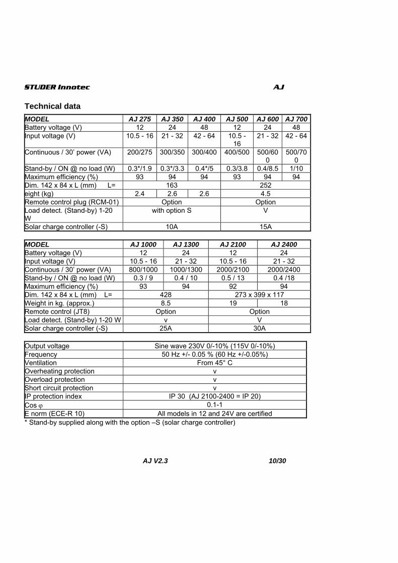
Solar charge controller (-S) 10A 15A MODEL AJ 1000 AJ 1300 AJ 2100 AJ 2400 Battery voltage (V) 12 24 12 24 Input voltage (V) 10.5 - 16 21 - 32 10.5 - 16 21 - 32 Continuous / 30’ power (VA) 800/1000 1000/1300 2000/2100 2000/2400 Stand-by / ON @ no load (W) 0.3 / 9 0.4 / 10 0.5 / 13 0.4 /18 Maximum efficiency (%) 93 94 92 94 Dim. 142 x 84 x L (mm) L= 428 273 x 399 x 117 Weight in kg. (approx.) 8.5 19 18 Remote control (JT8) Option Option Load detect. (Stand-by) 1-20 W v V Solar charge controller (-S) 25A 30A Output voltage Sine wave 230V 0/-10% (115V 0/-10%) Frequency 50 Hz +/- 0.05 % (60 Hz +/-0.05%) Ventilation From 45° C Overheating protection v Overload protection v Short circuit protection v IP protection index IP 30 (AJ 2100-2400 = IP 20) Cos ϕ 0.1-1 E norm (ECE-R 10) All models in 12 and 24V are certified * Stand-by supplied along with the option –S (solar charge controller)

STUDER Innotec AJ
AJ V2.3 11/30
Model with built-in solar charger (option – S) The AJ inverters of the AJXXXX-S series have a built-in solar charger. The built-in solar charge controller is of the shunt and floating type. It may only be used by solar generators. The maximal voltage of the solar modules is 23 V for 12 V applications, 46 V for 24 V applications and 90V for 48V applications. To fix it, first install the cables of the inverter observing the following instructions BEFORE connecting the solar cells. Then install the cables of the solar generator observing the polarities (red for the + and black for the -).
Function The orange indicator on the inverter shows the mode of function: Illuminated: the solar charge is to its
maximum. Not illuminated: the solar generator is
not connected or the battery is completely loaded.
Blinking: The battery is more than 95% loaded and the charger is in the floating mode to complete the load (the blinking frequency varies depending on the capacity of the battery and the power of the solar generator).
Wiring for AJ 2100/2400-S inverter On AJ 2100/2400-S inverter, a preinstalled cable (2 x 6mm2) replaces the terminals. Wiring should be done through a connecting box. Connection : Positive (+) pole to the brown or red cable. Negative (-) pole to the blue or black cable.
STUDER Innotec AJ
AJ V2.3 12/30
Deutsche Beschreibung
Einführung Die Wechselrichter der Serie AJ sind für den Betrieb von allen handelsüblichen 230V Geräten konzipiert worden. Die AJ genügen den höchsten Anforderungen an Zuverlässigkeit, Sicherheit und Komfort. Jedes für das 230V-Wechselstromnetz geeignete Gerät kann auch mit einem AJ betrieben werden. Ein AJ ist die ideale Spannungsquelle überall da wo das öffentliche Netz nicht hinführt. Diese Beschreibung ist in jedem Fall Teil der Lieferung eines AJ. Sie muss allen Personen welche mit einem AJ arbeiten zur Verfügung stehen ! Bei eventuellen Fragen oder Unklarheiten kann Ihnen der Händler Auskunft geben
Vorsicht Eine falsche Behandlung oder Montage des Wechselrichters kann schwerwiegende Folgen haben ! Der AJ erzeugt eine 230V-Sinusspannung wie im öffentlichen Stromnetz. Jegliche Berührung kann fatale Folgen haben ! Die Installationsarbeiten mit dem Wechselrichter AJ verlangen besondere Aufmerksamkeit und dürfen nur von geschultem Personal ausgeführt werden und müssen in jedem Fall den jeweils gültigen Installationsvorschriften entsprechen.
Der AJ darf in keinem Fall geöffnet wer-den. Das Öffnen oder die nicht konforme An-wendung des AJ bedeuten den Verlust jeglicher Garantieansprüche.
Der AJ darf mit keiner anderen Span-nungs- oder Stromquelle als mit Blei-batterien betrieben werden. Am Ausgang des AJ dürfen keine Span-nungs- oder Stromquellen wie Not-stromgeneratoren, das öffentliche Netz usw. angeschlossen werden, da der Wechselrichter zerstört werden könnte. Der Einsatz von Batterien verlangt besondere Vorsicht. Befolgen Sie darum unbedingt die Richtlinien des Batterieherstellers.
Installation Der Sinuswechselrichter AJ ist ein elekt-ronisches Gerät. Für dessen Installation sind darum einige Vorsichtsmassnah-men zu beachten. Der Montageort sollte gegen unbefugten Zugriff gesichert sein (vor allem auch vor Zugriff von kleinen Kindern). In einem trockenen Raum mit einer Luftfeuchtigkeit von max. 95% ohne Kondensation. Nicht direkt über der Batterie. Bei den Lüftungsein- bzw. Auslässen muss für eine unbehinderte Lüftung 10cm Freiraum belassen werden. In der Umgebung des Wechselrichters darf sich kein leicht brennbares Material befinden oder darunter gelagert werden. Befestigung des AJ Der Wechselrichter kann, auf einer nicht brennbaren Unterlage, mit Hilfe von 4 Schrauben (Durchm. max. 4mm für AJ 275-AJ 1300 oder Durchm. max. 8mm für AJ 2100 und 2400) in jeder beliebi-gen Lage montiert werden. Für die Be-

STUDER Innotec AJ
AJ V2.3 13/30
festigung dürfen nur die 4 von aussen zugänglichen Löcher verwendet werden. Die Befestigungs-Schrauben sind nicht beigelegt.
Anschluss Der Anschluss des AJ muss mit beson-derer Vorsicht ausgeführt werden. Eine sichere und einwandfreie Funktion der Anlage wird dadurch gewährleistet. Die Gerätedaten und die Anschlussbezeich-nung befinden sich auf der Gehäuse-unterseite oder auf der Kabelanschlus-seite. Vor dem Anschluss des AJ an die Batterie muss das Kabel OUT 230V mit einer Steckerkupplung(weiblich) versehen werden oder bei einer festen Installation muss der Anschluss entsprechend den Installationsvorschriften von geschultem Personal ausgeführt werden. Anschluss der Verbraucher Der Wechselrichter AJ wird mit bereits angeschlossen Kabeln geliefert. Das
schwarze 3-adrige Kabel für den 230V-Ausgang muss entsprechend den fol-genden Farben angeschlossen werden. Gelb-/Grün : Erdleiter Braun : Phase Blau : Neutral Vor dem Anschluss der Batterie muss darauf geachtet werden, dass die ange-schlossenen Verbraucher ausgeschaltet sind. Bemerkung : Ein Wechselrichter ist eine vom Netz unabhängige Span-nungsquelle Vergleichbar mit einem Notstromgenerator. Phase und Neutral-leiter können darum vertauscht werden. Zwischen Phase und Neutralleiter liegt die Spannung von 230V. Zwischen Phase und Erde sowie zwischen Neutral und Erde liegen jeweils 115V an. Je nach Installationsvorschriften können Neutral-Leiter und Erde verbunden wer-den. Prinzipschema
Anschluss der Batterie Vor dem Anschluss der Batterie muss sichergestellt sein, dass die 230V In-stallation vorschriftsgemäss ausgeführt wurde.

STUDER Innotec AJ
AJ V2.3 14/30
Der AJ wird mit angeschlossen Batterie-kabeln geliefert. Beim Anschliessen der Batterie muss unbedingt auf die richtige Polarität geachtet werden. Die AJ, mit Ausnahme des AJ 2100-12, sind wohl durch eine Sicherung gegen Verpolung geschützt. Für einen eventuellen Sicherungswechsel muss der AJ zur Kontrolle an den zuständigen Händler gebracht werden. Draht Schwarz: -Minus-Pol Draht Rot : + Plus-Pol Für die Kabel den AJ 275-350-400 gelten die jeweils dominierenden Farben! Den AJ an die Batterie anschliessen. Beim Anschliessen der Batterie entsteht ein Funken (EXPLOSIONSGEFAHR!) wegen der Ladung der internen Kondensatoren. Die Batterie muss mit einer Sicherung auf der Batterieklemme versehen sein ! Kontrollieren Sie, dass die Anschlüsse gut festgeschraubt sind. Die Batteriekabel sollten nicht verlängert werden. Eine Verlängerung der Batte-riekabel bedeutet grössere Verluste und oder Funktionsstörungen des AJ und somit auch der angeschlossenen Geräte. Sobald der AJ an der Batterie ange-schlossen wird, ist er eingeschaltet und es liegen 230V am Ausgang.
Anwendungen Bedienung und Anzeigen Steuertaste on/off Mit der Drucktaste kann der AJ ein- und ausgeschaltet werden. Schalten Sie den Wechselrichter mit dieser Taste aus, wenn Sie keine Energie brauchen. Grüne Leuchte Eine grüne Leuchtdiode (LED) zeigt den Funktionszustand des Wechselrichters an. LED leuchtet : Der Wechselrichter ist in
Funktion - am Ausgang liegen 230V. LED blinkt :
_ _ _ : Der Wechselrichter ist im Stand-by-Betrieb. __ __ __ : Der Wechselrichter ist we-gen eines Alarms vorübergehend aus-geschaltet. Nach verschwinden des Alarms schaltet sich der Wechselrich-ter automatisch wieder ein. (Die mögli-chen Alarmgründe sind auf der folgen-den Tabelle aufgeführt.)
LED gelöscht : Der Wechselrichter ist ausgeschaltet, am Ausgang liegt keine 230V-Spannung.
Akustischer Signalgeber Der Wechselrichter AJ ist mit einem akustischen Signalgeber ausgerüstet welcher in folgenden Fällen piept : Intermittierender Ton : Signal, dass der Wechselrichter sich im Alarmzustand

STUDER Innotec AJ
AJ V2.3 15/30
befindet und demnächst die Ausgangs-spannung abschalten wird. Mögliche Fehler : Überhitzung : Alarm 3°C bevor der
Wechselrichter abschaltet. Einen Teil der Last abschalten, damit der Wech-selrichter nicht mehr überlastet ist und sich abkühlen kann.
Unterspannung der Batterie : Wenn die Batteriespannung zu tief fällt, pfeift der Signalgeber eine Minute lang bevor der Wechselrichter abschaltet.
Dauerton während 2 Sek. : Warnsignal, dass 2 Sekunden nach dem Einschalten mit der Taste ON/OFF der Wechselrichter einschaltet, und dass an dessen Ausgang 230V anliegen !
Lasterkennungsschaltung „stand-by“ Alle Wechselrichter ab AJ 500-12 sind mit einem Stand-by-System ausgerüstet. Um die Batterie nicht unnötig zu entladen, schaltet sich der Wechselrichter automatisch aus, wenn kein Verbraucher angeschlossen ist, und automatisch wieder
ein, wenn ein Verbraucher eingeschaltet wird. Die LED blinkt, wenn der Wechselrichter im Stand-by- Modus ist. Der Einschaltpegel kann mit dem Drehknopf „STAND-BY“ mit einem kleinen Schraubenzieher eingestellt werden. Das Einstellen des Ein-schaltpegels geschieht folgendermas-sen: Sämtliche Verbraucher ausschal-ten; Den Drehknopf nach links (Gegen-uhrzeiger) drehen bis die LED blinkt; den kleinsten Verbraucher einschalten (z.B. Ladegerät für das Mobiltelefon); Drehknopf langsam nach rechts drehen bis die LED leuchtet. Danach zur Kon-trolle diesen kleinen Verbraucher aus-schalten,-der Wechselrichter muss nach einigen Sekunden wieder im Stand-by-Modus arbeiten. Geschieht dies nicht, ist die Last des Verbrauchers zu klein um erkannt zu werden. Ist der Stand-by- Modus nicht er-wünscht, muss der Drehknopf ganz nach rechts gedreht werden. VORSICHT: Auch im Standy-Modus liegen am Ausgang zeitweise 230V an!

STUDER Innotec AJ
AJ V2.3 16/30
Sicherheiten Die Wechselrichter AJ sind mit diversen elektronischen Systemen geschützt. Als Schutz gegen Verpolung dient eine Schmelzsicherung. Der AJ 2100-12 enthält keine Schmelzsicherung und ist somit nicht gegen Verpolung geschützt!
FEHLER WIRKUNG LÖSUNG Batteriespannung zu tief
Wechselrichter ist vorü-bergehend gestoppt. Die grüne LED blinkt
Nach Wiederanstieg der Batteriespan-nung schaltet sich der Wechselrichter automatisch wieder ein
Batteriespannung war tiefer als 1,5V /Element
Wechselrichter gestoppt. Die grüne Leuchte ist aus
Das Wiedereinschalten ist erst wieder möglich, wenn die Batterie 2V/Zelle er-reicht hat. Kein automatischer Start.
Überhitzung Der Wechselrichter wurde überlastet die grüne LED blinkt
Automatischer Start des Wechselrich-ters nachdem dessen Temperatur ge-sunken ist
Überspannung der Batterie
Wechselrichter gestoppt. Batteriespannung kontrollieren und richtige Spannung anlegen. Wechselrichter mit der Taste ON/OFF einschalten
Kurzschluss am Ausgang des Wechselrichters
Wechselrichter gestoppt Kurzschluss entfernen(Installation kon-trollieren). Wechselrichter mit der Taste ON/OFF einschalten
Überlastung des Wechselrichters
Wechselrichter gestoppt Den Wechselrichter in den Grenzen seiner Nominalleistung verwenden. Re-gelmässiger Betrieb mit Überlast ver-kürzt die Lebensdauer ! Wechselrichter mit der Taste ON/OFF einschalten
Anschluss der Batterie mit fal-scher Polarität
Wechselrichter gestoppt, interne Sicherung zerstört
Wechselrichter zurück zum Händler zur Kontrolle !

STUDER Innotec AJ
AJ V2.3 17/30
Unterhalt Die Wechselrichter AJ benötigen keinen Unterhalt. Bei Bedarf kann das Gehäuse mit einem feuchten, nicht nassen Lappen gereinigt werden. Bei Funktionsstörungen des Wechsel-richters muss dieser sehr gut verpackt zur Kontrolle an den Händler zurückgesandt werden. Dasselbe gilt auch bei jeglicher äusseren Verformung des Gehäuses oder Verletzung der Anschlusskabel. Bei Fehlfunktionen sollten folgende Punkte abgeklärt werden bevor der AJ zum Händler zurückgesandt wird : Ist die Batterie geladen und entspricht die Batteriespannung der Eingangsspannung des AJ ? Sind die angeschlossenen Verbraucher im Leistungsbereich des Wechselrichters ? Ist der Verbraucher defekt oder ist dessen Anlaufstrom zu hoch ? (z.B. Kom-pressorkühlschränke können mit einem AJ 275-12 nicht betrieben werden) Wenn trotzdem der Händler kontaktiert werden muss, notieren Sie bitte die fol-genden Punkte : (Die Angaben finden Sie auf der Unterseite oder der Kabe-lanschlusseite des AJ) - Seriennummer des Wechselrichters - Leistung des Wechselrichters - Die Nominalspannung des Wechsel-
richters Für das Versenden des AJ muss un-bedingt auf eine gute Verpackung geachtet werden. Die Verpackung muss so ausgeführt sein, dass der AJ in einen festen Karton gelegt wird und von allen Seiten, auch unten von einem Stossdämpfenden Material mit mindes-tens 5cm Dicke umgeben ist. Durch mangelhafte Verpackung verur-sachte Transportschäden werden auf
keinen Fall durch die Garantie abge-deckt.
Garantieausschluss Die Garantiedauer beträgt 2 Jahre. Für Schäden, welche durch Anwendun-gen, Manipulationen, Betriebsfälle und Behandlungen entstehen, welche nicht ausdrücklich in dieser Betriebsanleitung aufgeführt sind, können keine Garantie-leistungen gewährt werden. Nachfolgend eine Liste von Fällen für welche explizit keine Garantie gewährt wird. − Überspannungen an den Eingängen
(z.B. 48V am Batterieeingang eines AJ 275-12)
− Verpolung bei Batterieanschluss (+/- vertauscht)
− In das Gerät eingelaufene Flüssigkei-ten oder Oxydation durch Kondensa-tion
− Defekte durch mechanische Einflüsse − Nicht ausdrücklich von STUDER
INNOTEC autorisierte Änderungen − Nicht oder nur teilweise festgezogene
Schrauben und Muttern nach Wech-seln von Sicherungen oder Anschluss-kabeln.
− Anschluss von anderen Energiequel-len als PV-Modulen auf dem Eingang „SOLAR+/-„
− Transportschäden, z.B. durch unsach-gemässe Behandlung oder Verpa-ckung.
Haftungsausschluss Die Einhaltung der Betriebsanleitung und der Bedingungen und Methoden der Installation, dem Betrieb, der Verwen-dung und der Wartung dieser Geräte können von der Firma STUDER INNO-TEC nicht überwacht werden. Daher

STUDER Innotec AJ
AJ V2.3 18/30
übernehmen wir keinerlei Haftung und Verantwortung für Schäden, Verluste und Kosten, die aus fehlerhafter Installation, unsachgemässem Betrieb oder falscher Verwendung und Wartung entstehen oder in irgendeiner Art und Weise damit zusammenhängen. Ebenso übernehmen wir keine Verantwortung für patent-
rechtliche Verletzungen oder Verlet-zungen anderer Rechte Dritter, die aus der Verwendung dieses Gerätes entstehen. Die Firma STUDER INNOTEC behält sich das Recht vor, Änderungen der technischen Daten, des Produkts oder der Betriebsanweisung vorzunehmen.
JT8 Fernsteuerung für AJ 1000-2400 Die Funktionen und Anzeigen der Fernsteuerung sind dieselben wie die im Wechselrichter (siehe Kapitel Anwendungen). Die Fernsteuerung wird mittels des 10m langen mit der Fern-steuerung gelieferten Kabels angeschlossen. Die Verbindung ist auch mit handelsüblichen Steckern RJ11/6p 1:1 und einer ma-ximalen Kabellänge von 50m möglich.

STUDER Innotec AJ
AJ V2.3 19/30
Technische Daten MODELL AJ 275 AJ 350 AJ 400 AJ 500 AJ 600 AJ 700 Batteriespannung (V) 12 24 48 12 24 48 Eingangsspannungsbereich (V) 10.5-16 21-32 42-64 10.5-16 21-32 42-64 Dauer-/30’ -Leistung/ (VA) 200/275 300/350 300/400 400/500 500/600 500/700 Stand-by/EIN bei Leerlauf (W) 0.3*/1.9 0.3*/3.3 0.4*/5 0.3/3.8 0.4/8.5 1/10 Max. Wirkungsgrad (%) 93 94 94 93 94 94 Abmessungen 142x84xL (mm) 163 252 Gewicht (kg) 2.4 2.6 2.6 4.5 Fernsteuermöglichkeit (RCM-01) Option Option Lasterkennung (Stand-by) mit Option S v Solarladeregler (Option S) 10A 15A
MODELL AJ 1000 AJ 1300 AJ 2100 AJ 2400 Batteriespannung (V) 12 24 12 24 Eingangsspannungsbereich (V) 10.5 - 16 21 - 32 10.5 - 16 21 - 32 Dauer-/30’ -Leistung (VA) 800/1000 1000/1300 2000/2100 2000/2400 Stand-by/EIN bei Leerlauf (W) 0.3 / 9 0.4 / 10 0.5 / 13 0.4 /18 Max. Wirkungsgrad (%) 93 94 92 94 Abmessungen 142x84xL (mm) 428 273 x 399 x 117 Gewicht (kg) 8.5 19 18 Fernsteuerung (JT8) Option Option Lasterkennung (Stand-by) v v Solarladeregler (Option S) * 25A 30A
Ausgangsspannung Sinus 230V 0/-10% (115V 0/-10%) Frequenz 50 Hz +/- 0.05 % (60 Hz +/-0.05%) Ventilator Ab 45° C Übertemperaturschutz V Überlastschutz V Kurzschlusschutz V Schutzart IP 30 (AJ 2100-2400 = IP 20) Cos φ 0.1-1 E Norme (ECE-R 10) Alle Modelle in 12 und 24V sind zertifiziert
* Stand-by mit Option –S (Solarladeregler)

STUDER Innotec AJ
AJ V2.3 20/30
Solarladeregler für fotovoltaïsche Solarmodule (Option – S) Der in den Wechselrichtern AJ mit der Option „S“ eingebaute Solarladeregler ist ausschliesslich nur für den Anschluss von fotovoltaïschen Solarmodulen geeignet um damit die Batterien zu laden ! Sämtliche anderen Strom- oder Spannungsquellen zum Laden der Batterien benötigen eine separate Ledeeinrichtung und dürfen auf keinen Fall an den AJ angeschlossen werden. Die Leerlaufs-Spannung der Solarmodule darf im Maximum 23V für die 12V-Modelle, max. 46V für die 24V-Modelle und max. 90V für die 48V-Modelle des AJ betragen. Der Shunt-Laderegler arbeitet nach dem Prinzip I/U/Uo mit Schwebeladeeinrichtung und garantiert
somit immer die beste Ladung und Lebensdauer der Batterie. Die Funktion des Ladereglers wird mit-tels der orangefarbenen Leuchtdiode angezeigt. LED leuchtet : Ladung mit maximalem
Strom LED gelöscht : Das Solarmodul ist nicht
oder falsch angeschlossen ; es ist Nacht oder die Batterie ist voll ge-laden.
LED blinkt : Die Batterie ist geladen und der Laderegler arbeitet im Schwebela-demodus.(Die Blinkfrequenz der LED variiert entsprechend der Ladeleis-tung, dem Verbrauch und dem Zu-stand der Batterie)
Anschluss des Solarmodule an AJ 2100/2400-S : An den Wechselrichtern AJ 2100/2400-S werden die Solarmodule über eine Abzweigdose an das bereits im Gerät verdrahtete Kabel (2 x 6mm2) angeschlossen. Das Kabel am Eingang „SO-LAR“ muss entsprechend folgenden Farben angeschlossen werden : Braun oder rot = Pluspol (+) Blau oder Schwarz = Minuspol (-)

STUDER Innotec AJ
AJ V2.3 21/30
Instructions en français
Introduction Les onduleurs de la série AJ ont été conçus de manière à répondre aux besoins tant industriels que domestiques. Ils satisfont aux plus hautes exigences de confort, de sécurité et de fiabilité. Chaque appareil conçu pour le réseau électrique 230 V 50 Hz peut s’y brancher sans aucun problème jusqu'à la puissance nominale de l’onduleur AJ. La série AJ est la solution idéale comme source de tension partout où le réseau public n’est pas présent. Ce document fait partie intégrante de l’onduleur, il doit être transmis à chaque livraison et tenu à disposition de toute personne travaillant sur l’installation. En cas de doute ou de question, n’hésitez pas à contacter votre vendeur spécialisé qui saura vous renseigner.
Mise en garde Un montage incorrect peut endommager l’appareil, entraîner un mauvais fonctionnement ou mettre en danger les utilisateurs. L’appareil en fonction génère de hautes tensions pouvant être fatales en cas de contact. Le travail sur l’onduleur doit faire l’objet d’une attention toute particulière. Les installations doivent être exécutées par du personnel compétent et répondre aux normes en vigueur.
AUCUNE PIECE A L’INTERIEUR DE L’ONDULEUR NE DOIT ETRE MANIPULEE PAR L’UTILISATEUR.
L’ouverture de l’onduleur ou l’utilisation non conforme de l’onduleur entraîne la perte immédiate de la garantie. Le AJ est prévu pour une alimentation avec des batteries à plomb uniquement. Aucun appareil générateur de courant ou de tension ne doit être connecté à la sortie de l’onduleur car il peut entraîner la destruction de celui-ci (réseau public, génératrice, ... ). Pour l’utilisation des batteries, veuillez vous conformer aux directives d’utilisation du fabricant.
Installation L’onduleur sinusoïdal AJ est un appareil électronique ; quelques précautions sont nécessaires lors de sa mise en service : Lieu de montage de l’onduleur A l’abri des personnes non autorisées, spécialement des enfants. Dans une pièce sèche (max. 95 % d’humidité) et dans tous les cas sans condensation. Pas directement au dessus des batteries. Aucun matériel facilement inflamable ne doit être stocké dessous ous à proximité de l’appareil. L’aération ne doit pas être obstruée et une distance de 10 cm de chaque côté est nécessaire à la bonne évacuation de la chaleur interne. Fixation de l’onduleur L’onduleur peut être fixé sur une surface ininflammable à l’aide de vis de 4 mm de diamètre maximum, pour les AJ 275-AJ 1300 et de vis de 8mm maximum
STUDER Innotec AJ
AJ V2.3 22/30
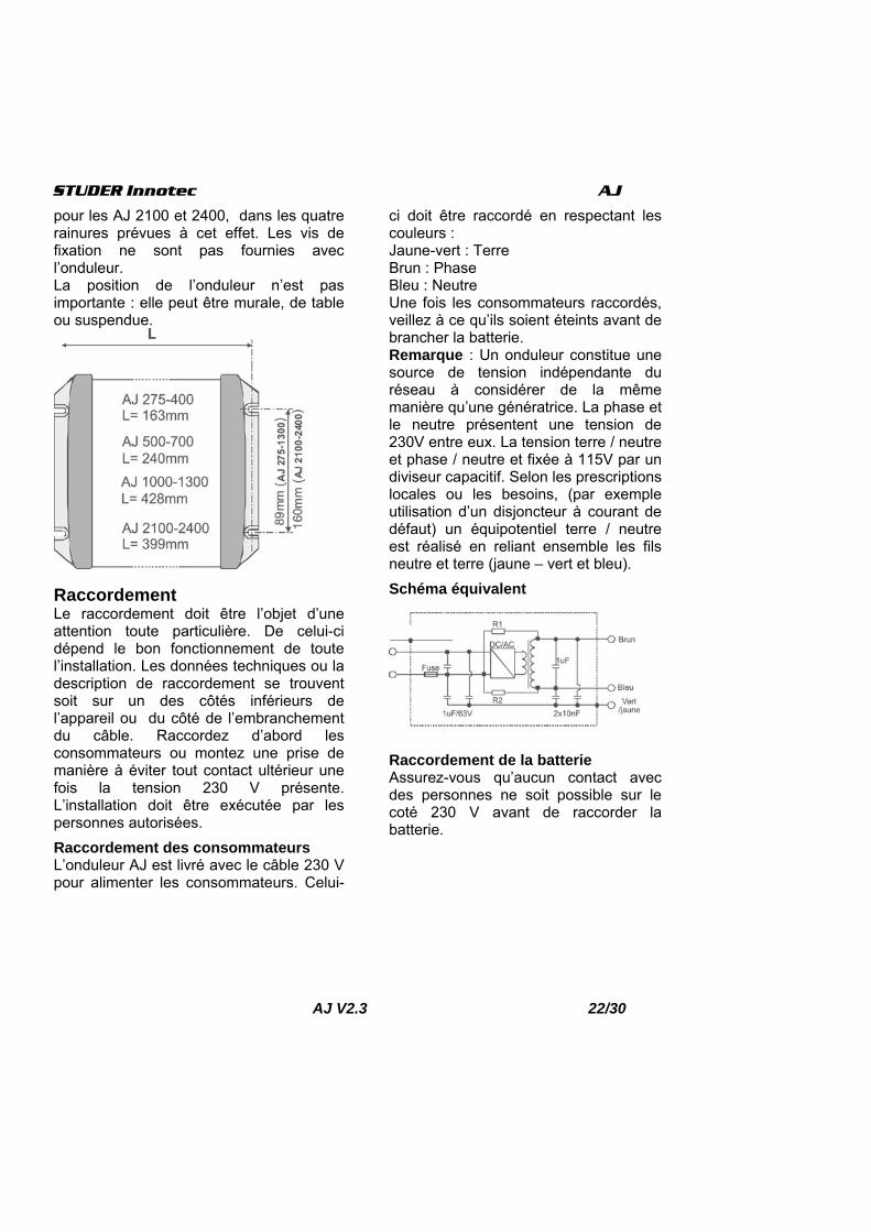
pour les AJ 2100 et 2400, dans les quatre rainures prévues à cet effet. Les vis de fixation ne sont pas fournies avec l’onduleur. La position de l’onduleur n’est pas importante : elle peut être murale, de table ou suspendue.
Raccordement Le raccordement doit être l’objet d’une attention toute particulière. De celui-ci dépend le bon fonctionnement de toute l’installation. Les données techniques ou la description de raccordement se trouvent soit sur un des côtés inférieurs de l’appareil ou du côté de l’embranchement du câble. Raccordez d’abord les consommateurs ou montez une prise de manière à éviter tout contact ultérieur une fois la tension 230 V présente. L’installation doit être exécutée par les personnes autorisées. Raccordement des consommateurs L’onduleur AJ est livré avec le câble 230 V pour alimenter les consommateurs. Celui-
ci doit être raccordé en respectant les couleurs : Jaune-vert : Terre Brun : Phase Bleu : Neutre Une fois les consommateurs raccordés, veillez à ce qu’ils soient éteints avant de brancher la batterie. Remarque : Un onduleur constitue une source de tension indépendante du réseau à considérer de la même manière qu’une génératrice. La phase et le neutre présentent une tension de 230V entre eux. La tension terre / neutre et phase / neutre et fixée à 115V par un diviseur capacitif. Selon les prescriptions locales ou les besoins, (par exemple utilisation d’un disjoncteur à courant de défaut) un équipotentiel terre / neutre est réalisé en reliant ensemble les fils neutre et terre (jaune – vert et bleu). Schéma équivalent
Raccordement de la batterie Assurez-vous qu’aucun contact avec des personnes ne soit possible sur le coté 230 V avant de raccorder la batterie.

STUDER Innotec AJ
AJ V2.3 23/30
Le câble de la batterie est livré avec l’onduleur et est déjà raccordé à l’intérieur de celui-ci. Raccordez la batterie en faisant très attention à la polarité. L’onduleur, est protégé de l’inversion de polarité par un fusible, à l’exception du AJ 2100-12. Cependant, si la polarité est inversée, l’onduleur doit être retourné en usine pour contrôle. Raccordez la batterie en utilisant les câbles aux couleurs suivantes : Câble NOIR : Pôle négatif (-) Câble ROUGE : Pôle positif (+). Pour AJ 275-350-400 appliquer la couleur dominante comme couleur de référence. En branchant la batterie il y a une étincelle (Danger d’explosion !), en raison du chargement du condensateur interne. Un fusible de sécurité incendie doit être monté sur la batterie. Vérifiez le serrage des câbles. Dans la mesure du possible ne rallongez pas les câbles de batteries fournis. Le fait de rallonger les câbles de batterie peut augmenter les pertes et provoquer un dysfonctionnement de l’onduleur. Une fois l’onduleur branché sur la batterie, la tension 230 V est présente à la sortie de l’onduleur.
Utilisation Commande et indicateurs Bouton de commande on/off Un bouton de commande est accessible sur l’onduleur. Il permet de l’enclencher ou de le déclencher. Utilisez cette fonction pour économiser l’énergie des batteries lorsque vous n’utilisez pas l’onduleur. Indicateur vert Un indicateur lumineux vert placé sur l’onduleur indique le mode de fonctionnement : Allumé : La tension 230 V est présente
à la sortie ; l’onduleur est en fonction. Clignotant :
_ _ _ : L’onduleur est en mode stand-by. __ __ __ : La tension 230 V est coupée momentanément suite à une alarme ; l’onduleur se remettra automatiquement en fonction dès que l’alarme aura disparu. (voir tableau des fautes ci-dessous)
Eteint : La tension 230 V n’est pas présente à la sortie ; l’onduleur est éteint.
Indicateur sonore L’onduleur AJ dispose d’un indicateur sonore qui signale les cas suivants :

STUDER Innotec AJ
AJ V2.3 24/30
Son intermittent : L’onduleur est en présence d’une faute et va couper la tension de sortie. Fautes possibles : Surchauffe : l’indicateur sonne 3°C avant
l’arrêt de l’onduleur. Diminuez la charge afin d’abaisser la température de l’onduleur et ainsi éviter l’arrêt.
Sous tension de batterie : l’indicateur sonne une minute avant la coupure. Si la tension de batterie remonte, la tension de sortie n’est pas coupée.
Son continu de deux secondes : Vous avez appuyé sur le bouton ON/OFF pour redémarrer l’onduleur. La tension de sortie est immédiatement présente à la sortie après le signal sonore.
Modèles avec stand-by Les onduleurs dès l’AJ 500-12 sont équipés d’un système stand-by. Le stand-by est un système d’économie d’énergie qui déclenche l’onduleur par intermittence lorsqu’aucun consommateur n’est détecté. Dans ce mode, l’indicateur lumineux vert clignote, indiquant la présence par intermittence de la tension. Cet ajustement se fait à l’aide d’un petit tournevis dans le trou marqué stand-by.
L’ajustement du niveau de détection s’effectue comme suit : éteindre tous les consommateurs, tourner le bouton rotatif vers la gauche (sens contraire des aiguilles d’une montre) jusqu’à que la LED clignote, allumer le plus petit consommateur (par ex. un chargeur pour tél. portable), tourner doucement le bouton rotatif vers la droite jusqu’à ce que la LED s’allume en continu. Contrôler que l’onduleur se mette en mode stand-by quand vous enlevez la charge. Sinon cela signifie que la charge est trop petite pour être détectée. Si le stand-by n’est pas souhaité, tourner le bouton complètement à droite. La puissance minimale détectée peut être ajustée entre 1 et 20 W. Dans la plupart des installations, ce réglage n’est pas utile. Le réglage se fait à l’aide d’un tournevis plat n°1 dans l’ouverture notée stand-by sur l’onduleur. Dans la position maximale à droite, la sensibilité est minimale (20 W). Ne pas appuyer sur le tournevis. ATTENTION : en fonctionnement stand-by le 230V est présent par intermittence à la sortie.

STUDER Innotec AJ
AJ V2.3 25/30
Sécurités L’onduleur AJ est protégé de manière électronique. Il est protégé contre les inversions de polarité par un fusible interne, à l’exception du modèle AJ 2100-12. Le tableau ci-dessous donne les divers cas possibles de faute et les conséquences.
FAUTE CONSEQUENCE RESOLUTION Tension de batterie basse <1,8V/élément
Onduleur stoppé momentanément, l’indicateur vert clignote.
Démarrage automatique dès que la tension de batterie sera remontée à 2V/élément.
Tension batterie <1,5V/élément
Onduleur stoppé indicateur vert éteint
Redémarrage manuel possible dès que la tension batterie est =/>2V/élément.
Surchauffe Onduleur stoppé momentanément, l’indicateur vert clignote.
Démarrage automatique dès que la température de l’appareil aura baissé.
Surtension de batterie
Onduleur stoppé Attendez que la tension de batterie soit à nouveau correcte. Une tension trop élevée peut détruire l’onduleur. Appuyez sur le bouton ON/OFF pour redémarrer l’onduleur.
Court-circuit en sortie
Onduleur stoppé Supprimez le court-circuit. Appuyez sur le bouton ON/OFF pour redémarrer l’onduleur.
Surcharge Onduleur stoppé Utilisez l’onduleur dans les limites de sa puissance nominale. Une utilisation prolongée ou régulière en surcharge diminuera sa durée de vie. Appuyer sur le bouton ON/OFF pour redémarrer l’onduleur.
Inversion de polarité de la batterie
Fusible interne détruit Retour en usine pour test.

STUDER Innotec AJ
AJ V2.3 26/30
Maintenance Les onduleurs de la série AJ ne nécessitent aucun entretien particulier. Le boîtier peut être nettoyé avec un chiffon humide (pas mouillé). Si un dysfonctionnement ou une déformation mécanique de la boite ou des câbles devait apparaître, l’onduleur doit être envoyé, soigneusement emballé dans son emballage d’origine, au fournisseur pour contrôle. Avant d’envoyer l’onduleur, veuillez contrôler les points ci-dessous. − La batterie est chargée et correspond à
la tension nominale d’entrée de l’appareil.
− Les consommateurs ne présentent aucun défaut ou surcharge pour l’onduleur. (Pour s’en assurer, débrancher les consommateurs).
Si toutefois vous devez prendre contact avec votre revendeur, veuillez noter les points suivants avant d’appeler : (vous trouverez ces indications sur l’étiquette au-dessous de l’onduleur ou du côté de l’embranchement du câble) − Le type exact de l’onduleur − Le numéro de série − La puissance de l’onduleur − La tension nominale d’entrée de
l’onduleur Avant l’envoi de l’onduleur, veillez qu’il soit bien emballé, l’onduleur doit être mis dans un carton rigide et être bien protégé de tous côtés ainsi que dessous, d’une couche d’isolante antichoc d’au moins 5cm d’épaisseur. Une mauvaise protection peut causer des dommages à l’onduleur lors du transport. Les dégâts causés lors du transport ne sont pas couverts par la garantie.
Exclusion de la garantie La garantie est de 2 ans. Elle ne couvre pas les cas de défauts survenus lors d’un usage non conforme à la description du manuel d’instructions ou non décrit par celui-ci, ou de tout autre usage inapproprié, notamment pour les onduleurs les événements suivants : − Inversion de la polarité sur l’entrée
batterie. − Tension inappropriée sur les entrées
(surtension). − Mise en contact de la sortie avec une
autre source de tension tel que réseau public ou générateur.
− Déformation mécanique. − Mise en contact avec un liquide ou
oxydation due à la condensation. Usage dans un environnement inadéquat. (poussière, vapeur corrosive, humidité, température élevée, etc.)
Exclusion de la responsabilité La pose, la mise en fonction, l’utilisation, la maintenance et le service ne peuvent pas faire l’objet d’une surveillance par la société STUDER INNOTEC. Pour cette raison, nous déclinons toute responsabilité pour les dommages, les coûts ou les pertes résultants d’une installation non conforme aux prescriptions, d’un fonctionnement défectueux ou d’un entretien déficient. L’utilisation des onduleurs STUDER INNOTEC relève dans tous les cas de la responsabilité du client. Cet appareil n’est pas conçu ni garanti pour l’alimentation d’installations destinées à supporter la vie ou toute autre installation critique comportant des risques potentiels de dégâts à l’homme ou à l’environnement. Nous n’assumons

STUDER Innotec AJ
AJ V2.3 27/30
en outre aucune responsabilité pour les violations de droits de brevets ou d’autres droits de tiers résultant de l’utilisation de l’onduleur.
STUDER INNOTEC se réserve le droit de toute modification sur les produits sans communication préalable.
J T8 Commande à distance pour AJ 1000-2400 Les fonctions de la télécommande sont les mêmes que les fonctions disponibles sur l’onduleur. (Voir chapitre Utilisation) La télécommande doit être raccordée à l’onduleur à l’aide du câble d’origine STUDER (10m) ou tout autre câble RJ11/6p 1:1 jusqu’à une longueur max. de 50m.

STUDER Innotec AJ
AJ V2.3 28/30
Données techniques MODELE AJ 275 AJ 350 AJ 400 AJ 500 AJ 600 AJ 700 Tension de batterie (V) 12 24 48 12 24 48 Tension d’entrée (V) 10.5-
16 21-32 42-64 10.5-
16 21-32 42-64
Puissance continue/30’ (VA) 200/275 300/350 300/400 400/500 500/600 500/700 Stand-by / ON à vide (W) 0.3*/1.
9 0.3*/3.
3 0.4*/5 0.3/3.8 0.4/8.5 1/10
Rendement maximal en (%) 93 94 94 93 94 94 Dim. 142 x 84 x L (mm) L= 163 252 Poids en (kg) 2.4 2.6 4.5 Commande à distance RCM-01 Option Option Détection (Stand-by) 1 à 20 W avec option S oui Chargeur solaire (option S) 10A 15A MODELE AJ 1000 AJ 1300 AJ 2100 AJ 2400 Tension de batterie (V) 12 24 12 24 Tension d’entrée (V) 10.5 - 16 21 - 32 10.5 - 16 21 - 32 Puissance continue/30’ (VA) 800/1000 1000/1300 2000/2100 2000/2400 Stand-by / ON à vide (W) 0.3 / 9 0.4 / 10 0.5 / 13 0.4 /18 Rendement maximal en (%) 93 94 92 94 Dim. 142 x 84 x L (mm) L= 428 273 x 399 x 117 Poids en (kg) 8.5 19 18 Télécommande (JT8) Option Option Détection (Stand-by) 1 à 20 W oui oui Chargeur solaire (option S) 25A 30A Tension de sortie Sinus 230V 0/-10% (115V 0/-10%) Fréquence 50 Hz +/- 0.05 % (60 Hz +/-0.05%) Ventilation Dès 45° C Protection thermique oui Protection surcharge oui Protection court-circuit oui (fusible) Degré de protection IP IP 30 (AJ 2100-2400 = IP 20) Cos φ 0.1-1 Norme E (ECE-R 10) Tous les modèles en 12 et 24V sont certifiés * Stand-by avec option -S (régulateur solaire)

STUDER Innotec AJ
AJ V2.3 29/30
Modèles avec chargeur solaire (option – S) Le régulateur de charge à disposition dans l’onduleur AJ est destiné exclusivement à la charge de la batterie par des modules photovoltaïques. Toute autre source de courant nécessite l’usage d’un régulateur de charge adapté à cette source. La tension à vide des modules solaires doit être de 23V maximum pour les applications 12V, de 46V maximum pour les applica-tions 24V, et de 90V maximum pour les applications 48V. Le mode de réglage est de type I/U/Uo ("floating") à découpage shunt et garanti des conditions de charge
optimales pour la durée de vie de la batterie. L’indicateur jaune indique le mode de fonctionnement: Allumé : La charge solaire est maximale. Eteint : Le générateur solaire n’est pas
branché ou la batterie est complètement chargée ou le module photovoltaïque n’est pas illuminé.
Clignotante : La batterie est chargée à plus de 95 % et le chargeur est en mode floating pour compléter la charge (la fréquence de clignotement varie en fonction de la capacité de batterie et de la puissance du générateur solaire).
Raccordement des modules sur AJ 2100/2400-S : Pour les onduleurs AJ 2100/2400-S, le connecteur d’entrée des modules solaires est remplacé par un câble (2 x 6mm2) préinstallé. Le raccordement se fait via une boîte de dérivation. Positif (+) sur le fil brun ou rouge Négatif (-) sur le fil bleu ou noir
STUDER Innotec AJ
AJ V2.3 30/30
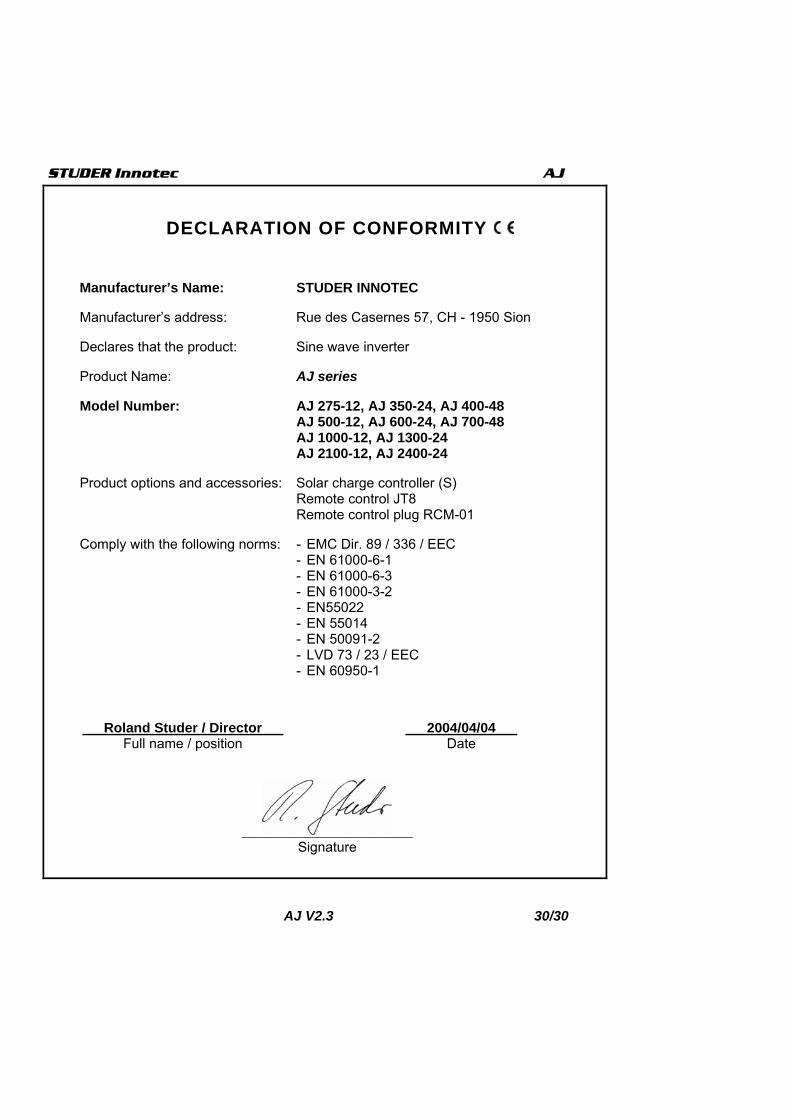
DECLARATION OF CONFORMITY
Manufacturer’s Name: STUDER INNOTEC
Manufacturer’s address: Rue des Casernes 57, CH - 1950 Sion
Declares that the product: Sine wave inverter
Product Name: AJ series
Model Number: AJ 275-12, AJ 350-24, AJ 400-48 AJ 500-12, AJ 600-24, AJ 700-48 AJ 1000-12, AJ 1300-24 AJ 2100-12, AJ 2400-24
Product options and accessories: Solar charge controller (S) Remote control JT8 Remote control plug RCM-01
Comply with the following norms: - EMC Dir. 89 / 336 / EEC - EN 61000-6-1 - EN 61000-6-3 - EN 61000-3-2 - EN55022 - EN 55014 - EN 50091-2 - LVD 73 / 23 / EEC - EN 60950-1
…..Roland Studer / Director….. …..2004/04/04….. Full name / position Date
….. ….. Signature