Embed Size (px)
Citation preview

For internal use only / © Siemens AG 2012. All Rights Reserved.
SINAMICS V20
… the cost-effective, reliable and easy-to-use inverter for basic applications
© Siemens AG 2013. All Rights Reserved.
Summary
Applications Support
Customer benefits
Tools
Commissioning
Communication
Functions
Product
Introduction
SINAMICS V20

© Siemens AG 2013. All Rights Reserved.Industry SectorPage 3
SINAMICS V20 – Making the choice easy for you
SINAMICS V20The cost-effective, reliable and easy-to-use inverter for basic applications
Easy to install
Easy to use
Easy to save money

© Siemens AG 2013. All Rights Reserved.Industry SectorPage 4
Field of applications
V20
Fiel
d of
app
licat
ions

© Siemens AG 2013. All Rights Reserved.Industry SectorPage 5
Fields of application and product positioning
Fiel
d of
app
licat
ion
V20

© Siemens AG 2013. All Rights Reserved.
Summary
Applications Support
Customer benefits
Tools
Commissioning
Communication
Functions
Product
Introduction
SINAMICS V20

© Siemens AG 2013. All Rights Reserved.Industry SectorPage 7
Siemens Numerical Control Ltd., Nanjing (SNC)
Zero-Defect Culture and continuous improvement for perfect quality
SNC is a top ranking supplier for machine tool systems and factory automation
Development and production of SINAMICS V20
HMI’s
PLC’s
Numerical Control Systems
Drives
© Siemens AG 2013. All Rights Reserved.Industry SectorPage 8
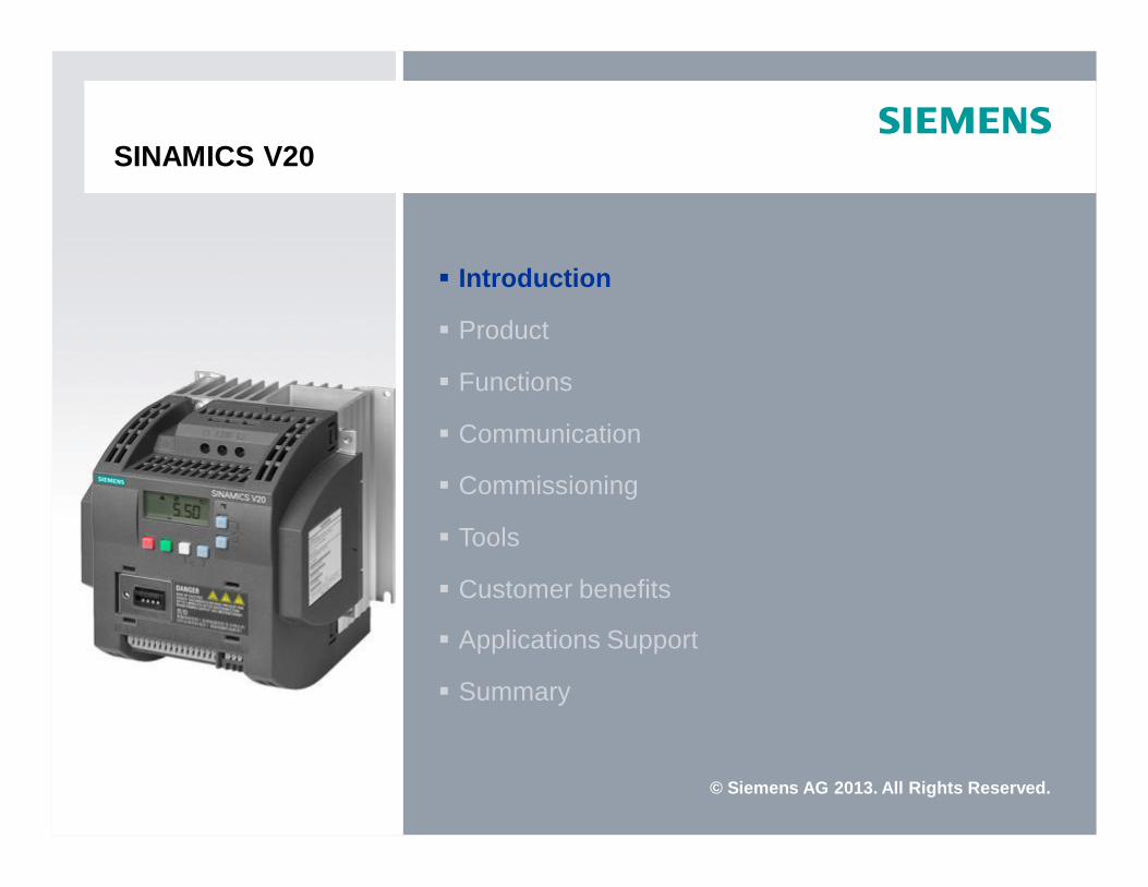
Production of Motion Control products
Surface Mounting Wave Soldering PCB Testing Coating & Glue
Module AssemblyOut-of-Box test Module testPacking
Modern Production Lines Integrated Testing Well Trained Work Force

© Siemens AG 2013. All Rights Reserved.Industry SectorPage 9
SINAMICS V20 Overview
Leistungsbereich: 0,12 kW – 15 kWVoltage range: 1 AC 230V / 3 AC 400VBetriebsart: U/f U2/f FCC
Easy to installPush-through and wall mounting possible in parallelUSS and MODBUS RTU on terminalsIntegrated braking chopper from 7.5kW
Easy to useParameter loading without power supplyApplication and connection macros for quick commissioning“Keep running mode” for uninterrupted operation also with unstable power supplyWider voltage range, advanced cooling design and coated PCBs and electronic components increase the robustness
Easy to save moneyECO mode with automatic flow reduction with U/f, U2/fHibernation mode to reduce the energy consumption in standby modeEnergy consumption display
Power Range: 0.12 kW – 15kWVoltage Range: 1AC 230V / 3AC 400VControl Mode: V/f V2/f FCC

© Siemens AG 2013. All Rights Reserved.Industry SectorPage 10
Dimensions
FSA FSB FSC FSD
Frame sizeWidth[mm]
Height[mm]
Depth[mm]
Weight*[kg]
W1 W2 H1 H2 H3 D
FSA 90 79 166 140 150 145.5 1.05
FSB 140 127 160 135 - 164.5 1.8
FSC 184 170 182 140 - 169 2.6
FSD 240 223 206.5 166 - 172.5 4.3
* with integrated line filter

© Siemens AG 2013. All Rights Reserved.Industry SectorPage 11
Technical specifications
Power and ControlVoltage 3AC 380V … 480V (-15% … +10%)
1AC 200V … 240V (-10% … +10%)Input frequency 50/60 HzSupply network TN, TT, IT, TT earthed line Power range 3AC 400V 0.37… 15.0 kW
1AC 230V 0.12…3.0 kWOverload 150% rated output current for 60 sOutput frequency 0.. 599 Hz resolution: 0.01 Hz Pulse frequency 2…16 kHzControl methods Linear V/F, quadratic V/F, multi-point V/F, flux current control
Signal inputs and outputsAnalog inputs AI1: bipolar curent / voltage mode
AI2: unipolar current / voltage modeCan be used as digital inputs
Analog outputs AO: 0…20mADigital inputs DI1-DI4, optically isolated
PNP/NPN selectable by terminal Digital outputs DO1: transistor output
DO2: relay output250 V AC 0.5 A with inductive load30 V DC 0.5 A with ohmic load
Mounting and environmentDegree of protection IP20Mounting Wall-mounting with side-by-side
push-through mounting for FSB, C and DCooling FSA less than 1.1kW: natural cooling.
FSA, FSB, FSC, FSD: cooling of power electronics via heat sinks with external fan
Ambient temperature
Operation: 0…+60 °C (32…140 °F) ; 40…60°C(104…40°F) with derating
Storage: -40 ... + 70 °C (-40 ... 158°F) Relative humidity 95 % (non-condensing) Altitude Up to 4000m above sea level
1000... 4000 m: output current derating2000 ... 4000 m: input voltage derating
Motor cable length Unshielded cable: 50mShielded cable: 25m; 10m for FSA filtered version.
Dynamic braking Option for FSA, FSB and FSC; integrated for FSD
StandardsStandards CE, cULus, c-Tick, KC
EMC standards
3AC 400VEN 61800-3 Category C3: ESD, Radiated immunity, Burst, Surge, Conducted immunity, Voltage distortion immunity
1AC 230VEN 61800-3 Category C2 Conducted Emissions, Radiated Emissions

© Siemens AG 2013. All Rights Reserved.Industry SectorPage 12
Integrated Basic Operating Panel (BOP)
• Full control of the motor via the integrated BOP
• Easy menu structure for quick commissioning
• The LED shows directly the actual inverter status
• Graphical display• Values and Units• Status icons
• The international layout can be easily operated by users from every countryAuto/Manual/Jog mode
FunctionStart
Stop
Up
Reverse
Down
Status icons
Units
Status LED
OK

© Siemens AG 2013. All Rights Reserved.Industry SectorPage 13
External BOP
Use the external BOP and be more flexible in operating SINAMICS V20 …
Remote control on the inverter via ext. BOP, e.g. door connection. The BOP interface with SD/MCC slot can also be used for parameter loading, storing or cloning
3 m
Convenient and intuitive navigation with wheel control
Interface with SD/MMC slot for parameter cloning
The drive can be conveniently operated from outside the cabinet
Simple installation on the cabinet door

© Siemens AG 2013. All Rights Reserved.Industry SectorPage 14
Options
Braking module
Shortens the deceleration ramp timeSuitable for 1 AC 230 V and 3 AC 400 VDuty cycle adjustable from 5 % to 100 %FSD devices with integrated braking unit
External BOP (Basic Operator Panel)
BOP interface:Connection between inverter and ext. BOPIntegrated SD/MMC card slot for parameter loading /storing / cloning
V20 BOP:Same functions as the integrated BOPThe values and setpoints are changed by rotating the wheel
BOP cable: 3 m cable with connectors
Parameter loader
Loading and storing resp. cloning of parameter setsThe converter need not be connected to the power supplyMax. 100 parameters sets can be managed on one memory card

© Siemens AG 2013. All Rights Reserved.Industry SectorPage 15
Options
Braking resistor Line filter
Output reactors Line reactor
Reduction of harmonics
Improves the power factor
FSA, .. , D
To implement EMC-conforming installations
Allow longer motor cables
Dissipates regenerative energy as heat
Graduated for FSA, ..., D
© Siemens AG 2013. All Rights Reserved.Industry SectorPage 16
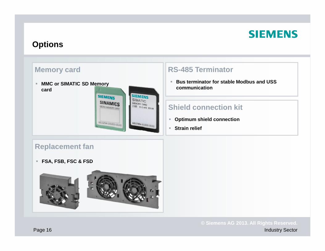
Options
RS-485 Terminator
Replacement fan
Memory card
MMC or SIMATIC SD Memory card
Bus terminator for stable Modbus and USS communication
FSA, FSB, FSC & FSD
Shield connection kitOptimum shield connection
Strain relief

© Siemens AG 2013. All Rights Reserved.Industry SectorPage 17
Packaging
Delivery includes …
SINAMICS V20
Getting started guide
Certificate
Software licenses
Save transport and storage Cushioning material absorbs impacts and strengthens the box to resist transportation under rough condition
Compact inverter …… compact package
Frame sizeWidth[mm]
Height[mm]
Depth[mm]
FSA 143 218 198
FSB 203 223 226
FSC 262 260 242
FSD 318 286 252

© Siemens AG 2013. All Rights Reserved.Industry SectorPage 18
System overview
V20 BOP(Basic Operator Panel)
Braking resistor,,large(FSD)
Brakingmodule(FSA, FSB, FSC)
Linereactor
Linefilter
Outputreactor
Parameter loader
BOP (Basic Operator Panel)interface
SD/MMCMemory card
Shieldconnection kit
Braking resistor,small(FSA, FSB, FSC)
Comprehensive options…

© Siemens AG 2013. All Rights Reserved.Industry SectorPage 19
System overview
V20 BOP(Basic Operator Panel)
Braking resistor,,large(FSD)
Brakingmodule(FSA, FSB, FSC)
Linereactor
Linefilter
Outputreactor
Parameter loader
BOP (Basic Operator Panel)interface
SD/MMCMemory card
Shieldconnection kit
Braking resistor,small(FSA, FSB, FSC)
Comprehensive options…
Robustness
Braking
Easy to use

© Siemens AG 2013. All Rights Reserved.
Summary
Applications Support
Customer benefits
Tools
Commissioning
Communication
Functions
Product
Introduction
SINAMICS V20
© Siemens AG 2013. All Rights Reserved.Industry SectorPage 21
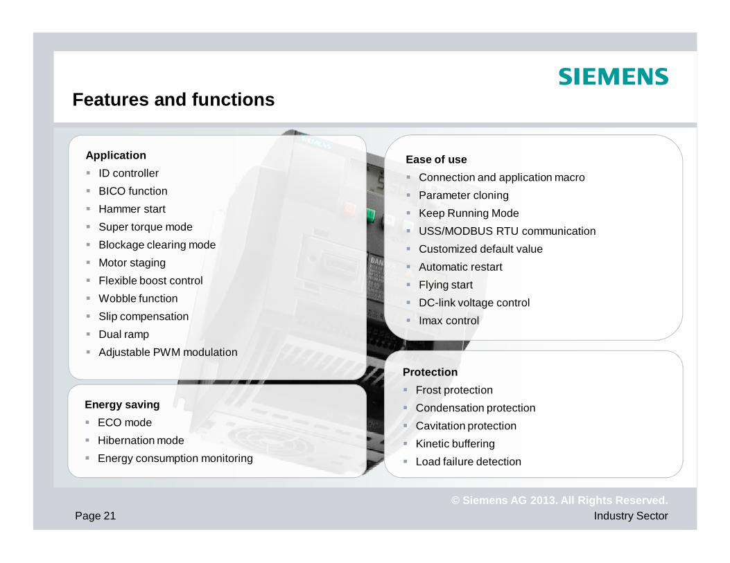
Features and functions
ApplicationID controllerBICO functionHammer startSuper torque modeBlockage clearing modeMotor stagingFlexible boost controlWobble functionSlip compensationDual ramp Adjustable PWM modulation
Ease of useConnection and application macroParameter cloningKeep Running ModeUSS/MODBUS RTU communicationCustomized default value Automatic restartFlying start DC-link voltage control Imax control
ProtectionFrost protectionCondensation protectionCavitation protectionKinetic bufferingLoad failure detection
Energy savingECO modeHibernation modeEnergy consumption monitoring

© Siemens AG 2013. All Rights Reserved.
Summary
Applications Support
Customer benefits
Tools
Commissioning
Communication
Functions
Product
Introduction
SINAMICS V20

© Siemens AG 2013. All Rights Reserved.Industry SectorPage 23
Communication
Wiring diagramUser terminal2 analog inputs1 analog output4 digital inputs2 digital outputs
Communication.Integrated communication interface for USS and MODBUS RTU, additional modules are not required.Setpoints can also be specified via the analog inputIntegrated communication macrosThe automation system can be conveniently set up via the standardized libraries in the PLC
Easy to use terminalSimply plug in, no special tool requiredThe terminal designations are engraved

© Siemens AG 2013. All Rights Reserved.Industry SectorPage 24
Communication
USS® - Protocol
The USS® protocol is a simple serial data transfer protocol for the drives technology defined by Siemens AG.Major features oft the USS® protocol are:
Support of a multi-point-capable coupling, e.g. EIA RS 485-Hardware, or point to point coupling e.g. EIA RS 232Master slave access technique, single master system, maximum 32 nodes (31 slaves)Baud rate 2,4 – 187,5kbit/sCable length maximum 1200m (3300ft)Operation with either variable or fixed telegram lengthsSame bus physic as PROFIBUS (DIN 19245 Teil 1)Data interface to the basic unit according profile “Variable Speed Drives”. Information to the drive with USS®
protocol are transmitted the same way as PROFIBUS-DPThe USS® protocol can be implemented on industrial controller and on PC’s. SIMATIC S7 200 and S7 1200 support the protocol as standard. Building automation systems Desigo PX with additional I/O module have implemented the protocol as well.Further information:http://support.automation.siemens.com/WW/view/en/24178253

© Siemens AG 2013. All Rights Reserved.Industry SectorPage 25
Communication
Modbus RTUModbus is a serial communications protocol published by Modicon in 1979 for use with its programmable logic controllers (PLCs). The Modbus protocol is a communication protocol based on a Master-Slave or Client/Server architecture. The main reasons for the extensive use of Modbus in the industrial environment are:
It has been developed with industrial applications in mind It is openly published and royalty-free It is easy to deploy and maintain It moves raw bits or words without placing many restrictions on vendors
Modbus RTU (Remote Terminal Unit) is the most common implementation available for Modbus. It transmits data in serial communication and makes use of a compact, binary representation of the data for protocol communication.
Support of a multi-point-capable coupling, e.g. EIA RS 485-Hardware, or point to point coupling e.g. EIA RS 232Master slave access technique, single master system, maximum 247 slavesBaud rate 4,8 – 187,5kbit/sCable length maximum 1200m (3300ft)Since the Modbus protocol can only handle register or bit numbers for addressing the memory, assignment to the appropriate control words, status words and parameters is performed on the slave side.

© Siemens AG 2013. All Rights Reserved.
Summary
Applications Support
Customer benefits
Tools
Commissioning
Communication
Functions
Product
Introduction
SINAMICS V20

© Siemens AG 2013. All Rights Reserved.Industry SectorPage 27
Macro-based commissioning of the V20 – with a fews stepsfrom the first startup through to the running motor
SINAMICS V20 –Easy to set up, easy to use
Power on
Confirm / changemotor data
1
Start motor
General parametersettings
4
DI 1 – ON / OFFDI 3 – DC Braking (option)AI 1 Speed set-point
M
DI 1 Digital OutputDrive Running
Analogue OutputSpeed *
DI 3
10V
0V
AI
3
Speedset-point
3 AC Supply
* Optional. Not required Note: Analog input DIP switch,Set to V unless a “constant current” source
I V DI 1 – ON / OFFDI 3 – DC Braking (option)AI 1 Speed set-point
M
DI 1 Digital OutputDrive Running
Analogue OutputSpeed *
DI 3
10V
0V
AI
3
Speedset-point
3 AC Supply
* Optional. Not required Note: Analog input DIP switch,Set to V unless a “constant current” source
I V
Note: Analog input DIP switch,Set to V unless a “constant current” source
I V
MDI 1 – ON / OFFDI 2 – Speed upDI 3 – Speed down
DI 1 Digital OutputDrive Running *
Analogue OutputSpeed *
DI 2DI 3
3
3 AC Supply
* Optional. Not required
MDI 1 – ON / OFFDI 2 – Speed upDI 3 – Speed down
DI 1 Digital OutputDrive Running *
Analogue OutputSpeed *
DI 2DI 3
3
3 AC Supply
* Optional. Not required
* Optional. Not required
BOP – ON / OFFBOP – Speed upBOP – Speed downM
Digital OutputDrive Running *
Analogue OutputSpeed *
3 AC Supply
3
* Optional. Not required
BOP – ON / OFFBOP – Speed upBOP – Speed downM
Digital OutputDrive Running *
Analogue OutputSpeed *
3 AC Supply
3
Selectconnection macro
2Select
application macro
DI 1 – ON / OFFDI 2 – Fixed speed 1DI 3 – Fixed speed 3
* Optional. Not required
M
DI 1 Digital OutputDrive Running *
Analogue OutputSpeed *
DI 2DI 3
3
3 AC Supply
DI 1 – ON / OFFDI 2 – Fixed speed 1DI 3 – Fixed speed 3
* Optional. Not required
M
DI 1 Digital OutputDrive Running *
Analogue OutputSpeed *
DI 2DI 3
3
3 AC Supply
DI 1 – ForwardDI 2 – ReverseDI 3 - DC Braking (option)AI – Speed Set-point
* Optional. Not required
M
DI 1 Digital OutputDrive Running *
Analogue OutputSpeed *
DI 2DI 3
0VAI
3
3 AC Supply
“PNP”PLC outputs
PLC
Note: Analog input DIP switch,Set to V unless a “constant current” source
I V
DI 1 – ForwardDI 2 – ReverseDI 3 - DC Braking (option)AI – Speed Set-point
* Optional. Not required
M
DI 1 Digital OutputDrive Running *
Analogue OutputSpeed *
DI 2DI 3
0VAI
3
3 AC Supply
“PNP”PLC outputs
PLC
Note: Analog input DIP switch,Set to V unless a “constant current” source
I V
Note: Analog input DIP switch,Set to V unless a “constant current” source
I V
DI 1 – ON / OFFDI 2 – Local / RemoteDI 3 – DC Braking (option)
* Opt ional. Not required
M
DI 1 Digital OutputDrive Running *
Analogue OutputSpeed *
DI 2
DI 3
3
3 AC Supply
DI 1 – ON / OFFDI 2 – Local / RemoteDI 3 – DC Braking (option)
* Opt ional. Not required
M
DI 1 Digital OutputDrive Running *
Analogue OutputSpeed *
DI 2
DI 3
3
3 AC Supply
3
© Siemens AG 2013. All Rights Reserved.Industry SectorPage 28
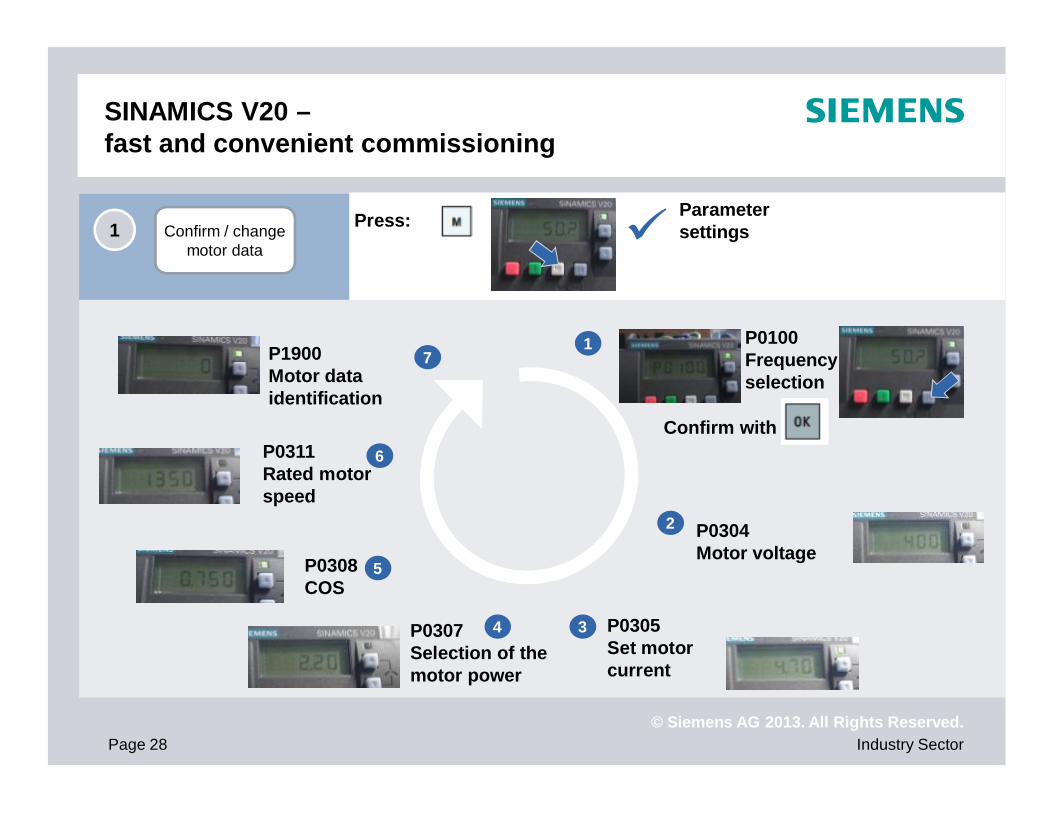
SINAMICS V20 –fast and convenient commissioning
Confirm / changemotor data
1 Press: Parametersettings
P0100 Frequencyselection
Confirm with
P0304 Motor voltage
P0305 Set motor current
P0307Selection of themotor power
P0308COS
P0311 Rated motorspeed
P1900 Motor dataidentification
1
2
34
5
6
7

© Siemens AG 2013. All Rights Reserved.Industry SectorPage 29
SINAMICS V20 –fast and convenient commissioning
Selectconnection macro
2
Selection of the connection macros
E.g. Cn010 USS controller
Press: Parametersettings
Cn001 BOP as single control source
Minus shows the current macro selection
© Siemens AG 2013. All Rights Reserved.Industry SectorPage 30
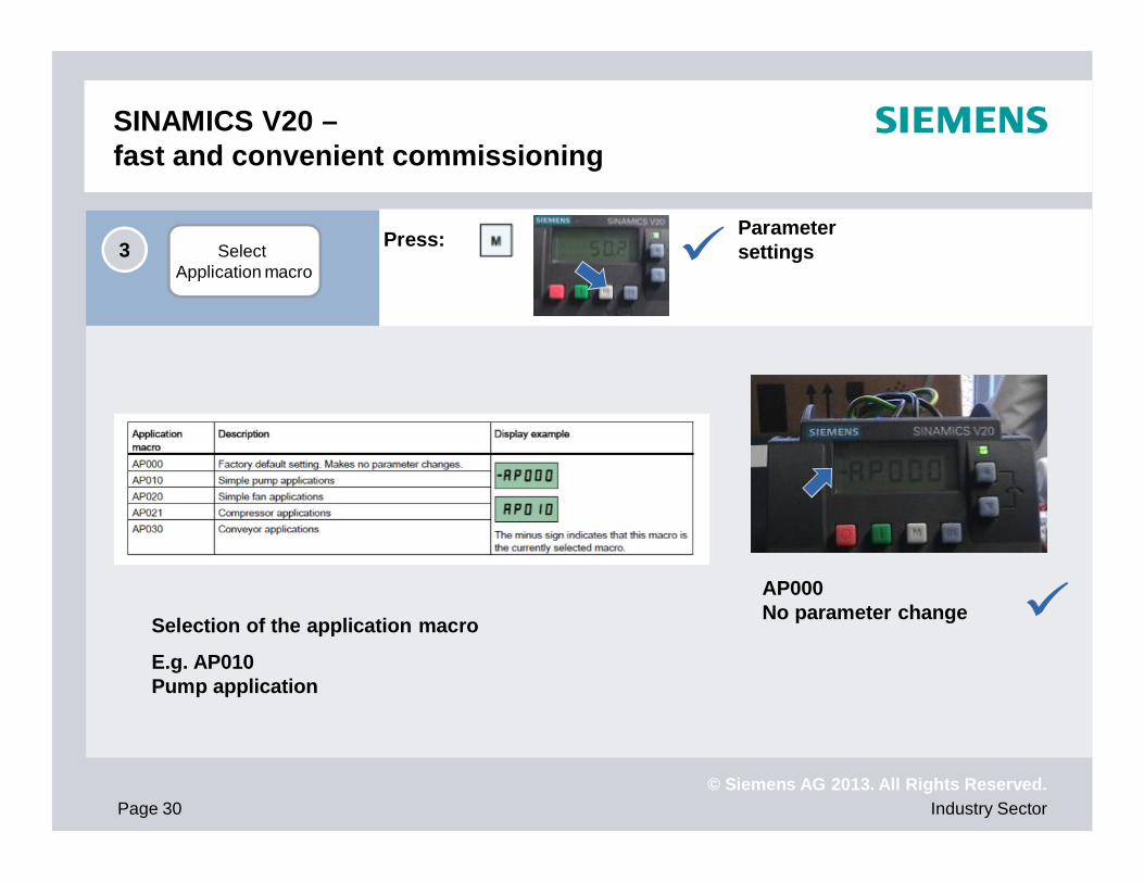
SINAMICS V20 –fast and convenient commissioning
Select Application macro
3
Selection of the application macro
E.g. AP010 Pump application
AP000 No parameter change
Press: Parametersettings

© Siemens AG 2013. All Rights Reserved.Industry SectorPage 31
SINAMICS V20 –fast and convenient commissioning
General parametersettings
4
Selection of the application macro
E.g. P1120 Set ramp-up time
Press: Parametersettings
P2248 Ramp-down time motor potentiometer Technology controller

© Siemens AG 2013. All Rights Reserved.
Summary
Applications Support
Customer benefits
Tools
Commissioning
Communication
Functions
Product
Introduction
SINAMICS V20

© Siemens AG 2013. All Rights Reserved.Industry SectorPage 33
DT Configurator
Configuration
Selection of drives based on the application matrixeven without any experts knowledgeDelivery of optimized SINAMICS drives suitable to requirements2D/3D-Modells, operating instructions, data sheetsSupport for the following Order processhttps://eb.automation.siemens.com/goos/catalog/Pages/ProductData.aspx?regionUrl=/de&language=de&tree=CatalogTree&nodeid=10028832&autoOpenConfigId=10&kmat=DT_M#topAnch

© Siemens AG 2013. All Rights Reserved.
Summary
Applications Support
Customer benefits
Tools
Commissioning
Communication
Functions
Product
Introduction
SINAMICS V20

© Siemens AG 2013. All Rights Reserved.Industry SectorPage 35
Energy efficiency Macro-based commissioning and development for operation in harsh environments.
The energy consumption is significantly reduced thanks to the energy-saving functions.
SINAMICS V20 – Easy to install, easy to use and easy to save money!
Easy to USE
Easy to SAVE MONEY
Easy to INSTALL
The cost-effective, reliable and easy to use inverter for basic applications
Flexibility and easy integration in existing systems.
Productivity
Compact

© Siemens AG 2013. All Rights Reserved.Industry SectorPage 36
Easy to install
Flexibility and easy integration in existing systems.
InstallationSide-by-side, push-through and wall mounting.
Compact design and flexible installation.
Communication
Braking modulePossible to use dynamic braking to increase thebraking performance. Simply connect the braking
resistor to the built-in braking module (>=7.5 kWh).
USS and Modbus RTU selectable.
Easy integration in existing systems. Connection macros and standard libraries support commissioning.

© Siemens AG 2013. All Rights Reserved.Industry SectorPage 37
Easy to use
Macro-based commissioning and robustness for operation in harsh environments.
Macro approachOptimized application settings for quick commissioning.
Parameter cloning
Robustness
Keep Running ModeHigher productivity in production by automatic adjustment in the case of unstable line supplies.
Wider voltage range, improved cooling design and coated PCBs increase the robustness of the drive.
Easy transfer of parameter settings from one inverter to another.

© Siemens AG 2013. All Rights Reserved.Industry SectorPage 38
Easy to save money
Integrated energy saving functions for reduction of the energy consumption.
ECO ModeMachine setting according to the relevant application and adjustment of the current flow to save energy.
DC coupling
Hibernation ModeIntegrated energy saving functions for standby mode.
Re-use regenerative energy across multiple inverters.

© Siemens AG 2013. All Rights Reserved.Industry SectorPage 39
Very simple connection to an automation system
…
SINAMICS V20SIMATIC PLCSIMATIC Panel
USSMODBUS RTU
Ethernet/PROFINET .…
Saving time and minimizing errorsBasic system configuration with standardized PLC libraries and predefined macros in the inverter
One cable to connect SINAMICS V20 with USS or MODBUS RTU
Integrated communication interface
© Siemens AG 2013. All Rights Reserved.
Summary
Applications Support
Customer benefits
Tools
Commissioning
Communication
Functions
Product
Introduction
SINAMICS V20

© Siemens AG 2013. All Rights Reserved.Industry SectorPage 41
Target applications
Belt conveyorsRoller conveyorsChain conveyors
Centrifugal pumpsRadial/axial fansCompressors
Single drives in the process industrysuch as mills, mixers, kneaders, crushers, agitators, centrifuges
Main drives in machines with mechanically coupled axessuch as ring spinning machines, braiding machines for textile, ropes and wire
Moving
Pumping, ventilating and compressing
Processing

© Siemens AG 2013. All Rights Reserved.Industry SectorPage 42
Target applications
Additional advantagesCentrifugal pumpsRadial/axial fansCompressors
High availability through automatic restart and flying restart after power failures
Broken belt detection by monitoring the load torque
Pump protection against cavitation
Hammer start and blockage clearing modes for clogged pumps
PID controller for process values (e.g. temperature, pressure, level, flow)
PID auto tuning to optimize controller parameters
Hibernation mode stops the motor when demand is small
Motor staging extends the flow range by adding two more fixed-speed drives (cascade)
Frost and condensation protection prevent moisture in motors under extreme environmental conditions
Belt conveyorsRoller conveyorsChain conveyors
Soft, jerk-free acceleration reduces the stress on the gear units, bearings, drums and rollersSuper torque start for conveyor belts with high breakaway torqueDynamic behavior by using braking resistor or DC brakingDirect control of mechanical holding brake
Single drives in the process industry such as mills, mixers, kneaders, crushers, agitators, centrifugesMain drives in machines with mechanically coupled axes such as ring spinning machines, braiding machines for textile, ropes and wire
Frost and condensation protection prevent moisture in motors under extreme environmental conditionsHigher productivity with uninterrupted production due to “don’t tell me” modeExchange of regenerative energy via the DC linkSuper torque start for machines with a high breakaway torque
Pum
ping
, ven
tilat
ing
and
com
pres
sing
Mov
ing
Proc
essi
ng

© Siemens AG 2013. All Rights Reserved.Industry SectorPage 43
Tough environment –Ceramic tile production line
SINAMICS V20 was successfully tested in tough environment
Simple and crude shop floorConstantly high temperatures over 40°CCeramic dust all over the shop floor24h / 7days production

© Siemens AG 2013. All Rights Reserved.Industry SectorPage 44
Tough environment –Textile environment
SINAMICS V20 was successfully tested in tough environment
Oil traces on machines and in the airCotton fiber all over the shop floorUnstable power supplyHigh humidity level (over 75%) and temperatures over 25°C

© Siemens AG 2013. All Rights Reserved.Industry SectorPage 45
Long term outdoor running test
SINAMICS V20 resisted long term climate changes. And the outdoor running test will go on …

© Siemens AG 2013. All Rights Reserved.Industry SectorPage 46
The machine cuts one or two long adhesive tape rolls into rolls of the preset width.
One motor drives one or two rotating shafts on which the adhesive tape rolls are located. The other one rotates the cutter knife to increase the cutting force.
A PLC controls the movement and speed of the two drive motors.
Automatic cutting machine
First customer successesEasy to install & easy to use
Machining
When the cutter knife touches the conveyor belt, the load torque quickly increases. V20 keeps the speed stable.
V20 has a more compact design and allows the use of other products without modifying the cabinet.
V20 provides user-friendly connection terminals. All control terminals can be easily inserted and need not be screwed in.
RollerDI:FWD & REVAI: Frequency
Cutterknife
V20
V20
HMI
PLC
3.7 kW
1.5 kW
4 kW
2.2 kW

© Siemens AG 2013. All Rights Reserved.Industry SectorPage 47
First customer successes Easy to use
The sealing system fixes caps on bottles. The machine is an integral part of the production line.
The cycle sequence is set at the BOP. All commands are issued by the data input terminal. The user requires an external emergency stop.
Sealing system / Food and Beveragesector
Transport
DI1
DI2
DI3
DI4
DIC24V
0V
DO1+
DO1-
On/Off
Ext. release
Error acknow.
Jog
220V
V20
We have only selected the connection macro Cn002 and set P702=29. Convenient wiring and parameter setting for quick commissioning.
2.2 kW2.2 kW Gearbox

© Siemens AG 2013. All Rights Reserved.Industry SectorPage 48
The machine performs surface grinding on lacquered wooden flooring.
One motor drives the grinder rollers, which rotates the abrasive belt in one direction. The other motor drives the conveyor belt which controls the feedrate via a stepless gearbox.
All position switches are connected to a special controller which controls the movements of the abrasive and conveyor belts.
Competitor: Delta-B
Grinding machine
First customer successes Easy to use
Machining
3AC380V 0.75kW 6-pole
SINAMICSV20
The terminals of the V20 for connection to the controller are easy to handle.
Position switch
Start/Stop

© Siemens AG 2013. All Rights Reserved.
Summary
Applications Support
Service and Logistics Support
Customer benefits
Tools
Commissioning
Communication
Functions
Product
Introduction
SINAMICS V20

© Siemens AG 2013. All Rights Reserved.Industry SectorPage 50
Energy efficiency
SINAMICS V20 The new compact drive is …
Easy to use
Easy to save money
Easy to install
The cost-efficient, reliable and easy to use converter for basic applications
Productivity
Compact
… perfectly tailored to meet your requirements ….
… well thought-out & provides all the Basics you need!
The perfect drive for basic requirements
Top price level
1 MLFB, complete functionality
Perfect for large quantities
Short delivery time
Service: 24-month warranty period

© Siemens AG 2013. All Rights Reserved.
Thank you for your attention!