Embed Size (px)
Citation preview
www.elsevier.com/locate/cviu
Computer Vision and Image Understanding 102 (2006) 1–21
Simultaneous tracking of multiple body parts of interacting persons
Sangho Park *, J.K. Aggarwal
Computer and Vision Research Center, Department of Electrical and Computer Engineering, University of Texas at Austin, Austin, TX 78712, USA
Received 18 October 2003; accepted 18 July 2005Available online 14 November 2005
Abstract
This paper presents a framework to simultaneously segment and track multiple body parts of interacting humans in the presence ofmutual occlusion and shadow. The framework uses multiple free-form blobs and a coarse model of the human body. The color imagesequence is processed at three levels: pixel level, blob level, and object level. A Gaussian mixture model is used at the pixel level to trainand classify individual pixel based on color. Relaxation labeling in an attribute relational graph (ARG) is used at the blob level to mergethe pixels into coherent blobs and to represent inter-blob relations. A twofold tracking scheme is used that consists of blob-to-blobmatching in consecutive frames and blob-to-body-part association within a frame. The tracking scheme resembles multi-target, multi-association tracking (MMT). A coarse model of the human body is applied at the object level as empirical domain knowledge to resolveambiguity due to occlusion and to recover from intermittent tracking failures. The result is �ARG–MMT�: �attribute relational graphbased multi-target, multi-association tracker.� The tracking results are demonstrated for various sequences including �punching,��hand-shaking,� �pushing,� and �hugging� interactions between two people. This ARG–MMT system may be used as a segmentationand tracking unit for a recognition system for human interactions.� 2005 Elsevier Inc. All rights reserved.
Keywords: Tracking; Body part; Human interaction; Occlusion; ARG; MMT
1. Introduction
Video surveillance of human activity requires reliabletracking of moving human bodies. Tracking non-rigidobjects such as moving humans presents several difficultiesfor computer analysis. Problems include segmentation ofthe human body into meaningful body parts, handlingthe occlusion of body parts, and tracking the body partsalong a sequence of images. Many approaches have beenproposed for tracking a human body (see [1–3] for reviews).The approaches for tracking a human body may be classi-fied into two broad groups: model-based approaches andappearance-based approaches.
Model-based approaches use a priori models explicitlydefined in terms of kinematics and dynamics. The bodymodel is fitted to an actual shape in an input image.
1077-3142/$ - see front matter � 2005 Elsevier Inc. All rights reserved.
doi:10.1016/j.cviu.2005.07.011
* Corresponding author. Fax: +1 512 471 5532.E-mail addresses: [email protected] (S. Park), aggar-
[email protected] (J.K. Aggarwal).
Various fitting algorithms are used with motion constraintsof the body model. Examples include 2D models such asthe stick-figure model [4] and cardboard model [5], and3D models such as the cylinder model [6] and super-ellip-soid model [7]. 3D models can be acquired with either mul-tiple cameras or a single camera [8,9]. Difficulties withmodel-based approaches lie in model initialization, efficientfitting to image data, occlusion, and singularity involved ininverse kinematics.
Appearance-based approaches use heuristic assump-tions on image properties when no a priori model isavailable. Image properties include pixel-based propertiessuch as color, intensity, and motion, or area-based proper-ties such as texture, gradient, edge, and neighborhoodareas. Appearance-based approaches aim at maintainingand tracking those image properties along the imagesequence. Examples include edge-based methods such asenergy minimization [10], sampling-based methods suchas Markov chain Monte Carlo estimation [11], area-basedmethods [12,13], and template-based methods [14]. Some

2 S. Park, J.K. Aggarwal / Computer Vision and Image Understanding 102 (2006) 1–21
approaches may combine model-based methods withappearance information [15,16].
Most of the methods that use a single camera assumeexplicitly or implicitly that there is no significant occlusionbetween tracked objects. To date, research has focused ontracking a single person in isolation [17,13], or on trackingonly a subset of the body parts such as head, torso, hands,etc. [18]. Research on segmentation or tracking of multiplepeople has focused on the analysis of the whole body interms of the silhouettes [19,14], contours [20,21], color[22], or blob [13,23].
The objective of this paper is to present a method forsegmentation and tracking of multiple body parts in a bot-tom-up fashion. The method is a bottom-up approach inthe sense that individual pixels are grouped into homoge-neous blobs and then into body parts. The tracks of thehomogeneous blobs are automatically generated and multi-ple tracks are maintained across the video sequence.Domain-knowledge about the human body is introducedat the high-level processing stage.
We propose an appearance-based method for combiningthe attribute relational graph and data association amongmultiple free-form blobs in color video sequences. The pro-posed method can be effectively used to segment and trackmultiple body parts of interacting humans in the presenceof mutual occlusion and shadow. In this paper, we addressthe problem of segmenting multiple humans into semanti-cally meaningful body parts and tracking them under theconditions of occlusion and shadow in indoor environ-ments. This is a difficult task for several reasons. First,the human body is a non-rigid articulated object that hasmany degrees of freedom (DOF) in its articulation. Precisemodeling of the human body would require expensive com-putation. Model-based approaches often require manualinitialization of the body model. Second, loose clothingintroduces irregular shape deformation. Silhouette- or con-tour-based approaches are sensitive to noise in shape defor-mation. Third, occlusion and shadow are inevitablein situations that involve multiple humans. Self-occlusionoccurs between different body parts of a person, whilemutual occlusion occurs between different persons in thescene. Image data is severely hampered by occlusion andshadows, making it difficult to segment and track bodyparts. Multiple-view approaches are often introduced toovercome the occlusion and shadow effects. But multiple-view approaches are not applicable in widely available sin-
New Image
Back ground
Back groundSubtraction
Pixel-colorClassification
RelaxLabe
Fig. 1. System
gle-camera video data. High-level domain knowledge mayalso be used to infer the body-part relations underocclusion.
The proposed system processes the input imagesequence at three levels: pixel level, blob level, and semanticobject level. A Gaussian mixture model is used to classifyindividual pixels into several color classes. Relaxationlabeling with attribute relational graph (ARG) is used tomerge the color-classified pixels into coherent blobs of arbi-trary shape according to similarity features of the pixels.The multiple blobs are then tracked by data associationusing a variant of the multi-target, multi-association track-ing (MMT) algorithm used by Bar-Shalom et al. [24].Unmatched residual blobs are tracked by inference at theobject level using a body model as domain knowledge. Acoarse body model is applied as empirical domain knowl-edge at the object level to assign the blobs to appropriatebody parts. The blobs are then grouped to form the mean-ingful body parts by the simple body model. Using the sim-ple human-body model as a priori knowledge helps toresolve ambiguity due to occlusion and to recover fromintermittent tracking failure. The result is �ARG–MMT�:�attribute relational graph based multi-target, multi-associ-ation tracker.�
Fig. 1 shows the overall system diagram of theARG–MMT. At each frame, a new input image is com-pared with a Gaussian background model. The back-ground subtraction module produces the foregroundimage. Pixel-color clustering produces initial blobsaccording to pixel color. Relaxation labeling merges theinitial blobs on a frame-by-frame basis. Multiblob track-ing associates the merged blobs in the current frame withthe track history of the previous frame and update thehistory for the current frame. Body-part assignmentassigns the tracked blobs to the appropriate human bodyparts. The body-pose history of the previous frame isincorporated as domain knowledge about the humanbody. The assigned body parts are recursively updatedfor the current frame.
The rest of the paper is organized as follows. Section 2describes the procedure at the pixel level, Section 3describes the blob formation, Section4 presents a methodto track multiple blobs, while Section 5 describes the seg-mentation and tracking of semantic human body parts.Experiments and conclusions follow in Sections 6 and 7,respectively.
Multi-blobTracking
Body partsSegmentatation
Body poseHistory
TrackHistory
upda
te
upda
te
ationling
diagram.

Fig. 2. Examples of an input image frame (A) and its foregroundimage (B).
S. Park, J.K. Aggarwal / Computer Vision and Image Understanding 102 (2006) 1–21 3
2. Pixel clustering
2.1. Color representation and background subtraction
Most color cameras provide an RGB (red, green, andblue) signal. The RGB color space is, however, not effectiveto model chromaticity and brightness independently. In thisresearch, the RGB color space is transformed to the HSV(hue, saturation, value) color space to make the intensityor brightness explicit and independent of the chromaticity.
Background subtraction is performed in each frame tosegment the foreground image region. The color distribu-tion of each pixel v (x,y) at image coordinate (x,y) is mod-eled as a Gaussian
vðx; yÞ ¼ ½vHðx; yÞ; vSðx; yÞ; vVðx; yÞ�T. ð1ÞSuperscript T denotes the transpose throughout this paper.The mean lZ (x,y) and standard deviation rZ (x,y) of pixelintensity at every location (x,y) of the background modelis calculated for each color channel Z 2 {H,S,V} using kb
training frames (kb = 20) that are captured when no personappears in the camera view. The number of training frameskb was determined by experimental trials, in which we usedkb values of 15, 30, 60, and 90 frames for background sub-traction and obtained very similar results. We used 20 back-ground frames, since from a statistical viewpoint, 20 isregarded as the minimum number of samples for reliablecomputation of mean and covariance. Foreground segrega-tion is performed for every pixel (x,y), by using a simplebackground model, as follows: at each image pixel (x,y) ofa given input frame, the change in pixel intensity is evaluatedby computing the Mahalanobis distance from the Gaussianbackground model dZ (x,y) for each color channel Z
dZðx; yÞ ¼jvZðx; yÞ � lZðx; yÞj
rZðx; yÞ. ð2Þ
The foreground image F (x,y) is defined by the maximumof the three distance measures, dH, dS, and dV for the H,S, and V channels
F ðx; yÞ ¼ max½dHðx; yÞ; dSðx; yÞ; dVðx; yÞ�. ð3ÞF is then thresholded to make a binary mask image. Thethreshold value of the foreground image is determined bytraining in background subtraction. We used a backgroundsubtraction method similar to the one in [25]. In general,low threshold values produce larger foreground regionsand more background noise, while high threshold valuesproduce smaller foreground regions with possible holesand less background noise. A major portion of the back-ground noise is singleton pixels, and the number of single-ton pixels is a good indicator of overall background noisemisclassified as foreground pixels. Our approach is to ap-ply low threshold values first and then to refine the preli-minary foreground area by adjusting the initial thresholdto reduce the number of singleton pixels in the foreground.We assume an indoor setting where the ambient light is sta-ble. We also assume that the persons appear at some dis-
tance from the camera to make sure the whole bodies ofthe interacting persons are included in the camera view.Under these conditions, the threshold value does not varysignificantly according to the colors in the foregroundscenes, number of people, or distance from the camera.We trained the threshold value through experimental trials,and the same threshold value was used for all experiments.If the setting changes from one place to another with differ-ent lighting conditions, we need to re-train the system.
After the background subtraction, morphological oper-ations are performed as a post-processing step to removesmall regions of noise pixels. Fig. 2 shows an example ofan input image and its foreground-segmented image.
2.2. Gaussian mixture model for color distribution
In HSV space, the color values of a pixel at location(x,y) are represented by a random variable v = [vH, vS,vV]T
with a vector dimension d = 3. According to the method in[26], the color distribution of a foreground pixel v is mod-eled as a mixture of C0 Gaussians weighted by prior prob-ability P (xr), given by
pðvÞ ¼XC0
r¼1
pðvjxrÞP ðxrÞ; ð4Þ
where the rth conditional probability is assumed as aGaussian, as follows:
pðvjxrÞ ¼ ð2pÞ�d=2jRrj�1=2
� exp �ðv� lrÞTR�1
r ðv� lrÞ2
" #; r ¼ 1; . . . ;C0. ð5Þ
Each Gaussian component hj represents the prior prob-ability P (xr) of the rth color class xr, a mean vector lr ofthe pixel color component, and a covariance matrix Rr ofthe color components; hj = {lj,Rj,C0,P(xj)}. To obtainthe Gaussian parameters, an EM algorithm ([26]) is usedas follows. We can obtain the estimates P ðxiÞ, li, and Ri
for P(xi), li, and Ri, respectively, by the following iterativemethod (Eqs. (6)–(8)) [26].
P ðxiÞ 1
n
Xn
k¼1
P ðxijvk; hÞ; ð6Þ
li Pn
k¼1Pðxijvk; hÞvkPnk¼1P ðxijvk; hÞ
; ð7Þ
4 S. Park, J.K. Aggarwal / Computer Vision and Image Understanding 102 (2006) 1–21
Xi
Pn
k¼1P ðxijvk; hÞðvk � liÞðvk � liÞTPn
k¼1P ðxijvk; hÞ; ð8Þ
where
P ðxijvk; hÞ pðvkjxi; hiÞPðxiÞPcj¼1pðvkjxj; hjÞP ðxjÞ
. ð9Þ
Initialization (E-step) of the Gaussian parameters is doneas follows. We start the iterations Eqs. (6)–(8) with the ini-tial guess with the first g frames of the sequence as thetraining data (g = 5). Definitely, using more frames to trainthe mixture of Gaussian parameters produces better esti-mation, but the expectation–maximization (EM) algorithmwould take a significantly longer time with more frames.We determined the number of training frames g by exper-imental trials. All prior probabilities are assumed as equal.
P ðxrÞ ¼1
C0
. ð10Þ
The mean is randomly chosen from a uniform distributionwithin a possible pixel value range in each color channel{H,S,V}.
lr ¼ ½vH; vS; vV�T;where vH 2 ½minðvHÞ;maxðvHÞ�vS 2 ½minðvSÞ;maxðvSÞ�vV 2 ½minðvVÞ;maxðvVÞ�.
ð11Þ
The covariance matrix is assumed to be an identity matrix.
Rr ¼ I; rankðIÞ ¼ 3. ð12ÞTraining (M-step) is performed by iteratively updating theabove mentioned parameters according to Eqs. (6)–(8)([26]). The iteration stops when the change in the valueof the means is less than 1% compared to the previous iter-ation or when a user-specified maximum iteration number,f, is exceeded (f = 20). The training depends on the initialguess of the Gaussian parameters. We start with 10 Gauss-ian components (C0 = 10) and merge similar Gaussiansafter the training by the method in [27], resulting in CGaussians (See Appendix B for the merging process.) Theparameters of the established C Gaussians are then usedto classify pixels into one of the C classes in subsequentframes.
2.3. Pixel color clustering
The Gaussians obtained by the EM algorithm are repre-sented in terms of the iso-surface ellipsoids in a multi-di-mensional space. Our Gaussian model is three-dimensional, correspond to hue, saturation, and value inthe HSV color space. The color clustering of the individualforeground pixels is achieved by a maximum a posteriori(MAP) classifier (Eq. (13)). We compute the MAP proba-bility P (xr|v) for all pixels v and for all classes r. The classlabel xL is assigned to the pixel v as its class if xL producesthe largest MAP probability, as follows:
xL ¼ arg maxr logðP ðxrjvÞÞ; 1 6 r 6 C. ð13Þ
3. Blob formation
3.1. Initial blob formation
The pixel color clustering process labels the foregroundpixels with the same color as being in the same class, eventhough they are not connected. In an ideal situation, onlythe pixels connected to each other would be labeled asbeing in the same class. Therefore, we have to relabelthe pixels with different classes if they are disconnectedin an image. The connected component analysis is usedto relabel the disjoint blobs, if any, with distinct labels,resulting in over-segmented small regions. The numberof disjoint blobs generated by the relabeling processmay vary from frame to frame depending on the inputimage. The fluctuation of blob numbers causes difficulty.To maintain consistency, we have to merge the over-seg-mented regions into meaningful and coherent blobs. Thisrequires a high-level image analysis that takes intoaccount the relationship between the segmented regions.The motivation behind choosing to assemble the blobsin two steps rather than include pixel location as partof the classification process is as follows; if the classifica-tion includes pixel location, then the classifier can confusethe pixel membership class, when one person�s body partstretches across another person�s body part. This causes aproblem especially when the two persons interact in closeproximity with their body parts occluding each other.Therefore, we first assemble and track the blobs basedon color and a blob-adjacency constraint, and then asso-ciate the tracked blobs with body model. In the followingsections, we discuss how the neighborhood relations ofthe pixels are exploited to achieve coherent homogeneousimage regions.
3.2. Attribute relational graph for blob relations
We use image features based on contours andregions, which are more descriptive than pixels. Suchfeatures are not only described by the properties ofthe features themselves but are also related to oneanother by relationships between them. The attributerelational graph (ARG) has been used for labeling fea-tures. The relational structure R in the ARG model isspecified by node set S, neighborhood system N, anddegree of relationship D.
R ¼ ðS;N ;DÞ; ð14Þ
where S corresponds to the set of blobs, N the adjacencylist for the blobs, and D the degree of the relationships,which includes unary, binary, and tertiary features. Fig. 3shows an example of an ARG. We use tertiary blob-fea-tures (D = 3) as the highest level of abstraction to describethe characteristics of the jth blob, Aj, as follows:

C
AD B
E
FG
B
DE
C
F
B
C
A
E
F
Bolb attributes:sizecolorlocation
border ratioshapeorientation
perimeter
G
A
A B C D
Fig. 3. Attribute relational graph (ARG). (A) image patch surrounding blob A, (B) relational graph for blob A in which solid arrows show binaryrelations and dotted arrows show tertiary relations, (C) border area of blob A in gray, and (D) blob attributes that describe blob features.
S. Park, J.K. Aggarwal / Computer Vision and Image Understanding 102 (2006) 1–21 5
1. Unary features: determined by a single blob• Blob label: L(Aj) 2 Z+= {natural numbers}• Blob size: a(Aj) = |Aj|, where |qj is the number of pixel
elements in the blob q.• Color: [lH,lS,lV]T, the mean intensities of H, S, V col-
or components of the blob.• Blob position: ½�I ; �J �T, the median position of the blob
(i.e., the median values of horizontal and vertical pr-ojections of the blob in spatial coordinates).
• Border pixel set: W (Aj)W (Aj) = {8-connected outer-most pixels corresponding to the contour of Aj}.
2. Binary features: determined by two adjacent blobs• Adjacency list: C (Aj) = {k 2 Z+|Ak is adjacent to
Aj,k „ j}.• Border-ratio of Aj with respect to Ak: bj (Ak) = (num-
ber of pixels in W (Aj) connected to Ak)/|W (Aj)|.
3. Tertiary features: determined by three blobs• Tertiary relation between Aj and Ai: s (Aj,Ai)
sðAj;AiÞ ¼1 if Aj 2 CðCðAiÞÞ; j 6¼ i;
0 otherwise.
�
4. We include the following skin predicate:• Skin predicate: 1 (Aj)
1ðAjÞ ¼1 ifððT H1 6 lH 6 T H2Þ ^ ðT S1 6 lS 6 T S2ÞÞ for Aj;
0 otherwise.
�
The thresholds TH1, TH2, TS1, and TS2 are determined asfollows. We assumed that the environment was indoor withfluorescent light, and we determined the threshold valuesmanually from training data. A group of persons of differ-ent gender, ethnicity, and age was used to obtain the train-ing data. We observe that the skin color thresholds, TH1,TH2, TS1, and TS2, are robust to illumination variation,but the threshold values are sensitive to different lightsources such as sunlight, tungsten light and fluorescentlight. If the environment changes with different lightsource, we need to re-train the threshold values. Skin infor-mation is very useful in recognizing body parts. Skin coloris determined by a single melanin pigment, and only itsdensity differs between different ethnic groups. We adopta simple threshold model for skin color detection using
the chromaticity channels H and S in the HSV color space.The values of the thresholds TH1, TH2, TS1, and TS2
obtained from the training data are used to segment theskin regions in the new frames.
3.3. Relaxation labeling for blob merging
Merging over-segmented blobs is a region growingprocedure [28] controlled by the local consistency imposedby the ARG formulation. Two blobs are merged by thefollowing criteria; blobs Ai and Aj are merged only if thefollowing blob-merging criteria are satisfied.
1. Adjacency criterion: two blobs should be adjacent.2. Border-ratio criterion: two blobs should share a large
border. (bi (Aj) P Tb) � (bj (Ai) P Tb); Tb is a threshold.3. Color similarity criterion: two blobs should be similar in
color, where the similarity is defined by the Mahalanobisdistance dU of color feature U between the blobs Ai andAj, as follows:
dU ¼ ðUi � UjÞTðRUÞ�1ðUi � UjÞ; ð15Þ
U ¼ ½lH; lS; lV�T; ð16Þ
where RU is the covariance matrix of color values for all theblobs in the image. If dU is less than a threshold TU, blobsAi and Aj are similar in color.4. Tertiary relation criterion: if Aj is a skin blob and if Aj is
adjacent to a single blob Ak that is again nested by a sin-gle blob Ai, then regard Ai as being adjacent to Aj:([1 (Aj) = 1] � [C (Aj) = Ak] � [C (Ak) = Ai]) fi letC (Aj) = Ai.
5. Small blob criterion: A small blob less than a thresholdTa surrounded by a single large blob larger than Ta ismerged to it.
6. Skin blob criterion: a skin blob does not follow the smallblob criterion but instead follows the tertiary relationcriterion, which is useful to handle the color smeararound skin blobs caused by the fast motion of theblobs.
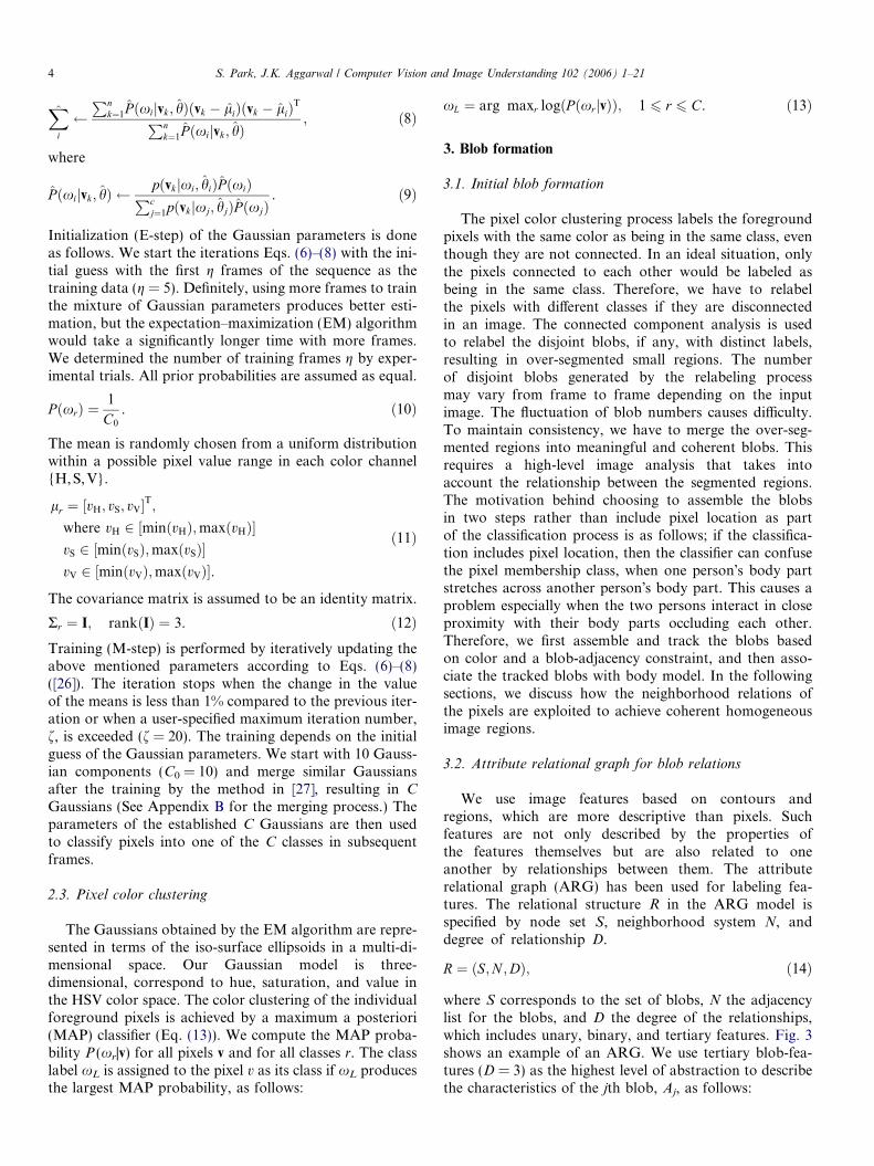
Figs. 4–8 illustrate the process of the relaxation labelingbased on the blob-merging criteria.
Fig. 4 shows an example of initial blobs correspondingto an image patch from Fig. 2B. Fig. 5 represents the attri-bute relational graph (ARG) corresponding to Fig. 4 for allblobs. (See Fig. 3 for the details of the ARG for blob A.)
A
C
F
E
D B G
Fig. 4. Initial blobs in an image patch.
B C
F A D
E G
Fig. 5. Initial ARG corresponding to Fig. 4. Solid lines represent binaryrelations, while dotted lines show tertiary relations.
B C
F A D
E G
B C
F A D
E G
A B
Fig. 6. Blob similarity in terms of blobs D (A) and G (B) in Fig. 5.Arrowed lines represent similar blobs.
B C
F A D
E G
Fig. 7. Merge graph representing the overall blobs similarity in Fig. 4.
A FG
E
BD
C
Fig. 8. Similar blobs from Fig. 4 have been merged according to the mergegraph in Fig. 7.
Fig. 9. Comparison example of pixel-color clustering (A) and itsrelaxation labeling (B).
6 S. Park, J.K. Aggarwal / Computer Vision and Image Understanding 102 (2006) 1–21
Solid lines in Figs. 5–7 represent binary relations, whiledotted lines show the tertiary relations between the blobs.If two blobs satisfy the blob-merging criteria, then amerge-relation is established between the two blobs.
Fig. 6 represents the established merge-relations for blobsD and G, respectively. Arrowed lines in Figs. 6 and 7 rep-resent to-be-merged blobs. Note that most of the merge-re-lations are established for binary relations. Fig. 7 shows themerge graph that represents the overall merge-relations forthe image patch in Fig. 4. Note that blobs B–D are to bemerged together, and blobs E–G are to be merged together.Fig. 8 shows the result of the relaxation labeling for Fig. 4according to the merge graph in Fig. 7.
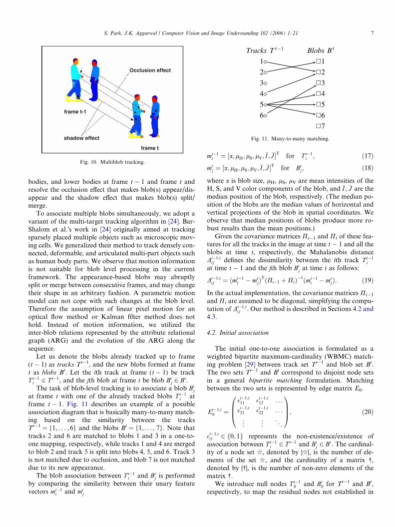
Fig. 9 compares the pixel-color clustering and its relax-ation labeling. Different colors represent different labels.The pixel-color clustering results (Fig. 9A) contain irregu-lar speckle noises due to lighting reflection (around hairand shoulders), color hollow effects (around faces andhands), and shadows (around hips, legs, and lower arms).The relaxation labeling results of blob merging (Fig. 9B)resolve most of the noise artifacts. Some noisy large blobs(as in the hip area of the left person) may remain.
4. Tracking multiple blobs
4.1. Multi-target, multi-association strategy for tracking
blobs
Tracking multiple blobs across a video sequenceinvolves the following problems:
1. A different number of blobs may be involved at eachtime frame.
2. A single blob at time t � 1 may split into multiple blobsat time t due to shadowing or occlusion, etc.
3. Multiple blobs at time t � 1 may merge into a singleblob at time t due to overlap or occlusion, etc.
4. Some blobs at time t � 1 may disappear at time t.5. New blobs may appear at time t.
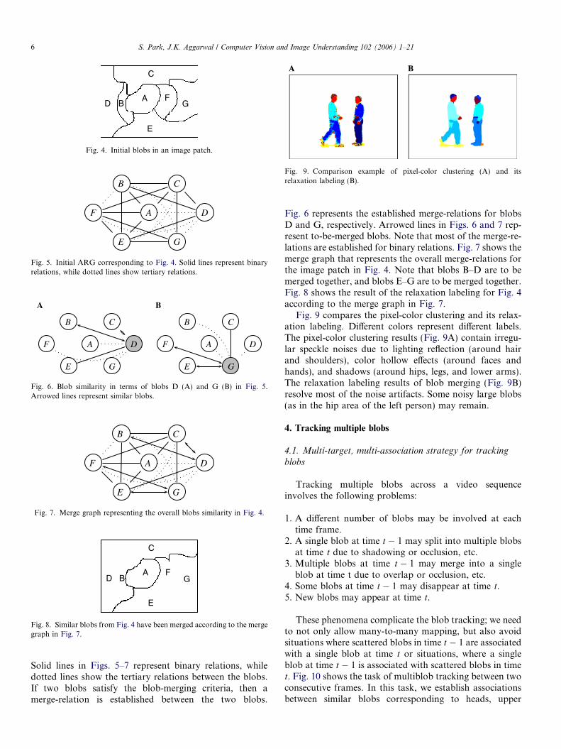
These phenomena complicate the blob tracking; we needto not only allow many-to-many mapping, but also avoidsituations where scattered blobs in time t � 1 are associatedwith a single blob at time t or situations, where a singleblob at time t � 1 is associated with scattered blobs in timet. Fig. 10 shows the task of multiblob tracking between twoconsecutive frames. In this task, we establish associationsbetween similar blobs corresponding to heads, upper
1 1
2 2
3 3
4 4
5 5
6 6
7
Tracks T Blobs B
Fig. 11. Many-to-many matching.shadow effect
Occlusion effect
frame t-1
frame t
Fig. 10. Multiblob tracking.
S. Park, J.K. Aggarwal / Computer Vision and Image Understanding 102 (2006) 1–21 7
bodies, and lower bodies at frame t � 1 and frame t andresolve the occlusion effect that makes blob(s) appear/dis-appear and the shadow effect that makes blob(s) split/merge.
To associate multiple blobs simultaneously, we adopt avariant of the multi-target tracking algorithm in [24]. Bar-Shalom et al.�s work in [24] originally aimed at trackingsparsely placed multiple objects such as microscopic mov-ing cells. We generalized their method to track densely con-nected, deformable, and articulated multi-part objects suchas human body parts. We observe that motion informationis not suitable for blob level processing in the currentframework. The appearance-based blobs may abruptlysplit or merge between consecutive frames, and may changetheir shape in an arbitrary fashion. A parametric motionmodel can not cope with such changes at the blob level.Therefore the assumption of linear pixel motion for anoptical flow method or Kalman filter method does nothold. Instead of motion information, we utilized theinter-blob relations represented by the attribute relationalgraph (ARG) and the evolution of the ARG along thesequence.
Let us denote the blobs already tracked up to frame(t � 1) as tracks Tt�1, and the new blobs formed at framet as blobs Bt. Let the ith track at frame (t � 1) be trackT t�1
i 2 T t�1, and the jth blob at frame t be blob Btj 2 Bt.
The task of blob-level tracking is to associate a blob Btj
at frame t with one of the already tracked blobs T t�1i at
frame t � 1. Fig. 11 describes an example of a possibleassociation diagram that is basically many-to-many match-ing based on the similarity between the tracksTt�1 = {1, . . . , 6} and the blobs Bt = {1, . . . , 7}. Note thattracks 2 and 6 are matched to blobs 1 and 3 in a one-to-one mapping, respectively, while tracks 1 and 4 are mergedto blob 2 and track 5 is split into blobs 4, 5, and 6. Track 3is not matched due to occlusion, and blob 7 is not matcheddue to its new appearance.
The blob association between T t�1i and Bt
j is performedby comparing the similarity between their unary featurevectors mt�1
i and mtj
mt�1i ¼ ½a; lH; lS; lV;�I ; �J �
T for T t�1i ; ð17Þ
mtj ¼ ½a; lH; lS; lV;�I ; �J �
T for Btj; ð18Þ
where a is blob size, lH, lS, lV are mean intensities of theH, S, and V color components of the blob, and �I , �J are themedian position of the blob, respectively. (The median po-sition of the blobs are the median values of horizontal andvertical projections of the blob in spatial coordinates. Weobserve that median positions of blobs produce more ro-bust results than the mean positions.)
Given the covariance matrices Pt�1 and Pt of these fea-tures for all the tracks in the image at time t � 1 and all theblobs at time t, respectively, the Mahalanobis distanceDt�1;t
ij defines the dissimilarity between the ith track T t�1i
at time t � 1 and the jth blob Btj at time t as follows:
Dt�1;tij ¼ ðmt�1
i � mtjÞ
TðPt�1 þPtÞ�1ðmt�1i � mt
jÞ. ð19Þ
In the actual implementation, the covariance matrices Pt�1
and Pt are assumed to be diagonal, simplifying the compu-tation of Dt�1;t
ij . Our method is described in Sections 4.2 and4.3.
4.2. Initial association
The initial one-to-one association is formulated as aweighted bipartite maximum-cardinality (WBMC) match-ing problem [29] between track set Tt�1 and blob set Bt.The two sets Tt�1 and Bt correspond to disjoint node setsin a general bipartite matching formulation. Matchingbetween the two sets is represented by edge matrix E0.
Et�1;t0 ¼
�t�1;t11 �t�1;t
12 . . .
�t�1;t21 �t�1;t
22 . . .
..
. ... . .
.
0BB@
1CCA; ð20Þ
�t�1;tij 2 f0; 1g represents the non-existence/existence of
association between T t�1i 2 T t�1 and Bt
j 2 Bt. The cardinal-ity of a node set q, denoted by |q|, is the number of ele-ments of the set q, and the cardinality of a matrix �,denoted by |�|, is the number of non-zero elements of thematrix �.
We introduce null nodes T t�10 and Bt
0 for Tt�1 and Bt,respectively, to map the residual nodes not established in

Tracks T Blobs B
1 1
2 2
3 3
4 4
5 5
6 6
7
Fig. 12. Intermediate results of initial one-to-one matching for Fig. 11.
Fig. 13. One-to-one association for Tt�1 and Bt. The dotted line denotesthat 1Tt�1 and 1Bt are one-to-one associated, while 0Tt�1 ˝ Tt�1 and0Bt ˝ Bt are unmatched residuals.
8 S. Park, J.K. Aggarwal / Computer Vision and Image Understanding 102 (2006) 1–21
the one-to-one association. Therefore the null track (i = 0)may be associated with multiple blobs and the null blob(j = 0) may be associated with multiple tracks.
Et�1;t ¼�00 �01 �02 . . .
�10 �11 �12 . . .
..
. ... ..
. . ..
0BB@
1CCA. ð21Þ
The non-zero edge �t�1;tij 2 E0 connects T t�1
i 2 T t�1 andBt
j 2 Bt for all i 2 [0, |Tt�1|] and j 2 [0, |Bt|]
�t�1;tij ¼ 1 if track T t�1
i is assigned to Blob Btj;
0 otherwise.
(ð22Þ
Given a bipartite graph Gb = (Tt�1,Bt,E0), with the nodesets� total cardinality, |Tt�1| + |Bt|, and the edge set�s cardi-nality, |E0|, we can derive a sparse matrix N from E0 suchthat no edge chosen for N from E0 shares a vertex withany other edge chosen for Nfrom E0. Among multiple pos-sible N�s, we call the sparse matrix of maximum cardinalitythe maximum matching Nq. Note that Et�1,t with dimen-sion (|Tt�1| + 1) · (|Bt| + 1) involves the null track and nullblob, but Nt�1,t with dimension (|Tt�1|) · (|Btj) does not in-volve them. The bipartite matching uses Nt�1,t.
Nt�1;t ¼�11 �12 . . .
�21 �22 . . .
..
. ... . .
.
0BB@
1CCA. ð23Þ
Superscripts (t � 1, t) of �t�1;tij are omitted in Eqs. (21) and
(23) for clarity. Each non-zero edge �t�1;tij is weighted with
wt�1;tij 2 W t�1;t that registers the dissimilarity measure Dt�1;t
ij
in Eq. (19).
W t�1;t ¼ ½wt�1;tij � ¼
D11 D12 . . .
D21 D22 . . .
..
. ... . .
.
0BB@
1CCA. ð24Þ
Superscripts (t�1,t) of Dt�1;tij are omitted in Eq. (24) for
clarity.The maximum association problem is a special case of
the minimum cost flow problem in bipartite graph[29] withcost function K (Nt�1,t)
KðNt�1;tÞ ¼XjT t�1
i j
i¼1
XjBtjj
j¼1
�t�1;tij Dt�1;t
ij
0@
1A; ð25Þ
and can be stated as the following linear problem:
min KðNt�1;tÞ; ð26Þsubject to one-to-one association constraints:
XjT t�1j
i¼0
�t�1;tij ¼ 1; 8j ¼ 1; . . . ; jBtj; ð27Þ
XjBt j
j¼0
�t�1;tij ¼ 1; 8i ¼ 1; . . . ; jT t�1j. ð28Þ
Note that the null track and the null blob do not follow theuniqueness constraints:
XjT t�1j
i¼0
�t�1;ti0 P 1; and
XjBt j
j¼0
�t�1;t0j P 1; ð29Þ
K(Nt�1,t) is a monotonic non-decreasing function with re-spect to the number of non-zero elements �t�1;t
ij 2 Nt�1;t withdissimilarity measure Dt�1;t
ij since
Dt�1;tij P 0; 8ði; jÞ 2 N. ð30Þ
Finding the maximum association Nt�1;tI
is equivalent tomaximizing the cardinality of non-zero edge set Nt�1,t withthe minimum K (Nt�1,t).
Figs. 12 and 13 show the evolution of the one-to-oneassociation process of Fig. 11. The one-to-one associationdivides the track set Tt�1 into the set of successfullymatched tracks 1Tt�1 = {1,2,5,6} and the set ofunmatched tracks 0Tt�1 = {3,4}, and divides the blob setBt into the set of successfully matched blobs1Bt = {1,2,3,4} and the set of unmatched blobs0Bt = {5,6,7}. 1Tt�1 and 1Bt are one-to-one associated,while 0Tt�1 ˝ Tt�1 and 0Bt ˝ Bt are unmatched residualsets (see Fig. 13). 0Tt�1 and/or 0Bt may be null set(s), whichmeans that all the tracks and/or the blobs are successfullymatched.
Various algorithms are available for a weighted bipartitemaximum-cardinality matching problem to find the maxi-mum association Nt�1;t
I[29,30]. We used the sequential algo-
rithm shown in Fig. 14. Our experimental observationshows that large blobs are reliably tracked in the one-to-one association stage, and they are robust against partialocclusion due to articulation or foreground holes due to
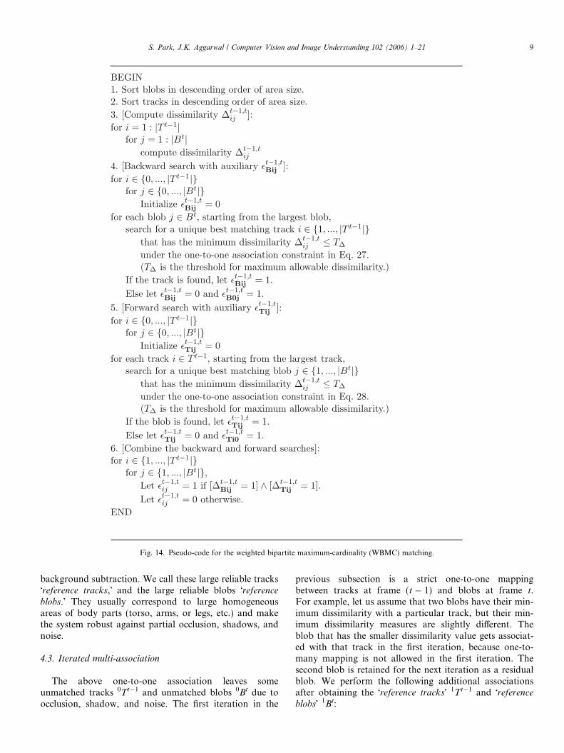
Fig. 14. Pseudo-code for the weighted bipartite maximum-cardinality (WBMC) matching.
S. Park, J.K. Aggarwal / Computer Vision and Image Understanding 102 (2006) 1–21 9
background subtraction. We call these large reliable tracks�reference tracks,� and the large reliable blobs �reference
blobs.� They usually correspond to large homogeneousareas of body parts (torso, arms, or legs, etc.) and makethe system robust against partial occlusion, shadows, andnoise.
4.3. Iterated multi-association
The above one-to-one association leaves someunmatched tracks 0Tt�1 and unmatched blobs 0Bt due toocclusion, shadow, and noise. The first iteration in the
previous subsection is a strict one-to-one mappingbetween tracks at frame (t � 1) and blobs at frame t.For example, let us assume that two blobs have their min-imum dissimilarity with a particular track, but their min-imum dissimilarity measures are slightly different. Theblob that has the smaller dissimilarity value gets associat-ed with that track in the first iteration, because one-to-many mapping is not allowed in the first iteration. Thesecond blob is retained for the next iteration as a residualblob. We perform the following additional associationsafter obtaining the �reference tracks� 1Tt�1 and �reference
blobs� 1Bt:
1 1
2 2
3 3
4 4
5 5
6 6
7
Tracks T Blobs B
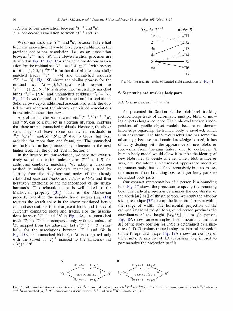
Fig. 16. Intermediate results of iterated multi-association for Fig. 11.
10 S. Park, J.K. Aggarwal / Computer Vision and Image Understanding 102 (2006) 1–21
1. A one-to-one association between 1Tt�1 and 0Bt.2. A one-to-one association between 0Tt�1 and 1Bt.
We do not associate 0Tt�1 and 0Bt, because if there hadbeen any association, it would have been established in theprevious one-to-one association, i.e., as an associationbetween 1Tt�1 and 1Bt. The above iteration processes aredepicted in Fig. 15. Fig. 15A shows the one-to-one associ-ation for the residual set 0Tt�1 = {3,4} ˝ Tt�1 with respectto 1Bt = {1,2,3,4}. 0Tt�1 is further divided into successfullymatched tracks 01Tt�1 = {4} and unmatched residuals00Tt�1 = {3}. Fig. 15B shows the similar process for theresidual set 0Bt = {5,6,7} ˝ Bt with respect to1Tt�1 = {1, 2,5,6}. 0Bt is divided into successfully matchedblobs 01Bt = {5,6} and unmatched residuals 00Bt = {7}.Fig. 16 shows the results of the iterated multi-associations.Solid arrows depict additional associations, while the dot-ted arrows represent the already established associationsin the initial association step.
Any of the matched/unmatched sets,01Tt�1, 00Tt�1, 01Bt,and 00Bt, can be a null set in a certain situation, implyingthat there are no unmatched residuals. However, the abovesteps may still leave some unmatched residuals in00Tt�1˝0Tt�1 and/or 00Bt ˝ 0Bt due to blobs that wereoccluded for more than one frame, etc. The unmatchedresiduals are further processed by inference in the nexthigher level, i.e., the object level in Section 5.
In the iterated multi-association, we need not exhaus-tively search the entire nodes spaces Tt�1 and Bt foradditional candidate matching. We adopt a relaxationmethod in which the candidate matching is tried bystarting from the neighborhood nodes of the alreadyestablished reference tracks and reference blobs and theniteratively extending to the neighborhood of the neigh-borhoods. This relaxation idea is well suited to theMarkovian property ([31]). That is, the Markovianproperty regarding the neighborhood system (Eq. (14))restricts the search space in the above mentioned iterat-ed multiassociations to the adjacent blobs and tracks ofcurrently compared blobs and tracks. For the associa-tions between 0Tt�1 and 1Bt in Fig. 15A, an unmatchedtrack 0T t�1
i 2 0T t�1 is compared only with the subset of1Bt
j mapped from the adjacency list CðT t�1i Þ � 1T t. Simi-
larly, for the associations between 1Tt�1 and 0Bt inFig. 15B, an unmatched blob Bt
j 2 0Bt is compared onlywith the subset of 1T t�1
i mapped to the adjacency listCðBt
jÞ � 1Bt.
A B
Fig. 15. Additional one-to-one associations for sets 0Tt�1 and 1Bt (A) and for00Tt�1is unmatched (A). 01Bt is one-to-one associated with 11Tt�1 whereas 00B
5. Segmenting and tracking body parts
5.1. Coarse human body model
As presented in Section 4, the blob-level trackingmethod keeps track of deformable multiple blobs of mov-ing objects along a sequence. The blob-level tracker is inde-pendent of specific object models, because no domainknowledge regarding the human body is involved, whichis an advantage. The blob-level tracker also has some dis-advantage; because no domain knowledge is used, it hasdifficulty dealing with the appearance of new blobs orrecovering from tracking failure due to occlusion. Ahuman body model would allow it to infer the identity ofnew blobs, i.e., to decide whether a new blob is face orarm, etc. We adopt a hierarchical appearance model ofthe human body that is defined recursively in a coarse-to-fine manner: from bounding box to major body parts toindividual body parts.
Our coarsest representation of a person is a boundingbox. Fig. 17 shows the procedure to specify the boundingbox. The vertical projection determines the coordinates ofthe width ½Mj
1;Mj2� of the jth person. We apply the window
slicing technique [32] to crop the foreground person withinthe range of width. The horizontal projection of thecropped image of the jth foreground person produces thecoordinates of the height ½Mj
3;Mj4� of the jth person.
Fig. 18A shows some examples. The horizontal coordinateMj
5 of the body position ðMj5;M
j6Þ is determined by a mix-
ture of 1D Gaussians trained using the vertical projectionof the foreground image. Fig. 19A shows an example ofthe results. A mixture of 1D Gaussians hGTj is used toparameterize the projection profile.
sets 1Tt�1 and 0Bt (B). 01Tt�1 is one-to-one associated with 11Bt whereastis unmatched (B).

M41
M11
M31
M21
M12
M22
M32
M71
M42
Hg1
M82 Hg
2
(M5 ,1 M )6
1 (M5 ,2 M )6
2
A B
Fig. 18. Bounding box of each person and its coordinate values (A), and the division of bounding box into three parts: head, upper body, and lower body(B).
Verticalprojection
Boundarysearching
Horizontalprojection
Boundarysearching
Low-passfiltering
Fig. 17. The procedure to specify a bounding box of a person.
S. Park, J.K. Aggarwal / Computer Vision and Image Understanding 102 (2006) 1–21 11
hGTj ¼ flGTj; rGTj; P GTjg; j 2 ½1;Np�; ð31Þ
where lGTj is the mean, rGTj is the standard deviation, andPGTj is the prior probability of the ith Gaussian, respective-ly. The body position ðMj
5;Mj6Þ of the jth person in Fig. 18
is determined from the Gaussian fitting and the 1D projec-tion as follows:
Mj5 ¼ lGTj; ð32Þ
Mj6 ¼ ðM
j3 þMj
4Þ=2. ð33ÞAs the persons translate, the Gaussian parameters are
updated along the sequence in a frame-by-frame man-ner. Updating these Gaussian parameters along thesequence amounts to tracking the whole body transla-tion of each person on the horizontal image dimension.The x-axis of the plot in Fig. 19B represents the framenumber and the y-axis represents the horizontal imagedimension. In Fig. 19B, we can see that the left person(person A) approaches to the right person (person B),who stands still up to frame 17; then person B movesback while person A remains standing still. However,we don�t know what kind of event happens betweenthe two persons. Does person A push person B, or doesperson A meet person B and person B turn back anddepart?
To recognize the specific interaction, we process the datain more detail. The next subsection presents the detailed-level tracking of individual body parts.
5.2. Division to body parts
The detailed-level tracking aims at two goals: (1) seg-mentation of body parts and (2) simultaneous tracking ofthe multiple body parts along the sequence. The segmenta-tion of body parts has two steps: (a) generation of detailedbounding box and (b) registration of blobs to the boundingbox.
The generation of the detailed bounding box is achievedby refining the the bounding box in Section 5.1. Thebounding box is divided into three parts: constructed head,upper body, and lower body. The three body parts of thebounding box are specified in terms of a region of interest(ROI), defined as follows:
• The head is defined by the vertical range from the top toMj
7ð¼ 0:16Þ times the height Hjg of the person�s fore-
ground silhouette. The height H jg is defined as
H jg ¼ ðM
j4 �Mj
3Þ. ð34Þ
• The upper body is defined by the vertical range fromMj
7ð¼ 0:16Þ times the height to Mj8ð¼ 0:45Þ times the
height of the silhouette.• The lower body is defined by the vertical range of the
rest of the silhouette.
Fig. 18B shows an example. The division of the three bodyparts is similar to our previous approach in [20]. The cur-rent system, however, is capable of self-adjusting theparameters ðMj
1; . . . ;Mj8Þ during the tracking, once the
parameters are initialized. The values of the parametersare dynamically updated according to the change of theappearance of each person in the current frame, and theupdated values are used as the initial values to estimatethe body parts in the next frame.
Each of the segmented body parts is recursively sub-di-vided into skin and non-skin parts; for example, the head isdivided into the face part and the hair part. The systemdoes not attempt the recovery of exact body structure.For example, the system does not distinguish betweentwo arms nor between two legs. The system only separateskin regions and non-skin regions of the upper body andthe lower body. Skin information is very useful for surveil-lance applications because skin color is an invariant prop-erty that indicates the presence of exposed body parts
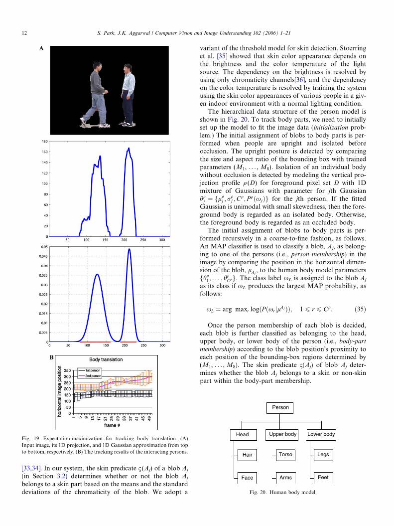
Fig. 19. Expectation-maximization for tracking body translation. (A)Input image, its 1D projection, and 1D Gaussian approximation from topto bottom, respectively. (B) The tracking results of the interacting persons.
Person
Head Upper body Lower body
LegsTorsoHair
Face Arms Feet
Fig. 20. Human body model.
12 S. Park, J.K. Aggarwal / Computer Vision and Image Understanding 102 (2006) 1–21
[33,34]. In our system, the skin predicate 1 (Aj) of a blob Aj
(in Section 3.2) determines whether or not the blob Aj
belongs to a skin part based on the means and the standarddeviations of the chromaticity of the blob. We adopt a
variant of the threshold model for skin detection. Stoerringet al. [35] showed that skin color appearance depends onthe brightness and the color temperature of the lightsource. The dependency on the brightness is resolved byusing only chromaticity channels[36], and the dependencyon the color temperature is resolved by training the systemusing the skin color appearances of various people in a giv-en indoor environment with a normal lighting condition.
The hierarchical data structure of the person model isshown in Fig. 20. To track body parts, we need to initiallyset up the model to fit the image data (initialization prob-lem.) The initial assignment of blobs to body parts is per-formed when people are upright and isolated beforeocclusion. The upright posture is detected by comparingthe size and aspect ratio of the bounding box with trainedparameters (M1, . . . , M8). Isolation of an individual bodywithout occlusion is detected by modeling the vertical pro-jection profile q (D) for foreground pixel set D with 1Dmixture of Gaussians with parameter for jth Gaussianhq
j ¼ flqj ; r
qj ;C
q; P qðxjÞg for the jth person. If the fittedGaussian is unimodal with small skewedness, then the fore-ground body is regarded as an isolated body. Otherwise,the foreground body is regarded as an occluded body.
The initial assignment of blobs to body parts is per-formed recursively in a coarse-to-fine fashion, as follows.An MAP classifier is used to classify a blob, Aj, as belong-ing to one of the persons (i.e., person membership) in theimage by comparing the position in the horizontal dimen-sion of the blob, lAj
, to the human body model parametersfhq
1 ; . . . ; hqCqg. The class label xL is assigned to the blob Aj
as its class if xL produces the largest MAP probability, asfollows:
xL ¼ arg maxr logðP ðxrjlAjÞÞ; 1 6 r 6 Cq. ð35Þ
Once the person membership of each blob is decided,each blob is further classified as belonging to the head,upper body, or lower body of the person (i.e., body-part
membership) according to the blob position�s proximity toeach position of the bounding-box regions determined by(M1, . . . , M8). The skin predicate 1(Aj) of blob Aj deter-mines whether the blob Aj belongs to a skin or non-skinpart within the body-part membership.

S. Park, J.K. Aggarwal / Computer Vision and Image Understanding 102 (2006) 1–21 13
Each slot in Fig. 20 corresponding to an individualbody part contains a list of tracked blobs that correspondto that part. Some slots can be empty. For example, theface part may be empty if the face is hidden from thecamera view. In contrast, body parts can share a commonblob label if one body part occludes another. Person iden-tity Pi is maintained by monitoring the overall blob listsin a human body model. In this framework, segmentingand tracking body parts amounts to properly updatingthe associated blob list of each slot across the imagesequence. Skin and non-skin regions of the upper- andlower-body are also separated. The goal is to preciselysegment and track homogeneous regions that may corre-spond to human body parts mostly based on appearancewith little help from body kinematics information. Mini-mizing the use of body kinematics gives our algorithmmore flexibility for model-free tracking. We think thatfurther separation of torso, arms, and legs amounts to apose estimation problem, for which we presented a solu-tion in [37].
5.3. Body part tracking
The initially assigned blobs are then tracked along thesequence by the tracking mechanism described in Section 4.
Fig. 21 shows a diagram of the inter-weaved mechanismbetween the blob-level and the object-level tracking. Theoverall process is a twofold tracking scheme that consistsof blob-to-blob matching in consecutive frames and blob-to-body part association within a frame. We explain theprocess at time frame t2 as an example.
At every time frame ti (i = 1, 2, 3 in Fig. 21), blobs at ti
are obtained by the relaxation process in Section 3. Theblob-to-blob matching is depicted by the tracking arrowsin Fig. 21. (See the tracking arrow from t2 to t3.) The blobsare matched to the blobs at next frame by the multi-blobtracking process in Section 4.
The tracked blobs are grouped to form the body parts atthe current frame. (See the horizontal grouping arrows attime t2.) The grouping process is controlled by the bodyposture at the previous frame. (See the updating arrowfrom t1 to t2.)
Fig. 21. Interweaved tracking framework.
The blob tracking process at the current frame is assist-ed by the body posture in the previous frame. The residualblobs that are left unmatched after the iterated multi-asso-ciation stage are handled by inference that refers to thebody posture history of the previous frame; they are includ-ed in the most probable body parts according to the bodyposture history. (See the referencing arrow from t1 to t2.)
After the initialization of body parts, body parts at ti areupdated from the previous frame at every time frame ti.Updating the body parts implies the update of the memberblob labels based on the grouped blobs.
Blob tracking at time t2 is guided by blob trackingresults at time t1 and body part configuration at time t1.Body part tracking at time t2 is guided by the blob trackingresult at time t2 and the previous body configuration attime t1. This mechanism is an integration of bottom-up(i.e., blob-to-object) and top-down (i.e., object-to-blob)processes. The updated blob lists are registered in theappropriate slots of the human body model in Fig. 20.Our algorithm uses motion information when the transla-tion of a whole body is tracked at the object level. Theobject level tracking uses the expectation–maximization(EM) algorithm to update the position of the body usinga mixture of 1D Gaussians to represent the vertical projec-tion of the body.
6. Experimental results
6.1. A prototype system
The prototype system was coded in MatLab from Math-works Inc. and run on a personal computer installed withthe Microsoft Windows 2000 operating system. The com-puter was equipped with two Pentium-IV processors fromIntel Corporation with 850 MHz clock speed. A SonyVX-2000 digital video camera was used to acquire the vid-eo data. The video camera was positioned on a tripod andoriented with its viewing direction parallel to the floor. Wecaptured two-person interaction videos in indoor environ-ments with a cluttered background. The video data wereconverted into image sequences of Windows AVI files, in15 frame/s sequences of 320x240 pixel color images. Thecolor quality was 24 bit (i.e., 8 bits for each of the red,green, and blue color channels.)
We have tested our system for various two-person inter-actions including (1) approaching each other, (2) departingeach other, (3) pointing, (4) shaking hands, (5) hugging, (6)standing hand-in-hand, (7) punching, (8) pushing, and (9)kicking.
Six different pairs of interacting persons were used toobtain the total 54 sequences (i.e., 9 interactions · 6 pairsof people). A total of 285, 293, 232, 372, 268, 281, 220,230, and 264 frames were contained in each of the aboveinteraction types (1)–(9), respectively. The gross total num-ber of the frames was 2445 frames. The subjects wore var-ious casual clothes, and were instructed to interact eachother in a natural manner for the nine interaction types.
14 S. Park, J.K. Aggarwal / Computer Vision and Image Understanding 102 (2006) 1–21
An interaction sequence contains a single instance of aninteraction between two persons, and varies in durationin the range of 2.5–4.1 s depending on the persons.
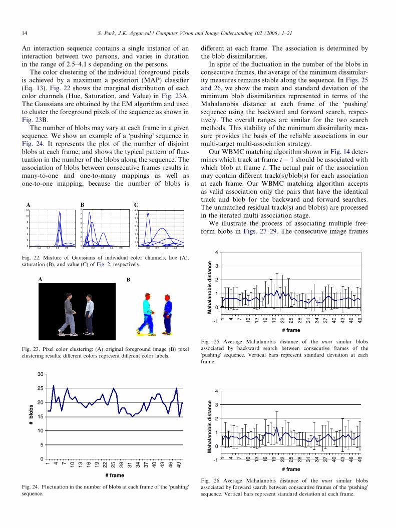
The color clustering of the individual foreground pixelsis achieved by a maximum a posteriori (MAP) classifier(Eq. 13). Fig. 22 shows the marginal distribution of eachcolor channels (Hue, Saturation, and Value) in Fig. 23A.The Gaussians are obtained by the EM algorithm and usedto cluster the foreground pixels of the sequence as shown inFig. 23B.
The number of blobs may vary at each frame in a givensequence. We show an example of a �pushing� sequence inFig. 24. It represents the plot of the number of disjointblobs at each frame, and shows the typical pattern of fluc-tuation in the number of the blobs along the sequence. Theassociation of blobs between consecutive frames results inmany-to-one and one-to-many mappings as well asone-to-one mapping, because the number of blobs is
0 0.2 0.4 0.6 0.8 10
2
4
6
8
10
12
0 0.2 0.4 0.6 0.8 10
1
2
3
4
5
6
7
8
0 0.2 0.4 0.6 0.8 10
0.5
1
1.5
2
2.5
3
3.5
4
4.5
A B C
Fig. 22. Mixture of Gaussians of individual color channels, hue (A),saturation (B), and value (C) of Fig. 2, respectively.
Fig. 23. Pixel color clustering: (A) original foreground image (B) pixelclustering results; different colors represent different color labels.
30
25
20
15
# b
lob
s
10
5
0
# frame
1 4 7 10 13 16 19 22 25 28 31 34 37 40 43 46 49
Fig. 24. Fluctuation in the number of blobs at each frame of the �pushing�sequence.
different at each frame. The association is determined bythe blob dissimilarities.
In spite of the fluctuation in the number of the blobs inconsecutive frames, the average of the minimum dissimilar-ity measures remains stable along the sequence. In Figs. 25and 26, we show the mean and standard deviation of theminimum blob dissimilarities represented in terms of theMahalanobis distance at each frame of the �pushing�sequence using the backward and forward search, respec-tively. The overall ranges are similar for the two searchmethods. This stability of the minimum dissimilarity mea-sure provides the basis of the reliable associations in ourmulti-target multi-association strategy.
Our WBMC matching algorithm shown in Fig. 14 deter-mines which track at frame t � 1 should be associated withwhich blob at frame t. The actual pair of the associationmay contain different track(s)/blob(s) for each associationat each frame. Our WBMC matching algorithm acceptsas valid association only the pairs that have the identicaltrack and blob for the backward and forward searches.The unmatched residual track(s) and blob(s) are processedin the iterated multi-association stage.
We illustrate the process of associating multiple free-form blobs in Figs. 27–29. The consecutive image frames
-1
Mah
alan
ob
is d
ista
nce
1
0
2
3
4
# frame
41 7 10 13 16 19 22 25 28 31 34 37 40 43 46 49
Fig. 25. Average Mahalanobis distance of the most similar blobsassociated by backward search between consecutive frames of the�pushing� sequence. Vertical bars represent standard deviation at eachframe.
-1
Mah
alan
ob
is d
ista
nce
1
0
2
3
4
# frame
41 7 10 13 16 19 22 25 28 31 34 37 40 43 46 49
Fig. 26. Average Mahalanobis distance of the most similar blobsassociated by forward search between consecutive frames of the �pushing�sequence. Vertical bars represent standard deviation at each frame.

Fig. 28. The minimum blob-dissimilarity measures chosen from every pair of tracks and blobs between consecutive frames in Fig. 27: (A) between Frames38 and 39, (B) between frames 39 and 40 (�999 represents unmatched outlier after the one-to-one association stage).
Fig. 27. The consecutive image frames (A) 38, (B) 39, and (C) 40, with blob labels L (Aj) embedded in each blob at each frame. Note that the number andshape of the blobs change at each frame.
Fig. 29. The established track labels after the one-to-one association.Large-font numbers represent one-to-one association results, and small-font numbers represent residues which are to be associated in the nextiterative many-to-many association step. Updated blob labels at frame 39according to blob labels at frame 38 as track set (A), and updated bloblabels at frame 40 according to blob labels at frame 39 as track set (B).
S. Park, J.K. Aggarwal / Computer Vision and Image Understanding 102 (2006) 1–21 15
with blob labels L (Aj) embedded in each blob are shown inFig. 27A–C. The numbers at the upper left corner at eachframe stand for the actual frame indices of the sequence.Note that the blob labels vary arbitrarily in consecutiveframes.
We compute the blob dissimilarities for every pair oftracks at frame t � 1 and blobs at frame t in terms ofMahalanobis distance in Eq. (19), and choose the mini-mum value for each blob at frame t. The minimum dis-similarity measures between Fig. 27A and B are shownin Fig. 28A, and the minimum dissimilarity measuresbetween Fig. 27B and C are shown in Fig. 28B. The valueof �999 represents a mismatched outlier measure at the
one-to-one association stage. The results of the initialone-to-one association of each blob at the current framewith respect to each track at the previous frame areshown in Fig. 29. The numbers in large font in Fig. 29represent the associated track labels of the previous frameto update the current frame. For example, Label 10 atFrame 39 in Fig. 29A corresponds to Label 8 at Frame39 in Fig. 27B, which was updated to Label 10 at Frame38 (in Fig. 27A) with the minimum dissimilarity measureof 0.67949 at Frame 39 (shown at the left person�s headin Fig. 28A).
Overall, the established track labels shown in largefont in Fig. 29A represent the labels updated from theoriginal blob labels in Fig. 27B to the track labels inFig. 27A for tracking. In a similar manner, the estab-lished track labels in large font in Fig. 29B representthe labels updated from the original blob labels inFig. 27C to the track labels in Fig. 27B for tracking.The outlier labels in small font in Fig. 29A and B areunmatched residuals which are assigned temporary tracklabels and reserved for the extra association step in theiterated multi-association process.
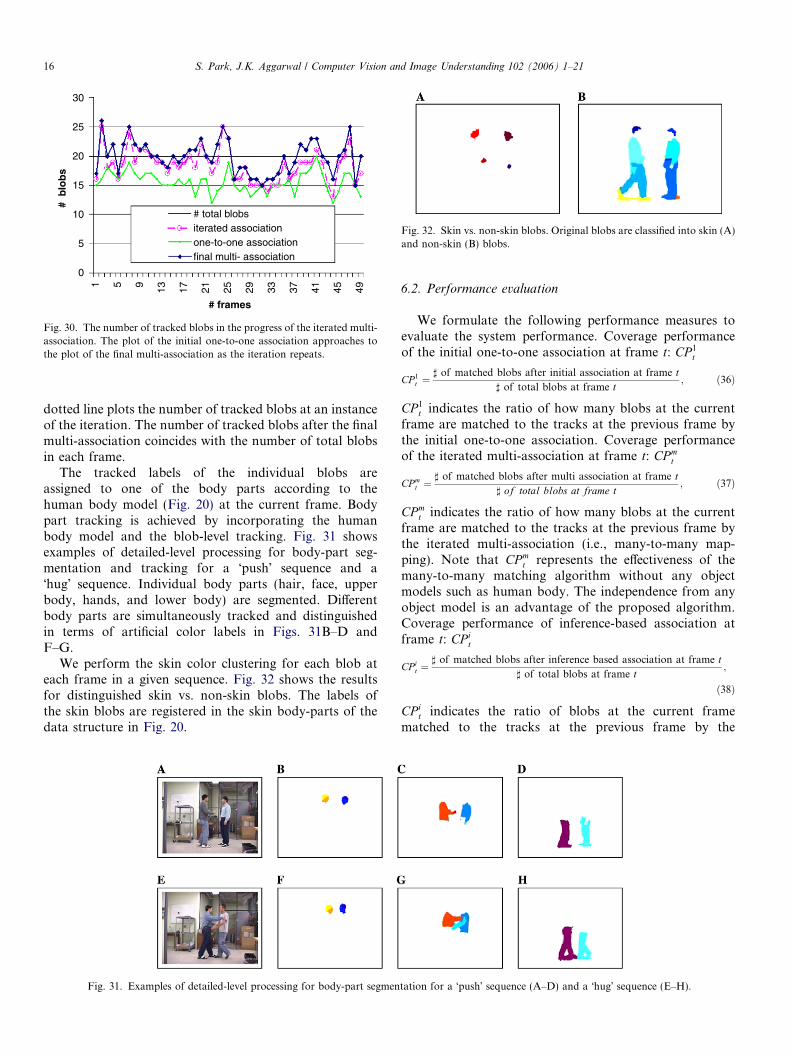
The progress of the iterated multi-association is shownin Fig. 30. The number of correctly tracked blobs afterthe initial one-to-one association stage is less than the num-ber of total blobs in Fig. 24. The unmatched residual blobsare processed by the iterated multi-association step,increasing the number of correctly tracked blobs. The plotof the initial one-to-one association approaches the plot ofthe final multi-association as the iteration repeats. The
30
25
20
15
# b
lob
s
10
5
0
# frames
# total blobsiterated associationone-to-one associationfinal multi- association
1 5 9 13 17 21 25 29 33 37 41 45 49
Fig. 30. The number of tracked blobs in the progress of the iterated multi-association. The plot of the initial one-to-one association approaches tothe plot of the final multi-association as the iteration repeats.
Fig. 32. Skin vs. non-skin blobs. Original blobs are classified into skin (A)and non-skin (B) blobs.
16 S. Park, J.K. Aggarwal / Computer Vision and Image Understanding 102 (2006) 1–21
dotted line plots the number of tracked blobs at an instanceof the iteration. The number of tracked blobs after the finalmulti-association coincides with the number of total blobsin each frame.
The tracked labels of the individual blobs areassigned to one of the body parts according to thehuman body model (Fig. 20) at the current frame. Bodypart tracking is achieved by incorporating the humanbody model and the blob-level tracking. Fig. 31 showsexamples of detailed-level processing for body-part seg-mentation and tracking for a �push� sequence and a�hug� sequence. Individual body parts (hair, face, upperbody, hands, and lower body) are segmented. Differentbody parts are simultaneously tracked and distinguishedin terms of artificial color labels in Figs. 31B–D andF–G.
We perform the skin color clustering for each blob ateach frame in a given sequence. Fig. 32 shows the resultsfor distinguished skin vs. non-skin blobs. The labels ofthe skin blobs are registered in the skin body-parts of thedata structure in Fig. 20.
Fig. 31. Examples of detailed-level processing for body-part segmen
6.2. Performance evaluation
We formulate the following performance measures toevaluate the system performance. Coverage performanceof the initial one-to-one association at frame t: CP 1
t
CP 1t ¼
] of matched blobs after initial association at frame t] of total blobs at frame t
; ð36Þ
CP 1t indicates the ratio of how many blobs at the current
frame are matched to the tracks at the previous frame bythe initial one-to-one association. Coverage performanceof the iterated multi-association at frame t: CP m
t
CP mt ¼
] of matched blobs after multi association at frame t] of total blobs at frame t
; ð37Þ
CP mt indicates the ratio of how many blobs at the current
frame are matched to the tracks at the previous frame bythe iterated multi-association (i.e., many-to-many map-ping). Note that CP m
t represents the effectiveness of themany-to-many matching algorithm without any objectmodels such as human body. The independence from anyobject model is an advantage of the proposed algorithm.Coverage performance of inference-based association atframe t: CP i
t
CP it ¼
] of matched blobs after inference based association at frame t] of total blobs at frame t
;
ð38Þ
CP it indicates the ratio of blobs at the current frame
matched to the tracks at the previous frame by the
tation for a �push� sequence (A–D) and a �hug� sequence (E–H).

S. Park, J.K. Aggarwal / Computer Vision and Image Understanding 102 (2006) 1–21 17
inference-based association using a human body model.CP i
t is domain-specific because an explicit human bodymodel is involved. The averages of the coverage-perfor-mance measures for CP 1
t , CP mt , and CP i
t, respectively, aredefined as follows:
CP 1 ¼ ð1=F ÞXF
t¼1
CP 1t ; ð39Þ
CP m ¼ ð1=F ÞXF
t¼1
CP mt ; ð40Þ
CP i ¼ ð1=F ÞXF
t¼1
CP it; ð41Þ
where F = gross total number of frames = 2445 frames.The performance measures in Eqs. (39)–(41) evaluate the
Table 1Performance evaluation of the system
CP1 CPm PPi
Average 0.792 0.928 0.973Std. dev. 0.097 0.054 0.056
Fig. 33. Segmentation and tracking of interacting human body parts. Raw se�pushing� (C).
system performance in terms of blobs. We introduce anoth-er performance measure to evaluate the system perfor-mance in terms of pixels. Precision performance of bodyparts tracking: PP i
t
PP it ¼ 1� ] of pixels in mismatched blobs of all the body parts
] of pixels in all foreground areas at frame t; ð42Þ
PP it represents the ratio of pixels correctly assigned to the
corresponding individual body parts at frame t. The preci-sion performance indicates how well the body parts aresegmented and tracked at the object level at each frame.Average precision performance of inference-assisted map-ping: PPi
PP i ¼ ð1=F ÞXF
t¼1
PP it; ð43Þ
where F = gross total number of frames = 2445 frames.The coverage-performance criteria, CP1, CPm, and CPi
represent the percentages of correctly associated blobs ateach stage of the blob-tracking algorithm in terms of blobnumbers. The precision-performance criterion PPi repre-sents the final precision of the segmented and tracked bodyparts in terms of the number of pixels in the body parts. We
quence and tracking sequence of �punching� (A), �hand-shaking� (B), and
18 S. Park, J.K. Aggarwal / Computer Vision and Image Understanding 102 (2006) 1–21
have developed a semi-automatic user interface program toefficiently count the number of matched and mismatchedblobs and the number of pixels in each of the blobs perframe to compute CP 1
t , CP mt , CP i
t, and PP it.
The summary results of performance evaluations of thesystem, CP1, CPm, CPi, and PPi, are shown in Table 1. CP1
shows that 79% of the total blobs are correctly associatedat the initial one-to-one matching process, and CPm showsthat 93% of the total blobs are associated by the iterativemany-to-many matching process. CPi indicates that all
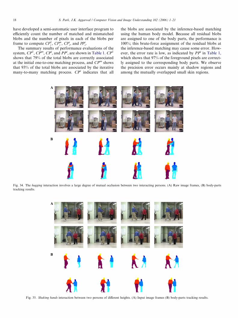
Fig. 34. The hugging interaction involves a large degree of mutual occlusiontracking results.
Fig. 35. Shaking hands interaction between two persons of different
the blobs are associated by the inference-based matchingusing the human body model. Because all residual blobsare assigned to one of the body parts, the performance is100%; this brute-force assignment of the residual blobs atthe inference-based matching may cause some error. How-ever, the error rate is low, as indicated by PPi in Table 1,which shows that 97% of the foreground pixels are correct-ly assigned to the corresponding body parts. We observethe precision error occurs mainly at shadow regions andamong the mutually overlapped small skin regions.
between two interacting persons. (A) Raw image frames, (B) body-parts
heights. (A) Input image frames (B) body-parts tracking results.
S. Park, J.K. Aggarwal / Computer Vision and Image Understanding 102 (2006) 1–21 19
6.3. Example sequences
We show some example sequences of �punching,� �hand-shaking,� and �pushing� behavior in Fig. 33. These imagesequences were obtained using different persons. The firstrow of each sequence shows the subsampled frames ofthe color input video, and the second row represents thecorresponding frames of the output from the system. Theinteracting persons� individual body parts are correctly seg-mented and tracked across the sequences. The degree ofocclusion and shadow in these interactions is small.
The �hugging� sequence shown in Fig. 34 involves a largedegree of occlusion and shadow. Processing this sequenceis challenging, because the upper bodies of the interactingpersons occlude each other and cause bisection of the indi-vidual torso. Note that the left person�s head is completelyoccluded during the interaction. The bisected and occludedbody parts are successfully recovered after the personsdepart. Previous algorithms such as [13] did not addressthe tracking problems in human interactions. Our systemcorrectly handles partial occlusion and shadows caused byinteracting body parts, and reliably tracks the body partsat the object level. Note also that the persons in the sequencechange from lateral view to frontal view. Our system tracksthe persons successfully along the change of view.
Most of the body parts are correctly segmented and reli-ably tracked over time, except that closely adjacent groupsof small skin blobs are sometimes confused. Confusion alsooccurs when a blob is completely occluded by another blobas shown in the two heads of the sequence. However thisconfusion is corrected automatically and the occludedbody part is recovered once the blobs move apart.
We show an example sequence of the �hand-shaking�interaction between two persons of different heights inFig. 35. The sequence involves a deviation of 30� inclina-tion with the imaging plane of the camera. The sequencealso involves a progressive change of human body size asthe persons move. The system performs correctly with thesequence.
7. Conclusions
In this paper we presented a method for tracking bodyparts of interacting persons by combining the attributerelational graph (ARG) and multi-target multi-associationtracking (MMT) for data association among multiple free-form blobs in a color video. The proposed method (i.e.,ARG–MMT) may be used to segment and track multiplebody parts of interacting persons in the presence of occlu-sion and shadow.
Our method applies a hierarchical framework. At pixellevel, a Gaussian mixture model is used to classify pixelsinto coherent blobs. At blob level, ARG is applied to formhomogeneous blobs and data association is used to trackthe blobs. At object level, a coarse human body model isused as domain knowledge to resolve ambiguity due toocclusion and image noise.
The contributions of this paper are as follows: (i) anintegration of ARG and multitarget-multiassociationtracking is proposed to track multiple objects. (ii) A newframework for simultaneous segmentation and trackingof entire human body parts is presented. (iii) A propertreatment of mutual occlusion and shadowing is achievedby the many-to-many mapping at the blob level and bythe ambiguity resolution by inference at the object level.
We demonstrated the system performance for simulta-neous segmentation and tracking of multiple human bodyparts for various interactions, including �approaching,� �de-parting,� �pointing,� �hand-shaking,� �standing hand-in-hand,� �punching,� �kicking,� and �pushing.�
The system is robust to height variation of the personsand to the progressive change of the heights as the personsmove along the camera viewing direction. The system canalso tolerate various views of the body (i.e., front view, sideview, and rear view of the persons).
The system has certain limitations due to the use ofappearance-based method with minimal domain knowl-edge about human body. If a person wears a garment ofhomogeneous color such as a black suit or a white dress,then the system may not distinguish the person�s upperbody and lower body. If two persons wear clothes of sim-ilar color, the system may confuse the two persons whenthe persons overlap each other. In such cases, the systemonly relies on the human body model for the initializationof body parts, and the body-part ratios between head,upper body and lower body are not updated from the ini-tialized values along the sequence. Incorporating a moreelaborate body model will reduce the confusion. We planto address this in future work.
The speed of the prototype system is not real-time, butthe system can process successive frames serially on thefly and track body parts on-line without user involvementduring the operation. Optimized implementation using Cwould increase the speed substantially, which would beour future plan. This system can be used as a segmentationand tracking unit for a high-level recognition system forhuman interactions that occasionally involves severe occlu-sion between articulated body parts. The system will beused as the tracking module of a recognition system for rec-ognizing complex human motion patterns such as mutualinteraction.
Appendix A. Nomenclature
Table A.1 summarizes the symbols used in this paper.
Appendix B. Merging similar Gaussians
1. The process of merging similar Gaussians uses the fol-lowing greedy algorithm:
• Sort all Gaussians in descending order.• Pick first Gaussian and find Gaussians which are close
to its means.

Table A.1Summary of symbols used in the paper
Symbol Meaning Range Value
v (x,y) Vector of pixel intensity at (x,y) [0,255] —Xk Vector of pixel intensity of the kth pixeldX (x,y) Gaussian background model of pixel (x,y) — —dU Mahalanobis distance of color feature U — —F (x,y) Foreground mask at (x,y) before thresholding — —g Number of frames used for training Gaussians — 5xi ith class label in pixel-color clusteringli Mean intensity of pixels in the ith classRi Covariance of pixel intensity in the ith classL (q) Blob label of blob q — —C (q) Adjacency list of blob q — —W (q) Set of border pixels in blob q — —s (q,�) Tertiary relations between blobs q and � {0,1} —f Maximum iterations in the Gaussian training — 20a (q) Blob size of blob q — —b Border-ratio — —1 (q) Skin predicate of blob q {0,1}Bt
j jth blob at time (t)T t�1
i ith track at time (t � 1)mt
j jth blob�s feature vector for similarity at time t
Dt�1;tij Mahalanobis distance for blob tracking
Pt Covariance matrix of blob features at time t
�t�1;tij Edge in bipartite graph between T t�1
i and Btj {0,1}
Nq Edge set of maximum association in bipartite graphK Overall dissimilarity in one-to-one association
Bracket [ ] and curly bracket {} represent continuous real domain and discrete integer domain, respectively.
20 S. Park, J.K. Aggarwal / Computer Vision and Image Understanding 102 (2006) 1–21
• Cluster these similar Gaussians into one Gaussian.• Remove merged Gaussians from list.• Repeat for next Gaussian in list.
2. For example, if m color Gaussians are being mergedinto one:
• New weight is the sum of m weights.• New mean is the mean of m means.• New covariance is computed as follows:
– Compute eigenvalues k1� � �k3m of covariance matrices.– Compute eigenvectors v1� � �v3m of covariance matrices– Let V = [k1v1� � �k3mv3m].– Apply PCA to V for optimal eigenvectors I1, I2 and I3.– Project k1v1� � �k3mv3m on I1, I2 and I3 and let the max-
imum projection be the new eigenvalues D.– Reconstruct new covariance as E * D * E 0, E = [I1,
I2,I3].
References
[1] J.K. Aggarwal, Q. Cai, Human motion analysis: a review, Comput.Vision Image Understand. 73 (3) (1999) 295–304.
[2] D. Gavrila, The visual analysis of human movement: a survey,Comput. Vision Image Understand. 73 (1) (1999) 82–98.
[3] T. Moeslund, E. Granum, A survey of computer vision-based humanmotion capture, Comput. Vision Image Understand. 81 (3) (2001)231–268.
[4] J. Webb, J.K. Aggarwal, Structure from motion of rigid and jointedobjects, Artif. Intell. 19 (1982) 107–130.
[5] S.X. Ju, M.J. Black, Y. Yacoob, Cardboard people: A parameter-ized model of articulated motion, in: Internat. Conf. on AutomaticFace and Gesture Recognition, Killington, Vermont, 1996, pp. 38–44.
[6] D. Hogg, Model-based vision: a program to see a walking person,Image Vision Comput. 1 (1) (1983) 5–20.
[7] D. Gavrila, L. Davis, 3-d model-based tracking of humans in action:a multi-view approach, in: Computer Vision and Pattern Recognition,1996. Proceedings, 1996, pp. 73–80.
[8] I.A. Kakadiaris, 3d human body model acquisition from multipleviews, Int. J. Comput. Vision 30 (3) (1998) 191–218.
[9] C. Barron, I.A. Kakadiaris, Estimating anthropometry and pose froma single uncalibrated image, Comput. Vision Image Understand. 81(2001) 269–284.
[10] M. Kass, A. Witkin, D. Terzopoulos, Snakes: active contour models,Int. J. Comput. Vision (1988) 321–332.
[11] M. Isard, A. Blake, Condensation—conditional density propaga-tion for visual tracking, Int. J. Comput. Vision 29 (1) (1998)5–28.
[12] C. Wren, A. Azarbayejani, T. Darrell, A. Pentland, Pfinder:real-time tracking of the human body, in: Proc. Second Internat.Conf. on Automatic Face and Gesture Recognition, 1996, pp.51–56.
[13] A. Bakowski, G. Jones, Video surveillance tracking using color regionadjacency graphs, in: Image Processing and Its Applications, 1999,pp. 794–798.
[14] I. Haritaoglu, D. Harwood, L.S. Davis, W4:Real-time surveillance ofpeople and their activities, IEEE Trans. Pattern Anal. Mach. Intell.22 (8) (2000) 797–808.
[15] J. Park, S. Park, J.K. Aggarwal, Human motion tracking bycombining view-based and model-based methods for monocularvideo sequences, in: International Workshop on Computer Graphicsand Geometric Modeling, Montreal, Canada, 2003.
[16] C. Barron, I. Kakadiaris, A convex penalty method for optical humanmotion tracking, in: ACM International Workshop on VideoSurveillance (IWVS), Berkeley, CA, 2003, pp. 1–10.
S. Park, J.K. Aggarwal / Computer Vision and Image Understanding 102 (2006) 1–21 21
[17] R. Rosales, S. Sclaroff, Inferring body pose without tracking bodyparts, in: Computer Vision and Pattern Recognition, Hilton HeadIsland, South Carolina, 2000, pp. 721–727.
[18] J. Sherrah, S. Gong, Resolving visual uncertainty and occlusionthrough probabilistic reasoning, in: British Machine Vision Confer-ence, Bristol, UK, 2000, pp. 252–261.
[19] K. Sato, J.K. Aggarwal, Recognizing two-person interactions inoutdoor image sequences, in: IEEE Workshop on Multi-ObjectTracking, Vancouver, CA, 2001.
[20] S. Park, J.K. Aggarwal, Recognition of human interaction usingmultiple features in grayscale images, in: Internat. Conf. on PatternRecognition, Vol. 1, Barcelona, Spain, 2000, pp. 51–54.
[21] N. Siebel, S. Maybank, Real-time tracking of pedestrians andvehicles, in: IEEE Workshop on PETS, Kauai, Hawaii, 2001.
[22] Y.T.L.B.S.P.A. Senior, A. Hampapur, R. Bolle, Appearance modelsfor occlusion handling, in: IEEE Workshop on PETS, Kauai, Hawaii,2001.
[23] A.-R. Mansouri, A. Mitiche, Spatial/joint space-time motion seg-mentation of image sequences by level set pursuit, in: Internat. Conf.on Image Processing, 2002.
[24] Y. Bar-Shalom, W. Blair, Multitarget-multisensor tracking: applica-tions and advances, Vol. 3, Norwood, MA, 2000, pp. 199–231.
[25] K. Sato, J.K. Aggarwal, Temporal spatio-velocity transform and itsapplication to tracking and interaction, Comput. Vision ImageUnderstand. 96 (2) (2004) 100–128.
[26] R. Duda, P. Hart, E. Stork, Pattern Classification, second ed., Wiley,New York, 2001, Chapter 10, pp. 517–583.
[27] S. Khan, M. Shah, Tracking people in presence of occlusion, in: AsianConference on Computer Vision, Taipei, Taiwan, 2000.
[28] L. Salgado, N. Garcia, J. Menedez, E. Rendon, Efficient imagesegmentation for region-based motion estimation and compensa-tion, IEEE Trans. Circuits Syst. Video Technol. 10 (7) (2000)1029–1039.
[29] R. Ahuja, T. Magnanti, J. Orlin, Network Flows: Theory, Algo-rithms, and Applications, Prentice-Hall, Englewood Cliffs, NJ, 1993,pp. 462–500.
[30] J. Setubal, Sequential and parallel experimental results with bipartitematching algorithms, Technical report ic-96-09, Institute of Comput-ing, State University of Campinas, Brazil, 1996.
[31] S. Li, Markov random field modeling in image analysis, Springer-Verlag, Tokyo, 2001, pp. 81–118.
[32] A.K. Jain, Fundamentals of Digital Image Processing, Prentice-Hall,Englewood Cliffs, NJ, 1989.
[33] E. Saber, A. Tekalp, R. Eschbach, K. Knox, Automatic imageannotation using adaptive color classification, Graph. Models ImageProcess. 58 (2) (1996) 115–126.
[34] S. McKenna, Y. Raja, S. Gong, Object tracking using adaptive colormixture models, in: Asian Conference on Computer Vision, No. 1,Hong Kong, China, 1998, pp. 615–622.
[35] M. Stoerring, H. Andersen, E. Granum, Skin colour detection underchanging lighting conditions, in: 7th Symposium on IntelligentRobotics Systems, Coimbra, Portugal, 1999.
[36] J. Yang, W. Lu, A. Waibel, Skin-color modeling and adaptation, in:Asian Conference on Computer Vision, No. 2, Hong Kong, China,1998, pp. 687–694.
[37] S. Park, J.K. Aggarwal, A hierarchical bayesian network for eventrecognition of human actions and interactions, ACM MultimediaSystemsJournal,Special IssueonVideoSurveillance,2004,pp.164–179.

