Embed Size (px)
Citation preview

XXXV SIMPOSIO BRASILEIRO DE TELECOMUNICACOES E PROCESSAMENTO DE SINAIS - SBrT2017, 3-6 DE SETEMBRO DE 2017, SAO PEDRO, SP
Simultaneous Detection and Parallel InterferenceCancellation in GFDM for 5G
Juan Pablo Mayoral Arteaga, Rodrigo Pereira David and Raimundo Sampaio Neto
Abstract— The generalized frequency division multiplexingtransmission technique (GFDM), is being discussed as a candidatewaveform for the fifth generation wireless communication system(5G). Since it only uses one cyclic prefix (CP) per group ofsymbols instead of one CP per symbol, the GFDM techniqueis more spectrally efficient than the traditional OFDM systems.In this work we propose a low complexity detection schemefor GFDM where a matched filter (MF) detection is used inconjunction with the parallel interference cancellation technique(PIC). In addition to reducing the complexity of the receiver, theproposed scheme incorporates a strategy to dynamically limitthe number of iterations of the PIC. Performance results arepresented in terms of information symbol error rate (SER).
Keywords— GFDM vs OFDM, signal generation, MatchedFilter detection, Parallel Interference Cancellation technique,performance, 5G.
I. INTRODUCTION
Mobile communications networks are experiencing a sub-stantial increase in data traffic due to the several emergingapplications, such as Machine-to-Machine communications(M2M), Internet of Things (IoT), Tactile Internet [1], [2] aswell as novel broadband services like ultra High-Definition-Video-Streaming and augmented reality applications [3], [4].It is expected that this huge data exchange will continue toincrease in the next few decades leading representatives ofindustry and academia to look into the technological develop-ments towards the next generation of mobile communications(5G) [4].
There is widespread agreement that 5G systems will haveto rely on technologies that can offer a substantial increasein transmission capacity [5], through a combination of inno-vative techniques involving different network layers, withoutsignificant increase in bandwidth, and energy consumption [4].
In the physical layer, OFDM transmission system is cur-rently a solution widely used in the 4G-LTE (Long TermEvolution) system, mainly due to its robustness against multi-path channels and their relative simplicity of implementationbased on the Fast Fourier transform (FFT) algorithm [1].However, the OFDM transmission has some disadvantagessuch as limited spectral efficiency as a result of the need fora Cyclic Prefix band-guard (CP), intrinsic elevated side lobesthat increase the Out-of-Band emission level (OOB), as wellas the need for a high level of synchronization in order tomaintain the orthogonality between OFDM subcarriers [5].These factors are especially sensitives in some applicationscenarios predicted for the 5G such for instance the lowpower consumption demands in M2M communications turnsunaffordable the strict synchronization required to keep the
orthogonality between the OFDM subcarriers. In others appli-cations such as Tactile Internet and vehicular communications(V2V) which require short bursts of data, the OFDM systemswith one CP per symbol have low spectral efficiency.
Therefore, some alternative non-orthogonal multi-carrierwaveforms possessing larger spectral efficiency and lowersynchronizations requirements are being considered for 5Gsystem [5], [6].
Among these waveforms, one that is receiving increasingattention in the literature is the GFDM. One of the mainadvantages of GFDM is its larger spectral efficiency comparingto that of the CP-OFDM because it uses only one CP pertransmitted group of symbols instead of a CP per transmittedsymbol as in the CP-OFDM. In the GFDM different filterimpulse responses can be used to filter the subcarriers and thusreducing level of the OOB emissions. In addition, GFDM hasrobustness for synchronization errors [1].
In spite of aforementioned advantages, the GFDM systemexhibits intrinsic interference between its subcarriers unlikeCP-OFDM systems which has orthogonal subcarriers. Forthis reason, the development of interference cancellation tech-niques is critical. Specifically, the non-orthogonality betweenthe waveforms used in GFDM makes imperative the develop-ment of detection algorithms with jointly suppression of intercarrier interference (ICI).
Detection schemes that employ Serial Interference Cancel-lation (SIC) strategies were proposed in [7], [8] in order toeliminate ICI in GFDM transmission systems. In these worksa Zero Forcing (ZF) channel equalization is employed previ-ously to the detection scheme, which requires the inversionof the channel matrix. This increases the complexity of thereceiver especially for large receiving block of symbols.
The proposed detection scheme of this work employsMatched Filter (MF) equalization, which does not require theinversion of the channel matrix, in conjunction with the PICtechnique. In addition, to reduce the number of operationsrequired for detection, a strategy is developed to dynamicallyset the number of PIC iterations in each detection.
The remaining sections of this document are organized asfollows: Section II, introduces a matrix model representing thesignal vectors transmitted in the GFDM system. As in the caseof OFDM systems, the model is adequate and convenient forexamining possible detection techniques. Section III, presentsthe proposed detection scheme to be used in GFDM systems.Numerical results obtained from computer simulations, includ-ing comparisons with the OFDM systems are presented inSection IV. Section V, gives some conclusions.
220

XXXV SIMPOSIO BRASILEIRO DE TELECOMUNICACOES E PROCESSAMENTO DE SINAIS - SBrT2017, 3-6 DE SETEMBRO DE 2017, SAO PEDRO, SP
Capıtulo 1.
(a) CP-OFDM
C P
C P
C P
... C P
C P
...
(b) GFDM
Figura 1.1: AcOFDM. Abaix
sT[0]
sT[0] sT[1]
sT[1] sT[2]
sT[2] sT[M− 1]
sT[M− 1]
Fig. 1. (a), configuration of a data set in a CP-OFDM system. (b), configura-tion of a data set in a GFDM system.
II. GFDM SYSTEM DISCRETE MODEL
The main difference between the GFDM and CP-OFDMtransmission techniques is that in the GFDM system the CPprecedes a block of MN information symbols, transmittedusing M time-slots and N subcarriers, while the CP-OFDMsystem uses one CP per block of N information symbols,transmitted by N subcarriers. As a consequence the throughputin the GFDM system is higher than that in the CP-OFDMsystem, thus implying higher spectral efficiency. However,since the GFDM subcarriers are not orthogonal then, unlikeCP-OFDM, ICI-type interference arises. Hence, the properchoice of the GFDM formating pulse shape is critical tolimiting the ICI phenomenon and the OOB emissions.
A schematic illustration of the data sets for the two systemsis shown in Figure 1.
Following the development in [9], in order to generate theGFDM signal vector, we first consider the vectors x[m], m =0, 1, 2, · · · ,M , of dimension MN as indicated in (1). The sig-nal vector to be transmitted, x, is obtained by adding circularlyshifted versions of x[m], with period mN, as indicated in (2).
x[m] = p�(WH
MNse[m])
, p = WHMNc1 , (1)
x =
M−1∑
m=0
circshift (x[m],mN) , (2)
where the symbol � denotes point-wise product, WHMN, rep-
resents MN point iDFT and se[m] (m = 0, 1, · · · ,M −1), is an expanded version of the vector s[m] =[s0[m] s1[m] · · · sN−1[m]
]T, given by:
se[m] =[s0[m] ZM−1 s1[m] ZM−1 · · · sN−1[m] ZM−1
]T, (3)
with ZM−1, denoting a vector of zeros of size (M− 1). Alsoin (4) the discrete formating pulse p = WH
MNc1, where
c1 =[c0 c1 · · · cC−1 0 · · · 0 cC−1 cC−2 · · · c1
]T(4)
corresponds to the discrete spectrum of the discrete pulse p.The choice of coefficients ck, k ∈ [0,C − 1], is part of thedesign of the formating pulse on which the performance ofthe system depends heavily. Here we have used the set ofcoefficients suggested in [10] and [11]. It is important to notethat the computational complexity of (1) is determined bythe iDFT of the vector se[m]. However, taking into accountthe expanded structure of se[m], it can be verified that theproduct WH
MNse[m], can be obtained by stacking M repetitionsof the product WH
Ns[m]. That is, the generation of x[m] in
(1), requires only a N point iDFT and one point-wise vectorproduct, as follows [9]
x[m] = p�
WHNs[m]
WHNs[m]
...WH
Ns[m]
. (5)
Although the vector x can be efficiently generated accordingto (2) and (5), it is convenient to express the vector x in away similar to the known model used in the CP-OFDM signalrepresentation. This matrix model is useful for the definitionand analysis of possible detection methods for the GFDMsystem. To this, we define D = Diag(p), where Diag(p) is thediagonal matrix that contains in its main diagonal the vectorp, and express the vector x[m] in (5) as follows
x[m] = D
ININ...
IN
WH
Ns[m] = Ys[m] , (6)
where IN, represents a size N identity matrix and the matrixY is defined by
Y = DIWHN , (7)
with I =[IN IN · · · IN
]T. Thus an alternative way to
represent the vector x in (2), is given by
x =M−1∑
m=0
CmNx[m] =M−1∑
m=0
CmNYs[m] , (8)
where the matrix CmN is such that its multiplication by a sizeMN vector is equivalent to performing mN circular shifts onthat vector (CmN = Cm
N ). Then, by rewriting (8) in matrixform and taking (6) into account, we arrive at
x =[Y CNY C2
NY · · · C(M−1)N Y
]
︸ ︷︷ ︸B
s[0]s[1]
...s[M− 1]
︸ ︷︷ ︸sa
. (9)
Thus, the signal vector x in the GFDM system can berepresented as a multiplication of a (MN×MN) matrix by thesize MN vector of information symbols, as
x = Bsa , (10)
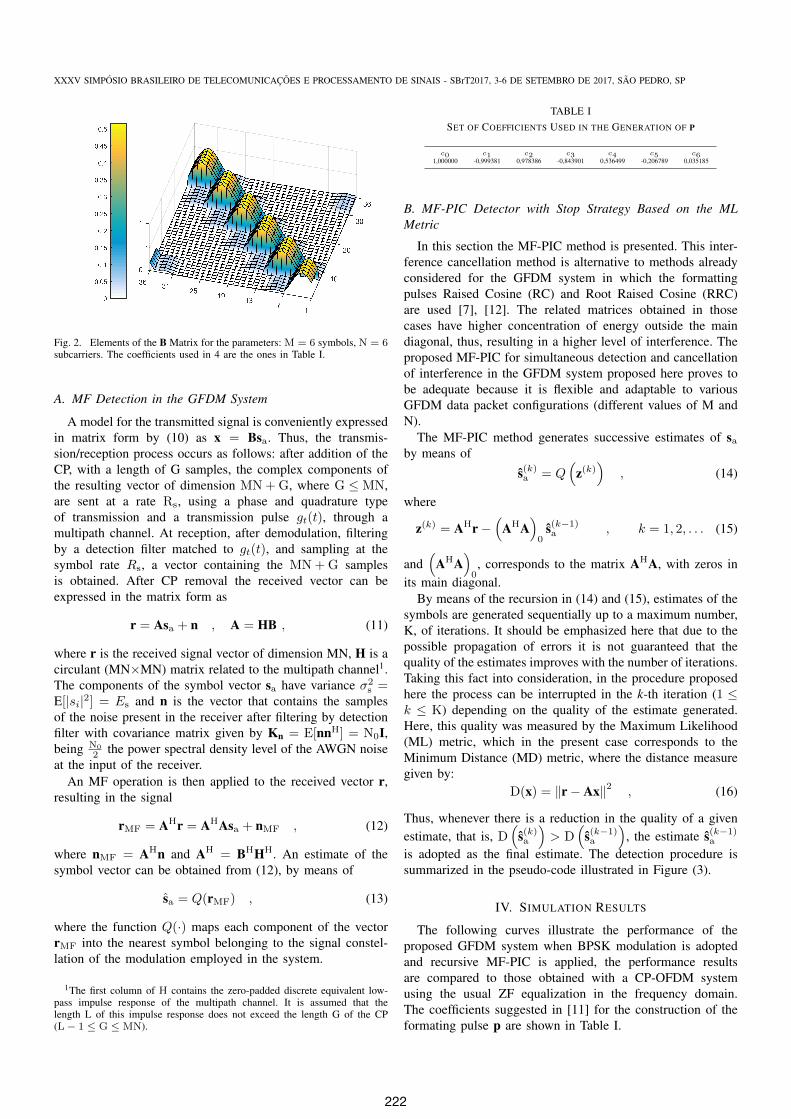
where sa, is the vector that stacks the M vectors of N symbolsorganized in the GFDM information package as shown in theexample of Figure 1 (b). Figure 2 illustrates the componentsof the matrix B for a particular choice of parameters.
III. JOINT DETECTION AND SUBCARRIER INTERFERENCECANCELLATION IN THE GFDM TRANSMISSION SYSTEM
In this section the MF detection method for GFDM systemsis presented. In addition, a preliminary analysis of the parallelinterference cancellation method, PIC, is performed.
221
XXXV SIMPOSIO BRASILEIRO DE TELECOMUNICACOES E PROCESSAMENTO DE SINAIS - SBrT2017, 3-6 DE SETEMBRO DE 2017, SAO PEDRO, SP
Fig. 2. Elements of the B Matrix for the parameters: M = 6 symbols, N = 6subcarriers. The coefficients used in 4 are the ones in Table I.
A. MF Detection in the GFDM System
A model for the transmitted signal is conveniently expressedin matrix form by (10) as x = Bsa. Thus, the transmis-sion/reception process occurs as follows: after addition of theCP, with a length of G samples, the complex components ofthe resulting vector of dimension MN+G, where G ≤ MN,are sent at a rate Rs, using a phase and quadrature typeof transmission and a transmission pulse gt(t), through amultipath channel. At reception, after demodulation, filteringby a detection filter matched to gt(t), and sampling at thesymbol rate Rs, a vector containing the MN+G samplesis obtained. After CP removal the received vector can beexpressed in the matrix form as
r = Asa + n , A = HB , (11)
where r is the received signal vector of dimension MN, H is acirculant (MN×MN) matrix related to the multipath channel1.The components of the symbol vector sa have variance σ2
s =E[|si|2] = Es and n is the vector that contains the samplesof the noise present in the receiver after filtering by detectionfilter with covariance matrix given by Kn = E[nnH] = N0I,being N0
2 the power spectral density level of the AWGN noiseat the input of the receiver.
An MF operation is then applied to the received vector r,resulting in the signal
rMF = AHr = AHAsa + nMF , (12)
where nMF = AHn and AH = BHHH. An estimate of thesymbol vector can be obtained from (12), by means of
sa = Q(rMF) , (13)
where the function Q(·) maps each component of the vectorrMF into the nearest symbol belonging to the signal constel-lation of the modulation employed in the system.
1The first column of H contains the zero-padded discrete equivalent low-pass impulse response of the multipath channel. It is assumed that thelength L of this impulse response does not exceed the length G of the CP(L− 1 ≤ G ≤ MN).
TABLE ISET OF COEFFICIENTS USED IN THE GENERATION OF P
c0 c1 c2 c3 c4 c5 c61,000000 -0,999381 0,978386 -0,843901 0,536499 -0,206789 0,035185
B. MF-PIC Detector with Stop Strategy Based on the MLMetric
In this section the MF-PIC method is presented. This inter-ference cancellation method is alternative to methods alreadyconsidered for the GFDM system in which the formattingpulses Raised Cosine (RC) and Root Raised Cosine (RRC)are used [7], [12]. The related matrices obtained in thosecases have higher concentration of energy outside the maindiagonal, thus, resulting in a higher level of interference. Theproposed MF-PIC for simultaneous detection and cancellationof interference in the GFDM system proposed here proves tobe adequate because it is flexible and adaptable to variousGFDM data packet configurations (different values of M andN).
The MF-PIC method generates successive estimates of saby means of
s(k)a = Q(
z(k))
, (14)
where
z(k) = AHr−(
AHA)0
s(k−1)a , k = 1, 2, . . . (15)
and(
AHA)0, corresponds to the matrix AHA, with zeros in
its main diagonal.By means of the recursion in (14) and (15), estimates of the
symbols are generated sequentially up to a maximum number,K, of iterations. It should be emphasized here that due to thepossible propagation of errors it is not guaranteed that thequality of the estimates improves with the number of iterations.Taking this fact into consideration, in the procedure proposedhere the process can be interrupted in the k-th iteration (1 ≤k ≤ K) depending on the quality of the estimate generated.Here, this quality was measured by the Maximum Likelihood(ML) metric, which in the present case corresponds to theMinimum Distance (MD) metric, where the distance measuregiven by:
D(x) = ‖r− Ax‖2 , (16)
Thus, whenever there is a reduction in the quality of a givenestimate, that is, D
(s(k)a
)> D
(s(k−1)a
), the estimate s(k−1)a
is adopted as the final estimate. The detection procedure issummarized in the pseudo-code illustrated in Figure (3).
IV. SIMULATION RESULTS
The following curves illustrate the performance of theproposed GFDM system when BPSK modulation is adoptedand recursive MF-PIC is applied, the performance resultsare compared to those obtained with a CP-OFDM systemusing the usual ZF equalization in the frequency domain.The coefficients suggested in [11] for the construction of theformating pulse p are shown in Table I.
222
XXXV SIMPOSIO BRASILEIRO DE TELECOMUNICACOES E PROCESSAMENTO DE SINAIS - SBrT2017, 3-6 DE SETEMBRO DE 2017, SAO PEDRO, SP
Capıtulo 5. Detectores com Cancelamento de Interferencias em Paralelo paraSistemas GFDM 62
Data: First estimate of the GFDM symbols(s(0)
a
)
Result: Final estimate of the GFDM symbols (saf)
START
do D(s(0))
% Performs the MD0 metric
do Saves MD0
for k = 1, 2, . . . ,K do
Performs the PIC, (15)
Q(·) Estimate the symbols, (14)
Save the estimate s(k)a
D(s(k)
a
)% Performs the MDk metric
% Compare the saved metric with the present metric
if MDk > MDk−1 then
Stops the process and provides the estimate saf = s(k−1)a
end
end
Provides the estimate saf = s(K)a
END
5.2
Detector ZF com PIC Recursivo e Escolha da Ultima Estimativa Geradaque Precede um Aumento na Metrica MD
Vale ressaltar que o detector ZF com PIC recursivo pode ser aplicado di-
retamente no sistema descrito na Subsecao 5.1.3. E estudada esta configuracao
porque, como visto no Capıtulo 3, mesmo sendo mais complexo na sua imple-
mentacao. O detetor ZF fornece a melhor primeira estimativa dentre os detec-
tores estudados, assim e interessante observar o desempenho final do sistema
quando o PIC recursivo e aplicado com a estrategia (c) de parada e decisao,
que tem uma menor complexidade dentre as tres propostas. O procedimento
e o mesmo que o indicado pelo Algorıtmo 3, com a primeira estimativa que
alimenta o PIC obtida por meio do detector ZF.
5.3Resultados de Simulacoes
Nesta secao e analisado o desempenho do sistema GFDM em termos da
taxa de erro por sımbolo de transmissao (SER), frente a relacao sinal ruıdo
Fig. 3. Algorithm for signal detection in the GFDM system using the MF-PICtechnique and the ML metric.
TABLE IICHANNEL MODELS
Channel Discrete impulse response Delay
AWGN h0 = 1 0
Multipath Channel h0i= 10
( −iL−1
)i=1,2,··· ,L−1 L− 1
In the simulations the impulse response of the multipathchannel is normalized to unitary energy (‖h‖2 = 1), h = h0
‖h0‖ ,and the length of the CP guard band is given by G = L−1. Themultipath channel model used and the simulation parametersare summarized in the tables II and III.
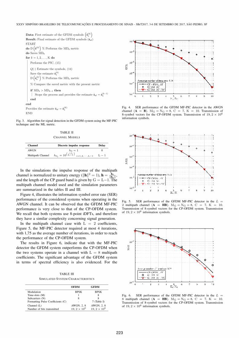
Figure 4, illustrates the information symbol error rate (SER)performance of the considered systems when operating in theAWGN channel. It can be observed that the GFDM MF-PICperformance is very close to that of the CP-OFDM system.We recall that both systems use 8-point iDFTs, and thereforethey have a similar complexity concerning signal generation.
In the multipath channel case with L = 2 coefficients,Figure 5, the MF-PIC detector required at most 4 iterations,with 1,75 as the average number of iterations, in order to reachthe performance of the CP-OFDM system.
The results in Figure 6, indicate that with the MF-PICdetector the GFDM system outperforms the CP-OFDM whenthe two systems operate in a channel with L = 8 multipathcoefficients. The significant advantage of the GFDM systemin terms of spectral efficiency is also evidenced. For the
TABLE IIISIMULATED SYSTEM CHARACTERISTICS
OFDM GFDM
Modulation BPSK BPSKTime-slots (M) 1 8Subcarriers (N) 8 8Formatting Pulse Coefficients (C) - 7 (Table I)Channel (L) AWGN, 2, 8 AWGN, 2, 8Number of bits transmitted 19, 2× 10⁶ 19, 2× 10⁶
Fig. 4. SER performance of the GFDM MF-PIC detector in the AWGNchannel (A = B). MG = NG = 8, C = 7, K = 10. Transmission of8-symbol vectors for the CP-OFDM system. Transmission of 19, 2 × 10⁶
information symbols.
Fig. 5. SER performance of the GFDM MF-PIC detector in the L =2 multipath channel (A = HB). MG = NG = 8, C = 7, K = 10.Transmission of 8-symbol vectors for the CP-OFDM system. Transmissionof 19, 2× 10⁶ information symbols.
Fig. 6. SER performance of the GFDM MF-PIC detector in the L =8 multipath channel (A = HB). MG = NG = 8, C = 7, K = 10.Transmission of 8-symbol vectors for the CP-OFDM system. Transmissionof 19, 2× 10⁶ information symbols.
223

XXXV SIMPOSIO BRASILEIRO DE TELECOMUNICACOES E PROCESSAMENTO DE SINAIS - SBrT2017, 3-6 DE SETEMBRO DE 2017, SAO PEDRO, SP
TABLE IVCOMPARISON OF COMPLEXITY FOR DIFFERENT GFDM TRANSMITTERS
TechniqueNumber ofComplex
Multiplications
ResultsM = N = 8
ResultsM = N = 64
Direct B arraymultiplication (MN)2 4096 16777216
GFDM transmitterproposed in [13]∗
MN(log2N +2log2M + X)
704 81929
GFDM transmitterproposed in [14]
MN2 (log2N + M) 352 143360
GFDM transmitterused in this work
MN2 (log2N + 4) 224 20480
∗ A typical value for parameter X is 2, [13].
channel with L = 8 coefficients and G = 7, for example,the spectral efficiency of the CP-OFDM system is ηOFDM =
NN+G = 8
8+7∼= 0, 533(bits/s/Hz), and for the GFDM system
we have ηGFDM = MNMN+G = 64
64+7∼= 0, 901(bits/s/Hz), thus
achieving a spectral efficiency 1,7 times higher than the CP-OFDM system.
A direct comparison of the computational complexity of theGFDM transmitter used in this work with implementations ofthe transmitter presented in previous works is illustrated inTable IV.
V. CONCLUSIONS
In this work, we have presented and discussed a detec-tion technique employing matched filtering and parallel in-terference cancellation to be used in GFDM systems. Thematrix model for the GFDM transmitted signals, presentedin Section II, allowed the analysis of MF detector perfor-mance. Moreover, we have analyzed the performance of theproposed method of interference cancellation, which is neededto minimize the ICI and ISI interference originated by the non-orthogonality of the GFDM subcarriers.
Besides offering a substantially higher gain in terms ofspectral efficiency, especially for large channel delays, wehave verified that the proposed method of detection MF-PICfor the GFDM systems has a performance, in terms of SER,almost identical to that of the CP-OFDM in environments withlow channel delays and even superior with higher channeldelays. It is worth noting that, unlike previously suggestedimplementations, the proposed method of detection does notrequire channel matrix inversions therefore reducing its imple-mentation complexity.
REFERENCES
[1] Michailow N., Matthe M., Gaspar I.S., Caldevilla A.N., Mendes L.L.,Festag A., & Fettweis G., Generalized Frequency Division Multiplexingfor 5th Generation Cellular Networks, in IEEE Transactions on Com-munications, vol. 62, no. 9, (2014), pp. 3045–3061, ISSN 0090-6778,doi:10.1109/TCOMM.2014.2345566, September 2014.
[2] Farhang A., Marchetti N., Figueiredo F., & Miranda J.P., Massive MIMOand Waveform Design for 5th Generation Wireless CommunicationSystems, pp. 70–75, doi:10.4108/icst.5gu.2014.258195, November 2014.
[3] Chen S. & Zhao J., The Requirements, Challenges, and Technologies for5G of Terrestrial Mobile Telecommunication, in IEEE CommunicationsMagazine, vol. 52, no. 5, (2014), pp. 36–43, ISSN 0163-6804, doi:10.1109/MCOM.2014.6815891, May 2014.
[4] Akyildiz I.F., Melodia T., & Chowdury K.R., Wireless Multime-dia Sensor Networks: A survey, in IEEE Wireless Communica-tions, vol. 14, no. 6, (2007), pp. 32–39, ISSN 1536-1284, doi:10.1109/MWC.2007.4407225, December 2007.
[5] Banelli P., Buzzi S., Colavolpe G., Modenini A., Rusek F., & UgoliniA., Modulation Formats and Waveforms for 5G Networks: Who will bethe heir of OFDM?: An overview of alternative modulation schemesfor improved spectral efficiency, in IEEE Signal Processing Mag-azine, vol. 31, no. 6, (2014), pp. 80–93, ISSN 1053-5888, doi:10.1109/MSP.2014.2337391, November 2014.
[6] Wunder G., Jung P., Kasparick M., Wild T., Schaich F., Chen Y.,Brink S.T., Gaspar I., Michailow N., Festag A., Mendes L., Cas-siau N., Ktenas D., Dryjanski M., Pietrzyk S., Eged B., Vago P.,& Wiedmann F., 5GNOW: Non-Orthogonal, Asynchronous Waveformsfor Future Mobile Applications, in IEEE Communications Maga-zine, vol. 52, no. 2, (2014), pp. 97–105, ISSN 0163-6804, doi:10.1109/MCOM.2014.6736749, February 2014.
[7] Alves B.M., Mendes L.L., Guimaraes D.A., & Gaspar I.S., Performanceof GFDM Over Frequency-Selective Channels – Invited Paper, Novem-ber 2013.
[8] Gaspar I., Michailow N., Navarro A., Ohlmer E., Krone S., &Fettweis G., Low Complexity GFDM Receiver Based on SparseFrequency Domain Processing, pp. 1–6, ISSN 1550-2252, doi:10.1109/VTCSpring.2013.6692619, June 2013.
[9] Farhang-Boroujeny B. & Moradi H., Derivation of GFDM Basedon OFDM Principles, pp. 2680–2685, ISSN 1550-3607, doi:10.1109/ICC.2015.7248730, June 2015.
[10] Martin K.W., Small Side-Lobe Filter Design for Multitone Data-Communication Applications, in IEEE Transactions on Circuits andSystems II: Analog and Digital Signal Processing, vol. 45, no. 8, (1998),pp. 1155–1161, ISSN 1057-7130, doi:10.1109/82.718830, August 1998.
[11] Mirabbasi S. & Martin K., Overlapped Complex-Modulated Transmulti-plexer Filters with Simplified Design and Superior Stopbands, in IEEETransactions on Circuits and Systems II: Analog and Digital SignalProcessing, vol. 50, no. 8, (2003), pp. 456–469, ISSN 1057-7130, doi:10.1109/TCSII.2003.813592, August 2003.
[12] Michailow N., Lentmaier M., Rost P., & Fettweis G., Integration of aGFDM Secondary System in an OFDM Primary System, pp. 1–8, June2011.
[13] Michailow N., Gaspar I., Krone S., Lentmaier M., & Fettweis G.,Generalized Frequency Division Multiplexing: Analysis of an AlternativeMulti-Carrier Technique for next Generation Cellular Systems, pp. 171–175, ISSN 2154-0217, doi:10.1109/ISWCS.2012.6328352, August 2012.
[14] Farhang A., Marchetti N., & Doyle L., Low Complexity TransceiverDesign for GFDM, January 2015.
224