Embed Size (px)
Citation preview

13.08.2013
Simulation software for the analysis of electrical power networks,
adjustable speed drives and hydraulic systems
EPFL, Swiss Federal Institute of Technology
CH-1015 Lausanne, Switzerland.
Demo version available on the website: http://simsen.epfl.ch
Main features• Graphical input/output
• Modular structure with arbitrary topology
• No restriction on the network size
• Events detection and back-tracking
• Load-Flow calculation
• Initial conditions entirely, partly or not defined
• Stable operating point entirely saved
• Interactive read/write access to any parameter
• Harmonics analysis
• Parameterization
• SI or per unit outputs
• Available tutorials and help-on-line
• Runs under Windows XP/Windows7/32/64bits
Electrical Power Networks• Electrical machines
• Electromagnetic transients in AC/DC networks
• Transient stability and general fault analysis
• SubSynchronous Resonance (SSR)
• Torsional analysis
• FACTS, HVDC, SVC
• Control and regulation
• IEEE Standard excitation systems and PSS
Adjustable Speed Drives• Special machines
• Power electronics converters
• Cyclo-converters
• Voltage Source Inverters (VSI)
• Analog / digital mixed signals
simulation
• Control and regulation
Regulation part• Easy definition of regulation structures
• Programmable unit, logical table
• S-transfer functions, regulator
• Digital devices, Z-transfer functions
• Control devices, ON-LINE FFT
• User defined DLL for control
• Coupling with MATLAB
• Coupling with external application (Labview,
Hardware, etc)
Hydraulic systems• Water hammer calculation
• Turbines 4 quadrants transient behavior
• Francis/Pelton/Kaplan and pump-
turbines
• Pumps
• Surge tanks, surge shafts, differential ST
• PID Turbine governors
• Hydroelectric interactions
• Tidal turbines
• Cavitation/Water column separation
13.08.2013
SIMSEN: History, Users / Partners
A modular software package for the digital simulation
and analysis of power networks and adjustable speed drives
SIMSEN History and development:
The development of this software started in 1992. The idea was to develop a modular
system able to do fast simulations of electrical power systems including semiconductors
and regulation parts. The whole development has been based on practical examples from
power networks and industrial drives. In both domains, the customer came with problems
requiring the study of complex systems. In 1994, it was decided do develop an
input/output interface. Thus other people could use the system. SIMSEN is sold since
1996. From 1996 to 1998, the system has been extended to simulate the digital behavior
of the regulation part. The present version is able to simulate correctly mixed-signals
systems (systems with analog and digital elements). Results provided by SIMSEN have
been validated by comparison with measurements in industrial projects. Since 2001,
SIMSEN is extended to hydraulic components for the modeling of hydraulic installations
and of entire hydroelectric power plants: SIMSEN-Hydro.
SIMSEN Users / Partners:
ALSTOM Power Generation Ltd., Birr, Switzerland, Hydropower generation: on site world wide license
ALSTOM Power Generation Ltd., Birr, Switzerland, Turbo generators
ALSTOM Power Conversion Ltd., Belfort, France: Power Electronics and Adjustable Speed Drives
ABB Industry, Turgi, Switzerland, Power Electronics and Adjustable Speed Drives: on site Swiss license
ABB Industri AS Norway: Power Electronics and Adjustable Speed Drives
ABB (China) Ltd, Shanghai Branch, Shanghai, China
ABB Pte Ltd, Singapore
ALSTOM Hydro France Ltd., Grenoble, France
VOITH Hydro Holding GmbH, Heidenheim, Germany : on site world wide license
ANDRITZ Hydro AG, Switzerland, Austria
Litostroj Power d.o.o, Ljubljana, Slovenia
IMPSA Hydro, Mendoza, Argentina
Vetco Gray, Billingstad, Norway
ANSALDO Energia s.p.a. Italy : Power generation
WEIDMANN Transformer board AG, Rapperswil, Switzerland
Utilities: EOS, BKW, GROUPE E, SEL, SIG
AF-Consult Switzerland Ltd., Baden, Switzerland
Tractebel Eng. Coyne et Bellier, Gennevilliers, France
Lombardi Ltd, Minusio, Switzerland
Hydro Exploitation, Sion, Switzerland
IM Ingegneria Maggia SA, Locarno, Switzerland
ISL Ingénierie, Lyon, France
Power Vision Engineering sàrl, Ecublens, Switzerland
Hidroinstitut, Ljubljana, Slovenia
EDF-CIH, Le Bourget-du-Lac, France

13.08.2013
SIMSEN-Electro: Presentation
Electrical systems simulation features of SIMSEN :
• Mixed analog-digital simulation of electrical systems.
• Modular structure enabling simulations of power systems with arbitrary topology in transient or steady-state
conditions.
• Parameterization of components and modularity enables to built complex sub-models of new components.
• Analysis of the dynamic behavior of complex electrical systems comprising electrical machines, power electronics
converters and typical power system components (transmission line,..)
• Calculation of stable initial conditions with load-flow procedure.
• Possibility to interact with external programs or devices
• Has been validated by comparison with measurement on many industrial cases.
• Example of application: HVDC system, fault recovery after short circuit on the AC grid
• Voltage and current at the DC-link level during the fault
• Currents on the AC grid during recovery
• Control of the rectifier

13.08.2013
SIMSEN-Electro: List of available units
Electrical machines
Three-phase synchronous, single-phase synchronous,
6-phase synchronous, three-phase generalized,
three-phase induction with wound rotor, three-phase
induction with squirrel cage rotor, two-phase induction,
three-phase permanent magnet, DC motor,
mechanical mass, stator mass
Three-phase elements
Voltage supply, transmission lines,
circuit breaker, phase shifting transformer,
transformer with three windings, load
Three-phase converters
Rectifier (diode), current converter (thyristor),
voltage inverter (thyristor GTO), current variator
(thyristor)
Single-phase elements
Voltage supply, Resistor, inductor,
capacitor, varistor,
circuit breaker, linked inductor,
transformer
Semiconductors
Diode, thyristor, thyristor GTO, thyristor GTO + diode, triac,
IGBT
Analog function units
Program, S-transfer functions, regulator, logical table, points
function, external DLL
Digital function units
Averager, sample, limiter, pulse
generator, Z-transfer function,
hysteresis, on-line FFT

13.08.2013
SIMSEN-Hydro: Presentation
Hydraulic Extension of SIMSEN :
• Modeling of hydraulic components based on electrical analogy.
• Based on a modular structure enabling digital simulations of the behavior in transient or steady-state conditions of
entire hydroelectric power plant with arbitrary topology.
• One set of differential equations including hydraulic components, mechanical masses, electrical units and control
devices ensures that the hydroelectric interactions are properly taken into account.
• Parameterization of components and modularity enables to built up complex sub-models of new components.
• Analysis of dynamic behavior of complex piping systems.
• Example of application: total load rejection of a 2 Francis turbine units power plant
• Out of phase synchronization of unit 1…
… Effects on unit 2
Surge tank transients
Unit 1 transients

13.08.2013
SIMSEN-Hydro: List of available units
Hydraulic Extension of SIMSEN :
Hydraulic Units:
• Reservoir
• Pipe
• Viscoelastic Pipe
• Valves
• Discrete Losses
• Surge Tank, Surge Shaft, Surge Vessel
• Air vessel
• Cavitation Compliance with
Mass Flow Gain Factor
• Pressure Sources
• Pumps
• Francis Pump-Turbine
• Pelton Turbine
• Kaplan Turbine
• Propoeller turbines
Turbine models based
on turbine characteristics
Pipe model based on
electrical equivalent
Momentum and mass conservation
equations provide a set of hyperbolic
partial differential equations solved by
finite difference method using centered
and Lax scheme leading to an equivalent
electrical circuit modeling a pipe of
length dx. The capacitance, inductance
and resistance respectively accounts for
compressibility, inertia and losses effects.

13.08.2013
SIMSEN: New features of version 2.2.10
New features of SIMSEN :
• Calculation speed improvement (at least 2 times faster).
• Equations parser in main file and in new unit PROG.
• ON-LINE Fast Fourier Transform (FFT)
• User defined DLL for control
(C++, PASCAL, etc…)
• New output interface VISUAL 2.2
• Synchronous machine parameters
conversion from characteristic quantities
to equivalent circuit diagram
13.08.2013
SIMSEN: New features of version 2.3
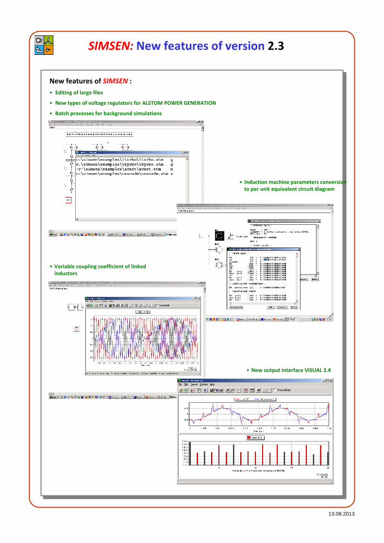
New features of SIMSEN :
• Editing of large files
• New types of voltage regulators for ALSTOM POWER GENERATION
• Batch processes for background simulations
• Variable coupling coefficient of linked
inductors
• New output interface VISUAL 2.4
• Induction machine parameters conversion
to per unit equivalent circuit diagram

13.08.2013
SIMSEN: Ongoing and future developments
Ongoing and future developments of SIMSEN :
New input interface
Graphical features updated to Windows 64 bits standards
Extended Parser: command language, programmable unit
Calculation windows and drawings (for documentation)
Graphical connections for control (user customized)
User-defined models
Modeling
More detailed semiconductors (Spice Models)
Cables, Transmission Lines (Propagation phenomena)
Saturation with magnetic circuits models (Transformers)
Open Channels
Propellers
Discharge source
Inclined surge shaft
Analysis
Eigen Values, Eigen Vectors Calculation and Representation
Harmonic analysis
DSP code generation
Automatic generation of DSP code for control systems
Simulation system
AC analysis
Load-Flow with semiconductors
LINUX Version
New Modules of SIMSEN :
Water column separation
Wind turbine
Tidal turbine
Surface functions
Coupling with CFX and ANSYS
Coupling with MATLAB
Coupling with external application (labview, Hardware, etc)

13.08.2013
SIMSEN-Electro: SubSynchronous Resonance (SSR)
This example shows the possibilities of
SIMSEN to take into account correctly the
electrical and mechanical interactions in
power systems. The SubSynchronous
Resonance (SSR) is an important problem in
compensated power networks. Due to a
change of topology or impedance of the
compensated network, electrical resonance
may match the mechanical resonance in the
shaft of large generators. Such a resonance
may destroy the whole shaft of generators.
The example is based on an IEEE paper about
SSR. The main goal of this simulation is to
check the computed results with analytical
investigations. Additionally, the simulation
has been compared with a specific program
developed only to analyze SSR. SIMSEN and
the special program gave exactly the same
results.
The black curve presents the results
obtain by a specific program developed to
analyze SSR problems.
13.08.2013
SIMSEN-Electro: Back to back start-up
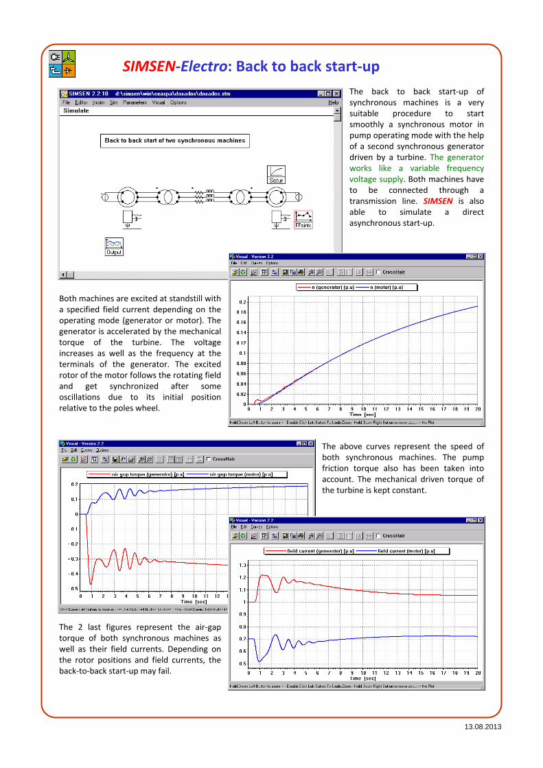
The back to back start-up of
synchronous machines is a very
suitable procedure to start
smoothly a synchronous motor in
pump operating mode with the help
of a second synchronous generator
driven by a turbine. The generator
works like a variable frequency
voltage supply. Both machines have
to be connected through a
transmission line. SIMSEN is also
able to simulate a direct
asynchronous start-up.
Both machines are excited at standstill with
a specified field current depending on the
operating mode (generator or motor). The
generator is accelerated by the mechanical
torque of the turbine. The voltage
increases as well as the frequency at the
terminals of the generator. The excited
rotor of the motor follows the rotating field
and get synchronized after some
oscillations due to its initial position
relative to the poles wheel.
The above curves represent the speed of
both synchronous machines. The pump
friction torque also has been taken into
account. The mechanical driven torque of
the turbine is kept constant.
The 2 last figures represent the air-gap
torque of both synchronous machines as
well as their field currents. Depending on
the rotor positions and field currents, the
back-to-back start-up may fail.

13.08.2013
This example shows the possibilities of SIMSEN
to simulate multi-machines interactions in
power systems. Therefore, the user can build
the mechanical shaft including an unlimited
number of masses. These masses are connected
together with springs and damping elements. A
mechanical shaft can even contain several
machines. The saturation effect of the main
magnetic circuits of the machines are modeled.
The transformer models are able to take into
account the phase shifting between the primary
and the secondary sides. The regulation part
consists on four voltage regulators acting on
each synchronous generator. The fault is
generated by using a circuit-breaker. The
ON/OFF orders can be easily defined by the user.
All the initial conditions are automatically
calculated using an additional Load-Flow
program (rotor angle positions, mechanical
angles and excitation current). Single-phase
faults can also be simulated by defining ground
connections.
The simulation results can be used for a
torsional analysis in which the mechanical
stresses can be investigated. All the electrical
and mechanical computed values are available
without any special scope definition.
SIMSEN-Electro: Short circuit in a large power plant
As the synchronous machine model is taking
into account the sub-subtransient reactance, it
is possible to respect the real transient behavior
of a large generator, specially in network faults
analysis.

13.08.2013
This example illustrates the potential of
SIMSEN to simulate large power networks (No
restriction on the network size). The
additional Load-Flow program calculates
automatically all the initial conditions (Phase
currents, field currents and rotor positions of
synchronous machines). The results can be
used to determine the transient stability of
the entire network.
SIMSEN-Electro: Transient stability in a large power network
The simulation results show the transient
behavior of a large 465 MVA hydro-generator
after a three-phase short-circuit on a 400 kV
transmission line. All the results for all the
elements present in the network can be saved
and analyzed after the computation. The
Load-Flow operating point has been compared
successfully with measurements.

13.08.2013
This example illustrates the
possibility of SIMSEN to
simulate complex HVDC
networks including power
plants, 12-pulse thyristors
converters, filters, SVC and all
the control and regulation
devices. Both rectifier and
inverter of the HVDC are
modeled with all the
semiconductors. Three -
windings transformers also are
taken into account on both
sides of the HVDC. They allow
the 30° phase shifting for 12-
pulse operation.
For large and complex networks, SIMSEN offers
the possibility to add, replace or remove
components without restarting the simulation
from zero. This great advantage allows the study
of networks including a large number of electrical
components. The user can build his example step
by step by adding elements and restabilizing the
circuit.
When the system is stable enough, the user can
add circuit breakers (or other elements) and
define faults to be simulated. Once done, it is
possible to continue the simulation with saved
initial conditions. For that special example, it is
possible to analyze the fault recovery after a
short circuit at the rectifier AC grid. In this goal,
the regulation contains special functions like
VDCOL (Voltage Dependant Current Order
Limitation). This functions allow a smooth
recovery of the HVDC.
SIMSEN-Electro: HVDC network with SVC
The rectifier and inverter regulation is completely
modeled, especially the extinguishing angle
regulation of the inverter. Simulation results
show the behavior of the HVDC after a three-
phase short circuit at the rectifier AC grid (power
plants).

13.08.2013
SIMSEN-Electro: Three-level Voltage Source Inverter (VSI)
This example is based on a real industrial
application in the field of Medium Voltage
Drives (MVD). It is very important to
simulate correctly the three-level inverter
with all the semiconductors. The inverter is
tuned by a Direct Torque Control (DTC).
The entire regulation has been
implemented taking into account the real
digital behavior.
The entire system has been modeled
using more than 200 units to simulate
correctly the flux estimation, the DTC
with multi-level hysteresis control, the
switching frequency control, speed
control. This example shows the potential
of SIMSEN to simulate mixed signals.
Simulation results present the step
response behavior of the drive.
t__inv_ref, t__inv, t__sta, u__dc [p.u.]
-0.2
0
0.2
0.4
0.6
0.8
1
1.2
1.4
0 0.005 0.01 0.015 0.02 0.025 0.03 0.035 0.04 0.045 0.05
Time [s]
Measurements
13.08.2013
SIMSEN-Electro: Slip-energy recovery drive VARSPEED
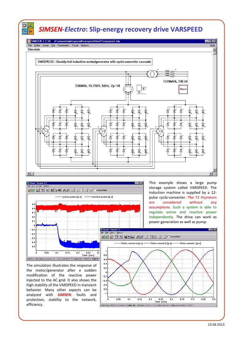
This example shows a large pump
storage system called VARSPEED. The
induction machine is supplied by a 12-
pulse cyclo-converter. The 72 thyristors
are considered without any
assumptions. Such a system is able to
regulate active and reactive power
independently. The drive can work as
power generation as well as pump.
The simulation illustrates the response of
the motor/generator after a sudden
modification of the reactive power
injected to the AC grid. It also shows the
high stability of the VARSPEED in transient
behavior. Many other aspects can be
analyzed with SIMSEN: faults and
protection, stability to the network,
efficiency.

13.08.2013
SIMSEN-Electro: 12-pulse Load Commutated Inverter (LCI)
This example presents a large
industrial adjustable speed
drive. The Load Com-mutated
Inverter (LCI) is supplying large
synchronous machines having 6
phases. Thus, the 6th harmonic
of the air-gap torque is automa-
tically eliminated by the 12
pulse inverter. The system is
taking into account all the
regulation parts, the 6-phase
synchronous machine, the
mechanical shaft and the
frequency converter. The
mechanical load corresponds to
a 20 MW fan for wind tunnel
applications.
The simulation results show the response
of the system after a change of the speed
set value. The load represents a large fan
and has been modeled with a square
function of the speed. The simulation has
been used to perform a torsional analysis
and to design the inverter in function of the
extinguishing angle of the inverter at full
load.
Results have been compared successfully
with a real 20 MW drive. The displayed
curves presents the stator currents and the
field current, the air-gap torque and motor
speed, the voltage and current on a
thyristor valve.
The 6-phase synchronous machine model
has been especially developed for such
kind of drives using 12-pulse converters.

13.08.2013
SIMSEN-Electro: STATCOM (STATic COMpensator)
This example presents a FACTS
(Flexible Alternative Current
Transmission Systems) based on a
three-level VSI (Voltage Source
Inverter) working as a Static Var
Compensator (SVC). The goal of
such a system is to provide reactive
power to a high voltage
transmission line in order to keep
its voltage level to a specified value.
The advantage of the three-level VSI
is the reduction of its output
current harmonics without
increasing the switching frequency
of the valves (Thyristors GTO or
IGCT, Integrated Gate Control
Thyristor).
To achieve these performances, an efficient
regulation part has been implemented. It contains a
PLL (Phase Locked Loop), a special control with high
modulation index, a reduced switching frequency of
the valves with high frequency carrier signal and
PWM (Pulse Width Modulation) control.
SIMSEN is able to take into account the real
topology of a FACTS device with all the
semiconductors. This provides the user with a
detailed analysis of his system. The ON-LINE FFT
has been applied to the transformer line current.
Its results have been compared successfully with
the harmonics analysis.
The user may implement and investigate several
control methods in order to compare the results.
Once the VSI has been successfully implemented
and checked, the studied system may be extended
with network elements (machines, lines,
transformers, a.s.o) to investigate in details the
behavior of FACTS devices in a high voltage AC
network. SIMSEN is able to simulate large networks.
13.08.2013
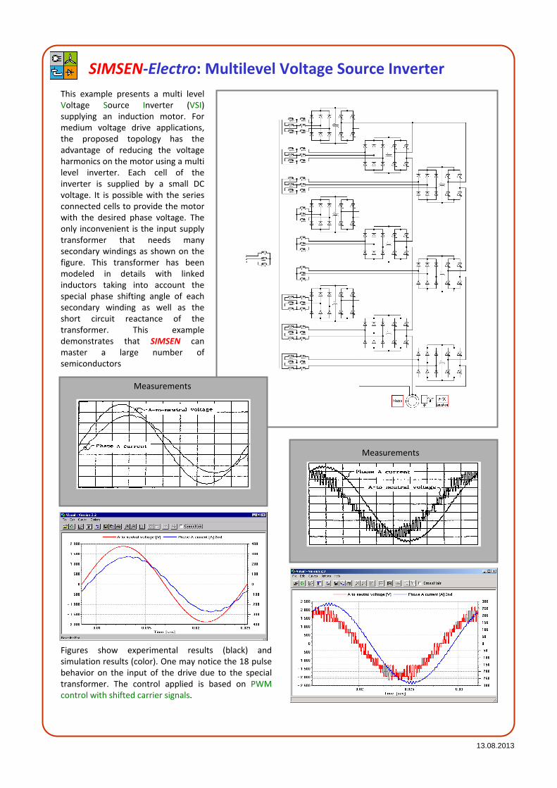
SIMSEN-Electro: Multilevel Voltage Source Inverter
This example presents a multi level
Voltage Source Inverter (VSI)
supplying an induction motor. For
medium voltage drive applications,
the proposed topology has the
advantage of reducing the voltage
harmonics on the motor using a multi
level inverter. Each cell of the
inverter is supplied by a small DC
voltage. It is possible with the series
connected cells to provide the motor
with the desired phase voltage. The
only inconvenient is the input supply
transformer that needs many
secondary windings as shown on the
figure. This transformer has been
modeled in details with linked
inductors taking into account the
special phase shifting angle of each
secondary winding as well as the
short circuit reactance of the
transformer. This example
demonstrates that SIMSEN can
master a large number of
semiconductors
Figures show experimental results (black) and
simulation results (color). One may notice the 18 pulse
behavior on the input of the drive due to the special
transformer. The control applied is based on PWM
control with shifted carrier signals.
Measurements
Measurements

13.08.2013
SIMSEN-Electro: 3-level UPFC (Unified Power Flow Controller)
This example presents a 3-level
UPFC (Unified Power Flow
Controller). It concists of two 3-
level VSI (Voltage Source
Inverter) connected to the same
DC-link. The first VSI is shunt
connected to the AC bus. It
works like a STATCOM in order
to maintain the voltage on the
AC node. The second VSI is serial
connected to the transmission
line. It can insert a regulated
serial voltage in the transmission
line.
Inserting this serial voltage in the transmission
line, it is possible to modify the relative
impedance of the transmission line, and thus to
require the transmitted active and reactive
power independently. The AC bus voltage
maintain is also a great advantage of the UPFC.
The curves represent a step response of active
and reactive power in the transmission line. It is
impressive to observe the high dynamic of the
regulation even in such a case of high power
UPFC (160 MVA, 6 kV DC, 50 Hz). The current in
the transmission line contains only few
harmonics (THD < 2%).
Again, this example shows the potential of
SIMSEN to simulate in details power systems
including power electronics devices. Such
power network studies are going to be more
and more important in the future. It is
essential to take into account the power
elements with three-phase modeling and the
complete regulation in order to perform a
right harmonics analysis.

13.08.2013
SIMSEN-Electro: Doubly-fed induction
motor/generator with 3-level VSIThis example presents a
Doubly-fed Asynchronous
Machine (DASM). The rotor
cascade is made of 2 3-level
Voltage Source Inverter (VSI)
for large pump storage plants.
In comparison with the
standard cyclo-converter
cascade, the VSI cascade
represents many advanta-ges:
less power components,
harmonics reduction, high
dynamic and reactive power
compensation.
The whole power circuit as well as the complete
regulation part have been implemented in
SIMSEN. The control part includes the
transformer control: exchange of active and
reactive power, the machine control: speed
regulation, stator and rotor current controls
and the DC-link voltages control. Both VSI are
tuned with improved PWM shape.
The simulation results present the behavior of
the system after a 100% single phase voltage
drop at the high voltage side of the main
transformer. SIMSEN appeared to be a
powerful simulation system, especially when
reconnecting the cascade transformer to the AC
grid. This allows to estimate correctly the global
power plant current.
Another important point of the control is the
respect of the switching frequency limit of the
new hard-driven GTO’s. This has been taken
into account in the control. Swithing
frequencies of 250 Hz on the transformer side
(see beside figure) and 500 Hz on the rotor side
have been required. Even with these low
switching frequency values, the calculated THD
of both stator and main transformer currents
lead to values lower than 1%.

13.08.2013
SIMSEN-Electro: Synchronous motor fed by a
12-pulse cyclo-converterThis example presents a
synchronous motor fed by
a 12-pulse cyclo-converter.
The circuit includes a long
trans-mission line as well
as the harmonics filters
bank. It is possible to
analyze the line-filter
interaction. The 12-pulse
cyclo-converter is com-
mutated by the AC
network. Each DC-link
supplies a phase of the
synchronous motor. The
field current rectifier is also
taken into account. The
control scheme is based on
a dynamic flux model of
the synchro-nous machine.
It allows a very high
dynamic, even if that kind
of drive has a very low
supply frequency.
The simulation results present the
behavior of the system in steady-state
at rated operating point as well as a
load change from 50% to 100% at
rated speed. SIMSEN is able to
simulate such a complex topology,
including more than 210 differential
equations. Values rela-ted to each
semiconductor can be displayed.
Netwok quantities are also available
(active and reactive power, current
harmonics, aso…). The great advantage
of SIMSEN in that kind of example is
the possibility to analyze a large power
system taking into account all the
semiconductors. The influence of each
power electronics element can be
estimated. This feature is a powerful
advantage to analyze the power
systems of the future, including more
and more power electronics.

13.08.2013
SIMSEN-Electro: Induction motor fed by current converter
This example presents an
induction motor fed by a
current converter. This is a
special frequency
converter including ad-
ditional capacitors in order
to extinguish the current of
the thyristors. This leads to
very fast transients and to
the typical form of
terminal voltages on the
motor side. To validate the
accuracy of SIMSEN,
measurements have been
recorded on a real 280 kW
drive.
The results present the behavior of the system
in steady-state at 97% of the rated operating
point. The red curves correspond to the
SIMSEN computed results and the blue curves
to the measurements. On the right side, the
terminal voltage of the motor is displayed.
Due to the presence of the extinguishing
capacitors, the voltage presents peaks during
each commutation. The simulation matches
the measurements.
On the right side, the air-gap torque is
displayed. It has been measured through a
digital torque measurement device. This
device is based on electrical signals and allows
measuring low and high fre-quencies
components in the air-gap torque of electrical
machines. The simulation results match the
measurements. This example shows the
precision of the modeling in SIMSEN.
On the left side, the phase currents of the
motor are displayed. They present the
typical 120° wave form of the current
converter. This kind of drive is very sensitive
to the DC link reactor. It is responsible for
the stability of the drive.
13.08.2013
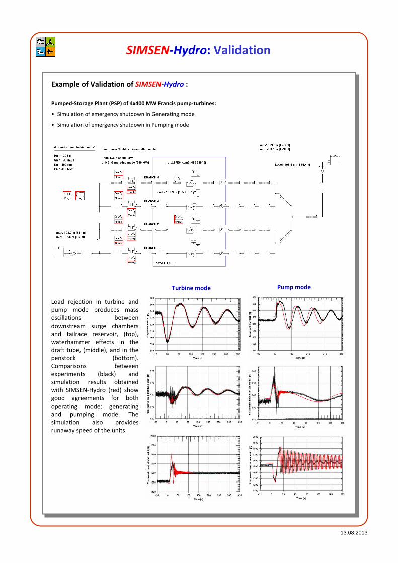
SIMSEN-Hydro: Validation
Example of Validation of SIMSEN-Hydro :
Pumped-Storage Plant (PSP) of 4x400 MW Francis pump-turbines:
• Simulation of emergency shutdown in Generating mode
• Simulation of emergency shutdown in Pumping mode
Turbine mode Pump mode
Load rejection in turbine and
pump mode produces mass
oscillations between
downstream surge chambers
and tailrace reservoir, (top),
waterhammer effects in the
draft tube, (middle), and in the
penstock (bottom).
Comparisons between
experiments (black) and
simulation results obtained
with SIMSEN-Hydro (red) show
good agreements for both
operating mode: generating
and pumping mode. The
simulation also provides
runaway speed of the units.

13.08.2013
SIMSEN-Hydro: Hydroelectric transients
Example with SIMSEN-Hydro :
Tripping of a 200 MW consumer load in an islanded power network comprising:
• 1 GW Hydroelectric power plant including 4x250 MW Francis turbines, long penstock and surge tank
• 1 to 4 thermal power plants of 1.3 GW including, high pressure, 2 low pressure steam turbines
• Passive consumer loads
• Transmission line of 400 kV
P50%
P27%
P20%
P16%
P50%
P27%
P20%
P16%
P∞
Connection to islanded power network
induces stabilization effects for low
frequencies dependant on network power
level and points out generator natural
frequency for 1.36 Hz
• Turbine transfer function without connection to
the islanded power network
• Turbine transfer function with connection to the
islanded power network
• Unstable operation when the generator natural
frequency is not considered for the turbine speed
governor parameters selection
• and stable operation when considered, with
influence of network power level

13.08.2013
SIMSEN-Hydro: Hydroelectric transients
with Power System Stabilizers (PSS)
Example with SIMSEN-Hydro :
Tripping of a 200 MW consumer load in an islanded power network comprising:
• 1 GW Hydroelectric power plant including 4x250 MW Francis turbines, long penstock and surge tank
• 1 to 4 thermal power plants of 1.3 GW including, high pressure, 2 low pressure steam turbines
• Passive consumer loads
• Transmission line of 400 kV
Speed deviations and power
oscillations can be considerably
reduced using Power System
Stabilizers, PSS.
The IEEE PSS2B has for inlet values
the network frequency deviation
and the electrical active power, the
output value is a correction of the
voltage regulator set point.
• Stabilization of active power with and without
PSS
• Reduction of speed deviation obtained with
Power System Stabilizer IEEE PSS2B
• Block diagram structure of the IEEE PSS2B
Power System Stabilizer
13.08.2013
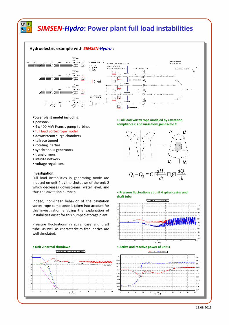
SIMSEN-Hydro: Power plant full load instabilities
Hydroelectric example with SIMSEN-Hydro :
Power plant model including:
• penstock
• 4 x 400 MW Francis pump-turbines
• full load vortex rope model
• downstream surge chambers
• tailrace tunnel
• rotating inertias
• synchronous generators
• transformers
• infinite network
• voltage regulators
• Full load vortex rope modeled by cavitation
compliance C and mass flow gain factor C
2 21 2
dH dQQ Q C
dt dtχ− = ⋅ + ⋅Investigation:
Full load instabilities in generating mode are
induced on unit 4 by the shutdown of the unit 2
which decreases downstream water level, and
thus the cavitation number.
Indeed, non-linear behavior of the cavitation
vortex rope compliance is taken into account for
this investigation enabling the explanation of
instabilities onset for this pumped-storage plant.
Pressure fluctuations in spiral case and draft
tube, as well as characteristics frequencies are
well simulated.
• Pressure fluctuations at unit 4 spiral casing and
draft tube
• Active and reactive power of unit 4• Unit 2 normal shutdown

13.08.2013
SIMSEN-Hydro: Pumped-Storage Plant
Hydraulic transient of complex pumped-storage plant with SIMSEN-Hydro :
Power plant model
including:
• 2 reservoirs
• 2 galleries
• 2 surge chambers
• 2 penstocks
• 3 x 25 MW Pelton Units
• 1 x 25 MW pump
• 1 x Siphon pump
Investigation:
The pumped-storage power plant comprises 3 units:
- Unit 1: with Pelton turbine and siphon driven by the
same synchronous generator all on the same shaft
line;
- Unit 2: with Pelton turbine and storage pump driven
by the same generator on the same shaft line;
- Unit 3: with Pelton turbine only.
There is more than 60 different operating
configurations.
Thus, complex emergency
shutdown procedures in
turbine and pump modes are
simulated to define
maximum power plant
solicitations.
Discharge pump [m3/s]
Discharge siphon pump [m3/s]
Total discharge [m3/s]
Discharge Pelton unit 2 [m3/s]
Head in penstock (2nd) [mWC]
• Discharge in Pelton turbine and Pump of
Unit 2 and Siphon pump during pump
emergency shutdown with Pelton nozzle
openings to avoid reverse pumping
• Penstock head for different
reservoir water level settings
resulting from 3 units emergency
shutdown

13.08.2013
SIMSEN-Hydro: Hydraulic test rig resonance
Example of Validation of SIMSEN-Hydro :
Modelling of Francis turbine scaled model test
rig with SIMSEN-Hydro to explain vortex rope
induced resonance of the hydraulic circuit.
The closed loop test rig model includes the
model of the downstream tank, the parallel
pumps, the piping system, the turbine and the
draft tube.
The draft tube model is modeled with 2 pipes
and a pressure source. Free and forced
oscillations are preformed.
• Free oscillation analysis: based on PRBS
excitation (PRBS: Pseudo Random binary
Sequence)
• Water fall diagram of the pressure pulsations
resulting from free oscillation analysis
• Forced response analysis: Pressure source
excitation modeling vortex rope excitation
• Water fall diagram of the pressure pulsations
resulting from forced oscillation analysis
• Comparison of pressure amplitude spectra at pressure source and turbine cone in the case of forced response
analysis showing good agreements for the characteristic frequencies

13.08.2013
SIMSEN-Hydro: Transient of Variable Speed
Pump-Turbine Unit
Transient of variable speed pump-turbine with SIMSEN-Hydro :
• 2x320MW Variable Speed Pump-Turbine Power Plant
A 2x320 MW Pumped-Storage plant is
modeled with SIMSEN and includes:
- Hydraulic circuit
- Pump-turbine
- Doubly Fed Induction Generator
(DFIG) with 3 levels Voltage
Source Inverter (VSI)
- Infinite power network
Variable speed advantages:
- Possibility of active power control
in pumping mode
- Efficiency increase and wide
range of operation in generating
mode especially under partial
load
- Network stability improvement
by reactive power control
- Network stability improvement
by instantaneous power injection
in the grid « Flywheel Effect»
- Starting of the group in pumping
mode without supplementary
equipment
• Control strategy in turbine mode of operation
Turbine mode Pumping mode
Fa
st a
ctiv
e p
ow
er
ad
just
me
nt
Pu
mp
-tu
rbin
e
tra
nsi
en
t
• Turbine speed governor
• Variable speed unit transient resulting from power setpoint change

13.08.2013
SIMSEN-Hydro: Pumped-Storage Plant
in Mixed Islanded Power Network
Modeling of mixed islanded power network with SIMSEN-Hydro :
A mixed islanded power network is
modeled with SIMSEN and includes:
- 2x250 MW Pumped-Storage plant
- 100x2 MW = 200 MW Wind Farm
- 1300 MW Thermal Power Plant
- Passive consumer load.
Pumped-Storage Plant model
The Pumped-storage plant is made of:
- upstream reservoir;
- gallery;
- penstock;
- 3 type-machine unit with
Francis turbine, generator, fluid
coupling and pump on the
same shaft line (3 inertias model);
- tailrace water tunnel;
Thermal Power Plant model
The thermal power plant model
includes:
- upstream steam pressurized
tank;
- high pressure steam turbine;
- re-heater;
- 2 low pressure steam turbines;
- and a 4 inertias shaft line.
Wind Farm model
The Wind farm model is a 100x2 MW
equivalent wind turbine model,
comprising:
- wind model;
- shaft line model with shaft
stiffness, turbine and generator
inertias and gearbox ratio;
- the wind turbine energy
transfer is modeled with
a power coefficient Cp
as function of the tip
speed ratio and blade
pitch angle.
• Pumped-Storage
plant 2x250 MW with 3
type-machine
arrangement
• Thermal power plant 1300 MW
• 100 Wind turbines 2MW

13.08.2013
SIMSEN-Hydro: Pumped-Storage Plant
in Mixed Islanded Power Network
Transient of mixed islanded power network with SIMSEN-Hydro :
The 3 type machine unit enables:
- adjustable pump power by hydraulic
short-circuit operation;
- rapid pump to turbine operating
mode change-over because of same
rotating direction of the pump and
the turbine.
The pump to turbine change-over
operation is simulated considering a wind
farm shutdown due to wind over speed.
The wind farm power loss is compensated
by the pumped-storage plant.
• The wind turbine power is given by:
0 4 8 12 16 20Tip Speed Ratio: λ = Ut/Cinf [-]
0
0.2
0.4
Cp [
-]
0°1°2°5°10°15°20°25°35°50°
3inf
1
2P Aref Cp Cρ= ⋅ ⋅ ⋅
21/116( , ) 0.5 0.4 5 i
i
Cp e λλ θ θλ
− = − − ⋅
3
11 0.0350.08 1
iλ
λ θ θ
=−
+ +
1
inf inf2reft
DU
C C
ωλ
⋅= =
⋅
• with the empirical expression of the power
coefficient:
• and with the tip speed ratio:
• and the parameter:
• Wind turbine transient during emergency
shutdown due to over-speed wind (first,
aerodynamic brake with stall control and then
circuit beaker tripping):
• Pump shutdown for operating mode change over
with clutch decoupling:
• Turbine transient with speed regulator to
compensate Wind Farm power loss:
• Power generation during the transient:
13.08.2013
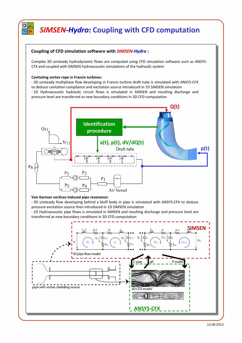
SIMSEN-Hydro: Coupling with CFD computation
Coupling of CFD simulation software with SIMSEN-Hydro :
Complex 3D unsteady hydrodynamic flows are computed using CFD simulation software such as ANSYS-
CFX and coupled with SIMSEN hydroacoustic simulations of the hydraulic system
Identification
procedure
Q(t)
p(t)a(t), p(t), dV/dQ(t)
SIMSEN
ANSYS-CFX
Cavitating vortex rope in Francis turbines:
- 3D unsteady multiphase flow developing in Francis turbine draft tube is simulated with ANSYS-CFX
to deduce cavitation compliance and excitation source introduced in 1D SIMSEN simulation
- 1D Hydroacoustic hydraulic circuit flows is simulated in SIMSEN and resulting discharge and
pressure level are transferred as new boundary conditions in 3D CFD computation
Von Karman vortices induced pipe resonance:
- 3D unsteady flow developing behind a bluff body in pipe is simulated with ANSYS-CFX to deduce
pressure excitation source then introduced in 1D SIMSEN simulation
- 1D Hydroacoustic pipe flows is simulated in SIMSEN and resulting discharge and pressure level are
transferred as new boundary conditions in 3D CFD computation

13.08.2013
SIMSEN Users and Partners
Ecole Polytechnique Fédérale de Lausanne
CH-1015 Lausanne
Switzerland
http://simsen.epfl.ch
Power Vision Engineering Sàrl
Ch. Des Champs-Courbes 1
CH-1024 Ecublens
Switzerland
http://www.powervision-eng.ch
Demo version available on:
http://simsen.epfl.ch
SIMSEN Contacts
HIDROINŠTITUT
For distribution, support and trainings:


