Embed Size (px)
Citation preview
18th International Conference on Renewable Energies and Power Quality (ICREPQ’20) Granada (Spain), 1st to 2nd April 2020
Renewable Energy and Power Quality Journal (RE&PQJ)
ISSN 2172-038 X, Volume No.18, June 2020
Simulation Technologies Applicable to Microgrids R. B. Otto1, F. P. Silva¹, M. B. do Carmo¹, A. B. Piardi1 and R. A. Ramos2
1 LASSE - Itaipu Technological Park
Foz do Iguaçu, Paraná (Brazil)
Phone/Fax number: +5545 35767089, e-mail: [email protected], [email protected]
2 EESC - University of Sao Paulo
São Carlos, São Paulo (Brazil)
Abstract. The new paradigm of the electric sector, given the
increased penetration of distributed generation, includes a
growing number of microgrids. Therefore, the implementation of
microgrids needs to be preceded by studies and simulations to
evaluate the possible scenarios under which these systems will
operate. This paper presents an overview of state-of-the-art
technologies for microgrid simulation and describes an example
implemented at the facility to which the first authors are
affiliated.
Key words. Microgrid, Simulation Tools, Real-Time
Simulation, Distributed Energy Resources, Hardware-in-
the-Loop.
1. Introduction
The deregulation process of electrical power systems – that
opened the way towards competitive markets with
independent power producers – added to the necessities
demanded by industrialized economies characterized by
the diversification of energy matrix as well as the
increasing of the efficiency in the process of generation
and transport of electric power, provided the subsidies for
the advent of distributed generation concept.
To take advantage of the potential benefits from in
distributed generation, there is a necessity for a complete
overhaul of electricity distribution systems through better
use and complete automation of their elements, giving rise
to the concept of microgrids [2] [3]. For the fact that these
systems can be considered a basic feature of future
distribution systems, and due to its inherent operation
complexity, it becomes mandatory to characterize their
behavior and performance, both in the design phase as well
as during their operation.
In the context previously presented, in this paper, a brief
contextualization of microgrids will be presented, followed
by a review of the technologies applicable to the
simulation and testing of microgrids. To validate the
proposal a microgrid model commonly referenced in the
technical literature was modeled on a real-time simulation
platform.
2. Microgrids
Microgrids are defined as distributed electrical systems
containing loads and distributed energy resources - DER
(such as distributed generators, energy storage systems
and controllable loads) that can be operated in a
controlled and coordinated manner, connected to or
isolated from the main network [4].
The main reason for using a microgrid is to incorporate
the full potential of distributed generation sources into
the electrical system [1] [6], using these resources
intelligently and efficiently.
Figure 1 presents the general architecture of a microgrid,
which can be divided into three main layers, reflecting
the challenges for microgrids implementation [2] [3] [4]:
1. First layer – constituted by the power equipment
(electrical system). The main challenges of this
layer are: Integration and operation of DER;
2. Second layer – constituted by the
communication infrastructure. The main
challenges of this layer are: Integration of
equipment with different protocols, availability,
reliability, scalability and cybersecurity;
3. Third layer: constituted by the high-level control
system, which contains the general controllers
and Human-Machine Interfaces (HMIs). The
main challenges of this layer are: Optimization
and Coordination of DER.
Figure 1 - The general architecture of a microgrid [5]
https://doi.org/10.24084/repqj18.439 584 RE&PQJ, Volume No.18, June 2020

According to [7], we have advantages in the use of
microgrids from the economic, technical and
environmental point of view.
I. Economic: the possibilities of profit due to power
generation by the owners of distributed
generation sources, the creation of new business
models for the distribution concessionaires, and
the increased efficiency in the processes of
generation and consumption of electrical energy.
II. Environmental: reduction of greenhouse gases by
promoting the use of renewable energy sources.
III. Technical: relief of the main system overload,
support in the frequency and voltage regulation,
reduction of losses and the increase of reliability
of the power supply to end consumers.
Because microgrids are considered a reality for future
power systems, in addition to their inherent operation
complexity, it is mandatory to characterize their behaviors
and performances, both in design and operation phases [7].
In this context, computer simulations favor the analysis
and verification of many concepts and schemes related to
microgrids [8].
3. Simulation Tools
There are several tools for simulation and analysis of
microgrid. The use of computer simulators, tools that
allow the study and testing of various microgrids
architectures and operational scenarios, make it easier to
understand the phenomena and concepts surrounding these
systems [9].
GridLAB-D is an open-source software. It was developed
by the US Department of Energy (DOE) through Pacific
Northwest National Laboratory (PNNL). It is purely
command-line software (without Graphical User Interface
(GUI)), where the simulation is flexible and based on
agent modeling. The input files (.GLM and .XLM) are
processed and generate the simulation result in output
files. This allows large systems to be efficiently simulated.
This software can also be seen as a collection of modeled
objects that represent the various elements present in
distribution systems [11].
The company responsible for developing the Hybrid
Optimization Model for Multiple Energy Resources
(HOMER) was founded in 2009 by the National
Renewable Energy Laboratory (NREL). HOMER Energy
sells two products, HOMER PRO and HOMER GRID.
Both products do the technical optimization and find the
lowest cost system that meets technical restrictions
imposed by the application [12].
MATLAB is a proprietary software, which has MATLAB
Simulink as its simulation platform. Among the simulation
tools, MATLAB Simscape Electrical is the solution for the
simulation of electronic components, mechatronics, and
power systems. Usually, this tool is referred by the name
of SimPowerSystems, and many publications still referring
to this name [13].
Open Distribution System Simulator (OpenDSS) is an
open-source software for the simulation of power
distribution systems. Since 1997 it is maintained by
Electric Power Research Institute (EPRI), and its purpose
is to facilitate studies of DER interconnection in the
context of smart grids [14].
Power Systems Computer Aided Design (PSCAD) is a
tool for simulation of electromagnetic transients.
Developed in 1976, the program is a user-friendly
interface, widely recognized to perform electromagnetic
transient analyses. The visual environment provided by
PSCAD supports the interfaces of circuit modeling,
runtime control, analyses and report generation [17].
The increase and importance of microgrids have brought
a demand for study tools and sophisticated Hardware-in-
the-Loop (HIL) testing facilities to evaluate the operation
of associated control and power devices in the grid [10].
The great advantage of the Real-Time Simulator (RTS)
platforms is to allow the possibility to interface external
devices – usually referenced as Devices Under Test
(DUTs) [5], [15] ,[16]. Three real-time simulation
platforms were analyzed: OPAL-RT, Typhoon HIL, and
RTDS.
Founded in 1997, OPAL-RT Technologies is a Canadian
company that markets RTS to meet the demands of
industry and research institutes. The OPAL-RT
simulation platform uses two main software: HYPERSIM
and RT-LAB [18]. To better understand the differences
between simulation platforms, OPAL-RT provides a
comparative table in [20] and a catalog in [19]. In [20],
related information is provided in the above paragraphs
in a more organized manner, as well as specific
applications with each platform. In [19], a comparative
graph is presented between the four solutions based on
the frequency of the phenomena represented and the
number of nodes of the simulated system.
Founded in 2008, North American Typhoon HIL Inc.
sells three series of RTS platforms: 4, 6 and M. The
series 4, model HIL402, has the size of a notebook and
uses a software called HIL Control Center. Series 6 is
more focused on power electronics. With up to six cores,
the HIL602 weighs approximately 4kg. On the other
hand, Series M is specifically intended for testing
controllers and has several sizes. The software includes
the following modules: Schematic Editor, for modeling
the circuits; HIL SCADA, which allows the user to
reconfigure the testbed; Test Suite, which comprises a
certification program; and Power Systems Toolbox,
which comprises a library specially developed for
microgrid analyses [21].
Real-Time Digital Simulator (RTDS) refers to the RTS
platform produced by Canadian company RTDS
Technologies. The company was responsible for
introducing the first fully digital power system simulator
in 1989. As a result, RTDS has become a world reference
for the simulation of power systems in real-time. The
main applications are in the areas of: microgrid/smart
grid simulation, cyber-security, Power Hardware-in-the
https://doi.org/10.24084/repqj18.439 585 RE&PQJ, Volume No.18, June 2020
Loop (PHIL), High Voltage Direct Current (HVDC)
systems, Flexible Alternate Current Transmission Systems
(FACTS), protection systems testing, power electronics,
control systems testing, Phasor Measurement Units
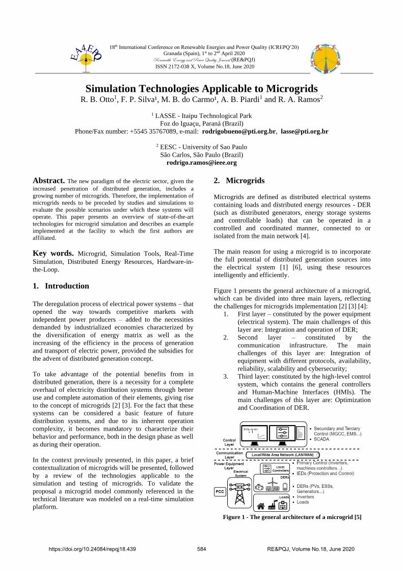
(PMUs) testing, IEC 61850, and DER integration. Figure 2
illustrates the application of RTDS simulator in microgrids
analyses, where is enabled the testing of physical
equipment in the same conditions encountered in real
applications [10]. To construct the models a proprietary
software package denominated Real-time Simulation
Computer Aided Design (RSCAD) is used. This software
package was developed to provide a fully graphical
interface to the RTDS, making easier the operation of the
real-time simulation platform.
Figure 2 - HIL testing of microgrid control systems using
RTDS [10]
Due to the potentialities pointed out, added to the
equipment availability at the Itaipu Technological Park
laboratorial infrastructure, the simulation tool used in this
article was the RTDS platform.
4. Example of Microgrid Implementation in
a RTS Platform
This section presents an actual implementation of a
benchmark microgrid model in a real-time simulator
performed at the facility to which the first authors of the
paper are affiliated. This implementation represents
entirely the microgrid through digital models in the
simulation environment, being feasible to exchange data
with peripheral equipment (such as controllers) via
communication protocols or analog interface, closing the
loop in the simulation [2].
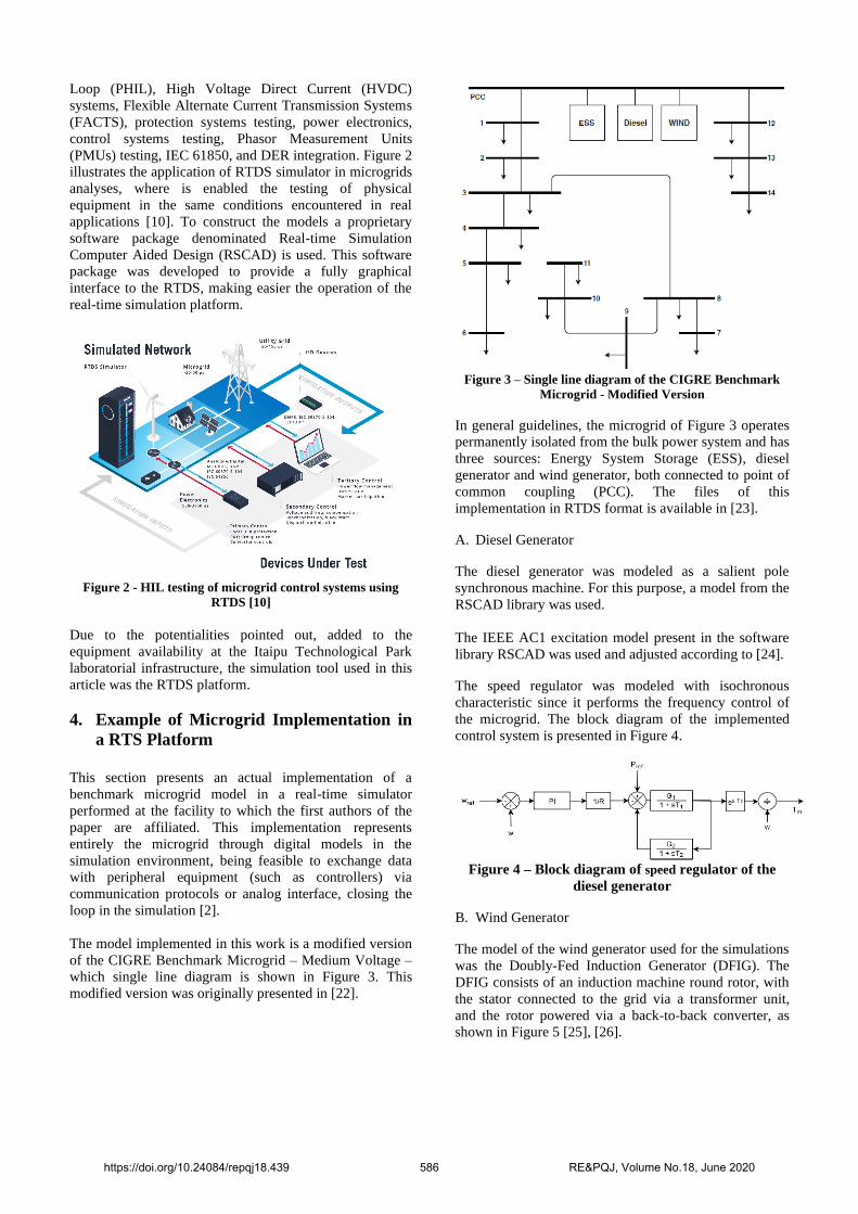
The model implemented in this work is a modified version
of the CIGRE Benchmark Microgrid – Medium Voltage –
which single line diagram is shown in Figure 3. This
modified version was originally presented in [22].
Figure 3 – Single line diagram of the CIGRE Benchmark
Microgrid - Modified Version
In general guidelines, the microgrid of Figure 3 operates
permanently isolated from the bulk power system and has
three sources: Energy System Storage (ESS), diesel
generator and wind generator, both connected to point of
common coupling (PCC). The files of this
implementation in RTDS format is available in [23].
A. Diesel Generator
The diesel generator was modeled as a salient pole
synchronous machine. For this purpose, a model from the
RSCAD library was used.
The IEEE AC1 excitation model present in the software
library RSCAD was used and adjusted according to [24].
The speed regulator was modeled with isochronous
characteristic since it performs the frequency control of
the microgrid. The block diagram of the implemented
control system is presented in Figure 4.
Figure 4 – Block diagram of speed regulator of the
diesel generator
B. Wind Generator
The model of the wind generator used for the simulations
was the Doubly-Fed Induction Generator (DFIG). The
DFIG consists of an induction machine round rotor, with
the stator connected to the grid via a transformer unit,
and the rotor powered via a back-to-back converter, as
shown in Figure 5 [25], [26].
https://doi.org/10.24084/repqj18.439 586 RE&PQJ, Volume No.18, June 2020

Figure 5 – Doubly-fed induction generator
The DFIG model has gained importance due to the
technological advances in the power electronics area, and
the development of vector control techniques. This
arrangement allows the decoupling between active and
reactive power, as well as the generation of power at rated
frequency and voltage regardless of the rotor speed [25],
[26].
The back-to-back converter controls the power flow
between the rotor and the grid. This converter consists of
two inverters with Insulated Gate Bipolar Transistors
(IGBTs), sharing a direct current link as illustrated in
Figure 6 [25], [26].
Figure 6 – Back-to-back converter circuit
In this work, the detailed back-to-back converter model
was implemented. In other words, the IGBTs keys were
properly represented as illustrated in Figure 6.
For proper operation of this converter two control systems
are required, namely the Rotor Side converter Controller
(RSC), and the Grid Side converter Controller (GSC). RSC
is responsible for control the active and reactive powers
provided by the wind generator, while GSC is responsible
for maintaining constant DC-link voltage, to provide
reactive power support, and to control the power exchange
between the grid and the converter. More information
about these controllers can be found in [25], [26].
C. Energy Storage System
The battery model used was the Li-Ion Battery technology
– which is present in the RSCAD library – connected to
the network via a Voltage Source Converter (VSC).
The VSC was implemented using an averaged model with
dependent sources, as illustrated in Figure 7. As it neglects
the effects of thyristor switching [27], the averaged model
was used due to the processing limitations of the real-time
simulation structure available for testing.
According to [27], although it is not a true representation
of the DC/AC converter, the model used does not show
significant losses when compared to the detailed model if
the microgrid operates under load and with balanced
conditions.
Figure 7 – Back-to-back converter circuit
The used battery control is based on the d-q axis
decoupling for the control of the active and reactive
power supplied to the grid. Figure 8 illustrates the block
diagram of the battery control.
Figure 8 – Block diagram of the battery control
D. Transmission Lines
Due to their small lengths, the transmission lines were modeled
using their PI equivalents. The electrical parameters of the lines
can be found in [22].
E. Loads
All loads of the microgrid are three-phase, balanced and
were modeled as dynamic loads. This model is available
in RSCAD software package. The electrical parameters of
the lines can be found in [22].
5. Tests and Results
In this section, the results obtained from the initial tests
performed in the implemented microgrid are shown. Due
to processing limitations, the global simulation time-step
was set to 90µs. Furthermore, it was adjusted a sub-time
step of 3.6µs to simulate the power electronics
converters.
In order to analyze the dynamic performance of the
system, three simulations of events held to test the
implemented microgrid, which will be described below.
In both simulations, the diesel generator supplied
approximately 0.2MW of active power and 0.3Mvar of
reactive power, the battery bank provided approximately
0.2MW of active power, and the wind generator
approximately 0.7MW of active power.
https://doi.org/10.24084/repqj18.439 587 RE&PQJ, Volume No.18, June 2020

Each simulation performed differs in the level of the load
step applied at Bus 9. The load step applied in each
simulation is presented in Table I.
Table I – Load steps for the simulated events
Simulation Active Power
[MW]
Reactive Power
[MVar]
1 0.34 0.036
2 0.5 0.051
3 0.5 0.51
Also, it was considered that there is an extremely
important load connected to bus 11, so this bus was
considered the main bar of the system.
Figure 9 shows the results of frequency and voltage at bus
11 for the simulated events. It is verified that the microgrid
is stable from the viewpoint of simulated events, and the
electrical quantities reach adequate values after the
perturbations. It is important to highlight that the results
presented in Figure 9 can be externalized to test the
equipment present in the control center (third layer) to
define and validate the best control strategy.
Figure 9 – System frequency and voltage at bus 11 for
the simulated events
5. Conclusion
Because it is a multidisciplinary and highly complex
theme, the complete understanding of the phenomena that
permeate the concept of microgrids demands the
application of sophisticated analysis tools. Within this
context, this paper presented a comprehensive survey of
the main tools used for this task.
Among the presented tools, emphasis is given to those
involving the concept of HIL simulation. Through the use
of real-time simulation platforms and by establishing
appropriate interfaces between simulated and real parts of
the system, the HIL concept allows equipment to be tested
in conditions very close to those found field, with the
advantage of analysis flexibility through the possibility of
representation of different operational conditions.
The results from the presented example, which correspond
to an actual implementation at the facility to which the first
authors are affiliated, illustrated the previously mentioned
advantages of having a flexible testbed for microgrid
simulation.
Acknowledgement
We are grateful for the support of Itaipu Binacional and
Itaipu Technological Park. This work is part of the
research group "Microgrids and Systems with Distributed
Generation by Real Time Simulation" (CNPQ) and
"Hybrid Intelligent Electrical Microregions with High
Penetration of Renewable Energies" (CYTED-
717RT0533).
References
[1] R. H. Lasseter, “Microgrids”. IEEE Power
Engineering Society Winter Meeting. (2002.) v. 1, p.
305–308 vol.1..
[2] A. B. Piardi, R. B. Otto , D. G. Sonoda, F. C. Santos,
L.R.A Ferreira and R. A. Ramos, “Laboratory for
Analysis of Microgrid with Real Time Simulation”,
ICREPQ’19 (2019).
[3] Working Group C6.22 “Microgrids Evolution
Roadmap, Microgrids 1 Engineering, Economics, &
Experience” CIGRE (2015).
[4] A. Bani-Ahmed and A. Nasiri, "Development of
Real-Time Hardware-in-the-Loop Platform for Complex
Microgrids," ICRERA (2015), Palermo, pp. 994-998.
[5] A. B. Piardi, F. C. dos Santos, D. G. Sonoda, R. B.
Otto, “Aspects of a Hybrid and Flexible Microgrid
Laboratory Implementation”, XIV SEPOPE (2018).
[6] Marnay, C. et al. “Microgrid evolution roadmap”.
EDST (2015). p. 139–144.
[7] N. Hatziargyriou, et al. “Microgrids”. IEEE Power
and Energy Magazine (2007). v. 5, n. 4, p. 78–94.
[8] B. Xiao, et al. “Development of hardware-in-the-loop
microgrid testbed”. IEEE Energy Conversion Congress
and Exposition (2015).
[9] P. P. Domingues, et Al. “Uso de Software Livre em
Atividades de Ensino e Pesquisa em Microeletrônica”.
XLIV COBENGE (2016).
[10] RTDS Technologies, “Microgrid Simulation and
Testing”. Available in: < https://www.rtds.com/ >.
Access in 2019.11.11.
[11] D. P. Chassin, K. Scheneider, C. Gerkensmeyer.
“Gridlab-D: An opensource power systems modeling and
simulation environment”. T&D (2008). p. 1–5. ISSN
2160-8555.
[12] HOMER. HOMER PRO and HOMER GRID. 2019.
Available in: < https://www.homerenergy.com >. Access
in 2019.11.11
[13] MATLAB Simscape Electrical. 2019. Available in:
<
https://www.mathworks.com/products/simscapeelectrical
.html >. Access in 2019.11.11
[14] EPRI. “Introduction to the OpenDSS”. (2009).
Available in: <http:// https://www.epri.com/#/pages/sa/opendss?lang=en-US/>.
Access in: 2019.11.11
[15] W. Ren, M. Steurer and T. L. Baldwin, "Improve the
Stability and the Accuracy of Power Hardware-in-the-
Loop Simulation by Selecting Appropriate Interface
https://doi.org/10.24084/repqj18.439 588 RE&PQJ, Volume No.18, June 2020

Algorithms," in IEEE Transactions on Industry
Applications, vol. 44, no. 4, pp. 1286-1294, July-Aug.
2008.
[16] J. Wang, Y. Song, W. Li, J. Guo and A. Monti,
"Development of a Universal Platform for Hardware In-
the-Loop Testing of Microgrids," in IEEE Transactions on
Industrial Informatics, vol. 10, no. 4, pp. 2154-2165, Nov.
2014.
[17] PSCAD. “User´s Guide on the use of PSCAD”
(2018). Available in: <https://hvdc.ca/uploads/knowledge
base/pscad manual v4 6.pdf?t=1528395602>. Access in:
2019.11.13
[18] OPAL-RT. “Simulator Platform Comparison Chart”
(2019). Available in:
<https://www.opalrt.com/wpcontent/themes/ enfold-
opal/pdf/L00161 0472.pdf>. Access in: 2019.11.13
[19] OPAL-BROCHURE. “Real-Time Simulation
Solutions for Power Grids and Power Electronics” (2019).
Available in: <https://www.opal-
rt.com/wpcontent/themes/enfoldopal/pdf/
L001610260.pdf>. Access in: 2019.11.13
[20] OPAL-CHART. “Website da OPAL-RT” (2019).
Available in: <https://www.opal-rt.com/>. Access in:
2019.11.13
[21] TYPHOON. Website da Typhoon HIL. 2019.
Available in: <https://www.typhoon-hil.com/>. Access in:
2019.11.13
[22] CIGRE Task Force C6.04.02, Benchmark Systems for
Network Integration of Renewable and Distributed Energy
Resources. CIGRE, (2014).
[23] R. B. Otto, R. F. Espinoza, A. Piardi, and M. do
Carmo. “Microgrid benchmark system: Rtds
implementation,”. Available in:
<https://github.com/Itaipr/MICROGRID-RTDS> (2019)
[24] “IEEE recommended practice for excitation system
models for power system stability studies,” IEEE Std
421.5-2016 (Revision of Std 421.5-2005), pp. 1–207, Aug
2016.
[25] G. Abad, J. Lopez, M. Rodriguez, L. Marroyo, and G.
Iwanski, Doubly fed induction machine: modeling and
control for wind energy generation.
[26] H. Abu-Rub, M. Malinowski, and K. Al-Haddad,
Power electronics for renewable energy systems,
transportation and industrial applications.
[27] M. Farrokhabadi, S. Konig, C. A. Canizares, K.
Bhattacharya, and T. Leibfried, “Battery energy storage
system models for microgrid stability analysis and
dynamic simulation,” IEEE Transactions on Power
Systems, vol. 33, no. 2, pp. 2301–2312, March 2018.
https://doi.org/10.24084/repqj18.439 589 RE&PQJ, Volume No.18, June 2020


![Coordination Control Strategy for AC/DC Hybrid Microgrids in ......AC and DC microgrids is proposed, and this emerges the concept of hybrid AC/DC microgrids [5,6]. Control of microgrids](https://img.dokumen.tips/doc/110x75/61032ae7c5c5ba536268cbac/coordination-control-strategy-for-acdc-hybrid-microgrids-in-ac-and-dc-microgrids.jpg)