Embed Size (px)
Citation preview

HAL Id: hal-00926701https://hal.archives-ouvertes.fr/hal-00926701v2
Submitted on 21 Feb 2014
HAL is a multi-disciplinary open accessarchive for the deposit and dissemination of sci-entific research documents, whether they are pub-lished or not. The documents may come fromteaching and research institutions in France orabroad, or from public or private research centers.
L’archive ouverte pluridisciplinaire HAL, estdestinée au dépôt et à la diffusion de documentsscientifiques de niveau recherche, publiés ou non,émanant des établissements d’enseignement et derecherche français ou étrangers, des laboratoirespublics ou privés.
Simulation study of a heat pump for simultaneousheating and cooling coupled to buildings
Redouane Ghoubali, Paul Byrne, Jacques Miriel, Frederic Bazantay
To cite this version:Redouane Ghoubali, Paul Byrne, Jacques Miriel, Frederic Bazantay. Simulation study of a heat pumpfor simultaneous heating and cooling coupled to buildings. Energy and Buildings, Elsevier, 2014, 72,pp.141-149. <10.1016/j.enbuild.2013.12.047>. <hal-00926701v2>

Simulation study of a heat pump for simultaneous heating and
cooling coupled to buildings
Redouane GHOUBALI(a)(b), Paul BYRNE(a)*, Jacques MIRIEL(a), Frédéric BAZANTAY(b)
(a) Université Européenne de Bretagne
Université de Rennes1, Laboratoire LGCGM, Equipe MTRhéo
IUT Génie Civil, 3 rue du Clos Courtel, BP 90422, 35704 Rennes Cedex 7, France
Phone: +33 2 23 23 42 97 - Fax: +33 2 23 23 40 51
(b) Pôle Cristal
48, Promenade de la Fontaine des Eaux
BP 56357
22106 DINAN Cedex
* corresponding author: [email protected]

ABSTRACT
In several situations, a heat pump for simultaneous heating and cooling (HPS) can be installed advantageously in
buildings where simultaneous needs occur. Unlike a reversible heat pump that works alternatively in heating or
cooling, a HPS operates under three modes: a heating mode, a cooling mode and a simultaneous mode.
In this article, different types of buildings are simulated using Trnsys software to identify their needs for heating,
cooling and domestic hot water production (DHW). The introduction of a ratio of simultaneous needs in heating
and cooling (RSN) can qualify buildings in relation to the appropriateness of a HPS. Three kinds of buildings are
investigated (a low-energy building, an office building and a retail space) under three different climatic conditions
in France.
As the design of a heat pump is highly dependent on the refrigerant properties, models of small-to-medium HPS
using R407C, R290 and HFO1234yf are developed. Results of experimental tests on a 15 kW-heating-capacity
HPS working with R407C were used to validate the numerical models of components and global model. Finally, a
co-solving technique using two environments (EES and Trnsys) is used to compare the performance of the
different refrigerants coupled to the building having the best RSN.
Keywords: heat pump, heating, cooling, domestic hot water, simultaneous production, simultaneous needs

1. INTRODUCTION
The evolution of thermal regulations leads to the improvement of the thermal envelope of buildings. It has greatly
contributed to the decrease of heating needs of constructions. In parallel, the use of increased surface areas of
glazed surfaces and the increase of heat gains by electrical equipment and by a dense occupation induce a
significant increase in air conditioning needs. The latest studies on low-energy buildings in France indicate that
the production of domestic hot water (DHW) is to become the first sector of energy consumption. In this context,
the recommendations of the International Energy Agency in the "technology roadmap" in 2050 [1] advocate the
development of systems able to produce domestic hot water, heating and cooling at the same time. The weight of
simultaneous needs in heating, cooling and domestic hot water is a decisive factor in the choice of a technical
solution. Thus, a heat pump for simultaneous heating and cooling (HPS), producing at the same time hot and
chilled water, seems an interesting solution.
Some studies were carried out previously in that field. Lecrivain [2] highlights the performance of a HPS that
produces hot water at 95 °C and chilled water. The machine consists of two refrigerant circuits in cascade using
R22 as refrigerant in a low-temperature cycle and R114 in a high-temperature cycle. This solution has saved 36
tons of oil equivalent (toe, primary energy) compared to a natural gas boiler and cooling unit solution. Ghosh [3]
has quantified the economic benefits of a HPS in the industry. They found that for the cost of electricity in India, a
heat pump with simultaneous production has a payback time less than 18 months. An air handling unit with
simultaneous production of domestic hot water is presented by Gong [4]. A prototype of 7 kW cooling capacity
has been achieved. The prototype was tested in different climates and the coefficient of performance achieved is
equal to 6. Fatouh [5] has developed a prototype of water to water heat pump using R134a as refrigerant. The
latter can operate in heating, cooling or simultaneous mode. The coefficient of performance in simultaneous mode
is defined as the ratio of the sum of useful energy production over electrical power consumption. Other studies
dealing with heat pumps for simultaneous heating and cooling were carried out and give interesting results in
terms of performance [6-8]. Based on this review, these heat pumps are interesting solutions to heat, cool and
even produce domestic hot water. In addition, the control strategy appears to be a key point to optimize the heat
pump performance and to adapt thermal productions to the needs of the users and to the nature of the building.

The applications are numerous: air-conditioning, refrigeration, space heating, domestic water heating for
residential and office buildings, dairies… In this article, different types of buildings are considered and simulated
using Trnsys software to identify the needs of buildings. A co-solving technique using two environments (EES
and Trnsys) is used to accomplish the three following objectives:
- the choice of a market target by the evaluation of the appropriateness of different types of building to the
HPS,
- the choice of a refrigerant by comparison of the performance of different refrigerants coupled to the
building with the most simultaneous needs,
- the assessment of the seasonal coefficient of performance depending on the strategy regarding domestic
hot water production.
2. SIMULTANEOUS NEEDS
2.1. Needs of buildings in heating and cooling
The potential of the HPS depends heavily on the existence of simultaneous needs in heating and cooling. Three
kinds of buildings are considered: a low-energy building, an office building and a retail store. The corresponding
major configurations of simultaneous needs in heating and cooling were then identified as follows. Case (a) – in
highly insulated residential buildings: cooling is needed to address the problem of overheating and DHW needs
also exist. Case (b) – in highly-glazed office buildings: other needs may appear simultaneously with facades
receiving less solar gains than others. In addition, solutions of “cloud computing” or server rooms in remote office
towers require large cooling needs throughout the year and heating needs during winter in other areas. Case (c) –
in retail stores: some stores require space heating and food cooling systems. The three buildings were modeled
using the 3D module of Trnsys. Parallelepipeds were placed in front of the windows to correspond to remote
masks shading solar radiation.
Table 1 presents the characteristics of the simulated buildings with occupation scenarios and assumptions on
lighting and electrical equipment. The floor areas were estimated to obtain thermal heating and cooling powers
that fit to the heating and cooling capacity of the HPS. The number of zones depends on the use and the

orientation of each room. The internal gains were simulated assuming that the total heat gain was a multiple of
pieces of equipment having the power of a standard personal computer (230 W).
The different types of buildings are simulated using Trnsys (TYPE 56) to identify the needs for space heating,
space cooling and DHW. The weather data files of three cities (Rennes, Marseille and Strasbourg) are used. The
needs for domestic hot water are given in kWh following equation 1 derived from a specification sheet [9].
)T(TV1.163q cwDHWDHWDHW (1)
The domestic hot water consumptions are the following.
- Retail store: 10 litres per day and per person at 45 °C [10]
- Office building: 5 litres per day and per employee at 60 °C [9]
- Low-energy residential building: 40 litres per day and per resident at 60 °C [10]
2.2. Ratio of simultaneous heating and cooling needs
A ratio of simultaneous needs in heating and cooling (RSN) can qualify buildings in relation to the
appropriateness of a technological solution for simultaneous production (equation 2). This ratio is defined as the
minimum of the ratio between the heating needs (sum of space heating and domestic hot water) and the cooling
needs during a day and the inverse value of this ratio. Thermal needs are evaluated by means of simulations using
Trnsys software. An integration time base of one day was chosen considering that the thermal storage tanks are
sized to contain the amount of heat necessary for one day of operation. This assumption enables to take into
account more simultaneous needs than when looking at hourly needs and to increase the use of the more favorable
simultaneous mode. Some previous simulations taught us that if the integration time is taken shorter, meaning that
one uses smaller thermal storage tanks or even no storage, the RSN decreases drastically. In addition, well sized
storage tanks are required for this type of heat pump for simultaneous heating and cooling.
h 24c
h 24DHWh
h 24DHWh
h 24c
q
qq,
qminRSN (2)
The average ratio of simultaneous needs over the year allows us to identify buildings that require more

simultaneous production over a year with:
- RSN = 0 % corresponds to no simultaneous needs,
- RSN = 100 % corresponds to simultaneous needs in heating and cooling throughout the year.
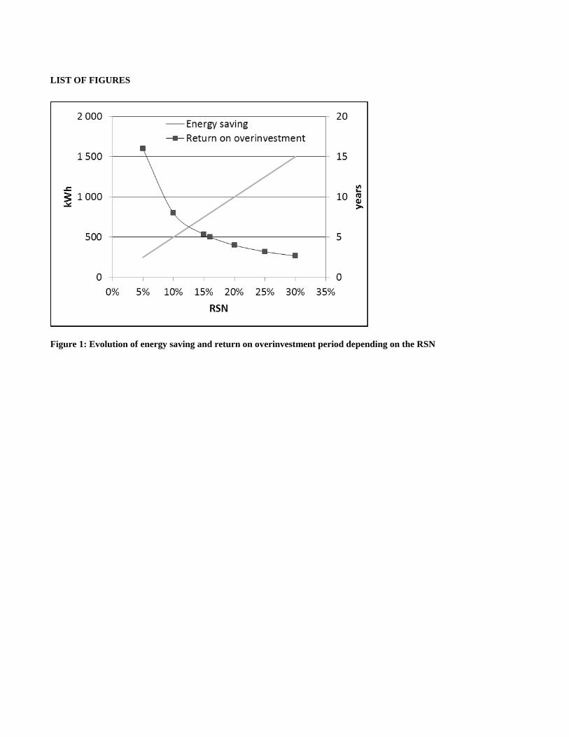
Recommended values of RSN can be addressed by the following gross approximation. The material cost
difference between a reversible heat pump and a HPS only really relies in the presence of an extra water
evaporator or condenser (plus its connections) to operate the heat pump in a simultaneous mode. The number of
electronic valves, expanders or non-return valves is roughly the same. It requires more development of the control
program but the impact on the cost of the machine is difficult to evaluate. The overinvestment is estimated at 400
€ for an extra heat exchanger of 11 kW in nominal conditions. The price of electric energy is approximately 0.1
€/kWh in France and kept constant. The annual thermal needs of a low-energy residential building are estimated
at 25000 kWh in heating and 5000 kWh in cooling. The annual heat pump performance in terms of both COP and
EER is equal to 3. Figure 1 shows the energy saving and the return on overinvestment period depending on the
RSN value. In this case, a return on overinvestment period of 5 years can be obtained with an RSN value of 16 %.
2.3. Analysis of thermal needs
The simulation results of daily RSN for a low-energy residential building, an office building and a retail space are
presented in figures 2, 3 and 4 respectively. The first simulations use weather data files of typical years of the city
of Rennes (France).
In the case of the residential building, DHW needs represent an important part of heating needs. Indeed this
building follows the latest French thermal regulation RT2012 in which one of the requirements is an average
primary energy consumption limit of 50 kWh per square meter and per annum including space heating and
cooling, DHW production, lighting, ventilation and auxiliaries. DHW accounts for around 25 kWh and space
heating and cooling, for around 15 kWh. The other 10 kWh are divided in the three other sectors of consumption.
The level of thermal insulation of low-energy buildings is so important that heat brought by solar radiation and
internal gains during spring, summer and autumn is hardly evacuated. A cooling device could thus be necessary to
avoid uncomfortable situations like the simulation results show. The RSN values become interesting during
summer when DHW and cooling needs appear simultaneously.

RSN values are very low during summer for the two other buildings because of low DHW needs compared to
cooling needs. High cooling needs during this period of the year are due to high solar radiation and internal heat
gains by Joule effect of electrical equipment. The ratio of simultaneous needs is very low during summer in the
case of offices and retail store. This is due to high demand for cooling because of high internal gains and low
domestic hot water needs. Out of this season, in the case of offices high RSN values are obtained thanks to
concomitant demands of cooling in some rooms with high internal gains and space heating of the north-oriented
part of the building.
Table 2 summarizes the average ratio of simultaneous needs for the residential low-energy building, the office
building and the retail store for oceanic, Mediterranean and continental climates. In general, the RSN is very low
during summer in the case of offices and retail space. This is due to important cooling needs because of high
internal gains and low domestic hot water needs. Indeed, improving the insulation of the building leads to a
phenomenon of overheating in summer. In addition, the needs for domestic hot water that certainly decrease in
summer (cold water is warmer) remain relatively high throughout the year.
The average annual ratio of simultaneous needs (RSN) is greater in the case of the office building (high cooling
needs) and residential building (high needs of domestic hot water) for different climates. We note that the RSN is
higher in the case of the residential building with a climate of Marseille because of higher cooling needs during
summer. In addition, the retail store records the lowest RSN due to the low use of domestic hot water.
The next step is to study the coupling of the HPS and buildings. Providing close and high values of RSN, the
residential low-energy building and the office building with the climate of Rennes are selected. The ratio of
simultaneous needs is very close between office buildings and low-energy residential buildings. The retail store
does not appear interesting because of low needs in heating during an important part of the year.
3. HPS MODEL
3.1. R407C HPS model
Semi-empirical models of the components involved in each mode are presented in this section. These semi-
empirical models are not directly transferable to other components and are limited to this HPS model. Changing

the flow rate of water, of air or the heat exchange surface for possible parametric study will require a reassessment
of the coefficients or the use of correlations validated by experimental tests. However they remain inspired of
previously published heat pump models or component models [11-13].
Unlike a reversible heat pump that works in either heating or cooling, the HPS has the particularity to operate
under three modes:
- a heating mode: corresponding to a classic air-source heat pump operation with an air evaporator and a
water condenser,
- a cooling mode: corresponding to a chiller operation with a water evaporator and an air condenser,
- a simultaneous mode: producing hot and chilled water simultaneously with water heat exchangers.
An experimental prototype was developed during a first thesis (figure 5) entitled "Experimental study and
simulation of a small to medium HPS" [14-17]. The water evaporator and the condenser are connected to two
300-litre tanks, respectively cold and hot water tanks. The DHW water tank was not installed in this first study.
Condensation and evaporation on air are carried out on the same air coil alternatively. The heat exchangers are
involved by opening the appropriate electronic valves depending on the selected operating mode.
3.2. Compressor model
The compressor model calculates the refrigerant mass flow rate, the electric power and the discharge temperature.
This model has as input data high and low pressures and temperature at suction. The mass flow rate is calculated
using the density at the suction of the compressor, the volumetric efficiency and the swept volume (equation 3).
The temperature at the compressor discharge found experimentally determined that isentropic and volumetric
efficiencies are functions of the compression ratio σ and superheating at the evaporator inlet. Equations 4 and 5
curve fits of experimental data. Thermodynamic work is given by equations 6 and 7. Points 1 and 2 correspond to
the inlet and the outlet of the compressor. The real power absorbed is determined from a compression efficiency
ηcomp established using experimental results (equations 8 and 9).
svol
.
r Vηρm (3)
0.59-SH0.0011+1.572+0.629-0.1092+-0.00703 234
is (4)

)1
1
((1 0.02)+0.004+2-0.0003vol
(5)
.
.
th
isis
W
W (6)
12is
.
r
.
is hhmW (7)
(8)
real.
W
thW
compη
(9)
3.3. Heat exchanger models
Models of heat exchangers use the logarithmic mean temperature difference as a calculation method. Heat
exchangers consist of a single zone to improve the convergence of calculations. This modeling assumption seems
simplified but however enables to obtain simulation results in terms of COP and EER in an acceptable uncertainty
range presented in the “validation and results” section. Thermal capacity exchanged in a counter-flow heat
exchanger can be written according to equations 10 to 13.
(10)
(11)
(12)
(13)
In the case of the air cross-flow heat exchanger a correction factor F is taken into account. Solving the system of
equations consisting of equations 10 to 13 allows obtaining the pressure (high pressure in the case of condenser

and low pressure in the case of the evaporator) and the temperatures at the outlet of the exchangers. The overall
heat transfer coefficients U of the different heat exchangers are obtained from linear regression of experimental
results.
3.4. Model validation
A test campaign with expanded scenarios of thermal demand and climatic conditions was conducted according to
European regulation EN 14511 [18]. These tests were carried out in the climatic chamber of the laboratory of Pôle
Cristal (Technical center for HVAC and refrigeration engineering in Dinan, France). The results were used to
validate the models developed under EES software (Engineering Equation Solver).
It is shown in figure 6 (a,b,c) that the calculated power input by the developed HPS model has less than 5 %
deviation from the experimental measurements in the three modes. Furthermore, figure 6 (d) shows the
comparison of measured and modelled mass flow rate in heating, cooling and simultaneous modes. The minimum
and maximum discrepancies are equal to -0.23 % and +4.61 %.
Figure 7 shows the comparison of experimental and numerical results of the coefficient of performance (COP)
and the energy efficiency ratio (EER) in heating, cooling and simultaneous modes. The results are in good
agreement with a discrepancy lower than 5 % in the range of the tested standard conditions. The performance
factors in simultaneous mode are higher than those calculated in the other two modes. For a test with the same
regime (35 °C water outlet / 7 °C entering air or water) the COP in heating mode is 4 against 4.5 in simultaneous
mode. Similarly, the EER is 3 in cooling mode against 3.5 in simultaneous mode. This improvement comes from
the lower difference between the source temperature and the refrigerant phase change temperature using water
instead of outdoor air to evaporate the refrigerant.
3.5. HPS with R290 and R1234yf
Based on the literature review, the development of refrigeration systems with carbon dioxide or ammonia requires
the use of new technologies (often very expensive). Propane (R290) offers an interesting alternative and differs
from other natural fluids by the availability of components and mastered technology. Therefore, propane and the
new HFO1234yf were selected for a comparative study. These two fluids have a very low impact on the

environment in terms of ozone depletion and global warming (zero ODP and GWP of 4 for R1234yf and 3 for
R290) however their handling remains difficult because of the risk of flammability. Working on a simplified
architecture, components adapted to R1234yf and R290 were selected. The numerical models of components
developed above were consolidated by relying on the manufacturer's data (for compressors) and literature
correlations for heat transfer (table 3). Well-known correlations valid for R134a were used for R1234yf as these
two fluids have very similar thermodynamic properties.
The compressor model calculates the mass flow rate, the electric energy consumption and the discharge
temperature. Data provided by manufacturers of compressors are used to establish equations of global and
volumetric efficiency (equations 14 to 17). The global efficiency of the compressor is the ratio between the real
work and the isentropic work.
0.7512+T0.0108+T0.014-0.25-0.026+0.001-0= cdevR290-g 234 (14)
0.5934-T.0012-T0,00620.87130.2119-0.02211-0.0008= cdevR1234yf-g 0234 (15)
0.9010+0.1257+0+ -0.1290=R290-vol (16)
0+0.0197-0.8715+ 0.0072=R1234yf-vol (17)
4. SIMULATION RESULTS AND DISCUSSION
4.1. Coupling of the HPS to a building
The calculation methodology of seasonal performance is based on a Trnsys-EES interface. Trnsys model Type66c
allows the dialogue between EES and Trnsys. The refrigerant circuit parameters, considered in a steady state on
each time step, are calculated with EES whereas the storage tanks, the control system and the building needs are
modeled using Trnsys. Files of thermal needs are obtained by dynamic simulation with the multizone building
component Type56. Models of tanks are drawn from the Trnsys library. These tanks with four connections take
into account temperature stratification. The simulation time step is 1 hour.
Thermal needs of the building act on the temperatures of return water flows to the tanks. The heating and cooling
demands of the building determine the return temperatures of the heating and cooling water from the building.

Those temperatures are entries of the storage tanks models in Trnsys and consequently to the condenser or
evaporator of the HPS model in EES. The resolution procedure is performed in this manner: in the very first
iteration, the initial values set in the Type66c parameters are placed on the Windows clipboard automatically and
sent to EES. EES solves equations using those values, and generates outputs. The outputs are placed on the
clipboard and are read by Trnsys. As soon as the second iteration occurs, the inputs to the EES component are the
outputs of other Trnsys components upstream.
When a temperature variation value in one or more tanks is reached the HPS is switched on the appropriate mode.
The simulated temperature variations are 30 to 35 °C, 30 to 35 °C, 40 to 45 °C and 45 to 50 °C in space heating
and 12 to 7 °C in space cooling. The HPS provides hot or/and cold water until the storage tank temperatures are at
their set points. The set points are varied in the following simulations.
Domestic hot water is prepared following the scheme of figure 5. Cold water from the sanitary water network
enters a heat exchanger that is assumed to be perfect inside the hot water tank. Therefore DHW is preheated at the
outlet temperature of the hot water tank and reheated by an electric backup at a temperature of 60 °C.
The factor used to assess the performance of the building-HPS couples is the seasonal coefficient of performance
(SCOP) calculated by equation 18. It takes into account the overall thermal capacities produced (heating and
cooling) and the electrical power absorbed by the HPS including auxiliaries (pumps, fan and control system) and
an auxiliary heater for DHW.
h8760
h8760SCOPabsorbedenergy Electric
producedenergy Thermal (18)
4.2. Comparison of fluids
The residential low-energy building has the highest RSN. Therefore, this building is used as a reference for the
comparative study coupling the building and the HPS working with R290 or R1234yf. In this first study, DHW
production is not taken into account. The thermodynamic properties of propane and R1234yf being quite similar,
the assumption made is that a temperature change for DHW instead of space heating water heating will not affect
much the comparison. Meanwhile in a first approach, it simplifies the dialogue between EES and Trnsys by

getting rid of the priority order for DHW.
Firstly the seasonal performance factor of both HPSs is relatively high compared to the baseline HPS working
with R407C (SCOPR407C = 2.99). This allows expecting a significant performance improvement for a future
prototype. Limited to the same architecture as that of the HPS with R407C, we find that the performance of the
propane HPS is significantly better (figure 8).
The environmental impact is also assessed by the TEWI (Total Equivalent Warming Impact). This indicator takes
into account the direct effect of refrigerant emissions and indirect impact of CO2 emissions from the production of
electricity consumed by the plant. For our comparative study, we take as hypotheses:
- a lifetime of the plant of 20 years,
- an annual leakage rate of 3 %,
- a recovery rate of refrigerant when removing from HPS of 75 %,
- a ratio of CO2 emissions due to energy production in France: 0.18 kg CO2/kWh [19].
The refrigerant charge is calculated according to the method described by Rigot [20] based on the volume of
selected elements. Most of the refrigerant charge of the HPS is located in the condenser. In the cooling mode, the
air heat exchanger works as a condenser, therefore the fluid charge is calculated in this case.
HPS with HFC has a double environmental impact compared to the two simulated HPS. The GWP of R407C is
1526 and the charge of refrigerant is almost 8 kg resulting in a direct impact of 10377 kg CO2. The direct impacts
of R1234yf and R290 are negligible compared to the indirect impacts. The rrefrigerant charge in the R1234yf
installation is 23 % higher than in the R290 one (3.68 kg for R290 and 4.83 kg for R1234yf). According to figure
9, R290 has the best environmental performance because of a better seasonal COP.
4.3. Comparison of DHW production strategies
The residential low-energy building with the weather data file of Rennes is now used to evaluate the impact of the
use of the R407C HPS in DHW production. The relevance of DHW needs is presented in figures 10 and 11
showing the apportionment of electric consumptions of the electric backup and the three operating modes working
with the HPS for DHW preheating (figure 10) or with DHW completely produced by electric boiler (figure 11).

Heating DHW using a thermodynamic solution saves around 40 % electric energy. For the residential low-energy
building, not producing DHW would have another impact on the HPS behavior also linked to a drastic decrease of
the RSN. The advantageous simultaneous mode would be much less operated: around 2 % of the total operating
time against 17 % with DHW preproduction.
The next step is to study the impact of hot water production temperature on the SCOP and on the part of the
backup in the total electric consumption. The SCOP now takes into account the DHW preproduction by the HPS
up to the space heating supply temperature varying between 32.5 and 57.5 ± 2.5 °C. The simulation time step was
reduced to 1 minute in order to get more accurate results. Thereby, there is a slight delay compared to the result
using a time step of 1 hour. Figure 12 shows the evolution of the SCOP and the part of the backup in the electric
consumption depending on the hot water production temperature. The optimum SCOP is obtained with a hot
water production temperature of 40 to 45 °C. In low energy buildings the weight of domestic hot water represent
more than 60 % of the total thermal needs, therefore the use of a backup decreases significantly the global
performance as we can notice when the HPS produces hot water at 30 to 35 °C. On the other side, the backup part
decrease down to 4 % at 60 °C but it does not counterbalance the performance loss of the HPS.
The figure 13 presents the seasonal coefficient of performance for the low-energy building coupled with a HPS
working with R407C, R290 and R1234yf.The SCOP takes into account the DHW preproduction by the HPS up to
the space heating supply temperature of 42.5 ± 2.5 °C and the energy consumption of an electric backup to obtain
DHW at 60 °C. The limited efficiency of the backup decreases the SCOP if DHW is taken into account. The HPS
working with propane or HFO have better SCOP than the R407C HPS thanks to the better thermodynamic
performance of those two refrigerants with higher critical points (96.6 °C for propane and 94.7 °C for R1234yf).
Even in the case where the HPS produces DHW, propane appears as the most interesting fluid.
5. CONCLUSIONS AND PERSPECTIVES
Needs in heating, cooling and domestic hot water for three types of buildings, low-energy building, office
building and retail store, under different climatic conditions are obtained by simulations using Trnsys software.
The type of building and the climate strongly influence the simultaneity of thermal needs. An indicator of
simultaneous needs (RSN) is presented in this paper to identify the most suitable building to be equipped with a

simultaneous production solution. The residential low-energy building has the best RSN (about 28 % in the
oceanic climate of Rennes, 30 % in the Mediterranean climate of Marseille) and seems more suited to a
simultaneous production system. A numerical co-resolution method under EES and Trnsys environments is
presented. The results of simulations with models of HPS components developed under EES are consistent with
experimental data obtained using a first R407C prototype with a discrepancy lower than 5 %. In the light of the
results of the comparative study regarding refrigerants, it was decided to develop a next prototype of HPS
working with propane instead of HFO1234yf. Indeed, in addition to the best seasonal energetic and environmental
performance, propane has the additional advantage of being a proven refrigerant with components suitable and
available on the market. Finally, new residential buildings are now following latest stringent thermal regulations
that impose high insulation and airtightness levels leading to low heating needs, possible cooling needs and
important DHW needs in proportion. The simulation results show a maximum SCOP value of 2.28 for a heat
pump producing hot water at a temperature of 42.5 ± 2.5 °C accounting for around 75 % of thermal needs of the
building. Heat pumps for simultaneous heating and cooling appear as interesting solutions for new office and
residential buildings with a specific mode for DHW production.
NOMENCLATURE
COP coefficient of performance (-)
Cp specific heat (J kg-1 K-1)
DHW domestic hot water
EER energy efficiency ratio (-)
polytropic coefficient (-)
η efficiency (-)
F correction factor (-)
GWP global warming potential (kgCO2 over a 100 year horizon)
h enthalpy (J kg-1)
HPS heat pump for simultaneous heating and cooling
LMTD logarithmic mean temperature difference (K)
m mass flow rate (kg s-1)

ODP ozone depletion potential (-)
P power (W)
q thermal needs (J)
Q thermal capacity (W)
density (kg m-3)
RSN ratio of simultaneous needs in heating and cooling
σ compression ratio (-)
S surface area (m2)
SCOP seasonal coefficient of performance (-)
SH superheating (K)
T temperature (°C)
TEWI total equivalent warming impact (kgCO2)
U overall heat transfer coefficient (W m-2 K-1)
V volume (m3)
W mechanical power (W)
Subscripts
c cold
cd condensation
comp compression
cw cold water
DHW domestic hot water
elec electric
ev evaporation
g global
h hot
in/out input/output
is isentropic

r refrigerant
s swept
so source
th thermodynamic
vol volumetric
REFERENCES
[1] IEA; International Energy Agency, Energy Technology Roadmaps (2010).
[2] E. Lecrivain, G. Laroche, A. Vallot, La production simultanée d'eau glacée et d'eau chaude à 95°C par une
thermofrigopompe d'une laiterie, Revue Internationale du Froid 5 (1982) 221-225.
[3] S. Ghosh, S. Devotta, V.S. Patwardhan, The economics of heat pump systems for simultaneous heating and
cooling, Heat Recovery Systems 7 (1987) 159-166.
[4] G. Gong, W. Zeng, L. Wang, C. Wu, A new heat recovery technique for air-conditioning/heat-pump
system, Applied Thermal Engineering 28 (2008) 2360-2370.
[5] M. Fatouh, E. Elgendy, Experimental investigation of a vapor compression heat pump used for cooling and
heating applications, Energy 36 (5) (2011) 1-8.
[6] J.Sarkar, S. Bhattacharyya, M. Ram Gopal, Optimization of a transcritical CO2 heat pump cycle for
simultaneous cooling and heating applications, International Journal of Refrigeration 27 (8) (2004) 830-
838.
[7] J.Sarkar, S. Bhattacharyya, M. Ram Gopal, Simulation of a transcritical CO2 heat pump cycle for
simultaneous cooling and heating applications, International Journal of Refrigeration, 29 (5) (2006) 735-
743.
[8] X. Liu, S.-K. Lau, H. Li , Optimization and analysis of a multi-functional heat pump system with air source
and gray water source in heating mode, Energy and Buildings, 69 (2014) 1-13.
[9] AICVF, Association des Ingénieurs en Climatique, Ventilation et Froid, Volume 6 : Bâtiments non
résidentiels (2000).

[10] H. Recknagel, E. Sprenger, E.R. Schramek, Recknagel, Manuel pratique du génie climatique : chauffage et
production d’eau chaude sanitaire, PYC Edition (1996) 222.
[11] E. Kinab, D. Marchio, P. Rivière, A. Zoughaib, Reversible heat pump model for seasonal performance
optimization, Energy and Buildings, 42 (12) (2010) 2269-2280.
[12] M. Scarpa, G. Emmi, M. De Carli, Validation of a numerical model aimed at the estimation of performance
of vapour compression based heat pumps, Energy and Buildings, 47 (2012) 411–420.
[13] F. Madonna, F. Bazzocchi, Annual performances of reversible air-to-water heat pumps in small residential
buildings, Energy and Buildings, 65 (2013) 299-309.
[14] P. Byrne, J. Miriel, Y. Lenat, Design and simulation of a heat pump for simultaneous heating and cooling
using HFC or CO2 as a working fluid, International Journal of Refrigeration 32 (7) (2009) 1711-1723.
[15] P. Byrne, J. Miriel, Y. Lenat, Experimental study of an air-source heat pump for simultaneous heating and
cooling – part 1: basic concepts and performance verification, Applied Energy 88 (5) (2011) 1841-1847.
[16] P. Byrne, J. Miriel, Y. Lenat, Experimental study of an air-source heat pump for simultaneous heating and
cooling – part 2: dynamic behaviour and two-phase thermosiphon defrosting technique, Applied Energy 88
(9) (2011) 3072-3078.
[17] P. Byrne, J. Miriel, Y. Lenat, Modelling and simulation of a heat pump for simultaneous heating and
cooling. Building Simulation: An International Journal, 5 (2012) 219–232.
[18] AFNOR, NF EN 14511-3, Climatiseurs, groupes refroidisseurs de liquide et pompes à chaleur avec
compresseur entraîné par moteur électrique pour le chauffage et la réfrigération. Partie 3 : Méthodes d’essai
(2004).
[19] P. Riederer, V. Partenay, Méthodologie de suivi des performances de pompes à chaleur, CSTB, (2010).
[20] G. Rigot, Prédiction de la charge en fluide frigorigène des échangeurs frigorigènes fonctionnant en régime
diphasique et établi, 19th International Congress of Refrigeration. Volume III (1995).
[21] P.K. Bansal, B. Purkayastha, An NTU-model for alternative refrigerant, International Journal of
Refrigeration 21 (5) (1998) 381–397.
[22] ASHRAE, Handbook Fundamentals (SI Edition), Edition of the American Society of Heating,
Refrigerating and Air-Conditioning Engineers (1997).

[23] A.L. Giovanni, Heat transfer rand pressure drop during hydrocarbon refrigerant condensation inside a
brazed plate heat exchanger, International Journal of Refrigeration 33 (5-6) (2010) 944-953.

LIST OF FIGURE CAPTIONS
Figure 1: Evolution of energy saving and return on overinvestment period depending on the RSN
Figure 2: Evolution of RSN in a low-energy residential building in Rennes
Figure 3: Evolution of RSN in an office building in Rennes
Figure 4: Evolution of RSN in a retail store in Rennes
Figure 5: HPS prototype using refrigerant R407C
Figure 6: Comparison between experimental and modelled input power in heating (a), cooling (b),
simultaneous (c) modes and mass flow rate of the R407C HPS compressor
Figure 7: Comparison between experimental and modelled performance factors (COP and/or EER) in
heating (a), cooling (b), simultaneous (c1, c2) modes
Figure 8: SCOP comparison between R407C, R290 and R1234yf for space heating and cooling (no DHW)
Figure 9: Environmental performance comparison in terms of TEWI between R407C, R290 and R1234yf
Figure 10: Apportionment of electric consumptions of a HPS system with DHW preheating
Figure 11: Apportionment of electric consumptions of a HPS system without DHW preheating
Figure 12 : Impact of HPS hot water production temperature on SCOP for the residential low-energy
building
Figure 13: Comparison of seasonal performance of HPS working with R407, R290 and R1234yf
LIST OF FIGURES
Figure 1: Evolution of energy saving and return on overinvestment period depending on the RSN

Figure 2: Evolution of RSN in a low-energy residential building in Rennes

Figure 3: Evolution of RSN in an office building in Rennes

Figure 4: Evolution of RSN in a retail store in Rennes

Compressor
Water evaporator
Air heat
exchanger
Subcooler
E vr1
TEV2
Evr 2
Water condenser
Hot water
tank
Suction
accumulator
Evr4
E vr 3
TEV2
Liquid receiver
HP LP
Nrv1
Nrv2
Cold water
tank
DHW with electric
backup
To space heating
network
Return from space
heating
network
Return from space cooling
network
To space cooling
network
Figure 5: HPS prototype using refrigerant R407C

(a)
(b)
(c)
(d)
Figure 6: Comparison between experimental and modelled input power in heating (a), cooling (b), simultaneous (c)
modes and mass flow rate (d) of the R407C HPS compressor

(a)
(b)
(c1)
(c2)
Figure 7: Comparison between experimental and modelled performance factors (COP and/or EER) in heating (a),
cooling (b), simultaneous (c1, c2) modes

Figure 8: SCOP comparison between R407C, R290 and R1234yf for space heating and cooling (no DHW)

Figure 9: Environmental performance comparison in terms of TEWI between R407C, R290 and R1234yf

Figure 10: Apportionment of electric consumptions of a HPS system with DHW preheating

Figure 11: Apportionment of electric consumptions of a HPS system without DHW preheating

Figure 12 : Impact of HPS hot water production temperature on SCOP for the residential low-energy building

Figure 13: Comparison of seasonal performance of HPS working with R407, R290 and R1234yf

LIST OF TABLES
Table 1: Characteristics of the studied buildings
Building type
Floor area (m2)
Number of thermal zones
Number of people
Occupation Scenario Lighting (W/m2)
Number of pieces of equipment of 230 W Week days Weekend
Low-Energy Building
675 15 24 6h-9h 18h-24h
6h-24h 5 64
Office building
792 12 123 8h-20h No occupation
10 141
Retail store 1467 5 134 8h-21h Saturday 8h-21h
10 9
Table 2: Annual ratio of simultaneous needs
City (type of climate) Low-Energy Building
Office building
Retail store
Rennes (oceanic) 28.00% 28.17% 10.17% Marseille (Mediterranean) 30.52% 24.37% 10.26% Strasbourg (continental) 22.50% 22.57% 6.86%
Table 3: Correlations for propane and HFO1234yf
Heat transfer type HFO1234yf HC290 Evaporation Smith et al
[21] Smith et al [21]
Condensation Mc Adams [22]
Akers et al. [23]
Sensible Cooper and Usher [21]
Cooper and Usher [21]