Embed Size (px)
Citation preview

Simulation of Routing in NAT, PAT and Inter_VLAN Networks
Sulaiman Khalifa Yakhlef(1)
, Ahmed Altaher Alhamdy(2)
, Prakash Veeraraghavan(3)
and Ismail Shrena(4)
(1), (4)Azzaytuna University, Faculty of Engineering , Libya.
(2)Faculty of Computer Technology, Libya.
(3)La Trobe University, Faculty of Science, Australia.
ABSTRACT
Several techniques can make the size of the routing
table manageable and a couple of these will be briefly
considered in this paper. Next-hop: routing technique
reduces the contents of the routing table, the table
holds only the information that leads to the next hop
instead of holding information about the complete
route. Network specific routing technique reduces the
routing table and simplifies the searching process.
Instead of having an entry for every host connected to
the same physical network, only one entry is used to
define the address of the network itself. All hosts
connected to the same network are treated as one entity.
In this paper three types of routing protocols were
simulated, Network Addressing Translation (NAT),
Port Address Translation (PAT) and Inter-VLAN
routing.
KEYWORDS
Routing technique; Hosts; NAT; PAT; Inter_VLAN
Networks.
1. INTRODUCTION
Basic NAT was introduced in the early nineties to reduce the pressure for globally allocated IP addresses. With NAT an organization could assign unique private IP addresses to each of its hosts, reserving just a few globally allocated addresses to be shared among the hosts. All packets leaving or entering the organization would pass through a NAT box. When an internal host sent a packet to the Internet, the NAT box would temporarily assign that host a global IP address, and rewrite its packets to use that address. Reply packets from the Internet also need rewriting, since the internal computers recognize their private IP addresses, not addresses from the global pool. The NAT box reclaims global addresses after some period of inactivity. Note that only the internal hosts with temporarily-assigned global addresses are reachable from the Internet [1].
Virtual LANs offer a method of dividing one physical network into multiple broadcast domains.
In enterprise networks, these broadcast domains usually match with IP subnet boundaries, so that, each subnet has its own VLAN [2].
2. NETWORK ADDRESS TRANSLATION
The Internet is expanding at an exponential rate. As the amount of information and resources increases, it is becoming a requirement for even the smallest businesses and homes to connect to the Internet. Network Address Translation (NAT) is a method of connecting multiple computers to the Internet (or any other IP network) using one IP address. This allows home users and small businesses to connect their network to the Internet cheaply and efficiently [1]. The impetus towards increasing use of NAT comes from a number of factors:
A world shortage of IP addresses.
Security needs.
Ease and flexibility of network administration.
2.1 Security Considerations
The security implications of this are very
serious. For internet users, this means that sensitive
personal information, such as emails,
correspondence or financial details (such as credit
card) can be stolen. For business users, the
consequences can be disastrous, and confidential
company information such as product plans or
marketing strategies be stolen. This can lead to
major financial losses or even cause the company
to fold. NAT automatically provides firewall-style
protection without any special set-up. That is
because it only allows connections that are
originated on the inside network. This means, for
example, that an internal client can connect to an
outside FTP server, but an outside client will not be
able to connect to an internal FTP server because it
would have to originate the connection, and NAT
will not allow that [3].
ISBN: 978-0-9891305-4-7 ©2014 SDIWC 124
2.2 Administrative Considerations
IP networks are more difficult to set up than local desktop LANs; each computer requires an IP address, a subnet mask, DNS address, domain name, and a default router. This information has to be entered on every computer on the network; if only one piece of information is wrong, the network connection will not function and there is usually no indication of what is wrong. In bigger networks the task of co-ordinating the distribution of addresses and dividing the network into subnets is so complicated, that it requires a dedicated network administrator [4]. NAT can help network administration in several ways:
It can divide a large network into several smaller ones.
Some modern NAT gateways contain a dynamic host configuration protocol (DHCP) server.
Many NAT gateways provide for a way to restrict access to the Internet.
Another useful feature is traffic logging; since all the traffic to and from the Internet has to pass through a NAT gateway, it can record all the traffic to a log file.
Since NAT gateways operate on IP packet-level, most of them have built-in internetwork routing capability.
A NAT gateway can provide the following benefits:
Firewall protection for the internal network; only servers specifically designated with "inbound mapping" will be accessible from the Internet
Protocol-level protection.
Automatic client computer configuration control.
Packet level filtering and routing.
2.3 NAT Operation
The basic purpose of NAT is to multiplex traffic from the internal network and present it to the Internet as if it was coming from a single computer having only one IP address [5].
A modern NAT gateway must change the Source address on every outgoing packet to be its
single public address. It therefore also renumbers the Source Ports to be unique, so that, it can keep track of each client connection. The NAT gateway uses a port mapping table to remember how it renumbered the ports for each client's outgoing packets. The port mapping table relates the client's real local IP address and source port plus its translated source port number to a destination address and port. The NAT gateway can therefore reverse the process for returning packets and route them back to the correct clients [5].
When any remote server responds to an NAT client, incoming packets arriving at the NAT gateway will all have the same destination address, but the destination Port number will be the unique Source Port number that was assigned by the NAT. The NAT gateway looks in its port mapping table to determine which "real" client address and port number a packet is destined for, and replaces these numbers before passing the packet on to the local client. This process is completely dynamic. When a packet is received from an internal client, NAT looks for the matching source address and port in the port mapping table. If the entry is not found, a new one is created, and a new mapping port allocated to the client [5].
2.4 Static NAT
Static NAT is mapping an unregistered IP address to a registered IP address on a one-to-one basis. Particularly it is useful when a device needs to be accessible from outside the network. In static NAT, the computer with the IP address of 192.168.32.10 will always translate to 213.18.123.110. Fig. 1 shows the IP Address format [6].
Fig. 1: IP Address Format
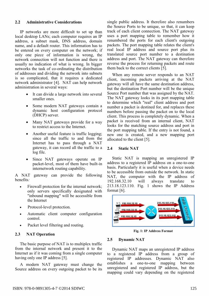
2.5 Dynamic NAT
Dynamic NAT maps an unregistered IP address to a registered IP address from a group of registered IP addresses. Dynamic NAT also establishes a one-to-one mapping between unregistered and registered IP address, but the mapping could vary depending on the registered
ISBN: 978-0-9891305-4-7 ©2014 SDIWC 125
address available in the pool, at the time of communication [7], [8].
In dynamic NAT, the computer with the IP address of 192.168.32.10 will translate to the first available address in the range from 213.18.123.100 to 213.18.123.150. Fig. 2 shows how the dynamic NAT translated IP address.
Fig. 2: Dynamic NAT translated IP Address
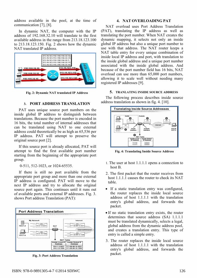
3. PORT ADDRESS TRANSLATION
PAT uses unique source port numbers on the inside global IP address to distinguish between translations. Because the port number is encoded in 16 bits, the total number of internal addresses that can be translated using NAT to one external address could theoretically be as high as 65,536 per IP address. PAT will attempt to preserve the original source port [2].
If this source port is already allocated, PAT will attempt to find the first available port number starting from the beginning of the appropriate port group.
0-511, 512-1023, or 1024-65535.
If there is still no port available from the appropriate port group and more than one external IP address is configured. PAT will move to the next IP address and try to allocate the original source port again. This continues until it runs out of available ports and external IP addresses. Fig. 3. shows Port address Translation (PAT):
Fig. 3: Port Address Translation
4. NAT OVERLOADING PAT
NAT overload uses Port Address Translation (PAT), translating the IP address as well as translating the port number. When NAT creates the dynamic mapping, it selects not only an inside global IP address but also a unique port number to use with that address. The NAT router keeps a NAT table entry for every unique combination of inside local IP address and port, with translation to the inside global address and a unique port number associated with the inside global address. And because of the port number field has 16 bits, NAT overload can use more than 65,000 port numbers, allowing it to scale well without needing many registered IP addresses [9].
5. TRANLATING INSIDE SOURCE ADDRESS
The following process describes inside source address translation as shown in fig. 4. [10].
Fig. 4: Translating Inside Source Address
1. The user at host 1.1.1.1 opens a connection to host B.
2. The first packet that the router receives from host 1.1.1.1 causes the router to check its NAT table.
If a static translation entry was configured, the router replaces the inside local source address of host 1.1.1.1 with the translation entry's global address, and forwards the packet.
If no static translation entry exists, the router determines that source address (SA) 1.1.1.1 must be translated dynamically, selects a legal, global address from the dynamic address pool, and creates a translation entry. This type of entry is called a simple entry.
3. The router replaces the inside local source address of host 1.1.1.1 with the translation entry's global address, and forwards the packet.
ISBN: 978-0-9891305-4-7 ©2014 SDIWC 126

4. Host B receives the packet and responds to host 1.1.1.1 by using the inside global IP destination address (DA) 2.2.2.2.
5. When the router receives the packet with the inside global IP address, it performs a NAT table lookup by using the inside global address as a key. It then translates the address to the inside local address of host 1.1.1.1 and forwards the packet to host 1.1.1.1.
6. OVERLOADING AN INSIDE GLOBAL ADDRESS
One of the main features of NAT is static PAT, also referred to as “overload”. This section explains how to configure PAT by overloading an inside global address. Fig. 5 shows overloading an Inside Global Address.
Fig. 5: Overloading an Inside Global Address
When this overloading is configured, the router maintains enough information from higher-level protocols (for example, TCP or UDP port numbers) to translate the inside global address back to the correct inside local address [11].
When multiple inside local addresses map to one inside global address, the TCP or UDP port numbers of each inside host distinguish between the local addresses [11].
The figure illustrates NAT operation when one inside global address represents multiple inside local addresses. The TCP port numbers act as differentiators. Both host B and host C think they are talking to a single host at address 2.2.2.2. They are actually talking to different hosts; the port number is the differentiator. In fact, many inside hosts could share the inside global IP address by using many port numbers [11].
The router performs the following process in
overloading inside global addresses.
1. The user at host 1.1.1.1 opens a connection to host B.
2. The first packet that the router receives from host 1.1.1.1 causes the router to check its NAT table. If no translation entry exists, the router determines that address 1.1.1.1 must be translated, and sets up a translation of inside local address 1.1.1.1 to a legal inside global address. If overloading is enabled, and another translation is active, the router reuses the inside global address from that translation and saves enough information to be able to translate back. This type of entry is called an extended entry.
3. The router replaces the inside local source address 1.1.1.1 with the selected inside global address and forwards the packet.
4. Host B receives the packet and responds to host 1.1.1.1 by using the inside global IP address 2.2.2.2.
5. When the router receives the packet with the inside global IP address, it performs a NAT table lookup, using the protocol, inside global address and port, and outside global address and port as a key, translates the address to inside local address 1.1.1.1, and forwards the packet to host 1.1.1.1.
7. VIRTUAL LOCAL AREA NETWORK
VLANs have all the same attributes as traditional physical LANs, but allow network devices to be grouped together based on organizational function and application rather than be constrained by geographical or physical location. By creating VLANs, your switched network can consist of multiple segments, each with its own separate broadcast and multicast domains. The VLANs can be set up either statically (where each switch interface is assigned specifically to a VLAN) or dynamically (based on MAC addresses) [12].
Incorporating VLANs into a typical network provides benefits including security, broadcast or congestion control, and management. Through the use of VLANs, users can be isolated from one another; that is, a user in one VLAN cannot access data in a different VLAN. Additionally, VLANs can be thought of as a limited broadcast domain. This means that all members of a VLAN receive broadcast packets that are sent by members of the same VLAN. This logical grouping of users allows
ISBN: 978-0-9891305-4-7 ©2014 SDIWC 127
easier network management. A network administrator can easily move an individual from one group to another without having to reachable the network [12].
VLANs can span multiple switches. For example, you could have Ports 1 through 10 of switch A assigned to VLAN 1, and Ports 11 through 20 of switch A assigned to VLAN 2. If switch A and switch B share a high-speed link, then switch B could also have ports assigned to the same VLANs as switch A. Fig. 6. shows Basic VLAN Configuration:
Fig. 6: Basic VLAN Configuration
8. ROUTING TABLES AND PROTOCOLS
The creation and maintenance of the routing table are critical to the operation of a router. The creation and updating of the routing table may be undertaken manually (by human network administrators, in which case the router is said to perform static routing), but this is impractical in most networks. Alternatively, routing table creation and maintenance may be undertaken automatically by the routers (in which case the routers perform dynamic routing). Fig. 7 shows next hop determination by routers using their routing table [13].
Fig. 7: Next Hop Determination By Routers
Using Their Routing Table
Most routers even allow for a mix of the two methods, which allowing some routing table entries
to be maintained statically, while leaving the rest to be dynamically maintained.
9. INTER VLAN ROUTING
In order for network devices in different VLANs to communicate, a router must be used to route traffic between the VLANs. While VLANs help to control local traffic, if a device in one VLAN needs to communicate with a device in another VLAN one or more routers must be used for inter VLAN communication [14].
Topology where inter VLAN routing would be necessary for PCs in one VLAN to communicate with PCs in other VLANs. The router has two interfaces with 802.1Q encapsulation enabled and multiple VLANs configured on each. For PC1 in VLAN2 to communicate with PC2 in the same VLAN, PC1 simply sends a packet addressed to PC2.
The switch will forward the packet directly to the destination PC without going through the router. However, for PC1 to send a packet to PC5, the switch will have to place a VLAN2 tag on the packet and forward the packet on Trunk A to the router.
The router will remove the VLAN2 tag, determine the appropriate outgoing interface based on the IP route table, place a VLAN4 tag on the packet, and send it out on Trunk B. The switch in VLAN4 that receives the packet will forward it directly to PC5. Fig. 8. shows a topology where inter VLAN routing [14].
Fig. 8: Inter_VLAN Routing Topology
10. SIMULATION SCENARIO
Simulation Scenario based on a Packet Tracer
5.0v. Packet Tracer is a protocol simulator
developed at Cisco Systems. Packet tracer is a
powerful, dynamic, self-paced, visual, interactive
simulation tool that displays the various protocols
ISBN: 978-0-9891305-4-7 ©2014 SDIWC 128

used in networking. The Simulation Scenario
consists of two nodes, Cisco router, and switch.
10.1 Static NAT
Static NAT is used when outside users are
trying to access the internal resources [15]. Fig. 9.
shows configuration of static NAT.
Fig. 9: Static NAT
Configuration
Ip nat inside source static 10.1.1.1
170.46.2.2
Interface ethernet0/0
Ip address 10.1.1.10 255.255.255.0
Ip nat inside
Interface serial0
Ip address 170.46.2.1 255.255.255.0
Ip nat outside
10.2 Dynamic NAT
The router is given a pool of IPs that contains
global IPs, so every user tries to access a public
network will be given an IP from the pool. Fig. 10.
shows the configuration of Dynamic NAT.
Fig. 10: Dynamic NAT Configuration
10.3 NAT Overload PAT
Static or Dynamic NAT provide only one to one
translation, while PAT supports many to one
translation using port numbers. Fig. 11, shows
NAT overload PAT.
Fig. 11: NAT Overload PAT
Configuration Ip nat pool globalnet 170.168.2.1
170.168.2.1
netmask 255.255.255.0
ip nat inside source list 1 pool
internet overload
interface ethernet0/0
ip address 10.1.1.10 255.255.255.0
ip nat inside
interface serial0/0
ip address 170.168.2.1 255.255.255.0
ip nat outside
access-list 1 permit 10.1.1.0
0.0.0.255
10.4 Inter_VLAN Routing
The network topology above represents a simple
network that requires a router for communication
ISBN: 978-0-9891305-4-7 ©2014 SDIWC 129
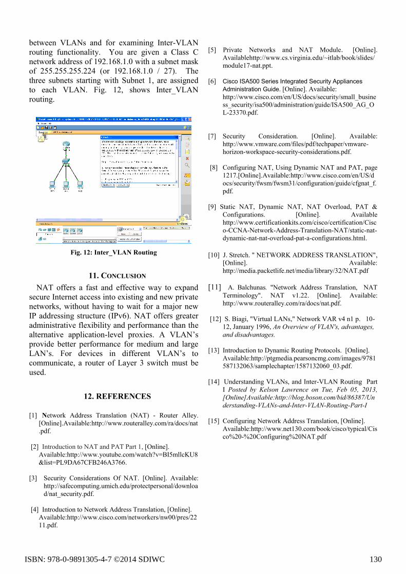
between VLANs and for examining Inter-VLAN
routing functionality. You are given a Class C
network address of 192.168.1.0 with a subnet mask
of 255.255.255.224 (or 192.168.1.0 / 27). The
three subnets starting with Subnet 1, are assigned
to each VLAN. Fig. 12, shows Inter_VLAN
routing.
Fig. 12: Inter_VLAN Routing
11. CONCLUSION
NAT offers a fast and effective way to expand
secure Internet access into existing and new private
networks, without having to wait for a major new
IP addressing structure (IPv6). NAT offers greater
administrative flexibility and performance than the
alternative application-level proxies. A VLAN’s
provide better performance for medium and large
LAN’s. For devices in different VLAN’s to
communicate, a router of Layer 3 switch must be
used.
12. REFERENCES
[1] Network Address Translation (NAT) - Router Alley.
[Online].Available:http://www.routeralley.com/ra/docs/nat
.pdf.
[2] Introduction to NAT and PAT Part 1, [Online].
Available:http://www.youtube.com/watch?v=BI5mllcKU8
&list=PL9DA67CFB246A3766.
[3] Security Considerations Of NAT. [Online]. Available:
http://safecomputing.umich.edu/protectpersonal/downloa
d/nat_security.pdf.
[4] Introduction to Network Address Translation, [Online].
Available:http://www.cisco.com/networkers/nw00/pres/22
11.pdf.
[5] Private Networks and NAT Module. [Online].
Availablehttp://www.cs.virginia.edu/~itlab/book/slides/
module17-nat.ppt.
[6] Cisco ISA500 Series Integrated Security Appliances
Administration Guide. [Online]. Available:
http://www.cisco.com/en/US/docs/security/small_busine
ss_security/isa500/administration/guide/ISA500_AG_O
L-23370.pdf.
[7] Security Consideration. [Online]. Available:
http://www.vmware.com/files/pdf/techpaper/vmware-
horizon-workspace-security-considerations.pdf.
[8] Configuring NAT, Using Dynamic NAT and PAT, page
1217.[Online].Available:http://www.cisco.com/en/US/d
ocs/security/fwsm/fwsm31/configuration/guide/cfgnat_f.
pdf.
[9] Static NAT, Dynamic NAT, NAT Overload, PAT &
Configurations. [Online]. Available
http://www.certificationkits.com/cisco/certification/Cisc
o-CCNA-Network-Address-Translation-NAT/static-nat-
dynamic-nat-nat-overload-pat-a-configurations.html.
[10] J. Stretch. " NETWORK ADDRESS TRANSLATION",
[Online]. Available:
http://media.packetlife.net/media/library/32/NAT.pdf
[11] A. Balchunas. "Network Address Translation, NAT
Terminology". NAT v1.22. [Online]. Available:
http://www.routeralley.com/ra/docs/nat.pdf.
[12] S. Biagi, "Virtual LANs," Network VAR v4 n1 p. 10-
12, January 1996, An Overview of VLAN's, advantages,
and disadvantages.
[13] Introduction to Dynamic Routing Protocols. [Online].
Available:http://ptgmedia.pearsoncmg.com/images/9781
587132063/samplechapter/1587132060_03.pdf.
[14] Understanding VLANs, and Inter-VLAN Routing Part
I Posted by Kelson Lawrence on Tue, Feb 05, 2013,
[Online]Available:http://blog.boson.com/bid/86387/Un
derstanding-VLANs-and-Inter-VLAN-Routing-Part-I
[15] Configuring Network Address Translation, [Online].
Available:http://www.net130.com/book/cisco/typical/Cis
co%20-%20Configuring%20NAT.pdf
ISBN: 978-0-9891305-4-7 ©2014 SDIWC 130