Embed Size (px)
Citation preview

Simulation of forging processes


3
Editor’s Foreword
Modern technical systems – in the automotive, avi-
ation and aerospace sector as well as in mechanical
engineering and the field of energy technology –
often involve high-performance forged compo-
nents. Their key role is based on the one hand on
their enormous load-bearing capacity required for
the transmission of high forces and momentums.
On the other hand, it can be observed that in times
of increasingly scarce resources there is a growing
demand for efficient industrial production processes
– as is the case for forging.
Especially in the automotive industry, increasing
demands with respect to lightweight design and
power density call for the ever more intensive op-
timization of components, which requires the ca-
reful matching of alloy, component geometry and
the many parameters along the entire design and
manufacturing process chain. By involving the
supplier in the product development process and
in engineering partnerships early on, favourable
conditions are created for finding economical solu-
tions that benefit both parties.
The previous edition of this EXTRA-Info “Simulati-
on in the forging industry“ dealing with simulation
described the experience of individual companies
and highlighted general solutions based on these
case studies. In this second, completely redesigned
edition, the editorial advisory board has opted for a
different approach.
The numerous areas of application and further
development of simulation systems presented in
this EXTRA-Info in conjunction with the anticipated
research results highlight ongoing progress in the
field of virtual tools for forging applications. Parti-
cularly noteworthy in this context are developments
in the area of basic research aimed at a better un-
derstanding of the processes within the workpiece
and tool, opening up new possibilities for targeted
technical progress.
The description of the use of virtual tools to deve-
lop intelligent solutions for the implementation of
special features, tolerances and component pro-
perties should appeal not only to the forging sector
and its customers. Likewise, the intention is also to
win over the younger generation – especially tech-
nically-minded young people who want to actively
participate in future technologies – for the sector.
Furthermore, the description of the entire process
chain from product development using modern CA
and simulation techniques through the selection of
materials to determining the design of procedures
or combinations of methods can be a valuable aid in
apprenticeships and academic studies.
We are pleased to present to all parties interested
in forging, by means of the EXTRA-Info documen-
tation as a whole and more specifically with this la-
test edition, an effective support for issues linked
to modern and forward-looking ways of developing
products and processes virtually. The greatest tribute
to the participants, especially to the editorial board,
would be to make frequent and active use of this
document.
B. A. Jochen Heizmann
Hirschvogel Automotive Group
Chairman of the FEM Working Group
Dipl.-Ing. Hans Ulrich Volz
Jung, Boucke GmbH & Co. KG
Chairman of the Public
Relations / Technical Information Committee
58093 Hagen, April 2013

4
Imprint
Author: Dipl.-Ing. Klaus Vollrath, Aarwangen, Schweiz
Editoral advisory board: Dipl.-Ing. Torsten Feldhaus, CDP Bharat Forge GmbH, Ennepetal
Dipl.-Ing. Michael Fiderer, Kistler Automotive GmbH, Schönaich
Dipl.-Ing. Christoph Gröbel, SONA BLW Präzisionsschmiede GmbH, Remscheid
Dipl.-Ing. Pablo Guel-López, Seissenschmidt AG, Plettenberg
Volker Mensing, simufact engineering GmbH, Hamburg
Dipl.-Ing. Thomas Risse, Siepmann-Werke GmbH & Co. KG, Warstein
Dipl.-Math. Sabine Widdermann, Industrieverband Massivumformung e. V., Hagen
Dipl.-Ing. Michael Wohlmuth, simufact engineering GmbH, Hamburg
Senior Editor: B. A. Jochen Heizmann, Hirschvogel Automotive Group, Denklingen
Figures: See Image Directory page 63
Responsible for
the overall production: Industrieverband Massivumformung e. V. (German Forging Association), Hagen
Dorothea Bachmann Osenberg
Layout and setting: simplon.
Agency for advertising and design, film, audio and new media, St. Ingbert
Publication-No.: EI-Sim-e-0413-10sim
Printed: April 2013
ISBN: 978-3-928726-31-3
Copyright. All rights reserved, including those for translating and copying. No reproduction of excerpts is permit-
ted without prior permission of Industrieverband Massivumformung e. V. and without including source reference.
Publications of the Industrieverband Massivumformung e. V. are based on the results of joint research of the com-
panies adhering to the Industrieverband Massivumformung e. V. (German Forging Association).

5
Forging Industry Information Service, Special Edition
Publisher:
Industrieverband
Massivumformung e. V.
Goldene Pforte 1
58093 Hagen, Germany
Tel.: + 49 2331 958830
Fax: + 49 2331 958730
E-mail: [email protected]
www.metalform.de
Simulation of forging processes

6
Seite
Editor’s Foreword 3
Imprint 4
1 Introduction 8
2 Developing forged parts requires process know-how 9
2.1 Making use of the forger’s process expertise 9
2.2 Modern simulation tools 10
2.3 Expertise remains the key factor 11
3 Virtual tools in product development 12
3.1 Sequence and scope of FEM simulation applications 12
3.1.1 Integration of two forged parts into one 13
3.1.2 Substituting a casting by a forged solution 14
3.1.3 Substituting a part made from sheet metal 15
3.1.4 Optimization of spur gears 16
3.1.5 Optimization of an aluminium wheel 17
3.2 Using advanced simulation technologies 18
3.2.1 Adjusting the design of differential bevel gears 19
3.2.2 Simulation-based optimization of a constant-velocity joint 20
3.2.3 Optimizing the design of connecting rods 21
3.3 No substitute for creativity 22
3.3.1 Advantages of precision forging gear wheels compared of machined ones 22
3.3.2 Disk carrier for transfer clutch 23
4 Simulation along the forging process chain 24
4.1 Using simulation in a steel mill 24
4.2 Material pretreatment 26
4.3 Separation 27
4.4 Heating 28
4.5 Forging 29
4.5.1 Designing forging sequences 29
4.5.2 Analysis of tool-related defects 30
4.5.3 Trimming / punching and stamping / sizing 31
Contents

7
Seite
4.6 Machining forged parts 32
4.7 Heat treatment 33
4.7.1 Hardening and tempering 33
4.7.2 Case hardening 34
4.7.3 Induction hardening 35
4.8 Post-processing surface treatment 36
5 Advances in the field of simulation 38
5.1 Development trends 38
5.1.1 Improved accuracy of calculation results 38
5.1.2 Modeling the interaction between tools and machine 38
5.1.3 Simulation of the entire process chain 39
5.1.4 Predicting component properties 40
5.1.5 Minimizing computation times 41
5.1.6 Automatic optimization of manufacturing concepts 41
5.1.7 Use of expert systems 43
5.2 Progress in understanding basic principles 44
5.2.1 Alloy database using steel alloys as an example 44
5.2.2 Influence of the heating rate on the formability
of steel and aluminium 45
5.2.3 Alloy and process design using thermodynamics
and microstructure modeling 45
5.2.4 Robustness of the modeling of microstructures
when designing a drop forging process 46
5.2.5 Modeling the friction between workpiece and tool 47
5.2.6 Coupling of forging simulation with non-linear forging press models 50
5.2.7 FEM simulation of tool failure in hot forging processes 51
5.2.8 Controlling damage in cold forging processes 52
5.2.9 Development of holistic approaches 52
6 Economic aspects 55
7 Outlook 57
8 Bibliography 59
9 Illustrations 63

8
Introduction
Among other factors, the well-being of modern
civilizations is the result of constant innovation,
allowing us to manufacture and market more and
better products at lower costs and thus to improve
the living conditions of the vast majority of people.
Some major drivers of this innovation are modern
production concepts that optimize resources and
expertise across company borders and along the en-
tire process chain from raw material to the finished
product. The most efficient approach to optimizing
expenditure is inviting suppliers to contribute to the
development of new products as soon as possible
during the design phase, so that they can contri-
bute their skills at an early stage. This advice stems
from the knowledge that the expenditure required
to manufacture a product is largely determined du-
ring the first stages of the design process: experts
estimate that about 80 % of the costs of producing
a component are fixed during the first 20 % of its
design phase. This brochure shows the multiple and
far-reaching possibilities available to the forger by
using modern, high-performance IT tools to simula-
te processes and workpiece properties.
1

9
Developing forged parts requires process know-how
For an optimal product design comprehensive know-
ledge of the manufacturing process is essential for
the best utilization of process-related advantages
and thus to ensure optimum product characteristics:
every designer is familiar with the fact that in practi-
ce it is virtually impossible to substitute a production
process such as casting by other processes such as
forging or welding without having to radically read-
just the part geometry, Fig. 2.1 This refl ects the re-
cognition that the process “makes” the product. By
this we mean that the characteristics of a mechani-
cal component can differ signifi cantly depending on
how the process used to form its contours has been
implemented. In addition to this, the typical aspects
of (large-scale) series production, such as costs qua-
lity assurance and minimized resource consumption,
are also included, so that the production process
and its specifi cs will fi nally take on a lead role.
The best advice for the customer’s R&D engineers is
thus to team up with the supplier’s staff in the early
stages of the design phase. In principle, this can even
be recommended as soon as basic performance re-
quirements with respect to space, interfaces or load
conditions, as well as additional requirements, for
example with respect to corrosion resistance, are de-
fi ned. Occasionally it might even make sense in the-
se circumstances to seek the advice of the supplier
also with respect to the production process or even
to the type of material, especially if additional light-
weight aspects play a role. Following the example of
the automotive industry, more and more other in-
dustrial sectors are therefore inviting their suppliers
to participate in the design process early on in the
concept phase. This also results in the interaction of
two different virtual worlds: the designer’s “classic”
CAD software packages, which cannot model the
local distribution of fi eld variables and properties,
versus the supplier’s process-oriented simulation
tools, which take into account the production pro-
cess and its numerous peculiarities, including its im-
pact on the properties of the component.
2.1 Making use of the forger’s process expertise
By performing simultaneous engineering together
with the forger it is possible to unlock a plethora of
capabilities because in the design phase that follows
the concept-fi nding stage the forging specialists
have a key advantage. Due to their in-depth know-
ledge of the limits and advantages of their produc-
tion process, several “expert systems” are up and
running – so to speak – at the back of their head.
These automatically check the process technicalities
and cost-benefi t aspects of their craft. For example,
a forging professional will often see at fi rst glance
where a radius should be re-examined to determine
if it may affect the durability of the forging tool.
Likewise, machinability aspects will also be conside-
red, from clamping surfaces and fi xtures to questi-
ons such as whether a given surface can still be ma-
chined with standard tools, or if any special devices
may have to be procured for the task. Furthermore,
other benefi ts along the entire process chain up to
the end user may materialize, such as achievable
weight savings or improved performance characte-
ristics, Fig. 2.2.
Fig. 2.1: Process-oriented design of the present-day forged aluminium rear axle support (left) for a passenger car as compared to a cast steel version (right)
2

10
2.2 Modern simulation tools
The different forging processes and the wide varie-
ty of materials make it possible to achieve a highly
accurate tune of sometimes quite varying proper-
ties in different areas of the same component as
well as to optimize expenditure and cost along
the downstream supply chain. In order to be able
to meet his challenging tasks as an engineering
partner, the modern forger can draw on highly so-
phisticated simulation tools. These mathematically
depict the numerous steps in the development
and manufacturing process, from the acquisition,
modifi cation and generation of CAD data through
complex software for simulation and optimization
of forging components and processes down to the
design of the downstream process chain, Fig. 2.3.
Fig. 2.3: A typical development process chain with the virtual tools used
Customer
CAD / FEM Component Layout
Component Requirements
CAD / FEM Process Layout
CAD / FEM Tool Design
CAM
CAQ
Tool Manufacturing
Production
Inspection
Component Testing
Component DispatchCustomer
FEM Structural Analysis
Fig. 2.2: Cold forged pinion: simulation result and real part
2

11
Depending on the specifi cs of the given company,
working steps such as computer-aided optimization
of the component topology, followed by redesign
and analysis of component behaviour, may be un-
dertaken using suitable fi nite element method (FEM)
software. Sometimes even more specialized simula-
tion tools are used, e. g. for optimizing gear wheel
design or even whole assemblies such as differential
gears, for dimensioning constant-velocity joints or
for fi ne tuning piston rod shapes.
2.3 Expertise remains the key factor
Thanks to faster software and more powerful hard-
ware, the mathematical models employed in the
software the forger uses to simulate his processes
have made great advances with respect to the band-
width of applications as well as to the accuracy of
their forecasts in recent years. Nevertheless, it must
be borne in mind that simulation tools are exactly
what their name implies, namely tools with specifi c
properties for a particular purpose. The programs
currently available are very powerful instruments
that enable the forger to provide his customer with
signifi cant benefi ts. The input of data on initial and
boundary conditions as well as material-related in-
formation is necessary for the calculation. These
material data are often provided by the software
house in the form of databases as well as being ex-
perimentally determined in the forging companies
or by scientifi c institutes. Moreover, such simulation
tools will yield their full benefi ts only in the hands of
an experienced specialist with in-depth knowledge
of his processes and the ability to assess the perfor-
mance of the software. The same specialist should
therefore be left to decide for what purpose and to
what extent he intends to use these tools for the
task in hand, Fig. 2.4.
Fig. 2.4: Simulation can depict even intricate kinematics, here to the example of open die forging
2

12
In the forging sector, product and process deve-
lopment tasks regularly include the use of simula-
tion software. In this respect, a distinction should
be made between two basic categories: commer-
cial software based on the fi nite element method
(FEM) as compared to proprietary programs based
on analytical approaches that in some cases have
been specifi cally developed within a given company.
Such FEM programs not only make it possible to sol-
ve mechanical structural problems arising during the
product development phase. They can also simulate
the evolution and local distribution of thermo-me-
chanical and elastic characteristics when a manufac-
turing process is being designed.
The subsequent paragraphs describe basic steps in
performing FE analyses. Furthermore, the use of
advanced simulation tools in forging companies is
discussed and forgers’ creativity presented.
3.1 Sequence and scope of FEM simulation applications
When setting up the process model, the fi rst step
is to create a 3D CAD representation of the inter-
acting objects, which will then be passed on to the
so-called pre-processor of the FE software. Sub-
sequently, the component to be examined or the
assembly space to be considered is divided into a
multitude of small volume elements with defi ned
dimensions, the so-called fi nite elements. Further-
more, the boundary conditions are applied to the
fi nite element model and the material data added.
Afterwards, the complete model is transferred to
the so-called solver, who will compute a solution.
Then the results can be viewed and evaluated on-
screen in the form of graphics or animations with
the help of a so-called post-processor, Fig. 3.1. This
Virtual tools in product development
3 FEM – Solver
FEM
1 CAD Geometries 2 FEM – Pre-Processor
4 FEM – Post-Processor
Upper die
Billet
Lower die
Meshed billet
Presentation of results
Fig. 3.1: To prepare for the simulation, the three-dimensional CAD image of the billet is subdivided into numerous minuscule volume elements. During calculation the solver “closes” the tool in small steps and calculates the changes for each step
3

13
makes it possible to look on while the billet is defor-
med in the forging process and the material fi lls the
cavity of the die. Although such calculations usually
require enormous computing power, thanks to the
high performance of modern computer systems and
related advances in recent software developments,
nowadays they can be performed within acceptable
time limits.
3.1.1 Integration of two forged parts
T. Feldhaus [FELD 1] describes a well-performed
integration of two previously separate forgings to
form a single integral part. The starting point of the
development project was a assembly for truck axles
consisting of two separate forgings, a stub axle and
a steering arm, Fig. 3.2. The two parts were joined
by two screws. Compared with an integral solution
combining the functions of the two separate parts
in one monolithic component, this solution entailed
several serious disadvantages. All the high dynamic
stresses this connection is subjected to run through
the screws. To compensate for the fact that, as a
result of notch effects, the threads represent a criti-
cal factor under dynamic load conditions, their size
had been adjusted to the upside. This in turn forced
the designers to provide massive walls around the
threaded bores and blind holes in order to ensure
adequate support. Additionally, both parts had to
be forged, machined and tested in separate produc-
tion processes before being joined by screwing in a
quality-assured assembly process that had to comply
with specifi c requirements.
The main reason for this arduous procedure was the
fact that in the past, due to the lack of suffi ciently
powerful tools able to simulate the forging process,
the designers were not able to mathematically re-
present the extremely challenging forging process
for the production of this integrated forging with
suffi cient accuracy of the results. The risk of not
being able to produce this part with the high degree
of process mastery required for such safety parts
was too great. This necessitated many loops in the
production process, driving the process costs even
higher.
This changed in the 2010s thanks to the increased
mastery of such developmental tasks resulting from
rapid advances in software to simulate forging pro-
cesses. So it became possible to design and opti-
mize the elaborate preparatory processes for sha-
ping the forging billet in line with the requirements
of the fi nal forging operation on-screen. After a
practicable process path had been identifi ed, the
next step consisted of defi ning the optimal com-
ponent geometry. In this case, optimization of the
high
von Mises effective stress
low
Fig. 3.2: The FEM analysis of a braking load case reveals that in the vicinity of the integrated steering arm the blue areas with low stress levels, indicating oversizing, are signifi cantly reduced
Steering arm
Steering arm
3

14
topology was not yet available as a fully automatic
software tool. Instead, the designer had to direct-
ly establish the geometry by manually performing
several iteration loops. For this purpose a reaso-
nably suitable design was generated, which was
then subjected to given loads using FEM simulati-
on software. This made it possible to identify areas
subjected to particularly high or low stress levels.
After any necessary corrections had been made by
the designer, the modifi ed geometry was subjected
to the same analysis. This iterative procedure was
repeated until the results met the developers’ ex-
pectations. A further important contribution to the
realization of this type of integrated part resulted
from the truck manufacturer reducing the number
of variants in the geometry of the levers he uses.
With this refi ned geometry, the fi nal simulation
of the forging process and the design of the tools
were tackled. The ultimate success of these actions
was a slim integral part that was 25 % lighter than
the previous version – a very gratifying contribution
to fuel economy and CO2 reduction, especially in
view of the high mileage of heavy trucks. A further
bonus comprised substantial savings in machining
and assembly costs along the supply chain through
to the ready-to-assemble stub axle.
3.1.2 Substituting a casting
by a forged solution
M. Dahme et al. [HIVO 1] report on a very extensive
partnership between a forger and a vehicle manu-
facturer involving the comprehensive use of simula-
tion tools. The starting point was a request from the
customer regarding possible alternatives for a stee-
ring knuckle the previous version of which had been
designed as a steel casting. Starting from a rough
concept designed as a welded structure, the forger
was provided with a set of specifi cations, including
the construction space needed, service load cases
and additional functions and requirements. The spe-
cial feature of the inquiry was that the customer was
willing to accept advice from his supplier right from
the start of the project and was ready to consider
an alternative production method and even subs-
tituting materials (aluminium alloy instead of steel
casting), Fig 3.3.
The fi rst step was a redesign with the aid of soft-
ware providing automatic topology optimization.
With this in mind, the new FE model of the con-
struction space initially included the total volume
available. For the subsequent optimization loops
this construct was subjected to the given loads and
the resulting stress distribution in the material was
computed. In areas with low stress levels, “virtual
material” was successively removed before initiating
the next iteration loops. This procedure was repea-
ted until a relatively uniform stress distribution was
achieved throughout the volume of the workpiece.
In other words, the material remaining in the com-
ponent is optimally used in all locations. In perfor-
ming such tasks modern programs can already allow
for manufacturing boundary condition constraints,
such as taking into account draft angle or avoiding
undercuts, which cannot be achieved by forging.
For the next step, the model resulting from the fi nite
element analysis had to be converted into a CAD
model, with the designer taking other manufactu-
ring technicalities, such as rib widths and radii, into
account. In this process the forging designer relies
on his experience to develop an aluminium steering
Fig. 3.3: Example of a comprehensive joint development pro-cess starting with an initial welded assembly (top left) trough material substitution, topological optimization, CAD model, structural analysis, prototype manufacturing, machining of tools, forging simulation, measurement and testing of aprts to the fi shed component for a premium segment car producer
3

15
knuckle that can be produced by forging from the
still very immature FE result. But even this solution
still leaves room for improvement. For instance, alt-
hough the material is largely optimally distributed in
the component, certain geometric elements should
be redesigned, taking account of local stress distri-
butions, which can contribute to a signifi cant reduc-
tion of stress peaks. The minimum requirement for
shape optimization is that the maximum stress levels
predetermined by the choice of material are not ex-
ceeded and that elastic deformations of the com-
ponent remain within prescribed limits. The com-
ponent model is therefore once again subdivided
into fi nite elements. For the calculation the specifi ed
loads are entered as boundary conditions. Only then
will the forger use the resulting design model for the
next step of designing the actual sequence of stages
for a forging process, i. e. the virtual simulation of
the forming process on his computer. This step is
also supported by simulation. Information obtained
in this way can result in further optimization of com-
ponent design in the course of additional iteration
loops.
Only then will prototypes be made and tested –
based on the CAD model thus obtained. Further-
more, the model serves as a template for numerous
additional simulation computations along the pro-
cess chain from tool design to the selection of ma-
chines and peripherals down to CNC machining
processes. Many of these calculations, as well as
fatigue testing, are performed in close cooperation
with the customer, together with his staff and using
his resources. The outcome of such cooperative si-
multaneous engineering processes is well-designed
components as well as production processes that
are mastered at a high level and can be ramped up
quickly.
3.1.3 Substituting a part made
from sheet metal
The successful substitution of a car control arm
originally designed as a sheet metal part by a for-
ging is described by M. Bachmann [BACH 1]. The
starting point of the development project was an
urgent customer request because the original solu-
tion had proved to be impractical relatively late in
the development process. The forger, acting as a
“knight in shining armour” was thus granted only
six months for the development (from the fi rst in-
quiry to the start of production) instead of the usual
three-year period. Without resorting to the massive
use of simulation software, the forging designers
would have stood no chance of making up for this
huge delay. Yet the remaining time was not suffi ci-
ent to come up with an in-depth topology redesign
refl ecting the particularities of the new manufactu-
ring process. For this reason, the resulting forged
part geometry still closely refl ects the contours of
the original sheet metal design and its large-area,
thin-walled geometry is not easy to forge. For
example, the thin walls impede the fl ow of the
material in the die. In order to ensure that the tool
can be fi lled satisfactorily in spite of this, the billet
has to undergo complex multi-stage operations to
predistribute the material prior to the actual forging
operation, Fig. 3.4. Thanks to the use of simulation,
further special adjustments required were identifi ed
in time to include them in the tool design before the
start of production.
Another key aspect comprised strict requirements
with regard to the behaviour of the components
Fig 3.4: In order to ensure a satisfactory fi lling of the mold, the billet has to be subjected to a number of sophisticated pre-forming stages prior to the forging pro-cess. The entire sequence of production stages consists of 4 rolling passes, bending, fl attening, pre-forging, fi nish forging, trimming / calibration and surface treatment
3

16
in the event of abusive overloading. In this respect
particularly restrictive requirements prescribed that
buckling should occur at a predefi ned location in
order to avoid undue deformations, e. g. in the vici-
nity of the bearings. Their implementation called for
corresponding adjustments in the forging process, for
example by narrowing the usual forging tolerances.
Another problem also coming along with the thin-
walled geometry was extremely high press forces
during the fi nal forging stage. This would have
required using much too large a machine, which
would have exceeded the limits set by the budget.
Here too, the simulation proved benefi cial because
it could predict the press forces with a high level
of accuracy, Fig. 3.5. The computation revealed
that the required maximum load would remain just
within the tolerance requirements of a smaller and
thus more economical machine.
3.1.4 Optimization of spur gears
The successful use of simulation for the optimization
of spur gears for the automotive sector is reported
by S. Huber et al. [HUBE 1]. The starting point of the
development comprised spur gear sets for camshaft
drives used in modern engines to replace toothed
belts. The focus was on reducing weight by realizi-
ng so-called wave-profi le connections between the
hub and sprocket instead of the usual T-bar profi le,
Fig. 3.5: Forming simulation make it possible to accurately predict the pressing forces and thus decide in favour of a smaller and more economical production unit
Fig. 3.6: Helical gears with different connection profi les: a T-bar connection (left) and a perforated wave profi le connection (right)
3,000
2,500
2,000
1,500
1,000
500
0
1.4
1.2
1.0
0.8
0.6
0.4
0.2
0.0
0.05 0.06 0.07 0.08 0.09 0.1
Time / s
Press force chartContact / mm
Pres
s fo
rce
/ t
3

17
Fig. 3.6. The challenge lay in the demanding me-
tal forming technology required to achieve such
wave-profi led gears. In particular, this necessitated
accurate predistribution of the billet material in the
precursory stages in order to avoid wear on the for-
ging tools – especially on the form punch of the fi -
nal forging stage with the crown or wave contour.
An uneven load cases of the forging material on the
fl anks of the protruding areas of the punch and in
the die would put them at particular risk of abra-
sive wear and fracture. The corresponding forming
stages were therefore comprehensively investigated
and optimized using simulation software.
Another aspect of this development was to mini-
mize the allowances required when milling the ge-
ars in the “green“, i. e. non-hardened state. These
allowances are required to make up for distortions
which the component may sustain as a result of the
hardening process prior to the fi nal fi nishing of the
gears by grinding. Since grinding in the hardened
state is a very expensive operation, any reduction
of the related allowance has a positive impact on
costs. Tests showed that with respect to the grinding
allowance per tooth, a reduction of 0.05 or 0.1 mm
was possible, resulting in signifi cant cost and time
savings.
Other benefi ts were noted when analyzing key cha-
racteristics such as the von Mises equivalent stress
in the web area between the hub and sprocket, as
well as the total deformation in the sprocket area,
by means of an FEM analysis, Fig. 3.7. Additional
studies revealed that using a wave-profi le connec-
tion makes it possible to slim down the support
area beneath the sprocket teeth. Taking the ex-
ample of a gear with a diameter of 110 mm and
a tooth height of 8 mm, the redesign resulted in
weight reduction-values between 60 and 100 g,
with a related reduction of the moment of inertia.
Depending on the design variant, weight savings of
up to 10 % can be achieved.
3.1.5 Optimization
of an aluminium wheel
P. Olle [OLLE 1] reports on progress in the deve-
lopment of forged aluminium wheels based on
the example of a “historical“ classic wheel. Since
for this wheel a retro look and modern-day wheel
dimensions had to be blended, the striking design
of the late 60‘s had to remain recognizable. In spite
of this, the new wheel had to sport an optimally
light weight without negatively affecting its fatigue
strength. The latter aspect had particularly high
priority for the designers, not least with a view to
minimizing the unsprung mass of the vehicle in or-
der to enhance driving comfort.
Wheels are safety components that, due to their di-
rect contact with the road surface, are subjected to
Fig. 3.7: Total deformation in mm: a perforated T-profi le (left) and a perforated wave profi le (right)
Total deformation / mm
max. 0.2 mm
0 0.025 0.05 0.1 0.11 0.12 0.13 0.14 0.15
3

18
especially high dynamic loads. So their resistance to
fatigue had to be proved not once but twice, using
two different dynamic test procedures: a classic ro-
tating bending test (UBP) and the biaxial wheel test
(ZWARP) developed by the Fraunhofer Institut für
Betriebsfestigkeit und Systemzuverlässigkeit (LBF),
each performed with load spectra refl ecting practi-
cal service conditions. Both tests can be simulated
using special FEM software. The UBP simulation is
modeled, computed and evaluated partly automa-
tically, while the pre-processing of a ZWARP simu-
lation is carried out using simulation tools specially
designed for wheels.
Developing the new wheel design thus required
regular optimization loops between the CAD soft-
ware, forging simulation and the programs used to
evaluate service life. In order to preserve the distinc-
tive look, design changes were only permitted on
the brake side of the wheels, Fig. 3.8.So reducing
weight without changing the look was achieved
by forging topology-optimized pockets as well as
by adding blind holes between the mounting holes
on the spokes (Fig. 3.9). After each optimization
loop the effects on the forgeability of the contour
as well as compliance with service life requirements
had to be re-checked by computation. From the
perspective of the developers it was interesting to
note that over the years they were able to not only
signifi cantly reduce weight, but moreover – thanks
to improved simulation tools – shorten the time
required to develop forged aluminium wheels. To
a considerable extent this was attributable to the
service life computations. Certifi cation tests could
therefore be carried out on optimally designed
wheels. This made it possible to signifi cantly reduce
the amount of work required for service life tests in
the lab. Likewise, time-consuming and costly read-
justments of the wheel design, which would have
necessitated further development loops, could be
avoided. Right from the outset, the wheels could be
designed with consistently high component utiliza-
tion. The result is an extremely lightweight product
that still meets all safety requirements.
3.2 Using advanced simulation technologies
The more closely the forger is involved in the joint
development of new products, the more compre-
hensive the reach of the advanced software he
uses to simulate the characteristics of the product
to be designed in order to achieve an optimized
solution often becomes. To this end, he relies on
his wide-ranging knowledge of the relationship
between the functional properties of a component
and the characteristics of the production process.
Some related examples are presented in the fol-
lowing chapters.
Fig. 3.9: The investigation of the dynamic strength based on an FEM analysis shows that the edges of the weight-reducing pockets had to be designed with special care
Fig. 3.8: The brake-side CAD view shows the weight-reducing pockets forged in the spokes as well as the additional blind holes on the spokes between the screw-mounting bores
3

19
3.2.1 Adjusting the design
of differential bevel gears
When developing new differential bevel gears, the
designer has to fi nd suitable solutions on the ba-
sis of customer specifi cations [RUE 1]. With this in
mind, the forger usually receives a description with
detailed specifi cations and requirements regarding
construction space, interfaces, load cases to be con-
sidered and the maximum total weight. The example
presented here deals with a bevel gear that had to be
newly designed from scratch. One special feature
was an extremely high tolerance to displacements
caused by external forces.
The usual procedure in such cases is to create a fi rst
rough design of the geometry using a CAD pro-
gram, with the aim of determining the maximum
fl ank length and load bearing capacity achievable
within the prescribed construction space. The va-
riables that have to be considered at this stage of
development include, among others, the number of
teeth, with the designer’s experience playing a ma-
jor role. For example, he must allow for the fact that
not every geometry a CAD system can deliver lends
itself to being forged economically later on.
In the next development stage, details of the tooth
design have to be studied in order to achieve an op-
timum load bearing capacity. For these calculations,
a DIN calculation program from the Forschungsver-
einigung Antriebstechnik is used. Over the years, the
forging specialists have added further routines to
this standard program, refl ecting their special know-
how and experience. For the project presented here,
some 10,000 variants were designed, computed on
the basis of a wide variety of application scenarios
and the results assessed. Here too, the forger’s spe-
cial know-how lies in how specifi cations and cons-
traints should be parameterized and how the best
solutions can be identifi ed.
Based on these results, the geometry of the gear
is subsequently established using a CAD program.
The base geometry is then complemented by diverse
subtleties, such as tooth fl ank crowning, tooth base
curvature between the teeth or compensation of the
so-called fl ank entanglement in order to optimize
the contact pattern under load. Other important
factors, such as the rigidity ratio of bevel pinion
and bevel wheel also have to be considered. With
all these pre-parameters the project then enters the
stage of strength analysis, performed using FE soft-
ware, Fig. 3.10, where compliance with all require-
ments is verifi ed.
The next step is the production of a prototype by
milling from a solid to evaluate the rolling behavi-
our, Fig. 3.11. Finally, prototypes are forged that will
be tested on the company’s own test stand. In the
case presented here the forging specialists managed
FE computation
Fig. 3.10: Load-bearing capacity analysis of differential bevel gears using an FE program
4,500
3,750
3,000
2,250
1,500
750
0.00
MPa
3

20
to double the expected service life despite having
to allow for the problems related to stress-induced
displacement.
3.2.2 Simulation-based optimization
of a constant-velocity joint
A fi ne example of how a forger can support his
customer’s developments is the optimized constant-
velocity joint presented below [LEH 1]. Such joints are
used, amongst other things, as transmission elements
in cardan shafts where – as opposed to universal
joints – they ensure that the angular velocity of the
entire shaft assembly remains constant even when
the assembly is infl ected, Fig. 3.12. Basically, the joint
consists of two forgings (hub and ring), the balls po-
sitioned between them, and a sheet-metal housing.
One special feature of these joint parts produced in
large series since 2006 is the fact that the ball tracks
of the two main components are forged straight to
fi nal shape and do not require any machining after
the heat treatment.
A car manufacturer then wanted the load-bearing
capacity of this joint to be increased by more than
30 % in order to keep up with the higher perfor-
mance of new diesel engines, but without increa-
sing its size.
An analysis of the torque path revealed that the dia-
meter of the balls is the key parameter. Closer study
of the two forgings showed that the hub could be
slimmed down, thereby accommodating larger balls
within the joint. The geometry was designed using
CAD software while the computations relating to
Fig 3.12: The constant-velocity joint ensures that the angular velocity in Cardan drive shafts remains constant. Basically, it consists of the two forgings, hub and ring, the balls and a sheet metal housing
Fig. 3.13: The improved design was subjected to an FEM analysis to check for stress distribution and possible weaknesses
26
24
22
20
18
16
14
24 27 30 33 36
DistanceTheoretical design
Rad
ius
Fig. 3.11: Moment of truth: the test stand reveals whether the computed contact pattern under load is suffi ciently consistent with the actual status
3

21
static and dynamic loads were made using FEM pro-
grams, Fig. 3.13. The computations were performed
using load spectra provided by the customer for the
various defl ection angle conditions. A further im-
portant role was played by process simulation soft-
ware when it came to assessing the feasibility of a
special groove in the hub using the forging process.
This groove had to be included in order to be able to
insert the balls in the joint during assembly. Finally,
further simulations had to be carried out in order
to ensure that the hub could be produced with this
groove without increasing the risk of fatigue cracks.
3.2.3 Optimizing the design
of connecting rods
When new connecting rods have to be designed,
the forger ideally receives specifi cations with the
construction space as well as load data, and then
creates the design himself [MAH 1]. Typical parame-
ters relate partly to the space requirements – maxi-
mum width, piston stroke, distance between piston
pin and crankshaft – and partly to service conditions
such as the ignition pressure. One of the main tasks
of the forging specialist is then to fi nd a design that
is as lightweight as possible.
In undertaking this work, the fi rst step consists of
designing an initial geometry using industry-stan-
dard CAD programs. Subsequent steps are perfor-
med using a special design program for connecting
rods that has been optimized with regard to the
specifi c loads on the component. Here, computer
assistance is used to optimize the cross sections of
the connecting rod. The required static strength is
determined by a comparison with stresses calcula-
ted using an FE analysis. Based on their experience,
from the outset the staff allow for feasibility aspects
such as radii, draft angles or answering such questi-
ons as whether the eye for the piston pin can still be
punched or whether it has to be drilled.
The dynamic analysis of the design determined in
this way (Fig. 3.14) is usually again conducted by
the car manufacturer, as he plays the lead role in
development. At this stage there is an intensive ex-
change of parameters with the supplier. If necessa-
ry, the supplier also commands enough expertise to
relieve the customer of such tasks on request. Af-
ter clarifi cation of all theoretical questions the fi rst
practical tests are performed, fi rstly with samples
milled from solid and later with forged prototypes.
Beyond this, the overall responsibility of the forging
specialists is to support the customer‘s desire to in-
crease engine power while lowering consumption.
This means that the rods must become leaner and
lighter, which in turn implies that the limits of the
technology have to be gradually expanded. This
presupposes that the corresponding limits can be
reliably assessed, met during production and con-
sistently observed.
Fig. 3.14: Distribution of fatigue factors in a connecting rod with conventional geometry (left) compared to an optimized connecting rod with a much slimmer shaft (right) at design loading
0.0
1.0
2.0
3.0
4.0
5.0
6.0
7.0
Fatigue factor
3

22
3.3 No substitute for creativity
As already stated, simulation tools are utensils that
belong in the hands of experts. They cannot replace
thinking. Human creativity, i.e. smart ideas and the
boldness to explore new avenues, remains the key
factor for progress. The function of the simulation
is then to assist in working out the feasibility and
benefi ts of these ideas. Some examples are presen-
ted below.
3.3.1 Advantages of precision forging gear
wheels compared of machined ones
Using FEM simulation, today it is possible to create
precision-forged geometries (Fig. 3.15) that simply
could not be economically produced using conventi-
Fig. 3.15: With integrated precision-forged clutch teeth the gear wheel can be made much fl atter, thereby saving space
Machined Precision forged
Fig. 3.16: Gear wheel with precision-forged clutch teeth. The integration of the clutch teeth in the lower area increases the load-bearing capacity of the tooth
onal processes [GUT 1]. The main aspect here is that
gear wheels manufactured by precision forging do
not have to be fi nished by machining. This is made
possible thanks to advances in CAM-based techno-
logies for the production of high-precision forging
tools on the one hand, and the narrowing of pro-
cess parameters on the other. The forging process
is performed in two stages. In the fi rst stage, the
geometry is shaped by hot or warm forging. After
controlled cooling and cleaning, the parts are then
calibrated by cold coining. The achievable accuracy
lies within a few hundredths of a millimeter, so that
certain geometry features, such as clutch teeth, do
not need any further processing. This has three key
advantages: fi rstly, no runout space for cutting tools
has to be provided, and secondly, these clutch teeth
can be recessed in relation to the outer sprocket, Fig.
3.16. This makes it possible to design slimmer gears,
giving the car designer greater degrees of freedom
to develop compact, lightweight transmissions with
a larger number of gears. Another advantage is the
integration of the clutch teeth in the lower area. This
increases the load-bearing capacity of the tooth.
A comparably advantageous effect is obtained by
the interconnection of the tooth base of precision-
forged bevel gears on the small as well as on the
large module, and the optimally shaped transition
from the tooth base to its fl ank, as described by B.
Laackmann [LAAC 1], Fig. 3.17. FEM calculations
3

23
show that gears with such shapes are able to trans-
mit higher torques compared to ones produced by
milling. This in turn allows savings in terms of the
weight and size of differentials.
3.3.2 Disk carrier for a transfer clutch
By intelligently combining different forming techno-
logies, nowadays gear teeth can often be produced
purely by using forging with such high precision
that subsequent machining operations can either
be completely eliminated or reduced to a minimum.
The advantages of such process combinations are
also refl ected in the form of signifi cant cost savings
[LAND 1].
Such a development has been implemented, for ex-
ample, on the basis of a disk carrier, Fig. 3.18. This
is a key component of the transfer clutch for all-
wheel drive vehicles. In such vehicles, special lamella
clutches adjust the distribution of traction between
the front and / or rear axle in line with driving requi-
rements. The disk carrier accommodates the outer
sprocket of the lamellae and transmits their revo-
lutions. The toothed lamellae fi t alternately into an
external or internal gearing. If the lamella package
is compressed, it transmits rotational speed and mo-
mentum as a result of the friction between them.
The power transmitted can be varied by adjusting
the contact pressure.
Fig. 3.17: Compared to bevel gears produced by machining, precision forging makes it possible to connect the tooth base of bevel gears to both the small and large module as well as optimally shaping transition from the tooth base to its fl ank, thereby increasing its load-bearing capacity
MachinedPrecision
forged
Spherical surface
Spherical surface
Strength enhancing connection to the small module
Strength enhancing connection to the large module
Fig. 3.18: External disk carrier for the distributor clutch of an all-wheel-drive vehicle
The base component is fi rst prepared by means of a
warm forging operation. The gear teeth are subse-
quently produced in a cold forming process. Next, the
bearing and seal surfaces are machined by turning on
a lathe, and some perforations are machined. With the
inner toothing within the pot, the strength of the tooth
fl anks achieved by cold forming is suffi cient to with-
stand even the high specifi c pressure loads exerted by
the narrow clutch lamellae without further treatment.
In such developments, FEM simulation is used on
the one hand to fi ne tune the contours of pre- und
intermediate shapes produced using metal forming
technologies. On the other hand, it helps determi-
ne the ideal stamp outline for the fi nal operation
on the inner gearing.
3

24
Simulation along the forging process chain
Steel is clearly the most commonly used forging
material. The process sequence usually applied
when forging steel comprises up to 14 individual
steps. The “birthplace“ of the forged part is the
steel mill where the alloy is melted and processed
into ingots or continuously cast slabs. These are
then further processed by extrusion, hammering,
rolling or drawing into semi-fi nished products in
the form of billets, bars or wire. In certain cases,
the raw material is peeled to remove surface de-
fects prior to delivery to the forger. In the course
of this processing sequence, essential properties of
the forging billet such as alloy composition, purity
and segregation structure are defi ned. These have
a considerable infl uence on the properties of the
subsequent forging.
At the forge, the process chain starts with the stages
of material pre-treatment, cutting und heating befo-
re the actual forging takes place. Other stations are
machining, heat treatment and surface after-treat-
ment. Depending on the application, a formed part
may pass through all of these stages or – especially in
the case of cold forming – just some of them.
Simulation software is now available for many of
these stages. This makes it possible to virtually mo-
del the related process and to compute its effects.
The following chapters present the current state of
the art taking specifi c case studies as examples.
4.1. Using simulation
in a steel mill
The successful use of different software tools to
simulate the processes in a steel mill – from alloy
design through casting to rolling – is described by
C. Ernst, J.- S. Klung et al. [DUH 1, ERNS 1, ERNS 2,
KLUN 1, KLUN 2]. Even before production is star-
ted, the design of new or modifi ed alloys is assis-
ted using programs designed to simulate states of
thermodynamic equilibrium in the microstructure.
In combination with suitable databases, these pro-
grams make it possible, for example, to compute the
quantity and composition of phases in equilibrium.
The software also helps by systematically analyzing
the effects of alloying elements, e. g. by modeling
the infl uence of molybdenum on the carbide types
in a cold work steel, Fig. 4.1. A further advantage is
the calculation of phase diagrams that can be used
to identify appropriate temperature ranges for hot
forging or for heat treatment processes.
1,600
1,400
1,200
1,000
800
600
4000 1.0 2.0 3.0 4.0 5.0
Molybdenum / Mass %Spherical shell
Matrix γ
Carbide
Carbide
Spherical
dC
dMatrixdMatrix
System Fe-1C-8Cr-1,5V-0,04Nb
Tem
per
atu
re /
°C
Austenite + M7C3
Ferrite + M7C3
Ferrite + M2C
Austenite + M7C3 + M2C
Melt
Melt + Austenite
Fig. 4.1: Computation of the infl uence of molybdenum on the phase diagram
Fig. 4.2: Different geometrical models for the computati-on of diffusion-driven transformation processes in steels
dC
Matrix γ
4

25
Another area of application for simulation programs
is modeling diffusion-controlled transformations
in steels, Fig. 4.2. Of particular importance in this
context is the representation of dissolution and pre-
cipitation processes in stainless steels, which are
computed to determine holding times, holding tem-
peratures and particle sizes. Various geometric mo-
dels are available for this purpose. In practice, this
program has proved to be very helpful in analyzing
carbide dissolution in hot work steels, where such
calculations have helped optimize the temperatures
and holding times required for homogenization an-
nealing.
Simulation software based on FEM is used to simu-
late processes during casting and solidifi cation in
the steel mill as well as during the hot forming of
newly developed steel materials. This is particularly
important for highly alloyed and thus segregation-
prone steels as here macro-segregation, porosity
and voids have a signifi cant impact on subsequent
manufacturing steps. The segregation processes
occurring are depicted using the software. This ma-
kes it possible, for example, to analyze the local se-
gregation behaviour for individual alloying elements
(Fig. 4.3) and to optimize it by taking appropriate
measures.
The next step is to simulate the forging process
using another program, Fig. 4.4. During this virtual
forging, analyses of material and workpiece are con-
ducted in order to describe temperature, stress and
fi bre fl ow patterns as well as the degree of deforma-
tion. The program makes it possible to predict the
material fl ow as well as velocity and displacement
analyses in order to help identify defects and error
sources. For newly developed alloys this simulation
helps set up rolling pass schedules along with the
necessary intermediate, pre- and post-treatments
tailored to the new material.
The objective when using these programs is to
complement the traditional experimentally oriented
approach to development projects by using simu-
lation tools to calculate casting, forging and heat
treatment processes as well as drawing on approp-
riate material databases focused on steel. Another
aim is to enhance the effi ciency of the development
process. The optimized use of human resources
and testing facilities should help reduce the res-
ponse time to customer requirements and project
throughput times while at the same time reducing
costs.
Most of the software, database and human resour-
ces necessary to implement this concept are either
already available or are currently under develop-
ment. Additionally, external research partnerships
with universities, research institutes and industrial
partners provide access to further special programs
Fig. 4.3: Simulation of carbon segregation during ingot casting
Fig. 4.4: Comparison of the geometry of a rolled billet with the shape calculated by simulation
0.35
0.30
0.25
0.20
0.15
0.10
0.05
0
3.3
2.3
1.3
0.3
C-content/ wt.-%/ wt.-%
φ / -
4

26
and (mainframe) computing capacity. In this way it
has become possible to solve even very special and
unusual material problems with the aid of external
experts and their know-how in simulation technolo-
gy. In this context, the transfer of knowledge to the
company’s own materials engineers with a view to
continuously upgrading skills is also of considerable
importance.
C. Fourment [FOUR 1] describes the successful link-
up of the simulation of the casting process for a raw
forging ingot with the depiction of the subsequent
forging process. This success represents an impor-
tant breakthrough in joining up two hitherto sepa-
rate software worlds: simulation of the processes in
the liquid state and depiction of the material beha-
viour during forming in the solid state. In future this
will make it possible to use the defects occurring in
the ingot or strand during casting (Fig. 4.5), such as
shrink holes or segregations, as input parameters for
simulation of the subsequent forging. This means
that now the entire manufacturing process chain up
to the fi nished forging can be mathematically depic-
ted. Work is currently in progress to refi ne this link
and supplement it with the prediction of additional
physical characteristics.
4.2 Material pretreatment
Forging often involves heat treatment and surface
treatment in direct succession, which is a prere-
quisite for the successful implementation of many
forging technologies. Heat treatment before or
between forming processes makes it possible to
achieve a structure facilitating the subsequent de-
formation as well as a reduction of the fl ow stress
in the workpiece. Furthermore, this helps increase
deformability and reduce residual stresses. Under
conditions involving high normal stresses and sig-
nifi cant surface enlargements (e. g. during cold ex-
trusion of steel), the surface condition of the work-
piece is usually improved by additionally applying
inorganic or metallic coatings and then applying lu-
bricant. For some forming processes upstream sur-
face treatment of the workpiece can be dispensed
with – in these cases lubricants (e. g. graphite-
based) are usually applied to the working surface
of the tools [LANG 1]. When forming metallic ma-
terials, surface treatment and lubrication basically
serve three purposes: on the one hand, metallic
contact between the workpiece and the tool (with
the associated cold welding) is to be avoided. On
the other hand, friction losses – and associated re-
quirements with respect to forces and energy requi-
rements – are to be minimized, which in turn helps
improve the formability of the workpiece [LANG 2].
A third important effect is the cooling of the tools
in order to dissipate the induced heat.
Further preparation methods aimed at improving
the surface condition established in the forging
sector are drawing and peeling. Drawing is typi-
Fig. 4.5: The link-up of casting with forging simulation software makes it possible to follow up the porosities originating during casting of a 1.6 ton ingot during the subsequent stretching operations
0.005
0.004
0.003
0.002
0.001
0.0
YAMANAKA-Porosity / -4

27
cally applied when wire is used as input material
and the main aim is to enhance the geometrical
homogeneity (e. g. roundness) of the semi-fi ni-
shed part, especially since this in turn signifi cant-
ly affects the volume consistency in the process.
Peeling is used to remove superfi cial impurities,
surface defects or inhomogeneities in the surface
layer, thereby helping to generate a higher-quality
semi-fi nished part.
According to G. Adam et al. [ADAM 1], in the
forging sector, although simulation technologies
constitute an established approach to material pre-
treatment processes, they tend to be used in an
academic context (such as shot peening) or in such
cases where a direct infl uence of relevant condition
parameters on subsequent process steps – (e. g. in
the case of drawing) can be expected. In order to
model the secondary effect of surface hardening
during drawing, forging companies explicitly simu-
late this process step more rarely. Frequently, FEM
models of drawn wire sections are already availa-
ble in libraries as a basis for assessing the impact
of this effect on subsequent processes, Fig. 4.6.
The boundary conditions set in the specifi c process
(e. g. tribological behaviour) as well as material pro-
perties (e. g. work hardening behaviour) are taken
into account by simulation models as part of pre-
processing.
4.3 Separation
Forging processes typically use rod sections or wire
as raw material. Separation of the material is usu-
ally performed by shearing or sawing. If the process
layout is not fl awless, shearing off the sections (by
means of a fl at or round knife) may result in shea-
ring defects, which affect the mass distribution of
the billet, Fig. 4.7. During forging this may result in
uneven fi lling of the die cavity, i. e. excessive fl ash
formation on the one hand and incomplete fi lling
on the other. Furthermore, shearing defects may in-
crease wear on the forming tools. For such fl aws a
distinction must be made between shearing, geo-
metry and volume defects.
Fig. 4.7: The parameters analyzed by FEM simulation in order to minimize test expenditure
Stop
Workpiece
Fixed knife
Flat knife
Parameter min. max.
Temperature in °C 1,000 1,240
Shear gap in mm 0 0.5
Stop angle in ° 0 20
Fig. 4.6: Distribution of the effective stress in a wire after a precision-enhancing processing by drawing
High
Low
Effective stress 4

28
Geometry errors encompass the indentations
caused by the pressure of the shearing edges, the
axial deformation of the entire billet designated as
angularity and the lateral tails. Shear faults include
the shear fl ash as well as the break-outs and angle
brackets that give the cut surface a rough, uneven
topology. The latter are particularly critical when,
after forming, they end up in workpiece areas that
have no machining allowance but must meet high
demands on surface quality. This can cause prob-
lems especially with precision forgings. Volume de-
fects are caused by incorrect adjustment of the stop.
They cause over- or under-fi lling of the die. Correct
adjustment of the cut-off process requires extensive
operational know-how and is usually adapted to the
specifi c requirements of the product.
P. Guel-López [GUEL 1] and T. Feldhaus [FELD 2]
report on research performed using simulation
software to study the effects caused by the shear
process. In the FEM simulation of the shearing ope-
ration, parameters such as shear gap, billet mate-
rial, workpiece temperature, feed force and stop
angle are included in addition to the geometry of
the cutting blade and the rod stock material. In or-
der to assess the outcome, a comparison is usually
made between the calculated topology and scan-
ned models of a real sheared sample. On a positive
note, the impression of the shear blade and the in-
dentation on the opposite side of the billet close-
ly refl ect the real situation. However, because the
simulated shear surface is not smooth but – due to
the mesh size specifi ed – very rough, general diffe-
rences show up between simulation results and the
real specimen, Fig. 4.8. Furthermore, a reduction
in the volume of the workpiece can be observed.
This phenomenon can be explained by the fact that
when the two FEM meshes initially linked to a sin-
gle unit separate, this is usually done by deleting
elements in the shear zone as soon as they achieve
a pre-defi ned damage value.
Due to the complexity of the processes, shear si-
mulations require a lot of processing time. They are
therefore not undertaken for each new component.
Moreover, the poor quality of the sheared surfaces is
still a handicap preventing the everyday use of simu-
lation of the shearing process when developing new
forgings. Instead, the results of existing simulations
are often systematized and condensed into a library.
From this database, optimal values, e. g. for the stop
angle and shear gap, can be determined for each
material and rod diameter.
Further advances in the fi eld of modeling shear pro-
cesses would be greatly welcomed, especially since
the geometry of the shearing edge and its infl uence
on forming are of great importance for forecasting
forging results.
4.4 Heating
In forges, the heating of metal workpieces essen-
tially is performed with the aim of increasing their
Fig. 4.8: Sequence of images from the simulation of a shearing process with hidden upper shear blade. The roughness of the simulated shearing plane is conspicuous
4

29
malleability. At the same time, this lowers the for-
ming force and power requirements as well as ge-
nerally enhancing formability. Common ways of
heating before forging are “warming in furnaces
(radiation and convection)“, “warming by eddy cur-
rents (induction)“ or “warming through the direct
passage of electric current (conduction)“ [LANG 2].
In the process of forging simulation, the fl ow cha-
racteristics – altered by the heating process – are
taken into account by assigning them material-spe-
cifi c, temperature-dependent fl ow curves. For a re-
alistic setting of the temperature distribution in the
billets after inductive heating, in order to obtain ac-
curate results forges prefer to adopt the following
approaches: a) start from the fi rst forming stage
with homogenous, slightly reduced temperature; b)
start from the induction heating plant with inhomo-
geneous temperature distribution, allowing for the
transport delay (simulation of the thermal delay)
until the fi rst forming stage – see Fig. 4.9. Often
the results of the analytical calculation methods ap-
plied by equipment manufacturers or values obtai-
ned from measuring methods (e. g. using thermo-
couples and / or pyrometers) are used as a data basis
for the latter approach. For the further evaluation
of different warming strategies individual software
manufacturers (in cooperation with manufacturers
of heating plants) have recently been implemen-
ting suitable interfaces in their programs, making
it possible to adopt the aforementioned time / tem-
perature curves. It future this will mean that it will
be possible to also analyze transformation and / or
dissolution behaviour (e. g. carbides in the case of
a 100Cr6) during the heating process and possibly
include them in the subsequent forging simulation.
Furthermore, it is worth mentioning that it is not
always absolutely necessary to aim at a complete
through-heating of the semi-fi nished material. In
some cases targeted, localized heating can prove
benefi cial not only for process management, but
also for achieving locally different component cha-
racteristics, according to Wohlmuth et al. [WOHL 1].
4.5 Forging
4.5.1 Designing forging sequences
Against the backdrop of intensifying global compe-
tition, intelligently designing technically and econo-
mically optimized process chains is gaining in impor-
tance. Furthermore, customers increasingly expect
Fig. 4.9: Inhomogeneous temperature distribution after inductive heating as starting condition for the forging simulation
0 1,000 2,000 3,000 4,000 5,000 6,000
Length / mm
1,265.01,255.61,246.21,236.91,227.51,208.81,199.41,190.0
Tem
per
atu
re /
°C –
Tem
per
atu
re g
rad
ien
t / 1
/10
* K
/mm
Scal
e o
xid
e lo
ss /
%
1,200
1,100
1,000
900
800
700
600
500
400
300
200
100
0
120
110
100
90
80
70
60
50
40
30
20
10
060 120 180 240
1,265.01,255.61,246.21,236.91,227.51,208.81,199.41,190.0
300Time / s
Temperature / °CMax 1,265.0Min 1,190.0
Example forge: EBS460 – Coil set 100rd-ddBlock diameter: 100,0 mm –
Throughput 4,783 kg/h – Block length 250.0 mm – Cycle time 11.6 s
Scal
e o
xid
e lo
ss /
%
4
30
sophisticated, machined and finished components
with guaranteed properties. To meet these ever-in-
creasing demands, more and more forging compa-
nies are using IT tools for the virtual design and co-
ordination of the processing stages. In the following
paragraph, J. Heizmann and H.- W. Raedt [Heiz 1]
report on the potential for using FEM simulation for
this development process step.
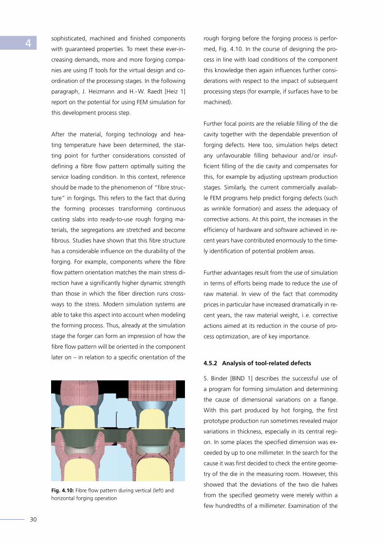
After the material, forging technology and hea-
ting temperature have been determined, the star-
ting point for further considerations consisted of
defining a fibre flow pattern optimally suiting the
service loading condition. In this context, reference
should be made to the phenomenon of “fibre struc-
ture” in forgings. This refers to the fact that during
the forming processes transforming continuous
casting slabs into ready-to-use rough forging ma-
terials, the segregations are stretched and become
fibrous. Studies have shown that this fibre structure
has a considerable influence on the durability of the
forging. For example, components where the fibre
flow pattern orientation matches the main stress di-
rection have a significantly higher dynamic strength
than those in which the fiber direction runs cross-
ways to the stress. Modern simulation systems are
able to take this aspect into account when modeling
the forming process. Thus, already at the simulation
stage the forger can form an impression of how the
fibre flow pattern will be oriented in the component
later on – in relation to a specific orientation of the
rough forging before the forging process is perfor-
med, Fig. 4.10. In the course of designing the pro-
cess in line with load conditions of the component
this knowledge then again influences further consi-
derations with respect to the impact of subsequent
processing steps (for example, if surfaces have to be
machined).
Further focal points are the reliable filling of the die
cavity together with the dependable prevention of
forging defects. Here too, simulation helps detect
any unfavourable filling behaviour and / or insuf-
ficient filling of the die cavity and compensates for
this, for example by adjusting upstream production
stages. Similarly, the current commercially availab-
le FEM programs help predict forging defects (such
as wrinkle formation) and assess the adequacy of
corrective actions. At this point, the increases in the
efficiency of hardware and software achieved in re-
cent years have contributed enormously to the time-
ly identification of potential problem areas.
Further advantages result from the use of simulation
in terms of efforts being made to reduce the use of
raw material. In view of the fact that commodity
prices in particular have increased dramatically in re-
cent years, the raw material weight, i. e. corrective
actions aimed at its reduction in the course of pro-
cess optimization, are of key importance.
4.5.2 Analysis of tool-related defects
S. Binder [BIND 1] describes the successful use of
a program for forming simulation and determining
the cause of dimensional variations on a flange.
With this part produced by hot forging, the first
prototype production run sometimes revealed major
variations in thickness, especially in its central regi-
on. In some places the specified dimension was ex-
ceeded by up to one millimeter. In the search for the
cause it was first decided to check the entire geome-
try of the die in the measuring room. However, this
showed that the deviations of the two die halves
from the specified geometry were merely within a
few hundredths of a millimeter. Examination of the
Fig. 4.10: Fibre flow pattern during vertical (left) and horizontal forging operation
4

31
Fig. 4.11: Only with the help of expanded simulation was it evident that tool deformations resulting from classic springback effects occurred during the forging process
thermal effects on the shrinkage behaviour did not
reveal any signifi cant differences as well.
In the next step, a simulation was carried out which
focused not only on analysis of mass fl ows, but
also included the tool load, Fig. 4.11, since a pos-
sible “dodging“ of the tools was suspected. With
the help of this advanced simulation, it was quickly
found that the forming process led to tool defor-
mations caused by classic springback mechanisms.
In this particular case, this not only involved one die
half being bent: but compression of the core of up-
per die, fi g. 4.12, by up to one millimeter in the
forging process. This was not a permanent plastic
deformation, but was caused by an elastic reaction,
with the tools returning to their original shape again
after each stroke. Once this had been recognized,
simulation helped in designing appropriate cor-
rections to the tool geometry. After tests with the
corrected tools provided positive results, the project
could be released for series production.
4.5.3 Trimming / punching
and coining / sizing
H.- J. Britzger et al. [BRIT 1] report on the motiva-
tion for performing calculations in the fi eld of the
punching / trimming and coining / calibration pro-
cess steps. In hot forging processes these opera-
tions usually take place immediately after the last
main forming step. Trimming differs from punching
in the way that removal of excess material (i. e.
fl ash) is performed beyond the active geometry of
the part.
To do this, the component is forced through a cut
plate by means of a punch. Punching, by contrast,
involves the removal of excess material from the in-
terior of the component using a cutting punch.
Simulation of trimming / punching has now been
included in the standard repertoire of forging si-
mulation. Basically, from the viewpoint of simulati-
on the same boundary conditions apply as to the
“separation“ process step described in section 4.3.
Furthermore, simulation of these operations can
be expected to be relatively complex. Nevertheless,
the trimming / punching operations are more impor-
tant than cut-off as these fi nal forming operations
may result in undesirable deformation of the com-
ponents. This in turn can lead to deviations from
specifi ed tolerances causing unwanted mechanical
post-processing or even non-correctable geometric
defects. In these cases, simulation enables the de-
signer to reduce problems typical of these process
steps as early as the design phase. Furthermore, si-
mulation makes a contribution to a better under-
standing of the intervention or operation of tools.
On top of this, the additional expenditure is justifi ed
by the more accurate depiction of the process chain
or several consecutive parts thereof. Here, the in-
Fig. 4.12: The main cause of the problem was the core in the upper die, which was compressed by up to one millimeter in the forging process
4

32
crease in accuracy can be attributed to generating
accurate geometries and / or realistic temperature
profi les for calculating follow-up operations. Such
an application case occurs, for example, when ex-
amination of the forming process is followed by an
analysis of the heat treatment, Fig. 4.13.
When coining or sizing, a fundamental distinction
has to be made between forming the workpiece at
forging temperature (warm sizing) or at room tem-
perature (cold sizing). Warm sizing is usually perfor-
med in order to reduce the scatter of measures or
to improve shape and location accuracy, and usu-
ally has no lasting impact on stress distribution in
the workpiece. Cold sizing tends to be performed
on selected surfaces, with the aim of increasing di-
mensional accuracy, surface quality and / or shape
and location accuracy. Due to the local application
of forming forces, sizing often implies high stresses
and noticeable strains on the tools. Furthermore, in-
creases of local strength in the surface area of the
part can be achieved by targeted strain hardening
(which forms part of cold sizing).
The simulation of coining / calibration operations is
performed with a view to obtaining important in-
formation about interactions between the compo-
nent and the tool concept. Here on the one hand
calibration simulation helps ensure the precision of
the fi nal geometry of the workpiece and realizati-
on of extremely fi ne geometric details in advance
on the computer. On the other hand, simulation
allows the forger to signifi cantly enhance the ser-
vice performance of the calibration tools. Further-
more, simulation makes it much easier to estimate
the required strain hardening when locally higher
strengths have to be achieved on the component
surface.
4.6 Machining forged parts
The infl uences on the machinability of forging ma-
terials are manifold. Starting from the conduct of
the heat, they extend through the chemical compo-
sition and the forming process up to the heat treat-
ment. Evaluating the machinability of a material is
often based on the criteria of “tool wear“, “cutting
forces“, “chip shape“ and “surface quality“.
Companies in the forging sector do not usually con-
duct simulation-based studies on the impact of pro-
blems related to chip shape, which are very diffi cult
to infl uence. Instead, such evaluations are carried
out on a practical basis (e. g. assessment of different
so-called “chip breakers“). Conversely, the evaluati-
on of different clamping and stop concepts is indeed
the subject of simulation-based analysis – according
to G. Triesch et al. [TRI 1]. This is typically performed
Abbildung 4.13: Simulation of the trimming process as starting point for a subsequent thermal computation
Temperature / °C
4

33
by evaluating the deformation of components using
different clamping systems and / or forces, 4.14.
Furthermore, forgings are distinguished by their out-
standing dynamic component properties – among
other characteristics. At this point, in addition to the
component strength and the setting of fi bre orien-
tation, the residual stresses the component inside or
on the component surface after machining are also
of particular importance. The success of different
measures again can be evaluated using simulation
methods. Thus, for example, the infl uence of diffe-
rent temperature profi les in the component during
forming and possibly of the machining operations
on heat treatment results can be evaluated quali-
tatively.
4.7 Heat Treatment
In the past years, with respect to comprehension
of interactions between boundary conditions and
material properties, in the fi eld of heat treatment
considerable progress has been made. Concurrent-
ly commercial software adapted for simulation of
operations within the respective scope have availed
themselves from the extended state of knowledge
– as per K. Heeß et al. [HEES 1]. For process deve-
lopments in the fi eld of heat treatment, these ad-
vances open up the possibility in future of already
making initial assessments for process management
on the simulation computer. Furthermore, realistic
input parameters offer considerable potential in
the fi eld of process optimization. Simulation is ge-
nerally suitable for indicating trends, for parametric
studies and impact analyses, as well as for signifi -
cantly improving understanding of the closely linked
processes occurring during heat treatment. For this
purpose the temporal and spatial development of
temperatures, structural transformations, deforma-
tions and stresses, as well as interactions occurring
in these processes, have to be determined mathe-
matically in order to proceed to numerical simulati-
on, as illustrated schematically in Fig. 4.15, based on
the example of hardening steel components.
4.7.1 Hardening and tempering
O. Oehler [Oehl 1] reports on the use of simulation in
the context of identifying weaknesses in the design
of a hardening and tempering process. Here parti-
cular attention was paid to the “hardening“ process
step. With this in mind, the behaviour of a cold ex-
truded component during quenching in oil was stu-
died as some parts failed due to quench stress cra-
cking. The evaluation of simulation results revealed
that the cooling rate of the component is highest at
its thinnest cross-section, thus locally falling below
the martensite start temperature. This resulted in a
largely martensitic transformation of the microstruc-
ture in this area – while the remaining part of the
component was markedly austenitic. At the same
Fig. 4.14: Infl uence of the clamping concept on the deformation of delicate components during machining
High
Low
Fig. 4.15: Input and output data as well as interacting partial processes during the simulation of heat treatment processes
Geometry
Microstructure / Hardness
Material
Deviation of measure and shape
Heat treatment
Residual stress
Temperature
Transformation of the microstructure
Deformation / stress
High
Low
Evaluation of global deformation
von Mises effective stress
4

34
time, as a result of the volume jump caused by the
transformation of austenite to martensite, tensile
stresses (> 260 MPa) could be observed at the junc-
tion of this section to a much larger cross-sectional
area, see Fig. 4.16. These tensions were considered
to be critical, especially since they occurred at tem-
peratures of approximately 340 °C (martensite start
temperature “Ms“). The stress gradients occurring
in this critical area were mitigated by geometrically
adjusting the cross-sectional transitions, resulting in
a substantial reduction of the reject ratio. For variant
parts these fi ndings could be included in the com-
ponent design.
4.7.2 Case hardening
O. Oehler [OEHL 2], M. Herrmann and M. Fiderer
[HERR 1] write about a specifi c application of simula-
tion to case hardening – in the course of manufactu-
ring input hubs for dual-clutch transmissions. In this
case the focus was on precision-formed teeth as the
central element of the component. These are sub-
jected to a quenching process in the course of case
hardening treatment. The problem was that after
this process step the parts exhibited a deviation from
the intended geometry of about 25 microns (nega-
tive crowning detected by two-ball testing) over the
entire gearing length. In a fi rst attempt, no satisfac-
tory cure could be achieved despite several practical
tests in the form of variations of the heat treatment.
In connection with subsequent investigations by si-
mulation, the analysis focused on developing an im-
Fig. 4.16: Failure location (a), temperature distribution (b), martensite share (c), 1st main normal stress (d) and effective stress (e) during quenching
Stress – Max principal
Process time 22.9 s
1,000
888
775
663
550
438
325
213
100
150
125
100
75,0
50
25
0.0
-25.0
-50.0
0.661
0.579
0.496
0.413
0.331
0.248
0.165
0.0827
0.000
0.01000
0.00875
0.00750
0.00625
0.00500
0.00375
0.00250
0.00125
0.000
Temperature / °C
Stress / MPa
Volume fraction - (AISI 4140) Martensite
Strain-Effective / mm
259 Min.
643 Max.
-193 Min.
262 Max.
0.000 Min.
0.661 Max.
0.000 Min.
0.01907 Max.
b)
d)
c)
e)
a)
4

35
proved understanding of the processg. In turn, new
solution approaches were generated on this basis. In
order to achieve a virtual representation of what was
going on in the component, metal forming and heat
treatment simulation had to be linked up. The essen-
tial characteristic of this operation comprised passing
on residual stresses stemming from the “gearing by
pressing“ process step and initializing the deformati-
on ratio after reaching the austenitizing temperature.
Finally, it is worth mentioning that component hard-
ness is often used to assess the quality of simulation
results in the fi eld of heat treatment: in the case pre-
sented here, a good coincidence was identifi ed bet-
ween the hardness profi le actually measured and the
visualized curve established by the simulation, see
Fig. 4.17.
4.7.3 Induction hardening
The induction hardening of a crankshaft has been
investigated by D. Cardinaux et al. [CARD 1]. In
practice the intention is to achieve a predefi ned gra-
dient of mechanical properties within the workpiece
by means of local inductive heating with subsequent
quenching in water. This hardens the surface of the
component in the desired areas to a pre-defi ned
depth. The results are improved service characteris-
tics in terms of fatigue strength and wear.
The process is modeled in two stages. The fi rst stage
involves the induction heating of the component to
complete austenitization of the desired areas. The
second stage of modeling concerns the quenching
process.
In the course of developing a suitable fi nite element
model to describe local quenching, numerous cou-
pled physical processes in the fi elds of electroma-
gnetism, heat conduction, mechanical properties
and metallurgical processes have to be taken into
account.
After suitable mathematical models had been set
up, spatial discretization and time integration had to
Case hardening depth (CHD) test according to DIN EN ISO 2639
800
700
600
500
400
300
Hardness / HV
641
612
583
553
524
494
465
436
406
650
604
558
511
465
419
0.1 0.3 0.5 0.7 0.9 1.1 1.3 1.5 mm
0.00 0.815 1.63 2.45 3.26 4.08
Distance / mm
Distance / mm
550 HV
CHD = 1,16 mm
CHD = 1,48 mm
Case hardening, Time 3e + 04s
(0,000; 631)
— data 1
Fig. 4.17: Comparison of the Case Hardening Depth (CHD) computed by simulation (lower diagram) with experimental results (upper diagram)
406 Min.
641 Max.
Har
dn
ess /
HV
Har
dn
ess /
HV
Hardness / HV
641
612
583
553
524
494
465
436
406
0.1 0.3 0.5 0.7 0.9 1.1 1.3 1.5 mm
0.00 0.815 1.63 2.45 3.26 4.08
CHD = 1,16 mmCHD = 1,16 mmCHD = 1,16 mmCHD = 1,16 mmCHD = 1,16 mmCHD = 1,16 mm
406 Min.
641 Max.
Measuring line
4
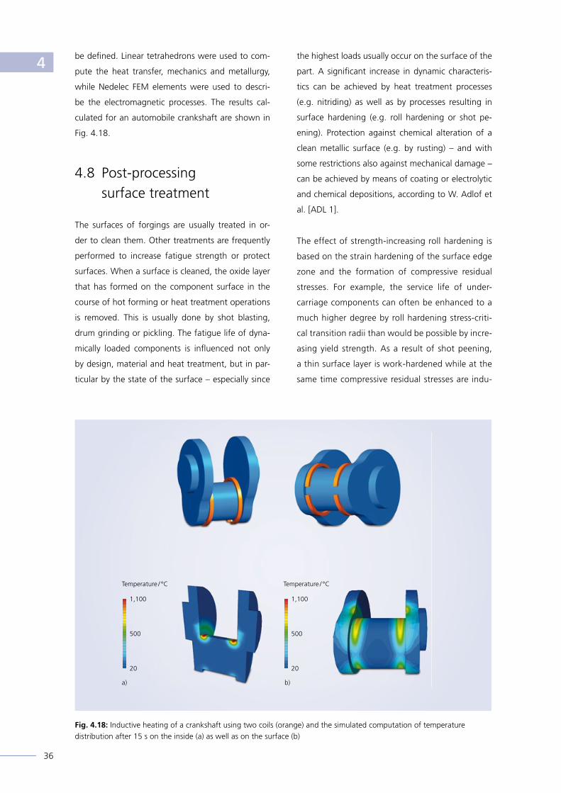
36
be defi ned. Linear tetrahedrons were used to com-
pute the heat transfer, mechanics and metallurgy,
while Nedelec FEM elements were used to descri-
be the electromagnetic processes. The results cal-
culated for an automobile crankshaft are shown in
Fig. 4.18.
4.8 Post-processing surface treatment
The surfaces of forgings are usually treated in or-
der to clean them. Other treatments are frequently
performed to increase fatigue strength or protect
surfaces. When a surface is cleaned, the oxide layer
that has formed on the component surface in the
course of hot forming or heat treatment operations
is removed. This is usually done by shot blasting,
drum grinding or pickling. The fatigue life of dyna-
mically loaded components is infl uenced not only
by design, material and heat treatment, but in par-
ticular by the state of the surface – especially since
the highest loads usually occur on the surface of the
part. A signifi cant increase in dynamic characteris-
tics can be achieved by heat treatment processes
(e.g. nitriding) as well as by processes resulting in
surface hardening (e.g. roll hardening or shot pe-
ening). Protection against chemical alteration of a
clean metallic surface (e.g. by rusting) – and with
some restrictions also against mechanical damage –
can be achieved by means of coating or electrolytic
and chemical depositions, according to W. Adlof et
al. [ADL 1].
The effect of strength-increasing roll hardening is
based on the strain hardening of the surface edge
zone and the formation of compressive residual
stresses. For example, the service life of under-
carriage components can often be enhanced to a
much higher degree by roll hardening stress-criti-
cal transition radii than would be possible by incre-
asing yield strength. As a result of shot peening,
a thin surface layer is work-hardened while at the
same time compressive residual stresses are indu-
Fig. 4.18: Inductive heating of a crankshaft using two coils (orange) and the simulated computation of temperature distribution after 15 s on the inside (a) as well as on the surface (b)
1,100
500
20
1,100
500
20
a) b)
Temperature / °C Temperature / °C
4

37
ced. The impact of various parameter settings for
applying these strength-enhancing mechanisms is
often studied by means of simulation, Fig. 4.19.
During surface rolling, for example, the contact
pressure of the rolling tool or the spacing between
the overrun lines is varied – according to J. Heiz-
mann [HEIZ 2].
Fig. 4.19: Infl uence of diameter and impact velocity of shot grains on the stress distribution of the surface
Tension
Compression
1st principal stress 4

38
Advances in the fi eld of simulation
5.1 Development trends
Authors from among providers of related software
solutions are paying particular attention to ongoing
developments in the fi eld of simulation in forging
[WOHL-2], [PERE 1], [DUCL1], [WALT 1], [DOKT 1],
[TWIC 1], [VLAS 1]. The following paragraphs are
intended to provide a summary of the main trends
in this fi eld. The main requirements of the market
to be met by providers of simulation software are
above all:
• improved accuracy of the results,
• modeling of the interaction between
tool and machine,
• simulation of the entire process chain,
• prediction of component properties based
on models of microstructure development,
• minimization of computing time,
• automatic optimization of manufacturing
concepts,
• use of expert systems.
5.1.1 Improved accuracy of calculation results
One of the top priorities for all software developers
is to improve the quality of the results of FEM cal-
culations. Among other things, this involves bet-
ter element formulations as well as the revision of
physical models describing the process parameters.
Moreover, new approaches to the development of
failure mechanisms – with respect to tools as well
as workpieces – are in the making. Furthermore, a
great deal of attention is being paid to the processes
taking place in the “interaction interstice“ between
workpiece and tool with the aim of modeling the
corresponding tribological system and optimizing it
through simulation.
5.1.2 Modeling the interaction
between tools and machine
Another fi eld of considerable interest is work aimed
at extending forming simulation by adding models
that allow for the interaction between forming ma-
chine and tool. A major aspect in this context is
the consistent consideration of elastic effects in the
process as they have a signifi cant impact. Overall
elasticity comprises the elasticities of the workpi-
ece, the tools and the machine. While inclusion of
the former can now be considered standard, so far
the modeling of elastic tools has turned out to be
much more challenging in practice – at least in 3D.
The main reasons for this are the complex simula-
tion models with their “multi-body contact“ both
between the workpiece and tooling and between
the individual components of the tool – especially
in the case of demanding tools reinforced by shrin-
kage rings, as used in cold forming, for example.
The main obstacles for a wider application are ext-
remely long computation times and signifi cant chal-
lenges with respect to the numerical stability of the
models. The situation is further aggravated by the
fact that for a highly accurate simulation result it is
often necessary to realistically depict springs as op-
Fig. 5.1: Horizontal deformation of the frame of a forging press resulting from an eccentric position of the die
-0.007955 Min.
0.01833 Max.
dispX
0.018
0.016
0.012
0.01
0.008
0.006
0.004
0.002
0
-0.002
-0.004
-0.006
5

39
tional tool assembly elements within the simulation
model. For this task it is important that the mode-
ling of all variants of different types of springs and
spring concepts is made as user-friendly as possible.
Another critical factor is still consideration of the
elasticity of the whole machine (Fig. 5.1), especially
in the case of multi-stage presses, where tilting be-
haviour also has to be depicted. Different models
are available for this purpose, which are generally
described as replacement spring stiffnesses. Prob-
lems here relate in particular to defi ning the para-
meters necessary to describe the behaviour of the
respective machine (e. g. tilting stiffness) or their
supply by the machine manufacturer. Furthermore,
software houses are also working on the inclusion
of guiding clearances, e. g. between ram and cross-
head guiding.
An important step towards the realistic depiction of
machine behaviour is also the correct representation
of the kinematics, which, as experience shows, has
a signifi cant impact on the quality of the result of a
process simulation. Whereas in the past the descrip-
tion of the kinematics partly still involved some ex-
treme simplifi cations, nowadays numerous kinema-
tics can be depicted with a good level of accuracy.
Today powerful simulation systems even include the
process-dependent control of production, e. g. for
ring rolling or open-die and radial forging.
5.1.3 Simulation of the entire process chain
Integration of the individual simulations of various
manufacturing processes along the process chain is
one of the main demands of the market. This invol-
ves handing over the process-related characteristics
of a production operation to the next process step.
For example, the data of a component strengthe-
ned by cold-working can be handed over to a fi nal
structural analysis. Another example is the simulati-
on of an open-die forging process, which builds on
the results of a casting simulation performed during
production of the forging billet, and whose data will
in turn be made available to the downstream ma-
chining and fi nal heat treatment operations. Such
simulations are also of interest when it comes to
assessing the effects of residual stresses induced by
forging and heat treatment on the deformation of
the component after machining, Fig. 5.2).
Simulating complete process chains still poses se-
veral challenges. For example, data and parameters
must be passed on from one simulation model to
the next, which requires the use of powerful map-
ping algorithms. It should be noted that in doing this
the data have to be readapted to sometimes com-
pletely different network topologies as the various
systems for process simulation – such as forming,
welding, crash testing or structural analysis – often
Fig. 5.2: Deformation of a forged disk during the broaching of slots in the wheel face. The stress fi elds and thus the deformation patterns change with each machining pass
5

40
use completely different networks and element ty-
pes. Another problem arises from the question as to
which data should be selected for transfer, i. e. what
relevance they have for the next process step. Here
software developers still face numerous challenges.
5.1.4 Predicting component properties
Apart from the classic result sets of forming simula-
tion, such as material fl ow, force requirements, dis-
tribution of stresses and the degree of deformation,
as well as stressing on the tool, users are increasing-
ly focussing on the actual prediction of component
properties.
Special emphasis is put on mechanical properties
such as the distribution of hardness and strength
through to notch impact toughness or fatigue
strength. Ultimately, these properties can be attribu-
ted to the structural composition and the distribu-
tion of the various metallurgical phases within the
component, implying that these specifi cations also
have to be computed both in the course of simu-
lating the forming process and during subsequent
heat treatment. This in turn requires modeling at
a microscopic level, allowing for mechanisms such
Fig. 5.4: Quantitative microstructure chart of a NiCrMo steel with 0.27 % Cr and 2.5 % Ni
Fig 5.3: The distribution of grain sizes in the forging analyzed on the basis of the simulated dislocation density
14.73
13.79
12.85
10.91
8.897
7.703
6.509
5.315
4.121
3.073
2.267
1.461
1.517 Min.
14.88 Max.
Austenite grain size / µm
%
s
Microstructure / Hardness in depending on
Evolution of value
Strength / MPa: 1579.2
Ferrite 0 %Pearlite 0 %
Martensite 96.47 %
FerritePearliteBainiteMartensiteStrength
Bai
nite
, Fer
rite,
Mar
tens
ite, P
earli
te
Strength [M
Pa]
Hardness [HV] 519.5 / Bainite 3.5 % / Ferrite 0.0. % / Martensite96.5 % / Pearlite 0.0 %
5

41
as dislocation reactions, recrystallization, precipita-
tion formation and microstructural transformation.
Structure models already exist for the simulation
of dynamic and static recrystallization and a great
deal of work is being done to develop them further,
Fig. 5.3. In the case of hot forging, this determi-
nation of the crystalline structure and the related
properties by means of simulation already has a lon-
ger tradition, for example in the open-die forging
of large generator shafts, where simulation of the
phase transition based on TTT diagrams is already
established.
Other approaches are based on modeling by means
of neural networks, which fi rst have to be trained
after their confi guration. Upon successful comple-
tion of this phase it becomes possible to estimate
the expected microstructure of various steel com-
positions within a very short time, Fig. 5.4. Even in-
homogeneities, such as those occurring in forging
ingots, could be considered locally.
5.1.5 Minimizing computation times
Computation times still remain a critical factor.
While the power of modern computer systems is still
rapidly increasing, the computation requirements of
modern simulation tools is also soaring as a result
of growing demands with respect to performance
bandwidth and the quality of results. Both factors
tend to balance each other out.
The most important step to counter this stalema-
te has proved to be increasing the computational
speed by parallelization of computational models so
that several computers can work in parallel on the
same model, Fig. 5.5. This approach, which has long
since proved its merits in the fi eld of structural ana-
lysis, could only later be used for forging simulation
because the mandatory fully automatic remeshing
it requires makes parallelizing much more diffi cult.
In the area of actual forging simulation this strategy
is now de facto state of the art. Nevertheless, soft-
ware houses are still trying to enhance the speed
and fl exibility of the related strategies and mathe-
matical models and to further increase the number
of processors that can be used in parallel. “Paral-
lel computing“ of complex models, including the
tools, holds major potential, Fig. 5.6. In such cases,
for example, different tool parts may be assigned
to different domains and then either processed on
different CPUs or cores, or themselves parallelized
once again.
5.1.6 Automatic optimization
of manufacturing concepts
Process simulation in manufacturing technology of-
ten comes down to virtual testing with multiple test
cycles. The optimization of development processes
that involve such procedures is the objective of in-
tensive efforts by developers of IT tools for the si-
mulation of forging processes. Up to now, the com-
Fig. 5.5: The more cores, the higher the computational speed. Graphic representation of the speed gain for a 3 stage connecting rod forging simulation
Fig. 5.6: Break-up of a simulation model into several CPU partitions taking into account the linear-elastic characte-ristic of the die blocks
4 cores
CPU time
6 cores 12 cores 24 cores
7.46
h
6.33
h
3.42
h
2.10
h
5

42
puter-assisted automatic optimization of these steps
was precluded by the amount of computation this
required. However, thanks to modern high-powered
computers and the improved performance of the si-
mulation programs, the computing times required
for such approaches are now drawing closer to a
reasonable order of magnitude.
Automated optimization is also intended to increase
the quality and reliability of simulation results. This
can be achieved by minimizing a target function by
means of several automatic simulation calculations
in order to fi nd the optimum for one or more para-
meters.
In this context, an important aim is also to objectify
decisions on design changes in a process or tools,
even for complex forming processes, in order to
avoid risky “gut decisions“. This also makes it ea-
sier to assign such tasks to younger employees with
less experience and also allows for the fact that the
process window limits are becoming ever narrower,
both technologically and with respect to develop-
ment time.
This automatic optimization makes it possible to ad-
apt process parameters such as friction factors to
real process conditions. Furthermore, the task is to
accurately comprehend the material fl ow while at
the same time reducing forming loads and / or dis-
tributing them among the individual forming stages
in a more advantageous manner by modifying tool
radii and tool draft. In addition, automatic optimi-
zation makes it possible to signifi cantly reduce the
weight of the forging billet, thus saving material
and costs, Fig. 5.7.
When automatically modifying tool geometries,
a close tie-in with the existing CAD environment
is vital. Moreover, the description of the shaping
geometry has to lend itself to full parametrization,
which is not necessarily the case for the free-form
surfaces typical of a forging die. Here a lot more
development work is necessary – also by CAD soft-
ware providers.
Fig. 5.8: The cooling curves predicted by simulation are depicted for two locations (left). They differ signifi cantly from the experimental data represented by symbols. After an iterative development of HTCs (Heat Transfer Coeffi cients) simulation and experiment coincide quite neatly (right)
1,900
1,700
1,500
1,300
1,100
900
700
1,900
1,700
1,500
1,300
1,100
900
70020 22 24 26 20 22 24 26
Fig. 5.7: The integrated optimization routine automatically linking simulation software and CAD system makes it possible to reduce the mass of the rough forging by 10 %. The red area depicts the contour of the fl ash before optimization while the result after optimization is shown in blue
D2
Time /s Time /s
Measured data Thermocouple #1 Thermocouple #2
Tem
per
atu
re /
F
Tem
per
atu
re /
F
Simulation with constant HTC — Prognosis – #1— Prognosis – #2
5

43
Another branch of optimization development deals
with determining the thermophysical characteristics
of an alloy required for simulation of the forming
process. In the past this was mostly expensive and
time consuming. In the meantime, simulation tools
for the step-by-step calculation of the heat transfer
coefficient (HTC) using an inverse method have be-
come available. Their starting point is experimentally
determined temperature-time data gained from a real
process using thermocouples. Subsequently, the soft-
ware performs several simulation loops using an opti-
mization routine to determine the HTC (as a function
of temperature). This optimization is iteratively re-
peated until the calculated curve becomes consistent
with the experimentally determined data, Fig. 5.8.
5.1.7 Use of expert systems
The future functionalities of simulation software will
increasingly also include expert systems that go bey-
ond predicting the performance characteristics of
the component with the maximum possible accu-
racy. These are intended to make it easier for staff
to make targeted use of forging simulation. The key
driver of this development is increasing staff fluc-
tuation. As a result of this mobility, factors such as
work experience and the experience of individual
employees, for example with respect to fine-tuning
materials and the related design of the tool, are ten-
ding to decline. The expert system is intended to
compensate for this negative trend. The minimum
requirement for such a system is management of
the history of all simulations conducted in the com-
pany and easy access to these data based on prede-
fined criteria, Fig. 5.9.
The system should be structured according to the
range of component types occurring and should be
able to identify the type of component and provide
suitable proposals concerning the parameters of the
forging process, the rules for the tool concept and
the requirements and boundary conditions for an
optimization.
As a rule, such an expert system is capable of lear-
ning, which means that it constantly expands its
experience by including all new simulations carried
out in the company. For this it requires access to
the new communication systems available today in
order to be used for result analyses or group mee-
tings of simulation experts, for example using tablet
computers.
Fig. 5.9: Input menu of a process database drawing based on the know-how of a software provider
5

44
5.2 Progress in understanding basic principles
Together with software providers and forging com-
panies, many technical and scientifi c institutions,
such as universities, are engaged in developing new
simulation techniques and / or improving existing
ones by participating in numerous research projects.
The current focus is on investigating basic know-
ledge, developing improved models and including
further simulation tools in simulation systems. The
cause-and-effect diagram (Fig. 5.10) highlights the
main emphasis of current development directions in
research projects with regard to the usefulness of
simulation. Selected projects are presented below.
5.2.1 Alloy database using steel alloys
as an example
One prerequisite for the successful simulation of
forming processes is the availability of reliable
data on the thermophysical properties and trans-
formation behaviour of the materials used. These
can be acquired from various useful sources. In the
following chapter, U. Diekmann [DIEK 1, DIEK 2]
presents the example of a steel database main-
tained by the Steel Institute of the VDEh, which
is the offi cial database of the European steel re-
gistry. Alongside references to standards, delivery
conditions, product forms and manufacturers, it
especially contains technical data sets acquired
from material testing. The database offers search,
visualization and analysis capabilities. In addition
to the usual information such as material number,
chemical composition and mechanical properties,
the system also provides temperature-dependent
properties in conformity with SEW 310 for about
450 materials, as well as links to other data sets,
such as TTT / TTA charts, metal sheet specifi cations
and the forming fl ow curves that are indispensable
for forming simulation, Fig. 5.11.
Fig. 5.10: Major development paths of research projects in the fi eld of scientifi c and technical institutions
Design / optimization of forging processes
Component design/ - optimization
Design/ optimization of tooling systems
Material development
Process mastery; Savings in costs and time; Prediction of of component properties
Eliminiation of forging defects
Design of forging stages
Selection of press
Defi nition and optimization of process parameters
Transport optimization
Material reactions Component properties
Prediction of workpiece damage
Optimal workpiece shape
Weight savings
Depiction of material behaviour
Development of higher strength steels
Virtual material development
Minimization of wear and tear
Prediction of crack formation
Prediction of tool performance
Simulation
Benefi ts of forging simulation
5

45
To complement this, a software package (even here
there are different systems) makes it possible to cal-
culate material properties as a function of chemical
composition and process control. Using a well-es-
tablished thermodynamic basis (CalPhaD), the soft-
ware features different models for the calculation of
material properties such as thermophysical data. For
the generation of data sets, such as the TTT diagram
shown here, (Fig. 5.12), the models use a physical
basis. The material properties computed are used
especially in the FE simulation of casting, forming
and heat treatment processes.
5.2.2 Infl uence of the heating rate on the
formability of steel and aluminium
For metallic alloys, fast heating or reheating can lead
to inhomogeneities in the microstructure and thus
to divergences of the microstructural state from that
of the thermodynamic equilibrium. The microstruc-
tural state and grain size for different heating rates
during the austenitizing of steel can be determined
using a time-temperature austenitizing diagram
(Fig. 5.13). High heating rates (e. g. 20 K / s or
41 K / s) above the transition temperature Ac3 may
result in a microstructure whose austenite grains are
inhomogeneously enriched with carbon. Conversely,
a slowly heated microstructure (e. g. 1 K / s) usually
consists of largely homogenized austenite. Further-
more, with increasing holding time progressive grain
growth can be expected.
Recent investigations by R. Kawalla and G. Korpala
[KAWA 1], which focused on the infl uence of diffe-
rent heating methods and heating rates on the form-
ability of steel (20MnCr6, 40CrMo5 and 100Cr6)
and aluminium (AlSiMgMn), aimed at exploring the
applicability limits of standard stress strain curves to
simulate forming processes. Both fast inductive and
conductive and slow convective heating technolo-
gies were compared.
As expected, a strong dependence of the measured
yield stress on the heating rate was recorded in all
materials. For the steels examined, for example, a si-
gnifi cantly higher fl ow resistance could be identifi ed
if heating to a forming temperature of 850 °C had
been performed rapidly (as compared to slow hea-
ting). Further analyses can be expected following
discussion of the results presented here.
5.2.3 Alloy and process design using thermo-
dynamics and microstructure modeling
In the fi eld of hot forging of steels, deformation,
temperature profi le and development of the mi-
crostructure are usually subjected to substantial in-
teractions. In currently available approaches to the
modeling of steel forming, as a rule only limited
attention is paid to this phenomenon. As part of
the research performed by L. Mosecker [MOSE 1]
and K. Schacht [SCHA 1] at the Institute of Ferrous
Metallurgy, RWTH Aachen, a metal physical model
140
120
100
80
60
40
20
0
900
800
700
600
500
400
300
2000.0 0.4 0.8 1.2 1.6 0.1 10 1,000 100,000
Flow curve model
Equivalent plastic strain / -
Gra
in s
ize:
8.4
AST
MA
uste
nitis
atio
n: 9
00 °
C
— Ferrite 0.1 % Pearlite 0.1 % Bainite 0.1 %
Pearlite 99.9 % Bainite 99.9 %
Time / s
Flo
w S
tres
s / M
Pa
Tem
per
atu
re /
°C
Fig. 5.11: Examples of a hot fl ow curve for a steel Fig. 5.12: A TTT diagram of a heat-treatable steel computed using the software
5

46
has been developed to improve depiction of local
fl ow properties, Fig. 5.14. The investigation focused
on microalloyed forging steels such as precipitation-
hardening ferritic-pearlitic (AFP) steels.
The introduction of internal structural variables (such
as dislocation density) make it possible to describe
metal physical phenomena such as recovery and re-
crystallization, as well as precipitation behaviour and
grain growth on the basis of empirical approaches
and to quantify their infl uence on the mechanical
behaviour. The core of the material model is a ma-
thematical description of the evolution of dislocation
density. This in turn is used to compute static and dy-
namic recrystallization and calculate precipitations.
The microstructure-based approach is expected to
permit improved simulation of material fl ows (e. g.
for predicting possible forging defects) as well as
a prognosis with respect to the state of the mi-
crostructure. At this stage, the phase transformation
to ferrite and pearlite occurring after forging is not
yet depicted. Current investigations relate to linking
the microstructure model with the thermodynamic
description of the development of precipitations. In
this context, the infl uence of various micro-alloying
element (MLE) systems on material behaviour is de-
scribed as a function of dislocation density and the
type and mass fraction of MLE. Another aim is to
formulate a dependence on the chemical compositi-
on for as many model parameters as possible of the
approach so far formulated. Here use is made of the
absolute melting temperature, which in turn can be
predicted by means of thermodynamic databases.
Furthermore, the integration of billet-reheat contri-
butes to the development of a continuous virtual
process chain.
5.2.4 Robustness of the modeling
of microstructures when designing
a drop forging process
Within the framework of ongoing research at the
Institute of Bildsame Formgebung (IBF) of the RWTH
Aachen University, T. Henke et al. [Henk 1] focused
on developing statistical methods to quantify varia-
tions in material behaviour, as they arise, for examp-
le, due to batch variations and inhomogeneities,
and their inclusion in microstructure-based material
models. The background motivation for this work
was the desire to be able to make predictions with
respect to the robustness of the subsequent produc-
tion process, in addition to the integrative predic-
tion of process parameters and product properties.
For this reason, statistical methods are increasingly
1,000
900
800
700
600
320 µm80 µm40 µm20 µm
14 µm
10 µm
7 µm5 µm
0.1 1 10 100 1,000 10,000 100,000
Time / s
Tem
per
atu
re /
°C
Fig. 5.13: Example of a time-temperature austenitization (TTA) diagram of a steel for different heating rates. The red and black dots indicate different initial states of the forming process at the same temperature
Ac3
Ac1 e
Ac1 s
41 K / s 20 K / s Conventional; 1 K / s
Heating rate:
inhomogeneous Austenite
homogeneous Austenite
Grain size5

47
being used in process design. However, every ro-
bustness analysis requires knowledge of the varia-
tions in the input data of the model used for the
design, but these variations are usually estimated
since they are hard to measure.
In the design of metal forming processes, the beha-
viour of the material has a major impact on the pro-
cess parameters and the properties of the product.
Simulation models describing the behaviour of the
material are therefore increasingly selected in view
of their aptness for integratively depicting fl ow pro-
perties and the development of the microstructure.
For this purpose, with the aid of a modular material
model developed at the IBF, both physical, disloca-
tion-density-based and semi-empirical approaches
to the description of hardening and softening as a
result of recovery and recrystallization can be com-
bined almost at will.
The statistical methods now developed at the IBF to
take material variations into account are based on
the so-called “re-sampling“ method. Using such a
material model to describe fl uctuations when desig-
ning a drop forging process for the production of a
bevel gear from a microalloyed steel 25MoCr4-Nb-
Ti, it was possible to predict the variations of the
microstructure scatter that could be expected in the
real process in distribution functions. Conversely, a
comparison with the microstructure distribution of
gears actually produced (Fig. 5.15) showed that if
a conventional non-fl uctuation-adapted model is
used, this may result in underestimating the real
grain sizes. The confi dence limits of the calculated
distribution functions on the other hand reliably in-
cluded the grain sizes of the experiment.
5.2.5 Modeling the friction
between workpiece and tool
The feasibility and the force and energy requirements
of the forming process critically depend, above all,
on the ability of the tribological system to keep tool
and workpiece separate in the course of the forming
process and to maintain good lubrication in order to
minimize wear resulting from shear forces.
Fig. 5.14: Logical link-up of the different modules for a microstructure-based computation of multi-stage forming processes
Temperature, Strain rate, Grain size,
Chem. composition
Temperature, Strain rate, Grain size,
Chem. composition
Critical dislocation density
ρcrit
Precipitation model
Y/ N
Evolution of dislocation density /
Dynamic recrystallization
Evolution of dislocation density /Static recrystallization
fconv
ρcrit
kdyn1c83c11nσ
CVFv; R
ρ
CC
Dm
CN
x Dn ρm
kstat
Temperature, Strain rate, Grain size,
Chem. composition
5

48
At the same time, the quality of a fi nite element
analysis largely depends on the accuracy of the fric-
tion model describing the tribological interactions
between the workpiece and the forming tools.
Alongside a number of other institutions, the Insti-
tut für Produktionstechnik und Umformmaschinen
(PtU) of the Technische Universität Darmstadt and
the Institut für Umformtechnik und Umformma-
schinen (IFUM) at the Leibniz Universität Hannover
conduct research aimed at infl uencing and mode-
ling the friction between workpiece and tool during
forging processes.
In order to improve the quality of FEM simulations,
the Department of Tribology and Surface Technolo-
gy of the PtU recently examined a new, optimized
modeling of friction in the cold-forming process.
To this end, Stahlmann et al. [STAH 1] and Ludwig
et al. [LUDW 1] developed a new approach. It de-
scribes the changes in the workpiece surface in the
course of cold forming and includes fi eld variables
with a signifi cant infl uence on friction behaviour.
They found that the friction coeffi cient depends
not only on the normal contact stress but also on
the surface enlargement. Furthermore, the model
takes the load dependence of the workpiece sur-
face structure into account. A tribometer for cold
forming – the compression-sliding plant (Fig. 5.16)
– is used to determine the friction coeffi cient.
As changes of the contact area between the friction
partners are taken into account, the results provide
information on tribological loads in forming proces-
ses. Using these models meant that it was possi-
ble to determine the relationship between surface
roughness and variables describing the surface sta-
te. The methodology proved to be both economical
with respect to the computational expense for the
simulation as well as promising in terms of predic-
ting the roughness of workpiece surfaces. Further-
more, in future the values for the surface roughness
determined by simulation can be used to determine
frictional characteristics in relation to surface chan-
ges. Better representation of real forging processes
can therefore be expected. Further research at PtU
aims at transferring the results found so far to in-
dustrial practice. In this context, a current shortco-
ming in the model, integration of the tool surface
roughening, will be included in the model descrip-
tion. At the IFUM, B.-A. Behrens et al. [BEHR 1] de-
veloped a new model for friction conditions typical
of hot forming processes. The friction is infl uenced
mainly by the surface condition, the local stress sta-
te and relative sliding velocity. Classic friction mode-
Fig. 5.15: Comparison of simulation with real results of a microstructure analysis
0.3
0.2
0.1
0
0,3
0,2
0,1
010 12 14 16 18 20 12 14 16 18 20
Pro
bab
ility
Pro
bab
ility
Grain size / µm Grain size / µm
97.5 % 97.5 % P1
dy3m = 12.8 µm
P2
dy3m = 14.2 µm
conv. Model
conv. Model
Experiment Experiment
15 mm
50 µm
Fine grain after forging
2
50 µm
Coarse grain before forging
5

49
ling approaches consider the above factors with in-
suffi cient accuracy or even ignore them completely.
In line with existing approaches to friction, the new
friction model is able to differentiate between stress
states with low or high contact pressures and/or
between elastic and plastic deformation. These two
stress states are weighted using the ratio of the effec-
tive stress according to von Mises and the local yield
stress of the workpiece material (σeq / σy), resulting in
a combination of the friction fi gure model according
to Coulomb and the friction factor model according
to Tresca. A signifi cant enhancement of existing fric-
tion approaches is achieved by describing the infl u-
ence of the sliding speed on the friction shear stress.
In the new IFUM model this is performed using an
exponential approach that allows for dynamic friction
effects occurring during lubricated forging processes.
5
4
3
2
1
0
0.00 0.02 0.04 0.06 0.08 0.10 0.12
— Experimental forming force
Simulation with IFUM friction model— C = 150
Simulation with friction factor model— m = 0.2 — m = 0.45 — m = 0.7
Time / s
Form
ing
fo
rce
/ MN
Fig. 5.17: Comparison of force-time curves established by simulation with experimental results
Fig. 5.16: Schematic representation of the compression-sliding system used at the PtU for research into friction ratios between workpiece and tool
Punch
Compression force
Sliding plate
Sample
Frictionstress Sliding operation
Compression
Initial position
5

50
Fig. 5.17 shows a comparison of the numerically ver-
sus experimentally determined force-time curves of a
forming process. The graph confi rms a high correlati-
on of the numerical results between the new friction
model and the experimental data.
The use of the new friction model for the numerical
representation of industrial-scale forging processes
has shown that calculation accuracy can be increa-
sed by means of FE-assisted process simulation. This
has already been implemented in sector-specifi c
commercial FE systems and validated by comparison
with experimental test results.
5.2.6 Coupling of forging simulation with
non-linear forging press models
In multi-stage forming processes, measures for ad-
apting individual forming steps (e.g. fi lling behavi-
our or the degree of fi lling) have a major impact on
the overall result. At the same time, the infl uence
of such individual actions often cannot be clearly
predicted. Fundamental uncertainties arise from the
fact that at present interactions between the blanks
to be formed and/or their intermediate forming
stages, the tool concepts developed for their for-
ming and the selected forging plant have not yet
been fully investigated. In this context, the latter
plays a key role since every press type usually has
its very specifi c load / displacement characteristic.
Furthermore, the respective springback, tilting and
offset characteristics are also infl uenced by the ar-
rangement of the tools on the press table. In practi-
ce – especially when matching up forming stages for
the production of new parts – this regularly results
in increased expenditure and in some cases also in
signifi cant delays.
C. Brecher et al. [BREC 1] focus on the analysis and
modeling of interactions between the workpiece,
the tool and the forming plant, Fig. 5.18. A metho-
dology developed at the Werkzeugmaschinenlabor
(WZL) of the RWTH Aachen in recent years supports
the virtual optimization of single-stage and multi-
stage tools, allowing for the load-displacement
behaviour of the production plant and the selected
tool system. To achieve this, a new software pro-
gram is linked to conventional forging simulation
systems. The tool analytically depicts the machine-
and mold-specifi c spring and tilt stiffness as well as
the translational and rotational allowances of the
forming plant and the tool system, using a non-
linear approach. Based on the processing force pre-
Fig. 5.18: The software developed at the WZL in the context of several research projects takes into account the complex interactions between workpiece, tool and plant and supplies the software used for forming simulation with related corrective values for the part geometry
• Spring back
• Ram tilt
• Horizontal offset
• Kinematic
• Process stress
• Material behaviour
• Friction
• Temperature transition
• Contact conditions
• Tool support guiding (Stiffness, clearance)
• Elastic deformation and stiffness distribution in die, die support and tool support
Machine
Tools
Forging process
Interactions affecting the forging result
5
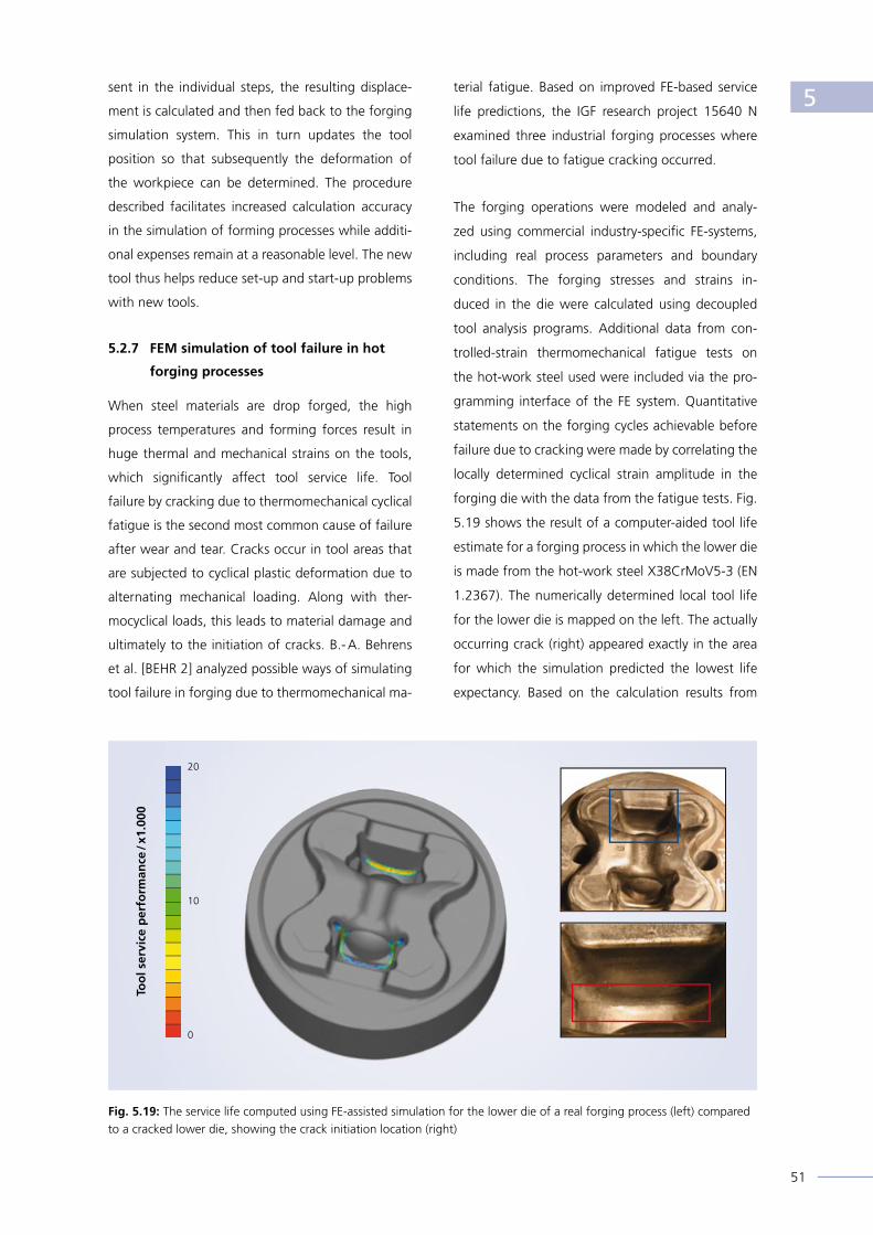
51
sent in the individual steps, the resulting displace-
ment is calculated and then fed back to the forging
simulation system. This in turn updates the tool
position so that subsequently the deformation of
the workpiece can be determined. The procedure
described facilitates increased calculation accuracy
in the simulation of forming processes while additi-
onal expenses remain at a reasonable level. The new
tool thus helps reduce set-up and start-up problems
with new tools.
5.2.7 FEM simulation of tool failure in hot
forging processes
When steel materials are drop forged, the high
process temperatures and forming forces result in
huge thermal and mechanical strains on the tools,
which signifi cantly affect tool service life. Tool
failure by cracking due to thermomechanical cyclical
fatigue is the second most common cause of failure
after wear and tear. Cracks occur in tool areas that
are subjected to cyclical plastic deformation due to
alternating mechanical loading. Along with ther-
mocyclical loads, this leads to material damage and
ultimately to the initiation of cracks. B.- A. Behrens
et al. [BEHR 2] analyzed possible ways of simulating
tool failure in forging due to thermomechanical ma-
terial fatigue. Based on improved FE-based service
life predictions, the IGF research project 15640 N
examined three industrial forging processes where
tool failure due to fatigue cracking occurred.
The forging operations were modeled and analy-
zed using commercial industry-specifi c FE-systems,
including real process parameters and boundary
conditions. The forging stresses and strains in-
duced in the die were calculated using decoupled
tool analysis programs. Additional data from con-
trolled-strain thermomechanical fatigue tests on
the hot-work steel used were included via the pro-
gramming interface of the FE system. Quantitative
statements on the forging cycles achievable before
failure due to cracking were made by correlating the
locally determined cyclical strain amplitude in the
forging die with the data from the fatigue tests. Fig.
5.19 shows the result of a computer-aided tool life
estimate for a forging process in which the lower die
is made from the hot-work steel X38CrMoV5-3 (EN
1.2367). The numerically determined local tool life
for the lower die is mapped on the left. The actually
occurring crack (right) appeared exactly in the area
for which the simulation predicted the lowest life
expectancy. Based on the calculation results from
Fig. 5.19: The service life computed using FE-assisted simulation for the lower die of a real forging process (left) compared to a cracked lower die, showing the crack initiation location (right)
Too
l ser
vice
per
form
ance
/ x1
.000
20
10
0
5

52
the failure simulation, improved and more effi cient
layouts of tooling concepts and forging stages are
possible.
5.2.8 Controlling damage
in cold forging processes
Due to the complexity of modern materials and the
high demands on the fi nished components, advan-
ced simulation methods for accurately predicting the
behaviour of materials in the manufacturing process
and the resulting component properties are indis-
pensable. D. Helm [HELM 1] deals with the modeling
of the mechanisms that can lead to the formation of
internal defects caused by localized transgression of
metal plasticity during forging processes. This makes
it possible, for instance, to integrate aspects such as
quality, cost and process reliability in the develop-
ment process early on, allowing for material-specifi c
formability limits. For example, if unfavourable pro-
cessing parameters are used during cold full-forward
extruding, massive damage in the workpiece in the
form of so-called “chevrons“ can occur (Fig. 5.20).
Their development can be signifi cantly infl uenced by
a suitable design of the forming process.
The objective of research currently being conducted
at the Fraunhofer IWM in Freiburg is to use advan-
ced numerical simulation methods for cold-forming
processes fi rstly to predetermine the development
of defects and, based on the results, to identify sui-
table parameters and / or an optimized tool geomet-
ry to avoid the described defect.
As a starting point, mechanism-based material mo-
dels are used to analyze and optimize metal forming
processes. Based on micromechanics, these model
the physical source of the damage resulting from the
formation, growth and merger of pores. At Fraun-
hofer IWM the problem has been addressed using
a specially refi ned model after Gologanu-Leblond,
which takes into account the infl uence of complex
deformation paths on pore development and pore
shape.
After adjusting the model parameters, it turned out
that the initial state of the deformation process to
be optimized is described correctly. The periodicity
and shape of the “chevrons“ predicted by the si-
mulation accord well with the results of practical
experiments. Furthermore, the model also correctly
depicts two effects known from practice – surface
waviness and a drop in the press force profi le during
formation of the “chevrons“. Further simulation
studies have shown that by changing the tool geo-
metry at a constant degree of taper, the pore density
increases only slightly, thereby effectively avoiding
“chevrons“. Despite these successes for a relatively
simple one-stage forging process, predicting damage
evolution in multi-stage cold forging processes
with complex deformation paths dependent on the
process history is a challenge that requires further
research activities.
5.2.9 Development of holistic approaches
Current trends in the forming processes of metallic
materials include both the forming of lightweight
components and the increase in product diversity.
At the same time, there is a desire to improve ener-
gy effi ciency in production. Likewise, control of the
diverse processes, making them shorter and more
fl exible, as well as integrating them, is taken into
account. Moreover, one exciting challenge for for-
Fig. 5.20: Formation of “chevron cracks“: experiment (above) and computed pore density (red = high, blue = low) before (picture at centre) and after optimizing the tool geometry (below) during full-forward extruding
5

53
ming technology comprises not only predicting pro-
duct quality, but also controlling development of the
microstructure. One of the focal points of research
work undertaken at the Institut für Umformtechnik
und Leichtbau (IUL) is to develop a method for tack-
ling the different tasks occurring during the deve-
lopment phase of forming processes, [SOYA 1]. This
method is based on sophisticated and at the same
time effi cient numerical models representing the
material behaviour and is based on a holistic fi nite-
element approach. The area of investigation extends
from analyzing multi-stage sheet forming, forging
and sheet forging processes to predicting product
features, including the assessment of crash behavi-
our and service life. The requirements arising from a
model or platform change are overcome by making
specifi c use of sophisticated physical material mo-
dels realistically describing local changes in the state
of the material. Typically this involves considering
solidifi cation behaviour, the cumulation of defects
or changes in textures. This makes it possible to use
standardized models for different forming processes.
Furthermore, the remaining formability of the mate-
rial can be estimated, and intended (or unintended)
material separations (e.g. cutting, shearing or pun-
ching operations) can be modeled, see Fig. 5.21. In
addition, the accurate prediction of product cha-
racteristics – such as strength or zones with critical
defect accumulation – becomes possible, following
the product development process. These data are
in turn available as input values for predicting crash
behaviour and service life. Each characteristic can
Fig. 5.21: Research performed at the IUL to simulate defect evolution during different sheet forming, forging and sheet forging processes using a holistic model approach
Parting fracture
Shear fracture
(Sheet), tensile test Upsetting
Deep-drawing
ExtrusionNakajima test
Sheet forging
Punching
Planar torsion test
Deep-drawing
Bending
Tensile test with notched specimens
Mixed fracture mode
5

54
be specifically set if it has initially been defined as
a target value for the design process. In order to
verify this holistic approach, the IUF conducts expe-
rimental studies. The respective material properties
are characterized on this basis. This is done in order
to optimize existing manufacturing processes or to
develop new processes. In the course of this work,
the development of previously unavailable or only
vaguely defined interfaces between the simulation
of multi-stage forming processes, the prediction of
product features and the product service life is con-
tinuously advanced.
5

55
Economic Aspects
In the course of a survey conducted among mem-
ber companies of the Industrieverband Massivum-
formung e. V. (IMU, German Forging Association),
H. Ade and J. Heizmann [UMFR 1] went into the
question as to what benefi t the companies in the
sector attribute to the programs they use to simu-
late forging processes. For this purpose, a question-
naire on monetarily and non-monetarily assessable
aspects of the software application was developed.
This survey provided an overview of the application
of forming simulation software within the German
forging sector. Furthermore, participants were of-
fered the prospect that this feedback would make
a valuable contribution to assessing the benefi ts of
forging simulation software in the companies.
In total, almost 140 companies were contacted and
sent a questionnaire, and around one fi fth of them
provided return information. The following topics
were addressed in the survey:
• Introduction of the software, (reasons and criteria
for selecting the software),
• Software application (forging and tool enginee-
ring applications),
• Application period, budget and hardware & soft-
ware used,
• Economies experienced through FEM application
(parameters such as time, costs, etc.),
• Production, process development and costs (pro-
cesses, materials, cost distribution),
• Trends, (expectations of companies using simulati-
on, as well as customer expectations).
Results of the business survey:
The distribution of yearly turnover of companies re-
sponding refl ected the typical state of the industry:
accounting for around 56 %, smaller companies
with an annual turnover below Euro 100 million
dominated, 30 % were in the range between Euro
100 and Euro 200 million in annual sales and only
15 % belonged in the top group with more than
Euro 250 million in annual sales.
The results obtained can thus be considered repre-
sentative of the sector.
The verdict of the practitioners was particularly po-
sitive with respect to the fulfi llment of expectations
regarding the benefi ts of the software used, with
the reduction in process development time in the
Fig. 6.1: The vast majority of companies participating in the survey expected to experience a reduction in process development time by using simulation software
Fig. 6.2: Nearly all the companies participating in the survey were able to save at least one optimization loop through using simulation software
30
20
10
0
Reduction of process design time Reduction in optimization loops
Nu
mb
er o
f co
mp
anie
s
Time savings
37 %
19 %
4 %
40 %
10.0 to 14.9 %
5.0 to 9.9 %
15.0 to 19.9 %
20.0 to 24.9 %
≥ 25.0 %— None— 1 Loop— 2 Loops— 3 Loops
6

56
foreground, Fig. 6.1. In this regard, almost all res-
ponding companies expected a signifi cant benefi t.
With respect to this point no negative statements
at all were given while a full 75 % completely ag-
reed, with almost 70 % putting the benefi ts in the
double-digit range. Nearly as high, at 52 %, the as-
sessment was that process development costs are
reduced by more than Euro 10,000 per component.
Other important reasons for introduction were to
improve the company’s innovative edge, reduce
press downtimes, improve staff training and reduce
tooling costs. With respect to the benefi t of the pro-
grams used, the positive assessment of the reduc-
tion in the number of development loops for new
components clearly stood out, Fig. 6.2.
Further advantages of using the software were
seen with respect to raw material weight savings
(Fig. 6.3) and tool costs.
When simulation software is used, the main focus is
on obtaining a better fi lling, reducing wrinkle forma-
tion and raw material input as well predicting force
and / or energy requirements. There is also conside-
rable interest in analyzing the fi bre fl ow pattern and
crack development. On the other hand, computa-
tions of residual stress and component distortion, as
well as analyses relating to hardness and microstruc-
ture, are performed less frequently. Tool calculations
have mainly focused on the aspects of reducing wear
and tear as well as on failure analysis – especially as
in forging tool costs usually account for a signifi cant
percentage of total component cost (Fig. 6.4).
Looking to the future, the vast majority of partici-
pants expect their customers to insist on even shor-
ter development times, while development costs
will increase. This is very similar to expectations with
respect to the number of variants to be presented
in development projects: here 93 % expect an in-
crease. A full 100 % of the companies surveyed ex-
pect that the importance of simulation will continue
to rise. Accordingly high approval ratings are thus
found with respect to readiness to expand the use
of such simulation tools in the future, both in terms
of the width, but even more of the depth of appli-
cation within the company.
In evaluating these results it should be noted that
not only technical improvements, but also economic
advantages, such as shorter development times and
reduced manufacturing costs, will ultimately also
benefi t the purchasers of forged components. After
all, in our functioning market economy, competition
automatically ensures that benefi ts of any kind do
not remain solely with the manufacturer: they are
usually passed on to his customers in the form of
discounts or product enhancements.
Fig. 6.3: The majority of simulation software users were able to achieve signifi cant weight reductions of the rough forgings, resulting in a marked increase in resource effi ciency
Fig. 6.4: Wear and tear on the tools and the related costs have a signifi cant impact on unit costs
40
30
20
10
0
40
30
20
10
0
Raw material weight saving Tool cost ratio on unit costs
≤ 1.9 % ≤ 2.4 % 2.0 to 3.9 %
2.5 to 4.9 %
4.0 to 5.9 %
5.0 to 7.4 %
6.0 to 7.9 %
7.5 to 9.9 %
8.0 to 9.9 %
10.0 to 12.4 %
≥ 10.0 % ≥ 12.5 %
Nu
mb
er o
f co
mp
anie
s
Nu
mb
er o
f co
mp
anie
s
Weight saving Cost share
6

57
Outlook
Over the years, the use of simulation software for
designing and optimizing forging processes has
evolved into an encouraging success story. In this
connection, both forging companies and their cus-
tomers have constantly achieved improvements.
This applies both to technical advances with re-
spect to the usefulness of the products as well as
to performance improvements in the processes. The
nature of these successes is every bit as varied as
the products that are manufactured by forging. A
particular focus will be on issues such as lightweight
construction, resource efficiency and cost savings.
Ultimately, these benefits will be shared by all stake-
holders in the value chain – by the forger just as well
as by his customers and – in the end – by the consu-
mer enjoying either extra product performance for
the same money or the same product performance
at reduced prices.
Simulation also plays an sifnificant role in the field
of resource conservation by further improving allo-
ying concepts. Not only are many alloying elements
expensive, but accessing them is becoming increa-
singly difficult. The use of simulation tools is beco-
ming ever more important in the development of
new, powerful yet resource-efficient alloy concepts.
Using numerical models to describe the interactions
of various alloying additions with the crystal lattice
of iron makes it possible to develop new steels and
processes that fulfill high mechanical requirements
while at the same time taking account of the securi-
ty of supply. Thanks to this achievement, the forger
can react faster to supply and price changes by ad-
justing his alloy concept.
Another factor – albeit only indirectly attributable to
the use of simulation – is the marked gain in deve-
lopment skills. Through this additional know-how,
the forger can generate additional benefits for his
customers in the course of product development
partnerships. Thanks to the use of simulation soft-
ware, not only can design products be optimally
adapted to service requirements with a high qua-
lity and low reject rates, but development and pro-
duction processes can be designed faster and more
efficiently. This development expertise is also a key
factor for success in international competition with
suppliers from low-wage countries. Simulation thus
also helps safeguard jobs at home.
This trend is set to continue in the coming years
in line with improvements in the simulation mo-
dels, in conjunction with further enhancements of
computer performance. All providers of simulation
software have a full pipeline of prospective impro-
vements and new features that should gradually
become available on the market over the next few
years. In addition, many universities and other re-
search institutions are engaged in scientific research
the results of which will sooner or later find their
place in industrial practice.
7

58

59
Bibliography
[ADAM 1] Adam, G.; Beyersdorfer, H.; Heizmann, J.: Personal communication, December 2012
[ADL 1] Adlof, W. et al.: Schmiedeteile – Gestaltung Anwendung Beispiele, Auflage 1994 / 1995, Hagen,
ISBN 3-928726-12-9
[BACH 1] Bachmann, M.: Personal communication, September 2012
[BEHR 1] Behrens, B.- A.; Bouguecha, A.; Hadifi, T.; Mielke, J.; Kazhai, M.: Personal communication, Novem-
ber 2012
[BEHR 2] Behrens, B.- A.; Bouguecha, A.; Hadifi, T.; Mielke, J.; Kazhai, M.: Personal communication, Novem-
ber 2012
[BIND 1] Binder, S.: Personal communication, September 2012
[BREC 1] Brecher, C.; Bäumler, S.; Tannert, M.; Bakarinow, K.: Modeling of machine and tool elasticity in
coupled forging simulation. 13th round table Simulation in der Umformtechnik, 23. - 26. April 2012,
Bamberg, ISBN 978-3-9813814-1-2
[BRIT 1] Britzger, H.- J., Heizmann, J.: Personal communication, November 2012
[CARD 1] Cardinaux, D.; Bay, F.; Chastel, Y.: Coupled multi physics modelling for heat treatment processes.
Proceeding of 16th UIE International Conference 2008, 19. - 21. May 2008, Krakow, Poland,
(http://uie-2012.ru/en/about-uie)
[DIEK 1] Diekmann, U.: StahlDat SX und Werkstoffdatenmanagement. Lecture, conference “Werkstoff-
prüfung 2012“, Dec. 6th-7th, 2012, Dorint Parkhotel Bad Neuenahr, Germany. 2012
[DIEK 2] Diekmann, U.: Calculation of Steel Data using JMATPRO. Lecture, Comat 2012, Recent trends in
structural materials, 21. - 22. 11. 2012, Plzen, Czech Republic
[DOKT 1] Doktorowski, A.; Biba, N.; Borowikow, A.; Wehage, D.: Simulation des Umwandlungsverhaltens
niedrig legierter NiCrMo-Schmiedestähle - von der Datenanalyse zum Werkstoffmodell. Inter-
national Conference on New Developments in Forging Technology in Fellbach (near Stuttgart) –
Germany, on May 17th and 18th 2011] / IFU, Institute for Metal Forming Technology, University of
Stuttgart; DGM Deutsche Gesellschaft für Materialkunde e. V. Ed. by Mathias Liewald
[DUCL 1] Ducloux, R.; Beraudo, C.: Simulation of press frame deflection and tilting in case of cold forging.
Proceeding of the 26th annual meeting of cold forgers 2012, February15th-16th, Düsseldorf,
Germany
[DUH 1] Duh, D.; Ernst, C., Klung, J.- S., Werner, M.: Implementation of materials modelling to enhance
efficiency in industrial tool steel development. In: Proceedings 8th International Tooling Conference
Aachen (2009), pp. 763 -774
[ERNS 1] Ernst, C., van Soest, F.: Von der Werkstoffsimulation zur Praxis – Entwicklung moderner Warmar-
beitsstähle. In: Praktische Metallographie Sonderband 40 (2008), pp. 111-116
8

60
[ERNS 2] Ernst, C., Klung, J.-S., Pannes, W.: Novel plastic mould steel for tools with large dimensions. In:
Proceedings 8th International Tooling Conference Aachen (2009), pp. 399 - 410
[FELD 1] Feldhaus, T.: Personal communication, August 2012
[FELD 2] Feldhaus, T.: Personal communication, November 2012
[FOUR 1] Fourment, L.; Ducloux, R.; Marie, S.; Ejday, M.; Monnereau, D.; Massé, T.; Montmitonnet, P.: Mono
and multi-objective optimization techniques applied to a large range of industrial test cases using
Metamodel assisted Evolutionary Algorithms. Proceedings of 10th Numiform 2010, June 13th-17th,
2010, Pohang, Korea (http://proceedings.aip.org/resource/2/apcpcs/1252/1/833_1?bypassSSO=1)
[GUEL 1] Guel-López, P.: Zeit sparen durch FEM. Umformtechnik 1/2012, pp. 48 - 49
[GUT 1] Gutmann, P.: Gangräder mit präzisionsgeschmiedeter Kupplungsverzahnung. SchmiedeJOURNAL
Sept. 2008, pp. 20 - 21
[HEES 1] Heeß, K.; et al.: Maß- und Formänderungen infolge Wärmebehandlung von Stählen, 4. Auflage
2012, Expert-Verlag, Renningen. ISBN13 978-3-8169-3067-9
[HEIZ 1] Heizmann, J.; Raedt, H.- W.: Simulationssysteme im Einsatz bei der Hirschvogel Automotive Group,
MEFORM, Freiberg, 2008
[HEIZ 2] Heizmann, J.: Personal communication, December 2012
[HELM 1] Helm, D.: Beherrschung der Umformgrenzen in Massivumformprozessen. Annual report 2011,
Fraunhofer IWM. http://www.iwm.fraunhofer.de/fileadmin/media/organisiert-geschaeftsfelder/pro-
zess-und-werkstoffbewertung/formgeb-u-umformungsprozesse/pdf/JB09_7- 4.pdf
[HENK 1] Henke, T.; Bambach, M.; Hirt, G.: Berücksichtigung von Unsicherheiten beim Einsatz mikrostruk-
turbasierter Werkstoffmodelle, in: Conference proceedings 28th Aachener Stahl Kolloquium,
Aachen 2013
[HERR 1] Hermann, M.; Fiderer, M.: Die Entwicklung der Kaltmassivumformung von der einzelnen
Umformstufe zur kompletten Prozesskette. Lecture, 27. Annual meeting of cold forgers,
February 15th-16th, 2012
[HIVO 1] Hirschvogel Automotive Group: Massivumgeformte Komponenten / Forged Components. Hirschvogel
Holding GmbH, Denklingen, 2010
[HUBE 1] Huber, S.; Bauser, S.; Müller, H-J.; Guel-López, P.: Innovative Lösungen in der Großserien-Fertigung
für nicht-rotationssymmetrische Bauteile, Lecture, Int. Conference Neuere Entwicklungen in der
Massivumformung,. Mai. 31st-June 1st, 2005, Fellbach. ISBN 3-88355-341-7
[KAWA 1] Kawalla, R.; Korpala, G.: Berücksichtigung erwärmungsabhängiger Einflüsse auf die Quantifizie-
rung der Fließeigenschaften von Stählen und Aluminium. Institut für Metallformung Freiberg. 2012
8

61
[KLUN 1] Klung, J.- S.; Helm, D.; Prakash, A.: Prediction Of The Void Fraction Evolution During Hot Rol-
ling Of Plastic Mould Steel. In: Proceedings 9th International Tooling Conference Leoben (2012),
pp. 551-560
[KLUN 2] Klung, J.-S.; Ernst, C.; Hartmann, L.: Ingot casting simulation of tool steels at Deutsche Edelstahl-
werke GmbH. In: Proceedings 1st International Conference on Ingot Casting, Rolling and Forging
Aachen (2012), CD, Session Ingot Casting-Simulation 2
[LAAC 1] Laackmann, B.; Bläßer, U.; Gröbel, C.: Aktuelle Technologien für die industrielle Präzisionsumfor-
mung. Umformtechnik – Zukunftstechnologie mit Tradition. 18th Umformtechnisches Kolloquium
Hannover, March 2nd-3rd, 2005, hrsg. v. Behrens, B.-A. (Hannover 2005), pp. 169 -175
[LAND 1] Landgrebe, D: Precision Forming and Machining – An often underestimated Coordination
Problem – International Conference on recent Developments in Metal Forming Technology,
Columbus / Ohio, October 2nd- 4th, 2002.
[LANG 1] Lange, K.: Umformtechnik – Band 1 Grundlagen, 2. Auflage 1984, 2002, Springer-Verlag, Berlin.
ISBN 3-540-43686-3
[LANG 2] Lange, K.: Umformtechnik – Band 2 Massivumformung, 2. Auflage 1988, Springer-Verlag, Berlin.
ISBN 3-540-17709-4
[LEH 1] Lehmann, M.: Personal communication, August 2012
[LUDW 1] Ludwig, M.; Stahlmann, J.; Groche, P.: Advanced Friction Model for Cold Forging Processes.
Steelresearchjournal 2012, pp. 1003 -1006, 2012
[MAH 1] Friedrich, J.: Personal communication, August 2012
[MOSE 1] Mosecker, L.: BMBF Schlussbericht FKZ 03X0506A
[OEHL 1] Oehler, O.: Personal communication, December 2012
[OEHL 2] Oehler, O.: Bauteilverzug in der industriellen Fertigung aus Sicht der Kaltmassivumformung. Vortrag
Symposium Verzug in der Kaltmassivumformung, October 27th, 2011
[OLLE 1] Olle, P.: Personal communication, October 2012
[PERE 1] Pérémé, M.; Ducloux, R. Lasne, P; Fourment, C.: Transvalor, September 2012
[RUE 1] Rütjes, U.: Personal communication, August 2012
[SCHA 1] Schacht, K.: Werkstoff- und Prozessentwicklung von mikrolegierten AFP-Stählen mittels gekoppelter
Thermodynamik und Mikrostrukturmodellierung – Nb-Schmiedesimulation. Forschungsprojekt
IGF 17246 N, Institut für Eisenhüttenkunde der RWTH Aachen. 2011- 2014
8

62
[SOYA 1] Soyarslan, C.; Isik, K.; Ben Khalifa, N.; Tekkaya, A. E.: Unified Approaches for Concurrent Multi-
Stage Forming Design, Product Property and Service Life Prediction. Personal communication,
December 2012.
[STAH 1] Stahlmann, J.; Nicodemus, E.R.; Sharmab, S.C.; Groche, P.: Surface roughness evolution in FEA
simulations of bulk metal forming process. Wear 288 (2012), pp. 78 - 87.
[TRI 1] Triesch,G.; Heizmann, J.: Personal communication, December 2012.
[TWIC 1] Twickler, M.: Personal communication, October 2012
[UMFR 1] Ade, H.; Heizmann, J.: SchmiedeJOURNAL, Indsutrieverband Massivumformung e. V. Hagen, Edition
Sep. 2011, pp. 16
[VLAS 1] Vlasov, A.; Maximov, A.; Lehmann, G.; Dedov, S.: Coupled Simulation of the System “Workpiece-
Dies-Forging Press” by Finite Element Model. Proceedings, conference Werkstofftechnologie und
Massivumformung / MEFORM 2012, March 28th-30th, 2012 in Freiberg. Acatrain e. V., Verein für
Weiterbildung an der TU Bergakademie Freiberg; Institut für Metallformung
[WALT 1] Walters, J.; Foster, M.; Shankar, R.; Fiderer, M.: Die Entwicklung der Umformprozesssimulation –
Verfahren zur vertikalen Integration “New Developments in Forging Technology 2011“, IFU Stutt-
gart, p. 153 -171, MAT INFO Werkstoff-Informationsgesellschaft mbH, Frankfurt, 2011
[WOHL 1] Wohlmuth, M.: Personal communication, November 2012
[WOHL 2] Wohlmuth, M.; Schafstall, H.: Trends in der Prozesssimulation – Vision und Wirklichkeit, Conference
proceedings 31. Verformungskundliches Kolloquium 2012, February 25th - 28th, 2012, Planneralm,
ISBN 978-3-902078-17-9
8

63
Image Directory
Cover pictures Component: Hirschvogel Automotive Group
Line Drawing: CDP Bharat Forge GmbH
Layout: simplon.
Agency for advertising and design
film, audio and new media
Fig. 2.1, 2.3, 3.1, 3.3, Hirschvogel Automotive Group
3.18, 4.6, 4.10,
4.13, 4.14, 4.19
Fig. 2.2, 2.4, 4.9, 5.6 simufact engineering gmbh
Fig. 3.2, 3.4, 3.5, 4.8 CDP Bharat Forge GmbH
Fig. 3.6, 3.7, 4.7 Seissenschmidt AG
Fig. 3.8, 3.9 Otto Fuchs KG
Fig. 3.10, 3.11, 3.15, SONA BLW Präzisionsschmiede GmbH
3.16, 3.17
Fig. 3.12, 3.13 Neumayer Tekfor Holding GmbH
Fig. 3.14 MAHLE Motorkomponenten GmbH
Fig. 4.1, 4.2, 4.3, 4.4 Deutsche Edelstahlwerke GmbH
Fig. 4.5, 4.18, 5.5, 5.7, 5.9 Transvalor S.A.
Fig. 4.11, 4.12 HEYCO-Werk Heynen GmbH & Co. KG
Fig. 4.15 [K. Heeß]
Fig. 4.16, 4.17 Schondelmaier GmbH Presswerk
Fig. 5.1 QuantorForm Ltd.
Fig. 5.2 Kistler Automotive GmbH
Fig. 5.3 CPM GmbH
Fig. 5.4 GMT Gesellschaft für Metallurgische Systeme mbH
Fig. 5.8 SFTC / Kistler Automotive GmbH
Fig. 5.10, 6.1, 6.2, 6.3, 6.4 Industrieverband Massivumformung e. V.
Fig. 5.11, 5.12 Metatech GmbH
Fig. 5.13 Institut für Metallformung (IMF)
Fig. 5.14 Institut für Eisenhüttenkunde (IEHK)
Fig. 5.15 Institut für Bildsame Formgebung (IBF)
Fig. 5.16 Institut für Produktionstechnik und Umformmaschinen (PtU)
Fig. 5.17, 5.19 Institut für Umformtechnik und Umformmaschinen (IFUM)
Fig. 5.18 Werkzeugmaschinenlabor (WZL)
Fig. 5.20 Fraunhofer-Institut für Werkstoffmechanik (FhG-IWM)
Fig. 5.21 Institut für Umformtechnik und Leichtbau (IUL)
9

Optimize Your ManufacturingProcesses
Best Quality for Your Success
efficient - versatile - powerful
Simufact.forming covers al l applications in hot forging, rol l ing and cold forming. Special modules for the simulation of r ing rol l ing and cross wedge rol l ing processes as well as open die forging and radial forging processes complete the application range.
Simulate f inal components or entire process chains. Simufact.forming brings you closer to an integrated examination and a cross-process simulational modelling of entire process chains.
Simufact.forming 11:More efficiency and advanced processsetup features for forming simulation
by
cour
tesy
of S
ieb
er F
orm
ing
Sol
utio
ns G
mb
H
N
EW RELEAS
Esim
uf
act.forming
Manufacturing-oriented use for practitioners –further improved and simplified graphical user interface
New modules for ring rolling and open die forging –application-specific functions for special processes
Faster and safer data exchange with CAD –all standard and many direct interfaces
Heat treatment and calculation of material properties –based on Simufact.premap
More precise simulation results –due to the integration of high-quality analyticalmaterial data (JMatPro®)
Innovative parallel computing –assures faster availability of results and bigger models
Comprehensive process optimization capabilities –achieve your best process design
www.simufact.com
Simufact.forming 11:

Optimize Your ManufacturingProcesses
Best Quality for Your Success
efficient - versatile - powerful
Simufact.forming covers al l applications in hot forging, rol l ing and cold forming. Special modules for the simulation of r ing rol l ing and cross wedge rol l ing processes as well as open die forging and radial forging processes complete the application range.
Simulate f inal components or entire process chains. Simufact.forming brings you closer to an integrated examination and a cross-process simulational modelling of entire process chains.
Simufact.forming 11:More efficiency and advanced processsetup features for forming simulation
by
cour
tesy
of S
ieb
er F
orm
ing
Sol
utio
ns G
mb
H
N
EW RELEAS
Esim
uf
act.forming
Manufacturing-oriented use for practitioners –further improved and simplified graphical user interface
New modules for ring rolling and open die forging –application-specific functions for special processes
Faster and safer data exchange with CAD –all standard and many direct interfaces
Heat treatment and calculation of material properties –based on Simufact.premap
More precise simulation results –due to the integration of high-quality analyticalmaterial data (JMatPro®)
Innovative parallel computing –assures faster availability of results and bigger models
Comprehensive process optimization capabilities –achieve your best process design
www.simufact.com
TRANSVALOR, NumeRicAL SimuLATiONfOR buLk meTAL fORmiNg
M A T E R I A L F O R M I N G S I M U L A T I O N
fiRST Time RigHTFORGE
We, at Transvalor, fully understand the challenges of supplying forged automotive components. Over the past 30 years, Forge has been the perfect solution in predicting the usual shop floor issues and to help designers, metallurgists and R&D engineers overcome their technical issues and optimize their processes.
TRANSVALOR S.A. - Parc de Haute Technologie - 694, avenue du Dr. Maurice Donat - 06255 Mougins Cedex - FrancePhone: +33 (0)4 92 92 42 00 - Fax: +33 (0)4 92 92 42 01 - Email: [email protected]
We, at Transvalor, fully understand the challenges of supplying forged automotive components. Over the past 30 years, Forge has been the perfect solution in predicting the

What• Forging, extrusion, rolling, drawing, mechanical
joining• Cold and hot forming• In combination with heat treatment and re
crystallization• Coupled die stress analysis• Optimization with DOE• Integrated process chain simulation from preform
through forging and heat treatment• Inverse methods for the calculation of material
para meters
Why• Lower die cost• Reduce development time• Fewer shop trials• Troubleshoot processes• Predict the future• Approved worldwide
Process Simulation for the Shop Floor
www.kistler.com
Kistler Instrumente GmbH, Daimlerstrasse 6, 73760 Ostfildern, GermanyTel. +49 711 34 070, Fax +49 711 34 07159, [email protected]
www.deform.com
Cogging Ring Rolling Microstructure
Machining Heat Treatment Mechanical Joining

67
QUANTORFORM
Ultimate simulationtool for industry,research andeducation
QFORM7
QuantorForm Ltd.E-mail: [email protected]/fax: +7 (495) 663 33 80
2D & 3D simulation
Import geometry from any CAD system
Database of materials(more than 1000 grades)
Database of equipment and lubricants
Optimization for multicore and multi-CPU systemsand multi-CPU systems
Results output from thefirst moment of simulation
Simulation of the solid andassembly tool
Coupled thermal problem
Coupled mechanical problem
Thermoelastic problemThermoelastic problem
Any type of tool movement
Microstructure and heat treatment
User defined subroutines
www.qform3d.com
Industrieverband Massivumformung e. V.
Goldene Pforte 158093 Hagen, GermanyTel.: + 49 2331 958830Fax: + 49 2331 958730
E-mail: [email protected]
Further information:www.metalform.de
ISBN: 978-3-928726-31-3
Publications of the Industrieverband are based on the results of joint research of the companies adhering to the Industrieverband Massivumformung e. V.(German Forging Association).
Status: April 2013
EI-Sim-e-0413-10sim


![Scanned Document - La Florida, Chile · X URBANO C] RURAL VISTOS A) Las atribuciones emanadas del Art. 24 de la Ley Orgánica Constitucional de Municipalidades. (C.R.D.O.M -5.2.5./5.2.6)](https://img.dokumen.tips/doc/110x75/5f4133b8d403813a092cc61e/scanned-document-la-florida-chile-x-urbano-c-rural-vistos-a-las-atribuciones.jpg)