Embed Size (px)
Citation preview

Simulation-Based Design of Aircraft Electrical Power Systems
Tolga Kurtoglu Peter Bunus Johan De Kleer Palo Alto Research Center
3333 Coyote Hill Dr. Palo Alto, CA 94304 [email protected] [email protected] [email protected]
Rahul Rai California State University
Department of Mechanical Engineering, Fresno, CA 93740 [email protected]
Abstract
Early stage design provides the greatest opportunities to explore design alternatives and perform trade studies before costly design decisions are made. The goal of this research is to develop a simulation-based framework that enables architectural analysis of complex systems during the conceptual design phase. Using this framework, design teams can sys-tematically explore architectural design decisions during the early stage of system development prior to the selection of specific components. The analysis performed at this earliest stage of design facilitates the development of more robust and reliable system architectures. Application of the presented method to the design of a representative aerospace electrical power system (EPS) demonstrates these capabilities. Keywords: simulation-based design; electrical power system; architectural design; concept genera-tion
1 Introduction
The complexity of modern world engineered systems is growing constantly. New technologies are creating the potential for higher levels of integration and re-sulting systems contain a larger number of dynami-cally interacting components, relations among which are increasingly non-linear. This complexity, in turn, leads to unexpected behaviors and consequences, some of which have proven to be catastrophic. A key technical challenge in developing such complex sys-
tems is to ensure that the individual components and technologies are reliable, effective, and low cost, resulting in turn in safe, reliable, and affordable sys-tems. To address these challenges, DARPA’s META Pro-gram is investing in novel methods for design and verification of complex systems. The META pro-gram is specifically aimed at compressing the prod-uct development and deployment timeline by ena-bling model-based design and manufacturing across the complex, heterogeneous, and physically-coupled electromechanical systems. Using this design para-digm, different “component model libraries” or “physics libraries” can be interchangeably used to instantiate a given system design such that a design can be analyzed and verified entirely independently of its physical manifestation [1]. On the other hand, ensuring safety, reliability, af-fordability, and performance requires the incorpora-tion of subsystem and component functionality, deci-sions and knowledge into the product lifecycle as early as possible. Furthermore, formal tools and methodologies need to be in place to allow design teams to formulate a clear understanding of the im-pact of the decisions in the early design phases. Developed as part of the META program, this paper presents a simulation-based design framework that enables architectural analysis of complex systems during the conceptual design phase. Using this framework, design teams can systematically explore architectural design decisions during the early stage of system development prior to the selection of spe-
cific components. The analysis performed at this ear-liest stage of design facilitates the development of more robust and reliable system architectures. In this paper, we describe the proposed framework and pre-sent the application of its use to the design of a rep-resentative aerospace electrical power system (EPS).
2 Integrated System Design and Analysis Framework
The framework is the basis for specifying system requirements, supporting design space exploration, and analyzing the performance associated with promising architectural design alternatives. To sup-port a model-based design paradigm, the framework allows the designers to combine models from differ-ent domains into integrated system level models, and allow models of components and sub-systems to evolve throughout the design process. At the end, component models are composed into a system that achieves the intended functionality given specified requirements such as reliability, risk, and perform-ance. In what follows, we describe the constituent ele-ments of the framework but first a brief overview of electrical power system design is provided.
2.1 Electrical Power System Design
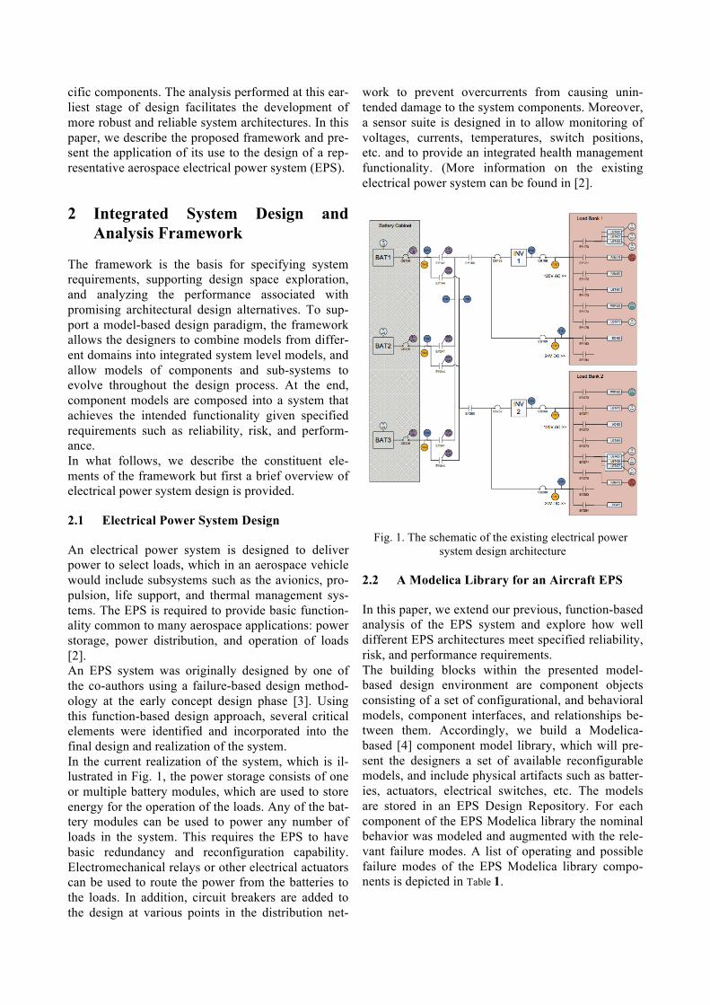
An electrical power system is designed to deliver power to select loads, which in an aerospace vehicle would include subsystems such as the avionics, pro-pulsion, life support, and thermal management sys-tems. The EPS is required to provide basic function-ality common to many aerospace applications: power storage, power distribution, and operation of loads [2]. An EPS system was originally designed by one of the co-authors using a failure-based design method-ology at the early concept design phase [3]. Using this function-based design approach, several critical elements were identified and incorporated into the final design and realization of the system. In the current realization of the system, which is il-lustrated in Fig. 1, the power storage consists of one or multiple battery modules, which are used to store energy for the operation of the loads. Any of the bat-tery modules can be used to power any number of loads in the system. This requires the EPS to have basic redundancy and reconfiguration capability. Electromechanical relays or other electrical actuators can be used to route the power from the batteries to the loads. In addition, circuit breakers are added to the design at various points in the distribution net-
work to prevent overcurrents from causing unin-tended damage to the system components. Moreover, a sensor suite is designed in to allow monitoring of voltages, currents, temperatures, switch positions, etc. and to provide an integrated health management functionality. (More information on the existing electrical power system can be found in [2].
Fig. 1. The schematic of the existing electrical power system design architecture
2.2 A Modelica Library for an Aircraft EPS
In this paper, we extend our previous, function-based analysis of the EPS system and explore how well different EPS architectures meet specified reliability, risk, and performance requirements. The building blocks within the presented model-based design environment are component objects consisting of a set of configurational, and behavioral models, component interfaces, and relationships be-tween them. Accordingly, we build a Modelica-based [4] component model library, which will pre-sent the designers a set of available reconfigurable models, and include physical artifacts such as batter-ies, actuators, electrical switches, etc. The models are stored in an EPS Design Repository. For each component of the EPS Modelica library the nominal behavior was modeled and augmented with the rele-vant failure modes. A list of operating and possible failure modes of the EPS Modelica library compo-nents is depicted in Table 1.

Table 1. A list of components of the EPS Modelica libraries and the associated nominal operating and failure modes.
Model Element Element Type
Operating and fault modes
Battery Source Nominal, AbruptParasiti-cLoad
CircuitBreaker Electrical Circuit Breaker
Nominal, Tripped, FailedOpen, Stuck-Closed
Relay Electome-chanical Re-lay
NominalClosed, NominalOpen, StuckOpen
Inverter Electrical Inverter
NominalOn, Nomi-nalOff, FailedOff
Temperature-Sensor
Temperature Sensor
Nominal, Drift, Offset, Intermitten-tOffset, Stuck
DCCurrent-Tranmitter
DC Current Transmitter (50A Max)
Nominal, Drift, Offset, Intermitten-tOffset, Stuck
DCVoltageSen-sor
DC Voltage Sensor 10HZ
Nominal, Drift, Offset, Intermitten-tOffset, Stuck
PositionSensor Actuator Posi-tion Sensor 10HZ
Nominal, Stuck
ACResistor DCResistor
AC and DC Resistors
Nominal, FailedOff, IntermittentResis-tanceOffset, Resis-tanceDrift, Resis-tanceOffset
LargeFan LargeFan Nominal, Over-Speed, UnderSpeed, FailedOff
LightBulb 25W Light Bulb
Nominal, FailedOff
WaterPump Water Pump Nominal, FlowRestricted, FailedOff
For several components, models with different levels of detail have been created. For example, the Inverter component created Modelica models are ranging from very simple models that describe only the AC/DC power balance equation to models con-taining complicated electrical schematics including semiconductor components from the Electrical Stan-dard Modelica Library. The reason for creating mod-els of the same component with different levels of details was to compare how our proposed architec-ture analysis methods performs in very early stages of the conceptual analysis, when not so much details are be available, to later stages when more details are added to the component models.
The nominal and the fault modes behavior of the Modelica EPS Library components have been vali-dated by comparing the simulation behavior of two test models with measurements and sensor data from the Advanced Diagnostics and Prognostics testbed called ADAPT located at the NASA Ames Research Center [5,6]. (The ADAPT system consists of a con-trolled and monitored environment where faults can be injected into the system in a controlled manner and the performance of the test article is carefully monitored.) The first test Modelica model, called the ADAPT Tier 1 (ADAPT Lite) model, depicted in Fig 2, con-tains a battery connected through a series of circuit breakers and relays to an inverter, and several loads consisting of a large fan, a DC resistor and AC resis-tor. The rotation speed of the fan is measured by a speed transmitter component. A series of four AC or DC voltage sensors and three current transmitters measure the voltage and current in different probing points of the circuit. The circuit breakers can be commanded externally to be closed or open and their position is monitored with the help of a position sen-sor connected to them. The second EPS model (ADAPT Tier2) that has been tested and built in Modelica is depicted in Fig 3 and it is equivalent to the schematic represented in Fig 1. In this model the ADAPT Tier 2 EPS supplies power to five critical load functions and four non-critical loads distributed in two load banks. The bat-tery cabinet unit contains three battery packs and several relays that control the connections between the load bank and the batteries. Similarly to the ADAPT Lite model, the testbed is controlled by a number of relays and monitored by a large set of sensors. The ADAPT Tier 1 model has been validated against 39 experiments while the ADAPT Tie2 model has been validated against 33 experiments simulating nominal and faulty behavior of the EPS. Since each component contains a description of the failure behavior besides the description of the nomi-nal behavior, by systematically selecting a certain state of the system and inducing faults in the compo-nents, we were able to observe the effects of those faults on the system and automatically build a Fail-ure Model and Effect Analysis (FMEA) table from the model.

Fig. 2. The Modelica model of simple EPS system (ADAPT Tier 1).
Fig. 3. The schematic of the existing electrical power system design architecture.
2.3 Design Space Exploration
This section examines the means of exploring the design space defined by combinations of generic EPS components. Feasible EPS candidate architec-tures are generated by a generative grammar based design space exploration technique. This generative
technique takes user specified EPS loads as input and satisfies system-level configuration requirements to generate feasible EPS candidate architectures. The component model library serves as the backbone of the proposed design space exploration approach. Us-ing the models in the model library as building blocks, this generative graph grammar based tech-nique configures “correct by construction” EPS ar-

chitectures that can be further studied by means of a simulation-based analysis. Graph grammar based configuration approach uses graph as representation scheme. These approaches capture the transitions or the production rules for creating a solution, as opposed to storing the solu-tions themselves. Accordingly, a configuration’s de-velopment from its inception to its final configura-tion is considered as a series of graph modifications. The initial specification can be represented as a sim-ple graph in which the desired inputs and outputs are cast as arcs and nodes of the to-be-designed artifact. From this initial specification, the design process can be viewed as a progression of graph transformations that lead to the final configuration [7]. Recently, en-gineering design researchers have discovered that graph grammars provide a flexible yet ideally struc-tured approach to the creation of complex engineer-ing systems [8-10]. This interpretation of the design process makes graph grammars very suitable for computationally modeling the open-ended nature of conceptual design, where designers explore various ideas, decisions, and modifications to previous de-signs to arrive at feasible solutions. Generating feasible EPS architecture using graph grammar based configuration approach is a two-step process: In the first step, we have developed an EPS system design grammar to encode design rules for constructing electrical power system architectures. For EPS, we have developed a 14-rule graph gram-mar that defines ways to generate feasible EPS archi-tectures from multiple EPS requirement documents [11-15]. The rules are established prior to the design process and capture architectural design considera-tions that are inherent to the EPS design problem. One such EPS design requirement is shown in Figure
4. Similar design rules govern the mapping of func-tional requirements to components, or the physical compatibility between EPS components. Moreover, the graph grammar rules can be formulated in such a way that the final solution meets the constraints of the problem. The knowledge captured in the rules offer the option of exploring the design alternatives as well as automating the design generation process. Specifically, the developed design grammar encodes how specific system requirements can be embodied by selecting components from a full spectrum of electromechanical components represented in the component library. In the second step, the graph transformation systems, or graph grammars, is invoked algebraically. Alge-braic graph transformation methods rigorously de-fine mathematical operations such as addition and intersection of graphs. A typical graph grammar rule is compromised of a left-hand side (LHS) and a right-hand side (RHS) (Figure 5). The LHS contains the conditions, upon which the applicability of a rule is determined. Accordingly, the LHS describes the state of the graph for a particular rule to be applica-ble. The RHS, on the other hand, contains the result-ing graph transformation. It describes the new state of the graph after the application of the rule. By sim-ply executing different combinations of grammar rules, a variety of feasible EPS architectures can eas-ily be generated including the architecture of the ADAPT test bed shown in Figure 1. A partial sequence of application of different EPS grammar rules to create a feasible EPS architecture is shown in Figure 6. In order to generate a feasible EPS architecture the approach starts with a seed graph. The seed graph for EPS design space explora-tion is graph based representation of three main
Fig. 4. An architectural design requirement that is used in derivation of a design grammar
Figure 5. A graph grammar rule for EPS architecture generation
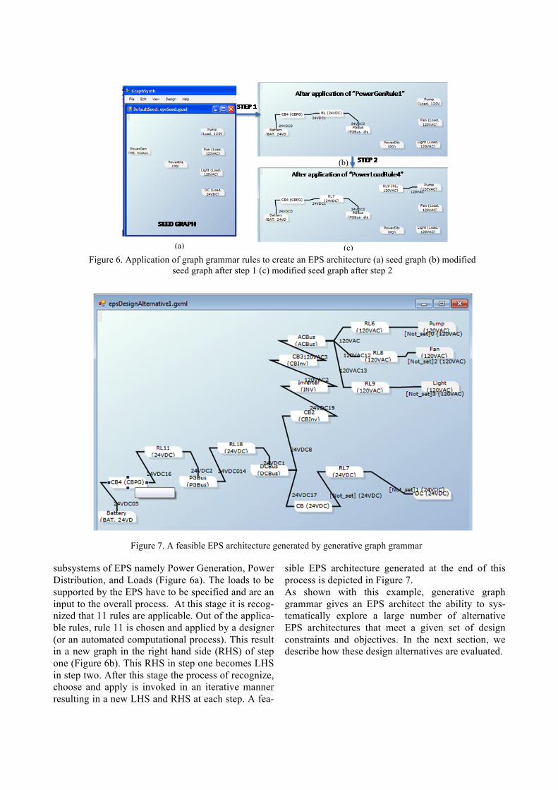
subsystems of EPS namely Power Generation, Power Distribution, and Loads (Figure 6a). The loads to be supported by the EPS have to be specified and are an input to the overall process. At this stage it is recog-nized that 11 rules are applicable. Out of the applica-ble rules, rule 11 is chosen and applied by a designer (or an automated computational process). This result in a new graph in the right hand side (RHS) of step one (Figure 6b). This RHS in step one becomes LHS in step two. After this stage the process of recognize, choose and apply is invoked in an iterative manner resulting in a new LHS and RHS at each step. A fea-
sible EPS architecture generated at the end of this process is depicted in Figure 7. As shown with this example, generative graph grammar gives an EPS architect the ability to sys-tematically explore a large number of alternative EPS architectures that meet a given set of design constraints and objectives. In the next section, we describe how these design alternatives are evaluated.
(c)
(b)
(a)
Figure 6. Application of graph grammar rules to create an EPS architecture (a) seed graph (b) modified seed graph after step 1 (c) modified seed graph after step 2
Figure 7. A feasible EPS architecture generated by generative graph grammar

2.4 Simulation-Based Performance Analysis
Let us consider the following set of safety, functional and performance requirements imposed on the EPS system. Safety Requirements imposed in the architecture: • “AFGS-87219A: A battery relay shall be in-
stalled in each battery circuit to enable the flight crew to isolate the battery from the rest of the electric subsystem.”
• “MIL-STD 7080: A switch or relay shall be con-nected in series with the circuit breaker when a switching capability is required for a circuit pro-tected by a circuit breaker.”
Functional Requirements: • “MIL-STD 704F: “Loads should not introduce
excessive current distortion such that other EPS functionality is effected.”
Performance Requirements: • “MIL-STD-1275D: The [28 VDC electrical
power system] circuit steady-state voltage shall be between 25 VDC and 30 VDC.”
• “MIL-STD-1275D: The rotational speed of cool-ing fan system should be between 765 and 900 rpm.
As it was described in Section 2.3 feasible EPS can-didate architectures are generated by a generative grammar based design space exploration technique. The graph grammar configuration approach is able to impose the safety requirements detailed above by encoding the safety requirements in graph grammar rules that are applied by the transformation system resulting in an architecture that is correct by defini-tion. The Modelica model of a simple EPS system, (ADAPT Tier2) depicted in Fig 2 satisfy both safety requirements: the relay EY244 will isolate the bat-tery from the rest of the electrical circuit (the first safety requirement AFGS-87219A) while the circuit breaker-relay pairs (CB236-EY244, CB266-E272, CB266-EY275, CB280-EY284) will satisfy the sec-ond requirement from MIL-STD 7080. The functional and performance requirements, on the other hand, are verified by simulation. Simulation-based design methods require the capability of speci-fying detailed input design parameters and using them to obtain a model response. Accordingly, we use a simulation process which allows system de-signers use to account for the effects of variability in the input and design parameters on the model re-sponse, thereby incorporating uncertainty into the design process. In this research, we use a sampling
based technique to perform a simulation-based analysis of system performance. This analysis pro-vides a means to estimate the probability of system response and assess how well a candidate system design meets its requirements. For example, in the ADAPT Tier 1 EPS the designer has the choice of using a Xantrex Prosine 1000 In-vertor or a Xantrex Freedom HW 1000 Invertor. Both variants will satisfy the safety requirements imposed on the architecture. The Xatrex Prosine 1000 Watt Inverter has a peak efficiency of 90% while the output voltage (over full load and battery voltage range) is around 120 Vac - 10 %/+4 %. The range of the output voltage for this type of invertor can be defined as a triangular probability distribution function. The output voltage histogram for 200 sam-ples is depicted in Figure 8.
Figure 8. The Xantrex Prosine 1000 Invertor output volt-
age histogram. We perform a simulation based performance analysis and we compute the rotational speed of the cooling fan for different output voltages of the inverter. The histogram of the rotational speed of the cooling fan shows that using a Xantrex Prosine 1000 Invertor is a valid architecture, which satisfies the performance requirement that the speed of the cooling fan should be between 765 and 900 rpm.
Figure 9. The histogram of the rotational speed of the cooling fan when a Xantrex Prosine 1000 invertor is used.

The Xantrex Freedom HW 1000 Invertor has slightly different characteristics: a peak efficiency of 83% and an output voltage (over full load and battery voltage range) around 115 Vac +/-10 Vac that can be also approximated as a triangular distribution func-tion. The histogram of the output voltage is shown in Figure 10.
Figure 10. The Xantrex Freedom HW 1000 Invertor
output voltage histogram.
A performance based simulation shows that the rota-tional speed of the cooling fan can sometimes drop below 765 rpm for certain AC output voltages of the Xantrex Freedom HW 1000 Invertor (see Figure 11).
Figure 11. The histogram of the rotational speed of the cooling fan when a Xantrex Freedom HW 1000 invertor is
used. Since the performance requirements of an EPS archi-tecture using a Xantrex Freedom 100 Invertor are not met, this architecture can be discarded from the list of alternative EPS designs.
3 Conclusions
We have outlined a framework for simulation-based design that integrates architectural synthesis and analysis of complex systems during the conceptual design phase. The incorporation of automated design space exploration methods with Modelica broadens the scope of the capabilities of the language, and en-ables it to support architectural trade studies before
costly design decisions are made. In this paper, we presented preliminary results of our study. In the fu-ture, we plan to fully integrate and automate the ar-chitectural synthesis and analysis approaches de-scribed in this paper.
References
[1] Defense Advanced Research Projects Agency (DARPA), Tactical Technology Of-fice (TTO) META-II, BAA-10-59, 2010.
[2] S. Poll, A. Patterson-Hine, J. Camisa, D. Garcia, and D. Hall, "Advanced Diagnostics and Prognostics Testbed," in 18th International Workshop on Principles of Diagnosis (DX-07) Nashville, TN, 2007.
[3] T. Kurtoglu, Jensen, D., Tumer I.Y., “A Functional Failure Reasoning Methodology for Evaluation of Conceptual System Archi-tectures”, Journal of Research in Engineering Design, published online, January 31, 2010.
[4] Modelica Language, www.modelica.org [5] Poll Scott, Ann Patterson-Hine, Joe Camisa,
David Garcia, David Hall, Charles Lee, Ole J. Mengshoel, Christian Neukom, David Nishikawa, John Ossenfort, Adam Sweet, Serge Yentus, Indranil Roychoudhury, Mat-thew Daigle, Gautam Biswas, and Xenofon Koutsoukos. (2007). "Advanced Diagnostics and Prognostics Testbed." In Proceedings of the International Workshop on Principles of Diagnosis (DX-07). (Nashville, TN, May 2007, 2007).
[6] NASA Ames Research Center (2006) "Ad-vanced Diagnostics and Prognostics Testbed (ADAPT) System Description, Operations, and Safety Manual," February, 2006.
[7] Cagan, J., 2001, “Engineering Shape Grammars,” Formal Engineering Design Synthesis, Antonsson, E. K., and J. Cagan, eds., Cambridge University Press.
[8] Rai, R., Kurtoglu, T., and Campbell, M., 2009,"Stochastic interactive graph grammar search for conceptual design" ASME Journal of Computing and Information Sciences in Engineering (Accepted for Publication with review).
[9] Kurtoglu, T., Campbell, M., “Automated Synthesis of Electromechanical Design Configurations from Empirical Analysis of Function to Form Mapping”. Journal of Engineering Design, Vol. 20 (1), Feb 2009.

[10] Shea, K., J. Cagan, and S.J. Fenves, 1997, “A Shape Annealing Approach to Optimal Truss Design with Dynamic Grouping of Members", ASME Journal of Mechanical Design, Vol 119, No. 3, pp. 388-394.
[11] DEPARTMENT OF DEFENSE, “Aircraft electric power characteristics”, MIL-STD-704F, 12 March 2004.
[12] DEPARTMENT OF DEFENSE, “Air Force Specification Guide: Electrical Power Systems”, Aerospace Vehicles, AFGS-87219A, 30 March 1993.
[13] DEPARTMENT OF DEFENSE, “Characteristics of 28 Volt DC Electrical Systems in Military Vehicles”, MIL-STD-1275D, 29 August 2006.
[14] DEPARTMENT OF DEFENSE, “Selection and Instillation of Aircraft Electronic Equipment”, MIL-STD-7080, 31 May 1994
[15] DEPARTMENT OF DEFENSE, “Joint services specification guide (JSSG-2009) air vehicle subsystems”, Appendix H, 30 October 1998.