Embed Size (px)
Citation preview
Nonlinear Dynamics (2006)DOI: 10.1007/s11071-005-9012-x c© Springer 2006
Simulating Multibody Dynamics With Rough Contact Surfaces
and Run-in Wear
JANKO SLAVIC∗ and MIHA BOLTEZARFaculty of Mechanical Engineering, Laboratory for Dynamics of Machines and Structures, University of Ljubljana, Askerceva6, 1000 Ljubljana, Slovenia; ∗Author for correspondence (e-mail: [email protected]; fax: 386 125.18567)
(Received: 1 August 2005; accepted: 31 October 2005)
Abstract. The overall dynamics of a multibody system is actually a multi-scale problem because it depends a great deal onthe local contact properties (coefficient of restitution, friction, roughness, etc). In this paper we found that the briefly presentedforce-based theory of plane dynamics for a multibody system with unilateral contacts was appropriate for simulating detailedmulti-contact situations of rough contacting surfaces.
The focus of the paper is on a geometrically detailed description of rough surfaces. To achieve the run-in effect of the contactingsurfaces under dynamical loads the contacting surfaces need to be re-shaped. For the re-shaping a wear model based on the localloss of mechanical energy under dynamical loads is presented.
The new ideas are presented for a numerical analysis of measuring the coefficient of friction at the rim of a wheel (rotatingbody). With the help of the analysis the experimentally observed change in the measured coefficient of friction of up to 30% foronly slightly altered experimental conditions is explained.
Key words: brake dynamics, loss of mechanical energy at contacts, multibody dynamics, re-shaping, rough, unilateral contacts,wear model
1. Introduction
The mathematical formulation of multibody dynamics with unilateral contacts has received much interestin recent decades; however, it was only in the past decade that the formulation was developed to thenecessary mathematical and physical consistency. Some of the first studies on multibody dynamics withbilateral contacts were done by Vereshchagin [29], Armstrong and Green [2] and Featherston [3] in the1970s and 1980s.
The first studies of unilateral contacts in the form of a linear complementarity problem were publishedby Lotstedt [16, 17].
In recent years, the time-stepping methods which are due to Moreau [19] are being developed partic-ularly rapidly. These methods operate in the impulse-velocity domain; therefore, at impact there is noneed to switch from the force-acceleration domain to the impulse-velocity domain. Furthermore, thesemethods do not need to find the impact time, but usually use very small fixed time-step which definesthe precision of the simulation. These methods are robust, easily to implement and can be used for dy-namical systems with large number of contacts. An important contribution to the time-stepping methodswas made by Monteiro-Marques [18], Paoli and Schatzman [21, 22], who studied the convergence ofthe solution, and also by Stewart and Trinkle [26, 27], Anitesca and Potra [1] and others.
In comparison to the time-stepping methods the event-driven methods use normal ODE integrationmethods at smooth contact-free phases and switch to contacts-solving at contact events. The accuracyof event-driven methods can be higher then the accuracy of time-stepping methods, but the event-drivenmethods are not appropriate for large number of contacts. Furthermore, the time-stepping as a numerical
J. Slavic and M. Boltezar
method may overcome some difficulties (such as accumulation points) that can not be handled in aconvincing way by e.g, the event-driven methods. A comparison of both methods is given in the workof Leine and Nijmeijer [14].
In this research Pfeiffer and Glocker [4, 23] event-driven formulation is used; their work presents amathematically clear and physically consistent basis for plane contact dynamics and is superior to theclassical approach in its uniform way of solving the stick-slip, detachment and impact events. There isalso no need to adapt the number of generalized coordinates at any time. The strength of the formulationis in its simplicity and generality of use. Pfeiffer and Glocker introduced a new friction decompositionthat avoids singularities in the presence of dependent coordinates and can also handle over-constrainedsystems. They also introduced, for the first time, the impact law with friction as a linear complementaryproblem [23].
The friction decomposition presented in [4, 23] is quite cumbersome because it uses four unilateralprimitives for one friction curve; however, a more advance decomposition which uses only two unilat-eral primitives was presented by Rossmann et al. [24] and extended to spatial friction as a nonlinearcomplementarity problem [5, 7]. Further extensions towards spatial systems can be found in [6, 10, 12].
The contact dynamics research is often focused towards simplified contacting surfaces of one contact-ing point only (e.g., the pad of a brake is reduced to a point mass [9]). However, the geometrically quitesimple contacting surfaces are usually enhanced with advanced contact laws [8, 15, 31]. To researchthe importance of the geometrically detailed contacting surfaces in this research the force-based theoryis used with basic contact laws but with geometrically complex contacting surfaces.
This work is organized as follows: in the second section of this research the formulation [4, 23] ofmultibody plane dynamics with unilateral contacts is adapted to bodies with arbitrary body shapes. Thethird section presents the local loss of mechanical energy and its role in defining the wear of contactingrough surfaces under dynamic loads. The fourth section presents a numerical example with run-in wear.In addition, an explanation for the apparent change of the coefficient of friction for disk-shaped bodiesis given. The last section presents the conclusions.
2. Multibody Dynamics with Unilateral Contacts as a Linear Complementarity Problem
For the sake of completeness this section gives a brief review of the mathematical modeling of multibodydynamics with unilateral contacts as presented by Glocker and Pfeiffer [4, 23]. The methods are presentedfor linear contacts (plain dynamics), but with some modifications they can also be used for plane contacts(3D spatial dynamics) [5–7, 10, 12, 30].
The equations of motion for a multibody system with f degrees of freedom (including only bilateralcontacts) can be written as:
M(q, t) q − h(q, q, t) = 0 ∈ R f , (1)
where M is the mass matrix, q is the vector of generalized coordinates and h is the vector of generalizedactive forces. If there is a set of i ∈ IN contact forces then the equations of motion will be:
M q − h =∑i∈IN
QCi ∈ R f , (2)
where QCi are the generalized, non-conservative active forces.
Simulating Multibody Dynamics with Rough Contact Surfaces and Run-in Wear
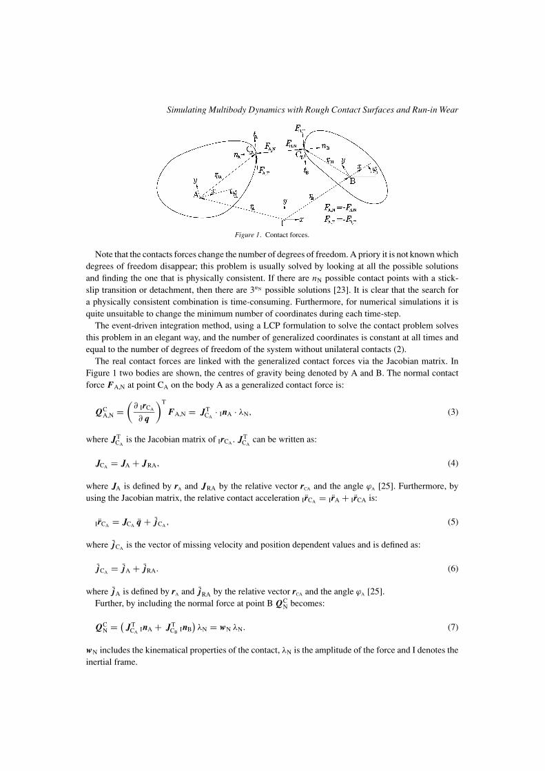
Figure 1. Contact forces.
Note that the contacts forces change the number of degrees of freedom. A priory it is not known whichdegrees of freedom disappear; this problem is usually solved by looking at all the possible solutionsand finding the one that is physically consistent. If there are nN possible contact points with a stick-slip transition or detachment, then there are 3nN possible solutions [23]. It is clear that the search fora physically consistent combination is time-consuming. Furthermore, for numerical simulations it isquite unsuitable to change the minimum number of coordinates during each time-step.
The event-driven integration method, using a LCP formulation to solve the contact problem solvesthis problem in an elegant way, and the number of generalized coordinates is constant at all times andequal to the number of degrees of freedom of the system without unilateral contacts (2).
The real contact forces are linked with the generalized contact forces via the Jacobian matrix. InFigure 1 two bodies are shown, the centres of gravity being denoted by A and B. The normal contactforce FA,N at point CA on the body A as a generalized contact force is:
QCA,N =
(∂ IrCA
∂ q
)T
FA,N = JTCA
· InA · λN, (3)
where JTCA
is the Jacobian matrix of IrCA . JTCA
can be written as:
JCA = JA + JRA, (4)
where JA is defined by rA and JRA by the relative vector rCA and the angle ϕA [25]. Furthermore, byusing the Jacobian matrix, the relative contact acceleration IrCA = IrA + IrCA is:
IrCA = JCA q + jCA , (5)
where jCA is the vector of missing velocity and position dependent values and is defined as:
jCA = jA + jRA. (6)
where jA is defined by rA and jRA by the relative vector rCA and the angle ϕA [25].Further, by including the normal force at point B QC
N becomes:
QCN = (
JTCA InA + JT
CB InB)λN = wN λN. (7)
wN includes the kinematical properties of the contact, λN is the amplitude of the force and I denotes theinertial frame.
J. Slavic and M. Boltezar
By using a similar notation for the tangential force (index T), Equation (2) is rewritten as:
M q − h −∑i∈IN
(wN λN + wT λT)i = 0 ∈ R f . (8)
Or by using matrix notation:
WN = {wNi }, WT = {wTi }, i ∈ IN, (9)
the equations of motion are:
M q − h − ( WN WT )
(λN
λT
)= 0 ∈ R f . (10)
The contact situations are solved in two steps: in the first, the non-smooth impact with friction is solved(see Section 2.2); in the second the stick-slip or detachment situation is solved (see Section 2.1). Whilethe impact is solved in the impulse-domain, the stick-slip or detachment is solved in the force-domain.
All the possible contact points IG are organized in four sets during each time-step :
IG = {1, 2, . . . , nG}IS = {i ∈ IG ; gN = 0} nS elements,IN = {i ∈ IS ; gN = 0} nN elements,IH = {i ∈ IN ; gT = 0} nH elements.
(11)
The set IS contains all the closed contacts, the set IN contains only the contacts with vanishing relativenormal velocities (stick-slip or detachment), and the set IH contains the possibly sticking contacts. Thenumber of elements in the sets can change during each time-step.
2.1. STICK-SLIP TRANSITION OR DETACHMENT
First, the stick-slip transition or detachment problem is solved on an impact-free set IN. The equationsof motion (10) and the relative contact accelerations g are [4, 23, 13]:
M q − h − ( WN + WG μG WH )
(λN
λH
)= 0 ∈ R f , (12)(
gN
gH
)=
(WT
N
WTH
)q +
(wN
wH
)∈ RnN+nH . (13)
The index N denotes the normal direction, and the index H denotes the tangential direction of thepossibly sticking set IH. The new index G denotes the sliding contacts (the tangential force is known)of the set IN \ IH and the μG diagonal matrix of friction coefficients. The additional nN + nH equationsthat are needed to solve the Equations (12) and (13) are represented by the complementarity conditionsin the normal and tangential directions, details are given in [23].
Simulating Multibody Dynamics with Rough Contact Surfaces and Run-in Wear
2.2. IMPACT WITH FRICTION
While the stick-slip or detachment transition is solved in the force-acceleration domain, the impact issolved in the impulse-velocity domain. Some common assumptions for rigid-body impacts are made:the duration of the impact is infinitely short, the wave effects are not taken into account, during theimpact all positions and orientations, and all the non-impulsive forces and torques remain constant. Theimpact is divided into two phases: the compression phase (time interval: tA − tC) and the expansionphase (time interval: tC − tE). In this work Poisson’s impact law is used.
For impacts the contacts of the set IS are taken into account.
2.2.1. Compression PhaseThe index C is used for the compression phase. By integrating the equation of motion (10) an impulse-domain equation is built [23]:
M (qC − qA) − ( WN WT )
(ΛNC
ΛTC
)= 0 ∈ R f . (14)
The relative contact velocities are:
(gNC
gTC
)=
(WT
N
WTT
)(qC − qA) +
(gNA
gTA
)∈ R2 nS . (15)
ΛNC and ΛTC are the contact impulses during the compression phase, and A and C represent the begin-ning and the end of the compression. Similarly, as before, for the missing 2 nS equations complementarityconditions in the normal and tangential directions can be found, details are given in [23].
2.2.2. Expansion PhaseThe expansion phase starts from the end of the compression phase and is resolved in a similar wayto the compression, except that some attention needs to be paid to the impenetrability conditions and,optionally, to the reversibility of the tangential contact [23].
3. Wear Model Under Dynamic Loads
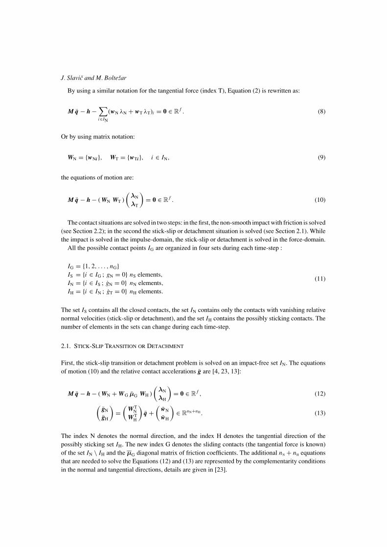
When two (or more) bodies are in unilateral contact (sticking, slipping, impacting) then the con-tacting surfaces are exposed to mechanical wear. In order to identify the rate of mechanical wearin this research we used the loss of mechanical energy W (s) at the contacting surfaces, seeFigure 2.
Figure 2. Two bodies in dynamical contact and the loss of mechanical energy (shaded).
J. Slavic and M. Boltezar
The wear rate rW is defined in terms of the maximum loss of mechanical energy of each body:
rW (s) = W (s)
Max(W ). (16)
The actual wear (reshaping) amplitude u(s) of the contacting surfaces is:
u(s) = uMax rW (s), (17)
where uMax is the maximum change of shape (a measure of the size of the wear particle) between twosimulations. The direction of reshaping is to the inside of the body, according to the normal contactvector, see Figure 1.
To achieve the steady-state contact-surface-shape usually several re-shapings need to be done. Aftereach re-shaping the simulation needs to be run again to determine the loss of mechanical energy W (s)at the current contact shapes.
3.1. LOSS OF MECHANICAL ENERGY IN THE CONTACT SITUATION
The loss of mechanical energy during impact situations (for stick-slip the procedures are very similar)is defined by the loss during the compression phase summed with the loss during the expansion phase.
During the compression phase the local loss of mechanical energy is defined as (A denotes the startof compression and C the end of compression):
WC = gAC IC, (18)
where:
IC = In �NC + It �TC (19)
is the impulse during the compression phase (in the local contact coordinate system) and:
gAC = gA + gC
2. (20)
is the average relative contact velocity.The loss of mechanical energy during the expansion phase is similar, except that the indexes are as
follows: C is replaced with E, to denote the end of compression; and A is replaced with C, to denotethe start of expansion.
4. Numerical Examples
4.1. MATHEMATICAL MODEL
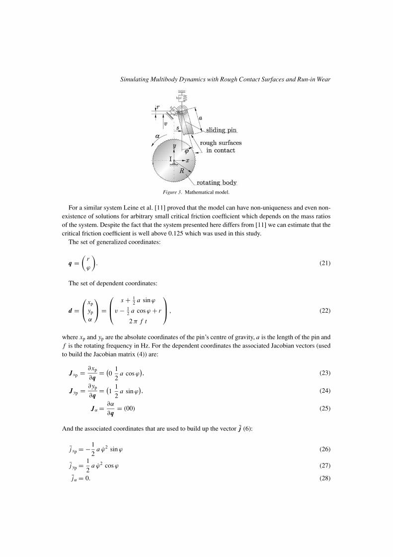
In this section the presented methods will be shown on a numerical example of a sliding pin in contactwith a round (rotating) surface, see Figure 3. The system has 2 degrees of freedom: the translationaldegree of freedom r and the rotational degree of freedom ϕ. As shown in Figure 3 in each of thesedirections a spring-damper element is present. The symbols s andv define the starting positions of the pin.
Simulating Multibody Dynamics with Rough Contact Surfaces and Run-in Wear
Figure 3. Mathematical model.
For a similar system Leine et al. [11] proved that the model can have non-uniqueness and even non-existence of solutions for arbitrary small critical friction coefficient which depends on the mass ratiosof the system. Despite the fact that the system presented here differs from [11] we can estimate that thecritical friction coefficient is well above 0.125 which was used in this study.
The set of generalized coordinates:
q =(
rϕ
). (21)
The set of dependent coordinates:
d =⎛⎝ xp
yp
α
⎞⎠ =
⎛⎜⎝ s + 12 a sin ϕ
v − 12 a cos ϕ + r
2 π f t
⎞⎟⎠ , (22)
where xp and yp are the absolute coordinates of the pin’s centre of gravity, a is the length of the pin andf is the rotating frequency in Hz. For the dependent coordinates the associated Jacobian vectors (usedto build the Jacobian matrix (4)) are:
Jxp = ∂xp
∂q= (
01
2a cos ϕ
), (23)
J yp = ∂yp
∂q= (
11
2a sin ϕ
), (24)
Jα = ∂α
∂q= (00) (25)
And the associated coordinates that are used to build up the vector j (6):
j xp = −1
2a ϕ2 sin ϕ (26)
j yp = 1
2a ϕ2 cos ϕ (27)
jα = 0. (28)
J. Slavic and M. Boltezar
The mass matrix M and the vector of active forces h:
M =(
m 12 a m sin ϕ
12 a m sin ϕ 1
4 a2 m cos2 ϕ + 14 a2 m sin2 ϕ + Jzz
), (29)
h =(− 1
2 a m cos ϕ ϕ2 − p kϕ − kr r − cr r−kϕ ϕ − cϕ ϕ
). (30)
Where a, m and Jzz are the length, mass and the mass moment of inertia (about the centre of gravity)of the pin, respectively. Furthermore, kr , dr and kϕ, dϕ are the stiffness and the damping parameters forthe r and ϕ directions, respectively.
Finally, p is the parameter that defines the pre-stress in the spring in the r direction at r = 0.In thepresented example the following parameters were used:
a = 0.001 m, s = 0 m, v = 0.01200116 m, cϕ = 2.12 10−5 Nms/rad, cr = 4.32 10−2 Ns/m, p =9.40 10−6 m, f = 4 Hz, kϕ = 0.0791 Nm/rad, kr = 329.9 kN/m.
Additionally, the width and the depth of the pin are equal to a, and the radius of the rotating bodyis R = 0.011 m, see Figure 3. The density of the pin is ρ = 1650 kg/m3. The mass parameters arecalculated according to the current shapes, which are about to change.
The used contact parameters are as follows μ = 0.125, εN = 0.5, εT = 0.5, ν = 0, where μ isthe coefficient of friction and εN and εT are the coefficients of restitution in the normal and tangentialdirections. ν is used for the reversibility in the tangential direction [23].
Simulation parameters. Usually, the largest natural frequency defines ( fr,0 = 210 kHz and fϕ,0 =103 kHz) the time-step of the simulation; however, it was observed that the non-smooth impact situationsare more critical and the longest time-step used in this simulation is therefore T = 10−9 s.
The total time of the simulation, 10−3 s, corresponds to a relative displacement between the pin and therotating body of 0.27 mm. The maximum allowed penetration depth between the bodies is 2.5 · 10−8 m.
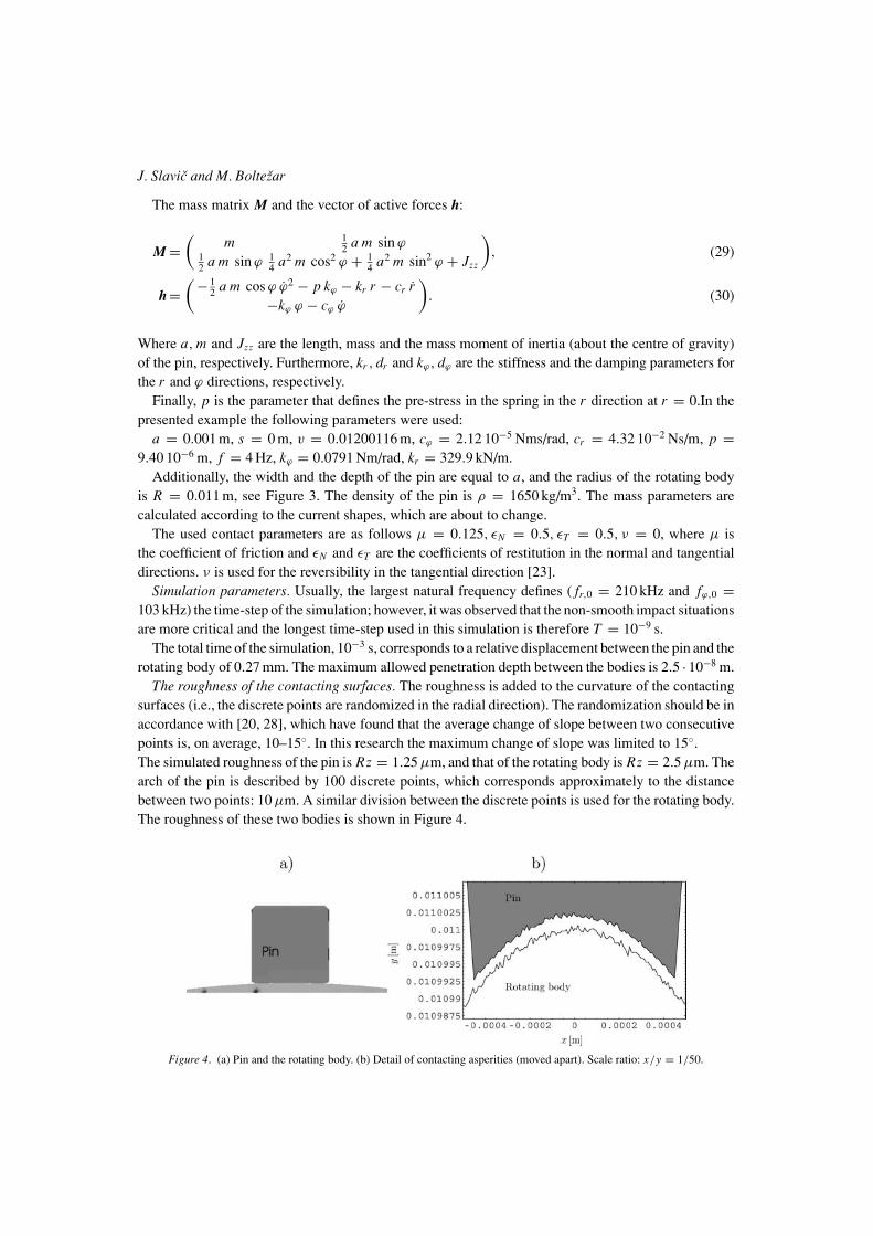
The roughness of the contacting surfaces. The roughness is added to the curvature of the contactingsurfaces (i.e., the discrete points are randomized in the radial direction). The randomization should be inaccordance with [20, 28], which have found that the average change of slope between two consecutivepoints is, on average, 10–15◦. In this research the maximum change of slope was limited to 15◦.The simulated roughness of the pin is Rz = 1.25 μm, and that of the rotating body is Rz = 2.5 μm. Thearch of the pin is described by 100 discrete points, which corresponds approximately to the distancebetween two points: 10 μm. A similar division between the discrete points is used for the rotating body.The roughness of these two bodies is shown in Figure 4.
Figure 4. (a) Pin and the rotating body. (b) Detail of contacting asperities (moved apart). Scale ratio: x/y = 1/50.
Simulating Multibody Dynamics with Rough Contact Surfaces and Run-in Wear
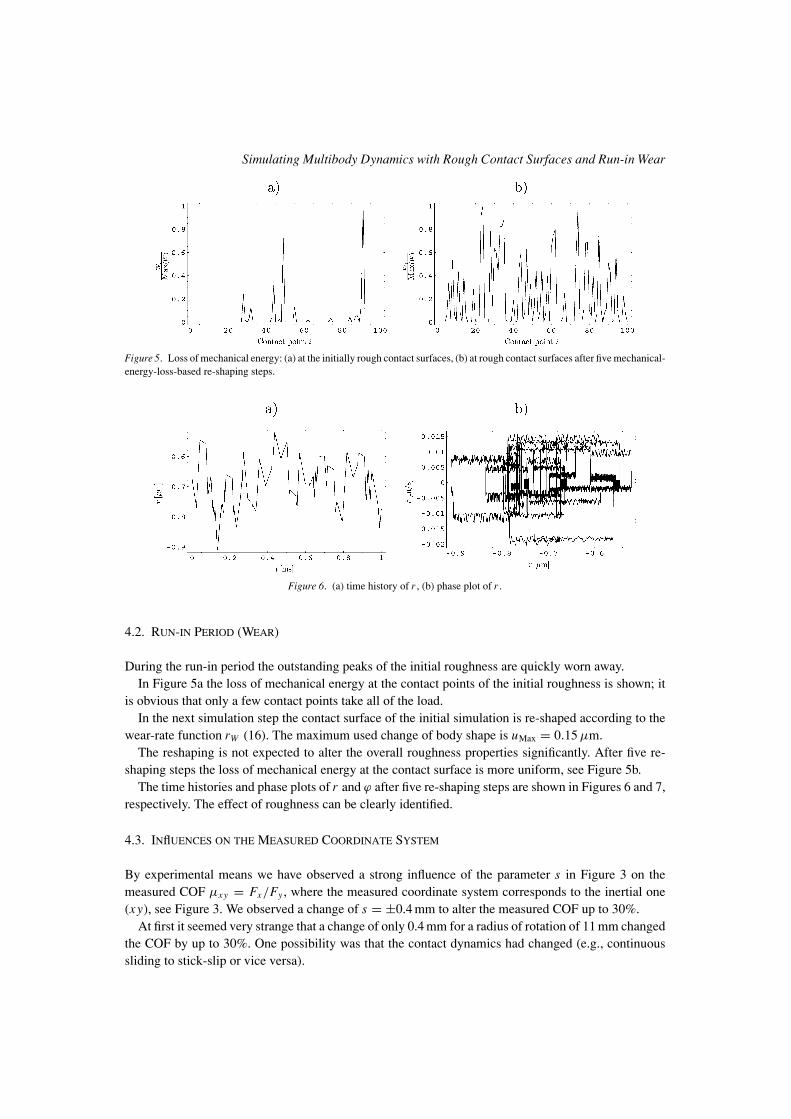
Figure 5. Loss of mechanical energy: (a) at the initially rough contact surfaces, (b) at rough contact surfaces after five mechanical-energy-loss-based re-shaping steps.
Figure 6. (a) time history of r , (b) phase plot of r .
4.2. RUN-IN PERIOD (WEAR)
During the run-in period the outstanding peaks of the initial roughness are quickly worn away.In Figure 5a the loss of mechanical energy at the contact points of the initial roughness is shown; it
is obvious that only a few contact points take all of the load.In the next simulation step the contact surface of the initial simulation is re-shaped according to the
wear-rate function rW (16). The maximum used change of body shape is uMax = 0.15 μm.The reshaping is not expected to alter the overall roughness properties significantly. After five re-
shaping steps the loss of mechanical energy at the contact surface is more uniform, see Figure 5b.The time histories and phase plots of r and ϕ after five re-shaping steps are shown in Figures 6 and 7,
respectively. The effect of roughness can be clearly identified.
4.3. INflUENCES ON THE MEASURED COORDINATE SYSTEM
By experimental means we have observed a strong influence of the parameter s in Figure 3 on themeasured COF μxy = Fx/Fy , where the measured coordinate system corresponds to the inertial one(xy), see Figure 3. We observed a change of s = ±0.4 mm to alter the measured COF up to 30%.
At first it seemed very strange that a change of only 0.4 mm for a radius of rotation of 11 mm changedthe COF by up to 30%. One possibility was that the contact dynamics had changed (e.g., continuoussliding to stick-slip or vice versa).
J. Slavic and M. Boltezar
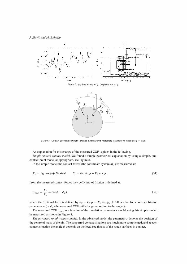
Figure 7. (a) time history of ϕ, (b) phase plot of ϕ.
Figure 8. Contact coordinate system (nt) and the measured coordinate system (xy). Note: cos φ = s/R.
An explanation for this change of the measured COF is given in the following.Simple smooth contact model. We found a simple geometrical explanation by using a simple, one-
contact-point model as appropriate, see Figure 8.In the simple model the contact forces (the coordinate system nt) are measured as:
Fx = FN cos φ + FT sin φ Fy = FN sin φ − FT cos φ. (31)
From the measured contact forces the coefficient of friction is defined as:
μxy,G = Fx
Fy= cot(φ − φμ), (32)
where the frictional force is defined by FT = FN μ = FN tan φμ. It follows that for a constant frictionparameter μ (or φμ) the measured COF will change according to the angle φ.
The measured COF μxy,G as a function of the translation parameter s would, using this simple model,be measured as shown in Figure 8.
The advanced rough-contact model. In the advanced model the parameter s denotes the position ofthe centre of mass of the pin. The concurred contact situations are much more complicated, and at eachcontact situation the angle φ depends on the local roughness of the rough surfaces in contact.
Simulating Multibody Dynamics with Rough Contact Surfaces and Run-in Wear
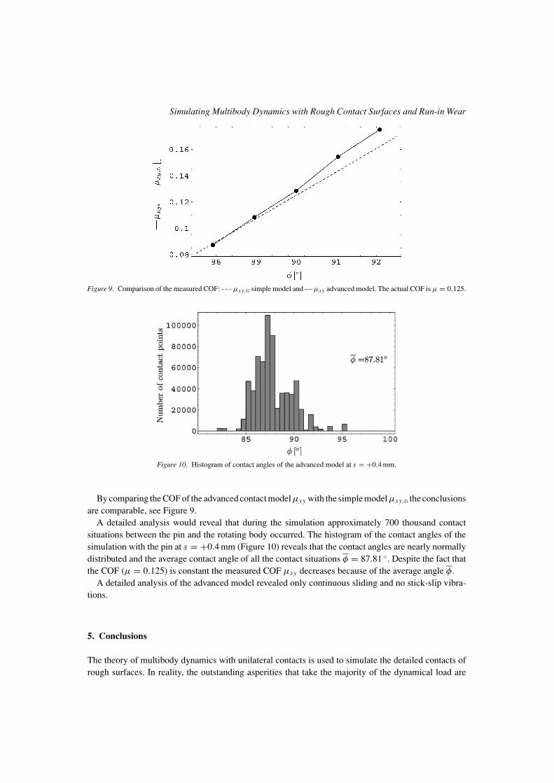
Figure 9. Comparison of the measured COF: - - - μxy,G simple model and — μxy advanced model. The actual COF is μ = 0.125.
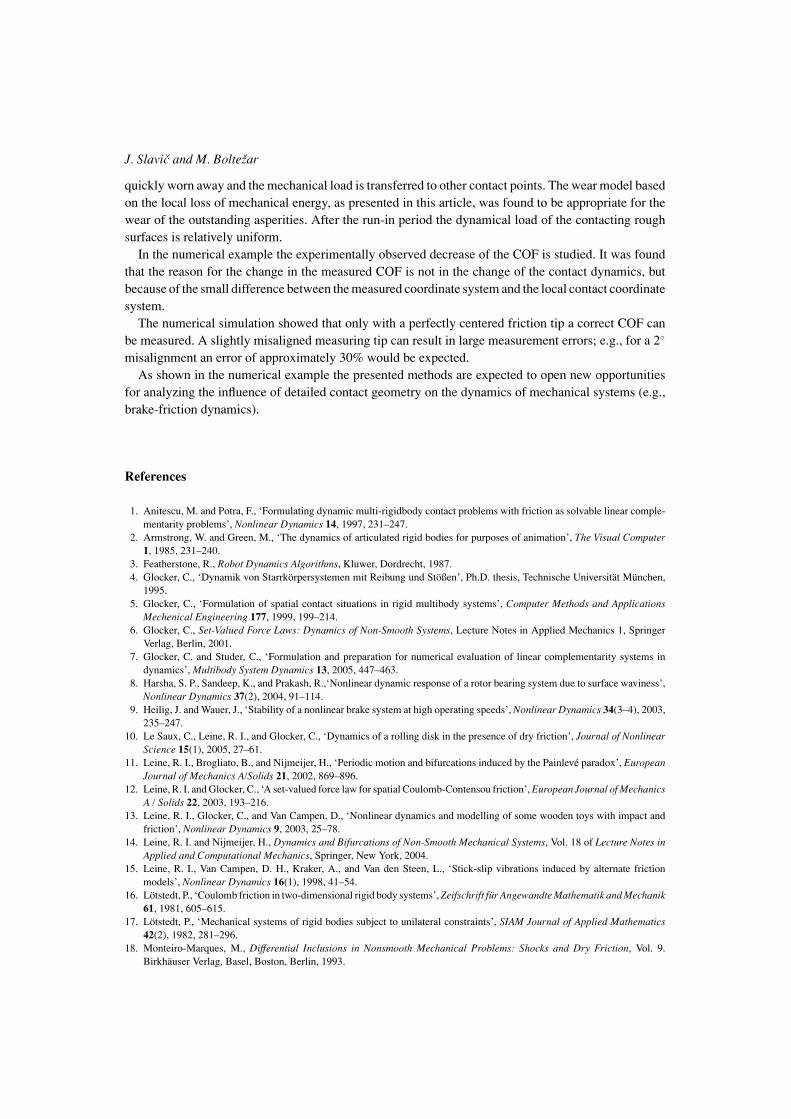
Figure 10. Histogram of contact angles of the advanced model at s = +0.4 mm.
By comparing the COF of the advanced contact modelμxy with the simple modelμxy,G the conclusionsare comparable, see Figure 9.
A detailed analysis would reveal that during the simulation approximately 700 thousand contactsituations between the pin and the rotating body occurred. The histogram of the contact angles of thesimulation with the pin at s = +0.4 mm (Figure 10) reveals that the contact angles are nearly normallydistributed and the average contact angle of all the contact situations φ = 87.81 ◦. Despite the fact thatthe COF (μ = 0.125) is constant the measured COF μxy decreases because of the average angle φ.
A detailed analysis of the advanced model revealed only continuous sliding and no stick-slip vibra-tions.
5. Conclusions
The theory of multibody dynamics with unilateral contacts is used to simulate the detailed contacts ofrough surfaces. In reality, the outstanding asperities that take the majority of the dynamical load are
J. Slavic and M. Boltezar
quickly worn away and the mechanical load is transferred to other contact points. The wear model basedon the local loss of mechanical energy, as presented in this article, was found to be appropriate for thewear of the outstanding asperities. After the run-in period the dynamical load of the contacting roughsurfaces is relatively uniform.
In the numerical example the experimentally observed decrease of the COF is studied. It was foundthat the reason for the change in the measured COF is not in the change of the contact dynamics, butbecause of the small difference between the measured coordinate system and the local contact coordinatesystem.
The numerical simulation showed that only with a perfectly centered friction tip a correct COF canbe measured. A slightly misaligned measuring tip can result in large measurement errors; e.g., for a 2◦
misalignment an error of approximately 30% would be expected.As shown in the numerical example the presented methods are expected to open new opportunities
for analyzing the influence of detailed contact geometry on the dynamics of mechanical systems (e.g.,brake-friction dynamics).
References
1. Anitescu, M. and Potra, F., ‘Formulating dynamic multi-rigidbody contact problems with friction as solvable linear comple-mentarity problems’, Nonlinear Dynamics 14, 1997, 231–247.
2. Armstrong, W. and Green, M., ‘The dynamics of articulated rigid bodies for purposes of animation’, The Visual Computer1, 1985, 231–240.
3. Featherstone, R., Robot Dynamics Algorithms, Kluwer, Dordrecht, 1987.4. Glocker, C., ‘Dynamik von Starrkorpersystemen mit Reibung und Stoßen’, Ph.D. thesis, Technische Universitat Munchen,
1995.5. Glocker, C., ‘Formulation of spatial contact situations in rigid multibody systems’, Computer Methods and Applications
Mechenical Engineering 177, 1999, 199–214.6. Glocker, C., Set-Valued Force Laws: Dynamics of Non-Smooth Systems, Lecture Notes in Applied Mechanics 1, Springer
Verlag, Berlin, 2001.7. Glocker, C. and Studer, C., ‘Formulation and preparation for numerical evaluation of linear complementarity systems in
dynamics’, Multibody System Dynamics 13, 2005, 447–463.8. Harsha, S. P., Sandeep, K., and Prakash, R.,‘Nonlinear dynamic response of a rotor bearing system due to surface waviness’,
Nonlinear Dynamics 37(2), 2004, 91–114.9. Heilig, J. and Wauer, J., ‘Stability of a nonlinear brake system at high operating speeds’, Nonlinear Dynamics 34(3–4), 2003,
235–247.10. Le Saux, C., Leine, R. I., and Glocker, C., ‘Dynamics of a rolling disk in the presence of dry friction’, Journal of Nonlinear
Science 15(1), 2005, 27–61.11. Leine, R. I., Brogliato, B., and Nijmeijer, H., ‘Periodic motion and bifurcations induced by the Painleve paradox’, European
Journal of Mechanics A/Solids 21, 2002, 869–896.12. Leine, R. I. and Glocker, C., ‘A set-valued force law for spatial Coulomb-Contensou friction’, European Journal of Mechanics
A / Solids 22, 2003, 193–216.13. Leine, R. I., Glocker, C., and Van Campen, D., ‘Nonlinear dynamics and modelling of some wooden toys with impact and
friction’, Nonlinear Dynamics 9, 2003, 25–78.14. Leine, R. I. and Nijmeijer, H., Dynamics and Bifurcations of Non-Smooth Mechanical Systems, Vol. 18 of Lecture Notes in
Applied and Computational Mechanics, Springer, New York, 2004.15. Leine, R. I., Van Campen, D. H., Kraker, A., and Van den Steen, L., ‘Stick-slip vibrations induced by alternate friction
models’, Nonlinear Dynamics 16(1), 1998, 41–54.16. Lotstedt, P., ‘Coulomb friction in two-dimensional rigid body systems’, Zeifschrift fur Angewandte Mathematik and Mechanik
61, 1981, 605–615.17. Lotstedt, P., ‘Mechanical systems of rigid bodies subject to unilateral constraints’, SIAM Journal of Applied Mathematics
42(2), 1982, 281–296.18. Monteiro-Marques, M., Differential Inclusions in Nonsmooth Mechanical Problems: Shocks and Dry Friction, Vol. 9.
Birkhauser Verlag, Basel, Boston, Berlin, 1993.
Simulating Multibody Dynamics with Rough Contact Surfaces and Run-in Wear
19. Moreau, J.-J., Unilateral Contact and Dry Friction in Finite Freedom Dynamics, Nonsmooth Mechanics and Applications.Springer-Verlag, Vienna, New York. International Centre for Mechanical Sciences, Courses and Lectures 302, 1988, pp.1–82.
20. Oden, J. and Martins, J., ‘Models and computational methods for dynamic friction phenomena’, Computer Methods InApplied Mechanics And Engineering 52(1–3), 1985, 527–634.
21. Paoli, L. and Schatzman, M., ‘Mouvement a un nombre fini de degres de liberte avec contraintes unilaterales: Cas avec perted’energie’, Mathematical Modeling and Numerical Analysis 27, 1993a, 673ñ–717.
22. Paoli, L. and Schatzman, M., ‘Vibrations avec contraintes unilaterales et perte d’energie aux impacts, en dimension finie’,Comptes Rendus de l’Academie des Sciences Paris Ser. I 317, 1993b, 97ñ–101.
23. Pfeiffer, F. and Glocker, C., Multibody Dynamics with Unilateral Contacts, John Wiley & Sons, Inc, New York, 1996.24. Rossmann, T. and Glocker, C., ‘Efficient algorithms for non-smooth dynamics’, in ASME International Mechanical Engi-
neering Congress and Exposition, Dallas, TX, 1997.25. Slavic, J. and Boltezar, M., ‘Nonlinearity and non-smoothness in multi body dynamics: Application to woodpecker toy’,
Journal of Mechanical Engineering Science, in press, 2005.26. Stewart, D., ‘Rigid-body dynamics with friction and impact’, SIAM Review 42(1), 2000, 3–39.27. Stewart, D. and Trinkle, J., ‘An implicit time-stepping scheme for rigid body dynamics with inelastic collisions and coulomb
friction’, Journal of Numerical Methods Engineering 39, 1996, 2673–2691.28. Tabor, D., ‘Friction-The present state of our understanding’, Journal of Lubrication Technology (183), 1981, 169–179.29. Vereshchagin, A., ‘Computer simulation of the dynamics of complicated mechanisms of robot manipulations’, Engineering
Cybernetics 6, 1974, 65–70.30. Wosle, M. and Pfeiffer, F., ‘Dynamics of spatial structure-varying rigid multibody systems’, Archive of Applied Mechanics
69(4), 1991, 265–285.31. Zhao, X., Reddy, C., and Nayfeh, A., ‘Nonlinear dynamics of an electrically driven impact microactuator’, Nonlinear
Dynamics 40(3), 2005, 227–239.