Embed Size (px)
Citation preview

Simple Pre-Feasibility of Biogas Projects
February 2015
Ministry of Energy and Petroleum

Attachment L-2 Simple Pre-FS of Biogas Projects
-2-
Table of Contents
Table of Contents .................................................................................................................................. 2
List of Tables ...................................................................................................................................... 3
List of Figures ...................................................................................................................................... 4
CHAPTER 1 OBJECTIVE OF PRE-F/S ........................................................................................ 6 1.1 Introduction.............................................................................................................................. 6 1.2 Biogas Project and Pre-F/S ...................................................................................................... 6
CHAPTER 2 METHODOLOGY OF PRE-F/S............................................................................... 8 2.1 System Model .......................................................................................................................... 8 2.2 Methodology of Pre-F/S .......................................................................................................... 8
CHAPTER 3 SUMMARY RESULT OF SURVEY OF SIX CANDIDATE SITES .................... 11
CHAPTER 4 SITE SURVEY RESULT ......................................................................................... 13 4.1 Site Survey of Nyeri High School ......................................................................................... 13
4.1.1 Purpose of the Project of Nyeri High School ................................................................. 13 4.1.2 Particular Features of Nyeri High School ...................................................................... 13 4.1.3 Preliminary Design......................................................................................................... 14 4.1.4 Energy Production and Demand Assessment of Nyeri High School ............................... 15 4.1.5 Benefit Assessment of Nyeri High School ..................................................................... 16
4.2 Rware High School ................................................................................................................ 16 4.2.1 Purpose of the Project of Rware High School ................................................................ 16 4.2.2 Particular Features of the School of Rware High School ............................................... 16 4.2.3 Preliminary Design of Rware High School .................................................................... 17 4.2.4 Energy Production and Demand Assessment of Rware High School ............................ 17 4.2.5 Benefit Assessment of Rware High School .................................................................... 18
4.3 Litein High School ................................................................................................................. 18 4.3.1 Purpose of the Project and Justification of Selection of Litein High School ................. 18 4.3.2 Particular Features of the School of Litein High School................................................ 18 4.3.3 Preliminary Design of Litein High School ..................................................................... 19 4.3.4 Energy Production and Demand Assessment of Litein High School ............................. 19 4.3.5 Benefit Assessment of Litein High School .................................................................... 20
4.4 Kipsigis Girls High School .................................................................................................... 20 4.4.1 Purpose of the Project and Justification of Selection of Kipsigis Girls High School .... 20 4.4.2 Particular Features of the School of Kipsigis Girls High School ................................... 21 4.4.3 Preliminary Design of Kipsigis Girls High School ........................................................ 21 4.4.4 Energy Production and Demand Assessment of Kipsigis Girls High School ................ 22 4.4.5 Benefit Assessment of Kipsigis Girls High School ........................................................ 22
4.5 Mukumu Girls High School ................................................................................................... 23 4.5.1 Purpose of the Project and Justification of Selection of Mukumu Girls High School ....... 23
4.5.2 Particular Features of the School of Mukumu Girls High School ................................. 23 4.5.3 Preliminary Design of Mukumu Girls High School ....................................................... 23 4.5.4 Energy Production and Demand Assessment of Mukumu Girls High School ............... 24 4.5.5 Benefit Assessment ........................................................................................................ 25
4.6 Cardinal Otunga High School ................................................................................................ 26 4.6.1 Purpose of the Project and Justification of Selection of Cardinal Otunga High School 26 4.6.2 Particular Features of the School of Cardinal Otunga High School ............................... 26 4.6.3 Preliminary Design of Cardinal Otunga High School .................................................... 26 4.6.4 Energy Production and Demand Assessment of Cardinal Otunga High School ............ 27 4.6.5 Benefit Assessment of Cardinal Otunga High School ................................................... 28 4.6.6 Benefit Assessment of Cardinal Otunga High School ................................................... 29

Attachment L-2 Simple Pre-FS of Biogas Projects
-3-
CHAPTER 5 COST ESTIMATION AND ECONOMIC/FINANCIAL EVALUATION FOR SIX BIOGAS PROJECTS ................................................................................................................. 29
5.1 Cost Estimation ...................................................................................................................... 29 5.2 Financial Evaluation .............................................................................................................. 31 5.3 Economic Evaluation ............................................................................................................. 32
CHAPTER 6 OPTION STUDY FOR NYERI HS ........................................................................ 34 6.1 Background ............................................................................................................................ 34 6.2 Cost Estimation ...................................................................................................................... 34 6.3 Demand in Nyeri HS ............................................................................................................. 35 6.4 Financial and Economic Benefit ............................................................................................ 35 6.5 Conclusion ........................................................................................................................... 36
Annex-1 BoQ and Scope of Works of Nyeri Biogas Project
Annex-2 Scope of Work of Feasibility Study of Nyeri Biogas Project
Annex-3 Drawing of Nyeri Biogas Project
Drawing No. N-01-1 Flow of Biogas System Option-1 Cooking Fuel Supply Only
Drawing No. N-01-2 Flow of Biogas System Option-2 with Generation System
Drawing No. N-02 Excavation Plan for Biogas Digester (32, 60 m3)
Drawing No. N-03-1 AKUT Fixed Dome Type Biogas Digester (32 m3) for Cow Dung
Drawing No. N-03-2 AKUT Fixed Dome Type Biogas Digester (60 m3) for Cow Dung
Drawing No. N-04 Control Chamber and Water Trap
Drawing No. N-05 Reinforcement Plan and Digester Manhole
List of Tables
Table 2.1 Economic Benefit ....................................................................................................................... 11 Table 3.1 Summary Result of Site Survey of Six Biogas Project Sites ..................................................... 12 Table 4.1 Estimation of Cow Dung Digester for Nyeri High School ........................................................ 14 Table 4.2 Estimation of Human Waste Digester for Nyeri High School .................................................... 14 Table 4.3 Estimation of Biogas Usage for Electricity and Fuel Wood Saving ........................................... 16 Table 4.4 Estimation of Benefit for Biogas System Installation ................................................................ 16 Table 4.5 Estimation of Cow Dung Digester for Rware School ................................................................ 17 Table 4.6 Estimation of Fuelwood Saving for Rware High School ........................................................... 18 Table 4.7 Estimation of Benefit for Biogas System Installation ................................................................ 18 Table 4.8 Estimation of Cow Dung Digester for Litein High School ........................................................ 19 Table 4.9 Estimation of Human Waste Digester for Litein High School ................................................... 19 Table 4.10 Estimation of Biogas Usage for Electricity and Fuel Wood Saving ......................................... 20 Table 4.11 Estimation of Benefit for Biogas System Installation .............................................................. 20 Table 4.12 Estimation of Cow Dung Digester for Kipsigis Girls High School ......................................... 21 Table 4.13 Estimation of Human Waste Digester for Kipsigis Girls High School .................................... 22 Table 4.14 Estimation of Biogas Usage for Electricity and Fuel Wood Saving ......................................... 22 Table 4.15 Estimation of Benefit for Biogas System Installation .............................................................. 23 Table 4.16 Estimation of Cow Dung Digester for Mukumu Girls High School ........................................ 24 Table 4.17 Estimation of Human Waste Digester for Mukumu Girls High School ................................... 24 Table 4.18 Estimation of Biogas Usage for Electricity and Fuel Wood Saving ......................................... 25 Table 4.19 Estimation of Benefit for Biogas System Installation .............................................................. 25 Table 4.20 Estimation of Cow Dung Digester for Cardinal Otunga Girls High School ............................ 27 Table 4.21 Estimation of Human Waste Digester for Cardinal Otunga High School ................................ 27 Table 4.22 Estimation of Biogas Usage for Electricity and Fuel Wood Saving ......................................... 28

Attachment L-2 Simple Pre-FS of Biogas Projects
-4-
Table 4.23 Estimation of Benefit for Biogas System Installation .............................................................. 28 Table 4.24 Estimation of Biogas Usage for Electricity and Fuel Wood Saving ......................................... 29 Table 4.25 Estimation of Benefit for Biogas System Installation .............................................................. 29 Table 5.1 Reference Values for the Cost Estimation .................................................................................. 30 Table 5.2 Result of the Cost Estimation ..................................................................................................... 31 Table 5.3 Summary for Financial Evaluation ............................................................................................ 32 Table 5.4 Economic Benefit ....................................................................................................................... 32 Table 5.5 Summary of Economic Evaluation ............................................................................................ 34 Table 6.1 Cost Estimation of Nyeri HS with/Without Generator ............................................................... 35 Table 6.2 Financial and Economic Evaluation with/without Generator .................................................... 36 Table 6.3 Value of Biogas for Fuel wood and Electricity Replacement ..................................................... 36
List of Figures
Figure 1.1 Project Flow ............................................................................................................................... 7 Figure 2.2 Flow of Pre-Feasibility Study ..................................................................................................... 9 Figure 4.1 Structure of Nyeri High School ................................................................................................ 14 Figure 4.2 Layout of Nyeri Biogas Plan .................................................................................................... 15 Figure 4.3 Structure of Rware High School ............................................................................................... 17
The source of all figures and tables is JICA Expert Team, otherwise specified.

Attachment L-2 Simple Pre-FS of Biogas Projects
-5-
List of Terms and Abbreviations
Abbreviation Description
AC Alternating Current EIA Environmental Impact Assessment ERC Energy Regulatory Commission
GIZ Deutsche Gesellschaft für Internationale Zusammenarbeit (German Society for International Cooperation)
GoK Government of Kenya HH Household Hivos Humanist Institute for Development Cooperation IEE Initial Environmental Examination JICA Japan International Cooperation Agency KPLC Kenya Power and Lighting Company Ltd. KSh Kenya Shilling (1US$ = 82.76 KSh, as of 1 September 2012) LED Light Emitting Diode LPG Liquefied Petroleum Gas MoE&P Ministry of Energy and Petroleum NEMA National Environment Management Authority NGO Non-Governmental Organization O&M Operation and Maintenance PPR Polypropylene PSDA Promotion of Private Sector Development in Agriculture PVC Polyvinyl Chloride RE Renewable Energy REA Rural Electrification Authority RT Retention Time
SNV Stichting Nederlandse Vrijwilligers (Netherlands Development Organization)
ToR Terms of Reference USD US Dollar WB World Bank
List of Electrical Terminology
A (Ampere) Unit of current V (Volt) Unit of voltage
kV (kilovolt) 1,000 volts W (Watt) Unit of active power kW (kilowatt) 1,000 watts MW (Megawatt) 1,000kW Wh (Watt-hour) Unit of energy kWh (kilowatt-hour) 1,000Wh MWh (Megawatt-hour) 1,000kWh

Attachment L-2 Simple Pre-F/S of Biogas Projects
-6-
CHAPTER 1 OBJECTIVE OF PRE-F/S
1.1 Introduction
Biogas is a combustible gas produced by the fermentation of organic material in the absence of oxygen. It is composed of approx. 60 percent of methane (CH4) and 40 percent carbon dioxide (CO2). It has a faint, unpleasant smell. It burns with a hot blue flame and can be used in gas lamps, cooking stoves, to generate electricity and to power diesel and petrol engines, among other applications (Hankins, 1987). The production of biogas requires the use of carbohydrates, proteins and/or fats. The actual reactants, however, are soluble organic matter, volatile fatty acids (mainly acetic acid), amino acid, long chain fatty acids, organic sulfur and ammonium compounds. These are found in food processing effluents, weeds, leaves, non-edible starch and in sewage, municipal and other waste (Dutt and Ravindranath, 1993).
The biogas production process occurs in the digester, which can be divided into two main groups; batch digesters and continuous flow digesters. Batch digestion is the simplest method to adopt for biogas systems. The plant is filled with substrate material and suitably inoculated to enable appropriate bacterial population to predominate. At the completion of the digestion (when gas falls to low levels) the material is removed and replaced with a new batch. After biogas is obtained, slurry (digested material) remains and can be used as compost manure (Ellegard, 1990).
As with other combustible gases, the dangers of explosion exist. When replacement of worn biogas installations is not carried out promptly, gas pipe might burst. Hydrogen sulfide (H2S) produced has a foul smell, poisonous and corrosive. Biogas slurry that is not properly handled can be environmentally harmful.
Although those issues should be noted for actual implementation, biogas can substitute fuel wood and facilitate decentralized electricity generation in areas with no access to the power grid. Biogas enables energy supply at low cost and waste utilization as fertilizer in rural areas
1.2 Biogas Project and Pre-F/S
Japan International Cooperation Agency (JICA) implemented the “Project for Establishment of Rural Electrification Model using Renewable Energy in Kenya” in 2012-2015. The project has two main components; (i) pilot projects for solar PV systems, and (ii) technical assistance for wind, small hydro, and biomass/biogas. This Guideline for Biogas Generation is prepared within the scope of the project by a Working Group (WG) of JICA Expert Team of Nippon Koei Co., Ltd /KRI in cooperation with Rural Electrification Authority (REA) in Kenya.
A biogas generation system is a method of electricity generation utilizing biogas produced by methane bacteria as the energy source. Similar to natural gas or propane gas, biogas has heat value, and can therefore be utilized as energy. Although the unit heat value of biogas is smaller than that of fossil fuels, biogas can be used as a cooking fuel in the same way as LPG with some modification of cooking stoves. When it is connected to a gas engine or modified diesel engine, it provides rotative force for the generator, producing electricity.
Since waste materials are used as feedstock for biogas systems and no fossil fuel is required, biogas is considered a renewable energy source.
Strategic Master Plan 2013/2014-2017/2018 of Rural Electrification Authority (REA), Third Draft, stipulates that promotion of the use of renewable energy sources including biomass is one of REA’s roles. In the strategic objective to develop and promote renewable energy sources, the strategic plan includes a target to develop and promote biogas and biomass systems for institutions and households.

Attachment L-2 Simple Pre-F/S of Biogas Projects
-7-
Pre-Feasibility Study for Biogas Projects is therefore prepared to assess the technical and economic feasibility of biogas projects in six schools in Kenya by the Working Group REA and JICA Expert Team.
It is important to evaluate the project feasibility for the project. There are many renewable energy projects that were conducted without sufficient survey and study of economic and financial feasibility. The general project flow is as shown in the figure below.
Prepared by JET
Figure 1.1 Project Flow
Simple Pre-feasibility study (Pre-F/S) was conducted for six REA biogas candidate project sites. The simple pre-F/S covers following items.
1) Outline and Purpose
2) Particular Features
3) Preliminary Design
4) Energy Production and Demand Assessment
5) Benefit Assessment
6) Cost Estimation
7) Economic/Financial Evaluation
8) Optional Study for the selected Project
For the selected project (Nyeri High School), optional study was conducted to select optimal biogas system component.
Above items are required in the proposal of REA management for project implementation.
Preliminary information collection
Conducting site survey
Preparation of Pre-F/S and F/S
User is willing to conduct?
Feedstock is available?
Feasible?
Design and preparation of specification
Tender process
Procedure for environmental clearance
Contract
Construction supervision
User training
Operation and maintenance
Evaluation
Yes
Yes
Yes
Proj
ect n
ot p
ossi
ble
No
No
No

Attachment L-2 Simple Pre-F/S of Biogas Projects
-8-
CHAPTER 2 METHODOLOGY OF PRE-F/S
2.1 System Model
Biogas system in public facility such as school with dormitory or prisons has advantages in terms of the following:
- Human waste is collective with sewer system and septic tank
- Generally schools have dormitory and own cows for milk supply. Cow dung is the best source of biogas in terms of organic composition and inherent methane producing bacteria.
The biogas system model in facilities such as schools is proposed as in Figure 1.
Figure 2.1 Basic Concept of Biogas System
The outline of the system is as follows:
1) Human waste is collected in septic tank. Biogas digester is installed between toilet and septic tank. Effluent from digester will enter existing septic tank. After methane production, solid waste, BOD, and pathogens will be reduced in the digester, and organic load to septic tank is reduced by the digester.
2) Cow dung from cow shed is collected in a digester through a trench. After degradation and methane production in a digester, effluent can be used as fertilizer to increase yield of garden vegetables and feed. The feed will be supplied to cows. This enables material cycle while producing biogas energy.
3) Biogas produced in digesters are collected once in gas bag, and can be used either/both generation by biogas generator or/and cooking stove.
Using above system model, simple pre-feasibility study (pre-F/S) was conducted for six biogas candidate project sites found by Rural Electrification Authority (REA). An optional study was conducted to select optimal biogas system components for the selected project (Nyeri High School) out of six target schools.
2.2 Methodology of Pre-F/S
The simple pre-F/S clarified the following: 1) Outline and Purpose, 2) Particular Features, 3) Preliminary Design, 4) Energy Production and Demand Assessment, 5) Benefit Assessment, 6) Cost Estimation, 7) Economic/Financial Evaluation , and 8) Optional Study for the selected Project for selected site. The work flow of the pre-F/S is shown in the figure below.
Toilet of Schooldormitory
Septic tank
GasBag
Biogasdigester
Biogas digester
Biogas Generator
Cooking stoveField
Effluent
Red text: installed by the project
Cowshed
Attachment L-2 Simple Pre-F/S of Biogas Projects
-9-
Prepared by JET
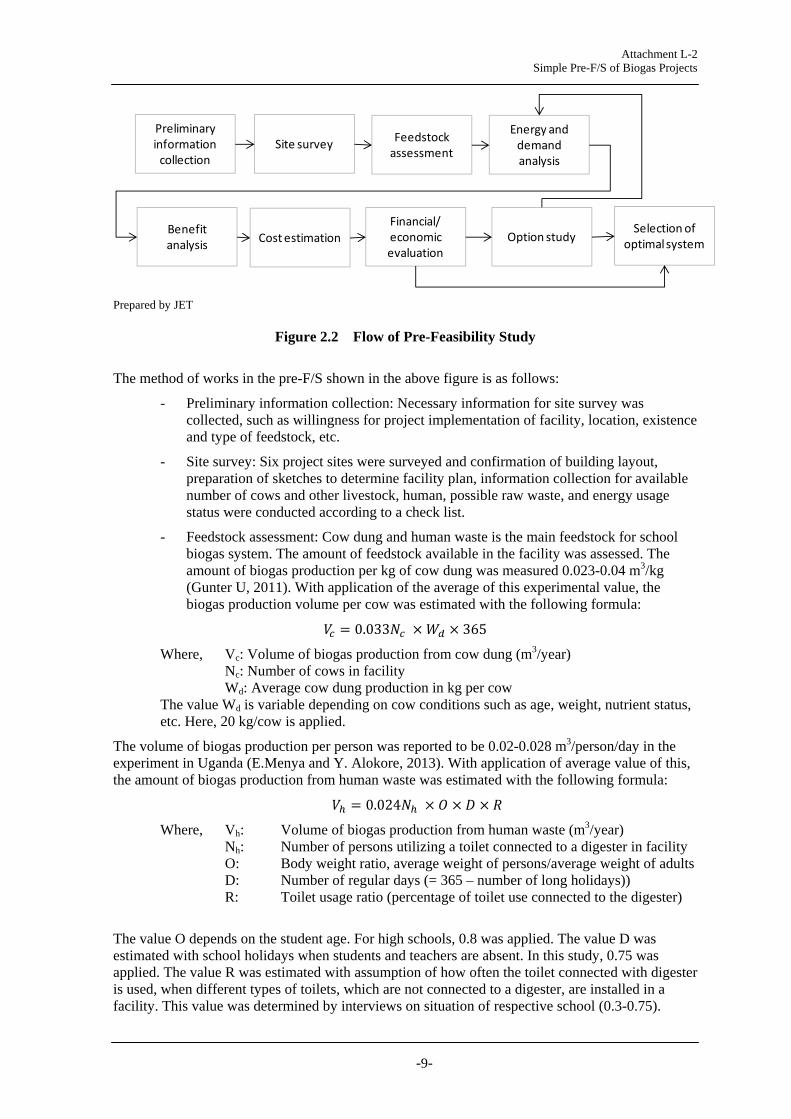
Figure 2.2 Flow of Pre-Feasibility Study
The method of works in the pre-F/S shown in the above figure is as follows:
- Preliminary information collection: Necessary information for site survey was collected, such as willingness for project implementation of facility, location, existence and type of feedstock, etc.
- Site survey: Six project sites were surveyed and confirmation of building layout, preparation of sketches to determine facility plan, information collection for available number of cows and other livestock, human, possible raw waste, and energy usage status were conducted according to a check list.
- Feedstock assessment: Cow dung and human waste is the main feedstock for school biogas system. The amount of feedstock available in the facility was assessed. The amount of biogas production per kg of cow dung was measured 0.023-0.04 m3/kg (Gunter U, 2011). With application of the average of this experimental value, the biogas production volume per cow was estimated with the following formula:
0.033 365
Where, Vc: Volume of biogas production from cow dung (m3/year) Nc: Number of cows in facility Wd: Average cow dung production in kg per cow
The value Wd is variable depending on cow conditions such as age, weight, nutrient status, etc. Here, 20 kg/cow is applied.
The volume of biogas production per person was reported to be 0.02-0.028 m3/person/day in the experiment in Uganda (E.Menya and Y. Alokore, 2013). With application of average value of this, the amount of biogas production from human waste was estimated with the following formula:
0.024
Where, Vh: Volume of biogas production from human waste (m3/year) Nh: Number of persons utilizing a toilet connected to a digester in facility O: Body weight ratio, average weight of persons/average weight of adults D: Number of regular days (= 365 – number of long holidays)) R: Toilet usage ratio (percentage of toilet use connected to the digester)
The value O depends on the student age. For high schools, 0.8 was applied. The value D was estimated with school holidays when students and teachers are absent. In this study, 0.75 was applied. The value R was estimated with assumption of how often the toilet connected with digester is used, when different types of toilets, which are not connected to a digester, are installed in a facility. This value was determined by interviews on situation of respective school (0.3-0.75).
Preliminary informationcollection
Site survey Feedstockassessment
Energy and demand analysis
Cost estimationFinancial/economic evaluation
Benefitanalysis Option study
Selection of optimal system

Attachment L-2 Simple Pre-F/S of Biogas Projects
-10-
- Energy and demand analysis: Energy usage and energy demand in the target facility was assessed by collecting data of monthly electricity bills and amount of actual usage of fuel wood.
- Benefit analysis: The benefit of biogas system consists of fuel wood saving and electricity saving, and can be calculated by the amount of saved fuel wood and/or electricity. The benefit of fuel wood saving was calculated with the following formula:
/ ,
Where, Sf: Saved amount of fuel wood by biogas (tons/year) Vcw and Vhw : Biogas volume Vc and Vh allocated for cooking fuel saving (m3) Cgas: Calorific value of produced biogas (MJ/m3) Cwood: Calorific value of fuel wood (MJ/ton) Estove: Efficiency of cooking stove Bf: Benefit of fuel wood saving (Ksh) Pwood: Price of fuel wood (Ksh/ton) Here, calorific value of produced biogas 20 MJ/m3 (M. Kaltschmittm, 2003) was applied for Cgas. The calorific value of fuel wood, Cwood, is variable depending on moisture percentage and condition of wood. For dry wood, the value is indicated to be 0.019-0.0225 MJ/ton (Hubbard W., et al., 2007). The value of 0.02 is applied in this study. Estove value depends on the actual cooking stove type that the facility uses, and 10% (N.Shrestha, 2001) is applied for Estove here. Fuel wood price, Pwood, is also variable depending on local condition, and was set to be 3,300 kSh/ton from local interviews.
The benefit of electricity saving is calculated with the following formula.
, Where, Eg: Saved amount of electric energy (kWh)
Vce and Vhe : Volume of biogas Vc and Vh allocated for electricity saving (m3) Ge: Efficiency of biogas generator (kWh/m3) Be: Benefit of electricity saving (Ksh.) T: Power tariff rate (Ksh./kWh) The efficiency of biogas generator, Ge depends on specification of biogas engine generator. Here, 1.0 kWh/m3 was applied according to manufactures’ specification in the past project. T, tariff rate is determined with actual monthly bills of the respective facilities, which was 8.7-19.9 Ksh/kWh.
i) System design: System design layout was prepared according to sketches in the survey. The size of digester was determined with the following formula (Gunter U et al., 2011 and Martin G et al, 2012)
1.89 , 0.1
Where, Vdc: Volume of cow dung digester (m3) Vdh: Volume of human waste digester (m3)
The size of generator was determined according to required specific load demands such as water pump or lighting.
ii) Cost estimation: The cost of biogas system was estimated by unit cost estimation with quantity or capacity in the past result of REA biogas projects.
iii) Financial and Economic Evaluation: The financial benefit is the same as what was estimated in the benefit assessment. The total economic benefit Bteb is calculated with the following formula.
The meanings of respective benefit items are explained in the table below.

Attachment L-2 Simple Pre-F/S of Biogas Projects
-11-
Table 2.1 Economic Benefit
B Type of Economic Benefit Explanation
Beb Benefit as electricity saving from diesel oil
When electricity is generated using biogas, the electric energy can be considered to save electricity from grid-connected diesel generation system in grid, since diesel generation is the most expensive method. The cost of electricity from diesel generation can be considered as economic benefit in place of grid electricity tariff, different from financial benefit. Diesel Oil Price 110.00 KSh/L and Diesel efficiency 2.40 kWh/L was applied.
Bcr Benefit of carbon reduction by biogas generation
CO2 emission reduction is expected from biogas generation since it replaces energy from diesel generation. Emission factor of diesel oil can be applied to calculate economic benefit. Emission factor of electricity 0.81805 ton-CO2/MWh and 1,294 KSh/ton-CO2 was applied (with exchange rate 86.28 KSh/US$).
Bf Benefit from fuelwood saving The benefit is the same as financial benefit of fuel wood saving.
Bfab Fuelwood carbon absorption benefit
Saved fuel wood by biogas can absorb CO2 in a forest. The carbon credit with the absorption of CO2 amount is considered to be economic benefit.
Bfco Fuelwood carbon off-set benefit
As well as electricity, saved amount of fuelwood is considered to replace coal, and corresponding amount of CO2 from the replaced coal. This is considered to be economic benefit of carbon reduction.
Bfev Fuel wood economic value to prevent deforestation
Saving of losses in economic sectors resulting from deforestation is counted as economic benefit. The components of this economic value are: growing of crops and horticulture, fishing, water supply, public administration and defense, deforestation effects on carbon sequestration, and deforestation effects on health, which was quantified as much as 921,165 KSh/ha (Jackie C, 2012).
Prepared by JET
CHAPTER 3 SUMMARY RESULT OF SURVEY OF SIX CANDIDATE SITES
The result of site survey jointly prepared with REA staff is summarized in the following tables.

Attachment L-2 Simple Pre-F/S of Biogas Projects
-12-
Table 3.1 Summary Result of Site Survey of Six Biogas Project Sites
Prepared by JET
Unit Nyeri High School Rware High School Litein High SchoolDate of site survey 23 May 2013 23 May 2013 18 June 2013Location (County, sublocation, location, village) Nyeri County Nyeri County Rift Valley, KerichoCoordinate (Latitude, longitude, elevation) N°24.499', E36°55.159', EL1844m N°24.793', E36°57.323', EL1786m N 0°35' 21.8", E35°11'11.5", EL1944mDistance from Nairobi 168 km (paved, except last 1 km) 158 km (paved) 264 kmGrid connected?, Nearest grid connection in km Yes Yes YesFinanced by Missionary, government, PTA Government Missionary, GovernmentEstablishment year 1924 1985 1964
Nos of cows nos5 cows, 1 medium, 4 small, total 10.2 cows in different cow shed.Possible to increase.
9 cows 12 cows, zero-grazing, possible 5 more cows
Nos of pigs or nos of poultry nos NA NA noneNos of students (total) nos 950 students (all boarding) 400 boys, 200 girls, total 600 students 1015Nos of students (boarding, period of boarding) nos 950 students, 13 weeks leave/yr none (all daily students) 1015, 9 months/yrNos of teacher and staff nos 40 teaches and 30 non-teaching staff 25 teachers and 15 non-teaching staffs 53 teachers and 80 staffsNos of teacher (living) nos 40 teaches and 30 non-teaching staff NoneWater usage for toilet cleaning L/day, t/day 30 t/day
Garden or cultivation near the siteNapier(5acre), sweet potato(0.5acre),Maize(0.25acre), glass(2acre), Tilapia fish pondFeeding 2 t/day
bean, banana, grass land, total 2 acres Sukuma, egg plant, 1.5 acre
Electricity usage kWh/mon TBA Approx. 1000 kWh/moWater pump: 2,089 kWh (Feb-13)School: 663 kWh (Feb-13)
Electricity tariff payment record (invoice forseveral months)
Ksh/mon Ave. 130,000 Ksh/mo, 5000 kWh/mo149,931 KSh with 7,605 kWh (Mar 13)
8974 KSh with 1028 kWh (Feb 13) Water pump: 37,819 Ksh/m, 18.1 KSh/kWhSchool: 12,094 kWh/m, 18.2 KSh/kWh
Current use of electric/heat appliance (type, hours)Light, PC, mobile charge, TV, radio, cooking heater,other
General electric appliance, lightingTotal 59 nos of 36W FL bulb in dorm.
General administration, lighting, cooking.PC is planned to be installed. Light, PC, copier, Posho mill
Diesel generator and oil for generation, if any, cost L/day, L/mon 38.5 kVA, 480L/year None 20 kVA, temporary useType of fuel for cooking (Fuel wood, LPG, etc) Fuel wood, LPG (45kg/term) Fire wood. 7 fuel wood stovesCurrent usage of fuel wood, cost kg/day, t/mon 300 t/year, 792,857 KSh/year 42 t/term, 3300 Ksh/t -> 415,800Ksh/yr 300 kg/d, 88.2 t/yrCurrent usage of LPG, cost cylinder/mon TBA None Occasional for labCurrent usage of other fuel Boiler by firewood None NoneSource of water supply (pump, etc.) Municipal water, gravity from river 12 away Municipal water Water pump installed 700m away
Type of lighting Electricity Electricity CFL
Priority usage of gas (electricity, fuel, etc)1) cooking fuel, 2) lighting for dormitoryand night class
1) cooking fuel Fuel wood saving
Proposed digester size 32 m3 for cow dung, 60m3 for toilet 24 m3 x 1 32 m3 for cow dung, 60m3 for toiletProposed generation system 5 kW (7kVA) biogas generator NA (cooking fuel supply only) 15 kW (20 kVA) biogas generator
Other Remarks
Japanese assistance for Math and Science wastaken in 2004 through Min of Education.22 buildings of Teacher Quarter.
- Cow is zero-grazing. Cow shed with no trench islocated too far a way (300-400m). Move or longpipeline is necessary. - Toilet is pit latrine. Improvement to septic tankis necessary.- Capacity of pump needs to be confirmed
Confirmation Item
Unit Kipsigis Girls High School Mukumu Girls High School Cardinal Otunga High SchoolDate of site survey 18 June 2013 19 June 2013 19 June 2013Name of the facility Kipsigis Girls High School Mukumu Girls High School Cardinal Otunga High SchoolLocation (County, sublocation, location, village) Rift Valley, Kericho Western, Kakamega Nyanza, KisiiCoordinate (Latitude, longitude, elevation) N 0°22' 49.2", E35°14'58.8", EL1971m N 0°12' 56.9", E34°46'05.9", EL1533m N 0°12' 56.6", E34°46'05.3", EL1523m
Distance from Nairobi 265 km 430 km 385 kmGrid connected?, Nearest grid connection in km Yes Yes YesFinanced by Government Mission school Catholic sponsored mission schoolEstablishment year 1955 1959Nos of cows nos 4 cows, possible to increase, not zero-grazed 9 cows, not zero-grazed. 5-14:00 grazing. 8 cows, not zero-grazed (2-4pm grazing), 50 pigs
Nos of pigs or nos of poultry nos
Nos of students (total) nos 900 1248 1000Nos of students (boarding, period of boarding) nos 900 1248 1000Nos of teacher and staff nos 45 teachers and 42 staffs 63 teachers and 55 staffsNos of teacher (living) nos 18 teachers
OType of toilet Two septic tanks (2.5x6m, 3x9m) Septic tanks 4x10mPit latrine, new toilet with septic tankto be installed
Raw waste material (food, vegetable waste, etc) Kitchen vegetable waste Kitchen vegetable waste
Electricity usage kWh/mon 4,472 kWh (May-13)School:2,791 kWh (May-13)Pump: 2,954 kWh (May-13)
School:1519 kWh (Apr-13)Pump: 598 kWh (Apr-13)
Electricity tariff payment record (invoice for severalmonths)
Ksh/mon 86,968 KSh (May-13), 19.5 KSh/kWhSchool: 49,983 Ksh(May-13), 17.9 KSh/kWhPump:52,894 KSh (May-13), 17.9 KSh/kWh
School: 30,212 Ksh(Apr-13), 19.9 KSh/kWhPump:11,746kSh (Apr-13), 19.6 KSh/kWh
Current use of electric/heat appliance (type, hours) Light,PC, mobile charge, TV, radio, cooking heater, other
Light, 11 PCs , copier, kettle Light, PC, copier, Printer, 2 fridges, water pump Light, PC, copier, Posho mill
Diesel generator and oil for generation, if any, cost L/day, L/mon Available in the past. Power house available. DG installed. 13.5 kVA 52 kW, automatic changeover for blackout
Type of fuel for cooking (Fuel wood, LPG, etc) 6 fuel wood stoves, 1 middle stove 13 fuelwood stoves, 2 charcoal stoves 6 firewood stovesCurrent usage of fuel wood, cost kg/day, t/mon 2 tractors/d 50 tons/yr, 225,000 KSh/year 1 mil Ksh/yr in 2011. Now self supplyCurrent usage of LPG, cost cylinder/mon Lab use only Labs and home science, 26,000 KSh/term LabCurrent usage of other fuel None Charcoal 20x50kg/term, Dec 15x50/m, 1000Ksh/50kg None
Source of water supply (pump, etc.) Municipal water (no pump) Water pump installed in 1999. 20hp or 20 kW Water pump. Water tank tower installed.
Type of lighting CFL CFL CFLPriority usage of gas (electricity, fuel, etc) Fuel wood and electricity Fuel wood and electricity Fuel wood and electricityProposed digester size 16 m3 for cow dung, 50m3 for toilet 28 m3 for cow dung, 60m3 for toilet 32 m3 for cow dung, 60m3 for toiletProposed generation system
Other Remarks
-Strategic Plan 2010-14 includes introductionof biogas.- Willingness is high and ready for project- Dormitory lighting: 13 dorms buildings(13x40W FL+ 2x8W FL/dorm). 21:30-4:00- 20nos classroom, 3 labs, 1 PC room- All toilets are collected to same septic tank
- Discharge pipe for Bath room and Toilet are same.It needs separation.- Outside pit latrine is used for daytime- Cows possible to increase up to 15.- Pump manager available for O&M.
- Toilet roof need replacement every 7 monthsdue to gas. Toilet 6 times/year drainage required,15,000 KSh each time.- Lighting required in 14 dorms- New dorm toilet will be installed in Dec 2013.- Land area 50 acres- Every Tuesday 2-9 pm blackout.
Confirmation Item

Attachment L-2 Simple Pre-F/S of Biogas Projects
-13-
According to the survey result, the following works were conducted in the basic planning with transferring methodology to the counterpart staff.
- Determination of biogas digester size
- Assumption of feedstock input amount
- Preparation of draft layout of the system
- Estimation of possible biogas production
- Determination of capacity of generator and possible amount of electric energy generation
- Estimation of possible firewood amount saving by biogas
- Calculation of financial benefit
- Cost estimation
- Financial analysis and economic analysis
CHAPTER 4 SITE SURVEY RESULT
4.1 Site Survey of Nyeri High School
4.1.1 Purpose of the Project of Nyeri High School
The School consumes large amount of both electricity and fuel wood to support life of children in boarding. Electricity is consumed especially for lighting of night class and boarding of students. Fuel wood is consumed at 300ton/year for daily meals for students and teachers. The financial burden of electricity is about 1.5 mil KSh/year and that of fuel wood is 0.8mil KSh/Year Electricity supply by biogas can contribute the mitigation of electricity and fuel wood usage in the school.
Nyeri High School has students from all over the country. Students can learn the effectiveness of biogas system. They can be a human resource for the promotion of renewable energy in Kenya.
The school has shown willingness to implement the project, including commitment to participate construction supervising and operation and maintenance.
4.1.2 Particular Features of Nyeri High School
The outline other than above table is as follows.
- The school was established as a missionary school in 1924, and reformed as high school in 1950’s.
- The school received Japanese ODA activity for mathematics and science in 2004 through Ministry of Education.
- All the 950 student stays in the school.
- Diesel generator was installed as a back up, it is however not used frequently.
- The school started fishpond project a few months ago rearing tilapia fingerlings. The school garden utilizes raw manure from the cowshed and grey water from the kitchen to grow nappier grass, maize and sweet potatoes
Organization structure is shown below.

Attachment L-2 Simple Pre-F/S of Biogas Projects
-14-
Prepared by JET
Figure 4.1 Structure of Nyeri High School
4.1.3 Preliminary Design
The demand for biogas is (i) cooking fuel and (ii) electricity for nighttime lighting in boarding buildings. The proposed system is as follows:
- Digester: 32 m3 for cow dung, 60m3 for toilet of boarding
- Generator : 5 kW (7 kVA), exclusive load for nighttime lighting in boarding (59 nos of 36W)
- Gas bag: 40 m3
- Total gas production: 12 m3 + 15 m3 = 27 m3/day
Table 4.1 Estimation of Cow Dung Digester for Nyeri High School
Prepared by JET
Table 4.2 Estimation of Human Waste Digester for Nyeri High School
Prepared by JET
Principal (1)
Vice Principal (1)
Teachers(40)
Non‐teachingStaffs(30)
Boardof Governner
PTA
Description Qty Unit RemarksNos of cows 17 to be increased from 10 nosDigester size 32 m3Assumed feedstock input 400 kg/dayPossible gas production 12 m3/dayGenerated energy 12 kWh 1kWh/m3Electric energy demand 8.5 kWh Light, 59 nos of 36W, 4hrs
Description Value UnitUtilization ratio 0.54 Boarding toilet usage ratio 0.67 Student/adult weight 0.80Nos of student utilizing dorm toilet 950 nosConverted nos of person for biogas 509 nosDigester volume 60 m3Gasproduction amount 15.3 m3/day

Attachment L-2 Simple Pre-F/S of Biogas Projects
-15-
- Digester for cow dung can be located at garden area below cow shed. It can utilize gravity flow to transport cow dung and urine. Supply of effluent to garden is also possible by gravity.
- Two digesters can be connected to one gasbag. The bag will supply the biogas to (i) cooking stove and (ii) biogas generator.
Prepared by JET
Figure 4.2 Layout of Nyeri Biogas Plan
4.1.4 Energy Production and Demand Assessment of Nyeri High School
The aspects of energy production and demand assessment are as follows.
- Firewood is purchased locally through tender. Consumption is about 300 ton/year which cost is approximately 0.8 mil KSh/year.
- The electricity consumption is about 5000 kWh/month and 130,000 KSh/month.
- It is planned to install digesters both for cooking fuel supply and electricity supply. lighting for class room is a stable load, which can be supplied by biogas generator.
- Total expected amount of gas production is 8,568 m3/year, of which 2,321 m3 is used for generation and 6,428m3 is used for cooking stove.
- Amount of electricity saving will be 2,321 kWh and amount of fuel saving will be 36.3 ton/year. This corresponds to 4% of total electricity usage and 12% of fuel wood.

Attachment L-2 Simple Pre-F/S of Biogas Projects
-16-
Table 4.3 Estimation of Biogas Usage for Electricity and Fuel Wood Saving
Prepared by JET
4.1.5 Benefit Assessment of Nyeri High School
The aspects of benefit assessment are as follows.
- When unit cost of electricity is 26 KSh/kWh, the annual saving will be 60,333 KSh/year for electricity.
- When unit cost of fuel wood is 3,300 KSh/ton, annual saving for fuel wood will be 119,717 KSh.
- In total, the annual benefit of biogas system will be 180,050 KSh/year.
Table 4.4 Estimation of Benefit for Biogas System Installation
Prepared by JET
4.2 Rware High School
4.2.1 Purpose of the Project of Rware High School
Rware High School is a day school. Large amount of fuel wood is consumed to offer meals for students and teachers. The school has shown interest in install biogas system to reduce the usage of fuel wood. They have a proposed design. Although it is located in town area, the size of the school is typical for rural area.
4.2.2 Particular Features of the School of Rware High School
The outline other than above table is as follows.
Item Value Unit NoteAnnual biogas production from cow dung 4,380 m3/yr 365 days, 12m3/dayAnnual biogas production from toilet 4,188 m3/yr 273 days, 15.3 m3/dayTotal amount of gas production 8,568 m3/yrBiogas used for generation energy 2,321 kWh/yr 273 days, 8.5 kWhBiogas used for cooking fuel 6,248 m3/yrCalorific value of biogas for cooking fuel 20 MJEfficiency of biogas stove 45 %Efficiency of fuelwood stove 10 %Calorific value of fuelwood 15.5 MJ /kgAmount of fuelwood reduction 36.3 ton/yr
Item Value UnitUnit cost of kWh electricity 26 KSh/kWhCost benefit of electricity saving 60,333 Ksh/yrUnit cost of ton fuelwood 3300 KSh/tonCost benefit of fuelwood saving 119,717 KShTotal benefit of biogas system 180,050 Ksh/yrUnit benefit per m3 for electricity 26.0 KSh/m3Unit benefit per m3 of fuelwood 19.2 KSh/m3

Attachment L-2 Simple Pre-F/S of Biogas Projects
-17-
- The school is day school and there is no boarding student. The nos of student is 600.
- Primary school is located behind the school.
- There is need to hire a operator from outside for biogas system operation.
- The structure of the school is shown below.
- Toilets are all pit latrine and there is no septic tank.
Prepared by JET
Figure 4.3 Structure of Rware High School
4.2.3 Preliminary Design of Rware High School
The demand for biogas is (i) cooking fuel and (ii) electricity. The consumption of the electricity in the school is about 1000 kWh and the unit cost of electricity is about 9 KSh/kWh. Since the tariff value for electricity is low, it is considered that benefit from electricity saving is small. Accordingly, the system will apply the biogas for cooking fuel only.
Girl’s toilet is located near the cow shed. Utilization of girl’s toilet is one option to increase amount of gas. However, if the effluent is directly used as the fertilizer of the garden, connection from the toilet is not recommended.
- Digester: 24 m3 for cow dung (gas bag type digester can also be considered)
- Gas bag: 20 m3
- Recommended application: biogas burner
Table 4.5 Estimation of Cow Dung Digester for Rware School
Prepared by JET
4.2.4 Energy Production and Demand Assessment of Rware High School
The aspects for energy production and demand assessment are as follows:
- Fuelwood is locally procured by tender at 3,300 KSh/ton.
- The annual biogas production is 3,285 m3. This corresponds to 19.1 ton of fuelwood when the efficiency of the current fuelwood stove is 10%.
Principal (1)
Vice Principal (1)
Headof Dept. (8)
Auditing Languag Science Math Humanity Technical Athretics Carieer
Boardof Governner
PTA
Description Qty Unit RemarksNos of cows 13 to be increased from 9 nosDigester size 24 m3Assumed feedstock input 300 kg/dayPossible gas production 9 m3/day

Attachment L-2 Simple Pre-F/S of Biogas Projects
-18-
Table 4.6 Estimation of Fuelwood Saving for Rware High School
Prepared by JET
4.2.5 Benefit Assessment of Rware High School
When unit cost of fuel wood is 3,300 KSh/ton, annual saving for fuel wood will be about 62,900 KSh.
Table 4.7 Estimation of Benefit for Biogas System Installation
Prepared by JET
4.3 Litein High School
4.3.1 Purpose of the Project and Justification of Selection of Litein High School
The school consumes large amount of fuel wood 300 kg/day or 88.2 ton/year and electricity as much as 12,000 kWh/month. The main load of electricity is water pump. The biogas system will be possible to reduce the consumption of fuel wood and electricity. Diesel engine is installed to supply electricity in the night time power cut, and biogas system could provide electricity during power cut.
4.3.2 Particular Features of the School of Litein High School
The particular features other than above table are as follows.
- The toilet are pit latrine and requires trench toilets to be re-constructed to obtain human waste as feed stock. Installation of septic tank will also be required, unless effluent is managed for supplying garden fertilizer.
- Cows are zero-grazed. The shed is located far away from load center. Shifting of cow shed near load center or 300-400m pipe or cable to transport gas or electricity is necessary. Cow shed has with no trench and its construction is required.
- 20 kVA Diesel generator is used occasionally. Fuel consumption per month is approximately 40litre.
- Water pump is installed 700 m away from the school. Voltage drop for this distance is a major concerned to supply from biogas system. Capacity of the pump is 5.5 hp
- Additional cost for toilet construction, long gas line pipes, and distribution line will be done. This will increase implementation cost.
Item Value Unit NoteAnnual biogas production from cow dung 3,285 m3/yr 365 days, 9m3/dayBiogas used for cooking fuel 3,285 m3/yrCalorific value of biogas for cooking fuel 20 MJEfficiency of biogas stove 45 %Efficiency of fuelwood stove 10 %Calorific value of fuelwood 15.5 MJ /kgAmount of fuelwood reduction 19.1 ton/yr
Item Value UnitUnit cost of ton fuelwood 3300 KSh/tonCost benefit of fuelwood saving 62,945 KShUnit benefit per m3 of fuelwood 19.2 KSh/m3

Attachment L-2 Simple Pre-F/S of Biogas Projects
-19-
4.3.3 Preliminary Design of Litein High School
The demand for biogas is (i) cooking fuel, (ii) electricity for nighttime lighting in boarding building, and (iii) water pump. The proposed system is as follows:
- Digester: 32 m3 for cow dung to supply electricity, 60m3 for boarding toilet to supply cooking fuel
- Generator : 20 kVA for pump (700 m away)
- Gas bag: 20 m3 + 20 m3
- Total gas production: 12 m3 (from cow) + 16 m3 (from toilet) = 28 m3/day
Table 4.8 Estimation of Cow Dung Digester for Litein High School
Prepared by JET
- Trench construction is necessary for connecting cowshed to digester.
- The digester is proposed to connect to biogas generator, which will provide to the water pump 700 m away from the school.
Table 4.9 Estimation of Human Waste Digester for Litein High School
Prepared by JET
New construction of septic tank and trench toilet is necessary. Effluent from human waste digester requires to connect to new septic tank, for easy management.
4.3.4 Energy Production and Demand Assessment of Litein High School
The energy and demand assessment of Litein HS is as follows:
Description Qty Unit RemarksNos of cows 17 nos 12cows, 5 to be added, zero-grazingDigester size 32 m3Assumed feedstock input 400 kg/dayPossible gas production 12 m3/dayGenerated energy 12 kWh 1kWh/m3Electric energy demand 40 kWh 20 kW x 2 hours
Description Value UnitUtilization ratio 0.54 Boarding toilet usage ratio 0.67 Student/adult weight 0.80Nos of student utilizing dorm toilet 1015 nosConverted nos of person for biogas 544 nosDigester volume 60 m3Gasproduction amount 16.3 m3/day

Attachment L-2 Simple Pre-F/S of Biogas Projects
-20-
- The electricity consumption for water pump is 2,089 kWh/month and for school is 663 kWh/month as of February 2013.
- Due to the proximity to the water pump, the digester using cowdung should generate electricity to pump water, while the one using the human waste should be constructed near the kitchen to supply for cooking fuel.
- Total expected amount of gas production is 8,846 m3/year, of which 4,380 m3 would be used for generation and 4,466 m3 for cooking stove.
- Amount of electricity saving will be 4.380 kWh/year and 25.9 ton/year fuel wood. This corresponds to 17% of total electricity usage and 29% of fuel wood saving in the school.
Table 4.10 Estimation of Biogas Usage for Electricity and Fuel Wood Saving
Prepared by JET
4.3.5 Benefit Assessment of Litein High School
The aspects of benefit assessment are as follows: - When unit cost of electricity is 18.1 KSh/kWh, the annual saving will be 79,278
KSh/year for electricity.
- When unit cost of fuel wood is 3,300 KSh/ton, annual saving for fuel wood will be 85,578 KSh.
- In total, the annual benefit of biogas system will be 164,856 KSh/year.
Table 4.11 Estimation of Benefit for Biogas System Installation
Prepared by JET
4.4 Kipsigis Girls High School
4.4.1 Purpose of the Project and Justification of Selection of Kipsigis Girls High School
The school in its 2010-14 strategic plan has proposed installation of biogas system in the school. This indicates a high sense of ownership for the project. The school requires nighttime dormitory lighting and to reduce fuel wood.
Item Value Unit NoteAnnual biogas production from cow dung 4,380 m3/yr 365 days, 12m3/dayAnnual biogas production from toilet 4,466 m3/yr 274 days, 16.3 m3/dayTotal amount of gas production 8,846 m3/yrBiogas used for generation energy 4,380 kWh/yr from electricity bill Feb-13
Biogas used for cooking fuel 4,466 m3/yrCalorific value of biogas for cooking fuel 20 MJEfficiency of biogas stove 45 %Efficiency of fuelwood stove 10 %Calorific value of fuelwood 15.5 MJ /kgAmount of fuelwood reduction 25.9 ton/yr
Item Value Unit NoteUnit cost of ton fuelwood 3300 KSh/ton Not known in this schoolUnit cost of unit electricity 18.1 KSh/kWh from electricity bill Feb-13
Benefit of saving electricity 79,278 KSh/yrBenefit of fuel wood saving 85,578 KSh/yrTotal benefit 164,856 KSh/yr

Attachment L-2 Simple Pre-F/S of Biogas Projects
-21-
4.4.2 Particular Features of the School of Kipsigis Girls High School
The particular features other than above table are as follows.
- The school has 13 blocks of dormitory and requires 13 nos x 40W Fluorescent Light and 2 x 8W Fluorescent Light for each building. This is the major requirement for electricity supply.
- The school has 20 number of classroom, 3 labs, and 1 PC room.
- All toilets are connected to the same septic tank. Utilization of all human waste is possible. However, it is important to understand the sewer network in the school to locate the best location of digester.
- Six fuel wood stoves and one middle size stove is installed for cooking.
- Diesel generator was once used but not in operation anymore. Discussions can be initiated with the school to see possibilities of using the generator house for biogas generation system.
- Water is supplied from municipal water. No pump is installed.
4.4.3 Preliminary Design of Kipsigis Girls High School
The demand for biogas is (i) cooking fuel, (ii) electricity for nighttime lighting in boarding building. The proposed system is as follows: - Digester: 16 m3 for cow dung for cooking fuel, 50m3 for boarding toilet for electricity - Generator : 12 kVA for night time lighting - Gas bag: 10 m3 + 20 m3 - Total gas production: 4.2 m3 (from cow) + 18.9 m3 (from toilet) = 23.1 m3/day
Table 4.12 Estimation of Cow Dung Digester for Kipsigis Girls High School
Prepared by JET
- Since the Cows are not zero-grazed. 0.7 utilization ratio will be applied. - The digester was proposed to be connected to the kitchen. This, however, is not possible since
the number of cows and production amount of biogas is small.
Description Qty Unit RemarksNos of cows 9 now 4 cows, not zero-grazed.Digester size 16 m3Assumed feedstock input 200 kg/dayPossible gas production 4.2 m3/day 0.7 utilization ratio is applied.
Attachment L-2 Simple Pre-F/S of Biogas Projects
-22-
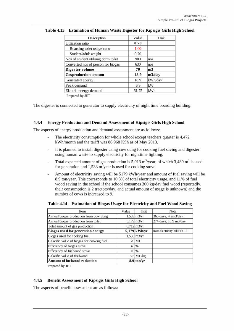
Table 4.13 Estimation of Human Waste Digester for Kipsigis Girls High School
Prepared by JET
The digester is connected to generator to supply electricity of night time boarding building.
4.4.4 Energy Production and Demand Assessment of Kipsigis Girls High School
The aspects of energy production and demand assessment are as follows:
- The electricity consumption for whole school except teachers quarter is 4,472 kWh/month and the tariff was 86,968 KSh as of May 2013.
- It is planned to install digester using cow dung for cooking fuel saving and digester using human waste to supply electricity for nighttime lighting.
- Total expected amount of gas production is 5,013 m3/year, of which 3,480 m3 is used for generation and 1,533 m3year is used for cooking stove.
- Amount of electricity saving will be 5179 kWh/year and amount of fuel saving will be 8.9 ton/year. This corresponds to 10.3% of total electricity usage, and 11% of fuel wood saving in the school if the school consumes 300 kg/day fuel wood (reportedly, their consumption is 2 tractors/day, and actual amount of usage is unknown) and the number of cows is increased to 9.
Table 4.14 Estimation of Biogas Usage for Electricity and Fuel Wood Saving
Prepared by JET
4.4.5 Benefit Assessment of Kipsigis Girls High School
The aspects of benefit assessment are as follows:
Description Value UnitUtilization ratio 0.70 Boarding toilet usage ratio 1.00 Student/adult weight 0.70Nos of student utilizing dorm toilet 900 nosConverted nos of person for biogas 630 nosDigester volume 70 m3Gasproduction amount 18.9 m3/dayGenerated energy 18.9 kWh/dayPeak demand 6.9 kWElectric energy demand 51.75 kWh
Item Value Unit NoteAnnual biogas production from cow dung 1,533 m3/yr 365 days, 4.2m3/dayAnnual biogas production from toilet 5,179 m3/yr 274 days, 18.9 m3/dayTotal amount of gas production 6,712 m3/yrBiogas used for generation energy 5,179 kWh/yr from electricity bill Feb-13
Biogas used for cooking fuel 1,533 m3/yrCalorific value of biogas for cooking fuel 20 MJEfficiency of biogas stove 45 %Efficiency of fuelwood stove 10 %Calorific value of fuelwood 15.5 MJ /kgAmount of fuelwood reduction 8.9 ton/yr

Attachment L-2 Simple Pre-F/S of Biogas Projects
-23-
- When unit cost of electricity is 19.5 KSh/kWh, the annual saving will be 100,983 KSh/year for electricity.
- When unit cost of fuel wood is 3,300 KSh/ton, annual saving for fuel wood will be 29,394 KSh.
- In total, the annual benefit of biogas system will be 130,357 KSh/year.
Table 4.15 Estimation of Benefit for Biogas System Installation
Prepared by JET
4.5 Mukumu Girls High School
4.5.1 Purpose of the Project and Justification of Selection of Mukumu Girls High School
The school is utilizing electricity for daily school demand and water pump. It consumes fuel wood and charcoal for energy demand. Biogas system is preferred to reduce electricity and fuel consumption.
4.5.2 Particular Features of the School of Mukumu Girls High School
The particular features other than above table are as follows.
- The school had the project to install water pump of 20 kW or 20 hp. Pump manager available for O&M of the biogas system.
- The school started fish pond and pig farming, and aims for self-supply of food.
- Discharge pipe line for bath room and toilet are same. It needs to obtain pipe line alignment sketch and need separation work. Outside pit latrine is used for daytime.
- Number of cow is currently 9. They are confined between 5:00-14:00, then allowed to graze in the afternoon. the current number is most likely to increase to 15.
4.5.3 Preliminary Design of Mukumu Girls High School
The demand for biogas is (i) cooking fuel, (ii) electricity for nighttime lighting in boarding building., and (iii) Water pump. The proposed system is as follows:
Item Value Unit NoteUnit cost of ton fuelwood 3300 KSh/ton Not known in this schoolUnit cost of unit electricity 19.5 KSh/kWh from electricity bill May-13
Benefit of saving electricity 100,983 KSh/yrBenefit of fuel wood saving 29,374 KSh/yrTotal benefit 130,357 KSh/yr
Attachment L-2 Simple Pre-F/S of Biogas Projects
-24-
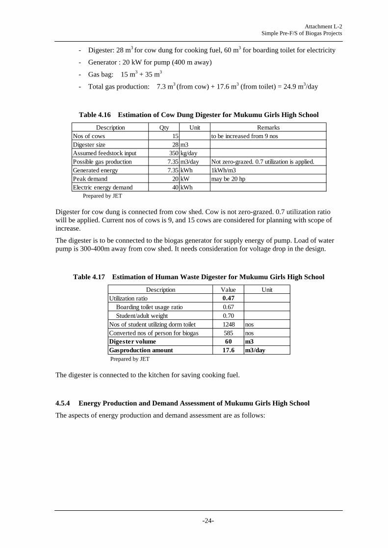
- Digester: 28 m3 for cow dung for cooking fuel, 60 m3 for boarding toilet for electricity
- Generator : 20 kW for pump (400 m away)
- Gas bag: 15 m3 + 35 m3
- Total gas production: 7.3 m3 (from cow) + 17.6 m3 (from toilet) = 24.9 m3/day
Table 4.16 Estimation of Cow Dung Digester for Mukumu Girls High School
Prepared by JET
Digester for cow dung is connected from cow shed. Cow is not zero-grazed. 0.7 utilization ratio will be applied. Current nos of cows is 9, and 15 cows are considered for planning with scope of increase.
The digester is to be connected to the biogas generator for supply energy of pump. Load of water pump is 300-400m away from cow shed. It needs consideration for voltage drop in the design.
Table 4.17 Estimation of Human Waste Digester for Mukumu Girls High School
Prepared by JET
The digester is connected to the kitchen for saving cooking fuel.
4.5.4 Energy Production and Demand Assessment of Mukumu Girls High School
The aspects of energy production and demand assessment are as follows:
Description Qty Unit RemarksNos of cows 15 to be increased from 9 nosDigester size 28 m3Assumed feedstock input 350 kg/dayPossible gas production 7.35 m3/day Not zero-grazed. 0.7 utilization is applied.Generated energy 7.35 kWh 1kWh/m3Peak demand 20 kW may be 20 hpElectric energy demand 40 kWh
Description Value UnitUtilization ratio 0.47 Boarding toilet usage ratio 0.67 Student/adult weight 0.70Nos of student utilizing dorm toilet 1248 nosConverted nos of person for biogas 585 nosDigester volume 60 m3Gasproduction amount 17.6 m3/day

Attachment L-2 Simple Pre-F/S of Biogas Projects
-25-
- The electricity consumption for whole school except teachers quarter is 2,791 kWh/month and the tariff was 49,983 KSh and for water pump was 2,954 kWh/month and 52,984 kSh as of May 2013.
- It is planned to install digester of cow dung for electricity supply for water pump and digester of toilet for cooking fuel supply. This is due to proximities to load centre.
- Total expected amount of gas production is 7,505 m3/year, of which 2,683 m3 is used for generation and 4,822 m3year is used for cooking stove.
- Amount of electricity saving will be 2,683 kWh/year and 28 ton/year fuel saving. This corresponds to 7.6% of pump electricity usage, and 35% of fuel wood.
Table 4.18 Estimation of Biogas Usage for Electricity and Fuel Wood Saving
Prepared by JET
4.5.5 Benefit Assessment
The aspects of energy production and demand assessment are as follows:
- When unit cost of electricity is 17.9 KSh/kWh, the annual saving will be 48,021 KSh/year for electricity.
- When unit cost of fuel wood is 4,500 KSh/ton, annual saving for fuel wood will be 126,005 KSh.
- In total, the annual benefit of biogas system will be 174,026 KSh/year.
- The fuel wood purchase in this school is high, as much as 4,500 KSh/ton. This corresponds to 26.1 KSh/m3 of the value of biogas, which is considered to be higher than electricity value. Accordingly, to use all biogas including from cow shed for fuelwood saving will increase the annual benefit. However, since cow shed is located very far a way from kitchen, it would be difficult unless another kitchen is build near cow shed.
Table 4.19 Estimation of Benefit for Biogas System Installation
Prepared by JET
Item Value Unit NoteAnnual biogas production from cow dung 2,683 m3/yr 365 days, 7.35m3/dayAnnual biogas production from toilet 4,822 m3/yr 274 days, 17.6 m3/dayTotal amount of gas production 7,505 m3/yrBiogas used for generation energy 2,683 kWh/yr from electricity bill Feb-13
Biogas used for cooking fuel 4,822 m3/yrCalorific value of biogas for cooking fuel 20 MJEfficiency of biogas stove 45 %Efficiency of fuelwood stove 10 %Calorific value of fuelwood 15.5 MJ /kgAmount of fuelwood reduction 28.0 ton/yr
Item Value Unit NoteUnit cost of ton fuelwood 4500 KSh/ton Tender resultUnit cost of unit electricity 17.9 KSh/kWh from electricity bill May-13
Benefit of saving electricity 48,021 KSh/yrBenefit of fuel wood saving 126,005 KSh/yrTotal benefit 174,026 KSh/yr

Attachment L-2 Simple Pre-F/S of Biogas Projects
-26-
4.6 Cardinal Otunga High School
4.6.1 Purpose of the Project and Justification of Selection of Cardinal Otunga High School
The school is conscious about environment protection. they have planted trees for fuel wood supply in 2012. However, the amount is not enough to continue and they need biogas system to reduce fuel wood consumption. They also consumes large amount of electricity for school activity and water pump. The consumption of diesel oil is high during power cut hours. The school is eager for project implementation with sufficient experience of construction supervision. The sense of ownership for the project is quite high.
4.6.2 Particular Features of the School of Cardinal Otunga High School
The particular features other than above table are as follows.
- In addition to cow dung, pig dung is also available.
- School farm where cow shed and pig shed are located is approximately 200m from load. this will require more consideration for gasline or cabling for powerline. Considering cost and pressure/voltage drop. Giving-up cow/pig dung might be suggested after the analysis.
- They have day time toilet and dormitory toilet. Dormitory toilet is under re-construction and it will be connected to septic tank by December 2013. Biogas digester can be connected to the new dormitory toilet.
- Toilet roof needs replacement every 7 months due to corrosion suspected to be hydrogen sulphide gas. Toilets are drained 6 times/year. at a cost of 15,000 kSh..
- Consumption of diesel oil is high to supply electricity during power-cut. Automatic change-over switch is installed. Every Tuesday, they experience a black out from 2-9 pm.
- They have just installed posho mill for school needs recently, this will increase electricity consumption. To supply the posho mill from biogas generator, confirmation of posho mill output will be necessary.
- Number of dormitory building is 14. Night time electricity for lighting of dormitory is also demand for biogas generation.
4.6.3 Preliminary Design of Cardinal Otunga High School
The demand for biogas is (i) cooking fuel, (ii) electricity for nighttime lighting in boarding building., and (iii) Water pump. The proposed system is as follows:
- Digester: 32 m3 for cow/pig dung for cooking fuel, 60 m3 for boarding toilet for
electricity
- Generator : 10 kW (for night time boarding)
- Gas bag: 25 m3 + 35 m3
- Total gas production: 12 m3 (from cow/pig) + 16.1 m3 (from toilet) = 28.1 m3/day

Attachment L-2 Simple Pre-F/S of Biogas Projects
-27-
Table 4.20 Estimation of Cow Dung Digester for Cardinal Otunga Girls High School
Prepared by JET
Digester for cow/pig dung is connected from cow shed and pig shed. It needs to construct long trench to collect cow/pig dung. Cows leave the cowshed between 14:00-16:00 daily. This therefore means that 0.7 utilization ratio is applied. Current nos of cows is 9, and 15 cows are considered for planning with scope of increase.
The digester is to be connected to the biogas generator for supply energy of pump. Load of water pump is 300-400m away from cow shed. It needs consideration for voltage drop in the design.
Table 4.21 Estimation of Human Waste Digester for Cardinal Otunga High School
Prepared by JET
The digester is connected to the kitchen for saving cooking fuel.
4.6.4 Energy Production and Demand Assessment of Cardinal Otunga High School
The aspects of energy production and demand assessment are as follows:
- The electricity consumption for whole school except teachers quarter is 1,519 kWh/month and the tariff was 30,212 KSh, and for water pump was 598 kWh/month and 11,746 kSh as of May 2013.
- It is planned to install digester of cow dung for night time electricity supply for boarding school and digester of toilet for cooking fuel supply.
- Total expected amount of gas production is 8,791 m3/year, of which 4,380 m3 is used for generation and 4,411 m3year is used for cooking stove.
- Amount of electricity saving will be 4,380 kWh/year and amount of fuel saving will be 25.6 ton/year. This corresponds to 17% of total electricity usage, and 8.5% of fuel wood (if cost is 3300 KSh/ton and they spend 1 million KSh/year for fuel wood).
Description Qty Unit Remarks
Nos of cows 178 cows to be increased to 10 cows.50pigs counted (7 pigs=1 cow)
Digester size 32 m3Assumed feedstock input 400 kg/dayPossible gas production 12 m3/day Not zero-grazed. 0.9 utilization ratio is applied
Generated energy 12 kWh 1kWh/m3
Peak demand 15 kWNeed to adjust according to posho mill hpFor dormitory, 14building x535W=7.5 kW
Electric energy demand 67.5 kWh
Description Value UnitUtilization ratio 0.54 Boarding toilet usage ratio 0.67 Student/adult weight 0.80Nos of student utilizing dorm toilet 1000 nosConverted nos of person for biogas 536 nosDigester volume 60 m3Gasproduction amount 16.1 m3/day

Attachment L-2 Simple Pre-F/S of Biogas Projects
-28-
Table 4.22 Estimation of Biogas Usage for Electricity and Fuel Wood Saving
Prepared by JET
4.6.5 Benefit Assessment of Cardinal Otunga High School
The aspects of benefit assessment are as follows:
- When unit cost of electricity is 17.9 KSh/kWh, the annual saving will be 48,021 KSh/year for electricity.
- When unit cost of fuel wood is 4,500 KSh/ton, annual saving for fuel wood will be 126,005 KSh.
- In total, the annual benefit of biogas system will be 174,026 KSh/year.
- The fuelwood purchase in this school is high, as much as 4,500 KSh/ton. This corresponds to 26.1 KSh/m3 of the value of biogas, which is considered to be higher than electricity value. Accordingly, to use all biogas including from cow shed for fuel wood saving will increase the annual benefit. However, since cowshed is located very far a way from kitchen, it would be difficult unless another kitchen is build near cow shed.
Table 4.23 Estimation of Benefit for Biogas System Installation
Prepared by JET
Item Value Unit NoteAnnual biogas production from cow dung 4,380 m3/yr 365 days, 12m3/dayAnnual biogas production from human waste 4,411 m3/yr 274 days, 16.1 m3/dayTotal amount of gas production 8,791 m3/yrBiogas used for generation energy 4,380 kWh/yr from electricity bill Feb-13
Biogas used for cooking fuel 4,411 m3/yrCalorific value of biogas for cooking fuel 20 MJ/m3Efficiency of biogas stove 45 %Efficiency of fuelwood stove 10 %Calorific value of fuelwood 15.5 MJ /kgAmount of fuelwood reduction 25.6 ton/yr
Item Value Unit NoteUnit cost of ton fuelwood 3300 KSh/ton Not known in this schoolUnit cost of unit electricity 19.9 KSh/kWh from electricity bill Apr-13
Benefit of saving electricity 87,162 KSh/yrBenefit of fuel wood saving 84,528 KSh/yrTotal benefit 171,690 KSh/yr

Attachment L-2 Simple Pre-F/S of Biogas Projects
-29-
Table 4.24 Estimation of Biogas Usage for Electricity and Fuel Wood Saving
Prepared by JET
4.6.6 Benefit Assessment of Cardinal Otunga High School
The aspects of benefit assessment are as follows:
- When unit cost of electricity is 17.9 KSh/kWh, the annual saving will be 48,021 KSh/year for electricity.
- When unit cost of fuel wood is 4,500 KSh/ton, annual saving for fuel wood will be 126,005 KSh.
- In total, the annual benefit of biogas system will be 174,026 KSh/year.
- The fuel wood purchase in this school is high, as much as 4,500 KSh/ton. This corresponds to 26.1 KSh/m3 of the value of biogas, which is considered to be higher than electricity value. Accordingly, to use all biogas including from cow shed for fuelwood saving will increase the annual benefit. However, since cow shed is located very far a way from kitchen, it would be difficult unless another kitchen is build near cow shed.
Table 4.25 Estimation of Benefit for Biogas System Installation
Prepared by JET
CHAPTER 5 COST ESTIMATION AND ECONOMIC/FINANCIAL EVALUATION FOR SIX BIOGAS PROJECTS
5.1 Cost Estimation
Site survey for six candidate biogas projects in high schools in Kenya was conducted in May to June 2013. The surveyed schools are namely: Nyeri High School, Rware High School, Litein High School, Kipsigis Girls High School, Mukumu Girls High School, and Cardinal Otunga High
Item Value Unit NoteAnnual biogas production from cow dung 2,683 m3/yr 365 days, 7.35m3/dayAnnual biogas production from toilet 4,822 m3/yr 274 days, 17.6 m3/dayTotal amount of gas production 7,505 m3/yrBiogas used for generation energy 2,683 kWh/yr from electricity bill Feb-13
Biogas used for cooking fuel 4,822 m3/yrCalorific value of biogas for cooking fuel 20 MJEfficiency of biogas stove 45 %Efficiency of fuelwood stove 10 %Calorific value of fuelwood 15.5 MJ /kgAmount of fuelwood reduction 28.0 ton/yr
Item Value Unit NoteUnit cost of ton fuelwood 4500 KSh/ton Tender resultUnit cost of unit electricity 17.9 KSh/kWh from electricity bill May-13
Benefit of saving electricity 48,021 KSh/yrBenefit of fuel wood saving 126,005 KSh/yrTotal benefit 174,026 KSh/yr

Attachment L-2 Simple Pre-F/S of Biogas Projects
-30-
School. “Site Survey Memo of Biogas : 1 Nyeri High School and Rware High School” and “Site Survey Memo of Biogas 2: Rift Valle, Western, and Nyanza Sites” reported the result of the survey with the outline, particular features, basic design, demand assessment, and benefit assessment for six schools. This paper is prepared for cost estimation and economic/financial evaluation for six schools.
Past REA projects at Mangu High School and Moi Girl’s School were referred for the base cost for biogas system component. The reference price is summarized in the table below.
Table 5.1 Reference Values for the Cost Estimation
Prepared by JET
The cost estimation is conducted for the purpose of preliminary financial and economic evaluation to assess the project feasibility. The estimation is based on rough assumption of quantity especially in civil works. The quantity of excavation, cement, concrete works, buildings, etc, needs to be determined with more detailed layout and design in the next stage.
For the estimation of respective quantity and specification, following formulas were applied.
1) Biogas digester: y = 2,617 x + 256,700, ,where y: cost (KSh), x: digester volume (m3)
2) Excavation works: 2,052 KSh/m3 3) Biogas bag: 20,550 KSh/m3
4) Biogas generator: y=20,000x +100,000
Qty Unit Unit cost Amount Qty Unit Unit cost Amount0 Sanitation, protection, removal works 1 lot 35,000 35,000 1 lot 35,000 35,0001-A Excavation 1 item 376,500 376,500 1 item 375,500 375,500
Trench toilet 16 cubicles 1 lot 631,000 631,0002-A Dome digestor 100m3 2 nos 518,350 1,036,700 2 nos 495,750 991,500
Dome digester 50m3 1 nos 387,500 387,500 03-A Gas holding steel tank 3 nos 45,700 137,100 2 nos 45,750 91,5003-B Gas outlet connection 50mm valve 3 nos 4,700 14,100 2 nos 4,500 9,0003-C Biogas flow meters 2 nos 36,500 73,000 2 nos 36,500 73,0004-A 20m3 PVC gas bag 1 nos 411,000 411,000 1 nos 411,000 411,0005-A Biogas generator 20kVA 1 nos 495,500 495,500 1 nos 454,000 454,0005-B Energy meters 1 nos 50,000 50,000 1 nos 50,000 50,0005-C 3-P Distribution board 1 nos 59,500 59,500 1 nos 59,000 59,0005-D Switchgear and safety control 1 nos 91,000 91,000 1 nos 91,000 91,0005-E Solenoid valves to switch off gas 1 nos 45,500 45,500 1 nos 45,500 45,5005-F Biogas purification unit 1 nos 61,000 61,0005-G 15hp 12kW existing pump cable work 1 nos 183,000 183,0006-A Plumbing works 50mm dia pipe to gas ba 1 nos 256,000 256,0007-A Chain link fence 1 nos 91,000 91,000
8-ASafey, fire extinguisher, alarm, somokedetector,signs
1 nos 27,000 27,000
9-A System design 1 Lot 246,000 246,00010-A Testing and commission for 2 eeks 1 Lot 62,000 62,00011-A Technical backstopping in O&M 1 Lot 164,500 164,50011-B Data collection 1 Lot 18,500 18,50011-C Training, manual 1 Lot 73,000 73,00011-D Drawing and video 1 Lot 255,500 255,50011-E 6month operation data 1 Lot 45,500 45,500
Subtotal 4,695,400VAT 16% 751,264TOTAL 5,446,664
Moi GirlsMangu HSItemSN

Attachment L-2 Simple Pre-F/S of Biogas Projects
-31-
, where y: cost (KSh), x: capacity of engibne-generator (kVA) The base cost in table 1 was the value in 2010. Accordingly, inflation rate (4.91%, Kenyan Bureau of Statistics) was applied and price in 2013 was calculated as compounded interest.
For other items, base cost is applied in proportion to the estimated quantity.
The result of cost estimation and recovery year is shown in the table below.
Table 5.2 Result of the Cost Estimation
Prepared by JET Litein high school requires long distance excavation of piping work and additional toilet with septic tank. Because of this, the project cost becomes much higher than other projects (6.86 million KSh) .
Meanwhile, Rware high school does not have much demand for electricity since the school is day school and water supply is depending on municipal water. Accordingly, no electric supply system is planned in the school, which makes project cost smaller than other sites(1.68 million Ksh).
5.2 Financial Evaluation
Financial benefit for biogas system consists of following items:
- Saving of electricity tariff:
- Saving of fuel wood purchase
The electricity tariff rate was set based on actual payment of electricity bill, i.e., amount of the tariff payment in KSh (including fuel surcharge and other adjustment) of the month divided by the amount of electric energy in kWh consumed in the month. The tariff rate is ranged from 17.9 to 19.9KSh/kWh, expect for 8.7 KSh/kWh for Rware High School. The tariff of Rware is low since the consumption of the school is quite small, about 1000 kWh per month.
As for fuel wood price, many of the price per ton that was paid actually by the school was not clear. Accordingly, 3,300 KSh/ton, general price in Nyeri, was applied for all school for the comparison.
Item
Qty unit KSh Qty unit KSh Qty unit KSh Qty unit KSh Qty unit KSh Qty unit KShBiogas Digester for Toilet 60 m3 413,720 60 m3 413,720 50 m3 387,550 60 m3 413,720 60 m3 413,720Biogas Digeter for Cow Shed 32 m3 340,444 24 m3 319,508 32 m3 340,444 16 m3 298,572 28 m3 329,976 32 m3 340,444Excavation and civil works 1 lot 188,830 1 lot 49,260 1 lot 804,430 1 lot 135,465 1 lot 180,620 1 lot 188,830Additional toilet facility with septic tank 1 lot 631,000Gas holding steel tank and connection valve 2 nos 100,800 1 nos 50,400 2 nos 100,800 2 nos 100,800 2 nos 100,800 2 nos 100,800Bigoas flow meter 2 nos 73,000 1 nos 36,500 2 nos 73,000 2 nos 73,000 2 nos 73,000 2 nos 73,000PVC gas bag 1 nos 411,000 1 nos 411,000 2 nos 822,000 2 nos 513,750 2 nos 616,500 2 nos 616,500Biogas generator 7 kVA 240,000 20 kVA 500,000 10 kVA 300,000 20 kVA 500,000 20 kVA 500,000Energy meter 1 nos 50,000 1 nos 50,000 1 nos 50,000 1 nos 50,000 1 nos 50,000Distribution board, switch gear 1 nos 150,500 1 nos 150,500 1 nos 150,500 1 nos 150,500 1 nos 150,500Biogas filter and solenoid valve 1 nos 106,500 1 nos 106,500 1 nos 106,500 1 nos 106,500 1 nos 106,500Cable work 1 lot 200,000 1 lot 600,000 1 lot 175,000 1 lot 200,000 1 lot 300,000Pipe work 1 lot 250,000 1 lot 150,000 1 lot 500,000 1 lot 150,000 1 lot 250,000 1 lot 250,000Fence and safety arrangement 1 lot 118,000 1 lot 70,800 1 lot 118,000 1 lot 118,000 1 lot 118,000 1 lot 118,000Subtotal 2,642,794 1,087,468 5,210,394 2,559,137 3,089,616 3,208,294
Detailed design and drawing 1 lot 246,000 1 lot 147,600 1 lot 369,000 1 lot 246,000 1 lot 246,000 1 lot 501,500Testing, commissioning, training 1 lot 363,500 1 lot 218,100 1 lot 363,500 1 lot 363,500 1 lot 363,500 1 lot 363,500
Total Cost 3,252,294 1,453,168 5,942,894 3,168,637 3,699,116 4,073,294Total Cost adjusted with Inflation 2010/13 4.91%/yKsh 3,755,264 4.91%/yr 1,677,902 4.91%/yr 6,861,967 4.91%/yr 3,658,669 4.91%/yr 4,271,187 4.91%/yr 4,703,232
Annual financial benefit Ksh 180,050 62,945 164,856 130,357 174,026 171,690Recovery year yr 21 yr 27 yr 42 yr 28 yr 25 yr 27
Remarks
Nyeri High School Rware High School Litein High School Kipsigis Girls HighSchool
Mukumu Girls HighSchool
Cardinal Otunga HighSchool
Cable line length 200mGas bag: 10m3 + 20 m3Gas bag: 10m3 + 20 m3Gas bag: 5m3 + 20 m3
300m pipe work & cow shedtrench, Pump 700m away

Attachment L-2 Simple Pre-F/S of Biogas Projects
-32-
The outline of the cost estimation and recovery year (project cost/annual financial benefit) is shown in the table below.
Table 5.3 Summary for Financial Evaluation
Prepared by JET The recovery year ranges from 21 years to 42 years. Since the project life is expected approx. 30 years, Litein High School which requires 42 years for recovery, is not considered to be feasible. For other schools, recovery year is ranged from 23 to 28 years, which can be financially justified.
FIRR will be negative for all six projects, and cannot be calculated.
5.3 Economic Evaluation
For counting economic benefit, it is necessary to quantify indirect value of socioeconomic and environmental benefit. Following table explains the contents of economic benefit which will be borne from the biogas system.
Table 5.4 Economic Benefit
SN Type of Economic Benefit Explanation 1
Benefit as electricity saving from diesel oil
When electricity is generated using biogas, the electric energy can be considered to save electricity from diesel generation system in grid, since the cost of diesel generation is higher than that of hydropower. The cost of electricity from diesel generation can be considered as economic benefit, in place of grid electricity tariff.
2 Benefit of carbon reduction by biogas generation
CO2 emission reduction is expected from biogas generation since it replaces energy from diesel generation. Emission factor of diesel oil can be applied to count economic benefit.
3 Benefit from fuelwood saving
The benefit is the same as financial benefit of fuelwood saving.
4 Fuelwoood carbon absorption benefit
The saved fuel wood by biogas system is considered to absorb CO2 in forest. The carbon credit with the absorption of CO2 amount is considered to be economic benefit.
5 Fuelwood carbon off-set benefit
As well as electricity, saved amount of fuelwood is considered to replace coal, and corresponding amount of CO2 from the replaced coal is considered to be economic benefit of carbon reduction.
6 Fuel wood economic value to prevent deforestation
Saving of losses in economic sectors resulting from deforestation is counted as economic benefit. The components of this economic value are: growing of crops and horticulture, fishing, water supply, public administration and defense,
Item Unit Nyeri HighSchool
Rware HighSchool
Litein HighSchool
KipsigisGirls High
School
MukumuGirls High
School
CardinalOtunga
High SchoolProject Cost KSh 3,755,264 1,453,168 6,861,967 3,658,669 4,271,187 4,703,232Electricity tariff rate KSh/kWh 19.7 8.7 18.1 19.5 17.9 19.9Annual planned generated energy kWh/yr 2,321 4,380 5,179 2,683 4,380Annual planned fuelwood Saving ton/yr 36.3 19.1 25.9 8.9 28.0 25.6Financial benefit KSh/yr 165,466 62,945 164,856 130,357 174,026 171,690Recovery year yr 23 23 42 28 25 27

Attachment L-2 Simple Pre-F/S of Biogas Projects
-33-
deforestation effects on carbon sequestration, and deforestation effects on health (malaria). “The Role and Contribution of Montane Forests and Related Ecosystem Services to the Kenyan Economy” of UNEP quantified the economic value as much as 921,165 KSh/ha.
Prepared by JET To quantify the above economic value, following parameters and formulas were used.
Base condition:
Diesel Oil Price 110.00 KSh/L Diesel efficiency 2.40 kWh/L Emission factor of electricity 0.81805 ton-CO2/MWh Price of fuel wood 3,300 KSh/ton Exchange rate 86.28 KSh/US$ Carbon credit 1,294 KSh/ton-CO2
Source: The Role and Contribution of Montane Forests and Related Ecosystem Services to the Kenyan Economy”, 2012, UNEP
Fuelw1od carbon absorption :
Carbon Absorption A = W x E x (1+R) x C% ton-CO2 reduction = A x 44/12 Where, W Weight of saved tree, ton E Coefficient for tree and branch addition: 1.52 R Ratio of ground/underground portion: 0.26 C% Carbon component percentage: 0.5
Source: Forestry and Forest Products Research Institute, Japan
Fuelwood carbon off-set:
ton-CO2 reduction = W x (1-M/100) x H x EF x BE Where, W Weight of saved tree, ton M Moisture content, %: 10 H Calorific value GJ/ton: 15.5 EF Emission coefficient of coal, ton-CO2/GJ: 0.09 BE Boiler efficiency ratio (fuel wood/fossil fuel): 1 Source: Forestry and Forest Products Research Institute, Japan Fuelwood economic value to prevent deforestation
Amount of carbon storage 190 C-ton/ha Weight of wood body 198.4 ton/ha Economic value per area 921,165 KSh/ha Economic value per ton fuel wood 4,643 KSh/ton Source: The Role and Contribution of Montane Forests and Related Ecosystem Services to the Kenyan Economy”, 2012, UNEP
According to the above assumption, each economic value was calculated. With the total economic benefit, EIRR for each project was worked out. Generally, EIRR more than 10% is justified in public project.

Attachment L-2 Simple Pre-F/S of Biogas Projects
-34-
Since the economic benefit of fuelwood saving is high, Rware high school, which utilize all biogas for fuelwood saving and no electric generation system will be installed, shows highest EIRR value, 16.4%. Meanwhile, Litein High school, of which cost was highest, shows EIRR of 5.85 %
As for Kipsigis Girls High School, the EIRR was only 7.8% which may be considered not being feasible. However, if the school applies all the biogas to replace fuel wood, the EIRR will be increased to be 13.5%. The project will be economically justified depending on the usage of the gas.
Table 5.5 Summary of Economic Evaluation
Prepared by JET
CHAPTER 6 OPTION STUDY FOR NYERI HS
6.1 Background
Biogas produced in anaerobic digester can be applied both production of the electricity using engine-generator and cooking fuel for the replacement of fuelwood. Since production of electricity requires installation of high cost generator and larger maintenance cost, it is considered that application of biogas only to cooking fuel would be more economically feasible, as long as demand for fuelwood is high. Accordingly, for the Nyeri High School (HS) biogas system plan of which is ranked first among six sites, the economic feasibility is assessed and compared between the cases (i) biogas supply for both electricity and cooking fuel and (ii) biogas supply for cooking fuel only.
6.2 Cost Estimation
In the original plan with generator of Nyeri HS project, the system will supply electric power for lighting, which use about 1/3 of total produced biogas, and will supply remaining 2/3 of produced biogas for cooking fuel. For the optional system without generator, the system will supply all biogas for cooking fuel.
The cost is assessed with the simple assumption from past tender document of Mangu biogas system conducted in 2010 with applying inflation rate. The cost for system with generator was estimated to be about 3.8 million KSh, while that of without generator was about 2.8 million KSh
Item Unit Nyeri HighSchool
Rware HighSchool
Litein HighSchool
KipsigisGirls High
School
MukumuGirls High
School
CardinalOtunga
High SchoolBenefit as diesel generation saving KSh/yr 106,356 0 200,750 237,353 122,959 200,750Benefit of electricity carbon reduction KSh/yr 2,457 0 4,637 5,483 2,840 4,637Benefit from fuelwood saving KSh/yr 119,717 62,945 85,578 29,374 126,005 84,528Fuelwoood carbon absorption benefit KSh/yr 164,854 86,677 117,844 40,449 127,242 116,398Fuel wood carbon off-set benefit KSh/yr 58,947 30,993 42,137 14,463 45,498 41,620Fuel wood economic value KSh/yr 168,427 88,555 120,397 41,326 130,000 118,920Total economic benefit KSh/yr 620,758 269,170 571,344 368,448 554,544 566,853EIRR 15.09% 16.44% 5.85% 7.79% 11.27% 10.26%

Attachment L-2 Simple Pre-F/S of Biogas Projects
-35-
Table 6.1 Cost Estimation of Nyeri HS with/Without Generator
Prepared by JET
6.3 Demand in Nyeri HS
The electricity consumption of Nyeri HS is reported to be about 5,000 kWh/month, about 60,000 kWh/year. The annual fuelwood consumption is about 300 ton/year in Nyeri School. This amount of fuelwood consumption is much higher even if all biogas is used for cooking fuel replacing with fuel wood (49.8 ton/year). If all feedstock is used for reduction of fuelwood, 1/6 of current use will be saved.
6.4 Financial and Economic Benefit
The annual financial benefit is calculated from (i) the amount of electricity tariff saving and (ii) fuel wood saving in the original plan with generator. For alternative plan without generator, only fuel wood saving is counted for financial benefit. The annual economic benefit for generation is calculated from saving of diesel oil assuming that electricity generated from biogas replaces diesel generation in grid. CO2 emission reduction benefit is also counted. The economic benefit for fuel wood reduction is calculated from fuel wood saving, fuelwood carbon absorption benefit, fuelwood carbon off-set benefit, and fuelwood economic value from forest preservation.
For detailed methodology of calculating economic benefit, see the Progress Report 3 for Project for Establishment of Rural Electrification Model Using Renewable Energy. The result is shown in the table below.
Item
Qty unit KSh Qty unit KShBiogas Digester for Toilet 60 m3 413,720 60 m3 413,720Biogas Digeter for Cow Shed 32 m3 340,444 32 m3 340,444Excavation and civil works 1 lot 188,830 1 lot 188,830Additional toilet facility with septic tankGas holding steel tank and connection valve 2 nos 100,800 2 nos 100,800Bigoas flow meter 2 nos 73,000 2 nos 73,000PVC gas bag 1 nos 411,000 1 nos 411,000Biogas generator 7 kVA 240,000 kVAEnergy meter 1 nos 50,000 nosDistribution board, switch gear 1 nos 150,500 nosBiogas filter and solenoid valve 1 nos 106,500 1 nos 106,500Cable work 1 lot 200,000 lotPipe work 1 lot 250,000 1 lot 250,000Fence and safety arrangement 1 lot 118,000 1 lot 118,000Subtotal 2,642,794 2,002,294
Detailed design and drawing 1 lot 246,000 1 lot 186,380Testing, commissioning, training 1 lot 363,500 1 lot 275,403
Total Cost 3,252,294 2,464,077Total Cost adjusted with Inflation 2010/13 4.91%/yKsh 3,755,264 4.91%/yKsh 2,845,149
Nyeri High Schoolwithout generator
Nyeri High Schoolwith Generator

Attachment L-2 Simple Pre-F/S of Biogas Projects
-36-
Table 6.2 Financial and Economic Evaluation with/without Generator
Prepared by JET As the result, the financial benefit for system with generator was 165,466 Ksh/yr, higher than without generator (cooking fuel supply only), 164,181 Ksh/yr. However, since investment cost with generator was much higher, recovery year of the system without generator has advantage, 17 years, while that of the system with generator was 23 years.
Meanwhile, economic benefit will be larger in the system without generator (702,086 KSh/yr) than system with generator (620,758 KSh/yr), since economic benefit of forest protection (fuelwood economic value) is considered to be large. The EIRR for the system with generator was 15.1%, while that of without generator was 24.2%.
6.5 Conclusion
The financial return for electricity and cooking fuel from the same amount gas is almost the same at the present electricity tariff rate and fuelwood price. The financial value of unit biogas for fuelwood replacement and electricity generation for the case of Nyeri HS is shown in the table below.
Table 6.3 Value of Biogas for Fuel wood and Electricity Replacement
Fuelwood replacement Electricity supply 19.2 KSh/m3 19.7 KSh/m3
(Condition: 19.7 KSh/kWh for grid electricity, 3,300 KSh/ton for fuelwood purchase) Prepared by JET
Base condition:Diesel Oil Price 110.00 KSh/LDiesel efficiency 2.40 kWh/LEmission factor of electricity 0.81805 ton-CO2/MWhPrice of fuel wood 3,300 KSh/tonExchange rate 86.28 KSh/US$Carbon credit 1,294 KSh/ton-CO2 (15US$/ton)
Item Unit Nyeri High Schoolwith generator
Nyeri High Schoolwithout generator
Project Cost KSh 3,755,264 2,845,149Planned gas production for fuelwood saving m3/yr 6,248 8,568Planned gas production for electricity saving m3/yr 2,321 0Electricity tariff rate KSh/kWh 19.7 19.7Annual planned generated energy kWh/yr 2,321 0Annual planned fuelwood Saving ton/yr 36.3 49.8Financial benefit KSh/yr 165,466 164,181Recovery year yr 23 17
Benefit of diesel generation saving KSh/yr 106,356 0Benefit of CO2 emission reduction bybiogas generation
KSh/yr 2,457 0
Benefit from fuelwood saving KSh/yr 119,717 164,181Fuelwood carbon absorption benefit KSh/yr 164,854 226,082Fuel wood carbon off-set benefit KSh/yr 58,947 80,840Fuel wood economic value KSh/yr 168,427 230,982Total economic benefit KSh/yr 620,758 702,085EIRR 15.09% 24.18%Shadow exchange rate is not considered in financial cost.

Attachment L-2 Simple Pre-F/S of Biogas Projects
-37-
Meanwhile, initial cost of biogas system with generator is 32% higher compared with biogas system for cooking fuel supply only. In addition, generator requires overhaul every 5-7 years and the maintenance cost is also much higher than that of system without generator.
The annual fuelwood requirement in the school (about 300 ton/yr) is larger than the amount possibly replaced by biogas (about 50 ton/yr), it is more financially feasible to utilize all biogas for fuelwood replacement than to supply biogas for electricity generation.
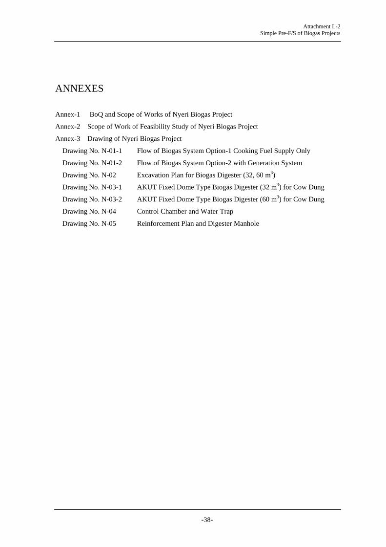
Attachment L-2 Simple Pre-F/S of Biogas Projects
-38-
ANNEXES
Annex-1 BoQ and Scope of Works of Nyeri Biogas Project
Annex-2 Scope of Work of Feasibility Study of Nyeri Biogas Project
Annex-3 Drawing of Nyeri Biogas Project
Drawing No. N-01-1 Flow of Biogas System Option-1 Cooking Fuel Supply Only
Drawing No. N-01-2 Flow of Biogas System Option-2 with Generation System
Drawing No. N-02 Excavation Plan for Biogas Digester (32, 60 m3)
Drawing No. N-03-1 AKUT Fixed Dome Type Biogas Digester (32 m3) for Cow Dung
Drawing No. N-03-2 AKUT Fixed Dome Type Biogas Digester (60 m3) for Cow Dung
Drawing No. N-04 Control Chamber and Water Trap
Drawing No. N-05 Reinforcement Plan and Digester Manhole

Attachment L-2 Simple Pre-F/S of Biogas Projects
-39-
Annex-1 BoQ and Scope of Works of Nyeri Biogas Project
*Following BoQ was prepared in the stage of Pre-Feasibility Study. The quantity, details and specifications need to be reviewed and revised during Feasibility Study Stage.
Option-1 Cooking Fuel Supply System (without generator) SN Item Quantity Unit Details and Specification
A. Civil, Construction and Installation Works A-1 Excavation works and
backfilling 1 set Site cleaning and excavation shall be conducted for
biogas digester, trenches, ditches, chambers, pipeline routes, and foundation of gas bag house shall be conducted. Landscaping after backfilling shall be conducted. Water shall be drained or pumped up.
A-2 32m3 cow dung biogas digester and related works
1 Set 32 m3 AKUT type fixed dome digester shall be constructed with manhole, feeding chamber, PVC pipe connection, expansion chamber, reinforced concrete beam and slab, and gas outlet, connected from cow shed and to garden. [Drawing No.: N-02, N03-1, N-05]
A-3 60 m3 human waster biogas digester and related works
1 Set 60 m3 AKUT type fixed dome digester shall be constructed with manhole, feeding chamber, PVC pipe connection, expansion chamber, reinforced concrete beam and slab, and gas outlet., connected from the pipe of sewer line from toilet and to sewer line to septic tank. [Drawing No.: N-02, N03-1, N-05]
A-4 Two cow sheds modification
40* m2 Modification work of cow shed with floor gravel laying and concrete placement to facilitate cow dung gathering shall be conducted for two nos of cow sheds.
A-5 Trench work (from cow shed to digester, from digester to garden)
100* m Stone masonry trench shall be constructed for: (i) from the cow shed to the feeding chamber of the digester and (ii) from the expansion chamber to the garden. The trench shall not be smaller than W300xH400*
A-6 Piping work for human waste digester
10** m Pipe connection work for slurry shall be done from the existing toilet sewer line to the human waste digester with manholes at the jointing part and joints and valves in the pipe line.
A-7 Gas pipeline from cow dung digester to the kitchen
200 m Gas pipe line with Φ32 mm PPP gas pipe, with 1-2% slope, shall be installed from cow dung digester to the kitchen. Chambers for water traps shall be constructed and water traps shall be installed very minimum 50 m or any folding point of the gas pipeline. A control chamber with a gas sampling nipple and a manometer shall be installed. [Drawing No.: N-04]
A-8 Gas pipeline from human waste digester to the kitchen
200 m Gas pipe line of Φ32 mm PPP gas pipe, 1-2% slope, from human waste digester to the kitchen shall in installed. Water traps and water trap chambers every minimum 50 m shall be installed. [Drawing No.: N-04]
A-9 Control Chamber 2 Sets Control chambers shall be constructed and a gas sampling nipple and a manometer shall be installed in the Control Chamber. One Control Chamber shall be installed in the gas pipe line of human digester and one control chamber in the gas pipe line of cow dung digester.
A-10 Gas holder bag 1 Sets Minimum 40 m3 gas bag made of Polyvinyl chloride (PVC) or Isobutylene Isoprene Rubber (IIR) shall be installed and connected from the gas pipe line. The gas bag shall be connected to the kitchen cooking stoves. Leakage test shall be conducted. The material of gas bag

Attachment L-2 Simple Pre-F/S of Biogas Projects
-40-
SN Item Quantity Unit Details and Specification shall be resistant to acid and alkali corrosion, resistance to wear and friction. Life span shall be more than 10 years. Suitable temperature at 0-50 oC.
A-111
Biogas flow meter 3 Sets The gas flow meter recording in m3 with one decimal place shall be installed one for the outlet of cow dung digester, one for the outlet of human waste digester, and one for the gas bag. Nominal flow rate shall be up to 2.0 m3/h. Maximum working pressure shall be more than 10 kPa. Pressure loss shall be ≤200Pa.Air tightness shall have no leakage under 10 kPa. In addition, 3 sets of the same flow meter shall be supplied for the replacement purpose.
A-12 Biogas filtering unit 2 Sets Activated carbon filter units to remove hydrogen sulfide, more than 99% purifying efficiency shall be installed for the cow dung digester and human waste digester. The unit container material shall be durable for H2S corrosion.
A-13 Manometer 3 Sets Manometers of highly resistant to corrosion shall be supplied and installed, one in the control chamber of cow dung digester, one in the control chamber of human waste digester, and one in the kitchen.
A-14 Gas Valve 1 Set Gas valve shall be installed to stop gas flow from the gas bag.
A-15 Gas holder house 40 x 1 m2 Stone masonry and zing roof gas holder house shall be constructed. The house shall have ventilation and warning sign of leakage. Door shall be rocked.
A-16 Biogas stove 4 Nos Biogas stove with double burner, with automatic starter switches and 2 meters of hosepipe. Each burner shall have heat load more than 2.5 kW, gas consumption rate 0.4-0.6 m3/h, and efficiency more than 57%.
B. Miscellaneous Works B-1 Safety arrangement 1 Set Warning signs at each digester location, fire distinguisher
at kitchen, fire alarm at kitchen shall be supplied and installed.
B-2 Sign board 1 Set Sign boards indicating facility and equipment type shall be installed at digester locations and kitchen.
C. Related Works C-1 Testing and
commissioning 1 Set Commissioning shall be done after the observation of gas
production. Gas stove test shall be conducted in the commissioning with confirmation of gas pressure and output. Testing record for gas production amount shall be recorded and submitted for initial 2 months after commissioning. Testing format shall be submitted and operation test shall be conducted for initial six months after commissioning. Biogas analysis using gas chromatography shall be conducted and analysis result of percentage CH4, N2, CO2, H2, H2S, and O2 shall be reported.
C-2 Documentation 1 Set Following documents shall be prepared and submitted 3 copies to the Client and 1 copy to the User. Work Plan including, Detailed work schedule,
Contractor’s organization chart and personnel list, Consolidated drawings of layout of digester, pipe layout, toilet, and other related facility, Bill of quantity, and safety plan
Drawings for approval and drawings for work of detailed drawings of digester, gas pipe, slurry pipes,

Attachment L-2 Simple Pre-F/S of Biogas Projects
-41-
SN Item Quantity Unit Details and Specification ditches, houses, and other related facilities that the Contractor will install and/or construct
As built drawings Format for testing and commissioning Record of monitoring (record of input, operation
record, gas production, energy generation) Program of user training User Manual Record of user training and user’s understanding List of consumables and spare parts and supplier’s
contact list Bills of Quantity and Cost
C-3 User training 1 Set User training with training program and shall be conducted at least four persons (operators and supervisor) assigned from the user. User manual shall be provided to the Client and the User.
C-4 Technical support 1 Set Technical supports shall be provided for initial one year for operation and maintenance of the user from the date of commissioning.
C-5 Supply of maintenance tools and spare parts
1 Set The maintenance tools necessary for operation and maintenance and spare parts including filtering materials shall be provided for 3 years operation.
C-6 Transportation 1 Set The transportation shall cover all supply of materials and equipment.
C-7 Labor 1 Set The labor shall cover all construction, civil , electrical, installation works.
C-8 Administration 1 Set Administration shall cover all administration works including communications and documentations.
*The quantity and size is rough estimate in Pre-FS. Those shall be reviewed and revised according to the result of feasibility study. **If toilet sewer line is the same as waste water from shower room, additional independent sewer line exclusive for toilet shall be constructed.

Attachment L-2 Simple Pre-F/S of Biogas Projects
-42-
Above is a rough layout. Detailed survey drawing with 1/1000 or 1/2000 scale shall be prepared and plan for facilities such as digester, gas bag, power house shall be arranged in the feasibility study
Figure A Sketch Layout of Nyeri Biogas System
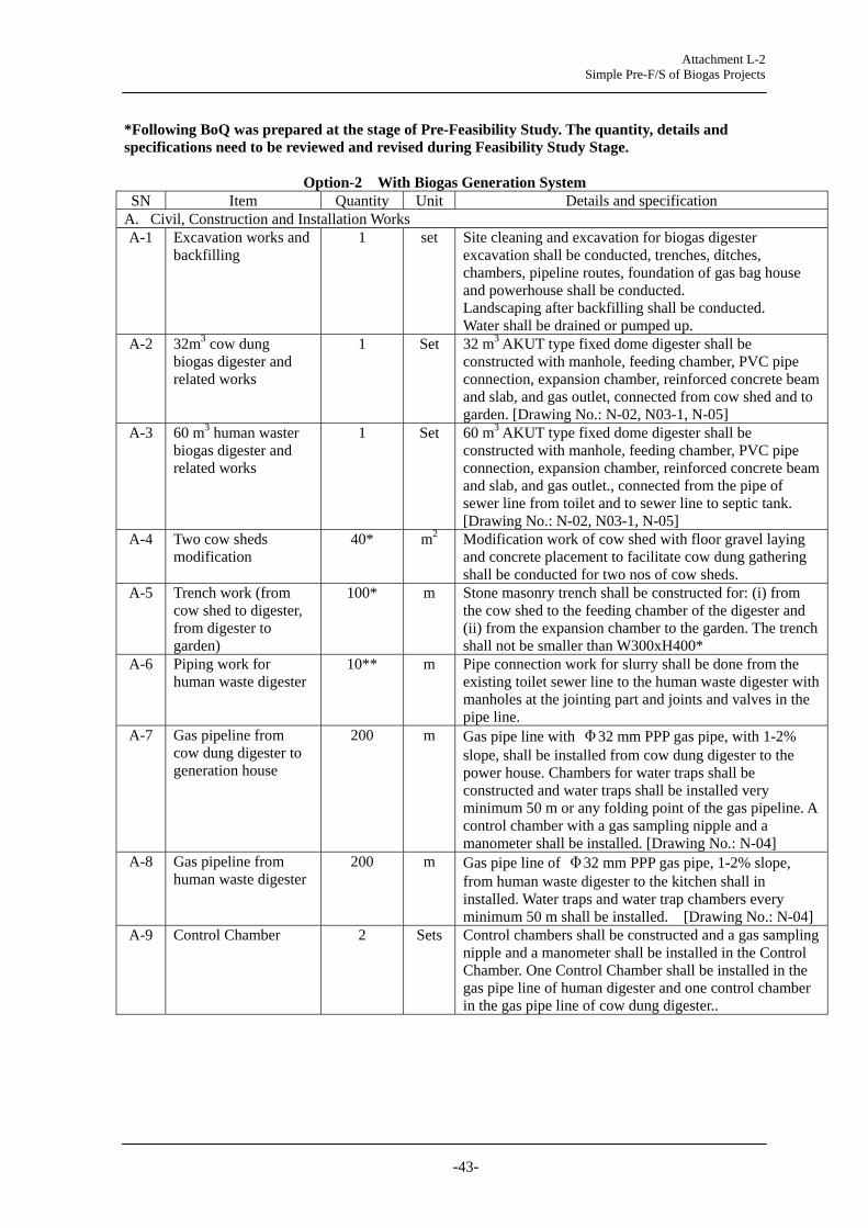
Attachment L-2 Simple Pre-F/S of Biogas Projects
-43-
*Following BoQ was prepared at the stage of Pre-Feasibility Study. The quantity, details and specifications need to be reviewed and revised during Feasibility Study Stage.
Option-2 With Biogas Generation System SN Item Quantity Unit Details and specification
A. Civil, Construction and Installation Works A-1 Excavation works and
backfilling 1 set Site cleaning and excavation for biogas digester
excavation shall be conducted, trenches, ditches, chambers, pipeline routes, foundation of gas bag house and powerhouse shall be conducted. Landscaping after backfilling shall be conducted. Water shall be drained or pumped up.
A-2 32m3 cow dung biogas digester and related works
1 Set 32 m3 AKUT type fixed dome digester shall be constructed with manhole, feeding chamber, PVC pipe connection, expansion chamber, reinforced concrete beam and slab, and gas outlet, connected from cow shed and to garden. [Drawing No.: N-02, N03-1, N-05]
A-3 60 m3 human waster biogas digester and related works
1 Set 60 m3 AKUT type fixed dome digester shall be constructed with manhole, feeding chamber, PVC pipe connection, expansion chamber, reinforced concrete beam and slab, and gas outlet., connected from the pipe of sewer line from toilet and to sewer line to septic tank. [Drawing No.: N-02, N03-1, N-05]
A-4 Two cow sheds modification
40* m2 Modification work of cow shed with floor gravel laying and concrete placement to facilitate cow dung gathering shall be conducted for two nos of cow sheds.
A-5 Trench work (from cow shed to digester, from digester to garden)
100* m Stone masonry trench shall be constructed for: (i) from the cow shed to the feeding chamber of the digester and (ii) from the expansion chamber to the garden. The trench shall not be smaller than W300xH400*
A-6 Piping work for human waste digester
10** m Pipe connection work for slurry shall be done from the existing toilet sewer line to the human waste digester with manholes at the jointing part and joints and valves in the pipe line.
A-7 Gas pipeline from cow dung digester to generation house
200 m Gas pipe line with Φ32 mm PPP gas pipe, with 1-2% slope, shall be installed from cow dung digester to the power house. Chambers for water traps shall be constructed and water traps shall be installed very minimum 50 m or any folding point of the gas pipeline. A control chamber with a gas sampling nipple and a manometer shall be installed. [Drawing No.: N-04]
A-8 Gas pipeline from human waste digester
200 m Gas pipe line of Φ32 mm PPP gas pipe, 1-2% slope, from human waste digester to the kitchen shall in installed. Water traps and water trap chambers every minimum 50 m shall be installed. [Drawing No.: N-04]
A-9 Control Chamber 2 Sets Control chambers shall be constructed and a gas sampling nipple and a manometer shall be installed in the Control Chamber. One Control Chamber shall be installed in the gas pipe line of human digester and one control chamber in the gas pipe line of cow dung digester..

Attachment L-2 Simple Pre-F/S of Biogas Projects
-44-
SN Item Quantity Unit Details and specification A-10 Gas holder bag 2 Sets Minimum 20 m3 gas bags made of Polyvinyl chloride
(PVC) or Isobutylene Isoprene Rubber (IIR) shall be installed and connected from the gas pipe line. One gas bag shall be connected to the kitchen cooking stoves and other shall be connected to engine generator. Leakage test shall be conducted. The material of gas bag shall be resistant to acid and alkali corrosion, resistance to wear and friction. Life span shall be more than 10 years. Suitable temperature at 0-50 oC.
A-11 Biogas flow meter 4 Sets The gas flow meter recording in m3 with one decimal place shall be installed one for the outlet of cow dung digester, one for the outlet of human waste digester, and two for the gas bags. Nominal flow rate shall be up to 2.0 m3/h. Maximum working pressure shall be more than 10 kPa. Pressure loss shall be ≤200Pa.Air tightness shall have no leakage under 10 kPa. In addition, 3 sets of the same flow meter shall be supplied for the replacement purpose.
A-12 Biogas filtering unit 2 Sets Activated carbon filter units to remove hydrogen sulfide, more than 99% purifying efficiency shall be installed for the cow dung digester and human waste digester. The unit container material shall be durable for H2S corrosion.
A-13 Manometer 3 Sets Manometers of highly resistant to corrosion shall be supplied and installed, one in the control chamber of cow dung digester, one in the control chamber of human waste digester, and one in the kitchen.
A-14 Gas Valve 2 Sets Gas valves shall be installed to stop gas flow from the gas bags.
A-15 Gas holder house 30 x 2 m2 Stone masonry and zing roof gas holder house shall be constructed. The house shall have ventilation and warning sign of leakage. Door shall be rocked.
A-16 Biogas stove 4 Nos Biogas stove with double burner, with automatic starter switches and 2 meters of hosepipe. Each burner shall have heat load more than 2.5 kW, gas consumption rate 0.4-0.6 m3/h, and efficiency more than 57%.
B. Mechanical and Electrical Works B-1 Power house 30 m2 New power house with a grill fence wall, zinc roofing
and door rock shall be constructed to install biogas engine and generator and electrical equipments near the kitchen or appropriate location as the user will assign.
B-2 Energy meter 1 Nos. An energy kWh meter with one decimal shall be supplied and installed.
B-3 Distribution panel 1 Set The single phase distribution board with MCB and safety control shall be installed to supply and switch power from biogas generator to the load.
B-4 Change over switch 1 Set Manual change over switch shall be installed to interchange the power from grid or from biogas generation system.
B-5 Air Inlet Valve 1 Sets Solenoid air inlet valve shall be installed to switch off gas in the event of generator stoppage.
B-6 Power House wiring 1 Set Internal wiring shall be done for power house with single-core or multi-core, cross-linked polyethylene (XLPE) insulated, PVC sheathed cables with stranded copper conductors.
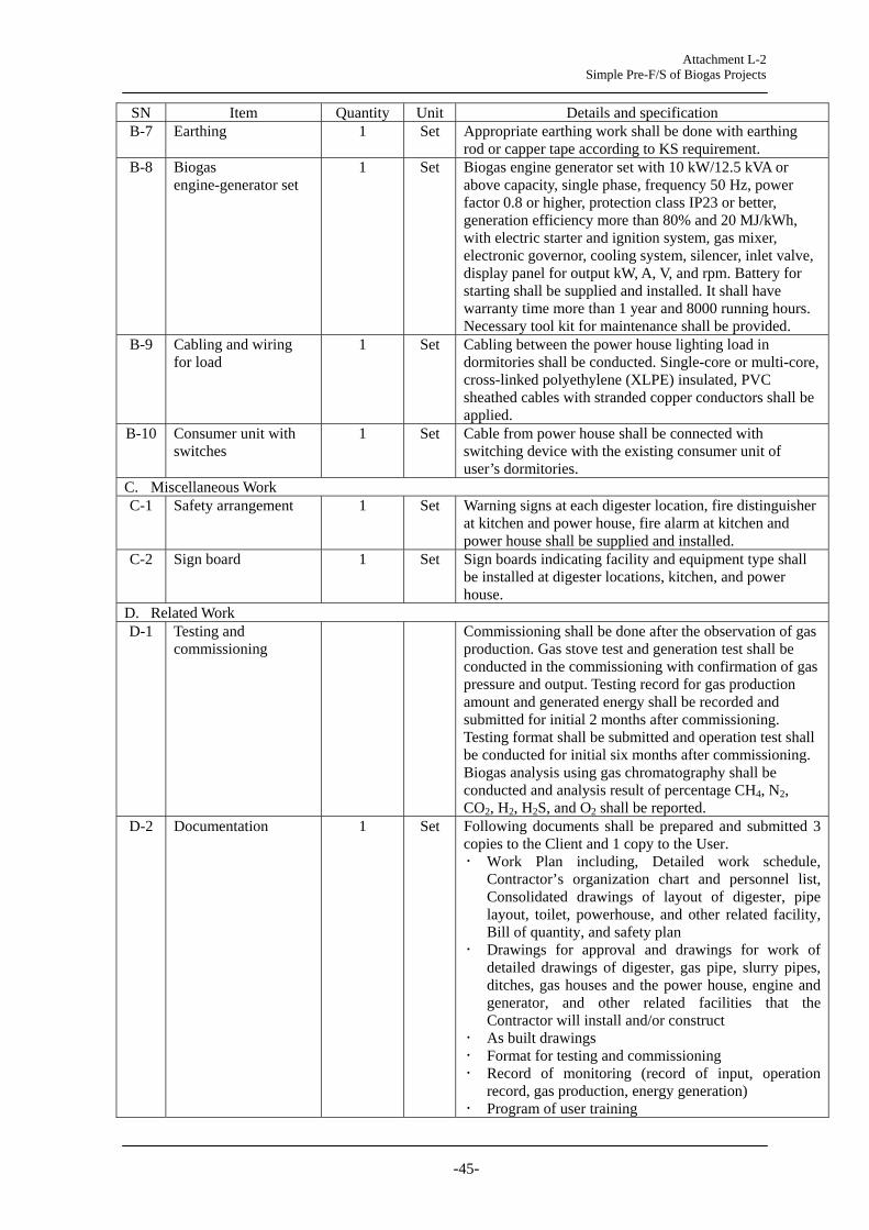
Attachment L-2 Simple Pre-F/S of Biogas Projects
-45-
SN Item Quantity Unit Details and specification B-7 Earthing 1 Set Appropriate earthing work shall be done with earthing
rod or capper tape according to KS requirement. B-8 Biogas
engine-generator set 1 Set Biogas engine generator set with 10 kW/12.5 kVA or
above capacity, single phase, frequency 50 Hz, power factor 0.8 or higher, protection class IP23 or better, generation efficiency more than 80% and 20 MJ/kWh, with electric starter and ignition system, gas mixer, electronic governor, cooling system, silencer, inlet valve, display panel for output kW, A, V, and rpm. Battery for starting shall be supplied and installed. It shall have warranty time more than 1 year and 8000 running hours. Necessary tool kit for maintenance shall be provided.
B-9 Cabling and wiring for load
1 Set Cabling between the power house lighting load in dormitories shall be conducted. Single-core or multi-core, cross-linked polyethylene (XLPE) insulated, PVC sheathed cables with stranded copper conductors shall be applied.
B-10 Consumer unit with switches
1 Set Cable from power house shall be connected with switching device with the existing consumer unit of user’s dormitories.
C. Miscellaneous Work C-1 Safety arrangement 1 Set Warning signs at each digester location, fire distinguisher
at kitchen and power house, fire alarm at kitchen and power house shall be supplied and installed.
C-2 Sign board 1 Set Sign boards indicating facility and equipment type shall be installed at digester locations, kitchen, and power house.
D. Related Work D-1 Testing and
commissioning Commissioning shall be done after the observation of gas
production. Gas stove test and generation test shall be conducted in the commissioning with confirmation of gas pressure and output. Testing record for gas production amount and generated energy shall be recorded and submitted for initial 2 months after commissioning. Testing format shall be submitted and operation test shall be conducted for initial six months after commissioning. Biogas analysis using gas chromatography shall be conducted and analysis result of percentage CH4, N2, CO2, H2, H2S, and O2 shall be reported.
D-2 Documentation 1 Set Following documents shall be prepared and submitted 3 copies to the Client and 1 copy to the User. Work Plan including, Detailed work schedule,
Contractor’s organization chart and personnel list, Consolidated drawings of layout of digester, pipe layout, toilet, powerhouse, and other related facility, Bill of quantity, and safety plan
Drawings for approval and drawings for work of detailed drawings of digester, gas pipe, slurry pipes, ditches, gas houses and the power house, engine and generator, and other related facilities that the Contractor will install and/or construct
As built drawings Format for testing and commissioning Record of monitoring (record of input, operation
record, gas production, energy generation) Program of user training

Attachment L-2 Simple Pre-F/S of Biogas Projects
-46-
SN Item Quantity Unit Details and specification User Manual Record of user training and user’s understanding List of consumables and spare parts and supplier’s
contact list Bills of Quantity and Cost
D-3 User training 1 Set User training with training program and shall be conducted at least four persons (operators and supervisor) assigned from the user. User manual shall be provided to the Client and the User.
D-4 Technical support 1 Set Technical supports shall be provided for initial one year for operation and maintenance of the user from the date of commissioning.
D-5 Supply of maintenance tools and spare parts
1 Set The maintenance tools necessary for operation and maintenance and spare parts including filtering materials and engine-generator parts for replacement shall be provided for 3 years operation.
D-6 Transportation 1 Set The transportation shall cover all supply of materials and equipment.
D-7 Labor 1 Set The labor shall cover all construction, civil , electrical, installation works.
D-8 Administration 1 Set Administration shall cover all administration works including communications and documentations.
*The quantity and size is rough estimate in Pre-FS. Those shall be reviewed and revised according to the result of feasibility study. **If toilet sewer line is the same as waste water from shower room, additional independent sewer line exclusive for toilet shall be constructed.
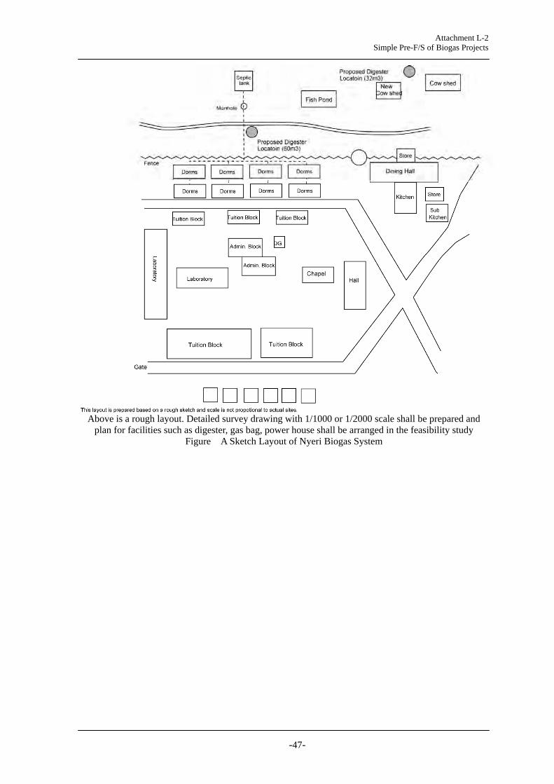
Attachment L-2 Simple Pre-F/S of Biogas Projects
-47-
Above is a rough layout. Detailed survey drawing with 1/1000 or 1/2000 scale shall be prepared and plan for facilities such as digester, gas bag, power house shall be arranged in the feasibility study
Figure A Sketch Layout of Nyeri Biogas System

Attachment L-2 Simple Pre-F/S of Biogas Projects
-48-
Scope of Works for Nyeri Biogas Project (for both Option-1 and Option-2)
1 General
The Client conducts construction supervision at all times. The Contractor shall follow Kenyan Standards (KS) and related international and national standards such as the building code and IEEE. All applied standard shall be currently effective.
The Contractor shall assign a manager in charge of the overall project management, and the proposed manager’s CV shall be submitted to the Client for approval.
Work Plan shall be prepared and submitted for approval of the User and the Client. It shall include but not be limited to: Detailed work schedule Contractor’s organization chart and personnel list Consolidated drawings of layout of digester, pipe layout, power house, toilet, and other
related facility Bill of quantity Drawings of digester, pipe, power house, generator, and other related facilities that the
Contractor will install and/or construct Safety plan
2 Concrete and Other Works
(1) Cement, sand, and aggregate
The cement shall be obtained from an approved manufacturer. The Portland cement shall be delivered to the site in sealed kraft bags which shall be clearly marked with the name of manufacturer, place of production, the type of cement, the year and month produced and the weight contained. The cement must be fresh, without lumps and stored in a dry place. Bags of cement shall never be stacked directly on the floor or against the walls to protect the cement from absorbing moisture before use.
All aggregates and sands shall be free from earth, clay, chalk, lime, peat, loam, soft clay of shale or decomposed stone, vegetable and organic matter and other impurities. The aggregates shall be hard and dense, and spherical or cubical in shape. Provisions shall be made at the site for the separate storage of fine and coarse aggregates, as well as of each size of coarse aggregates, in such a manner as to avoid contamination of the aggregates by foreign materials. If aggregates are dirty, they should be washed with clean water.
Gravel size shall not be too big or too small. Individual gravel diameter shall not be greater than 25% of the thickness of concrete product where it is used. Gravel should not be larger than 2 cm in size.
The quantity of impurities such as mud shall be tested using a bottle test. Fill a bottle or glass with 1/3 sand and 2/3 water and stir vigorously. Leave the bottle in a stationery position to allow the sand to settle. The particles of sand are heavier than those of mud and will settle down quickly. After 60 minutes, measure the layers of mud and sand inside the bottle and compare the height of mud layer against the height of mud and sand layers as a percentage. A maximum of 3% of mud in the sand shall be permissible. If mud and other impurities are more than 3% of the sand, then the sand shall not be used and shall be discarded.
Water for washing aggregates and sands, and mixing and curing of concrete, shall be taken from an approved source and shall be clean and free from deleterious substances including salt, oil, alkali, organic matter and others that may impair strength, appearance and durability of concrete.
If cobble-sized stones are used, individual stone diameter of 7.5 - 30 cm shall be used for masonry work. The stones shall be clean, solid and of good quality; and shall be washed with clean water if they are dirty.

Attachment L-2 Simple Pre-F/S of Biogas Projects
-49-
The concrete shall be arranged according to “KS02-594:1986 Specification of Concrete” or other relevant standard(s) approved by the Client. The compressive strength after 28 days shall be more than 20 N/mm2 otherwise specified. The concrete mixing property shall be submitted and concrete test shall be conducted.
The same clean containers shall be used and the containers shall not be changed during the work to measure the volumes of concrete.
Concrete bases, slabs, beams, and forms and all the reinforcement shall be prepared and shall be ready before the concrete is mixed. All earth bases and forms shall be wet to prevent absorption of water from the concrete, but excess water content in the mixture shall be avoided. All concrete shall be placed within one hour of mixing the cement with water.
Cement shall be prepared according to “KS EAS 19-1:2001 Composition, Specifications and Conformity Criteria for Common Cement” or other relevant standard(s) approved by the Client.
Waterproof cement mortar shall be applied. The mixing and application of a waterproofing agent shall be in accordance with the manufacturer's instructions. The cement mortar shall be applied carefully using steel trowel. The sand to be used in the cement mortar shall be clean, hard, solid and durable and shall not contain harmful amounts of dust, mud, organic matters or other objectionable matter.
Waterproof cement shall not dissolve in water, but shall float when poured into a bucket of water.
(1) Reinforcement
Concrete reinforcement shall be more than the sufficient amount as indicated in the Drawing, which shall be proposed by the Contractor.
Reinforcement steel used in reinforced concrete shall be deformed steel bars, complying with KS573:2008 High Yield Steel Bars for the Reinforcement of Concrete-Specification.
Reinforcement steel shall be stocked on the site, separated into the various sizes in such a manner that the steel does not get contaminated with deleterious matter. The number, size, form and position of all steel reinforcing bars, ties, links, stirrups and other parts of the reinforcement shall be in accordance with the approved drawings and they shall be kept in the correct position and with the required cover without displacement during the process of compacting the concrete in place.
Cutting, bending and splicing of the reinforcement bars shall be carefully carried out in accordance with the shop drawings submitted to the Client for approval.
The bars shall be bent cold in a manner which will not injure the material. Any ties, links or stirrups connecting the bars shall be tauten so that the bars are properly braced and the inside of hooks and bends shall be in actual contract with the bars around which they are intended to fit. Bars shall be bound together with the best black annealed soft-iron wire and the binding shall be twisted tight with pliers. The free ends of binding wire shall be bent inwards.
Before any steel reinforcement is fabricating, any loose mill scale, loose rust and any oil, grease, mud or other deleterious matter shall be removed.
(2) Concrete placement
Before placing any reinforcement bars on the surfaces of earth, gravel, etc., a layer of concrete shall be worked into the cleaned surface to a thickness of 5 cm. Before placing concrete on foundations, the Contractor shall remove from all such surfaces; soil, objectionable coatings, loose or unsound fragments of rock, earth, mud, debris, and stagnant water, and shall keep such surfaces clean and free from stagnant water during concreting operations.
All concrete and mortar shall be placed and compacted within one hour after being mixed; and no partially set material shall be used in the work. The placing of concrete in individual

Attachment L-2 Simple Pre-F/S of Biogas Projects
-50-
structural members shall be continuous without stopping up to an approved prearranged construction joint or until the member is completed. Concrete placing shall be carried out rapidly to prevent occurrence of cold joints under hot weather conditions.
The Contractor shall take adequate measures to cure the concrete. These shall include covering the concrete with a moist curing mat or other effective means which shall be kept damp continuously and not exposed to sunlight for a minimum period of seven (7) days after casting.
The finished faces of all concrete works shall be sound, solid and free from honeycombing, protuberances and blemishes. No plastering of imperfect concrete faces shall be allowed and any concrete that is defective in any way shall be cut out and replaced to such depth or be made good.
(3) Bricks and blocks
B ricks shall be prepared according to “KS 02-300:1983 Specification for burnt building bricks”, and blocks shall be prepared according to “KS 02-547 Specification for burnt Clay Blocks”, or other relevant standard(s) approved by the Client.
If the Contractor applies precast masonry units, the Contractor shall apply “KS 02-625: 1986 Specification for Precast Masonry Units” or other relevant standard(s) approved by the Client.
The bricks shall be of the best quality of their respective kinds. They shall be hard, square, sound, thoroughly well burnt, true to shape, uniform in size, shape and texture, free from lime and hair cracks, uniform in colour, and clean. The porosity shall in no case exceed 20% by weight, though in the case of engineering bricks not more than 5% will be allowed. Before any order for bricks is made by the Contractor, samples must be submitted to the Client for approval. Manual labour shall be employed in unloading and stacking bricks on delivery. No broken, chipped or cracked bricks shall be brought to the Site.
Bricks shall be built in level courses using bricks of the quality or description specified and to the dimensions shown on the approved drawings. Walls are to be built up in a uniform manner and no one portion raised more than 1 m above another at one time, being racked up and not toothed. All bricks shall be perpendicular, kept strictly plumb and square and the whole properly bonded together so that there are no continuous vertical joints through any two courses of brickwork. No broken bricks will be allowed except where necessary to form proper bonds. The mortar for brickwork shall be, unless otherwise specified, cement and sand mixed in the proportion of 1:3 generally.
Immediately before use, bricks are to be immersed in fresh water and thoroughly wetted. Before continuing partly completed work, the exposed bed shall likewise be wetted. All beds and joints are to be completely filled with cement mortar notwithstanding any local or common custom to the contrary. Where the brickwork is specified to be unpainted, the joints on exposed faces are to be ironed in as the work proceeds and special care is to be taken to give the whole of the joints an even colour. Faces of brickwork due to be plastered shall have joints raked out and left open to form a key for plastering.
Concrete bricks can also be made on-site from cement, sand and ballast chipping if fired bricks are not available or are too expensive. The volume ratio of concrete bricks shall be 1:3:4 for cement: sand: gravel respectively.
Concrete bricks shall be strong (good ratio, mixing, and proper compaction when making) and shall uniformly have a regular shape and size. Concrete bricks shall be cured for at least 7 days before they are used.
The concrete bricks shall have a uniform size of:
23 x 11 x 9 cm for smaller - radius digesters (up to 32 m³), and
25 x 12 x 10 cm for larger - radius digesters (above 32 m³).

Attachment L-2 Simple Pre-F/S of Biogas Projects
-51-
Bricks with a thickness of less than 9 cm shall not be used.
3 Biogas Digester
The following are the instructions for construction of a general fixed dome type digester.
When the instructions mention “mixing chamber” and “expansion chamber”, the digester utilizes cow dung as feedstock. A toilet connected digester does not have these components and is connected directly with the sewer line.
There are several types in the design of biogas digester. Followings are the general description that the Contractor should follow, referring to AKUT fixed dome biogas digester developed by GIZ. Details may be changed according to specific design of digester.
(1) Finalization of Biogas Location
The finalized location of the digester shall be approved by the User and the Client. The following items shall be considered to determine the finalization location:
· The edge of the foundation of the digester shall be at least two meters away from any other structure to avoid risk of damage during construction.
· The location of digester shall be apart from trees to prevent damage.
· The digester shall be at least 10 meters away from groundwater wells or surface water bodies to prevent water pollution.
· A fixed dome biogas plant shall be constructed as follow: round wall and expansion chamber made of either brick, block or stone, dome made with plain concrete (for small digester less than 10 m3), brick or block, slabs and beam made with reinforced concrete, foundation made with concrete, and feeding chamber made with either stones or bricks.
(2) Marking of Digester Location
After finalization of location, the site layout shall be marked on the ground surface with wooden stakes, rocks, chalk or other materials. The following is an example of a marking method.
1) First, stick a small peg in the ground at the centre spot of the digester.
2) Level the ground and determine the centre line of the digester, feeding chamber, and expansion chamber.
3) Define the reference level. Assume that the ground level is the reference level and indicate this in a drawing. The top of the dome (outer surface) shall be exactly at ground level.
4) Attach a cord to the peg to represent the radius of the digester. Mark the circumference by moving the end of the cord in circular motion.
5) Mark the feeding chamber inlet pipe, feeding chamber, and gas piping.
6) Insert a stick or wooden peg in the leveled ground at the centre of the proposed digester pit. With the help of the stick/peg and cord prepared earlier, mark the circumference of a circle to indicate the area to be dug from the centre point where the central line meets the perimeter line. Draw a tangent to the circle and measure a suitable length.
7) Mark the manhole, ensuring that the inner size.
8) Draw horizontal parallel lines from points on either side of the tangent, which will meet the dome from the centre point where the central line meets the perimeter line. Measure the length of the outlet and the thickness of the wall to define the outer dimension.
9) Check the size diagonally to ensure that the corners are exactly at 90°. Use colored powder to mark the dimensions.
Attachment L-2 Simple Pre-F/S of Biogas Projects
-52-
10) After the site layout is marked, the User should review the selected location again to ensure that the best site has been chosen and the digester will not interfere with user’s activities.
(3) Excavation of Digester
Excavation of the digester pit shall be started after layout is approved. Tools such as crow-bars, picks, spades, shovels and baskets shall be provided by the Contractor. Digging shall be done as per the dimensions fixed during layout. The following conditions shall be maintained:
· f the water table is high and digging to the required depth is difficult, a deeper pit has to be constructed near the digester pit
· Water accumulated in the digester pit has to be drained from the pit through underground pipes or pumping.
· After the required dimension and depth of digging is attained, the work of leveling and ramming the base shall be done. The pit bottom must be leveled and the earth must be untouched.
· Horizontal poles shall be placed at the ground level, crossing each other at 90 degrees at the centre. It shall be ensured that the poles rest on leveled ground.
· For safety, the pit walls shall be vertical and stepped from the ground surface. For each meter in depth excavated, the stepping shall be shifted one meter away from the center of the excavation. If the soil lacks cohesion and the angle of repose needs more slope cutting, scaffolding may be needed.
· Excavated soil shall be placed at least one meter away from the edge of the pit and steps, so that it does not fall back into the pit during works.
· It is not recommended to construct the digester at or below the groundwater table elevation. The earth base of the excavation shall be compacted to attain at least the same degree of consolidation as undisturbed soil in the site. Compaction shall be done using a rammer or compaction tools.
(4) Construction of Digester
The ring foundation and the conical bottom shall be prepared. A conical shape for the bottom slab is more stable and provides additional volume.
1) Foundation
· The digester foundation shall be laid using cobblestones and/or gravel as aggregate then filled with concrete. The foundation shall not be less than 15 cm in thickness and the mixing ratio shall be 1:3:4 for cement: sand: gravel respectively.
· The foundation concrete shall be cured for at least two days.
· The foundation ring where the brick and concrete work settles shall be shaped horizontally and shall be levelled before filling. For larger sizes of biogas plants (32 m³ and above) and on weak ground, the foundation ring beam shall be placed with reinforcement bars.
· Horizontal measurements are done with the centre pipe. The 0.5" GI gas pipe shall be placed exactly vertically. The positioning of this center pipe shall be ensured by using a spirit level and adjusting with binding wire fixed at four pegs in the soil on the rim of the excavation. After confirmation of the level, the vertical pipe shall be checked with a plumb to ensure it is still in the exactly vertical position.
· A string or wire shall be attached to the vertical pipe. The length of this wire shall be much longer than the dome diameter.

Attachment L-2 Simple Pre-F/S of Biogas Projects
-53-
· The foundation slab shall be placed up to completion at one time, after mixing enough concrete for the whole slab. The slab shall be exactly leveled with the pegs to determine the level of the concrete at every point around the base. If the slab is not leveled, the distribution of weight will not be balanced and the structure may crack.
2) Digester Wall
· Immediately after casting the slab, the first layer of stonework has to be put into the freshly placed concrete to obtain bonding between foundation and walling.
· The first row of bricks shall be placed on a firm, untouched and level foundation. Subsequent rows shall be positioned on their lengths so that the wall thickness is maintained. The wall thickness shall be maintained at not less than 23 cm.
· he cement mortar for joining bricks shall be mixed in the ratio of 1:4 for cement: sand respectively.
· To construct the digester wall, the radius shall be kept constant using a guide square fixed at the centre GI pipe. All blocks shall be laid out properly with the assistance of the radius square. The radius square shall always be leveled, and a spirit level shall be fixed on the square every time blocks are laid. The dimensions shall be checked and corrected at every stage by measuring the vertical distance from the reference line.
· After the round-wall reaches the correct height, both the inside and outside of the wall shall be plastered carefully with a smooth layer of cement mortar with a mixing ratio of 1:4 for cement: sand respectively. Before application of cement mortar, the wall surface shall be cleaned and moistened, after which the plaster shall be applied in one coat of about 2 cm.
· After every three to four layers of blocks, backfilling and compacting should be done so that the completed part is properly reinforced by the soil. The backfilling between wall and pit-side shall be compacted with great care, not sooner than 12 hours after brick course placement to allow the cement mortar to cure. Earth shall be well compacted by adding water and carefully ramming along the digester.
· The feedstock inlet pipe (or toilet pipe in the case of toilet connected digester) shall be placed in position when the round-wall is 30-36 cm high, at a slope of 45°), taking into consideration the location of the inlet mixing chamber.
· At the opposite of the main feedstock inlet pipe, a window must be left for slurry flow to the expansion chamber. After the space for the outlet is dug out, construction of the vertical wall shall proceed, incorporating the outlet steps. In the case of toilet connected digester, outlet pipe shall be connected to a sewer line for septic tank and adequate space for the pipe shall be left.
3) Dome (Gas holder)
· To construct the spherical dome, another square shall be used to create a bowl shape. The square shall be fixed at the central GI pipe, with proper positioning and leveling. The radius square shall be adjusted during the dome construction by fastening and correcting the distance from the guide pipe. For plastering, 2 cm shall be added to the radius.
· A nail at the head of the square is used to mark the exact distance for brickwork construction. Each brick of the dome is laid against the nail of the radius stick, keeping the top of the brick in the same slope as the direction of the radius stick. The inner edge of the brick shall always form a right angle with the radius stick, and the brickwork will automatically rise in spherical shape.
· The mortar mixing ratio for dome brick laying shall be 1:3 for cement: sand respectively.
· The spherical wall ends with the manhole ring beam. Above this ring beam the neck shall
Attachment L-2 Simple Pre-F/S of Biogas Projects
-54-
be constructed in masonry work according to the detailed measurements in the drawing. The neck shall be constructed up to completion at one time to avoid any cracks. Flemish bond shall be used, whereby the orientation of stones is changed from row to row. The best stones shall be selected especially for the neck structure and a perfect jointing shall be done for the neck. The dome shall be durable with internal gas pressure on the spherical structure and the neck. The neck shall be able to withstand the internal gas pressure by its own internal structure. A main gas outlet pipe shall be applied at the neck.
· A lid shall be cast inside the neck structure. The lid shall be reinforced concrete. Four (4) steel handles shall be applied for a concrete lid. The thickness shall be 18 to 20 cm. The gap between the neck and lid shall not exceed 2 cm as a large gap will not be gas-tight. Sealing shall be done later with moist clay. After clay sealing, weak mortar with mixing ratio of 1:8 for cement: sand respectively shall be applied on the top of the lid peripherally for top sealing.
· After casting the lid and feeding feedstock, a water jacket covering the lid of the manhole shall be applied to prevent lid sealing from drying up and for leakage detection.
· The outside of the dome shall be covered with a layer of plaster before covering with earth. Cement plaster shall not be applied under sunlight. The mixing ratio of mortar for rendering plastering shall be 1:5 for cement: sand respectively.
· Before mortar application, the surface of the wall shall be cleaned and moistened. Plaster of 2 cm thickness shall be applied all over the surface of the dome. The plaster shall be cured for more than 12 hours before backfilling.
· After above rendering, the inside plaster of the dome and neck shall be done with the most accurate workmanship to secure gas tightness. Special attention shall be given to ensuring that the surface area of the dome and neck forms a unity, and every inside plaster course shall be done up to completion at one time.
· A wooden trowel with smoothened corners shall be used alongside a conventional trowel to execute a smooth and even surface. All mortar that falls down shall not be used for the dome and neck.
· Before application of the first layer, the surface of the wall shall be cleaned well, and excess mortar removed before starting plaster work. The quality of the sand for plastering the dome shall be “best of the best” and no impurities shall be allowed. The sand for plastering shall also be sieved prior to mixing with cement.
· Seven steps shall be taken for plastering of the dome: (i) Cement-water flushing, (ii) preparation of mortar in 1:4 mixing ratio for cement: sand respectively , (iii) Cement-water flushing, (iv) plaster with water proof compound, with mixing ratio of 1:4 for cement: sand respectively, (v) Cement–water flushing with water proof compound, (vi) plaster with water proof compound, with mixing ratio of 1:3 for cement: sand respectively, and (vii) Cement–water finish with water proof compound. Undertaking the seven steps will ensure that the final cement flushing appears as a very smooth and shiny surface.
· Backfilling shall be in layers of less than 30 cm, and then compacted softly. Any damage to the digester wall shall be avoided. The backfill material must be compactable, and clay or black cotton soil shall not be applied.
4 Piping Works and Ditches
Piping works shall be conducted according to the work plan. The layout shall be approved by the User and the Client.
All pipe laying works shall be carried out by experienced personnel. The pipes shall be correctly
Attachment L-2 Simple Pre-F/S of Biogas Projects
-55-
centered and aligned horizontally and vertically just prior to jointing with the mating socket. Any pipe found to be defective shall be marked, removed and replaced. Any damage to pipe linings or coatings shall be repaired by the Contractor. The pipe shall be corrosion resistant and tolerant of high concentrations of methane gas and hydrogen sulfide.
The pipes and fittings shall be of the same brand. They shall be checked and confirmed not to have any leakages. Pipe manufacturer’s specifications and recommendations shall be strictly followed for solvent, welded and electrofusion joints.
After the installation of pipeline, the Contractor shall investigate all the gas lines and pipe joints for any blockages and leaks, and conduct repairs.
The Contractor shall check the pipeline for leakage and secure approval from the User before backfilling. All valves and connections shall be checked to ensure there are no leakages.
The piping for gas shall have a slope of 1/100-2/100 (1-2%) to collect and direct moisture towards water traps. Avoid sagging in the pipe line. A moisture remover shall be installed.
Pressure test on the piping system shall be done after the whole system has been laid and the manometer has been installed. This shall be done before backfilling of the pipe trenches.
Both PVC and PPR pipes shall be laid at least 30 cm below the ground level. Special conditions may require deeper installation. Proper compacting during backfilling shall be done in layers, after every 20 cm to protect pipes.
Manholes shall be installed with metal cover or concrete cover with a steel bar handle at intervals of at least 50 m on the pipe line and at corners along the pipe route. A pressure test unit and gas sampling nipple shall be applied with ball cock.
A manometer shall be provided with a pressure scale so that the User can know the possible amount of gas usage.
For cow shed connected digester, ditch from the cow shed shall be modified so that automatic transportation of cow dung and urine is possible by gravity. A ditch shall be arranged to channel and transport feedstock by gravity. The elevation of ditches between the cow shed and digester shall allow to flow downstream from the cow shed towards the digester. If not, modification work shall be done.
Biogas slurry shall be supplied to the garden by gravity. The location of the garden shall be confirmed to be at lower elevation than expansion chamber of digester. A ditch connecting digester expansion chamber to the garden, with a gate along the channel shall be constructed.
For toilet connected digester, the pipe from sewer line shall be connected to digester inlet pipe. Digester outlet pipe shall be connected with a sewer line to the septic tank. Manholes shall be provided for the connection parts.
For toilet connected digester, a separate pit latrine shall be provided for persons taking antibiotics.
5 Steel and metal works
The Contractor shall furnish and install miscellaneous embedded metal works, such as embedded metal frames for duct cover, anchor bolts with accessories, steel pipes for duct, light gage steel ceiling material with zinc chromate metal finish or hot-dipped galvanized, etc.
The Contractor shall furnish and install miscellaneous non-embedded metal works, such as steel-made chain-link fence with pole, entrance gate, etc. All exposed steel surfaces shall be hot-dip galvanized metal.
Oil paint shall be applied onto two layers of primary anticorrosive paint. Sufficient time shall be allowed for drying between each new coat according to manufacturer’s instructions.
Rust on metal surfaces, and oil and dirt on surfaces shall be thoroughly removed before installing.
Attachment L-2 Simple Pre-F/S of Biogas Projects
-56-
6 Electrical works (For Option-2 with generation system)
Wiring work shall be conducted in accordance with “KS662: 2002 Kenya Wiring Regulations”.
Insulated cables shall apply “KS 453:2000 Specification for PVC-insulated cables for Electric Power and Lighting”.
All power cables shall be of single-core or multi-core, cross-linked polyethylene (XLPE) insulated, PVC sheathed cables with stranded copper conductors. Power cables shall have ample current carrying capacity and shall duly withstand the maximum prospective fault current for a duration of time.
Each cable shall be fitted with a cable identification label at each end. The cables shall be continuous between terminals, and no junction shall be made in the cable ducts and conduits. The cables shall be laid in the cable ducts or conduits after they have been cleaned. Oil or grease shall not be used as a lubricant for cable laying work, but an approved compound may be used for this purpose.
Where the cables and wires are installed in the conduits, they shall be pulled into a conduit as a bundle to avoid twisting and abrasive actions caused by single conductor pulling.
At least 10% spare terminals shall be provided in the terminal blocks.
Proper earthing shall be done with grounding electrodes. Each electrode shall be complete with approved non-ferrous clamps for the connection of earthing conductors. The measurement of each group of grounding electrodes and earth grid shall be provided and back filling shall only be undertaken after inspection.
The Contractor shall provide detailed guideline for specification, operation and guideline of engine-generator provided from manufacturer.
7 Excavation, soil and waste
Before excavation, the Contractor shall clear and dispose all rubbish and/or any other objectionable matter within the Site. This shall include the removal of existing foundations and other obstructions interfering with the project work, and burning or otherwise disposing of all such materials.
The slope and bottom of all excavation shall be trimmed and cleared of all loose or decomposed material and finished with firm and smooth perpendicular, level, or inclined surfaces as required. The surfaces of the excavation shall be protected from deterioration and be kept clear and uniform. The excavated trench or pit shall be kept well drained of water until and during backfilling operation.
Before all excavation, the contractor shall obtain approval from the user, specifically regarding the location to place excess soil. Avoid accidents while digging near the sides as soil may collapse
If the soil is not suitable for use in embankment and backfilling, the Contractor shall obtain good quality soil for this purpose from borrow pits. The location and areas of borrow pits shall be proposed by the Contractor and approved by the User and the Client.
The soil shall be placed in not more than 30 cm layers evenly spread, and each layer shall be well compacted to attain at least the same degree of consolidation as undisturbed soil in the Site. The soil shall be dried or watered as required to have the optimum moisture content to attain the required consolidation. The surface of embankment and backfill after compaction shall have a slightly cambered surface where required to facilitate drainage.

Attachment L-2 Simple Pre-F/S of Biogas Projects
-57-
8 Safety arrangement
The Contractor shall provide insurance for workers. A copy of the certificate of insurance shall be provided to the Client.
Safety equipment shall be provided for all workers and related personnel in the construction site such as helmets and belts. All laborers shall be appropriately dressed for the working conditions to avoid accidents.
The construction site shall be clearly separated from outsiders by a fence or rope. Nobody other than related personnel or laborers shall enter the construction and installation site during works.
The Contractor shall provide maximum warnings to ensure fire hazards are managed. No cigarette smoking shall be allowed on site during works, especially after feedstock has been channeled to the biogas system.
The location of main facilities, such as digester, pipe line, gas bag, and generator shall be apart from traffic line and its extended line of any vehicles to avoid accidental shock.
Fire extinguisher and eye-catching warning sign with shall be attached in power house and other facilities that have possibility of fire.
9 Testing and commissioning
The Contractor shall perform testing and commissioning in the presence of the Client. Testing and commissioning shall be according to the format prepared by the Contractor and submitted for approval by the client before testing.
For biogas digesters connected to toilets, in addition to the feedstock supply from toilets, cow dung at 200 kg per digester shall be applied not less than three times to facilitate initial fermentation at the original stage.
10 User training
The Contractor shall provide user training to not less than three operator assigned by users’ representative. The Contractor shall conduct operation and maintenance work during the testing and commissioning period, with participation of users and provision of O&M training. The training period shall not be less than three weeks. The Contractor shall check the users’ understanding by using a questionnaire sheet and attach it in the report to the Client. A list of “Do’s and Don’ts” shall be provided and presented to users at the working place. The findings and challenges found in the process of user training shall be pointed out.
Proposed user training program shall be submitted to the Client for approval, before conducting the training.
The Contractor shall provide a list of spare parts and consumables, as well as contact addresses for the same, so that user can easily make contact whenever it is necessary.
If the system contains a digester connected to toilets, notification for toilet usage shall be provided and a briefing meeting shall be held with toilet users. The notification of toilet usage shall include but not be limited to: Do not flush excessive amounts of water (specify allowable amount) Do not use the toilets connected to the digester while taking antibiotics, use a separate
toilet instead Do not use detergents with disinfecting agents such as chlorine
Visual guidance shall be provided by pasting a laminated instruction paper on the wall of all entrances and exits of toilets.
User manual for operation and maintenance including daily routines, recording sheets, DOs,

Attachment L-2 Simple Pre-F/S of Biogas Projects
-58-
DON’Ts, trouble shooting, contact list for spare parts and consumables supply shall be provided and submitted for approval of the Client.
Safety instructions to users shall be provided, especially pertaining to the risk of explosion and toxicity of biogas aspiration.
11 Record and Documentation
The Contractor shall present his general work plan for approval by the Client.
The list of documents that the Contractor shall submit is as follows: Work Plan As built drawings Format for testing and commissioning Record of monitoring (record of input, operation record, gas production, energy
generation) Program of user training User Manual Record of user training and user’s understanding List of consumables and spare parts and supplier’s contact list

Attachment L-2 Simple Pre-F/S of Biogas Projects
-59-
Annex 2 Proposed Scope of Work for Feasibility Study of Nyeri Biogas Project 1. Introduction 1.1 Background and Objective Biogas produced in anaerobic digester can be applied both for the production of the electricity using engine-generator and cooking fuel for the replacement of fuelwood. The biogas generation system is a method of electricity generation utilizing biogas produced by methane bacteria as the energy source. Similar to natural gas or propane gas, biogas has heat value, and can therefore be utilized as energy. Although the unit heat value of biogas is smaller than that of fossil fuels, biogas can be used as a cooking fuel in the same way as LPG with some modification of cooking stoves. When it is connected to a gas engine or modified diesel engine, it provides rotative force for the generator, producing electricity. Since waste materials are used as feedstock for biogas systems and no fossil fuel is required, biogas is considered a renewable energy source. Strategic Master Plan 2013/2014-2017/2018 of Rural Electrification Authority (REA), Third Draft, stipulates that promotion of the use of renewable energy sources including biomass is one of REA’s roles. In the strategic objective to develop and promote renewable energy sources, the strategic plan includes a target to develop and promote biogas and biomass systems for institutions. Pre-Feasibility Study for Biogas Projects was therefore prepared to assess the technical and economic feasibility of biogas projects in six schools in Kenya by the Working Group of REA. In the Pre-F/S, Biogas project in Nyeri High School was evaluated as the most feasible project. Accordingly, REA calls for the consultancy service for the Feasibility Study of Nyeri High School biogas project to formulate the optimal and sustainable biogas system and to prepare the for the procurement and implementation. 1.2 Location Nyeri High School is located in Nyeri County, around 3 km from Nyeri town. The coordinate of the location is S-0.4078425, N36.9205427. Location map is as shown below.
2. Scope of Work The work period of the Consultant is four months in total with five Person-Months. The scope of work for the Consultant for the Feasibility Study includes review of Pre-Feasibility Study, survey, energy and demand assessment of the school, optional study and optimal system selection, cost estimation, economic and financial evaluation, design and preparation of specification, construction plan, and environmental assessment. 2.1 Survey and Preparation of Survey Drawing The Consultant shall conduct site survey in the school. The Consultant shall have sufficient background
Dedan KimathiUniv. of Tech.
Kiganjyo
Nyieri
Nyeri HighSchool Cofee estates
Attachment L-2 Simple Pre-F/S of Biogas Projects
-60-
information and shall explain to the facility manager and shall ask for the participation in the survey. Necessary information and data shall be updated from those of Pre-Feasibility study data and additional detailed information for energy and demand assessment and design shall be collected for planning of cooking fuel supply and generation using biogas. Survey drawing of 1/500 or 1/1000 of the school shall be prepared and proposed layout of necessary facility shall be shown in the drawing. 2.2 Assessment of Demand and Energy The consultant shall assess monthly and yearly energy demand for fuel wood and electricity in the school, and shall estimate the feedstock with realistic amount estimation that can to be utilized in biogas digester. The Consultant shall consider possible amount of the feedstock by type such as cow dung or night soil, with sufficient consideration about geographical condition and feasibility of construction of ditches and pipelines. Cost-minimum and benefit-maximum layout shall be proposed and realistic amount of feedstock shall be assessed. 2.3 Cost Estimation Cost estimation shall be conducted with recent public work unit price, estimation of construction quantity, and quotation from equipment supplier. The cost estimation items shall have objective base data and shall be the one that can be used as the reference price for the supplier tendering. The cost estimation shall be conducted for all proposed optional system layouts. 2.4 Economic and Financial Evaluation The economic and financial evaluation shall be conducted with recent prices and estimated cost. Annual cash flow of the system shall be prepared and EIRR, FIRR, B/C shall be calculated. The base of benefit and cost shall be well explained and shall be based on quantitative data. Economic and financial evaluation shall be conducted for all optional system layouts and the comparison of options shall be the base of optimal system selection. 2.5 Study for Optimal System Selection Based on the assessment of demand and energy, cost estimation, and economic and financial evaluation, the Consultant shall propose optional system size and component and shall propose optimal system. The option shall include variation of biogas amount ratio to be supplied to cooking fuel and generation system. Cost-minimum and benefit-maximum system shall be studied and proposed to REA. The result of optimal study shall be well explained to REA and the facility representative, and shall be agreed. 2.6 Preparation of Specification and Design of Biogas System For the selected optimal system, the design drawings including but not limited to (i) Overall layout of facility with system and pipeline position, (ii) Digester and feeding chamber and expansion chamber and with reinforcement, (iii) Pipe line, (iv) incidental facility such as control chamber, water trap, valves, (iii) Electrical works with single line diagram, and (vi) Buildings for power house and related facility, shall be proposed. The layout shall consider the elevation difference so that O&M of feedstock and effluent transportation can be minimized. The specification shall be prepared with updating the one prepared in Pre-Feasibility Study and shall have detailed quantitative information for construction quality management. The specification items shall cover including but not limited to excavation works, digesters, cow shed and toilet modification works, trench works, piping works, gas pipeline works, gas holder bags, flow meters, filtering units, manometers, valves, biogas stoves, power house, energy meters, distribution panel, switches, wiring, earthing, engine and generator sets, safety arrangements, and other requirements. The specification and design drawing shall be in accordance with related standards of Kenya Bureau of Standards (KBS) with clarifying the code of KBS. The specification and design shall be the one that can be directly utilized as the tender specification and tender drawing in the project implementation stage. The result of design and specification shall be sufficiently explained to REA and the representative of the School and shall be agreed. 2.7 Construction Plan The Consultant shall formulate construction plan for construction and installation. Overall construction schedule and plan with detailed work items shall be prepared including excavation, construction of
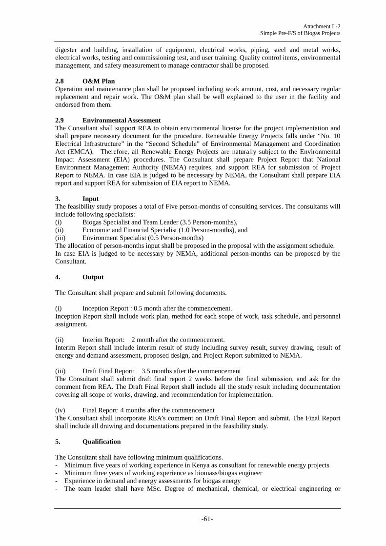
Attachment L-2 Simple Pre-F/S of Biogas Projects
-61-
digester and building, installation of equipment, electrical works, piping, steel and metal works, electrical works, testing and commissioning test, and user training. Quality control items, environmental management, and safety measurement to manage contractor shall be proposed. 2.8 O&M Plan Operation and maintenance plan shall be proposed including work amount, cost, and necessary regular replacement and repair work. The O&M plan shall be well explained to the user in the facility and endorsed from them. 2.9 Environmental Assessment The Consultant shall support REA to obtain environmental license for the project implementation and shall prepare necessary document for the procedure. Renewable Energy Projects falls under “No. 10 Electrical Infrastructure” in the “Second Schedule” of Environmental Management and Coordination Act (EMCA). Therefore, all Renewable Energy Projects are naturally subject to the Environmental Impact Assessment (EIA) procedures. The Consultant shall prepare Project Report that National Environment Management Authority (NEMA) requires, and support REA for submission of Project Report to NEMA. In case EIA is judged to be necessary by NEMA, the Consultant shall prepare EIA report and support REA for submission of EIA report to NEMA. 3. Input The feasibility study proposes a total of Five person-months of consulting services. The consultants will include following specialists: (i) Biogas Specialist and Team Leader (3.5 Person-months), (ii) Economic and Financial Specialist (1.0 Person-months), and (iii) Environment Specialist (0.5 Person-months) The allocation of person-months input shall be proposed in the proposal with the assignment schedule. In case EIA is judged to be necessary by NEMA, additional person-months can be proposed by the Consultant. 4. Output The Consultant shall prepare and submit following documents. (i) Inception Report : 0.5 month after the commencement. Inception Report shall include work plan, method for each scope of work, task schedule, and personnel assignment. (ii) Interim Report: 2 month after the commencement. Interim Report shall include interim result of study including survey result, survey drawing, result of energy and demand assessment, proposed design, and Project Report submitted to NEMA. (iii) Draft Final Report: 3.5 months after the commencement The Consultant shall submit draft final report 2 weeks before the final submission, and ask for the comment from REA. The Draft Final Report shall include all the study result including documentation covering all scope of works, drawing, and recommendation for implementation. (iv) Final Report: 4 months after the commencement The Consultant shall incorporate REA’s comment on Draft Final Report and submit. The Final Report shall include all drawing and documentations prepared in the feasibility study. 5. Qualification The Consultant shall have following minimum qualifications. - Minimum five years of working experience in Kenya as consultant for renewable energy projects - Minimum three years of working experience as biomass/biogas engineer - Experience in demand and energy assessments for biogas energy - The team leader shall have MSc. Degree of mechanical, chemical, or electrical engineering or

Attachment L-2 Simple Pre-F/S of Biogas Projects
-62-
environmental science - Fluency in oral and written English * The high-lighten parts need to be revised considering input and conditions.

Attachment L-2 Simple Pre-F/S of Biogas Projects
-63-
Annex-3 Drawing of Nyeri Biogas Project
Drawing No. N-01-1 Flow of Biogas System Option-1 Cooking Fuel Supply Only
Drawing No. N-01-2 Flow of Biogas System Option-2 with Generation System
Drawing No. N-02 Excavation Plan for Biogas Digester (32, 60 m3)
Drawing No. N-03-1 AKUT Fixed Dome Type Biogas Digester (32 m3) for Human Waste
Drawing No. N-03-2 AKUT Fixed Dome Type Biogas Digester (60 m3) for Cow Dung
Drawing No. N-04 Control Chamber and Water Trap
Drawing No. N-05 Reinforcement Plan and Digester Manhole

m3
Biogas
Gas meter
Gas Holder
liquid fertilizerCow dung&Water
Gas Filter(H2S Remover)
Digester
(for Tank)Water trap
Gas Valve
Cooking Stoves
Kitchen
Biogas
Sewer line to septic tank
Digester
Human waste from toilet sewer line
Cow Dung Digester
Human Waster Digester
m3
Gas meter
Gas Filter(H2S Remover)
(for Tank)Water trap
Manometerm3
Gas meter(for Stove)
Project for Establishment of
Using Renewable Energy in KenyaRural Electrification Model Conceptual Diagram of Biogas System
Ver. 14/10/14
For reference only. Drawing for work shall be prepared by the Contractor.
Flow of Biogas System Rural Electrification Authority
Date: 12/11/14Version: 0.1Scale: NTS Drawn by:
Checked by:Pre-feasibility Study of Biogas Project in Nyeri High School
Option-1 Cooking Fuel Supply Only
Drawing No.: N-01-1

Gas Valve
Cooking Stoves
Kitchen
Manometerm3
Gas meter(for Stove)
m3
Biogas
Gas meter
Gas Holder
liquid fertilizer
Cow dung&Water
Gas Filter(H2S Remover)
Digester
(for Tank)
Water trap
m3
Biogas
Gas meter
Sewer line to septic tank
Gas Filter(H2S Remover)
Digester
(for diester)
Water trap
Human waste from toilet sewer line
Cow Dung Digester
Human Waster Digester
Gas Holder
Gas Valve Energy
meterControl Chamber
Control Chamber
V
A
WhG
Lamp
Em3
Engine GeneratorGas meter(for Engine)
Air Inlet Valve
Power Supply
Wh
Grid
DistributionPanel Consumer UnitChangeover
Switch
MCB
Generation system
Internal load
Project for Establishment of
Using Renewable Energy in KenyaRural Electrification Model Conceptual Diagram of Biogas System
Ver. 14/10/14
For reference only. Drawing for work shall be prepared by the Contractor.
Flow of Biogas System Rural Electrification Authority
Date: 12/11/14Version: 0.1Scale: NTS Drawn by:
Checked by:Pre-feasibility Study of Biogas Project in Nyeri High School
Option-2 with Generation System
Drawing No.: N-01-2
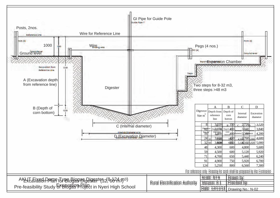
Ground level
Posts, 2nos.Wire for Reference Line
Wire Pegs (4 nos.)
Expansion Chamber
1000
A (Excavation depth from reference line)
B (Depth of corn bottom)
C (Internal diameter)
D (Excavation Diameter)
GI Pipe for Guide Pole
Digester Two steps for 8-32 m3, three steps >48 m3
A B C DDepth from
referenceline
Depth ofcorn
botton
Internaldiameter
Excavationdiameter
8 3,020 350 2,720 3,52012 3,170 400 3,040 3,84016 3,400 400 3,360 4,20024 3,650 450 3,760 4,60032 3,900 550 4,160 5,00048 4,300 600 4,800 5,60059 4,500 600 5,120 5,92071 4,700 650 5,440 6,24091 4,900 750 5,920 6,700
124 5,250 800 6,560 7,300
DigestorSize m3
For reference only. Drawing for work shall be prepared by the Contractor.
AKUT Fixed Dome Type Biogas Digester (8-124 m3) Rural Electrification Authority
Date: 12/11/14Version: 0.1Scale: NTS Drawn by:
Checked by:Excavation Plan
A B C DDepth from
referenceline
Depth ofcorn
botton
Internaldiameter
Excavationdiameter
32 3,900 550 4,160 5,00060 4,500 600 5,120 5,920
DigestorSize m3
For reference only. Drawing for work shall be prepared by the Contractor.
Excavation Plan for Biogas Digester (32, 60 m3) Rural Electrification Authority
Date: 12/11/14Version: 0.1Scale: NTS Drawn by:
Checked by:Pre-feasibility Study of Biogas Project in Nyeri High School Drawing No.: N-02

PVC pipe Φ4”
Feeding Chamber
For reference only. Drawing for work shall be prepared by the Contractor.
Reinforced concrete beam
Reinforced concrete
Gas pipe
Ring beam
Gas tight dome Slurry
Manholecover Expansion chamber (E.C.)
Feeding chamber (F.C.)
Enclosed digester
Overflow
PVC pipe Φ4”
25mm plaster for gas tight
Reinforced concrete
A B C D E F G H I J K L M N O P Q R SDigesterinternaldiameter
Corndepth
Digesterradius
Domeradius
Doemheight
Bottomslab
thickness
1st stepslab
thickness
2nd stepslab
thickness
1st stepslab width
1st stepslab height
2nd stepslab width
2nd stepslab height
E.C. slabthickness
E.C.internaldiameter
Ring beaminner sidethichness
Ring beamouter sidethichness
F.C. slabthickness
F.C.height
F.C.diameter
8 2,720 350 R1360 R1700 770 120 100 100 750 550 400 550 100 2,280 60 170 100 800 1,00012 3,040 400 R1520 R1900 820 120 100 100 750 600 400 500 100 2,720 60 170 100 800 1,00016 3,360 400 R1680 R2100 900 150 100 100 750 600 400 600 100 3,200 60 170 100 800 1,00024 3,760 450 R1880 R2350 1,000 150 100 100 750 650 400 650 100 3,800 60 170 100 800 1,00032 4,160 550 R2080 R2600 1,100 150 100 100 750 650 400 650 100 4,360 60 170 100 800 1,000
DigestorSize m3
DD DE DF DG DH DI DJ DK
Slurryoutlet
Manholering beambottom
E.C. slabbottom
Wall topedge
Ring beambottom
1st stepslab
bottom
Digesterslab
bottom
Digesterbottom
1,000 1,200 1,600 1,880 1,940 2,700 3,020 3,3701,000 1,150 1,600 1,910 1,970 2,070 3,170 3,6001,000 1,150 1,600 1,990 2,050 2,800 3,400 3,8001,000 1,150 1,600 2,090 2,150 2,900 3,650 4,1001,000 1,150 1,600 2,190 2,250 2,900 3,900 4,550
Dimension of Fixed Dome Digester (mm)
AKUT Fixed Dome Type Biogas Digester (8-32 m3) Rural Electrification Authority
Date: 12/11/14Version: 0.1Scale: NTS Drawn by:
Checked by:
A Digester internal diameter
C Digester radius
B Corn depth
D Dome radius
F Bottom slab t
O Ring beam inner side t
P Ring beam outer side t
E Dome height
G 1st step slab t
H 2nd step slab t
I 1st step w
J 1st step h
K 2nd step w
L 2nd step h
N E.C. nternal diameter
M E.C. slab t
Q F.C. slab t
R F.C. height
Reference line
Rest of neck DA DB
DJ
DI
DH DG
DF
DE DD DC
DK
Gas outlet pipeF.C. Slab Top
Slurry outlet
Manhole ringbeam bottom
E.C .Slab bottom
Wall top edge Ring beam bottom
1st step bottom
Digester slab bottom
Digester bottom
0.00Depth S F.C. diameter
t: thicknessh: heightw: width
A B C D E F G H I J K L M N O P Q R SDigesterinternaldiameter
Corndepth
Digesterradius
Domeradius
Doemheight
Bottomslab
thickness
1st stepslab
thickness
2nd stepslab
thickness
1st stepslab width
1st stepslab height
2nd stepslab width
2nd stepslab height
E.C. slabthickness
E.C.internaldiameter
Ring beaminner sidethichness
Ring beamouter sidethichness
F.C. slabthickness
F.C.height
F.C.diameter
32 4,160 550 R2080 R2600 1,100 150 100 100 750 650 400 650 100 4,360 60 170 100 800 1,000
DigestorSize m3
Dimension of Fixed Dome Digester (mm)
DA DB DC DD DE DF DG DH DI DJ DK
Rest ofneck
Gas outletpipe
F.C. slabtop
Slurryoutlet
Manholering beam
bottom
E.C. slabbottom
Wall topedge
Ring beambottom
1st stepslab
bottom
Digesterslab
bottom
Digesterbottom
32 550 650 900 1,000 1,150 1,600 2,190 2,250 2,900 3,900 4,550
DigestorSize m3
AKUT Fixed Dome Type Biogas Digester (32 m3) for Cow DungPre-Feasibility Study of Biogas Project in Nyeri High School
Rural Electrification Authority
Date: 12/11/14Version: 0.1Scale: NTS Drawn by:
Checked by:Drawing No.: N03-1

PVC pipe Φ4”
Feeding Chamber
Reinforced concrete beam
Reinforced concrete
Gas pipe
Ring beam
Gas tight dome Slurry
Manholecover Expansion chamber (E.C.)
Feeding chamber (F.C.)
Enclosed digester
Overflow
PVC pipe Φ4”
25mm plaster for gas tight
For reference only. Drawing for work shall be prepared by the Contractor.
Reinforced concreteA Digester internal diameter
C Digester radius
B Corn depth
D Dome radius
F Bottom slab t
O Ring beam inner side t
P Ring beam outer side t
E Dome height
G 1st step slab t
H 2nd step slab t
I 1st step wJ 1st step h
K 2nd step w
L 2nd step h
N E.C. nternal diameter
M E.C. slab t
Q F.C. slab t
R F.C. height
Reference line
Rest of neck DA DB
DJ
DI
DH DG
DF
DE DD DC
DK
Gas outlet pipeF.C. Slab Top
Slurry outlet
Manhole ringbeam bottom
E.C .Slab bottom
Wall top edge
Ring beam bottom
1st step top
Digester slab bottom
Digester bottom
0.00Depth S F.C. diameter
t: thicknessh: heightw: width
H’ 3rd step slab t
L’ 3rd step hK’ 3rd step w
G’ Middle Beam t DI’Middle beam
bottom
Dimension of Fixed Dome Digester (mm)
AKUT Fixed Dome Type Biogas Digester (48-124 m3) Rural Electrification AuthorityDate: 12/11/14Version: 0.1Scale: NTS Drawn by:
Checked by:
DA DB DC DD DE DF DG DH DI DI' DJ DKRest of
neckGas outlet
pipeF.C. slab
topSlurryoutlet
Manholering beam
bottom
E.C. slabbottom
Wall topedge
Ring beambottom
1st stepslab top
Middlebeam
bottom
Digesterslab
bottom
Digesterbottom
48 550 650 900 1,000 1,150 1,600 2,350 2,440 3,340 3,490 4,300 4,90059 550 650 900 1,000 1,150 1,600 2,430 2,520 3,360 3,490 4,500 5,25071 550 650 900 1,000 1,150 1,600 2,510 2,630 3,510 3,670 4,700 5,35091 550 650 900 1,000 1,150 1,600 2,530 2,650 3,730 3,880 4,900 5,650
124 550 650 900 1,000 1,150 1,600 2,640 2,760 4,060 4,240 5,250 6,050
DigestorSize m3
A B C D E F G G' H H' I J K K' L L' M N O P Q R SDigesterinternaldiameter
Corndepth
Digesterradius
Domeradius
Domeheight
Bottomslab
thickness
1st stepslab
thickness
Middlebeam
thickness
2nd stepslab
thickness
3rd stepslab
thickness
1st stepslab width
1st stepslab height
2nd stepslab width
3rd stepslab width
2nd stepslab height
3rd stepslab height
E.C. slabthickness
E.C.internaldiameter
Ring beaminner sidethichness
Ring beamouter sidethichness
F.C. slabthickness
F.C.height
F.C.diameter
48 4,800 600 R2400 R3000 1,050 150 120 150 120 100 750 610 400 400 610 620 100 4,600 90 200 100 800 1,10060 5,120 600 R2560 R3200 1,280 150 120 130 120 100 750 620 400 400 620 620 100 5,260 90 200 100 800 1,10071 5,440 650 R2720 R3400 1,360 150 100 160 100 100 700 670 400 400 670 670 100 5,560 120 230 100 800 1,20091 5,920 750 R2960 R3700 1,480 150 100 150 100 100 700 730 400 400 750 750 100 6,260 120 230 100 800 1,200
124 6,560 800 R3280 R4100 1,640 150 100 180 100 100 600 850 400 400 850 850 100 7,040 120 230 100 800 1,200
DigestorSize m3
Drawing No.: G03-2
Dimension of Fixed Dome Digester (mm)
AKUT Fixed Dome Type Biogas Digester (60 m3) for Cow DungRural Electrification Authority
Pre-Feasibility Study of Biogas Project in Nyeri High School Date: 12/11/14Version: 0.1Scale: NTS Drawn by:
Checked by:Drawing No.: N03-2
A B C D E F G G' H H' I J K K' L L' M N O P Q R SDigesterinternaldiameter
Corndepth
Digesterradius
Domeradius
Domeheight
Bottomslab
thickness
1st stepslab
thickness
Middlebeam
thickness
2nd stepslab
thickness
3rd stepslab
thickness
1st stepslab width
1st stepslab height
2nd stepslab width
3rd stepslab width
2nd stepslab height
3rd stepslab height
E.C. slabthickness
E.C.internaldiameter
Ring beaminner sidethichness
Ring beamouter sidethichness
F.C. slabthickness
F.C.height
F.C.diameter
60 5,120 600 R2560 R3200 1,280 150 120 130 120 100 750 620 400 400 620 620 100 5,260 90 200 100 800 1,100
DigestorSize m3
DA DB DC DD DE DF DG DH DI DI' DJ DKRest of
neckGas outlet
pipeF.C. slab
topSlurryoutlet
Manholering beam
bottom
E.C. slabbottom
Wall topedge
Ring beambottom
1st stepslab top
Middlebeam
bottom
Digesterslab
bottom
Digesterbottom
60 550 650 900 1,000 1,150 1,600 2,430 2,520 3,360 3,490 4,500 5,250
DigestorSize m3
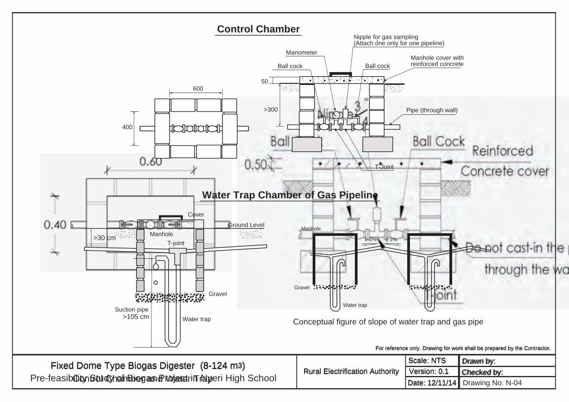
For reference only. Drawing for work shall be prepared by the Contractor.
Fixed Dome Type Biogas Digester (8-124 m3) Rural Electrification Authority
Date: 12/11/14Version: 0.1Scale: NTS Drawn by:
Checked by:Control Chamber and Water Trap
Gravel
Water trap>105 cm
T-joint
Suction pipe
Manhole
Cover
Ground Level
>30 cm 1-2%
Gravel
Manhole
Water trap
1-2%
Control Chamber
Water Trap Chamber of Gas Pipeline
Conceptual figure of slope of water trap and gas pipe
400
60050
>300
T-Joint
Pipe (through wall)
Manhole cover with reinforced concreteBall cockBall cock
Manometer
Nipple for gas sampling(Attach one only for one pipeline)
Pre-feasibility Study of Biogas Project in Nyeri High School
For reference only. Drawing for work shall be prepared by the Contractor.
Fixed Dome Type Biogas Digester (8-124 m3) Rural Electrification Authority
Date: 12/11/14Version: 0.1Scale: NTS Drawn by:
Checked by:Drawing No: N-04

Beam Reinforcements Ring beam Middle beam Base beamManhole
Manhole Cover
Gas pipe Manhole ring beam
Manhole cover
25mm plaster for gas tight
Digester Manhole
AB
Stirrup c/c C
Nominal size D
Nominal size EAB
AB
CED
Stirrup c/c F
Nominal size G
Nominal size H
CD
Stirrup c/c E
Nominal size F
Nominal size GAB
CD
Stirrup c/c E
Nominal size F
Nominal size GAB
400
Φ760
400
4 nos. of handles, R8
Concretet=180 mm
Cement mortar
Clay180
Φ1100
Φ800
A B C D ESteel barwidth/height
Beamwidth/height
Stirrup C/Cmm
Barnominal
size
Barnominal
size
8 100 150 c/c 200 R6 R812 100 150 c/c 200 R6 R816 100 150 c/c 200 R6 R824 100 150 c/c 200 R6 R832 100 150 c/c 200 R6 R848 100 150 c/c 200 R6 R860 100 150 c/c 200 R6 R871 100 150 c/c 200 R6 R891 100 150 c/c 200 R6 R8
124 100 150 c/c 200 R6 R8
DigestorSize m3
A B C D E F G HSteel bar
widthBeamwidth
Beamheightsmall
Steel barheight
Beamheightlarge
StirrupC/C mm
Barnominal
size
Barnominal
size
8 100 150 60 100 170 c/c 300 R6 R812 100 150 60 100 170 c/c 300 R6 R816 100 150 60 100 170 c/c 300 R6 R824 100 150 60 100 170 c/c 300 R6 R832 100 150 60 100 170 c/c 300 R6 R848 100 150 90 100 200 c/c 300 R6 R860 100 150 90 100 200 c/c 300 R6 R871 100 150 120 100 230 c/c 300 R6 R891 100 150 120 230 c/c 300 R6 R8
124 100 150 120 100 230 c/c 300 R6 R8
DigestorSize m3
A B C D E F GSteel bar
widthBeamwidth
Steel barheight
Beamheight
StirrupC/C mm
Barnominal
size
Barnominal
size
8 - - - - - - -12 - - - - - - -16 - - - - - - -24 - - - - - - -32 - - - - - - -48 100 150 100 150 c/c 300 R6 R860 100 150 100 130 c/c 300 R6 R871 100 150 100 160 c/c 300 R6 R891 100 150 100 150 c/c 300 R6 R8
124 100 150 120 180 c/c 300 R6 R8
DigestorSize m3
A B C D E F GSteel bar
widthBeamwidth
Steel barheight
Beamheight
StirrupC/C mm
Barnominal
size
Barnominal
size
8 100 200 80 120 c/c 300 R6 R812 100 200 80 120 c/c 300 R6 R816 100 250 100 150 c/c 300 R6 R824 100 250 100 150 c/c 300 R6 R832 100 250 100 150 c/c 300 R6 R848 100 250 100 150 c/c 300 R6 R860 100 250 100 150 c/c 300 R6 R871 150 250 100 150 c/c 300 R6 R891 150 250 100 150 c/c 300 R6 R8
124 150 250 100 150 c/c 300 R6 R8
DigestorSize m3
For reference only. Drawing for work shall be prepared by the Contractor.
AKUT Fixed Dome Type Biogas Digester (8-124 m3) Rural Electrification Authority
Date: 12/11/14Version: 0.1Scale: NTS Drawn by:
Checked by:Reinforcement Plan and Digester Manhole
A B C D ESteel barwidth/height
Beamwidth/height
Stirrup C/Cmm
Barnominal
size
Barnominal
size
32 100 150 c/c 200 R6 R860 100 150 c/c 200 R6 R8
DigestorSize m3
A B C D E F G HSteel bar
widthBeamwidth
Beamheightsmall
Steel barheight
Beamheightlarge
StirrupC/C mm
Barnominal
size
Barnominal
size
32 100 150 60 100 170 c/c 300 R6 R860 100 150 90 100 200 c/c 300 R6 R8
DigestorSize m3
A B C D E F GSteel bar
widthBeamwidth
Steel barheight
Beamheight
StirrupC/C mm
Barnominal
size
Barnominal
size
32 - - - - - - -60 100 150 100 130 c/c 300 R6 R8
DigestorSize m3
A B C D E F GSteel bar
widthBeamwidth
Steel barheight
Beamheight
StirrupC/C mm
Barnominal
size
Barnominal
size
32 100 250 100 150 c/c 300 R6 R860 100 250 100 150 c/c 300 R6 R8
DigestorSize m3
For reference only. Drawing for work shall be prepared by the Contractor.
Reinforcement Plans for Biogas Digester (32, 60 m3) Rural Electrification Authority
Date: 12/11/14Version: 0.1Scale: NTS Drawn by:
Checked by:Pre-feasibility Study of Biogas Project in Nyeri High School Drawing No.: N-05

Project for Establishment of Rural Electrification Model using Renewable Energy
Seminar on Biogas Planning and Design
bybyCaroline Kelly
125/10/2013 1
ContentsContents1. Basics and Characteristics of Biogasg2. REA Biogas System Model3 Lessons learned from Past Biogas Projects3. Lessons learned from Past Biogas Projects4. Site Survey5. Basic Plan and Pre-F/S
1. Energy Production and Demand Assessment2. Benefit Assessment3. Basic Design4. Cost Estimation5. Economic/Financial Evaluation
2
1. Basics of Biogas: as renewable energy1. Basics of Biogas: as renewable energyBiogas:
Fuel gas produced by anaerobic fermentation of organicFuel gas produced by anaerobic fermentation of organic material by methane producing bacteria Generally 50-60% methane is containedGenerally, 50 60% methane is contained.
Major gas component is methane (CH4), CO2, and H2O, Minor gas component is H2, N2, H2S2 2 2
Biogas can be used as cooking fuel and generationCarbon neutral.
Type kcal/kg MJ/m3 Mol massType kcal/kg MJ/m3 Mol-massH2 33,886 10.8 2CO 2,414 10.8 28
3
,CH4 13,267 35.9 16C3H8 12,034 93.2 44
Basics of Methane FermentationBasics of Methane Fermentation
4

Characteristics of BiogasCharacteristics of BiogasAvailability of Feedstock is the prerequisite.a ab y o eeds oc s e p e equ s e
Plan and design should be done according to availability of feedstock Collection from otheravailability of feedstock. Collection from other place is not recommended.Cow dung is collective inherently containsCow dung is collective, inherently contains methano bacteria, and the best feedstock.
ApplicationDesign should be conducted so that O&M should gbe minimized.System should be as simple as possibleSystem should be as simple as possible.
5
P t Bi P j t i KPast Biogas Projects in KenyaOver 6 000 biogas installation for cooking fuel inOver 6,000 biogas installation for cooking fuel in household. 10,000 is planned by 2015.Bi i jBiogas generation projects
Kilifi (150 kW) sisal plantation, 2007Nyongara (9 kW) slaughter house by KIRDI and GIZ, 2010Mangu High School by REA (20 kVA), 2011Thika (55 kW) and Insinya (100 kW) flower farm, 2013Experience of biogas generation is not many
6
Establishment of Biogas System ModelEstablishment of Biogas System ModelFacility such as school with established ac y suc as sc oo es ab s edsewer system or modification of pit latrine Ad antageAdvantage
Human waste is collective with septic tankGenerally owns cows for milk supply. Cow dung is best source of biogas.g g
ChallengesP t f h t iProper management of human waste is necessary (prevention of detergent, sanitary
t t t t t )waste, water content, etc)7
REA Biogas SystemREA Biogas System
Biogas digesterRed text: installed by theproject
Toilet of Schooldormitory
S i k
BiogasGenerator
Septic tank
GasBag
Cowshedk
EffluentDung
BiogasdigesterCooking stoveField
Feed
8

Lessons learned from past biogas projects 1Lessons learned from past biogas projects 1Design component
The long length of the piping should be avoided, to minimize pressure loss and leakage.Channeling difference of elevation to transport the material by gravity is necessary for cow dung effluent transport.
Digester connected from toilet The effluent from toilet digesters may contain helminth eggs or coliform It canThe effluent from toilet digesters may contain helminth eggs or coliform. It can be utilized as fertilizer only when adequate care is taken.The quantity of water used to flush the toilets should be limited (about 1L/person) This should be well explained to users1L/person). This should be well explained to users.Detergents with Chlorine should not be used for cleaning the toilets. Only biodegradable detergents should be used for cleaning purposes. O t il t hi h i t t d t th di t h ld b i d tOne toilet which is not connected to the digesters should be assigned to students taking medication to prevent antibiotics from entering the digester. For girls’ school, management of disposal of sanitary towels is necessary to
t h t f t i th di tprevent such waste from entering the digester.
9
Lessons learned from past biogas projects 2Lessons learned from past biogas projects 2Construction Supervision
It is necessary to include provision of user training manual andIt is necessary to include provision of user training, manual and drawings, and testing and commissioning in the contract with a contractor. Full-time supervision for approval of construction quality and documentation is necessary. Exclusive staff for supervision should be assigned.assigned.It is necessary to check the leakage of gas throughout pipe line and gas bag. Checking of the pipe route is necessary.
User O&MProhibition of potential fire hazards should be strictly appliedUser participation from the stage of planning and constructionUser participation from the stage of planning and construction supervision is necessary as well as training for O&M. Use of cow dung as feedstock in addition to human waste is recommended for favorable bacteria for biogas generation.
10
Project Flow for Biogas GenerationProject Flow for Biogas GenerationPreliminary information collection
Conducting site survey
Feedstock is
Procedure for environmental clearance
No Feedstock is available? Tender process
Yes
ssib
le
No
User is willing to conduct?
Contract
Construction supervisionYes not
pos No
Preparation of basic planning and F/S
p
User training
Yes
Proj
ect
Feasible? Operation and maintenance
Yes
No
11
Design and preparation of specification Evaluation
3.1 Preparation of Site Survey3.1 Preparation of Site SurveyInformation collection of facility list from Ministries and local governmentlocal governmentConfirmation of location and road condition on the map usingg
Using google map/earth and identifying coordinate (latitude and longitude) makes the survey easier.
Appointment for facility managerAppointment with technician or staff who manages cows and toilet is preferredtoilet is preferred.
Preliminary introduction and interview about the willingness of the project over the phonewillingness of the project over the phoneTools to bring: digital camera, GPS, measuring tape, sketch book, interview sheet, distance meter, booklet about biogas
12
Sit S It (1)Site Survey Items (1)Location
Facility name, address, coordinate, elevation, map etc.
InfrastructureSurrounding road condition, distance from Nairobi, power supply condition, water supply condition
Facility dataFacility dataFinanced by, organization structure, establishment year, name and contact of manager and key staff, geological structure, operation hours, etc.
Possible amount of feedstockN f i lt f t d t t f t i lNos of cows, pigs, poultry, nos of student, qty of raw materials, frequency of toilet use etc.
Possible location of systemPossible location of systemDigester, generation system, pipe layout, effluent supply, etc.
13
Site Survey Items (2)Site Survey Items (2) Facility layout
Layout of facility, sketch or map of buildings inside the facility, y y, p g y,location of toilet & septic tank, cow/pig/poultry shed, kitchen, etc.
Usage of effluentLocation of garden, area of garden and type of vegetable
Current usage of energy (demand analysis)Availability of diesel engine and condition of usageConsumption and cost of fuel wood, electricity, LPG gas, diesel oil, electricity tariff, etc.e ect c ty ta , etcCurrent electric appliance, type of lighting
Priority of biogas usageElectricity, cooking fuel, lamp
PhotosCow shed, garden, toilet, location for digester, etc.
14
Teacher'sQtr (22)UnpavedRoad
Example Class Rooms (17)pof Sketch Admin. Block
Lab. andLibrary
CharchSocialHall
Library
D/G
DormDining
Dorm
Dorm Dorm Dorm Dorm Dorm Dorm
Dorm Dorm Dorm Dorm Dorm DormDorm Dorm Dorm Dorm Dorm Dorm
KitchenToilet
SepticTank
Cowshed
Cow shed Proposeddigesterslocation
0 100 m
15
Indicate direction and scale.
Indicate main facirities such as class rooms, toilets, stores, cow shed, and kitchen considering demension.
SchoolFarmFish Pond
0 00
User’s InvolvementUser s InvolvementF th ti f d t il d l ti t h lFrom the time of survey, detailed explanation to school manager and commitment of cooperation for project implementation is necessary for:implementation is necessary for:
Assignment of a project manager responsible for overall project implementationParticipation in preparation of planningConducting construction supervisionUndertaking of user training from contractorUndertaking of user training from contractorHiring staff and conducting Operation and maintenanceMonitoring, recording, data provision for evaluationo to g, eco d g, data p o s o o e a uat o
16

Basic Plan: Items required forBasic Plan: Items required for project preparation1. Outline and Purpose (from site survey)2 Particular Features of site (from site survey)2. Particular Features of site (from site survey)3. Energy Production and Demand Assessment
B fit A t4. Benefit Assessment5. Basic Design6. Cost Estimation7. Economic/Financial Evaluation7. Economic/Financial Evaluation
17
Energy Production and Demand Assessment:gyAmount of biogas production -- Livestock
Type of feedstock 3 /k 1) k / 2)Type of feedstock m kg ) kg/nos )
Cattle (cows and bullocks) 0.023-0.04 16-24Pig 0 04-0 059 1 9-2 5Pig 0.04-0.059 1.9-2.5Poultry 0.065-0.116 0.075-0.11) Biogas as an alternative to fuelwood for a household in Uleppi sub-country in Uganda
C id ti i f d i ht f li t k t
2) http://ishikawa.lin.gr.jp/kankyo/02.htm
Example:
Consideration is necessary for average age and weight of livestock to determine possible amount of gas production. (ex. 16kg/nos for young cattle)
Example:15 cows: 15 nos x 20 kg/nos x 0.033 m3/kg= 9.9 m3
100 pigs: 100 nos x 2.0 kg/nos x 0.05 m3/kg = 10 m3
18
Energy production and demand gy pAmount of biogas production-- Human
Description Value UnitAmount of biogas production 0.02-0.04 m3/person/daySize of digester 0.1 m3/person/dayg p ySubstrate 3.3-4.9 L/person/day faeces 0.25-0.4 kg/person/day
urine 1-1 5 L/person/day
Availability ratio needs to be considered according to actual condition.
urine 1 1.5 L/person/day flushing water 2-3 L/person/day
750 students: 750 nos x 0.025 m3/nos/day x 0.8 x 0.67 = 10.1 m3 /day0.8: Body weight ratio, student / adult0.67: Dormitory toilet usage ratio (evening and morning)y g ( g g)
It is recommended to add cow dung to supply methane producing bacteria. School available days ratio (without holiday) 0.75 needs to be considered for annual
19
y ( y)estimation.
Calorific Value and Generation EnergyCalorific Value and Generation Energy
1 J = 1 kg·m²/s² = 1 Ws (Watt-second) = 0.239 Cal
1Wh = 3600 Ws = 3600 J = 860 Cal
J Wh Cal1 J 1 = 0 278×10 3 0 2391 J 1 = 0.278×10 0.239
1 Wh = 3600 1 8601Cal = 4.1868 = 1 163×10 3 11Cal 4.1868 1.163 10 1
1MJ =0.278 kWh
20
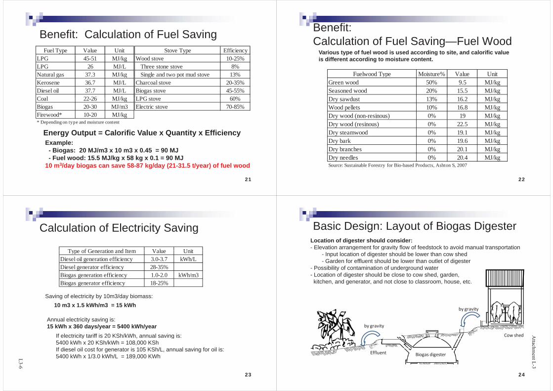
Benefit: Calculation of Fuel SavingBenefit: Calculation of Fuel SavingFuel Type Value Unit Stove Type Efficiency
LPG 45-51 MJ/kgLPG 26 MJ/LNatural gas 37.3 MJ/kg
Wood stove 10-25% Three stone stove 8%
Single and two pot mud stove 13%Natu a gas 37.3 J/ gKerosene 36.7 MJ/LDiesel oil 37.7 MJ/LCoal 22 26 MJ/kg
S g e a d two pot ud stove 3%Charcoal stove 20-35%Biogas stove 45-55%LPG stove 60%Coal 22-26 MJ/kg
Biogas 20-30 MJ/m3Firewood* 10-20 MJ/kg
LPG stove 60%Electric stove 70-85%
* Depending on type and moisture content
Energy Output = Calorific Value x Quantity x Efficiency E lExample:- Biogas: 20 MJ/m3 x 10 m3 x 0.45 = 90 MJ- Fuel wood: 15.5 MJ/kg x 58 kg x 0.1 = 90 MJ
21
10 m3/day biogas can save 58-87 kg/day (21-31.5 t/year) of fuel wood
Benefit: Calculation of Fuel Saving—Fuel Wood
Various type of fuel wood is used according to site, and calorific value
Fuelwood Type Moisture% Value Unit
yp g ,is different according to moisture content.
ypGreen wood 50% 9.5 MJ/kgSeasoned wood 20% 15.5 MJ/kgD d t 13% 16 2 MJ/kDry sawdust 13% 16.2 MJ/kgWood pellets 10% 16.8 MJ/kgDry wood (non-resinous) 0% 19 MJ/kgDry wood (resinous) 0% 22.5 MJ/kgDry steamwood 0% 19.1 MJ/kgDry bark 0% 19 6 MJ/kgDry bark 0% 19.6 MJ/kgDry branches 0% 20.1 MJ/kgDry needles 0% 20.4 MJ/kg
22
Source: Sustainable Forestry for Bio-based Products, Ashton S, 2007
Calculation of Electricity SavingCalculation of Electricity Saving
Type of Generation and Item Value UnitType of Generation and Item Value UnitDiesel oil generation efficiency 3.0-3.7 kWh/LDiesel generator efficiency 28-35%Biogas generation efficiency 1.0-2.0 kWh/m3Biogas generator efficiency 18-25%
10 m3 x 1.5 kWh/m3 = 15 kWhSaving of electricity by 10m3/day biomass:
Annual electricity saving is: 15 kWh x 360 days/year = 5400 kWh/year
If electricity tariff is 20 KSh/kWh annual saving is:If electricity tariff is 20 KSh/kWh, annual saving is: 5400 kWh x 20 KSh/kWh = 108,000 KShIf diesel oil cost for generator is 105 KSh/L, annual saving for oil is:5400 kWh x 1/3 0 kWh/L = 189 000 KWh
23
5400 kWh x 1/3.0 kWh/L 189,000 KWh
Basic Design: Layout of Biogas DigesterBasic Design: Layout of Biogas DigesterLocation of digester should consider:- Elevation arrangement for gravity flow of feedstock to avoid manual transportationg g y
- Input location of digester should be lower than cow shed- Garden for effluent should be lower than outlet of digester
- Possibility of contamination of underground water- Location of digester should be close to cow shed, garden, kitchen, and generator, and not close to classroom, house, etc.
by gravity
by gravity
Cow shedCow shed
Biogas digesterEffluent
24

Design of Biogas SystemDesign of Biogas System
Determination of digester volumeDetermination of digester typeStrength of digesterStrength of digesterSelection of pipe (for liquid ,gas)Selection of generator
25
Determination of Digester SizeDetermination of Digester Size120
140
100
120
y = 1.8856x80
100
erSize
m3
y = 0.1x
60
80
100
erSize
m3
20
40
60
Digeste
20
40Digeste
0
Nosof Cow
0
Nosof person
It is recommended to select one larger size
Nosof Cowand DigesterSize Nosof Person for Toiletand
Maximum size is 100m3, considering structural strength
Cow dung: Size (m3) = 1.89 x nos of CowHuman waste: Size (m3) = 0 1 x nos of person utilizing toilet
26
Human waste: Size (m ) = 0.1 x nos of person utilizing toilet
Types of Biogas digesterTypes of Biogas digesterFixed dome type
Mainly developed in China, 5-100 m3y pConstruction requires great care in design and workmanshipLong life time (30 years) and life-time cost is cheaper than floating drum type
Floating drum typeFloating drum typeMainly build in India, 5-100 m3
easy to understand and operategas at a constant pressure, and the stored gas-volume is recognizable by the position of the drum.The steel drum is expensive and maintenance-intensive. Removing rust andThe steel drum is expensive and maintenance intensive. Removing rust and painting has to be carried out regularly. The life-time of the drum is short (5-15 years)
Gas Bag typeGas Bag typeSmall and household type (3-10 m3)Cheap, short installation time, excavation and construction not requiredLife time is short (10-15 years), durability depends on material.
27
Gas Bag Typeg yp
FloatingDrum TypeDrum Type
FixedDorm Typeyp
Fixed Dorm Type is l d f i i iselected for institution
biogas type
282014/12/17Nippon Koei Co., Ltd
Source of drawing: Biogas processes for sustainable development, FAO, 1992
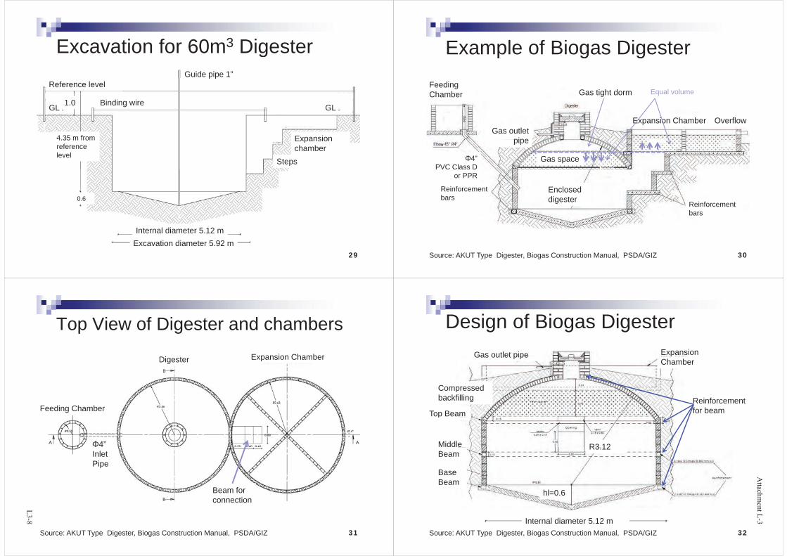
Excavation for 60m3 DigesterGuide pipe 1”
Excavation for 60m Digesterp p
Binding wire
Reference level
GLGL 1.0
Expansion
GL .
4 35 m from
GL .
Expansion chamber
Steps
4.35 m from reference level
0.6
Internal diameter 5 12 m
0.6
Internal diameter 5.12 m
29Excavation diameter 5.92 m
Example of Biogas DigesterExample of Biogas Digester
Feeding Chamber Gas tight dorm Equal volume
OverflowExpansion ChamberGas outlet
pipe
Gas space4”PVC Class D
pipe
Enclosed digester
Reinforcement bars
or PPR
digester Reinforcement bars
30Source: AKUT Type Digester, Biogas Construction Manual, PSDA/GIZ
Top View of Digester and chambersTop View of Digester and chambersExpansion ChamberDigester Expansion Chamber
Feeding Chamber
4” Inlet Pipe
Beam for connection
31Source: AKUT Type Digester, Biogas Construction Manual, PSDA/GIZ
Design of Biogas DigesterDesign of Biogas DigesterExpansion Gas outlet pipe pChamber
Gas outlet pipe
CompressedCompressed backfilling
Top BeamReinforcementfor beamp
Middle R3 12Beam
Base
R3.12
Beamhl=0.6
32Internal diameter 5.12 m
Source: AKUT Type Digester, Biogas Construction Manual, PSDA/GIZ
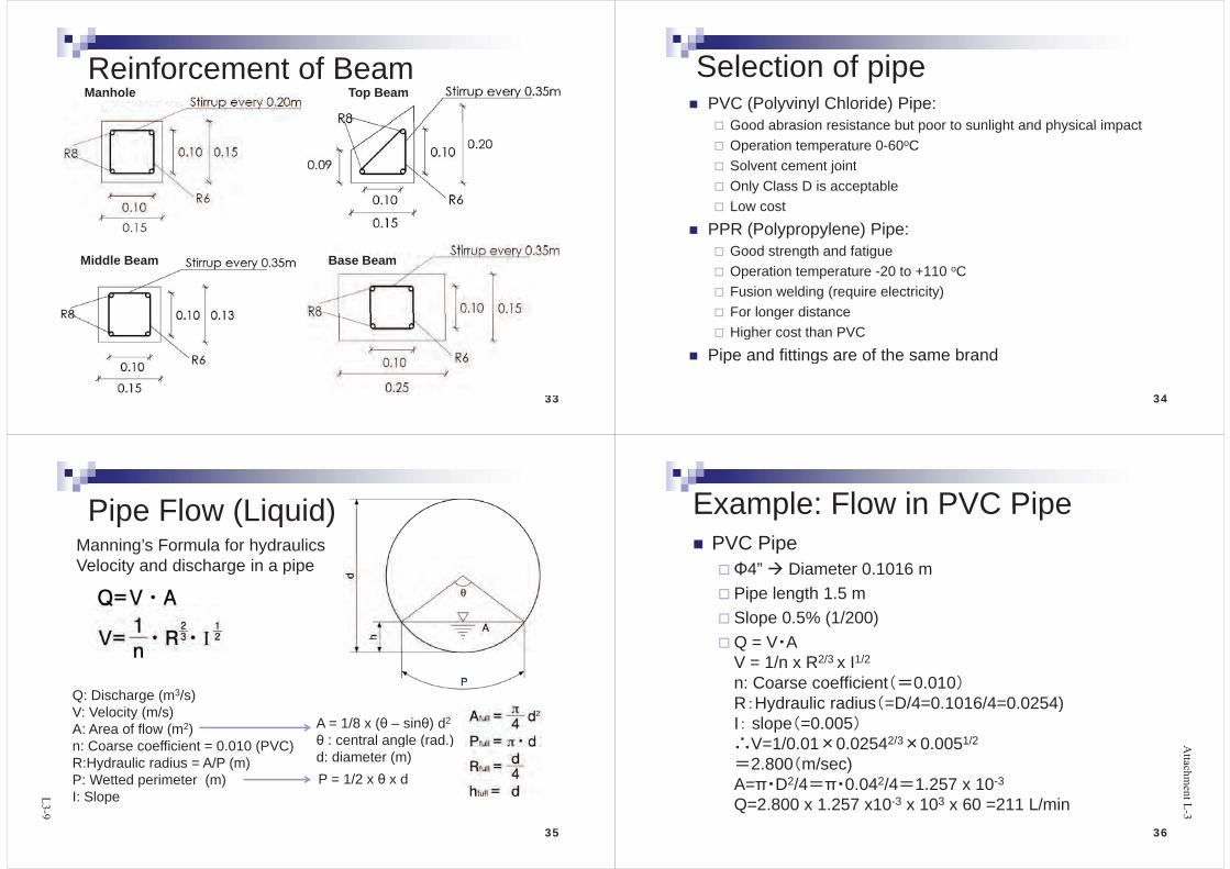
Reinforcement of BeamReinforcement of BeamManhole Top Beam
Middle Beam Base Beam
33
Selection of pipeSelection of pipePVC (Polyvinyl Chloride) Pipe:
Good abrasion resistance but poor to sunlight and physical impactGood abrasion resistance but poor to sunlight and physical impactOperation temperature 0-60oCSolvent cement jointSolvent cement jointOnly Class D is acceptableLow cost
PPR (Polypropylene) Pipe:Good strength and fatigueOperation temperature -20 to +110 oC Fusion welding (require electricity)For longer distanceFor longer distanceHigher cost than PVC
Pipe and fittings are of the same brandPipe and fittings are of the same brand
34
Pipe Flow (Liquid)Pipe Flow (Liquid)Manning’s Formula for hydraulicsVelocity and discharge in a pipe
Q: Discharge (m3/s)Q: Discharge (m /s)V: Velocity (m/s)A: Area of flow (m2)n: Coarse coefficient = 0 010 (PVC)
A = 1/8 x ( – sin ) d2
: central angle (rad.)n: Coarse coefficient = 0.010 (PVC)R:Hydraulic radius = A/P (m)P: Wetted perimeter (m)I: Slope
g ( )d: diameter (m)P = 1/2 x x d
35
I: Slope
Example: Flow in PVC PipeExample: Flow in PVC PipePVC Pipe
4” Diameter 0.1016 mPipe length 1.5 mSlope 0.5% (1/200)Q = V AV = 1/n x R2/3 x I1/2
n: Coarse coefficient 0.010R H d li di D/4 0 1016/4 0 0254)R Hydraulic radius =D/4=0.1016/4=0.0254)I slope =0.005
V=1/0 01 0 02542/3 0 0051/2V 1/0.01 0.0254 0.0052.800 m/sec)
A= D2/4 0.042/4 1.257 x 10⁻³
Q=2.800 x 1.257 x10-3 x 103 x 60 =211 L/min36

Pipe Diameter Selection for GasPipe Diameter Selection for Gas20 60 100 150
Length (m)Flow rate(m3/h)
PVC Pipe Diameter
0.5 0.5" 0.5" 0.5" 1"1 0.5" 0.5" 0.5" 1"
1.5 0.5" 0.5" 0.5" 1"2 0.75" 0.75" 0.75" 1"
2.5 1" 1" 1" 1.5"3 1 5" 1 5" 1 5" 1 5"3 1.5 1.5 1.5 1.54 1.5" 1.5" 1.5" 2.0"
Flow rate Length (m)
PPR Pipe Diameter
20 100 150 200 250 300 400 5000.5 25 25 25 25 25 25 32 321 25 25 25 32 32 32 32 40
(m3/h)
1 25 25 25 32 32 32 32 401.5 25 25 32 32 32 32 40 402 32 32 40 40 50 50 50 50
2 5 32 32 40 50 50 50 50 60
372014/12/17Nippon Koei Co., Ltd
2.5 32 32 40 50 50 50 50 603 32 32 50 50 50 50 60 604 32 40 50 50 50 60 60 60
Water trap for gasWater trap for gasWater is by-product of bi W tbiogas. Water vapour will condense in piping. Automatic water trap (U-p (shaped siphon) has to be installed.All gas pipes are laid inAll gas pipes are laid in a slope 1-2% (1-2 cm per 1m) towards the
t twater traps.
38
Pressure test unitPressure test unitControl chamber has to be constructed as pressure test unit Cl t th di t b tClose to the digester but outside the dome radius area.
39
Biogas engine/generatorBiogas engine/generatorGasoline engine generator
0.5-3 kWDiesel engine generator
Larger size > 10s kWgAvailable in marketModification is required for plugModification is required for plug
Biogas generatorSpecially arranged generator for biogas characteristicsSpecially arranged generator for biogas characteristicsFiltering unit is equippedSpecial order/import requiredSpecial order/import required
40

Cost EstimationCost EstimationThe estimated price is used for budgeting and reference price for tender evaluationCost components
Equipment, construction, labor, design, admin., operation and maintenance, renewal, etc.
Refer to past tender price (Pre F/S level)Refer to past tender price (Pre-F/S level)Need to reflect inflation rate
Quantify material and multiplying unit price (F/S level)Quantify material and multiplying unit price (F/S level)Requesting estimation to supplier
Estimation from each componentEstimation from each componentObtaining from possible contractor need to be careful since it nay against fairness of tendering
41
Estimation from past exampleEstimation from past example(Experimental)( p )1) Biogas digester (30-100m3):
y = 2,617 x + 256,700,,where y: cost (KSh), x: digester volume (m3)
2) Excavation works: 2,052 KSh/m3
3) Biogas bag: 20 550 KSh/m33) Biogas bag: 20,550 KSh/m4) Biogas generator: y=20,000x +100,000
, where y: cost (KSh), x: capacity of engine-generator (kVA)
42
Item
Qty unit KSh
Nyeri High School
Cost Estimation
Biogas Digester for Toilet 60 m3 413,720Biogas Digeter for Cow Shed 32 m3 340,444Excavation and civil works 1 lot 188,830
Estimation(Example,
Additional toilet facility with septic tankGas holding steel tank and connection valve 2 nos 100,800Bigoas flow meter 2 nos 73,000PVC b 1 411 000
( ppast tenderwas referred)
PVC gas bag 1 nos 411,000Biogas generator 7 kVA 240,000Energy meter 1 nos 50,000Distribution board switch gear 1 nos 150 500was referred) Distribution board, switch gear 1 nos 150,500Biogas filter and solenoid valve 1 nos 106,500Cable work 1 lot 200,000Pipe work 1 lot 250 000Pipe work 1 lot 250,000Fence and safety arrangement 1 lot 118,000Subtotal 2,642,794
Detailed design and drawing 1 lot 246,000Testing, commissioning, training 1 lot 363,500Transportation and installation 1 lot 264,279
43Total Cost 3,516,573Total Cost adjusted with Inflation 2010/13 4.91%/yr Ksh 4,060,414
Financial/Economic EvaluationFinancial/Economic EvaluationEvaluation by monetary cash flowGeneral objective:General objective:
To assess future profit of the project for investorsT id i k f d d l f th b ( j tTo avoid risks of dead loan of the borrower (project owner)
Obj ti d l t j tObjective as development projectTo confirm financial feasibility in O&MTo assess if the project is “worth while” to implementFeasibility of general development project is evaluated b i l tiby economic evaluation
Conducted by: Business manager, planner, bank, i t tinvestor, etc.
44

Discount Rate and Net Present ValueDiscount Rate and Net Present Value“Time is money”: Value of money in the future is less than that of nowEx. Save 1000$ with compound Interest rate 10%
1 yr later: 1000$x(1+0.1)=$1100, 2yr: 1000$x(1+0.1)2=$1210n yr later: 1000$x(1+0.1)n
1000$ is no more 1000$ in years later1000$ is no more 1000$ in years later
“Net Present Value”: Converted future value into present value
Ex Net Present Value of $1000Ex. Net Present Value of $1000 1yr later: 1000$x1/(1+0.1)=$909, 2yr: 1000$x1/(1+0.1)2=$826n yr later: 1000$x1/(1+0.1)ny $ ( )
The rate10%: “Discount Rate”
45
Project BenefitProject BenefitIncremental Analysis: With/Without project
Production of energy saving service etcProduction of energy, saving, service, etc. Tangible benefit
kWh t f f l d d h CO2 d tikWh, tons of fuel wood, saved cash, CO2 reductionIntangible benefit
Health, education, environmentNetBenefit
WithProject
Current level Time
46Without Project
IRR (I t l R t f R t )IRR (Internal Rate of Return)Measurement index to assess efficiency of capital investmentMeasurement index to assess efficiency of capital investmentQuantitative evaluation for governmental public expenditure, also used in appraisal of development banks for loan provisionalso used in appraisal of development banks for loan provisionIRR: Discount Rate that makes total net benefit generated during project period zeroduring project period zeroCash Flow = B-C (Benefit – Cost)IRR(r) = [(B-C)t / (1+r)t ] = 0, where t = 1, 2, …, n (year)IRR(r) [(B C)t / (1 r) ] 0, where t 1, 2, …, n (year)IRR(r) = (B-C)/(1+r) + (B-C)2 /(1+r)2 + (B-C)3/(1+r)3 + …. (B-C)n /(1+r)n
B: benefit, C: Cost, n: Project Year
NPV = [(B-C)t / (1+i)t ], where t=1, 2,…,n,i:discount rate, needs to be determined by evaluator
47
FIRR and EIRRFIRR and EIRRFinancial Internal Rate of Return (FIRR)
Financial profit for implementing organization using market priceTo assess financial sustainabilityOpportunity Cost of Capital (OCC) is the index Interest rate ofOpportunity Cost of Capital (OCC) is the index. Interest rate of Treasury bill (short-time government bond) is referred, obtained from national bank or statistics of Ministry of Finance, IMF, etc.
Economic Internal Rate of Return (EIRR)Efficiency of resource distribution in nation’s economyB th t ibl d i t ibl l t dBoth tangible and intangible value are countedSDR (Social Discount Rate) is referred. Generally, 10-12% is the cut-off value to be evaluated being feasiblegShadow exchange rate needs to be applied for conversion from financial price
48
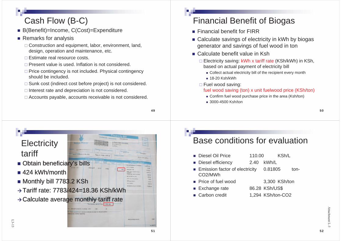
Cash Flow (B C)Cash Flow (B-C)B(Benefit)=Income, C(Cost)=ExpenditureRemarks for analysis
Construction and equipment, labor, environment, land, q p , , , ,design, operation and maintenance, etc.Estimate real resource costs.Present value is used. Inflation is not considered.Price contingency is not included. Physical contingency g y y g yshould be included.Sunk cost (indirect cost before project) is not considered.Interest rate and depreciation is not considered.Accounts payable, accounts receivable is not considered.
49
Financial Benefit of BiogasFinancial Benefit of BiogasFinancial benefit for FIRRCalculate savings of electricity in kWh by biogas generator and savings of fuel wood in tongenerator and savings of fuel wood in tonCalculate benefit value in Ksh
Electricity saving: kWh x tariff rate (KSh/kWh) in KShElectricity saving: kWh x tariff rate (KSh/kWh) in KSh, based on actual payment of electricity bill
Collect actual electricity bill of the recipient every monthCollect actual electricity bill of the recipient every month18-20 Ksh/kWh
Fuel wood saving: gfuel wood saving (ton) x unit fuelwood price (KSh/ton)
Confirm fuel wood purchase price in the area (Ksh/ton)3000-4500 Ksh/ton
50
El t i itElectricity tarifftariffObtain beneficiary’s billsObtain beneficiary’s bills424 kWh/month424 kWh/monthMonthly bill 7783 2 KShMonthly bill 7783 2 KShMonthly bill 7783.2 KShMonthly bill 7783.2 KShTariff rate: 7783/424=18.36 KSh/kWhTariff rate: 7783/424=18.36 KSh/kWhCalculate average monthly tariff rateCalculate average monthly tariff rate
51
Base conditions for evaluationBase conditions for evaluationDi l Oil P i 110 00 KSh/LDiesel Oil Price 110.00 KSh/LDiesel efficiency 2.40 kWh/LE i i f t f l t i it 0 81805 tEmission factor of electricity 0.81805 ton-CO2/MWhPrice of fuel wood 3 300 KSh/tonPrice of fuel wood 3,300 KSh/tonExchange rate 86.28 KSh/US$C b dit 1 294 KSh/t CO2Carbon credit 1,294 KSh/ton-CO2
52

Benefit of Economic AnalysisBenefit of Economic AnalysisBenefit of diesel generation saving
Di l i 105 110 KSh/L ffi i 2 3 kWh/LDiesel price: 105-110 KSh/L, efficiency: 2-3 kWh/LBenefit of CO2 emission reduction by biogas
l i i ielectricity generationEmission Factor of diesel oil: 0.81805 ton-CO2/kWhCarbon credit 5-20 US$/ton-CO2 (depends on international trend)
Benefit from fuelwood savingFuelwood carbon absorption benefitpFuel wood carbon off-set benefitFuel wood economic value: protection of forestFuel wood economic value: protection of forest
53
Benefit of fuel wood savingBenefit of fuel wood saving Carbon absorption
Carbon Absorption A = W x E x (1+R) x C%ton-CO2 reduction = A x 44/12ton CO2 reduction A x 44/12Where,W Weight of saved tree, ton 1E Coefficient for tree and branch addition 1 52E Coefficient for tree and branch addition 1.52R Ratio of ground/underground portion 0.26C% Carbon component percentage 0.5
CO2 3 51ton-CO2 3.51
Carbon off-setton-CO2 reduction = W x (1-M/100) x H x EF x BEWhere,W Weight of saved tree, ton 1g ,M Moisture content, % 10H Calorific value GJ/ton 15.5EF Emission coefficient of coal ton-CO2/GJ 0 09
54
EF Emission coefficient of coal, ton CO2/GJ 0.09BE Boiler efficiency ratio (fuel wood/fossil fuel) 1ton-CO2 1.26
Source: Forestry and Forest Products Research Institute, Japan
Calculation of Carbon AbsorptionCalculation of Carbon AbsorptionCoefficient ofBranch addition1.4-1.9 (1.52 average for broadleaf forest)
Carbon component percentage = 50%
Molecular numberC = 12C 12CO2 = 44WCO2 = 44/12 x WC
Ratio of underground /ground portion0.26 average for broadleaf forest
55
CO2 absorption of 1 ton fuel wood = 1 ton x 1.52 x (1+0.26) x 0.5 x 44/12 = 3.51 ton-CO2If 10US$/ton-CO2, 1 ton fuel wood = 35.1 US$ carbon credit value
Economic Value of Forest PreservationAmount of carbon storage 190 C-ton/ha
Economic Value of Forest Preservation
Weight of wood body 198.4 ton/haEconomic value per area 921,165 KSh/haEconomic value per ton fuel wood 4,643 KSh/ton
The economic value is much depending on condition, i d l i f f I i h jassumption, and location of forest. It requires another project to
assess actual economic value of forest. Here, the estimation of other project in Kenya was referred.
Source: The Role and Contribution of Montane Forests and Related Ecosystem Services to the Kenyan Economy”, 2012, UNEPy y y , ,
56

Economic Analysis of Nyeri HSAnnual benefit 620,758 KShProject investment cost 3,755,264 KShDiscount rate 10% Cash Flow (CF)=Project year 30 YearsTax 0% (Exempted)
Cost
Cash Flow (CF)Benefit – total Cost
InitialInvestment
TAXRehabili
tationO&M Total Cost
KSh KSh KSh KSh KSh KSh KSh1 2012 0% 0 3 755 264 0 0 0 3 755 264 3 755 264
No. YearRevenue
%Benefit Cash Flow
1 2012 0% 0 3,755,264 0 0 0 3,755,264 -3,755,2642 2013 100% 620,758 0 0 17,000 17,000 603,7583 2014 100% 620,758 0 0 17,000 17,000 603,7584 2015 100% 620,758 0 0 17,000 17,000 603,758
.
5 2016 100% 620,758 0 0 17,000 17,000 603,7586 2017 100% 620,758 0 187,763 17,000 204,763 415,995
=IRR(CF1+CF2+…)29 2040 100% 620,758 0 0 17,000 17,000 603,75830 2041 100% 620,758 0 0 17,000 17,000 603,758
. IRR(CF1 CF2 …)
T 18,001,991 3,755,264 0 938,816 493,000 5,187,080 12,814,911
NPV(Benefit)= 5,287,510 NPV(Cost)= 3,812,466EIRR= 15.09%NPV= 1,475,043=NPV(DR, (CF1+CF2+…))
57
NPV 1,475,043B/C= 1.3869
( ( 1 2 ))
=NPV(Benefit)/NPV(Cost)
Result of Financial/Economic EvaluationResult of Financial/Economic EvaluationItem Unit Nyeri High
SchoolRware High
SchoolLitein High
School
KipsigisGirls High
S h l
MukumuGirls High
S h l
CardinalOtunga
Hi h S h lSchool School High SchoolProject Cost KSh 3,755,264 1,453,168 6,861,967 3,658,669 4,271,187 4,703,232Planned gas production for fuelwood saving m3/yr 6,248 3,285 4,466 1,533 4,822 4,411Planned gas production for electricity saving m3/yr 2,321 0 4,380 5,179 2,683 4,380yElectricity tariff rate KSh/kWh 19.7 8.7 18.1 19.5 17.9 19.9Annual planned generated energy kWh/yr 2,321 4,380 5,179 2,683 4,380Annual planned fuelwood Saving ton/yr 36.3 19.1 25.9 8.9 28.0 25.6Financial benefit KSh/yr 165,466 62,945 164,856 130,357 174,026 171,690yRecovery year yr 23 23 42 28 25 27
Benefit of diesel generation saving KSh/yr 106,356 0 200,750 237,353 122,959 200,750Benefit of CO2 emission reduction by
KSh/ 2 457 0 4 637 5 483 2 840 4 637y
biogas generationKSh/yr 2,457 0 4,637 5,483 2,840 4,637
Benefit from fuelwood saving KSh/yr 119,717 62,945 85,578 29,374 126,005 84,528Fuelwood carbon absorption benefit KSh/yr 164,854 86,677 117,844 40,449 127,242 116,398Fuel wood carbon off-set benefit KSh/yr 58,947 30,993 42,137 14,463 45,498 41,620y , , , , , ,Fuel wood economic value KSh/yr 168,427 88,555 120,397 41,326 130,000 118,920Total economic benefit KSh/yr 620,758 269,170 571,344 368,448 554,544 566,853EIRR 15.09% 16.44% 5.85% 7.79% 11.27% 10.26%
Ranking 1 5 6 4 2 3
58
gShadow exchange rate is not considered in financial cost.
THANK YOU
59

Attachment L-4-1
Pre Feasibility Study on Biogas for Schools
PRE FEASIBILITY STUDY ON BIOGAS SYSTEMS FOR SCHOOLS IN KENYA
Caroline Kelly, Gilbert Gichunge
Rural Electrification Authority. The Chancery, Valley Road, P.O Box 34585 00100 Nairobi, Kenya
E mail/mobile: [email protected] (0722230120), [email protected] (0726563172)
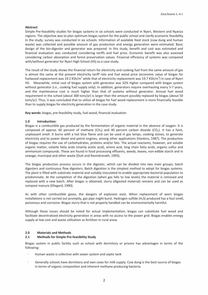
Attachment L-4-1
2
AbstractSimple Pre feasibility studies for biogas systems in six schools were conducted in Nyeri, Western and Nyanzaregions. The objective was to plan optimum biogas system for the public school and clarify economic feasibility.In the study, survey was conducted in six schools. Information of available feed stock (cow dung and humanwaste) was collected and possible amount of gas production and energy generation were estimated. Basicdesign of the bio digester and generator was prepared. In this study, benefit and cost was estimated andfinancial evaluation was conducted considering tariffs and fuel price. Economic benefit was also assessedconsidering carbon absorption and forest preservation values. Financial efficiency of systems was comparedwith/without generator for Nyeri High School (HS) as a case study.
The result of the study shows the financial return for electricity and cooking fuel from the same amount of gasis almost the same at the present electricity tariff rate and fuel wood price (economic value of biogas forfuelwood replacement was 19.2 KSh/m3 while that of electricity replacement was 19.7 KSh/m3) in case of NyeriHS. Meanwhile, initial cost of biogas system with generator was 32% higher compared with biogas systemwithout generator (i.e., cooking fuel supply only). In addition, generators require overhauling every 5 7 years,and the maintenance cost is much higher than that of systems without generator. Annual fuel woodrequirement in the school (about 300 tons/yr) is larger than the amount possibly replaced by biogas (about 50tons/yr). Thus, it was concluded that to utilize all biogas for fuel wood replacement is more financially feasiblethan to supply biogas for electricity generation in the case study.
Key words: biogas, pre feasibility study, fuel wood, financial evaluation
1.0 Introduction:Biogas is a combustible gas produced by the fermentation of organic material in the absence of oxygen. It iscomposed of approx. 60 percent of methane (CH4) and 40 percent carbon dioxide (CO2). It has a faint,unpleasant smell. It burns with a hot blue flame and can be used in gas lamps, cooking stoves, to generateelectricity and to power diesel and petrol engines, among other applications (Hankins, 1987). The productionof biogas requires the use of carbohydrates, proteins and/or fats. The actual reactants, however, are solubleorganic matter, volatile fatty acids (mainly acetic acid), amino acid, long chain fatty acids, organic sulfur andammonium compounds. These are found in food processing effluents, weeds, leaves, non edible starch and insewage, municipal and other waste (Dutt and Ravindranath, 1993).
The biogas production process occurs in the digester, which can be divided into two main groups; batchdigesters and continuous flow digesters. Batch digestion is the simplest method to adopt for biogas systems.The plant is filled with substrate material and suitably inoculated to enable appropriate bacterial population topredominate. At the completion of the digestion (when gas falls to low levels) the material is removed andreplaced with a new batch. After biogas is obtained, slurry (digested material) remains and can be used ascompost manure (Ellegard, 1990).
As with other combustible gases, the dangers of explosion exist. When replacement of worn biogasinstallations is not carried out promptly, gas pipe might burst. Hydrogen sulfide (H2S) produced has a foul smell,poisonous and corrosive. Biogas slurry that is not properly handled can be environmentally harmful.
Although those issues should be noted for actual implementation, biogas can substitute fuel wood andfacilitate decentralized electricity generation in areas with no access to the power grid. Biogas enables energysupply at low cost and waste utilization as fertilizer in rural areas
2.0 Materials and Methods2.1 Methods for Simple Pre feasibility Study
Biogas system in public facility such as school with dormitory or prisons has advantages in terms of thefollowing:
Human waste is collective with sewer system and septic tank
Generally schools have dormitory and own cows for milk supply. Cow dung is the best source of biogasin terms of organic composition and inherent methane producing bacteria.
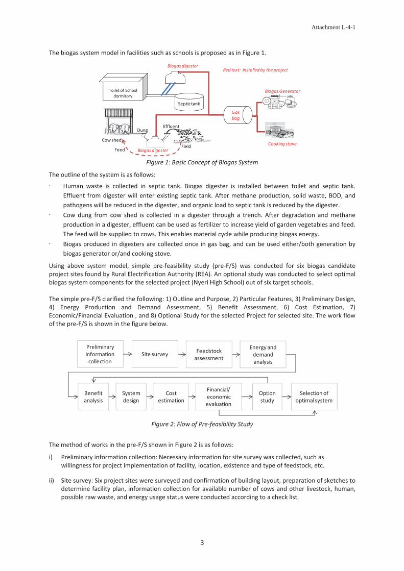
Attachment L-4-1
3
The biogas system model in facilities such as schools is proposed as in Figure 1.
Figure 1: Basic Concept of Biogas System
The outline of the system is as follows:
Human waste is collected in septic tank. Biogas digester is installed between toilet and septic tank.Effluent from digester will enter existing septic tank. After methane production, solid waste, BOD, andpathogens will be reduced in the digester, and organic load to septic tank is reduced by the digester.Cow dung from cow shed is collected in a digester through a trench. After degradation and methaneproduction in a digester, effluent can be used as fertilizer to increase yield of garden vegetables and feed.The feed will be supplied to cows. This enables material cycle while producing biogas energy.Biogas produced in digesters are collected once in gas bag, and can be used either/both generation bybiogas generator or/and cooking stove.
Using above system model, simple pre feasibility study (pre F/S) was conducted for six biogas candidateproject sites found by Rural Electrification Authority (REA). An optional study was conducted to select optimalbiogas system components for the selected project (Nyeri High School) out of six target schools.
The simple pre F/S clarified the following: 1) Outline and Purpose, 2) Particular Features, 3) Preliminary Design,4) Energy Production and Demand Assessment, 5) Benefit Assessment, 6) Cost Estimation, 7)Economic/Financial Evaluation , and 8) Optional Study for the selected Project for selected site. The work flowof the pre F/S is shown in the figure below.
Figure 2: Flow of Pre feasibility Study
The method of works in the pre F/S shown in Figure 2 is as follows:
i) Preliminary information collection: Necessary information for site survey was collected, such aswillingness for project implementation of facility, location, existence and type of feedstock, etc.
ii) Site survey: Six project sites were surveyed and confirmation of building layout, preparation of sketches todetermine facility plan, information collection for available number of cows and other livestock, human,possible raw waste, and energy usage status were conducted according to a check list.
Toilet of Schooldormitory
Septic tank
Cow shed
GasBag
Biogas digester
Biogasdigester
BiogasGenerator
Cooking stoveField
Effluent
Red text: installed by theproject
Dung
Feed
Preliminaryinformationcollection
Site survey Feedstockassessment
Energy anddemandanalysis
Costestimation
Financial/economicevaluation
Benefitanalysis
Optionstudy
Selectionofoptimalsystem
Systemdesign

Attachment L-4-1
4
iii) Feedstock assessment: Cow dung and human waste is the main feedstock for school biogas system. Theamount of feedstock available in the facility was assessed. The amount of biogas production per kg of cowdung was measured 0.023 0.04 m3/kg (Gunter U, 2011). With application of the average of thisexperimental value, the biogas production volume per cow was estimated with the following formula:
Where, Vc: Volume of biogas production from cow dung (m3/year)Nc: Number of cows in facilityWd: Average cow dung production in kg per cow
The value Wd is variable depending on cow conditions such as age, weight, nutrient status, etc. Here, 20kg/cow is applied.
The volume of biogas production per person was reported to be 0.02 0.028 m3/person/day in theexperiment in Uganda (E.Menya and Y. Alokore, 2013). With application of average value of this, theamount of biogas production from human waste was estimated with the following formula:
Where, Vh: Volume of biogas production from human waste (m3/year)Nh: Number of persons utilizing the toilet connected to a digester in facilityO: Body weight ratio, average weight of persons/average weight of adultsD: Number of regular days (= 365 – number of long holidays))R: Toilet usage ratio (percentage of toilet use connected to the digester)
The value O depends on the student age. For high schools, 0.8 was applied. The value D was estimatedwith school holidays when students and teachers are absent. In this study, 0.75 was applied. The value Rwas estimated with assumption of how often the toilet connected with digester is used, when differenttypes of toilets, which are not connected to a digester, are installed in a facility. This value was determinedby interviews on situation of respective school (0.3 0.95).
iv) Energy and demand analysis: Energy usage and energy demand in the target facility was assessed bycollecting data of monthly electricity bills and amount of actual usage of fuel wood.
v) Benefit analysis: The benefit of biogas system consists of fuel wood saving and electricity saving, and canbe calculated by the amount of saved fuel wood and/or electricity. The benefit of fuel wood saving wascalculated with the following formula:
,
Where, Sf: Saved amount of fuel wood by biogas (tons/year)Vcw and Vhw : Volume of biogas Vc and Vh allocated for cooking fuel saving (m
3)Cgas: Calorific value of produced biogas (MJ/m3)Cwood: Calorific value of fuel wood (MJ/ton)Estove: Efficiency of cooking stoveBf: Benefit of fuel wood saving (Ksh)Pwood: Price of fuel wood (Ksh/ton)
Here, calorific value of produced biogas 20 MJ/m3 (M. Kaltschmittm, 2003) was applied for Cgas. Thecalorific value of fuel wood, Cwood, is variable depending on moisture percentage and condition of wood.For dry wood, the value is indicated to be 0.019 0.0225 MJ/ton (Hubbard W., et al., 2007). The value of0.02 is applied in this study. Estove value depends on the actual cooking stove type that the facility uses,and 10% (N.Shrestha, 2001) is applied for Estove here. Fuel wood price, Pwood, is also variable dependingon local condition, and was set to be 3,300 kSh/ton from local interviews.
The benefit of electricity saving is calculated with the following formula.
,Where, Eg: Saved amount of electric energy (kWh)

Attachment L-4-1
5
Vce and Vhe : Volume of biogas Vc and Vh allocated for electricity saving (m3)
Ge: Efficiency of biogas generator (kWh/m3)Be: Benefit of electricity saving (Ksh.)T: Power tariff rate (Ksh./kWh)
The efficiency of biogas generator, Ge depends on specification of biogas engine generator. Here, 1.0kWh/m3 was applied according to manufactures’ specification in the past project. T, tariff rate isdetermined with actual monthly bills of the respective facilities, which was 8.7 19.9 Ksh/kWh.
vi) System design: System design layout was prepared according to sketches in the survey. The size ofdigester was determined with the following formula (Gunter U et al., 2011 and Martin G et al, 2012)
,
Where, Vdc: Volume of cow dung digester (m3)Vdh: Volume of human waste digester (m3)
The size of generator was determined according to required specific load demands such as water pump orlighting.
vii) Cost estimation: The cost of biogas system was estimated by unit cost estimation with quantity or capacityin the past result of REA biogas projects.
viii) Financial and Economic Evaluation: The financial benefit is the same as what was estimated in the benefitassessment. The total economic benefit Bteb is calculated with the following formula.
The meanings of respective benefit items are explained in Table 1.
Table 1: Economic BenefitB Type of Economic Benefit Explanation
BebBenefit as electricity savingfrom diesel oil
When electricity is generated using biogas, the electric energy can be consideredto save electricity from grid connected diesel generation system in grid, sincediesel generation is the most expensive method. The cost of electricity fromdiesel generation can be considered as economic benefit in place of gridelectricity tariff, different from financial benefit. Diesel Oil Price 110.00 KSh/L andDiesel efficiency 2.40 kWh/L was applied.
BcrBenefit of carbon reduction bybiogas generation
CO2 emission reduction is expected from biogas generation since it replacesenergy from diesel generation. Emission factor of diesel oil can be applied tocalculate economic benefit. Emission factor of electricity 0.81805 ton CO2/MWhand 1,294 KSh/ton CO2 was applied (with exchange rate 86.28 KSh/US$).
Bf Benefit from fuelwood saving The benefit is the same as financial benefit of fuel wood saving.
BfabFuelwood carbon absorptionbenefit
Saved fuel wood by biogas can absorb CO2 in a forest. The carbon credit with theabsorption of CO2 amount is considered to be economic benefit.
BfcoFuelwood carbon off setbenefit
As well as electricity, saved amount of fuelwood is considered to replace coal,and corresponding amount of CO2 from the replaced coal. This is considered tobe economic benefit of carbon reduction.
BfevFuel wood economic value toprevent deforestation
Saving of losses in economic sectors resulting from deforestation is counted aseconomic benefit. The components of this economic value are: growing of cropsand horticulture, fishing, water supply, public administration and defense,deforestation effects on carbon sequestration, and deforestation effects onhealth, which was quantified as much as 921,165 KSh/ha (Jackie C, 2012).
3.0 Results3.1 Overall Pre F/SPre F/S was conducted for six sites in Kenya. The institutions were visited to assess the availability of feedstock,their current energy demand and economic benefit of the biogas system. In addition to the work flow up toeconomic evaluation, Nyeri HS was selected for optional study. Summary results from those other than NyeriHS are indicated in Table 2. The result for Nyeri HS is described in detail later.

Attachment L-4-1
6
Table 2: Summary of the Result and Plan of Other Institutions
DescriptionName of institution
Litein HS Rware HS Kipsigis Girls HS Mukumu Girls HS Cardinal OtungaHS
Estimatedfeedstock
17 cows and 1015students
9 cows and 600students
13 cows1000 students
14 cows1300students
10 cows1000students
Possible gasproductionper day
Cowdung:12m3
Humanwaste:16m3Cowdung:9m3
Humanwaste:(no septic tank)
Cowdung:4.2m3
Humanwaste:23m3
Cowdung:7.3m3
Humanwaste:17m3
Cowdung:12m3
Humanwaste:16.1m3
Digestervolume
Cowdung: 32m3
Human waste:60m3Cowdung: 24m3 Cowdung:16m3
Humanwaste:50m3Cowdung:28m3
Humanwaste:60m3Cowdung: 32m3
Humanwaste:6om3
Total gasproduction
28m3/day 9m3/day 18.9m3/day 24.9m3/day 28.1m3/day
Amount offuel woodreduction
25.9 tons/yr 19.1 tons/yr 8.9 tons/yr 28.0 tons/yr 25.6 tons/yr
Benefit ofsavingelectricity
Ksh. 79,278/yr No plan forelectricity
Ksh. 100,983/yr Ksh. 48,021/yr Ksh. 87,162/yr
Benefit of fuelwood saving
Ksh. 85,578/yr 62,945 Ksh/yr Ksh. 29,374/yr Ksh. 126,005/yr Ksh. 84,528/yr
Cost 6.9 million Ksh 1.7 million Ksh 3.8 million Ksh 4.3 million Ksh 4.7 million Ksh
As a result, the project recovery year was within 30 years, ranged from 23 years (Rware HS) to 28 years (KipsigisGirls HS), and considered to be feasible, except for 42 years in Litein HS. Since facilities are isolated and civil costwas high, the project in Litein HS is not considered to be feasible. Economic internal rate of return wascalculated to be from 5.8% (Litein HS) to 16.4% (Rware HS).
3.2 Overview of Nyeri High SchoolNyeri high school was established in 1924 as a missionary school, which was later on reformed into a high schoolin 1950. The current population in the school is approximately 1000 persons including teaching andnon teaching staff. At the time of visit, there were 10 cows and 15 pigs. The agricultural activities in the schoolinclude; nappier grass, sweet potato, sukuma wiki, and recently fishpond for rearing tilapia fingerlings, all theseactivities would utilize the bio slurry.
3.3 Purpose of the Project in Nyeri HS and Energy and Demand AssessmentThe School consumes large amounts of both electricity and fuel wood to support the activities within theschool. Electricity is consumed mainly for lighting. A diesel generator (38.5 kVA) is on standby incase ofblackout, and it consumes diesel oil approximately 480 L/yr. Fuel wood is consumed at 300 tons/year for dailymeals for students and teachers. The financial burden of electricity is about 1.5 mil KSh/year and that of fuelwood is 0.8mil Ksh/Yr. Electricity supply by biogas is expected to contribute toward mitigation of electricityand fuel wood usage in the school.
3.4 Preliminary Design in Nyeri HSThe demand for biogas is for (i) cooking fuel and (ii) electricity lighting in boarding buildings. The proposedsystems are (i) digester connected with cow shed for electricity generation system and (ii) digester connectedfrom toilet for cooking fuel use. The system components are shown in the table below.
Table 3: Cow Dung Digester for Electricity Table 4: Human Waste Digesterfor Cooking fuel
The digester for cow dung will be located at a garden area below a cow shed. The layout was considered in a waythat it would utilize gravity to transport cow dung . Effluent supply as fertilizer for a garden is also by gravity.
Description Qty Unit RemarksNos of cows 17 to be increased from 10 nosDigester size 32 m3Assumed feedstock input 400 kg/dayPossible gas production 12 m3/dayGenerated energy 12 kWh 1kWh/m3Electric energy demand 8.5 kWh Light, 59 nos of 36W, 4hrs
Description Value UnitUtilization ratio 0.54 Boarding toilet usage ratio 0.67 Student/adult weight 0.80Nos of student utilizing dorm toilet 950 nosConverted nos of person for biogas 509 nosDigester volume 60 m3Gasproduction amount 15.3 m3/day

Attachment L-4-1
7
3.5 Benefit AssessmentTotal expected amount of gas production isapproximately 8,568 m3/year, of which 2,321 m3 isplanned to be used for generation and 6,248m3 forcooking stove. Amount of electricity saving will be2,321 kWh and amount of fuel saving will be 36.3tons/year. This corresponds to 4% of total electricityusage and 12% of fuel wood use in the school. Theunit cost of electricity at the school is 19.7 KSh/kWh,therefore the annual saving will be 45,748 KSh/yearfor electricity. The unit cost of fuel wood is 3,300KSh/ton, therefore the annual saving for fuel woodwill be 119,717 KSh. In total, the annual benefit ofbiogas system will be 165,466 KSh/year.
3.5 Cost EstimationThe cost for the system was estimated asin Table 5. As the optional study, systemwithout electricity generation was alsostudied. This is because usage of fuelwood by the school is more than thereplacing amount of biogas even if allbiogas is used for cooking fuel supplyonly. The cost with generator wasestimated to be about 3.8 million KSh,while that of without generator wasabout 2.8 million KSh. The installationcost of biogas system with generator is32% higher that that of withoutgeneration system. The details are shownin Table 5. In addition, generators requireoverhauling every 5 7 years, and themaintenance cost is high, which wasconsidered in the cash flow.
3.6 Results of Financial and EconomicEvaluationAs the result shown in Table 6, thefinancial benefit for the system withgenerator was 165,466 Ksh/yr, higherthan without generator (cooking fuelsupply only), 164,181 Ksh/yr. However,since investment cost with generator willbe much higher, recovery year of thesystem without generator has advantage,17 years, while that of the system withgenerator was 23 years.
Meanwhile, economic benefit will belarger in the system without generator(702,086 KSh/yr) than system withgenerator (620,758 KSh/yr), sinceeconomic benefit of forest protection
Figure 3: Layout of Nyeri School Biogas System
Item
Qty unit KSh Qty unit KShBiogas Digester for Toilet 60 m3 413,720 60 m3 413,720Biogas Digeter for Cow Shed 32 m3 340,444 32 m3 340,444Excavation and civil works 1 lot 188,830 1 lot 188,830Additional toilet facility with septic tankGas holding steel tank and connection valve 2 nos 100,800 2 nos 100,800Bigoas flow meter 2 nos 73,000 2 nos 73,000PVC gas bag 1 nos 411,000 1 nos 411,000Biogas generator 7 kVA 240,000 kVAEnergy meter 1 nos 50,000 nosDistribution board, switch gear 1 nos 150,500 nosBiogas filter and solenoid valve 1 nos 106,500 1 nos 106,500Cable work 1 lot 200,000 lotPipe work 1 lot 250,000 1 lot 250,000Fence and safety arrangement 1 lot 118,000 1 lot 118,000Subtotal 2,642,794 2,002,294
Detailed design and drawing 1 lot 246,000 1 lot 186,380Testing, commissioning, training 1 lot 363,500 1 lot 275,403
Total Cost 3,252,294 2,464,077Total Cost adjusted with Inflation 2010/13 4.91%/yKsh 3,755,264 4.91%/yKsh 2,845,149
Nyeri High Schoolwithout generator
Nyeri High Schoolwith Generator
Table 5: Cost Estimation with/without Generation
Item Unit Nyeri High Schoolwith generator
Nyeri High Schoolwithout generator
Project Cost KSh 3,755,264 2,845,149Planned gas production for fuelwood saving m3/yr 6,248 8,568Planned gas production for electricity saving m3/yr 2,321 0Electricity tariff rate KSh/kWh 19.7 19.7Annual planned generated energy kWh/yr 2,321 0Annual planned fuelwood Saving ton/yr 36.3 49.8Financial benefit KSh/yr 165,466 164,181Recovery year yr 23 17
Benefit of diesel generation saving KSh/yr 106,356 0Benefit of CO2 emission reduction bybiogas generation
KSh/yr 2,457 0
Benefit from fuelwood saving KSh/yr 119,717 164,181Fuelwood carbon absorption benefit KSh/yr 164,854 226,082Fuel wood carbon off-set benefit KSh/yr 58,947 80,840Fuel wood economic value KSh/yr 168,427 230,982Total economic benefit KSh/yr 620,758 702,085EIRR 15.09% 24.18%Shadow exchange rate is not considered in financial cost.
Table 6: Cost Estimation with/without Generation
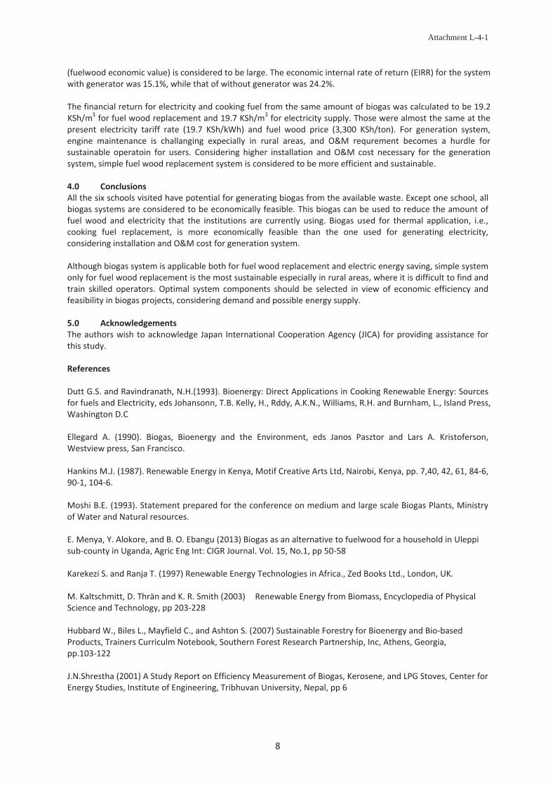
Attachment L-4-1
8
(fuelwood economic value) is considered to be large. The economic internal rate of return (EIRR) for the systemwith generator was 15.1%, while that of without generator was 24.2%.
The financial return for electricity and cooking fuel from the same amount of biogas was calculated to be 19.2KSh/m3 for fuel wood replacement and 19.7 KSh/m3 for electricity supply. Those were almost the same at thepresent electricity tariff rate (19.7 KSh/kWh) and fuel wood price (3,300 KSh/ton). For generation system,engine maintenance is challanging expecially in rural areas, and O&M requrement becomes a hurdle forsustainable operatoin for users. Considering higher installation and O&M cost necessary for the generationsystem, simple fuel wood replacement system is considered to be more efficient and sustainable.
4.0 ConclusionsAll the six schools visited have potential for generating biogas from the available waste. Except one school, allbiogas systems are considered to be economically feasible. This biogas can be used to reduce the amount offuel wood and electricity that the institutions are currently using. Biogas used for thermal application, i.e.,cooking fuel replacement, is more economically feasible than the one used for generating electricity,considering installation and O&M cost for generation system.
Although biogas system is applicable both for fuel wood replacement and electric energy saving, simple systemonly for fuel wood replacement is the most sustainable especially in rural areas, where it is difficult to find andtrain skilled operators. Optimal system components should be selected in view of economic efficiency andfeasibility in biogas projects, considering demand and possible energy supply.
5.0 AcknowledgementsThe authors wish to acknowledge Japan International Cooperation Agency (JICA) for providing assistance forthis study.
References
Dutt G.S. and Ravindranath, N.H.(1993). Bioenergy: Direct Applications in Cooking Renewable Energy: Sourcesfor fuels and Electricity, eds Johansonn, T.B. Kelly, H., Rddy, A.K.N., Williams, R.H. and Burnham, L., Island Press,Washington D.C
Ellegard A. (1990). Biogas, Bioenergy and the Environment, eds Janos Pasztor and Lars A. Kristoferson,Westview press, San Francisco.
Hankins M.J. (1987). Renewable Energy in Kenya, Motif Creative Arts Ltd, Nairobi, Kenya, pp. 7,40, 42, 61, 84 6,90 1, 104 6.
Moshi B.E. (1993). Statement prepared for the conference on medium and large scale Biogas Plants, Ministryof Water and Natural resources.
E. Menya, Y. Alokore, and B. O. Ebangu (2013) Biogas as an alternative to fuelwood for a household in Uleppisub county in Uganda, Agric Eng Int: CIGR Journal. Vol. 15, No.1, pp 50 58
Karekezi S. and Ranja T. (1997) Renewable Energy Technologies in Africa., Zed Books Ltd., London, UK.
M. Kaltschmitt, D. Thrän and K. R. Smith (2003) Renewable Energy from Biomass, Encyclopedia of PhysicalScience and Technology, pp 203 228
Hubbard W., Biles L., Mayfield C., and Ashton S. (2007) Sustainable Forestry for Bioenergy and Bio basedProducts, Trainers Curriculm Notebook, Southern Forest Research Partnership, Inc, Athens, Georgia,pp.103 122
J.N.Shrestha (2001) A Study Report on Efficiency Measurement of Biogas, Kerosene, and LPG Stoves, Center forEnergy Studies, Institute of Engineering, Tribhuvan University, Nepal, pp 6

Attachment L-4-1
9
Gunter U., Romas R., and Stanley C. (2011) Bigoas Construction Manual, Deutsche Gesellschaft fürInternationale Zusammenarbeit (GIZ) GmbH, Promotion of Private Sector Development in Agriculture (PSDA),PP21
Martin G., Alain O., Christian L., Christian Z. (2012) Ensuring Appropriateness of Biogas Sanitation Systems forPrisons Analysis from Rwanda, Nepal and the Philippines, Technologies for Sustainable Development,Chapter: 6, pp.57 72
Jackie C., Rita S., Pablo M., Thierry D. O., Christian L., Melanie W., Amelia B., and Jan B., (2012). The Role andContribution of Montane Forests and Related Ecosystem Services to the Kenyan Economy, UNDP
JICA (2014). Progress Report 3 for Project for Establishment of Rural Electrification Model Using RenewableEnergy, Japan International Cooperation Agency

PRE FEASIBILITY STUDY ONBIOGAS SYSTEMS FOR SCHOOLS IN KENYA
Biogas digesterRed text: installed by theproject
Preliminaryinformationcollection
Site survey Feedstockassessment
Energy anddemandanalysis
Costestimation
Financial/economicevaluation
Benefitanalysis
Optionstudy
Selectionofoptimalsystem
Systemdesign
Objective: Biogas is combustible gas produced by anaerobicfermentation of organic material. Biogas has approx. 60% methane(CH4) , 20 MJ/m3 calorific value. Biogas can substitute fuel wood andelectricity. Slurry after fermentation becomes fertilizer.Pre Feasibility Study to install 6 schools biogas system wasconducted to assess benefit and conduct economic evaluation.
V : Biogas volume from cow dung (m3/year)
Figure 1 Work Flow of Pre Feasibility Study
(1) Feedstock Assessment : Cow dung
Authors: Caroline Kelly([email protected]), Gilbert Gichunge ([email protected] ) , Renewable Energy Dept., Rural Electrification Authority
Toilet of Schooldormitory
Septic tank
GasBag
Biogas digester
Biogasdigester
BiogasGenerator
Cooking stoveField
Effluent
Red text: installed by theproject
Cowshed
Vh: Biogas volume from human waste (m3/year)Nh: Number of persons utilizing toilets for digesterO: Body weight ratio (% of adult)D: Number of operation daysR: Utilization ratio (%of toilet for digester use )
Cow dung: Digester Size (m3) = 1.89 x nos of cowHuman waste: Size (m3) = 0.1 x nos of personGen set, Pipeline, Civil/Electrical Works, etc
Eg: Saved amount of electric energy (kWh)Vce and Vhe : Volume of biogasVc and Vh :allocated for electricity saving (m3)Ge: Efficiency of biogas generator (kWh/m3)B : Benefit of electricity saving (KSh )
Sf: Saved amount of fuel wood by biogas (tons/year)Vcw &Vhw : Biogas volume for cooking fuel saving (m3)Cgas: Calorific value of produced biogas (MJ/m3)Cwood: Calorific value of fuel wood (MJ/ton)E : Efficiency of cooking stove
Vc: Biogas volume from cow dung (m3/year)Nc: Number of cows in facilityWd: Average cow dung production (kg/cow)
Figure 2 Biogas Generation System Model
(1) Feedstock Assessment : Cow dung
(2) Feedstock Assessment : Human Waste
(3) Benefit: Electricity Saving(4) Benefit: Fuelwood Saving (5) Design and Cost Estimation
/
Vc and Vh :allocated for electricity saving (m )Ge: Efficiency of biogas generator (kWh/m3)Be: Benefit of electricity saving (KSh.)T: Power tariff rate (KSh./kWh)
Cgas: Calorific value of produced biogas (MJ/m )Cwood: Calorific value of fuel wood (MJ/ton)Estove: Efficiency of cooking stoveBf: Benefit of fuel wood saving (KSh)Pwood: Price of fuel wood (KSh/ton)
Table 5 Case Study Result of SystemWith/Without Generator
Table 1 Biogas Economic Benefits
Table 2 Summary of Pre Feasibility Study for Six Schools in KenyaB Type of Economic Benefit Value*
Bteb Total economic benefit Summation of values velow.
BedBenefit as electricity savingfrom diesel oil
From diesel oil price and dieselgeneration efficiency
BcrBenefit of carbon reductionby biogas generation
when 0.81805 ton-CO2/MWh and1,294 KSh/ton-CO2, 1059 KSh/MWh
Bf Benefit from fuelwood saving From fuel wood price and savedamount of wood
BfabFuelwood carbon absorptionbenefit
1 ton fuel wood saving corresponds to3.51 ton-CO2
BfcoFuelwood carbon off-setbenefit
1 ton fuel wood saving corresponds to1.26 ton-CO2
BfevFuel wood economic value toprevent deforestation
Economic value per ton fuelwood4,643 KSh/ton
* All values here are subject to be changed according to carbon credit, emission coefficient, exchange rate, and method of socio-economic calculation. For detail, refer to the guideline.
(6) Financial/Economic Evaluation
(7) Result of Pre Feasibility
(8) O i S di f N i Hi h S h l
Litein HS Rware HS Kipsigis Girls HS Mukumu Girls HS Cardinal Otunga HS13 cows 14 cows 10 cows1000 students 1300students 1000students
Cowdung:12m3 Cowdung:9m3 Cowdung:4.2m3 Cowdung:7.3m3 Cowdung:12m3
Humanwaste:16m3 Humanwaste:(no septic tank)
Humanwaste:23m3 Humanwaste:
17m3Humanwaste:
16.1m3
Cowdung: 32m3 Cowdung:16m3 Cowdung:28m3 Cowdung: 32m3
Human waste:60m3 Humanwaste:50m3 Humanwaste:60m3 Humanwaste:60m3
Tota l gas production 28m3/day 9m3/day 18.9m3/day 24.9m3/day 28.1m3/day
Fuel wood reduction 25.9 tons/yr 19.1 tons/yr 8.9 tons/yr 28.0 tons/yr 25.6 tons/yr
Eelctrici ty saving benefi t Ksh. 79,278/yr No electrici ty Ksh. 100,983/yr Ksh. 48,021/yr Ksh. 87,162/yr
Fuel wood saving benefi t Ksh. 85,578/yr 62,945 Ksh/yr Ksh. 29,374/yr Ksh. 126,005/yr Ksh. 84,528/yr
Cost 6.9 mi l l ion Ksh 1.7 mi l l ion Ksh 3.8 mi l l ion Ksh 4.3 mi l l ion Ksh 4.7 mi l l ion Ksh
Digester volumeCowdung: 24m3
DescriptionSchool Name
Estimated feedstock17 cows and 1015students
9 cows and 600students
Poss ible gas productionper day
Agricultural benefit by bio slurry can be added as benefit in theabove when experimental value of yield increase is available.
Item Unit Nyeri High Schoolwith generator
Nyeri High Schoolwithout generator
Project Cost KSh 3,755,264 2,845,149Planned gas production for fuelwood saving m3/yr 6,248 8,568Planned gas production for electricity saving m3/yr 2,321 0Electricity tariff rate KSh/kWh 19.7 19.7Annual planned generated energy kWh/yr 2,321 0Annual planned fuelwood Saving ton/yr 36.3 49.8Financial benefit KSh/yr 165,466 164,181Recovery year yr 23 17
Benefit of diesel generation saving KSh/yr 106,356 0Benefit of CO2 emission reduction bybiogas generation
KSh/yr 2,457 0
Benefit from fuelwood saving KSh/yr 119,717 164,181Fuelwood carbon absorption benefit KSh/yr 164,854 226,082Fuel wood carbon off-set benefit KSh/yr 58,947 80,840Fuel wood economic value KSh/yr 168,427 230,982Total economic benefit KSh/yr 620,758 702,085EIRR 15.09% 24.18%Shadow exchange rate is not considered in financial cost.
Description Qty Unit RemarksNos of cows 17 to be increased from 10 nosDigester size 32 m3Assumed feedstock input 400 kg/dayPossible gas production 12 m3/dayGenerated energy 12 kWh 1kWh/m3Electric energy demand 8.5 kWh Light, 59 nos of 36W, 4hrs
Description Value UnitUtilization ratio 0.54 Boarding toilet usage ratio 0.67 Student/adult weight 0.80Nos of student utilizing dorm toilet 950 nosConverted nos of person for biogas 509 nosDigester volume 60 m3Gasproduction amount 15.3 m3/day
Table 5 Case Study Result of SystemWith/Without Generator
Table 3 Design of Cow Dung Digester for Generation
Figure 3 System Layout in Nyeri HS
Table 4 Design of Human Waste Digester for Cooking
(8) Option Studies for Nyeri High School
All the six schools have potentialfor generating biogas from theavailable waste. Except one
Biogas used for saving cooking fuel ismore economically feasible than theone used for generating electricity,
Simple system only forfuel wood saving is the
most sustainable
Optimal system componentsshould be selected in view of
economic efficiency in feasibility
(9) Conclusions
for generating biogas from theavailable waste. Except oneschool, all biogas systems are
economically feasible.
more economically feasible than theone used for generating electricity,
considering installation and O&M costfor generation system.
fuel wood saving is themost sustainable
especially in rural areas.
should be selected in view ofeconomic efficiency in feasibilitystudies, considering demand and
possible energy supply.

Project for Establishment of Rural Electrification Model Using Renewable Energy Sector: Biogas
Date: 30th May 2012 Organization: Siongiroi Milk Cooling Facility
Meeting Called By JICA Project Team
Type Of Meeting Project Preparation Meeting- Preliminary Research
List Of Attendees
1. Ferdinand Okinyi- Manager, Siongiroi Cooling Facility 2. Hillary Pacho- Kenya Dairy Board (KDB) Branch Manager
(Bomet/Kericho) 3. Tsutomu Dei- Project Team 4. Ken Shimomukai- Project Team 5. Aisha Abdulaziz- Project Team
Agenda
1. Project Overview 2. Dairy Production Industry 3. Industry Situational Analysis 4. Community Situational Analysis 5. Dairy Management Groups 6. Project Candidate Sites 7. Conclusion
SUMMARY OF DISCUSSION 1. Project Overview- The project team introduced the biogas energy project, introducing the
agenda for the meeting which was to gain better understanding of the dairy production industry in the area and the systems in place between the farmers and market. In turn, the information was provided by Siongiroi cooling facility on its history, functions and ongoing activities.
2. Dairy Production Industry- Dairy production in the area is of high quality and quantity (noted as one of the best in the country). Dairy farming is not a subsistence activity in the area, as most of the produce is delivered by the farmers to the cooling facility for sale to private milk processing companies. The facility has a capacity of 50,000 liters per day and has been able to handle up to 80,000 liters a day during peak seasons. The current handling is at about 47,000 liters a day. Majority of the farmers deliver milk in plastic containers/jerikans transported mostly by donkeys, bicycles and motorcycles while a few use private vehicles.
3. Industry Situational Analysis- The community has progressed considerably through their own initiative, having contributed money to set up the facility and secured additional donor support. The farmers’ society established a company with the aim of protecting their investments in reaction to the collapse of cooperative societies in Kenya. The industry potential is very high; though challenges include poor road infrastructure, lack of electricity and its limiting cost where there is grid connection. The cooling facility considered installation of alternative energy sources such as generators, solar and wind but costs and energy potential were limiting factors respectively. The facility intends to establish up to 4 extension/satellite facilities in the course of the year. However, site selection is determined by electricity availability first rather than areas of greatest dairy production; and are therefore proposed in trading centres/markets. The facility indicated a willingness to consider the biogas installation site as a satellite cooling facility should the project be implemented for their members who are off-grid. The potential to increase the quality and quantity of milk to the main facility was welcome. The KDB indicated that the benefits of such a site would include health due to improved quality. Currently, the local hospital treats numerous milk-borne diseases majority of which are attributed to handling.

4. Community Situational Analysis- The community has a number of initiatives in conjunction with the facility. These include model farms where members provide demonstrations in best agricultural practices such as feeding and breeding. Case studies were shared by the facility, indicating the proactive nature of its members and the community structures. The facility has a check off system in place that allows farmers to procure necessary materials and equipment. In terms of sanitation, farmers are encouraged to use aluminum cans but are not able to adhere to the regulation because of the distances and state of roads to the facility. It was also noted that the industry is women-centered in provision of labour and the project would alleviate the work load on this group.
5. Dairy Management Groups- The community has dairy management groups (DMGs) as a structure for the farmers and cooperative society to engage with each other, through activities that include training, loan facilities and production quality assurance. Each DMG is comprised of about 15 farmers and the recommendation was for the project to have at least 3 or 4 such groups come together for the project implementation. There has also been a community farm model, which has been tried though with minimal increase in production quantity/quality.
6. Project Candidate Sites- Based on the discussion, the facility was keen to recommend candidate sites for the project. The recommendation was to reconsider the distance criteria to be at least 8 Km rather than 15. Justification provided was that the nature of the terrain was challenging and the hardship faced by the community in transporting their produce was quite high. As a case in point, the Siongiroi Facility was 18 Km from the main road but took us considerable amount of time and paused a difficulty. Additionally, based on the national grid extension lines already in place; distances between already existing grid lines would probably not exceed 25 Km.
7. It was concluded that the facility would identify candidate sites and/or dairy management groups within their catchment area radius (varying from 15-30 Km). The sites would meet the basic criteria of being at least 8 Km from the national grid, be in an area with considerable potential to maximize benefits from such a biogas system installation and target group(s) showing initiative in industry activity. KDB also indicated support for the project and keenness to collaborate in conjunction with the Ministry of Livestock local office.
Action Items Person Responsible Provide list of candidate sites and/or dairy management groups Siongiroi Cooling Facility
Provide overview of the energy project Project Team Introduction to District Livestock and/or Dairy officers KDB

Project for Establishment of Rural Electrification Model Using Renewable Energy
Sector: Biogas
Date: 22 June 2012
Organization: Biogas International and Nyongara Slaughter House
Meeting Called By JICA Project Team
Type Of Meeting Site Visit
List Of Attendees
1. Mr. Otake – JKUAT Team 2. Mr. Yumoto – JKUAT Team 3. Mr. Kikuchi - JKUAT Team 4. Yuka Nakagawa- Project Team 5. Aisha Abdulaziz- Project Team 6. Evans Gitahi- JKUAT Team 7. Caroline Kelly- REA 8. Kennedy Ababu- Nyongara Slaughter House 9. Dominic Wanjihia- Biogas International
Agenda 1. Visit to Biogas International 2. Visit to Nyongara Slaughter House
SUMMARY OF FINDINGS 1. Biogas International
1) Owner: Mr. Dominic Wanjihia, 072-2700-530, [email protected] 2) Product list
Model Capacity Cost in Ksh Remarks BG4 6m3 58,500 15% discount for schools and
children home for 2 units BG6 9m3 71,500 3) Installation period required : 1-2 days 4) Gas generation starting: in 4-7 days if starting with cow dung and 7-14 days if starting
with slaughterhouse waste. 5) Food drier is under testing with a wooden box like a smoker. 6) Material is PVC, 1.5 psi pressure durable. Sealed with a zip made of plastic hose. 7) Small damage such as pin hole can be repaired by super glue. 8) Life time needs confirmation and is still under testing. Local bag is not durable with
exposure to sun light for a long time. Cost is low and is possible to replace at 1000 Ksh/bag.
9) Bag color needs to be selected according to site condition. Black and green bags become too hot and sterilize the bacteria if installed in a hot place.
10) UV treated Green-house cover is applied to increase temperature. 11) Petro engine alternator 5 hp can be applied. 12) 20 kg cow dung can produce 1m3/day. 50-60 kg cow dung produces 3.5-5 m3 gas. 13) The company started in 2010. Up to now, 200 systems have been installed. 14) Application of animal wastes derived from the stomach (tatha) is effective to accelerate
starting gas production, since it has methane bacteria inherently. 15) Human waste can be applied and a small model has been developed, but cow dung is
necessary to input to grow preferable bacteria consortium. There is no indication however of the relationship between microbes found in the two wastes separately.
16) Gas concentration is 80-85%, reportedly. (This needs confirmation.) 17) Parallel application is possible. They have experience up to 4-bags parallel 18) For application of biogas for cooking, the air jets of the cooker need modification. 19) Gas distribution up to 30m is possible without compressor. Estimated pressure is 0.1-
0.5 psi 20) For Hydrogen Sulfide removal, steel wool (steel fiber scrubber) is applied, replacing

once/month. 21) Tax (VAT) exemption preference is being applied.
2. Nyongara Slaughter House
1) Assistant Administrator- Kennedy Ababu, 0722795902 2) Founded by UNDP, UNEP, and KIRDI, PPP Green Energy Project. 3) Process is: (1) Feeding, (2) Anaerobic treatment (Hydrolysis, Digester (60m3 bag), and
Overflow), (3) Aerobic Treatment, and (4) Biogas Use (Gas holder bag 40m3, 10kva generator, and biogas stove)
4) Hydrolysis is conducted before entering digester for decomposition of carbohydrates, proteins, fats, and organic material into amino acid, fatty acid, and sugar.
5) For (3) Aerobic Treatment, through adding oxygen, the effluent is treated to reduce BOD and fecal coliform bacteria and to release the effluent to the environment.
6) Solar thermal heating system is applied to keep digester at optimum temperature 37oC. In practice, average temperature obtained is 24-270C with a maximum of 340C
7) Out of 4 ton/day waste, 300 kg/day solid waste and 3.5 m3/day liquid waste is utilized for biogas. Remaining waste is utilized for compost.
8) Expansion is considered and distribution of biogas to the neighboring community is an idea, however it has not yet materialized due to lack of funds.
9) Slurry fertilizer is not utilized. There are plans for mineral content analysis currently under consideration in partnership with University of Nairobi.
10) Equipped with 7kW (9kW max) modified petrol engine, consuming 40m3 of gas in 6hrs. It has gas inlet valve and filter.
11) Their electricity bill since installation of the system has reduced from about 25,000 KSH/month to 15,000 KSH/month.
Digester with Greenhouse Cover Slurry Outlet

H2S Removing Filter Steel Wool for H2S Removal
PVC Gas Bag and Zip Food Drier with Biogas
Biogas Toilet Petro Engine Generator
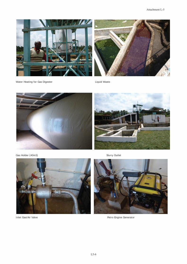
Water Heating for Gas Digester Liquid Waste
Gas Holder (40m3) Slurry Outlet
Inlet Gas/Air Valve Petro Engine Generator

Project for Establishment of Rural Electrification Model Using Renewable Energy
Sector: Biogas
Date: 28th June 2012
Organization: Biopower Systems Ltd.
Meeting Called By JICA Project Team
Type Of Meeting Information collection
List Of Attendees 1. Peter Gichohi – Biopower Systems 2. Yuka Nakagawa - Project Team 3. Aisha Abdulaziz- Project Team
Agenda 1. Company Information 2. Project Information 3. Technical Advices
SUMMARY OF DISCUSSION 1. Company Information
(1) Biopower Systems Ltd.: Mr. Peter Gichohi, 0722 620 234 [email protected] (2) Started in 2007, as a change-over from another company name. Biogas installation
experience is abundant. For generation, experiences are:2kW (Petro engine) for milking machine and chaff cutter, 4.5kW for domestic application, 16kVA for water pump, 2kW under construction for pig facility, 20 kW for a secondary school (Mang’u) and 20 kW planned for 1000 Cows farm
(3) PVC bag is durable more than 10 years. It was initially imported from Germany, and is currently imported from China. Up to 120m3 is possible. Red Mud Bag contains aluminum sludge which makes it durable against pressure.
(4) For civil work, they hire outside civil engineers and workers. (5) Permanent employees are4 (6) The company provides EIA consulting service.
2. Project Information:
(1) Murang’a Biogas Project: 80 Km from Nairobi. Funded by UNIDO. Not being successful due to feed stock, which is banana waste and requires hydrolysis process. 150 kg/day. 20m3 tank is installed. 12 kVA modified diesel engine is installed, utilizing 20% diesel and 80% biogas. The grid was also extended when the project was underway and electricity is now being used.
(2) Mang’u high school (40 km from Nairobi): REA project. 20 kW generator is installed. Feedstock is cow dung and human waste. Tender document of REA only specified the size (2 x 100m3 and 1 x 50m3), and detailed design was conducted by the manufacturer.
(3) Flower Biogas: Currently it is on-going under MoEn, with 400 m3 tank, 100 kW biogas-engine generator, expected to include CHP. EIA was conducted and license was issued.
(4) Thika: 115 m3 digester is planned with a 55 kW generator, also expected to include CHP.
3. Technical Advises (1) Generally, gas-generation efficiency is reported to be 0.5 m3/kWh. Their system
achieves more. Recommendation to use natural gas generators rather than modify. (2) Masonry/concrete tank and gas holder PVC bag is provided. SSB (1:10 cement: soil) is
traditionally applied for masonry. Recommendation to use padding as insulation in the plastic bag pit.
(3) H2S is required to be removed completely for application of biogas to generation system. They are planning to procure methane and H2S sensor to measure concentration.
(4) Utilization of modified petro-generator is possible up to 10kW. Limitation of use at

maximum 6 hours per day. At present, China manufacturer produces biogas engine generator with spark igniter, possible up to 1MW.
(5) For power production, gas holder is a must as well as H2S purification . (6) Masonry tank is possible up to 200m3. Bag digester is recommended up to 9m3. Explore
possibility of using steel tanks (experience of use over 10 years). (7) CHP is advised to circulate hot water from engine and keep the digester warm. (8) For fridge, solar heat pump is recommended for effective cooling. (9) EIA must be conducted and submitted to National Environmental Management
Authority, for any system that treats waste water. The company prepared EIA report for FS of Power Generation from Flower Waste at P.J. DAVE Flowers Ltd. The report soft copy was requested to provide to the Team.
Action Items Person Responsible
Example of EIA report for Biogas generation Mr. Peter, follow-up by Ms.Aisha
Tender document for Mang’u high school. Ms. Aisha (obtain from REA)
Attachment: Specification of gas holder bag.
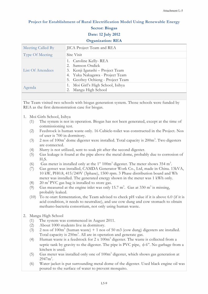
Project for Establishment of Rural Electrification Model Using Renewable Energy
Sector: Biogas
Date: 12 July 2012
Organization: REA
Meeting Called By JICA Project Team and REA
Type Of Meeting Site Visit
List Of Attendees
1. Caroline Kelly- REA 2. Samson Ondiek 3. Kenji Igarashi – Project Team 4. Yuka Nakagawa - Project Team 5. Geofrey Ochieng - Project Team
Agenda 1. Moi Girl’s High School, Isihya 2. Mangu High School
The Team visited two schools with biogas generation system. Those schools were funded by REA as the first demonstration case for biogas. 1. Moi Girls School, Isihya
(1) The system is not in operation. Biogas has not been generated, except at the time of commissioning test.
(2) Feedstock is human waste only. 16 Cubicle-toilet was constructed in the Project. Nos of user is 700 in dormitory.
(3) 2 nos of 100m3 dome digester were installed. Total capacity is 200m3. Two digesters are connected.
(4) Slurry is not utilized, sent to soak pit after the second digester. (5) Gas leakage is found at the pipe above the metal dome, probably due to corrosion of
H2S. (6) Gas meter is installed only at the 1st 100m3 digester. The meter shows 354 m3. (7) Gas genset was installed, CAMDA Generator Work Co., Ltd, made in China. 13kVA,
10 kW, PH0.8, 415/240V (3phase), 1500 rpm. 3 Phase distribution board and Wh meter was installed. The generated energy shown in the meter was 1 kWh only.
(8) 20 m3 PVC gas bag is installed to store gas. (9) Gas measured at the engine inlet was only 15.7 m3. Gas at 330 m3 is missing,
probably leaked. (10) To re-start fermentation, the Team advised to check pH value if it is above 6.0 (if it is
acid condition, it needs to neutralize), and use cow dung and cow stomach to obtain methano-bacteria consortium, not only using human waste.
2. Mangu High School (1) The system was commenced in August 2011. (2) About 1000 students live in dormitory. (3) 2 nos of 100m3 (human waste) + 1 nos of 50 m3 (cow dung) digesters are installed.
Total capacity is 250m3. All are in operation and generate gas. (4) Human waste is a feedstock for 2 x 100m3 digester. The waste is collected from a
septic tank by gravity to the digester. The pipe is PVC pipe, 6”. No garbage from a kitchen is used.
(5) Gas meter was installed only one of 100m3 digester, which shows gas generation at 2947m3.
(6) Water jacket is put surrounding metal dome of the digester. Used black engine oil was poured to the surface of water to prevent mosquito.
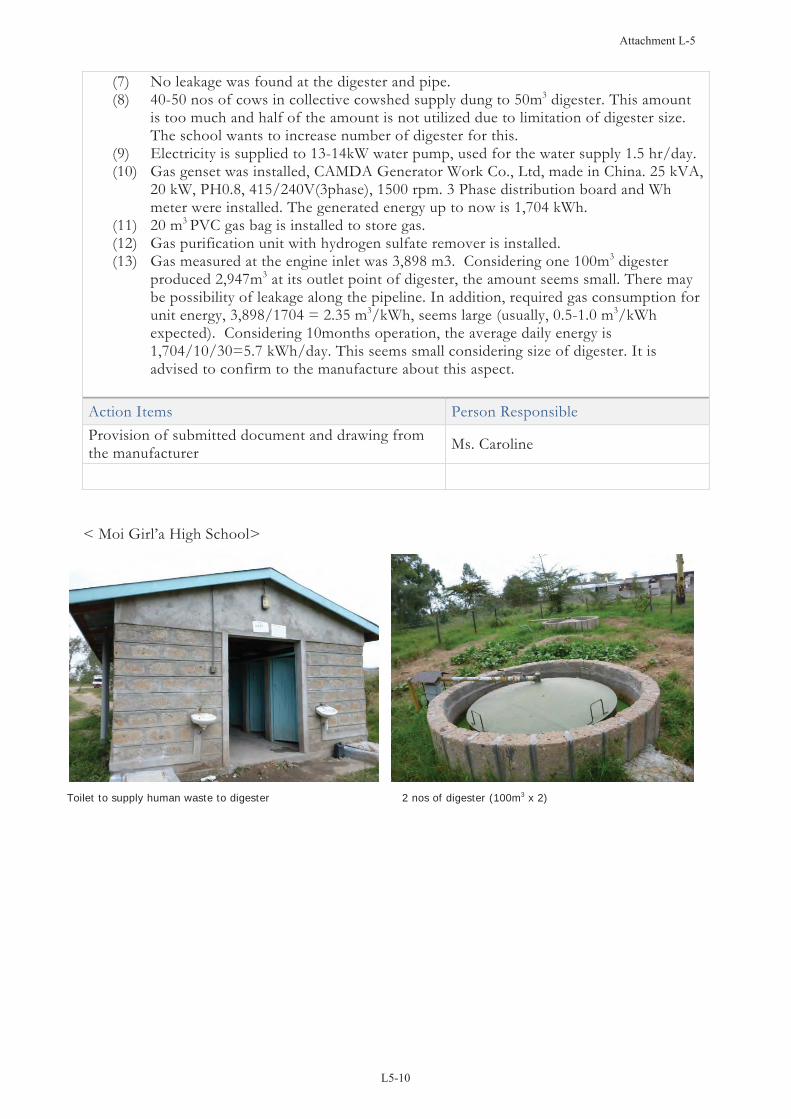
(7) No leakage was found at the digester and pipe. (8) 40-50 nos of cows in collective cowshed supply dung to 50m3 digester. This amount
is too much and half of the amount is not utilized due to limitation of digester size. The school wants to increase number of digester for this.
(9) Electricity is supplied to 13-14kW water pump, used for the water supply 1.5 hr/day. (10) Gas genset was installed, CAMDA Generator Work Co., Ltd, made in China. 25 kVA,
20 kW, PH0.8, 415/240V(3phase), 1500 rpm. 3 Phase distribution board and Wh meter were installed. The generated energy up to now is 1,704 kWh.
(11) 20 m3 PVC gas bag is installed to store gas. (12) Gas purification unit with hydrogen sulfate remover is installed. (13) Gas measured at the engine inlet was 3,898 m3. Considering one 100m3 digester
produced 2,947m3 at its outlet point of digester, the amount seems small. There may be possibility of leakage along the pipeline. In addition, required gas consumption for unit energy, 3,898/1704 = 2.35 m3/kWh, seems large (usually, 0.5-1.0 m3/kWh expected). Considering 10months operation, the average daily energy is 1,704/10/30=5.7 kWh/day. This seems small considering size of digester. It is advised to confirm to the manufacture about this aspect.
Action Items Person Responsible Provision of submitted document and drawing from the manufacturer Ms. Caroline
< Moi Girl’a High School>
Toilet to supply human waste to digester 2 nos of digester (100m3 x 2)

Gas meter at outlet of the digester Starring handle for digester
Power House for Genset and Gas Holder Biogas Engine
<Mangu High School>
Water Pump 100m3 Digester

Used engine oil to prevent mosquito Collective cow shed
Ditch for cow dung and waste connected to digester Gas purification unit
20m3 Gas holder

Project for Establishment of Rural Electrification Model Using Renewable Energy
Sector: Biogas
Date: 10 August 2012
Organization: Biogas Plant in Kilifi Sisal Plantation
Meeting Called By JICA Project Team
Type Of Meeting Information collection and meeting with community/school
List Of Attendees
1. Christopher Wilson- Director (Biogas Power Holdings (EA) Ltd. 2. Robert- Biogas Project Technician 3. Yuka Nakagawa-Project Team 4. Aisha Abdulaziz- Project Team 5. Evans Gitahi - JKUAT
Agenda 1. Site memo
SUMMARY OF DISCUSSION (1) The biogas generation plant using sisal waste and cow dung was installed in 2007 by the
Kilifi Sisal Plantations Ltd. as a private facility. It is operated by a company; the Biogas Power Holdings (EA) Ltd. The company is a joint venture between Kilifi Sisal Plantations Ltd (KE) and German companies, agri Komp GmbH and Schnell Zündstrahlmotoren AG & Co. KG. The project was established through a tripartite Public Private Partnership (PPP) with the support of GTZ.
(2) The facility sells livestock at following prices:
In calf heifers 120,000 Ksh In calf cows 110,000 Ksh Bull calves 5,000 Ksh Breeding bulls 120,000 Ksh Pregnant nanny goat 12,500 Ksh
(3) The system is grid connected, which was necessary as the installation included induction motors. However, a PPA (Power Purchase Agreement) has not yet been concluded. The initial tariff rate that KPLC offered (2007) was 2-3 USc/kWh, which was too low and was turned down by the company. At present, all the generated electricity is used for internal consumption. They are applying banking system (total energy generated in the company is deducted 7from total usage of electricity in the bill of KPLC) for electricity metering without PPA .
(4) PF (Power Factor) requirement for connection with KPLC is 0.9. The company has to pay penalties for phase-wise mismatching PF. As an example, where the PF was not matching to grid, the electricity consumption bill was 120,000 Ksh, and the additional penalty was 200,000 Ksh bringing the billing to 320,000 for the month. FIT (Feed-in-tariff) has been drafted and is awaiting approval and gazettement by government. It is hoped that this will be doneby the end of August 2012. The rate proposed by stakeholders is 12 USc/kWh.
(5) The average electricity tariff rate that the company paid to KPLC is: 10.9 Ksh/kWh in 2007, 16.2 Ksh/kWh in 2010, 23.71 Ksh/kWh in 2011, and 22.8 Ksh/kWh in 2012. 5.75 Ksh/kWh is the standard tariff (cost per Kwh exluding other billing charges such as RE) for their 3 phase category.
(6) Digester size: 750 m3, on-ground fixed dome type. Hot water from the heat exchanger at engine is circulated to maintain the temperature of digester.
(7) Installed capacity: Engine is 150 kW (75 kW x 2 units), manufactured by Brook Crompton, 2003, three phase, PF=0.87. Actual output is 90 kW. The generator is inductive type, which needs power supply from grid.

(8) Installation cost was 3,500 US$ per kW of actual output, i.e., 315,000 US$. (9) Generator: modified diesel (modification of combustion chamber, injection, and plug) (10) Annual generation amount: 200,000 kWh/year; with capacity/plans to increase to
1,200,000 kWh/year if tariffs are suitable. (11) Operation hours match the amount of gas available. The generators are operated for 36
hours continuously to exhaust available gas. A 12 hour rest period is then required for maximum gas build-up in the digester.
(12) 2 Litres per day of engine oil is consumed. (13) Capacity of motor for Sisal cutting: 100 kW. (14) 250 cows are bred in a cow shed. Cow dung is collected by a scraper with a tractor and
transported through a ditch to collection basin. Feedstock is 4 ton per day (cow dung 40% and sisal waste 60%).
(15) For removing hydrogen sulfide, filter with sieve trap and sponge is applied. The sponge is cleaned with petrol every two weeks.
Action Items Person Responsible
Sisal Material Sisal Cutting
Sisal waste used for Biogas Cow shed with 250 cows

Cow shed, collection chamber, and biogas dome Cow dung collection chamber and mixer
Biogas dome Slurry outlet for fertilizer
Diesel generator 75 kW x 2 Desulfurizing Filter

Project for Establishment of Rural Electrification Model Using Renewable Energy
Sector: Biogas
Date: 4th December 2012
Organization: JICA Project Team and Chemamit Community
Meeting Called By JICA Project Team
Type Of Meeting Meeting to inform the community of the project status (cancellation)
List Of Attendees
1. Yuka Nakagawa- Project Team 2. Aisha Abdulaziz- Project Team 3. Community members including representatives of Kiletien
secondary school and Siongiroi milk cooling facility
Agenda
1. Project Decision and Inclusion of Chemamit/Kiletien in REA’s grid extension list.
2. Project Design 3. Community Feedback
SUMMARY OF DISCUSSION Meeting with Chemamit Community 1. Project Decision and Inclusion of Chemamit/Kiletien in REA REMP The project team informed the community of the decision to cancel the project due to REA/MoEn’s targets to electrify secondary and primary schools by 2013 and 2015 respectively. The community was also informed that Kiletien secondary school and trading center had already been included in REA’s grid extension list, and rural electrification projects in the area were expected to be implemented in the short term. The project team explained that taking this into consideration, JICA decided to cancel the biogas project, despite the continuous efforts by the project team to justify the project. The community was also made aware that the decision to cancel the project was because that various other off-grid renewable energy projects in the country were not in operation as a result of grid extension, which are regarded to have failed. 2. Project Design The project team explained that the community could consider going ahead with the milk cooling business model once the village becomes electrified by grid. The community was informed of the extensive work that had been done and a synopsis of the planning report and socio-economic survey conducted was shared. It was noted that should the community decide to go ahead with developing the milk refrigeration business, the design and operations will be much simpler than indicated in the document. The project design document was handed over to the community, with the chief as custodian. 3. Community Feedback The community was disappointed by the project’s cancellation as a lot of work and discussion had been underway in preparation for project implementation. They however also appreciated the time and consideration of the team, the team’s selection of Chemamit and the follow up meetings and surveys conducted. The community also noted in reference to the project design document the amount of work that had already been completed. They requested for : - Recommendation/consideration of Chemamit for other community development projects that may come up - Assistance in procuring a milk cooler should the project team be in a position to communicate such a request to any development partners. The project team also provided clarification on the fact that since the project had been cancelled, it would not be possible to provide any technical or financial assistance in regards to
the proposed milk cooling business. 4. Conclusion from Community Meeting The requests by the community were noted, and the project team commended them on their positive consideration and support during the project development phase. It was noted that the Chemamit community is remarkable and would be recommended should the team have any other opportunity. The meeting was concluded by the project team presenting a small token of appreciation (solar lantern) to Chief. Phillip Kirui for his consistent support and mobilization of the community. 5. Meeting with Singiroi Milk Cooling Facility The project team paid a courtesy call to Mr. Ferdinand Okinyi (Manager, Siongiroi milk cooling facility) to inform him of the project cancellation and community discussion. The facility was disappointed in the project cancellation due to the high level of interest in establishing an extension office for Chemamit dairy farmers. The project team provided an overview of the project plans and highlighted information which may be useful for the cooling facility; specifically the financial analysis and dairy potential. The project team communicated the community’s interest in the milk cooling services despite the project’s cancellation. Mr. Ferdinand stated that they have a plan to install satellite cooling facility. The project team closed the meeting with a word of appreciation for the support and consideration extended by the members of the cooling facility and encouragement to continue its good work in extension of dairy services in rural Kenya.

Project for Establishment of Rural Electrification Model Using Renewable Energy
Sector: Biogas
Date: 29 October 2013
Organization: Biogas Plant in Kilifi Sisal Plantation
Type Of Meeting Site Memo
List Of Attendees
1. Mr. John K. Mania, MoE&P 2. Mr. Edwin I. Nateminya, UNDP 3. Ms. Caroline Kelly, REA 4. Ms. Yuka Nakagawa, JET
SUMMARY OF DISCUSSION (1) The flower farm has 24 ha for green house for rose cultivation and coffee plantation.
The farm is owned by Eureka Holdings. (2) The biogas plant started gas production in 21 April 2013. Design and implementation of
two pilot biogas plants were conducted using flower waste as feedstock (another pilot plant is 100 kW by Insinya Roses with 400 m3 digester). Cow dung seeding for anaerobic bacteria was conducted at the initial stage.
(3) The farm consumes electricity at 10,000-18,000 kWh/month in 2012. Tariff rate is 20.6 Ksh/kWh in average. Thus, 200,000-370,000 KSh/month was paid to Kenya Power.
(4) Flower leafs are the feed stock. The feedstock input is 300-400 kg/day. The material is homogeneously cut by a 7 kW shredder (About 2 kWh is consumed to process 300 kg feedstock).
(5) A 200 m3 anaerobic digester with concrete base and plastic gas dome is installed. It has a 5.5 hp pump for mixing.
(6) Two 8 m3 hydrolysis tanks are also installed for pre-treatment before anaerobic process. It has the same 5.5 hp pump for effluent transportation for each tank.
(7) The digester is covered by a shade to avoid rain. (8) A 55 kW biogas engine generator is installed (1500 rpm, six-cylinder 5.88 L engine,
=0.8) with a hydrogen sulfide removal unit and heat exchanger for digester heating. (9) The project cost is 206,859 US$ (3,761 US$/kW). MoE&P invested 25% and while
Eureka Holdings invested 75%. (10) Hydrolysis tank has solar water heating system. Digester is equipped with hot water
circulation system utilizing waste heat of biogas engine. Temperature of the hydrolysis tanks and the digester is monitored by thermocouples. The temperature of the digester was 27 oC
(11) Exhaust CO2 gas from engine is introduced to greenhouses to enhance plant growth. (12) Gas pipe from anaerobic digester is cooled down in a pool surrounding the digester to
trap water content in the gas. This is a good device to trap water efficiently. (13) The report says that 357 kg/day average feedstock input produces biogas of 600
m3/month gas in June 2013. This means average gas production is 20 m3/day and gas generation amount per weight of feedstock is 17.8 kg/m3.
(14) According to the log book in the power plant, the output in October 2013 is as follows:Average gas production: 16.6 m3/day Average electric energy production: 17.1 kWh/day Average gas efficiency: 1.03 kWh/m3.

Date TimeFlowm3
ExportkWh
OperationTime h:m
GasProduction
EnergykWh
EfficiencykWh/m3
11:40 2,195.4 1,903.012:35 2,201.1 1,924.411:30 2,208.6 1,926.313:00 2,216.4 1,959.3
(10/7, 10, 11, 15 operated)9:25 2,259.1 1,959.3
10:20 2,299.8 1,995.69:15 2,429.1 2,120.4
12:00 2,485.2 2,183.7(2 days in operation, date not sure)
10:04 2,527.7 2,225.711:50 2,560.8 2,263.110:10 2,560.8 2,263.912:00 2,607.1 2,318.88:50 2,560.8 2,314.2
11:10 2,660.3 2,381.0Average 16.60 17.07 1.03
5.75 21.4 3.72
1:30 7.81 33 4.23
40.66 36.3 0.89
2:45 56.11 63.3 1.13
1.19
33.15 37.4 1.13
99.48 66.8 0.67
21/10/13 1:46
46.28 54.9
1/10/13
4/10/13
?/10/13
16/10/13
28/10/13 2:20
1:50
0:55
0:55
23/10/13
(15) Compared to the initial plan of 48.6 kW operation at 8 hours/day, the current
production amount is considered to be small (48.6kW x 8h/d x PF0.4 /1.03kWh/m3=151 m3). Flower waste may require long retention time for digestion since it contains fibers which are difficult to decompose. Since the project is still at the initial stage at present, the circumstance in digester may still require a lead time for bacteria acclimation. Gas production may be increased in the later stage after the bacteria is optimized for decomposition of feedstock at optimum temperature.
Action Items Person Responsible
Feedstock rose leaves and shredder. Plastic gas dome and PVC pipe in a pool for gas cooling
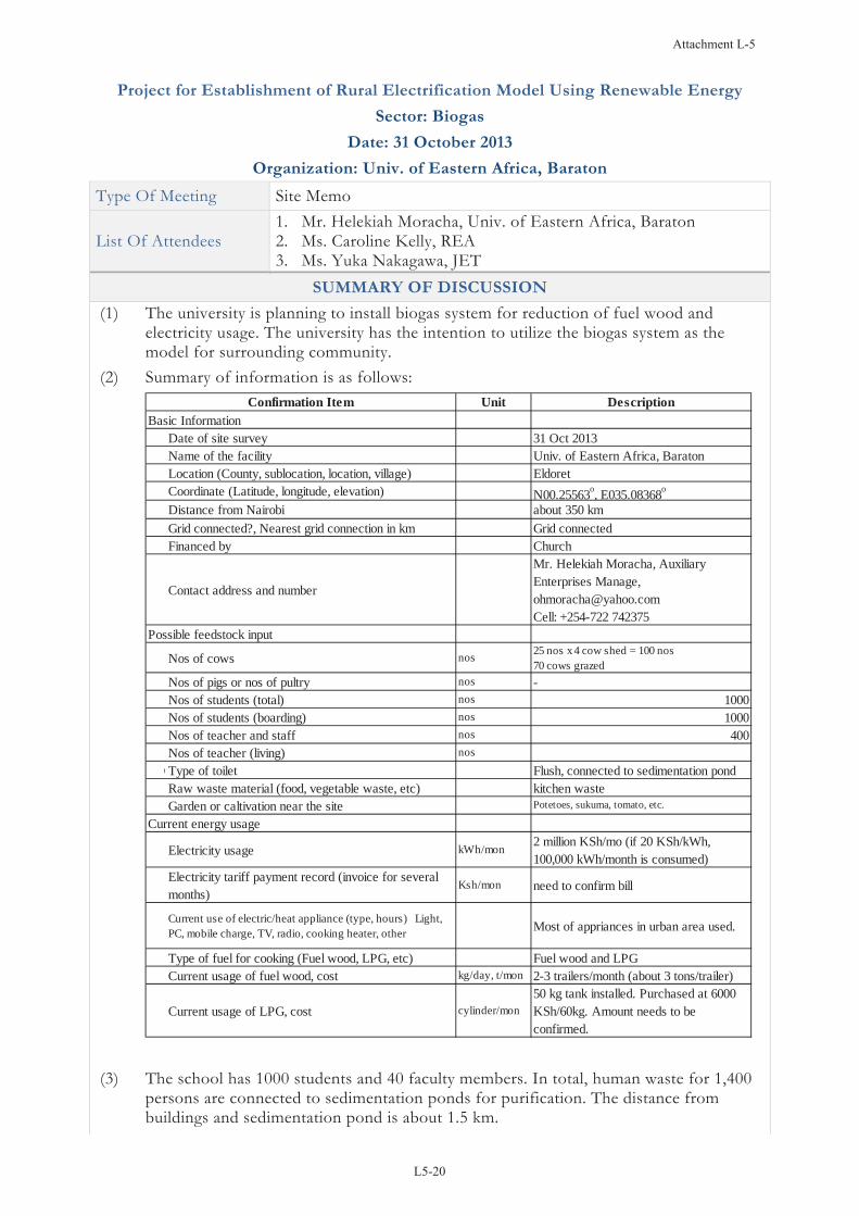
Project for Establishment of Rural Electrification Model Using Renewable Energy
Sector: Biogas
Date: 31 October 2013
Organization: Univ. of Eastern Africa, Baraton
Type Of Meeting Site Memo
List Of Attendees 1. Mr. Helekiah Moracha, Univ. of Eastern Africa, Baraton 2. Ms. Caroline Kelly, REA 3. Ms. Yuka Nakagawa, JET
SUMMARY OF DISCUSSION (1) The university is planning to install biogas system for reduction of fuel wood and
electricity usage. The university has the intention to utilize the biogas system as the model for surrounding community.
(2) Summary of information is as follows: Unit Description
Basic InformationDate of site survey 31 Oct 2013Name of the facility Univ. of Eastern Africa, BaratonLocation (County, sublocation, location, village) EldoretCoordinate (Latitude, longitude, elevation) N00.25563o, E035.08368o
Distance from Nairobi about 350 kmGrid connected?, Nearest grid connection in km Grid connectedFinanced by Church
Contact address and number
Mr. Helekiah Moracha, AuxiliaryEnterprises Manage,[email protected]: +254-722 742375
Possible feedstock input
Nos of cows nos 25 nos x 4 cow shed = 100 nos70 cows grazed
Nos of pigs or nos of pultry nos -Nos of students (total) nos 1000Nos of students (boarding) nos 1000Nos of teacher and staff nos 400Nos of teacher (living) nos
OType of toilet Flush, connected to sedimentation pondRaw waste material (food, vegetable waste, etc) kitchen wasteGarden or caltivation near the site Potetoes, sukuma, tomato, etc.
Current energy usage
Electricity usage kWh/mon 2 million KSh/mo (if 20 KSh/kWh,100,000 kWh/month is consumed)
Electricity tariff payment record (invoice for severalmonths)
Ksh/mon need to confirm bill
Current use of electric/heat appliance (type, hours) Light,PC, mobile charge, TV, radio, cooking heater, other Most of appriances in urban area used.
Type of fuel for cooking (Fuel wood, LPG, etc) Fuel wood and LPGCurrent usage of fuel wood, cost kg/day, t/mon 2-3 trailers/month (about 3 tons/trailer)
Current usage of LPG, cost cylinder/mon50 kg tank installed. Purchased at 6000KSh/60kg. Amount needs to beconfirmed.
Confirmation Item
(3) The school has 1000 students and 40 faculty members. In total, human waste for 1,400 persons are connected to sedimentation ponds for purification. The distance from buildings and sedimentation pond is about 1.5 km.

(4) It is considered that human waste in this school is not preferable to biogas digester since (i) the toilets in the school is urban type and utilize too much water, and (ii) distance from sedimentation pond is too far a way to demand center and it needs long piping and distribution lines.
(5) School cafeteria is supplied by LPG with 50 kg fuel tank. LPG is purchased at 6000 KSh per 60 kg. The amount of LPG usage needs to be confirmed in energy audit of the school. Cooking fuel supply to the cafeteria is the priority for biogas use. The cafeteria is located about 1km from cow shed.
(6) There are teacher’s quarter buildings about 300-400m from cow shed. (7) The school has four number of cow sheds. Each has 50 nos of cows. In total, 200 cows
are zero-grazed. This can be considered as the source of cow dung feedstock. It needs floor cement placement and construction of ditch for collection of cow dung to the digester. In addition, there are 70 grazed cows but this is not considered as feedstock source since collection of cow dung is necessary.
(8) Milk is processed at plant to pasteurize milk and fuelwood is consumed about 4-6 tons/month for the boiler in the plant.
(9) The available budget of the school is 600,000 KSh only. This will cover only one digester, and not sufficient for whole system. It will require additional finance source for whole system.
(10) It is not much recommended to install generator due to budget limitation and low economic feasibility electricity compared to replacement of fuel wood.
(11) The most feasible system is considered as follows: - 4 nos of 50 m3 digesters for each cow shed (or 2 nos of 100 m3 digesters for two cow sheds respectively with connecting trench construction) - 2.4 ton/day cow dung will be available as feedstock, then 72 m3/day gas production and 12.5 ton/month fuel wood saving is expected. - Boiler in milk processing plant near cow shed is the best demand in terms of distance and cost. Short pipe connection is necessary. - It is proposed about 40-50% of the gas is consumed in milk processing plant, and remaining gas is consumed in teacher’s quarter if 4 x 50 m3 (or 2 x 100m3) digester is constructed. Connection with school cafeteria needs consideration for pressure drop and cost in terms of long distance. - It is recommended to construct 1 or 2 nos of 50 m3 digester and connect with milk processing plant at the first stage, monitor the feasibility, and then, determine to whether expand the system with another digester and piping to other demand or not.
Action Items Person Responsible - Mr. Moracha will send energy audit report, electricity bill, amount of LPG consumption, and price of fuel wood to REA

Cow shed, need floor cement placement Sedimentation pond


