Embed Size (px)
Citation preview

SIMPLE PLANS FOR THE SUNKEN POT APROSTOVE
This stove was designed through the coordinated efforts of Aprovecho Research Center, GTZ, ProBEC and the people of Southern Africa. If you have questions about these plans please contact your local ProBEC representative at____________ or contact Aprovecho at [email protected]. This stove is designed for a #2 and #3 round-bottom cast iron pots. This stove can also be modified to accommodate a number of different pot sizes. The stove body can be built with 1 mm galvanized sheet steel (above left), cement, brick or 3CR12 (above right). Material price for the galvanized model in South Africa is approx 300 Rand (Summer 2002).
Photos and Text by Peter Scott Drawings by Ethan Hughes

If yes, then consider building an unvented stove outside the house. Unvented stoves can often be more efficient, easier to build, and longer lasting. If the chim-ney is not replaced when it eventually degrades, the indoor stove could expose the family to more smoke than if they had continued to cook outside with an open fire.
Are people cooking outside?
Is Liquid Petro-leum Gas (LPG) readily available?
Are they build-ing conserva-tive open fires?
Are they using flat bottom pots ?
If you answer YES to any of these questions, you should RECON-SIDER introducing the Aprostove into your community. See the next page for other designs that might be more appropriate or contact Aprovecho Research Center for more information.
If yes, than con-sider encouraging a switch to LPG. In many southern countries, wood is not sustainably har-vested so even an improved wood stove can lead to long term forest degradation. There is some evidence that LPG stoves produces less green house gases than wood fires.
If yes, consider introducing a haybox or an unvented stove outside the house. A small, carefully tended open fire can be very effi-cient. Unfortu-nately, this type of fire is uncommon in most parts of the world.
If yes, consider introducing the Ecostove or a regular Rocket outside. Flat bottom pots will not work with the Aprostove due to poor con-tact with the cooking sur-face. I f they have only one pot, consider introducing a Rocket stove.
The Aprostove’s chimney, combined with its high combustion efficiency, make it an ideal stove for people who are aware of the health and envi-
ronmental hazards of open fires. However, the Aprostove is not the ideal stove for every cooking situation.
Here are some things to consider before introducing this stove in your community:
1

Aprovecho stoves are built using principles that can be adapted to suit any cooking need. Because one stove design will not work in each community, we offer a number of stove models to choose from:
This stove - de-signed by Aprove-cho—features an insulated ceramic rocket combustion chamber. It can cook 3 pots of food, make tortil-las and bake bread. Price in Central America is approx US$ 80.
The Double Burner Rocket stove is less ex-pensive and more efficient (25 - 30%) than the Aprostove. It is ideal for cooking outside or in areas where a chimney is not needed or available.
THE ROCKET STOVE THE ECO STOVE
THE ROCKET RING STOVE
With the rings in place, mul-tiple pots can be cooked at the same time. The rings can also be re-moved for use with individ-ual round bot-tom pots.
THE HAYBOX COOKER
The haybox works by retaining heat inside a layer of insulation such as straw, wool or foam. The haybox can reduce fuel consumption by 70% and is simple and inexpensive to build .
For more information about these stoves please contact Aprovecho Research Center.
DIFFERENT STOVES FOR DIFFERENT NEEDS
2

The body of the Aprostove can be built with a variety of different materials such as cement, clay & sand, brick, adobe, or metal. This guide explains how to construct the stove with metal but other plans are available to build the Justa with cement and brick.
This cement Aprostove is being built by Helps International in the Guate-malan Highlands. Three individual cement pieces are cast in fiberglass molds and then assembled on site. The molds are easy to transport and help prevent design inconsistencies.
This brick stove –designed by Aprove-cho - has an insulated rocket combus-tion chamber. Thousands of these stoves have been built in Central America. The metal lid is removable so a single pot can be cooked with direct flame.
e
BUILDING WITH BRICK OR CEMENT
3
The type of material (cement ,brick , adobe or metal)) that is used for the exterior stove body will not have a great impact on the performance of the stove. Special materials are not needed for the stove body. The stove will function effec-tively as long as the body of the stove can support 5 pots and can withstand tempera-

BEFORE GETTING STARTED
Tools • Tin snips (offset if possible) • Electric steel grinder and cutter • Arc welder • Vice grips and/or pliers • Steel friction cutter for cutting 45° angles • Square • Metal chisel • Scribe • Metal jigsaw Optional • Hydraulic box and brake (for bending) • MIG welder • Plasma cutter
Materials • 1 sheet of 1 mm galvanized steel ) • Combustion chamber: ceramic,
3CR12 ,or mild steel • One sheet of 1225 mm by 2500 mm
1.2 mm 3CR12 • One sheet of 1225 mm by 2500 mm 2
mm steel • 10 kg of medium grade vermiculite • 6 m by 25 mm by 2 mm square tube • 6 m by 10 mm by 2 mm square tube • Stainless steel welding rods • 100 mm galvanized chimney pipe and
elbow section
BEFORE SELLING THE STOVE, YOU SHOULD ASK THE POTENTIAL BUYER A NUMBER OF QUESTIONS: What type of fuel are they using for the majority of their cooking? Wood? Fossil fuel (paraffin or LPG)? The Aprostove is suitable. Be cautious about introducing a wood stove to women who are us- ing other types of fuels as it can lead to an increase in overall wood consumption. Consider promoting a Haybox/Wonderbox instead. Does the buyer want to cook inside or outside of their house? Outside or in a well ventilated area? Inside? The Rocket stove is suitable. The Aprostove is suitable. What size pots are they using? Are they round bottomed or flat bottomed or a combination of both? Make the stove based on the cooks needs. What is the thickness of the pieces of the wood that they are using? Twigs and pieces less than 50 mm? Pieces larger than 50 mm? The 100 mm square tube diameter The 125 mm round tube diameter round rocket elbow rocket stove be used. should be used. Note: This is only a partial list of the questions that should be asked. Try to find out as much about the cooking habits of each customer before selling a stove.
4
Note: In this guide ‘O’ bends refer to outward bends or bends up from the plane of the page , whereas ‘X’ Bends refer to inward bends or bends down away from the plane of the page. Unless otherwise noted, all bends are 90 degrees
SCHEMATIC OF THE APROSTOVE
5
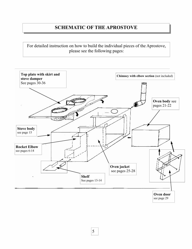
Top plate with skirt and stove damper See pages 30-36
Chimney with elbow section (not included)
Stove body see page 15
Oven jacket see pages 25-28
Oven body see pages 21-22
Rocket Elbow see pages 6-14
Oven door see page 29
Shelf See pages 13-14
For detailed instruction on how to build the individual pieces of the Aprostove, please see the following pages:

ROCKET ELBOW OPTIONS The Aprostove can be made with different types of materials. The type of elbow/combustion chamber should be chosen before building the stove body as each elbow requires a different stove body configuration. Options are listed in order of preference.
Option 2: 3CR12 1.2 mm flat sheet 3CR12 can be bent into a 100 mm rectangular box which can then be cut to form an elbow. Price (in South Africa): is approx. 30 Rand per combustion chamber. (The 3CR12 elbow shown here is the Single Pot Rocket version*).
Option 3: 100 mm by 3 mm mild steel square tube Price in South Africa: is approx 20 Rand per combustion chamber. 125 mm by 3 mm mild steel round tube can also be used . Price: in South Africa is 22 Rand per elbow.
Cast iron, refractory cement and various types of insulative ceramic (such as pumice/ vermicu-lite and clay blends can be also be used. See Rocket Design Guide for more information about the benefits and challenges of some materials. Aprovecho is presently developing a new insula-tive ceramic elbow. Contact us for more details. *Plans are also available for the Single Pot and Double Burner model.
Option 1: Ceramic Tiles Price (in Central America): is approx 10 Rand per elbow
6

From the following 5 pages, choose one of the 3 elbow options: ceramic tiles, 3CR12 or 3 mm mild
steel.
Follow the appropriate directions in the other parts of the guide which are specific to the elbow that you have
chosen. For example if using the 100 mm elbow be sure to follow the directions for the corresponding 100
mm shelf.
7

8
Cut 2 side pieces with these di-mensions
The
The top
The back
The front
115
85
135
140
250
175
75
25
250
115
165
135
135
115
175
165
75
165
ROCKET ELBOW WITH CERAMIC TILES
Use the following measurements to form a combustion chamber with ceramic bricks. Some experimentation will be necessary to create the ideal ceramic brick. The ideal bricks are not hard pressed or compacted like modern brick. They use a lot of water and are set up ‘sloppy’. This will result in a porous brick that is friable. When placed in water, it should ‘fizz’ due to the large number of pores in the brick. The tiles should not feel dense or heavy but crumbly and soft. The ideal thickness is 25 mm. See Rocket Design Guide for more info.

BUILDING THE COMBUSTION CHAMBER WITH 1.2 MM 3CR12
1225
2500
408.3
408.3
408.3
400 400 400 400 400
Scribe and cut the 1225 mm by 2500 mm piece as shown below to yield 15 elbows.
100 100 100 100 8
400
Take each piece and scribe the lines as shown but do not cut . Bend the 4 scribed lines to form a 4 -sided box with an 8 mm lip. See following page for a sketch of how the box should ap-
Take one piece of 1225 mm by 2500 mm by 1.2 mm 3CR12.
9
400 100

100 mm Take the 400 mm by 100 mm section.
Cut a 45 degree angle as shown.
Lift section ‘A’ 90 degrees on the vertical and rotate 180 degrees.
Connect the two pieces and tack weld along the seam. Make sure there are no gaps along the seam that could allow insula-tion to fall through.
400
100
Before welding the two pieces together, grind the insides of the joints smooth. If sharp pieces are left exposed then the stove users could cut their hands when they reach in to the combus-tion chamber to clean out the wood ash .
COMPLETING THE 100 MM 3CR12 COMBUSTION CHAMBER
The 3CR12 rectangular box from the previous page should look like this.
10

10Take one piece of 100 mm by 6 metre square tube and cut a 400 mm section.
Cut a 45 degree angle as shown.
Before welding the two pieces together, grind the insides of the joints until smooth. If sharp pieces are left exposed on the inside of the tube, the cook could cut their hands when they reach in to clean out the wood ash. Build two complete combustion chambers as shown.
CONSTRUCTING THE 100 MM SQUARE TUBE ROCKET ELBOW
Lift ‘A’ section 90 degrees on the vertical and rotate 180 degrees.
Connect the two pieces and tack weld along the seam. Be sure to fill in any gaps between the pieces that might allow insulation to pass through.
11
400
150 250
Weld
250 150
45°
A B
A
B

Take one piece of 125 mm by 6m round tube and cut one 375 mm section.
Cut a 45 degree angle as shown.
Lift section A 90 degrees on the vertical and rotate 180 degrees.
Connect the two pieces and tack weld along the seam. Be sure to fill in any gaps that might allow insulation to pass through.
Before welding the two pieces together, grind the insides of the joints smooth. If sharp pieces are left exposed the cook could cut their hands when they reach in to clean out the wood ash.
BUILDING THE 125 MM BY 3MM ROUND TUBE ROCKET ELBOW
12
125 mm

BUILDING THE SHELF FOR THE 100 MM COMBUSTION CHAMBER
( Use 2 or 3 mm mild steel or 1.2 mm 3CR12)
140
90
150
200
Cut one piece of mild steel or 3CR12 into a 200 mm by 140 mm section.
90
150
Scribe but do not cut the dotted lines as shown.
Cut the two 25 mm dotted lines.
90
Fold along the two dotted lines to form the 25 mm shelf supports.
25
25
25
25
25
25
13

Building the shelf for the 125 mm mild steel round tube combustion chamber
BUILDING THE SHELF FOR THE 125 MM ROUND TUBE ROCKET ELBOW
Use 2 or 3 mm mild steel or 1.2 mm 3CR12)
130
110
150
200
Cut one piece of 200 mm by 130 mm 3 mm mild steel or 1.2 mm 3CR12.
110
150
Scribe the dotted lines as shown.
Cut along the dotted lines and remove the two 10 mm by 250 mm sections.
110 The shelf should be T-shape upon completion.
10
10
10
10
14
10
10

Front panel see page 17
CONSTRUCTING THE APROSTOVE BODY
Side panel ‘B’ see page 23
Back panel (chimney exit) see page 18
Box bottom see page 19
Side panel ‘A’ (elbow entrance) see page 19
15
For detailed instruction on how to build the individual pieces of the stove body, please see the following pages:

SCRIBING THE INDIVIDUAL STOVE BODY PANELS
Side panel
Side panel 612
612
Front Panel
Back Panel
Bottom
405
405
400
425
640 425
For the top plate use 2 mm ungalvanized plate steel.
650
408
408
408
16

405 405
BUILDING THE BODY OF THE ECOSTOVE (For 100 mm Rocket Elbow)
The Front Panel for Rocket Elbow entrance.
425
1 Take a piece of 1 mm galvanized sheet steel and cut one piece 425 mm by 405 mm.
425
2 Take the rocket elbow and center it 50 mm from the bottom of the sheet and scribe a line around its 100 mm perimeter.
50
3 Scribe and cut a line 5 mm inset from the previ-ous 100 mm scribe line. ‘O’ Bend the 5 mm flange to fit the perimeter of the combustion chamber.
100
95
4 Scribe two 25 mm lines along the 425 mm sides and then ‘O’ Bend.
25 25 355
425
405
17
BUILDING THE BODY OF THE ECOSTOVE
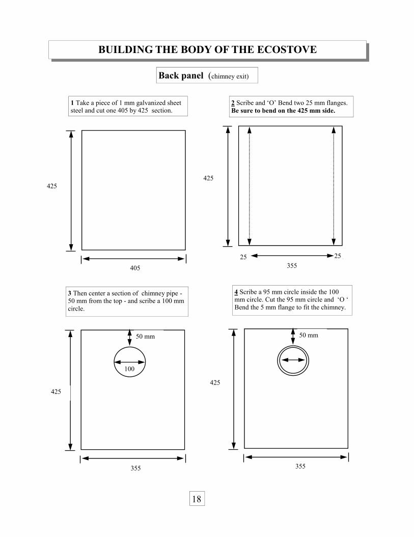
Back panel (chimney exit)
1 Take a piece of 1 mm galvanized sheet steel and cut one 405 by 425 section.
2 Scribe and ‘O’ Bend two 25 mm flanges. Be sure to bend on the 425 mm side.
3 Then center a section of chimney pipe - 50 mm from the top - and scribe a 100 mm circle.
4 Scribe a 95 mm circle inside the 100 mm circle. Cut the 95 mm circle and ‘O ‘ Bend the 5 mm flange to fit the chimney.
425
405
25 25 355
425
50 mm
100
425
50 mm
425
355 355
18 18

BUILDING THE BODY OF THE ECOSTOVE Side panel ‘A’ and Bottom panel
425
612
5
5
425
602
1 Take a piece of 1 mm galvanized sheet metal and cut one section 612 mm by 425 mm
2 ‘O’ Bend two 5 mm flanges.
Box bottom Take one piece of 1 mm galvanized sheet steel and cut one section 640 mm by 400 mm
640
400
Remove a 25 mm tab from each corner and then fold to form four lips.
Side Panel ‘A’
590
350
19

CONSTRUCTING THE BOX
Join the front panel and the Back panel to the outside of the box bottom. Drill 5 holes where each panel meet but attach only 2 screws per side.
Then attach side panel ‘A’ to the outside of the Back and the Front panels. Drill 5 holes where each panel meet but attach only 2 screws per side.
Side Panel ‘A’ Back panel
Bottom Panel
Front panel
20

CONSTRUCTING THE OVEN
Take a piece of 1.2 mm 3CR12 and cut one section 879 by 330 mm.
330
879
Scribe the lines as shown and then fold into a 4 sided box with a 25 mm lip. Weld with stainless steel welding rods. Before welding , double check that the 4 sides are exactly 25, 197, 230, 197, and 230.
197 230 197 230 25
fold
21

CUTTING THE OVEN BOTTOM
192
1 Cut one piece of 1.2 mm 3CR12 242 mm by 275 mm.
242
275 225
2 Remove a 25 mm tab from each corner and fold the sides to form the four lips of the oven bottom.
3 Insert the oven bottom into the inside of the oven box and tack weld with stainless steel welding rods.
22

CUTTING SIDE PANEL ‘B’ (OVEN ENTRANCE)
425
612
1 Take one piece of 1 mm galvanized sheet steel and cut a 612 by 425 mm section.
425
612
2 Place the completed oven unit on the top right corner of the sheet—75 mm from the bottom and 55 mm from the side. Scribe but do not cut a line around the oven body.
55
75
3 Scribe another box , inset 25 mm in from the previous box. Cut out the inset box.
425
612
55
75
4 X’ Bend two 5 m flanges (bending down away from the planes of page).
425
602
5
5
Cut and remove
23

COMPLETING THE OVEN ENTRANCE
24
425
602
Cut four 25 mm lines on a 45 degree angle to form the four flanges . ’O’ bend these flanges (bending up and out ward from the plane of the page).
Side panel ‘B’
Once the oven entrance is cut, attach side panel ’B’ to the outside of the Front panel, Back panel and the Bottom panel Drill and attach with metal screws.

BUILDING THE OVEN JACKET
Take one piece of 1 mm galvanized sheet steel or 1.2 mm 3CR12 and cut an 888 by 392 mm section.
392
80 225 283 225 75
62
25
888
Scribe the lines shown below.
25

BUILDING THE OVEN JACKET (CONTINUED)
Cut 2 miter joints and 6 straight cuts along the dotted lines. Make the straight cuts from the edge of the sheet only to the first horizontal line. Do not cut beyond the horizontal line.
62 62 62 62
cut
Cut and remove
Cut and remove
cut cut cut cut
cut 62 62
25 25 25 25
Make an ‘0’ crease* along the 62 mm dotted horizontal line and then make an ‘X’ crease* along the 25 mm dotted horizontal line. DO NOT FOLD.
62 62 62 62
62
25
*To make a crease , bend to 20 degrees and then flatten to remove the fold . When finished, the piece will lay flat with a small indentation
26
BUILDING THE OVEN JACKET (CONTINUED)
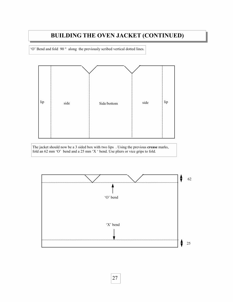
‘O’ Bend and fold 90 ° along the previously scribed vertical dotted lines.
The jacket should now be a 3 sided box with two lips . Using the previous crease marks, fold an 62 mm ‘O’ bend and a 25 mm ‘X ‘ bend. Use pliers or vice grips to fold.
‘O’ bend
‘X’ bend
62
25
lip side side lip Side/bottom
27

BUILDING THE OVEN JACKET (CONTINUED)
Once folded, the oven jacket should look like the drawing below. Note that the folds at the back of the skirt are opposite to folds at the front of the jacket (‘X’ Bends vs. ’O’ Bends)
Place the oven jacket into the stove body and then slide the oven into Side panel ‘B’/oven entrance.
Use an arc welder to weld the jacket to the oven and the jacket to the stove body. The gap between the oven body and the jacket is important. See below for the proper gap on each side.
‘O’ Bend
‘X’ Bend
65 mm between front of oven body and oven jacket.
25 mm between the bottom of the oven body and the oven jacket.
40 mm between the back of the oven and the oven jacket
28

BUILDING THE OVEN DOOR
Internal door compartment . This piece is designed to fit inside the oven. 1 Take 1 piece of 1.2 mm 3CR12 and cut a 273 mm by 225 mm section.
273
240
2 Remove a 25 mm tab from each corner and then fold to form four lips.
223
190
External door compartment This piece should fit snugly on the outside of the oven. 1 Take one piece of 3CR12 and cut a 265 mm by 298 mm section.
298
265
2 Remove a 25 mm tab from each corner and then fold to form four lips
248
215
Internal com-partment (fill with vermiculite)
External compartment
Fill the inside of the internal compartment with vermicu-lite or fiberglass insulation . Then weld the internal com-partment to the inside of the external compartment. ( note: Be sure that the internal compartment fits into the oven before welding together).
Then make a handle to your own specifications and at-tach to the outside of the external compartment.
29

CONSTRUCTING THE TOP PLATE /COOKING SURFACE
These measurement are for a #2 and a #3 round-bottom cast iron pots. The stove can be modified to accept larger and smaller size pots
408
650
Scribe the large circle - 178 mm from the edge. Scribe the smaller circle -169 mm from the opposite edge. Use a jig saw or plasma cutter to cut the two circles. Try to cut the circles cleanly so that the remaining pieces can be reused as stove lids.
178
143
169
134
Take a piece of 2 mm mild steel and cut one 408 mm by 650 mm section.
Remove four 20 mm square tabs from each cor-ner and then fold.
30

CONSTRUCTING THE TOP PLATE /COOKING SURFACE Cont’d
Take a piece of 2 mm by 10 mm square tubing and cut an 866 mm section and an 810 mm section.
Bend each section into a circular ring and weld.
866
10
10 810
Once attached to the top plate, one half (or 5 mm) of the tubing should be visible from above. The exposed part of the square tube will form a lip that will support the stove lids. The stove lids can be used to seal the stove when the pots are not in place. This will keep smoke from entering the house.
Stove lids
Take the top plate that you cut on the pre-vious page and clamp it to the welding ta-ble (to prevent warping). Then tack weld the square tube rings to the underside of the top plate. note: although the drawing adjacent only shows one ring, be sure to attach both the front and the back ring. At-tach the 275 mm ring under the large hole and the 256 mm ring under the smaller hole.
Top plate
31
275 256
Square tube ring

CUTTING AND INSTALLING THE POT SKIRT
Take one piece of 1.2 mm 3CR12 and cut a 150 mm by 1350 mm section .
1350
150
Find the center of the sheet and cut along the 100 mm vertical line and the 150 mm horizontal line.
100
150
Use a clamp to attach the top plate to a welding table (to prevent warping). Place the skirt so that the ‘X’ Bends lay behind the smaller ring (the opening for the chimney exit). Tack weld the skirt around the outside of the 10 mm square tube rings as shown in the adjacent picture. See next page for more info about placing the skirt on the top plate.
25 25 50 50
Make two 25 mm ‘X’ Bends and two 50 mm ‘X’ Bends to form the passage to the chimney exit.
32
Larger opening for #3 size pot
Bottom view of Top plate
Weld the bot-tom of the skirt to the underside of the top plate.
Smaller opening for #2 size pot

COMPLETING THE TOP PLATE ( Use 2 mm mild steel)
It is important to maintain a 150 mm gap between the two sides of the skirt to allow sufficient airflow between the first and the second pot. The 150 mm gap between the two sides of the skirt is the same dimension that will be scribed on the oven jacket to create the opening for the jacket entrance and exit.
150
150
B
A
33
Cutting the openings into the oven jacket. 1 Oven Jacket entrance Place the top plate/skirt unit on top of the stove body and A) scribe two lines where the bottom of the skirt meets the oven jacket. Then B) draw a third line joining the first two lines at the front of the oven jacket . Using an electric grinder cut these three lines. 2 Oven jacket exit Repeat step A at the back of the oven exit. Then draw a third line joining the first two lines at the back of the oven jacket.
150
2

COMPLETING THE TOP PLATE ( Use 2-3 mm mild steel or 1.2 mm 3CR12)
1 After cutting the three lines, bend the piece upwards to create a vertical flange. As shown in the drawing below. 2 Repeat at the back of the oven to form the jacket exit.
200
30
200
30
Constructing the damper. 1 Take a piece of 1.2 mm 3CR12 and cut two 30 mm by 200 mm sections.
10 10 10
2 Scribe two 10 mm lines and then make two ‘O’ folds to form a three sided ‘track’ that will serve as the guide for the damper. Repeat for both pieces.
Place the top plate on the stove body so that the tracks enter into the oven jacket. Weld the ‘tracks’ to the inside of the skirt. The tracks should lay as close to the oven body as possible.
34
Tracks
1
2

)CONSTRUCTING THE OVEN DAMPER ( Use 2-3 mm mild steel
1 Take a 7 mm steel bar and cut two 300 mm sections. These bars are the rails of the damper.
300
2 Take a piece of 2 mm plate steel and cut a 130 mm by 150 mm section
150
130
3 Weld the rails to the outside of the 2 mm steel plate.
A Drill two 10 mm holes in the top plate and slide the rails of the damper through them. The damper should: • slide smoothly in the tracks • sit inside the track guides • lay as close to the oven body as possible When the damper is in place, there should be a 50-65 mm gap between it and the front of the oven jacket. When the damper is in the lowered position it should create a 130 mm by 100 mm passage be-tween the first and second pot.
35
A
CONSTRUCTING THE OVEN DAMPER Constructing the damper handle
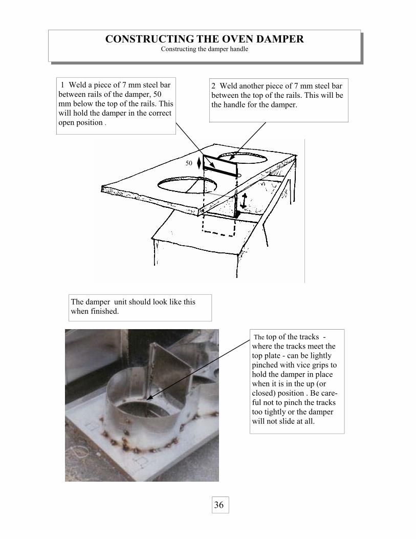
The top of the tracks - where the tracks meet the top plate - can be lightly pinched with vice grips to hold the damper in place when it is in the up (or closed) position . Be care-ful not to pinch the tracks too tightly or the damper will not slide at all.
36
50
The damper unit should look like this when finished.
1 Weld a piece of 7 mm steel bar between rails of the damper, 50 mm below the top of the rails. This will hold the damper in the correct open position .
2 Weld another piece of 7 mm steel bar between the top of the rails. This will be the handle for the damper.

FINISHING THE STOVE
Fill the stove with medium grade vermiculite or wood ash (see arrows in diagram below). Fill under and around the Rocket Elbow. Fill under and around the oven jacket. Be sure to not put any vermiculite between the oven jacket and the oven body as it will block the passage of heat around the oven. Fiberglass insulation can also be added between the skirt and the stove body.
Once the stove body is filled with insula-tion then the top plate can be perma-nently affixed to the body of the stove. Drill 4 holes per side and connect with metal screws.
Insulation should also be added on top of the oven unit (between the . The two flanges that were cut and formed on page 34 should hold the insulation in place and stop it from falling down into the oven compart-ment.
The diagram on the right shows the damper in the lowered or open position This allows hot gases to pass to the first and second pot but not the oven . When the damper is in the raised or closed position it allows hot gases to travel past the first pot and enter the oven but not the second pot . For the oven to work either both pots or stove lids must be in place to maintain sufficient draft.
37


![[Challenge:Future] Quest for Sunken Bell](https://img.dokumen.tips/doc/110x75/58f090031a28ab0a498b46b1/challengefuture-quest-for-sunken-bell.jpg)