Embed Size (px)
Citation preview

Simple Optical Network Architectures Point to Point Link
The simplest optical communication system is that linking two points. The length of such links may be a small as 100 m for say, a computer data link or as long as 10,000 km for an intercontinental communication cable.Long links are certain to be affected by optical loss and dispersion. Hence, some form of repeater must be inserted to boost the signal.If the signal only needs to be amplified then either a non-regenerative optoelectronic repeater or an optical amplifier may be used. A non-regenerative optoelectronic repeater consists of an optical detector, electronic amplifier and optical transmitter.If the quality has deteriorated unacceptably, a regenerative optoelectronic repeater, in which the signal is detected, fully demodulated, error corrected and then re-modulated and re-transmitted, can be used.

Simple Optical Network ArchitecturesPoint to Point Link
Figure below shows an amplifier based on an erbium doped optical fibre.
The erbium doped fibre amplifier (EDFA) is spliced into the existing fibre between a pair of wavelength division multiplexers. These allow optical power from the signal fibre (at 1525-1565nm) to pass through the amplifier at the same time as optical power from the one or two pump lasers (at 980 or 1480nm). Consequently, the optically pumped erbium fibre provides an optical gain medium which amplifies the optical signal as it passes through. The two isolators ensure that only the signal wavelength is transmitted onto the communication channel fibre. The EDFA introduces an additional noise component, primarily shot noise. Its noise figure is at least 3dB, however, the gain can be as high as 54dB, though 25 -30dB is more usual.
Input Signal Isolator
Pump Laser,
λ = 980 or 1480nm
IsolatorAmplified
Output Signal
WDM WDMErbium-doped
fibreλ = 1550nm λ = 1550nm
Pump Laser,
λ = 980 or 1480nm
Joint Joint

Simple Optical Network ArchitecturesBroadcast and Distribution Networks
Broadcast and distribution networks supply information to a number of subscribers simultaneously. Examples include local-loop telecommunication service networks, cable television networks and broadband ISDN networks. The length of individual links is usually less than 50km but bit rates can be up to 10 Gbs-1. The most common network architectures are
Hub Topology.
Bus Topology.
Ring Topology.
Star Topology.

Simple Optical Network ArchitecturesBroadcast and Distribution Networks
Hub TopologyFigure below shows a generalised hub topology network.
The hubs are automated switches and distribution is achieved via switching in the electrical domain. Consider, for example, the public service telephone network. Each hub serves a set of subscribers and has individual point to point links to them. There are higher bandwidth point to point links between the hubs which form a tree structure backed up by additional inter-hub links to re-route following a network fault.
Hub 1
Hub 2
Hub3
Hub4
Additional point-to-point back-up link
S11
S1n
S21S22
S41
S42
S4n
S31
S32
Fibre links to subscribers
and other hubs

Simple Optical Network ArchitecturesBroadcast and Distribution Networks
Bus TopologyFigure below shows a generalised bus topology network.
The bus is a high bandwidth optical fibre which traverses the entire distribution area. Fractions of the optical power on the bus are tapped off to provide a signal to each subscriber.
Input Power, P
1
2
3
n-1
n
NP
Fibre taps
Fibre Bus
Subscribers
nin

Simple Optical Network ArchitecturesBroadcast and Distribution Networks
Bus TopologyThe topology as shown is used in, for example, receive only cable television distribution. Evolutions of this topology permitting subscriber transmission as well as reception are used in, for example, optical ethernet LANs. In the latter, the number of subscribers is limited by the signal power available at the most distant subscriber. Each fibre tap is a directional coupler which removes a power fraction, C, from the fibre (say 5% or C=0.05). There is a loss factor, δ, associated with each tap (say a further 5%, δ=0.05). The optical power received at the nth subscriber, Pn, is therefore :
where PT is the optical power originally launched onto the bus. This simple analysis ignores any contribution from the fibre loss. Over short distances (<1km) this can be assumed to be negligible.
( ) ( ) 111 −−−= nnTn CCPP δ

Simple Optical Network ArchitecturesBroadcast and Distribution Networks
Ring TopologyFigure below shows a generalised ring topology LAN.
The ring is formed from high bandwidth optical fibres forming point to point links between nodes. Each node represents the access point for a single subscriber and consists of a transceiver. The individual links are short and so fibre loss is unimportant. An example of a ring topology optical LAN is the fibre distributed data interface (FDDI). The transceivers act as repeaters on the ring passing predefined bit streams (tokens) around while ‘listening for their unique address to receive data or appending data to ‘empty’ tokens when transmitting. The most common implementation of 100Mbs-1 FDDI uses 1.3µm LED sources and multimode optical fibre. It is used in campus networks (including at Brunel) as a backbone to interconnect LANs and/or mainframe computers.

Simple Optical Network ArchitecturesBroadcast and Distribution Networks
Star TopologyFigure below shows a generalised star topology LAN.
Subscribers transceiver nodes are connected via point to point links to the central star which is similar to an individual hub except that the signals are made available at all nodes rather than being routed to individual subscribers via a switch. The star may be active or passive. In an active star the incoming signal is opto-electronically converted into the electrical domain and then distributed to each node transmitter. In a passive star the distribution occurs in the optical domain via a passive star NxN coupler.

Sonet/SDHWith the advent of fibre optic transmission lines, the next step in the evolution of the digital time-division-multiplexing (TDM) scheme was a standard signal format called synchronous optical network (SONET) in North America and synchronous digital hierarchy (SDH) in other parts of the world.In the mid-1980s, several service providers in the USA started efforts on developing a standard that would allow network engineers to interconnect fibre optic transmission equipment from various vendors through multiple-owner trunking networks. This soon grew into an international activity, which resulted in a series of ANSI T1.105 standards for SONET and a series of ITU-T recommendations for SDH.
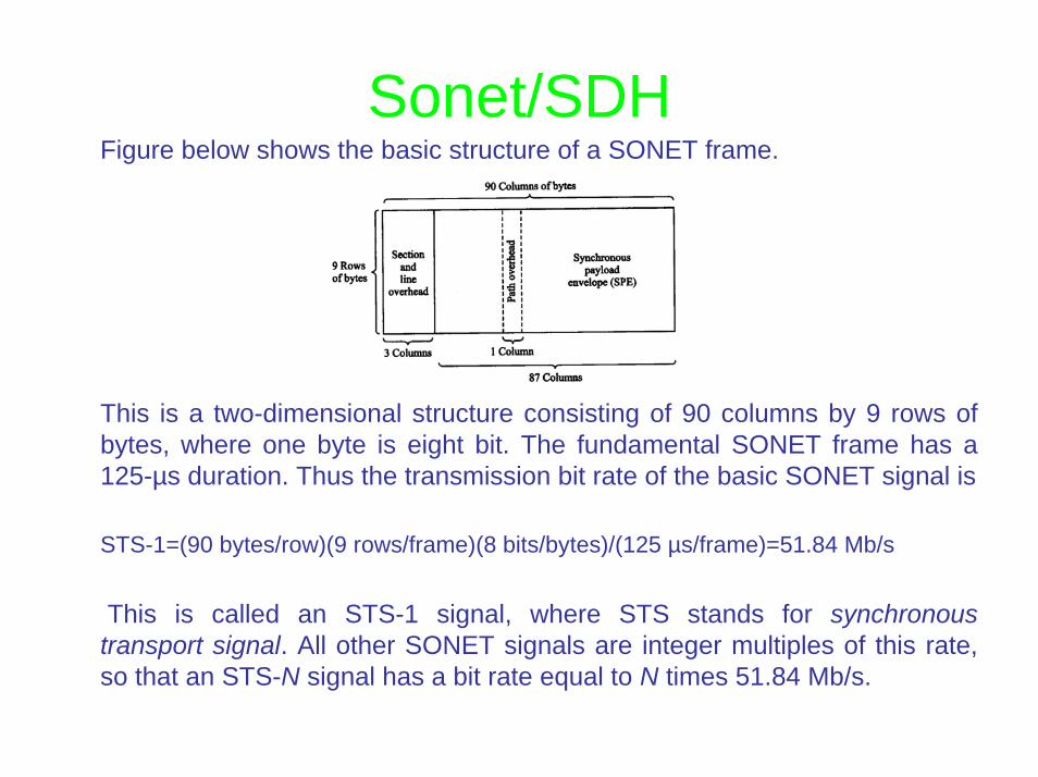
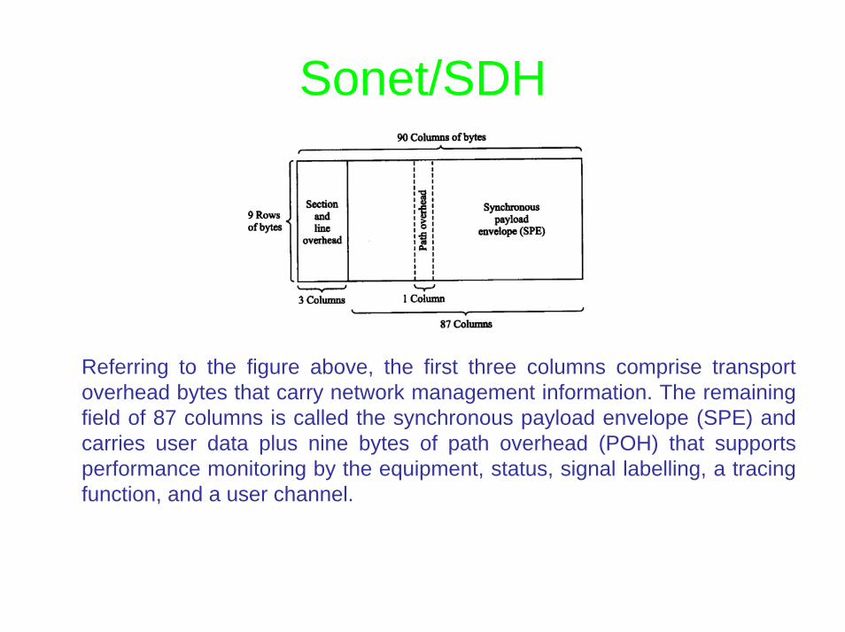
Sonet/SDHFigure below shows the basic structure of a SONET frame.
This is a two-dimensional structure consisting of 90 columns by 9 rows of bytes, where one byte is eight bit. The fundamental SONET frame has a 125-µs duration. Thus the transmission bit rate of the basic SONET signal is
STS-1=(90 bytes/row)(9 rows/frame)(8 bits/bytes)/(125 µs/frame)=51.84 Mb/s
This is called an STS-1 signal, where STS stands for synchronous transport signal. All other SONET signals are integer multiples of this rate, so that an STS-N signal has a bit rate equal to N times 51.84 Mb/s.
Sonet/SDH
Referring to the figure above, the first three columns comprise transport overhead bytes that carry network management information. The remaining field of 87 columns is called the synchronous payload envelope (SPE) and carries user data plus nine bytes of path overhead (POH) that supports performance monitoring by the equipment, status, signal labelling, a tracing function, and a user channel.

Sonet/SDHFor values of N greater than 1, the columns of the frame become N times wider, with the number of rows remaining at 9, as shown in figure below.

SONET HierarchyOptical Level
Electrical Level
Line Rate (Mbps)
Payload Rate (Mbps)
Overhead Rate (Mbps)
SDH Equivalent
OC-1 STS-1 51.840 50.112 1.728 -
OC-3 STS-3 155.520 150.336 5.184 STM-1
OC-9 STS-9 466.560 451.008 15.552 STM-3
OC-12 STS-12 622.080 601.344 20.736 STM-4
OC-18 STS-18 933.120 902.016 31.104 STM-6
OC-24 STS-24 1244.160 1202.688 41.472 STM-8
OC-36 STS-36 1866.240 1804.032 62.208 STM-13
OC-48 STS-48 2488.320 2405.376 82.944 STM-16
OC-96 STS-96 4976.640 4810.752 165.888 STM-32
OC-192 STS-192 9953.280 9621.504 331.776 STM-64
OC-768 STS-768 39818.120 38486.016 1327.104 STM-256OC-9, OC-18, OC-24, OC-36, OC-96 are considered orphaned rates.

Further Resources• http://www.tek.com/Measurement/cgi-
bin/framed.pl?Document=/Measurement/App_Notes/SONET/&FrameSet=optical
• http://www.innocor.com/pdf_files/g709_tutorial.pdf• http://www.sonet.com/EDU/edu.htm

SolitonsGroup velocity dispersion (GVD) causes most pulses to broaden in time as they propagate through an optical fibre. However, a particular pulse shape known as soliton takes advantage of nonlinear effects in silica, particularly self-phase modulation (SPM) resulting from the Kerr nonlinearity, to overcome the pulse-broadening effects of GVD.The term soliton refers to special kinds of waves that can propagate undistorted over long distances and remain unaffected after collisions with each other. In an optical communication system, solitons are very narrow, high-intensity optical pulses that retain their shape through the interaction of balancing pulse dispersion with the nonlinear properties of an optical fibre.Depending on the particular shape chosen, the pulse either does not change its shape as it propagates, or it undergoes periodically repeating changes in shape.. The family of pulses that do not chenge in shape are called fundamental solitons, and those that undergo periodic shape changes are called high-order solitons.

SolitonsSoliton Pulses
No optical pulse is monochromatic, since it excites a spectrum of frequencies. This is important, because in an actual fibre a pulse is affected by both the GVD and the Kerr nonlinearity. Since the medium is dispersive, the pulse width will spread in time with increasing distance along the fibre owing to GVD. When such a pulse traverses a medium with a positive GDV parameter for the constituent frequencies, the leading part of the pulse is shifted toward a longer wavelength (lower frequency), so that the speed in that portion increases. Conversely, in the trailing half, the frequency rises so the speed decreases. Consequently, the energy in the centre of the pulse is dispersed to either side, and the pulse eventually takes on a rectangular-wave shape. Figure below illustrate these intensity changes as the pulse travels along such fibre.

SolitonsSoliton Pulses
On the other hand, when a narrow high-intensity pulse traverses a medium with a negative GVD parameter for the constituent frequencies, GVD counteracts the chirp produced by SPM. Now, GVD retards low frequencies in the front end of the pulse and advances the high frequencies at the back. The result is that the high-intensity sharply peaked soliton pulse changes neither its shape nor its spectrum as it travels along the fibre. Figure below illustrate this for a fundamental soliton.

Ultrahigh capacity networksA major challenge in devising new optical communication systems has been the desire to fully exploit the enormous bandwidth of at least 25 THz that optical fibre channel can provide.
Advances in very dense WDM technology, ultrafast optical TDM, and the creation of clever techniques for mitigating signal impairments have already allowed transfer rate in excess of 1 Tb/s to be achieved on a single fibre.
In addition to using dense WDM techniques to increase the capacity of long-haul transmission links, ultrafast optical TDM schemes have been devised. These are particularly attractive in local-area networks (LANs) or metropolitan-area networks (MANs). In particular, researchers have examined the application of 100 Gb/s optical TDM schemes to shared-media local networks

Ultrahigh capacity networksTwo candidates methods are
Bit-interleaved TDM.
Time-slotted TDM.
Although these two techniques and WDM are identical at some level of mathematical abstraction, they are very different in practical applications.

Ultrahigh capacity networksUltrahigh Capacity WDM Systems
Higher and higher capacities are continually being demonstrated in dense WDM systems. Two approaches are popular for achieving these increased capacities. The first is to widen the spectral bandwidth of EDFAs from 30 to 80 nm. In conventional optical amplifiers, this bandwidth ranges from 1530 to 1560 nm, whereas by using broadening techniques the usable EDFA bandwidth can cover 1530-to-1610 nm range. Thus, the number of wavelengths that can be sent through the system increases greatly.The second method is to improve the spectral efficiency of the WDM signals. This will increase the total transmission capacity independent of any expansion of the EDFA bandwidth.Most of the demonstrations use a rate of 20 Gb/s for each individual wavelength in order to avoid nonlinear effects. Two examples are as follow
A 50-channel WDM system operating at an aggregated 1 Tb/s rate over 600 km link.A 132 channel WDM system operating at an aggregated 2.6 Tb/s rate over 120 Km link.

Ultrahigh capacity networksBit-Interleaved Optical TDM
Bit-interleaved TDM is similar to WDM in that the access nodes share many small channels operating at a peak rate that is a fraction of the media rate. Figure below illustrates the basic concept of point-to-point transmission using bit-interleaved optical TDM.
A laser source produces a regular stream of very narrow return-to-zero optical pulses at a repetition rate B (typically from 2.5 to 10 Gb/s). An optical splitter divides the pulse train into N separate streams. Each of these channel is then individually modulated by an electrical tributary data source at a bit rate B. The modulated outputs are delayed individually by different fractions of the clock period, and are then interleaved through an optical combiner to produce an aggregate bit rate of NxB.

Ultrahigh capacity networksBit-Interleaved Optical TDM
At the receiving end, the aggregate pulse stream is demultiplexed into the original N independent data channels for further signal processing. In this technique, a clock-recovery mechanism operating at the base bit rate B is required at the receiver to drive and synchronise the demultiplexer.

Ultrahigh capacity networksTime-Slotted Optical TDM
In time-slotted TDM, the access nodes share one fast channel, which is capable of sending burst rates of 100 Gb/s. The most important features of time-slotted TDM networks are
To provide a backbone to interconnect high-speed networks.To transfer quickly very large data blocks.To switch large aggregation of traffic.To provide both high-rate and low-rate access to users.
These types of networks can provide truly flexible bandwidth-on-demand services in a local environment for bursty users that may operate at speeds ranging from 10 to 100 Gb/s, as well as accommodating aggregates of lower-speed users. High-end customers include high-speed video servers, terabyte media banks, and supercomputers.

Ultrahigh capacity networksTime-Slotted Optical TDM
The advantages of using high-speed time-slotted optical TDM are that, depending on the user rates and traffic statistics, it can provide improvements in terms of shorter user-access time, lower delay, and higher throughput. In addition, end-node equipment is conceptually simpler for single-channel versus multiple-channel approach.

More resources
•http://www.corning.com/opticalfiber/index.aspx
•http://www.fujikura.co.uk/fibre_optics/index.html