Embed Size (px)
Citation preview
57
SIMPLE EXPERT VISION SYSTEM FOR RECOGNITION OF BEARING'S DEFECTS
Agustian K. Herdianta and Aulia M.T. Nasution
Laboratory of Photonics Engineering, Engineering Physics Department, Institut Teknologi Sepuluh
Nopember, Kampus ITS Keputih, Sukolilo, Surabaya, Jawa Timur, 60111, Indonesia
E-mail : [email protected]
Abstract
Defects on a bearing is usually determined by observing its vibration characteristics. This method unfortunately can not detect the visual defects on the inner and outer ring bearing surface. A pattern recognition is implemented in this paper to solve the problem. A backpropagation neural network architecture is used to recognize the visual defect pattern. This architecture is integrated in a digital image processing chain. Recognition rate of good bearing is obtained at 92.93 %, meanwhile for defected bearing is obtained at 75 % respectively. This rate shows integrated artificial neural network with digital image processing can be implemented to detect the presence of visual bearing defect.
Keywords: backpropagation, bearing, visual defect
Abstrak
Cacat pada bearing biasanya ditentukan dengan mengamati karakteristik getaran. Metode ini sayangnya tidak dapat mendeteksi kecacatan visual pada permukaan dalam dan luar cincin bearing.
Sebuah pengenalan pola diimplementasikan dalam paper ini untuk memecahkan masalah tersebut. Sebuah arsitektur jaringan saraf backpropagation digunakan untuk mengenali pola kecacatan visual. Arsitektur yang diusulkan ini terintegrasi dalam sebuah alir pengolahan citra digital. Tingkat pengenalan bearing yang baik adalah 92.93%, sedangkan untuk bantalan yang cacat adalah 75%. Angka ini menunjukkan integrasi jaringan syaraf tiruan dengan pengolahan citra digital dapat diterapkan untuk mendeteksi kecacatan visual pada bearing.
Kata Kunci: backpropagation, bearing, kecacatan visual
1. Introduction1
Decision to replace ball bearings is usually
determined by observing the bearing noise
characteristics. Bearing with defect will have
different noise characteristics in comparison to the
good ones [1]. This common way of determining
bearing defect by observing its vibration and noise characteristics, is used widely in bearing
manufacturing quality control. Unfortunately,
noise characteristic test can not detect the
presence of visual defect on bearing. To solve this problem, a concept using
artificial neural networks (ANN) as a simple
expert vision system can be used to recognize the
defects. The ANN is integrated in a digital image
processing chain. One example of such detection
system is for monitoring production of small pin
for the electronic circuits [2]. The concept of an
This paper is the extended version from paper titled
"Detection of Visual Bearing Defect Using Integrated
Artificial Neural Network" that has been published in
Proceeding of ICACSIS 2011.
artificial neural network architecture with time
delay also adopt similar concept. This architecture
can be used in finding boundaries, direction and
speed of motion of moving images [3].
In this paper, we describe efforts to
implement concept of integrated digital image
processing with artificial neural networks as a
simple expert vision system to detect surface defects on the outer-ring of bearing. Problem to
be resolved is how to recognize the surface
defects presence of ball bearings outer ring. As the
problem boundaries, three types of visual defects
to be recognized are shoe marks, scratch and
black spots, respectively. Three types of visual
defects to be recognized are shoe marks, scratch
and black spots, respectively. It is then necessary
to design an automation system that can detect the
presence of surface defects on the outer ring.
As result as production process chain, visual
defects on bearing can occur on three different parts: i.e. surface of bearing, chamfer and
seal/shield [4]. This surface defect can be crack,
poor polishing surface and so on. This paper
restrict the visual defect to three different defects:
58 Journal of Computer Science and Information, Volume 5, Issue 2, June 2012
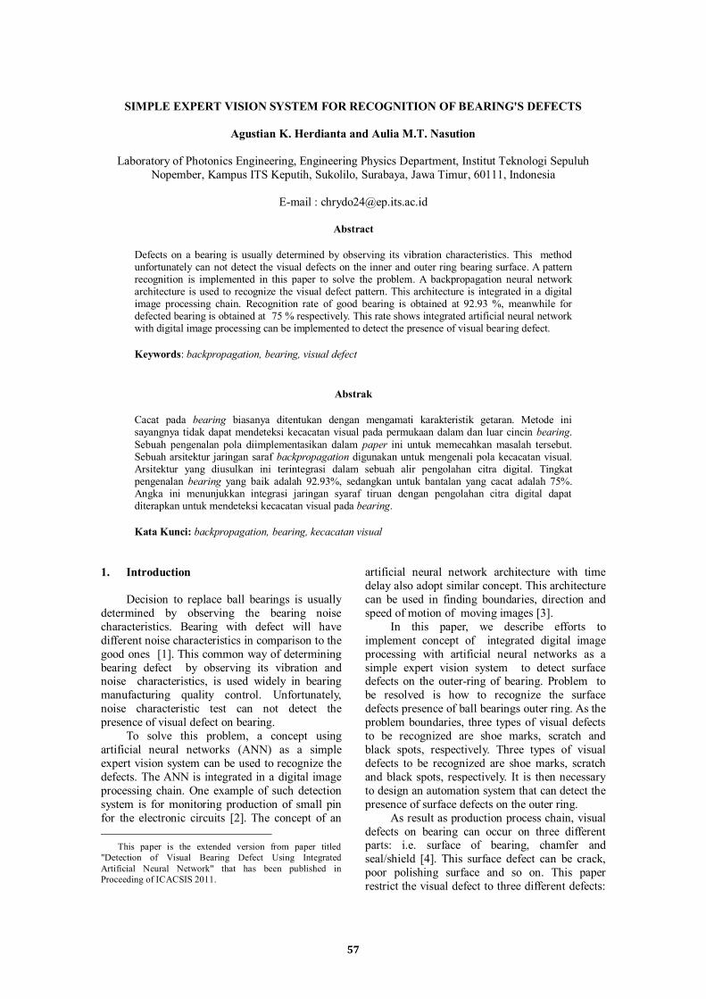
i.e. scratch, shoemark and blackspot. Scratch
appears like white small mark on ball bearing,
meanwhile shoemark appears like black thin line
circles around bearing surface. Both don’t change
the roundness and rounghness of bearing surface.
Blackspot appears like deep grinded mark. Types
of visual defect occur on outer ring can be seen in
figure 1(a), figure 1(b), and figure 1(c).
(a)
(b)
(c)
Figure 1. (a) Shoemark, (b) Scratch, (c) Blackspot.
Visual defects can be seen by naked eyes, so
we can use image processing as foundation of the
solution. Image processing applications are used in various fields, ranging from medicine to
engineering [5]. Various problems related to
image processing can be solved with steps
called image processing chain [6]. Typical chain
of image processing consists step of
preprocessing, data reduction, segmentation,
object detection and image understanding.
Converting from RGB images to grayscale image
is the preprocessing steps. This step is necessary
to be performed in order to simplify the defect
information in acquired images. Usage of Region of Interest (ROI) is used as the step of
segmentation and followed by artificial neural
network (ANN) as the object recognition step.
ROI usage will reduce size of the image and affect
for speed of program execution. Assesment of the
ANN will show the meaning of acquired image
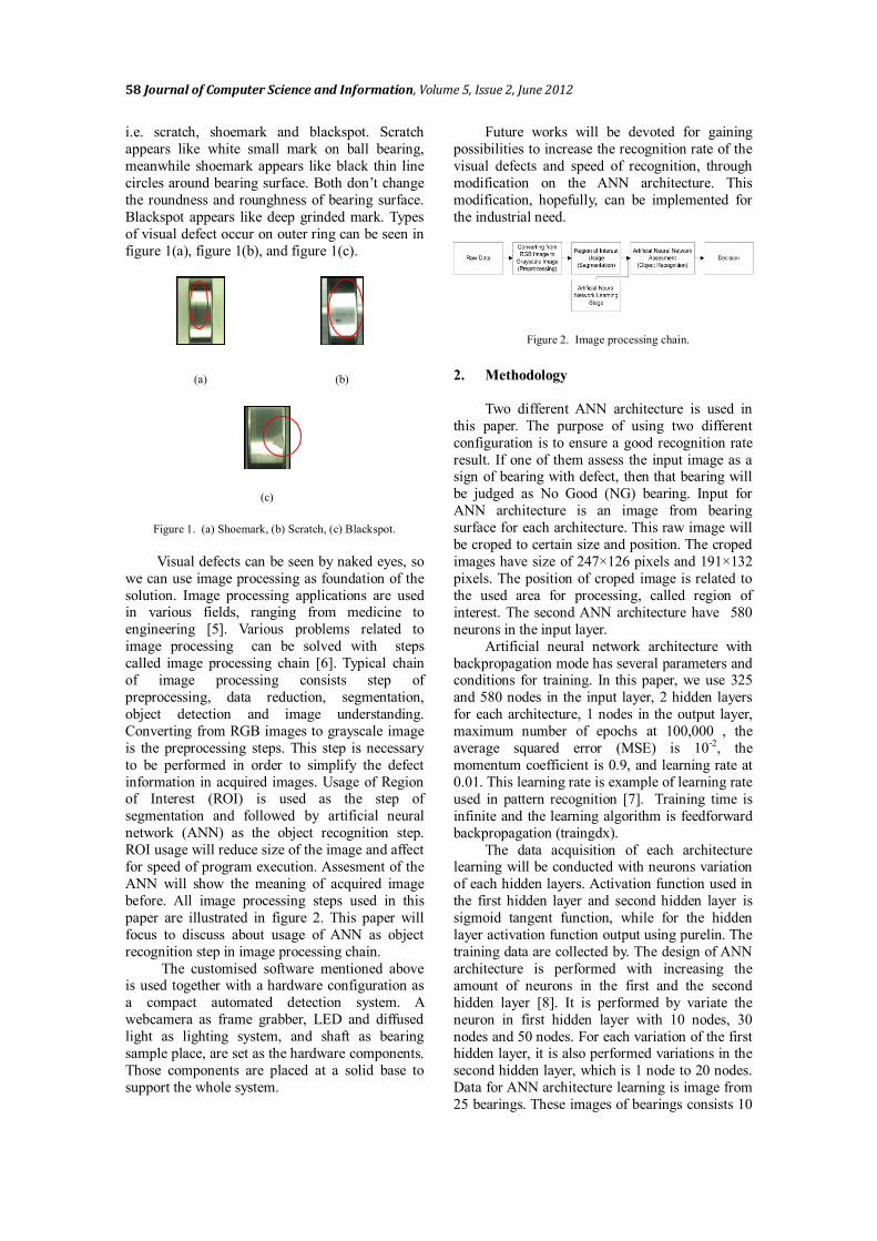
before. All image processing steps used in this
paper are illustrated in figure 2. This paper will
focus to discuss about usage of ANN as object
recognition step in image processing chain.
The customised software mentioned above is used together with a hardware configuration as
a compact automated detection system. A
webcamera as frame grabber, LED and diffused
light as lighting system, and shaft as bearing
sample place, are set as the hardware components.
Those components are placed at a solid base to
support the whole system.
Future works will be devoted for gaining
possibilities to increase the recognition rate of the
visual defects and speed of recognition, through
modification on the ANN architecture. This
modification, hopefully, can be implemented for
the industrial need.
Figure 2. Image processing chain.
2. Methodology
Two different ANN architecture is used in
this paper. The purpose of using two different
configuration is to ensure a good recognition rate
result. If one of them assess the input image as a sign of bearing with defect, then that bearing will
be judged as No Good (NG) bearing. Input for
ANN architecture is an image from bearing
surface for each architecture. This raw image will
be croped to certain size and position. The croped
images have size of 247×126 pixels and 191×132
pixels. The position of croped image is related to
the used area for processing, called region of
interest. The second ANN architecture have 580
neurons in the input layer.
Artificial neural network architecture with
backpropagation mode has several parameters and conditions for training. In this paper, we use 325
and 580 nodes in the input layer, 2 hidden layers
for each architecture, 1 nodes in the output layer,
maximum number of epochs at 100,000 , the
average squared error (MSE) is 10-2, the
momentum coefficient is 0.9, and learning rate at
0.01. This learning rate is example of learning rate
used in pattern recognition [7]. Training time is
infinite and the learning algorithm is feedforward
backpropagation (traingdx).
The data acquisition of each architecture learning will be conducted with neurons variation
of each hidden layers. Activation function used in
the first hidden layer and second hidden layer is
sigmoid tangent function, while for the hidden
layer activation function output using purelin. The
training data are collected by. The design of ANN
architecture is performed with increasing the
amount of neurons in the first and the second
hidden layer [8]. It is performed by variate the
neuron in first hidden layer with 10 nodes, 30
nodes and 50 nodes. For each variation of the first hidden layer, it is also performed variations in the
second hidden layer, which is 1 node to 20 nodes.
Data for ANN architecture learning is image from
25 bearings. These images of bearings consists 10
Herdianta, et al., Simple Expert Vision System for Recognition of Bearing's Defects 59
OK bearings, 4 bearings with scratch defects, 6
bearings with shoemark defects, 4 bearings with
blackspot defects, a bearing with chatter defect.
Target value for OK bearing is 1 and target value
for NG bearing is 0.
Acquisition of data in each learning will be
conducted with variation of the neurons of each
hidden layers. Activation function used in the first
hidden layer and second hidden layer is sigmoid
tangent function, while for the hidden layer
activation function output using purelin. Data is collected by doing a variation on the rate of
learning, the first hidden layer and the second
hidden layer. Variations in the rate of learning is in
the amount of 0.01 and 0.001. These rates of
learning is example of learning rate used in
pattern recognition [7]. The design of ANN
architecture can be performed with the addition of
the layers of hidden layer nodes [8]. At any
learning rate, data acqusition is performed by
variation of the first hidden layer of 10 nodes, 30
nodes and 50 nodes. In each variation of the first hidden layer, data acquisition is performed by
variation of the second hidden layer, which is 1
node to 20 nodes. Data for learning ANN
architecture is the image of the 25 bearings. The
sample bearings consists of 10 OK bearings, 4
bearings with scratch defects, 6 bearings with
shoemark defects, 4 bearings with blackspot
defects, a bearing with chatter defect. Target
value for OK bearing is 1 and target value for NG
bearing is 0.
Shaft
9 c
m
9,5 cm
Web
Camera
48,0°
LED
Web
Camera
Diffuse Light
3 cm
60,4°
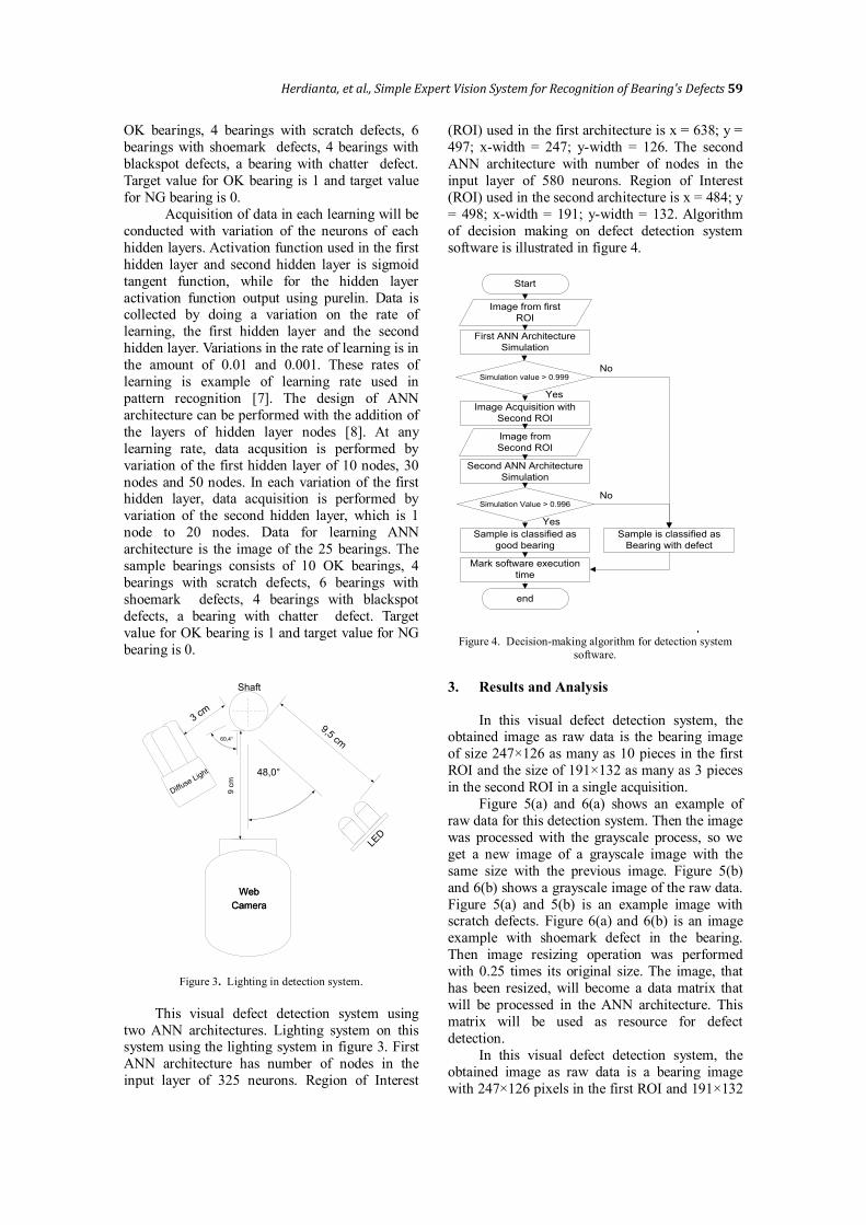
Figure 3. Lighting in detection system.
This visual defect detection system using
two ANN architectures. Lighting system on this system using the lighting system in figure 3. First
ANN architecture has number of nodes in the
input layer of 325 neurons. Region of Interest
(ROI) used in the first architecture is x = 638; y =
497; x-width = 247; y-width = 126. The second
ANN architecture with number of nodes in the
input layer of 580 neurons. Region of Interest
(ROI) used in the second architecture is x = 484; y
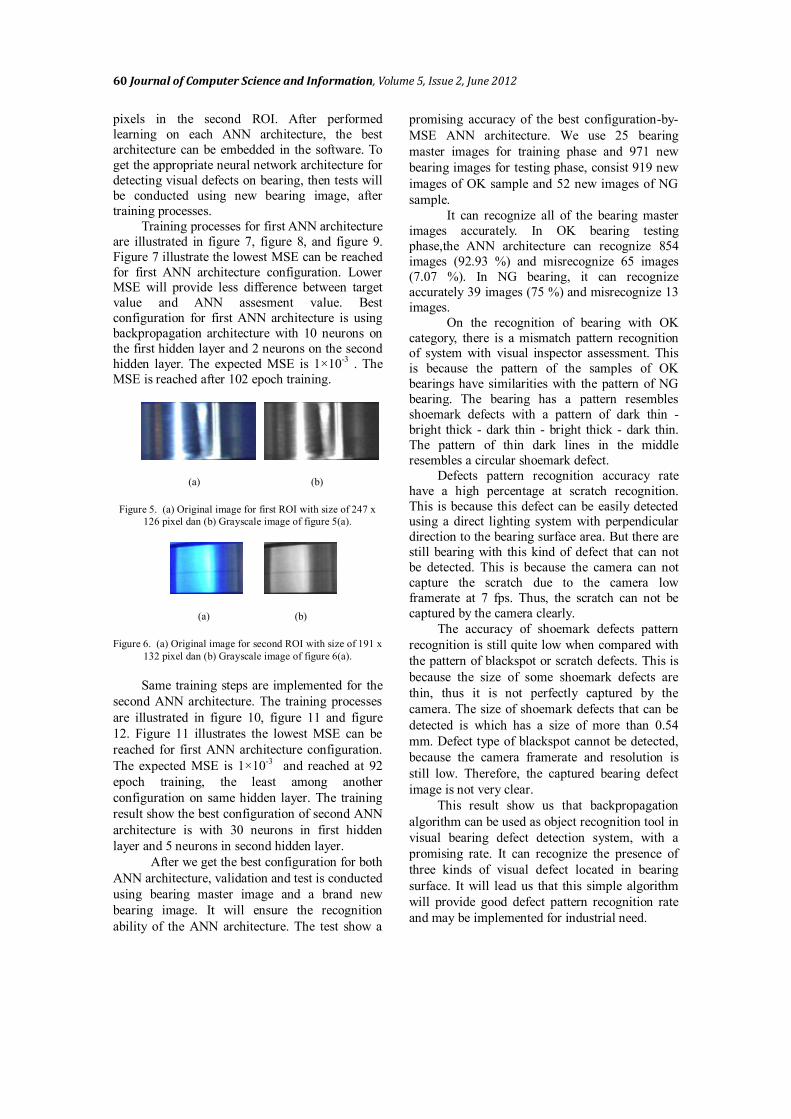
= 498; x-width = 191; y-width = 132. Algorithm
of decision making on defect detection system
software is illustrated in figure 4.
Start
Image from first
ROI
First ANN Architecture
Simulation
Simulation value > 0.999
Image Acquisition with
Second ROI
Second ANN Architecture
Simulation
Image from
Second ROI
Simulation Value > 0.996
Sample is classified as
good bearing
Mark software execution
time
end
Sample is classified as
Bearing with defect
Yes
Yes
No
No
Figure 4. Decision-making algorithm for detection system
software.
3. Results and Analysis
In this visual defect detection system, the obtained image as raw data is the bearing image
of size 247×126 as many as 10 pieces in the first
ROI and the size of 191×132 as many as 3 pieces
in the second ROI in a single acquisition.
Figure 5(a) and 6(a) shows an example of
raw data for this detection system. Then the image
was processed with the grayscale process, so we
get a new image of a grayscale image with the
same size with the previous image. Figure 5(b)
and 6(b) shows a grayscale image of the raw data.
Figure 5(a) and 5(b) is an example image with scratch defects. Figure 6(a) and 6(b) is an image
example with shoemark defect in the bearing.
Then image resizing operation was performed
with 0.25 times its original size. The image, that
has been resized, will become a data matrix that
will be processed in the ANN architecture. This
matrix will be used as resource for defect
detection.
In this visual defect detection system, the
obtained image as raw data is a bearing image
with 247×126 pixels in the first ROI and 191×132
60 Journal of Computer Science and Information, Volume 5, Issue 2, June 2012
pixels in the second ROI. After performed
learning on each ANN architecture, the best
architecture can be embedded in the software. To
get the appropriate neural network architecture for
detecting visual defects on bearing, then tests will
be conducted using new bearing image, after
training processes.
Training processes for first ANN architecture
are illustrated in figure 7, figure 8, and figure 9.
Figure 7 illustrate the lowest MSE can be reached
for first ANN architecture configuration. Lower MSE will provide less difference between target
value and ANN assesment value. Best
configuration for first ANN architecture is using
backpropagation architecture with 10 neurons on
the first hidden layer and 2 neurons on the second
hidden layer. The expected MSE is 1×10⁻³ . The
MSE is reached after 102 epoch training.
(a) (b)
Figure 5. (a) Original image for first ROI with size of 247 x
126 pixel dan (b) Grayscale image of figure 5(a).
(a) (b)
Figure 6. (a) Original image for second ROI with size of 191 x
132 pixel dan (b) Grayscale image of figure 6(a).
Same training steps are implemented for the
second ANN architecture. The training processes
are illustrated in figure 10, figure 11 and figure
12. Figure 11 illustrates the lowest MSE can be
reached for first ANN architecture configuration.
The expected MSE is 1×10⁻³ and reached at 92
epoch training, the least among another
configuration on same hidden layer. The training
result show the best configuration of second ANN
architecture is with 30 neurons in first hidden
layer and 5 neurons in second hidden layer.
After we get the best configuration for both
ANN architecture, validation and test is conducted
using bearing master image and a brand new
bearing image. It will ensure the recognition
ability of the ANN architecture. The test show a
promising accuracy of the best configuration-by-
MSE ANN architecture. We use 25 bearing
master images for training phase and 971 new
bearing images for testing phase, consist 919 new
images of OK sample and 52 new images of NG
sample.
It can recognize all of the bearing master
images accurately. In OK bearing testing
phase,the ANN architecture can recognize 854
images (92.93 %) and misrecognize 65 images
(7.07 %). In NG bearing, it can recognize
accurately 39 images (75 %) and misrecognize 13
images.
On the recognition of bearing with OK
category, there is a mismatch pattern recognition of system with visual inspector assessment. This
is because the pattern of the samples of OK
bearings have similarities with the pattern of NG
bearing. The bearing has a pattern resembles
shoemark defects with a pattern of dark thin -
bright thick - dark thin - bright thick - dark thin.
The pattern of thin dark lines in the middle
resembles a circular shoemark defect.
Defects pattern recognition accuracy rate
have a high percentage at scratch recognition.
This is because this defect can be easily detected using a direct lighting system with perpendicular
direction to the bearing surface area. But there are
still bearing with this kind of defect that can not
be detected. This is because the camera can not
capture the scratch due to the camera low
framerate at 7 fps. Thus, the scratch can not be
captured by the camera clearly.
The accuracy of shoemark defects pattern
recognition is still quite low when compared with
the pattern of blackspot or scratch defects. This is
because the size of some shoemark defects are
thin, thus it is not perfectly captured by the
camera. The size of shoemark defects that can be
detected is which has a size of more than 0.54
mm. Defect type of blackspot cannot be detected,
because the camera framerate and resolution is
still low. Therefore, the captured bearing defect
image is not very clear.
This result show us that backpropagation
algorithm can be used as object recognition tool in
visual bearing defect detection system, with a
promising rate. It can recognize the presence of
three kinds of visual defect located in bearing
surface. It will lead us that this simple algorithm
will provide good defect pattern recognition rate
and may be implemented for industrial need.

Herdianta, et al., Simple Expert Vision System for Recognition of Bearing's Defects 61
Figure 7. Training parameter for first ANN architecture with
10 neurons in first hidden layer and 2 neurons in second
hidden layer.
Figure 8. Training parameter for first ANN architecture with
30 neurons in first hidden layer and 2 neurons in second
hidden layer.
Figure 9. Training parameter for first ANN architecture with
50 neurons in first hidden layer and 2 neurons in second
hidden layer.
Figure 10. Training parameter for second ANN architecture
with 10 neurons in first hidden layer and 5 neurons in second
hidden layer.
Figure 11. Training parameter for second ANN architecture
with 30 neurons in first hidden layer and 5 neurons in second
hidden layer.
Figure 12. Training parameter for second ANN architecture
with 50 neurons in first hidden layer and 5 neurons in second
hidden layer.
62 Journal of Computer Science and Information, Volume 5, Issue 2, June 2012
4. Conclusion
The conclusion can be drawn about the
determination of the presence of surface defects
on ball bearings using digital image processing is
as follows. Pattern recognition of visual defects
on the bearing surface can be performed using
integrated artificial neural network with digital
image processing as foundation of a simple expert
vision system to detect the presence of visual
bearing defect. All of artificial neural network architectures used in this paper are
backpropagation.
Future works can be devoted with designing
prototypes by using development of object
recognition tool. It can be done by using other
artificial intelegence algorithm, like ANFIS,
Neuro-Fuzzy, Genetic-Algorithm, etc.
References
[1] S.M. Taribuka, “Pengambilan Keputusan Penggantian Ball Bearing pada Motor Bakar
Torak Berbasis Monitoring Kondisi,” Ph.D
Thesis, Department of Marine Technology,
Faculty of Marine Technology, Institut
Teknologi Sepuluh Nopember, Indonesia,
2010.
[2] Y. Furukawa & H. Sakuma, “Automatic
Detection of Defects among Small Pins
Group - Inspection of Connector-Plug Pins
by the Use of lmage Processing Associated
with Neural Network,” CIRP Annals –
Manufacturing Technology, vol. 41, pp. 589-
592, 1992.
[3] C. Wohler & J.K. Anlauf, “A time delay
neural network algorithm for estimating
image-pattern shape and motion,” Image and
Vision Computing, vol. 17, pp. 281–294,
1999.
[4] NSK, New Bearing Doctor, NSK Ltd, Japan, 2008.
[5] Acharya & Ray, Image Processing:
Principles and Applications, John Wiley &
Sons, New Jersey, 2005.
[6] M. Egmont-Petersen, D.D. Ridder, & H.
Handels, “Image Processing with Neural
Network – A Review,” Pattern Recognition,
vol. 35, pp. 2279–2301, 2002.
[7] A. Wiyanti, “Klasifikasi komposisi sel darah
putih dengan menggunakan multilayer
perceptron network,” B.S Thesis, Department of Physics Engineering, Faculty
of Industrial Technology, Institut Teknologi
Sepuluh Nopember, 2010.
[8] Y. Liu & X. Yao, “Evolutianary design of
artificial neural networks with different
nodes” In Proceedings of IEEE International
Conference on Evolutianary Computation,
pp. 670-675, 1996.