Embed Size (px)
Citation preview
Unrestricted / © Siemens AG 2016. All Rights Reserved. siemens.com/answers
SIMOTION Winder V3.1.0
Unrestricted / © Siemens AG 2016. All Rights Reserved.
► Project
Generator
► SIZER
► Example
Configuration
► Function Block
Overview
► Scope of
Functionality
► Contents of the
Application
► Benefits when
using the
Application
► Introduction
Converting Toolbox
Introduction
The application SIMOTION Winder was developed with the objective to address many of the known winder applications using one application software.
If required, the application can be configured and/or also changed.
Using the SIMOTION control platform the application “SIMOTION Winder” allows winders and un-winders to be implemented in a wide range of applications, e.g. foil making machines, printing machines, coating machines...
Can be combined with other applications like:
SIMOTION Axis Function Block
SIMOTION Splice Control
SIMOTION Traversing Drive
SINAMICS DCC Load Sharing
Unrestricted / © Siemens AG 2016. All Rights Reserved.
► Project
Generator
► SIZER
► Example
Configuration
► Function Block
Overview
► Scope of
Functionality
► Contents of the
Application
► Benefits when
using the
Application
► Introduction
Converting Toolbox
Benefits when using the Application
• Shorter engineering and service time (same look & feel)
• Can be used in all programming languages
• Industry standards are used (PLC open)
• Supported by Application Centers World Wide
• Regularly updated on Intranet
• Open source code so that you can adapt the functions to your
requirements
• User Manuals in English and German
• Easy learning using pre-programmed application examples
• Free of Charge

Unrestricted / © Siemens AG 2016. All Rights Reserved.
► Project
Generator
► SIZER
► Example
Configuration
► Function Block
Overview
► Scope of
Functionality
► Contents of the
Application
► Benefits when
using the
Application
► Introduction
Converting Toolbox
Contents of the Application
• PowerPoint presentation (English / German)
• Units / libraries (programming in ST or MCC)
• User Manuals (English and German)
• Example machine project for SIMOTION
Unrestricted / © Siemens AG 2016. All Rights Reserved.
► Project
Generator
► SIZER
► Example
Configuration
► Function Block
Overview
► Scope of
Functionality
► Contents of the
Application
► Benefits when
using the
Application
► Introduction
Converting Toolbox
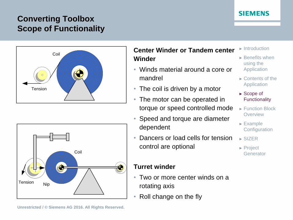
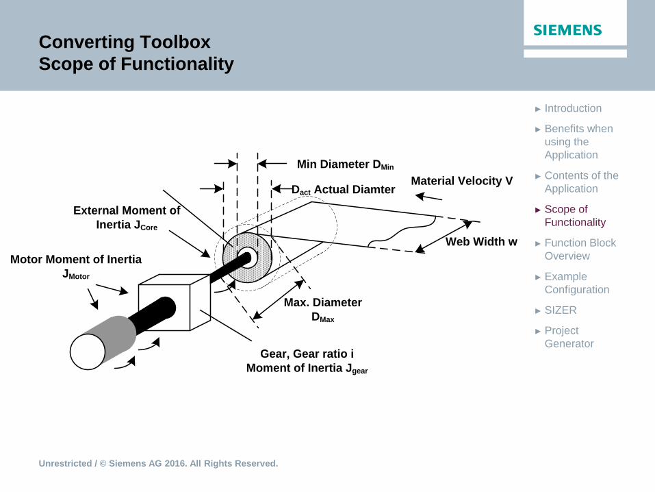
Scope of Functionality
Center Winder or Tandem center
Winder
• Winds material around a core or
mandrel
• The coil is driven by a motor
• The motor can be operated in
torque or speed controlled mode
• Speed and torque are diameter
dependent
• Dancers or load cells for tension
control are optional
Turret winder
• Two or more center winds on a
rotating axis
• Roll change on the fly
Tension
Coil
Nip
Tension
Coil
Unrestricted / © Siemens AG 2016. All Rights Reserved.
► Project
Generator
► SIZER
► Example
Configuration
► Function Block
Overview
► Scope of
Functionality
► Contents of the
Application
► Benefits when
using the
Application
► Introduction
Converting Toolbox
Scope of Functionality
Min Diameter DMin
Max. Diameter
DMax
Web Width w
Gear, Gear ratio i
Moment of Inertia Jgear
Material Velocity V
External Moment of
Inertia JCore
Motor Moment of Inertia
JMotor
Dact Actual Diamter

Unrestricted / © Siemens AG 2016. All Rights Reserved.
► Project
Generator
► SIZER
► Example
Configuration
► Function Block
Overview
► Scope of
Functionality
► Contents of the
Application
► Benefits when
using the
Application
► Introduction
V+ , F+
Winder from above
V+, F+
Winder from below
V+, F+
Unwinder from below
V+, F+
Unwinder from above
n+
no+
Mf+
MP+
MT+
n-
no-
Mf-
MP-
MT-
n-
no+
Mf-
MP-
MT+
n+
no-
Mf+
MP+
MT-
Mf: Friction Torque
MP: Torque Precontrol
MT: Tension
n: winder speed
no: speed override
Converting Toolbox
Scope of Functionality

Unrestricted / © Siemens AG 2016. All Rights Reserved.
► Project
Generator
► SIZER
► Example
Configuration
► Function Block
Overview
► Scope of
Functionality
► Contents of the
Application
► Benefits when
using the
Application
► Introduction
Converting Toolbox
Scope of Functionality – Process interfacing
The interfacing to the process is based on the sWinderConfig parameter
toLineAxis. The following alternatives are implemented:
toLineAxis = TO#NIL:
There is no master axis specified. The coupling is based on the input
variable lineAxisMotionVector.
toLineAxis = TO#driveAxis:
The master axis is a speed controlled axis. The reference diameter of
the axis has to be specified. Optional position information has to be
entered externally via I/O-structure.
toLineAxis = TO#posAxis:
The master axis is a positioning axis. Position information is available.
toLineAxis = TO#externalEncoderType:
The master axis is a machine encoder. Position information is available.
Unrestricted / © Siemens AG 2016. All Rights Reserved.
► Project
Generator
► SIZER
► Example
Configuration
► Function Block
Overview
► Scope of
Functionality
► Contents of the
Application
► Benefits when
using the
Application
► Introduction
Converting Toolbox
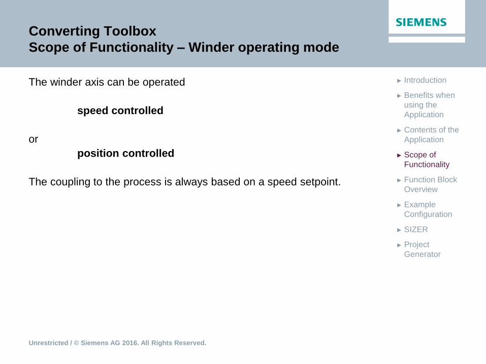
Scope of Functionality – Winder operating mode
The winder axis can be operated
speed controlled
or
position controlled
The coupling to the process is always based on a speed setpoint.

Unrestricted / © Siemens AG 2016. All Rights Reserved.
► Project
Generator
► SIZER
► Example
Configuration
► Function Block
Overview
► Scope of
Functionality
► Contents of the
Application
► Benefits when
using the
Application
► Introduction
Converting Toolbox
Scope of Functionality – System of units
Configuration data Values
sWinderConfig.sUnitConfig.eUnitLineAxis
Velocity
M_MIN, MM_MIN, M_S, MM_S, FT_MIN, INCH_MIN,
FT_S, INCH_S, DEG_S_PRINT
sWinderConfig.sUnitConfig.eUnitLineAxis
Acceleration
M_S2, MM_S2, FT_S2, INCH_S2, DEG_S2_PRINT
Configuration data Values
sLTCConfig.eUnitLTCAxisVelocity RPM, RPS, DEG_MIN, DEG_S
Measured variable Unit Metric Anglo-American
Length LU e.g.: m (meter) e.g.: ft (feet)
Length (base unit) Lub m (meter) ft (feet)
Velocity LU / TU e.g.: m / min e.g.: ft / min
Acceleration LU / s² e.g.: m / s² e.g.: ft / s²
Speed rpTU or ° / TU e.g.: rpm e.g.: rpm
Mass, Weight m kg lb
Density m / LUb³ kg / m³ lb / ft³
Inertia J = mLUb² kgm² lbft²
Torque M = mLUb²/s² Nm= kgm² / s² lbf ft = lbft² / s²
Force, Tension Z = mLUb/s² N = kg m /s² lbf = lb ft / s²
Unrestricted / © Siemens AG 2016. All Rights Reserved.
► Project
Generator
► SIZER
► Example
Configuration
► Function Block
Overview
► Scope of
Functionality
► Contents of the
Application
► Benefits when
using the
Application
► Introduction
Converting Toolbox
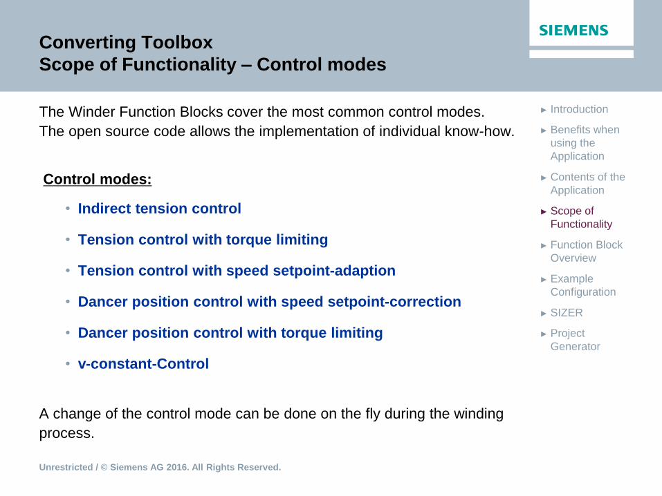
Scope of Functionality – Control modes
The Winder Function Blocks cover the most common control modes.
The open source code allows the implementation of individual know-how.
Control modes:
• Indirect tension control
• Tension control with torque limiting
• Tension control with speed setpoint-adaption
• Dancer position control with speed setpoint-correction
• Dancer position control with torque limiting
• v-constant-Control
A change of the control mode can be done on the fly during the winding
process.
Unrestricted / © Siemens AG 2016. All Rights Reserved.
► Project
Generator
► SIZER
► Example
Configuration
► Function Block
Overview
► Scope of
Functionality
► Contents of the
Application
► Benefits when
using the
Application
► Introduction
Converting Toolbox
Scope of Functionality
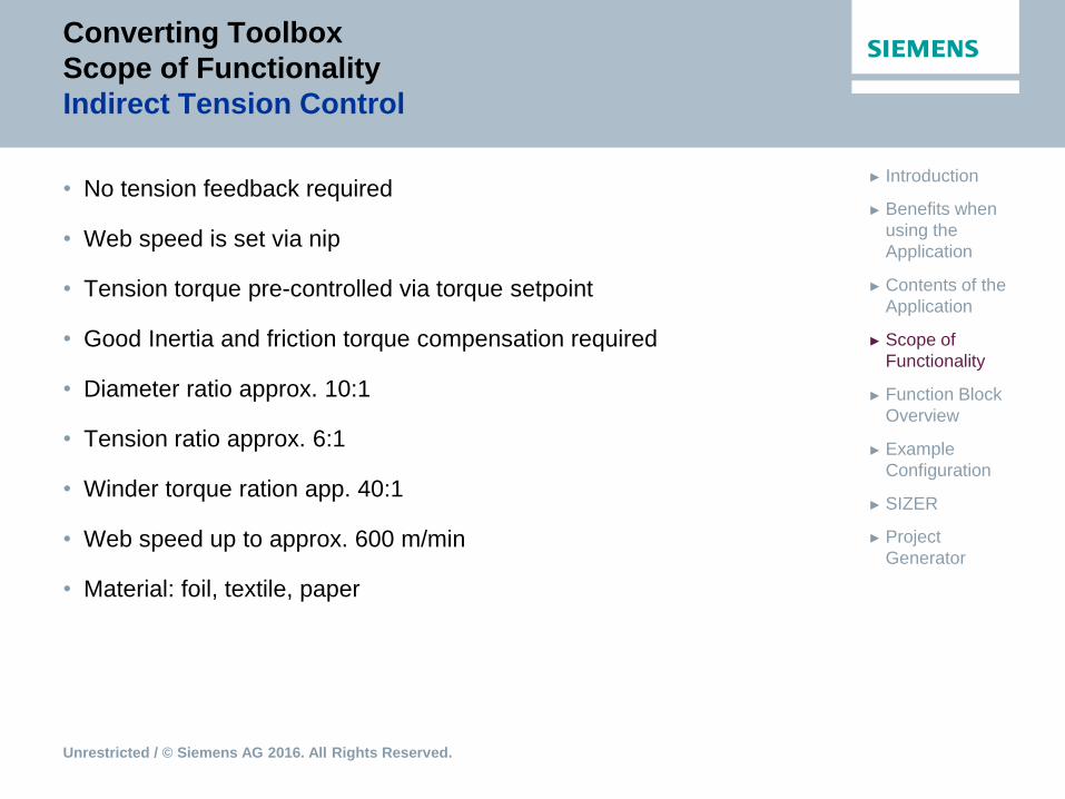
Indirect Tension Control
• No tension feedback required
• Web speed is set via nip
• Tension torque pre-controlled via torque setpoint
• Good Inertia and friction torque compensation required
• Diameter ratio approx. 10:1
• Tension ratio approx. 6:1
• Winder torque ration app. 40:1
• Web speed up to approx. 600 m/min
• Material: foil, textile, paper
Unrestricted / © Siemens AG 2016. All Rights Reserved.
► Project
Generator
► SIZER
► Example
Configuration
► Function Block
Overview
► Scope of
Functionality
► Contents of the
Application
► Benefits when
using the
Application
► Introduction
Converting Toolbox
Scope of Functionality
Indirect Tension Control
Unrestricted / © Siemens AG 2016. All Rights Reserved.
► Project
Generator
► SIZER
► Example
Configuration
► Function Block
Overview
► Scope of
Functionality
► Contents of the
Application
► Benefits when
using the
Application
► Introduction
Converting Toolbox
Scope of Functionality
Tension control with torque limiting
• Tension measuring device required
• Web speed is set via nip
• Tension Torque pre-controlled via torque set point
• Good Inertia and friction torque compensation required
• Diameter ratio app. 15:1
• Tension ratio app. 20:1
• Winder torque app. 100:1
• Web velocity up to app. 2000 m/min
• Tension control via torque limitation
• Material: paper, thin film
Unrestricted / © Siemens AG 2016. All Rights Reserved.
► Project
Generator
► SIZER
► Example
Configuration
► Function Block
Overview
► Scope of
Functionality
► Contents of the
Application
► Benefits when
using the
Application
► Introduction
Converting Toolbox
Scope of Functionality
Tension control with torque limiting

Unrestricted / © Siemens AG 2016. All Rights Reserved.
► Project
Generator
► SIZER
► Example
Configuration
► Function Block
Overview
► Scope of
Functionality
► Contents of the
Application
► Benefits when
using the
Application
► Introduction
Converting Toolbox
Scope of Functionality
Tension control with speed setpoint-adaption
• Tension measuring device required
• Web speed is set via nip
• Tension torque controlled via additional velocity setpoint
• Diameter ratio app. 15:1
• Tension ratio app. 20:1
• Winder torque app. 100:1
• Web velocity over 2000 m/min
• Material: Elastic, expandable material

Unrestricted / © Siemens AG 2016. All Rights Reserved.
► Project
Generator
► SIZER
► Example
Configuration
► Function Block
Overview
► Scope of
Functionality
► Contents of the
Application
► Benefits when
using the
Application
► Introduction
Converting Toolbox
Scope of Functionality
Tension control with speed setpoint-adaption
Winding axis
Torque
precontrol
Acce
lera
tio
n s
etp
oin
t
Setpoint velocity
Ve
locity s
etp
oin
t
Precontrol
torque
Diameter
calculation
Ve
locity/p
ositio
n
se
tpo
int
Speed/position
Speed setpoint
Winding axisdiameter
Speed
setpoint
FTension [N]
Master axis
+Speed
controller
Current
controller
Auxiliary
torqueTorque limit
Po
we
r u
nit
Actu
al sp
ee
d
va
lue
Winding drive
Tension
controller
Co
rre
ectio
n v
alu
e
Tension
setpoint
Tension actual value
+
Setpoint
preparation
(Rampgenerator)
<FBWinder>.additive
Torque
<FBWinder>
.velocity<FBDiameter
Calculation>.
diamActVal
<FBWinder>.
tensionSetpoint
<FBWinder>.actValuePID

Unrestricted / © Siemens AG 2016. All Rights Reserved.
► Project
Generator
► SIZER
► Example
Configuration
► Function Block
Overview
► Scope of
Functionality
► Contents of the
Application
► Benefits when
using the
Application
► Introduction
Converting Toolbox
Scope of Functionality
Dancer position control with speed setpoint-correction
• Dancer position measuring device required (e.g. potentiometer, encoder)
• Web speed is set via nip
• Web tension is controlled via additional speed setpoint
• Dancer influences the web path
• Diameter ratio up to app. 15:1
• Tension ration controlled via dancer
• Winder torque ratio up to app. 40:1, depending on the dancer system
• Web speed up to app. 2000 m/min
• Material: rubber, cable, textile, film and paper
Unrestricted / © Siemens AG 2016. All Rights Reserved.
► Project
Generator
► SIZER
► Example
Configuration
► Function Block
Overview
► Scope of
Functionality
► Contents of the
Application
► Benefits when
using the
Application
► Introduction
Converting Toolbox
Scope of Functionality
Dancer position control with speed setpoint-correction

Unrestricted / © Siemens AG 2016. All Rights Reserved.
► Project
Generator
► SIZER
► Example
Configuration
► Function Block
Overview
► Scope of
Functionality
► Contents of the
Application
► Benefits when
using the
Application
► Introduction
Converting Toolbox
Scope of Functionality
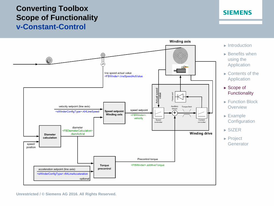
v-Constant-Control
• Winder is controlled to run with constant web speed (web speed
command value)
• No tension control
• Web material tachometer required (for internal diameter calculation)
• No nip role necessary
• Diameter ratio up to app. 15:1
• Web speed: depending from mechanical construction
• Preferably for sorters
Unrestricted / © Siemens AG 2016. All Rights Reserved.
► Project
Generator
► SIZER
► Example
Configuration
► Function Block
Overview
► Scope of
Functionality
► Contents of the
Application
► Benefits when
using the
Application
► Introduction
Converting Toolbox
Scope of Functionality
v-Constant-Control
Unrestricted / © Siemens AG 2016. All Rights Reserved.
► Project
Generator
► SIZER
► Example
Configuration
► Function Block
Overview
► Scope of
Functionality
► Contents of the
Application
► Benefits when
using the
Application
► Introduction
Converting Toolbox
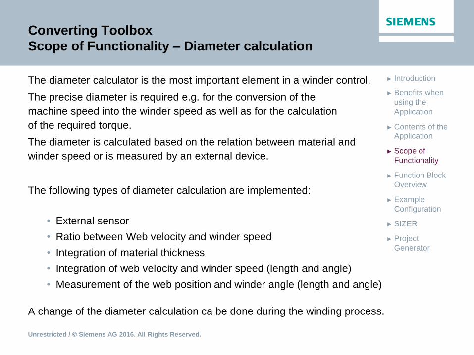
Scope of Functionality – Diameter calculation
The diameter calculator is the most important element in a winder control.
The precise diameter is required e.g. for the conversion of the
machine speed into the winder speed as well as for the calculation
of the required torque.
The diameter is calculated based on the relation between material and
winder speed or is measured by an external device.
The following types of diameter calculation are implemented:
• External sensor
• Ratio between Web velocity and winder speed
• Integration of material thickness
• Integration of web velocity and winder speed (length and angle)
• Measurement of the web position and winder angle (length and angle)
A change of the diameter calculation ca be done during the winding process.
Unrestricted / © Siemens AG 2016. All Rights Reserved.
► Project
Generator
► SIZER
► Example
Configuration
► Function Block
Overview
► Scope of
Functionality
► Contents of the
Application
► Benefits when
using the
Application
► Introduction
Converting Toolbox
Scope of Functionality – Diameter calculation
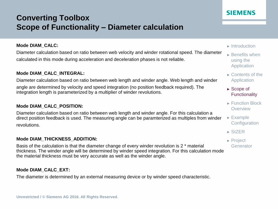
Mode DIAM_CALC:
Diameter calculation based on ratio between web velocity and winder rotational speed. The diameter
calculated in this mode during acceleration and deceleration phases is not reliable.
Mode DIAM_CALC_INTEGRAL:
Diameter calculation based on ratio between web length and winder angle. Web length and winder
angle are determined by velocity and speed integration (no position feedback required). The integration length is parameterized by a multiplier of winder revolutions.
Mode DIAM_CALC_POSITION:
Diameter calculation based on ratio between web length and winder angle. For this calculation a direct position feedback is used. The measuring angle can be paramterized as multiples from winder
revolutions.
Mode DIAM_THICKNESS_ADDITION:
Basis of the calculation is that the diameter change of every winder revolution is 2 * material thickness. The winder angle will be determined by winder speed integration. For this calculation mode the material thickness must be very accurate as well as the winder angle.
Mode DIAM_CALC_EXT:
The diameter is determined by an external measuring device or by winder speed characteristic.
Unrestricted / © Siemens AG 2016. All Rights Reserved.
► Project
Generator
► SIZER
► Example
Configuration
► Function Block
Overview
► Scope of
Functionality
► Contents of the
Application
► Benefits when
using the
Application
► Introduction
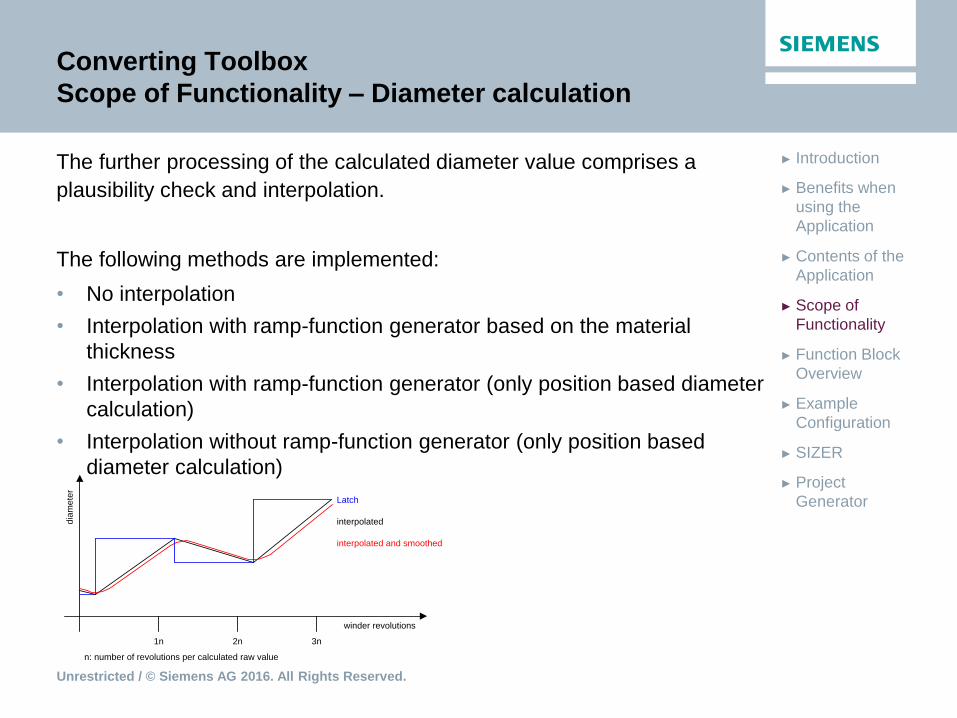
winder revolutions
dia
me
ter
2n1n 3n
Latch
interpolated
interpolated and smoothed
n: number of revolutions per calculated raw value
Converting Toolbox
Scope of Functionality – Diameter calculation
The further processing of the calculated diameter value comprises a
plausibility check and interpolation.
The following methods are implemented:
• No interpolation
• Interpolation with ramp-function generator based on the material
thickness
• Interpolation with ramp-function generator (only position based diameter
calculation)
• Interpolation without ramp-function generator (only position based
diameter calculation)

Unrestricted / © Siemens AG 2016. All Rights Reserved.
► Project
Generator
► SIZER
► Example
Configuration
► Function Block
Overview
► Scope of
Functionality
► Contents of the
Application
► Benefits when
using the
Application
► Introduction
Converting Toolbox
Scope of Functionality – Diameter calculation
Unrestricted / © Siemens AG 2016. All Rights Reserved.
► Project
Generator
► SIZER
► Example
Configuration
► Function Block
Overview
► Scope of
Functionality
► Contents of the
Application
► Benefits when
using the
Application
► Introduction
Converting Toolbox
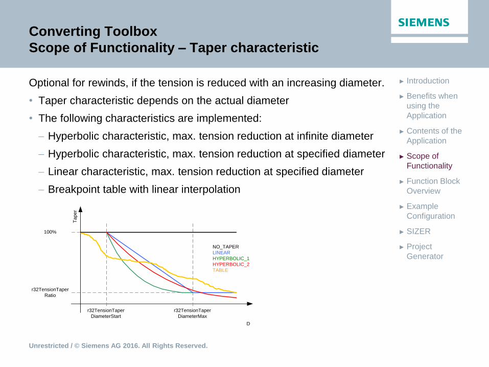
Scope of Functionality – Taper characteristic
Optional for rewinds, if the tension is reduced with an increasing diameter.
• Taper characteristic depends on the actual diameter
• The following characteristics are implemented:
Hyperbolic characteristic, max. tension reduction at infinite diameter
Hyperbolic characteristic, max. tension reduction at specified diameter
Linear characteristic, max. tension reduction at specified diameter
Breakpoint table with linear interpolation
D
Ta
pe
r
r32TensionTaper
Ratio
100%
r32TensionTaper
DiameterStart
r32TensionTaper
DiameterMax
NO_TAPER
LINEAR
HYPERBOLIC_1
HYPERBOLIC_2
TABLE

Unrestricted / © Siemens AG 2016. All Rights Reserved.
► Project
Generator
► SIZER
► Example
Configuration
► Function Block
Overview
► Scope of
Functionality
► Contents of the
Application
► Benefits when
using the
Application
► Introduction
Converting Toolbox
Scope of Functionality – Controller adaption
• Controller gain of the tension/position controller is adaptable based on the
actual diameter
higher gain at higher diameter
• Controller gain of the speed controller is adaptable based on the moment
of inertia or the diameter of the roll
higher controller performance with high load conditions

Unrestricted / © Siemens AG 2016. All Rights Reserved.
► Project
Generator
► SIZER
► Example
Configuration
► Function Block
Overview
► Scope of
Functionality
► Contents of the
Application
► Benefits when
using the
Application
► Introduction
Converting Toolbox
Scope of Functionality – Torque pre-control
The torque for the winding process is calculated from three components:
1. Acceleration / Deceleration torque
During acceleration or deceleration of the material an additional torque
component is switched on the drive for more dynamic reaction and to
prevent tension fluctuations.
The acceleration compensation is based on the diameter, the web
width, the gear ratio and the material density.
2. Friction compensation
Compensation of mechanical losses for precise adjustments
of the tension
3. Tension pre-control
Adjustment of the tension, especially in the control mode indirect
tension control
Using the torque pre-control, the technology data block is mandatory.
Unrestricted / © Siemens AG 2016. All Rights Reserved.
► Project
Generator
► SIZER
► Example
Configuration
► Function Block
Overview
► Scope of
Functionality
► Contents of the
Application
► Benefits when
using the
Application
► Introduction
Converting Toolbox
Scope of Functionality – Tension mode (web mode)
• Tension operation can only be enabled if the control is in operation and
web break detection is not signaling an error
• It is recommended to only enable tension operation in machine stand still
• Tension or position setpoint will be enabled using adaptable ramp
functions
• If tension operation is not active, the diameter computer and the speed
override are disabled
Unrestricted / © Siemens AG 2016. All Rights Reserved.
► Project
Generator
► SIZER
► Example
Configuration
► Function Block
Overview
► Scope of
Functionality
► Contents of the
Application
► Benefits when
using the
Application
► Introduction
Converting Toolbox
Scope of Functionality –Technology controller
The technology controller based on the functionality of a PID-controller for
the usage in e.g. a dancer-postion- or tension-controller.
• Setpoint ramp function generator with settable input
• PID-controller
• RFG as controller output for smooth transitions
• Kp-Adaption
• Optional D-portion in the actual value channel

Unrestricted / © Siemens AG 2016. All Rights Reserved.
► Project
Generator
► SIZER
► Example
Configuration
► Function Block
Overview
► Scope of
Functionality
► Contents of the
Application
► Benefits when
using the
Application
► Introduction
Converting Toolbox
Scope of Functionality – Residual length calculation
Residual length calculation – FCRLC (LConLib)
• The residual length of a roll can be calculated by entering the following
parameters:
Web thickness
Actual diameter
Target diameter
• Output either the length of the material on the roll or the length of the
material still to be wound
d2d1
Materialmenge zwischen
aktuellen und Zieldurchmesser
d1
d2
X
X
Δlength
p
p
Unrestricted / © Siemens AG 2016. All Rights Reserved.
► Project
Generator
► SIZER
► Example
Configuration
► Function Block
Overview
► Scope of
Functionality
► Contents of the
Application
► Benefits when
using the
Application
► Introduction
Converting Toolbox
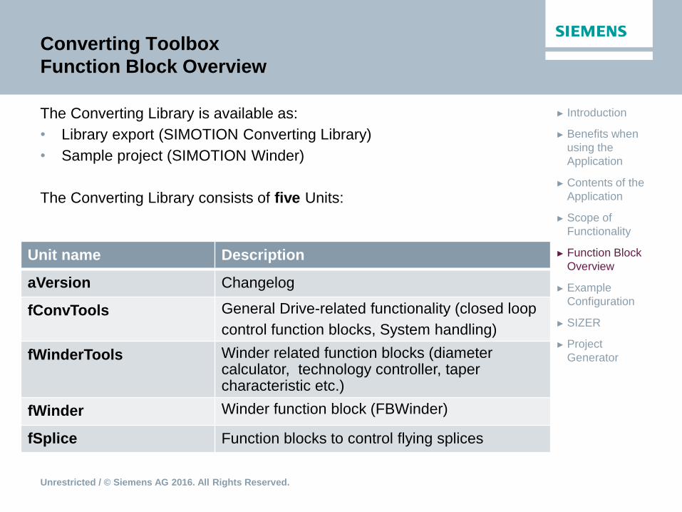
Function Block Overview
The Converting Library is available as:
• Library export (SIMOTION Converting Library)
• Sample project (SIMOTION Winder)
The Converting Library consists of five Units:
Unit name Description
aVersion Changelog
fConvTools General Drive-related functionality (closed loop
control function blocks, System handling)
fWinderTools Winder related function blocks (diameter calculator, technology controller, taper characteristic etc.)
fWinder Winder function block (FBWinder)
fSplice Function blocks to control flying splices

Unrestricted / © Siemens AG 2016. All Rights Reserved.
► Project
Generator
► SIZER
► Example
Configuration
► Function Block
Overview
► Scope of
Functionality
► Contents of the
Application
► Benefits when
using the
Application
► Introduction
Converting Toolbox
Function Block Overview – FBWinder
Unrestricted / © Siemens AG 2016. All Rights Reserved.
► Project
Generator
► SIZER
► Example
Configuration
► Function Block
Overview
► Scope of
Functionality
► Contents of the
Application
► Benefits when
using the
Application
► Introduction
Converting Toolbox
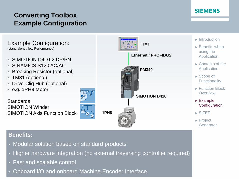
Example Configuration
Example Configuration: (stand alone / low Performance)
• SIMOTION D410-2 DP/PN
• SINAMICS S120 AC/AC
• Breaking Resistor (optional)
• TM31 (optional)
• Drive-Cliq Hub (optional)
• e.g. 1PH8 Motor
Standards:
SIMOTION Winder
SIMOTION Axis Function Block
Benefits:
Modular solution based on standard products
Higher hardware integration (no external traversing controller required)
Fast and scalable control
Onboard I/O and onboard Machine Encoder Interface
Ethernet / PROFIBUS
HMI
1PH8
PM340
SIMOTION D410
Unrestricted / © Siemens AG 2016. All Rights Reserved.
► Project
Generator
► SIZER
► Example
Configuration
► Function Block
Overview
► Scope of
Functionality
► Contents of the
Application
► Benefits when
using the
Application
► Introduction
Converting Toolbox
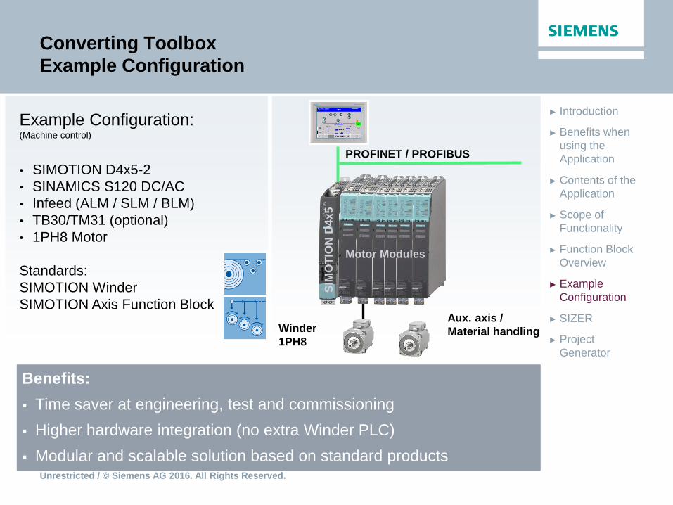
Example Configuration
Benefits:
Time saver at engineering, test and commissioning
Higher hardware integration (no extra Winder PLC)
Modular and scalable solution based on standard products
SIM
OT
ION
D4x
5
Motor Modules
PROFINET / PROFIBUS
Winder
1PH8
Aux. axis /
Material handling
Example Configuration: (Machine control)
• SIMOTION D4x5-2
• SINAMICS S120 DC/AC
• Infeed (ALM / SLM / BLM)
• TB30/TM31 (optional)
• 1PH8 Motor
Standards:
SIMOTION Winder
SIMOTION Axis Function Block
Unrestricted / © Siemens AG 2016. All Rights Reserved.
► Project
Generator
► SIZER
► Example
Configuration
► Function Block
Overview
► Scope of
Functionality
► Contents of the
Application
► Benefits when
using the
Application
► Introduction
Converting Toolbox
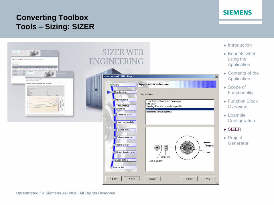
Tools – Sizing: SIZER

Unrestricted / © Siemens AG 2016. All Rights Reserved.
► Project
Generator
► SIZER
► Example
Configuration
► Function Block
Overview
► Scope of
Functionality
► Contents of the
Application
► Benefits when
using the
Application
► Introduction
Converting Toolbox
Converting module for Project Generator
• Assisted configuration
• Generation of a machine project incl. control sequence
• SIMOTION Project Generator
https://support.industry.siemens.com/cs/de/en/view/51339107
Unrestricted / © Siemens AG 2016. All Rights Reserved.
Thank you for your attention!
Application Center
DF FA PMA APC
Frauenauracher Str. 80
D-91056 Erlangen
E-Mail:
om
siemens.com/answers