Embed Size (px)
Citation preview

SIMOTICS 1LE0 Low-voltage Motors

Contents
1.Overview The 1LE0 series of high efficiency 3 phase asynchronous motors with cast iron housing is Totally Enclosed Fan
Cooled (TEFC) with IP55 environmental protection, and applicable for general purpose use. These motors are
designed and manufactured in accordance with ISO, IEC standards, GB standards. By switching to 1LE0 series motor,
customer can save energy up to 10 %!
The 1LE0 series motor is designed for constant or adjustable speed with continuous duty operation (S1) over a speed
range.
Features of Siemens 1LE0 series
■ Frame and connection box material: grey cast iron.
■ Standard color: stone grey (RAL 7030)
■ Available in 2, 4, 6 pole variants with efficiency grade 2. according to GB18613-2006 and efficiency class IE2
according to IEC 60034-30.
■ Rated power range: 0.55 kW ~ 315 kW at 50 Hz.
■ Optimized compact style construction.
■ Standard mounting construction according to IEC 60034-7: IM B3, IM B5, IM B35 and etc.
■ All motors are designed to IP55 degree of protection (IEC 60034-5) .
■ Re-greasing devices for FS1)
280 ~ 355 as standard, and for FS100 ~ 250 as option.
■ Reinforced bearings for increased cantilever forces for FS100 ~ 355 as option.
■ Winding protections with PTC, PT100 and KTY84-130 as option.
■ Terminal box on top, and cable entry on right side (viewed from driven end). Variable location of connection
boxes and cable entries as option.
■ Insulation system is designed for temperature class 155 (F). At rated output with line-fed operation, the motors
can be used in temperature class 130 (B).
■ Self ventilated motors with radial-flow fans (cooling method IC 411 according to IEC 60034-6) as standard,
forced air cool with external separately driven fans as option.
■ FS 80 ~ 90 motor donot have eyebolt; FS 100 ~ 315 all motors have 2 eyebolts, and FS 355 motor have one
eyebolt for transport.
Note: 1)
FS,Frame Size
Environmental
■ Degrees of motor protection IP55 (IEC 60034-5).
■ Altitude shall not exceed 1000m above sea-level (IEC 60034-1).
■ Allowed air temperature between -20 ºC and 40 ºC (IEC 60034-1).
■ Permitted relative humidity:
-20 ºC _ T _ 20 ºC:100 %
20 ºC < T _ 30 ºC:95 %
30 ºC < T _ 40 ºC:55 %
For higher coolant temperatures and / or site altitudes higher than 1000 m above sea level, the specified motor output
must be reduced by using the factor kHT. The results in an admissible output (Padm) of the motor:
Padm = Prated • kHT

Factor kHT for different side altitudes and / or coolant temperature
Site altitude above see level Site altitude above see level Coolant temperature
< 30ºC 30 ~ 40ºC 45ºC 50ºC 55ºC 60ºC
1000 m 1.07 1.00 0.96 0.92 0.87 0.82
1500 m 1.04 0.97 0.93 0.89 0.84 0.79
2000 m 1.00 0.94 0.90 0.86 0.82 0.77
2500 m 0.96 0.90 0.86 0.83 0.78 0.74
3000 m 0.92 0.86 0.82 0.79 0.75 0.70
3500 m 0.88 0.82 0.79 0.75 0.71 0.67
4000 m 0.82 0.77 0.74 0.71 0.67 0.63
2. Reference standards
The 1LE0 complies with the following electrical and mechanical standards:
Title IEC standard
Rotating electrical machines – Part 1: Rating and performance IEC 60034-1
Rotating electrical machines – Part 2-1: Standard methods for determining losses and
efficiency from tests (excluding machines for traction vehicles) IEC 60034-2
Rotating electrical machines – Part 5: Degrees of protection provided by the integral design
of rotating electrical machines (IP code) - Classification IEC 60034-5
Rotating electrical machines – Part 6: Methods of cooling (IC Code) IEC 60034-6
Rotating electrical machines – Part 7: Classification of types of construction, mounting arrangements and terminal box position (IM Code)
IEC 60034-7
Rotating electrical machines – Part 8: Terminal markings and direction of rotation IEC 60034-8
Rotating electrical machines – Part 9: Noise limits IEC 60034-8
Rotating electrical machines – Part 14: Mechanical vibration of certain machines with shaft
heights 56 mm and higher – Measurement, evaluation and limits of vibration severity IEC 60034-14
Rotating electrical machines – Part 1: Frame numbers 56 to 400 and flange numbers 55 to
1080 IEC 60072-1
Electrical insulation – Thermal classification IEC 60085
Classification of environmental conditions Part 2-1: Environmental conditions appearing in
nature – Temperature and humidity IEC 60721-2-1
Standard voltages IEC 60038
Nameplate
1 Three-phase Low-voltage motor
2 Order No.
3 Series number
4 Type of construction
5 Degree of protection
6 Rated voltage and Winding
connections
7 Frequency [Hz]
8 Rated output [kW]
9 Rated current [A]
10 Efficiency
11 Power factor [cosφ]
12 Rated speed
13 Thermal class
14 Bearing at the drive end
15 Grease type
16 Re-grease interval
17 Standards
18 Quantity
19 Bearing at the non-drive end
20 GB standard 21 Net weight
22 Efficiency grade
23 Frame size
24 Balance method

3.Mechanical design
Connection box
The connection box made of cast iron is located on the top of motor housing as standard, and can be rotated by 4×90
º to allow for cable entry from each direction. All the connection box have 2 cable entries, one is sealed by the cable
gland, and another sealed by screwed plug.
Connection boxes technical data
Frame
Size
Number of
terminals
Contact screw
thread
Max. connectable
cross-section(mm2)
Outer cable diameter
(sealing range)(mm)
Cable entry size
(Gland+Screwed plug)
80 6
M4
1.5 13~18 M25 1.5+M16 1.5 90 6
100 6 4
18~25 M32 1.5+M32 1.5 112 6
132 6 6
160 6 M5 16 22~32 M40 1.5+M40 1.5
180 6
200 6 M6 25 32~38 M50 1.5+M50 1.5
225 6 M8 35
250 6 M10 120
37~44 M63 1.5+M63 1.5 280 6
315 6 M12 240
355 6 M20 44~57 M72 2+M63 2
Location of the connection box
Besides standard position, the connection box also can be on the right or left of motor housing.
The position of terminal box can be indicated on the 16th
digit of motor order code.
The position of connection box is described by viewed from drive end (DE).
■ On top (Standard), 16th position of Motor Order No. digit 4.
■ On RHS, 16th position of Motor Order No. digit 5.
■ On LHS, 16th position of Motor Order No. digit 6.
If there is interfere between the connection box and other components, the connection box can
be moved from the drive end (DE) to non-drive end (NDE) (Option code: H08).

Cable entry on connection box
Unless stated, otherwise the cable entry is located in the standard position as show in the
following illustration. The connection box can also be rotated such that the cable entry is
located.
■ Towards the drive end (DE)
Rotation of connection box by 90°, entry from DE, Option code R10. For flange motor (IM B5) from FS80 to
FS100, only possible with connection box on NDE (Option code H08).
■ Towards the non-drive end (NDE)
Rotation of connection box by 90°, entry from NDE, Option code R11.
■ Towards the left side (opposite to Standard)
Rotation of connection box by 180°, entry from opposite end, Option code R12.
If the position of the connection box (connection box RHS or LHS) is changed, the position of
the cable entry must be checked. If necessary, it can be ordered with the corresponding order
codes (R10, R11 and R12).
Construction and mounting type
Construction type With feet and without flange on the end-shield (DE)
Mounting type IM B3 FS 80 ~ 355 IM B6 FS 80 ~ 315 IM B7 FS80 ~ 315 IM B8 FS 80 ~ 315 IM V51) FS 80 ~ 315 IM V6 2) FS 80 ~ 315
Diagram
Letter, position
14th
of Motor code A T U V C D
Construction type Without feet and with flange on the end-shield (DE) With feet and with flange on the end-shield (DE)
Mounting type IM B5 FS 80 ~ 315 IM V11)FS 80~355 IM V3 2)FS 80~315 IM B35 FS 80~355 IM V15 1)FS 80 ~ 315 IM V35 2)FS 80 ~ 315
Diagram
Letter, position
14th
of Motor code F G H J W Y
Construction type Without feet and with C-flange on the end-shield (DE)
Mounting type IM B14 FS 80 ~ 160 IM V18 1)
FS 80 ~ 160 IM V19 2)
FS 80 ~ 160
Diagram
Letter, position
14th
of Motor code K L M
Note:
1) At outdoor application, the using of protective cover (Option code H00) is recommended
2) At out door application the protection of shaft again jet-water is Recommended
Cooling and ventilation
The 1LE0 standard motors are fitted with an radial flow fan for cooling in accordance with IEC
60034-6 cooling method.
For some special application, separately driven fan should be considered to be configurated.
■ The use of a separately driven fan is recommended to increase motor utilization at low speed;
■ When motor speed significantly higher than the synchronous speed, the separately fan is also recommended
to be used. It can help reduce the motor noise.
The separately driven fan can be supplied already fitted, Option code F70. When the separately
driven fan is mounted, the length of the motor increase by _L.
Technical data of separately driven fan

Motor frame size Voltage (V) Frequency
(Hz)
Rated
output (W)
Current
Noise (A)
Speed(rpm) Fan power
(m3/h)
Fan pressur
(Pa) Δ L(mm)
80 380 50 30 0.08 2400 330 60 105
90 380 50 52 0.2 2800 390 60 124
100 380 50 52 0.2 2800 600 70 127
112 380 50 52 0.2 2800 800 80 139
132 380 50 40 0.1 2400 1000 70 146
160 380 50 80 0.23 1400 1000 50 130
180 380 50 80 0.23 1400 1200 55 132
200 380 50 230 0.71 1400 1800 65 168
225 380 50 230 0.71 1800 65 174
250 380 50 230 0.71 1400 3300 85 175
280 380 50 230 0.71 1400 4000 110 236
315 380 50 370 1.1 1250 6200 180 266
355 380 50 550 1.8 1350 7000 180 270
Bearing system
1LE0 series motors are supplied with the ball bearing as standard.These bearings are either of
the sealed or regreasable type.
For FS80 ~ 132, the floating bearings are assembled; for FS160 ~355, floating bearing at DE,
and fixed bearing at NDE assembled.
The standard bearing can endure a maximum cantilever force,referred to page 11 - Permissible
cantilever forces. If higher cantilever force on the shaft required, the increased cantilever
bearing design (Option code: L22) should be considered.
As standard, FS80 ~ 250 motors are not with regreasing device,but FS280 ~ 355 motors with
regreasable bearing and regreasing device. If necessary, FS100 ~ 250 motor can be configured
with regreasable bearing and regreasing device (Option code: L23).
Bearing Assignment Frame
size Pole 1LE0 Standard design
Increased cantilever-bearing
(Option code: L22)
Re-greasing bearing
(Option code: L23)
DE bearing NDE bearing
(Horizontal
mounting)
NDE bearing
(Vertical
mounting)
DE bearing NDE
bearing
(Horizontal
mounting)
NDE
bearing
(Vertical
mounting)
DE
bearing
NDE
bearing
80 2, 4, 6,8 62042Z J C3 62042Z J C3 62042Z J C3 - - - - -
90 2, 4, 6,8 62052Z J C3 62052Z J C3 62052Z J C3 - - - - -
100 2, 4, 6,8 62062Z J C3 62062Z J C3 62062Z J C3 63062Z J C3 62062Z J C3 62062Z J C3 6206 J C3 6206 J C3
112 2, 4, 6,8 62062Z J C3 62062Z J C3 62062Z J C3 63062Z J C3 62062Z J C3 62062Z J C3 6206 J C3 6206 J C3
132 2, 4, 6,8 62082Z J C3 62082Z J C3 62082Z J C3 63082Z J C3 62082Z J C3 62082Z J C3 6208 J C3 6208 J C3
160 2, 4, 6,8 62092Z J C3 62092Z J C3 62092Z J C3 63092Z J C3 62092Z J C3 62092Z J C3 6209 J C3 6209 J C3
180 2, 4, 6,8 62102Z J C3 62102Z J C3 62102Z J C3 NU210 63102Z J C3 63102Z J C3 6210 J C3 6210 J C3
200 2, 4, 6,8 6212 Z J C3 6212 Z J C3 6212 Z J C3 NU212 6212 Z J C3 6212 Z J C3 6212 J C3 6212 J C3
225 2, 4, 6,8 6213 Z J C3 6213 Z J C3 6213 Z J C3 NU213 6213 Z J C3 6213 Z J C3 6213 J C3 6213 J C3
250 2, 4, 6,8 6215 J C3 6215 J C3 7215 NU215 6215 J C3 7215 6215 J C3 6215 J C3
280 2, 4, 6,8 6317 J C3 6317 J C3 7317 NU317 6317 J C3 7317 - -
315 2, 4, 6,8 6319 J C3 6319 J C3 7319 NU319 6319 J C3 7319 - -
355 2 6319 J C3 6319 J C3 7319 NU319 6319 J C3 7319 - -
,4, 6,8 6322 J C3 6322 J C3 7322 NU322 6322 J C3 7322 - -
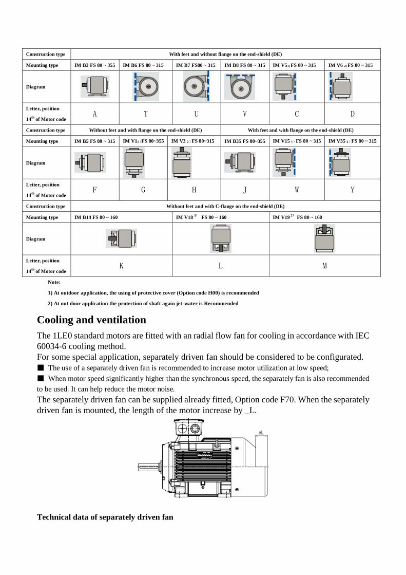
Bearing life time (nominal lifetime)
The nominal bearing lifetime is defined according standardized calculation procedures (ISO
281) and is reached or even exceeded for 90% of the bearings when the motors are operated in
compliance with the data provide in the catalog. Generally, the bearing lifetime is defined by
the bearing size, the bearing load, the operating condition, the speed and the grease lifetime.
The bearing lifetime of motors with horizontal type of construction is at least 40,000 hours if
there is no additional axial loading at the coupling output and at least 20,000 hours with the
maximum admissible loads. This assumes that the motor is normally operated at 50Hz.
When the motor runs outside of normal conditions, the bearing life will be reduced, such as the
following conditions.
■ When the motor runs beyond the rated speed, the increase of motor vibration will result in the extra radial
and axial force on bearing. This will reduce the life of bearing;
■ When the motor vibration increase due to the environment or other equipment, the bearing also will endure
more radial and axial force. This also will reduce the life of bearing;
■ If the coolant temperature is increased by 10 ºC, the grease lifetime and regreasing interval is halved.
Grease life and re-greasing interval
For permanent lubrication, the bearing grease lifetime is matched to the bearing lifetime. This can,
however, only be achieved if the motor is operated in accordance with the catalog specifications.
For motors which can be regreased at defined regreasing intervals, the bearing lifetime can be
extended and/or unfavorable factors such as temperature, mounting conditions, speed, bearing size and
mechanical load can be compensated.
Grease life (Horizontal installation)
Frame size Poles Grease lifetime up to CT 40 ºC 1)
Grease for permanent lubrication bearing
80 ~ 250 2, 4, 6 20000 or 40000 2)
Grease for regreasable bearing
100 ~ 160 2, 4, 6 8000(h)
180 ~ 250 2 4000(h)
180 ~ 250 4, 6 8000(h)
280 ~ 315 2 3000(h)
280 ~ 315 4, 6 5000(h)
355 2 2000(h)
355 4, 6 4000(h)
Note:
1) If the coolant temperature is increased by 10 K, the grease lifetime and regreasing interval are halved.
2) 40000 hours apply to horizontally installed motors with coupling output without additional axial loads.
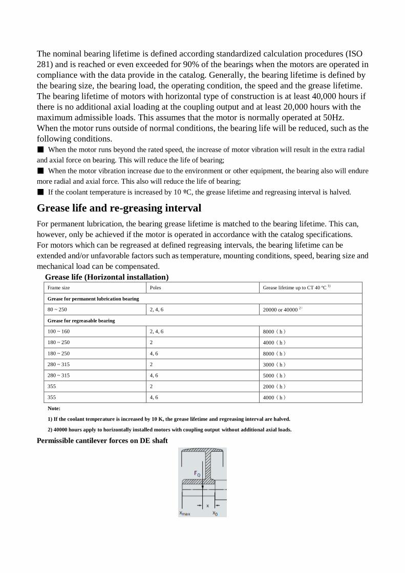
Permissible cantilever forces on DE shaft

In order to calculate the admissible cantilever forces for a radial load, the line of force (i.e. the
centerline of the pulley) of the cantilever force FQ(N) must lie within the free shaft extension
(dimension x).Dimension x [mm] is the distance between the point of application of force FQ and the
shaft shoulder. Dimension xmax. Corresponds to the length of the shaft extension. Total cantilever force
is calculated using the following equation.
FQ = c • FU
The pre-tension factor c is a value gained from experience from the belt manufacturer. The following
approximate value can be assumed.
■ For normal flat leather belts with an idler pulley, c = 2.
■ For v-belts, c = 2 to 2.5.
■ For special synthetic belts (depending on the type and load),
c = 2 to 2.5.
The circumferential force FU (N) is calculated using the following equation.
FU circumferential force in N
P rated motor power (transmitted power) in kW
n rated motor speed
D pulleys in mm.
The table below contains the permissible Radial Force values in Newtons with the assumption of zero axial forces.
Admissible cantilever forces for standard version Bearing design for increased cantilever forces (Option code: L22)
Frame Size Number
of poles Admissible cantilever force
1) Frame Size
Number
of poles Admissible cantilever force
1)
for x0 N for xmax N for x0 N for xmax N
80M
2 620 510
80M
2 -2) -2)
4 790 640 4 -2) -2)
6 910 740 6 -2) -2)
90S
90L
2 700 560 90S
90L
2 -2) -2)
4 880 720 4 -2) -2)
6 1,020 820 6 -2) -2)
100L 2 980 790 100L 2 1,480 1,220
4 1,230 990 4 1,870 1,540
6 1,420 1,140 6 2,140 1,720
112M 2 980 790 112M 2 1,480 1,220
4 1,230 990 4 1,870 1,540
6 1,420 1,140 6 2,140 1,720
132S
132M
2 1,440 1,120 132S
132M
2 2,100 1,700
4 1,820 1,420 4 2,720 2,170
6 2,080 1,630 6 3,100 2,420
160M
160L
2 1,560 1,240 160M
160L
2 2,650 2,120
4 1,970 1,570 4 3,300 2,600
6 2,260 1,800 6 3,750 2,900
180M
180L
2 1,820 1,470 180M
180L
2 3,300 2,700
4 2,300 1,900 4 4,200 3,400

6 2,630 2,150 6 4,750 3,900
200L 2 2,650 2,230 200L 2 5,000 4,200
4 3,350 2,800 4 6,330 5,320
6 3,850 3,230 6 7,250 6,080
225S
225M
2 3,000 2,540 225S
225M
2 5,650 4,800
4 3,700 3,000 4 6,950 5,600
6 4,250 3,470 6 7,900 6,500
250M 2 3,150 2,620 250M 2 6,700 5,600
4 3,950 3,280 4 8,500 7,000
6 4,600 3,820 6 9,500 7,800
280S
280M
2 6,600 5,550 280S
280M
2 11,500 9,500
4 8,300 6,950 4 17,000 14,000
6 9,650 8,120 6 20,000 17,000
315S
315M
315L
2 7,100 6,200 315S
315M
315L
2 14,600 12,300
4 8,700 7,250 4 20,000 16,500
6 10,000 8,500 6 23,000 19,000
355M
355L
2 6,800 6,000 355M
355L
2 15,800 14,000
4 11,500 10,000 4 22,000 19,000
6 13,200 11,600 6 25,000 22,000
Note:
1) It should be considered that for types of construction IM B6, IM B7, IM B8, IMV5 and IM V6 the belt tension is only permitted to act
parallel to the mounting plane or towards the mounting plane and the feet must be supported. Both feet must be secured for foot-mounting
types of construction.
2) Reinforced version only from FS100 ~ 355
Noise levels
Noise levels for mains-fed operation
The noise levels are measured in accordance with DIN EN ISO 1680 in a dead room. It is specified as
the A-valued measuringsurface sound pressure level Lpfa in dB (A). This is the spatial mean value of
the sound pressure levels measured on the measuring surface. The measuring surface is a cube 1 m
away from the motor surface. The sound power level is also specified as LWA in dB (A).
The following specified values are only valid for no load at 50 Hz, and the tolerance is +3 dB. While
motor operating 60 Hz with no load, the values are approximately +4 dB (A) higher.
Output(kW)
synchronous speed(r/min)
Lpfa / LWA ( dB(A))
3000(2 poles) 1500(4 poles) 1000(6 poles)
0.55 - 45 / 57 44 / 56
0.75 53 / 65 45 / 57 48 / 60
1.1 53 / 65 47 / 59 48 / 60
1.5 60 / 72 47 / 59 52 / 64
2.2 60 / 72 55 / 67 54 / 66
3 62 / 74 55 / 67 56 / 69
4 63 / 75 55 / 67 56 / 69

5.5 66 / 79 57 / 70 56 / 69
7.5 66 / 79 57 / 70 60 / 73
11 67 / 80 60 / 73 60 / 73
15 67 / 80 60 / 73 61 / 74
18.5 67 / 80 61/ 74 65 / 78
22 69 / 82 61/ 74 65 / 78
30 71 / 84 63 / 76 65 / 79
37 71 / 84 63 / 77 65 / 79
45 74 / 88 63 / 77 65 / 79
55 74 / 88 64 / 78 65 / 79
75 74 / 88 66 / 80 66 / 80
90 76 / 90 66 / 80 66 / 80
110 78 / 92 69 / 83 68 / 82
132 78 / 92 69 / 83 68 / 83
160 81 / 95 69 / 83 72 / 87
200 81 / 95 74 / 88 75 / 90
220 86 / 101 82 / 97 75 / 90
250 86 / 101 82 / 97 -
280 88 / 103 85 / 100 -
315 88 / 103 85 / 100 -
Note:
Lpfa – sound pressure level
LWA – sound power level
Vibration
1LE0 rotors are dynamically balanced to severity grade A using a half key.Table below contains the
effective vibration values for unloaded motors.
Vibration grade Frame size (mm) 56 _ FS _ 132 160 _ FS _ 280 280 < FS _ 355
A Mounting Vibration velocity(mm/s) Vibration velocity(mm/s) Vibration velocity(mm/s)
Free suspension 1.6 2.2 2.8
Rigid mounting 1.3 1.8 2.3
4.Electrical design
Rated Output
1LE0 series motors rated output powers means that the motor runs under continuous duty S1 (IEC
60034 - 1) operation when operated at ambient temperature from -20 ºC to 40 ºC and at altitudes of up
to 1000 m over sea.
Voltage and Frequency
IEC 60034-1 differentiates between Category A (combination of voltage deviation ±5 % and
frequency deviation ±2 %) and Category B (combination of voltage deviation ±10 % and frequency
deviation +3 % / -5 %) for voltage and frequency fluctuations. The motors can supply their rated torque

in both Category A and B. In Category A, the temperature rise is approximately 10 K higher than
during normal operation.
Standard Category Category
60034 - 1 A B
Voltage deviation 5 % ±10 %
Frequency deviation 2 % +3 % / -5 %
According to the standard, longer operation is not recommended for Category B.
Tolerance for electrical data
■ Efficiencyηat
Prated _ 150 kW: - 0.15 x (1 – η)
Prated > 150 kW: - 0.10 x (1 – η)
With η being a decimal number
■ Power factor - (1 – cosφ) / 6
Minimum absolute value: 0.02
Maximum absolute value: 0.07
■ Slip ±20 % (for motors < 1 kW ±30 % is admissible)
■ Locked-rotor current +20 %
■ Locked-rotor torque -15 % to +25 %
■ Breakdown torque -10 %
■ Moment of inertia ±10 %
Overload times
According to IEC60034, 1LE0 series motors are designed to withstand overload capacity of 1.5 times
rated current for 2 minutes at rated voltage and frequency.
Insulation system
The insulation system of 1LE0 results in high reliability, a long service life and high resistance to stress,
for example, during starting or under overload conditions.
1LE0 series motors are designed for temperature class 155 (F). At rated output with line-fed operation,
the motors can be used in temperature class 130 (B).
Motor protection
Motor thermal overload protection
Motor thermal protection means to use of thermal protectors and thermal detectors incorporated into
the stator windings or placed in other suitable positions in motor in order to protect them against
serious damage due to thermal overloads.
The order variants for motor protection are coded with letters in the 15th position of the Motor Order
No., or ordered with Option code. Some protection method about winding protection and bearing
protection are shown in the following.
Winding protection
■ PTC thermistors protection

The most comprehensive protection against thermal overloading of the motor is provided by PTC
thermistors (thermistor motor protection) installed in the motor winding. The temperature of the
winding can be accurately monitored thanks to its lowheating capacity and the excellent heat contact
with the winding. When a limit temperature is reached (nominal tripping temperature), the resistance
of PTC thermistors will have a step change. This is evaluated by a tripping unit and can be used to open
auxiliary circuits.
The PTC thermistors themselves cannot be subjected to high currents and voltages. This would result
in destruction of the semiconductor. The switching hysteresis of the PTC thermistor and tripping unit
is low, which supports fast restarting of the drive.
Motors with this type of protection are recommended for heavy duty starting, switching duty, extreme
changes in load, high ambient temperatures or fluctuating supply systems.
2 alternatives of PTC protection
- Motor winding is protected with PTC thermistors with 3 embedded temperature sensors for tripping.
Connection be done through 2 auxiliary terminals in the connection box. 15th position of Motor Order No. letter
B.
- Motor winding is protected with two sets of three temperature sensors, one set is for warning, another set for
tripping. The warning temperature is 145 ºC, and tripping temperature is 155 ºC. Connection be done through 4
auxiliary terminals in the connection box. 15th position of Motor Order No. letter C.
■ KTY84-130 temperature sensor protection
When 1LE0 with converter fed operation, KTY84-30 is recommended to be configured for winding protection.
The following chart show the characteristic of KTY84-30.

KTY84-130 sensor characteristics curve
Some converters from Siemens determine the motor temperature using the resistance of the temperature sensor.
They can be set to a required temperature for alarm and tripping.
1LE0 Motor winding with embedded temperature detector sensor KTY 84-130. Two auxiliary terminals are
provided in the connection box. 15th position of Motor Order No. letter F.
■ PT100 resistance thermometers protection
PT100 thermometers are a high precision, high sensitivity, better linear temperature resistance, more stable
performance, and high reliability sensor, whose characteristics are as following.
2 alternatives of PT100
- Installation of 3 PT100 resistance thermometers. Connection be done through 6 auxiliary terminals in the
connection box. 15th position of Motor Order No. letter H.
- Installation of 6 PT100 resistance thermometers. Connection be done through 12 auxiliary terminals in the
connection box. 15th position of Motor Order No. letter J.
Bearing protection
1LE0 series motors bearings have no protection as standard. For some severe application, such as high load,
high coolant temperature and etc., the bearing is recommended to be protected. The bearing is protected through
thermometers screwed into the bearing plates of motor driven end (DE) and non-drive-end (NDE). The wires
are routed through the main connection box.
Installation of 2 PT100 screwed-in resistance thermometers for 1LE0 motor bearings, Option code: Q5A.
Connection be done through 4 auxiliary terminals in the connection box.

Anti-condensation heater
Motors whose windings are at risk of condensation due to the climatic conditions, e.g. inactive motors in humid
atmospheres or motors that are subjected to widely fluctuating temperatures can be equipped with
anti-condensation heaters (Option code: Q04).
Anti-condensation heaters must be switched off during operation. When motor shut down, the heaters must be
switched on.
Electrical data of Anti-condensation heater Frame size Spaces heater type Power(W) Vlotage(V)
80~90 KBQ302A 20 220
100~112 KBQ303A 30 220
132~160 KBQ304A 40 220
180~200 KBQ305A 50 220
225~280 KBQ306A 60 220
315 KBQ308A 80 220
355 KBQ310A 100 220
5.Converter fed application 1LE0 series motors are suitable for pumps, fans, compressors, texitle machine and mechanical machine
applications where variable or constant speed is required.
In application where the motor is driven by a converter, the degree of electrical interference depends on the type
of converter used (type, number of IGBTs, interference suppression measures, and manufacturer), cabling,
distance and application requirements. The installation guidelines of the converter manufacturer with regards to
electromagnetic compatibility must be considered at all times during the design and implementation phases.
At rated output with converter fed operation, the motors will be used in temperature class 155 (F). To prevent
damage as a result of bearing currents, insulated bearings are recommended to be assembled for frame size 250
and above. Please inquire Siemens about the detailed information of insulated bearing.
Converter-fed operation
The standard insulation of the 1LE0 series motors is designed such that operation is possible on the converter at
mains voltage up to 460 V.
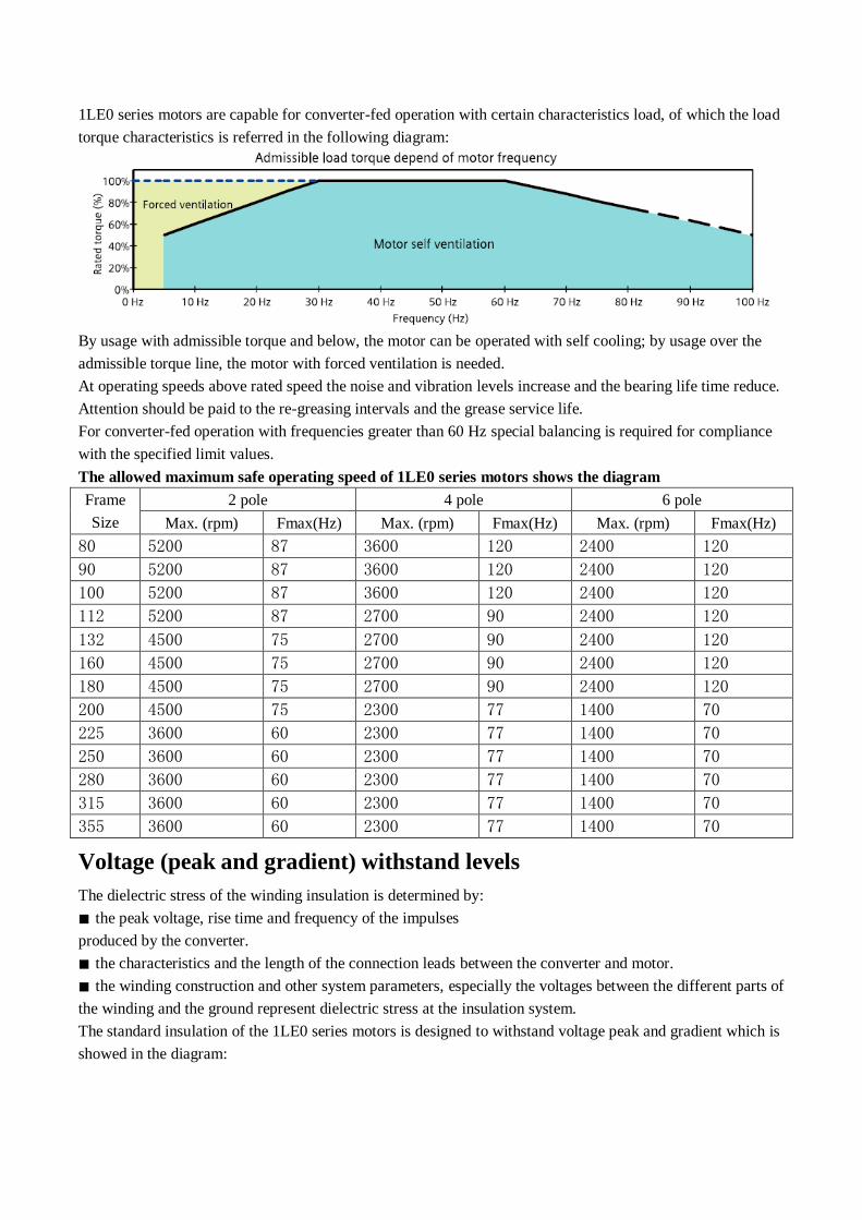
1LE0 series motors are capable for converter-fed operation with certain characteristics load, of which the load
torque characteristics is referred in the following diagram:
By usage with admissible torque and below, the motor can be operated with self cooling; by usage over the
admissible torque line, the motor with forced ventilation is needed.
At operating speeds above rated speed the noise and vibration levels increase and the bearing life time reduce.
Attention should be paid to the re-greasing intervals and the grease service life.
For converter-fed operation with frequencies greater than 60 Hz special balancing is required for compliance
with the specified limit values.
The allowed maximum safe operating speed of 1LE0 series motors shows the diagram
Frame
Size
2 pole 4 pole 6 pole
Max. (rpm) Fmax(Hz) Max. (rpm) Fmax(Hz) Max. (rpm) Fmax(Hz)
80 5200 87 3600 120 2400 120
90 5200 87 3600 120 2400 120
100 5200 87 3600 120 2400 120
112 5200 87 2700 90 2400 120
132 4500 75 2700 90 2400 120
160 4500 75 2700 90 2400 120
180 4500 75 2700 90 2400 120
200 4500 75 2300 77 1400 70
225 3600 60 2300 77 1400 70
250 3600 60 2300 77 1400 70
280 3600 60 2300 77 1400 70
315 3600 60 2300 77 1400 70
355 3600 60 2300 77 1400 70
Voltage (peak and gradient) withstand levels
The dielectric stress of the winding insulation is determined by:
■ the peak voltage, rise time and frequency of the impulses
produced by the converter.
■ the characteristics and the length of the connection leads between the converter and motor.
■ the winding construction and other system parameters, especially the voltages between the different parts of
the winding and the ground represent dielectric stress at the insulation system.
The standard insulation of the 1LE0 series motors is designed to withstand voltage peak and gradient which is
showed in the diagram:

The values refer to standard IEC 60034-17.
6. Order No. FS 080 ~ 355

Foot note:
1) Order other voltages with voltage code 90 and the corresponding Option code (see under "Option") .
2) The types of construction IM B6/7/8, IM V6 and IM V5 without protective cover are also possible as long as
no condensation drainage holes (Order code: H03) and no stamping of these types of construction on the rating
plate are required. As standard, the type of construction IM B3 is then stamped on the rating plate.
3) The type of construction is stamped on the rating plate. When ordering with condensation drainage holes
(order code H03), it is absolutely necessary to specify the type of construction for the exact position of the
condensation drainage holes during manufacture.
4) The types of construction IM V1 and IM V3 without protective cover are also possible as long as no
condensation drainage holes (Order code: H03) and no stamping of these types of construction on the rating
plate are required. As standard, the type of construction IM B5 is then stamped on the rating plate.
5) The types of construction IM V19 and IM V18 without protective cover are also possible as long as no
condensation drainage holes (Order code: H03) and no stamping of these types of construction on the rating
plate are required. As standard, the type of construction IM B14 is then stamped on the rating plate.
6) For motor with IM B5, IM V1, IM V3, IM B14, IM V18 and IM V19 construction and mounting type, the
16th digit of motor order No. must be "4";
7) Only for FS080 ~ 160.
8) Without canopy, for protective cover with canopy needed Option code H00.
Order No. example:
Low voltage three phase high efficiency motor 4-pole, 15 kW, IM B5, 380VD/660VY 50 Hz, IP55, connection
box on top and cable entry at right side (view from DE), with separately driven fan.
Motor order code: 1LE0001-1DB43-3FA4-Z F70
Motor order code introduction:
7.Technical data table
tab 1

Frame
Size Order No.
Rated
Output
Rated
Speed
Efficiency according to IEC 60034-30
(IE2) Rated
torque
Starting
Current
Starting
torque Max
torque
Weight
IMB3
Effeciency at
(50 HZ)%
Power
factor
Rated
current
For direct-on-line starting as
multiple of the rated
KW rpm 4/4 load 3/4load cosΦ A Nm Kg
3000rpm 2 pole 220VD/380VY 50 HZ
80M 1LE0001-0DA22-1… 0.75 2795 77.4 78.5 0.84 1.75 2.6 5.6 2.4 2.4 15.5
80M 1LE0001-0DA32-1… 1.1 2835 79.6 80.6 0.84 2.50 3.7 6 2.8 3.2 17.5
90S 1LE0001-0EA02-1… 1.5 2890 81.3 81.7 0.84 3.35 5.0 6.5 2.4 3.1 23
90L 1LE0001-0EA42-1… 2.2 2890 83.2 83.7 0.85 4.75 7.3 7.2 2.6 3.5 26
100L 1LE0001-1AA42-1… 3 2885 84.6 85.1 0.84 6.4 9.9 7.5 4 4.5 34
3000rpm 2 pole 380VD/660VY 50 HZ
112M 1LE0001-1BA23-3… 4 2930 85.8 86.6 0.86 8.2 13.0 7.5 2.2 2.9 40
132S 1LE0001-1CA03-3… 5.5 2930 87 87.6 0.87 11.0 17.9 7.5 2.2 2.9 56
132S 1LE0001-1CA13-3… 7.5 2930 88.1 88.8 0.89 14.5 24.4 7.5 2.3 2.9 62
160M 1LE0001-1DA23-3… 11 2935 89.4 90.1 0.86 21.5 35.8 7.5 2.2 2.9 96
160M 1LE0001-1DA33-3… 15 2935 90.3 91 0.86 29.5 48.8 7.5 2.4 3.2 106
160L 1LE0001-1DA43-3… 18.5 2935 90.9 91.7 0.89 34.5 60.2 7.5 2.4 3.2 125
180M 1LE0001-1EA23-3… 22 2935 91.3 91.8 0.87 42.0 71.6 7.6 2.5 3.2 152
200L 1LE0001-2AA43-3… 30 2955 92 92.3 0.86 58 97.0 7.5 2.5 3.2 229
200L 1LE0001-2AA53-3… 37 2955 92.5 92.8 0.88 69 119.6 7.5 2.5 3.2 245
225M 1LE0001-2BA23-3… 45 2965 92.9 93.1 0.88 84 144.9 7.9 2.5 3.1 307
250M 1LE0001-2CA23-3… 55 2970 93.2 93.2 0.88 102 176.9 7.5 2.5 3 378
280S 1LE0001-2DA03-3… 75 2975 93.8 93.8 0.87 140 240.8 7.5 2.8 3 550
280M 1LE0001-2DA23-3… 90 2978 94.1 94.1 0.87 167 288.6 7.5 3 3.1 570
315S 1LE0001-3AA03-3… 110 2982 94.3 94.3 0.90 197 352.3 7.5 2.2 2.6 740
315M 1LE0001-3AA23-3… 132 2982 94.6 94.6 0.91 235 422.7 7.5 22.3 2.9 855
315L 1LE0001-3AA53-3… 160 2982 94.8 95.1 0.92 280 512.4 7.5 2.5 2.8 970
315L 1LE0001-3AA63-3… 185 2982 95 95.3 0.92 320 592.5 7.5 2.5 2.8 1080
315L 1LE0001-3AA73-3… 200 2982 95 95.3 0.92 350 640.5 7.5 2.5 2.8 1090
355M 1LE0001-3BA23-3… 220 2980 95 95 0.90 390 705.0 7.1 2 2.2 1600
355M 1LE0001-3BA33-3… 250 2980 95 95 0.90 445 801.2 7.1 2 2.2 1650
355L 1LE0001-3BA53-3… 280 2980 95 95.1 0.90 500 897.3 7.1 2 2.2 1830
355L 1LE0001-3BA63-3… 315 2980 95 95.1 0.90 560 1009.5 7.1 2 2.3 1840
tab 2
Fram
e
Size Order No.
Rated
Output
Rated
Speed
Efficiency according to IEC 60034-30
(IE2) Rated
torque
Starting
Current
Starting
torque
Max
torque
Weight
IMB3
Effeciency at
(50 HZ)%
Power
factor
Rated
current
For direct-on-line starting as
multiple of the rated
KW rpm 4/4 load 3/4load cosΦ A Nm Kg
1500rpm 4 pole 220VD/380VY 50 HZ
80M 1LE0001-0DB22-1… 0.55 1425 74.0 74.7 0.8 1.40 3.7 6 2 2.7 17.5
80M 1LE0001-0DB32-1… 0.75 1440 79.6 79.6 0.75 1.90 5.0 6.5 2.8 3.5 19
90S 1LE0001-0EB02-1… 1.1 1440 81.4 81.4 0.75 2.75 7.3 7 2.8 3.5 24
90L 1LE0001-0EB42-1… 1.5 1440 82.8 82.8 0.76 3.60 9.9 7 3 3.8 27
100L 1LE0001-1AB42-1… 2.2 1435 84.3 85 0.79 5.0 14.6 7 3 3.2 33

100L 1LE0001-1AB52-1… 3 1435 85.5 86.3 0.79 6.7 20.0 7 3 3.2 37
1500rpm 4 pole 380VD/660VY 50 HZ
112M 1LE0001-1BB23-3… 4 1445 86.6 87.1 0.79 8.9 26.4 7.1 2.7 3.1 45
132S 1LE0001-1CB03-3… 5.5 1460 87.7 88.2 0.79 12.1 36.0 7.5 2.5 3.1 61
132S 1LE0001-1CB23-3… 7.5 1460 88.7 89.4 0.82 15.7 49.1 7.7 2.7 3.2 73
160M 1LE0001-1DB23-3… 11 1465 89.8 90.4 0.84 22.0 71.7 7.5 2.5 3.1 103
160L 1LE0001-1DB43-3… 15 1465 90.6 91.3 0.85 29.5 97.8 7.8 2.7 3.2 130
180M 1LE0001-1EB23-3… 18.5 1465 91.2 91.8 0.85 36.5 120.6 7.3 2.5 3.2 165
180L 1LE0001-1EB43-3… 22 1465 91.6 92.3 0.85 43.0 143.4 7.3 2.4 3.2 180
200L 1LE0001-2AB43-3… 30 1470 92.3 92.9 0.85 58 194.9 7.3 2.7 3.2 238
225S 1LE0001-2BB03-3… 37 1475 92.7 93.2 0.86 71 239.6 7.3 2.7 3.2 298
225M 1LE0001-2BB23-3… 45 1475 93.1 93.5 0.87 84 291.4 7.3 2.7 3.2 322
250M 1LE0001-2CB23-3… 55 1480 93.5 93.9 0.86 104 354.9 7.5 3.1 3.5 410
280S 1LE0001-2DB03-3… 75 1485 94 94.3 0.87 139 482.3 7.5 2.7 3.1 555
280M 1LE0001-2DB23-3… 90 1485 94.2 94.3 0.87 167 578.8 7.5 2.7 3.1 610
315S 1LE0001-3AB03-3… 110 1488 94.5 94.5 0.86 205 706.0 7.3 2.8 2.9 750
315M 1LE0001-3AB23-3… 132 1486 94.7 94.7 0.88 240 848.3 7.3 2.5 2.7 875
315L 1LE0001-3AB53-3… 160 1488 94.9 94.9 0.88 290 1026.9 7.4 3 2.9 960
315L 1LE0001-3AB63-3… 185 1488 95.1 95.1 0.88 335 1187.3 7.4 3 3 1070
315L 1LE0001-3AB73-3… 200 1488 95.1 95.1 0.88 365 1283.6 7.4 3 3 1080
355M 1LE0001-3BB23-3… 220 1490 95.1 95.2 0.90 390 1410.1 6.9 2 2.2 1640
355M 1LE0001-3BB33-3… 250 1490 95.1 95.2 0.90 445 1602.3 6.9 2 2.2 1680
355L 1LE0001-3BB53-3… 280 1490 95.1 95.2 0.90 495 1794.6 6.9 2 2.2 1830
355L 1LE0001-3BB63-3… 315 1490 95.1 95.2 0.90 560 2019.0 6.9 2 2.2 1900
tab 3
Frame
Size Order No.
Rated
Output
Rated
Speed
Efficiency according to IEC 60034-30
(IE2) Rated
torque
Starting
Current
Starting
torque Max
torque Weight
IMB3 Effeciency at
(50 HZ)%
Power
factor
Rated
current
For direct-on-line starting as
multiple of the rated KW rpm 4/4 load 3/4load cosΦ A Nm Kg
1000rpm 6 pole 220VD/380VY 50 HZ
80M 1LE0001-0DC32-1… 0.55 895 71 72 0.76 1.55 5.9 4.5 2.3 2.3 18.5
90S 1LE0001-0EC02-1… 0.75 935 75.9 76.5 0.71 2.10 7.7 5 2.1 2.6 26
90L 1LE0001-0EC42-1… 1.1 945 78.1 78.1 0.71 3.00 11.1 5.5 2.4 2.8 27
100L 1LE0001-1AC42-1… 1.5 945 79.8 80.1 0.74 3.85 15.2 5.5 2.4 2.9 34
112M 1LE0001-1BC22-1… 2.2 950 81.8 82.5 0.73 5.6 22.1 5.5 2.6 3.3 44
132S 1LE0001-1CC02-1… 3 960 83.3 84.3 0.73 7.5 29.8 6 2 2.2 56
1000rpm 6 pole 380VD/660VY 50 HZ
132M 1LE0001-1CC23-3… 4 960 84.6 85.4 0.73 9.8 39.8 6.2 2.2 2.5 66
132M 1LE0001-1CC33-3… 5.5 960 86 86.6 0.75 13.0 54.7 6.4 2.4 2.6 75
160M 1LE0001-1DC23-3… 7.5 965 87.2 87.9 0.77 17.0 74.2 6.4 2.1 2.6 104
160L 1LE0001-1DC43-3… 11 965 88.7 89.4 0.78 24.0 108.9 6.4 2.1 2.6 132
180L 1LE0001-1EC43-3… 15 975 89.7 90.4 0.78 32.5 146.9 6.5 2.3 3 170
200L 1LE0001-2AC43-3… 18.5 975 90.4 91 0.81 38.5 181.2 6.5 2.3 2.8 220

200L 1LE0001-2AC53-3… 22 975 90.9 91.4 0.82 45.0 215.5 6.5 2.3 2.8 240
225M 1LE0001-2BC23-3… 30 980 91.7 92.3 0.83 60 292.3 6.5 2.2 2.8 294
250M 1LE0001-2CC23-3… 37 982 92.2 92.8 0.83 73 359.8 7 2.5 2.8 394
280S 1LE0001-2DC03-3… 45 985 92.7 93.3 0.85 87 436.3 7.5 2.5 2.8 510
280M 1LE0001-2DC23-3… 55 986 93.1 93.7 0.85 106 532.7 7.5 2.5 2.8 535
315S 1LE0001-3AC03-3… 75 986 93.7 94.3 0.85 143 726.4 7.3 2.3 2.8 680
315M 1LE0001-3AC23-3… 90 986 94 94.5 0.85 171 871.7 7.3 2.3 2.8 835
315L 1LE0001-3AC53-3… 110 988 94.3 94.7 0.86 205 1063.3 7.5 2.4 2.8 975
315L 1LE0001-3AC63-3… 132 988 94.6 95 0.86 245 1275.9 7.5 2.5 3 1030
355M 1LE0001-3BC23-3… 160 990 94.8 95.1 0.87 295 1543.4 6.7 1.9 2 1650
355M 1LE0001-3BC33-3… 185 990 95 95.3 0.87 340 1784.6 6.7 1.9 2 1690
355M 1LE0001-3BC43-3… 200 990 95 95.3 0.87 370 1929.3 6.7 1.9 2 1730
355L 1LE0001-3BC53-3… 220 990 95 95.3 0.87 405 2122.2 6.7 1.9 2 1850
355L 1LE0001-3BC63-3… 250 990 95 95.3 0.87 460 2411.6 6.7 1.9 2 1930
8. Options
tab 1
Motor order code Option
Code 1)
Description Application Scope
Voltages and frequency
1LE0001-□□□□2-1□□□ - 220VD / 380VY 50 Hz(0.55 kW ~ 3 kW 2)) FS80 ~ 355
1LE0001-□□□□3-3□□□ - 380VD / 660VY 50 Hz(4 kW ~ 315 kW 2) ) FS80 ~ 355
1LE0001-□□□□2-2□□□ - 230VD / 400VY 50 Hz FS80 ~ 355
1LE0001-□□□□3-4□□□ - 400VD / 690VY 50 Hz FS80 ~ 355
1LE0001-□□□□2-3□□□ - 240VD / 415VY 50 Hz FS80 ~ 355
1LE0001-□□□□0-4□□□ - 400VD 50 Hz FS80 ~ 355
1LE0001-□□□□3-5□□□ - 415VD 50 Hz FS80 ~ 355
1LE0001-□□□□9-0□□□-Z M1A 220VD / 380VY 60 Hz(60 Hz output)60 Hz output FS80 ~ 355
1LE0001-□□□□9-0□□□-Z M1B 380VD / 660VY 60 Hz(60 Hz output)60 Hz output FS80 ~ 355
1LE0001-□□□□9-0□□□-Z M1E 460VY 60 Hz(60 Hz output)60 Hz output FS80 ~ 355
1LE0001-□□□□9-0□□□-Z M1F 460VD 60 Hz(60 Hz output)60 Hz output FS80 ~ 355
Motor protection
1LE0001-□□□□□-□□A□ 2) - Without motor protection FS80 ~ 355
1LE0001-□□□□□-□□B□ - Motor protection with PTC thermistors with three embedded temperature sensors for tripping
FS80 ~ 355
1LE0001-□□□□□-□□C□ - Motor protection with PTC thermistors with six embedded temperature sensors for alarm & tripping
FS80 ~ 355
1LE0001-□□□□□-□□F□ - Motor temperature detection with embedded temperature sensor KTY84-130
FS100 ~ 355
1LE0001-□□□□□-□□H□ - Installation of three PT100 resistance thermometers FS80 ~ 355
1LE0001-□□□□□-□□J□ - Installation of six PT100 resistance thermometers FS80 ~ 355
Windings and insulation
- N01 Temperature class 155 (F), used according to 155 (F), with service factor (SF1.15)
FS80 ~ 355
- Q04 Anti-condensation heater for 220V AC (spaces heater) FS80 ~ 355

Note:
1) Order No. supplement Z with option code when ordering;
2) Without additional charge
3) For FS80 ~ 112 motor, R10 only in combination with Option code H08 (Connection box on NDE) possible.
4) FS280, FS315 and FS355 motor with the regrease device as standard.
5) Not possible in combination with canopy or separately driven fan (Order code: F70).
6) Second standard shaft extension on NDE has allowed output from the next smaller frame size.
7) Only applicable for the construction type IM V5, IM V1, IM V15 and IM V18. Not possible in combination with
Option code L05.
8) Supplied with the condensation drainage holes sealed at the drive end (DE) and non-drive end (NDE) (IP55,
IP56). If condensation drainage holes are required, it is necessary to order the motors in their respective type of
construction.
9) When the separately driven fan is mounted, the length of the motor increase by _L. For an explanation of the
additional dimension and technical data see from page 8.
10) Without fan and fan cover, the length of the motor is decrease by _L. By using the power output of rating
plate, the motor must have external cooling by air flow. The correct motor cooling is in responsibility of customer.
Missing or wrong cooling reduce the life time or damaged the motor.
11) Recommended for indoor or outdoor installations exposed to direct weather conditions. Industrial
environment with moderate SO2, inshore maritime climate but not offshore.
tab 2
Motor order code Option
Code 1)
Description Application
Scope
Motor connection box
1LE0001-□□□□□-□□□4 2) - Connection box on top cable entry on right (view from DE)
(Standard version)
FS80 ~ 355
1LE0001-□□□□□-□□□5 - Connection box on RHS (view from DE) FS80 ~ 355
1LE0001-□□□□□-□□□6 - Connection box on LHS (view from DE) FS80 ~ 355
- R10 3) Rotation of the connection box through 90°, entry from DE FS80 ~ 355
- R11 Rotation of the connection box through 90°, entry from NDE FS80 ~ 355
- R12 Rotation of the connection box through 180° FS80 ~ 355
- H08 Connection box on NDE FS80 ~ 355
Bearings
- L80 SKF Bearings FS80 ~ 355
- L81 NSK Bearings FS80 ~ 355
- L22 Bearing design for increased cantilever forces FS100 ~ 355
- L20 Located bearing at DE FS80 ~ 160
- L234) Regreasing device FS100 ~ 250
- Q5A Installation of 2PT100 screw-in resistance thermometers for
bearing
FS180 ~ 355
Mechanical design and degrees of protection
- L055)6) Second standard shaft extension FS80 ~ 355
- H007) Motor with protective cover FS80 ~ 355
- H038) Condensation drainage holes FS80 ~ 355
- H04 External earthing FS80 ~ 280
- H22 IP56 degree of protection (non-heavy-sea) FS80 ~ 355

Modular technology
- F709) Mounting of separately driven fan FS80 ~ 355
- F9010) Fan motor (Without fan and fan cover, NDE closed) FS80 ~ 355
Rating plate and test certificates
- M11 Stainless steel rating plate FS80 ~ 355
- B02 Acceptance test certificate 3.1 in accordance with EN 10204 FS80 ~ 355
Paint finish
- S01 Unpainted, only primed FS80 ~ 355
- S80 Standard finish in RAL 7032 FS80 ~ 355
- S81 Standard finish in RAL 9006 FS80 ~ 355
- S0311) Sea air resistant special finish FS80 ~ 355
9. Dimension drawings Cast-iron series 1LE0 80M ~ 132M Frame sizes 80M to 132M Type of construction IM B3
Type of construction IM B35
Cast-iron series 1LE0 80M ~ 132M Frame sizes 80M to 132M

Type of construction IM B5 and IM V1
Type of construction IM B14

Cast-iron series 1LE0 Frame sizes 160M to 355L

10.Dimension drawings
Flange dimension
Type of construction IM B5, IM B35, IM V1, IM V3 Type of construction IM B14, IM V18, IM V19