Embed Size (px)
Citation preview
8/16/2019 Simeas t Product Overview
http://slidepdf.com/reader/full/simeas-t-product-overview 1/12
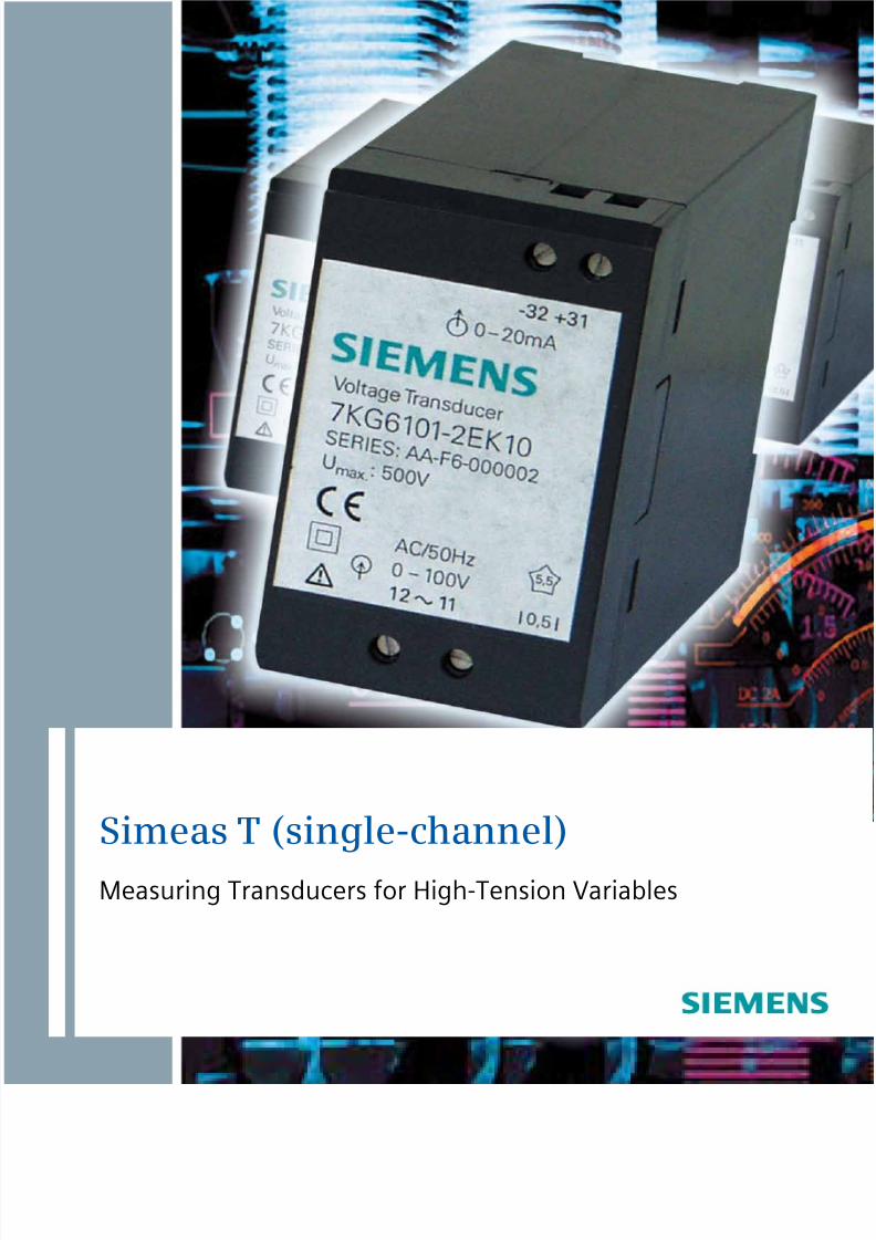
Simeas T (single-channel)
Measuring Transducers for High-Tension Variables
8/16/2019 Simeas t Product Overview
http://slidepdf.com/reader/full/simeas-t-product-overview 2/12
Small dimensions Fast delivery times, standardtypes from stock
CE-marking Resistant to EMV- interference
Compliant with the relevantnational and internationalstandards
High quality, long lifetime
Galvanic isolation with highbreakdown voltage
High measurement accuracy
Powerful output circuitry High equipment safety andreliability
Features
Characteristics
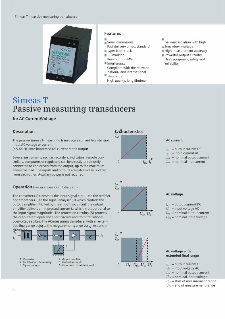
AC current
I A
I E
I AN
I EN
= output current DC= input current AC= nominal output current= nominal inpt current
I A
U E
I AN
U EN
= output current DC= input voltage AC= nominal output current= nominal input voltage
I A
U E
I AN
U EN
U E1
U E2
= output current DC= input voltage AC= nominal output current= nominal input voltage= start of measurement range= end of measurement range
AC voltage
AC voltage with
extended fnal range
4
Simeas T – passive measuring transducers
Simeas T
Passive measuring transducersfor AC Current/Voltage
Description
The passive Simeas T-measuring transducers convert high-tensioninput AC voltage or current(45-65 Hz) into impressed DC current at the output.
Several instruments such as recorders, indicators, remote con-trollers, computers or regulators can be directly or remotely
connected to and driven from the output, up to the maximumallowable load. The inputs and outputs are galvanically isolatedfrom each other. Auxiliary power is not required.
Operation (see overview circuit diagram)
The converter (1) transmits the input signal I E or U E via the rectierand smoother (2) to the signal analyser (3) which controls theoutput amplier (4). Fed by the smoothing circuit, the outputamplier delivers an impressed current I A, which is proportional tothe input signal magnitude. The protection circuitry (5) protectsthe output from open and short-circuits and from transitionalovervoltage spikes. The AC-measuring transducer with an exten-ded nal range adjusts the measurement range via an expansioncircuit (6).

8/16/2019 Simeas t Product Overview
http://slidepdf.com/reader/full/simeas-t-product-overview 3/12
Input
For connection to AC voltagesystems only
Maximum nominal supply voltage Y 230 / ∆ 400 V and ∆ 500 V
Power consumption 0,3 VA where I AN = 2,5 mA(per channel where I = I EN) 0,4 VA where I AN = 5 mA
0,6 VA where I AN= 10 mA
0,9 VA where I
AN = 20 mAPermissible output range 1,2 I EN or 1,2 U EN
Nominal frequency f EN 50 Hz; 60 HzFrequency range f E 45 Hz to 65 HzWaveform sine
Measuring transducer input ac-current I EStandard nominal current I EN See ordering data
Constant overload
where I EN = 1 A, 1,2 A 2 Awhere I EN = 1,5 A 3 Awhere I EN = 2 A, 2,4 A 4 Awhere I EN = 2,5 A 5 Awhere I EN = 5 A, 6 A 10 Awhere I EN = 7,5 A 12 A
where I
EN = 10 A 15 ASurge overload
where I EN = 1 A, 1,2 A, 1,5 A 50 A for 1 secwhere I EN = 2 A, 2,4 A, 2,5 A 100 A for 1 secwhere I EN = 5 A, 6 A, 7,5 A, 10 A 200 A for 1 sec
Measuring transducer input AC voltage U EN
Standard nominal voltage U EN see ordering data
Custom nominal voltage U EN range 40 to 500 V
Constant overload 1,5 x U EN but max 600 V
Surge overload ≤ 2 x U EN (5 pulses 1 sec, in5 secs apart)
Output
impressed DC current openand short circuit protected
Standard nominal current I AN 2,5 mA, 5 mA, 10 mA, 20 mA
Custom nominal current I AN range 1 to 20 mA
Nominal output range 0 to I AN
Permissible output range 0 to 1,2 I AN
Open-circuit voltage U AL ≤ 30 V
Nominal load RBIN 7,5 V / I AN
Operational load RB 0 to 15 V / I AN
Residual ripple I SS ≤ 0,5 % SS of I AN
Setting time t 99
Measuring transducer AC current ≤ 1 s Measuring transducer AC voltage ≤ 0,4 s
Errors and inuential effects
Relative errors with + or - sign
Errors under reference conditions 0,5 % relative to I AN
Reference conditions
Input current I E 0,05 IEN to I EN Input voltage U E 0,2 UEN to U EN Frenquency f E f EN ± 1 % Waveform sine, distortion factor ≤ 0,2 % Load RB RBIN ± 1 % Ambient temperature T U 23 °C ± 1 °CWarm-up time ≤ 15 min Extraneous elds none
Inuential effects of
input voltage from ≤ 0,4 % UEN to 1,2 U EN
input current from0 to 0,05 I EN ≤ 0,5 % IEN to 1,2 I EN ≤ 0,1 %
ambient temperature ≤ 0,3 % / 10 K
frequency (45 - 65 Hz) ≤ 0,03 % / Hz harmonic frequencies
(3rd harmonics only) ≤ 0,33 x distortion factor in %
load ≤ 0,2 % when load changesfrom 0 Ω to 15 V / I AN
warming-up ≤ 0,3 %
Other technical details
Surge voltage VDE 0435part 303 at type-testing
input versus output U = 5 kV, 1,2 / 50 µsec
input and output as R = 500 Ω 3 pulses in each differential voltage polarity direction
Dielectric strength (Test voltage)
input versus output U rms = 5,5 kV, 50 Hz sine,1 min (type-testing)
Permissible ambient temperatureaccording to IEC 68-2 / 1-3
working temperature range - 10 °C to + 60 °Cfunctional temperature range - 25 °C to + 70 °Cstorage temperature range - 40 °C to + 85 °C
Climatic application class EN 60721-3-3(seldom slight condensation)Environment class IR 2
Mechanical resistance
against dropping,vibration and shock to DIN EN 61010 part 1
Fire resistance class V0
Safety to DIN EN 61010 part 1
Safety measures
Overvoltage category III
Pollution category 2
Electromagnetic compatibility
Interference emission to DIN EN 50081-1
Radio interference eld strength to DIN EN 55022 class B
Interference immunity to EN 50082-2
Interference immunity toelectromagnetic elds 10 V / m to IEC 801-3
Static electricity discharge
ESD 8 kV to IEC 801-2Fast transients unsymmetricalburst 2 kV with cap. coupling to IEC 801-4
Dimensions
5
Simeas T – passive measuring transducers

8/16/2019 Simeas t Product Overview
http://slidepdf.com/reader/full/simeas-t-product-overview 4/12
Nominal frequency f EN
50 Hz 260 Hz 3
Input voltage U EN
40 V K100 / √3 V A60 V L110 / √3 V B120 / √3 V C132 / √3 V D100 V E110 V F120 V J
132 V N150 V P220 V G230 V W240 V V250 V Q300 V U380 V H400 V R500 V SOther input voltages according tothe details supplied in plain text Z
1) J1Y
Output signal I
ANDC 0 to 2,5 mA GDC 0 to 5 mA HDC 0 to 10 mA JDC 0 to 20 mA KOther output signal ranges ≥ 1mA DC(however not live-zero)according to the details supplied inplain text Z
1) K1Y
Nominal frequency f EN
50 Hz 260 Hz 3
Input voltage U EN
1 A A1,2 A B1,5 A K2 A C2,4 A D2,5 A L5 A E6 A F7,5 A G
10 A J
Output signal I AN
DC 0 to 2,5 mA GDC 0 to 5 mA HDC 0 to 10 mA JDC 0 to 20 mA KOther output signal ranges ≥ 1mA DC(however not live-zero)according to the details supplied inplain text Z
1) K1Y
7KG4000-8AAOperating instructions2) for
7KG6101 und 7KG6111
German, English, French, Spanish and Italian
Notice
Not all possible combinations
are available
1) Only after consulting with the suppliers2) One set of operating instructionsis supplied with each unit
Measuring transducer
for AC Voltage 7KG6101- 1 0
Measuring transducer
for AC Voltage 7KG6111- 1 0
Order-Nr. Order-Nr.
6
Simeas T – passive measuring transducers
Selection and Ordering Details

8/16/2019 Simeas t Product Overview
http://slidepdf.com/reader/full/simeas-t-product-overview 5/12
Small dimensions Fast delivery times,standard types from stock
CE-marking Resistent to EMV- interference
Compliant with the relevantnational and internationalstandards
High quality, long lifetime
Galvanic isolation with highbreakdown voltage
High measurement accuracy
Powerful output circuitry High equipment safety andreliability
Features
Simeas T
Active measuring transducers
for AC Current/Voltage (effective value)
Application area
The active Simeas T-measuring transducers with an auxiliarypower supply convert the effective value of high-tension inputAC voltage or current into impressed DC current or voltage at theoutput.
Several instruments such as recorders, indicators, remote con-trollers, computers or regulators can be directly or remotelyconnected to and driven from the output, up to the maximumallowable load. The input, output and auxiliary power supply aregalvanically dependent on each other.
Operation (see overview circuit diagram)
The converter (1) transfers the input signal I E or U E via the rectierand smoother (2) to the signal analyser (3), which controls theoutput amplier (4). Fed by the smoothing circuit, the output am-plier delivers an impressed current I A that is proportional to theinput value I E. The protection circuitry (5) protects the output froman open-circuit and from transitional overvoltage spikes.
The AC measuring transducers with an extended nal range orextended initial range or with a knee-characteristic all adjust theirmeasurement range via an expansion circuit (6).
The auxiliary AC or DC power is converted into an internal powersupply via an AC or a DC auxiliary power module (7).
Construction
The measuring transducers are hard-wired and tested functionalunits. A snap-tting is provided for a 35mm mounting rail to DINEN 50022.
The inputs, outputs and auxiliary power can be reliably connectedwith screw-terminals.
The units are free from silicon and halogens, and are of low-am-mability.
Adjustment potentiometer and test points are accessible after theremoval of the housing cover.
7
Simeas T – active measuring transducers

8/16/2019 Simeas t Product Overview
http://slidepdf.com/reader/full/simeas-t-product-overview 6/12
8
Simeas T – active measuring transducers
Input
For connection to AC voltagesystems only
Maximum nominal supply voltage Y 230 / ∆ 400 V and ∆ 500 V
Permissible output range 0 - 1,2 I EN or 1,2 U EN
Nominal frequency f EN 50 Hz; 60 Hz
Frequency rangef
E 45 Hz to 65 HzWaveform Sine, pulse, triangular orphase-angle
Peak factor i/ I rms or û/U rms ≤ 2
Measuring transducer input AC current I EN
Standard nominal current I EN See ordering data
Measurement range in I EN 0 to I EN
Constant overload 2 I EN
Surge overload
where I EN = 1 A 100 A for 1 secwhere I EN = 5 A 200 A for 1 sec
Measuring transducer input AC voltage U EN
Standard nominal voltage U EN see Selection and Ordering DetailsCustom nominal voltage U EN within range 40 to 500 V
Measurement range in nominalvalue U EN 0 to U EN
Constant overload 1,5 x U EN but max. 600 V
Surge overload ≤ 2 x U EN (5 pulses 1 s, 5 secs apart)
Output I Aimpressed DC current orimpressed DC voltageopen and short circuit protected
Standard nominal current I AN 2,5 mA, 5 mA, 10 mA, 20 mA
Custom nominal current I AN within range 1 to 20 mA
Nominal output range 0 to I AN or 4 - 20 mA
Permissible output range 0 to 1,2 I AN
Zero displacement range 0 o I AN
Open-circuit voltage U AL ≤ 30 V
Nominal load RBIN 7,5 V / I AN
Operational load RB 0 to 15 V / I AN
Standard nominal voltage U AN 1 V; 10 V
Nominal output range 0 to U AN
Permissible output range 0 to 1,2 U AN
Zero displacement within range 0 to U AN
Short-circuit current ≤ 25 mA
Nominal load RBUN U AN / 1 mA
Load current I B ≤ 5 mAResidual ripple I SS ≤ 0,5 % SS of I AN or U AN
Setting time t 99 ≤ 350 ms
Auxiliary Power U HInput voltage U HIN
DC voltage DC 24 - 60 V; 110 - 200 VAC voltage AC 100/115/230 V; 45 - 65 Hz
Input range ± 20 %
Power consumption whereU H = U AN , typical valueDC voltage 2,5 WAC voltage 2,5 W / 4 VA
Errors an inuential effects
Relative errors with+ or - sign
Error under reference conditions 0,3 % relative to I AN
Reference conditions
Input current I E 0 to I EN Input voltage U E 0 to U EN Frequency f E f EN ± 0,5 % Waveform sine, distortion factor ≤ 5 %Auxiliary AC voltage U H U HIN ± 1 %, distortion factor 5 %
frequency f EN ± 2 % Auxiliary DC voltage U H U HIN ± 1 %, ripple ± 2 % Load RB RBIN ± 1 %, U BUN ± 1 % Ambient temperature T u 23 °C ± 1 °CWarm-up time ≥ 15 min Extraneous elds none
Inuential effect of
ambient temperature ≤ 0,2 % / 10 K frequency (45 bis 65 Hz) ≤ 0,04 % / Hz waveform ≤ 0,02 % je 10 % distortion factor,
(peak factor ≤ 2) load with current outputfor RB = 15 V / I AN ≤ 0,1 % load with voltage outputfor RB = to I AN / 20 mA ≤ 10 mV auxiliary powerU H = 0,8 to 1,2 U HIN ≤ 0,1 %
warming-up ≤ 0,3 %
Other technical details
Basic standard 1EC 60688
Surge voltage VDE 0435 input versus outputpart 303 at type-testing input versus auxiliary power
output versus auxiliary poweras differential voltage
at input Û = 5 kV, 1,2 / 50 µsec, Ri = 500 Ω at output Û = 5 kV, 1,2 / 50 µsec, Ri = 500 Ω
3 pulses in each polaritydirection
Dielectic strength (Test voltage)
input versus output U off = 5,5 kV, 50 Hz, sine, 1 mininput versus auxiliary power U off = 5,5 kV, 50 Hz, sine, 1 min
output versus auxliary powerU
off = 3,7 kV, 50 Hz, sine, 1 minPermissible ambient temperature to IEC 68-2 / 1-3 (typ-testing)
working temperature range - 10 °C to + 60 °Cfunctional temperature range - 25 °C to + 70 °Cstorage temperature range - 40 °C to + 85 °C
Climatic application class EN 60721-3-3temperature 3K8H, humidity 3K5 (seldom slight condensation)
Mechanical resistance to DIN EN 61010 part 1
against dropping,vibration and shock
Fire resistance class V0
Safety to DIN EN 61010 part 1
Overvoltage category III
Pollution grade 2
Electromagnetic compatibility
Interference emission to DIN EN 50081-1
Radio interference eld strength to DIN EN 55022 class B
Network feedback effect to DIN EN 55011 class B
Interference immunity to EN 50082-2
Interference immunity toelectromagnetic elds 40 V / m to IEC 801-3
Static electricity dischargeESD 8 kV to IEC 801-2
Fast transients, unsymmetricalburst 2 kV with cap. coupling to IEC 801-4
Surge to IEC 801-5 HF Power supply to IEC 801-6

8/16/2019 Simeas t Product Overview
http://slidepdf.com/reader/full/simeas-t-product-overview 7/12
Order-Nr. Order-Nr.
9
Simeas T – active measuring transducers
Selection and Ordering Details
Measuring transducer
for AC Voltage 7KG6106- - B
Nominal frequency f EN
50 Hz 260 Hz 3Other nominal frequency1) 9 H1Y
Input current AC 40 V K100 / √3 V A60 V L110 / √3 V B120 / √3 V C132 / √3 V D100 V E110 V F
120 V J132 V N150 V P220 V G230 V W240 V V250 V Q300 V U380 V H400 V R500 V SOther input voltagesup to max. 500 V1) Z2) J1Y
Output signalDC 0 bis 2,5 mA GDC 0 bis 5 mA HDC 0 bis 10 mA JDC 0 bis 20 mA K(Live zero) DC 4 bis 20 mA N 2DC 0 bis 1 V LDC 0 bis 10 V MOther output ranges ≥ 1mA 1) Z2) K1Y
Zero positionMeasurement zone zero =signal zone zero 1Measurement zone zero at any positionin the signal zone1) 92) L2Y
Auxiliary powerDC 19,2 - 72 V 1DC 88 - 264 V 4AC 45 bis 65 Hz, 100 V 5AC 45 bis 65 Hz, 115 V 6AC 45 bis 65 Hz, 230 V 7
Measuring transducer
for AC Voltage 7KG6106- - B
Measurement range
Measurement range linear 0 to U EN 0
Extended initial range 0 to 0,05 U EN @ 0 to 0,8 I An 1 0 to 0,1 U EN @ 0 to 0,8 I An 2
Extended nal range 0 to 0,9 to 1,1 U EN @ 0 to 0,2 I An 3 0 to 0,85 to 1,15 U EN @ 0 to 0,2 I An 4 0 to 0,8 to 1,2 U EN @ 0 to 0,2 I An 5
Suppressed initial range 0 to 0,9 to 1,1 U EN @ 0 bis 0 I An 6
0 to 0,85 to 1,15U
EN @
0 bis 0 I
An 7 0 to 0,8 to 1,2 U EN @ 0 bis 0 I An 8
Other measurement ranges 92) M2Y
Operating instruction3) 7KG4000-8BA
for 7KG6106 und 7KG6113
German, English, French,Spanish and Italian
Dimensions
1) Order with ashort description in plain text.2) Only after consultation with suppliers3) One set of operating instructions is supplied with each unit
Continued
Notice
Not all possible combinations areavailable

8/16/2019 Simeas t Product Overview
http://slidepdf.com/reader/full/simeas-t-product-overview 8/12
Simeas T Active measuringtransducers
Preferred models in adouble-packfor AC Current/Voltage
Technical Data and Dimensions
Output signal 4 to 20 mA
Nominal frequency 50 to 60 Hz
Setting time t gg from 10 % of U / I EN 500 ms
Error under reference conditions ≤ 0,5 %
Input voltage AC100 V E110 V F120 V J
Auxiliary powerDC 100 - 125 V 3AC 230 V 7
Measuring transducer
for AC Voltage 7KG6104- 1 N 2
Input current AC1 A A5 A B Auxiliary powerDC 100 - 125 V 3AC 230 V 7
Measuring transducer
for AC current 7KG6114- 1 N 2
Order no.
10
Selection and Ordering Data
Measurement transducer
for AC current 7KG6113- - B
Nominal frequency f EN
50 Hz 260 Hz 3Other nominal frequency1) 9 H1Y
Input current AC1 A A1,2 A B1,5 A K2 A C2,4 A D2,5 A L5 A E6 A F
7,5 A G10 A JOther input current1) Z2) J1Y
Output signalDC 0 to 2,5 mA GDC 0 to 5 mA HDC 0 to 10 mA JDC 0 to 20 mA K(Live zero) DC 4 to 20 mA N 2DC 0 to 1 V LDC 0 to 10 V MOther output signal ranges1) Z2) K1Y
Zero positionMeasurement zone zero =signal zone zero 1Measurement zone zero at any positionin the signal zone1) 92) L2Y
Auxiliary powerDC 19,2 - 72 V 1DC 88 - 264 V 4AC 45 to 65 Hz, 100 V 5AC 45 to 65 Hz, 115 V 6AC 45 to 65 Hz, 230 V 7
Measurement rangeMeasurement range linear 0 to U EN 0Extended start-zone 0 to I E1 to I E2 @ A0 to A1 to A2 1) 92) N1YExtended end-zone 0 to I E1 to I E2 @ A0 to A1 to A2 1) 92) N2Y
Simeas T – active measuring transducers
Operating instructions3) 7KG4000-8BA
for 7KG6106 und 7KG6113
German, English, French, Spanish and Italian
1) Order with a short description in plain text2) Only after consultation with suppliers3) One set of operating instructions is supplied with each unit
Selection and Ordering Data
Order-Nr.
Order no.

8/16/2019 Simeas t Product Overview
http://slidepdf.com/reader/full/simeas-t-product-overview 9/12
Small dimensions Fast delivery times,standard types from stock
CE-marking Resistent to EMV- interference
Compliant with the relevantnational and internationalstandards
High quality, long lifetime
Galvanic isolation with highbreakdown voltage
High measurement accuracy
Powerful output circuitry High equipment safety andreliability
Features
Simeas T
DC measuring transducers Isolating amplifersfor DC current or AC voltage
Description
Simeas T-measuring transducers for DC voltage or DC current withauxiliary power convert the input DC voltage or DC current intoimpressed DC current or impressed DC voltage at the output.
Several instruments such as recorders, indicators, remote con-
trollers, computers, or regulators can be directly or remotelyconnected to and driven from the output, up to the maximumpermissible load. The input, output, and auxiliary power supplyare galvanically isolated from each other.
Operation
The input signal is calibrated via resistors (1) to the voltageratio converter (2). The pulse-wave signal from the voltage ratioconverter is ltered and transferred to the output side via thetransducer (3), and conditioned by the amplier (4). Accordingto the characteristic curve, the output amplier (5) delivers animpressed DC current I A or impressed DC voltage U A, which is pro-portional to the input value. The reference current I can be usedto displace the zero of the characteristic curve.
The auxiliary power isolator (6) produces the galvanically isolatedsupply voltage for the input circuitry.
The auxiliary power is converted into an internal voltage supplyvia an AC or a DC voltage module (8).
Construction
The measuring transducers are hard-wired and tested functionalunits. A snap-tting is provided for a 35mm mounting rail to DINEN 50022.
The inputs, outputs, and external power can be reliably connectedwith screw-terminals.
The units are free from silicon and halogens and are of low-am-mability.
Adjustment potentiometer and test points are accessible after theremoval of the housing cover.
11
Simeas T – DC measuring transducers/isolating ampliers

8/16/2019 Simeas t Product Overview
http://slidepdf.com/reader/full/simeas-t-product-overview 10/12
Inuential effects of
ambient temperature ≤ 0,2 % / 10 K
load with current outputfor RA = 15 V / I AN ≤ 0,1 %
load with voltage outputfor RA = bis I AN / 20 mA ≤ 10 mV
auxiliary power
U H = 0,8 bis 1,2 U HN ≤ 0,1 %warming-up ≤ 0,3 %
Other technical details
Impulse voltage VDE 0435part 303 at type-testing
imput versus output U = 5 kV, 1,2 / 50 µs, R=500Ω input versus auxiliary power U = 5 kV, 1,2 / 50 µs, R=500Ω output versus auxiliary power U = 5 kV, 1,2 / 50 µs, R=500Ω at input versus auxiliary power U = 5 kV, 1,2 / 50 µs, R=500Ω as differential voltage U = 5 kV, 1,2 / 50 µs, R=500Ω at output as differential U = 500 V, 1,2 / 50 µs, R=500Ω voltage 3 pulses in each polarity direction
Dielectric strength (Test voltage) at type-testingInput versus output U off = 5,5 kV, 50 Hz, sine, 1 min
Input versus auxiliary powerU
off = 5,5 kV, 50 Hz, sine, 1 minOutput versus auxiliary power U off = 3,7 kV, 50 Hz, sine, 1 min
Permissible ambient temperatureto IEC 68-2 / 1-3
working temperature range -10 °C to + 60 °Cfunctional temperature range -25 °C to + 70 °Cstorage temperature range -40 °C to + 85 °C
Climatic application class Temperature 3K8H EN 60721-3-3 Humidity 3K5
(seldom slight condensation)
Mechanical resistance
against droppingvibration and shock to DIN EN 61010 part 1
Safety
Safety measures to DIN EN 61010 part 1Overvoltage category to DIN EN 61010 part 1
where U EN = 0 - 500V IIIwhere U EN = 500 - 1000V II
Fire resistance class V0
Pollution grade 2
Electromagnetic compatibility
Interference emission to DIN EN 50081-1
Radio interference eld to DIN EN 55022 Kl. B resistance to EN 50082-2
Interference immunity toelectromagneticelds 10 V / m to EN 61000-4-3 (IEC 801-3)
static electricity dischargeESD 8 kV to EN 61000-4-2 (IEC 801-2) Fast transients, unsymmetrical burstinput and output 2 kV to EN 61000-4-4 (IEC 801-4)power supply 4kV
Surge to IEC 801-5HF Power supply 10 U off to IEC 801-6
Dimensions
12
Input
For connection only to DC voltage systems with a maximum nominalvoltage of 500 / 1000 V, see safety
Input signal E DC voltage U E orDC current I E
Standard nominal current I EN 1 mA, 2,5 mA, 5 mA, 10 mA,20 mA
Custom nominal current I EN value within range 1 mA
to 100 mANominal output range - I EN to 0 to + I EN
Permissible output range -1,2 I EN or +1,2 I EN
Voltage-drop at input at I EN 500 mV ± 5 %
Standard nominal voltage U EN 60 mV, 150 mV, 300 mV, 1 V,10 V, 15 V, 25 V, 30 V, 60 V, 100 V,150 V, 250 V, 300 V, 400 V, 500 V,600 V, 800 V, 1000 V
Custom nominal voltage U EN value within range 60 mVto 1000 V
Nominal output range -U EN to 0 to +U EN
Permissible output range -1,2 U EN to 0 to +1,2 U EN but max. 1000 V
input impedance RE
U EN = 60 mV bto 1 V RE 30 kΩ/V U EN = 1 V to 100 V RE 10 kΩ/V U EN = 100 V to 1000 V RE 2 kΩ/V
Output signal A
Bipolar impressed DC current or impressed DC voltageOpen and short circuit and protected
Standard nominal current I AN 1 mA, 2,5 mA, 5 mA, 10 mA, 20mA
Custom nominal current I AN value within range ± 1 to ± 20 mA
Nominal output range - I AN to 0 to + I AN or 4-20 mA
Permissible output range -1,2 I AN to 0 to +1,2 I AN
Zero displacement range - I AN to I AN
Open-circuit voltage U AL ≤ 30 V
Nominal load RBIN 7,5 V / I AN
Optional load RB 0 to 15 V / I AN
Standard nominal voltage U AN 1 V, 10 V
Nominal output range 0 to U AN
Permissible output range -1,2 U AN to 0 to +1,2 U AN
Zero displacement range 0 to U AN
Short-circuit current ≤ 25 mA
Residual ripple I SS ≤ 0,5 % SS of I AN or. U AN
Setting time t 99 ≤ 50 ms (residual error -1 %of nal value)
Auxiliary Power U HNominal input voltage U HN
DC voltage DC 24 - 60 V; 110 - 220 V
AC voltage AC 100/115/230 V; 45 - 65 HzInput range ± 20 %
Power consumption whereU H = U HN, typical avlueDC voltage 2 WAC voltage 1,6 W / 2,5 VA
Errors and inuential effects
Relative errors with + or - sign
Error under reference conditions 0,2 % relative to I AN
Reference conditionsInput current I E 0 to I EN Input voltage U EN 0 to U EN Auxiliary AC voltage U H U HN ± 1 %, distortion factor ≤ 5% Auxiliary AC voltage U H U HN ± 1 %, ripple ± 5% Load RB RBIN ± 1 %, RBUN ± 1 % Ambient temperature T U 23 °C ± 1 °CWarm-up time ≥ 15 min Extraneous elds none
Simeas T – DC measuring transducers/isolating ampliers

8/16/2019 Simeas t Product Overview
http://slidepdf.com/reader/full/simeas-t-product-overview 11/12
13
Simeas T – DC measuring transducers/isolating ampliers
Selection and Ordering Details
DC Voltage, DC Current
Isolating Amplifer 7KG6131- 1
DC input voltage E N
- 60 mV to 60 mV A- 150 mV to 150 mV B- 300 mV to 300 mV C- 1 V to 1 V L- 10 V to 10 V M- 15 V to 15 V D- 25 V to 25 V F- 30 V to 300 V X- 60 V to 60 V O- 100 V to 100 V Y- 150 V to 150 V P- 250 V to 250 V Q- 300 V to 300 V U
- 400 V to 400 V R- 500 V to 500 V S- 600 V to 600 V T- 800 V to 800 V V- 1000 V to 1000 V W
DC input current- 1 mA to 1 mA E- 2,5 mA to 2,5 mA G- 5 mA to 5 mA H- 10 mA to 10 mA J- 20 mA to 20 mA K
4 mA to 20 mA N
Other input signal according todetails supplied in plain text Z1) J1Y
DC output signal- 1 mA to 1 mA E- 2,5 mA to 2,5 mA G- 5 mA to 5 mA H- 10 mA to 10 mA J- 20 mA to 20 mA K- 1 V to 1 V L- 10 V to 10 V M
4 mA to 20 mA NOther output signal according todetails supplied in plain text Z1) K1Y
Zero positionInput Output
0 mA, V = 0 mA, V 10 mA, V = 4 mA 20 mA, V = 12 mA 3
4 mA = 0 mA, V 412 mA = 0 mA, V 5
any position, according to details supplied inplain text 91) L2Y
DC Voltage, DC Current
Isolating Amplifer 7KG6131- 1
Auxiliary power
DC 24 V to 60 V 1 DC 110 V to 220 V 4 AC 100 V 45 to 65 Hz 5 AC 115 V 45 to 65 Hz 6 AC 220 V 45 to 65 Hz 7
7KG4000-8BAOperating instructions2)
German, English, French,
Spanisch and Italian
Notice
Not all possible combinations
are available
1) Only after consultation with suppliers2) One set of operating instuctions is supllied with each unit
Order no. Order-no.

8/16/2019 Simeas t Product Overview
http://slidepdf.com/reader/full/simeas-t-product-overview 12/12
Siemens Aktiengesellschaft© Siemens AG 2007 - 2015
All Rights Reserved
Printed in GermanyÄnderungen vorbehalten
www.siemens.com/simeas-t