Embed Size (px)
Citation preview

Applikationen & Tools
Answers for industry.
Cover
Configurating of Cascade Control SIMATIC PCS 7
Application May 2010

2 Configuring a Cascade Control
V 1.0, Entrys-ID: Entry ID
Co
pyr
igh
t
Sie
me
ns
AG
20
10
All
righ
ts r
ese
rve
d
Industry Automation and Drives Technologies Service & Support Portal
This article is taken from the Service Portal of Siemens AG, Industry Automation and Drives Technologies. The following link takes you directly to the download page of this document.
http://support.automation.siemens.com/WW/view/en/43033319
If you have any questions concerning this document please e-mail us to the following address:

Configuring a Cascade Control V 1.0, Entry-ID: Entry ID 3
Co
pyr
igh
t
Sie
me
ns
AG
20
10
All
righ
ts r
ese
rve
d
43
033
319
_C
asc
ade
Ctr
l_E
N.d
oc
Preface
Objective of the Application
A cascade control structure can be established if, beside the main process variable, more system variables are measured and fed back as auxiliary process variables, creating subordinate control loops. Thus there is a master (or main) control loop and a slave (or auxiliary) control loop.
Cascade control is one of the most common control system structures in process plants.
The project example shows the application of cascade control to a simulated process with one main and one auxiliary process variable. The objective of this application note is to show the issues in configuration of cascade control loops that are particularly relevant to achieve fast dynamics and correct behaviour in all operating modes of real world applications.
Main Contents of this Application Note
The following issues are discussed in this application note:
Interaction between master and slave controller with respect to controller tuning
Interaction between master and slave controller with respect to operating mode changeovers
Simulation example
Validity
… valid for PCS 7 V7.1, in principal transferable to V7.0 SP1.


Configuring a Cascade Control V 1.0, Entry-ID: Entry ID 5
Co
pyr
igh
t
Sie
me
ns
AG
20
10
All
righ
ts r
ese
rve
d
s
SIMATIC PCS 7 Cascade Control
Indroduction
1 Configuration of Cascade Control
2
Simulation Example
3
Conclusion
4
Related Literature
5
History
6

Warranty and Liability
6 Configuring a Cascade Control
V 1.0, Entrys-ID: Entry ID
Co
pyr
igh
t
Sie
me
ns
AG
20
10
All
righ
ts r
ese
rve
d
Warranty and Liability
Note The Application Examples are not binding and do not claim to be complete regarding the circuits shown, equipping and any eventuality. The Application Examples do not represent customer-specific solutions. They are only intended to provide support for typical applications. You are responsible for ensuring that the described products are used correctly. These application examples do not relieve you of the responsibility to use safe practices in application, installation, operation and maintenance. When using these Application Examples, you recognize that we cannot be made liable for any damage/claims beyond the liability clause described. We reserve the right to make changes to these Application Examples at any time without prior notice. If there are any deviations between the recommendations provided in these application examples and other Siemens publications – e.g. Catalogs – the contents of the other documents have priority.
We do not accept any liability for the information contained in this document.
Any claims against us – based on whatever legal reason – resulting from the use of the examples, information, programs, engineering and performance data etc., described in this Application Example shall be excluded. Such an exclusion shall not apply in the case of mandatory liability, e.g. under the German Product Liability Act (“Produkthaftungsgesetz”), in case of intent, gross negligence, or injury of life, body or health, guarantee for the quality of a product, fraudulent concealment of a deficiency or breach of a condition which goes to the root of the contract (“wesentliche Vertragspflichten”). The damages for a breach of a substantial contractual obligation are, however, limited to the foreseeable damage, typical for the type of contract, except in the event of intent or gross negligence or injury to life, body or health. The above provisions do not imply a change of the burden of proof to your detriment.
Any form of duplication or distribution of these Application Examples or excerpts hereof is prohibited without the expressed consent of Siemens Industry Sector.

Table of Contents
Configuring a Cascade Control V 1.0, Entry-ID: Entry ID 7
Co
pyr
igh
t
Sie
me
ns
AG
20
10
All
righ
ts r
ese
rve
d
Table of Contents Preface .......................................................................................................................... 3 Warranty and Liability ................................................................................................. 6 1 Indroduction....................................................................................................... 8
1.1 Basic Principles of Cascade Control .................................................... 8 1.2 What to Consider for any Cascade Control Loop? .............................. 9 1.3 Priorities of Different Operating Modes ................................................ 9 1.4 Application Examples......................................................................... 10
2 Configuration of Cascade Control ................................................................. 13 2.1 Configuration: Creating an Instance of the Process Tag Type .......... 13 2.2 Manual Connection of Master and Slave Controller .......................... 14 2.3 Controller Design and Commissioning............................................... 17 2.3.1 Controller Structures: PID → PI and PI → P Cascade ...................... 17 2.3.2 PID-Tuner........................................................................................... 17 2.4 Combined Structures.......................................................................... 18
3 Simulation Example......................................................................................... 20 4 Conclusion ....................................................................................................... 25 5 Related Literature ............................................................................................ 26 6 History............................................................................................................... 27

1 Indroduction
8 Configuring a Cascade Control
V 1.0, Entrys-ID: Entry ID
Co
pyr
igh
t
Sie
me
ns
AG
20
10
All
righ
ts r
ese
rve
d
1 Indroduction
1.1 Basic Principles of Cascade Control
A cascade control structure involves two or more PID controllers in serial connection. The manipulated variable of the master controller is connected to the external setpoint of the slave controller so that both control loops are nested.
Figure 1-1: Cascade control structure
PID
Sla ve
controller
Setp oint
Outputdistu rban ce
PID
M aster
co ntrolle r Ma in pro cess
Inputdistu rbance
Control led
variab leAuxil iary proce ss
v _e
w
v _a
The advantage of cascade control is that disturbances affecting the inner loop can be compensated much more quickly in the slave loop than in the slower master loop.
In some situations, non-linear effects of the actuator (e.g. valve) can be compensated in the slave loop so that a linear process response can be achieved for the main control loop.
Cascade control is only feasible when there are further measurable variables in the process in addition to the main control variable and when the inner control loop is significantly faster than the outer loop.
The inner controller will be chosen such that the dynamics of the inner control loop is beneficial, e.g. time constants of the inner loop are compensated. If there is a disturbance affecting the inner loop of the system, this can be controlled better than with single-loop control, where disturbances possibly have to pass through the slow time constants of the outer loop.
In Chapter 3 you can see which advantages a cascade control structure has compared to single-loop control of the same system, particularly with respect to disturbance compensation.

1 Indroduction
Configuring a Cascade Control V 1.0, Entry-ID: Entry ID 9
Co
pyr
igh
t
Sie
me
ns
AG
20
10
All
righ
ts r
ese
rve
d
1.2 What to Consider for any Cascade Control Loop?
The following notes from [2.], page 7-9 are relevant for all kinds of cascade control.
The manipulated variable range of the master controller must match the setpoint range of the slave controller to ensure proper operation of the anti-windup functions of the master controller. By design of actuators (valves, pumps) and specification of set point-range of slave controller it has to be ensured that the slave controller does not work near the edge of its setpoint range at the typical operating point of the master controller, because otherwise the slave controller will have less power of intervention into the process.
If the slave controller is not operated in "cascade" mode (automatic mode with external setpoint) but in any other mode (for example manual or automatic mode with local setpoint) and therefore does not respond to commands of the master controller, the master controller must be switched into "tracking" mode to prevent wind-up of the integral action in the master controller. The manipulated variable of the master controller tracks the process value or setpoint of the slave controller to allow a bumpless return to cascade mode. The difference between tracking the setpoint and tracking the process value becomes apparent when the slave controller is put into manual mode. If the process value is tracked, the response is similar to "Track setpoint to process value in manual mode" of a single loop controller.
If the slave controller reaches a (high/low) manipulated variable limit, the integrator of the master controller must be blocked to prevent it from going on any further in this direction (up / down). The slave controller cannot go any further in this direction anyway. This prevents windup of the master controller when the real actuator has already reached its physical limits while the master controller has not yet reached its manipulated variable limits.
CAUTION The direction of blocking the integrator of the master controller has to be reversed if the slave controller has a negative gain. I.e. if the slave controller reaches a high limit, the integrator of the master controller must be prevented from going further down and vice versa.
1.3 Priorities of Different Operating Modes
The operating mode “manual” of the master controller has higher priority than tracking caused by the slave controller. The operating mode “manual” again has lower priority than force-mode caused by an external logic, e.g. emergency shutdown of the plant (controller input MV_Forced, not limited, activated by MV_ForOn with highest priority). Hence there is an additional tracking input MV_Trk at the PIDConL block of the Advanced Process Library, activated by input MV_TrkOn. This value is limited by the manipulated variable limits and has lower priority than the operating mode “manual”.

1 Indroduction
10 Configuring a Cascade Control
V 1.0, Entrys-ID: Entry ID
Co
pyr
igh
t
Sie
me
ns
AG
20
10
All
righ
ts r
ese
rve
d
Note If you work with a PID-controller from the „classic“ PCS 7 Library V7.1 or former PCS 7-versions e.g. with the CTRL_PID-Block, the second tracking input is not existing. In these controllers the tracking mode with the input LMN_TRK, activated by LMN_SEL has higher priority than the operating mode “manual”. As long as you are running the master controller of a cascade structure in that tracking mode, the operator at the OS has no chance to operate this controller manually.
1.4 Application Examples
Temperature control of a reactor or tank via flow of a heating medium (or cooling medium): TICreactor → FICheat medium → Valve heat medium See Figure 1-2.
Temperature control of the inner reactor temperature via slave controller for the jacket temperature, sometimes with subordinated controller for heating- and cooling medium flow (multi cascade!): TICreactor → TICjacket → FICheat medium → Valve heat medium
Often in combination with split-range at the slave controller because of heating and cooling. See Figure 1-2.
Temperature control of a furnace via slave controller for fuel flow (or combustion gas pressure): TICoven → FICfuel → Valve fuel.
Level control of a tank via slave controller for feed- and/or drain flow: LICtank → FICdrain → Valve drain
Temperature control of a distillation column (master controller) via reflux ratio (slave controller at column head) or vapor flow (slave controller column bottom).
Position control (drive technology) as a multi cascade structure with slave controllers for revolution speed and torque.
Note Generally slave controllers for flow are applied to avoid that control objectives of the master controller are disturbed by flow fluctuations. Furthermore, typical nonlinearities of the flow actuator (e.g. the valve) are “hidden“ in the slave control loop, because the closed slave control loop shows a linear behaviour. This way, nonlinearities of the valve have no effects on the master control loop and its controller design.

1 Indroduction
Configuring a Cascade Control V 1.0, Entry-ID: Entry ID 11
Co
pyr
igh
t
Sie
me
ns
AG
20
10
All
righ
ts r
ese
rve
d
Figure 1-2: Temperature control of a reactor via flow of heating medium by heat exchanger, Source: [3.]
TRC
345FRC
456
Figure 1-3: Temperature control of a furnace via slave controller for combustion gas pressure, Source: [2.]
feed
combustion gas
product
exhaust gas

1 Indroduction
12 Configuring a Cascade Control
V 1.0, Entrys-ID: Entry ID
Co
pyr
igh
t
Sie
me
ns
AG
20
10
All
righ
ts r
ese
rve
d
Figure 1-4: Temperature control of the inner reactor temperature via slave controller for the jacket temperature, with split-range-function for heating-and cooling valve, Source: [4.]

2 Configuration of Cascade Control
Configuring a Cascade Control V 1.0, Entry-ID: Entry ID 13
Co
pyr
igh
t
Sie
me
ns
AG
20
10
All
righ
ts r
ese
rve
d
2 Configuration of Cascade Control If you implement a new cascade control structure in your project, it is recommended to make use of the process tag type "CascadeControl" from the Advanced Process Library.
2.1 Configuration: Creating an Instance of the Process Tag Type
The following steps are carried out for the cascade control in the same way as for any other process tag type.
Open the Advanced Process Library with SIMATIC-Manager: Open project/Library/PCS 7 AP Library V71.
Figure 2-1: Open the “PCS 7 AP Library V71“
Copy the process tag type “CascadeControl” from the subfolder “Templates” into the master data library of your PCS 7 multiproject and modify it if necessary according to your general application requirements.

2 Configuration of Cascade Control
14 Configuring a Cascade Control
V 1.0, Entrys-ID: Entry ID
Co
pyr
igh
t
Sie
me
ns
AG
20
10
All
righ
ts r
ese
rve
d
Figure 2-2: Selection of process tag type
Copy the process tag type from the master data library to the application part <project name>_Prj of your multiproject, in the appropriate target folder (Process cell/Unit etc.) in the plant view. You obtain an instance of the process tag type i.e. a CFC chart, which indicates its origin by its symbolic representation.
Rename the new CFC chart and check if the cyclic interrupt OB is correct (in the CFC chart “Edit”/”Open run sequence”).
2.2 Manual Connection of Master and Slave Controller
A manual connection is only required if you want to establish cascade structures in existing control loops in the PLC and therefore you are not prepared to apply the predefined process tag types.
Realize the following connections:
Connect the output variable MV of the master controller to the input variable SP_Ext of the slave controller.
Connect the output variable MV of the slave controller to the analog output driver block for the actuator.
Provide the two controllers with the particular process variables, ranges of values and units from the analog input drivers
The manipulated variable range of the master controller must match the setpoint range (SP_ExtHiLim…SP_ExtLoLim) of the slave controller so that the anti-windup function of the master controller works properly. Therefore the manual MV limits of the master controller are connected to the setpoint limits of slave controller (green mark [1]). In many cases the “automatic limits” of the master controller are also connected to the same values.
If the slave controller reaches a limit of its manipulated variable, the integrator of the master controller is blocked (blue Mark [2]).
If the master controller is not in the operating mode “cascade” (automatic mode with external setpoint) but in any other operating mode (e.g. manual or automatic mode with local setpoint) and therefore not ready for commands by the master controller (shown by PID.CascaCut= true), the master controller must be taken into “tracking mode”. An OR-block will be placed in front of the binary input variable PID.MVTrkOn, because the tracking mode has to be activated as well if there is a

2 Configuration of Cascade Control
Configuring a Cascade Control V 1.0, Entry-ID: Entry ID 15
Co
pyr
igh
t
Sie
me
ns
AG
20
10
All
righ
ts r
ese
rve
d
sensor fault. To assure bumpless transfer back to cascade mode the manipulated variable of the master controller PID.MVTrk must be tracking PV_Slave.PV_Out.
The cycle time of the slave controllers in cascades must be at least as fast as the cycle time of the master controller.

2 Configuration of Cascade Control
16 Configuring a Cascade Control
V 1.0, Entrys-ID: Entry ID
Co
pyr
igh
t
Sie
me
ns
AG
20
10
All
righ
ts r
ese
rve
d
Figure 2-3: Connections between master and slave controller
[1]
[1]
[2]
[2]
[1][1]
[1]
[2][2]
[2][2]

2 Configuration of Cascade Control
Configuring a Cascade Control V 1.0, Entry-ID: Entry ID 17
Co
pyr
igh
t
Sie
me
ns
AG
20
10
All
righ
ts r
ese
rve
d
2.3 Controller Design and Commissioning
The controller design and start of operation are performed "from inside to outside", i.e. first the slave controller is designed and taken in automatic mode. Then the slave controller is switched into cascade mode and the master controller is designed.
Please note that the closed inner control loop appears as the controlled system for the master controller. Therefore the design of master controller depends on the parameter setting of the slave controller. The bigger the difference in dynamics of auxiliary and main control loop, the less attention is needed with respect to this interaction.
2.3.1 Controller Structures: PID → PI and PI → P Cascade
It is generally recommended that the slave controller of cascade structures is “simpler” than the master controller, i.e. that it has less different dynamic channels (proportional, integral and differential part), because the slave controller then “subordinates” itself to the master controller more easily.
PI → P Cascade
A steady-state deviation of the slave controller is normally not relevant for the application. In contrast the response time of the slave control loop is important, because the time constants of the closed slave loop are a part of the controlled system for the master controller. Therefore the structure PI→P cascade with a proportional-only slave controller is particularly recommended.
If (for these reasons) the slave controller is working without integral action, it is not recommended to specify the setpoint limits of the slave controller exactly to the physical range of the controlled variable of the slave controller, because in this case the operating range of the slave controller is not fully exploited due to the steady-state control error. Instead of that the setpoint limits of the slave controller and the corresponding MV limits of the master controller are adjusted generous.
In this case the anti-windup functions of the master controller are depending on the connections of IntHoldNeg and IntHoldPos. If the slave controller has no integral action, it also has no bumpless manual-automatic switching. Therefore an MV_Offset should be specified approximating the typical MV value for the operating point of the process.
In [1.], Figure 3-2and Figure 3-3 it is shown that the dynamic performance of a PI→P cascade is better than PI→PI cascade if the time constants of inner and outer controlled system are in the same order of magnitude.
PID → PI Cascade
The slave controller subordinates itself to the master controller also in a constellation with a PID master and PI slave controller. The slave controller now has an integral action and therefore no more steady-state control error. The master controller achieves a faster compensation of disturbances with the help of his differential action. However, these advantages are bought by higher actuator activity. If a valve is used as an actuator the issues of wear and tear, and the consumption of compressed air (energy) have to be considered. The differential action therefore is rarely applied in combination with valves as actuators.
2.3.2 PID-Tuner
The PID-Tuner can be used for cascade control as usual, by calculating the parameters of the slave controller first. Afterwards the slave controller is taken into automatic mode with external setpoint and the parameters found by the tuner. In

2 Configuration of Cascade Control
18 Configuring a Cascade Control
V 1.0, Entrys-ID: Entry ID
Co
pyr
igh
t
Sie
me
ns
AG
20
10
All
righ
ts r
ese
rve
d
the next step you determine the controller parameters of the master controller by application of the PID tuner
2.4 Combined Structures
Cascade structures are often applied in combination with other control structures. The combination of cascade and split-range control is already mentioned in chapter 1.4. The combination with feedforward disturbance control or gain scheduling is also possible in a straighforward way. Cascade structures with a model based predictive controller as master controller and several PID slave controllers are popular and described in the application note “Multivariable Model Predictive Control – the Distillation Column as an Application Example”.
In case of multi cascade structures each slave controller is connected to its directly superior master controller as described in chapter 2.2. Therefore an operating mode switch will have effects from inner to outer loops: If the innermost controller is taken out of cascade mode, it will inform its master controller which then goes into tracking mode, i.e. the master controller also leaves the cascade mode and also informs its master controller and so on.
Figure 2-4: Ratio control, FIC2.SP= FIC1.SP * Ratio, source: [5.]
If several fluids or gasses are to be mixed in a specified ratio, this can be realized with a ratio control structure (Figure 2-4) consisting of several flow controllers and a ratio function block. Ratio control shows structural similarities to cascade control. The (external) set point of the flow controller FIC2 of the mixed component is derived from the set point or process variable of the master controller FIC1, in a defined ratio. If the slave controller leaves the cascade mode, corresponding tracking functions must be activated, in this case at the ratio block.
2 Configuration of Cascade Control
Configuring a Cascade Control V 1.0, Entry-ID: Entry ID 19
Co
pyr
igh
t
Sie
me
ns
AG
20
10
All
righ
ts r
ese
rve
d
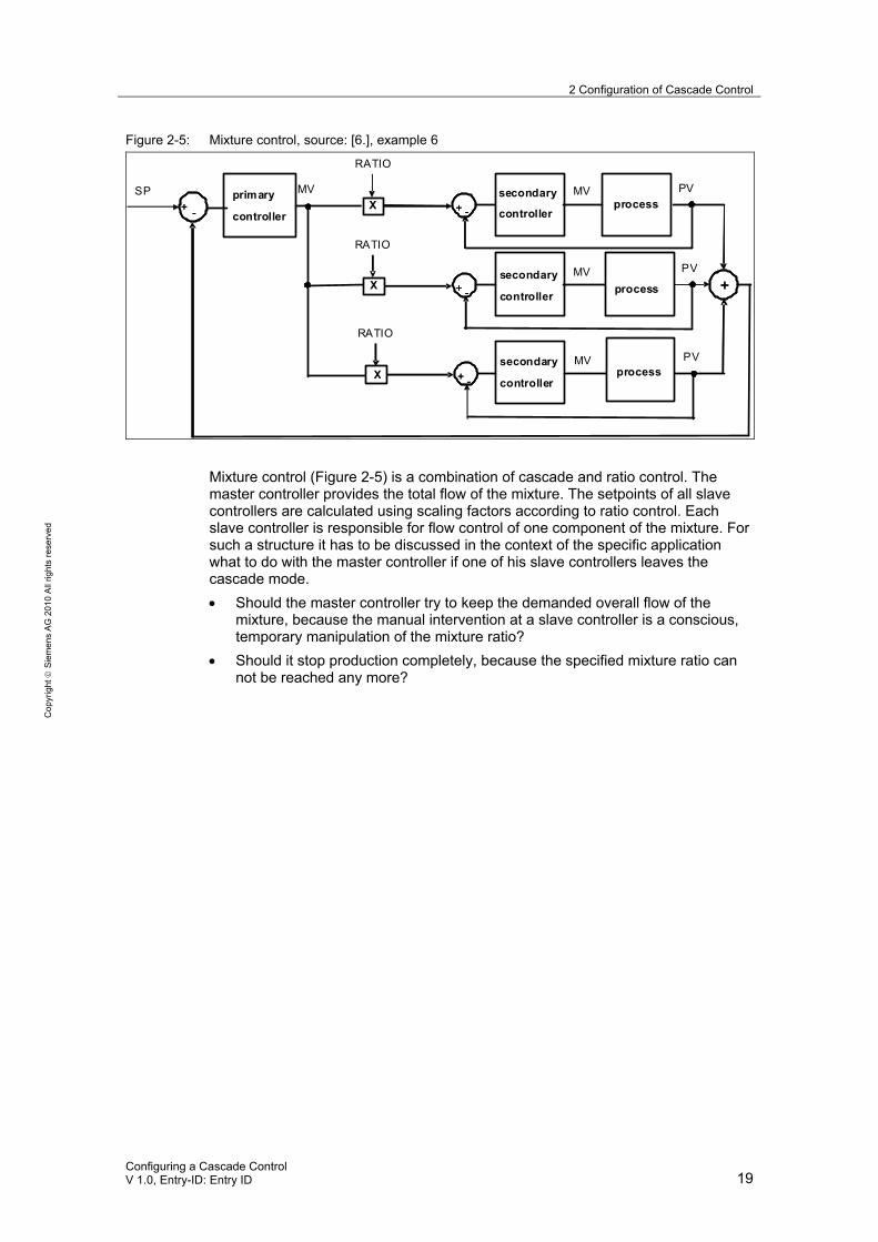
Figure 2-5: Mixture control, source: [6.], example 6
SP
+ - + - + -+ -
++
RATIO
PVMV
+ -+ -
PV
+ -+ -
PV
RATIO
RATIO
MV
MV
MV
primary
controller
secondary
controllerprocess
secondary
controllerprocess
secondary
controllerprocess
X
X
X
Mixture control (Figure 2-5) is a combination of cascade and ratio control. The master controller provides the total flow of the mixture. The setpoints of all slave controllers are calculated using scaling factors according to ratio control. Each slave controller is responsible for flow control of one component of the mixture. For such a structure it has to be discussed in the context of the specific application what to do with the master controller if one of his slave controllers leaves the cascade mode.
Should the master controller try to keep the demanded overall flow of the mixture, because the manual intervention at a slave controller is a conscious, temporary manipulation of the mixture ratio?
Should it stop production completely, because the specified mixture ratio can not be reached any more?

3 Simulation Example
20 Configuring a Cascade Control
V 1.0, Entrys-ID: Entry ID
Co
pyr
igh
t
Sie
me
ns
AG
20
10
All
righ
ts r
ese
rve
d
3 Simulation Example The following example shows a simulation of a Temperature cascade via Heating Medium Flow
Cascade temperature control via slave controller for heating and/or cooling medium flow is often used for tanks, reactors or columns, sometimes in combination with heat exchangers or cooling jackets, see e.g. Figure 1-2.
The plant unit “Cascade“ in the example project PL_Example_EU of PCS 7 Advanced Process Library contains simulation models for flow and temperature control systems with the parameters of the noise generator blocks.
Typical for this kind of applications is: The temperature control process is slower than the flow control process. The two time constants of the temperature control process are a far away from each other. There is an offset according to the environment temperature. The temperature control process shows less noise than the flow control process. Real world temperature control processes are typically much slower than this simulation, whereas the time constants of the flow control process are realistic.
In order to show how significant the improvement by cascade control is compared to single loop control, the time lags of the temperature simulation model are multiplied by factor 10 compared to APL_Example_EU. The controller parameters of the master and slave controller are calculated by PID-tuner (see Table 3-1). Using these new controller parameters a negative disturbance step change of 50 l/h was recorded.
Table 3-1: Process parameters of the modified cascade control example project
ProcSimC Flow control process Temperature control process
Gain 8 0,3
TimeLag1 1 s 80 s
TimeLag2 1 s 10 s
PV0 0 20
Noise Variance 0,22 0,1
Transitions between different operation modes can be tested using the simulation model. In addition, the performance of different parameter sets for master and slave controller can be tested.
The parameters in Table 3-2 below result in fast control performance with small control errors but strong control action. The PID master controller, designed by the PID-tuner for "fast temperature control systems", had the Gain = 104. This control design is intended for fast temperature control systems with binary actuators, e.g. electrical heating with semiconductor relays and pulse width modulation.
Such an aggressive design however results in very fast fluctuations of the manipulated variable of the master controller i.e. fast fluctuations of the setpoint of the slave controller which can not be followed fast enough. The slave control loop oscillates with a visible phase shift between setpoint and process variable. Therefore such aggressive controller designs are not suitable for master controllers of cascades. In the simulation example the gain was reduced to 20. In general this procedure (gain reduction by factor 2 to 5) is recommended if the PID-tuner for cascade master controllers suggests the “Design for fast temperature controllers”.

3 Simulation Example
Configuring a Cascade Control V 1.0, Entry-ID: Entry ID 21
Co
pyr
igh
t
Sie
me
ns
AG
20
10
All
righ
ts r
ese
rve
d
Table 3-2: Controller parameters for PID → PI cascade with fast dynamic performance
PID TIC-501 FIC-501
Gain 20 0,1
TI 45,3 s 1,8 s
TD 13,4 s 0
Figure 3-1: Setpoint step with PID→ PI Cascade
The parameters in the following tables have the advantage of smoother handling the actuator (e.g. valve), because the master controller has no differential action.
Table 3-3: Controller parameters for PI → P cascade with smooth actuator movements
PID TIC-501 FIC-501
Gain 26.0 0,1
TI 45,5 s 0 s
TD 0 s 0 s
Table 3-4: Controller parameters for PI → PI cascade with smooth actuator movements
PID TIC-501 FIC-501
Gain 26,0 0,1
TI 45,5 s 1,8 s
TD 0 s 0 s

3 Simulation Example
22 Configuring a Cascade Control
V 1.0, Entrys-ID: Entry ID
Co
pyr
igh
t
Sie
me
ns
AG
20
10
All
righ
ts r
ese
rve
d
In a further step the slave controller was bypassed, resulting in single loop PI control. With the help of the controller parameter were also determined by PID-Tuner (see Table 3-5) and the same disturbance step change was simulated as in the case of cascade control.
Table 3-5: Controller parameters for single loop PI-control
PID TIC-501 FIC-501
Gain 0,82 -
TI 56,9 s -
TD 0 s -
Figure 3-2: P I→ P cascade control with flow disturbance step change, shows a steady state control error between TIC.MV=FIC.SP and FIC.PV

3 Simulation Example
Configuring a Cascade Control V 1.0, Entry-ID: Entry ID 23
Co
pyr
igh
t
Sie
me
ns
AG
20
10
All
righ
ts r
ese
rve
d
Figure 3-3: PI → PI cascade control with flow disturbance step change, shows nearly no deviation from setpoint
Figure 3-4: Single loop controller with flow disturbance step change, shows the biggest deviation from setpoint
PI → PI cascade control provides the best results with respect to compensation of a disturbance variable step change in the slave control loop in this example. The

3 Simulation Example
24 Configuring a Cascade Control
V 1.0, Entrys-ID: Entry ID
Co
pyr
igh
t
Sie
me
ns
AG
20
10
All
righ
ts r
ese
rve
d
reason is that the time constant of the master control loop is much slower than that of the slave control loop. A disturbance inside the slave control loop is compensated by the integral action of this controller fast and precisely, such that the master control loop is not affected by the consequences of this disturbance. This is the desired effect of cascade control!
In case of the proportional-only slave controller however, the steady-state control error in the slave loop must be compensated by the master controller. Therefore the effect of the disturbance is a little more visible. Conclusion: a proportional-only slave controller is only recommended if the time constants of master and slave control loop are in the same order of magnitude (see APL_Example_EU and [1.]), because in such cases the integral actions of slave and master controller would interact with each other in an uncoordinated way.

4 Conclusion
Configuring a Cascade Control V 1.0, Entry-ID: Entry ID 25
Co
pyr
igh
t
Sie
me
ns
AG
20
10
All
righ
ts r
ese
rve
d
4 Conclusion If further process variables (auxiliary variables) besides the main controlled variable can be measured in a process, the application of cascade control can be advisable, because disturbances in slave control loops are recognized and compensated faster as this would be possible in the slower, main control loop.

5 Related Literature
26 Configuring a Cascade Control
V 1.0, Entrys-ID: Entry ID
Co
pyr
igh
t
Sie
me
ns
AG
20
10
All
righ
ts r
ese
rve
d
5 Related Literature [1.] Föllinger, O.
Regelungstechnik 8 überarbeitete Auflage Hüthig-Verlag, Heidelberg, 1994 ISBN 3-77852336-8, Kap. 7.10.1.
[2.] Dittmar, R., Pfeiffer, B-M. Modellbasierte prädiktive Regelung - Eine Einführung für Ingenieure. Oldenbourg Verlag, München, 2004 ISBN 3-486-27523-2, Kap. 1.2.2.
[3.] Müller, J., Pfeiffer, B-M., Hunger, V. Controlling with SIMATIC: Practice Book for SIMATIC S7 and SIMATIC PCS7 Control Systems. Publicis Corporate Publishing, Erlangen, 2005. ISBN 3-89578-255-6
[4.] Pfeiffer, B-M. PCS7 Solution-Template für Rührkesselreaktoren mit Mantelkühlung I IA&DT ATS 32 Karlsruhe, Feb. 2010.
[5.] Online-Help PCS 7 Advanced Process Library Chapter Templates/process tag types.
[6.] Manual SIMATIC Modular PID-Control Siemens A&D AS, Nov. 2003.

6 History
Configuring a Cascade Control V 1.0, Entry-ID: Entry ID 27
Co
pyr
igh
t
Sie
me
ns
AG
20
10
All
righ
ts r
ese
rve
d
6 History Table 6-1: History
Version Date Modifications
V1.0 May 2010 1st release