Embed Size (px)
Citation preview

Applikationen & Tools
Answers for industry.
Configuring the SIMATIC FM 350-2 Counter Module in SIMATIC PCS 7 SIMATIC PCS 7
Application Description December 2013

Warranty and liability
Counter Module SIMATIC FM 350-2 V1.0, Item ID: 83146298 2
Cop
yrig
ht
Sie
men
s A
G 2
013
All
right
s re
serv
ed
Warranty and liability
Note The Application Examples are not binding and do not claim to be complete regarding the circuits shown, equipping and any eventuality. The Application Examples do not represent customer-specific solutions. They are only intended to provide support for typical applications. You are responsible for ensuring that the described products are used correctly. These application examples do not relieve you of the responsibility to use safe practices in application, installation, operation and maintenance. When using these Application Examples, you recognize that we cannot be made liable for any damage/claims beyond the liability clause described. We reserve the right to make changes to these Application Examples at any time without prior notice. If there are any deviations between the recommendations provided in these application examples and other Siemens publications – e.g. Catalogs – the contents of the other documents have priority.
We do not accept any liability for the information contained in this document.
Any claims against us – based on whatever legal reason – resulting from the use of the examples, information, programs, engineering and performance data etc., described in this Application Example shall be excluded. Such an exclusion shall not apply in the case of mandatory liability, e.g. under the German Product Liability Act (“Produkthaftungsgesetz”), in case of intent, gross negligence, or injury of life, body or health, guarantee for the quality of a product, fraudulent concealment of a deficiency or breach of a condition which goes to the root of the contract (“wesentliche Vertragspflichten”). The damages for a breach of a substantial contractual obligation are, however, limited to the foreseeable damage, typical for the type of contract, except in the event of intent or gross negligence or injury to life, body or health. The above provisions do not imply a change of the burden of proof to your detriment. Any form of duplication or distribution of these Application Examples or excerpts hereof is prohibited without the expressed consent of Siemens Industry Sector.
Caution The functions and solutions described in this article confine themselves to the realization of the automation task predominantly. Please take into account furthermore that corresponding protective measures have to be taken up in the context of Industrial Security when connecting your equipment to other parts of the plant, the enterprise network or the Internet. Further information can be found under the item ID 50203404. http://support.automation.siemens.com/WW/view/en/50203404
Siemens Industry Online Support This article is taken from the Siemens Industry Online Support. The following link takes you directly to the download page of this document: http://support.automation.siemens.com/WW/view/en/83146298

Table of contents
Counter Module SIMATIC FM 350-2 V1.0, Item ID: 83146298 3
Cop
yrig
ht
Sie
men
s A
G 2
013
All
right
s re
serv
ed
Table of contents Warranty and liability ............................................................................................... 2 1 Task................................................................................................................. 4
1.1 Task .................................................................................................. 4 1.2 Solution ............................................................................................. 5 1.3 Hardware and software components .................................................. 6 1.3.1 Validity .............................................................................................. 6 1.3.2 Components used ............................................................................. 6
2 Basic principles of the counter module ........................................................ 8
2.1 Hardware information ........................................................................ 8 2.2 "Pcs7Cnt1" driver block ..................................................................... 9 2.3 Gate function of the counter channels – Activating, interrupting
and canceling a channel .................................................................. 10 2.3.1 Overview ......................................................................................... 10 2.3.2 Interrupting and canceling a counting mode ..................................... 11 2.3.3 Interrupting a measuring mode ........................................................ 12 2.4 Counting rages of the module channels ........................................... 13 2.5 Operating modes for the channels ................................................... 14 2.5.1 Introduction to counting.................................................................... 14 2.5.2 Continuous counting ........................................................................ 15 2.5.3 Single Counting ............................................................................... 16 2.5.4 Periodic counting ............................................................................. 17 2.5.5 Frequency measurement ................................................................. 18 2.5.6 Rotational speed measurement ....................................................... 18 2.5.7 Time period measurement ............................................................... 19
3 Configuration ................................................................................................ 20
3.1 Requirements for configuring the counter module ............................ 20 3.2 Configuring the counter module in HW Config .................................. 26 3.3 Creating data areas in the symbol table ........................................... 30 3.4 Adding a driver block in the master data library ................................ 33 3.5 Connecting a channel data area to the driver block .......................... 35 3.6 Configuring the counter module channels ........................................ 40 3.6.1 Continuous counting ........................................................................ 40 3.6.2 Single/Periodic counting .................................................................. 44 3.6.3 Measurements ................................................................................. 49 3.6.4 Hardware gate ................................................................................. 54 3.6.5 Canceling or interrupting the counting function ................................. 58 3.6.6 Count direction ................................................................................ 62 3.6.7 Loading values ................................................................................ 66 3.6.8 Comparing the counter reading with a value .................................... 68 3.6.9 Extending the counter limits ............................................................. 72
4 Related literature .......................................................................................... 79 5 History .......................................................................................................... 79

1 Task
Counter Module SIMATIC FM 350-2 V1.0, Item ID: 83146298 4
Cop
yrig
ht
Sie
men
s A
G 2
013
All
right
s re
serv
ed
1 Task 1.1 Task
Every automated system involves counting, dosing, or measuring. Sensors and actuators supply signals that are read and evaluated by an automation system (AS). Every CPU can load inputs and outputs into the internal memory when an operation block (OB) is called. This internal memory is named process image. When an OB is started, the process image output (PIQ) is outputted and the process image input (PII) is updated before the processing of the code is starting. The other way is to read the signals via the address range of the peripherals. In this case, the module data is loaded and processed when the block or a function is called. Just as with the inputs, the outputs can also be directly written via the peripherals. The advantage of peripheral addresses is that changes can also be processed after the process image has been read. Figure 1–1 shows the execution of an OB. It illustrates the writing of the outputs (PIQ) and reading of the inputs into the PII at the start of the cycle. After this the program code is edited for example by a function block (FB). If an input signal changes during program processing, this change is not applied to the process image. For the called FB (Figure 1–1), this means that the block is processed using the values from the process image. If you use a peripheral address for the input, the input is read by the call of the FB, and the function block will have the current value. Figure 1–1: Signal processing in an OB cycle
In tasks with very frequently edges, it is possible the edges get lost as a result of an exceedingly long OB processing time. In the case that a positive and a negative edge occurs during processing, this fluctuation is very difficult to record even when using peripheral inputs. The AS has to read the input whenever the signal changes. The following figure illustrates how a changing input signal provides the same measurement result every time the input is read.

1 Task
Counter Module SIMATIC FM 350-2 V1.0, Item ID: 83146298 5
Cop
yrig
ht
Sie
men
s A
G 2
013
All
right
s re
serv
ed
Figure 1–2: Reading the input signal
The challenge is to find a solution that provides an undistorted result of a measurement. This means that every edge must be registered by the AS while counting, for example, beverage crates do not contain one bottle too many or too few.
1.2 Solution
One possibility for the measurement of signals is the use of the SIMATIC FM 350-2 counter module. With its integration you can realize the following tasks for process automation: Measurement of flow quantity Measurement of rotational speed
Typical tasks for counter modules are: Continuous counting up/down Single counting up/down Periodic counting up/down Frequency measurement Rotational speed measurement Time period measurement Dosing
You can start and stop the count process either via the user program (software) or via external signals (hardware). Count, gate and direction signals can be connected directly to the counter module.
Advantages of the counter module The counter module can measure signals independent of the CPU. All edges up to 20 kHz are reliably detected. The current counter values can be read out by the automation system at any
time. The independent configuration of up to eight channels is possible. The current counter reading can be compared to a value within the module. In
the case of true comparison, the counter module output is activated.

1 Task
Counter Module SIMATIC FM 350-2 V1.0, Item ID: 83146298 6
Cop
yrig
ht
Sie
men
s A
G 2
013
All
right
s re
serv
ed
Delimitation The following components of the FM 350-2 counter module and the accompanying driver are not covered in this application: Dosing counter Triggering hardware interrupts Rotary encoder Substitute values
Note Additional project-specific information can be found in the "SIMATIC S7-300 FM 350-2 Counter Module" manual.
The link to the entry in the Industry Online Support is as follows: http://support.automation.siemens.com/WW/view/en/1105178
1.3 Hardware and software components
1.3.1 Validity
This application applies to: SIMATIC PCS 7 V8.0 SP1 SIMATIC FM 350-2 firmware version V6.0 and higher
1.3.2 Components used
The application has been created with the following components:
Hardware components Table 1–1: Hardware components used
Component No. Order no. Note
FM 350-2 1 6ES7 350-2AH00-0AE0 Alternatively, newer versions of the module can be used.
CPU 417-4 H with CP 443-1
1 6ES7 417-4HT14-0AB0 6GK7 443-1EX20-0XE0
The CPU was not used redundantly, but rather as an individual automation station for the test environment.
ET 200M 1 6ES7 153-2BA01-0XB0 Test environment component
DO8xDC24V/2A 2 6ES7 322-1BF01-0AA0 Test environment component

1 Task
Counter Module SIMATIC FM 350-2 V1.0, Item ID: 83146298 7
Cop
yrig
ht
Sie
men
s A
G 2
013
All
right
s re
serv
ed
Software components Table 1–2: Software components used
Component No. Order no. Note
SIMATIC PCS 7 V8.0
1 6ES7658-5AX08-0YA5 V8.0 SP1
FM Configuration Package
1 - The configuration interface is supplied with the counter module or can be found in the following entry: http://support.automation.siemens.com/WW/view/en/60237759

2 Basic principles of the counter module
Counter Module SIMATIC FM 350-2 V1.0, Item ID: 83146298 8
Cop
yrig
ht
Sie
men
s A
G 2
013
All
right
s re
serv
ed
2 Basic principles of the counter module This chapter contains the essential information on the counter module.
Note Further information about the FM 350-2 counter module can be found in the "S7-300 Counter Module FM 350-2" manual.
The link to the entry in the Industry Online Support is as follows: http://support.automation.siemens.com/WW/view/en/1105178
2.1 Hardware information
Each of the counter module's eight channels has three digital inputs and one digital output. The counter module's signal inputs are labeled with the letter A, the direction input with the letter B, the hardware gate with the letter I and the output with the letter Q. The number after the letter indicates the channel to which the connection is assigned. For example, B5 is the direction input of the counter module's 5th channel. The inputs for direction, hardware gate and output are optional and do not need to be connected. Figure 2–1: Hardware scheme of the counter module
2 Basic principles of the counter module
Counter Module SIMATIC FM 350-2 V1.0, Item ID: 83146298 9
Cop
yrig
ht
Sie
men
s A
G 2
013
All
right
s re
serv
ed
2.2 "Pcs7Cnt1" driver block
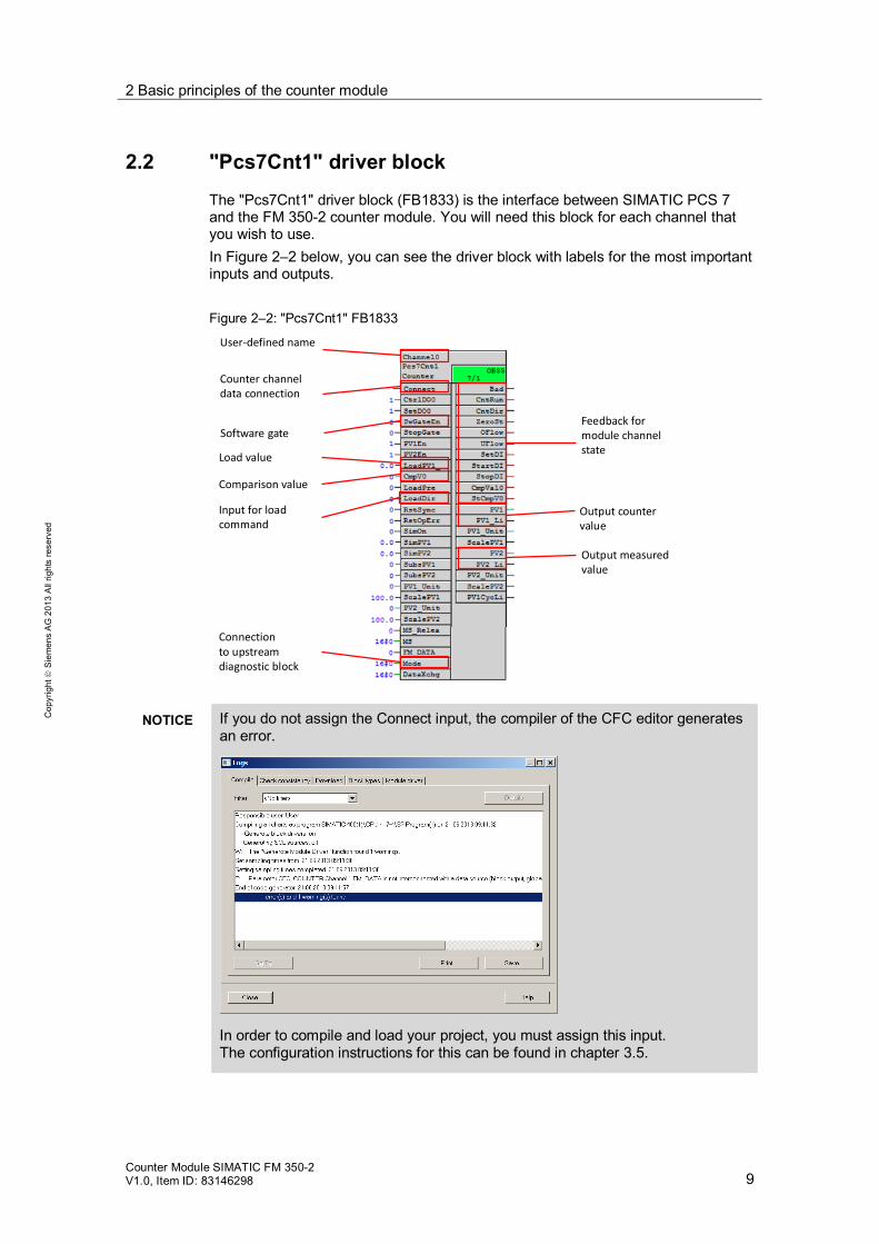
The "Pcs7Cnt1" driver block (FB1833) is the interface between SIMATIC PCS 7 and the FM 350-2 counter module. You will need this block for each channel that you wish to use. In Figure 2–2 below, you can see the driver block with labels for the most important inputs and outputs. Figure 2–2: "Pcs7Cnt1" FB1833
User-defined name
Counter channel data connection
Software gate
Comparison value
Output counter value
Output measured value
Load value
Input for load command
Feedback for module channel state
Connection to upstreamdiagnostic block
NOTICE If you do not assign the Connect input, the compiler of the CFC editor generates an error.
In order to compile and load your project, you must assign this input. The configuration instructions for this can be found in chapter 3.5.

2 Basic principles of the counter module
Counter Module SIMATIC FM 350-2 V1.0, Item ID: 83146298 10
Cop
yrig
ht
Sie
men
s A
G 2
013
All
right
s re
serv
ed
2.3 Gate function of the counter channels – Activating, interrupting and canceling a channel
2.3.1 Overview
In order to activate the function of a counter module channel, the internal gate must be set. The internal gate consists of a software gate and a hardware gate that are connected by a logical AND. The software gate is an interface of the "Pcs7Cnt1" driver block, and the hardware gate is a digital input on the module. The hardware gate is deactivated in the basic setting and can be separately activated for each channel in the hardware configuration. The software gate does not have a deactivation function similar to the one available for the hardware gate. Figure 2–3: Digital logic with function table for the gate function
Note The configuration instructions for activating the hardware gate can be found in chapter 3.6.4.

2 Basic principles of the counter module
Counter Module SIMATIC FM 350-2 V1.0, Item ID: 83146298 11
Cop
yrig
ht
Sie
men
s A
G 2
013
All
right
s re
serv
ed
2.3.2 Interrupting and canceling a counting mode
The operating modes for counting are: continuous, single and periodic counting. These modes are active as long as the internal gate setting is TRUE. By default, the counting modes are canceled when the internal gate is set to FALSE. When the gate is set to FALSE, the function of the channel is canceled by default. Canceled means that the value currently being counted is overwritten by the start value when the channel is re-activated. The default start value is 0. It is possible to set the properties to interrupt instead of cancel in the configuration interface. This only applies to the counting functions. If the setting is configured to interrupt, then counting will continue from the existing value in the counter when a reactivation occurs. Table 2–1: Overview of counter behavior when the internal gate is set and the hardware
gate has not been activated in the configuration.
Configuration SW gate Internal gate
Behavior
Canceling Set to TRUE
The start value is loaded. Counting begins from this value.
Interrupting
Counting continues from the current count.
= positive edge If you wish to also use the hardware gate, there is an anomaly in the canceling behavior of the counter channel. Here, the current count is only overwritten if a positive edge causes the internal gate to be set at the hardware gate. Table 2–2: Overview of counter behavior when the internal gate is set. The hardware gate
has been activated in the configuration.
Configuration SW gate HW gate Internal gate
Behavior
Canceling 1
Set to TRUE
Counting continues from the current count.
1
The start value is loaded. Counting begins from this value.
Interrupting 1
Counting continues from the current count.
1
- positive edge
Note A description of the configuration can be found in chapter 3.6.4.
2 Basic principles of the counter module
Counter Module SIMATIC FM 350-2 V1.0, Item ID: 83146298 12
Cop
yrig
ht
Sie
men
s A
G 2
013
All
right
s re
serv
ed
2.3.3 Interrupting a measuring mode
The operating modes for measuring are: frequency, rotational speed and time period measurement. A measurement is activated as long as the internal gate is active. When the internal gate is set to FALSE, the channel is deactivated. The driver block's measurement output provides the old measured value until the next activation of the channel. Here, the selection of interrupt or cancel is not possible.
Note In the first measuring cycle, the measured value output is "-1". The reason for this feature is so that the first measuring cycle can be differentiated from the real system values that are either "0" or greater.
2 Basic principles of the counter module
Counter Module SIMATIC FM 350-2 V1.0, Item ID: 83146298 13
Cop
yrig
ht
Sie
men
s A
G 2
013
All
right
s re
serv
ed
2.4 Counting rages of the module channels
Channels 0-3 Channels 0-3 are read via the process image input of the called OB. The counting range of these channels can be changed in the HW configuration of the counter module.
Note The instructions for the configuration can be found in chapter 3.6.9
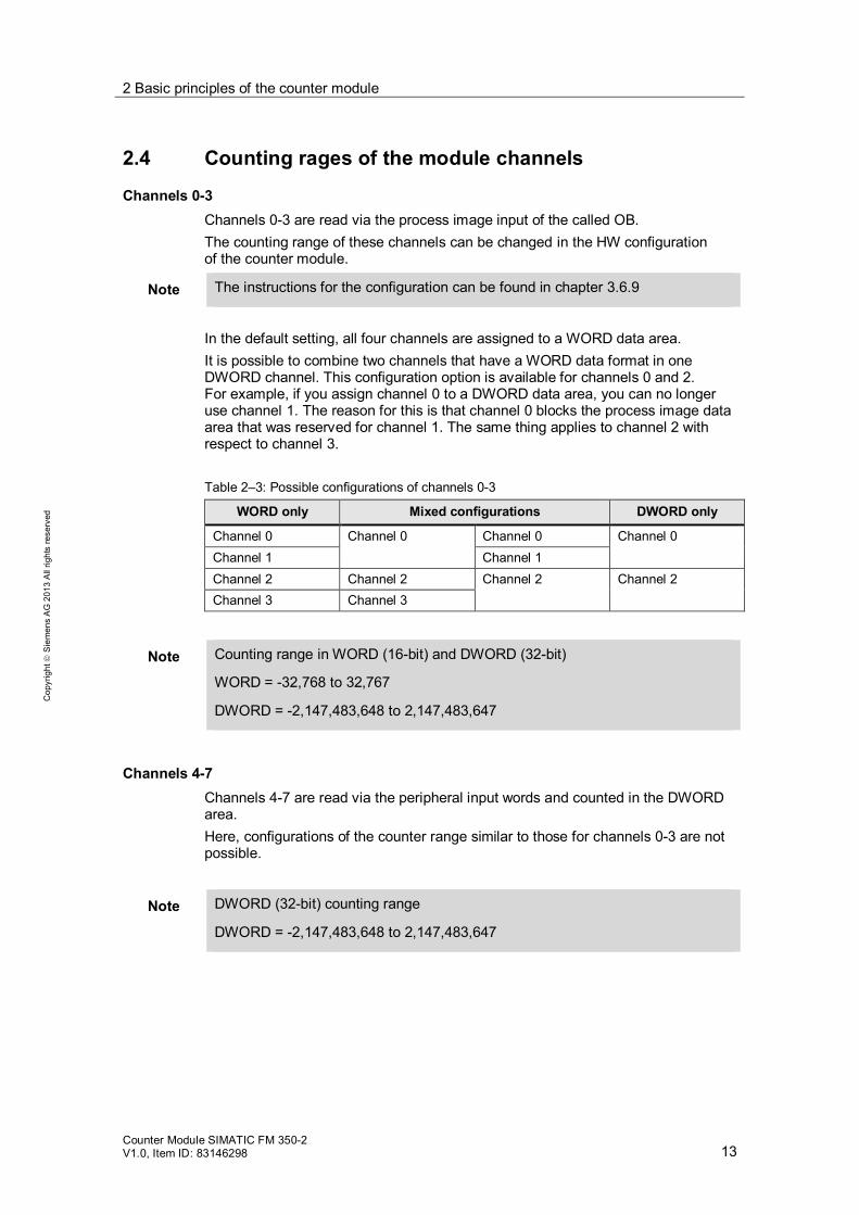
In the default setting, all four channels are assigned to a WORD data area. It is possible to combine two channels that have a WORD data format in one DWORD channel. This configuration option is available for channels 0 and 2. For example, if you assign channel 0 to a DWORD data area, you can no longer use channel 1. The reason for this is that channel 0 blocks the process image data area that was reserved for channel 1. The same thing applies to channel 2 with respect to channel 3. Table 2–3: Possible configurations of channels 0-3
WORD only Mixed configurations DWORD only
Channel 0 Channel 0 Channel 0 Channel 0 Channel 1 Channel 1 Channel 2 Channel 2 Channel 2 Channel 2 Channel 3 Channel 3
Note Counting range in WORD (16-bit) and DWORD (32-bit)
WORD = -32,768 to 32,767
DWORD = -2,147,483,648 to 2,147,483,647
Channels 4-7 Channels 4-7 are read via the peripheral input words and counted in the DWORD area. Here, configurations of the counter range similar to those for channels 0-3 are not possible.
Note DWORD (32-bit) counting range
DWORD = -2,147,483,648 to 2,147,483,647

2 Basic principles of the counter module
Counter Module SIMATIC FM 350-2 V1.0, Item ID: 83146298 14
Cop
yrig
ht
Sie
men
s A
G 2
013
All
right
s re
serv
ed
2.5 Operating modes for the channels
2.5.1 Introduction to counting
In the sections below, the following counting functions are explained in greater detail: Continuous counting Single count Periodic counting
Each time a positive edge is registered by the counter module, the module increases the value by a count of one. If the count direction "down" is selected, it decreases the value by one. Below you can see a diagram with the input signal and the counter reading. This is an example intended to illustrate that irregular signals can also be present. In the following chapters, the count will be portrayed using regular signals. Figure 2–4: Behavior of the counter reading in relation to the input signal
2 Basic principles of the counter module
Counter Module SIMATIC FM 350-2 V1.0, Item ID: 83146298 15
Cop
yrig
ht
Sie
men
s A
G 2
013
All
right
s re
serv
ed
2.5.2 Continuous counting
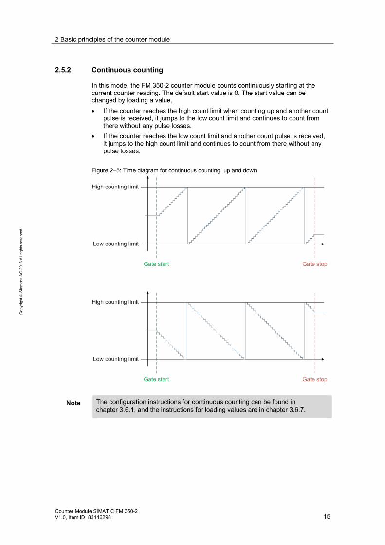
In this mode, the FM 350-2 counter module counts continuously starting at the current counter reading. The default start value is 0. The start value can be changed by loading a value. If the counter reaches the high count limit when counting up and another count
pulse is received, it jumps to the low count limit and continues to count from there without any pulse losses.
If the counter reaches the low count limit and another count pulse is received, it jumps to the high count limit and continues to count from there without any pulse losses.
Figure 2–5: Time diagram for continuous counting, up and down
Note The configuration instructions for continuous counting can be found in chapter 3.6.1, and the instructions for loading values are in chapter 3.6.7.
2 Basic principles of the counter module
Counter Module SIMATIC FM 350-2 V1.0, Item ID: 83146298 16
Cop
yrig
ht
Sie
men
s A
G 2
013
All
right
s re
serv
ed
2.5.3 Single Counting
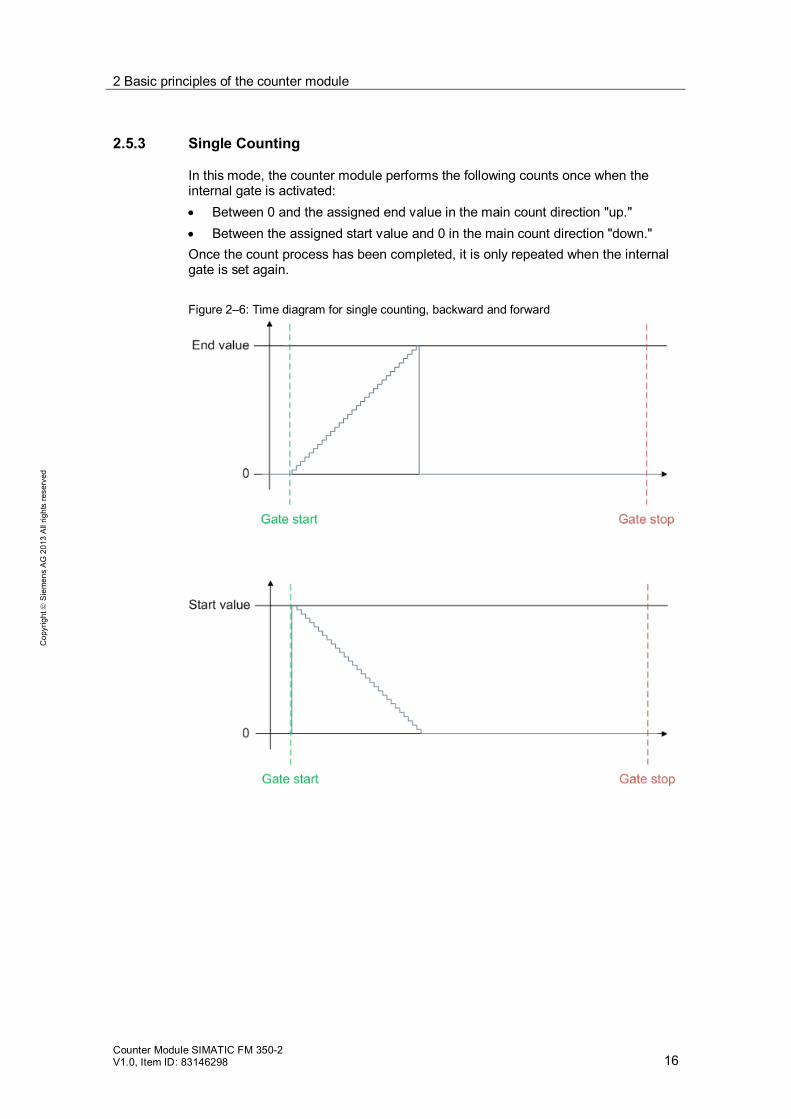
In this mode, the counter module performs the following counts once when the internal gate is activated: Between 0 and the assigned end value in the main count direction "up." Between the assigned start value and 0 in the main count direction "down."
Once the count process has been completed, it is only repeated when the internal gate is set again. Figure 2–6: Time diagram for single counting, backward and forward
2 Basic principles of the counter module
Counter Module SIMATIC FM 350-2 V1.0, Item ID: 83146298 17
Cop
yrig
ht
Sie
men
s A
G 2
013
All
right
s re
serv
ed
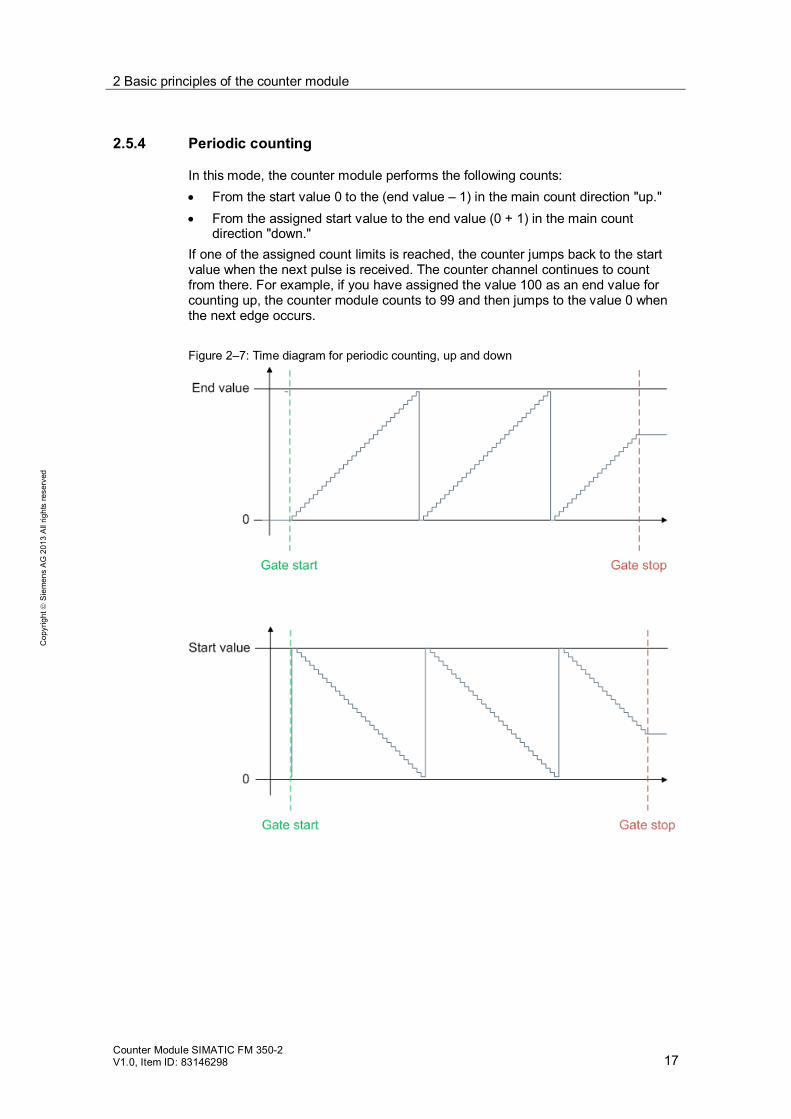
2.5.4 Periodic counting
In this mode, the counter module performs the following counts: From the start value 0 to the (end value – 1) in the main count direction "up." From the assigned start value to the end value (0 + 1) in the main count
direction "down." If one of the assigned count limits is reached, the counter jumps back to the start value when the next pulse is received. The counter channel continues to count from there. For example, if you have assigned the value 100 as an end value for counting up, the counter module counts to 99 and then jumps to the value 0 when the next edge occurs. Figure 2–7: Time diagram for periodic counting, up and down

2 Basic principles of the counter module
Counter Module SIMATIC FM 350-2 V1.0, Item ID: 83146298 18
Cop
yrig
ht
Sie
men
s A
G 2
013
All
right
s re
serv
ed
2.5.5 Frequency measurement
In this mode, the FM 350-2 counter module counts the pulses received within a predetermined time window. This is then used to calculate the frequency. It is important to note that the calculated value is only available and able to be output after the first measuring cycle. During the first time window, the output is -1. The reason for this feature is so that the first measuring cycle can be differentiated from the real system values that are either "0" or greater. The measured value is output in mHz at the driver block. Figure 2–8: Time diagram for frequency measurement
2.5.6 Rotational speed measurement
In this mode, which is virtually identical to the "frequency measurement" mode, the FM 350-2 counts the pulses received from a signal transmitter within a predetermined time window and uses this to calculate the rotational speed. Here, the measured value from the first cycle is once again only available in the second time window. The rotational speed is output in 10-3 min-1 at the driver block.
2 Basic principles of the counter module
Counter Module SIMATIC FM 350-2 V1.0, Item ID: 83146298 19
Cop
yrig
ht
Sie
men
s A
G 2
013
All
right
s re
serv
ed
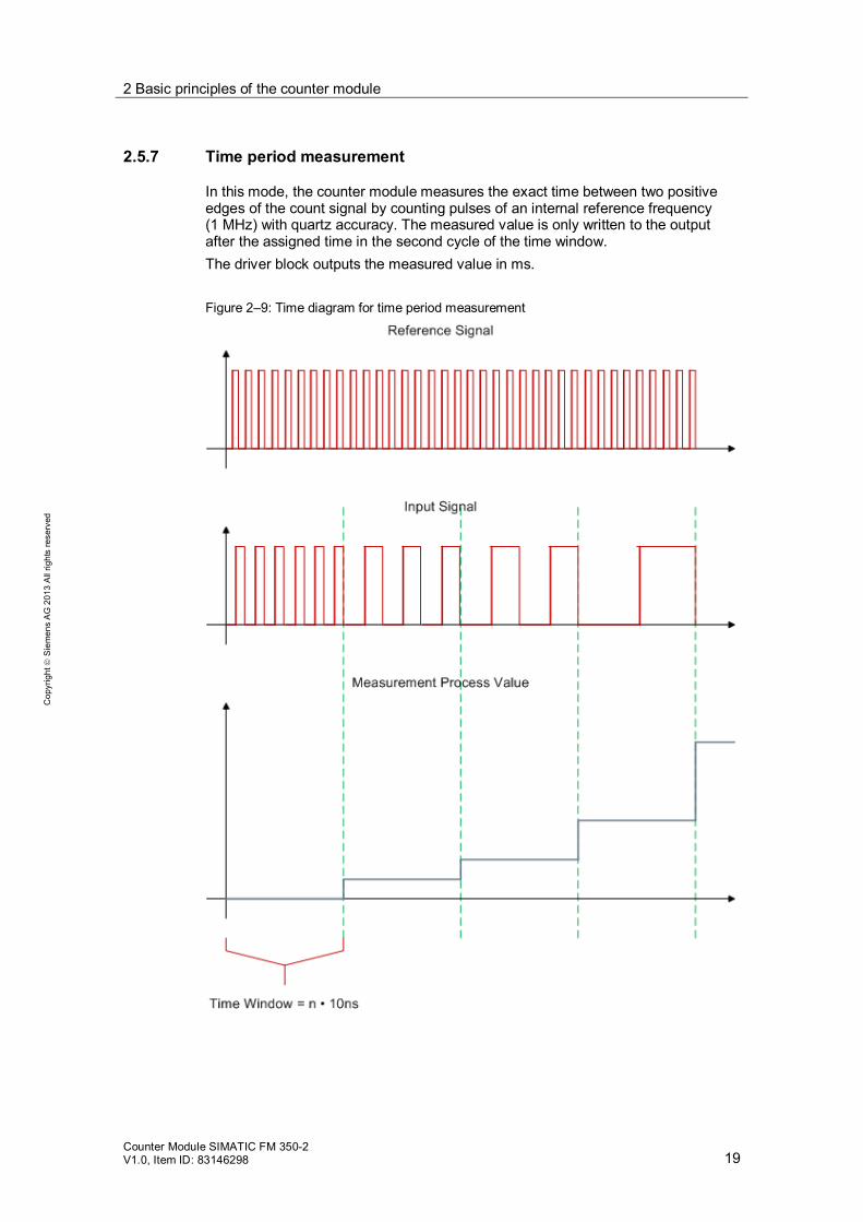
2.5.7 Time period measurement
In this mode, the counter module measures the exact time between two positive edges of the count signal by counting pulses of an internal reference frequency (1 MHz) with quartz accuracy. The measured value is only written to the output after the assigned time in the second cycle of the time window. The driver block outputs the measured value in ms. Figure 2–9: Time diagram for time period measurement
3 Configuration
Counter Module SIMATIC FM 350-2 V1.0, Item ID: 83146298 20
Cop
yrig
ht
Sie
men
s A
G 2
013
All
right
s re
serv
ed
3 Configuration 3.1 Requirements for configuring the counter module
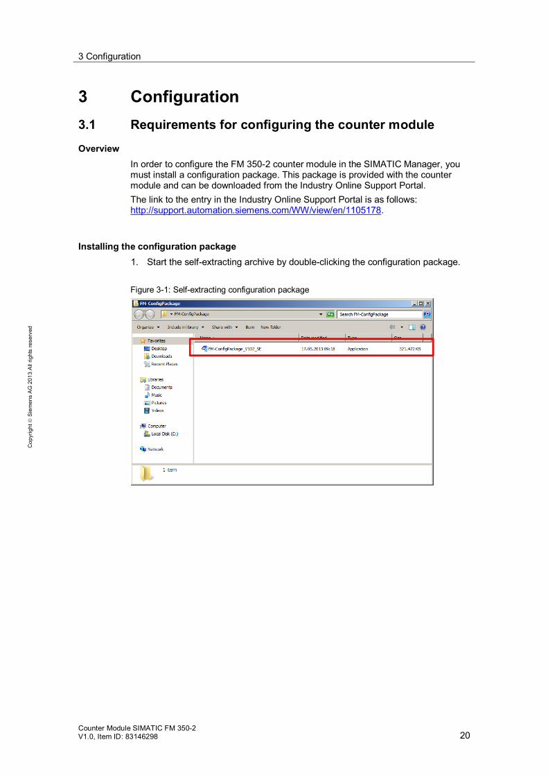
Overview In order to configure the FM 350-2 counter module in the SIMATIC Manager, you must install a configuration package. This package is provided with the counter module and can be downloaded from the Industry Online Support Portal. The link to the entry in the Industry Online Support Portal is as follows: http://support.automation.siemens.com/WW/view/en/1105178.
Installing the configuration package 1. Start the self-extracting archive by double-clicking the configuration package. Figure 3-1: Self-extracting configuration package

3 Configuration
Counter Module SIMATIC FM 350-2 V1.0, Item ID: 83146298 21
Cop
yrig
ht
Sie
men
s A
G 2
013
All
right
s re
serv
ed
2. Select the destination file at the dialog window. 3. Start the file extraction by clicking on the "Unzip" button.
Once the extraction has been successfully completed, the "WinZip Self-Extractor" dialog window opens.
Figure 3-2: Extracting the installation files
4. Click the "OK" button.
Close the dialog window for the file extraction by clicking on the "Close" button. Figure 3-3: Dialog window following successful extraction

3 Configuration
Counter Module SIMATIC FM 350-2 V1.0, Item ID: 83146298 22
Cop
yrig
ht
Sie
men
s A
G 2
013
All
right
s re
serv
ed
5. Launch the setup.exe file by double-clicking it in the destination folder. Figure 3-4: Setup.exe after extraction of the configuration package
6. Select the setup language and then click the "Next >" button. Figure 3-5

3 Configuration
Counter Module SIMATIC FM 350-2 V1.0, Item ID: 83146298 23
Cop
yrig
ht
Sie
men
s A
G 2
013
All
right
s re
serv
ed
7. Read the installation instructions and then click the "Next >" button. Figure 3-6
8. Read the product notes in the readme file and click the "Next >" button. Figure 3-7: Product information

3 Configuration
Counter Module SIMATIC FM 350-2 V1.0, Item ID: 83146298 24
Cop
yrig
ht
Sie
men
s A
G 2
013
All
right
s re
serv
ed
9. Read the license agreement. If you agree to the conditions, select the check box and click the "Next >" button.
Figure 3-8: License agreement
10. Select the check box for the FM 350-2 counter module from the list and then
click the "Next >" button. Installation begins.
Figure 3-9: Selection of modules for installation

3 Configuration
Counter Module SIMATIC FM 350-2 V1.0, Item ID: 83146298 25
Cop
yrig
ht
Sie
men
s A
G 2
013
All
right
s re
serv
ed
1. Once the installation has been successfully completed, click the "Finish" button.
Figure 3–10: Successfully completing installation
3 Configuration
Counter Module SIMATIC FM 350-2 V1.0, Item ID: 83146298 26
Cop
yrig
ht
Sie
men
s A
G 2
013
All
right
s re
serv
ed
3.2 Configuring the counter module in HW Config
Requirements SIMATIC PCS 7 project Your hardware is configured outside of the FM 350-2 counter module.
Procedure
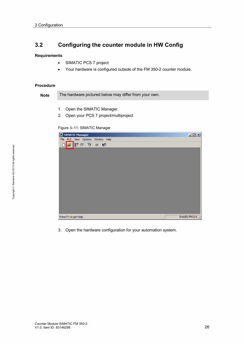
1. Open the SIMATIC Manager. 2. Open your PCS 7 project/multiproject Figure 3–11: SIMATIC Manager
3. Open the hardware configuration for your automation system.
Note The hardware pictured below may differ from your own.

3 Configuration
Counter Module SIMATIC FM 350-2 V1.0, Item ID: 83146298 27
Cop
yrig
ht
Sie
men
s A
G 2
013
All
right
s re
serv
ed
4. Select the ET 200M into which the counter module is to be integrated.
Figure 3–12: HW Config – Selected interface module (IM)
5. In the "PCS7_V80" profile of the hardware catalog, search for the FM 350-2 counter module.
6. Drag the FM 350-2 counter module from the catalog to the next free slot of the ET 200M.
Figure 3-13 Counter module in the HW Config

3 Configuration
Counter Module SIMATIC FM 350-2 V1.0, Item ID: 83146298 28
Cop
yrig
ht
Sie
men
s A
G 2
013
All
right
s re
serv
ed
7. Open the module configuration window by double-clicking the FM 350-2 counter module. When you first open the configuration window, the "Specify Channels" menu interface is displayed. Keep the default settings and click on the "OK" button.
Figure 3–14: Channel specification for the FM 350-2 counter module
Note If the following window is displayed when you open the configuration interface for the FM 350-2 counter module, click the "OK" button:
When you click the "OK" button, the configuration is saved and the configuration interface opens.
If you click "Cancel," the interface does not open.

3 Configuration
Counter Module SIMATIC FM 350-2 V1.0, Item ID: 83146298 29
Cop
yrig
ht
Sie
men
s A
G 2
013
All
right
s re
serv
ed
8. Save the default settings and close the window.
Figure 3–15: Configuration interface for the 350-2 counter module
9. Save and compile your hardware configuration. 10. Load your configuration to your automation system.
Figure 3–16: HW Config

3 Configuration
Counter Module SIMATIC FM 350-2 V1.0, Item ID: 83146298 30
Cop
yrig
ht
Sie
men
s A
G 2
013
All
right
s re
serv
ed
3.3 Creating data areas in the symbol table
Requirements Hardware has been successfully configured. Your modules do not have any errors after the hardware configuration is
loaded.
Addressing channels The channels in the process image are addressed as described in the online help for the "Pcs7Cnt1" driver block (FB1833). In the following example, the start address 512 is used.
Note The start address can be found in the HW configuration.
It is the first address displayed in the input range.
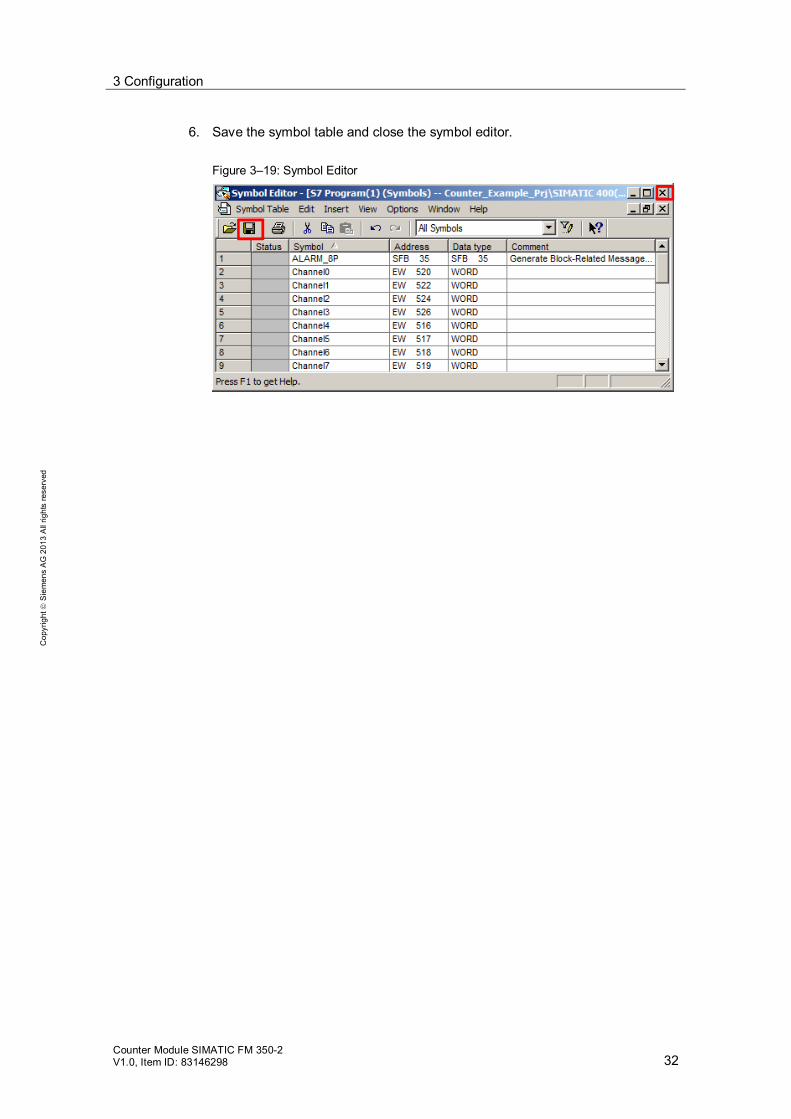
Channels in the process image: Channel 0: Start address + 8 bytes = EW 520 Channel 1: Start address + 10 bytes = EW 522 Channel 2: Start address + 12 bytes = EW 524 Channel 3: Start address + 14 bytes = EW 526
Note You can find information on the use of DWORD data formats in chapter 3.6.9.
Channels outside of the process image: Channel 4: Start address + 4 bytes = EW 516 Channel 5: Start address + 5 bytes = EW 517 Channel 6: Start address + 6 bytes = EW 518 Channel 7: Start address + 7 bytes = EW 519 The following applies for the addressing of these channels (4-7): start address of the counter module + channel number.

3 Configuration
Counter Module SIMATIC FM 350-2 V1.0, Item ID: 83146298 31
Cop
yrig
ht
Sie
men
s A
G 2
013
All
right
s re
serv
ed
Procedure 2. Open the component view of your project. 3. Select the S7 program of your automation system.
Figure 3–17: Symbol table in the component view
4. Open the symbol table by double-clicking on the icon. 5. Enter the channel addresses in the symbol table.
Note The contents of your symbol table may be different from the contents pictured.
Figure 3–18: Changes in the symbol table
3 Configuration
Counter Module SIMATIC FM 350-2 V1.0, Item ID: 83146298 32
Cop
yrig
ht
Sie
men
s A
G 2
013
All
right
s re
serv
ed
6. Save the symbol table and close the symbol editor.
Figure 3–19: Symbol Editor

3 Configuration
Counter Module SIMATIC FM 350-2 V1.0, Item ID: 83146298 33
Cop
yrig
ht
Sie
men
s A
G 2
013
All
right
s re
serv
ed
3.4 Adding a driver block in the master data library
Requirements You have a master data library. "PCS 7 AP Library Vxx" is not used as the master data library.
Procedure 1. In the "File" menu, select the "Open" command.
The "Open Project" dialog box is displayed. 2. Open the "Libraries" tab. 3. Select the "PCS 7 AP Library V80" library and your master data library from the
list.
Figure 3–20: Library selection
4. Click the "OK" button. The libraries are opened in the component view. 5. In the tree view, select the entry labeled "PCS 7 AP Library V80\Blocks +
Templates\Blocks".
3 Configuration
Counter Module SIMATIC FM 350-2 V1.0, Item ID: 83146298 34
Cop
yrig
ht
Sie
men
s A
G 2
013
All
right
s re
serv
ed
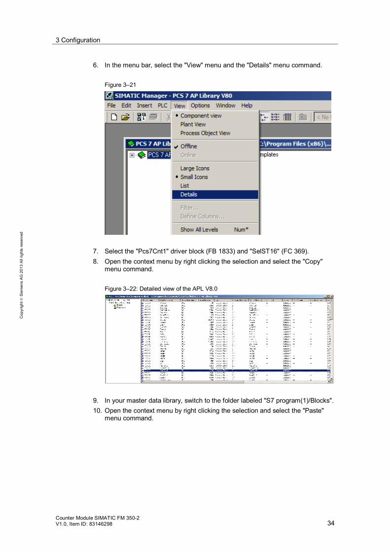
6. In the menu bar, select the "View" menu and the "Details" menu command.
Figure 3–21
7. Select the "Pcs7Cnt1" driver block (FB 1833) and "SelST16" (FC 369). 8. Open the context menu by right clicking the selection and select the "Copy"
menu command.
Figure 3–22: Detailed view of the APL V8.0
9. In your master data library, switch to the folder labeled "S7 program(1)/Blocks". 10. Open the context menu by right clicking the selection and select the "Paste"
menu command.

3 Configuration
Counter Module SIMATIC FM 350-2 V1.0, Item ID: 83146298 35
Cop
yrig
ht
Sie
men
s A
G 2
013
All
right
s re
serv
ed
3.5 Connecting a channel data area to the driver block
Requirements Hardware has been successfully configured. Addresses have been entered in the symbol table. The driver block is in the master data library.
Procedure 1. Open the technology view of your project. 2. Optional: Generate your CFC chart for the driver block if it does not already
exist. 3. Open the CFC chart in which the driver block is to be used. 4. In the catalog, switch to the "Libraries" tab. 5. In the navigation pane, open the "S7 Program (1)/Blocks/Channel" folder in
your project library. 6. Drag the "Pcs7Cnt1" driver block to the desired location in the CFC chart.
Figure 3–23: CFC editor – Adding the driver block
Note In the default setting, OB30 through OB38 are recommended for the use of the "Pcs7Cnt1" driver block.
3 Configuration
Counter Module SIMATIC FM 350-2 V1.0, Item ID: 83146298 36
Cop
yrig
ht
Sie
men
s A
G 2
013
All
right
s re
serv
ed
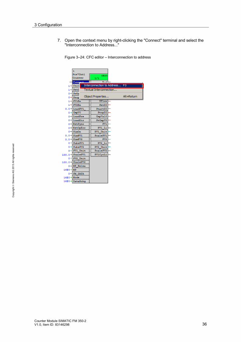
7. Open the context menu by right-clicking the "Connect" terminal and select the "Interconnection to Address..."
Figure 3–24: CFC editor – Interconnection to address

3 Configuration
Counter Module SIMATIC FM 350-2 V1.0, Item ID: 83146298 37
Cop
yrig
ht
Sie
men
s A
G 2
013
All
right
s re
serv
ed
8. Select the data area of the channel you wish to interconnect with the driver block. Figure 3–25: Selecting the addresses
Figure 3–26: Input word connected to the driver block

3 Configuration
Counter Module SIMATIC FM 350-2 V1.0, Item ID: 83146298 38
Cop
yrig
ht
Sie
men
s A
G 2
013
All
right
s re
serv
ed
9. Compile your CFC chart. If the connection was successful, you will not receive any error messages and additional interconnections will be created as pictured below. Figure 3–27: Successful compilation of the driver block
Note If the new interconnections are not immediately displayed, refresh the CFC chart using the "F5" button.

3 Configuration
Counter Module SIMATIC FM 350-2 V1.0, Item ID: 83146298 39
Cop
yrig
ht
Sie
men
s A
G 2
013
All
right
s re
serv
ed
Note If you receive an error message stating that the FM_DATA connection cannot be interconnected by your driver block, check your data area again and save and compile your hardware settings for the FM 350-2 counter module.
10. Once the compilation has been successfully completed, load the CFC chart to
your automation system. Figure 3–28: CFC editor – Compiling and loading

3 Configuration
Counter Module SIMATIC FM 350-2 V1.0, Item ID: 83146298 40
Cop
yrig
ht
Sie
men
s A
G 2
013
All
right
s re
serv
ed
3.6 Configuring the counter module channels
The following nine chapters are comprised of selectable modular configurations for the individual channels of the FM 350-2 counter module.
3.6.1 Continuous counting
Requirements The FM 350-2 counter module has been added in the HW Config. The driver block is connected to a channel.
Procedure 1. Open the SIMATIC Manager. 2. Open your PCS 7 project/multiproject
Figure 3-29: SIMATIC Manager
3. Open the hardware configuration for your automation system. 4. Open the configuration interface by double-clicking the FM 350-2 counter
module.
3 Configuration
Counter Module SIMATIC FM 350-2 V1.0, Item ID: 83146298 41
Cop
yrig
ht
Sie
men
s A
G 2
013
All
right
s re
serv
ed
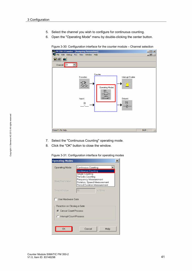
5. Select the channel you wish to configure for continuous counting. 6. Open the "Operating Mode" menu by double-clicking the center button.
Figure 3-30: Configuration interface for the counter module – Channel selection
7. Select the "Continuous Counting" operating mode. 8. Click the "OK" button to close the window.
Figure 3-31: Configuration interface for operating modes

3 Configuration
Counter Module SIMATIC FM 350-2 V1.0, Item ID: 83146298 42
Cop
yrig
ht
Sie
men
s A
G 2
013
All
right
s re
serv
ed
9. Save the changes to the configuration of the FM 350-2 counter module and close the window. Figure 3-32: Configuration interface for the 350-2 counter module
10. Save and compile the HW Config.
Figure 3-33: HW Config
11. Close the HW Config. 12. Open the CFC chart with the driver block. 13. Set the SwGateEn input to TRUE to activate the channel.

3 Configuration
Counter Module SIMATIC FM 350-2 V1.0, Item ID: 83146298 43
Cop
yrig
ht
Sie
men
s A
G 2
013
All
right
s re
serv
ed
Figure 3-34: "Pcs7Cnt1" driver block
NOTICE In order to use the gate function, both the software gate (channel driver) and the hardware gate (digital input of the module) must be activated.
Result You have configured an FM 350-2 counter module channel for continuous counting. The signals at the counter module will be processed in the channel. You can monitor the counter reading on the driver module at the PV1 output.
3 Configuration
Counter Module SIMATIC FM 350-2 V1.0, Item ID: 83146298 44
Cop
yrig
ht
Sie
men
s A
G 2
013
All
right
s re
serv
ed
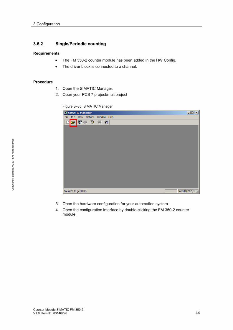
3.6.2 Single/Periodic counting
Requirements The FM 350-2 counter module has been added in the HW Config. The driver block is connected to a channel.
Procedure 1. Open the SIMATIC Manager. 2. Open your PCS 7 project/multiproject
Figure 3–35: SIMATIC Manager
3. Open the hardware configuration for your automation system. 4. Open the configuration interface by double-clicking the FM 350-2 counter
module.

3 Configuration
Counter Module SIMATIC FM 350-2 V1.0, Item ID: 83146298 45
Cop
yrig
ht
Sie
men
s A
G 2
013
All
right
s re
serv
ed
5. Select the channel you wish to configure. 6. Open the "Operating Mode" menu by double-clicking the center button.
Figure 3–36: Configuration interface for the FM 350-2 counter module
7. Select "Single Counting" or "Periodic Counting."
3 Configuration
Counter Module SIMATIC FM 350-2 V1.0, Item ID: 83146298 46
Cop
yrig
ht
Sie
men
s A
G 2
013
All
right
s re
serv
ed
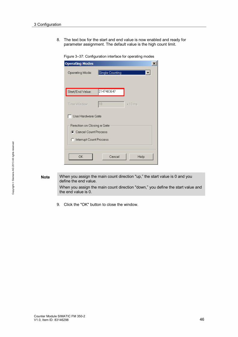
8. The text box for the start and end value is now enabled and ready for parameter assignment. The default value is the high count limit. Figure 3–37: Configuration interface for operating modes
Note When you assign the main count direction "up,” the start value is 0 and you define the end value. When you assign the main count direction "down,” you define the start value and the end value is 0.
9. Click the "OK" button to close the window.

3 Configuration
Counter Module SIMATIC FM 350-2 V1.0, Item ID: 83146298 47
Cop
yrig
ht
Sie
men
s A
G 2
013
All
right
s re
serv
ed
10. Save the changes to the configuration of the FM 350-2 counter module and close the window. Figure 3–38: Configuration interface for the 350-2 counter module
11. Save and compile the HW Config. 12. Load your configuration to your automation system.
Figure 3–39: HW Config
3 Configuration
Counter Module SIMATIC FM 350-2 V1.0, Item ID: 83146298 48
Cop
yrig
ht
Sie
men
s A
G 2
013
All
right
s re
serv
ed
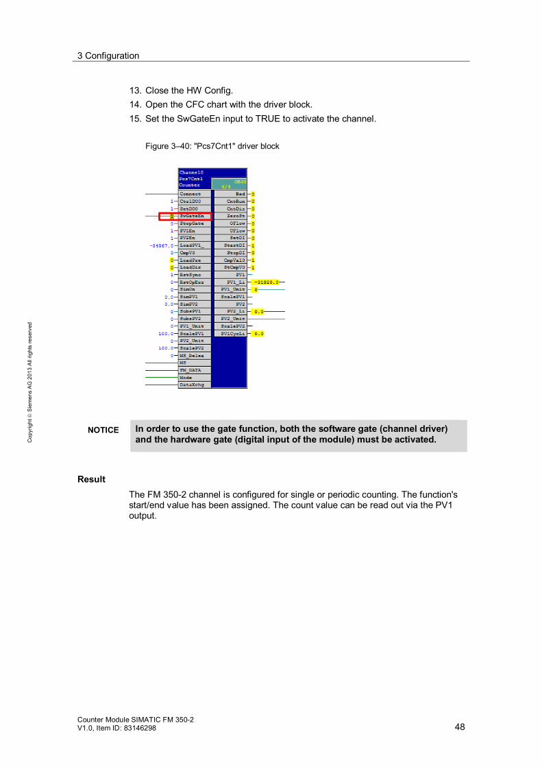
13. Close the HW Config. 14. Open the CFC chart with the driver block. 15. Set the SwGateEn input to TRUE to activate the channel.
Figure 3–40: "Pcs7Cnt1" driver block
NOTICE In order to use the gate function, both the software gate (channel driver) and the hardware gate (digital input of the module) must be activated.
Result The FM 350-2 channel is configured for single or periodic counting. The function's start/end value has been assigned. The count value can be read out via the PV1 output.

3 Configuration
Counter Module SIMATIC FM 350-2 V1.0, Item ID: 83146298 49
Cop
yrig
ht
Sie
men
s A
G 2
013
All
right
s re
serv
ed
3.6.3 Measurements
Requirements The FM 350-2 counter module has been added in the HW Config. The driver block is connected to a channel.
Procedure 1. Open the SIMATIC Manager. 2. Open your PCS 7 project/multiproject
Figure 3–41: SIMATIC Manager
3. Open the hardware configuration for your automation system. 4. Open the configuration interface by double-clicking the FM 350-2 counter
module.

3 Configuration
Counter Module SIMATIC FM 350-2 V1.0, Item ID: 83146298 50
Cop
yrig
ht
Sie
men
s A
G 2
013
All
right
s re
serv
ed
5. Select the channel you wish to configure. 6. Open the "Operating Mode" menu by double-clicking the center button.
Figure 3–42: Configuration interface for the 350-2 counter module
7. Select one of the channel's three measurement functions.
3 Configuration
Counter Module SIMATIC FM 350-2 V1.0, Item ID: 83146298 51
Cop
yrig
ht
Sie
men
s A
G 2
013
All
right
s re
serv
ed
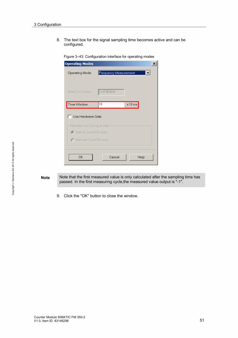
8. The text box for the signal sampling time becomes active and can be configured. Figure 3–43: Configuration interface for operating modes
Note Note that the first measured value is only calculated after the sampling time has passed. In the first measuring cycle,the measured value output is "-1".
9. Click the "OK" button to close the window.

3 Configuration
Counter Module SIMATIC FM 350-2 V1.0, Item ID: 83146298 52
Cop
yrig
ht
Sie
men
s A
G 2
013
All
right
s re
serv
ed
10. Save the changes to the configuration of the FM 350-2 counter module and close the window. Figure 3–44: Configuration interface for the 350-2 counter module
11. Save and compile the HW Config. 12. Load your configuration to your automation system.
Figure 3–45: HW Config
3 Configuration
Counter Module SIMATIC FM 350-2 V1.0, Item ID: 83146298 53
Cop
yrig
ht
Sie
men
s A
G 2
013
All
right
s re
serv
ed
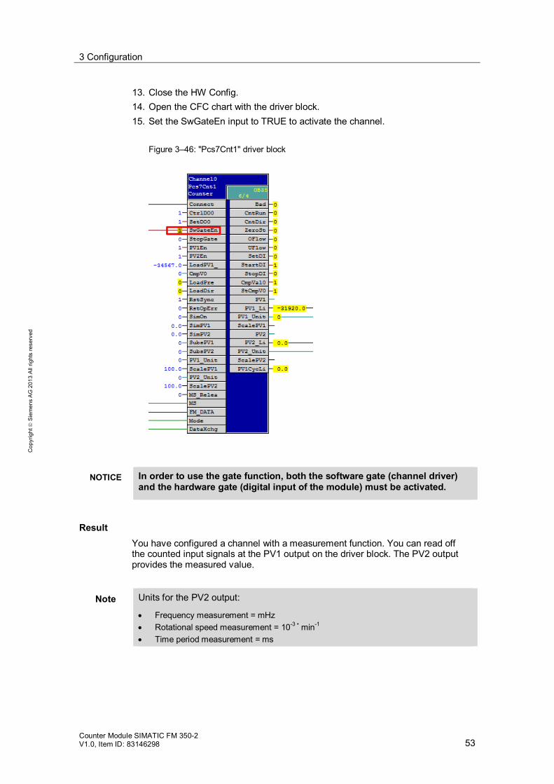
13. Close the HW Config. 14. Open the CFC chart with the driver block. 15. Set the SwGateEn input to TRUE to activate the channel.
Figure 3–46: "Pcs7Cnt1" driver block
NOTICE In order to use the gate function, both the software gate (channel driver) and the hardware gate (digital input of the module) must be activated.
Result You have configured a channel with a measurement function. You can read off the counted input signals at the PV1 output on the driver block. The PV2 output provides the measured value.
Note Units for the PV2 output:
Frequency measurement = mHz Rotational speed measurement = 10-3 • min-1 Time period measurement = ms
3 Configuration
Counter Module SIMATIC FM 350-2 V1.0, Item ID: 83146298 54
Cop
yrig
ht
Sie
men
s A
G 2
013
All
right
s re
serv
ed
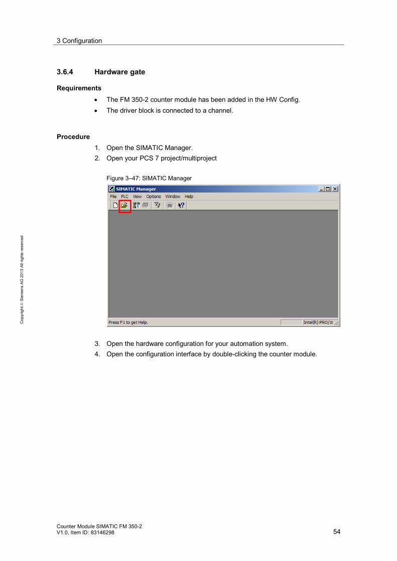
3.6.4 Hardware gate
Requirements The FM 350-2 counter module has been added in the HW Config. The driver block is connected to a channel.
Procedure 1. Open the SIMATIC Manager. 2. Open your PCS 7 project/multiproject
Figure 3–47: SIMATIC Manager
3. Open the hardware configuration for your automation system. 4. Open the configuration interface by double-clicking the counter module.

3 Configuration
Counter Module SIMATIC FM 350-2 V1.0, Item ID: 83146298 55
Cop
yrig
ht
Sie
men
s A
G 2
013
All
right
s re
serv
ed
5. Select the channel you wish to configure. 6. Open the "Operating Mode" menu by double-clicking the center button.
Figure 3–48: Configuration interface for the 350-2 counter module
7. Select the "Use Hardware Gate" check box. Figure 3–49: Configuration interface for operating modes
3 Configuration
Counter Module SIMATIC FM 350-2 V1.0, Item ID: 83146298 56
Cop
yrig
ht
Sie
men
s A
G 2
013
All
right
s re
serv
ed
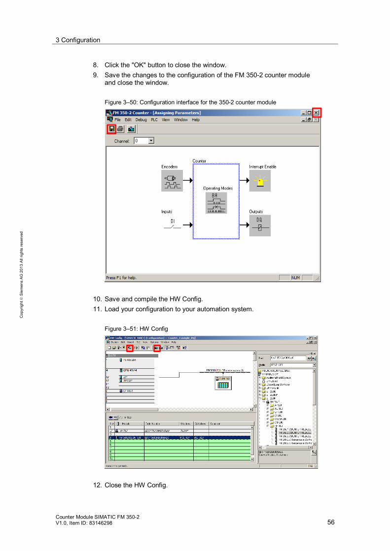
8. Click the "OK" button to close the window. 9. Save the changes to the configuration of the FM 350-2 counter module
and close the window. Figure 3–50: Configuration interface for the 350-2 counter module
10. Save and compile the HW Config. 11. Load your configuration to your automation system.
Figure 3–51: HW Config
12. Close the HW Config.

3 Configuration
Counter Module SIMATIC FM 350-2 V1.0, Item ID: 83146298 57
Cop
yrig
ht
Sie
men
s A
G 2
013
All
right
s re
serv
ed
Result You have activated the channel's hardware gate. Now, the channel will only be activated if the software and hardware gates are active.

3 Configuration
Counter Module SIMATIC FM 350-2 V1.0, Item ID: 83146298 58
Cop
yrig
ht
Sie
men
s A
G 2
013
All
right
s re
serv
ed
3.6.5 Canceling or interrupting the counting function
Requirements The FM 350-2 counter module has been added in the HW Config. The driver block is connected to a channel. You have configured one of the counting functions on the channel.
Procedure 1. Open the SIMATIC Manager. 2. Open your PCS 7 project/multiproject
Figure 3–52: SIMATIC Manager
3. Open the hardware configuration for your automation system. 4. Open the configuration interface by double-clicking the FM 350-2 counter
module.

3 Configuration
Counter Module SIMATIC FM 350-2 V1.0, Item ID: 83146298 59
Cop
yrig
ht
Sie
men
s A
G 2
013
All
right
s re
serv
ed
5. Select the channel you wish to configure. 6. Open the "Operating Mode" menu by double-clicking the center button.
Figure 3–53: Configuration interface for the 350-2 counter module
7. Select interrupt or cancel for a reset of the internal gate. Figure 3–54: Configuration interface for operating modes

3 Configuration
Counter Module SIMATIC FM 350-2 V1.0, Item ID: 83146298 60
Cop
yrig
ht
Sie
men
s A
G 2
013
All
right
s re
serv
ed
8. Click the "OK" button to close the window. 9. Save the changes to the configuration of the FM 350-2 counter module
and close the window. Figure 3–55: Configuration interface for the 350-2 counter module
10. Save and compile the HW Config. 11. Load your configuration to your automation system.
Figure 3–56: HW Config
12. Close the HW Config.
3 Configuration
Counter Module SIMATIC FM 350-2 V1.0, Item ID: 83146298 61
Cop
yrig
ht
Sie
men
s A
G 2
013
All
right
s re
serv
ed
Result You have configured the behavior of the counter channel. When the internal gate is set again, the current value will continue to be used or the start value will be reloaded, depending on your configuration.
Note An overview of the behavior of the counter module channels can be found in chapter 2.3.2.
3 Configuration
Counter Module SIMATIC FM 350-2 V1.0, Item ID: 83146298 62
Cop
yrig
ht
Sie
men
s A
G 2
013
All
right
s re
serv
ed
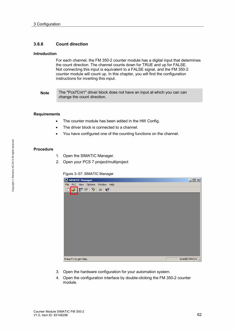
3.6.6 Count direction
Introduction For each channel, the FM 350-2 counter module has a digital input that determines the count direction. The channel counts down for TRUE and up for FALSE. Not connecting this input is equivalent to a FALSE signal, and the FM 350-2 counter module will count up. In this chapter, you will find the configuration instructions for inverting this input.
Note The "Pcs7Cnt1" driver block does not have an input at which you can can change the count direction.
Requirements The counter module has been added in the HW Config. The driver block is connected to a channel. You have configured one of the counting functions on the channel.
Procedure 1. Open the SIMATIC Manager. 2. Open your PCS 7 project/multiproject
Figure 3–57: SIMATIC Manager
3. Open the hardware configuration for your automation system. 4. Open the configuration interface by double-clicking the FM 350-2 counter
module.

3 Configuration
Counter Module SIMATIC FM 350-2 V1.0, Item ID: 83146298 63
Cop
yrig
ht
Sie
men
s A
G 2
013
All
right
s re
serv
ed
5. Select the channel you wish to configure. 6. Open the "Encoders" menu by double-clicking top left button.
Figure 3–58: Configuration interface for the 350-2 counter module
7. Select the "Inverted Direction" check box.
Figure 3–59: Configuration interface for encoders

3 Configuration
Counter Module SIMATIC FM 350-2 V1.0, Item ID: 83146298 64
Cop
yrig
ht
Sie
men
s A
G 2
013
All
right
s re
serv
ed
8. Click the "OK" button to close the window. 9. Save the changes to the configuration of the FM 350-2 counter module
and close the window. Figure 3–60: Configuration interface for the 350-2 counter module
10. Save and compile the HW Config. 11. Load your configuration to your automation system.
Figure 3–61: HW Config
12. Close the HW Config.
3 Configuration
Counter Module SIMATIC FM 350-2 V1.0, Item ID: 83146298 65
Cop
yrig
ht
Sie
men
s A
G 2
013
All
right
s re
serv
ed
Result You have negated the channel's direction input. The channel counts down for FALSE and up for TRUE.

3 Configuration
Counter Module SIMATIC FM 350-2 V1.0, Item ID: 83146298 66
Cop
yrig
ht
Sie
men
s A
G 2
013
All
right
s re
serv
ed
3.6.7 Loading values
Requirements The counter module has been added in the HW Config. The driver block is connected to a channel. You have configured one of the counting functions on the channel.
Note If one of the three measurement modes has been configured, then it is not possible to load values.
Procedure 1. Open the CFC chart with the "Pcs7Cnt1" driver block. 2. Enter the desired value at the "LoadPV1_" input.
Note If the value exceeds the assigned counter limit, then the value is changed to the negative or positive value. An overview of the channel counter limits can be found in chapter 2.4.
Figure 3–62: "Pcs7Cnt1" driver block
3. When a positive edge is received at the "LoadDir" connection, the entered
value is used as the current counter reading.
3 Configuration
Counter Module SIMATIC FM 350-2 V1.0, Item ID: 83146298 67
Cop
yrig
ht
Sie
men
s A
G 2
013
All
right
s re
serv
ed
Result You have entered your load value at the corresponding input. Whenever you send a positive edge to the "LoadDir" input, the current counter reading will be overwritten by the load value. Counting resumes starting at this value in your counter channel configuration.

3 Configuration
Counter Module SIMATIC FM 350-2 V1.0, Item ID: 83146298 68
Cop
yrig
ht
Sie
men
s A
G 2
013
All
right
s re
serv
ed
3.6.8 Comparing the counter reading with a value
Requirements The counter module has been added in the HW Config. The driver block is connected to a channel. You have configured one of the counting functions on the channel.
Note If one of the three measurement modes has been configured, then it is not possible to load values.
Procedure 1. Open the SIMATIC Manager. 2. Open your PCS 7 project/multiproject
Figure 3–63: SIMATIC Manager
3. Open the hardware configuration for your automation system. 4. Open the configuration interface by double-clicking the FM 350-2 counter
module.

3 Configuration
Counter Module SIMATIC FM 350-2 V1.0, Item ID: 83146298 69
Cop
yrig
ht
Sie
men
s A
G 2
013
All
right
s re
serv
ed
5. Select the channel you wish to configure. 6. Open the "Outputs" menu by double-clicking the bottom right button.
Figure 3–64: Configuration interface for the 350-2 counter module
7. Select the comparison type. Figure 3–65: Configuration interface – Outputs

3 Configuration
Counter Module SIMATIC FM 350-2 V1.0, Item ID: 83146298 70
Cop
yrig
ht
Sie
men
s A
G 2
013
All
right
s re
serv
ed
8. Click the "OK" button to close the window. 9. Save the changes to the configuration of the FM 350-2 counter module
and close the window. Figure 3–66: Configuration interface for the 350-2 counter module
10. Save and compile the HW Config. 11. Load your configuration to your automation system.
Figure 3–67: HW Config

3 Configuration
Counter Module SIMATIC FM 350-2 V1.0, Item ID: 83146298 71
Cop
yrig
ht
Sie
men
s A
G 2
013
All
right
s re
serv
ed
12. Close the HW Config. 13. Open the CFC chart with the "Pcs7Cnt1" driver block. 14. Enter a comparison value at the "CmpV0" input.
Figure 3–68: "Pcs7Cnt1" driver block
Result You have assigned the comparison parameter for the channel's output. The output provides a TRUE if the comparison is true. Otherwise, the output provides a FALSE. You can monitor this on the driver block at the "CmpVal0" output.
Note If you haven not assigned a comparison parameter for the output, the output will be permanently set to TRUE.

3 Configuration
Counter Module SIMATIC FM 350-2 V1.0, Item ID: 83146298 72
Cop
yrig
ht
Sie
men
s A
G 2
013
All
right
s re
serv
ed
3.6.9 Extending the counter limits
Note This chapter refers to the extension of the counting range of channel 0 and channel 2. For more information, please see chapter 2.4 of this document.
Requirements The counter module has been added in the HW Config. For the counter limit extension of channel 0, channel 1 must be unassigned. For the counter limit extension of channel 2, channel 3 must be unassigned.
Procedure 1. Open the SIMATIC Manager. 2. Open your PCS 7 project/multiproject
Figure 3–69: SIMATIC Manager
3. Open the hardware configuration for your automation system. 4. Open the configuration interface by double-clicking the FM 350-2 counter
module.
3 Configuration
Counter Module SIMATIC FM 350-2 V1.0, Item ID: 83146298 73
Cop
yrig
ht
Sie
men
s A
G 2
013
All
right
s re
serv
ed
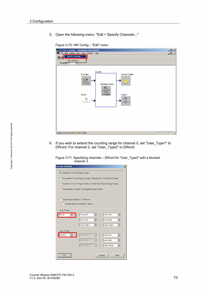
5. Open the following menu: "Edit > Specify Channels..." Figure 3-70: HW Config – "Edit" menu
6. If you wish to extend the counting range for channel 0, set "User_Type1" to DWord. For channel 2, set "User_Type2" to DWord. Figure 3-71: Specifying channels – DWord for "User_Type2" with a blocked
channel 3.
3 Configuration
Counter Module SIMATIC FM 350-2 V1.0, Item ID: 83146298 74
Cop
yrig
ht
Sie
men
s A
G 2
013
All
right
s re
serv
ed
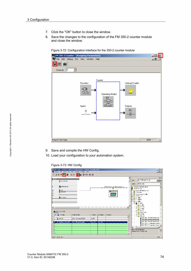
7. Click the "OK" button to close the window. 8. Save the changes to the configuration of the FM 350-2 counter module
and close the window. Figure 3-72: Configuration interface for the 350-2 counter module
9. Save and compile the HW Config. 10. Load your configuration to your automation system.
Figure 3-73: HW Config

3 Configuration
Counter Module SIMATIC FM 350-2 V1.0, Item ID: 83146298 75
Cop
yrig
ht
Sie
men
s A
G 2
013
All
right
s re
serv
ed
11. Close the HW Config. 12. Open the component view of your project. 13. Select the S7 program of your automation system in the project navigation
pane. Figure 3-74: Symbol table in the component view
14. Open the symbol table by double-clicking on the icon. 15. Change the input words (EW) of the channels on which you extended the
counting range into input double word (ED). Accordingly, delete the EW of the blocked channel, e. . if you have extended the counting range of channel 0 (EW520). Change EW520 to ED520 and delete EW522.
16. Save the symbol table and close the symbol editor. 17. Open the CFC chart with the driver block.
3 Configuration
Counter Module SIMATIC FM 350-2 V1.0, Item ID: 83146298 76
Cop
yrig
ht
Sie
men
s A
G 2
013
All
right
s re
serv
ed
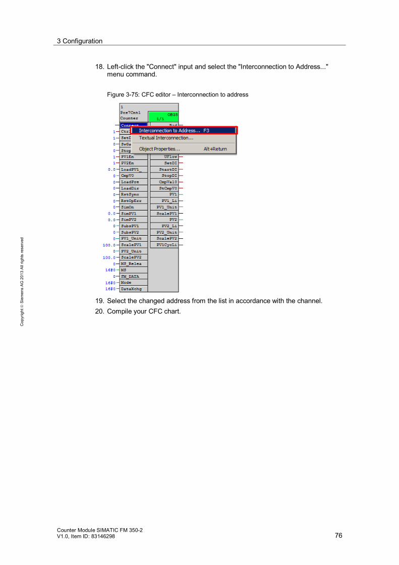
18. Left-click the "Connect" input and select the "Interconnection to Address..." menu command.
Figure 3-75: CFC editor – Interconnection to address
19. Select the changed address from the list in accordance with the channel. 20. Compile your CFC chart.

3 Configuration
Counter Module SIMATIC FM 350-2 V1.0, Item ID: 83146298 77
Cop
yrig
ht
Sie
men
s A
G 2
013
All
right
s re
serv
ed
Note If you do not delete the necessary EW, or if it is still interconnected with a channel driver, then the CFC compiler will generate an error during compilation.
21. Once the compilation has been successfully completed, load the CFC chart to
your automation system.
Figure 3-76: CFC editor – Compiling and loading
3 Configuration
Counter Module SIMATIC FM 350-2 V1.0, Item ID: 83146298 78
Cop
yrig
ht
Sie
men
s A
G 2
013
All
right
s re
serv
ed
Result You have switched the counting range from Word to DWord. You have extended the data area of the driver block in the symbol table. You have connected the new, larger data area to the driver block. A larger data area is now available to the channel for counting.

4 Related literature
Counter Module SIMATIC FM 350-2 V1.0, Item ID: 83146298 79
Cop
yrig
ht
Sie
men
s A
G 2
013
All
right
s re
serv
ed
4 Related literature Table 4-1
Subject area Title \1\ Reference to the
article http://support.automation.siemens.com/WW/view/en/83146298
\2\ SIMATIC PCS 7 overview (collection of links for FAQ, manuals, compendium, forum, application examples and multimedia)
http://support.automation.siemens.com/WW/view/en/63481413
\3\ Manual FM 350-2 Counter module
http://support.automation.siemens.com/WW/view/en/1105178
\4\ FM Configuration Package
http://support.automation.siemens.com/WW/view/en/60237759
5 History Table 5-1
Version Date Modifications
V1.0 12/2013 First edition