Embed Size (px)
Citation preview
SIMATIC NET
DP Base Programming Interfacefor CP 5613/CP 5614
Manual
Preface, Contents
Basic Steps in Creating a DPApplication 1
Overview of PROFIBUS DP 2
Overview of the DP BaseInterface 3
Description of the DPFunctions, Data, and ErrorCodes 4
FAQ (Frequently AskedQuestions)
5
Where to Get Help,Index, Glossary
C79000-G8976-C108-01
Release 1 1999

Copyright Siemens AG, 1999, All rights reservedThe reproduction, transmission or use of this document or itscontents is not permitted without express written authority.Offenders will be liable for damages. All rights, including rightscreated by patent grant or registration of a utility or design, arereserved.
DisclaimerWe have checked the contents of this manual for agreement withthe hardware and software described. Since deviations cannot beprecluded entirely, we cannot guarantee full agreement. However,the data in this manual are reviewed regularly and any necessarycorrections included in subsequent editions. Suggestions forimprovement are welcome.
Siemens AGBereich Automatisierungs- und AntriebstechnikPostfach 48 48, D-90327 Nürnberg
C79000-G8976-C108-01© Siemens AG 1999Technical data subject to change.
Siemens Aktiengesellschaft Printed in the Federal Republic of Germany
Safety Guidelines
This manual contains notices which you should observe to ensure your own personal safety, as well as toprotect the product and connected equipment. These notices are highlighted in the manual by a warningtriangle and are marked as follows according to the level of danger:
! Dangerindicates that death, severe personal injury or substantial property damage will result if proper precautionsare not taken.
! Warningindicates that death, severe personal injury or substantial property damage can result if proper precautionsare not taken.
! Cautionindicates that minor personal injury or property damage can result if proper precautions are not taken.
Notedraws your attention to particularly important information on the product, handling the product, or to aparticular part of the documentation.
Qualified Personnel
Only qualified personnel should be allowed to install and work on this equipment . Qualified persons aredefined as persons who are authorized to commission, to ground, and to tag circuits, equipment, andsystems in accordance with established safety practices and standards.
Correct Usage
Note the following:
! WarningThis device and its components may only be used for the applications described in the catalog or thetechnical description, and only in connection with devices or components from other manufacturers whichhave been approved or recommended by Siemens.
This product can only function correctly and safely if it is transported, stored, set up, and installed correctly,and operated and maintained as recommended.
Trademarks
SIMATIC® and SIMATIC NET® are registered trademarks of Siemens AG.
Third parties using for their own purposes any other names in this document which refer to trademarksmight infringe upon the rights of the trademark owners.

DP Base Programming Interface for CP 5613/CP 5614C79000-G8976-C108-01 3
Preface
Purpose of the Manual
This manual supports you when creating user programs for the DP programminginterface of the CP 5613/CP 5614.
It is assumed that you are familiar with writing user programs in the "C"programming language in Windows NT.
Validity of the Manual
This manual applies to the following software versions:
x CP 5613/CP 5614 (DP Base V1.0)
x CP 5613/CP 5614 (DP Base V1.1)
Guide to the Manual
To help you to find specific information quickly, the manual includes the followingparts:
x At the front of the manual you will find a complete table of contents.
x At the back of the manual, you will find a comprehensive index with which youcan find topics quickly.
x After the index, there is also a glossary in which important terminology used inthe manual is defined.

Preface
DP Base Programming Interface for CP 5613/CP 56144 C79000-G8976-C108-01

DP Base Programming Interface for CP 5613/CP 5614C79000-G8976-C108-01 5
Contents
1 Basic Steps in Creating a DP Application ......................................................................9
2 Overview of PROFIBUS DP ...........................................................................................13
2.1 Where Does PROFIBUS DP Fit In? .....................................................................14
2.2 The Master-Slave Concept of PROFIBUS DP......................................................16
2.3 Cyclic Polling by the Master.................................................................................18
2.4 Process Image of the DP Master .........................................................................19
2.5 Startup and Operational Phase of a DP System...................................................21
2.6 Modes of the DP Master ......................................................................................23
2.7 Separation of the Slave Data from the User Program...........................................25
2.8 Reliability of DP...................................................................................................27
2.9 Control Frames to One or More Slaves................................................................28
2.10 Typical Sequences in DP.....................................................................................30
2.11 DP-V1 As an Extension of DP..............................................................................32
2.12 Slave Functionality of the CP 5614 ......................................................................34
3 Overview of the DP Base Interface ...............................................................................37
3.1 Functions and Data .............................................................................................38
3.2 The Importance of Configuration..........................................................................40
3.3 Consistent Access to the process image..............................................................42
3.4 Working with Hardware Events ............................................................................43
3.5 Fast Logic ...........................................................................................................44
3.6 Overview of Triggering and Receiving Events......................................................45
3.7 Typical Sequences ..............................................................................................473.7.1 Initializing and Exiting the Master Mode ...............................................................473.7.2 Typical Sequences in Polling Master Operation ...................................................493.7.3 Typical Sequences for Polling DPC1 master operation.........................................513.7.4 Typical Sequences in Master Operation with Hardware Events............................533.7.5 Typical Sequences in DPC1 Operation with Semaphores ....................................56
3.8 Properties of the CP 5614 (Slave Functions, Transfer Software) ..........................58
3.9 Typical Sequences for the CP 5614 Slave Module...............................................593.9.1 Initialization and Shutdown of the Slave Module in the "Simple" Mode .................593.9.2 Initialization and Shutdown of the Slave Module in the Dynamic" Mode................603.9.3 Typical Sequences with Semaphores on the slave Module ..................................62
3.10 Multiple Protocols, User Programs, CPUs............................................................64

Contents
DP Base Programming Interface for CP 5613/CP 56146 C79000-G8976-C108-01
4 Description of the DP Functions, Data, and Error Codes ............................................65
4.1 List of Functions of the CP 5613 and CP 5614.....................................................664.1.1 Overview of the Functions ...................................................................................684.1.2 DP_start_cp ........................................................................................................704.1.3 DP_reset_cp........................................................................................................714.1.4 DP_open .............................................................................................................724.1.5 DP_get_pointer ...................................................................................................734.1.6 DP_release_pointer.............................................................................................754.1.7 DP_close.............................................................................................................764.1.8 DP_get_err_txt ....................................................................................................784.1.9 DP_set_mode......................................................................................................794.1.10 DP_slv_state .......................................................................................................814.1.11 DP_read_slv_par.................................................................................................834.1.12 DP_global_ctrl .....................................................................................................854.1.13 DP_ds_read ........................................................................................................874.1.14 DP_ds_write........................................................................................................904.1.15 DP_read_alarm ...................................................................................................934.1.16 DP_alarm_ack.....................................................................................................964.1.17 DP_get_actual_cfg ..............................................................................................994.1.18 DP_enable_event..............................................................................................1024.1.19 DP_disable_event .............................................................................................1074.1.20 DP_get_result....................................................................................................1084.1.21 DP_get_cref ......................................................................................................1114.1.22 DP_init_sema_object.........................................................................................1124.1.23 DP_delete_sema_object....................................................................................1144.1.24 DP_fast_logic_on ..............................................................................................1154.1.25 DP_fast_logic_off ..............................................................................................116
4.2 Additional Functions of the CP 5614 ..................................................................1174.2.1 Overview of the Slave Module Functions ...........................................................1184.2.2 DPS_open.........................................................................................................1204.2.3 DPS_close ........................................................................................................1244.2.4 DPS_start..........................................................................................................1254.2.5 DPS_stop..........................................................................................................1264.2.6 DPS_get_baud_rate ..........................................................................................1274.2.7 DPS_get_gc_command.....................................................................................1294.2.8 DPS_get_state ..................................................................................................1314.2.9 DPS_set_diag ...................................................................................................1334.2.10 DPS_get_ind .....................................................................................................1354.2.11 DPS_set_resp ...................................................................................................1404.2.12 DPS_calc_io_data_len ......................................................................................142
4.3 Access to the Process Image of the CP 5613/CP 5614......................................1434.3.1 Reading the Input Data of a DP Slave................................................................1444.3.2 Reading the Diagnostic Data of a DP Slave .......................................................1464.3.3 Writing the Output Data of a DP Slave...............................................................1484.3.4 Checking the Slaves for Changed Data .............................................................1504.3.5 Querying the State of a DP Slave ......................................................................1524.3.6 Querying Information about the DP Master ........................................................1544.3.7 Querying Current Bus Parameters of the Master................................................1554.3.8 Querying Information about DP Slaves ..............................................................1584.3.9 Reading PROFIBUS Statistical Data..................................................................1594.3.10 Querying the Fast Logic Status..........................................................................1614.3.11 Activating/Deactivating the Generation of Hardware Events...............................1624.3.12 Sending Data with the CP 5614 as DP Slave.....................................................164

Contents
DP Base Programming Interface for CP 5613/CP 5614C79000-G8976-C108-01 7
4.3.13 Receiving Data with the CP 5614 as DP Slave ..................................................1654.3.14 Sending Diagnostic Data with the CP 5614 as DP Slave....................................166
4.4 Error Codes.......................................................................................................1674.4.1 Entries in the error_decode, error_code_1 and error_code_2 Structure
Elements ...........................................................................................................171
4.5 Formats of the Slave Data .................................................................................175
4.6 Formats of the Slave Diagnostic Data................................................................1764.6.1 Overview of the Entire Structure ........................................................................1774.6.2 Format of the Diagnostic Data Header ...............................................................1784.6.3 Format of the Device-Related Diagnostic Data (Standard DP Slave)..................1824.6.4 Format of the Device-Related Diagnostic Data (Slaves with DP-V1
Extensions) .......................................................................................................1834.6.5 Format of ID-Related Diagnostics ......................................................................1884.6.6 Format of Channel-Related Diagnostics.............................................................189
4.7 Format of the Slave Parameter Data..................................................................1934.7.1 Structure of the General Slave Parameters........................................................1944.7.2 Structure of the Parameter Assignment Data .....................................................1974.7.3 Structure of the Configuration Data....................................................................202
5 FAQ (Frequently Asked Questions) ............................................................................205
5.1 FAQs about the Range of Functions of the Product ...........................................206
5.2 FAQs about Structuring the User Program.........................................................208
5.3 FAQ Check List for Programmers ......................................................................211
5.4 FAQs about Debugging and Starting Up Your Program......................................214
5.5 FAQs Miscellaneous Programming Questions ...................................................215
6 Where to Get Help ........................................................................................................217
6.1 Help with Technical Questions...........................................................................218
6.2 Contacts for training with SIMATIC NET ............................................................221
7 Index......................................................................................................................... ....223
8 Glossary .......................................................................................................................227

Contents
DP Base Programming Interface for CP 5613/CP 56148 C79000-G8976-C108-01

DP Base Programming Interface for CP 5613/CP 5614C79000-G8976-C108-01 9
Basic Steps in Creating a DP Application
1This chapter recommends a step-by-step procedure for creating a DP userprogram based on the DP programming interface of the CP 5613 and CP 5614known as "DP Base". The steps begin with the basics of PROFIBUS DP and arecompleted when you test your application.
The DP Base programming interface allows direct access to the DP process imagein the dual-port RAM of the module. The DP Base programming interface istherefore not compatible with the DP programming interface of the CP 5412 (A2),the CP 5511, and the CP 5611.

Basic Steps in Creating a DP Application
DP Base Programming Interface for CP 5613/CP 561410 C79000-G8976-C108-01
Procedure
The steps outlined below represent the fastest and simplest way of achieving youraims:
Step Description
1 Familiarize yourself with the basic principles of PROFIBUS DP. Readthe following chapter 2 (“Overview of PROFIBUS DP").
2 Familiarize yourself with the basic characteristics of the DP Baseprogramming interface of the CP 5613 and CP 5614. Read thefollowing chapter 3 (“Overview of the DP Base Interface").
3 Check through the contents of the subfolder "prog" in your installationfolder so that you know what it contains and the purpose of thecomponents for the subsequent steps.
The subfolder contains the following:� The "readme.txt" file with the latest additional information and most
recent modifications.� The C header file "dp_5613.h" with the functions and data structures
of the DP Base interface and "5613_ret.h" with the return codes.� The import libraries "dp_base.lib" and "dps_base.lib" for linking to
your user program.� The sample programs and corresponding databases in the
"examples" subfolder.
4 Now work through the source text of the sample program "ExamEasy"and read through the functions and data accesses in Chapter 4Description of the DP Functions, Data, and Error Codes
5 Adapt the "ExamEasy" sample program to suit your systemconfiguration by, for example, using additional or different slaves.Compile and link the sample program and try it out. You may need toextend the "ExamEasy" sample database (with COM PROFIBUS).
6 Now work through the source text of the sample program "ExamComp",modify the program and try it out with an extended sample database.
7 If you want to use the slave functions of the CP 5614, you should alsowork through the "transfer" sample, modify it to your requirements andtry it out with an extended sample database.
8 Please read the FAQs in Chapter 5, particularly the check list forprogrammers and the information on structuring your user program.
Table continued on next page

Basic Steps in Creating a DP Application
DP Base Programming Interface for CP 5613/CP 5614C79000-G8976-C108-01 11
Table continued from previous page
Step Description
9 Now create your own DP user program. You can use the "ExamComp"sample as a basis.
10 Test your application. Refer to the information and tips in the FAQ list inChapter 5 and the diagnostic tools described in the installationinstructions.

Basic Steps in Creating a DP Application
DP Base Programming Interface for CP 5613/CP 561412 C79000-G8976-C108-01
DP Base Programming Interface for CP 5613/CP 5614C79000-G8976-C108-01 13
Overview of PROFIBUS DP
2This chapter will familiarize you with the basic principles of PROFIBUS DP.

Overview of PROFIBUS DP
DP Base Programming Interface for CP 5613/CP 561414 C79000-G8976-C108-01
2.1 Where Does PROFIBUS DP Fit In?
PROFIBUS - The Worldwide Fieldbus Strategy
The trend towards reducing costs in automation engineering has meant thatprogrammable controllers (PLCs), PCs, drives, transducers and sensors are beingnetworked more and more. This has resulted in greater distribution of these fielddevices using a fieldbus as the common communications medium for exchanginginformation.
The demand for an open, heterogeneous fieldbus system representing a safe andlong-term investment for the user has been met by PROFIBUS. PROFIBUS is abus system for communication between programmable controllers or PCs and fielddevices based on the European standard EN 50 170, Volume 2. This means thatboth users and manufacturers can be certain about long-term investments andguarantees "openness" for all applications conforming with the standard worldwide.
With more than 2 million network nodes in over 200,000 applications, PROFIBUSis the most successful open fieldbus having proved itself in applications inproduction automation, process automation, drive engineering, and buildingautomation.
The PROFIBUS users organization represents a widespread information forum forPROFIBUS manufacturers and users. This is an organization involving more than800 users, manufacturers and advisers from more than 20 countries worldwide. Asa result of this cooperation, more than 1600 products are now available for use inPROFIBUS systems.
Siemens has supported PROFIBUS for many years as an optimized fieldbussolution and reliable investment for the user and supplies both products andcomplete systems. Apart from the programmable controllers (PLCs), devices suchas network components, PC communications processors, and field devices forPROFIBUS are also included in the wide range of products.
The Role of the PC in PROFIBUS
Apart from the trend towards distribution, the standard PC is also becoming moreimportant as an automation tool particularly in control tasks and for plantvisualization thanks to its increased performance and widespread availability.

Overview of PROFIBUS DP
DP Base Programming Interface for CP 5613/CP 5614C79000-G8976-C108-01 15
The Advantages of DP
PROFIBUS DP is intended for fast data exchange in the fieldbus area.
Distributed peripheral devices collect the input signals locally and transfer them viathe fieldbus to the central controller in the PG/PC. In the opposite direction, thecentral controller sends the output data to the distributed peripheral devices.
The use of PROFIBUS DP means a considerable reduction in cabling compared toprevious direct wiring of components.

Overview of PROFIBUS DP
DP Base Programming Interface for CP 5613/CP 561416 C79000-G8976-C108-01
2.2 The Master-Slave Concept of PROFIBUS DP
Distributed I/Os
The distributed peripheral I/Os (abbreviated to DP in the remainder of this manual)allow a large number of analog and digital input/output modules to be used in adistributed structure in the immediate vicinity of the process.
Node Classes
PROFIBUS DP defines two classes of bus nodes. Slaves as peripheral devices arepassive nodes. Masters (class 1) are active nodes and control the slaves.
DP Master Class 1
Using the CP 5613 or CP 5614, the PC can adopt the role of DP master.Depending on the application, this role can also be adopted by, for example, aSIMATIC S7 programmable logic controller. In the remainder of the manual, the DPmaster class 1 is simply referred to as DP master.
DP Master Class 2
When installing and configuring the DP system or controlling the plant duringoperation, you can also use master class 2 devices.

Overview of PROFIBUS DP
DP Base Programming Interface for CP 5613/CP 5614C79000-G8976-C108-01 17
DP Slave
A DP slave is a peripheral device from which the master reads in input informationand to which it sends output information. There are also devices that provide onlyinput or only output information.
Slaves are generally inexpensive since passive participation on the bus is simple toimplement.
Figure 1 illustrates the basic structure and the components of a PROFIBUS DPsystem controlled by a computer with a PROFIBUS master installed(CP 5613/CP 5614).
DP slaves
DP master withPROFIBUSPC adapterCP 5613
PROFIBUS
Process
Figure 1 Basic Structure of a DP System.

Overview of PROFIBUS DP
DP Base Programming Interface for CP 5613/CP 561418 C79000-G8976-C108-01
2.3 Cyclic Polling by the Master
Polling
Communication between the DP master and the distributed nodes takes the formof polling. Polling means that the DP master sends cyclic calls to its slaves duringthe productive phase. A separate call frame is sent to each DP slave.
In one polling cycle, all the operational DP slaves are addressed. The next pollingcycle starts as soon as the last slave has been addressed. This ensures that thedata is up to date.
DP master
Input data
Output data
DP slaves
Figure 2 Schematic Representation of Polling
Output Data
The call frame contains the current output data that the DP slave will apply to itsoutput ports. The data belonging to this area are specified by the DP application. Ifa DP slave does not have output ports, an "empty frame" is sent to it instead.
Input Data
The reception of a call frame must be confirmed by the DP slave by returning aconfirmation frame. The confirmation frame contains the current input data that areapplied to the input ports of the DP slave. If a DP slave does not have input ports,an "empty frame" is returned instead.

Overview of PROFIBUS DP
DP Base Programming Interface for CP 5613/CP 5614C79000-G8976-C108-01 19
2.4 Process Image of the DP Master
Automatic Updating of the Data
The CP 5613 or 5614 as the PROFIBUS DP master polls the data of the slavescontinuously and buffers this data on the PC. The DP application accesses thisdata directly. This means that the DP application is not involved in polling theslaves.
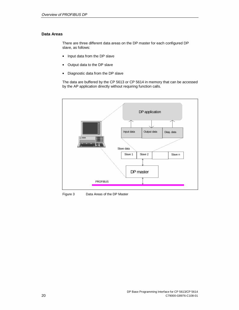
Figure 3 shows an overview of the data areas on the DP master.
Overview of PROFIBUS DP
DP Base Programming Interface for CP 5613/CP 561420 C79000-G8976-C108-01
Data Areas
There are three different data areas on the DP master for each configured DPslave, as follows:
x Input data from the DP slave
x Output data to the DP slave
x Diagnostic data from the DP slave
The data are buffered by the CP 5613 or CP 5614 in memory that can be accessedby the AP application directly without requiring function calls.
Slave data
DP master
Slave nSlave 2Slave 1
DP application
PROFIBUS
Output data Diag. dataInput data
Figure 3 Data Areas of the DP Master

Overview of PROFIBUS DP
DP Base Programming Interface for CP 5613/CP 5614C79000-G8976-C108-01 21
2.5 Startup and Operational Phase of a DP System
Functions of the DP Master during Startup and Operation
The DP master handles the following tasks:
x Initialization of the DP system
x Parameter assignment/configuration of the DP slaves
x Cyclic data transfer to the DP slaves
x Monitoring the DP slaves
x Storage of diagnostic information
Initialization
The DP master can only exchange productive data with the DP slaves when it hasassigned parameters to the slaves and configured them. The parameterassignment/configuration takes place as follows:
x During the startup phase of the DP master
x Following any temporary failure of a DP slave during the productive phase
Parameter Assignment
The parameter assignment frame provides global operating parameters for the DPslave (for example ID).
Configuration
The configuration frame is sent after the DP slave has been assigned parameters.This frame contains the current configuration of the DP slave. The configurationincludes the number and type of input/output ports. The DP slave compares thereceived configuration frame with the values that it determined itself during thestartup phase. If the values match, the DP slave confirms the configuration andchanges to the productive phase.
State of the Slave
During the operational phase, the DP master evaluates the confirmation framesreceived from the DP slaves. Based on this information, the DP master can find outthe current state of the DP slaves.
Overview of PROFIBUS DP
DP Base Programming Interface for CP 5613/CP 561422 C79000-G8976-C108-01
Diagnostics
If a DP slave detects an error/fault during the initialization or productive phase, itcan signal this to the DP master in the form of diagnostic data. The receiveddiagnostic data are entered in the diagnostic area of the DP master. In this case,the DP application is then responsible for reacting to the error.

Overview of PROFIBUS DP
DP Base Programming Interface for CP 5613/CP 5614C79000-G8976-C108-01 23
2.6 Modes of the DP Master
Overview
During communication with the DP slaves, the DP master can adopt the followingfour modes:
x OFFLINE
x STOP
x CLEAR (or AUTOCLEAR)
x OPERATE
Modes
Each of these modes is characterized by defined actions between the DP masterand the DP slaves.
MasterMode
Meaning
OFFLINE No communication between the DP master and DP slaves.This is the startup mode of the DP master.
STOP In this mode, there is also no communication between the DPmaster and the DP slaves. In contrast to the OFFLINE mode, aDP diagnostic station (DP master class 2) can read outdiagnostic information from the DP master.
CLEAR(orAUTOCLEAR)
All the DP slaves entered and activated in the database areassigned parameters and configured in this mode. This isfollowed by the cyclic data exchange between the DP masterand DP slaves. In this CLEAR mode, the value 0 or emptyframes are sent to all slaves with a process output; in otherwords, process output is deactivated. The input data of theslaves are known and can be read out.
OPERATE The cyclic, productive data transfer to the DP slaves takesplace in the OPERATE mode. This is the productive phase. Inthis mode, the DP slaves are addressed one after the other bythe DP master. The call frame transfers the actual output dataand the corresponding response frame transfers the actualinput data.

Overview of PROFIBUS DP
DP Base Programming Interface for CP 5613/CP 561424 C79000-G8976-C108-01
Setting the Operating Mode
When the CP 5613 or CP 5614 is started up, the module runs through the modesOFFLINE -> STOP -> CLEAR -> OPERATE controlled by the user program.

Overview of PROFIBUS DP
DP Base Programming Interface for CP 5613/CP 5614C79000-G8976-C108-01 25
2.7 Separation of the Slave Data from the User Program
The process image is separate from the user program and the slaves.
To increase efficiency, the DP standard does not include flow control. The timing ofthe cyclic updating of the process image of the DP master implementation isconnected neither to the DP slaves nor to the user program. Examples of differentsituations are shown below:
Example: The slave writes too quickly
If, for example, an analog slave modifies its output data quickly (sequence 1.11,1.2, 1.3, 1.42, 1.5, 1.6, 1.7, 1.8, ...), the DP master only receives a sequence of"snapshots" that it enters in the process image (sequence 1.11, 1.3, 1.5, 1.8, ...).
Example: The user program reads too quickly
If the user program polls the process image extremely quickly, it obtains the valuesmore than once since it overtakes the polling cycle of the master. Based on theexample above, the user program then reads a sequence 1.1, 1.1, 1.1, 1.1, 1.3,1.3, 1.3, 1.5, 1.5, 1.5, ...
Example: The user program writes too quickly
If the user program modifies the process image extremely quickly (sequence 1, 2,3, 4, 5, 6, ...), it overtakes the polling cycle of the DP master. This then onlytransfers "snapshots" to the slave (sequence 1, 4, 6, ...).
Example: The user program reads too slowly
If the user program only polls the process image occasionally, for example,because it has various tasks to execute in the meantime, it is possible that somevalues will be skipped. The sequence 1.1, 1.2, 1.3, 1.4 in the process image thenbecomes, for example 1.1, 1.3 etc. in the user program.

Overview of PROFIBUS DP
DP Base Programming Interface for CP 5613/CP 561426 C79000-G8976-C108-01
Remedy
If the user program requires a better link to the slave than described above, thereare a number of options available:
x With the hardware events of the CP 5613 and CP 5614, the user program canbe informed of changes on the slave.
x With the DP protocol expansion DP-V1 master class 1 (DPC1), the userprogram can read and write data with a confirmation and can confirm alarms (ifthis is supported by the slaves).
x With user-specific implementations in the user program and on the slaves, user-specific flow controls can be achieved (packed into the DP process image orDPC1 data) to link the master and slaves and to avoid loss of data.
x The hardware event at the start of the CP 5613/CP 5614 cycle can be used forsynchronization.

Overview of PROFIBUS DP
DP Base Programming Interface for CP 5613/CP 5614C79000-G8976-C108-01 27
2.8 Reliability of DP
Reliability Concept
The DP programming interface provides various mechanisms to limit the effects ofthe failure of a communication connection or the DP master.
x A watchdog function can be configured on the DP slave so that if a slave is notaccessed for a longer period of time it can change automatically to a safe state.
x The AUTOCLEAR function can be activated to ensure that if DP slaves are notaccessible, the master automatically changes to the CLEAR mode.
x A sign-of-life monitoring function can be activated on the DP master thatrecognizes inactivity of a DP user program so that the DP slaves controlled bythe master can be changed to a safe state (for the software version in which thisfunction is available, refer to the version table in Section of the installationinstructions).
The AUTOCLEAR function
The AUTOCLEAR option can be set during configuration. If an error occurs on oneor more DP slaves during the productive phase, the DP master then changesautomatically to the AUTOCLEAR mode (the DP system is closed down). TheAUTOCLEAR mode is the same as the CLEAR mode. The DP master then sendsdata with the value 0 or empty frames in the output direction to the DP slaves. TheDP master can no longer exit this mode automatically; in other words, the changeto the OPERATE mode must be triggered explicitly by the user.

Overview of PROFIBUS DP
DP Base Programming Interface for CP 5613/CP 561428 C79000-G8976-C108-01
2.9 Control Frames to One or More Slaves
Purpose of Control Frames
A control frame is a frame that the master sends to one slave, a group, severalgroups or to all slaves. These frames are not acknowledged by the slaves.
Control frames are used to transfer control commands (known as global controlcommands) to the selected slaves to allow synchronization. A control commandcontains three components:
x Identifier indicating whether one or more DP slaves are being addressed
x Identification of the slave group
x Control command
Creating Groups
During configuration, you can assign a group identifier to a slave; in other words, itis possible to include several slaves in one group.
Which slaves belong to a group is specified when you create the database. Duringthis phase, each DP slave can be assigned a group number. The DP slave isinformed of this group number during the parameter assignment phase. You canspecify a maximum of eight groups.
Overview of PROFIBUS DP
DP Base Programming Interface for CP 5613/CP 5614C79000-G8976-C108-01 29
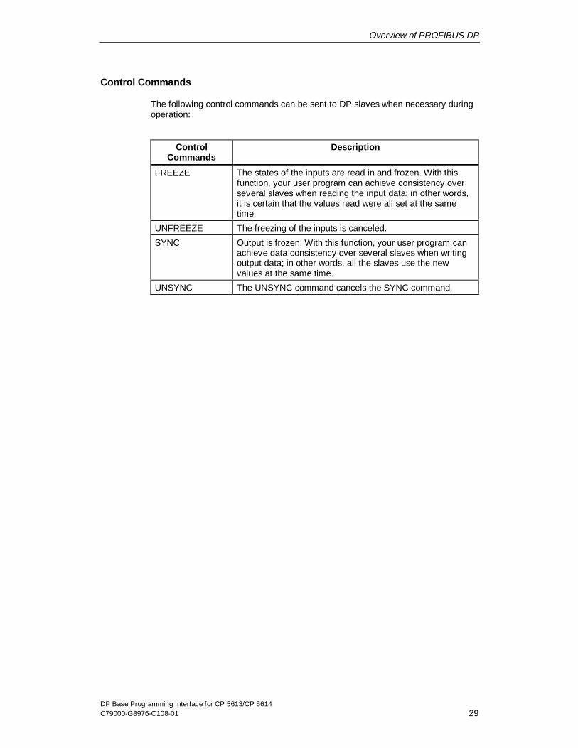
Control Commands
The following control commands can be sent to DP slaves when necessary duringoperation:
ControlCommands
Description
FREEZE The states of the inputs are read in and frozen. With thisfunction, your user program can achieve consistency overseveral slaves when reading the input data; in other words,it is certain that the values read were all set at the sametime.
UNFREEZE The freezing of the inputs is canceled.
SYNC Output is frozen. With this function, your user program canachieve data consistency over several slaves when writingoutput data; in other words, all the slaves use the newvalues at the same time.
UNSYNC The UNSYNC command cancels the SYNC command.

Overview of PROFIBUS DP
DP Base Programming Interface for CP 5613/CP 561430 C79000-G8976-C108-01
2.10 Typical Sequences in DP
Basic Sequence on the DP Master
A typical sequence run by a DP master when triggered by the user program isshown below:
Step Meaning
1 Initial situation: The DP master is in the OFFLINE mode.
2 The DP master changes to the STOP mode.
3 The DP master changes to the CLEAR mode. At this point itautomatically assigns parameters to the slaves and configuresthem and then starts to send cyclic zero frames or empty frames(depending on the configuration).
4 The DP master changes to the OPERATE mode.
5 The output data of the user program are now transferredcyclically to the slaves, the input data are transferred from theslaves to the user program.
6 The master changes to the intermediate modes CLEAR andSTOP and then changes to the final mode OFFLINE and isturned off.
Failure of a Slave
While the DP master is in the CLEAR or OPERATE mode, a slave may fail; in otherwords, no longer respond). The master then automatically attempts to reassignparameters and reconfigure the slave so that it can be included in the cycle again.
Activating/Deactivating Slaves
When the DP master is in the CLEAR or OPERATE mode, slaves can be activatedor deactivated. A deactivated slave is no longer accessed by the master.
AUTOCLEAR
In some circumstances, the DP master can change from the OPERATE to theAUTOCLEAR mode, see Section 2.8.

Overview of PROFIBUS DP
DP Base Programming Interface for CP 5613/CP 5614C79000-G8976-C108-01 31
Receiving Dia gnostic Data
When the slave returns high-priority input data to the master, it indicates that it hasdiagnostic data. The master then fetches the information and makes it available tothe user program.

Overview of PROFIBUS DP
DP Base Programming Interface for CP 5613/CP 561432 C79000-G8976-C108-01
2.11 DP-V1 As an Extension of DP
Overview of the DP Protocol with DP-V1 Extensions
Apart from cyclic DP master operation (see Section 2.3), two further extensions aredefined as DP-V1: DPC1 and DPC2. The paragraphs below contain an overview ofthese extensions:
DPC1 DP DPC2
DP slave with DP-V1additional functions
User program User program
DP/DPC1 prog.interface
DPC2 prog.interface
PG/PCDP master class 1
PG/PCDP master class 2
Acycl. operationMSAC_C2
Cycl.operationMSCY C1
Acycl.operationMSAC_C1
DP-V1 Master Class 1 (DPC1)
With DPC1, a cyclic DP master can also send or read slave data and receive andacknowledge alarms. These data are not process data but slave-specific additionaldata (for example, new parameters). These data are not sent cyclically and mustbe acknowledged explicitly by the slave.

Overview of PROFIBUS DP
DP Base Programming Interface for CP 5613/CP 5614C79000-G8976-C108-01 33
DP-V1 Master Class 2 (DPC2)
An additional DP master that is not operating cyclically can establish connectionsto slaves and send or read slave data using DPC2, for example, to reassignparameters or for diagnostic purposes.
For the software version in which the DPC2 functions are available for theCP 5613/CP 5614, refer to the version table in Section of the InstallationInstructions.

Overview of PROFIBUS DP
DP Base Programming Interface for CP 5613/CP 561434 C79000-G8976-C108-01
2.12 Slave Functionality of the CP 5614
The Slave Functionality (Only CP 5614)
The piggy-back module on the CP 5614 provides slave functionality with its secondPROFIBUS port. The slave is controlled by another DP master.
DP slave
PROFIBUS DP (II)
PROFIBUS DP (I)
RS
485CP 5614
RS
485
Slave
Master
ControllingDP master
Slaveapplication
Masterapplication
PC
DP slave

Overview of PROFIBUS DP
DP Base Programming Interface for CP 5613/CP 5614C79000-G8976-C108-01 35
The Transfer Software (Only CP 5614)
To operate the CP 5614 with master and slave functionality, you can use thesample transfer software. The transfer software transfers data between the masterand slave section of the CP 5614.
The transfer software includes an access with which additional input, output ordiagnostic jobs can be executed. Your user program can use this access to addadditional functions to the transfer program. (In the sample program, a counter onthe CP 5614 slave module is incremented.)
The example illustrates how a separate transfer function can access the processimage of the CP 5614 or CP 5613 with a local application.
PROFIBUS DP (II)
PROFIBUS DP (I)
RS
485CP 5614
RS
485
Slave
Master
Transfersoftware
PC
ControllingDP master
DP slave DP slave
Access
The Configuration for the Transfer Software (Only CP 5614)
To allow you to specify the separate transfer function, a configuration tool and aconfigured transfer file are also shipped as an example.
Using the configuration tool, you can specify how data are copied from master toslave and vice-versa.

Overview of PROFIBUS DP
DP Base Programming Interface for CP 5613/CP 561436 C79000-G8976-C108-01
DP Base Programming Interface for CP 5613/CP 5614C79000-G8976-C108-01 37
Overview of the DP Base Interface
3The programming interface of the CP 5613/CP 5614 is known as the DP Baseinterface. This chapter explains the basic characteristics of the DP Base interfaceincluding typical call and access sequences to prepare you for creating your ownDP applications.
For a detailed description of the function calls and data access, please refer toSection 3.10.
Overview of the DP Base Interface
DP Base Programming Interface for CP 5613/CP 561438 C79000-G8976-C108-01
3.1 Functions and Data
Basic Structure of the DP Base Interface
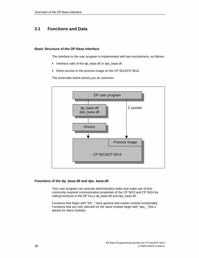
The interface to the user program is implemented with two mechanisms, as follows:
x Interface calls of the dp_base.dll or dps_base.dll
x Direct access to the process image on the CP 5613/CP 5614
The schematic below shows you an overview.
CP 5613/CP 5614
DP user program
Process image
dp_base.dlldps_base.dll
Drivers
C pointer
Functions of the dp_base.dll and dps_base.dll
Your user program can execute administrative tasks and make use of lesscommonly required communication properties of the CP 5613 and CP 5614 bycalling functions in the DP DLLs dp_base.dll and dps_base.dll.
Functions that begin with "DP_" have general and master module functionality.Functions that are only relevant for the slave module begin with "dps_" (the sstands for slave module).

Overview of the DP Base Interface
DP Base Programming Interface for CP 5613/CP 5614C79000-G8976-C108-01 39
Direct Access to the Process Image
While your user program is running, regularly required data from the CP 5613 andCP 5614 are available directly in a memory area of the CP. These include mainlythe input, output, and diagnostic data of the DP slaves but also include mode andconfiguration data. Your user program can access the process image directly usinga C pointer.
Overview of the DP Base Interface
DP Base Programming Interface for CP 5613/CP 561440 C79000-G8976-C108-01
3.2 The Importance of Configuration
Using the DP Database
The DP database contains information about the bus parameters of PROFIBUSand about the slaves on the network. This information is evaluated when theCP 5613/CP 5614 starts up. This means that your user program does not need tocontain these details and does not need to be modified (for example, if the datatransmission rate is changed).
Configuring Slave Data Areas
During configuration, you specify the number and type (input, output, analog,digital) of the data areas of all the slaves. This configuration data is sent to theslave during startup and is then checked by the slave. If the configuration datadoes not match the actual properties of the slave, the slave enters this in thediagnostic data and it is not included in cyclic operation.
Activating the Watchdog
If the watchdog of a DP slave is activated in the configuration, the DP master mustcommunicate with the DP slave within a selected time.
If there is no communication within this time, the slave switches its outputs to asafe state and no longer takes part in data transfer with the master section sincethe slave assumes that a serious problem has occurred, for example wire break orfailure of the DP master.
The master must then assign parameters to the slave and configure it again.Following this, the exchange of productive data can be resumed.
The values adopted by the outputs can be found in the descriptions of the DPslaves.
Configuring the AUTOCLEAR Property
If one of the activated slaves does not take part in the data transfer and if theAUTOCLEAR function is set, the DP master automatically changes to the CLEARmode (with the coding AUTOCLEAR).

Overview of the DP Base Interface
DP Base Programming Interface for CP 5613/CP 5614C79000-G8976-C108-01 41
Configuring the "Min_Slave_Interval"
The "Min_Slave_Interval" time is the minimum time that must elapse after themaster accesses a slave before it can access it again. This is calculatedautomatically based on the GSD data of the slaves.

Overview of the DP Base Interface
DP Base Programming Interface for CP 5613/CP 561442 C79000-G8976-C108-01
3.3 Consistent Access to the process image
Conflicts Accessing the Process Image
If, for example, your user program is currently reading the data of the DP slavefrom the process image and at exactly the same time the DP master overwrites thisdata with new data, your program could read the first few bytes from the previousDP cycle and the remaining bytes from the current cycle. The data would then becorrupted and inconsistent.
The Read Consistency Option
On the CP 5613 and CP 5614, you can decide whether or not you want to read thedata of the process image of the input data or diagnostic data consistently. In somesituations, for example, when the data is only 2 bytes long, you do not need toselect consistency since inconsistency can only occur when the data is longer.
Consistency can be guaranteed up to a maximum data length of 244 bytes.
Writing Data is always Consistent
On the CP 5613 and CP 5614, output data are always written consistently due tothe transfer mechanism on the CP 5613/CP 5614 up to the maximum data lengthof 244 bytes.

Overview of the DP Base Interface
DP Base Programming Interface for CP 5613/CP 5614C79000-G8976-C108-01 43
3.4 Working with Hardware Events
Reducing Load on the PC CPU
To relieve the PC of the computing time required for permanent polling on the DPinterface, you can use hardware events. Your user program then decides whichevents will be reported by the CP 5613/CP 5614.
Possible Hardware Events
Hardware events can be triggered by the following criteria:
x The input data of a DP slave have changed. The hardware event can beactivated separately for each slave.
x A DP slave sends diagnostic data (regardless of whether it has changed or not).The hardware event can be activated separately for each slave.
x Fast logic (see Section 3.5)
x A new DP cycle begins.
How Hardware Events are Activated
The process image memory area of the CP 5613 and CP 5614 contains a controlarea for activating hardware events (activating fast logic is described in Section3.5). Your user program can set and delete hardware events by simply writing tothis memory.
How Hardware Events are Transferred
A hardware event is transferred by incrementing a semaphore. This means thatyour user program or one of its threads can wait for individual events; see alsoSection 3.6.
Note
The use of hardware events for a lot of active slaves at the same time may result ingreater load on the PC than polling; refer to the suggestions in the FAQ list.
Overview of the DP Base Interface
DP Base Programming Interface for CP 5613/CP 561444 C79000-G8976-C108-01
3.5 Fast Logic
Purpose
With the fast logic property of the CP 5613/CP 5614, you can assign parameters tothe CP so that it automatically monitors data from slaves and triggers reactions onother slaves.
This has the following advantages:
x The user program has less to do.
x The data transfer is faster due to separating the functions from the PC software.
x By being independent of the PC software, the reaction to the input signal isguaranteed.
For the software version in which this property is available, refer to the versiontable in Section in the Installation Instructions.
Procedure
Your program can activate functions that assign parameters for fast logic(DP_fast_logic_on) or clear parameters again (DP_fast_logic_off).
Overview of the DP Base Interface
DP Base Programming Interface for CP 5613/CP 5614C79000-G8976-C108-01 45
3.6 Overview of Triggering and Receiving Events
Properties of Hardware Events
The CP 5613/CP 5614 supports hardware events (see Section 3.4) with hardwaremechanisms of the CP so that these can be processed extremely quickly.Hardware events (with the exception of fast logic) are activated in the processimage of the CP, signaled by semaphores and the details of the event are locatedin the process image.
Properties of Software Events
Software events, on the other hand, are triggered by function calls, can be signaledby semaphores and are fetched again by function calls.

Overview of the DP Base Interface
DP Base Programming Interface for CP 5613/CP 561446 C79000-G8976-C108-01
Overview of the Sequence of Events
Software EventsHardware Events
Activate hardware eventx Event on input data
change *)x Event on diagnosticsx Event on cycle startx Fast logic on
Initialize required semaphore (during program startup)
Send aknowledged callx DP_ds_read/writex DP_get_actual_cfgx DP_alarm_ackor notify ready to receive withDP_enable_event:x for alarms/diagnosticsx for status changes
Wait at semaphore (optional for software events)
Fetch event in processimage
Fetch event withDP_get_result
Release semaphore (at end of program)
*) Also possible if data changes in the slave module of the CP 5614.

Overview of the DP Base Interface
DP Base Programming Interface for CP 5613/CP 5614C79000-G8976-C108-01 47
3.7 Typical Sequences
3.7.1 Initializing and Exiting the Master Mode
Initialization
The typical initialization of a CP 5613 or CP 5614 activates the CP and brings theDP master to the OPERATE mode. The following steps are necessary:
Step Action Meaning
1 DP_start_cp CP is initialized.
2 DP_open Logon at the CP.
3 DP_get_pointer Exclusive access to the process image.
4 DP_set_mode(Stop) Change the master to the STOP mode.
5 DP_set_mode(Clear) Change the master to the CLEAR mode,slaves are included in cyclic operationaccording to the information in thedatabase.
6 DP_set_mode(Operate) Bring the master to the OPERATEmode.
Productive Operation
The user program can access the data in the process image, trigger DP-V1 jobsand fetch their confirmations as well as trigger other DP functions. The sequencesare described in greater detail on the following pages.

Overview of the DP Base Interface
DP Base Programming Interface for CP 5613/CP 561448 C79000-G8976-C108-01
Shutdown Sequence
Shutting down the CP brings the DP master to the OFFLINE mode and iscompleted by stopping the CP:
Step Action Meaning
1 DP_set_mode(Clear) Bring the master to the CLEAR mode, theslaves are reset.
2 DP_set_mode(Stop) Bring the master to the STOP mode, cyclicoperation is terminated.
3 DP_set_mode(Offline) Bring the master to the OFFLINE mode.
4 DP_release_pointer Enable access to the process image.
5 DP_close Log off.
6 DP_reset_cp Stop the CP.

Overview of the DP Base Interface
DP Base Programming Interface for CP 5613/CP 5614C79000-G8976-C108-01 49
3.7.2 Typical Sequences in Polling Master Operation
Definition
After the CP has been initialized as described above, the user program can use theCP for polling; in other words, for permanent direct access without waitingmechanisms.A cycle for reading and writing the process data can be implemented with the toolsdescribed below.

Overview of the DP Base Interface
DP Base Programming Interface for CP 5613/CP 561450 C79000-G8976-C108-01
Elements of a Polling Cycle
All the steps described below are achieved by direct access to the process imageusing the C pointer as the result of the "DP_get_pointer" call.
Taken together, they represent an example of a polling cycle.
Step Action Meaning
1 Check the mode of themaster in the processimage (USIF_state,Section 4.3.6)
Input data are only valid in theOPERATE and CLEAR modes. Outputdata can only be sent in the OPERATEmode.
2 Check the state of theslaves in the processimage (slave_state,Section 4.3.5)
Communication functions only whenthe slaves are in the READY mode.
3 Optional: Check whether aslave has changed data(req_mask, Section 4.3.4),If yes: reset req_mask
Your user program can recognizewhether or not input data from a slavehas changed.
4 Read input data of theslaves (slave_in[ ].data,Section 4.3.1),consistency by accessingD_lock_in_slave_adr
For further processing in the userprogram
5 Check new diagnosticdata of the slaves(diag_count, Section4.3.2)
If the diagnostic counter has changedsince the last cycle, there is newdiagnostic data.
6 If applicable, readdiagnostic data of theslaves (slave_diag[ ].data,Section 4.3.2),consistency by accessingD_lock_diag_slave_adr
For further processing in the userprogram
7 Write output data of theslaves (slave_out[ ].data)
As the result of processing the inputand diagnostic data

Overview of the DP Base Interface
DP Base Programming Interface for CP 5613/CP 5614C79000-G8976-C108-01 51
3.7.3 Typical Sequences for Polling DPC1 master operation
Definition
After initializing the CP as described above, the user program can use DPC1functions during cyclic operation to exchange data with slaves and to respond toalarms.
This section describes how these services are used in the polling mode; in otherwords, when continuously querying slaves without waiting mechanisms.
Individual pairs of jobs and confirmations can be used parallel to each other.
Polling to Write to a Slave with DPC1
Step Action Meaning
1 Send the write job(DP_ds_write)
On completion of the function, the jobis active.
2 Poll the result(DP_get_result) until thejob is completed
The result can be recognized by theorder_id in the request field.
Polling to Read from a Slave with DPC1
Step Action Meaning
1 Send read job(DP_ds_read)
On completion of the function, the jobis active.
2 Poll result with data(DP_get_result) until thejob is completed.
The result can be recognized by theorder_id in the request field.

Overview of the DP Base Interface
DP Base Programming Interface for CP 5613/CP 561452 C79000-G8976-C108-01
Receiving and Res ponding to a DPC1 Alarm
Step Action Meaning
1 Attempt to receive alarm(DP_read_alarm)
If there is no alarm, this is indicated bythe function result.
2 If received: Send alarmacknowledgment(DP_alarm_ack)
On completion of the function, the jobis active.
3 Poll final result(DP_get_result) until thejob is completed
The result can be recognized by theorder_id in the request field.
Overview of the DP Base Interface
DP Base Programming Interface for CP 5613/CP 5614C79000-G8976-C108-01 53
3.7.4 Typical Sequences in Master Operation with Hardware Events
Definition
After initializing the CP as described above, the user program can activatehardware events and wait until they arrive with semaphores.
This means that polling for new data or diagnostic information can be omitted and itis possible to synchronize with the start of the cycle.This mode can replace or supplement the polling described in Section 3.7.2.
The initialization of this mode, the elements of continuous operation and thecanceling of the mode are explained below.
Initializing the Semaphores
Before you can use hardware events, semaphores must be created as follows:
Step Action Meaning
1 Initialize a semaphorefor hardware events(functionDP_init_sema_object)
The DP Base DLL provides semaphoresfor changes in the input data, receptionof diagnostic information, cycle start andfast logic. The selector for a data changeis, for example,DP_OBJECT_TYPE_INPUT_CHANGE.

Overview of the DP Base Interface
DP Base Programming Interface for CP 5613/CP 561454 C79000-G8976-C108-01
Using Hardware Events
After initializing the required semaphores, the following sequence can be runthrough to activate and fetch events:
Step Action Meaning
1 Optional: Activatehardware event for inputdata changes (req_mask,Section 4.3.11)
With this, the user program indicatesthat it requires a semaphore toincrement if input data change.
2 Optional: Activatehardware event fordiagnostic data(req_mask, Section4.3.11)
With this, the user program indicatesthat it requires a semaphore to switch ifdiagnostic data arrive.
3 Optional: Activatehardware event for start ofcycle(D_cycle_start_mask,Section 4.3.11)
With this, the user program indicatesthat it requires a semaphore toincrement at the start of a cycle.
4 Optional:DP_fast_logic_on
Send fast logic job
5 Wait for semaphore (forexampleWaitForMultipleObjects)
The user program or the thread waitsuntil one of the events occurs."WaitForMultipleObjects" is a Windows32-bit API function.
6 Detect the type of event The semaphore identifies the type ofevent, for example, data change.
7 Detect the source of theevent (which slave)
Check the flags in the process image:� req_mask = DPR_DATA_CHANGE
if data changes (Section 4.3.4)� diag_count changed during
diagnostics (Section 4.3.2)
8 Read and process theevent
� Read by accessing the processimage:
— slave_in[n].data for input data— slave_diag[n].data for diagnostic
data— see Section 4.3.10 for fast logic
� Pass on to other parts of the userprogram.

Overview of the DP Base Interface
DP Base Programming Interface for CP 5613/CP 5614C79000-G8976-C108-01 55
Clearing the Semaphores
After the last use of the hardware events, clear your semaphores as follows:
Step Action Meaning
1 Clear semaphores forevents (functionDP_delete_sema_object)
Releases the previously initializedsemaphore.

Overview of the DP Base Interface
DP Base Programming Interface for CP 5613/CP 561456 C79000-G8976-C108-01
3.7.5 Typical Sequences in DPC1 Operation with Semaphores
Definition
The polling mode for DPC1 described in Section 3.7.3 can also be replaced byoperation with semaphores.The initialization of this mode, the elements of continuous operation and cancelingthe mode are described below.
Initializing the Semaphores
Before it is used, the semaphore must be created as follows:
Step Action Meaning
1 Initialize a semaphore forasynchronous jobs(functionDP_init_sema_object)
The DP Base DLL provides asemaphore for all asynchronous jobs(type DP_OBJECT_TYPE_ASYNC).
Using Semaphores for DPC1
Step Action Meaning
1 Send the write job(DP_ds_write)
On completion of the function, the jobis active.
2 Wait for the semaphore(for example,WaitForMultipleObjects)
The user program or the thread waitsuntil the event occurs."WaitForMultipleObjects" is a Windows32-bit API function.
3 Fetch result(DP_get_result)
The result can be recognized by theorder_id in the request field.
The other DPC1 services function analogously.
Overview of the DP Base Interface
DP Base Programming Interface for CP 5613/CP 5614C79000-G8976-C108-01 57
Clearing a Semaphore
After the last use, clear your semaphore as follows:
Step Action Meaning
1 Clear semaphores forevents (functionDP_delete_sema_object)
Releases the previously initializedsemaphore.

Overview of the DP Base Interface
DP Base Programming Interface for CP 5613/CP 561458 C79000-G8976-C108-01
3.8 Properties of the CP 5614 (Slave Functions, TransferSoftware)
Interaction Between the Master and Slave Functions
The DP master and slave on the CP 5614 can be operated together or singly.
"Simple Slave" Mode
In this mode, all the data necessary to include the slave module in the dataexchange are transferred to the CP when the DPS_open (...slave_mode=DPS_SM_SIMPLE ...) function is called. The advantage of this is thatthe user program can read outputs and write inputs simply without checking thestate of the slave module and without checking the parameters and configurationdata.
"Dynamic Slave" Mode
In this mode, the slave can set itself dynamically to the configuration of its master.With the DPS_open() call, "DPS_SM_SIMPLE" is not selected. The user isinformed when parameter and configuration data are received. It then checkswhether it accepts the settings. This allows greater flexibility, particularly when theslave has a modular structure. In this case, the view of the master can becompared with the actual configuration of the slave.
Transfer Software
You are supplied with sample software with which the data can be routed betweenvarious slaves of the master section and the slave module. This is particularlyadvantageous in applications in which the master section is used to control aseparate bus and the PC is connected, for example, to a control computer via theslave module.

Overview of the DP Base Interface
DP Base Programming Interface for CP 5613/CP 5614C79000-G8976-C108-01 59
3.9 Typical Sequences for the CP 5614 Slave Module
3.9.1 Initialization and Shutdown of the Slave Module in the "Simple"Mode
Initialization
The initialization of the CP 5614 in the "Simple" mode activates the CP andinitializes the slave module so that it can be brought to the productive state by themaster. The following steps are necessary:
Step Action Meaning
1 DP_start_cp CP is initialized.
2 DPS_open Initialization of the slave module:The "DPS_SM_SIMPLE" bit is set inthe "slave_mode" parameter, theexpected parameter and configurationdata are in the "init_data" parameter.
3 DPS_start Start the slave module
4 DP_get_pointer Exclusive access to the process image.
Productive Operation
The user program can read and write the data in the process image.
Shutdown Sequence
To shut down the CP, the slave module changes to the OFFLINE mode andfinishes by stopping the CP:
Step Action Meaning
1 DPS_stop Bring the slave to the OFFLINE state
2 DP_release_pointer Enable access to the process image.
3 DPS_close Log off on the slave module
4 DP_reset_cp Stop the CP.

Overview of the DP Base Interface
DP Base Programming Interface for CP 5613/CP 561460 C79000-G8976-C108-01
3.9.2 Initialization and Shutdown of the Slave Module in the Dynamic"Mode
Initialization
Initializing the CP 5614 in the "Dynamic" mode activates the CP and initializes theslave module so that it responds on the bus. The parameter and configurationframes sent by the master must be checked and acknowledged by the user. Thefollowing steps are necessary:
Step Action Meaning
1 DP_start_cp The CP is initialized
2 DPS_open Initialization of the slave module:The "DPS_SM_SIMPLE" bit is not setin the "slave_mode" parameter, the"init_data" parameter contains thedefault configuration.
3 DPS_start Start the slave module
4 DP_get_pointer Exclusive access to the process image.

Overview of the DP Base Interface
DP Base Programming Interface for CP 5613/CP 5614C79000-G8976-C108-01 61
Polling Productive Operation
The user program can access data in the process image but must be prepared toprocess parameter and configuration frames. This is the case when the masterwants to include the slave module in data exchange (for example, when the masterstarts up or after the bus connector has been removed and reinserted, ...). Thefollowing sequence must be executed cyclically in a main program loop.
Step Action Meaning
1 DPS_get_ind Query whether indications havearrived.
2a If DPS_CHK_PRM:DPS_set_resp
If a new parameter assignment hasarrived:� Check user parameter data and� Acknowledge positively or
negatively
2b If DPS_CHK_CFG:DPS_set_resp
If a new configuration has arrived:� Check configuration data and� Acknowledge positively or
negatively.
3 Access to PI(PI - Process Image)
Read and write data in the processimage (access as necessary)
4 Go to Step 1. DPS_get_ind must be called cyclically.
Note
After positive confirmation of configuration data, the input data in the processimage table of the slave module must be written at least once (initialization), beforethe slave module can change to data exchange.
Shutdown Sequence
To shut down the CP, the slave module changes to the OFFLINE mode and the CPis stopped:
Step Action Meaning
1 DPS_stop Bring the slave to the OFFLINE state
2 DP_release_pointer Enable access to the process image.
3 DPS_close Log off on the slave module
4 DP_reset_cp Stop the CP.

Overview of the DP Base Interface
DP Base Programming Interface for CP 5613/CP 561462 C79000-G8976-C108-01
3.9.3 Typical Sequences with Semaphores on the slave Module
Definition
The polling mode described in Section 3.7.3 can also be replaced by operation withsemaphores. The initialization of this mode, the elements of continuous operationand canceling the mode are described below.
Initializing the Semaphore
Before it is used, the semaphore must be created as follows:
Step Action Meaning
1 Initialize a semaphore forasynchronous jobs(functionDP_init_sema_object)
The DP Base Lib provides asemaphore for all asynchronous jobs(type DP_OBJECT_TYPE_ASYNC).
Using Semaphores for the Slave Module
Step Action Meaning
1 Wait for the semaphore(for example,WaitForMultipleObjects)
The user program or the thread waitsuntil an event occurs."WaitForMultipleObjects" is a Windows32-bit API function.
2 DPS_get_ind Fetch arrived indications
3a If DPS_CHK_PRM:
DPS_set_resp
If a new parameter assignment hasarrived:
Check user parameter data andacknowledge positively or negatively
3b If DPS_CHK_CFG:
DPS_set_resp
If a new configuration has arrived:
Check configuration data andacknowledge positively or negatively
4 Go to Step 1.
Note
After positive confirmation of configuration data, the input data in the processimage table of the slave module must be written at least once (initialization), beforethe slave module can change to data exchange.

Overview of the DP Base Interface
DP Base Programming Interface for CP 5613/CP 5614C79000-G8976-C108-01 63
Clearing the Semaphore
After the last use, clear your semaphore as follows:
Step Action Meaning
1 Clear semaphores forevents (functionDP_delete_sema_object)
Releases the previously initializedsemaphore.

Overview of the DP Base Interface
DP Base Programming Interface for CP 5613/CP 561464 C79000-G8976-C108-01
3.10 Multiple Protocols, User Programs, CPUs
Multiple CP Operation
For the software version in which the simultaneous operation of multipleCP 5613/CP 5614 modules is supported, refer to the version table in Section ofthe Installation Instructions.
Multiple Application Programs
For the software version in which the simultaneous operation of multiple applicationprograms is supported, refer to the version table in Section of the InstallationInstructions.
Multiple CPUs in one PC
Operation in PCs with multiple CPUs is supported

DP Base Programming Interface for CP 5613/CP 5614C79000-G8976-C108-01 65
Description of the DP Functions, Data, andError Codes 4
This chapter describes the individual functions and options for accessing data inthe process image of the CP 5613 and CP 5614.
The chapter also explains the significance of the possible error codes.
The data formats for I/O data and for diagnostics are also described.
The chapter is primarily intended as a source of reference when you are writingyour user programs.

Description of the DP Functions, Data, and Error Codes
DP Base Programming Interface for CP 5613/CP 561466 C79000-G8976-C108-01
4.1 List of Functions of the CP 5613 and CP 5614
Conventions in the Text
In the descriptions in this chapter, the following conventions are used in thefunction declaration:
Notation Meaning
// in The value is provided by the user program as input for thefunction.
// out The value is returned to the user program by the function.
// inout The value must be initialized and is updated on completionof the function.
Uniform Call Structure of the Functions of dp_base.dll
The functions have a uniform structure, as follows:
Error class = DP_... ( Job-defining parameter 1,
...
Job-defining parameter n,
DP_ERROR_T *error);
Each function returns one of the error classes described below. If an error occurs,then depending on the error class, the DP_ERROR_T structure contains detailederror information (see Section 4.4). How the error is evaluated and the functionDP_get_err_txt are explained in the sample programs supplied.
In the descriptions of the functions, the return values are described in tables asshown below based on the example of the DP_start_cp function call:
x If the return value is DP_OK, the function was executed successfully.
x If the return value is not DP_OK and the error_code component in theDP_ERROR_T error structure has the valueCI_RET_START_ALREADY_DONE, the CP has already been started using adifferent database. Your user program should be able to react to such expliciterror codes.
x In other situations, the error only occurs in exceptional cases.

Description of the DP Functions, Data, and Error Codes
DP Base Programming Interface for CP 5613/CP 5614C79000-G8976-C108-01 67
Header Files
The C header files dp_5613.h and dps_5614.h with the detailed C description ofthe functions and data structures is in the "prog" subfolder of your softwareinstallation.
Synchronous and Asynchronous Functions
Unless explicitly indicated, the execution of a task is completed at the end of thefunction (in other words, the function is synchronous).Some functions (for example, DP_ds_read) only trigger execution and are thencompleted. The actual result of the function must then be fetched with theDP_get_result function (in other words, the functions are asynchronous).

Description of the DP Functions, Data, and Error Codes
DP Base Programming Interface for CP 5613/CP 561468 C79000-G8976-C108-01
4.1.1 Overview of the Functions
Administrative Functions
Name Purpose
DP_start_cp Downloads the firmware and the database to theCP 5613/CP 5614.
DP_open Logs on a DP user program, assigns a user handle.
DP_get_pointer Requests a pointer to the process image.
DP_init_sema_object This function initializes a semaphore at which youruser program can wait for the arrival of events.
DP_delete_sema_object This function clears a semaphore again.
DP_release_pointer Releases the pointer to the process image.
DP_close The DP user logs off.
DP_reset_cp Stops the CP firmware.
Standard DP Functions
Name Purpose
DP_set_mode This function sets the required DP mode (OFFLINE,STOP, CLEAR, OPERATE).
DP_slv_state This function activates or deactivates a slaveexplicitly and can be used to change theAUTOCLEAR property.
DP_read_slv_par This function reads out the parameters of a DP slavefrom the database.
DP_global_ctrl This function sends a global control command to oneor more slaves.

Description of the DP Functions, Data, and Error Codes
DP Base Programming Interface for CP 5613/CP 5614C79000-G8976-C108-01 69
Functions for the DP-V1 Master Class 1 (DPC1)
Name Purpose
DP_ds_read This function sends a "Read Data Record" call to a DP-V1slave.
DP_ds_write This function sends a "Write Data Record" call to a DP-V1slave.
DP_read_alarm This function fetches a DPC1 alarm or a DPC1 statusmessage.
DP_alarm_ack This function sends an "Alarm Acknowledge" call to a DP-V1 slave.
DP_get_cref This function obtains the communication reference (c_ref)from the slave address and the user ID for DP-V1 jobs.
DP_get_actual_cfg This function reads out the current configuration data of aslave.
Auxiliary Functions
Name Purpose
DP_get_err_txt This function outputs error information in plain language.
DP_enable_event This function activates the waiting for status changes ordiagnostic information on slaves.
DP_get_result This function fetches the confirmation of an asynchronouscall and other software events.
DP_disable_event Cancels DP_enable_event
Fast Logic
Name Purpose
DP_fast_logic_on Assigns parameters to the CP 5613/CP 5614 forautomatic monitoring of a slave and data transfer toanother slave.
DP_fast_logic_off Cancels the parameter assignment made withDP_fast_logic_on.

Description of the DP Functions, Data, and Error Codes
DP Base Programming Interface for CP 5613/CP 561470 C79000-G8976-C108-01
4.1.2 DP_start_cp
Purpose
This function initializes the CP 5613/CP 5614. The CP firmware and the databaseare downloaded.
Syntax
DPR_DWORD DP_start_cp ( DPR_STRING *cp_name, // in
DPR_STRING *database, // in
DP_ERROR_T *error ); // out
Parameters
Name Description
cp_name Name of the CP 5613/CP 5614 (for example,"CP5613_5614_1" for the first inserted CP).
database Path and name of the database - if there is a zero pointer,the database name set in the start menu is used.
error Address of a structure provided by the user program of thetype DP_ERROR_T - If an error occurred, the structurecontains details for troubleshooting (see Section 4.4).
Return Value
Name Description
DP_OK Successful completion of the function- The green LED is lit.
otherwise if error->error_code ==CI_RET_START_ALREADY_ DONE
Error: The CP has already beenstarted with a different database.
other Unsuccessful completion of thefunction.

Description of the DP Functions, Data, and Error Codes
DP Base Programming Interface for CP 5613/CP 5614C79000-G8976-C108-01 71
4.1.3 DP_reset_cp
Purpose
This function resets the CP 5613/CP 5614. Following this, the CP is no longeractive on the bus (Token LED is off).If other applications are still using the CP, this function does not reset it, in thiscase use the "Installation" diagnostic tool in the start menu.
Note
To use the CP again, your user program must use the DP_start_cp call.
Syntax
DPR_DWORD DP_reset_cp (DPR_STRING *cp_name, // in
DP_ERROR_T *error ); // out
Parameters
Name Description
cp_name Configured name of the CP 5613/CP 5614, for example,"CP5613_5614_1" for the first inserted CP.
error Address of a structure provided by the user program of thetype DP_ERROR_T - If an error occurred, the structurecontains details for troubleshooting (see Section 4.4).
Return Value
Name Description
DP_OK Successful completion of the function
otherwise if error->error_code ==CI_RET_RESET_CP_USED
Unsuccessful because otherapplications are still using the CP.
other Unsuccessful completion of thefunction

Description of the DP Functions, Data, and Error Codes
DP Base Programming Interface for CP 5613/CP 561472 C79000-G8976-C108-01
4.1.4 DP_open
Purpose
This function logs on a DP user program for communication. If successful, thefunction returns a user handle. The user handle must be included in all furtherfunction calls.
Syntax
DPR_DWORD DP_open (
DPR_STRING *cp_name, // in
DPR_DWORD *user_handle, // out
DP_ERROR_T *error ); // out
Parameters
Name Description
cp_name Configured name of the CP 5613/CP 5614, (for example,"CP5613_5614_1" for the first inserted CP).
user_handle Pointer to the user handle variable - if successful, the userhandle assigned to the user program is entered here.
error Address of a structure provided by the user program of thetype DP_ERROR_T - If an error occurred, the structurecontains details for troubleshooting (see Section 4.4).
Return Value
Name Description
DP_OK Successful completion of the function.
otherwise if error->error_code ==CI_RET_OPEN_CP_NOT_STARTED
CP not started.
otherwise if error->error_code ==DP_RET_TOO_MANY_USR
No further instances can log on at thedp_base.dll.
other Unsuccessful completion of thefunction.
Description of the DP Functions, Data, and Error Codes
DP Base Programming Interface for CP 5613/CP 5614C79000-G8976-C108-01 73
4.1.5 DP_get_pointer
Purpose
With this function, a DP user program obtains the exclusive pointer to the processdata of the CP 5613/CP 5614. Using this pointer, the DP user program can thenaccess the data image of the CP 5613/CP 5614.
General Notes
Note 1
Only one program can be in possession of a pointer to the process image at anyone time. This prevents conflicts accessing the registers for controlling consistencyin the process image (for example, refer toD_lock_in_slave_adr in Section 4.3.1).
Note 2
Note that access to the dual-port RAM without a valid pointer leads to an accessviolation in Windows NT. The reason for this is as follows: The DP_get_pointerwas not called, the DP_get_pointer is terminated with an error message or thepointer was released again with DP_release_pointer.
Note 3
This function requires a relatively long run-time and if it is called often, can bedetrimental to the real-time properties of your user program.
Note 4
The CP must already have been started with DP_start_cp.

Description of the DP Functions, Data, and Error Codes
DP Base Programming Interface for CP 5613/CP 561474 C79000-G8976-C108-01
Syntax
DPR_DWORD DP_get_pointer (
DPR_DWORD user_handle, // in
DPR_DWORD timeout, // in
DPR_CP5613_DP_T volatile **dpr, // out
DP_ERROR_T *error); // out
Parameters
Name Description
user_handle User handle assigned with the DP_open call.
timeout Duration of the maximum wait time (in milliseconds) untilthe function returns.
Limit values:
0: No wait time(Function returnsimmediately)
0x7FFFFFFE: Maximum wait time
DP_TIMEOUT_FOREVER: "Endless" wait time
dpr Address of a pointer provided by the user program. Ifsuccessful, the address for access to the process image ofthe CP 5613/CP 5614 is entered here - using this pointer,the DP user program can then access the data image ofthe CP 5613/CP 5614 directly.
error Address of a structure provided by the user program of thetype DP_ERROR_T - If an error occurred, the structurecontains details for troubleshooting (see Section 4.4).
Return Value
Name Description
DP_OK Successful completion of the function
otherwise if error->error_code ==DP_RET_TIMEOUT
Timeout – Pointer being used by anotherprogram.
other Unsuccessful completion of the function
Description of the DP Functions, Data, and Error Codes
DP Base Programming Interface for CP 5613/CP 5614C79000-G8976-C108-01 75
4.1.6 DP_release_pointer
Purpose
With this function, a DP user program releases the pointer to the process data.Following this, the DP user program can no longer access the data image of theCP 5613/CP 5614 directly.
Note
This function requires a relatively long run-time and if it is called often, can bedetrimental to the real-time properties of your user program.
Syntax
DPR_DWORD DP_release_pointer(
DPR_DWORD user_handle, // in
DP_ERROR_T *error ); // out
Parameters
Name Description
user_handle User handle assigned with the DP_open call.
error Address of a structure provided by the user program of thetype DP_ERROR_T. If an error occurred, the structurecontains details for troubleshooting (see Section 4.4).
Return Value
Name Description
DP_OK Successful completion of the function
other Unsuccessful completion of the function

Description of the DP Functions, Data, and Error Codes
DP Base Programming Interface for CP 5613/CP 561476 C79000-G8976-C108-01
4.1.7 DP_close
Purpose
With this function, a DP user program logs off for communication at the CP.
Note 1
If the logoff was successful, the user handle is no longer valid and must notcontinue to be used. The pointer to the dual-port RAM obtained with theDP_get_pointer function is also no longer valid.
Note 2
To shut down the DP master, your user program should first change the master tothe OFFLINE mode with the DP_set_mode function.
Note 3
To disconnect the CP completely from the bus, your application can then use theDP_reset_cp function.
Syntax
DPR_DWORD DP_close (DPR_DWORD user_handle, // in
DP_ERROR_T *error ); // out
Parameters
Name Description
user_handle User handle assigned with the DP_open call.
error Address of a structure provided by the user program of thetype DP_ERROR_T - If an error occurred, the structurecontains details for troubleshooting (see Section 4.4).

Description of the DP Functions, Data, and Error Codes
DP Base Programming Interface for CP 5613/CP 5614C79000-G8976-C108-01 77
Return Value
Name Description
DP_OK Successful completion of the function
other Unsuccessful completion of the function

Description of the DP Functions, Data, and Error Codes
DP Base Programming Interface for CP 5613/CP 561478 C79000-G8976-C108-01
4.1.8 DP_get_err_txt
Purpose
This function obtains detailed error information from the return values of theDP_ERROR_T error structure in plain language.
Syntax
DPR_DWORD DP_get_err_txt (
DP_ERROR_T *error, // in
DPR_STRING *language, // in
DPR_STRING text[DP_ERR_TXT_SIZE] ); // out
Parameters
Name Description
error Address of a structure provided by the user program of thetype DP_ERROR_T. The structure contains the error valuesof a previously called DP function (see Section 4.4).
language Language of the error text to be displayed:� "German"� "English"
text Pointer to the data area in which the error text including theterminating zero byte is stored.
Return Value
Name Description
DP_OK Successful completion of the function
other Unsuccessful completion of the function
Note
If a string other than "German" or "English" is entered in the "language" parameter,the error text is displayed in English.

Description of the DP Functions, Data, and Error Codes
DP Base Programming Interface for CP 5613/CP 5614C79000-G8976-C108-01 79
4.1.9 DP_set_mode
Purpose
This function sets the required DP mode (OFFLINE, STOP, CLEAR, OPERATE).
! Warning
If you want the master to change from DP_CLEAR to DP_OPERATE, butAUTOCLEAR (see 2.8) is configured and one or more slaves have failed, it cannotchange to the DP_OPERATE mode. Instead of this, it changes toDP_AUTOCLEAR which has the identical significance to DP_CLEAR. Your userprogram must therefore not query whether or not the DP_OPERATE mode hasbeen reached endlessly but must also check whether the master has changed tothe DP_AUTOCLEAR mode as a result of a slave problem (USIF_state, seeSection 4.3.6).
Note 1
Since it can take some time to reach a new mode (depending on the datatransmission rate, number of slaves etc.), the function does not wait until the newmode has been reached. This prevents the user program being delayedunnecessarily long.
Note 2
When a new mode is set, no other modes can be skipped. Starting from thecurrent mode, the modes must be run through in the specified (ascending ordescending) order OFFLINE - STOP - CLEAR - OPERATE. Following aDP_set_mode call, the "Master Info" area of the process image (USIF_state, seeSection 4.3.6) must be queried to check whether or not the new mode wasreached. Only then can a new mode be set.
Note 3
If your DP master changed to the AUTOCLEAR mode instead of the OPERATEmode, because a slave with the AUTOCLEAR property could not change toproductive operation, you can nevertheless change the DP master to OPERATE.To do this, first deactivate the slave or its AUTOCLEAR property (in each caseusing the DP_set_slv_state call).

Description of the DP Functions, Data, and Error Codes
DP Base Programming Interface for CP 5613/CP 561480 C79000-G8976-C108-01
Syntax
DPR_DWORD DP_set_mode (DPR_DWORD user_handle, // in
DPR_WORD mst_mode, // in
DP_ERROR_T *error ); // out
Parameters
Name Description
user_handle User handle assigned with the DP_open call.
mst_mode New mode to be set. The following constants can be used:
DP_OFFLINE: OFFLINE mode
DP_STOP: STOP mode
DP_CLEAR: CLEAR mode
DP_OPERATE: OPERATE mode
error Address of a structure provided by the user program of thetype DP_ERROR_T. If an error occurred, the structurecontains details for troubleshooting (see Section 4.4).
Return Value
Name Description
DP_OK The change in the DP mode wasactivated.
otherwise if error->error_code ==DP_RET_CP_REQ_ACTIV
There is still a DP_set_mode requestbeing processed.
otherwise if error->error_code ==DP_RET_CP_WRONG_MODE
The selected master mode is notpermitted (a master mode has beenskipped).
other Unsuccessful completion of the function

Description of the DP Functions, Data, and Error Codes
DP Base Programming Interface for CP 5613/CP 5614C79000-G8976-C108-01 81
4.1.10 DP_slv_state
Purpose
With this function, you can change the state of a DP slave while the DP userprogram is running. The slave can either be taken out of processing or can beactivated again. You can also change the AUTOCLEAR property of a slave.
Using the slave address 0xFF and slv_mode == DP_SLV_ACTIVATE/DP_SLV_DEACTIVATE you can activate or deactivate the AUTOCLEAR property.
As an option, selected single slaves (slv_add != 0xFF) can be included or removedfrom the AUTOCLEAR processing.
Note 1
If the AUTOCLEAR property is configured in the database, the AUTOCLEARproperty of all slaves is already activated.
Note 2
If the AUTOCLEAR property was not configured in the database and you want toactivate it you must first activate the AUTOCLEAR property generally (slaveaddress 0xFF) and then activate the AUTOCLEAR property of the individualslaves.
Syntax
DPR_DWORD DP_slv_state(DPR_DWORD user_handle, // in
DPR_WORD slv_add; // in
DPR_WORD slv_mode, // in
DP_ERROR_T *error ); // out

Description of the DP Functions, Data, and Error Codes
DP Base Programming Interface for CP 5613/CP 561482 C79000-G8976-C108-01
Parameters
Name Description
user_handle User handle assigned with the DP_open call.
slv_add Address of the slave or 0xFF with the meaning: Activate ordeactivate AUTOCLEAR for all.
slv_mode Required slave state:� DP_SLV_ACTIVATE Activate the slave� DP_SLV_DEACTIVATE Deactivate the slave� AUTOCLEAR setting:� DP_AUTOCLEAR_ON Activate� DP_AUTOCLEAR_OFF Deactivate
The values can also be ORed.
error Address of a structure provided by the user program of thetype DP_ERROR_T. If an error occurred, the structurecontains details for troubleshooting (see Section 4.4).
Return Value
Name Description
DP_OK Successful completion of the function
other Unsuccessful completion of the function
Description of the DP Functions, Data, and Error Codes
DP Base Programming Interface for CP 5613/CP 5614C79000-G8976-C108-01 83
4.1.11 DP_read_slv_par
Purpose
This function queries the parameters of a currently active DP slave of theCP 5613/CP 5614.
Syntax
DPR_DWORD DP_read_slv_par (DPR_DWORD user_handle,// in
DPR_WORD slv_add, // in
DPR_WORD type, // in
DPR_WORD *data_len; // out
DPR_BYTE *data; // out
DP_ERROR_T *error ); // out
Parameters
Name Description
user_handle User handle assigned with the DP_open call.
slv_add Address of the slave
type Required data type (see Section 4.7):
DP_SLV_TYP: General slave parameters
DP_SLV_PRM: Parameter assignment data
DP_SLV_CFG: Configuration
DP_SLV_ADD_TAB: Add tab data
DP_SLV_USR: User-specific data
With the last two, no data are supplied.
data_len Address of a length variable - the number of valid bytes inthe data buffer is entered here.
data Pointer to a data area - the data area must be at leastDP_PAR_SIZE long (see Section 4.7).
error Address of a structure provided by the user program of thetype DP_ERROR_T - If an error occurred, the structurecontains details for troubleshooting (see Section 4.4).

Description of the DP Functions, Data, and Error Codes
DP Base Programming Interface for CP 5613/CP 561484 C79000-G8976-C108-01
Return Value
Name Description
DP_OK Successful completion of the function
otherwise if error->error_code ==DP_RET_CP_ADR_NOT_IN_DB
Error: The specified slave does not exist.
other Unsuccessful completion of the function

Description of the DP Functions, Data, and Error Codes
DP Base Programming Interface for CP 5613/CP 5614C79000-G8976-C108-01 85
4.1.12 DP_global_ctrl
Purpose
With this function, a global control command can be sent to one or more slaves.
Note
Slaves are assigned to a slave group when the DP database is configured.
Syntax
DPR_DWORD DP_global_ctrl(
DPR_DWORD user_handle, // in
DPR_WORD slv_add, // in
DPR_BYTE command, // in
DPR_BYTE group, // in
DP_ERROR_T *error ); // out
Parameters
Name Description
user_handle User handle assigned with the DP_open call.
slv_add Address of the slave or group address(DP_BROADCAST_ADR)
command Here, the following global control commands can bespecified (they can also be ORed):� DP_SYNC: freeze the output bytes� DP_UNSYNC: cancel the DP_SYNC command� DP_FREEZE: the states of the inputs are read in
and frozen� DP_UNFREEZE:cancel the DP_FREEZE command
group Slave group to be addressed, where bit 0 means group 1,bit 1 group 2 etc. The bits can also be ORed.
error Address of a structure provided by the user program of thetype DP_ERROR_T. If an error occurred, the structurecontains details for troubleshooting (see Section 4.4).

Description of the DP Functions, Data, and Error Codes
DP Base Programming Interface for CP 5613/CP 561486 C79000-G8976-C108-01
Return Value
Name Description
DP_OK Successful completion of the function
other Unsuccessful completion of the function

Description of the DP Functions, Data, and Error Codes
DP Base Programming Interface for CP 5613/CP 5614C79000-G8976-C108-01 87
4.1.13 DP_ds_read
Purpose
This function sends a "Read Data Record" call to a DP-V1 slave. The DP-V1 dataare read parallel to cyclic operation. This is, however, not slave input but anadditional data packet addressed using the slot and index of a slave. The structureand meaning of the data can vary depending on the slave type.
Note
Reading is executed asynchronously (DP_OK_ASYNC). The result must befetched with DP_get_result.
Syntax
DPR_DWORD DP_ds_read (DPR_DWORD user_handle, // in
DPC1_REQ_T *request, // in
DP_ERROR_T *error ); // out

Description of the DP Functions, Data, and Error Codes
DP Base Programming Interface for CP 5613/CP 561488 C79000-G8976-C108-01
Parameters
Name Description
user_handle User handle assigned with the DP_open call.
Request Pointer to DP-V1 structure DPC1_REQ_S with entries forthe read data record job.
typedef struct DPC1_REQ_S
{
DPR_WORD order_id; // in
DPR_DWORD c_ref; // in
union
{
DP_DS_READ_T dp_ds_read;
DP_DS_WRITE_T dp_ds_write;
DP_ALARM_ACK_T dp_alarm_ack;
DP_ENABLE_EVT_T dp_enable_evt;
DP_GET_CFG_T dp_get_cfg;
}req;
} DPC1_REQ_T;
where
typedef struct DP_DS_READ_S
{
DPR_BYTE slot_number; // in
DPR_BYTE index; // in
DPR_BYTE length_s; //inout
DPR_BYTEdata_s[DPR_DPC1_MAX_LENGTH];
// out
} DP_DS_READ_T;
Table continued on next page

Description of the DP Functions, Data, and Error Codes
DP Base Programming Interface for CP 5613/CP 5614C79000-G8976-C108-01 89
Table continued from previous page
Name Description
"Request"continued
The order_id is a job identifier assigned by the userprogram. The identifier is returned unchanged in theasynchronous confirmation and can be used to identify thejob to which the confirmation belongs.
The c_ref element specifies the slave. The value of c_refcan be obtained using the function DP_get_cref(user_id,slv_add).
For information on the elements slot_number and index,refer to the description of the particular slave.
The length_s element specifies the length of the data to beread. After receiving the DP_ds_read confirmation,length_s contains the actual number of data received fromthe slave. The received data are entered in data_s.
error Address of a structure provided by the user program of thetype DP_ERROR_T. If an error occurred, the structurecontains details for troubleshooting (see Section 4.4).
Return Value
Name Description
DP_OK_ASYNC Execution of the function was activated successfully.
other Unsuccessful completion of the function

Description of the DP Functions, Data, and Error Codes
DP Base Programming Interface for CP 5613/CP 561490 C79000-G8976-C108-01
4.1.14 DP_ds_write
Purpose
With this function, the master can send data to a slave. The data is sent parallel tocyclic operation.
This does not involve the slave output but rather an additional data packet withaddressing using the slot and index of a slave. The structure and meaning of thedata can vary depending on the slave type.
Note
Writing is executed asynchronously . The result must be fetched withDP_get_result.
Syntax
DPR_DWORD DP_ds_write ( DPR_DWORD user_handle, // in
DPC1_REQ_T *request // in
DP_ERROR_T *error ); // out

Description of the DP Functions, Data, and Error Codes
DP Base Programming Interface for CP 5613/CP 5614C79000-G8976-C108-01 91
Parameters
Name Description
user_handle User handle assigned with the DP_open call.
request Pointer to DP-V1 structure DPC1_REQ_S with entries forthe write data record job.
typedef struct DPC1_REQ_S
{
DPR_WORD order_id; // in
DPR_DWORD c_ref; // in
union
{
DP_DS_READ_T dp_ds_read;
DP_DS_WRITE_T dp_ds_write;
DP_ALARM_ACK_T dp_alarm_ack;
DP_ENABLE_EVT_T dp_enable_evt;
DP_GET_CFG_T dp_get_cfg;
}req;
} DPC1_REQ_T;
where
typedef struct DP_DS_WRITE_S
{
DPR_BYTE slot_number; // in
DPR_BYTE index; // in
DPR_BYTE length_m; // in
DPR_BYTE data_m[DPR_DPC1_MAX_LENGTH];
// in
} DP_DS_WRITE_T;
The order_id is a job identifier assigned by the userprogram. The identifier is returned unchanged in theasynchronous confirmation and can be used to identify thejob to which the confirmation belongs.
The c_ref element specifies the slave. The value of c_refcan be obtained using the function DP_get_cref(user_id,slv_add).
For information on the elements slot_number and index,please refer to the slave description.
The length_m element specifies the length of the data tobe sent to the slave in data_m.
error Address of a structure provided by the user program of thetype DP_ERROR_T. If an error occurred, the structurecontains details for troubleshooting (see Section 4.4).

Description of the DP Functions, Data, and Error Codes
DP Base Programming Interface for CP 5613/CP 561492 C79000-G8976-C108-01
Return Value
Name Description
DP_OK_ASYNC Execution of the function was activated successfully.
other Unsuccessful completion of the function

Description of the DP Functions, Data, and Error Codes
DP Base Programming Interface for CP 5613/CP 5614C79000-G8976-C108-01 93
4.1.15 DP_read_alarm
Purpose
DPC1-compliant slaves can send alarms and status messages. This function readsthe current alarm data or the current status message of a DP slave.Depending on the slave type and the configuration, a DP slave can send up to 32alarms to the CP 5613/CP 5614.
The structure and the meaning of the alarms or status message can varydepending on the slave type.
Note 1
All alarms are buffered by the CP 5613/CP 5614 and are therefore not lost. Onlythe last status message of a slave is, however, retained.
Note 2
The user program must acknowledge every alarm with a DP_alarm_ack call (thisdoes not apply to status messages). For more information, refer to thedocumentation of the relevant slave.
Note 3
If the slave drops out of the processing phase, buffered alarms or status data arediscarded. In this case, no alarm acknowledgment is necessary.
Syntax
DPR_DWORD DP_read_alarm(
DPR_DWORD user_handle, // in
DPR_WORD slv_add, // in
DP_ALARM_T *alarm, // out
DP_ERROR_T *error ); // out

Description of the DP Functions, Data, and Error Codes
DP Base Programming Interface for CP 5613/CP 561494 C79000-G8976-C108-01
Parameters
Name Description
user_handle User handle assigned with the DP_open call.
slv_add Address of the slave (0-126 or DP_NEXT_ALARM for thenext message of any slave (seen chronologically))
alarm Pointer to the DP_ALARM_S structure with the alarm orstatus data.
typedef struct DP_ALARM_S
{
DPR_WORD msg; // out
DPR_WORD slv_add; // out
DPR_BYTE slot_number; // out
DPR_BYTE alarm_type; // out
DPR_BYTE specifier; // out
DPR_BYTE length_s; // out
DPR_BYTE data_s[DP_ALARM_SIZE];//out
} DP_ALARM_T;
The "msg" parameter contains the type of data read:
� DP_MSG_NONE no alarm/status message
� DP_MSG_ALARM alarm data
� DP_MSG_STATUS status message
Slv_add indicates the slave from which the alarm or statusdata originate.
For information on the slot_number, alarm_type, andspecifier elements, see Section 4.6.4.
The "length_s" structure element contains the number ofalarm or status data stored in the "data_s" array.
error Address of a structure provided by the user program of thetype DP_ERROR_T. If an error occurred, the structurecontains details for troubleshooting (see Section 4.4).

Description of the DP Functions, Data, and Error Codes
DP Base Programming Interface for CP 5613/CP 5614C79000-G8976-C108-01 95
Return Value
Name Description
DP_OK Successful completion of the function; the entry inDP_ALARM_T is valid.
other Unsuccessful completion of the function; the entry inDP_ALARM_T is invalid.

Description of the DP Functions, Data, and Error Codes
DP Base Programming Interface for CP 5613/CP 561496 C79000-G8976-C108-01
4.1.16 DP_alarm_ack
Purpose
In certain situations, slaves with DPC1 functionality can signal alarms. Thesealarms are received by the DP master as part of the diagnostic data and buffered.Each alarm must be acknowledged by the master DP user program explicitly usingthe DP_alarm_ack function.
Note
Sending is executed asynchronously . The result must be fetched withDP_get_result.
Syntax
DPR_DWORD DP_alarm_ack(DPR_DWORD user_handle, // in
DPC1_REQ_T *request, // in
DP_ERROR_T *error ); // out

Description of the DP Functions, Data, and Error Codes
DP Base Programming Interface for CP 5613/CP 5614C79000-G8976-C108-01 97
Parameters
Name Description
user_handle User handle assigned with the DP_open call.
request Pointer to DP-V1 structure DPC1_REQ_S with entries forthe acknowledge alarm job.
typedef struct DPC1_REQ_S
{
DPR_WORD order_id; // in
DPR_DWORD c_ref; // in
union
{
DP_DS_READ_T dp_ds_read;
DP_DS_WRITE_T dp_ds_write;
DP_ALARM_ACK_T dp_alarm_ack;
DP_ENABLE_EVT_T dp_enable_evt;
DP_GET_CFG_T dp_get_cfg;
}req;
} DPC1_REQ_T;
where
typedef struct DP_ALARM_ACK_S
{
DPR_BYTE slot_number; // in
DPR_BYTE alarm_type; // in
DPR_BYTE specifier; // in
} DP_ALARM_ACK_T;
The order_id is a job identifier assigned by the userprogram. The identifier is returned unchanged in theasynchronous confirmation and can be used to identify thejob to which the confirmation belongs.
The c_ref element specifies the slave. The value of c_refcan be obtained using the function DP_get_cref(user_id,slv_add).
The slot_number, alarm_type, and specifier elements aretaken from the received slave alarm.
error Address of a structure provided by the user program of thetype DP_ERROR_T. If an error occurred, the structurecontains details for troubleshooting (see Section 4.4).

Description of the DP Functions, Data, and Error Codes
DP Base Programming Interface for CP 5613/CP 561498 C79000-G8976-C108-01
Return Value
Name Description
DP_OK_ASYNC Execution of the function was activated successfully.
other Unsuccessful completion of the function

Description of the DP Functions, Data, and Error Codes
DP Base Programming Interface for CP 5613/CP 5614C79000-G8976-C108-01 99
4.1.17 DP_get_actual_cfg
Purpose
This function can be used to read out the current configuration data from a slave.The data is requested from the slave using a special DP frame. With this function,you can check whether the expected configuration (database) matches the actualconfiguration.
The function can be used with modular slaves to detect the actual moduleconfiguration.
Note
Reading is executed asynchronously . The result must be fetched withDP_get_result.
Syntax
DPR_DWORD DP_get_actual_cfg (DPR_DWORD user_handle, // in
DPC1_REQ_T *request, // in
DP_ERROR_T *error ); // out

Description of the DP Functions, Data, and Error Codes
DP Base Programming Interface for CP 5613/CP 5614100 C79000-G8976-C108-01
Parameters
Name Description
user_handle User handle assigned with the DP_open call.
request Pointer to DP-V1 structure DPC1_REQ_S with entries forthe DP_get_actual_cfg job.
typedef struct DPC1_REQ_S
{
DPR_WORD order_id; // in
DPR_DWORD c_ref; // in
union
{
DP_DS_READ_T dp_ds_read;
DP_DS_WRITE_T dp_ds_write;
DP_ALARM_ACK_T dp_alarm_ack;
DP_ENABLE_EVT_T dp_enable_evt;
DP_GET_CFG_T dp_get_cfg;
}req;
} DPC1_REQ_T;
where
typedef struct DP_GET_CFG_S
{
DPR_BYTE length_s; // out
DPR_BYTE data_s[DPR_SLAVE_DATA_SIZE];
// out
} DP_GET_CFG_T;
The order_id is a job identifier assigned by the userprogram. The identifier is returned unchanged in theasynchronous confirmation and can be used to identify thejob to which the confirmation belongs.
The c_ref element specifies the slave. The value of c_refcan be obtained using the function DP_get_cref(user_id,slv_add).
The length_s element specifies the length of the datareceived from the slave. The received data are entered indata_s (see Section 4.7).
error Address of a structure provided by the user program of thetype DP_ERROR_T. If an error occurred, the structurecontains details for troubleshooting (see Section 4.4).

Description of the DP Functions, Data, and Error Codes
DP Base Programming Interface for CP 5613/CP 5614C79000-G8976-C108-01 101
Return Value
Name Description
DP_OK_ASYNC Execution of the function was activated successfully.
other Unsuccessful completion of the function

Description of the DP Functions, Data, and Error Codes
DP Base Programming Interface for CP 5613/CP 5614102 C79000-G8976-C108-01
4.1.18 DP_enable_event
Purpose
Calling this function means that the following important events (software events) onthe DP master can be signaled explicitly to the DP application:
x Diagnostic data, alarms and status messages can be fetched
x Slaves are included in the cyclic DP processing(operational) or have dropped out
x The mode of the master has changed
The function does not wait for the events but simply registers its program fornotification. To fetch the events, use DP_get_result.
Note 1
By calling this function, your user program simply indicates that it is ready toreceive the specified event type. The actual event message must be fetched withDP_get_result.
Note 2
When a DP_enable_event confirmation is received (see DP_get_result), theDP_enable_event function must be called again, if the user program wants to beinformed of new events. The events DP_DIAG_ALARM and DP_SLV_STATE arebuffered in the time between receiving the confirmation and callingDP_enable_event again so that they are not lost.
Note 3
When you first call DP_enable_event with the DP_SLV_STATE selector activated,note the following points:� If slaves are operable at the time of the call (READY state), the event message
DP_SLAVE_ENTER is triggered immediately for these slaves.� If no slaves are operable at the time of the call (NOT READY state), no
DP_SLAVE_EXIT event message is triggered.

Description of the DP Functions, Data, and Error Codes
DP Base Programming Interface for CP 5613/CP 5614C79000-G8976-C108-01 103
Note 4
If the event DP_SLAVE_ENTER or DP_SLAVE_EXIT is signaled in consecutiveDP_enable_event confirmations (with no DP_SLAVE_EXIT orDP_SLAVE_ENTER in the meantime), this means the following:� Multiple DP_SLAVE_ENTER: The slave changed to the NOT READY state
and back to the READY state.� Multiple DP_SLAVE_EXIT: The slave changed to the READY state and then
back to the NOT READY state.
Note 5
If the slave is in the NOT_READY state and the DP_DIAG_ALARM selector isactivated, the event is signaled only when the slave signals Diag.Prm_Fault,Diag.Cfg_Fault or Diag.Ext_Diag in its diagnostic frame (for more information onthe formats, see Section 4.6).
Note 6
If the DP master is not in the state to be monitored (mst_state) at the point whenDP_enable_event is called with the DP_MST_STATE selector, the event istriggered immediately.
Syntax
DPR_DWORD DP_enable_event (DPR_DWORD user_handle,// in
DPC1_REQ_T *request, // in
DP_ERROR_T *error ); // out

Description of the DP Functions, Data, and Error Codes
DP Base Programming Interface for CP 5613/CP 5614104 C79000-G8976-C108-01
Parameters
Name Description
user_handle User handle assigned with the DP_open call.
Request Pointer to DP-V1 structure DPC1_REQ_S with entries for theevent mechanism.
typedef struct DPC1_REQ_S
{
DPR_WORD order_id; // in
DPR_DWORD c_ref; // reserved
union
{
DP_DS_READ_T dp_ds_read;
DP_DS_WRITE_T dp_ds_write;
DP_ALARM_ACK_T dp_alarm_ack;
DP_ENABLE_EVT_T dp_enable_evt;
DP_GET_CFG_T dp_get_cfg;
}req;
} DPC1_REQ_T;
The order_id is a job identifier assigned by the user program.The identifier is returned unchanged in the asynchronousconfirmation and can be used to identify the job to which theconfirmation belongs.Here, the c_ref element is reserved.In the "req" union, only the "dp_enable_event" variant isrelevant and is described below.
error Address of a structure provided by the user program of thetype DP_ERROR_T. If an error occurred, the structurecontains details for troubleshooting (see Section 4.4).
Structure of the request->req.dp_enable_evt Structure Element
typedef struct DP_ENABLE_EVT_S
{
DPR_DWORD selector; // in
DPR_BYTE mst_state; // in
DPR_BYTE event [DPR_MAX_SLAVE_ADDR]; // out
DPR_BYTE mst_event; // out
DPR_BYTE new_mst_state; // out
} DP_ENABLE_EVT_T;

Description of the DP Functions, Data, and Error Codes
DP Base Programming Interface for CP 5613/CP 5614C79000-G8976-C108-01 105
Description of the Elements of request->req.dp_enable_evt
Element Description
selector The selector element selects the type of events to besignaled. The values can be specified singly or “ORed".� DP_DIAG_ALARM notify if diagnostic information or
alarms occur� DP_SLAVE_STATE notify when the slave enters or exits
processing� DP_MST_STATE notify when the master has or
changes to a status other than that in the parameter mst_state.
mst_state The mst_state element is relevant only when the identifierDP_MST_STATE is entered in selector. This contains amaster state. If the master has or changes to a different statefrom that entered here, the DP_enable_event signals theDP_MST_STATE_CHG event. You can select one of thefollowing values:� DP_OFFLINE� DP_STOP� DP_CLEAR� DP_AUTOCLEAR� DP_OPERATE
Table continued on next page

Description of the DP Functions, Data, and Error Codes
DP Base Programming Interface for CP 5613/CP 5614106 C79000-G8976-C108-01
Table continued from previous page
Element Description
event On completion of the job, the event array contains an elementfor every slave address with the events involving the specificslave. event[5] , for example, contains information aboutslave 5.
The following event IDs can be returned per slave address, andif required, several can be “ORed".� 0 no event� DP_DIAG diagnostic information arrived.� DP_ALARM_STATUS alarm or status data was
buffered and must be read outwith DP_read_alarm.
� DP_SLAVE_ENTER the slave was included inprocessing.
� DP_SLAVE_EXIT the slave has dropped out ofprocessing.
mst_event The mst_event element contains the DP_MST_STATE_CHGidentifier, if the value DP_MST_STATE is entered in selectorand the master state has changed compared with the value inmst_state; otherwise the value 0.
new_mst_state new_mst_state contains the current master state.
Return Value
Name Description
DP_OK_ASYNC Execution of the function was activatedsuccessfully.
otherwise if error-> error_code ==DP_RET_REQ_ACTIV
There is still a DP_enable_event requestactive (delete with DP_disable_event).
other Unsuccessful completion of the function

Description of the DP Functions, Data, and Error Codes
DP Base Programming Interface for CP 5613/CP 5614C79000-G8976-C108-01 107
4.1.19 DP_disable_event
Purpose
With this function, an earlier DP_enable_event call can be canceled. This ends theprevious ready to receive state without the relevant event having occurred.The result of the terminating call must be fetched with DP_get_result. Followingthis, DP_enable_event, for example, can be called again with changed conditions.
Syntax
DPR_DWORD DP_disable_event (DPR_DWORD user_handle,// in
DP_ERROR_T *error ); // out
Parameters
Name Description
user_handle User handle assigned with the DP_open call.
error Address of a structure provided by the user program of thetype DP_ERROR_T. If an error occurred, the structurecontains details for troubleshooting (see Section 4.4).
Return Value
Name Description
DP_OK Execution of the function was executed successfully.
other Unsuccessful completion of the function

Description of the DP Functions, Data, and Error Codes
DP Base Programming Interface for CP 5613/CP 5614108 C79000-G8976-C108-01
4.1.20 DP_get_result
Purpose
This function fetches the confirmation (result) of an asynchronous job. The result ofevery asynchronous job must be fetched with this function.
Depending on the transferred timeout time, the function returns immediately orafter the monitoring time has elapsed. If the timeout time "forever" is entered,DP_get_result waits until the confirmation has arrived.
Note 1
If a function is still waiting for asynchronous confirmations when DP_close is sent,DP_get_result is terminated with the error class DP_ERROR_USR_ABORT.
Note 2
The confirmations can arrive in any order. Below, there is an example of asequence:� The user program sends a DP_enable_event call so that it will be notified of
alarms.� The user program sends a DP_ds_write call, for example, to reassign
parameters to slave 10.� The user program then calls the DP_get_result function in a second thread
and obtains a confirmation for the DP_ds_write job.� Only after DP_get_result has been called again, does the DP_enable_event
confirmation signal that there is an alarm for slave 10.
Syntax
DPR_DWORD DP_get_result(DPR_DWORD user_handle, // in
DPR_DWORD timeout, // in
DPR_WORD *req_type, // out
DPC1_REQ_T *result, // out
DP_ERROR_T *error // out

Description of the DP Functions, Data, and Error Codes
DP Base Programming Interface for CP 5613/CP 5614C79000-G8976-C108-01 109
Parameters
Name Description
user_handle User handle assigned with the DP_open call.
timeout Duration of the maximum wait time (in milliseconds) until thefunction returns.
Limit values:
0: no wait time - the function returns immediately
0x7FFFFFFE: maximum wait time
DP_TIMEOUT_FOREVER: "Endless" wait time
req_type Address of a variable for the job type. After receiving aconfirmation, the job type is entered here:� DP_NO_CNF: No confirmation received� DP_DS_READ: Confirmation for DP_ds_read� DP_DS_WRITE: Confirmation for DP_ds_write� DP_ALARM_ACK: Confirmation for
DP_alarm_ack� DP_ENABLE_EVENT Confirmation for
DP_enable_event� DP_GET_CFG_EVENT Confirmation for
DP_get_actual_cfg
result The result parameter points to a structure of the typeDPC1_REQ_T. When a confirmation is received, theconfirmation parameters are entered in the relevantsubstructures of this structure (according to the entry inreq_type).
error Address of a structure provided by the user program of thetype DP_ERROR_T. If an error occurred, the structurecontains details for troubleshooting (see Section 4.4).

Description of the DP Functions, Data, and Error Codes
DP Base Programming Interface for CP 5613/CP 5614110 C79000-G8976-C108-01
Return Value
Name Description
DP_OK A confirmation was received. The valuesin req_type and result are valid andidentify the job. The corresponding jobwas completed without errors.
DP_ ERROR_EVENT_NET anderror->error_code ==DP_RET_TIMEOUT
No confirmation available.
DP_ERROR_EVENT, otherDP_ERROR_EVENT_NET orDP_ERROR_RES
A confirmation was received. The valuesin req_type and result are valid andidentify the job. The corresponding jobwas terminated with an error. The returnstructure contains details of the cause ofthe error.
DP_ERROR_CI,DP_ERROR_USR_ABORT
The function call was terminated with anerror. No confirmation was received. Theresult parameter is not valid. The returnstructure contains details of the cause ofthe error.

Description of the DP Functions, Data, and Error Codes
DP Base Programming Interface for CP 5613/CP 5614C79000-G8976-C108-01 111
4.1.21 DP_get_cref
Purpose
This function obtains the c_ref from the slave address and the user_handle forDPC1 functions. c_ref must be entered in these functions in the DPC1_REQ_Sstructure as a job-defining parameter.
Note
The c_ref for a slave only needs to be obtained once. It is not necessary to callDP_get_cref again before each DPC1 function.
Syntax
DPR_DWORD DP_get_cref (DPR_DWORD user_handle, // in
DPR_WORD slv_add, // in
DPR_DWORD *c_ref, // out
DP_ERROR_T *error ); // out
Parameters
Name Description
user_handle User handle assigned with the DP_open call.
c_ref After successful completion of the function *c_ref containsthe required reference.
slv_add Slave address
error Address of a structure provided by the user program of thetype DP_ERROR_T - If an error occurred, the structurecontains details for troubleshooting (see Section 4.4).
Return Value
Name Description
DP_OK c_ref was obtained.
other Unsuccessful completion of the function, no result available

Description of the DP Functions, Data, and Error Codes
DP Base Programming Interface for CP 5613/CP 5614112 C79000-G8976-C108-01
4.1.22 DP_init_sema_object
Purpose
This function initializes a semaphore for an event from the CP 5613/CP 5614 .With Win32 API functions (WaitForMultipleObjects, WaitForSingleObject,MsgWaitForMultipleObjects), a user program can wait at these semphores until anevent arrives.
Semaphores are synchronization objects that Win32 API interface also supports.Using semaphores, it is possible to wait for the arrival of events in threads orprocesses.
Note 1
If you want to use semaphores for CP 5614 master and slave modes at the sametime, initialize a master semaphore of the type DP_OBJECT_TYPE_ASYNC withthe user handle of the DP_open call and then initialize a further semaphore of thetype DP_OBJECT_TYPE_ASYNC but with the user handle of the DPS_open call.
Note 2
A semaphore initialized with DP_init_sema_object must only be deleted with theDP_delete_sema_objet function. Never use Win32 API functions to delete suchsemaphores.
Syntax
DPR_DWORD DP_init_sema_object(
DPR_DWORD user_handle, // in
DPR_DWORD sema_type, // in
DPR_DWORD *sema_handle, // out
DP_ERROR_T *error); // out
Description of the DP Functions, Data, and Error Codes
DP Base Programming Interface for CP 5613/CP 5614C79000-G8976-C108-01 113
Parameters
Name Description
user_handle User handle assigned with the DP_open call.
sema_type Type of semaphore:
x DP_OBJECT_TYPE_INPUT_CHANGE -Hardware event when slave input data changes.
x DP_OBJECT_TYPE_DIAG_CHANGE -Hardware event when diagnostic data changes.
x DP_OBJECT_TYPE_CYCLE_INT -Hardware event at the start of a new DP cycle(reserved for later expansions)
x DP_OBJECT_TYPE_ASYNC -Software event on completion of an asynchronous call,can be fetched with DP_get_result.
x DP_OBJECT_TYPE_FAST_LOGIC -Hardware event for fast logic.
Apart from DP_OBJECT_TYPE_ASYNC, the semaphorescan be initialized only once per CP.
sema_handle Address of a variable for the semaphore object. Thereturned semaphore object must be used with the Win32API functions.
error Address of a structure provided by the user program of thetype DP_ERROR_T - If an error occurred, the structurecontains details for troubleshooting (see Section 4.4).
Return Value
Name Description
DP_OK The semaphore could be initialized.
other Unsuccessful completion of the function

Description of the DP Functions, Data, and Error Codes
DP Base Programming Interface for CP 5613/CP 5614114 C79000-G8976-C108-01
4.1.23 DP_delete_sema_object
Purpose
This function deletes a previously initialized semaphore.
Syntax
DPR_DWORD DP_delete_sema_object (
DPR_DWORD user_handle, // in
DPR_DWORD sema_handle, // in
DP_ERROR_T *error ); // out
Parameters
Name Description
user_handle User handle assigned with the DP_open call.
sema_handle Semaphore handle
error Address of a structure provided by the user program of thetype DP_ERROR_T - If an error occurred, the structurecontains details for troubleshooting (see Section 4.4).
Return Value
Name Description
DP_OK The semaphore could be removed.
other Unsuccessful completion of the function.
Description of the DP Functions, Data, and Error Codes
DP Base Programming Interface for CP 5613/CP 5614C79000-G8976-C108-01 115
4.1.24 DP_fast_logic_on
Purpose
This function activates the "fast logic" functionality of the CP 5613/CP 5614. Withthis function, an input value of a slave X can be linked with an output value of aslave Y. When the specified trigger condition occurs, the CP 5613/14 firmwareautomatically writes a specified output value to the output buffer of a slave.
For the software version in which this function is available, refer to the version tablein Section in the Installation Instructions.

Description of the DP Functions, Data, and Error Codes
DP Base Programming Interface for CP 5613/CP 5614116 C79000-G8976-C108-01
4.1.25 DP_fast_logic_off
Purpose
This function deactivates the "fast logic" functionality of the CP 5613/CP 5614again.
For the software version in which this function is available, refer to the version tablein Section in the Installation Instructions.

Description of the DP Functions, Data, and Error Codes
DP Base Programming Interface for CP 5613/CP 5614C79000-G8976-C108-01 117
4.2 Additional Functions of the CP 5614
This section describes the additional functions required for the slave module.
The functions of the slave module are located in "dps_base.dll", the prototypes anddata structures are in the file "dps_base.h" in the "prog" subfolder of your softwareinstallation.
Functions that begin with "DP_" have general and master module functionality.Functions that are only relevant for the slave module begin with "dps_" (the sstands for slave module).
Description of the DP Functions, Data, and Error Codes
DP Base Programming Interface for CP 5613/CP 5614118 C79000-G8976-C108-01
4.2.1 Overview of the Slave Module Functions
Administrative Functions
The following table lists the functions common to the master and slave modules.These begin with DP_ .
Name Purpose
DP_start_cp(Section 4.1.2)
Downloads the firmware and the database to theCP 5614 - Use the function of the master.
DPS_open Logs on a DPS user program, assigns a user handle.
DP_get_pointer(Section 4.1.5)
Requests pointer to the process image - Use the functionof the master.
DP_release_pointer(Section 4.1.6)
Releases pointer to the process image - Use thefunction of the master.
DPS_close A DPS user logs off again with this function.
DP_reset_cp(Section 4.1.3)
Stops the CP firmware - Use the function of the master.
DP_get_err_txt(Section 4.1.8)
This function outputs error information in plain language.Use the function of the master.
DP_init_sema_object(Section 4.1.22)
This function initializes a semaphore at which your userprogram can wait for the arrival of events.
DP_del_sema_object(Section 4.1.23)
This function clears a semaphore again.
Initialization Functions
Name Purpose
DPS_start This function activates the slave module.
DPS_stop This function deactivates the slave module. It then nolonger reacts on the bus.
Description of the DP Functions, Data, and Error Codes
DP Base Programming Interface for CP 5613/CP 5614C79000-G8976-C108-01 119
Standard DP Functions
Name Purpose
DPS_get_baud_rate This function queries the current data transmissionrate.
DPS_get_gc_command
This function queries the last received global controlcommand.
DPS_get_state This function queries the current slave state.
DPS_set_diag This function sets new diagnostic data.
DPS_get_ind Receive asynchronous events.
DPS_set_resp Confirm asynchronous events.
DPS_calc_io_data_len Calculate I/O data length based on the configurationdata.

Description of the DP Functions, Data, and Error Codes
DP Base Programming Interface for CP 5613/CP 5614120 C79000-G8976-C108-01
4.2.2 DPS_open
Purpose
With this function, a DPS user program logs on at the driver and sets the slaveparameters. If successful, the function returns a user handle. The user handle mustbe included in all further function calls.
Note 1
In the slave mode DPS_SM_SIMPLE, the input data are taken automatically fromthe default data of the slave module. If the slave is not operated in theDPS_SM_SIMPLE mode, the input data of the slave module must be initializedafter receiving the positive confirmation of a configuration frame (in other wordsthey must be written).
Syntax
DPR_DWORD DPS_open (
DPR_STRING *cp_name, // in
DPR_DWORD *user_handle, // out
DPR_DWORD slave_mode, // in
DPR_WORD station_addr, // in
DPR_WORD addr_change, // in
DPR_WORD pno_ident_nr, // in
DPR_WORD user_wd, // in
DPS_INIT_DATA_T *init_data, // in
DPS_MAX_DATA_T *max_data, // in
DPR_WORD baud_rate, // in
DP_ERROR_T *error); // out
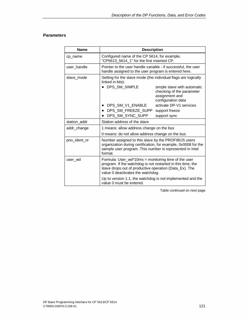
Description of the DP Functions, Data, and Error Codes
DP Base Programming Interface for CP 5613/CP 5614C79000-G8976-C108-01 121
Parameters
Name Description
cp_name Configured name of the CP 5614, for example,"CP5613_5614_1" for the first inserted CP.
user_handle Pointer to the user handle variable - if successful, the userhandle assigned to the user program is entered here.
slave_mode Setting for the slave mode (the individual flags are logicallylinked in bits):� DPS_SM_SIMPLE simple slave with automatic
checking of the parameterassignment andconfiguration data
� DPS_SM_V1_ENABLE activate DP-V1 services� DPS_SM_FREEZE_SUPP support freeze� DPS_SM_SYNC_SUPP support sync
station_addr Station address of the slave
addr_change 1 means: allow address change on the bus
0 means: do not allow address change on the bus
pno_ident_nr Number assigned to this slave by the PROFIBUS usersorganization during certification, for example, 0x0008 for thesample user program. This number is represented in Intelformat.
user_wd Formula: User_wd*10ms = monitoring time of the userprogram. If the watchdog is not restarted in this time, theslave drops out of productive operation (Data_Ex). Thevalue 0 deactivates the watchdog.
Up to version 1.1, the watchdog is not implemented and thevalue 0 must be entered.
Table continued on next page

Description of the DP Functions, Data, and Error Codes
DP Base Programming Interface for CP 5613/CP 5614122 C79000-G8976-C108-01
Table continued from previous page
Name Description
init_data Pointer to a structure with information on the extendedslave data.
Typedef union DPS_INIT_DATA_S
{
struct DPS_SIMPLE_S
{
DPR_WORD user_prm_data_len; // in
DPR_BYTE user_prm_dat
[DPS_MAX_PDU_LEN]; // in
DPR_WORD cfg_data_len; // in
DPR_BYTE cfg_data[DPS_MAX_PDU_LEN];// in
}simple;
struct DPS_DYNAMIC_S
{
DPR_WORD def_cfg_data_len; // in
DPR_BYTE def_cfg_data
[DPS_MAX_PDU_LEN]; // in
}dynamic;
}DPS_INIT_DATA_T
user_prm_data_len: length of the specified userparameter assignment data <=237 bytes
user_prm_data: specified user parameterassignment data
cfg_data_len: length of the specifiedconfiguration data <= 244 bytes
cfg_data: specified configuration data(format see Section 4.7.3)
def_cfg_data_len: length of the default configurationdata <= 244 bytes
def_cfg_data: default configuration data
Note:The first parameter assignment data byte is reserved forthe slave controller and is ignored in the check!
In the DP-V1 mode, the first 3 user parameter assignmentdata bytes are reserved and are ignored in the check!
Table continued on next page

Description of the DP Functions, Data, and Error Codes
DP Base Programming Interface for CP 5613/CP 5614C79000-G8976-C108-01 123
Table continued from previous page
Name Description
max_data Pointer to a structure with the maximum buffer lengths forinput and output data, for user diagnostics, for userparameter assignment data and configuration data andalso for the user set slave address data.
Typedef DPS_MAX_DATA_S
{
DPR_BYTE max_input_data_len; // in
DPR_BYTE max_output_data_len; // in
DPR_BYTE max_user_diag_len; // in
DPR_BYTE max_user_prm_data_len; // in
DPR_BYTE max_cfg_data_len; // in
DPR_BYTE max_user_ssa_data_len; // in
}DPS_MAX_DATA_T
Note:max_user_ssa_data_len needs no entry, if addr_changehas the value 0.
baud_rate Data transmission rate to be set. For the CP 5614,DPS_BD_AUTO_DETECT must be specified since theCP 5614 automatically detects the data transmission rate.
error Address of a structure provided by the user program of thetype DP_ERROR_T - If an error occurred, the structurecontains details for troubleshooting (see Section 4.4).
Return Value
Name Description
DP_OK Successful completion of the function.
otherwise if error -> error_code ==DPS_RET_NO_SLAVE_MODULE
DP slave functions are not availablesince this is a CP 5613 (without a slavemodule).
other Unsuccessful completion of the function.

Description of the DP Functions, Data, and Error Codes
DP Base Programming Interface for CP 5613/CP 5614124 C79000-G8976-C108-01
4.2.3 DPS_close
Purpose
With this function, a DP user program logs off for communication at the slavemodule.
Note 1
If the logoff was successful, the user handle is no longer valid and must notcontinue to be used.
Note 2
To shut down the DP slave, your user program should first change the slavemodule to the OFFLINE mode with the DPS_stop function.
Syntax
DPR_DWORD DPS_close (DPR_DWORD user_handle, // in
DP_ERROR_T *error ); // out
Parameters
Name Description
user_handle User handle assigned with the DPS_open call.
error Address of a structure provided by the user program of thetype DP_ERROR_T. If an error occurred, the structurecontains details for troubleshooting (see Section 4.4).
Return Value
Name Description
DP_OK Successful completion of the function
other Unsuccessful completion of the function

Description of the DP Functions, Data, and Error Codes
DP Base Programming Interface for CP 5613/CP 5614C79000-G8976-C108-01 125
4.2.4 DPS_start
Purpose
This function can be used to switch the slave ONLINE. This is necessary afterinitialization.
After switching the slave OFFLINE with DPS_stop, the slave module can beswitched online again with DPS_start.
Syntax
DPR_DWORD DPS_start(
DPR_DWORD user_handle, // in
DP_ERROR_T *error); // out
Parameters
Name Description
user_handle User handle assigned with the DPS_open call.
error Address of a structure provided by the user program of thetype DP_ERROR_T. If an error occurred, the structurecontains details for troubleshooting (see Section 4.4).
Return Value
Name Description
DP_OK Successful completion of the function
other Unsuccessful completion of the function

Description of the DP Functions, Data, and Error Codes
DP Base Programming Interface for CP 5613/CP 5614126 C79000-G8976-C108-01
4.2.5 DPS_stop
Purpose
This function is used to deactivate the slave module. The slave module then nolonger reacts on the bus.
Syntax
DPR_DWORD DPS_stop (DPR_DWORD user_handle, // in
DP_ERROR_T *error ); // out
Parameters
Name Description
user_handle User handle assigned with the DPS_open call.
error Address of a structure provided by the user program of thetype DP_ERROR_T. If an error occurred, the structurecontains details for troubleshooting (see Section 4.4).
Return Value
Name Description
DP_OK Successful completion of the function
other Unsuccessful completion of the function

Description of the DP Functions, Data, and Error Codes
DP Base Programming Interface for CP 5613/CP 5614C79000-G8976-C108-01 127
4.2.6 DPS_get_baud_rate
Purpose
Using this function, your user program can query the current data transmission rateof the slave module.
Syntax
DPR_DWORD DPS_get_baud_rate(
DPR_DWORD user_handle // in
DPR_WORD *state, // out
DPR_WORD *baud_rate, // out
DP_ERROR_T *error ); // out
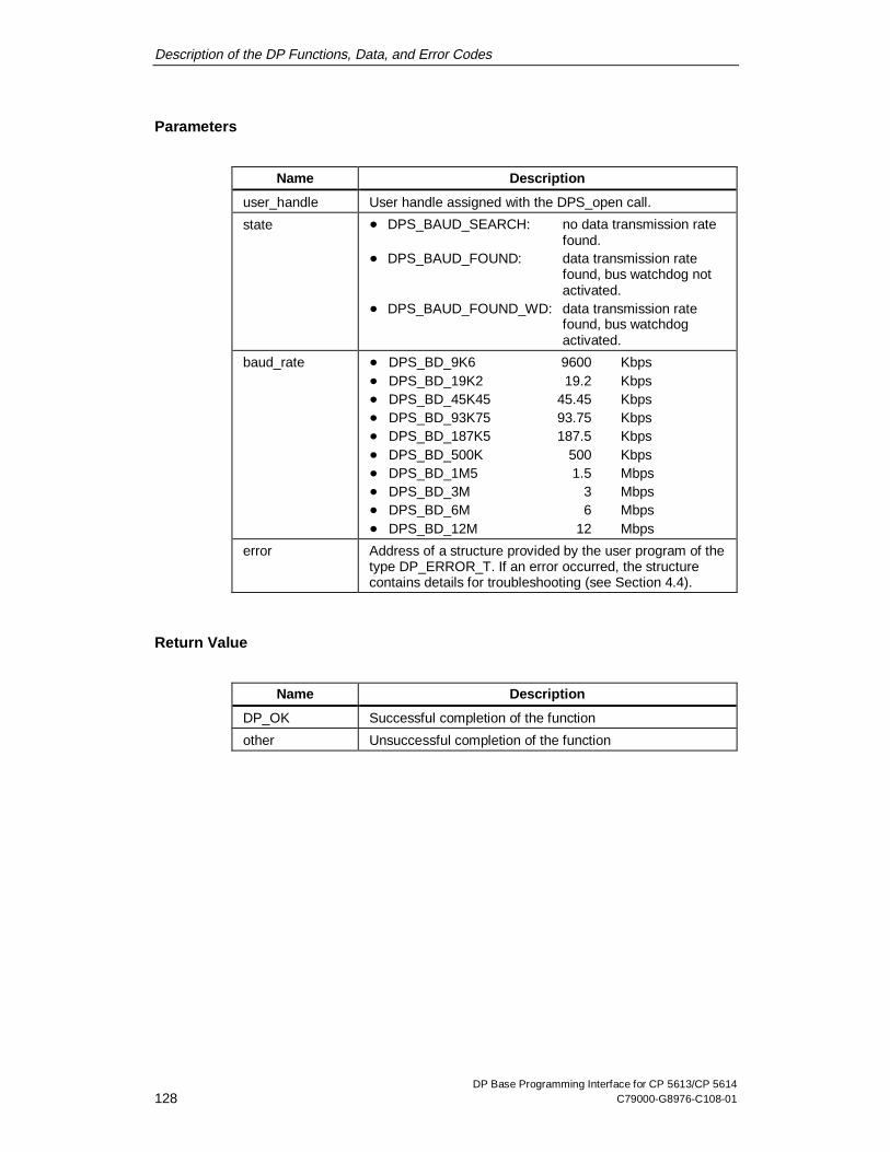
Description of the DP Functions, Data, and Error Codes
DP Base Programming Interface for CP 5613/CP 5614128 C79000-G8976-C108-01
Parameters
Name Description
user_handle User handle assigned with the DPS_open call.
state � DPS_BAUD_SEARCH: no data transmission ratefound.
� DPS_BAUD_FOUND: data transmission ratefound, bus watchdog notactivated.
� DPS_BAUD_FOUND_WD: data transmission ratefound, bus watchdogactivated.
baud_rate � DPS_BD_9K6 9600 Kbps� DPS_BD_19K2 19.2 Kbps� DPS_BD_45K45 45.45 Kbps� DPS_BD_93K75 93.75 Kbps� DPS_BD_187K5 187.5 Kbps� DPS_BD_500K 500 Kbps� DPS_BD_1M5 1.5 Mbps� DPS_BD_3M 3 Mbps� DPS_BD_6M 6 Mbps� DPS_BD_12M 12 Mbps
error Address of a structure provided by the user program of thetype DP_ERROR_T. If an error occurred, the structurecontains details for troubleshooting (see Section 4.4).
Return Value
Name Description
DP_OK Successful completion of the function
other Unsuccessful completion of the function

Description of the DP Functions, Data, and Error Codes
DP Base Programming Interface for CP 5613/CP 5614C79000-G8976-C108-01 129
4.2.7 DPS_get_gc_command
Purpose
This function queries the last received global control command sent by the mastercontrolling this slave. This function simply provides information for the userprogram and no reaction is required by the user program to process the globalcontrol frame.
Syntax
DPR_DWORD DPS_get_gc_command(
DPR_DWORD user_handle, // in
DPR_WORD *gc_cmd, // out
DP_ERROR_T *error); // out
Parameters
Name Description
user_handle User handle assigned with the DPS_open call.
gc_cmd Last received global control command
The global control information is represented in bits. It ispossible that more than one bit is set at the same time. Thestructure corresponds to the "global control byte" of EN50170:
� DPS_CLEAR master is in the CLEAR mode.� DPS_FREEZE inputs are adopted and frozen.� DPS_UNFREEZE inputs are updated cyclically
again.� DPS_SYNC outputs are updated once.� DPS_UNSYNC outputs are updated cyclically
again.
error Address of a structure provided by the user program of thetype DP_ERROR_T. If an error occurred, the structurecontains details for troubleshooting (see Section 4.4).
Description of the DP Functions, Data, and Error Codes
DP Base Programming Interface for CP 5613/CP 5614130 C79000-G8976-C108-01
Return Value
Name Description
DP_OK Successful completion of the function
other Unsuccessful completion of the function
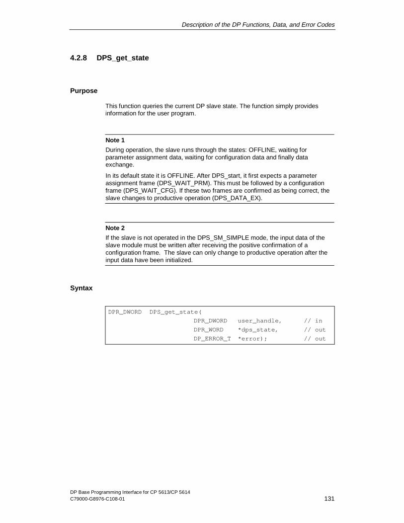
Description of the DP Functions, Data, and Error Codes
DP Base Programming Interface for CP 5613/CP 5614C79000-G8976-C108-01 131
4.2.8 DPS_get_state
Purpose
This function queries the current DP slave state. The function simply providesinformation for the user program.
Note 1
During operation, the slave runs through the states: OFFLINE, waiting forparameter assignment data, waiting for configuration data and finally dataexchange.
In its default state it is OFFLINE. After DPS_start, it first expects a parameterassignment frame (DPS_WAIT_PRM). This must be followed by a configurationframe (DPS_WAIT_CFG). If these two frames are confirmed as being correct, theslave changes to productive operation (DPS_DATA_EX).
Note 2
If the slave is not operated in the DPS_SM_SIMPLE mode, the input data of theslave module must be written after receiving the positive confirmation of aconfiguration frame. The slave can only change to productive operation after theinput data have been initialized.
Syntax
DPR_DWORD DPS_get_state(
DPR_DWORD user_handle, // in
DPR_WORD *dps_state, // out
DP_ERROR_T *error); // out

Description of the DP Functions, Data, and Error Codes
DP Base Programming Interface for CP 5613/CP 5614132 C79000-G8976-C108-01
Parameters
Name Description
user_handle User handle assigned with the DPS_open call.
dps_state • DPS_OFFLINE the slave module has not started up.
• DPS_WAIT_PRM the slave module is waiting for aparameter assignment frame fromthe remote master.
• DPS_WAIT_CFG the slave module is waiting for aconfiguration frame from the remotemaster.
• DPS_DATA_EX the slave module is taking part indata exchange (productive phase).
error Address of a structure provided by the user program of thetype DP_ERROR_T - If an error occurred, the structurecontains details for troubleshooting (see Section 4.4).
Return Value
Name Description
DP_OK Successful completion of the function
other Unsuccessful completion of the function

Description of the DP Functions, Data, and Error Codes
DP Base Programming Interface for CP 5613/CP 5614C79000-G8976-C108-01 133
4.2.9 DPS_set_diag
Purpose
This function transfers diagnostic data to the DP slave module. The CP 5614 slavemodule passes on the data to the master that controls it.
Note
The length of the diagnostic data can vary during operation!The 6 standard diagnostic bytes are managed by the CP 5614 slave module itself.
For more information on the structure and formats of diagnostic information seeSection 4.6.
Syntax
DPR_DWORD DPS_set_diag(DPR_DWORD user_handle, // in
DPR_BYTE *user_diag_data, // in
DPR_WORD user_diag_len, // in
DPR_WORD diag_state, // in
DP_ERROR_T *error ); // out

Description of the DP Functions, Data, and Error Codes
DP Base Programming Interface for CP 5613/CP 5614134 C79000-G8976-C108-01
Parameters
Name Description
user_handle User handle assigned with the DPS_open call.
user_diag_data Pointer to the user diagnostic data from the 7th byteonwards. The first 6 bytes contain the standard informationadded by the slave module hardware. (Format see Section4.6).
user_diag_len Length of the user diagnostic data.
diag_state This bit field can be logically combined bitwise from thefollowing values:• DPS_EXT_DIAG: if set, this is error information,
otherwise a status message.• DPS_EXT_DIAG_OV: there is more diagnostic data
than can be represented in thediagnostic buffer.
• DPS_STAT_DIAG: a serious error has occurredand no more useful data canbe supplied.
error Address of a structure provided by the user program of thetype DP_ERROR_T - If an error occurred, the structurecontains details for troubleshooting (see Section 4.4).
Return Value
Name Description
DP_OK Successful completion of the function
other Unsuccessful completion of the function

Description of the DP Functions, Data, and Error Codes
DP Base Programming Interface for CP 5613/CP 5614C79000-G8976-C108-01 135
4.2.10 DPS_get_ind
Purpose
This function is used to fetch an indication (message from the controlling master).
Note 1
In the call, name the indications you want to receive. You will then receive exactlyone indication as the result.
DPS_CHK_PRM is also signaled if user parameter assignment data length of theremote master is 0. This allows the slave module to reject a set of parameterswithout user data.
Note 2
If there is no indication at the time of the function call and the monitoring time haselapsed, the DPS_get_ind does not wait but returns the value DPS_NO_IND in theindication field.
Note 3
If a function is still waiting for asynchronous indications when DPS_close is sent,DPS_get_ind is terminated with error class DPS_ERROR_USR_ABORT.
Note 4
This call can only be sent a total of once at any one time by one or more programs.

Description of the DP Functions, Data, and Error Codes
DP Base Programming Interface for CP 5613/CP 5614136 C79000-G8976-C108-01
Syntax
DPR_DWORD DPS_get_ind(
DPR_DWORD user_handle, // in
DPR_DWORD *ind_ref, // out
DPR_DWORD timeout, // in
DPR_DWORD *indication, // inout
DPR_WORD *data_len // inout
DPR_BYTE *data_blk // out
DP_ERROR_T *error ); // out
Parameters
Name Description
user_handle User handle assigned with the DPS_open call.
timeout Duration of the maximum wait time (in milliseconds) until thefunction returns.
Limit values:
0: no wait time - the function returns immediately
0x7FFFFFFE: maximum wait time
DP_TIMEOUT_FOREVER: "Endless" wait time
ind_ref Address of the reference number of the indication. Must beincluded again with DPS_set_resp.
Table continued on next page

Description of the DP Functions, Data, and Error Codes
DP Base Programming Interface for CP 5613/CP 5614C79000-G8976-C108-01 137
Table continued from previous page
Name Description
indication In this address, the user enters the indications it wants to beinformed of. These are bits that can be ORed bit by bit. Whenthe function returns, it contains the current indication type(always one indication only).
� DPS_NO_IND: No indication occurred.� DPS_CHK_PRM: New parameter assignment
frame was received andmust be checked by thehost software (only for thedynamic mode, i.e. whenDPS_simple was notselected with DPS_open).
� DPS_CHK_CFG: New configuration framewas received and must bechecked by the hostsoftware (only for thedynamic mode, i.e. whenDPS_simple was notselected with DPS_open).
� DPS_NEW_SSA: Set slave address. Framewas received and must bechecked by the hostsoftware (only whenaddress changes via thebus are permitted).
� DPS_BAUD_CHANGED: The data transmission rateinformation has changed(see DPS_get_baud_rate).
� DPS_GO_LEAVE_DATA_EX: The slave has entered theDPS_DATA_EX state orhas left it (seeDPS_get_state).
� DPS_NEW_GC: A new (modified) globalcontrol frame was received(see DPS_get_gc_command).
data_len Maximum length of the data_blk array when the function iscalled, number of bytes entered when the function returns - Theconstant DPS_MAX_PDU_LEN should be used for the call.
Table continued on next page

Description of the DP Functions, Data, and Error Codes
DP Base Programming Interface for CP 5613/CP 5614138 C79000-G8976-C108-01
Table continued from previous page
Name Description
data_blk The indication data for the particular indication are entered inthis array (see next section: Data Structure).
error Address of a structure provided by the user program of the typeDP_ERROR_T. If an error occurred, the structure containsdetails for troubleshooting (see Section 4.4).
Data Structure (for data_blk parameter)
The content of the data_blk data structure depends of the type of indication.
Indication Content of the data_blk Data Structure
DPS_CHK_PRM DPR_BYTE user_prm_data[ ];
User parameter assignment data of the master, without thestandard section.
DPS_CHK_CFG DPR_BYTE cfg_data[ ];
Configuration data of the master
DPS_NEW_SSA DPR_WORD new_address;DPR_WORD ident_number;
DPR_WORD no_addr_chg;DPR_BYTE user_data[ ];
Data structure containing the new station address, theidentification number, the enabling of address changes, andthe user data.
All information is represented in the Intel format.
DPS_BAUD_CHANGED
DPR_WORD state;DPR_WORD transmission rate;
Data structure , see DPS_get_baud_rate (seeSection 4.2.6).
DPS_GO_LEAVE_DATA_EX
DPR_WORD dps_state;
see DPS_get_state parameter (see Section 4.2.8).
DPS_NEW_GC DPR_WORD gc_command;
see DPS_get_gc_command parameter (see Section 4.2.7).

Description of the DP Functions, Data, and Error Codes
DP Base Programming Interface for CP 5613/CP 5614C79000-G8976-C108-01 139
Return Value
Name Description
DP_OK Successful completion of the function
other Unsuccessful completion of the function

Description of the DP Functions, Data, and Error Codes
DP Base Programming Interface for CP 5613/CP 5614140 C79000-G8976-C108-01
4.2.11 DPS_set_resp
Purpose
With this function, the user program provides the response data of an indicationobtained previously with DPS_get_ind. This is necessary for the indications thatrequire information from the user to control internal processing (DPS_CHK_PRM,DPS_CHK_CFG and DPS_NEW_SSA).
Note
The DPS_BAUD_CHANGED, DPS_GO_LEAVE_DATA_EX, DPS_NEW_GC andDPS_NO_IND must not be confirmed!
Syntax
DPR_DWORD DPS_set_resp(
DPR_DWORD user_handle, // in
DPR_DWORD ind_ref, // in
DPR_WORD data_len, // in
DPR_BYTE *data_blk, // in
DP_ERROR_T *error); // out
Parameters
Name Description
user_handle User handle assigned with the DPS_open call.
ind_ref Reference number returned by DPS_get_ind.
data_len Length of the data in data_blk
data_blk Address of the response data
error Address of a structure provided by the user program of thetype DP_ERROR_T - If an error occurred, the structurecontains details for troubleshooting (see Section 4.4).

Description of the DP Functions, Data, and Error Codes
DP Base Programming Interface for CP 5613/CP 5614C79000-G8976-C108-01 141
Data Structure (for data_blk parameter)
Indication Content of the data_blk Data Structure
DPS_CHK_PRM DPR_WORD status
Value Meaning
DPS_PRM_OK Parameter assignment data accepted.
DPS_PRM_FAULT Parameter assignment not accepted, theslave does not enter data exchange.
DPS_CHK_CFG DPR_WORD status formatting
Value Meaning
DPS_CFG_OK Configuration data accepted.
DPS_CFG_FAULT Configuration not accepted, slave doesnot enter data exchange.
DPS_NEW_SSA DPR_WORD status formatting
Value Meaning
DPS_SSA_OK Set slave address completed.
Return Value
Name Description
DP_OK Successful completion of the function
other Unsuccessful completion of the function

Description of the DP Functions, Data, and Error Codes
DP Base Programming Interface for CP 5613/CP 5614142 C79000-G8976-C108-01
4.2.12 DPS_calc_io_data_len
Purpose
This function calculates the input/output data length from any configuration frame.This function is intended to provide information for the user program, so that it doesnot need to evaluate the ID bytes of the configuration frame itself. Anyconfiguration frame can be evaluated.
Syntax
DPR_DWORD DPS_calc_io_data_len (
DPR_WORD cfg_len, // in
DPR_BYTE *cfg_data, // in
DPR_WORD *in_data_len, // out
DPR_WORD *out_data_len, // out
DP_ERROR_T *error ); // out
Parameters
Name Description
cfg_len Length of the configuration data
cfg_data Pointer to the configuration data
in_data_len Pointer to the calculated input data length
out_data_len Pointer to the calculated output data length
error Address of a structure provided by the user program of thetype DP_ERROR_T. If an error occurred, the structurecontains details for troubleshooting (see Section 4.4).
Return Value
Name Description
DP_OK Successful completion of the function
other Unsuccessful completion of the function

Description of the DP Functions, Data, and Error Codes
DP Base Programming Interface for CP 5613/CP 5614C79000-G8976-C108-01 143
4.3 Access to the Process Image of the CP 5613/CP 5614
Overview of the Existing Data
The following table provides you with an overview of the data available to your userprogram in the process image of the CP 5613/CP 5614.
Category Data
DP process data � Input data of the slaves� Output data of the slaves� Diagnostic data of the slaves, including diagnostic
counter� Slave data change indicator� Input data of the slave module of the CP 5614� Output data of the slave module of the CP 5614
Other information � Information on the DP master� Information on a slave� Slave states� Current bus parameters� Bus statistics
Hardware events � Control of event generation at start of cycle� Control of event generation if input data of slaves
changes� Control of event generation if data of the slave module
on the CP 5614 changes� Control of event generation when diagnostic data is
received from slaves� Query of the fast logic status (for more information on
controlling fast logic hardware events, see Sections4.1.24 and 4.1.25)
The formats of the I/O data and the diagnostic data are described in Sections 4.5and 4.6.

Description of the DP Functions, Data, and Error Codes
DP Base Programming Interface for CP 5613/CP 5614144 C79000-G8976-C108-01
4.3.1 Reading the Input Data of a DP Slave
Consistent Reading
There is a fixed data area in the process image of the CP 5613/CP 5614 for theinput data of each individual slave.
To allow the input data of a slave to be read consistently, your user program firstlocks this data area to prevent it being updated by the DP master, then accessesthe area, and releases it again.
The program locks the area by writing the slave number to a control register in theprocess image. The program releases the area by writing the valueDPR_DP_UNLOCK or a different slave number to the same register.
Example of Consistent Reading
"p" is a pointer to the process image that your user program obtained with the"DP_get_pointer" call. Then 200 bytes of slave no. 5 are copied to a local buffer"buf":
/* Lock the data area against updating * /
p->ctr.D_lock_in_slave_adr = 5;
/ * Copy data * /
memcpy(buf, &p->pi.slave_in[5].data[0], 200);
/* Cancel lock again */
p->ctr.D_lock_in_slave_adr = DPR_DP_UNLOCK;

Description of the DP Functions, Data, and Error Codes
DP Base Programming Interface for CP 5613/CP 5614C79000-G8976-C108-01 145
Reading without Consistency
To read without consistency, the locking and release of the data area are simplyomitted.
! Warning
The lock is canceled by the following:
� Locking a different slave to read its data,� Locking a different slave to read its diagnostic information (Section 4.3.2)� Or by triggering a write job using the corresponding control register (Section
4.3.3).
Note 1
The data is only valid when the master is in the OPERATE or CLEAR/AUTOCLEAR mode and the slave is in the READY state.
Note 2
The memory area with index 127 contains the data of the slave module of theCP 5614.
Note 3
The input data are not updated as long as the slave reports static diagnostic data(Section 4.6.2, byte 2 - stationstatus_2, bit 1).

Description of the DP Functions, Data, and Error Codes
DP Base Programming Interface for CP 5613/CP 5614146 C79000-G8976-C108-01
4.3.2 Reading the Diagnostic Data of a DP Slave
Consistent Reading of the Diagnostic Data
Each individual slave has a fixed data area in the process image of theCP 5613/CP 5614 (for more information on the data format see Section 4.6).
To allow the diagnostic data of a slave to be read consistently, your user programfirst locks this data area to prevent it being updated by the DP master, thenaccesses the area, and releases it again. The program locks the area by writing theslave number to a control register in the process image. The data area is releasedagain by writing the value DPR_DP_UNLOCK to the same register.
There is also a counter that counts the diagnostic data of the relevant slave.
Example of Consistent Reading of the Diagnostic Data
"p" is a pointer to the process image that your user program obtained with the"DP_get_pointer" call. Then 200 bytes of the diagnostic data of slave no. 5 arecopied to a local buffer "buf":
/* Lock the diagnostic data area against updating */
p->ctr.D_lock_diag_slave_adr = 5;
/* Evaluate the counter */
count = p->pi.slave_diag[5].diag_count;
/* Copy current data */
memcpy(buf, &p->pi.slave_diag[5].data[0],p->pi.slave_diag[5].diag_len);
/* Cancel lock again */
p->ctr.D_lock_diag_slave_adr = DPR_DP_UNLOCK;

Description of the DP Functions, Data, and Error Codes
DP Base Programming Interface for CP 5613/CP 5614C79000-G8976-C108-01 147
Reading without Consistency
To read without consistency, the locking and release of the data area are simplyomitted.
General Notes
! Warning
The lock is canceled by the following:� Locking a different slave to read its input data (Section 4.3.1)� Locking a different slave to read its diagnostic information� Triggering a job to write the output data of a slave using the corresponding
control register (Section 4.3.3)
Note 1
The data is only valid when the master is in the STOP, OPERATE, or CLEAR/AUTOCLEAR mode and the slave is configured in the current database.
Note 2
The memory area with index 127 contains the data of the slave module of theCP 5614.
Note 3
Based on the diagnostic counter, you can recognize whether or not new diagnosticdata have been received. The diagnostic counter is incremented each time adiagnostic message is received.

Description of the DP Functions, Data, and Error Codes
DP Base Programming Interface for CP 5613/CP 5614148 C79000-G8976-C108-01
4.3.3 Writing the Output Data of a DP Slave
Writing is always consistent
There is a fixed data area in the process image of the CP 5613/CP 5614 for theoutput data of each individual slave.
To write the output data of a slave consistently, your user program writes the datato the data area and then triggers the acceptance of the data in the next DP cycleby writing the slave number to a control register in the process image of the CP.
Since the data transfer is triggered explicitly, the written output data are alwaysconsistent.

Description of the DP Functions, Data, and Error Codes
DP Base Programming Interface for CP 5613/CP 5614C79000-G8976-C108-01 149
Example of Consistent Writing
"p" is a pointer to the process image that your user program obtained with the"DP_get_pointer" call. Then 200 bytes from a local buffer "buf" are written to slave5 as follows:
/* Copy data */
memcpy(&p->pi.slave_out[5].data[0], buf, 200);
/* Trigger transfer */
p->ctr. D_out_slave_adr = 5;
! Warning
The lock is canceled by the following:� Locking a different slave to read its input data (Section 4.3.1)� Locking a different slave to read its diagnostic information
Note 1
The data is only transferred to the slave when the master is in the OPERATEmode and the slave is in the READY state.
Note 2
The memory area with index 127 contains the data of the slave module of theCP 5614.
Note 3
The output data are not sent as long as the slave reports static diagnostic data(Section 4.6.2, byte 2 - stationstatus_2, bit 1).

Description of the DP Functions, Data, and Error Codes
DP Base Programming Interface for CP 5613/CP 5614150 C79000-G8976-C108-01
4.3.4 Checking the Slaves for Changed Data
Uses of the Data Changed Information
The process image of the CP 5613/CP 5614 contains a memory area where youcan see which slave data have changed.You can use this property to quickly check where data have changed withouthaving to use semaphores.
Example
"p" is a pointer to the process image that your user program obtained with the"DP_get_pointer" call. To count, for example, how many slave have changed data,you would write a program like that shown below, where "sum" contains the result:
unsigned short sum = 0;
unsigned short i;
for (i=0; i < DPR_MAX_SLAVE_ADDR;i++)
{
if ( p->ef.input[i].req_mask == DPR_DATA_CHANGE )
{ /* Changed data found on slave i */
/* Mask released again */
p->ef.input[i].req_mask =DPR_DATA_INT_CLEAR_AND_UNMASK;
sum++;
}
}

Description of the DP Functions, Data, and Error Codes
DP Base Programming Interface for CP 5613/CP 5614C79000-G8976-C108-01 151
General Notes
! Warning
Your user program must first lock the input data of a slave (D_lock_in_slave_addr,Section 4.3.1), then reset "req_mask" if data changes(DPR_DATA_INT_CLEAR_AND_UNMASK), and then read the data itself.Otherwise if events overlap, this may mean that the next data change goesunnoticed.
Note 1
Your user program must reset the mask itself(DPR_DATA_INT_CLEAR_AND_UNMASK).
Note 2
The memory area with index 127 contains the data of the slave module of theCP 5614.
Description of the DP Functions, Data, and Error Codes
DP Base Programming Interface for CP 5613/CP 5614152 C79000-G8976-C108-01
4.3.5 Querying the State of a DP Slave
Uses of the Slave State
Before accessing data, your user program should check the state of a slave, to findout whether or not the data to be read are valid.

Description of the DP Functions, Data, and Error Codes
DP Base Programming Interface for CP 5613/CP 5614C79000-G8976-C108-01 153
Example
"p" is a pointer to the process image that your user program obtained with the"DP_get_pointer" call. To count, for example, how many slaves are in the READYstate, you would write a program like that shown below, where "sum" contains theresult:
unsigned short sum = 0;
unsigned short i;
for (i = 0; i< DPR_MAX_SLAVE_ADDR; i++)
{
if (p->info_watch.slave_info[i].slave_state ==DPR_SLV_READY)
{
sum++; /* found */
}
}
There is also the DPR_SLV_NOT_READY state that also includes non-configuredslaves.
Note 1
The DP master automatically attempts to reinitialize slaves in the NOT READYstate and to include them in cyclic processing.
Note 2
The user program must not overwrite the slave_state variable.
Note 3
The memory area with index 127 contains the state of the slave module of theCP 5614.
Note 4
If the slave is in the READY state, this does not necessarily mean that its data arevalid. Diagnostic data may mean that the validity of the data is restricted.

Description of the DP Functions, Data, and Error Codes
DP Base Programming Interface for CP 5613/CP 5614154 C79000-G8976-C108-01
4.3.6 Querying Information about the DP Master
Uses of the DP Master Information
The process image of the CP 5613/CP 5614 contains a memory area where youcan read out the following information about the DP master:
x Mode (OFFLINE, STOP, CLEAR, AUTOCLEAR, OPERATE)
x Identification number of the certification
x Hardware version
x Firmware version
Example
"p" is a pointer to the process image that your user program obtained with the"DP_get_pointer" call. To display this information in a simple application, you wouldwrite a program similar to that below:
printf("master state -> %ld",p->info_watch.master_info.USIF_state);
/* 0 means OFFLINE */
/* 1 means STOP */
/* 2 means CLEAR */
/* 3 means AUTOCLEAR */
/* 4 means OPERATE */
printf("master ident number -> %lx",p->info_watch.master_info.ident_number);
/* in Motorola format */
printf("master HW version -> %lx",p->info_watch.master_info.hw_version);
/* e.g. 0x00000102 for version 1.2 */
printf("master FW version -> %lx",p->info_watch.master_info.fw_version);
Note
Writing these values is not permitted and does not change the master data.

Description of the DP Functions, Data, and Error Codes
DP Base Programming Interface for CP 5613/CP 5614C79000-G8976-C108-01 155
4.3.7 Querying Current Bus Parameters of the Master
Uses of the Bus Parameter Query
In the process image of the CP 5613/CP 5614, there is a memory area from whichyou can read out the current bus parameters, for example, to display them in youruser program.
Example
"p" is a pointer to the process image that your user program obtained with the"DP_get_pointer" call. To display this information in a simple application, you wouldwrite a program similar to that below:
printf("Baudrate -> %d",p->info_watch. aspc2_buspara.baud_rate);
The parameters are bytes, words or double words. Refer to the header file for theformats, structure DPR_ASPC2_BUSPARA_T.
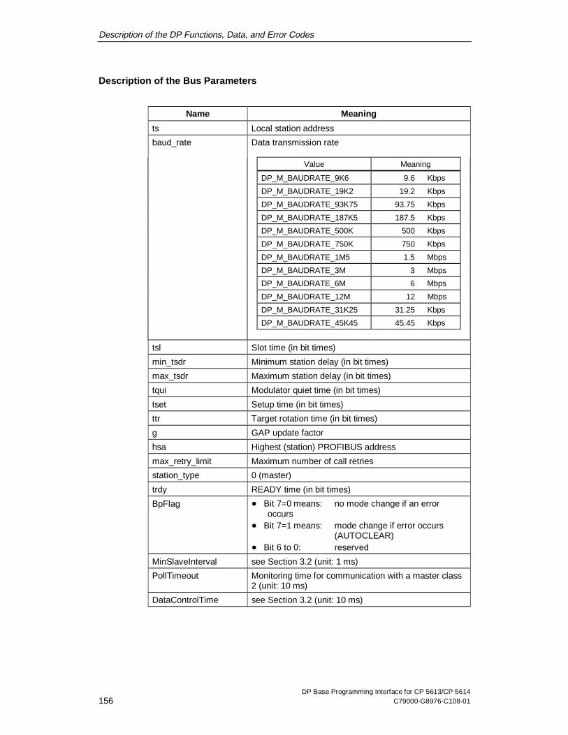
Description of the DP Functions, Data, and Error Codes
DP Base Programming Interface for CP 5613/CP 5614156 C79000-G8976-C108-01
Description of the Bus Parameters
Name Meaning
ts Local station address
baud_rate Data transmission rate
Value Meaning
DP_M_BAUDRATE_9K6 9.6 Kbps
DP_M_BAUDRATE_19K2 19.2 Kbps
DP_M_BAUDRATE_93K75 93.75 Kbps
DP_M_BAUDRATE_187K5 187.5 Kbps
DP_M_BAUDRATE_500K 500 Kbps
DP_M_BAUDRATE_750K 750 Kbps
DP_M_BAUDRATE_1M5 1.5 Mbps
DP_M_BAUDRATE_3M 3 Mbps
DP_M_BAUDRATE_6M 6 Mbps
DP_M_BAUDRATE_12M 12 Mbps
DP_M_BAUDRATE_31K25 31.25 Kbps
DP_M_BAUDRATE_45K45 45.45 Kbps
tsl Slot time (in bit times)
min_tsdr Minimum station delay (in bit times)
max_tsdr Maximum station delay (in bit times)
tqui Modulator quiet time (in bit times)
tset Setup time (in bit times)
ttr Target rotation time (in bit times)
g GAP update factor
hsa Highest (station) PROFIBUS address
max_retry_limit Maximum number of call retries
station_type 0 (master)
trdy READY time (in bit times)
BpFlag � Bit 7=0 means: no mode change if an erroroccurs
� Bit 7=1 means: mode change if error occurs(AUTOCLEAR)
� Bit 6 to 0: reserved
MinSlaveInterval see Section 3.2 (unit: 1 ms)
PollTimeout Monitoring time for communication with a master class2 (unit: 10 ms)
DataControlTime see Section 3.2 (unit: 10 ms)

Description of the DP Functions, Data, and Error Codes
DP Base Programming Interface for CP 5613/CP 5614C79000-G8976-C108-01 157
Note
Writing these values is not permitted and does not change the bus parametersactually used.
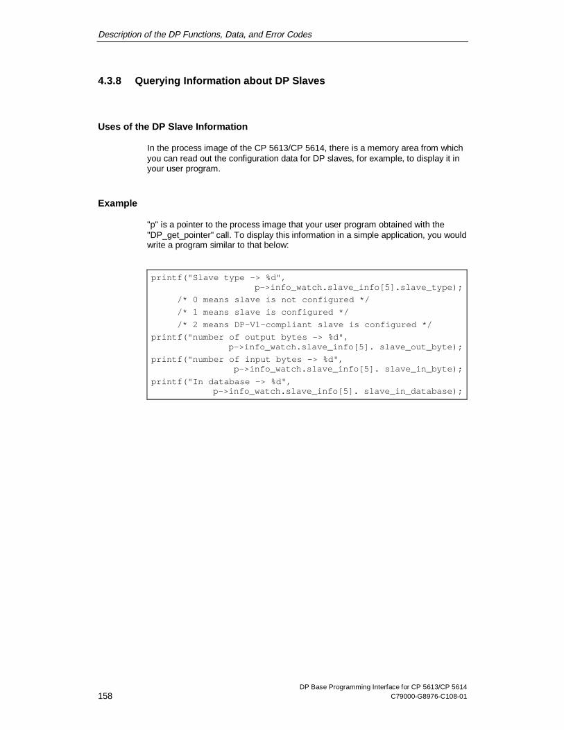
Description of the DP Functions, Data, and Error Codes
DP Base Programming Interface for CP 5613/CP 5614158 C79000-G8976-C108-01
4.3.8 Querying Information about DP Slaves
Uses of the DP Slave Information
In the process image of the CP 5613/CP 5614, there is a memory area from whichyou can read out the configuration data for DP slaves, for example, to display it inyour user program.
Example
"p" is a pointer to the process image that your user program obtained with the"DP_get_pointer" call. To display this information in a simple application, you wouldwrite a program similar to that below:
printf("Slave type -> %d",p->info_watch.slave_info[5].slave_type);
/* 0 means slave is not configured */
/* 1 means slave is configured */
/* 2 means DP-V1-compliant slave is configured */
printf("number of output bytes -> %d",p->info_watch.slave_info[5]. slave_out_byte);
printf("number of input bytes -> %d",p->info_watch.slave_info[5]. slave_in_byte);
printf("In database -> %d",p->info_watch.slave_info[5]. slave_in_database);

Description of the DP Functions, Data, and Error Codes
DP Base Programming Interface for CP 5613/CP 5614C79000-G8976-C108-01 159
4.3.9 Reading PROFIBUS Statistical Data
Overview
In the process image of the CP 5613/CP 5614 there is a memory area in which theCP stores statistical data of the connected PROFIBUS network allowing, forexample, diagnostic programs to read them.
Example of Access
"p" is a pointer to the process image that your user program obtained with the"DP_get_pointer" call. To count, for example, the counter for the bus short-circuitsdetected up to now, you would write a program like the following:
/* Output counter for bus short-circuits */
printf("bus ctrl err =%u\n",p->info_watch.aspc2_event.bus_control_error);
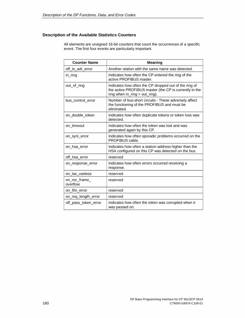
Description of the DP Functions, Data, and Error Codes
DP Base Programming Interface for CP 5613/CP 5614160 C79000-G8976-C108-01
Description of the Available Statistics Counters
All elements are unsigned 16-bit counters that count the occurrences of a specificevent. The first four events are particularly important.
Counter Name Meaning
off_ts_adr_error Another station with the same name was detected.
in_ring Indicates how often the CP entered the ring of theactive PROFIBUS master.
out_of_ring Indicates how often the CP dropped out of the ring ofthe active PROFIBUS master (the CP is currently in thering when in_ring > out_ring).
bus_control_error Number of bus-short circuits - These adversely affectthe functioning of the PROFIBUS and must beeliminated.
on_double_token Indicates how often duplicate tokens or token loss wasdetected.
on_timeout Indicates how often the token was lost and wasgenerated again by this CP.
on_syni_error Indicates how often sporadic problems occurred on thePROFIBUS cable.
on_hsa_error Indicates how often a station address higher than theHSA configured on this CP was detected on the bus.
off_hsa_error reserved
on_response_error Indicates how often errors occurred receiving aresponse.
on_las_useless reserved
on_rec_frame_overflow
reserved
on_fifo_error reserved
on_req_length_error reserved
off_pass_token_error Indicates how often the token was corrupted when itwas passed on.

Description of the DP Functions, Data, and Error Codes
DP Base Programming Interface for CP 5613/CP 5614C79000-G8976-C108-01 161
4.3.10 Querying the Fast Logic Status
Overview
In the process image of the CP 5613/CP 5614, there is a memory area in whichyou can check whether data exchange with fast logic has taken place.
For the software version in which this property is available, refer to the versiontable in Section in the Installation Instructions.

Description of the DP Functions, Data, and Error Codes
DP Base Programming Interface for CP 5613/CP 5614162 C79000-G8976-C108-01
4.3.11 Activating/Deactivating the Generation of Hardware Events
Overview
In the process image of the CP 5613/CP 5614, there is a memory area in whichyou can activate the triggering of hardware events for a new DP cycle, datachanges, or the arrival of diagnostic data.
Hardware events for changes in slave input data and diagnostic data can be setseparately for each individual slave.
The events are indicated by incrementing semaphores.
Example of Activation
"p" is a pointer to the process image that your user program obtained with the"DP_get_pointer" call. To activate events at the start of the cycle, when datachanges and when diagnostic data arrive, you would write a program like the onebelow:
/* Activate event at the start of the cycle */
p->ctr.D_cycle_start_mask = 0;
/* Activate event if slave 5 data changes 5 */
p->ef.input[5].req_mask = DPR_DATA_INT_CLEAR_AND_UNMASK;
/* Activate event if diagnostic data arrivefrom slave 5 */
p->ef.diag[5].req_mask = DPR_DATA_INT_CLEAR_AND_UNMASK;
Afterwards, when events arrive, the semaphores initialized by your user programwith DP_init_sema_object are incremented.The other possible values for "req_mask" are:
x DPR_DATA_INT_CLEAR_AND_MASK – Waiting for an event, but then nosetting of the semaphore, and
x DPR_DATA_CHANGE – an event has arrived.

Description of the DP Functions, Data, and Error Codes
DP Base Programming Interface for CP 5613/CP 5614C79000-G8976-C108-01 163
Example of Deactivation
The following activation sequence would be canceled by your user program asfollows:
/* Deactivate event for cycle start */
p->ctr.D_cycle_start_mask = 1;
/* Deactivate event for slave 5 data change */
p->ef.input[5].req_mask = DPR_DATA_INT_CLEAR_AND_MASK;
/* Deactivate event if diagnostic data arrivefrom slave 5 */
p->ef.diag[5].req_mask = DPR_DATA_INT_CLEAR_AND_MASK;
Note 1
If your user program has not yet passed through a semaphore, it will not beincremented again. When the program passes through a semaphore, you shouldtherefore always check whether multiple events have already occurred.
Note 2
When a hardware event is received, the corresponding control condition is reset sothat your user program must set it again. This avoids overload on your PC whenyour user program does not process hardware events quickly enough.
Note 3
The use of hardware events for a lot of active slaves at the same time puts greaterload on the PC than polling; refer to the suggestions in the FAQ list.

Description of the DP Functions, Data, and Error Codes
DP Base Programming Interface for CP 5613/CP 5614164 C79000-G8976-C108-01
4.3.12 Sending Data with the CP 5614 as DP Slave
Integration in the Process Image of the CP 5613/CP 5614
The send data of the slave module are in the output image with slave index 127.Writing the output data area with slave index 127 supplies the slave module withnew data that the controlling master reads as inputs.
Example of Consistent Writing
"p" is a pointer to the process image that your user program obtained with the"DP_get_pointer" call. Then 200 bytes from a local buffer "buf" are written to theslave module as send data as follows:
/* Copy data */
memcpy(&p->pi.slave_out[127].data[0], buf, 200);
/* Trigger transfer */
p->ctr. D_out_slave_adr = 127;
The data is now transferred to the slave module. Here, the controlling master canread the data as inputs.
Note
The send data are only accepted by the master when the slave module of theCP 5614 is in the READY state and the master is in the CLEAR, AUTOCLEAR orOPERATE mode.

Description of the DP Functions, Data, and Error Codes
DP Base Programming Interface for CP 5613/CP 5614C79000-G8976-C108-01 165
4.3.13 Receiving Data with the CP 5614 as DP Slave
Integration in the Process Image of the CP 5613/CP 5614
The received data of the slave module are stored in the input image with slaveindex 127. This allows the user program to read the data sent by the controllingmaster as outputs to the slave module by reading the input data area with slaveindex 127.
Example of Consistent Reading
"p" is a pointer to the process image that your user program obtained with the"DP_get_pointer" call. Then 200 bytes of the received data of the slave module arecopied to a local buffer "buf":
/* Lock the data area against updating */
p->ctr.D_lock_in_slave_adr = 127;
/* Copy data */
memcpy(buf, &p->pi.slave_in[127].data[0], 200);
/* Cancel lock again */
p->ctr.D_lock_in_slave_adr = DPR_DP_UNLOCK;
The copied data is the received data of the slave module that the controlling mastersent as outputs.
Reading without Consistency
To read without consistency, the locking and release of the data area are simplyomitted.
General Notes
Note
The data are only valid when the slave module of the CP 5614 is in the READYstate and the master controlling the slave is in the OPERATE mode.

Description of the DP Functions, Data, and Error Codes
DP Base Programming Interface for CP 5613/CP 5614166 C79000-G8976-C108-01
4.3.14 Sending Diagnostic Data with the CP 5614 as DP Slave
Integration in the CP 5613/CP 5614
The slave module of the CP 5614 can transfer its diagnostic data to the controllingmaster. The diagnostic data area with slave index 127 is not used (since thisfunctions only in the receive direction), but rather a C function.
For information on the format of the diagnostic data, see Section 4.6.
Example of Sending Diagnostic Data
"h" is the user handle obtained by your user program with the DPS_open call. Then10 bytes of the user diagnostic data of the slave module are sent as follows from alocal buffer "buf":
/* Transfer diagnostic data to the slave module * /
DPS_set_diag(h, diag_buf, 10, 0, &err);
Note
The diagnostic data are only accepted by the master when the slave module of theCP 5614 is in the READY state and the master controlling the slave is in theCLEAR, AUTOCLEAR or OPERATE mode.

Description of the DP Functions, Data, and Error Codes
DP Base Programming Interface for CP 5613/CP 5614C79000-G8976-C108-01 167
4.4 Error Codes
Uniform Error Structure DP_ERROR_T
The error identifiers for the individual jobs have a uniform structure DP_ERROR_T.If an error occurs, the various elements return the exact description of the error.
typedef struct DP_ERROR
{
DPR_DWORD error_class;
DPR_DWORD error_code;
DPR_BYTE error_decode;
DPR_BYTE error_code_1;
DPR_BYTE error_code_2;
} DP_ERROR_T;

Description of the DP Functions, Data, and Error Codes
DP Base Programming Interface for CP 5613/CP 5614168 C79000-G8976-C108-01
error_class Structure Element
The error_class structure element specifies the general error class. The entry inerror_class is identical to the return value of the function call.
A DP application can therefore evaluate either the error_class structure element orthe return value of the function call.
The table describes the possible error classes and shows which of the otherstructure elements of DP_ERROR_T are valid for the individual error classes.
Error Class Description
DP_OK No error, the job was executed and the resultsare available.
DP_OK_ASYNC Job was execution was triggered successfully,the confirmation is not yet available. The resultmust be fetched later by a DP_get_result call.
This result is only possible with asynchronousjobs.
DP_ERROR_EVENT The slave returns an error coding in theresponse frame for a DPC1 request(ds_write/read, alarm_acknowledge).
DP_ERROR_EVENT_NET Error in PROFIBUS communication, for example,connection abort
DP_ERROR_REQ_PAR Incorrect transferred parameter for a call or callillegal.
DP_ERROR_CI Error accessing the CP
DP_ERROR_RES Not enough resources available
DP_ERROR_USR_ABORT Active jobs aborted because the user programhas logged off (only possible withDP_get_result).

Description of the DP Functions, Data, and Error Codes
DP Base Programming Interface for CP 5613/CP 5614C79000-G8976-C108-01 169
error_code Structure Element
The error_code structure element is relevant in the error classes:
x DP_ERROR_EVENT_NET
x DP_ERROR_REQ_PAR
x DP_ERROR_CI
x DP_ERROR_RES
x DP_ERROR_USR_ABORT
error_decode, error_code_1, error_code_2
The error_decode, error_code_1 and error_code_2 structure elements are onlyrelevant in the DP_ERROR_EVENT error class. In this case, all three elementsmust be evaluated. They contain an error coding that a DP-V1 slave can return inthe response frame after a DP-V1 request.
Description of the Error Classes
The following Figure 4 shows how a DP user program evaluates errors when a DPfunction is called.
ErrClass = DP_xxx
Fetch confirmationwith DP_get_result
Job executed,evaluate return
parameters
Error_decode,evaluate
error_code1/2
Evaluate error_code(DP_get_err_txt)
ErrClass?
DP_OK DP_OK_ASYNC
DP_ERROREVENT
Other
Figure 4 Evaluation of the Return Values

Description of the DP Functions, Data, and Error Codes
DP Base Programming Interface for CP 5613/CP 5614170 C79000-G8976-C108-01
Meaning of the Errors
The "5613_ret.h" file contains an overview of the error messages. A detaileddescription is displayed when the function DP_get_err_txt is called.

Description of the DP Functions, Data, and Error Codes
DP Base Programming Interface for CP 5613/CP 5614C79000-G8976-C108-01 171
4.4.1 Entries in the error_decode, error_code_1 and error_code_2 Struc-ture Elements
Description
This section describes the entries in the following structure elements:
x error_decode
x error_code_1
x error_code_2
Entries are only relevant in the error class DP_ERROR_EVENT. All threeparameters must be evaluated together.
They contain error information sent by the DP-V1 slave.
error_decode
The error_decode parameter specifies the meaning of the parameterserror_code_1 and error_code_2. The following table shows the range of values:
Values Meaning
0 to 127 reserved
128 DP V1
129 to 253 reserved
254 PROFIBUS FMS
255 HART®

Description of the DP Functions, Data, and Error Codes
DP Base Programming Interface for CP 5613/CP 5614172 C79000-G8976-C108-01
Error_Decode = PROFIBUS_FMS, HART ®
The Error_Decode values PROFIBUS FMS and HART® indicate that theparameters Error_Code_1 and Error_Code_2 must be interpreted as defined in therelevant protocols.
With PROFIBUS FMS:
Error_Code Parameter Meaning
Error_Code_1 Error_Class _FMS
Error_Code_2 Error_Code_FMS
With HART ®:
Error_Code Parameter Meaning
Error_Code_1 see HART specification
Error_Code_2 see HART specification
Error_Decode = DP V1
The parameters Error_Code_1 and Error_Code_2 contain the error informationspecific to DP-V1.
Structure of Error_Code_1 with DP-V1
The error coding strategy of DP V1 uses Error_Code_1 to classify the error (class)and to specify an additional error code.
MSB LSB
7 6 5 4 3 2 1 0
CodeClass

Description of the DP Functions, Data, and Error Codes
DP Base Programming Interface for CP 5613/CP 5614C79000-G8976-C108-01 173
Error_Code_1
The possible values of code and class are shown in the following table:
Byte Structure Meaning
Class Code Class Code
0 to 9 any reserved reserved
10 0 application read error
1 write error
2 module failure
3 to 7 reserved
8 version conflict
9 feature not supported
10 to 15 user specific
11 0 access invalid access
1 write length error
2 invalid slot
3 type conflict
4 invalid area
5 state conflict
6 access denied
7 invalid range
8 invalid parameter
9 invalid type
10 to 15 user specific
12 0 resource read constrain conflict
1 write constrain conflict
2 resource busy
3 resource unavailable
4 to 7 reserved
8 to 15 user specific
13 to 15 any user specific user specific

Description of the DP Functions, Data, and Error Codes
DP Base Programming Interface for CP 5613/CP 5614174 C79000-G8976-C108-01
Structure of Error_Code_2 with DP-V1
The Error_Code_2 parameter is user-specific.

Description of the DP Functions, Data, and Error Codes
DP Base Programming Interface for CP 5613/CP 5614C79000-G8976-C108-01 175
4.5 Formats of the Slave Data
Order of the Slave Data
The order of the data corresponds to the configured input/output ports of the DPslaves.
For example, the input ports of an ET 200B 16DI station are stored as follows: port0 in the first byte, port 1 in the 2nd byte etc.
Format of Data Words
The following order is necessary for storing values in the word format (2-bytenumbers):
First, the high byte (lower order address) of the word is entered followed by the lowbyte (higher order address), in other words in Motorola format.
Note 1
This order does not correspond to the format of processors belonging to the80x86/Pentium family!
Note 2
Take into account any additional information from the vendor of the slaves youruser program should support.
Description of the DP Functions, Data, and Error Codes
DP Base Programming Interface for CP 5613/CP 5614176 C79000-G8976-C108-01
4.6 Formats of the Slave Diagnostic Data
Explanation
In some cases, in the following data structures single bits in the bytes aresignificant. The bits are numbered as follows: the least significant bit has thenumber 0 and the most significant bit has the number 7.

Description of the DP Functions, Data, and Error Codes
DP Base Programming Interface for CP 5613/CP 5614C79000-G8976-C108-01 177
4.6.1 Overview of the Entire Structure
Possible Length
The typical length of diagnostic data is between 6 and 32 bytes. The maximumpossible length is 244 bytes.
Header and up to Three Following Fields
Diagnostic data have a fixed header and up to three further fields:
Header Always exists,fixed length
Device-relateddiagnostics
Optional,variable length
ID-related diagnostics Optional,variable length
Channel-relateddiagnostics
Optional,variable length
Identification of the Optional Parts
At the beginning of the optional parts there is a unique coding to distinguish onepart from another.
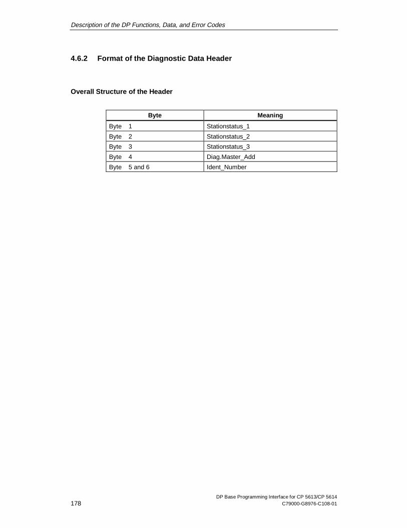
Description of the DP Functions, Data, and Error Codes
DP Base Programming Interface for CP 5613/CP 5614178 C79000-G8976-C108-01
4.6.2 Format of the Diagnostic Data Header
Overall Structure of the Header
Byte Meaning
Byte 1 Stationstatus_1
Byte 2 Stationstatus_2
Byte 3 Stationstatus_3
Byte 4 Diag.Master_Add
Byte 5 and 6 Ident_Number
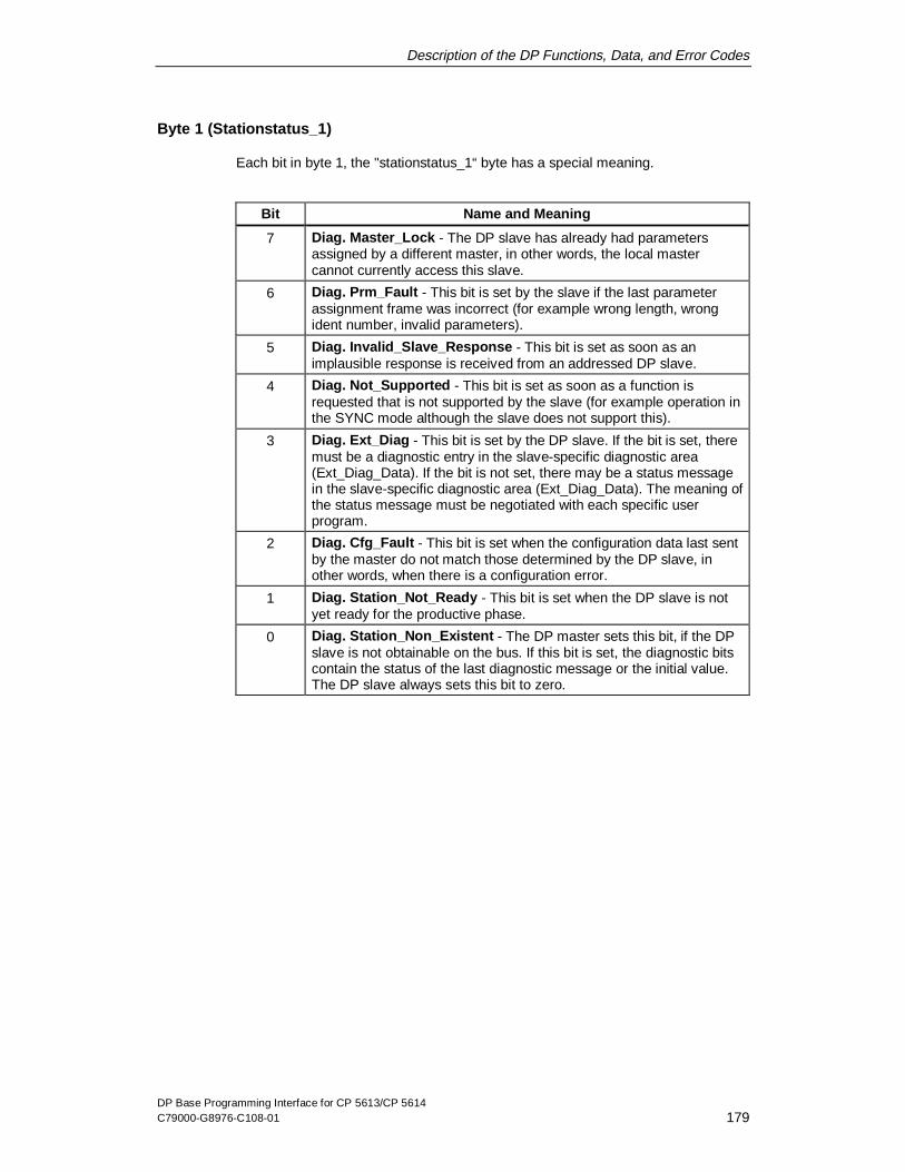
Description of the DP Functions, Data, and Error Codes
DP Base Programming Interface for CP 5613/CP 5614C79000-G8976-C108-01 179
Byte 1 (Stationstatus_1)
Each bit in byte 1, the "stationstatus_1“ byte has a special meaning.
Bit Name and Meaning
7 Diag. Master_Lock - The DP slave has already had parametersassigned by a different master, in other words, the local mastercannot currently access this slave.
6 Diag. Prm_Fault - This bit is set by the slave if the last parameterassignment frame was incorrect (for example wrong length, wrongident number, invalid parameters).
5 Diag. Invalid_Slave_Response - This bit is set as soon as animplausible response is received from an addressed DP slave.
4 Diag. Not_Supported - This bit is set as soon as a function isrequested that is not supported by the slave (for example operation inthe SYNC mode although the slave does not support this).
3 Diag. Ext_Diag - This bit is set by the DP slave. If the bit is set, theremust be a diagnostic entry in the slave-specific diagnostic area(Ext_Diag_Data). If the bit is not set, there may be a status messagein the slave-specific diagnostic area (Ext_Diag_Data). The meaning ofthe status message must be negotiated with each specific userprogram.
2 Diag. Cfg_Fault - This bit is set when the configuration data last sentby the master do not match those determined by the DP slave, inother words, when there is a configuration error.
1 Diag. Station_Not_Ready - This bit is set when the DP slave is notyet ready for the productive phase.
0 Diag. Station_Non_Existent - The DP master sets this bit, if the DPslave is not obtainable on the bus. If this bit is set, the diagnostic bitscontain the status of the last diagnostic message or the initial value.The DP slave always sets this bit to zero.

Description of the DP Functions, Data, and Error Codes
DP Base Programming Interface for CP 5613/CP 5614180 C79000-G8976-C108-01
Byte 2 (Stationstatus_2)
Each bit in byte 2, the "station_status_2“ byte has a special meaning.
Bit Meaning
7 Diag. Deactivated - This bit is set as soon as the DP slave isindicated as inactive in the local parameter record and was taken outof cyclic processing.
6 reserved
5 Diag. Sync_Mode - This bit is set by the DP slave as soon as itreceives the Sync control command.
4 Diag. Freeze_Mode - This bit is set by the DP slave as soon as itreceives the Freeze control command.
3 Diag. WD_On (Watchdog on) - This bit is set by the DP slave. If thisbit is set to 1, the watchdog monitoring is activated on the DP slave.
2 The DP slave always sets this bit to 1.
1 Diag.Stat_Diag (Static Diagnostics) - If the DP slave sets this bit,the DP master must fetch diagnostic information until the bit iscleared. The DP slave, for example, sets this bit when it is notcapable of providing valid user data.
0 Diag. Prm_Req - If the DP slave sets this bit, it must be reassignedparameters and be reconfigured. This bit remains set until parametershave been assigned (if bit 1 and bit 0 are set, bit 0 has the higherpriority).
Byte 3 (Stationstatus_3)
Bit Meaning
7 Diag. Ext_Diag_Overflow - If this bit is set, there is more diagnosticdata than can be indicated. The DP slave sets this bit, for example,when there is more channel diagnostic data than the DP slave canenter in its send buffer. The DP master also sets this bit when the DPslave sends more diagnostic data than the DP master canaccommodate in its diagnostic buffer.
6 to 0 reserved
Byte 4 (Diag. Master_Add )
The address of the DP master that assigned parameters to the DP slave is enteredhere. If the DP slave has not been assigned parameters by a DP master, the DPslave sets the address 255 in this byte.

Description of the DP Functions, Data, and Error Codes
DP Base Programming Interface for CP 5613/CP 5614C79000-G8976-C108-01 181
Bytes 5 and 6 (Ident_Number)
The vendor ID for a DP slave type is assigned in bytes 5 and 6, the"Ident_Number“ byte. This identifier can be used on the one hand for test purposesand on the other for precise identification of the slave.The value is in Motorola format, in other words the higher order part is in byte 5.

Description of the DP Functions, Data, and Error Codes
DP Base Programming Interface for CP 5613/CP 5614182 C79000-G8976-C108-01
4.6.3 Format of the Device-Related Diagnostic Data (Standard DP Slave)
Meaning
With standard DP slaves (without the DPC1 extensions), this field contains generaldiagnostic information such as overtemperature, undervoltage or overvoltage. Thecoding is specified by the slave vendor. For further evaluation, the Ident_Number ofthe slave is required.
Structure
Byte Meaning
Byte 1 Header byte
Bytes2 to 63
Diagnostic_User_Data
Byte 1 (Header Byte)
The two most significant bits in the first byte have the value 00. This identifies theentire field as "device-related diagnostics".
The remaining six bits specify the length of the data field including the first byte.

Description of the DP Functions, Data, and Error Codes
DP Base Programming Interface for CP 5613/CP 5614C79000-G8976-C108-01 183
4.6.4 Format of the Device-Related Diagnostic Data (Slaves with DP-V1Extensions)
Meaning
With these slaves, the device-related diagnostic data contains alarm data or statusmessages. The status messages also include the variant "module status".
Entire Structure with Two Variants
The device-related diagnostic data exists in two variants: alarms and statusmessages. Some components therefore have different codings.
The two variants can be distinguished by byte 2, bit 7.
Byte "Alarms" Variant "Status Messages" Variant
Byte 1 Header byte
Byte 2 Alarm_Type Status_Type
Byte 3 Slot number
Byte 4 Alarm specifier Status specifier
Byte 5to 63
Diagnostic_User_Data
Byte 1 (Header Byte)
The two most significant bits in the first byte have the value 00. This identifies theentire field as "device-related diagnostics".
The remaining six bits specify the length of the data field including the first byte.

Description of the DP Functions, Data, and Error Codes
DP Base Programming Interface for CP 5613/CP 5614184 C79000-G8976-C108-01
Byte 2 (Alarm_Type Variant)
Bit Meaning
7 Value Meaning
0 Alarm
6 to 0 Alarm_Type
0 = reserved1 = Diagnostic alarm2 = Process alarm3 = Pull alarm4 = Plug alarm5 = Status alarm6 = Update alarm7-31 = reserved32-126 = Vendor-specific127 = reserved
Byte 2 (Status_Type Variant)
Bit Meaning
7 Value Meaning
1 Status message
6 to 0 Status_Type
0 = reserved1 = Status message2 = Module status3-31 = reserved32-126 = Vendor-specific127 = reserved
Byte 3 (Slot Number Variant)
Bit Meaning
7 to 0 Slot number

Description of the DP Functions, Data, and Error Codes
DP Base Programming Interface for CP 5613/CP 5614C79000-G8976-C108-01 185
Byte 4 (Alarm Specifier Variant)
Bit Meaning
7 to 3 Seq_Nr Unique identifier of an alarm message
2 Add_Ack If this bit is set, the DP-V1 master indicates that inaddition to the DPC1 Alarm Acknowledge, aseparate user confirmation(for example in the formof a Write service) is required.
1 to 0 Alarm specifier 0 = no further information
1 = Alarm enters state, slot problemThe slot generates an alarm due to anerror/fault.
2 = Alarm leaves state, slot OKThe slot generates an alarm and indicatesthat the slot no longer has an error/fault.
3 = Alarm leaves state, slot still has problemThe slot generates an alarm and indicatesthat the slot still has an error/fault.
Byte 4 (Status Specifier Variant)
Bit Meaning
7 to 2 reserved
1 to 0 Status specifier
0 = no further information1 = status enters state2 = status leaves state3 = reserved

Description of the DP Functions, Data, and Error Codes
DP Base Programming Interface for CP 5613/CP 5614186 C79000-G8976-C108-01
Byte 5-63
User-Specific Information
These bytes contain data with additional user-specific information. The format isdescribed in the slave documentation.
With the "status messages" variant and the "Module_Status" setting (see byte 2),two bits are assigned to each module/slot. The module status is byte-oriented,unused bits are set to 0.
MSB LSB
7 6 5 4 3 2 1 0
Byte 5: Module_Status 4
Module_Status 3
Module_Status 2
Module_Status 1
... ... ... ... ...
Byte m: Module_Status n
Module_Statusn-1
... ...
The status bits are coded as follows:
Bit Meaning
00 Data valid
01 Data invalid: the data of the corresponding module are invalid due toan error/fault (for example short-circuit)
10 Data invalid/wrong module: the data of the corresponding module areinvalid because the module is wrong
11 Data invalid/ no module: the data of the corresponding module areinvalid because no module is inserted
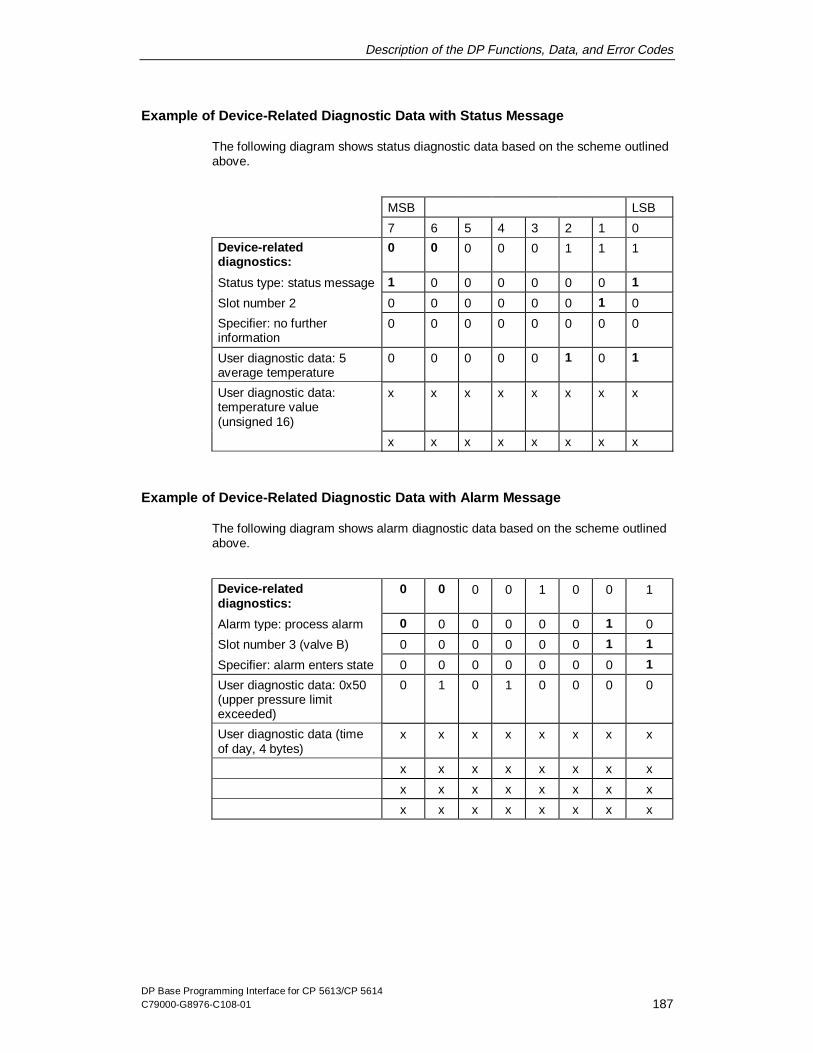
Description of the DP Functions, Data, and Error Codes
DP Base Programming Interface for CP 5613/CP 5614C79000-G8976-C108-01 187
Example of Device-Related Diagnostic Data with Status Message
The following diagram shows status diagnostic data based on the scheme outlinedabove.
MSB LSB
7 6 5 4 3 2 1 0
Device-relateddiagnostics:
0 0 0 0 0 1 1 1
Status type: status message 1 0 0 0 0 0 0 1
Slot number 2 0 0 0 0 0 0 1 0
Specifier: no furtherinformation
0 0 0 0 0 0 0 0
User diagnostic data: 5average temperature
0 0 0 0 0 1 0 1
User diagnostic data:temperature value(unsigned 16)
x x x x x x x x
x x x x x x x x
Example of Device-Related Diagnostic Data with Alarm Message
The following diagram shows alarm diagnostic data based on the scheme outlinedabove.
Device-relateddiagnostics:
0 0 0 0 1 0 0 1
Alarm type: process alarm 0 0 0 0 0 0 1 0
Slot number 3 (valve B) 0 0 0 0 0 0 1 1
Specifier: alarm enters state 0 0 0 0 0 0 0 1
User diagnostic data: 0x50(upper pressure limitexceeded)
0 1 0 1 0 0 0 0
User diagnostic data (timeof day, 4 bytes)
x x x x x x x x
x x x x x x x x
x x x x x x x x
x x x x x x x x

Description of the DP Functions, Data, and Error Codes
DP Base Programming Interface for CP 5613/CP 5614188 C79000-G8976-C108-01
4.6.5 Format of ID-Related Diagnostics
Meaning
Module-specific diagnostics is possible for modular slaves with an ID byte permodule. The DP master sends ID bytes to the slave in a configuration frame duringthe startup phase. In the ID-related diagnostic data each module is assigned a bitin the data field. If a bit is set, this means that there is diagnostic information on thecorresponding module.
Identification of the ID-Related Diagnose Data and Length in the First Byte
The two most significant bits in the first byte have the value 01.
The remaining six bits specify the length of the data field including the first byte.
Content of the Data Field
The remaining bytes of the data field contain a bit array. The least significant bit ofthe 2nd byte has the index 0 and so on in ascending order so that, for example, themost significant bit of the 3rd byte has index 15.
The bits indicate whether or not diagnostic data were signaled for the ID index.
Meaning of the Bits in the Diagnostic Byte
Each bit in the "diagnostic bytes“ has a special meaning.
Note
Refer to the example at the end of Section 4.6.6.

Description of the DP Functions, Data, and Error Codes
DP Base Programming Interface for CP 5613/CP 5614C79000-G8976-C108-01 189
4.6.6 Format of Channel-Related Diagnostics
Meaning
A channel is identified by the slot of the module and the channel number. A slot(module) can consist of several channels (for example, analog module with twochannels each with 4 bits).Here, the data organization of the channel and messages such as "undervoltage"or "short-circuit" are supplied for the individual channels of a module.
Note
Refer to the example later in the section.
Sequence of Entries each with Three Bytes
Channel-related diagnostic data consists of a sequence of entries all with the sameformat and three bytes long (header byte, channel number, type of diagnosticinformation).
Header Byte (ID Number) with Identification
The two most significant bits in the first byte of each entry have the value 10.
The remaining six bits in the first byte indicate the ID number. In ID-relateddiagnostics, the appropriate bit is set for the ID number.

Description of the DP Functions, Data, and Error Codes
DP Base Programming Interface for CP 5613/CP 5614190 C79000-G8976-C108-01
Channel Number
Bit Meaning
7 and 6 Value Meaning
00 reserved
01 Input
10 Output
11 Input/output
5 to 0 Channel number 0 to 63
Note
If ID bytes contain both input and output, the direction of the diagnostic channel isindicated in bit 7 and bit 6 of the channel number.

Description of the DP Functions, Data, and Error Codes
DP Base Programming Interface for CP 5613/CP 5614C79000-G8976-C108-01 191
Type of Diagnostics
Bit Meaning
7 and 6 Channel type
Channel type Meaning
000 reserved
001 bit
010 2 bits
011 4 bits
100 byte
101 word
110 2 words
111 reserved
5 to 0 Error type
Error type Meaning
0 reserved
1 Short circuit
2 Undervoltage
3 Overvoltage
4 Overload
5 Overtemperature
6 Wire break
7 Upper limit value exceeded
8 Below lower limit value
9 Error
10 - 15 reserved
16 - 31 Specified by the vendor

Description of the DP Functions, Data, and Error Codes
DP Base Programming Interface for CP 5613/CP 5614192 C79000-G8976-C108-01
Example: Structure of Diagnostic Information According the Above Scheme
The following figure represents diagnostic information arranged according to thescheme listed above.
MSB LSB
7 6 5 4 3 2 1 0
Header 6 bytes long
Device-relateddiagnostics:
0 0 0 0 0 1 0 0
(Header byte) device-specific
The meaning of the bits is diagnostics field,
Specified by the vendor here 3 bytes long
ID-related diagnostics:(Header byte)
0 1 0 0 0 1 0 1
ID number 0with diag info(diagnostic byte)
0
7.
0
6.
0
5.
0
4.
0
3.
0
2.
0
1.
1
0.
ID number 12with diag info(diagnostic byte)
0
15.
0
14.
0
13.
1
12.
0
11.
0
10.
0
9.
0
8.
ID number 18with diag info(diagnostic byte)
0
23.
0
22.
0
21.
0
20.
0
19.
1
18.
0
17.
0
16.
(diagnostic byte) 0
31.
0
30.
0
29.
0
28.
0
27.
0
26.
0
25.
0
24.
Channel-relateddiagnostics:
ID number 0(header byte)
1 0 0 0 0 0 0 0
Channel 2(channel number)
0 0 0 0 0 0 1 0
Overload, channelorganized in bits(type of diagnostics)
0 0 1 0 0 1 0 0
ID number 12(header byte)
1 0 0 0 1 1 0 0
Channel 6(channel number)
0 0 0 0 0 1 1 0
Upper limit value exceeded,channel organized in words(type of diagnostics)
1 0 1 0 0 1 1 1

Description of the DP Functions, Data, and Error Codes
DP Base Programming Interface for CP 5613/CP 5614C79000-G8976-C108-01 193
4.7 Format of the Slave Parameter Data
Definition
This section describes the format of the slave parameter data as obtained by theDP_read_slv_par call described in Section 4.1.11. There are three variantspossible that are selected by the value of the "type" parameter in theDP_read_slv_par call:
Variant Value of the "type" Parameter
General slave parameters DP_SLV_TYP
Parameter assignment data DP_SLV_PRM
Configuration data DP_SLV_CFG
The structure of the three variants is described below in greater detail.

Description of the DP Functions, Data, and Error Codes
DP Base Programming Interface for CP 5613/CP 5614194 C79000-G8976-C108-01
4.7.1 Structure of the General Slave Parameters
Overview
The components are bytes. They are byte-aligned, in other words, they are locatedone immediately following the other. The parameters shown on a gray backgroundare only relevant for DP slaves with DP-V1 additional functions. Where necessarythe parameters are described in more detail later in the section.
Name Meaning (see below)
Sl_Flag Activates fail-safe mechanisms etc.
Slave_Typ Specified by the vendor
Max_Diag_Data_Len Max. length of the diagnostic data
Max_Alarm_Len Max. length of alarm data
Max_Channel_Data_Len Max. length of DPC1 frame
Diag_Upd_Delay Diagnostic counter
Alarm_Mode Max. number of simultaneous alarms
Add_Sl_Flag Data for AUTOCLEAR etc.
Bytes 1 to 6 reserved
Byte Structure
In some cases, in the following data structures single bits in the bytes aresignificant. The bits are numbered as follows: the least significant bit has thenumber 0 and the most significant bit has the number 7.

Description of the DP Functions, Data, and Error Codes
DP Base Programming Interface for CP 5613/CP 5614C79000-G8976-C108-01 195
Sl_Flag
This parameter contains slave-related flags.
Each bit in the "SI_Flag“ byte has a special meaning.
Bit Meaning
7 Active
0 means: DP slave is not activated
1 means: DP slave is activated
6 New_Prm
0 means: DP slave receives user data
1 means: DP slave receives new parameter assignment data
5 Fail_Safe
0 means: DP slave receives bytes with content 0 in the CLEAR mode
1 means: DP slave receives empty frames in the CLEARmode
4 reserved
3 DPV1_Supported
0 means: DP slave functionality complying with EN 50170
1 means: DP slave functionality complying with DP-V1
2 DP-V1 data types
0 means: DP slave configuration data complying with EN50170
1 means: DP slave configuration data complying with DP-V1
1 Extra alarm SAP
0 means: DP master acknowledges alarms via SAP 51
1 means: DP master acknowledges alarms via SAP 50
0 reserved
Slave Type
This parameter contains a vendor-specific type identifier for the slave unit.
Value Meaning
0 Standard DP slave
1 to 15 reserved
16 to 255 Specified by the vendor

Description of the DP Functions, Data, and Error Codes
DP Base Programming Interface for CP 5613/CP 5614196 C79000-G8976-C108-01
Alarm_Mode
This parameter specifies the maximum number of possible active alarms.
Value Meaning
0 1 alarm of each alarm type
1 2 alarms in total
2 4 alarms in total
3 8 alarms in total
4 12 alarms in total
5 16 alarms in total
6 24 alarms in total
7 32 alarms in total
Add_Sl_Flag
Bit Name and Meaning
7-2 reserved
1 Ignore_AClr
0 means: execute AUTOCLEAR
1 means: ignore AUTOCLEAR
0 NA_To_Abort
0 means: the slave is not initialized if it does not respond.
1 means: the slave is reinitialized if it does not respond.

Description of the DP Functions, Data, and Error Codes
DP Base Programming Interface for CP 5613/CP 5614C79000-G8976-C108-01 197
4.7.2 Structure of the Parameter Assignment Data
Overview
The parameter assignment data consist of bus-specific data and DP slave-specificdata.
Byte Number Meaning
Byte 1 Station_status
Byte 2 WD_Fact_1
Byte 3 WD_Fact_2
Byte 4 Min. Station Delay Responder
Byte 5-6 Ident_Number
Byte 7 Group_Ident
Byte 8 DPV1_Status_1
Byte 9 DPV1_Status_2
Byte 10 DPV1_Status_3
Byte 11-n User_Prm_Data

Description of the DP Functions, Data, and Error Codes
DP Base Programming Interface for CP 5613/CP 5614198 C79000-G8976-C108-01
Byte 1 (Station_status)
Byte 1 "Station_status" has the following structure:
Each bit in the "station_status“ byte has a special meaning.
Bit Meaning
7 and 6 Lock_Req and Unlock_Req
Bit 7 Bit 6 Meaning
0 0 The min TSDR is overwritten when parametersare assigned. All other parameters remainunchanged.
0 1 The DP slave is released for other masters.
1 0 The DP slave is disabled for other masters, allparameters are adopted(exception: min TSDR = 0).
1 1 The DP slave is released for other masters.
5 Sync_Req
This bit indicates to the slave that it must operate in the Sync modeas soon as the command is transferred with the dpn_global_crtl()function.
4 Freeze_Req
This bit indicates to a DP slave that it must operate in the freezemode as soon as the command is transferred with thedpn_global_ctrl() function.
3 Watchdog
If this bit is set to zero, the watchdog monitoring is deactivated. If thebit is set, the watchdog monitoring is activated on the DP slave.
2 to 0 reserved
Bytes 2 and 3 (WD_Fact_1 and WD_Fact_2)
These two bytes contain factors for setting the watchdog time (TWD).
The watchdog ensures that if this time expires after a DP master has failed, theoutputs are set to a safe state.
TWD [ms] = 10 * WD_Fact_1 * WD_Fact_2

Description of the DP Functions, Data, and Error Codes
DP Base Programming Interface for CP 5613/CP 5614C79000-G8976-C108-01 199
Byte 4 (Min. Station Delay Responder)
This is the time that the DP slave must wait before it is allowed to send itsresponse frames to the DP master, unit: bit times.
Bytes 5 and 6 (Ident_Number)
This number is assigned by the vendor. The DP slave only accepts parameterassignment frames when the Ident_Number transferred with the parameterassignment data matches its own Ident_Number. The value is transferred inMotorola format, in other words, the higher order half is in byte 5.
Byte 7 (Group_Ident)
With this parameter, a group can be formed for the DP_global_ctrl() function. Eachbit represents a group. The Group_Ident is accepted only when the Lock_Req bit isset (see byte 1).
Byte 8 (DPV1_Status_1)
Bit Meaning
7 DPV1_Enable
This bit is set to activate the DP-V1 functionality of a DP-V1 slave. Ifthe bit is not set, the slave operates in the compatibility modewhenever possible.
6 Fail Safe
This bit is set to show that the slave operates in the fail-safe mode.
5-3 reserved
2 WD_Base_1ms
If this bit is set, the watchdog time is calculated according to thefollowing formula:TWD [ms] = WD_Fact_1 * WD_Fact 2
If the bit is not set, the watchdog time is calculated as follows:TWD [ms] = 10 * WD_Fact_1 * WD_Fact 2
1 to 0 reserved

Description of the DP Functions, Data, and Error Codes
DP Base Programming Interface for CP 5613/CP 5614200 C79000-G8976-C108-01
Byte 9 (DPV1_Status_2)
Bit Meaning
7 Enable_Pull_Plug_Alarm
This bit is set to allow an alarm of the type "Pull_Plug_Alarm" to besignaled.
6 Enable_Process_Alarm
This bit is set to allow an alarm of the type "Process_Alarm" to besignaled.
5 Enable_Diagnostic_Alarm
This bit is set to allow an alarm of the type "Diagnostic_Alarm" to besignaled.
4 Enable_Manufacturer_Specific_Alarm
This bit is set to allow all vendor-specific alarms to be signaled.
3 Enable_Status_Alarm
This bit is set to allow an alarm of the type "Status_Alarm" to besignaled.
2 Enable_Update_Alarm
This bit is set to allow an alarm of the type "Update_Alarm" to besignaled.
1 reserved
0 Check_Cfg_Mode
This bit can be used to influence the reaction to the reception ofconfiguration data. If the bit is set to 0, the check is as described inEN 50170. If this bit is set, the check is made according to a specificuser definition.

Description of the DP Functions, Data, and Error Codes
DP Base Programming Interface for CP 5613/CP 5614C79000-G8976-C108-01 201
Byte 10
DPV1_Status_3
Bit Meaning
7-3 reserved
2-0 Alarm Mode
Bit 4 Meaning
0 1 alarm of each type
1 2 alarms in total
2 4 alarms in total
3 8 alarms in total
4 12 alarms in total
5 16 alarms in total
6 24 alarms in total
7 32 alarms in total
Bytes 11 to n
User_Prm_Data
This byte can be used for parameters specific to a DP slave (for example,diagnostic filter, controller parameters). The meaning and the range of values arespecified by the specific vendor.

Description of the DP Functions, Data, and Error Codes
DP Base Programming Interface for CP 5613/CP 5614202 C79000-G8976-C108-01
4.7.3 Structure of the Configuration Data
Overview of the Structure
The configuration data contain the range of the input and output data areas andinformation on data consistency.
They consist of a sequence of data fields, each data field having one of twoalternative formats:
Confi guration data
Data field 1
Data field 2
...
Data field n
Variant 1
ID byte
Variant 2
Special ID byte
1. Length byte (optional)
2. Length byte (optional)
Vendor-specific data(optional)
The two data block variants can be distinguished by bits 4 and 5 of the first byte.
Length of the Configuration Data
The length of the configuration data is ideally 1 to 32. If necessary, however, up to244 bytes are possible.

Description of the DP Functions, Data, and Error Codes
DP Base Programming Interface for CP 5613/CP 5614C79000-G8976-C108-01 203
Structure of an ID Byte
Each bit has a special meaning.
Bit Meaning
0 to 3 Number of data units - 1
3 means for example 4 data units of the length specified in bit 6
4 and 5 Input/output
Bit 5 Bit 4 Meaning
0 0 does not occur (see below)
0 1 Input
1 0 Output
1 1 input/output
6 Length of the data units
0 means: the data unit is in bytes
1 means: the data unit is 2 bytes
7 Consistency
0 means: byte or word consistency
1 means: consistency over the entire length
Structure of a Special ID Byte
Special identifier formats allow the configuration to be extended by increasing theflexibility. Each bit in the ID byte has a special meaning.
Bit Meaning
0 to 3 Length of the vendor-specific data
These bits contain the length of the vendor-specific data.
4 and 5 These bits always have the value 00.
6 and 7 Input/output
Bit 7 Bit 6 Meaning
0 0 No optional bytes follow
0 1 1 length byte for inputs follows
1 0 1 length byte for outputs follows
1 1 This is followed by� 1 length byte for outputs� 1 length byte for inputs
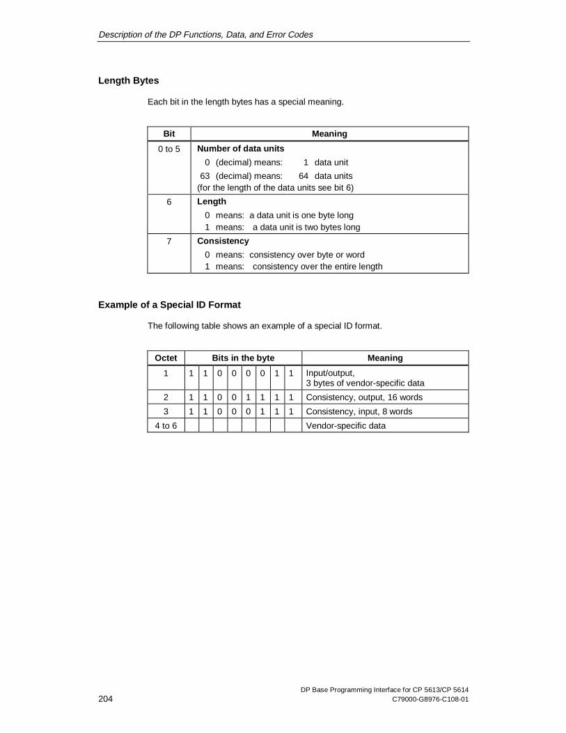
Description of the DP Functions, Data, and Error Codes
DP Base Programming Interface for CP 5613/CP 5614204 C79000-G8976-C108-01
Length Bytes
Each bit in the length bytes has a special meaning.
Bit Meaning
0 to 5 Number of data units
0 (decimal) means: 1 data unit
63 (decimal) means: 64 data units(for the length of the data units see bit 6)
6 Length
0 means: a data unit is one byte long1 means: a data unit is two bytes long
7 Consistency
0 means: consistency over byte or word1 means: consistency over the entire length
Example of a Special ID Format
The following table shows an example of a special ID format.
Octet Bits in the byte Meaning
1 1 1 0 0 0 0 1 1 Input/output,3 bytes of vendor-specific data
2 1 1 0 0 1 1 1 1 Consistency, output, 16 words
3 1 1 0 0 0 1 1 1 Consistency, input, 8 words
4 to 6 Vendor-specific data

DP Base Programming Interface for CP 5613/CP 5614C79000-G8976-C108-01 205
FAQ (Frequently Asked Questions)
5This chapter contains answers to typical questions ("Frequently Asked Questions")on the programming interface of the CP 5613 and CP 5614 arranged in categories.
For information on creating your user program, refer to the sections on structuringuser programs and the check list for programmers.
You should also read the FAQ list in the Installation Instructions of the product.

FAQ (Frequently Asked Questions)
DP Base Programming Interface for CP 5613/CP 5614206 C79000-G8976-C108-01
5.1 FAQs about the Range of Functions of the Product
Which software versions exist and how do they differ from each other?
Please refer to the version table in Section of the Installation Instructions.
Which operating systems are supported?
Please refer to the version table in Section of the Installation Instructions.
Which compilers and programming languages are supported?
Please refer to the version table in Section of the Installation Instructions.
For linking to Borland C++ and Delphi, please check with the AIXO company(Internet: http://www.aixo.com).By designing the "dp_base.dll" with standard calling conventions, linking to otherdevelopment environments is in principle possible.
What are the differences between the CP 5613 and CP 5614?
The CP 5614 has an additional DP port with which the PC can be operated as aDP slave on a second PROFIBUS network. There is also a transfer function for theautomatic transfer of slave data to the controlling master.
Do the CP 5613 and CP 5614 also support the DP programming interf ace of theCP 5412(A2), the CP 5511 and CP 5611?
A further product "DP 5613/Windows NT" is intended for this purpose.
Are multiple CPUs, user programs and CPs supported?
Multiple CPUs in one PC: yes.
Please refer to the version table in Section of the Installation Instructions.

FAQ (Frequently Asked Questions)
DP Base Programming Interface for CP 5613/CP 5614C79000-G8976-C108-01 207
Is the user watchdog supported?
Please refer to the version table in Section of the Installation Instructions.
Are the CP 5613 and CP 5614 OPC-compliant?
OPC products that support the CP 5613/CP 5614 are planned.
What are the reaction times and data transfer rates available with theCP 5613/CP 5614?
Please refer to the numeric data in Section of the Installation Instructions.
FAQ (Frequently Asked Questions)
DP Base Programming Interface for CP 5613/CP 5614208 C79000-G8976-C108-01
5.2 FAQs about Structuring the User Program
Can DP and DPC1 be operated at the same time?
Yes. The DP master must, however, already by in the OPERATE mode beforeDPC1 functions can be used.
How many DPC1 jobs can be sent at the same time?
Per slave address, up to two DPC1 jobs can be sent at any one time, one forreading or writing and one for alarm acknowledge.
How can I structure my user program?
There are basically three wait mechanisms that you can combine together:
x You can poll with your user program, in other words, it queries the processimage cyclically.
x You can use hardware events with semaphores as the wait mechanism.
x You can call the DP_get_event function with a timeout value to wait for softwareevents.
You can also break down your user program into several threads (see also the"ExamComp" sample program.).
What are the advantages of simply polling in the user program?
The program structure is relatively simple (assuming that your program does notuse any other interfaces that would require event handling such as DPC1). Pollingis particularly suitable when you expect a lot of data traffic due to a fast datatransmission rate and a lot of slaves with fast changing data.
FAQ (Frequently Asked Questions)
DP Base Programming Interface for CP 5613/CP 5614C79000-G8976-C108-01 209
What are the disadvantages of simply polling in the user program?
If your user program does not restrict itself, the entire available CPU performanceof the of the PC will be used to query the process image unnecessarily often. If theprogram restricts itself too much, on the other hand, the data will no longer be up todate. We recommend that you restrict polling using a time control suitable for yoursystem.
What are the advantages of hardware events ?
Your user program can react to changes quickly. Since it waits, it does not take upunnecessary CPU time on the PC.
What are the disadvantages of hardware events?
If your user program monitors a large number of active slaves using hardwareevents, the overheads for fetching events is high because semaphores mustconstantly be incremented and run through. This increases PC-CPU load. If youtherefore have a lot of slaves or very active slaves, we recommend that you usehardware events for only a few slaves and poll the others periodically.
What are the advantages of programming with multiple threads?
With multiple threads, you achieve a clearer structure in your user program. This isparticularly useful when you want to run different processes at the same time, forexample, periodic polling combined with hardware events on the one hand andasynchronous DPC1 jobs on the other. These unrelated tasks with their differentdynamic characteristics can be implemented in two threads.
What are the disadvantages of programming with multiple threads?
The threads of an application, for example, must not interfere with each other whenaccessing global variables. Overwriting data and deadlocks must be avoided. It isparticularly important to avoid multiple threads accessing the process image of theCP 5613 or CP 5614 at the same time otherwise they will overwrite the eachother's control register for consistent reading and writing of slave data. This could,for example, jeopardize the consistency of the slave data currently being read by athread.

FAQ (Frequently Asked Questions)
DP Base Programming Interface for CP 5613/CP 5614210 C79000-G8976-C108-01
How do I access the process image with more than one thread?
This is not recommended. The control register for consistent reading and writing ofslave data can then be overwritten, so that, for example, the consistency of theslave data currently being read by a thread would be jeopardized.To avoid this, some form of interlock would be necessary so that only one threadcan access the process image at any one time. You could do this usingsemaphores, mutexes etc. in Windows NT.
How can I access the process image with multiple programs?
This works fine as long all the programs involved release the pointer to the processimage again with the DP_release_pointer call. In real-time operation, we wouldadvise against this, since both calls take up time and you would need to implementextra mechanisms to coordinate the programs.

FAQ (Frequently Asked Questions)
DP Base Programming Interface for CP 5613/CP 5614C79000-G8976-C108-01 211
5.3 FAQ Check List for Programmers
What are the most important aspects of the program structure?
Make sure that you keep to the rules below when structuring your program:
x Begin your user program with a DP_start_cp, DP_open and DP_get_pointerand always complete these with DP_release_pointer, DP_close andDP_reset_cp.
x Evaluate all errors and check all the diagnostic data.
x Check that all the conditions necessary for validating the data are met (forexample, when reading slave data, the master must be in the OPERATE orCLEAR mode and the slave in the READY state).
x Read out alarms with DP_read_alarm and acknowledge them withDP_alarm_ack.
x Events can be reported in any order; so make sure that your algorithms aresuitably flexible.
x Do not send more than one asynchronous DPC1 job to a slave at the same time(DP_ds_read/DP_ds_write, DP_alarm_ack).
x If the result of a DP_enable_event call has been fetched, it must be sent again.
Should I retain the pointer while my program is running?
As long as your user program is in possession of the pointer to the process image(DP_get_pointer call), no other user program can access it. In this case, retain thepointer until the end of the program. If you only access the process imagesporadically, for example, as a diagnostic program or when you do not have real-time requirements, you should release the pointer after every access or cycle.
FAQ (Frequently Asked Questions)
DP Base Programming Interface for CP 5613/CP 5614212 C79000-G8976-C108-01
What are the most important aspects of accessing data areas?
The process image is separate from the user program and the slaves. Note theinformation in Section 2.7.
Use the check list below for your data areas:
x Select data buffer lengths to match the longest possible data.
x Link job fields with valid data buffers in the startup phase of your program.
x If you use multiple threads, each thread should have its own job fields and databuffers.
x Interlock the threads if they can access the dual-port RAM at the same time, toavoid access conflicts.
What are the most important aspects of using hardware events andsemaphores?
x Until your user program has run through a semaphore for hardware events, itwill not be incremented again. After running through a semaphore, you shouldtherefore check whether or not more than one event has occurred. (This isunnecessary with software events.)
x After a hardware event arrives, the triggering control condition is reset so thatyour user program must then set it again.
x Your user program must log off with DP_delete_sema_object and not withWindows API functions.
How can I wait for more than one event in a thread at the same time?
Initialize a semaphore for each event type (DP_create_sema_object), trigger yourjobs and then wait at the semaphores by calling the Win32 API function"WaitForMultipleObjects" or “sgWaitForMultipleObjects".
Where can I find a list of all the error messages?
In the header files "5613_ret.h" and "5614_ret.h". To decode the error messages,use the DP_get_err_txt function.

FAQ (Frequently Asked Questions)
DP Base Programming Interface for CP 5613/CP 5614C79000-G8976-C108-01 213
What should a user programmer take into account?
x Use unique order_ids for parallel jobs.
x Remember that a hardware event entering the state deletes its activationcondition. You must make sure it is reactivated.
x Do not use hardware events at the same time as periodic polling on the sameslave.

FAQ (Frequently Asked Questions)
DP Base Programming Interface for CP 5613/CP 5614214 C79000-G8976-C108-01
5.4 FAQs about Debugging and Starting Up Your Program
What are the typical errors when a program is first run?
x Bus malfunctions caused by bad contacts/bad cabling/forgetting the terminatorare often the cause of initial problems.
x Incorrectly configured slave types
x Using the wrong database
x Bad bus parameters
x Wrong station addresses set on the slaves
Are there tools for troubleshooting?
Use the diagnostic tools described in the Installation Instructions for theCP 5613/CP 5614. You can start these tools from the start menu of Windows NT.These tools also include a trace of the DP function calls.

FAQ (Frequently Asked Questions)
DP Base Programming Interface for CP 5613/CP 5614C79000-G8976-C108-01 215
5.5 FAQs Miscellaneous Programming Questions
Can groups of slaves be used for hardware events?
You can do this yourself with the software tools, for example: at the start of eachcycle, activate the hardware events of all slaves in the group and, as soon as anevent occurs, deactivate them all again until the end of the cycle.
What names are given to the modules when they are installed?
The modules are given the names "CP5613_5614_1", "CP5613_5614_2" etc. bythe driver.
What differences are there in the user program for a CP 5614 and a CP 5613?
With a CP 5613, the "DPS_open" call returns the message that no slave exists;see Section 4.2.2.
How can I use the CP 5613 or CP 5614 with a real-time kernel in Windows NTwithout having to port all the drivers etc.?
Implement the CP startup and log off in Windows NT. In the meantime, operate theCP in the real-time kernel only by accessing the process image. The alarm usedand also data are entered in the structure "info_watch.pci" in the process imageeach time the Windows NT driver is started (see header file "dp_5613.h"). AWindows NT user program can read this from here and pass it on to a real-timekernel.
Who can I contact if I have problems?
Read the chapter "Where to Get Help" in the Installation Instructions for theproduct.
Further information for programmers is also available from the following address:http://www.ad.siemens.de/net/html_00/index.shtml

FAQ (Frequently Asked Questions)
DP Base Programming Interface for CP 5613/CP 5614216 C79000-G8976-C108-01

DP Base Programming Interface for CP 5613/CP 5614C79000-G8976-C108-01 217
Where to Get Help
6This Chapter lists contacts for SIMATIC NET:
Contacts for technical questions
Contacts for training with SIMATIC NET products

Where to Get Help
DP Base Programming Interface for CP 5613/CP 5614218 C79000-G8976-C108-01
6.1 Help with Technical Questions
Documentation
You will find information on the use of this software in the following sources:
x in the corresponding paper documentation
x in the online help (F1 key)
x in the text files on the product diskettes
x in text and PDF files on the SIMATIC NET CD
Who to Contact
If you cannot find answers to technical questions on the software in the sourceslisted above, please contact your local Siemens office.
You will find the addresses:
x in our catalog IK 10
x on the Internet (http://www.ad.siemens.de)
x in the "README.TXT" in the main folder of the SIMATIC NET CD
Common Questions
Our customer support on the Internet provides useful information and answers tofrequently asked questions (FAQ). Under FAQ, you will find information about ourentire range of products.
The address of the A&D home page in the World Wide Web of the Internet is asfollows:
x http://www.ad.siemens.de/net

Where to Get Help
DP Base Programming Interface for CP 5613/CP 5614C79000-G8976-C108-01 219
SIMATIC Customer Support Hotline
Available at all times worldwide:
SIMATIC Basic Hotline
NurembergSIMATIC BASIC Hotline SIMATIC Premium Hotline
(charged, only with SIMATIC card)
Local time: Mo to Fr 7:00 to 17:00 (CET)Phone: +49 (911) -895-7000Fax: +49 (911) -895-7002E-mail: [email protected]
Local time: Mo to Fr 0:00 to 24:00 (CET)Phone: +49 (911) -895-7777Fax: +49 (911) -895-7001
Johnson CitySIMATIC BASIC Hotline
SingaporeSIMATIC BASIC Hotline
Local time: Mo to Fr 8:00 to 17:00Phone: +1 423 461-2522Fax: +1 423 461-2231E-mail: [email protected]
Local time: Mo to Fr 8:30 to 17:30Phone: +65 740-7000Fax: +65 740-7001E-mail: [email protected]
Johnson CityNuremberg
Singapore

Where to Get Help
DP Base Programming Interface for CP 5613/CP 5614220 C79000-G8976-C108-01
SIMATIC Customer Support Online Services
In its online services, SIMATIC Customer Support provides you with wide-rangingadditional information about SIMATIC products:
x You will find general, up-to-date information:
– on the Internet (http://www.ad.siemens.de/simatic)
– using fax polling
x You can obtain the latest product information and downloads:
– on the Internet (http://www.ad.siemens.de/support/html-00).
– via the Bulletin Board System (BBS) of the SIMATIC Customer Supportmailbox in Nuremberg (Tel.: +49 (911) - 895-7100).
To contact the mailbox, use a modem with up to 28.8 Kbps, V.34(parameters: 8, N, 1, ANSI) or ISDN (parameters: x.75, 64 Kbps).

Where to Get Help
DP Base Programming Interface for CP 5613/CP 5614C79000-G8976-C108-01 221
6.2 Contacts for training with SIMATIC NET
SIMATIC Training Center
Please contact your regional training center or the central training center in D-90327 Nuremberg, Tel. +49-911-895-3154.

Where to Get Help
DP Base Programming Interface for CP 5613/CP 5614222 C79000-G8976-C108-01

DP Base Programming Interface for CP 5613/CP 5614C79000-G8976-C108-01 223
Index
7
AActive..................................................... 16Add_Sl_Flag .........................................196Alarm ..................................................... 93Alarm acknowledge................................ 96Alarm Mode ..........................................201Alarm specifier ......................................185Alarm_Mode .........................................196Alarm_Type ..........................................184Asynchronous ........................................ 67
get result ...........................................108AUTOCLEAR..............................23, 27, 40
configuring.......................................... 40
BBorland C..............................................206Bus parameters
reading current ..................................155Bus statistics.........................................159
Cc_ref .....................................................111Check_Cfg_Mode .................................200CLEAR................................................... 23Compiler, supported..............................206Configuration.....................................21, 40Consistency ........................................... 42Control frame ......................................... 28CP 5412 (A2) ........................................206CP 5613................................................. 37CP 5614....................................34, 58, 117
DData transfer rates ................................207Database ............................................... 40Delphi ...................................................206Diag. Cfg_Fault .....................................179Diag. Deactivated..................................180Diag. Ext_Diag......................................179Diag. Ext_Diag_Overflow ......................180Diag. Freeze_Mode...............................180Diag. Invalid_Slave_Response ..............179Diag. Master_Add .................................180
Diag. Master_Lock ................................179Diag. Not_Supported.............................179Diag. Prm_Fault ....................................179Diag. Prm_Req .....................................180Diag. Station_Non_Existent...................179Diag. Station_Not_Ready......................179Diag. Sync_Mode..................................180Diag. WD_On........................................180Diag.Stat_Diag......................................180Diagnostic data .......................................20
reading ..............................................146Diagnostics .............................................22DLL.........................................................10DP ..........................................................15DP Base .................................................. 9DP Base interface ...................................37DP master class 1 ...................................16DP master class 2 ...................................16dp_5613.h...............................................67dp_base.dll .............................................38DP_ERROR_CI ....................................168DP_ERROR_EVENT ............................168DP_ERROR_EVENT_NET ...................168DP_ERROR_REQ_PAR .......................168DP_ERROR_RES.................................168DP_ERROR_T......................................167DP_ERROR_USR_ABORT...................168DP_OK .................................................168DP_OK_ASYNC ...................................168DPC1................................................32, 51DPC2......................................................33dps_5614.h .............................................67dps_base.dll............................................38DPS_calc_io_data_len..........................142DPS_close............................................124DPS_get_baud_rate..............................127DPS_get_gc_command ........................129DPS_get_ind.........................................135DPS_get_state......................................131DPS_open ............................................120DPS_set_diag.......................................133DPS_set_resp.......................................140

Index
DP Base Programming Interface for CP 5613/CP 5614224 C79000-G8976-C108-01
DPS_start .............................................125DPS_stop..............................................126DP-V1.................................................... 32DPV1_Enable .......................................199DPV1_Status_1.....................................199DPV1_Status_3.....................................201DPV1_Supported ..................................195
EEmpty frame .......................................... 18Enable_Diagnostic_Alarm .....................200Enable_Manufacturer_Specific_Alarm...200Enable_Process_Alarm.........................200Enable_Pull_Plug_Alarm.......................200Enable_Status_Alarm............................200Enable_Update_Alarm ..........................200Error information .................................... 78Error messages
overview............................................212error_class ............................................168error_code ............................................169error_code_1.........................................169error_code_2.........................................169error_decode.........................................169
FFail Safe ...............................................199Fail_Safe ..............................................195Fast logic ........................ 44, 115, 116, 161Fieldbus ................................................. 14Firmware version...................................154FREEZE ................................................ 29Freeze_Req ..........................................198
GGlobal control..................................28, 129Global control command......................... 85Group_Ident..........................................199
HHandle ................................................... 72Hardware event.................................43, 45
activating...........................................162advantages and disadvantages..........209
Hardware version..................................154Header file ............................................. 10
II/Os........................................................ 16Ident_Number ...............................181, 199Identification no.....................................154Import libraries ....................................... 10Initialization ............................................ 21Input data..........................................18, 20
reading ..............................................144
LLED ....................................................... 71
Lock_Req..............................................198
MMaster.....................................................16
modes .................................................23querying information ..........................154
Min. Station Delay Responder ...............199Min_Slave_Interval..................................41
NNew_Prm..............................................195
OOFFLINE ................................................23OPC......................................................207OPERATE ..............................................23Operating system, supported.................206Output data.......................................18, 20
writing................................................148
PParameter assignment ............................21Passive...................................................16Piggy-back module..................................34Pointer ....................................................73Polling.....................................................18
advantages and disadvantages..........208Polling cycle......................................18, 50Process image ..................................19, 39
access by multiple programs..............210access by multiple threads.................210pointer to .............................................73
PROFIBUS .............................................14PROFIBUS users organization................14Programming languages, supported......206
RReaction times ......................................207
SSample program .....................................10SAP ......................................................195Semaphore .......................................43, 53
delete ................................................114initialize .............................................112
Sl_Flag .................................................195Slave ......................................................16
checking for changed data................150Data format .......................................175database parameters reading ..............83diagnostic data format .......................176query state (CP>SP>5614)................131querying configured data ...................158querying the state..............................152read configuration data ........................99receiving data....................................165sending data (CP 5614).....................164sending diagnostic data (CP 5614) ....166

Index
DP Base Programming Interface for CP 5613/CP 5614C79000-G8976-C108-01 225
set diagnostic data (CP 5614)............133state ................................................... 81type ...................................................195
Slot number ..........................................184Software event ....................................... 45Statistical Data......................................159Status_Type..........................................184STOP..................................................... 23SYNC..................................................... 29Sync_Req .............................................198Synchronous.......................................... 67
TThreads
advantages and disadvantages..........209Transfer ................................................. 35
UUNFREEZE ............................................29Unlock_Req ..........................................198UNSYNC ................................................29User watchdog ......................................207User_Prm_Data ....................................201
VVersion
overview............................................206
WWatchdog ................................. 27, 40, 198watchdog time.......................................198WD_Base_1ms.....................................199WD_Fact_1...........................................198WD_Fact_2...........................................198

Index
DP Base Programming Interface for CP 5613/CP 5614226 C79000-G8976-C108-01

DP Base Programming Interface for CP 5613/CP 5614C79000-G8976-C108-01 227
Glossary
8AUTOCLEAR
1. Configuration property of a DP slave - the master changes to the AUTOCLEARmode if this slave drops out.
2. This is the same as the DP_CLEAR mode of a DP master, when it changes tothe mode due to the AUTOCLEAR property of a slave.
Bit time
Time required by a bit for transmission on the bus, this is the reciprocal of the datatransmission rate.
Bus parameter
Bus parameters control the data transmission on the bus - Each PROFIBUS nodemust use bus parameters that match the bus parameters of other nodes.
c_ref
Reference to identify connections to slaves in DPC1 calls.
COM PROFIBUS
Configuration tool for defining communications nodes and the bus parameters.
CP
Communications Processor - communications module/network card for installationin computers or programmable controllers.

Glossary
DP Base Programming Interface for CP 5613/CP 5614228 C79000-G8976-C108-01
CPU
Central Processing Unit - here processor of the PC
CPU load
Load on the CPU of the PC - here: resulting from DP communication
Data_Ex
The slave is ready for productive operation
Data transmission rate
Transmission rate on the bus (unit: bps). A bus parameter for PROFIBUS. Thedata transmission rate used depends on various conditions such as distance.
DB
Here: Database - The local database describes the communications network fromthe view of the local system.
Deadlock
When more than one parallel process (here: threads) become blocked (A waits forB and B waits for A).
Distributed I/Os
An input/output module used in a distributed configuration. The connectionbetween the programmable controller and the distributed I/Os is established viathe PROFIBUS bus system. For the programmable controller, the distributed I/Osare no different from local process inputs/outputs.
DP
Distributed peripheral I/Os, communication protocol for PROFIBUS complying withEN 50 170 Volume 2.
Glossary
DP Base Programming Interface for CP 5613/CP 5614C79000-G8976-C108-01 229
DP Base
Name of the DP programming interface of the CP 5613/CP 5614, in contrast to theDP Lib interface of the CP 5412 (A2), CP 5611 and CP 5511.
DPC1
DP extended by acyclic read and write jobs and alarms between cyclic DP masterand slave.
DPC2
DP extended by connection control and read and write jobs from a non-cyclicmaster.
DP-V1
DP extensions, this includes DPC1 and DPC2
DP master
A node with master class 1 functionality in PROFIBUS DP - The DP masterhandles the exchange of data with the DP slaves assigned to it.
DP master class 1
see DP master
DP master class 2
Optional diagnostic master – The diagnostic master is used to monitor the DPmaster class 1 and the DP slaves.
DP Slave
A node with slave functions in PROFIBUS DP.
DP subnet
PROFIBUS subnet in which only distributed peripheral I/Os are operated.

Glossary
DP Base Programming Interface for CP 5613/CP 5614230 C79000-G8976-C108-01
DP subsystem
A DP master and all DP slaves with which the master exchanges data.
Driver
Software that allows data exchange between application programs and the CPclient.
Dual-port RAM
Dual Port Random Access Memory - allows simultaneous access to one memoryarea (RAM) by two computer units (CP and CPU).
Event
Here: an event that the CP 5613/CP 5614 can signal to the user program. Thereare hardware events and software events.
Fast Logic
Property of the CP 5613/CP 5614: an input value of a slave can be monitored.When it changes to a specified value, output data of another slave is set.
FDL
Fieldbus Data Link - Layer 2 for PROFIBUS
Frame
Message from one PROFIBUS node to another.
Frame header
A frame header consists of an identifier for the frame and the source anddestination address.
Frame trailer
A frame trailer consists of a checksum and the end identifier of the frame.

Glossary
DP Base Programming Interface for CP 5613/CP 5614C79000-G8976-C108-01 231
FREEZE mode
The FREEZE mode is a DP mode in which the process data are acquired at thesame time from all (or a group) of DP slaves. The time at which the data arerequired is indicated in the FREEZE command (a synchronization control frame).
Gap update factor
A free address area between two active nodes is checked cyclically by the nodewith the lower PROFIBUS address to find out whether or not another station isrequesting to enter the logical ring. The cycle time for this check is as follows:
gap update factor x target rotation time [ms]
Group identifier
DP slaves can be assigned to one or more groups using a group identifier. The DPslaves can then be addressed by the group identifier when transferring controlframes.
Highest PROFIBUS address
A bus parameter for PROFIBUS. This specifies the highest PROFIBUS address ofan active node on the PROFIBUS. For passive nodes, PROFIBUS addresseshigher than the HSA are permitted (possible values: HSA 1 to 126).
HSA
Highest Station Address - one of the bus parameters. Specifies the highest nodeaddress used in the network.
Hardware event
Event whose arrival is monitored by the hardware of the CP (at the start of thecycle, when data changes, when diagnostic data arrive, and when a fast logiccondition arrives).
Input data
Here: the data read cyclically by the DP master from the slaves.

Glossary
DP Base Programming Interface for CP 5613/CP 5614232 C79000-G8976-C108-01
Indication
Message from a remote node.
Intel format
Numbers are stored in the Intel format when lower order bytes are stored first (inother words, at lower addresses).
I/O module
DP slaves can have a modular structure. A DP slave has at least one DP I/Omodule.
I/O type
The DP I/O type identifies a DP I/O module. The following types exist:
x Input module
x Output module
x Input/output module
ISO
International Standard Organization - International organization based in Genevaresponsible for formulating general standards particularly in the area of datatransmission.
LAN
Local Area Network - local network for direct connection of computers.
LSB
Least Significant Bit
Master
An active node on PROFIBUS that can send frames on its own initiative when it isin possession of the token.

Glossary
DP Base Programming Interface for CP 5613/CP 5614C79000-G8976-C108-01 233
Maximum station delay
The maximum station delay (max. TSDR) specifies the longest interval required bya node in the subnet between receiving the last bit of an unacknowledged frameand sending the first bit of the next frame. After sending an unacknowledgedframe, a sender must wait for the max. TSDR to elapse before sending a furtherframe.
Minimum station delay
The minimum station delay (min. TSDR) specifies the minimum time that thereceiver of a frame must wait before sending the acknowledgment or sending anew frame. The min. TSDR takes into account the longest interval required by astation in the subnet for receiving an acknowledgment after sending a frame.
min T SDR
see "Minimum station delay"
Motorola format
Numbers are stored in the Motorola format when higher order bytes are stored first(in other words, at lower addresses).
MSAC_C1
"Master Slave Acyclic Class 1" - Name for DPC1 in the DP-V1 standarddescription.
MSAC_C2
"Master Slave Acyclic Class 2" - Name for DPC2 in the DP-V1 standarddescription.
MSB
Most Significant Bit
MSCY_C1
"Master Slave cyclic class 1" - name of the normal DP master operation in the DP-V1 standard description.

Glossary
DP Base Programming Interface for CP 5613/CP 5614234 C79000-G8976-C108-01
Network
A network consists of one or more interconnected subnets with any number ofnodes. Several networks can exist one beside the other. For each subnet, there isa common node table.
Output data
Here: the data sent cyclically to the slaves by the DP master.
PC
Personal Computer
PG
Programming device (industrial PC) belonging to the SIMATIC product family fromSiemens AG used for programming, configuring and in maintenance and service.
PNO
PROFIBUS Users Organization
PROFIBUS
A fieldbus complying with EN 50 170 Vol. 2 (DIN 19245).
PROFIBUS address
The PROFIBUS address is a unique identifier of a node connected to aPROFIBUS network. To address a node, the PROFIBUS address is transferred inthe frame.
PROFIBUS DP
PROFIBUS DP EN 50 170 Vol. 2 (DIN 19245 T1 + T3) is a guideline from thePROFIBUS users organization for data exchange with distributed peripheraldevices.

Glossary
DP Base Programming Interface for CP 5613/CP 5614C79000-G8976-C108-01 235
Protocol
Rules governing the transmission of data - The rules specify not only the formats ofthe messages but also the data flow during data transmission.
Process image
Here: used for a dual-port RAM of the CP 5613/CP 5614 that can be accesseddirectly by user programs and where the current data of the slaves are located.
READY time
A PROFIBUS bus parameter- The READY time is the time within which an activenode must be ready to receive an acknowledgment or response after sending acall.
Reorganization token ring
All the masters on PROFIBUS form a logical token ring. Within this token ring, thetoken is passed on from station to station. If the transmission of the token isincorrect or if a master is removed from the ring, this leads to an error when thetoken is passed on (the token is not accepted by this station) and the station isexcluded from the ring. The number of exclusions is counted in the internalToken_error_counter. If this counter reaches an upper limit value, the logical tokenring is then reorganized.
S7 PLC
Abbreviation for a programmable logic controller belonging to the SIMATIC productfamily from Siemens AG.
SAP
Service Access Point - access point to PROFIBUS within a station
Semaphore
Wait mechanism for synchronizing several programs, for example in Windows NT.
Services
Services provided by a communication protocol.

Glossary
DP Base Programming Interface for CP 5613/CP 5614236 C79000-G8976-C108-01
Setup time
A PROFIBUS bus parameter - The setup time specifies the minimum time betweenreceiving an acknowledgment and sending a new call.
Sign of life monitoring
A monitoring time that can be set on a DP slave to detect failure of the controllingDP master.
SIMATIC NET
Siemens Network and Communication - Product range for networks and networkcomponents from Siemens.
Slot Time
A PROFIBUS bus parameter - The slot time (TSL) is monitoring time between asender sending a frame and receiving the acknowledgment of the receiver.
Software event
Here: an event that must be fetched with the DP_get_result function.
SYNC mode
The SYNC mode is a DP mode in which several or all DP slaves transfer data totheir process outputs at a certain time. The time at which the data is transferred isindicated in the SYNC command (a control command for synchronization).
System
The entire electrical equipment belonging to a plant/system includingprogrammable controllers, devices for operator monitoring and control, bussystems, field devices, drives, supply lines.
Target rotation time
A PROFIBUS bus parameter - The token is right to send for a node on PROFIBUS.A node compares the actual token rotation time it has measured with the targetrotation time and depending on the result can then send high or low priority frames.

Glossary
DP Base Programming Interface for CP 5613/CP 5614C79000-G8976-C108-01 237
Thread
A subprocess running parallel.
User watchdog
Watchdog for monitoring the DP user program
Watchdog
A mechanism for monitoring operability of nodes.

Glossary
DP Base Programming Interface for CP 5613/CP 5614238 C79000-G8976-C108-01
T


![Teachingbd24...cp dp - cd] (cd = 2cd,dp ac2=ap2 + cd + -2cddp = dp') + bd2-2bddp ad, cd=bdi = ad2 bd2 -2bddp . . (iii) (e) (ii) (iii) - + bd2 2bddp = 2ad2 2bd2 2 (ad' . ab2 + acz-2](https://img.dokumen.tips/doc/110x75/60503a10860c3535d35aa5c7/teachingbd24-cp-dp-cd-cd-2cddp-ac2ap2-cd-2cddp-dp-bd2-2bddp.jpg)