Embed Size (px)
Citation preview

A5E00280514
Edition 03/2004
SIMATIC HMI
OP 77B
Operating Instructions (Compact)
Contents
Overview
Technical Data
Installing the OP 77B
Connecting the OP 77B
Operating the OP 77B
Alarms and Recipes
Index
Order No.: 6AV6691-1EA01-0AB0

� ���������������
Safety Guidelines
This manual contains notices intended to ensure personal safety, as well as to protect the products and connected equipment against damage. These notices are graded according to severity by the following texts:
Danger
indicates that death or severe personal injury will result if proper precautions are not taken.
Warning
indicates that death or severe personal injury can result if proper precautions are not taken.
Caution
used with the safety alert symbol indicates a potentially hazardous situation which, if not avoided, may result in minor or moderate injury.
Caution
used without the safety alert symbol indicates a potentially hazardous situation which, if not avoided, may result in property damage.
Notice
indicates that unwanted events or status can occur if the relevant information is not observed.

����������������
Operating safety and safety regulations
Detailed information on operating safety and the applicable safety regulations is provided in the "OP 77B" operating instructions.
Voltage supply
Warning
The OP 77B complies to Protection Class I in accordance with EN 61131-2 and EN 50178. Ensure safe electrical insulation of the power supply. Only use mains power supply units which fulfill the standards for SELV and PELV. When dimensioning the power supply, take a voltage drop in the connection cable into account!
Operating Instructions (Compact) – for professionals Important information on the OP 77B is summarized in these Operating Instructions (Compact).
Operating Instructions Detailed information on the OP 77B is provided in the "OP 77B" operating instructions.
Migration Information on migration of existing OP7 and C7-633 projects to WinCC flexible is provided in the "WinCC flexible Migration" operating instructions. PDF files on this topic are also available in Internet under http://www.ad.siemens.de/simatic/index_76.htm.

� ���������������
Editor and Publisher
A&D AS SM ID 5
Printer
A&D AS EWK
Copyright Siemens AG 2004 All rights reserved
The reproduction, transmission or use of this document or itscontents is not permitted without express written authority.Offenders will be liable for damages. All rights, including rightscreated by patent grant or registration of a utility model ordesign, are reserved.
Disclaimer of Liability
We have checked the contents of this manual for agreementwith the hardware and software described. Since deviationscannot be precluded entirely, we cannot guarantee fullagreement. However, the data in this manual are reviewedregularly and any necessary corrections included in subsequenteditions. Suggestions for improvement are welcomed.
Siemens AG Automation & Drives SIMATIC Human Machine Interface Postfach 4848, D-90327 Nürnberg
Siemens AG 2004 Technical data subject to change. Order No.: 6AV6691-1EA01-0AB0

Operating Instructions (Compact) OP 77B 6AV6691-1EA01-0AB0 v
Co
nte
nts
0 Contents
1 Overview 1.1 HMI Device Design............................................ 1–1 1.2 Options.............................................................. 1–3 1.3 Miscellaneous ................................................... 1–4 1.4 Scaled Drawings ............................................... 1–4 1.5 Description of Interfaces.................................... 1–5
2 Technical Data
3 Installing the OP 77B 3.1 EMC Guidelines ................................................ 3–1 3.2 Installation Position and Fixation ....................... 3–2 3.3 Producing the Installation Cut-Out ..................... 3–3
4 Connecting the OP 77B 4.1 Connecting the Potential Equalization ............... 4–2 4.2 Connecting the PLC .......................................... 4–3 4.3 Connecting the Configuration Computer............ 4–6 4.4 Connecting Peripheral Equipment ..................... 4–7 4.5 Connecting the Power Supply ........................... 4–8

��������� Release 03/2004�
Operating Instructions (Compact) OP 77B vi 6AV6691-1EA01-0AB0
5 Operating the OP 77B 5.1 Front Side Operating Elements and Indicators ...5–1 5.2 Further Operating Elements ...............................5–2 5.3 Operating the Project .........................................5–7 5.4 Input Within a Project .......................................5–10 5.4.1 Numeric values .............................................5–10 5.4.2 Alphanumeric values.....................................5–11 5.4.3 Entering numeric and
alphanumeric characters...............................5–12 5.4.4 Correcting input ............................................5–14 5.4.5 Entering symbolic values ..............................5–16 5.4.6 Entering date and time..................................5–17 5.5 Calling Help on a Project..................................5–17 5.6 Logging On and Off..........................................5–18 5.7 User Administration in a Project .......................5–19 5.7.1 Log on user...................................................5–21 5.7.2 Setting up a user...........................................5–22 5.7.3 Changing passwords ....................................5–24 5.7.4 Deleting a user name....................................5–24
6 Recipes and Alarms 6.1 Operating Recipes .............................................6–1 6.2 Operating Alarms ...............................................6–8
7 Index

� �������� ����� ���������
Operating Instructions (Compact) OP 77B 6AV6691-1EA01-0AB0 1–1
Ove
rvie
w
1 Overview
1.1 HMI Device Design
1
3
2
1 Display
2 LED display
3 Membrane keyboard
Figure 1–1 Front view
1

��������� Release 03/2004�
Operating Instructions (Compact) OP 77B 1–2 6AV6691-1EA01-0AB0
2
5
41
3
3
1 Memory card holder
2 Memory card slot for an MMC
3 Slot for wrench
4 Guides for the labeling strips
5 Rubber seal
Figure 1–2 Side view
1 2 4 53
1 Connection for the power supply
2 RS 422/RS 485 interface (MPI/PROFIBUS DP-interface)
3 Ground connection
4 RS 232 interface (serial interface)
5 USB interface
Figure 1–3 Bottom view

� �������� ����� ���������
Operating Instructions (Compact) OP 77B 6AV6691-1EA01-0AB0 1–3
Ove
rvie
w
1.2 Options
Memory card
An MMC (Multi Media Card), tested and approved by Siemens AG can be used as an external storage medium. The memory card is an option and can be ordered separately.
Notice The MMC of the SIMATIC S7 controller cannot be used.
Accessory kit
Plug for the power supply (terminal block)
1 piece
Spring terminals for installing the HMI device
4 pieces
Supplement
The Supplement is only applicable for the HMI device with the following identification on the rear:
1 piece

��������� Release 03/2004�
Operating Instructions (Compact) OP 77B 1–4 6AV6691-1EA01-0AB0
1.3 Miscellaneous
Labeling strips
Labeling strips are not supplied as accessories. If necessary, these can be produced using the template supplied. The template can be found on the installation computer after installing WinCC flexible and on the "WinCC flexible" installations CD under ...\Documents\slide77b.doc.
1.4 Scaled Drawings
134
6,2
38,5
170
150
186
Figure 1–4 Main dimensions of the OP 77B

� �������� ����� ���������
Operating Instructions (Compact) OP 77B 6AV6691-1EA01-0AB0 1–5
Ove
rvie
w
1.5 Description of Interfaces
Power supply
21
Plug connector, 2-pin
Pin Assignment
1 +24 V DC
2 GND
Figure 1–5 Pin assignment for power supply
RS 422/RS 485 (IF 1B)
15
9 6 Sub-D socket, 9-pin, secured by screws
Pin Assignment with RS 422
Assignment with RS 485
1 N. c. N. c.
2 M M
3 TxD+ LTG-B
4 RxD+ RTS-AS
5 GND, potential-free GND, potential-free
6 DC +5 V, potential-free DC +5 V, potential-free
7 DC 24 V in DC 24 V in
8 TxD- LTG-A
9 RxD- RTS-AS
Figure 1–6 RS 422 and RS 485 interface pin assignments

��������� Release 03/2004�
Operating Instructions (Compact) OP 77B 1–6 6AV6691-1EA01-0AB0
RS 232 (IF 1A)
15
9 6 Sub-D plug, 9-pin, secured by screws
Pin Assignment
1 DCD
2 RxD
3 TxD
4 DTR
5 GND
6 DSR
7 RTS
8 CTS
9 N. c.
Figure 1–7 RS 232 interface pin assignment
1
2
3
4
5
6
7
8
9
Figure 1–8 Pin switching
USB
1 4
USB standard connector
Pin Assignment
1 DC +5 V, max. 100 mA
2 USB-DN
3 USB-DP
4 GND
Figure 1–9 USB standard connector pin assignment

� Release 03/2004� �����������
Operating Instructions (Compact) OP 77B 6AV6691-1EA01-0AB0 2–1
Tec
hn
ical
Dat
a 2 Technical Data
Housing
Degree of protection
• Front panel
• Rear panel
IP65, NEMA 4X/NEMA 12 indoor use only
IP20
Weigh – without packing Approx. 500 g
Display
Type STN
Screen area, active 102.38 x 40.94 mm
Resolution 160 x 64 pixels
Pixel size 0.62 x 0.62 mm
Colors, possible Monochrome, yellow-green
Contrast control Yes
Brightness, typical 20 cd/m2
Back-lighting – Half Brightness Life, typical
100,000 h
Keyboard
Type Membrane keyboard
System keys with dedicated functions 23
Softkeys
Configurable as softkeys
8
8
Labeling strips 2 for keys: F1 to F4 and K1 to K4
Keys with LED 4, keys K1 to K4
2

����������� Release 03/2004�
Operating Instructions (Compact) OP 77B 2–2 6AV6691-1EA01-0AB0
Memory
Working memory 1 MByte
Memory card MMC, optional
Power supply
Rated voltage
Range, permissible
24 V DC
+18 V to +30 V
Transients, maximum permissible 35 V (500 msec)
Time between two transients, minimum
50 s
Power consumption
• Typical
• Constant current, maximum
• Power on current surge I2t
• USB interface
Approx. 200 mA
Approx. 300 mA
Approx. 0.5 A2s
Approx. 100 mA
Fuse, internal Electronic

� Release 03/2004� �������������������
Operating Instructions (Compact) OP 77B 6AV6691-1EA01-0AB0 3–1
Inst
allin
g t
he
OP
77B
3 Installing the OP 77B
3.1 EMC Guidelines
Electromagnetic compatibility
The HMI device fulfills the requirements stipulated in the law on EMC in Germany as well as the EMC guidelines of the European Union.
Installing HMI devices conform to EMC requirements
Preconditions for errorfree operation are a PLC design compliant with EMC requirements and the use of interferenceproof cables. The "guidelines for interference-free construction of PLCs" and the "PROFIBUS network" manual apply for the installation of the HMI device.
Note The term "switching cabinet" subsequently used also relates to the installation cabinets, front panels and consoles.
3

������������������� Release 03/2004�
Operating Instructions (Compact) OP 77B 3–2 6AV6691-1EA01-0AB0
3.2 Installation Position and Fixation
Installation positions
2
1
Installation position
Max. permissible ambient temperature
1 vertical 50 °C
2 horizontal 40 °C
Figure 3–1 Permissible ambient temperatures without external ventilation
If the unit is installed horizontally and the permissible ambient temperature is exceeded, external ventilation is necessary. In general, ambient temperatures exceeding 50 °C are impermissible.
Caution If the HMI device is used at a temperature exceeding the maximum permissible temperature without any external ventilation, the terms of warranty complying to UL 508 are annulled!

� Release 03/2004� �������������������
Operating Instructions (Compact) OP 77B 6AV6691-1EA01-0AB0 3–3
Inst
allin
g t
he
OP
77B
Type of fixation
Spring terminals are provided for installation in a switching cabinet. Install them in the slots as illustrated in the figure below.
Figure 3–2 Installing the spring terminals
3.3 Producing the Installation Cut-Out
Warning
Danger, high voltage After opening the switching cabinet, parts become exposed which conduct voltage levels that could prove fatal on contact.
Switch off the power supply to the switching cabinet before opening it.
When selecting the installation cut-out, ensure that the installation surface around the installation cut-out is stable. If necessary, install reinforcements.

������������������� Release 03/2004�
Operating Instructions (Compact) OP 77B 3–4 6AV6691-1EA01-0AB0
Caution The degree of protection against water and dust can only be guaranteed when the following is maintained:
• Material thickness for the installation cut-out 2 mm to 6 mm
• Deviation of the installation cut-out to the horizontal plane in respect of the overall dimensions of the HMIdevice: ≤ 0.5 mm
• Permissible surface roughness in the area of the installation seal: ≤ 120 µm (Rz 120)
An installation cut-out complying to the figure below is required:
135 +1
171
+1
Figure 3–3 Installation cut-out
Ensure that the switching cabinet has enough space to allow a sufficient circulation of air.

Release 03/2004� ����������������������
Operating Instructions (Compact) OP 77B 6AV6691-1EA01-0AB0 4–1
Co
nn
ecti
ng
th
e O
P 7
7B
4 Connecting the OP 77B
Conditions
• Installation of the HMI device in accordance with the specifications in the operating instructions
Electrical connections
Connect the HMI device in the following sequence:
��� Potential equalization line
��� PLC
��� Configuration computer, if necessary
��� Peripheral equipment, if necessary
��� Power supply
Notice Connection sequence
Please observe the sequence of HMI device connections. Failure to do so may result in damage to the HMI device.
When disconnecting the connections, ensure it is done in the reverse sequence.
Connecting the cables
When connecting the cables, ensure that the contact pins are not bent. Secure the cable plug, if possible, with screws.
4

���������������������� Release 03/2004�
Operating Instructions (Compact) OP 77B 4–2 6AV6691-1EA01-0AB0
4.1 Connecting the Potential Equalization
Connection configuration
1
2
4
5
3 3
1 Grounding connection on the HMI device
2 Grounding cable
3 Switching cabinet
4 Grounding connection
5 Potential equalization line
Figure 4–1 Potential equalization line connection
Notice Potential equalization line
Line shields are not suitable for potential equalization. Only use the potential equalization lines recommended – refer to Figure 4–1. Potential equalization lines, for example, must have a minimum cross-section of 16 mm2. When setting up MPI and PROFIBUS DP networks, ensure cables with a sufficient cross-section are used otherwise the interface modules may be damaged or even destroyed.

Release 03/2004� ����������������������
Operating Instructions (Compact) OP 77B 6AV6691-1EA01-0AB0 4–3
Co
nn
ecti
ng
th
e O
P 7
7B
4.2 Connecting the PLC
Connection configuration
RS 232
Use only the approved cables for connections to the SIMATIC S7. 1
SIMATIC S5 Converter
TTY AS 511
SIMATIC S7/M7
SIMATIC 500/505
PLC of other manufacturers
RS 485
RS 422
RS 422/RS 485
1)
SIMATIC 500/505
PLC of other manufacturers
Figure 4–2 Connecting the PLC
• Interfaces: Serial
• Interface description – refer to Chapter 1.5.
• Standard cables are available for the connection – refer to SIMATIC HMI Catalog ST 80

���������������������� Release 03/2004�
Operating Instructions (Compact) OP 77B 4–4 6AV6691-1EA01-0AB0
Configuring the interface
The RS 422/RS 485 interface can be configured by changing the switch settings on the DIL switch. In this case, the RS 422 receive data and RTS signal are interchanged.
Normally, the RTS signal is not required by the PLC.
2
1
33
1 Rear panel cover
2 DIL switch
3 Illustration of the switch setting
Figure 4–3 Position of the DIL switch
Note Pay attention to the DIL switch settings on the rear of the HMI device depicted in the diagrams – also refer to Table 4-1.
The following table describes the DIL switch settings according to the communication to be selected. The switch settings relate to Figure 4–3.

Release 03/2004� ����������������������
Operating Instructions (Compact) OP 77B 6AV6691-1EA01-0AB0 4–5
Co
nn
ecti
ng
th
e O
P 7
7B
Table 4-1 DIL switch setting positions
Communication Switch settings
PLC MPI/PPI
Standard cable
4 3 2 1
ON No RTS on connector
PLC RS 422
4 3 2 1
ON
PLC
PROFIBUS-DP/MPI
4 3 2 1
ON No RTS on connector
4 3 2 1
ON RTS on Pin 9 (as programming unit)
4 3 2 1
ON RTS on Pin 4
ON Switch 4 3 2 1
ON
State on delivery

���������������������� Release 03/2004�
Operating Instructions (Compact) OP 77B 4–6 6AV6691-1EA01-0AB0
4.3 Connecting the Configuration Computer
Connection configuration
PC MPI card
PG 7xx MPI card
PROFIBUS DP/MPI
PROFIBUS DP/MPI
PC
PG 7xx
USB
USB
PC COM 1 COM 2
PG 7xx COM 2
RS 232
RS 232
Figure 4–4 Connecting the configuration computer
• Interfaces: serial or USB
• Interface description – refer to Chapter 1.5.
Applies for the USB interface:
HMI device and programming unit are master. Therefore, a host-to-host cable is required for the USB interface.

Release 03/2004� ����������������������
Operating Instructions (Compact) OP 77B 6AV6691-1EA01-0AB0 4–7
Co
nn
ecti
ng
th
e O
P 7
7B
4.4 Connecting Peripheral Equipment
Connection configuration
USB
Figure 4–5 Connecting peripheral equipment
• Interfaces: USB
• Interface description – refer to Chapter 1.5.
Notice Nominal load of the interface
The load capacity of the USB connection is limited to 100 mA. Avoid applying higher loads. Otherwise, functional faults can occur on the peripheral equipment connected.
The following peripheral equipment can be connected:
• Printer
Note Documentation on peripheral equipment
Also observe the documentation supplied with the printer when connecting it.

���������������������� Release 03/2004�
Operating Instructions (Compact) OP 77B 4–8 6AV6691-1EA01-0AB0
4.5 Connecting the Power Supply
Connection configuration
Figure 4–6 Connecting the power supply
The associated terminal block is contained in the accessories kit and designed for cables with a maximum cross-section of 1.5 mm2.
Connecting the terminal block
21
DC +24 V
GND
Figure 4–7 Connecting the terminal block
Connect the terminal lock to the power supply lines as illustrated in Figure 4–7. Ensure that the lines are connected properly and not to the wrong terminals.
Reverse battery protection
The HMI device is equipped with reverse battery protection.

Release 03/2004� ����������������������
Operating Instructions (Compact) OP 77B 6AV6691-1EA01-0AB0 4–9
Co
nn
ecti
ng
th
e O
P 7
7B
Power supply
Caution Ensure safe electrical insulation of the power supply. Use only power supply units complying with IEC 364-4-41 or HD 384.04.41 (VDE 0100, Part 410).
Only use mains apparatus which complies to SELV (Safety Extra Low Voltage) and PELV (Protective Extra Low Voltage) standards.
The supply voltage must be within the specified voltage range. Voltages outside this range can cause HMI device malfunctions.
The requirements of the voltage supply are set out in Chapter 1.5.
Switching on the HMI device
Proceed as follows:
��� Connecting the terminal block to the HMI device.
��� Switch on the power supply to the HMI device. The following window appears:
Bootloader
Date: xx.xx.xxxx
B 7.0.0.xx
Version x.xx
Figure 4–8 Bootloader
If the HMI device does not run-up, it is possible that the lines on the terminal block have been swapped over. Swap the connected lines back.

���������������������� Release 03/2004�
Operating Instructions (Compact) OP 77B 4–10 6AV6691-1EA01-0AB0
After loading the operating system, the HMI device automatically switches to Transfer mode and the Transfer dialog opens:
Figure 4–9 Transfer dialog
Note When the HMI device is restarted, it is possible that a project already exists on the HMI device; in which case Transfer mode is not called in but the project is started.
Exit from the project. The Loader then reappears.
��� Press ESC
After canceling, the Loader appears:
Loader
Transfer
Start
Infos/Settings
B 7.0.0.xx
Figure 4–10 Loader
��� Switching off the power supply to the HMI device.

Release 03/2004� ����������������������
Operating Instructions (Compact) OP 77B 6AV6691-1EA01-0AB0 4–11
Co
nn
ecti
ng
th
e O
P 7
7B
Keys for navigation in the Loader
Table 4-2 Overview of keys available for use
Key Effect of pressing
or
Move to the next menu item.
or
Move to the previous menu item.
ENTER
The menu item or associated submenu is called in.
ESC
Cancel the entry and return to the menu item one level above.
Note Entries in the dialog boxes are possible using the cursor keys – numeric values, too, using the numeric keypad.
Other keys without functions are available in the Loader.

���������������������� Release 03/2004�
Operating Instructions (Compact) OP 77B 4–12 6AV6691-1EA01-0AB0

��Release 03/2004� ��������������������
Operating Instructions (Compact) OP 77B 6AV6691-1EA01-0AB0 5–1
Op
erat
ing
th
e O
P 7
7B
5 Operating the OP 77B
5.1 Front Side Operating Elements and Indicators
1
5
3
24
1 Softkeys without LED
2 Softkeys with LED
3 System keys – digit keypad
4 LED display
5 System keys – control keys
Figure 5–1 Front side operating elements and indicators
5

�������������������� Release 03/2004�
Operating Instructions (Compact) OP 77B 5–2 6AV6691-1EA01-0AB0
The standard input unit for the OP 77B is the keyboard. This is basically composed of two key groups:
• Softkeys
F1 to F4 and K1 to K4
The function executed by each softkey is defined specifically for a project during the configuration phase; the softkey have no function in the Loader.
• System keys
Digit keypad and control keys
Notice Keyboard damage
Heavy-handed operation of the keys with a hard, pointed or sharp object leads to a considerable reduction in their service life and even to their complete failure.
Only use your fingers to operate the HMI device keys.
5.2 Further Operating Elements When an HMI device is installed, further operating elements can be accessed by opening the switching cabinet.
Danger
Danger, high voltage After opening the switching cabinet, parts become exposed which conduct voltage levels that could prove fatal on contact.
Switch off the power supply to the switching cabinet before opening it.

��Release 03/2004� ��������������������
Operating Instructions (Compact) OP 77B 6AV6691-1EA01-0AB0 5–3
Op
erat
ing
th
e O
P 7
7B
Other operating elements include:
• Ejection button on memory card holder; refer to Figure 5–2
• Guides for the labeling strips; refer to Figure 1–2
• DIL switches for the RS 422/RS 485 switch; refer to Figure 4–3
Using memory cards
Notice
Data loss If a prompt for formatting appears when using a memory card for the first time on the HMI device, make a backup copy of the data on the memory card on a PC beforehand.
Proceed as follows to prevent loss of data:
��� Cancel the formatting process by pressing ESC
��� Data which must not be lost should be saved on a PC
��� Format the memory card on the HMI device
��� Transfer the data saved on the PC to the memory card Then transfer the backed up data from the memory card to the HMI device.

�������������������� Release 03/2004�
Operating Instructions (Compact) OP 77B 5–4 6AV6691-1EA01-0AB0
Ejecting the memory card
When the memory card is installed correctly in the memory card slot, the memory card holder is latched in behind the memory card.
Do not plug the memory card in or unplug it during data access when making a data backup or transferring a recipe. Otherwise, the memory card can be inserted and removed during operation.
2
1
1 Eject knob
2 MMC
Figure 5–2 Ejecting the memory card
On pressing the Eject knob, the memory card is released from the memory card slot.
Notice Do not press the knob abruptly. This could damage the ejection mechanism.
Store the memory for safekeeping well protected.
��Release 03/2004� ��������������������
Operating Instructions (Compact) OP 77B 6AV6691-1EA01-0AB0 5–5
Op
erat
ing
th
e O
P 7
7B
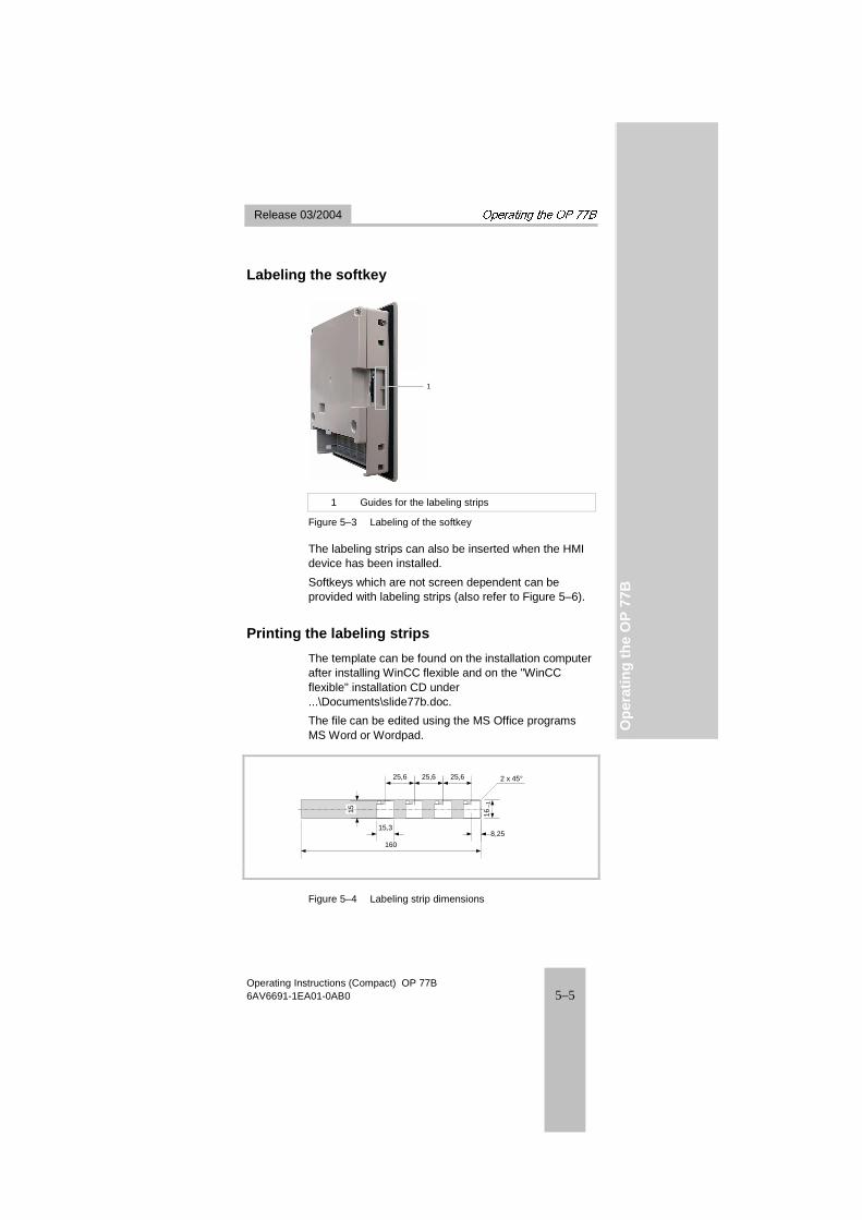
Labeling the softkey
1
1 Guides for the labeling strips
Figure 5–3 Labeling of the softkey
The labeling strips can also be inserted when the HMI device has been installed.
Softkeys which are not screen dependent can be provided with labeling strips (also refer to Figure 5–6).
Printing the labeling strips
The template can be found on the installation computer after installing WinCC flexible and on the "WinCC flexible" installation CD under ...\Documents\slide77b.doc.
The file can be edited using the MS Office programs MS Word or Wordpad.
160
15,3
15
25,6
8,25
–116
25,625,6 2 x 45°
Figure 5–4 Labeling strip dimensions

�������������������� Release 03/2004�
Operating Instructions (Compact) OP 77B 5–6 6AV6691-1EA01-0AB0
Where possible, print the labeling strips on transparent foil. This means that the LEDs on the softkeys remain visible.
��� Edit and print templates
��� Cut out labeling strips Ensure that the corners are cut according to Figure 5–4. This simplifies sliding it into the guide.
Danger Danger, high voltage
After opening the switching cabinet, parts become exposed which conduct voltage levels that could prove fatal on contact.
Switch off the power supply to the switching cabinet before opening it.
��� Remove the existing labeling strips
��� Slide the labeling strips in the guide
1
2
1 Labeling strips
2 MMC
Figure 5–5 Insert the labeling strips

��Release 03/2004� ��������������������
Operating Instructions (Compact) OP 77B 6AV6691-1EA01-0AB0 5–7
Op
erat
ing
th
e O
P 7
7B
5.3 Operating the Project
Softkeys with global function assignment
A softkey with global function assignment always triggers the same action on the HMI device or PLC regardless of the screen currently open. These actions include:
• Calling in a screen
• Printing the screen displayed
Within a screen, a softkey can only have one function assigned – either global or local. In the case of local and global functions, the local function has priority.
Softkeys with local function assignment
A softkey with a local function assignment relates to a specific screen and, thus, is only effective in the active screen.
The function of a softkey can vary from screen to screen.
The two-row softkeys are particularly suitable for implementing binary states and machine functions, as illustrated in the following screen.
OFF
ON
STOP
START
–
+
Figure 5–6 Example of two row, labeled keys

�������������������� Release 03/2004�
Operating Instructions (Compact) OP 77B 5–8 6AV6691-1EA01-0AB0
System keys
Table 5-1 Overview of control keys
Key Effect of pressing
,
The cursor keys have a repeat function.
In the case of I/O fields, selects the next field in horizontal direction.
,
In the case of I/O fields, selects the next field in vertical direction.
TAB
The following field is selected in the sequence defined in the project (Tab Order).
SHIFT
The second function of another key is released for use.
SHIFT
+
SHIFT
+
When used with the cursor keys, scroll in the selection fields; refer to Chapter 5.4.3 and 5.4.5.
SHIFT
+ TAB
The Tab Order is reversed
INSDEL
In character "String" input fields, the character at the current cursor position is deleted.
All the following characters move one position to the left.
HELP
Calls in a window containing operator notes on the selected object. Condition:
Operator notes are only available on the selected
object when the HELP
LED lights up.
Pressing ENTER
enables toggling between operator notes for a screen and an object; toggling for an I/O field for example.
ESC
• Undo
An entry can be undone by pressing this key before the
ENTER
key is pressed to confirm the input.
• Close the System Event window, if configured
• Cancel the display of an operator note to return to the previous display.
ACK
Acknowledges the alarm current displayed or marked, or all alarms in an acknowledgment group, depending on the configuration; refer to Chapter 6.2

��Release 03/2004� ��������������������
Operating Instructions (Compact) OP 77B 6AV6691-1EA01-0AB0 5–9
Op
erat
ing
th
e O
P 7
7B
Key Effect of pressing
ENTER
• The input is confirmed and applied.
• Initiates input via and
Navigation in lists
Table 5-2 Keys for navigation in lists
Key Effect of pressing
or
Selects the previous or next list item.
SHIFT
+ 9
SHIFT
+ 3
Scrolls one page forward or back to other list entries
SHIFT
+ .
HOME
SHIFT
+ 0END
Marks the first or last entry in a list

�������������������� Release 03/2004�
Operating Instructions (Compact) OP 77B 5–10 6AV6691-1EA01-0AB0
5.4 Input Within a Project
General procedure
Values are entered in the project input fields. They are transferred from there to the PLC.
Proceed as follows:
��� Open the required screen.
��� Select the required input field from the screen. Enter values of the following type in the input field according to the configuration:
– Numeric – Alphanumeric – Symbolic – Date/Time
��� Enter value
Incorrect input can be canceled by pressing ESC
. The original value is then automatically restored.
��� Confirm input with ENTER
5.4.1 Numeric values
Entering numeric values
Numeric values are entered character by character using the system keyboard. If a field already contains a value, it is fully deleted from the field after entering the first character of the new value using the numeric keypad. The value can also be modified character by character by pressing ENTER.

��Release 03/2004� ��������������������
Operating Instructions (Compact) OP 77B 6AV6691-1EA01-0AB0 5–11
Op
erat
ing
th
e O
P 7
7B
Display formats
Values can be entered in numeric input fields using the following display formats:
• Decimal
• Hexadecimal
• Binary
The input can be aligned to the left or right, depending on the configuration.
Limit value test
Limit values can be configured for tags. If the value entered exceeds a configured limit value (e.g. 55 with a limit value of 50), a system event is automatically displayed in cases where an alarm window has been configured. The value entered is not accepted and the original value reappears.
Decimal places
If a numeric input field is configured with a specific number of decimal places, additional decimal places are ignored after confirmation or too few decimal places are filed with "0".
5.4.2 Alphanumeric values
Alphanumeric values – digits and letters – are entered character by character using the system keyboard. If a field already contains a value, it is fully deleted from the field after entering the first character of the new value using the numeric keypad. The value can also be modified character by character by pressing ENTER.
If characters are required which are not available on the keypad, select them using the character set on the extended keyboard. The extended character set is available in "String" format fields.

�������������������� Release 03/2004�
Operating Instructions (Compact) OP 77B 5–12 6AV6691-1EA01-0AB0
5.4.3 Entering numeric and alphanumeric characters
Table 5-3 Overview of keys for use for entering characters
Key Effect of pressing
0END
to 9
Enter the digits 0 to 9.
,+/–
, .
HOME
Enter a comma or stop.
SHIFT
+ ,
+/–
The sign of a numeric value is changed
Press ,+/–
to toggle between the two signs.
SHIFT
+ 1
A
to
SHIFT
+ 8
F
Letters A to F can be entered
The characters in an extended character set are called in successively
All 255 character are displayed in succession.
ENTER
The input is valid.
ESC
The input is deleted.
The original value becomes valid again.

��Release 03/2004� ��������������������
Operating Instructions (Compact) OP 77B 6AV6691-1EA01-0AB0 5–13
Op
erat
ing
th
e O
P 7
7B
Example of alphanumeric input using cursor keys and numeric keypad
To enter "OP 77B", activate the selection field. If the cursor keys are used for input, press them until the required character appears. The following keyboard input is necessary:
2B
SHIFTINSDEL
ENTER
+
SHIFT +
ENTER
7E
7E
A
O
1
1
2
2
2
O
A
O P
O P
O P A
O P 7
O P A7
O P 77
O P A7 7
O P B7 7
B77PO
1 Input via the cursor keys
2 Input via the numeric keypad
Figure 5–7 Example of alphanumeric input using cursor keys and numeric keypad

�������������������� Release 03/2004�
Operating Instructions (Compact) OP 77B 5–14 6AV6691-1EA01-0AB0
5.4.4 Correcting input
Correcting input using the cursor keys
Replacing an incorrect character
Proceed as follows:
��� Press ENTER
��� Position the cursor at the character to be changed.
��� Press or until the required character appears.
��� Press ENTER
Deleting a character
Proceed as follows:
��� Press ENTER
��� Position the cursor at the character to be deleted.
��� Press INSDEL
The marked character is deleted. The remaining characters to the right of the cursor shift one position to the left.
Valid for writing aligned to the right:
The marked character is deleted. The remaining characters to the left of the cursor shift one position to the right.

��Release 03/2004� ��������������������
Operating Instructions (Compact) OP 77B 6AV6691-1EA01-0AB0 5–15
Op
erat
ing
th
e O
P 7
7B
Entering a space
Proceed as follows:
��� Press ENTER
��� Move the cursor to the position where a character is to be entered.
��� Press SHIFT
+ INSDEL
– a space is entered. The remaining characters to the right of the cursor shift one position to the right.
Valid for writing aligned to the right:
The remaining characters from the cursor shift one position to the left.
Correcting input using the numeric keypad
Replacing an incorrect character
��� Press ENTER
��� Position the cursor at the character to be changed.
��� Enter the correct character via the numeric keypad
One character too many or too few
Corrections are made as described in Section "Correcting input using the cursor keys".

�������������������� Release 03/2004�
Operating Instructions (Compact) OP 77B 5–16 6AV6691-1EA01-0AB0
5.4.5 Entering symbolic values
The work involves accepting text from a symbolic I/O field. Proceed as follows:
��� Select a symbolic I/O field
��� Activate the selection field.
Key Effect of pressing
ENTER
or
SHIFT
+
SHIFT
+
The selection field is activated containing the symbolic input configured for it.
��� Select text.
Key Effect of pressing
,
Text is scrolled in a single line list until the text searched for is found.
��� Accept or cancel the input
Key Effect of pressing
ENTER
The text selected becomes valid.
The symbolic I/O field is deactivated.
ESC
The original text becomes valid again.
The symbolic I/O field is deactivated.

��Release 03/2004� ��������������������
Operating Instructions (Compact) OP 77B 6AV6691-1EA01-0AB0 5–17
Op
erat
ing
th
e O
P 7
7B
5.4.6 Entering date and time
To enter the date and time, use the keys according to the section "Entering numeric and alphanumeric characters".
Note When entering the date and time, please note that the format is dependent on the language set.
Use the keys as described in Chapter 5.4.3 to enter the date and time.
5.5 Calling Help on a Project Operator notes can be created for the following objects during configurations with WinCC flexible ES:
• Alarms
• Screens
• I/O field
• Recipes and recipe elements
Operator notes can be configured in several languages.
The availability of an operator note is indicated by the HELP
LED when lit up. The configured operator notes
can be displayed on the HMI device by pressing HELP
.

�������������������� Release 03/2004�
Operating Instructions (Compact) OP 77B 5–18 6AV6691-1EA01-0AB0
5.6 Logging On and Off
General information
Standard groups in the security system are:
• Administrator
• User
Other groups can be configured. Each group is assigned certain user rights. Each user is assigned to one of these groups, i.e. users within a group have the same operating rights. Each user is assigned a password.
Login dialog
When a user calls a function which is protected and has not been assigned the necessary user rights, the Logon dialog appears.
User:
OK
Password:
Cancel
Figure 5–8 Example of a Logon dialog
��� Enter the user name and password – refer to Chapter 5.4.3 for the keys.
Note Characters entered for the password are always represented by "∗ ". Characters entered via the cursor keys remain visible until another character is entered or the input is confirmed with the ENTER.

��Release 03/2004� ��������������������
Operating Instructions (Compact) OP 77B 6AV6691-1EA01-0AB0 5–19
Op
erat
ing
th
e O
P 7
7B
��� Select OK
��� Press ENTER
to confirm If the user has the necessary user rights for a selected operating element, it can be operated. Otherwise, an alarm appears indicating the user does not have the necessary rights.
Note In the case of an operating element assigned operating rights, a log on is necessary. This is obsoleted, however, on exceeding the logoff time – refer to Figure 5-13.
5.7 User Administration in a Project There are three groups which can manage the users and their assigned entries:
• the administrator
During configuration, the administrator is assigned unlimited user rights.
• the operator (user)
• the user with unrestricted user rights.
These groups of people result from the assignment of user rights during configuration.
Administrator
Operator
Runtime User 1
Figure 5–9 Example of a user display

�������������������� Release 03/2004�
Operating Instructions (Compact) OP 77B 5–20 6AV6691-1EA01-0AB0
In this case, as indicated in the example in Figure 5–9, the administrator and two users are shown. The administrator may change his own entries and those of the other users:
– User name – Password – Group assignment – Log off time
In addition, further users can be set up. The empty bottom line is available for the setup.
• If a user cannot log on as "Administrator" but only as a user, only that entry is displayed, e.g. "Operator".
In this case, no unrestricted user rights have been assigned.
Only the following entries can then be changed for that user
– Password and – Logoff time.
• However, it is possible for a user to modify the entry
of another user. A condition for this is that the user rights include the user rights of the other users. Entries which can be modified include:
– User name – Password – Group assignment – Log off time

��Release 03/2004� ��������������������
Operating Instructions (Compact) OP 77B 6AV6691-1EA01-0AB0 5–21
Op
erat
ing
th
e O
P 7
7B
Table 5-4 Keys for navigation in lists
Key Effect of pressing
,
Selects the previous or next user.
SHIFT
+ 9
SHIFT
+ 3
Scrolls one page up or down to other users.
SHIFT
+ .
HOME
SHIFT
+ 0END
Selects the first or last user.
Limit values for user, password and user displays
Characters
Length of user name, maximum 40
Length of password, minimum 3
Length of password, maximum 24
Entry in the user display, maximum 50
5.7.1 Log on user
Proceed as follows:
��� Select the empty line in the dialog – refer to Figure 5–9
��� Press ENTER
Note The following Logon dialog only appears when the user has still not been logged on as a user. The dialog also appears when the user logs on as Administrator without the necessary user rights in order to create a new user.
The Logon dialog opens.

�������������������� Release 03/2004�
Operating Instructions (Compact) OP 77B 5–22 6AV6691-1EA01-0AB0
��� Enter the user and password.
��� Confirm with OK The dialogs necessary to set up a user then appear.
After having logged on, you ca carry out the following according to your user rights:
• Change the password
• Create a user
5.7.2 Setting up a user
The following dialogs appear after entering the user and password:
User:
OK Cancel
|
Figure 5-10 Example of a User dialog
Proceed as follows:
��� Enter a user
��� Confirm with OK The following dialog appears:
Password:
OK Cancel
|
Figure 5-11 Example of a Password dialog
Note The password is only legible once in plain text – when it is assigned in the Password dialog.
On entering a password at a later date, the characters entered are represented by .
��� Enter the password

��Release 03/2004� ��������������������
Operating Instructions (Compact) OP 77B 6AV6691-1EA01-0AB0 5–23
Op
erat
ing
th
e O
P 7
7B
��� Confirm with OK The following dialog appears:
Group:
OK Cancel
Operators
Figure 5-12 Example of a Group dialog
��� From the list of available groups, select the one containing the user rights to be assigned to the new user.
Make the selection using SHIFT
+ or or
using ENTER
and then or .
Logoff time:
OK Cancel
5
Figure 5-13 Example of a Logoff Time dialog
The logoff time is defined in minutes. 5 minutes are entered as the default value.
��� Select the value depending on the respective operating situation.
�� Confirm with OK The user display appears containing the new user, refer to Figure 5–9.

�������������������� Release 03/2004�
Operating Instructions (Compact) OP 77B 5–24 6AV6691-1EA01-0AB0
5.7.3 Changing passwords
The following dialogs appear after entering the user and password:
User:
OK Cancel
User 1
Figure 5-14 Example of a Password dialog
Proceed as follows:
��� Enter a user
��� Confirm with OK The following dialog appears:
Password:
OK Cancel
Password
Figure 5-15 Example of a Password dialog
��� Enter the password
��� Confirm with OK Confirm the two subsequent dialogs. The new password becomes valid.
5.7.4 Deleting a user name
When a user is deleted, the password is deleted from the User display. A condition for deleting users is the assignment of administrator rights.
There are two methods of deleting a user:
• Select the user name in the User display and press INSDEL .
• Delete all the characters in the user name input dialog and confirm by clicking OK.

��Release 03/2004� ����������� �!��
Operating Instructions (Compact) OP 77B 6AV6691-1EA01-0AB0 6–1
Rec
ipes
an
d A
larm
s
6 Recipes and Alarms
6.1 Operating Recipes
Terminology
Recipe
A recipe is comprised of several tags which define the data structure of as data record.
Data record
A data record contains the values of a recipe.
Recipe entry
A recipe element consists of an entry name and a value. The names, assigned to the tags, are referred to an element names.
Single recipe views
The Recipe view is a configurable object in the recipes, data records and recipe elements displayed in lists. These are described below.
6

����������� �!�� �������� �����
Operating Instructions (Compact) OP 77B 6–2 6AV6691-1EA01-0AB0
Recipe list
The recipes configured are displayed as a recipe list. A recipe list can appear as follows, for example:
1 Grapefruit 2 Lemon 3 Orange 4 Apple
Figure 6–1 Example of a recipe list
Table 6-1 Overview of keys available
Key Effect of pressing
SHIFT
+
INSDEL
Creates a new data record.
ENTER
Opens the data record list of the selected recipe.
HELP
Calls in a window containing operator notes on the selected object – refer to Table 5-1.
Opens the menu
Further keys used for navigation are explained in Section "Navigation in lists". This also applies to operating in recipes.

��Release 03/2004� ����������� �!��
Operating Instructions (Compact) OP 77B 6AV6691-1EA01-0AB0 6–3
Rec
ipes
an
d A
larm
s
Data record list – Data records of a recipe
1 Juice 2 Drink 3 Nectar
Figure 6–2 Example of a data record list
Table 6-2 Overview of keys used in data record lists
Key Effect of pressing
SHIFT
+
INSDEL
Creates a new data record.
ENTER
Opens the entry list of the selected data record.
ESC
The recipe list is displayed again.
Note
When the first data record has been selected and is pressed, the associated recipe name is displayed.

����������� �!�� �������� �����
Operating Instructions (Compact) OP 77B 6–4 6AV6691-1EA01-0AB0
Element list – data record values
The element list can be used to edit data record values.
l Orange l Water kg Sugar g Aroma
90 10 1.5 200
1
3 2
1 Data record
2 Menu
3 Element name
Figure 6–3 Example of an element list
The sequence of columns for element names and values can be configured.
Table 6-3 Overview of keys available for use
Key Effect of pressing
ESC
The data record list is displayed again.
HELP
Calls in a window containing operator notes on the selected object – refer to Table 5-1.
Note
When the first element has been selected and is pressed, the associated data record and recipe name is displayed.
Proceed as follows to edit a value:
��� Select element name The entries possible are dependent on the tag type. If a text list has been configured in a recipe element, symbolic values can also be entered.
��� Enter value
��� Apply the entry or cancel it

��Release 03/2004� ����������� �!��
Operating Instructions (Compact) OP 77B 6AV6691-1EA01-0AB0 6–5
Rec
ipes
an
d A
larm
s
Menu
A menu is available for quick access to the permitted operating procedures in recipes, data records and element lists.
Menu button Effect of pressing
Call in the menu
Alternatively to using , the menu can be called in with
.
The menu items which can be configured can be determined from Table 6-4.
Configurable menu items in the Recipe view
The following table indicates which menu items are available in the three lists. Some menu items in the following table can also be called in via the system keys.
����������� �!�� �������� �����
Operating Instructions (Compact) OP 77B 6–6 6AV6691-1EA01-0AB0
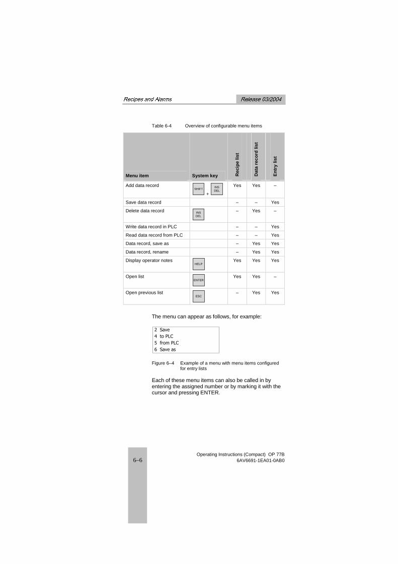
Table 6-4 Overview of configurable menu items
Menu item System key Rec
ipe
list
Dat
a re
cord
list
En
try
list
Add data record SHIFT
+
INSDEL
Yes Yes –
Save data record – – Yes
Delete data record INSDEL
– Yes –
Write data record in PLC – – Yes
Read data record from PLC – – Yes
Data record, save as – Yes Yes
Data record, rename – Yes Yes
Display operator notes HELP
Yes Yes Yes
Open list ENTER
Yes Yes –
Open previous list ESC
– Yes Yes
The menu can appear as follows, for example:
2 Save 4 to PLC 5 from PLC 6 Save as
Figure 6–4 Example of a menu with menu items configured for entry lists
Each of these menu items can also be called in by entering the assigned number or by marking it with the cursor and pressing ENTER.

��Release 03/2004� ����������� �!��
Operating Instructions (Compact) OP 77B 6AV6691-1EA01-0AB0 6–7
Rec
ipes
an
d A
larm
s
Table 6-5 Overview of keys for use in a menu for a Recipe view
Key Effect of pressing
1A
to 9
Calls in the assigned menu item.
ENTER
Triggers the menu item selected with the cursor.
ESC
Displays the previously selected list.
Example
Using the Save Data Record menu item – refer to Figure 6–4.
Proceed as follows:
With cursor key input
��� Select Save Data Record with the cursor key.
��� Confirm the selection with ENTER. The data record is saved and the entry list reappears.
With numeric input
��� Enter "2". The data record is saved and the entry list reappears.

����������� �!�� �������� �����
Operating Instructions (Compact) OP 77B 6–8 6AV6691-1EA01-0AB0
6.2 Operating Alarms
Alarm classes
The alarm classes can exist in a project:
• User-defined alarms
A user-defined alarm can be assigned to one of the following alarm classes:
– Fault
Alarms in this category must always be acknowledged.
– Operation – User-defined alarm classes
The properties of this alarm class are defined during configuration.
• System events
A system event is assigned to the "System" event category.
The related alarms consist of static text. They can also contain tags. It is possible to configure an alarm text to flash.
A maximum of 80 characters per alarm are possible.
"Fault" alarm class
The occurrence of an alarm of the alarm class "Fault" is indicated by the flashing "alarm indicator" LED:
Figure 6–5 "Alarm indicator" LED
The "alarm indicator" LED
• is off when no alarms of the "Fault" alarm class are queued,
• flashes when an alarm of the "Fault" alarm class has been received but not acknowledged and
• only lights up if acknowledged alarms of the "Fault" alarm class are present.

��Release 03/2004� ����������� �!��
Operating Instructions (Compact) OP 77B 6AV6691-1EA01-0AB0 6–9
Rec
ipes
an
d A
larm
s
Alarm view
156 12:05:49 AlarmEngine 23 to hot
Figure 6–6 Alarm view for "Fault" alarm class
It is possible to configure:
• The number of lines per alarm.
• Number of visible lines
Table 6-6 Overview of keys used in Alarm views
Key Effect of pressing
ACK
Acknowledges the alarms which have arrived.
HELP
Calls in the operator notes on the selected alarm.
Further keys for navigation purposes are explained in Table 5-1.
The keys displayed in the table are valid for all alarm classes.
Edit alarm
Pressing ENTER
triggers the function assigned to the "Edit" event in respect of a selected alarm.

����������� �!�� �������� �����
Operating Instructions (Compact) OP 77B 6–10 6AV6691-1EA01-0AB0

��Release 03/2004� ����"�
Operating Instructions (Compact) OP 77B 6AV6691-1EA01-0AB0 7–1
Ind
ex
7 Index
A
Accessory kit 1–3 Alarm class
Fault 6–8 Alarm classes 6–8
User-defined 6–8 Alarm view 6–9 Alarms 6–1
User-defined 6–8 Alphanumeric input
Via the cursor keys 5–14 Via the numeric keypad
5–14
B
Bottom view 1–2
C
Cable cross-section 4–8 Configuring
Interface 4–4 Configuring the interface
4–4 Connecting
Configuration computer 4–6
OP 77B 4–1 Periphery 4–7 PLC 4–3 Potential equalization
line 4–2 Power supply 4–8 Terminal block 4–8
Connecting peripheral equipment 4–7
Connecting the configuration computer 4–6
Connecting the PLC 4–3 Connecting the potential
equalization 4–2 Connecting the terminal
block 4–8 Connection configuration
Configuration computer 4–6
Periphery 4–7 PLC 4–3 Potential equalization
line 4–2 Power supply 4–8
Connection sequence 4–1 Connections, electrical 4–1 Control keys 5–9 Correcting
Input 5–15 Cross-section
connection cables 4–8
D
Data record list 6–3 Date 5–18 Decimal places 5–12 Deleting a user name 5–25 DIL switch 4–5 Display 2–1 Display formats 5–12
7

����"� Release 03/2004�
Operating Instructions (Compact) OP 77B 7–2 6AV6691-1EA01-0AB0
E
Edit Alarm 6–9
Edit alarm 6–9 Element list 6–4 EMC Guidelines 3–1 Entering
Alphanumeric characters 5–13
Date and time 5–18 Numeric characters
5–13 Numeric values 5–11 Symbolic values 5–17
Example Alphanumeric input via
the cursor keys 5–14 Alphanumeric input via
the numeric keypad 5–14
F
Front view 1–1
G
Guidelines EMC 3–1
H
Help on a project 5–18 Housing 2–1
I
IF 1A 1–6 IF 1B 1–5 Indicators 5–1 Input
Correcting 5–15 Input in a project 5–11 Installation
OP 77B 3–1 Installation cut-out 3–3 Installation positions 3–2 Interfaces 1–5
K
Keyboard 2–1
L
Labeling 5–6 Labeling strips 1–4, 5–6 Limit value test 5–12 Limit values
For users, passwords, user displays 5–22
Log off 5–19 Log on 5–19
User 5–22 Login dialog 5–19
M
Memory 2–2 Memory card 1–3
Eject 5–5 Using 5–4
Menu 6–5 Menu items
Configurable 6–5 Miscellaneous 1–4
N
Navigation Loader menu 4–11
Navigation in lists 5–10
O
OP 77B Connecting 4–1 Installation 3–1 Operating 5–1
Operating Alarms 6–8 OP 77B 5–1 Project 5–8 Recipes 6–1
Operating elements Front side 5–1 Other 5–3
Operating recipes 6–1 Operating system
��Release 03/2004� ����"�
Operating Instructions (Compact) OP 77B 6AV6691-1EA01-0AB0 7–3
Ind
ex
Load 4–10 Options 1–3 Overview 1–1
P
Power supply 1–5, 2–2 Connecting 4–8
print Labeling strips 5–6
Project Help 5–18 Input 5–11 Operating 5–8 User administration
5–20
R
Recipe list 6–2 Recipe views
Menu 6–5 Recipes 6–1 Reverse battery protection
4–8 RS 232 1–6 RS 422 1–5 RS 485 1–5
S
Scaled drawings 1–4
Side view 1–2 Softkeys 2–1, 5–3, 5–8
global 5–8 labeling 5–6 local 5–8
Switch settings 4–5 Switching on 4–9, 4–10 System keys 2–1, 5–3
T
Technical data 2–1 Terminology
Recipe views 6–1 Time 5–18 Type of fixation 3–3
U
USB 1–6 User
Log on 5–22 User administration 5–20
V
Values alphanumeric 5–12 numeric 5–11 Symbolic 5–17

����"� Release 03/2004�
Operating Instructions (Compact) OP 77B 7–4 6AV6691-1EA01-0AB0