Embed Size (px)
Citation preview

SIM University 2011

Visual Display System Specifications, and how we test themp y y p
October 20, 2011
Justin K. KnaplundDirector of Engineering, FlightSafety International - Displays
2

Testing Specifications for Visual Display SystemsField of View: Instantaneous versus Total Testing Location• Field of View: Instantaneous versus Total, Testing Location
• Contrast (as Affected by Mirror Reflections)
SIM UniversityOctober 20, 20113

Field of View: Instantaneous versus Total• Instantaneous FOV is what can be measured from a fixed point (either the Design Eye• Instantaneous FOV is what can be measured from a fixed point (either the Design Eye
Point or Pilot Eye Point) using a theodolite to measure the extents of the mirrors.• Total FOV is what can be viewed using head movement from anywhere within the viewing
volume. It is generally understood to be the usable view of the Image on the Back or Front Projection ScreenProjection Screen.
SIM UniversityOctober 20, 20114

Field of View: IFOV versus TFOV from DEP
SIM UniversityOctober 20, 20115

Field of View: IFOV versus TFOV from Left PEP
SIM UniversityOctober 20, 20116

How is FOV specified? Case 1: 200ºx 60ºVIP Helicopter Program circa 2007 Originall designed for 220°VIP Helicopter Program, circa 2007. Originally designed for 220 x 60° in a container, was reduced to 200°x 60° for fit.Appendix A of the specification read “The minimum Total Field-Of-
° °View measured from the pilot’s eye point shall be 200°x 60°.”
SIM UniversityOctober 20, 20117

Case 1: 200ºx 60º test method
Acceptance Test Procedure:Position the Laser Theodolite at the Pilot’s (right) Eye Point. Horizontal FOV: Using the theodolite, measure from a 0º Azimuth
i t tb d t th t d f thpoint outboard to the extreme edge of the mirror at 0º Elevation. Vertical FOV: Using the theodolite, measure the uplook and downlook angles for 0º Az, as well 30º, 60º and 90º Azimuths.Added FSI Note: Some areas of the TFOVAdded FSI Note: Some areas of the TFOV as depicted by the BP Screen may be obscured by the BP Screen itself. Note that the full 60º VFOV requirement should be met between +10º and +80º Azimuth.
SIM UniversityOctober 20, 20118

FOV Case 2: USCG 220ºx 60ºCustomer Specification: “The display field of regard distribution as measured from theCustomer Specification: The display field of regard distribution as measured from the visual system design eyepoint and except as limited by the aircraft structure shall be 220° azimuth by 60 total° elevation. The 60-degree vertical field of view is divided as +20° (up) to –40° (down).”
SIM UniversityOctober 20, 20119

FOV Case 2: Test methodAcceptance Test Procedure:Acceptance Test Procedure: Position the laser theodolite at the design eye point. Horizontal FOV: Using the theodolite, measure from a 0º Azimuth point outboard to the extreme left and right edges of the mirror at 0º Elevation Vertical FOV: Visually confirm0 Elevation. Vertical FOV: Visually confirm that +20º elevation points as rendered by the IG and projectors (for uplook) and -40º elevation of the mirror’s bottom edge (for downlook) are visible from the DEP per the Aitoff by using either the laser theodolite or by direct yobservation of the points rendered by the IG. Added FSI Note: Some areas of the TFOV as depicted by the BP Screen will be obscured by the cockpit and/or BP Screen. Since the laser will be obscured for uplook angles above about 16° straight ahead, uplook points will require head motion to observe the Spherical Grid on the BP screen. The vertical FOV requirement is assumed to be met when the FOV is satisfied anywhere
SIM UniversityOctober 20, 201110
assumed to be met when the FOV is satisfied anywhere.

FOV Case 3: Marine Helicopter, HFOV SpecInitial Customer Specification: “The main OTWInitial Customer Specification: The main OTW shall provide a continuous horizontal FOV of no less than 220°”
Final Customer Specification: “The FOV specified for the right side half is relative to thespecified for the right-side half is relative to the pilot eyepoint position. The right-side half of the Main OTW display shall provide a continuous horizontal FOV of 110°, spanning from the zero azimuth reference (i.e. dead ahead of co-pilot) to 110° right of the zero reference and apilot) to 110 right of the zero reference and a continuous vertical FOV of 60°, as measured from anywhere within the corresponding viewing volume centered at the pilot eyepoint position.” [Repeat for co-pilot/Left side]
SIM UniversityOctober 20, 201111

FOV Case 3: Marine Helicopter, VFOV SpecInitial Customer Specification: “The vertical fieldInitial Customer Specification: The vertical field of view shall be a combination of several distinct display subsystems: the main OTW, chin windows, and side windows ground views, and shall present an overall vertical field of view of no less than 70°, with the upward field ofof no less than 70 , with the upward field of view of 20° above the horizon. The area corresponding to straight ahead shall have a vertical FOV of 20° up and no less than 20°down over a heading range of ±20° heading.”
Final Customer Specification: “…and a continuous vertical FOV of 60°, as measured from anywhere within the corresponding viewing volume centered at the pilot [co-pilot] eyepoint position “eyepoint position.
SIM UniversityOctober 20, 201112

FOV Case 3: Test MethodAcceptance Test Procedure:Acceptance Test Procedure: •Position the observer at the pilot’s eye point. •Horizontal FOV: Observe the displayed image from 0º Azimuth outboard to the extreme edge of the mirror and note the horizontal FOV displayed by the spherical pattern. •Vertical FOV: Position the observer in the vicinity of the eye point to provide a clear, unobstructed view of the BP screen and note the vertical FOV displayed, repositioning as necessary to provide a clear, unobstructed view of the upper and lower portions of the BP Screen. *•*Note: Some areas of the TFOV as depicted by the BP Screen may be obscured by the BP Screen itself, requiring the observer to reposition in order to have a clear, unobstructed view of the image. FSD Note:Visually observing the spherical test pattern as displayed on the BP screen for elevations between +20º and -40º, and azimuths from 0º to 110º outboard from any point within the viewing volume shall meet the FOV requirementand azimuths from 0º to 110º outboard from any point within the viewing volume shall meet the FOV requirement. Verification of the spherical test pattern accuracy is accomplished during the test for Total Geometric Distortion section this document.
SIM UniversityOctober 20, 201113
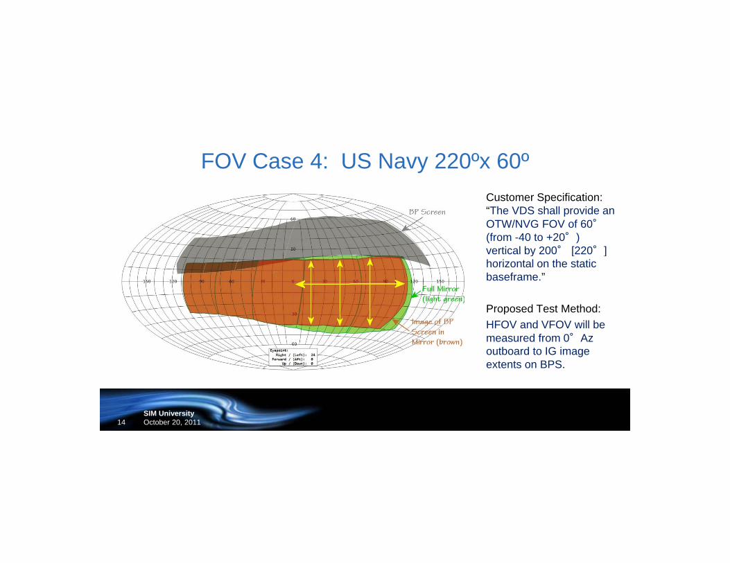
FOV Case 4: US Navy 220ºx 60ºCustomer Specification: “The VDS shall provide an OTW/NVG FOV of 60°(from -40 to +20°) vertical by 200° [220°]vertical by 200 [220 ] horizontal on the static baseframe.”
Proposed Test Method:Proposed Test Method:HFOV and VFOV will be measured from 0°Az outboard to IG image extents on BPS.
SIM UniversityOctober 20, 201114

Contrast SpecificationCase 1 & Case 2: “Contrast ratio for OTW imagery shall be no less than 10:1 for the Center channel display. The average contrast ratio for each of the other channels shall not vary from the center channel's average measured value by more than 25 percent. All channels shall be on during this test. Contrast ratio shall be tested using a checkerboard test pattern with all display channels illuminated with the test pattern simultaneously All test patterns must provide at least 16 squares per displaywith the test pattern simultaneously. All test patterns must provide at least 16 squares per display channel with 50 percent of the squares at the specified maximum luminance. The test pattern shall be generated using the same image processing methods used to generate training scenes.”
Case 3: ”Contrast not less than 8:1”; required both positive & negative checkerboard patterns; noCase 3: Contrast not less than 8:1 ; required both positive & negative checkerboard patterns; no requirement to balance contrast between channels
Case 4: Same as Case 3, Contrast > 10:1
SIM UniversityOctober 20, 201115

Collimated Contrast Challenge: Window Shade Effect
SIM UniversityOctober 20, 201116

Window Shade Sequence: Nose Low
SIM UniversityOctober 20, 201117

Window Shade Sequence : Nose High
SIM UniversityOctober 20, 201118

Contrast Testing
Note: Results shown are for a single projector on a 9’R, 40° VFOV mirror
SIM UniversityOctober 20, 201119

Window Shade VariablesThe Window Shade Effect is independent of:
•Mirror Substrate; Glass or Mylar•Front or Back Projection Screen•Projector Lumens or Technology•Projector Location or Pitch angle
The Window Shade Effect is dependent on:•Display FOV: Worse with larger vertical and horizontal FOV; larger mirror “collector”Display FOV: Worse with larger vertical and horizontal FOV; larger mirror collector•Number of Projectors: More projectors results in more light scatter within optics •Scene Contrast: High Contrast IG Imagery (very bright sky, very dark land or water) makes the Window Shade effect more noticeable
SIM UniversityOctober 20, 201120

Effect of Scene Contrast
Conclusion: Reduce Scene Contrast to reduce Window Shade Effect
SIM UniversityOctober 20, 201121
Conclusion: Reduce Scene Contrast to reduce Window Shade Effect

SIM University 2011
Thank you.Thank you.Questions?