Embed Size (px)
Citation preview

. .
Silica Aerogel Captures Cosmic Dust Intact
Peter TsouJet Propulsion Laboratory, California Imtitute OS TechnologyPasadena California 9110S-8099
The rnesostructure of silica aerogel resembles strings of grapes, ranging in siT.c from 10A to 100~. This fine me-sostructure transmits nearly 90% of incident light in the visible, while providing sufticicntly gentle dissipation of thekinetic energy of hypu-velocity ecsmic dust particles to permit their intact capture. Wc introduced silica aerogel in
1987 as a capture medium to take advantage of its low density, firrc mcsostructurc and most importantly, its transpar-ency, allowing optical location of captured micron sized particles. Without this feature., locating such captured parti-cles in an opaque medium, e.g., polymer foams, is nearly impossible. The capture of hypervelocity particles has beenextensively simulated in the laboratory. At the time of this symposium, more than 2.4 m2 of 20 mg/ml silica aerogclwill have been flown on Space Shuttle (STS-47, STS-57, STS-60, STS-64 and STS-68). This space demonstration ofcapturing hypervcloeity particles ushers in a new, simple avenue to science in capturing intact cosmic dust from space.Since our introduction of aerogel for intact capture of cosmic dust, many useful features unique to aerogcl have bccrridcntitied. In the current era of a faster, cheaper and better political environment, it is obviously very advantageous toachieve great scicncc by a simple and low-cost approach - to capture and return extraterrestrial samples passively in aflyby rather than robotically or by the landing of astronauts.
1. Introduction
Comets are spectacular solar system bodiw.They appear to be well-preserved relics of thepreplanetary material that accreted in the outerfringes of the solar nebula. These small andprimitive cometary bodies are ice-rich and havebeen preserved by remaining deeply frozen inspace. They have survived for most of the life-time of the solar system by residing in the Oortcometary cloud some fifty thousand astronomicalunits from the Sun, The bulk of cosmic dust islikely to be either cometary or asteroidal inorigin, with some even of interstellar origin andshould constitute a unique repository of informa-tion concerning the formation and subsequentprocessing history of the condensed stellar nebulawhich became our solar system, Thus, the studyof cosmic dust is important and may prove to bethe rosetta to understanding the formation andsubsequent processing of the solar system andpossibly that of life, as well [1].
One of the major goals of planetary science is thedetailed laboratory analysis of extraterrestrialsamples [2], from a specific body with knownhistory. Sample return from most extraterrestrialbodies is usually considered complex and costlyand is only considered as a follow-on to a se-quence of reconnaissance missions. It is possi-
ble, however, to collect cosmic dust left by acometary coma or aweroid collisions and return itto Earlh for detailed laboratory study. Thesetypes of space exploration missions can be donewithin a decade, at relatively low cost by highlysimplified flyby missions.
However, planetary orbital motions dictate thatcosmic particles approach spacecraft at relativespeeds of the order of tens of kn~/s. It was notobvious at first that these hypervelocity particlescould be captured intact without melting orvaporization. Worse yet, would be to havecaptured the cosmic dust but not be able to locateit in a capture medium. LJnless the dust particleswere captured in a transparent medium such asaerogel, they would be almost impossible to find,since these extraterrestrial dust of interest areextremely fine, ranging in size from 0.1 pm to100 pm in diameter. A typical cosmic dustparticle captured in the stratosphere is shown inFigure 1.
This papct traces our development of the intactcapture technology that enables intact capture ofcosmic dust at hypervelocities, a result thatrevolutionized the cosmic dust community [3].Our second contribution to the dust community isthe introduction of silica aerogel [4], which hasbeen adopted as the new standard capture
.
medium for cosmic dust collection. Results ofactual space captures of hypervelocity particlesare presented. Then, the unique features of silicaaerogel, providing the rationale for this applica-tion of cosmic dust collection, are explored.
Figure 1. Stratospheric Cosmic Dust
2. intact Capture Technique
Extraterrestrial material has intrigued planetaryscientists for a long time. Large chunks ofmeteorites have been displayed in museums andcut open for chemical, physical, isotopic andbiogenic analyses. For small micrometeoritefragments, scientists have combal crater vicini-tim and ocean floors and melted tons of ice insearch of extraterrestrial material. Only with theadvent of space flights, did the capturing ofparticles in space begin.
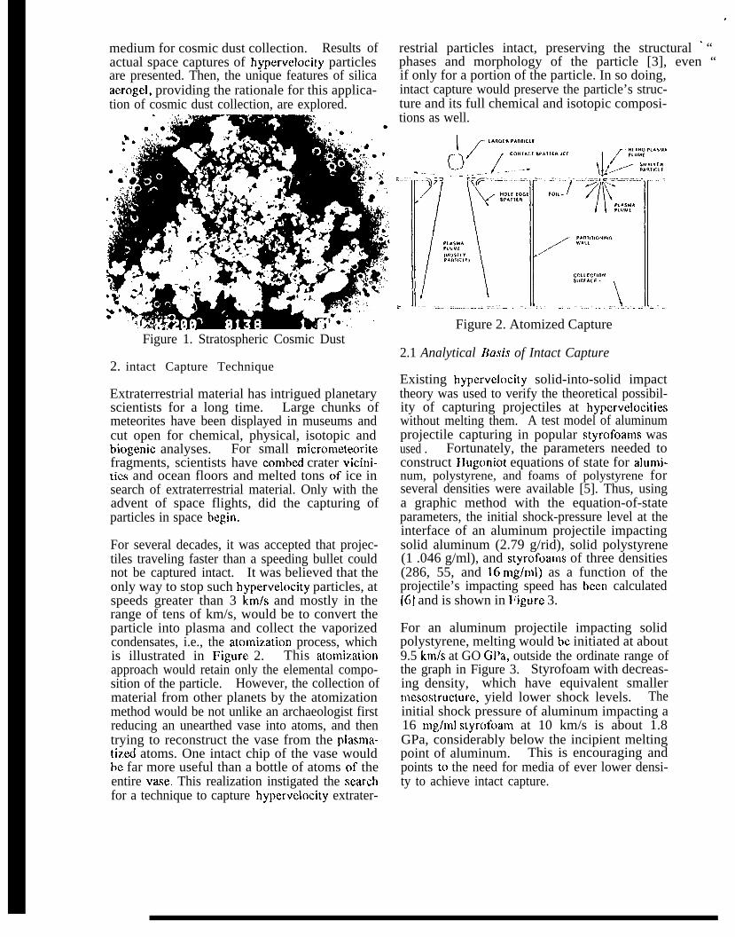
For several decades, it was accepted that projec-tiles traveling faster than a speeding bullet couldnot be captured intact. It was believed that theonly way to stop such hypervelocity particles, atspeeds greater than 3 kn~/s and mostly in therange of tens of km/s, would be to convert theparticle into plasma and collect the vaporizedcondensates, i.e., the atomization process, whichis illustrated in Figure 2. This atomii=.ationapproach would retain only the elemental compo-sition of the particle. However, the collection ofmaterial from other planets by the atomizationmethod would be not unlike an archaeologist firstreducing an unearthed vase into atoms, and thentrying to reconstruct the vase from the plasn~a-timi atoms. One intact chip of the vase wouldbe far more useful than a bottle of atoms of theentire vase. This realization instigated the searchfor a technique to capture hypervelocity extrater-
restrial particles intact, preserving the structural ‘ “phases and morphology of the particle [3], even “if only for a portion of the particle. In so doing,intact capture would preserve the particle’s struc-ture and its full chemical and isotopic composi-tions as well.
Figure 2. Atomized Capture
2.1 Analytical Rasis of Intact Capture
Existing hypervelocity solid-into-solid impacttheory was used to verify the theoretical possibil-ity of capturing projectiles at hypervelocitiwwithout melting them. A test model of aluminumprojectile capturing in popular styrofoams wasused . Fortunately, the parameters needed toconstruct Hugoniot equations of state for ahmli-num, polystyrene, and foams of polystyrene forseveral densities were available [5]. Thus, usinga graphic method with the equation-of-stateparameters, the initial shock-pressure level at theinterface of an aluminum projectile impactingsolid aluminum (2.79 g/rid), solid polystyrene(1 .046 g/ml), and styrofoams of three densities(286, 55, and 16 mg/nd) as a function of theprojectile’s impacting speed has been calculated[6] and is shown in Figure 3.
For an aluminum projectile impacting solidpolystyrene, melting would be initiated at about9.5 kn~/s at GO GPa, outside the ordinate range ofthe graph in Figure 3. Styrofoam with decreas-ing density, which have equivalent smallermesostructure, yield lower shock levels. Theinitial shock pressure of aluminum impacting a16 mg/nd styrofoam at 10 km/s is about 1.8GPa, considerably below the incipient meltingpoint of aluminum. This is encouraging andpoints to the need for media of ever lower densi-ty to achieve intact capture.

25
--- 1 ‘1Ps
30
1 /“---” / /, -- - ------- . . _..
Al [2 79 g/n)l]
1 /
1046 g/nil]
:0 2 0
F’S [.286 g/ml]/
/lL44 . . . ..-Ps [ 053 g/ml]~/---’”-----______ PS [ 016 g/r!!l]
. . - . - - - - ’ - - - - ___ .—-— -—..—. ..-.. — . . .. -1 1 -
0 2 4 6 8 10
IMf’ACTING SPEED [krn\s]
Figure 3. Shock Pressure of Aluminum impacting Polystyrene
2.2 Intact Capture i%chnology
The intact capture technique uses appropriatematerial to reduce the energy of hypervelocityparticles gradually in order not to vaporize ormelt the particles. It is even more attractivesince it is accomplished passively, as illustratedin Figure 4. A passive technique does not re-quire precision pointing, mechanisms to warmup, or devices to obtain incident speed, etc.Passive capture is simple; simplicity renders itelegant. After a decade of effort, the develop-ment of a collection technique suitable for intactcapture of hypervelocity particles has beensuccessfully demonstrated by the capture intact of0.1 pm sized iron particle at 22 km/s [7] underlaboratory simulation. Several space flights haveprovided definite proof of intact capture [8].This technology will enable comet coma samplereturn missions or an Earth orbital cosmic dustcollection mission.
y
Figure 4,
2.3 Laboratory Development
In 1983, initial laboratory experiments were
performed with 3.2-mm-dianleter aluminumprojectiles impacting expanded polystyrene foamof 18 n~g/ml density at about 6 kn~/s usingNASA Ames’ vertical two-stage light-gas gun[3]. This resulted in the startling discovery thatmore than 75% of the original projectile masswas captured. Even more encouraging, theprojectile was in one piece; there was no spalla-tion, and the projectile looked liked the originalshiny sphere, except for erosion on the frontsurface. It was intact! Subsequently, to generatea good database on intact capture, systematic andextensive simulation experiments were performedwith the two-stage light-gas gun, plasma draggun and electrostatic accelerator [9]. The light-gas gun simulation experiments consisted oflaunching projectiles at known speeds withknown mass and integrity into various capturemedia in vacuum and at room temperature. Thecapturcxl projectiles were then characterized bymeasuring the amounts of mass recovery, peri-meter profiles, and surface erosion featur&, ‘Thecapture media were examined for track din~en-sions, mass loss and surface composition.Methods of analysis included optical microscopy,scanning electron microscopy and
‘ — . - - - ’ tometry.
To assess the effects of projectileIntact Capture experiments with projectile sizes
x-ray diffrac-
si7.e, selectedranging from

0.1 pm to 6.35 mm were performed. To bettercharacterize the influence of projectile materialon intact capture, iron, copper, lead, glass,geological rocks, and even actual lunar sandwere also used [10]. To investigate the nle-sostructural effects of capture media, polymerfoams, films, fibers, microsphere, and highdensity g~s were tested. Many polymer foams,including polystyrene, polyurethane, polyethy-lene, and polyamide, were tested with densiti~sfrom 9 to 100 mg/ml. Thus far, the highestintact mass recovery in the 6 km/s range hasbeen obtained using foams made from polystyr-ene with extremely fine mesostructure [11].
2.4 Eflcctivc Capture Media
As more hypervelocity intact capturing experi-ments were performed, a clear set of capturemedia material properties producing good intactcapture results began to emerge. First, thecapture media need to be extremely underdense,the hulk density considerable less than the parentmaterial. However, we have shown that intactrecovery does not follow the reduction of capturemedia’s density indefinitely. In fact, below athreshold of low densities, the mesostructure ofthe capture medium dominates the effectivenessof intact capture [12,13]. That is to say, a cap-ture medium with considerably lower bulk densi-ty produces less intact capture than one withhigher bulk density, but with the desirable nle-sostructure. This is demonstrated in Figure 5 forvarious mesostructures of polystyrene f~am
. ‘\‘), :.
?.,,},!,!, r,, ,, , 0,,” U..,,...,
\
.“
I 2 3 4 5 a
JNIIIAL PKOJFCIILE SI)F;F,D [k,,, /s]
Figure 5. Capture Efficiency vs Density
Since our objective is the development of anintact capture technique for acquiring cosmicdust in the 0.1 ~m to 100 pm range, the ability tolocate and remove captured particles is nearly as
I
I
0
imporlant as their intactfinding a captured particlemedium can be equivalentLocating micrometer sized
capture itself. Not ‘ ‘in an opaque capture .
to no capture at all.particles on a surface
is difficult enough for a large collection surfacearea; finding such a particle in an opaque solidcan be a monumental task. Polystyrene foam ismost effective in intact capture, but it is opaque.Since the ultimate objective is to extract andanalyze the capture of pm sized cosmic particles,the effectiveness of an intact capture mediummust be determined not only by the efficiency ofintact capture but also on the extractability ofsmall particles.
3. Ncw Capture Media
The search for a better intact capture mediumfocused on low density, fine mesostructure andtransparent media. From earl y 1986, silicafoam, metallic smoke, water glass, and otherexotic laboratory novelties were explored aspossible capture media. Not until early January1987, during a visit with Joe Williams, our superperformer polystyrene foam fabricator at the LosAlamos National Laboratory, was silica aerogelcasually shown to be one of the many microcellu-Iar foam materials they had made. One sight ofthat small piece of aerogel generated such tre-mendous hope of actually having found an evenbetter capture medium. The bulk density washigh, in the range of 100s n~g/ml. The nle-sostructure was purported to be in the range oftens of angstroms, and the sample was transpar-ent! Unfortunately, Williams ceased makingaerogel and no sample was available for ourevaluation tests. The only commercially avail-able silica aerogel was made by Airglass AR, butit is in Sweden. On contacting Sten Henning ofAirglass, it was found that 6 cm x 6 cm x 3 cmblocks in the range of 200 n~g/n~l and highercould be purchased.
Then, having learned that Larry Hrubesh ofLawrence I.ivermore National Laboratory(LI.NL) was making silica aerogel, and notwanting to waste any time, contacts were made,and aerogel samples for evaluation were sought.At the time, performance of one evaluation testrequired at least a 5 cm x 5 cm x 30 cm block ofcapture material. Fortunately, 120 n~g/nd and3s0 mg/n~l aerogel in 2.5 cm x 6.4 cm x 12.7 cmblocks were promised. By early April 1988, thesamples were received and the first hypervelocityintact ctipture tests were performed immediately
1. [’

at the NASA Ames Vertical Gun Facility. I“he.results showed that projectile!! were severelyflattened but retaind most of their mass.Although aerogel was translucent with a milkyshade, nevertheless a 1.6 mm projectile wasclear] y visible [ I 4]. Convinced that the poorintact recovery was due to high density, lowerdensity aerogel was requesmxl. Sten Henningvisited the Jet Propulsion Laboratory (IPL) inMay 1987 and brought with him then the world’sonly block of 80 mg/ml aerogel; unfortunate] y,he would not leave any samples. We had todepend on LLNL for lower density aerogel. ByI:ebruary 1988, 50 mghnl aerogel wa success-fully produced at LLNL and we tested it onMarch 2 with greatly improved intact capturecapability. This proved the viability of aerogelas an intact capture medium.
Thus far, aerogel samples were provided to usentirely through the generosity of Larry Hrubesh,and as their schedule allowed at LLN1,, since weprovided no funding for the effort. Not contentwith the 50 n@ml density, we bra?.enly con-tinued to urge on their search for methods toproduce even lower density aerogel. At the sametime, LLNL continued to improve their lowdensity aerogel with increming clarity, fewerdefects and even higher yields.
3.1 Capturing kficiency
Having silica aerogel samples in a workabledensity, systematic evaluation of aerogel againstthe better performance of organic underdcnsemedia were carried out [11 ]. The best under-dense medium performer is polystyrene emulsionfoam with ringlet mesostructures. This off whitecolored foam has a loose powdery feel whenhandled and is opaque. Its bulk density rangesfrom 60 to 100 mg/n~l with ring-like n~esostruc-ture about 10 pm in size. The other good per-former is phase separated polyacrylonitrileunderdense foam with a corn flake like nle-sostructure made in Sandia National Laboratoryby James Aubert. The flakes are a few micronsin size with densities on the order of 45 mghnl.Its color is also off-white and it is opaque.
In order to make quantitative comparisons amongthe capture media, consistent and reproduciblehypervelocity capture simulations were used.We adopted a 1.6 mm diameter polished alumi-num spherical projectile as a standard with whichto evaluate all prospective capture media. All
experiments were performed in a vacuum ofabout 5 mm Hg. Intact recovery results for thethree media used are shown in Figure 6. Thecapturing efficiencies of the three capture mediaare compared to our baseline capture medium, acommercially available polyethylene microcellu-lar foam (solid line) with a bulk density of 28mg/ml having a 100 pm polygonal cellularmesostructure. Capture efficiency or projectilemass recovery refers to the mass of the capturcxl,intact project ile compared to its original mms.For 1.6 mm diameter aluminum projectile,polystyrene foam produced the highest massrecovery. Polyacrylonitrile foam was secondhighest. Aerogel at 50 mg/nd captured slightlyless mass than our reference polyethylene foam.
I 6 ntrr, A1.r,, in.,. P#ole:tole102 , —— --z “
9!mu, M4!1°FQ
:*; 90 . ,.,,,,,,.,.. ,.,,,! ,, .,,,.,,. ,,},, .!,..,.!,,. 4, .,/.4 ‘“>< “. :0
$y IJs . h+, M .,,,.,
‘KT,:,,,,..,>Wc>y so \
.b? 7 5 -;
i.! 70
<,> 6>.,;; .~ m
55
so I 1- 1 I I I0 1 2 3 4 s 6
lttlIl>\L PKOJfcTILE Sff E[l [Lrl! /s]
Figure 6. Capture Efficiency
3,2 Projectile Profile
Based upon the shape of the recovered projec-tiles, polyacrylonitrile demonstrated the bestprojectile profile preservation, with only frontalerosion and no diameter change, as shown inFigure 7. Projectiles recovered in aerogel re-vealed a somewhat conical frontal sur~dce withhammered fidcets. Polystyrene produced themost deformed projectile, as evident in the in-creased diameter of the recovered projectileprofile.
. . . . ...6 ~oo ..O 0 : “.”,OO“.. .. . . . “. Q “.. . .0 . . . .“. . . . . .”””... . . ..0 %- o”.. . .. .: :0. .. .- . . . .:0 . .:0: :0: ~“. . c . . .~.” ~. “ ‘. “ . .“ ~.. ~..
“ . . . . . . . “ “ +. . . . . “ . o.a , ~.. ●
POi>ACRYU,NIIhlll. (45 n,~lnd) AEI(OGEI. (60 r,m/ml) PuI.YsTYIII.!<F RINGI11 (70 ,,>d,nll
v = 54G !,!1/s V . 52! h,,{. V - 520 k,,,{,
F’igure 7. Recovered Projectile Profile
Subsequently, with the availability of 20 - 30

mg/ml density aerogel,was improved enough toethylene. However, themore than compensatwl
the capture efficiencybe comparable to poly -anal yzabil it y of aerogelfor its lower capture
efficiency. In subsequent developments, ae~ogeloffered other outstanding properties not availablein organic capture media. We have now adaptedaerogel as our bmeline capture medium.
4. Acrogel Capture Media Development ~;
dust collection at LLNL. 7“he ability to fabricate ‘ ‘very low density aerogel was predicatd on their .
development of the two-step approach [15] whichoffered unique me.sostructure, as well as aconvenient technique for producing very lowdensity aerogels.
lso -
1-
120120- ● 1/0”/
11o-
100
,’90- 1 T W O- SteD Process Cor, ut,leted IApparently the challenge of this new application $r ~~
. / - “ 4 / 8 8:. -~’
of aerogel for the possibility of capturing cosmic .‘, Go.dust intact intrigued LLNL so much that even ~ 50-
50● 4 /87
without our financial support they embarked on a ~ 40-
concerted ctuest to satisfy our need for ever lower Ei JO -30
● 1 1 / 0 0
10 10- “\density aid clearer ~erogel than had been “ ‘0’1 “C’’%LY ‘i’achievwl up to that time. A systematic character-ization of our first attempt to use silica aerogelfor space cosmic dust capture serves to documentthe level of aerogel fabrication technology at thetime. In looking back, some of the 1988 chal-lenges, when compared to what is producedtoday, show how much progress has been madein aerogel fabrication. However, at the time,these challenges loomed over us and pressed forsolutions in order to meet a flight schedule.Some of the challenges became the researchagenda of aerogel development in the intervening,years; several challenges continue to elude useven to this day.
4.1 Density Reduction
A few months after receiving the first samples in1988, 50 n~g/ml silica aerogel with good claritywas produced by LLNL. Sometime later, a callinformed us that 30 n~g/ni had been achieved.By early 1990, they had reached 10 nlg/nd, Smghnl; then finally, 1.9 mghnl ! That is lighterthan air! It is 0.7 n~g/n~l without air! Figure 8shows the history of LLN1.’s aerogel densityreduction quest. This was unfunded develop-ment, an amazing achievement. During thisremarkable aerogel density reduction develop-ment, the first opportunity of a space flightbecame available to JPL. Naturally, we were touse silica aerogel along with polymer foam as acapture medium, and LLNL was asked to pro-vide space flight aerogel. Our goal was toproduce 56 flight qualified 4.4 cm x 2.4 cm x1.6 cm aerogel blocks. Then, token funding wasprovided by JPL to LLNL in June of 1988 forthis work, Subsequently, other funding sourceswere added to further develop aerogel for cosmic
*CI I
-.10-1 -,. , I19B6 1987 1988 1989 1990 1991 1992 \993
‘1’lME [Yew’]
Figure 8. Si02 Aerogel Density Reduction
4.2 Mold
Another challenge is that of making cost effectivemolds for a quality aerogel piece. The initialmolds used at LLNL were made of glass. It iswas costly to shape glass to the desired din~en-sions, and worst of all, aerogel sticks to themold, which can cause severe cracks in theaerogel. Aluminum foil molds are easy to fidsh-ion but have bad oxidation marks, and somemold actually turned into a pile of powder duringthe extraction. In order to meet our flight sched-ule, JPI. initiated a series of mold developmentsby machining to the final desired dimensionswhile allowing for shrinkage with brass, stainlesssteel, aluminum (then anodized or PFA coated),and PI:A tetlon. Machining individual molds canhe very costly, especially in the case of stainless.The result, anodized and PFA coated moldsblistered, while teflon molds distorted after use.Aerogel did not stick to a pure teflon mold;unfortunately, most of the mold was badly dis-torted afler a single extraction. Material andlabor costs amounted to more than fifty dollarsper mold. Figure 9 shows some of the develop-ment molds.
4.3 Shrinkogc
3“he consistency and accuracy of the finisheddimensions of each piece of tlight aerogel areimportant, since all the blocks have to fit exactly

.
into a dtx$igned fixture and are subjected toextensive thermal, vibrational and vacuum tests.Typical 1.LNI. rule of thumb was about a 15%dimensional shrinkage. As it turned out, thiswas not well controllcxl. Of the more than twohundred blocks LLNL made for JPL, the shrink-age actually varied by M much M a factor oftwo. A propensity for higher shrinkage in thesmaller dimensions was observed, The volumet-ric shrinkage was as much as a factor of 7.6.After quality control inspections, the finallyacceptance ratio was less than 25 %. Figure 9givw an indication of the shrinkage as well.
1,111, “ ?G .0 60 ,, ., ‘= “’ c, .
Figure 9. Teflon Coated & Teflon Molds
4.4 Warpagw
Another fidcet of dimensional shrinkage is war-page, differential distortion in a given dimensionor the departure from a straight line into a curve.l-he visual effect of warpage is bent and skewedblocks, not unlike corn chip snacks. This effecthas been observed in all of the blocks in all threedimensions, but in varying degree. Dimensionalwarpage can be as much as 10% and the warpagepreference is in the smaller dimensions. Thecurvature effect can result in as much as a 25%departure from a straight line, and tends to bepronounced in the longer dimensions,
4.5 Crackage
There did not seem to be a systematic crackpattern or the same degree of trackage in theaerogel blocks. Some aerogel blocks becametwo large blocks, and some even appeared to turninto piles of sand. Some cracks did not sever theaerogel, but were visible within the block. Thesecracks are unlike a broken window glasss wherecracks propagate in straight lines radially enlanat-ing from the impact point, but rather appemdrandom in direction, emanating from within theaerogel block. Some cracks sever the blockwhen handled, while other cracks seem to bevery stable, even when subjected to some stressby pressing.
4.6 Discoloration
An obvious indication of contamination of aero-gel is its discoloration, or color variation withinthe same block or among different blocks. Theprevalent type of discoloration was a colored boxsuspended within the aerogel block. The internalbox was faint gray, blue, pink or milky whitewith a clear thin outer wall surrounding thesuspendd color block. On some, the entireblock was uniformly gray, blue, yellow or pink.Another type of discoloration appeared to be auniform translucent block of aerogel with all itsedges darkened. The prevalent discoloration wasmilky in color and semiopaque. Only clearaerogel blocks were accepted for flight.
4.7 Debris
Discoloration is one form of contamination butthat form of contamination uniformly permeatedthe acrogel block. The size of contaminantscausing the discoloration were very fine. Whenlarge foreign debris is embeddwl within aerogel,the concerns for cosmic dust collection aretwofold: the debris can be confused with cosmicdust particles, and it can cause cross contamina-tion of captured cosmic dust particles. Under themicroscope, we have seen various type of debrisfound under ordinary laboratory, conditions,specks of dust or fibers. We even found a por-tion of a house fly, we believe, embedded in oneaerogel block. Of course, this could provideevidence of extraterrestrial life - a cosmic fly!
Actually, many of the initial aerogcl blocks fromLLNL possessed some or all of the above charac-teristics. In looking at them now, they seemrather artistic, rendering a rainbow effect ex-pressed in various colors, sizes and shapes.However, we had difficulty satisfying both flightquality control and strict scheduling require-ments. Fortunately, for other reasons, that firstflight hardware was not flown for we would nothave met the schedule. Subsecluently, for thefirst actual space ftight opportunity in 1992, wewere forced to fabricate the silica aerogel cellsin-house. We made significant progress inovercoming most of above challenges and nowhave successfully produced flight qualified silicaaerogel for space flights.
5. Space Intact Capture with Acrogel
Since no amount of laboratory simulation can

substitute for capturing actual cosmic dust inspace, a concerted effort was made to gain accessto space. This turned out to be a decade longpursuit, final] y realized in 1992. l{very yearsince, we have had the opportunity of spaceflight.
5.1 Shuttle GAS SRE
l’ive thermal insulated end covers for the ShuttleGet Away Special (GAS) payload canisters weremodified to hold our Sample Return Experiment(SRE) of capture cells [16]. These end coverswere placed on top of the GAS payload canisters.Each SRE is 57.6 cm in outer diameter, andcontains twenty-one 10 cm x 10 cm x 1 cm sili-con aerogel capture cells. The JPL silica aerogelcapture cells had densities of the order 20 mg/ml.Each of the aerogel capture cells was cast indi-vidually in the desired dimensions. 70 minimizeconcerns for launch vibration damage, eachcapture cell was initially edge-wrapped with athin layer of space approved polyamide foam fora snug fit. Subsequently, this wrapping wasfound unnecessary. Each GAS SRE provides anet total of O. 165 mz capture surface.
“J-he GAS bridge is mounted in the aft of theShuttle payload bay. Figure 10 shows our threeSRI% mounted on the GAS bridge before integra-tion in the Space Shuttle payload bay. The top ofthe capture surface was at about mid-height ofthe Shuttle payload bay. As the Shuttle payloadbay door opened, SRE’S field of view was lin~it-ed mostly by the Shuttle’s tail giving us about a750 acceptance angle. ~“he field of view from
l:igure 10. Shuttle GAS SRE
the starboard and port sides was essentially a full180°. STS-47 was an extended 9 day missionrunning from September 11 through September19, 1992. The cruising altitude was 300-304km at a 28.50 inclination. The Shuttle’s tail was
pointed at Earth while its right wing pointed inthe direction of the velocity vector; consequently,the face of the SRE was orientated normal to theram direction, facing space in the plane perpen-dicular to the line from the Shuttle to Earth.This total ‘space’ exposure time was estimated tobe approximate y 170 hours.
5.2 Shuttle Spacehab SRE
Spacehab is a commercial endeavor to facilitatethe entry to space flight for commercial business-es. It just so happened that the Spacehab modulehad a flat roof. An excellent opportunity was,thus, made available to attach our SRE on top ofthe Spacehab module. On STS-60, two largemodules with 80 silica aerogel capture cells oneach panel were flown. The silica aerogel cap-ture cells were our standard 10 cm x 10 cm x 1cm cell at 20 mghnl density. ~“his was nearly atotal of 1.6 n# ;f aerogel. -
inflight photograph of ourEarth in the background.
Figure 11 shows ~heS% with a view of
Figure 11. Spacehab SRH
5.3 Results
All aerogel cells were returned without anyapparent damage. Upon initial examination,there were at least four large hypervelocity parti-cles captured in three of the cells from STS-47GAS SRE and more than two dozen from STS-60Spacehab SRE. Ample evidence of the notoriousShuttle payload bay contamination has also beencaptured intact on our aerogel cells. Initialoptical examination of the captured hypervelocityparticles has been carried out. Particles will thenbe. extracted, followed by their chemical andstructural anal yses. Figures 12a shows two cap-tured particles with typical textbook carrottracks. The intact particles are lodged at the endof the capture track, In fact, the capture track is

essential in locating the particle. Locatingmicron sized particles without any demarcationswould be very difficult indeed, even if the cap-ture medium is transparent. The track length istypically 100 to 200 times the diameter of thecaptured particle and serves as an excellentpointer. Figure 12b is an enlarged view of theparticles at the end of the tracks in Figure 12a.The next step in analysis would be to remove theparticle and subject it to scanning electron mi-croscop y and, when appropriate, microtoned fortransmission electron microscopy. Other analyti-cal techniques are used for s~ecific studies.
Figure 12a&b. Intact Captured Particle
6. Unique Features of Aerogel in Space
The initial motivation for using silica aerogel wasto find a transparent capture medium that pos-sesses low density and fine mesostructure.Certainly, silica aerogel fulfilled these require-ments [17]. Even more so, with increascxl spaceflight experience, we have learned of a host ofother exceptional properties of silica acrogelequally as important as the initial motivation inintroducing aerogel. A recounting of theseunique featurm of silica aerogel for space flightapplications will not only further support the useof aerogel as a cosmic dust collection medium,but also suggest other new applications. Specialand careful handling, however, is a necessaryprecaution when aerogel is used.
6.1 Wide Dynanlic Range
Cosmic dust’s size range of interest encompasses
at least four orders of magnitude,few mm. Generally, the dynamic
0.1 urn to arange of the
detector needs to follow the wide ranges of varia-tion in the detecting phenomenon. The applica-ble aerogel density for cosmic dust collectionspans from 100 mg/ml to 1 mg/ml, a respectablethree orders of magnitude in dynamic range.This wide density span of silica aerogel iscomparable to the wide particle size rangeencounter in cosmic dust collection. Lowerdensities would be more suitable for smaller dustparticl~s; no solid material has lower density thansilica aero~el!
6.2 Volatile Absorbance
Hypervelocity capture of cosmic dust is a highlyenergetic, catastrophic event. At the time ofcapture, volatiles entrapped within the dust parti-cle will likely undergo a phase change. With ahigh surface area, the volatiles will likely recon-dense on these large contact surfaces and, ineffect, be adsorbed. Since silica aerogel has thehighest surface area of all solid materials, theeffectiveness of volatile adsorption in aerogel ismost favorable. This feature actually enables asingle capture medium to perform a dual sciencefunction: intact capture of cosmic dust and effi-cient physical or chemical capture of volatil~$.
6.3 Momentwn lkansfer
Intact capture experiments in polymer foamsshowd melted polymer sticking to the frontalsurface of the intact recovered projectile at lowerinitial projectile speeds. The effect of meltedcapture medium sticking to the projectile reducesits speed and protects the projectile. Silicaaerogel even at higher hypervelocities exhibitsthis sticking effect. The melted glass wrappingaround the frontal portion of the projectilesseemed to be much more pronounced in silicaaerogel, as shown in I;igure 13. This effectincreases intact capture. This beneficial featureis especially significant for capturing tiny andfragile dust particles. This sticking effect may behelped further by preventing the breakage offluffy particles.
6.4 Cleanliness
The prime objective in cosmic dust collection isto le&n all a~outcal and structuralimportant that the
the captured material’s chemi-compositions. Therefore, it iscapture medium be extremely

Figure 13. Aerogel Wrapped Particle
pure and clean in order to minimize sourceuncertainty and cross contamination. The bmtcommercially available clean material would besilicon wafers used in the production of semicon-ductors. The high end product value of sen~i-conductors can justify such an enormous invest-ment for ultra clean facilities. The fabricationprocm of semiconductor grade silicon wouldlikely produce one of the cleanest of commercialmaterials available. We were pleasantly sur-prised to learn that the silica aerogel we pro-duced is of comparable cleanliness to sen~icon-ductor silicon, as shown in Figures 14a through14d. This is understandable, actually, since thecritical point extraction process is inherently athermal cleaning process.
6.5 Launch Load Robustness
All space flight hardware must first survive arough rocket ride to escape the Earth’s gravity.For sample return, there are the disruptiveatmospheric reentry and ground landing. Allflight hardware destined for space must be flightqualified by vigorous vibration testing. We firstthought the greatest impediment to aerogel flightqualification would be vibration, and we were.concerned about the ‘fragile’ aerogel not surviv-ing the shake table. Shaking a household glasswindow will ensure its breakage but not so with awad of cotton. Such is the case with aerogel.Even the microcracks in aerogel did not propa-gate on the shake table. Aerogel isfor rocket launch!
6.6 i’hertnal Cyc!in~ Robustness
In space, without the amelioration
very robust
of our at-
mosphere, the temperature of a metallic surfiacecan be 200° C when facing the Sun and instantlydrop to -100° C when turned away from the Sun,This thermal cycling can cause havoc for muchearth-bound equipment. This is the reason thatmost space vehicles are either very dark forabsorption, or very bright for reflection. Inher-ently, aerogel is a good insulator. Thermalcycling does not adverse] y affect aerogel. Due tothe fine mesostructure, aerogel has high emissivi-ty and, as a result, does not trap heat.
6.7 Radiation Robustness
The Earth’s atmosphere serves many functionsfor sustaining life on the Earth’s surface. One,not commonly recognized function is shielding usagainst much harmful space radiation, such asultra violet (UV) radiation. Silica aerogel, beinginorganic, is impervious to radiation, unlikeorganic polymer foams, where radiation willharden and damage the structure. In fact, em-brittled polystyrene turns into powder under UV.
6.8 Ionic Roblistness
In recent years, frequent near Earlh orbitalflights taught us that although Mylar and Teflonare rather strong organic materials for Earthsurface applications, they seem to evaporate inspace. Experience has indicated that for one,atomic oxygen alone, can remove -1 pndday[ 18,19]. For underdense foam, the removal ratewould be considerably higher due to the de-creased density. Silica aerogel is inorganic andnot affected by ionic erosion. In fact, oxides ofsilicon are used as a coating for organic polymermaterial to protect it against ionic erosicm.
6.9 No Mass Constraints
Transporting mass to space can be achieved onlyat a high premium; the transportation system topayload mass mass ratio is around 10,000.l“hus, the lighter the space hardware the better itis. Aerogel collectors have the distinct advantageof having very low mass. In fidct, the fixturesthat carry the aerogel hm a mass density at leasttwo order of magnitude higher. Even for verylarge collector surfidce area, mass constraintswill never arise from aerogel.
6.10 llandlin~ Caution
All delicate space instrumentation has to be

.
—-.—- .——.. .— . .. —.——.-.. — . . .—.. —-———. —.— l-.
[“r !3
:E
:
5:
. “ ‘“”-”- ‘– —.—— . . .—1
F az “\ * Silicon Wafer Spectrumia “’
- “tb m m
AAwwYI#uwLlm u% m
Figure 14a-c. Cleanlinsxs of JPL Si02 Aerogel
handled with care. However, in the case ofaerogel, added caution is requirtxl. Being trans-parent, very good lighting must be provided inthe work area to prevent accidental damage;, wehave damagd many aerogel capture cellsj ibismanner. ‘I’he work environment cann6~ bedrafty. A slight air movement may cause lift offof an aerogel capture cell. Moreover, we havenot found a method to clean the surface debriswithout doing some damage to the aerogel sur-face. Thus, the work environment needs to beclean and debris free. Then too, static stickingcan turn aerogel into fly paper for room particu-late. We know that volatiles condense onaerogel very effective y; thus, the work environ-ment must have controlled volatiles release, e.g.,cleaning solvents.
For our Shuttle flights, we have successfullyproduced fully flight-qualified silica aerogel foruse in the space environment. In fact, silicaacrogel is so unique that it is the only intactcapture medium that can be fully flight qualifiwlwithout various additional remedial actions beingnecessary.
7. Conclusion
Silica acrogel, besides being low in density, finein mesostructure and transparent, has manyfeatures that are well suited m a passive capturemedium for cosmic dust collection. Aerogel as aclass of material, with silica being one fornmla-tion, will likely be the capture media type usedfor cosmic dust collection for a long time tocome. Currently, the capture efficiency of silicaaerogel fd Is below the best of polymer foams.One of our goal is to improve the capture eftl-
ciency of aerogel even further.
Acknowledgements
Working with Larry Hrubesh on the developmentof silica aerogel has been most rewarding andproductive, and we are grateful for his teachingus how to make aerogel. We are indebted to JoelWilliams for the inspiration he providd byshowing us his aerogel as well as for his produc-tion of high performance polystyrene foam, Wewould like to thank James Aubert and RickPekala for providing polyacrylonitrile foams andorganic aerogel samples, respectively, for ourlaboratory simulations. l’he productive researchcollaboration of the last decade from ArdenAlbee and Donald 13rownlee, members of theIntact Capture Research Team, is gratefullyacknowledge. Suggestions and editorial assis-tance on this paper from David Griffiths is muchappreciated. Our thanks also go to the NASAAmes’s Vertical Gun Range crew for their ableand enthusiastic support. l;inally, this work wascarried out in part by the Jet Propulsion Labora-tory, California Institute of Technology, under aNASA contract.
Referencw
[1] TSOU, P., D. E. Brownlcc & A. L. Albcc, Int, Conf.Comet Exp. Vol II. (1983) 215.
[2] SSEC, NASA (19s3) ]49.[3] TSOU, P., D. E. Brownlce & A. L. Albec, LPSC 15,
(1984) 866.[4] Tsou, P., D. E, Brownlce & A. L. Albcc, LPSC 19,
(1988) 1205.[5] Marsh S. P., Univ. Calif. Press (1980).
[6] TSOU, P., Jnt. J. Impact Engng Vol. 10 (1990) 615.

,!, ,
[7] TsmJ, P., & A. L. Albce, LPSC 23, (1992).181 TSOU, P., D. E Brownhx & A. L. Albcc, 1.PSC 24 ,
(1993).[9] TSOU, P., W. Kromydas & A. L.. Albcc, LPI No. 88-01
(1988) 62.[10] Tsou, P., D. 1?. Brownlce & A. L. Albcc, LPSC 22,
(1991).[11] Tsou, P., D. E. Brownlcc & A. L. Albcc, LPSC 20,
(1989).[12] TSOU, P., D. J. Gnftlhs, D. J. Buctlner, Top. Conf.
on Shock Comp. of Cond. Matter (1991).[13] Griffiths, D. J., D. J. Bucttncr & P. Tsou, JAP Janu-
ary 1992.[14] Tsou, P., D. I?. Brownlee & A. L. Albcc, I,PSC 21,
(1 990).[15] Hrubcsh, L., T. M. Tillotson & J. F. Poco, UCRI.
]()~5]8 (]990),
[16] Tsou, P., D. E. Brownlec & A. L. Albc.c, I.P1 93-(1993).
[17] Tsou, P., D. J. Griftitbs & A. 1.. Albcc, LPI 93-(1993).
[18] NASA Conf. Pub. 3194 (1992).