Embed Size (px)
Citation preview
Switches &
Pilot LightsSignaling Lights
Relays & Sockets
Timers
ContactorsTerm
inal BlocksCircuit Breakers
737800-262-IDEC (4332) • USA & Canada
SLC40Signaling Lights
SLC40 Series — Panel Mounted Annunciators
SLC 40 Series Annunciators
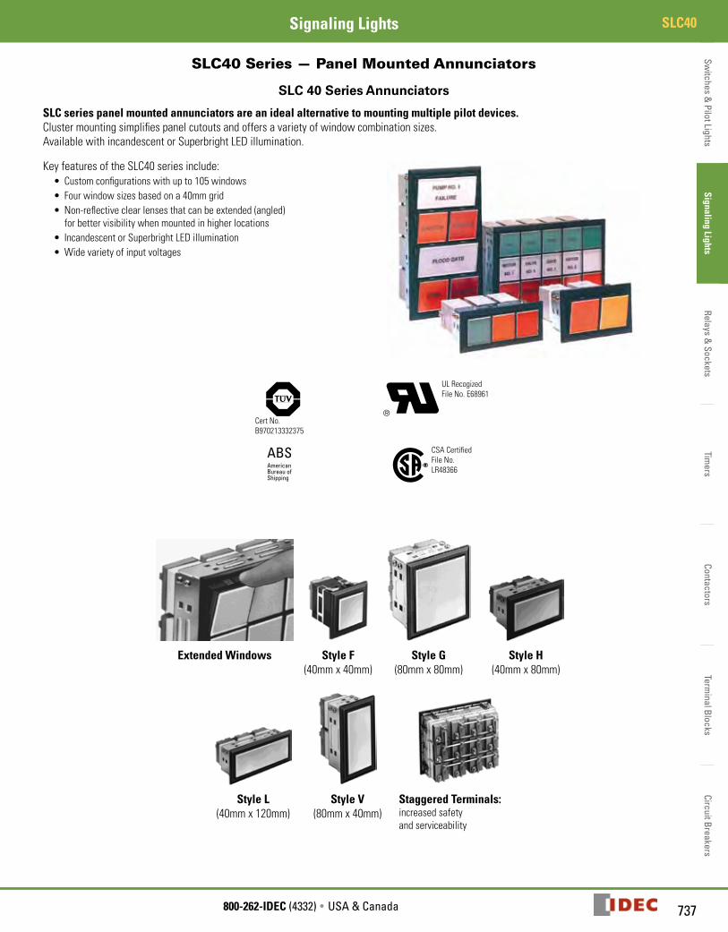
SLC series panel mounted annunciators are an ideal alternative to mounting multiple pilot devices. Cluster mounting simplifies panel cutouts and offers a variety of window combination sizes.Available with incandescent or Superbright LED illumination.
Key features of the SLC40 series include:• Custom configurations with up to 105 windows• Four window sizes based on a 40mm grid• Non-reflective clear lenses that can be extended (angled)
for better visibility when mounted in higher locations• Incandescent or Superbright LED illumination• Wide variety of input voltages
Cert No.B970213332375
UL RecogizedFile No. E68961
ABSAmericanBureau ofShipping
R
CSA CertifiedFile No. LR48366
Extended Windows Style F(40mm x 40mm)
Style G (80mm x 80mm)
Style H (40mm x 80mm)
Style L (40mm x 120mm)
Style V (80mm x 40mm)
Staggered Terminals: increased safety and serviceability

Switc
hes
& P
ilot L
ight
sSi
gnal
ing
Ligh
tsRe
lays
& S
ocke
tsTi
mer
sCo
ntac
tors
Term
inal
Blo
cks
Circ
uit B
reak
ers
SLC40 Signaling Lights
738 www.IDEC.com
Specifications
Light Source LED Incandescent
Nominal Voltages
Full Voltage 6, 12, 24V AC/DC 6, 12, 18, 24, 30V AC/DC
Transformer 120, 240V AC 120, 240V AC
DC-DC Conv. 110V DC —
ColorsFull voltage:Amber, Green, Red, Yellow, Blue (24V only), White, dual color Red/Green (24V only)
Amber, Green, Red, Yellow, Blue, White
Lamp Type Surface (Chip type) LED cluster E12/15 Screw terminal base (2W)
24V AC/DC 40mA 80mA
Current Consumption
12V AC/DC 80mA 160mA
6V AC/DC 160mA 330mA
Available Window Sizes“F" “H" “L" “V" “G"
40x40mm 40x80mm 40x120mm
80x40mm
80x80mm
Insulation Resistance 100MW minimum (with 500V DC megger), between live and dead parts
Degree of Protection IP20 (for indoor use only), Type 1
Dielectric Strength Full voltage: 2,000V AC direct Adaptor/transformer 2,500V AC (1 minute)
Operating Temperature – 20˚ to +40˚C; (45-85% relative humidity)
Material of Marking Plate and Color Screen Polycarbonate
Termination X1 and X2 terminals: M3.5 screw with a captive wire clamp washer(Check terminal: M3 screw on applicable models)
Maximum Size Full voltage: 7 rows, 15 columns (105 windows)Others: 50 windows maximum
Recommended Wire Size 22-14 AWG x2 (2mm2 x 2)
Approvals
Cert. No. B970213332375
UL RecognizedFile No. E68961
ABSAmericanBureau ofShipping
R
CSA CertifiedFile No. LR48366
Switches &
Pilot LightsSignaling Lights
Relays & Sockets
Timers
ContactorsTerm
inal BlocksCircuit Breakers
739800-262-IDEC (4332) • USA & Canada
SLC40Signaling Lights
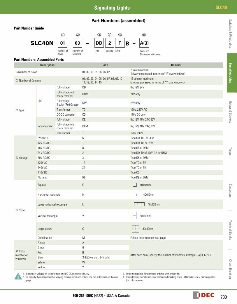
Part Numbers (assembled)
Part Number Guide
SLC40N 01 03 DD 2 F A(3)––Number ofRows
Number of Columns
Type Voltage Style Color andNumber of Windows
B
Part Numbers: Assembled PartsDescription Code Remark
Number of Rows 01, 02, 03, 04, 05, 06, 07 7 row maximum (always expressed in terms of “F" size windows)
Number of Columns01, 02, 03, 04, 05, 06, 07, 08, 09, 10 11, 12, 13, 14, 15
15 column maximum (always expressed in terms of “F" size windows)
Type
LED
Full voltage DD 6V, 12V, 24V
Full voltage with check terminal DHM 24V only
Full voltage 2 color (Red/Green) DW 24V only
Transformer TD 120V, 240V AC
DC-DC converter CD 110V DC only
Incandescent
Full voltage DE 6V, 12V, 18V, 24V, 30V
Full voltage with check terminal DEM 6V, 12V, 18V, 24V, 30V
Transformer TE 120V, 240V
Voltage
6V AC/DC 6 Type DD, DE, or DEM
12V AC/DC 1 Type DD, DE or DEM
18V AC/DC 8 Type DE or DEM
24V AC/DC 2 Type DD, DHM, DW, DE, or DEM
30V AC/DC 3 Type DE or DEM
120V AC 12 Type TD or TE
240V AC 24 Type TD or TE
110V DC 1 Type CD
No lamp 99 Type DE or DEM
n Style
Square F 40x40mm
Horizontal rectangle H 40x80mm
Large horizontal rectangle L 40x120mm
Vertical rectangle V
80x40mm
Large square G
80x80mm
Combination M Fill out order form on next page
o Color (number of windows)
Amber A
After each color, specify the number of windows Example... A(3), G(2), R(1)
Green G
Red R
Blue S (LED version: 24V only)
White W
Yellow Y
1. Secondary voltage on transformers and DC-DC converters is 24V.2. To specify the arrangement of varying window sizes and colors, use the order form on the next
page.
3. Drawing required for any units ordered with engraving.4. Incandescent models use color screen and marking plate, LED models use 2 marking plates
(no color screen).

Switc
hes
& P
ilot L
ight
sSi
gnal
ing
Ligh
tsRe
lays
& S
ocke
tsTi
mer
sCo
ntac
tors
Term
inal
Blo
cks
Circ
uit B
reak
ers
SLC40 Signaling Lights
740 www.IDEC.com
Order Form
Co
ntac
t __
____
____
____
____
____
____
____
___
Co
mpa
ny _
____
____
____
____
____
____
____
____
Ph
one
# _
____
____
____
____
____
____
____
____
Sh
ip to
___
____
____
____
____
____
____
____
__
_
____
____
____
____
____
____
____
____
City
/Sta
te/Z
ip _
____
____
____
____
____
____
____
____
Purc
hase
Ord
er N
o. _
____
____
____
___
D
ate
___
____
____
___
Sh
eet
of
THIS
SID
E U
P
1.
The
part
num
ber g
uide
is o
n th
e pr
evio
us p
age.
2.
Pane
l cut
out d
imen
sion
s ar
e on
pag
e 71
2.
COLU
MN
SRO
WS
Qua
ntity
___
____
__
Not
e: A
ll un
its o
rder
ed w
ith o
ne
orde
r for
m m
ust b
e id
entic
al
Rem
arks
:
THIS
SID
E U
P
B–
Blac
k
Fram
e
ANu
mbe
r of A
mbe
r
GNu
mbe
r of G
reen
RNu
mbe
r of R
ed
SNu
mbe
r of B
lue
WNu
mbe
r of W
hite
YNu
mbe
r of Y
ello
w
First
Win
dow
(u
pper
, lef
t-han
d co
rner
of p
anel
)
Basic
Uni
t Size
(style
F)
G =
Two
x Tw
o
F =
One
Win
dow
H =
Two
Win
dow
s Wid
eL
= Th
ree
Win
dow
s Wid
eV
= Tw
o W
indo
ws H
igh
M =
Mul
tiple
Com
bina
tion
Not
e: C
onve
rt al
l win
dow
style
s to
the
style
F (b
asic
unit
size)
.
Num
ber o
f Ro
ws
Num
ber o
f Co
lum
nsTy
pe
Code
Oper
atin
g Vo
ltage
Style
Co
de
SLC
40N
—
—
Fill
in P
art
Nu
mb
er B
elow
:
For e
ngra
ving
info
rmat
ion,
see
pa
ge 7
15.
For i
nfor
mat
ion
on h
ow to
com
plet
e th
e or
der f
orm
or t
o vi
ew e
xam
ples
, see
th
e fo
llow
ing
page
.
Switches &
Pilot LightsSignaling Lights
Relays & Sockets
Timers
ContactorsTerm
inal BlocksCircuit Breakers
741800-262-IDEC (4332) • USA & Canada
SLC40Signaling Lights
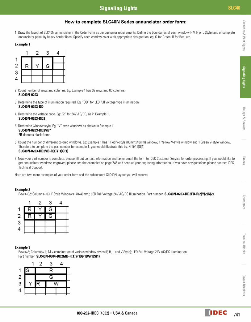
How to complete SLC40N Series annunciator order form:
1. Draw the layout of SLC40N annunciator in the Order Form as per customer requirements. Define the boundaries of each window (F, V, H or L Style) and of complete annunciator panel by heavy border lines. Specify each window color with appropriate designation: eg: G for Green, R for Red, etc.
Example 1
2. Count number of rows and columns. Eg: Example 1 has 02 rows and 03 columns. SLC40N-0203
3. Determine the type of illumination required. Eg: “DD” for LED full voltage type illumination. SLC40N-0203-DD
4. Determine the voltage code. Eg: “2” for 24V AC/DC, as in Example 1. SLC40N-0203-DD2
5. Determine window style. Eg: “V” style windows as shown in Example 1. SLC40N-0203-DD2VB* *B denotes black frame.
6. Count the number of different colored windows. Eg: Example 1 has 1 Red V-style (80mmx40mm) window, 1 Yellow V-style window and 1 Green V-style window. Therefore to complete the part number for example 1, you would illustrate this by: R(1)Y(1)G(1) SLC40N-0203-DD2VB-R(1)Y(1)G(1)
7. Now your part number is complete, please fill out contact information and fax or email the form to IDEC Customer Service for order processing. If you would like to get annunciator windows engraved, please see the examples on page 745 and send us your engraving information. If you have any questions please contact IDEC Technical Support.
Here are two more examples of your order form and the subsequent SLC40N layout you will receive.
Example 2 Rows=02; Columns= 03; F Style Windows (40x40mm); LED Full Voltage 24V AC/DC Illumination. Part number SLC40N-0203-DD2FB-R(2)Y(2)G(2).
Example 3 Rows=3; Columns= 4; M = combination of various window styles (F, H, L and V Style); LED Full Voltage 24V AC/DC Illumination. Part number SLC40N-0304-DD2MB-R(1)Y(1)G(1)W(1)S(1).

Switc
hes
& P
ilot L
ight
sSi
gnal
ing
Ligh
tsRe
lays
& S
ocke
tsTi
mer
sCo
ntac
tors
Term
inal
Blo
cks
Circ
uit B
reak
ers
SLC40 Signaling Lights
742 www.IDEC.com
Dimensions
Panel Cut-Out Dimensions
No.
of R
ows
No. of Columns 1 2 3 4 5 6 7 8 9 10 11 12 13 14 15
Overall Panel Width Dimension g
2.20
5"(5
6mm
)
3.78
0"
(96m
m)
5.35
4"
(136
mm
)
6.92
9"
(176
mm
)
8.50
4"
(216
mm
)
10.0
79"
(256
mm
)
11.6
54"
(296
mm
)
13.2
28"
(336
mm
)
14.8
04"
(376
mm
)
16.3
78"
(416
mm
)
17.9
53"
(456
mm
)
19.5
28"
(496
mm
)
21.1
02"
(536
mm
)
22.6
77"
(576
mm
)
24.2
52"
(616
mm
)
Overall Height i
Cut-out Ht i
Cut-out Wdg 1.
772"
(4
5mm
)
3.34
6"
(85m
m)
4.92
1"
(125
mm
)
6.49
6"
(165
mm
)
8.07
1"
(205
mm
)
9.64
6"
(245
mm
)
11.2
20"
(285
mm
)
12.7
95"
(325
mm
)
14.3
70"
(365
mm
)
15.9
45"
(405
mm
)
17.5
20"
(445
mm
)
19.0
94"
(485
mm
)
20.6
69"
(525
mm
)
22.2
44"
(565
mm
)
23.8
19"
(605
mm
)
1 2.205" (56mm)
1.772" (45mm) 1 2 3 4 5 6 7 8 9 10 11 12 13 14 15
2 3.780" (96mm)
3.346" (85mm) 2 4 6 8 10 12 14 16 18 20 22 24 26 28 30
3 5.354" (136mm)
4.921" (125mm) 3 6 9 12 15 18 21 24 27 30 33 36 39 42 45
4 6.929" (176mm)
6.496" (165mm) 4 8 12 16 20 24 28 32 36 40 44 48 52 56 60
5 8.504" (216mm)
8.071" (205mm) 5 10 15 20 25 30 35 40 45 50 55 60 65 70 75
6 10.079" (256mm)
9.646" (245mm) 6 12 18 24 30 36 42 48 54 60 66 72 78 84 90
7 11.654" (296mm)
11.220" (285mm) 7 14 21 28 35 42 49 56 63 70 77 84 91 98 105
Total Number of Windows (equivalent to style F—basic unit size)
1. The number of rows and columns refers to styles equivalent to style F (basic unit size). For styles H, L, V, and G, convert into style F (basic unit size) equivalents. Style H: 1 window high (1 row) x 2 windows wide (2 columns) Style V: 2 windows high (2 rows) x 1 window wide (1 column) Style L: 1 window high (1 row) x 3 windows wide (3 columns) Style G: 2 windows high (2 rows) x 2 windows wide (2 columns) Example: 18 windows = 3 windows high (3 rows) x 6 windows wide (6 columns) Overall dimension (H x W): 5.354" x 10.079" (136 x 256mm) Panel cut-out (H x W): 4.921" x 9.646" (125 x 245mm) Tolerance: +0.039" (1mm), –0
2. See page 739 for part numbering information. Window Dimensions
Window Style Style F Style H Style L Style V
Appearance
Window Size
Illumination Face (H x W) 1.575" x 1.575" (40 x 40mm) 1.575" x 3.150" (40 x 80mm) 1.575" x 4.724" (40 x 120mm) 3.150" x 1.575" (80 x 40mm)
Lens (H x W) 1.457" x 1.457" (37 x 37mm) 1.457" x 3.031" (37 x 77mm) 1.457" x 4.606" (37 x 117mm) 3.031" x 1.457" (77 x 37mm)
Marking Plate(H x W x t)
1.409" x 1.409" x 0.04" (35.8 x 35.8 x 1.0mm)
1.409" x 2.984" x 0.04" (35.8 x 75.8 x 1.0mm)
1.409" x 4.559" x 0.04" (35.8 x 115.8 x 1.0mm)
2.984" x 1.409" x 0.04" (75.8 x 35.8 x 1.0mm)
Color Screen(H x W x t)
1.409" x 1.409" x 0.04" (35.8 x 35.8 x 1.0mm)
1.409" x 2.984" x 0.04" (35.8 x 75.8 x 1.0mm)
1.409" x 4.559" x 0.04" (35.8 x 115.8 x 1.0mm)
2.984" x 1.409" x 0.04" (75.8 x 35.8 x 1.0mm)
Engraving Area 1.339" x 1.339" (34 x 34mm)
1.339" x 2.913" (34 x 55mm)
1.339" x 4.488" (34 x 85mm)
2.913" x 1.339" (55 x 34mm)
743800-262-IDEC (4332) • USA & Canada
SLC40Signaling LightsSw
itches & Pilot Lights
Signaling LightsRelays &
SocketsTim
ersContactors
Terminal Blocks
Circuit Breakers
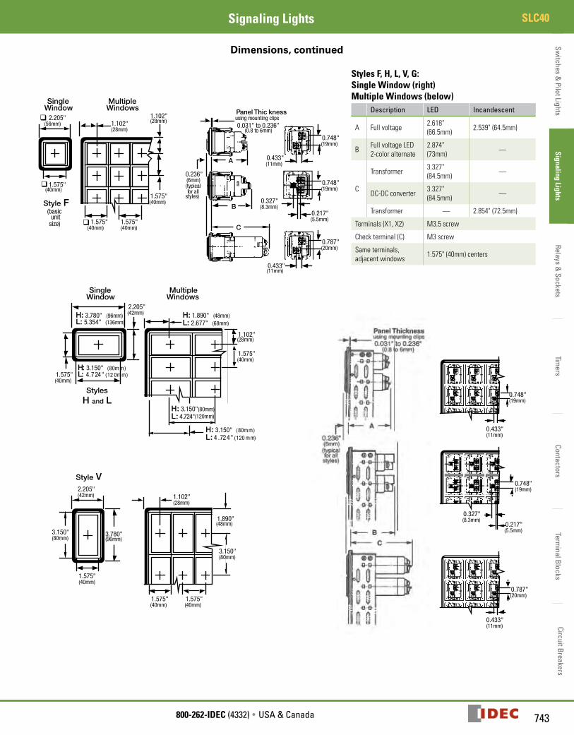
Dimensions, continued
Styles F, H, L, V, G:Single Window (right)Multiple Windows (below)
Description LED Incandescent
A Full voltage 2.618" (66.5mm) 2.539" (64.5mm)
B Full voltage LED 2-color alternate
2.874" (73mm) —
C
Transformer 3.327"(84.5mm) —
DC-DC converter 3.327"(84.5mm) —
Transformer — 2.854" (72.5mm)
Terminals (X1, X2) M3.5 screw
Check terminal (C) M3 screw
Same terminals, adjacent windows 1.575" (40mm) centers

Switc
hes
& P
ilot L
ight
sSi
gnal
ing
Ligh
tsRe
lays
& S
ocke
tsTi
mer
sCo
ntac
tors
Term
inal
Blo
cks
Circ
uit B
reak
ers
SLC40 Signaling Lights
744 www.IDEC.com
Dimensions, continued
Instructions
Estimating Weights
A x Rows
+Columns
+ B x Rows
xColumns
+ C x Rows
xColumns
= Total Weight of Display Panel
1. Make sure that the panel thickness is sufficient to support the total weight of the display panel(s).
Full Voltage Transformer (incandescent) AC Adapter (LED) DC-DC Converter (LED only)
A Frame Weight
B Housing Weight
C Lamp/LED Weight (includes lamp/LED)
0.93oz (30g) 0.93oz (30g) 0.93oz (30g) 2.98oz (96g) 1.92oz (62g)
2. Weights are approximate.
Example: SLC40N-0304-DD2FB Total weight = A (rows + columns) + B (rows x columns) + C (rows x columns) Total weight = 0.93 (3+4) + 0.93 (3x4) + 0.93 (3x4) = 28.83 oz
Switches &
Pilot LightsSignaling Lights
Relays & Sockets
Timers
ContactorsTerm
inal BlocksCircuit Breakers
745800-262-IDEC (4332) • USA & Canada
SLC40Signaling Lights
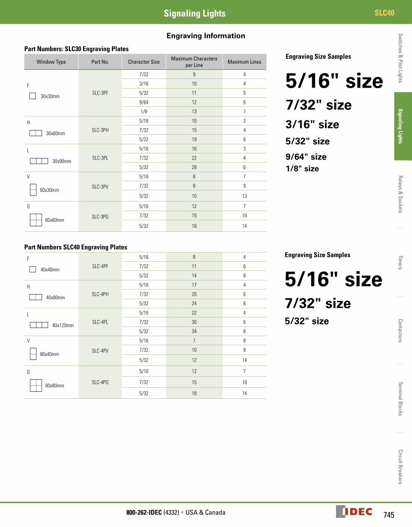
Engraving Information
Part Numbers: SLC30 Engraving Plates
Window Type Part No. Character Size Maximum Characters per Line Maximum Lines
Engraving Size Samples
5/16" size7/32" size3/16" size5/32" size
9/64" size1/8" size
F
30x30mmSLC-3PF
7/32 9 4
3/16 10 4
5/32 11 5
9/64 12 6
1/8 13 7
H
30x60mmSLC-3PH
5/16 10 3
7/32 15 4
5/32 19 6
L
30x90mmSLC-3PL
5/16 16 3
7/32 22 4
5/32 28 6
V
60x30mm
SLC-3PV
5/16 6 7
7/32 8 9
5/32 10 13
G
60x60mm
SLC-3PG
5/16 12 7
7/32 15 10
5/32 18 14
Part Numbers SLC40 Engraving Plates
F
40x40mmSLC-4PF
5/16 8 4 Engraving Size Samples
5/16" size7/32" size5/32" size
7/32 11 6
5/32 14 8
H
40x80mmSLC-4PH
5/16 17 4
7/32 20 6
5/32 24 8
L
40x120mmSLC-4PL
5/16 22 4
7/32 30 6
5/32 34 8
V
80x40mm
SLC-4PV
5/16 7 8
7/32 10 9
5/32 12 14
G
80x80mm
SLC-4PG
5/16 12 7
7/32 15 10
5/32 18 14
Switc
hes
& P
ilot L
ight
sSi
gnal
ing
Ligh
tsRe
lays
& S
ocke
tsTi
mer
sCo
ntac
tors
Term
inal
Blo
cks
Circ
uit B
reak
ers
SLC40 Signaling Lights
746 www.IDEC.com
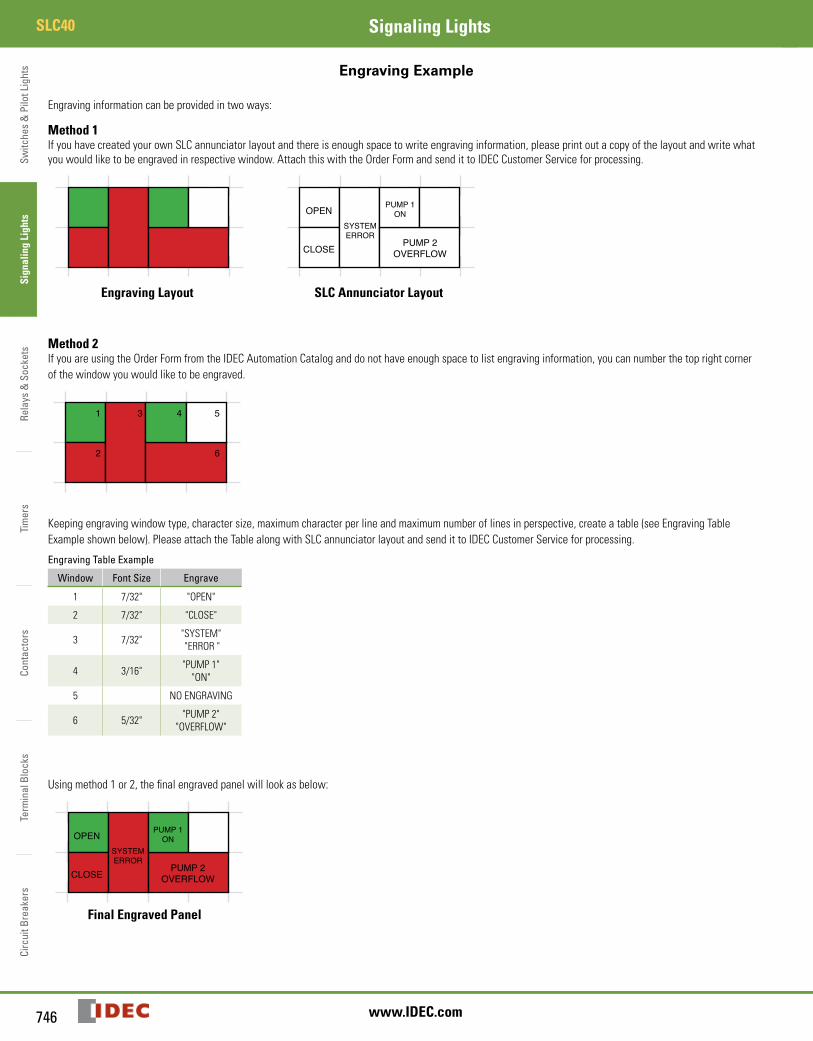
Engraving Example
Engraving information can be provided in two ways:
Method 1If you have created your own SLC annunciator layout and there is enough space to write engraving information, please print out a copy of the layout and write what you would like to be engraved in respective window. Attach this with the Order Form and send it to IDEC Customer Service for processing.
OPEN
CLOSE
SYSTEMERROR
PUMP 1ON
PUMP 2OVERFLOW
OPEN
CLOSE
SYSTEMERROR
PUMP 1ON
PUMP 2OVERFLOW
1
2
3 4 5
6
OPEN
CLOSE
SYSTEMERROR
PUMP 1ON
PUMP 2OVERFLOW
OPEN
CLOSE
SYSTEMERROR
PUMP 1ON
PUMP 2OVERFLOW
1
2
3 4 5
6
Engraving Layout SLC Annunciator Layout
Method 2If you are using the Order Form from the IDEC Automation Catalog and do not have enough space to list engraving information, you can number the top right corner of the window you would like to be engraved.
OPEN
CLOSE
SYSTEMERROR
PUMP 1ON
PUMP 2OVERFLOW
OPEN
CLOSE
SYSTEMERROR
PUMP 1ON
PUMP 2OVERFLOW
1
2
3 4 5
6
Keeping engraving window type, character size, maximum character per line and maximum number of lines in perspective, create a table (see Engraving Table Example shown below). Please attach the Table along with SLC annunciator layout and send it to IDEC Customer Service for processing.
Engraving Table Example
Window Font Size Engrave
1 7/32" "OPEN"
2 7/32" "CLOSE"
3 7/32" "SYSTEM" "ERROR "
4 3/16" "PUMP 1" "ON"
5 NO ENGRAVING
6 5/32" "PUMP 2" "OVERFLOW"
Using method 1 or 2, the final engraved panel will look as below:
OPEN
CLOSE
SYSTEMERROR
PUMP 1ON
PUMP 2OVERFLOW
OPEN
CLOSE
SYSTEMERROR
PUMP 1ON
PUMP 2OVERFLOW
1
2
3 4 5
6
Final Engraved Panel
Switches &
Pilot LightsSignaling Lights
Relays & Sockets
Timers
ContactorsTerm
inal BlocksCircuit Breakers
747800-262-IDEC (4332) • USA & Canada
SLC40Signaling Lights
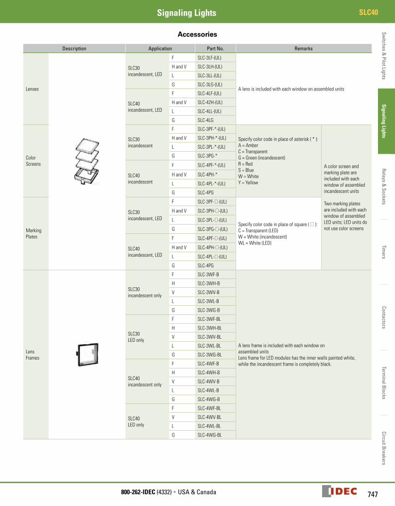
Accessories
Description Application Part No. Remarks
Lenses
SLC30 incandescent, LED
F SLC-3LF-(UL)
A lens is included with each window on assembled units
H and V SLC-3LH-(UL)
L SLC-3LL-(UL)
G SLC-3LG-(UL)
SLC40 incandescent, LED
F SLC-4LF-(UL)
H and V SLC-42H-(UL)
L SLC-4LL-(UL)
G SLC-4LG
Color Screens
SLC30incandescent
F SLC-3PF-*-(UL)
Specify color code in place of asterisk ( * ):A = AmberC = TransparentG = Green (incandescent)R = RedS = BlueW = WhiteY = Yellow
A color screen and marking plate are included with each window of assembled incandescent units
Two marking plates are included with each window of assembled LED units; LED units do not use color screens
H and V SLC-3PH-*-(UL)
L SLC-3PL-*-(UL)
G SLC-3PG-*
SLC40incandescent
F SLC-4PF-*-(UL)
H and V SLC-4PH-*
L SLC-4PL-*-(UL)
G SLC-4PG
Marking Plates
SLC30 incandescent, LED
F SLC-3PF-0-(UL)
Specify color code in place of square ( 0 ):C = Transparent (LED)W = White (incandescent)WL = White (LED)
H and V SLC-3PH-0-(UL)
L SLC-3PL-0-(UL)
G SLC-3PG-0-(UL)
SLC40incandescent, LED
F SLC-4PF-0-(UL)
H and V SLC-4PH-0-(UL)
L SLC-4PL-0-(UL)
G SLC-4PG
Lens Frames
SLC30incandescent only
F SLC-3WF-B
A lens frame is included with each window on assembled unitsLens frame for LED modules has the inner walls painted white, while the incandescent frame is completely black.
H SLC-3WH-B
V SLC-3WV-B
L SLC-3WL-B
G SLC-3WG-B
SLC30LED only
F SLC-3WF-BL
H SLC-3WH-BL
V SLC-3WV-BL
L SLC-3WL-BL
G SLC-3WG-BL
SLC40incandescent only
F SLC-4WF-B
H SLC-4WH-B
V SLC-4WV-B
L SLC-4WL-B
G SLC-4WG-B
SLC40LED only
F SLC-4WF-BL
V SLC-4WV-BL
L SLC-4WL-BL
G SLC-4WG-BL
Switc
hes
& P
ilot L
ight
sSi
gnal
ing
Ligh
tsRe
lays
& S
ocke
tsTi
mer
sCo
ntac
tors
Term
inal
Blo
cks
Circ
uit B
reak
ers
SLC40 Signaling Lights
748 www.IDEC.com
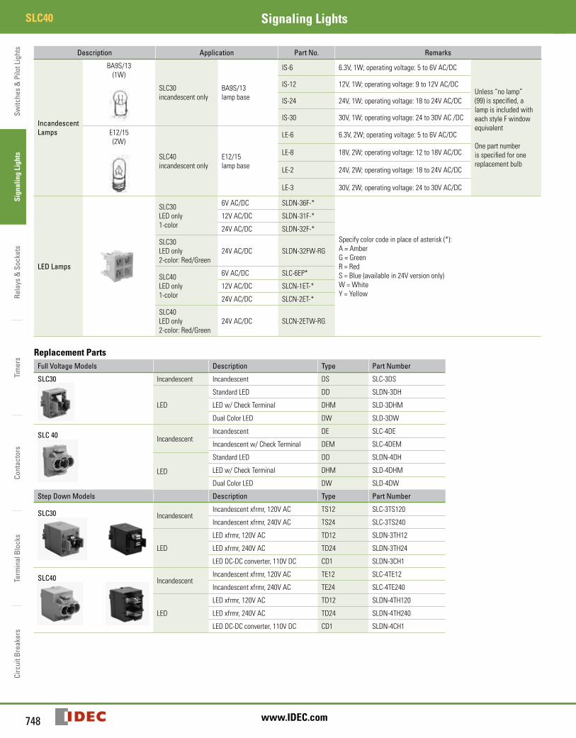
Description Application Part No. Remarks
IncandescentLamps
BA9S/13(1W)
SLC30incandescent only
BA9S/13lamp base
IS-6 6.3V, 1W; operating voltage: 5 to 6V AC/DC
Unless “no lamp” (99) is specified, a lamp is included with each style F window equivalent
One part number is specified for one replacement bulb
IS-12 12V, 1W; operating voltage: 9 to 12V AC/DC
IS-24 24V, 1W; operating voltage: 18 to 24V AC/DC
IS-30 30V, 1W; operating voltage: 24 to 30V AC /DC
E12/15(2W)
SLC40incandescent only
E12/15lamp base
LE-6 6.3V, 2W; operating voltage: 5 to 6V AC/DC
LE-8 18V, 2W; operating voltage: 12 to 18V AC/DC
LE-2 24V, 2W; operating voltage: 18 to 24V AC/DC
LE-3 30V, 2W; operating voltage: 24 to 30V AC/DC
LED Lamps
SLC30LED only1-color
6V AC/DC SLDN-36F-*
Specify color code in place of asterisk (*):A = AmberG = Green R = RedS = Blue (available in 24V version only)W = WhiteY = Yellow
12V AC/DC SLDN-31F-*
24V AC/DC SLDN-32F-*
SLC30LED only2-color: Red/Green
24V AC/DC SLDN-32FW-RG
SLC40LED only1-color
6V AC/DC SLC-6EP*
12V AC/DC SLCN-1ET-*
24V AC/DC SLCN-2ET-*
SLC40LED only2-color: Red/Green
24V AC/DC SLCN-2ETW-RG
Replacement PartsFull Voltage Models Description Type Part Number
SLC30 Incandescent Incandescent DS SLC-3DS
LED
Standard LED DD SLDN-3DH
LED w/ Check Terminal DHM SLD-3DHM
Dual Color LED DW SLD-3DW
SLC 40 IncandescentIncandescent DE SLC-4DE
Incandescent w/ Check Terminal DEM SLC-4DEM
Standard LED DD SLDN-4DH
LED LED w/ Check Terminal DHM SLD-4DHM
Dual Color LED DW SLD-4DW
Step Down Models Description Type Part Number
SLC30 IncandescentIncandescent xfrmr, 120V AC TS12 SLC-3TS120
Incandescent xfrmr, 240V AC TS24 SLC-3TS240
LED
LED xfrmr, 120V AC TD12 SLDN-3TH12
LED xfrmr, 240V AC TD24 SLDN-3TH24
LED DC-DC converter, 110V DC CD1 SLDN-3CH1
SLC40 IncandescentIncandescent xfrmr, 120V AC TE12 SLC-4TE12
Incandescent xfrmr, 240V AC TE24 SLC-4TE240
LED
LED xfrmr, 120V AC TD12 SLDN-4TH120
LED xfrmr, 240V AC TD24 SLDN-4TH240
LED DC-DC converter, 110V DC CD1 SLDN-4CH1
Switches &
Pilot LightsSignaling Lights
Relays & Sockets
Timers
ContactorsTerm
inal BlocksCircuit Breakers
749800-262-IDEC (4332) • USA & Canada
SLC40Signaling Lights
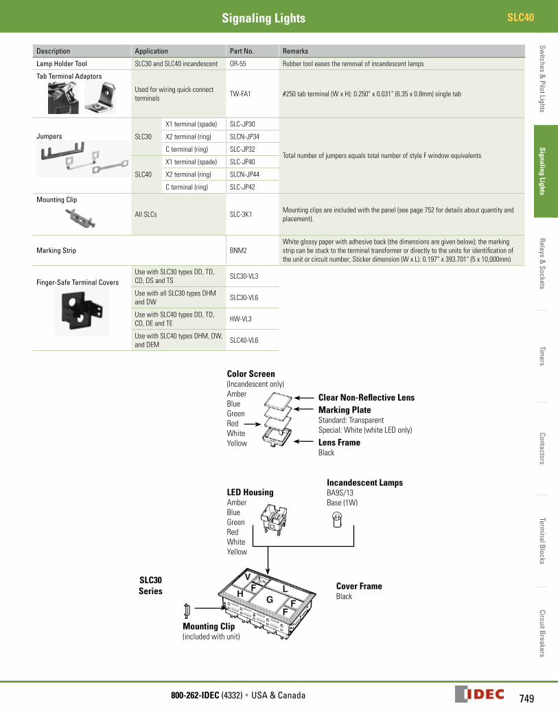
Description Application Part No. Remarks
Lamp Holder Tool SLC30 and SLC40 incandescent OR-55 Rubber tool eases the removal of incandescent lamps
Tab Terminal Adaptors
Used for wiring quick-connect terminals TW-FA1 #250 tab terminal (W x H): 0.250" x 0.031" (6.35 x 0.8mm) single tab
Jumpers SLC30
X1 terminal (spade) SLC-JP30
Total number of jumpers equals total number of style F window equivalents
X2 terminal (ring) SLCN-JP34
C terminal (ring) SLC-JP32
SLC40
X1 terminal (spade) SLC-JP40
X2 terminal (ring) SLCN-JP44
C terminal (ring) SLC-JP42
Mounting Clip
All SLCs SLC-3K1 Mounting clips are included with the panel (see page 752 for details about quantity and placement).
Marking Strip BNM2White glossy paper with adhesive back (the dimensions are given below); the marking strip can be stuck to the terminal transformer or directly to the units for identification of the unit or circuit number; Sticker dimension (W x L): 0.197" x 393.701" (5 x 10,000mm)
Finger-Safe Terminal CoversUse with SLC30 types DD, TD, CD, DS and TS SLC30-VL3
Use with all SLC30 types DHM and DW SLC30-VL6
Use with SLC40 types DD, TD, CD, DE and TE HW-VL3
Use with SLC40 types DHM, DW, and DEM SLC40-VL6
Color Screen (Incandescent only) Amber Blue Green Red White Yellow
Cover Frame Black
Clear Non-Reflective LensMarking Plate Standard: Transparent Special: White (white LED only)
Incandescent Lamps BA9S/13Base (1W)
Mounting Clip (included with unit)
SLC30 Series
LED Housing Amber Blue Green Red White Yellow
Lens Frame Black
Switc
hes
& P
ilot L
ight
sSi
gnal
ing
Ligh
tsRe
lays
& S
ocke
tsTi
mer
sCo
ntac
tors
Term
inal
Blo
cks
Circ
uit B
reak
ers
SLC40 Signaling Lights
750 www.IDEC.com
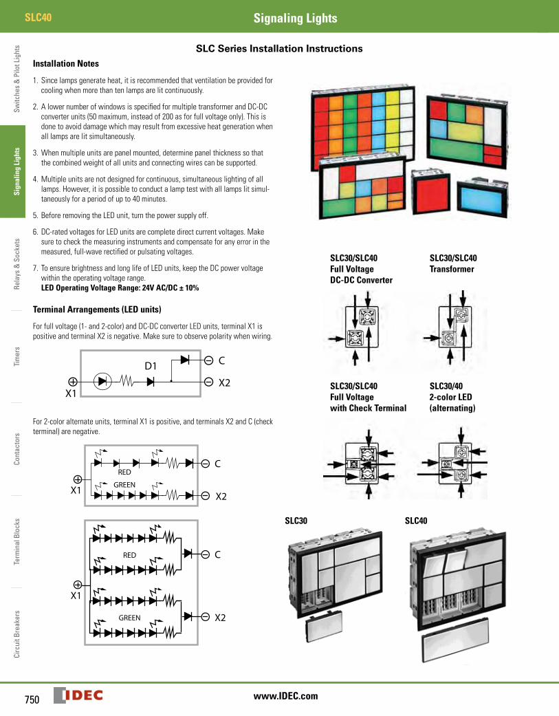
SLC Series Installation InstructionsInstallation Notes
1. Since lamps generate heat, it is recommended that ventilation be provided for cooling when more than ten lamps are lit continuously.
2. A lower number of windows is specified for multiple transformer and DC-DC converter units (50 maximum, instead of 200 as for full voltage only). This is done to avoid damage which may result from excessive heat generation when all lamps are lit simultaneously.
3. When multiple units are panel mounted, determine panel thickness so that the combined weight of all units and connecting wires can be supported.
4. Multiple units are not designed for continuous, simultaneous lighting of all lamps. However, it is possible to conduct a lamp test with all lamps lit simul-taneously for a period of up to 40 minutes.
5. Before removing the LED unit, turn the power supply off.
6. DC-rated voltages for LED units are complete direct current voltages. Make sure to check the measuring instruments and compensate for any error in the measured, full-wave rectified or pulsating voltages.
7. To ensure brightness and long life of LED units, keep the DC power voltage within the operating voltage range. LED Operating Voltage Range: 24V AC/DC ± 10%
Terminal Arrangements (LED units)
For full voltage (1- and 2-color) and DC-DC converter LED units, terminal X1 is positive and terminal X2 is negative. Make sure to observe polarity when wiring.
D1
X1X2
C
X1
RED
GREEN
RED
GREEN
C
X1
X2
C
X2
For 2-color alternate units, terminal X1 is positive, and terminals X2 and C (check terminal) are negative.
D1
X1X2
C
X1
RED
GREEN
RED
GREEN
C
X1
X2
C
X2
SLC30/SLC40Full VoltageDC-DC Converter
SLC30/SLC40Transformer
SLC30/SLC40Full Voltagewith Check Terminal
SLC30/402-color LED(alternating)
SLC30 SLC40

Switches &
Pilot LightsSignaling Lights
Relays & Sockets
Timers
ContactorsTerm
inal BlocksCircuit Breakers
751800-262-IDEC (4332) • USA & Canada
SLC40Signaling Lights
Installation Instructions, continuedRemoving Windows
SLC30: To remove a window, insert the tip of a small screwdriver into the slot under the lens frame and gently press down on the screwdriver.
SLC40: To remove an extended window, pull on the top as if to extend the unit; then continue pulling until the unit comes out of the housing. All units are shipped with windows retracted. When transporting units, make sure windows are pushed in fully. After windows are installed, they can be extended as shown in Figure 1.
Removing Lens, Color Screen, and Marking Plate
The lens has two retaining projections on the right and two on the left. To remove the lens, color screen, and marking plate from the lens frame, push open the lens frame with both hands as shown in Figure 2.
The lens can also be removed by inserting a screwdriver into one of the sides with recesses. Since the lens has an orientation, be sure to insert the screw-driver in the direction shown in Figures 3 and 4.
Figure 3: SLC30 Figure 4: SLC40
Installing Lens, Color Screen, and Marking Plate
First, install the marking plate and color screen into the lens frame. To install the lens, insert its retaining projections into the recesses inside the lens frame, and press the lens into the lens frame as shown in Figure 5.
Lens Marking Plate Color Screen Lens Frame
Figure 5: SLC30 and SLC40
Replacing the LED Unit
To remove: Insert the tip of a screwdriver into one of the two slots inside the LED unit. Pull the LED unit straight out without pressing on the LED terminals, as shown in Figure 6.
To install: Make sure that the junction inside the LED unit is aligned in the same direction as the junction of the LED housing. Push the LED unit into the LED housing as shown in Figure 7.
Figure 6: Remove LED Figure 7: Install LED
Installing Units into a Panel
Single units: With leaf springs installed, push the SLC housing from the front of the panel. Secure the SLC housing with two mounting clips. Tighten the mount-ing clip screws to a torque of 4 to 5 kgf-cm as shown in Figure 8.
Figure 8: SLC40
Multiple combination units: Insert the units into the panel cut-out from the front. Install the attached mounting clips into the openings on the frame, and tighten the screws as shown in Figure 9. After tightening, use Loctite to prevent loosening. The number of mounting clips included with each multiple unit varies with the number of windows as shown in the table below.
Figure 9: Multiple Combination
Switc
hes
& P
ilot L
ight
sSi
gnal
ing
Ligh
tsRe
lays
& S
ocke
tsTi
mer
sCo
ntac
tors
Term
inal
Blo
cks
Circ
uit B
reak
ers
SLC40 Signaling Lights
752 www.IDEC.com
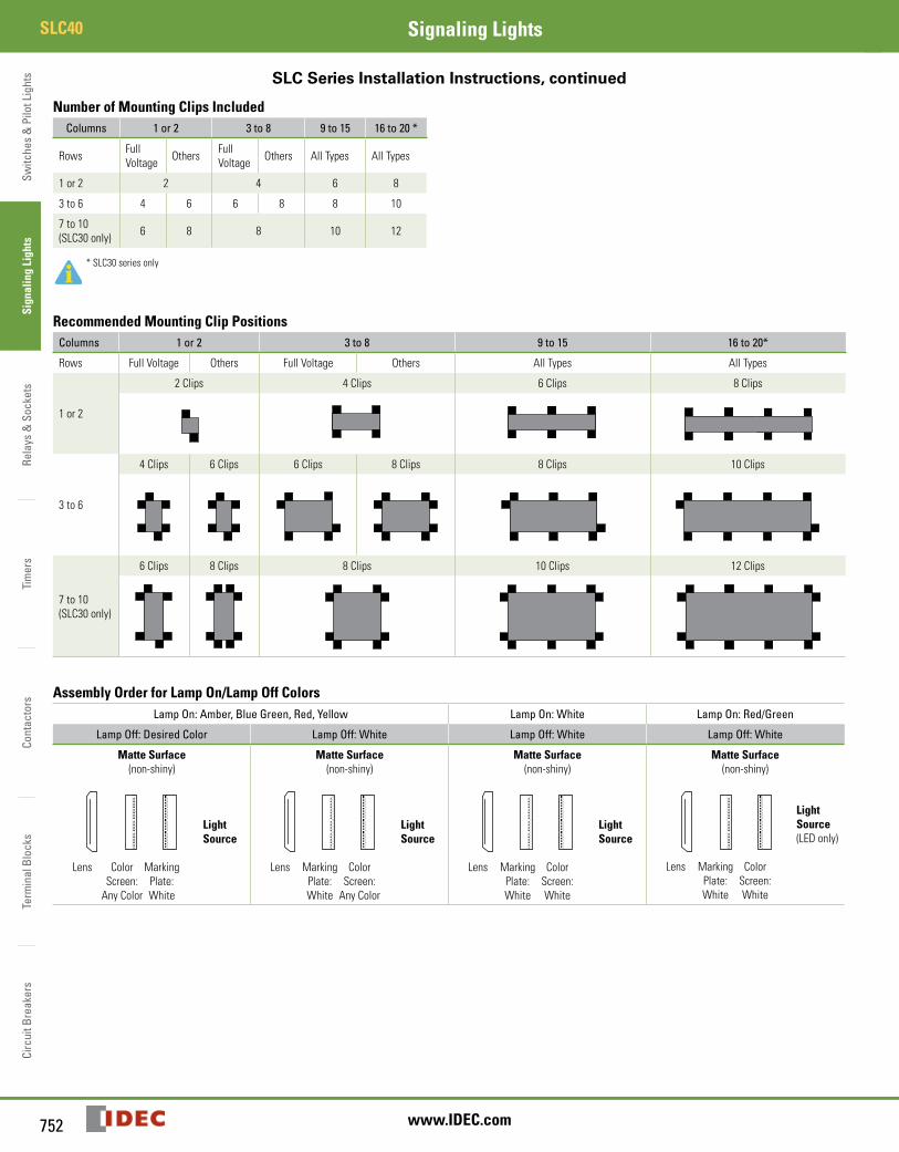
SLC Series Installation Instructions, continued
Number of Mounting Clips IncludedColumns 1 or 2 3 to 8 9 to 15 16 to 20 *
Rows Full Voltage Others Full
Voltage Others All Types All Types
1 or 2 2 4 6 8
3 to 6 4 6 6 8 8 10
7 to 10(SLC30 only) 6 8 8 10 12
* SLC30 series only
Recommended Mounting Clip PositionsColumns 1 or 2 3 to 8 9 to 15 16 to 20*
Rows Full Voltage Others Full Voltage Others All Types All Types
1 or 2
2 Clips 4 Clips 6 Clips 8 Clips
3 to 6
4 Clips 6 Clips 6 Clips 8 Clips 8 Clips 10 Clips
7 to 10(SLC30 only)
6 Clips 8 Clips 8 Clips 10 Clips 12 Clips
Assembly Order for Lamp On/Lamp Off ColorsLamp On: Amber, Blue Green, Red, Yellow Lamp On: White Lamp On: Red/Green
Lamp Off: Desired Color Lamp Off: White Lamp Off: White Lamp Off: White
Matte Surface(non-shiny)
Light Source
Lens Color Marking Screen: Plate: Any Color White
Matte Surface(non-shiny)
Light Source
Lens Marking Color Plate: Screen: White Any Color
Matte Surface(non-shiny)
Light Source
Lens Marking Color Plate: Screen: White White
Matte Surface(non-shiny)
Light Source (LED only)
Lens Marking Color Plate: Screen: White White