Embed Size (px)
Citation preview

Prof. Dr.-Ing. I. Willms Transmission and Modulation S. 1
FachgebietNachrichtentechnische Systeme
N T S
Signal Transmission and Modulation
Prof. Dr.-Ing. Ingolf Willms
Partly based on the script of Prof. Thomas Kaiser

Prof. Dr.-Ing. I. Willms Transmission and Modulation S. 2
FachgebietNachrichtentechnische Systeme
N T S
Chapter 4
Digital TM
4.1 Basics of detection theory

Prof. Dr.-Ing. I. Willms Transmission and Modulation S. 3
FachgebietNachrichtentechnische Systeme
N T S
4.1 Basics of Detection TheoryDigital TM:
- required is to transmit data streams with lowest bit error rate (BER)
- thus optimal distinguishment of binäry data on the base of a sequence of predefined functions are needed
- combining M binary data leads to distinguishing 2M symbols zu unterscheiden

Prof. Dr.-Ing. I. Willms Transmission and Modulation S. 4
FachgebietNachrichtentechnische Systeme
N T S
TM method applied now: Signal x(t) is transmitted in case (H1) of „logical 1“, no signal in case (H0) of „logical 0“.
Signal x(t) has a duration of T and an energy of Ex.
Additive Gausssian noise n(t) is assumed Für die beiden Fälle H0 und H1 gilt damit:
4.1 Basics of Detection Theory
2
0
( )T
xE x t dt
0 1: ( ) ( ) : ( ) ( ) ( )H y t n t H y t x t n t

Prof. Dr.-Ing. I. Willms Transmission and Modulation S. 5
FachgebietNachrichtentechnische Systeme
N T S
The receiver has to decide on the base of y(t) for the case of H0 or H1 .
Instead of y(t) now coefficients of a set of orthonormal functions fn(t)describing it are evaluated for which hold:
4.1 Basics of Detection Theory
0 0
( ) ( ) mit ( ) ( ) und 1n
T
n n n n fn t
y t Y f t Y y t f t dt E n
Due to linear relations of coefficients and the functions hold:
n n nY X N 0 0
0 0
( ) ( ) mit ( ) ( )
( ) ( ) mit ( ) ( )
T
n n n nn t
T
n n n nn t
x t X f t X x t f t dt
n t N f t N n t f t dt

Prof. Dr.-Ing. I. Willms Transmission and Modulation S. 6
FachgebietNachrichtentechnische Systeme
N T S
The best detection situation can be obtained by choosing a proper set of functions fn(t) with:
4.1 Basics of Detection Theory
0 ( ) ( ) / xf t x t E
This gives:
0 0 00
0 00 0
0 0
( ) ( ) ( ) ( )
( )due to X ( ) ( ) ( )
which leads to . Important is: 0
n n xn
T Tx
t t x x
x
x t X f t X f t E f t
Ex tx t f t dt x t dtE E
X E X

Prof. Dr.-Ing. I. Willms Transmission and Modulation S. 7
FachgebietNachrichtentechnische Systeme
N T S
For making the decision now the follwing data have to becompared:
4.1 Basics of Detection Theory
0 0 0 1 1 2 2
1 0 0 0 1 1 1 1 2 2
: ...: ...
H Y N Y N Y NH Y X N Y X N N Y N
0 00 0
1 0 0
Thus only on the basis of
1( ) ( ) ( ) ( )
the decision can be made.In case of , is always larger than in case of !
T T
t tx
Y y t f t dt y t x t dtE
H Y H

Prof. Dr.-Ing. I. Willms Transmission and Modulation S. 8
FachgebietNachrichtentechnische Systeme
N T S
4.1 Basics of Detection Theory
• Example with separation into sine functions and matching x(t)• The Xn here represent the Fourier coefficients bn
0
0 0
2 00
0
0 0 00
0 00
( ) ( / - 0.5)sin( )
sin ( )2
2( ) ( ) / ( / - 0.5)sin( )
2( ) ( / - 0.5)sin( )
T
x
x
n
x t rect t T t
TE t dt
f t x t E rect t T tT
f t rect t T n tT
0
0 0
( ) ( ) mit ( ) ( )T
n n n nn t
x t X f t X x t f t dt
Prof. Dr.-Ing. I. Willms Transmission and Modulation S. 9
FachgebietNachrichtentechnische Systeme
N T S
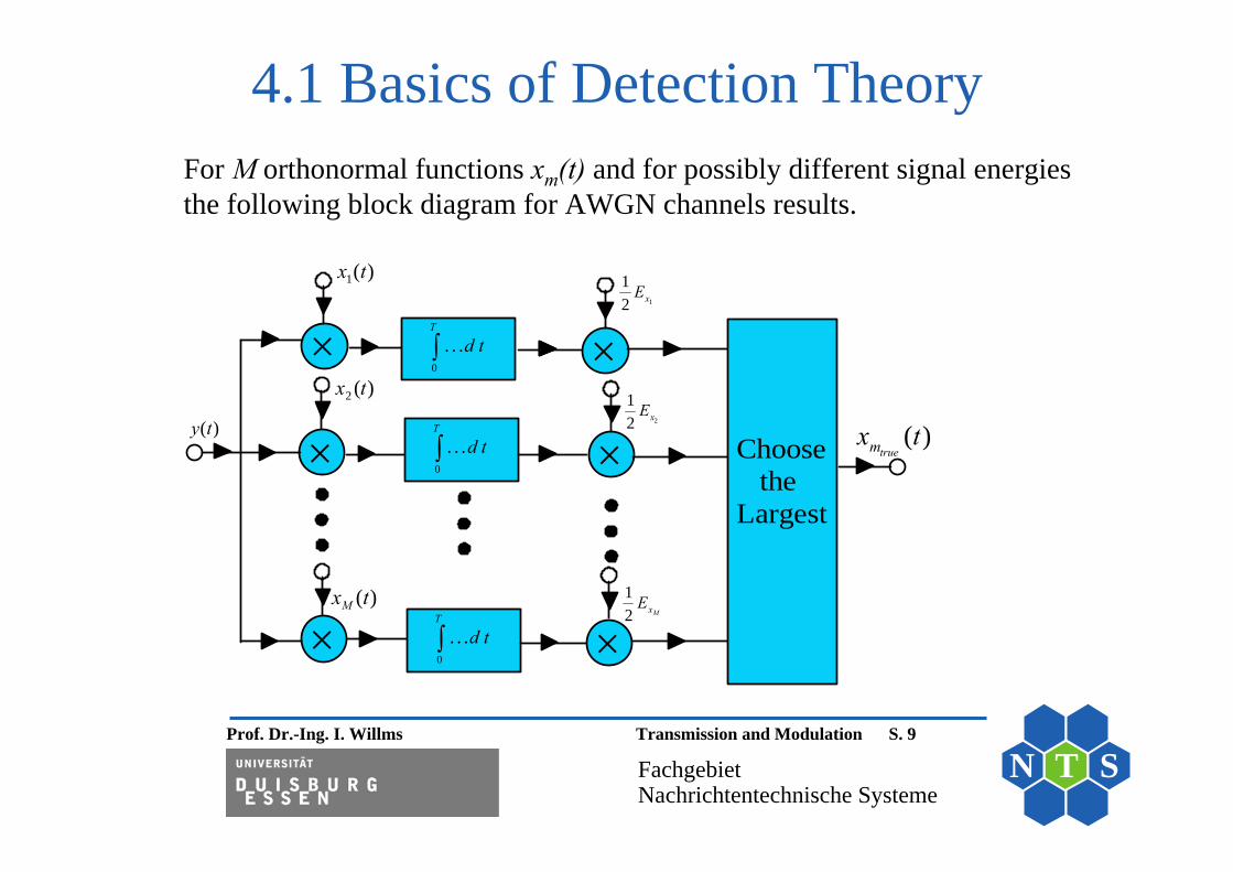
For M orthonormal functions xm(t) and for possibly different signal energiesthe following block diagram for AWGN channels results.
4.1 Basics of Detection Theory
0
. . .T
d t
0
. . .T
d t
0
. . .T
d t
Choose the Largest
1( )x t
2 ( )x t
( )Mx t
1
12 xE
2
12 xE
12 MxE
( )y t ( )truemx t

Prof. Dr.-Ing. I. Willms Transmission and Modulation S. 10
FachgebietNachrichtentechnische Systeme
N T S
Alternative method for realising the multiplication&integration:The operations are realised by a „matched“ filter.
4.1 Basics of Detection Theory
00
1 ( ) ( ) .T
x
Y y t x t dtE
00
00
1The operation replaces ( ) ( )
1 by ( ) ( ) with ( ) ( ) or h( ) ( )
T
x
T
x
Y y x dE
Y y h T d x h T x TE
00 0
This is achieved by a filter and sampling the output signal at :
1 1( ) ( ) ( ) ( ) ( )t T
t T t Tx x
t T
Y g t y h t d y h T dE E

Prof. Dr.-Ing. I. Willms Transmission and Modulation S. 11
FachgebietNachrichtentechnische Systeme
N T S
1 ( )x T t
Choose the Largest
1
12 xE
2
12 xE
12 MxE
( )y t( )y t
( )truemx t
2 ( )x T t
( )Mx T t
sample T = t
+
+
+
4.1 Basics of Detection Theory

Prof. Dr.-Ing. I. Willms Transmission and Modulation S. 12
FachgebietNachrichtentechnische Systeme
N T S
Chapter 4
Digital TM
4.2 Pulse Amplitude Modulation (PAM)
Mit freundlicher Unterstützung von Pearson-Studium –Die Abbildungen sind z.T. entnommen aus dem Buch
„Grundlagen der Kommunikationstechnik“von J.G. Proakis, M. Salehi

Prof. Dr.-Ing. I. Willms Transmission and Modulation S. 13
FachgebietNachrichtentechnische Systeme
N T S
Criteria for good transmission• Robustness concerning noise• Low bandwith usage• Low Tx power
4.2 PAM

Prof. Dr.-Ing. I. Willms Transmission and Modulation S. 14
FachgebietNachrichtentechnische Systeme
N T S
Transmission of data stream by amplitude modulated signals PAM with 0 and A as signal amplitude
• Bipolar (binary antipodal) with amplitudes –A and +A • Non binary PAM methods use M amplitude values
4.2 PAM
Binary and quaternary signals

Prof. Dr.-Ing. I. Willms Transmission and Modulation S. 15
FachgebietNachrichtentechnische Systeme
N T S
Binary Modulation• Each binary value corresponds to a signal with duration TD
• Thus no additional coding required
4.2 PAM
Non binary Modulation• L bits are combined to one symbol• Thus 2L symbols result • Transmission time for one symbol is TS = L * TD
• L less changes of signal levels• For equal maximum level L = 2L smaller amplitude values
need to be detected• Compromise of S/N ratio and bandwith usage is required

Prof. Dr.-Ing. I. Willms Transmission and Modulation S. 16
FachgebietNachrichtentechnische Systeme
N T S
4.2 PAM1 1 0 1 0 0 0 1 0 1 1 0
2 ASK BPSKBinary Modulation x t x t
DT
4 ASKQuaternary Modulation x t
S DT 2T
8 ASKOctonary Modulation x t
S DT 3T
d 2
d 2
d 23d 2
d 23d 25d 27 d 2
0

Prof. Dr.-Ing. I. Willms Transmission and Modulation S. 17
FachgebietNachrichtentechnische Systeme
N T S
Minimisation of bandwith usage • Avoiding of rectangular signal form due to si-form of spektrum• Alternatives of signal forms in time-domain: si-Function, Gauss function
4.2 PAM

Prof. Dr.-Ing. I. Willms Transmission and Modulation S. 18
FachgebietNachrichtentechnische Systeme
N T S
Bandpass signals• Modulation is typically required (matching channel properties)• Sequence of Gauss funktions form the signal in base band • Modulation of this signal by AM, PM or FM
4.2 PAM
Gauss signal and its Spectrum of baseband (a) andAM-Modulator AM signal (b)

Prof. Dr.-Ing. I. Willms Transmission and Modulation S. 19
FachgebietNachrichtentechnische Systeme
N T S
Chapter 4
Digital Transmission
4.3 Transmission usingorthogonal signals

Prof. Dr.-Ing. I. Willms Transmission and Modulation S. 20
FachgebietNachrichtentechnische Systeme
N T S
4.3 Transmission using orthogonal signals
Ein
• Extended example of S.8 with separation into sine and cosine functions and corresponding xm(t) functions
• Xim correspond to Fourier coefficients an and bn
0
1 0 0
2 01 0
0
01 1 1 0 00
1 0 00
( ) ( / - 0.5)cos( )
cos ( )2
2( ) ( ) / ( / - 0.5)cos( )
2( ) ( / - 0.5)cos( )
T
x
x
n
x t rect t T t
TE t dt
f t x t E rect t T tT
f t rect t T n tT
0 0( ) ( ) mit m 1, 2m m mx t X f t
0
2 0 0
2 02 0
0
02 2 2
2 0 00
( ) ( / - 0.5)sin( )
sin ( )2
( ) ( ) /
2( ) ( / - 0.5)sin( )
T
x
x
n
x t rect t T t
TE t dt
f t x t E
f t rect t T n tT

Prof. Dr.-Ing. I. Willms Transmission and Modulation S. 21
FachgebietNachrichtentechnische Systeme
N T S
M orthogonal functions xm(t) are used in detection
0
. . .T
d t
0
. . .T
d t
0
. . .T
d t
Choose the Largest
1( )x t
2 ( )x t
( )Mx t
1
12 xE
2
12 xE
12 MxE
( )y t ( )truemx t
4.3 Transmission using orthogonal signals

Prof. Dr.-Ing. I. Willms Transmission and Modulation S. 22
FachgebietNachrichtentechnische Systeme
N T S
Example for coding in the transmitter• For binary value “0” x1(t) is transmitted• For binary value “1” x2(t) is transmitted
2
0 0
1 1( ) ( ) = ( ) mit 1, 2m
m m
T T
K m m xt tx x
Y y t x t dt x t dt E mE E
For noise free transmission it results: • For binary value “0” : Y01 = YK > 0, Y02 = 0
• For binary value “1” : Y01 = 0, Y02 = YK > 0 with
4.3 Transmission using orthogonal signals
0 00 0
The value of
1( ) ( ) ( ) ( ) mit 1, 2
gives the criteria for choosing one hypothesism
T T
m m mt tx
Y y t f t dt y t x t dt mE

Prof. Dr.-Ing. I. Willms Transmission and Modulation S. 23
FachgebietNachrichtentechnische Systeme
N T S
Constellation diagram• The values Werte für Y01 und Y02 can be represented in a graphic for
good • Thus the degree of robustness can be figured out
Distance between marked points indicates degree of robustness against noise
02Y
01Y
K(0,Y )K(Y ,0)
4.3 Transmission using orthogonal signals

Prof. Dr.-Ing. I. Willms Transmission and Modulation S. 24
FachgebietNachrichtentechnische Systeme
N T S
Other orthogonal base band signals• Sine and cosine functions are
orthogonal• This also holds for sine/cosine
signals of n times the fundamental frequency
• Walsh functions are orthogonal• Other functions are known and can
be specified
2 examples of 4 orthogonal functions
4.3 Transmission using orthogonal signals

Prof. Dr.-Ing. I. Willms Transmission and Modulation S. 25
FachgebietNachrichtentechnische Systeme
N T S
Chapter 4
Digital TM
4.4 Quadrature AM

Prof. Dr.-Ing. I. Willms Transmission and Modulation S. 26
FachgebietNachrichtentechnische Systeme
N T S
4.4 QAMPrinciple of QAM• QM uses different amplitude and phase levels of the carrier• The number of M symbols depends on possibilities of combing
amplitude and phase levels
2 2
( ) cos( ) sin( )
cos( arctan( / ) mit 1, 2, ...
QAM m c m c
m m c m m
x t a t b t
a b t b a m M

Prof. Dr.-Ing. I. Willms Transmission and Modulation S. 27
FachgebietNachrichtentechnische Systeme
N T S
Example with 2 amplitude and 2 phase values• 4 different base band signals result• This QAM version can also be understood as phase shift keying
(4-PSK) verstanden werden• The constellation diagram describes here real and imaginary part
of the equivalent LP signal of the carrier
4.4 QAM
a) Constellationsdiagramm for M = 4
02Y
01Y
K(0, Y )
K( Y ,0)
K(0, Y )
K(Y ,0)
b) The same degree of robustness results for a rotated diagram, see next slide

Prof. Dr.-Ing. I. Willms Transmission and Modulation S. 28
FachgebietNachrichtentechnische Systeme
N T S
4.4 QAM4 Signals of the constellation diagram a) und b):
1
2
3
4
Zu a):( ) cos( ) ( / 0.5)( ) sin( ) ( / 0.5)( ) cos( ) ( / 0.5)( ) sin( ) ( / 0.5)
c
c
c
c
x t t rect t Tx t t rect t Tx t t rect t Tx t t rect t T
1
2
3
Zu b):
( ) 1 / 2(cos( ) sin( )) ( / 0.5) cos( / 4) ( / 0.5)
( ) 1 / 2( cos( ) sin( )) ( / 0.5) cos( 3 / 4) ( / 0.5)
( ) 1 / 2( cos( ) sin( )) ( / 0.5)
c c c
c c c
c c
x t t t rect t T t rect t T
x t t t rect t T t rect t T
x t t t rect t T
4
cos( 3 / 4) ( / 0.5)
( ) 1 / 2(cos( ) sin( )) ( / 0.5) cos( / 4) ( / 0.5)
c
c c c
t rect t T
x t t t rect t T t rect t T

Prof. Dr.-Ing. I. Willms Transmission and Modulation S. 29
FachgebietNachrichtentechnische Systeme
N T S
0 1 1 0 0 1
k
4 PSKx t
i,4 PSKx t
q,4 PSKx t
/ 4
1
1
1
1
1
1
3 45 47 4
t
t
t
t
k

Prof. Dr.-Ing. I. Willms Transmission and Modulation S. 30
FachgebietNachrichtentechnische Systeme
N T S
4.4 QAMAdditional extensions for M > 4• Additional amplitude and phase levels give more symbols
Constellation diagram for M = 16
0
0
Example for M = 16 ( ) ( 5 / 3 2 / 3) ( / - 0.5) cos( ) 1 4( ) ( 5 / 3 2 / 3) ( / - 0.5) sin( ) 5 8
i c
i c
x t i rect t T t ix t i rect t T t i

Prof. Dr.-Ing. I. Willms Transmission and Modulation S. 31
FachgebietNachrichtentechnische Systeme
N T S
• The graphics show the constellation diagrams for comparison of 4-ASK and 8-ASK
4.4 QAMM=4
00 10 11 011x 2x 3x 4x
33 1 1M=8
000 101001 100 110 111 011 0101x 2x 3x 4x 5x 6x 7x 8x
5 711357 3

Prof. Dr.-Ing. I. Willms Transmission and Modulation S. 32
FachgebietNachrichtentechnische Systeme
N T S
Further variants• In principle there is no limit for the
number of symbols • Different constellation diagrams can
be selected• Large M values lead to high
sensitivity to noise• Reason: Low distances between
points in constellation diagram
4.4 QAM

Prof. Dr.-Ing. I. Willms Transmission and Modulation S. 33
FachgebietNachrichtentechnische Systeme
N T S
4.4 QAM
Modulator for QAM The 2 filters specify the behaviour of impulses in time domain

Prof. Dr.-Ing. I. Willms Transmission and Modulation S. 34
FachgebietNachrichtentechnische Systeme
N T S
Receiver for QAM signals
4.4 QAM

Prof. Dr.-Ing. I. Willms Transmission and Modulation S. 35
FachgebietNachrichtentechnische Systeme
N T S
Chapter 4
Digital TM
4.5 PSK and FSK

Prof. Dr.-Ing. I. Willms Transmission and Modulation S. 36
FachgebietNachrichtentechnische Systeme
N T S
Principles for PSK/FSK• Constant amplitude for all symbols bei suitable modulation
of I/Q carrier • Constellation diagram thus always includes a circle• Again distance of points corresponds to robustness
4.5 PSK and FSK
Constellation diagrams for different number of symbols for PSK

Prof. Dr.-Ing. I. Willms Transmission and Modulation S. 37
FachgebietNachrichtentechnische Systeme
N T S
Properties• Similar to PM/FM of analog signals (e,g. conc. power efficiency)• Problem: Jumps due to chnges in the phase enlarge the bandwidth
4.5 PSK and FSK
Modulated carrier signal for M = 4 (4-PSK or QPSK)

Prof. Dr.-Ing. I. Willms Transmission and Modulation S. 38
FachgebietNachrichtentechnische Systeme
N T S
4.5 PSK and FSKGray-Coding• In principle freedom is given conceerning relation of
coed and symbols• Gray coding reduces also here bit errors
Example for a relation of bit combinations and phase values of the modulated carrier
for D n 0 and D n 1 043 for D n 1and D n 1 04k5 for D n 1and D n 1 14
7 for D n 0 and D n 1 14
Prof. Dr.-Ing. I. Willms Transmission and Modulation S. 39
FachgebietNachrichtentechnische Systeme
N T S
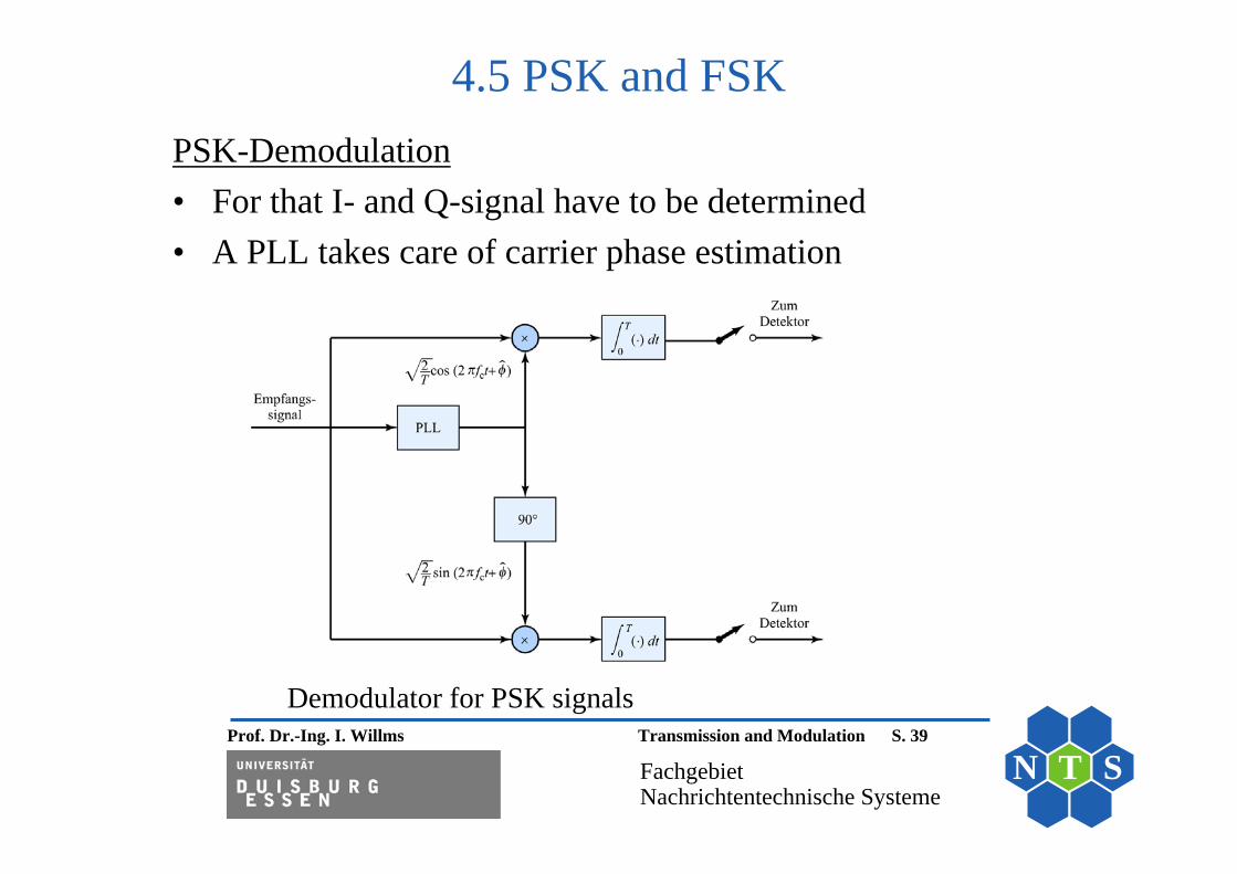
PSK-Demodulation• For that I- and Q-signal have to be determined• A PLL takes care of carrier phase estimation
4.5 PSK and FSK
Demodulator for PSK signals

Prof. Dr.-Ing. I. Willms Transmission and Modulation S. 40
FachgebietNachrichtentechnische Systeme
N T S
Offset-PSK• Phase changes lead to short-time drop of carrier amplitude• An “offset” (delay ) between I- and Q-Signal prevents this
4.5 PSK and FSK
Possible signal changes of 4-PSK Signal changes of offset-PSK
12
3 4
d2
d2
d2
d2
1f
0f
d2
d2
d2
d2

Prof. Dr.-Ing. I. Willms Transmission and Modulation S. 41
FachgebietNachrichtentechnische Systeme
N T S
0 1 1 0 0 1
4
d2
d2
d 2
d 2
d 2
d 2
3 45 47 4
t
t
t
t
k
k
4 OPSKx t
i,4 OPSKx t
q,4 OPSKx t
DT
Prof. Dr.-Ing. I. Willms Transmission and Modulation S. 42
FachgebietNachrichtentechnische Systeme
N T S
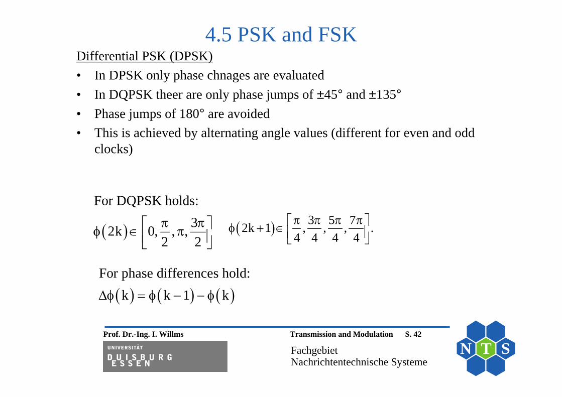
4.5 PSK and FSKDifferential PSK (DPSK)• In DPSK only phase chnages are evaluated • In DQPSK theer are only phase jumps of ±45° and ±135°• Phase jumps of 180° are avoided• This is achieved by alternating angle values (different for even and odd
clocks)
For phase differences hold:
k k 1 k
For DQPSK holds:32k 0, , ,
2 2
3 5 72k 1 , , , .4 4 4 4
Prof. Dr.-Ing. I. Willms Transmission and Modulation S. 43
FachgebietNachrichtentechnische Systeme
N T S
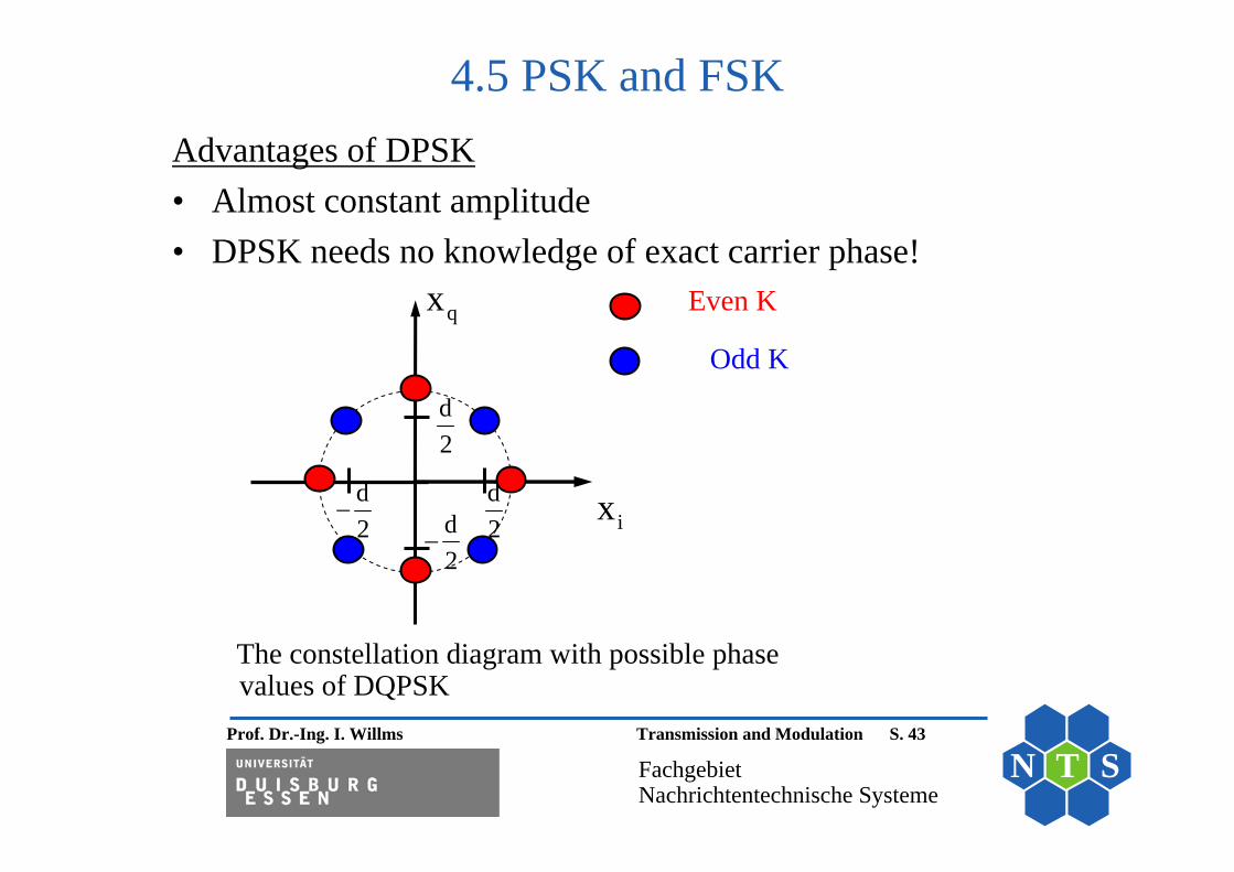
Advantages of DPSK• Almost constant amplitude• DPSK needs no knowledge of exact carrier phase!
4.5 PSK and FSK
The constellation diagram with possible phase values of DQPSK
qx
ix
d2
d2d
2
d2
Even K
Odd K

Prof. Dr.-Ing. I. Willms Transmission and Modulation S. 44
FachgebietNachrichtentechnische Systeme
N T S
4.5 PSK and FSKFSK signals• Modulation comparable to FM• In FSK also phase jumps can happen due to symbol changes• Only discrete frequencies are transmitted• Signals are almost orthogonal • Für Tx signal (with non-symmetrical frequency bands with
regard to carrier frequency holds:
By changing of frequencies by (M-1)ωd /2 a symmetrical spektrum can berealised.
Sm C d m
S
d
t T 2x t cos m t rectT
with as minimum difference frequency and m = 0, 1, ... M-1

Prof. Dr.-Ing. I. Willms Transmission and Modulation S. 45
FachgebietNachrichtentechnische Systeme
N T S
4.5 PSK and FSK
The first expression drops close to zero for large argument, the second expression is zero for:
Orthogonality property of FSK signals• Here 2 signals of different symbols are tested for
othogonalityt• This test leads to:
m kx t x t dt
ST
C d C d0
cos m t cos k t dt
C d SS
C d S
sin 2 m k TT2 2 m k T
S ST T
C d d0 0
1 1cos 2 m k t dt cos 2 m k t dt2 2
d SS
d S
sin 2 m k TT .2 2 m k T
dS
.2T

Prof. Dr.-Ing. I. Willms Transmission and Modulation S. 46
FachgebietNachrichtentechnische Systeme
N T S
Demodulation of M-FSK signals
4.5 PSK and FSK

Prof. Dr.-Ing. I. Willms Transmission and Modulation S. 47
FachgebietNachrichtentechnische Systeme
N T S
4.5 PSK and FSKContinuos PSK and FSK• An FSK modulator can be realised by switching M different
oszillators• Avoiding phase jumps reduces bandwidth• The same holds for jumps of instantanous frequency• Realisation by memories and by• Continuos phase jumps

Prof. Dr.-Ing. I. Willms Transmission and Modulation S. 48
FachgebietNachrichtentechnische Systeme
N T S
4.5 PSK and FSK
Carrier phase for binary CPFSK
• Points in constellation diagram moves with time!
• FSK gives movement at constant radius
• In CPFSK phase does not jump
• Shown points represent state at end of a clock

Prof. Dr.-Ing. I. Willms Transmission and Modulation S. 49
FachgebietNachrichtentechnische Systeme
N T S
4.5 PSK and FSK
Carrier phase for quaternary CPFSK

Prof. Dr.-Ing. I. Willms Transmission and Modulation S. 50
FachgebietNachrichtentechnische Systeme
N T S
4.5 PSK and FSKMSK signals (Special case of CPFSK)• Orthogonality for smallest frequency change is looked for• 2 equivalent LP carrier signal s are consideerd• Phase values at end of the clock are mI times of π
I I
S S
m mj t j tT T
T1 T2x t e x t e
S S
I
T T !2 j m*T1 T2 T1 S I
0 0
Due to complex valued LP signals holds:
x t x t dt x t dt T e si 2 m 0 I
1m is minimum value for orthogonality2
S
dS
Phasen rising about /2 in period T
gives instantaneous frequency of .2T

Prof. Dr.-Ing. I. Willms Transmission and Modulation S. 51
FachgebietNachrichtentechnische Systeme
N T S
4.5 PSK and FSK
a) I-Signal (real part of equiv. LP signal of MSK-modulated carrier)b) Q-Signal (imaginary part of it)c) MSK-Signal

Prof. Dr.-Ing. I. Willms Transmission and Modulation S. 52
FachgebietNachrichtentechnische Systeme
N T S
Power spectrum desnity of MSK compared to offset QPSK [Gronemeyer und McBride, 1976]
4.5 PSK and FSK

Prof. Dr.-Ing. I. Willms Transmission and Modulation S. 53
FachgebietNachrichtentechnische Systeme
N T S
4.5 PSK and FSKGMSK signals• Also MSK still produces frequency jumps• Further reduction of bandwidth results by LP filterung• A Gaussian filter is typically used
For its impulse response holds:
2
g
ln 22
GAUSS g
Transfer function of this filter:
H e with as cut-off frequency
2gt
g 2ln 2GAUSSh t e
2 ln 2

Prof. Dr.-Ing. I. Willms Transmission and Modulation S. 54
FachgebietNachrichtentechnische Systeme
N T S
4.5 PSK and FSK
Impulse response of Gaussian filters for different cut-off frequencies with ω3dB = ωg

Prof. Dr.-Ing. I. Willms Transmission and Modulation S. 55
FachgebietNachrichtentechnische Systeme
N T S
4.5 PSK and FSK
Comparison of phase of binary MSK and GMSK
0 1 1 0 0 1
MSK GMSK
t
t
GMSK t
DT
2
2

Prof. Dr.-Ing. I. Willms Transmission and Modulation S. 56
FachgebietNachrichtentechnische Systeme
N T S
4.5 PSK and FSK
Application of GMSK in mobile phones

Prof. Dr.-Ing. I. Willms Transmission and Modulation S. 57
FachgebietNachrichtentechnische Systeme
N T S
Chapter 4
Digital Transmission
4.6 Aspects of Symbol Interference

Prof. Dr.-Ing. I. Willms Transmission and Modulation S. 58
FachgebietNachrichtentechnische Systeme
N T S
4.6 SymbolinterferenzRelation bandwidth to data rate• For the AWGN situation an optimal matched filter reception is
assumed (see chap. 4.1)• ASK is the chosen transmission method
00
Without noise with ( ) ( ) for each symbol the value
1 ( ) ( ) = with ( ) ( ) is determined which corresponds to filtering
(correlation) of the signal ( ) with ( ) ( - ) .
For a sym
T
x
y t x t
Y y h T d x t h T tE
y t y t x T t
0 0
bol sequence ( ) at the matched filter output the signal results:
( ( ) ( - )) * ( - ) ( ) ( - - ) with the ACF ( ) ( ) ( )xx xxk k
S k
S k x t kT x T t S k t T kT t x x t d
Prof. Dr.-Ing. I. Willms Transmission and Modulation S. 59
FachgebietNachrichtentechnische Systeme
N T S
4.6 Symbolinterferenz
0 0
xx xx xxk 0
xx xx xx xx
S(k) (k) (k 1) For that the following output signals result:
S(k) (t - T - kT) S(0) (t - T) S(1) (t - 2T)
For the sample values therefore hold:At t T: S(k) (T - T) (T 2T) (0) (-T)
At
xx xx xx xx t 2T: S(k) (2T - T) (2T 2T) (T) (0)
Due to sampling the following sequence of values results:
xxk 0
xx xx
S(k) ( kT)
For preventing an overlapping of neighboured symbol values (i.e. no symbol interference) and because of the even ACF it must hold:
( kT) (kT) 0 k 0 (1st Nyquist criteria)
Example: Binary sequence with only 2 non-zero values

Prof. Dr.-Ing. I. Willms Transmission and Modulation S. 60
FachgebietNachrichtentechnische Systeme
N T S
4.6 Symbolinterferenz
Possible ACF’s:• Signals limited to symbol duration such as the rect-funktion• Rectangular signals give a ACF’s in triangular form• Disadvantage: For a perfect transmission in principle an infinitely
large bandwidth is needed• The ideal frequency limited signal is the si function • Disadvantage of the si function: Symbol interference in case of
unprecise sampling points
xx S
g
t Tsi( t / T )
This signal demands a bandwidth of (50% of the clock rate)T
Prof. Dr.-Ing. I. Willms Transmission and Modulation S. 61
FachgebietNachrichtentechnische Systeme
N T S
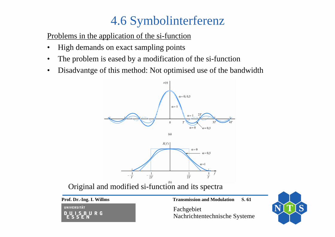
4.6 Symbolinterferenz Problems in the application of the si-function• High demands on exact sampling points• The problem is eased by a modification of the si-function • Disadvantge of this method: Not optimised use of the bandwidth
Original and modified si-function and its spectra

Prof. Dr.-Ing. I. Willms Transmission and Modulation S. 62
FachgebietNachrichtentechnische Systeme
N T S
4.6 Symbolinterferenz Other effects• In practice non-ideal channels are often given with strong changes in the
frequency response – even in the case of transmission at a small bandwidth
• This has similar effects as a non-si-form of the ACF• Counter measure: Application of a bandwith efficient method called
“Orthogonal Frequency Division Multiplex” (OFDM)• Basic idea: Separation of the whole channel into many sub-channels with
a constant frequency response and equal bandwidth

Prof. Dr.-Ing. I. Willms Transmission and Modulation S. 63
FachgebietNachrichtentechnische Systeme
N T S
4.6 Symbolinterferenz FSK signals in the subchannels• All K subchannels will be used simultaneously• Each subchannel has its own carrier• The symbolrate and the corresponding period T = KTS of each subchannel
will be adjusted to the K-times lower bandwidth (in comparison to the transmission without OFDM)
• Also the different S/N ratios can be taken into account
For K > 25 in the Tx and Rx devices FFT algorithms are applied instead of a bank of band-pass filters..
k k m
T
k k i i0
Carriers in the k's subchannel:x t cos t with k 0,1, ... K -1All carriers are orthogonal to each other due to:
cos t cos t dt 0 i k

Prof. Dr.-Ing. I. Willms Transmission and Modulation S. 64
FachgebietNachrichtentechnische Systeme
N T S
Block diagram of an OFDM transmission system
4.6 Symbolinterferenz