Embed Size (px)
Citation preview

Improving Signal Integrity through Advanced Probe Card Design and Advanced Probe Card Metrology
Jeff ArasmithCascade Microtech
Jeff GreenbergJohn Strom
Rudolph Technologies

Introduction• Trends
– Advanced packages– Shrinking technology nodes– More RF
• Details of Cascade Microtech probe cards– Pyramid Probe– RBI
• Need for Metrology• Metrology Challenges• Metrology methods for Cascade Microtech probe cards
– Pyramid Probe– RBI
2Arasmith, Greenberg, Strom

Trends – Advanced Package• Trend – Advanced packages
– 3D‐TSV for 3D die stacks• Wide I/O memory interface
– 2.5D packages• Challenges
– 40 and 50 µm pitch arrays– Large arrays
• Pyramid Probe® response– Photolithographically defined probe tips in a membrane space transformer
– Rocking Beam Interposer demonstrated at imec
3Arasmith, Greenberg, Strom

Trends – Smaller Technology Nodes• Trend – Shrinking technology nodes
– More content per unit area of the die
• Challenges– More I/O– Finer pitch
• Pyramid Probe® response– Membrane space transformer
• Fine pitch array routing capabilities
4Arasmith, Greenberg, Strom
Source: IEEE Spectrum

Trends – More RF• Trend – More RF
– More integration results in more RF ports per DUT– Higher frequency bands being used
• 5 GHz 802.11ac• 60 GHz 802.11ad and backhaul• 80 GHz Automotive radar
• Challenges– Impedance control on supplies and transmission lines– Probe inductance
• Pyramid Probe® response– Membrane space transformer– Short probe tips
5Arasmith, Greenberg, Strom

Pyramid Probe
• Membrane space transformer– Two layers for impedance control and low inductance power and ground • 0.04 nH probe tip
– Finer pitch routing than ceramics or packages
6Arasmith, Greenberg, Strom

Pyramid Probe
• Probe Tips– Positioned photolithographically to access smaller pads and finer pitches• 35 µm pads and 50 µm pitch with <5 µm scrub• 15 µm µbump on 40 x 50 µm array demonstrated for RBI
– Short for low inductance and smaller scrub marks• 0.04 nH probe tip inductance
7Arasmith, Greenberg, Strom

Rocking Beam Interposer (RBI)• A demonstrated technology in development for an emerging industry
8Arasmith, Greenberg, Strom
RBI coupon Single RBIPPST
PlungerPCB PCB

Rocking Beam Interposer• Addressing the Challenges of Testing Wide IO Microbumps– Softer springs
• Contact without damage• 1 gram at overtravel
– Smaller probe tips• Higher density routing like the Wide I/O memory interface
– Membrane space transformer• Clean power delivery• Power and GND with wider traces• Bypass caps on the membrane
9Arasmith, Greenberg, Strom

Pyramid Probe Coupled System• Probe Card Compliance– Membrane connected to PCB by a spring
– 10 g per tip at 150 µm overdrive• 0.067 g/µm per tip• 1.7 g/mil per tip
10Arasmith, Greenberg, Strom

Pyramid Probe Coupled System• Probe card compliance– Membrane connected to PCB by a spring
– 10 g per tip at 150 µm overdrive• 0.067 g/µm per tip• 1.7 g/mil per tip
• Plunger spring– Force between tip and DUT
– One spring shared by all the tips
11Arasmith, Greenberg, Strom

Pyramid Probe Coupled System• Probe tip compliance– Membrane attached to plunger with compliant adhesive layer
– About 2 g/µm per tip• 50 g/mil per tip
• Tip spring – MicroScrub®– Local compliance
12Arasmith, Greenberg, Strom

Pyramid Probe Coupled System• Model with series and parallel springs
• For a single tip, just series springs
13Arasmith, Greenberg, Strom
kplunger
ktip

Pyramid Probe Coupled System• Model with series and parallel springs
• For a single tip, just series springs
14Arasmith, Greenberg, Strom
kplunger
ktip
Source: Wikipedia

Pyramid Probe Coupled System
15Arasmith, Greenberg, Strom
kplunger
ktip
• Series springs– kplunger = 0.067 g/µm per tip– ktip = 1.9 g/µm per tip
• Programmed OT = 150 µm– Plunger 145 µm– Tip 5 µm
Ftotal = ktotal*xFtotal = Fplunger = Ftip
Ftotal = ktip*xtipxtip = Ftotal / ktip
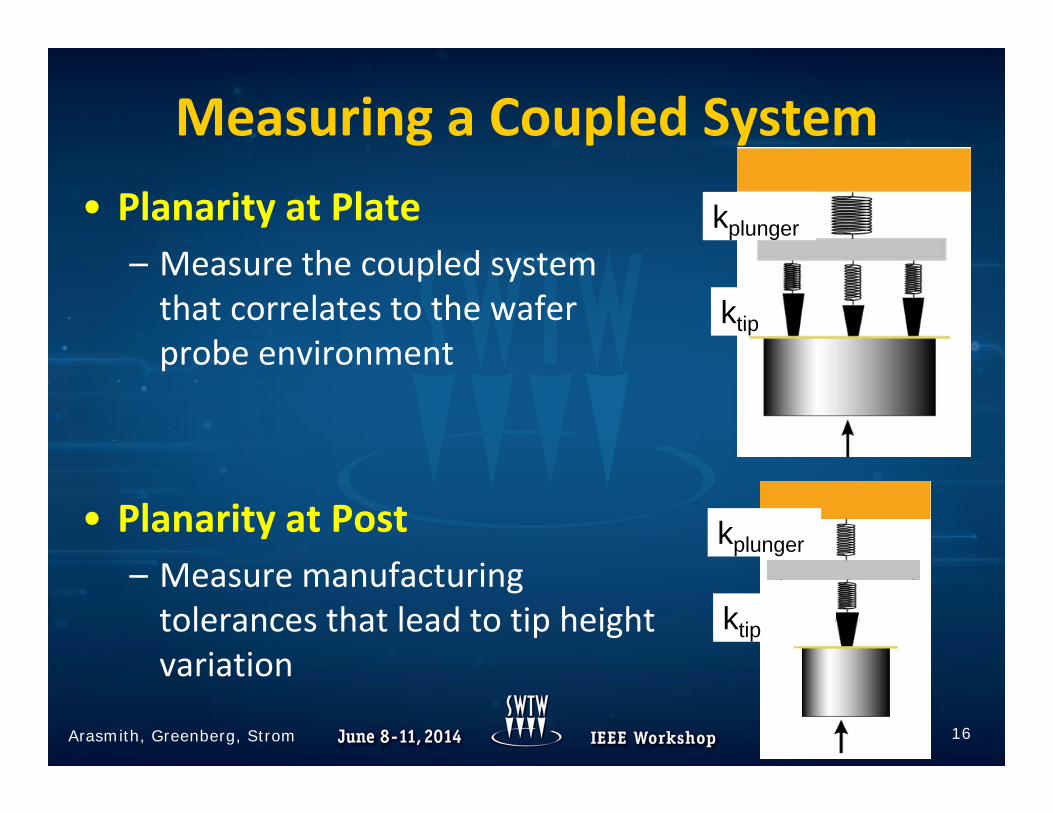
Measuring a Coupled System• Planarity at Plate
– Measure the coupled system that correlates to the wafer probe environment
• Planarity at Post – Measure manufacturing tolerances that lead to tip height variation
16Arasmith, Greenberg, Strom
kplunger
ktip
kplunger
ktip

Need for Metrology• Internal
– Manufacturing/Quality• X,Y• Planarity• Contact resistance• Leakage
– Engineering• Don’t try this at home
• Customer– IQC– Troubleshooting
• X,Y• Planarity• Contact resistance• Leakage
17Arasmith, Greenberg, Strom

Metrology Challenges• Membrane space transformer
– Coupled system – tip to tip• Requirement for full contact or small deflection
– Coupled system – spring stack• Unconventional spring rates
– Over travel control– Force control
• Short probe tips– Short
• Vision system• Over travel control• Force control
• Mechanical vs. Electrical Trade‐offs– Easy to measure bulk behavior with a plate– Challenges when measuring with a post
18Arasmith, Greenberg, Strom

Metrology Challenges Summary• Pyramid Probe Cards
– Very strong probe tip spring (1‐4 grams/micron)
– Individual probe tip overtravel (OT) must be limited to 20 microns– Coupled system of probe tip springs and plunger spring– No overhanging probes during overtravel
• RBI Probe Cards– Individual probe tip overtravel (OT) must be limited to 5 microns– Coupled system of probe tip springs and plunger spring– No overhanging probes during overtravel– Small probe tips surrounded by visible structure (grainy beams, posts,
traces, pads)– Short probe tips so surrounding structure is close to probe tip focus plane
19Arasmith, Greenberg, Strom

Test Setup• Pyramid Probe Cards
– Parametric probe cards– 30 probes– 100‐150 micron minimum pitch– Spring rates ~= 1.3gm/um, 1.9gm/um
• RBI Probe Card– Microbump probe card– ~100 probes, limited electrical connections– 40 micron minimum pitch– Spring rate ~= 0.3 gm/um
• VX4 – Configured with 35 micron diameter posts
20Arasmith, Greenberg, Strom

Planarity @ Plate Measurement (non‐bussed probes)
Pyramid and RBI Probe Cards• Easy!• Coupled system of springs
– May need large Max OT in order for high probes to contact checkplate
21Arasmith, Greenberg, Strom

Planarity @Post Measurement (all probes)
Pyramid and RBI Probe Cards• Pyramid Probe individual probe tip MaxOT = 20 microns• RBI individual probe tip MaxOT = 5 microns
– Utilize post attached to load cell for measurement– Provides two layers of safety for Z‐motion:
• Stop on electrical contact• Stop on load
– Planarity is measured by either electrical contact or force– Requires ultra‐precise overshoot control to maintain throughput
– RBI Fine Pitch (40 microns)– Small diameter post required– Accurate post position calibration, accurate stage positioning and accurate
measurement of probe tip positions
22Arasmith, Greenberg, Strom

Planarity@ Plate Results – Pyramid Probe Card
• Correlates to when probes will contact wafer• Planarity range ~= 40 microns
23Arasmith, Greenberg, Strom
Planarity @Plate (non-bussed probes)

• Corresponds to tip height variation• Planarity range ~= 3 microns
Planarity @Post Results – Pyramid Probe Card
24Arasmith, Greenberg, Strom
Planarity @Post

Planarity Comparison – Pyramid Probe Card
• Compare Planarity @Plate to Planarity @Post• Same shape, different ranges due to effects of coupled system
25Arasmith, Greenberg, Strom
Plate Post
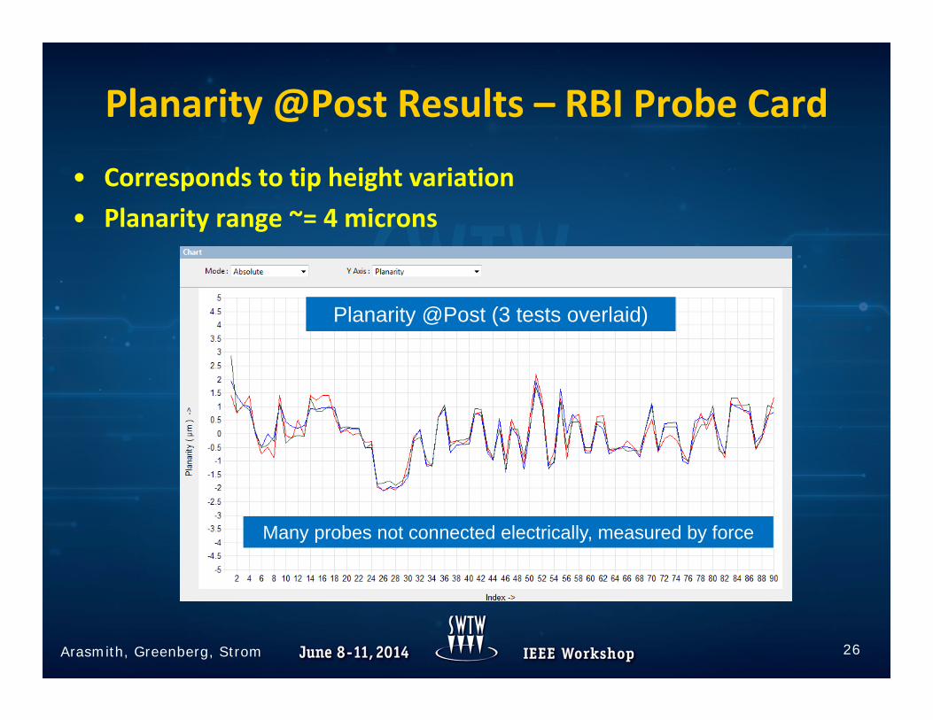
• Corresponds to tip height variation• Planarity range ~= 4 microns
Planarity @Post Results – RBI Probe Card
26Arasmith, Greenberg, Strom
Planarity @Post (3 tests overlaid)
Many probes not connected electrically, measured by force
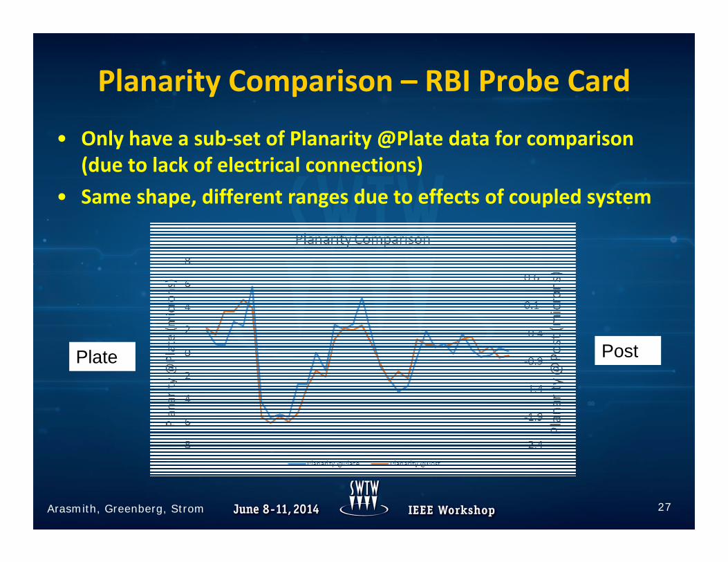
Planarity Comparison – RBI Probe Card
• Only have a sub‐set of Planarity @Plate data for comparison (due to lack of electrical connections)
• Same shape, different ranges due to effects of coupled system
27Arasmith, Greenberg, Strom
Plate Post

Alignment Measurement: Pyramid Probe Cards
• Probe array must be fully supported• Probe tips have minimal scrub at OT
– Measure X, Y probe position without contacting probe tips with focus position well above window surface (No‐Touch Alignment)
28Arasmith, Greenberg, Strom

Alignment Results – Pyramid Probe Card
Pyramid Probe Card
29Arasmith, Greenberg, Strom
X Position Error (5 tests overlaid)
Y Position Error (5 tests overlaid)
• Very repeatable Alignment results (sub-micron)

Alignment Measurement : RBI Probe Cards
• RBI has small probe tips and lots of in focus visible structure surrounding probe tips (grainy beams, posts, traces, pads) – Live Image Viewer provides in real‐time tunable image processing to
discriminate probe tips from background
30Arasmith, Greenberg, Strom

Alignment Measurement : RBI Probe Cards
• Using Live Image Viewer to tune image processing parameters in real‐time
31Arasmith, Greenberg, Strom

RBI Probe Card
Alignment Results – RBI Probe Card
32Arasmith, Greenberg, Strom
X Position Error (3 tests overlaid)Y Position Error (3 tests overlaid)
• Very repeatable Alignment results (sub-micron)

• Large probe tip spring rate (1–4 gm/um)– Probe force measurement uses a compliant load cell
– Need to compensate for load cell deflec on (AOT ≠ POT) to get accurate probe force measurements
– Load cell spring is typically > 5X stiffer than probe tip
• Pyramid probe tip spring can be 5X stiffer than load cell spring– Without compensation Pyramid Probe tip AOT << POT during PF testing– Accurate deflection compensation is critical for Pyramid Probes
Probe Force Measurement: Pyramid Probe Cards
33Arasmith, Greenberg, Strom
Load cell
Typicalprobe tip
Pyramidprobe tip
Load cell

• Probe force is very uniform across the array• Probe tip spring is very linear • Load cell compensation working effectively
Probe Force Results – Pyramid Probe Card
34Arasmith, Greenberg, Strom
Probe Force vs OTAll probes0-20um OT1um steps
Force vs Probe Tip ID 0-20um OT, 1um steps

Probe Force Measurement: RBI Probe Cards
• RBI individual probe tip MaxOT = 5 microns– Two layers of safety for Z‐motion:
• Stop on electrical contact and stop on load
– Requires ultra‐precise overshoot control to maintain throughput– Requires high resolution z‐motion to collect data over small range of
allowed overtravel– Requires high precision force measurement to measure small changes in
force over small range of allowed overtravel
– RBI Fine Pitch (40 microns)– Requires small diameter post (35 micron)– Accurate post position calibration, accurate stage positioning and accurate
measurement of probe tip positions
35Arasmith, Greenberg, Strom

• Results demonstrates precision force measurement to resolve the small changes in force (0.5 grams over 2.5 microns OT)
• Results demonstrate high resolution z‐motion (100nm steps) needed to characterize force over this small range of OT
Probe Force Results – RBI Probe Card
36Arasmith, Greenberg, Strom
Probe Force vs OT0 - 2.5 microns OT0.1 micron steps

Contact Resistance Measurement
Pyramid and RBI Probe Cards• CRES @Plate (Non‐bussed probes)
– Easy!– Need to provide sufficient overtravel to ensure all probes make good
contact
• CRES @Post (All probes)– Need to provide additional overtravel so AOT = POT for Pyramid probes– Need to provide ultra‐precise OT and overshoot control for RBI probes
37Arasmith, Greenberg, Strom

CRES with W‐C Post: 0‐10umStep size = 0.1 microns
CRES Results– Pyramid Probe Card
CRES with Rh Plate: 0‐70um Step size = 2 microns
38Arasmith, Greenberg, Strom
Values includes path resistance of both probe card and probe card analyzer
• Excellent contact performance– CRES values stabilize almost immediately after initial contact

CRES Results– RBI Probe Card
CRES with Tungsten‐Carbide Post0‐2 microns OT, Step size = 0.2 microns
• CRES values stabilize almost immediately after initial contact• Extremely high resolution Z‐motion needed to characterize tip resistance over this range of OT
39Arasmith, Greenberg, Strom
Summary• Pyramid Probe and RBI are well poised to meet industry trends
– Advanced packages– Shrinking technology nodes– More RF
• Pyramid Probe and RBI provide unique metrology challenges• VX4 able to meet metrology challenges of Pyramid Probe and RBI and
successfully measure:– Planarity at Plate (Non‐bussed probes)– Planarity at Post (all probes)– Alignment– Contact Resistance at Plate (Non‐bussed probes)– Contact Resistance at Post (all probes)– Probe force
40Arasmith, Greenberg, Strom

Acknowledgements• Jim Powell – Rudolph Technologies• Brett Strong – Rudolph Technologies
41Arasmith, Greenberg, Strom

References• Ken Smith, Daniel Bock. “Signal Integrity Design for Wide IO and
3D‐TSV IC Test at Wafer Probe” Fourth IEEE International Workshop on Testing Three‐Dimensional Stacked Integrated Circuits Anaheim, CA Sept 13, 2013
• Ken Smith, Erik Jan Marinissen (2014, Jan‐Feb) Probing 25μm‐diameter micro‐bumps for Wide‐I/O 3D SICs. Chip Scale Review, Volume 18, Number 1, pp. 20‐23
42Arasmith, Greenberg, Strom