Embed Size (px)
Citation preview
1036.5015.12-08- 1
Test and MeasurementDivision
Operating Manual
SIGNAL GENERATOR
SMP1035.5005.02/03/04/22
Printed in the FederalRepublic of Germany


SMP Tabbed Divider Overview
1036.5015.12 RE E-1
Tabbed Divider Overview
Contents
Data Sheet
Safety InstructionsCertificate of qualityEC Certificate of ConformityList of R & S Representatives
Tabbed Divider
1 Chapter 1: Preparation for Use
2 Chapter 2: Manual Operation
3 Chapter 3: Remote Control
4 Chapter 4: Maintenance
5 Chapter 5: Performance Test
6 Annex A: Interfaces
7 Annex B: List of Error Messages
8 Annex C: List of Commands (with SCPI Conformity Information)
9 Annex D: Programming Example
10 Index


SMP Contents
1036.5015.12 3 E-8
Contents
1 Preparation for Use ........................................................................................... 1.1
1.1 Putting into Operation............................................................................................................ 1.1
1.1.1 Supply Voltage .................................................................................................................. 1.11.1.2 Power Fuses ..................................................................................................................... 1.11.1.3 Switching On/Off the Instrument ....................................................................................... 1.11.1.4 Initial Status....................................................................................................................... 1.21.1.5 Setting Contrast and Brightness of the Display................................................................. 1.21.1.6 RAM With Battery Back-Up............................................................................................... 1.21.1.7 Preset Setting.................................................................................................................... 1.3
1.2 Functional Test ....................................................................................................................... 1.3
1.3 Fitting the Options.................................................................................................................. 1.4
1.3.1 Opening the Casing........................................................................................................... 1.41.3.2 Overview of the Slots ........................................................................................................ 1.51.3.3 Option SM-B1 - Reference Oscillator OCXO .................................................................... 1.51.3.4 Option SM-B2 - LF Generator ........................................................................................... 1.61.3.5 Option SM-B5 - FM/PM Modulator .................................................................................... 1.71.3.6 Option SMP-B11 - Frequency Range Extension 0.01 to 2 GHz........................................ 1.71.3.7 Options SMP-B12 - Pulse Modulator 2 to 20 / 2 to 27 / 2 to 40 GHz ................................ 1.71.3.8 Options SMP-B13 - Pulse Modulator 0.01 to 2 GHz ......................................................... 1.71.3.9 Option SMP-B14 - Pulse Generator .................................................................................. 1.81.3.10 Options SMP-B15/B17 - Attenuator 20 GHz / 40 GHz ...................................................... 1.81.3.11 Option SMP-B18 - Auxiliary Interface................................................................................ 1.81.3.12 Option SMP-B19 /SMP-B20 - Rear Panel Connections for RF and LF............................. 1.9
1.4 Mounting into a 19" Rack ...................................................................................................... 1.9
2 Operation............................................................................................................ 2.1
2.1 Explanation of Front and Rear Panel.................................................................................... 2.1
2.1.1 Elements of the Front Panel.............................................................................................. 2.12.1.1.1 Display ........................................................................................................................... 2.12.1.1.2 Controls ......................................................................................................................... 2.32.1.1.3 Inputs/Outputs ............................................................................................................. 2.11
2.1.2 Elements of the Rear Panel ............................................................................................ 2.13
2.2 Operating Concept ............................................................................................................... 2.18
2.2.1 Display............................................................................................................................. 2.182.2.2 Basic Operating Steps..................................................................................................... 2.19
2.2.2.1 Calling the Menus ........................................................................................................ 2.192.2.2.2 Selection and Change of Parameters.......................................................................... 2.202.2.2.3 Triggering Action.......................................................................................................... 2.212.2.2.4 Quick Selection of Menu (QUICK SELECT)................................................................ 2.212.2.2.5 Use of [FREQ] and [LEVEL] Keys ............................................................................... 2.222.2.2.6 Use of [RF ON / OFF] and [MOD ON / OFF] Keys...................................................... 2.222.2.2.7 Changing Unit of Level ................................................................................................ 2.222.2.2.8 Correction of Input ....................................................................................................... 2.23
2.2.3 Sample Setting for First Users ........................................................................................ 2.23
Contents SMP
1036.5015.12 4 E-8
2.2.4 List Editor ........................................................................................................................ 2.282.2.4.1 Select and Generate - SELECT LIST.......................................................................... 2.292.2.4.2 Deletion of Lists - DELETE LIST ................................................................................. 2.302.2.4.3 Edition of Lists ............................................................................................................. 2.312.2.4.4 Pattern Setting to Operate the List Editor .................................................................... 2.35
2.2.5 Save/Recall - Storing/Calling of Instrument Settings..................................................... 2.39
2.3 Menu Summary..................................................................................................................... 2.40
2.4 RF Frequency........................................................................................................................ 2.41
2.4.1 Frequency Offset and Multiplier ...................................................................................... 2.42
2.5 RF Level................................................................................................................................. 2.43
2.5.1 Level Offset ..................................................................................................................... 2.452.5.2 Interrupt-free Level Setting.............................................................................................. 2.452.5.3 Level Control (ALC)......................................................................................................... 2.462.5.4 User Correction (UCOR) ................................................................................................. 2.482.5.5 Automatic level correction ............................................................................................... 2.502.5.6 EMF................................................................................................................................. 2.512.5.7 [RF ON / OFF]-Key.......................................................................................................... 2.51
2.6 Modulation ............................................................................................................................ 2.52
2.6.1 Modulation Sources......................................................................................................... 2.522.6.1.1 Simultaneous Modulation ............................................................................................ 2.532.6.1.2 Alternate Switching Off of Modulations........................................................................ 2.532.6.1.3 [MOD ON/OFF] Key..................................................................................................... 2.54
2.6.2 Analog Modulation........................................................................................................... 2.552.6.2.1 LF-Generator ............................................................................................................... 2.552.6.2.2 Amplitude Modulation .................................................................................................. 2.562.6.2.3 Frequency Modulation ................................................................................................. 2.572.6.2.4 Phase Modulation ........................................................................................................ 2.592.6.2.5 Pulse Modulation ......................................................................................................... 2.61
2.6.3 Digital Modulation ASK and FSK..................................................................................... 2.64
2.7 LF-Output .............................................................................................................................. 2.66
2.8 Sweep .................................................................................................................................... 2.68
2.8.1 Setting the Sweep Range (START, STOP, CENTER and SPAN).................................. 2.682.8.2 Selecting the Sweep Run (SPACING LIN, LOG) ............................................................ 2.692.8.3 Operating Modes (MODE)............................................................................................... 2.692.8.4 Trigger Inputs .................................................................................................................. 2.702.8.5 Sweep Outputs................................................................................................................ 2.702.8.6 RF-Sweep ....................................................................................................................... 2.722.8.7 LEVEL Sweep ................................................................................................................. 2.742.8.8 LF-Sweep ........................................................................................................................ 2.75
2.9 LIST Mode ............................................................................................................................. 2.77
2.9.1 Operating Modes (MODE)............................................................................................... 2.772.9.2 Inputs/Outputs ................................................................................................................. 2.78
2.10 Memory Sequence................................................................................................................ 2.82
SMP Contents
1036.5015.12 5 E-8
2.11 Utilities................................................................................................................................... 2.86
2.11.1 IEC-Bus Address (SYSTEM-GPIB)................................................................................. 2.862.11.2 Parameter of the RS232 Interface (SYSTEM-RS232) .................................................... 2.872.11.3 Suppressing Indications and Deleting Memories (SYSTEM-SECURITY) ...................... 2.882.11.4 Indication of the IEC-Bus Language (LANGUAGE) ........................................................ 2.892.11.5 Reference Frequency Internal/External (REF OSC) ....................................................... 2.892.11.6 Phase of the Output Signal (PHASE).............................................................................. 2.902.11.7 Password Input With Functions Protected (PROTECT) ................................................. 2.912.11.8 Calibration (CALIB) ......................................................................................................... 2.922.11.9 Indications of Module Variants (DIAG-CONFIG)............................................................. 2.932.11.10 Voltage Indication of Test Points (DIAG-TPOINT) ...................................................... 2.942.11.11 Indications of Service Data (DIAG-PARAM)................................................................ 2.952.11.12 Test (TEST) ................................................................................................................. 2.952.11.13 Assigning Modulations to the [MOD ON/OFF] Key (MOD-KEY) ................................. 2.962.11.14 Setting Auxiliary Inputs/Outputs (AUX - I/O)................................................................ 2.972.11.15 Switching On/Off Beeper (BEEPER) ........................................................................... 2.98
2.12 The Help System................................................................................................................... 2.99
2.13 Status..................................................................................................................................... 2.99
2.14 Error Messages................................................................................................................... 2.100
3 Remote Control.................................................................................................. 3.1
3.1 Introduction............................................................................................................................. 3.1
3.2 Brief Instructions.................................................................................................................... 3.1
3.2.1 IEC-Bus ............................................................................................................................. 3.13.2.2 RS-232 Interface ............................................................................................................... 3.2
3.3 Switchover to Remote Control.............................................................................................. 3.2
3.3.1 Remote Control via IEC Bus ............................................................................................. 3.33.3.1.1 Setting the Device Address ........................................................................................... 3.33.3.1.2 Indications during Remote Control ................................................................................ 3.33.3.1.3 Return to Manual Operation .......................................................................................... 3.3
3.3.2 Remote Control via RS-232-Interface ............................................................................... 3.43.3.2.1 Setting the Transmission Parameters ........................................................................... 3.43.3.2.2 Indications during Remote Control ................................................................................ 3.43.3.2.3 Return to Manual Operating .......................................................................................... 3.4
3.4 Messages ................................................................................................................................ 3.4
3.4.1 Interface Message............................................................................................................. 3.43.4.2 Device Messages (Commands and Device Responses).................................................. 3.5
3.5 Structure and Syntax of the Device Messages.................................................................... 3.5
3.5.1 SCPI Introduction .............................................................................................................. 3.53.5.2 Structure of a Command ................................................................................................... 3.63.5.3 Structure of a Command Line ........................................................................................... 3.83.5.4 Responses to Queries....................................................................................................... 3.83.5.5 Parameter.......................................................................................................................... 3.93.5.6 Overview of Syntax Elements ......................................................................................... 3.11

Contents SMP
1036.5015.12 6 E-8
3.6 Description of Commands................................................................................................... 3.12
3.6.1 Notation ........................................................................................................................... 3.123.6.2 Common Commands ...................................................................................................... 3.143.6.3 ABORt System ................................................................................................................ 3.173.6.4 CALibration-System ........................................................................................................ 3.183.6.5 DIAGnostic-System ......................................................................................................... 3.193.6.6 DISPLAY-System ............................................................................................................ 3.213.6.7 FORMat-System.............................................................................................................. 3.223.6.8 INPut-System .................................................................................................................. 3.233.6.9 MEMory System .............................................................................................................. 3.233.6.10 OUTPut-System .............................................................................................................. 3.243.6.11 SOURce-System ............................................................................................................. 3.26
3.6.11.1 SOURce:AM Subsystem.......................................................................................... 3.263.6.11.2 SOURce:CORRection Subsystem........................................................................... 3.283.6.11.3 SOURce:DM Subsystem.......................................................................................... 3.303.6.11.4 SOURce:FM Subsystem.......................................................................................... 3.323.6.11.5 SOURce:FREQuency Subsystem............................................................................ 3.353.6.11.6 SOURce:LIST Subsystem ....................................................................................... 3.383.6.11.7 SOURce:MARKer Subsystem.................................................................................. 3.413.6.11.8 SOURce:PHASe Subsystem ................................................................................... 3.433.6.11.9 SOURce:PM Subsystem.......................................................................................... 3.443.6.11.10 SOURce:POWer Subsystem ................................................................................... 3.463.6.11.11 SOURce:PULM Subsystem ..................................................................................... 3.493.6.11.12 SOURce:PULSe Subsystem.................................................................................... 3.513.6.11.13 SOURce:ROSCillator Subsystem ............................................................................ 3.523.6.11.14 SOURce:SWEep Subsystem................................................................................... 3.53
3.6.12 SOURce0|2 System ........................................................................................................ 3.573.6.12.1 SOURce0|2:FREQuency Subsystem....................................................................... 3.573.6.12.2 SOURce 0|2:FUNCtion-Subsystem ......................................................................... 3.593.6.12.3 SOURce2:MARKer-Subsystem ............................................................................... 3.603.6.12.4 SOURce2:SWEep-Subsystem................................................................................. 3.61
3.6.13 STATus-System .............................................................................................................. 3.633.6.14 SYSTem-System............................................................................................................. 3.653.6.15 TEST-System .................................................................................................................. 3.703.6.16 TRIGger-System ............................................................................................................. 3.723.6.17 UNIT-System................................................................................................................... 3.75
3.7 Instrument Model and Command Processing................................................................... 3.76
3.7.1 Input Unit ......................................................................................................................... 3.763.7.2 Command Recognition.................................................................................................... 3.773.7.3 Data Set and Instrument Hardware................................................................................. 3.773.7.4 Status Reporting System................................................................................................. 3.773.7.5 Output Unit ...................................................................................................................... 3.783.7.6 Command Sequence and Command Synchronization ................................................... 3.78
3.8 Status Reporting System..................................................................................................... 3.79
3.8.1 Structure of an SCPI Status Register.............................................................................. 3.793.8.2 Overview of the Status Registers .................................................................................... 3.813.8.3 Description of the Status Registers ................................................................................. 3.82
3.8.3.1 Status Byte (STB) and Service Request Enable Register (SRE) ................................ 3.823.8.3.2 IST Flag and Parallel Poll Enable Register (PPE) ....................................................... 3.833.8.3.3 Event Status Register (ESR) and Event Status Enable Register (ESE)...................... 3.833.8.3.4 STATus:OPERation Register ...................................................................................... 3.843.8.3.5 STATus:QUEStionable Register.................................................................................. 3.85
3.8.4 Application of the Status Reporting Systems .................................................................. 3.863.8.4.1 Service Request, Making Use of the Hierarchy Structure ........................................... 3.86
SMP Contents
1036.5015.12 7 E-8
3.8.4.2 Serial Poll..................................................................................................................... 3.863.8.4.3 Parallel Poll .................................................................................................................. 3.873.8.4.4 Query by Means of Commands ................................................................................... 3.873.8.4.5 Error Queue Query ...................................................................................................... 3.87
3.8.5 Resetting Values of the Status Reporting Systems......................................................... 3.88
4 Maintenance and Troubleshooting .................................................................. 4.1
4.1 Maintenance............................................................................................................................ 4.1
4.1.1 Cleaning the Outside......................................................................................................... 4.14.1.2 Storage.............................................................................................................................. 4.14.1.3 Exchange of the Lithium Battery ....................................................................................... 4.1
4.2 Functional Test ....................................................................................................................... 4.4
5 Testing the Rated Specifications ..................................................................... 5.1
5.1 Test Instruments and Utilities ............................................................................................... 5.1
5.1.1 Test Setups to Measure Modulation Characteristics......................................................... 5.25.1.1.1 Standard Test System ................................................................................................... 5.25.1.1.2 Test System for Pulse Modulation ................................................................................. 5.2
5.2 Test Procedures ..................................................................................................................... 5.3
5.2.1 Display and Keyboard ....................................................................................................... 5.35.2.2 Frequency Setting ............................................................................................................. 5.35.2.3 Reference Frequency........................................................................................................ 5.45.2.4 Suppression of Harmonics ................................................................................................ 5.45.2.5 Suppression of Subharmonics .......................................................................................... 5.65.2.6 Suppression of Nonharmonics .......................................................................................... 5.65.2.7 SSB Phase Noise.............................................................................................................. 5.75.2.8 Maximum RF Level ........................................................................................................... 5.85.2.9 RF Level Accuracy .......................................................................................................... 5.105.2.10 AM Modulation Depth Setting.......................................................................................... 5.115.2.11 AM Distortion................................................................................................................... 5.115.2.12 AM Frequency Response................................................................................................ 5.125.2.13 Amplitude Shift Keying (ASK).......................................................................................... 5.135.2.14 FM Deviation Setting ....................................................................................................... 5.135.2.15 FM Distortion ................................................................................................................... 5.155.2.16 FM Frequency Response ................................................................................................ 5.165.2.17 Frequency Shift Keying (FSK) ......................................................................................... 5.175.2.18 Pulse Modulation Rise/Fall Time..................................................................................... 5.185.2.19 Pulse Modulation On /Off Ratio....................................................................................... 5.195.2.20 Internal Modulation Generator......................................................................................... 5.205.2.21 LF Generator (Option SM-B2) ......................................................................................... 5.205.2.22 Pulse Generator (Option SMP-B14)................................................................................ 5.21
5.3 Test Report............................................................................................................................ 5.22
Contents SMP
1036.5015.12 8 E-8
Annex A ..................................................................................................................6A.1
IEC/IEEE Bus Interface .....................................................................................................................6A.1Characteristics of the Interface......................................................................................................6A.1Bus Lines .......................................................................................................................................6A.1Interface Messages .......................................................................................................................6A.3
RS-232-C Interface ...........................................................................................................................6A.4Interface characteristics.................................................................................................................6A.4Signal lines.....................................................................................................................................6A.4
Transmission parameters ..........................................................................................................6A.5Interface functions .........................................................................................................................6A.5
Handshake .................................................................................................................................6A.6
Annex B ............................................................................................................... 7B1.1
List of Error Messages.................................................................................................................7B1.1SCPI-Specific Error Messages ....................................................................................................7B1.1SMP-Specific Error Messages.....................................................................................................7B1.5
Annex C ................................................................................................................. 8C.1
List of Commands (with SCPI Conformity Information) ................................................................ 8C.1
Annex D ................................................................................................................. 9D.1
1. Including IEC-Bus Library for QuickBasic.............................................................................. 9D.12. Initialization and Default Status ............................................................................................. 9D.12.1. Initiate Controller ................................................................................................................ 9D.12.2. Initiate Instrument .............................................................................................................. 9D.13. Transmission of Instrument Setting Commands ................................................................... 9D.24. Switchover to Manual Control................................................................................................ 9D.25. Reading out Instrument Settings ........................................................................................... 9D.26. List Management ................................................................................................................... 9D.37. Command synchronization .................................................................................................... 9D.38. Service Request .................................................................................................................... 9D.49. Operating the Generator in the IEC-Bus Controller Mode..................................................... 9D.6
SMP Contents
1036.5015.12 9 E-8
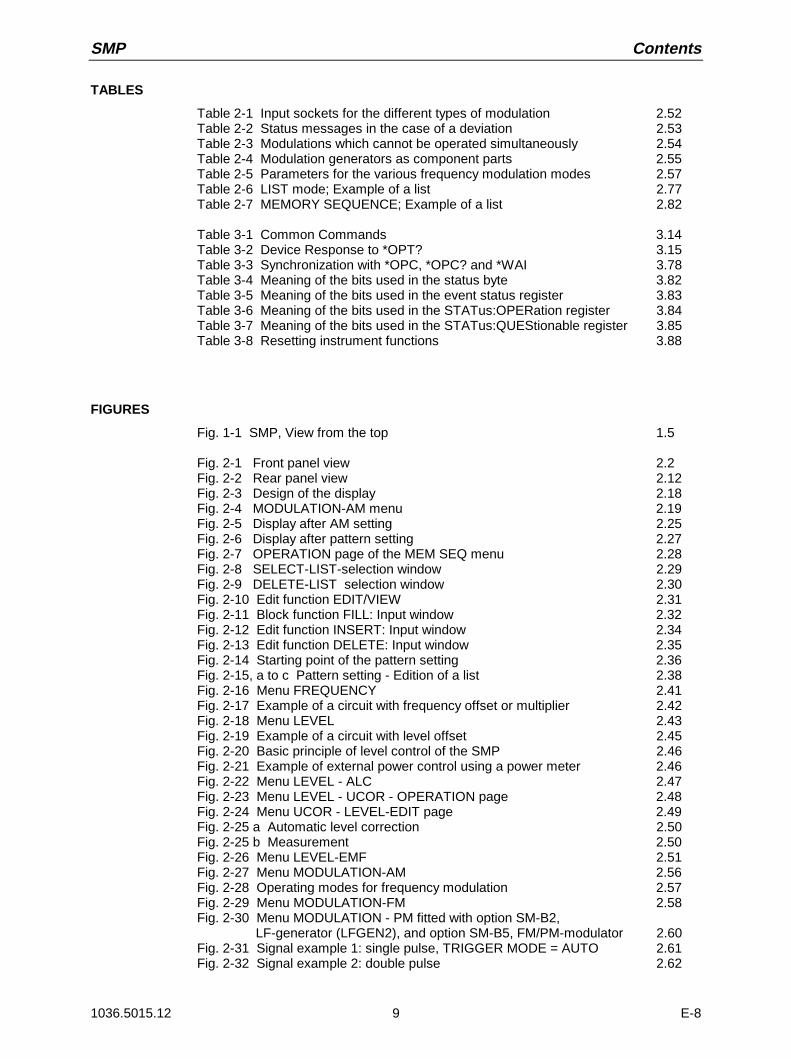
TABLES
Table 2-1 Input sockets for the different types of modulation 2.52Table 2-2 Status messages in the case of a deviation 2.53Table 2-3 Modulations which cannot be operated simultaneously 2.54Table 2-4 Modulation generators as component parts 2.55Table 2-5 Parameters for the various frequency modulation modes 2.57Table 2-6 LIST mode; Example of a list 2.77Table 2-7 MEMORY SEQUENCE; Example of a list 2.82
Table 3-1 Common Commands 3.14Table 3-2 Device Response to *OPT? 3.15Table 3-3 Synchronization with *OPC, *OPC? and *WAI 3.78Table 3-4 Meaning of the bits used in the status byte 3.82Table 3-5 Meaning of the bits used in the event status register 3.83Table 3-6 Meaning of the bits used in the STATus:OPERation register 3.84Table 3-7 Meaning of the bits used in the STATus:QUEStionable register 3.85Table 3-8 Resetting instrument functions 3.88
FIGURES
Fig. 1-1 SMP, View from the top 1.5
Fig. 2-1 Front panel view 2.2Fig. 2-2 Rear panel view 2.12Fig. 2-3 Design of the display 2.18Fig. 2-4 MODULATION-AM menu 2.19Fig. 2-5 Display after AM setting 2.25Fig. 2-6 Display after pattern setting 2.27Fig. 2-7 OPERATION page of the MEM SEQ menu 2.28Fig. 2-8 SELECT-LIST-selection window 2.29Fig. 2-9 DELETE-LIST selection window 2.30Fig. 2-10 Edit function EDIT/VIEW 2.31Fig. 2-11 Block function FILL: Input window 2.32Fig. 2-12 Edit function INSERT: Input window 2.34Fig. 2-13 Edit function DELETE: Input window 2.35Fig. 2-14 Starting point of the pattern setting 2.36Fig. 2-15, a to c Pattern setting - Edition of a list 2.38Fig. 2-16 Menu FREQUENCY 2.41Fig. 2-17 Example of a circuit with frequency offset or multiplier 2.42Fig. 2-18 Menu LEVEL 2.43Fig. 2-19 Example of a circuit with level offset 2.45Fig. 2-20 Basic principle of level control of the SMP 2.46Fig. 2-21 Example of external power control using a power meter 2.46Fig. 2-22 Menu LEVEL - ALC 2.47Fig. 2-23 Menu LEVEL - UCOR - OPERATION page 2.48Fig. 2-24 Menu UCOR - LEVEL-EDIT page 2.49Fig. 2-25 a Automatic level correction 2.50Fig. 2-25 b Measurement 2.50Fig. 2-26 Menu LEVEL-EMF 2.51Fig. 2-27 Menu MODULATION-AM 2.56Fig. 2-28 Operating modes for frequency modulation 2.57Fig. 2-29 Menu MODULATION-FM 2.58Fig. 2-30 Menu MODULATION - PM fitted with option SM-B2, LF-generator (LFGEN2), and option SM-B5, FM/PM-modulator 2.60Fig. 2-31 Signal example 1: single pulse, TRIGGER MODE = AUTO 2.61Fig. 2-32 Signal example 2: double pulse 2.62
Contents SMP
1036.5015.12 10 E-8
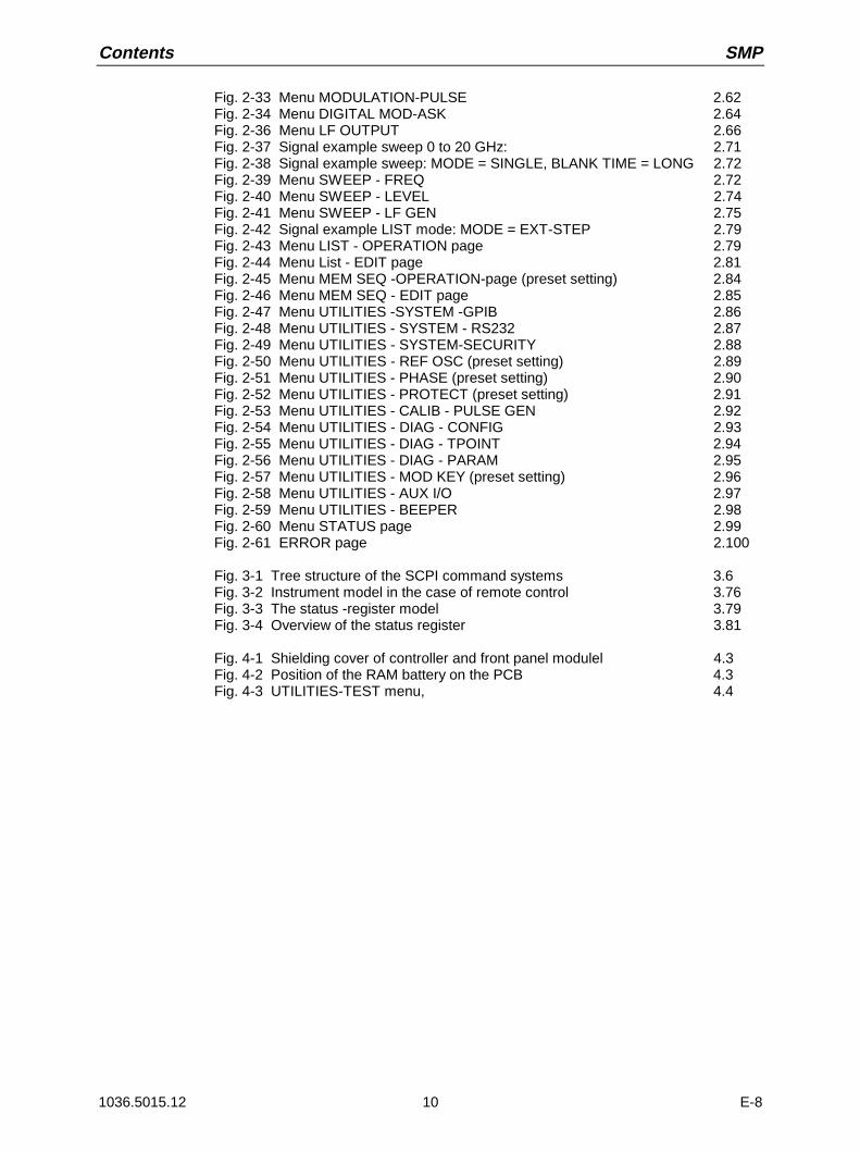
Fig. 2-33 Menu MODULATION-PULSE 2.62Fig. 2-34 Menu DIGITAL MOD-ASK 2.64Fig. 2-36 Menu LF OUTPUT 2.66Fig. 2-37 Signal example sweep 0 to 20 GHz: 2.71Fig. 2-38 Signal example sweep: MODE = SINGLE, BLANK TIME = LONG 2.72Fig. 2-39 Menu SWEEP - FREQ 2.72Fig. 2-40 Menu SWEEP - LEVEL 2.74Fig. 2-41 Menu SWEEP - LF GEN 2.75Fig. 2-42 Signal example LIST mode: MODE = EXT-STEP 2.79Fig. 2-43 Menu LIST - OPERATION page 2.79Fig. 2-44 Menu List - EDIT page 2.81Fig. 2-45 Menu MEM SEQ -OPERATION-page (preset setting) 2.84Fig. 2-46 Menu MEM SEQ - EDIT page 2.85Fig. 2-47 Menu UTILITIES -SYSTEM -GPIB 2.86Fig. 2-48 Menu UTILITIES - SYSTEM - RS232 2.87Fig. 2-49 Menu UTILITIES - SYSTEM-SECURITY 2.88Fig. 2-50 Menu UTILITIES - REF OSC (preset setting) 2.89Fig. 2-51 Menu UTILITIES - PHASE (preset setting) 2.90Fig. 2-52 Menu UTILITIES - PROTECT (preset setting) 2.91Fig. 2-53 Menu UTILITIES - CALIB - PULSE GEN 2.92Fig. 2-54 Menu UTILITIES - DIAG - CONFIG 2.93Fig. 2-55 Menu UTILITIES - DIAG - TPOINT 2.94Fig. 2-56 Menu UTILITIES - DIAG - PARAM 2.95Fig. 2-57 Menu UTILITIES - MOD KEY (preset setting) 2.96Fig. 2-58 Menu UTILITIES - AUX I/O 2.97Fig. 2-59 Menu UTILITIES - BEEPER 2.98Fig. 2-60 Menu STATUS page 2.99Fig. 2-61 ERROR page 2.100
Fig. 3-1 Tree structure of the SCPI command systems 3.6Fig. 3-2 Instrument model in the case of remote control 3.76Fig. 3-3 The status -register model 3.79Fig. 3-4 Overview of the status register 3.81
Fig. 4-1 Shielding cover of controller and front panel modulel 4.3Fig. 4-2 Position of the RAM battery on the PCB 4.3Fig. 4-3 UTILITIES-TEST menu, 4.4

1171.0000.42-02.00 Sheet 1
Before putting the product into operation for the first time, make sure to read the following
S a f e t y I n s t r u c t i o n s
Rohde & Schwarz makes every effort to keep the safety standard of its products up to date and to offer its customers the highest possible degree of safety. Our products and the auxiliary equipment required for them are designed and tested in accordance with the relevant safety standards. Compliance with these standards is continuously monitored by our quality assurance system. This product has been designed and tested in accordance with the EC Certificate of Conformity and has left the manufacturers plant in a condition fully complying with safety standards. To maintain this condition and to ensure safe operation, observe all instructions and warnings provided in this manual. If you have any questions regarding these safety instructions, Rohde & Schwarz will be happy to answer them.
Furthermore, it is your responsibility to use the product in an appropriate manner. This product is designed for use solely in industrial and laboratory environments or in the field and must not be used in any way that may cause personal injury or property damage. You are responsible if the product is used for an intention other than its designated purpose or in disregard of the manufacturer's instructions. The manufacturer shall assume no responsibility for such use of the product.
The product is used for its designated purpose if it is used in accordance with its operating manual and within its performance limits (see data sheet, documentation, the following safety instructions). Using the products requires technical skills and knowledge of English. It is therefore essential that the products be used exclusively by skilled and specialized staff or thoroughly trained personnel with the required skills. If personal safety gear is required for using Rohde & Schwarz products, this will be indicated at the appropriate place in the product documentation.
Symbols and safety labels
Observe operating instructions
Weight indication for units >18 kg
Danger of electric shock
Warning! Hot surface
PE terminal Ground Ground terminal
Attention! Electrostatic sensitive devices
Supply voltage ON/OFF
Standby indication
Direct current (DC)
Alternating current (AC)
Direct/alternating current (DC/AC)
Device fully protected by double/reinforced insulation

Safety Instructions
1171.0000.42-02.00 Sheet 2
Observing the safety instructions will help prevent personal injury or damage of any kind caused by dangerous situations. Therefore, carefully read through and adhere to the following safety instructions before putting the product into operation. It is also absolutely essential to observe the additional safety instructions on personal safety that appear in other parts of the documentation. In these safety instructions, the word "product" refers to all merchandise sold and distributed by Rohde & Schwarz, including instruments, systems and all accessories.
Tags and their meaning DANGER This tag indicates a safety hazard with a high potential of risk for the
user that can result in death or serious injuries. WARNING This tag indicates a safety hazard with a medium potential of risk for the
user that can result in death or serious injuries. CAUTION This tag indicates a safety hazard with a low potential of risk for the user
that can result in slight or minor injuries. ATTENTION This tag indicates the possibility of incorrect use that can cause damage
to the product. NOTE This tag indicates a situation where the user should pay special attention
to operating the product but which does not lead to damage. These tags are in accordance with the standard definition for civil applications in the European Economic Area. Definitions that deviate from the standard definition may also exist. It is therefore essential to make sure that the tags described here are always used only in connection with the associated documentation and the associated product. The use of tags in connection with unassociated products or unassociated documentation can result in misinterpretations and thus contribute to personal injury or material damage.
Basic safety instructions 1. The product may be operated only under
the operating conditions and in the positions specified by the manufacturer. Its ventilation must not be obstructed during operation. Unless otherwise specified, the following requirements apply to Rohde & Schwarz products: prescribed operating position is always with the housing floor facing down, IP protection 2X, pollution severity 2, overvoltage category 2, use only in enclosed spaces, max. operation altitude max. 2000 m. Unless specified otherwise in the data sheet, a tolerance of ±10% shall apply to the nominal voltage and of ±5% to the nominal frequency.
2. Applicable local or national safety regulations and rules for the prevention of accidents must be observed in all work performed. The product may be opened only by authorized, specially trained personnel. Prior to performing any work on the product or opening the product, the
product must be disconnected from the supply network. Any adjustments, replacements of parts, maintenance or repair must be carried out only by technical personnel authorized by Rohde & Schwarz. Only original parts may be used for replacing parts relevant to safety (e.g. power switches, power transformers, fuses). A safety test must always be performed after parts relevant to safety have been replaced (visual inspection, PE conductor test, insulation resistance measurement, leakage current measurement, functional test).
3. As with all industrially manufactured goods, the use of substances that induce an allergic reaction (allergens, e.g. nickel) such as aluminum cannot be generally excluded. If you develop an allergic reaction (such as a skin rash, frequent sneezing, red eyes or respiratory difficulties), consult a physician immediately to determine the cause.

Safety Instructions
1171.0000.42-02.00 Sheet 3
4. If products/components are mechanically and/or thermically processed in a manner that goes beyond their intended use, hazardous substances (heavy-metal dust such as lead, beryllium, nickel) may be released. For this reason, the product may only be disassembled, e.g. for disposal purposes, by specially trained personnel. Improper disassembly may be hazardous to your health. National waste disposal regulations must be observed.
5. If handling the product yields hazardous substances or fuels that must be disposed of in a special way, e.g. coolants or engine oils that must be replenished regularly, the safety instructions of the manufacturer of the hazardous substances or fuels and the applicable regional waste disposal regulations must be observed. Also observe the relevant safety instructions in the product documentation.
6. Depending on the function, certain products such as RF radio equipment can produce an elevated level of electromagnetic radiation. Considering that unborn life requires increased protection, pregnant women should be protected by appropriate measures. Persons with pacemakers may also be endangered by electromagnetic radiation. The employer is required to assess workplaces where there is a special risk of exposure to radiation and, if necessary, take measures to avert the danger.
7. Operating the products requires special training and intense concentration. Make certain that persons who use the products are physically, mentally and emotionally fit enough to handle operating the products; otherwise injuries or material damage may occur. It is the responsibility of the employer to select suitable personnel for operating the products.
8. Prior to switching on the product, it must be ensured that the nominal voltage setting on the product matches the nominal voltage of the AC supply network. If a different voltage is to be set, the power fuse of the product may have to be changed accordingly.
9. In the case of products of safety class I with movable power cord and connector, operation is permitted only on sockets with earthing contact and protective earth connection.
10. Intentionally breaking the protective earth connection either in the feed line or in the product itself is not permitted. Doing so can result in the danger of an electric shock from the product. If extension cords or connector strips are implemented, they must be checked on a regular basis to ensure that they are safe to use.
11. If the product has no power switch for disconnection from the AC supply, the plug of the connecting cable is regarded as the disconnecting device. In such cases, it must be ensured that the power plug is easily reachable and accessible at all times (length of connecting cable approx. 2 m). Functional or electronic switches are not suitable for providing disconnection from the AC supply. If products without power switches are integrated in racks or systems, a disconnecting device must be provided at the system level.
12. Never use the product if the power cable is damaged. By taking appropriate safety measures and carefully laying the power cable, ensure that the cable cannot be damaged and that no one can be hurt by e.g. tripping over the cable or suffering an electric shock.
13. The product may be operated only from TN/TT supply networks fused with max. 16 A.
14. Do not insert the plug into sockets that are dusty or dirty. Insert the plug firmly and all the way into the socket. Otherwise this can result in sparks, fire and/or injuries.
15. Do not overload any sockets, extension cords or connector strips; doing so can cause fire or electric shocks.
16. For measurements in circuits with voltages Vrms > 30 V, suitable measures (e.g. appropriate measuring equipment, fusing, current limiting, electrical separation, insulation) should be taken to avoid any hazards.
17. Ensure that the connections with information technology equipment comply with IEC 950/EN 60950.
18. Never remove the cover or part of the housing while you are operating the product. This will expose circuits and components and can lead to injuries, fire or damage to the product.
Safety Instructions
1171.0000.42-02.00 Sheet 4
19. If a product is to be permanently installed, the connection between the PE terminal on site and the product's PE conductor must be made first before any other connection is made. The product may be installed and connected only by a skilled electrician.
20. For permanently installed equipment without built-in fuses, circuit breakers or similar protective devices, the supply circuit must be fused in such a way that suitable protection is provided for users and products.
21. Do not insert any objects into the openings in the housing that are not designed for this purpose. Never pour any liquids onto or into the housing. This can cause short circuits inside the product and/or electric shocks, fire or injuries.
22. Use suitable overvoltage protection to ensure that no overvoltage (such as that caused by a thunderstorm) can reach the product. Otherwise the operating personnel will be endangered by electric shocks.
23. Rohde & Schwarz products are not protected against penetration of water, unless otherwise specified (see also safety instruction 1.). If this is not taken into account, there exists the danger of electric shock or damage to the product, which can also lead to personal injury.
24. Never use the product under conditions in which condensation has formed or can form in or on the product, e.g. if the product was moved from a cold to a warm environment.
25. Do not close any slots or openings on the product, since they are necessary for ventilation and prevent the product from overheating. Do not place the product on soft surfaces such as sofas or rugs or inside a closed housing, unless this is well ventilated.
26. Do not place the product on heat-generating devices such as radiators or fan heaters. The temperature of the environment must not exceed the maximum temperature specified in the data sheet.
27. Batteries and storage batteries must not be exposed to high temperatures or fire. Keep batteries and storage batteries away from children. If batteries or storage batteries are improperly replaced, this can cause an explosion (warning: lithium cells). Replace the battery or storage battery only with the
matching Rohde & Schwarz type (see spare parts list). Batteries and storage batteries are hazardous waste. Dispose of them only in specially marked containers. Observe local regulations regarding waste disposal. Do not short-circuit batteries or storage batteries.
28. Please be aware that in the event of a fire, toxic substances (gases, liquids etc.) that may be hazardous to your health may escape from the product.
29. Please be aware of the weight of the product. Be careful when moving it; otherwise you may injure your back or other parts of your body.
30. Do not place the product on surfaces, vehicles, cabinets or tables that for reasons of weight or stability are unsuitable for this purpose. Always follow the manufacturer's installation instructions when installing the product and fastening it to objects or structures (e.g. walls and shelves).
31. Handles on the products are designed exclusively for personnel to hold or carry the product. It is therefore not permissible to use handles for fastening the product to or on means of transport such as cranes, fork lifts, wagons, etc. The user is responsible for securely fastening the products to or on the means of transport and for observing the safety regulations of the manufacturer of the means of transport. Noncompliance can result in personal injury or material damage.
32. If you use the product in a vehicle, it is the sole responsibility of the driver to drive the vehicle safely. Adequately secure the product in the vehicle to prevent injuries or other damage in the event of an accident. Never use the product in a moving vehicle if doing so could distract the driver of the vehicle. The driver is always responsible for the safety of the vehicle; the manufacturer assumes no responsibility for accidents or collisions.
33. If a laser product (e.g. a CD/DVD drive) is integrated in a Rohde & Schwarz product, do not use any other settings or functions than those described in the documentation. Otherwise this may be hazardous to your health, since the laser beam can cause irreversible damage to your eyes. Never try to take such products apart, and never look into the laser beam.

1171.0000.42-02.00 página 1
Por favor lea imprescindiblemente antes de la primera puesta en funcionamiento las siguientes informaciones de seguridad
Informaciones de seguridad
Es el principio de Rohde & Schwarz de tener a sus productos siempre al día con los estandards de seguridad y de ofrecer a sus clientes el máximo grado de seguridad. Nuestros productos y todos los equipos adicionales son siempre fabricados y examinados según las normas de seguridad vigentes. Nuestra sección de gestión de la seguridad de calidad controla constantemente que sean cumplidas estas normas. Este producto ha sido fabricado y examinado según el comprobante de conformidad adjunto según las normas de la CE y ha salido de nuestra planta en estado impecable según los estandards técnicos de seguridad. Para poder preservar este estado y garantizar un funcionamiento libre de peligros, deberá el usuario atenerse a todas las informaciones, informaciones de seguridad y notas de alerta. Rohde&Schwarz está siempre a su disposición en caso de que tengan preguntas referentes a estas informaciones de seguridad.
Además queda en la responsabilidad del usuario utilizar el producto en la forma debida. Este producto solamente fue elaborado para ser utilizado en la indústria y el laboratorio o para fines de campo y de ninguna manera deberá ser utilizado de modo que alguna persona/cosa pueda ser dañada. El uso del producto fuera de sus fines definidos o despreciando las informaciones de seguridad del fabricante queda en la responsabilidad del usuario. El fabricante no se hace en ninguna forma responsable de consecuencias a causa del maluso del producto.
Se parte del uso correcto del producto para los fines definidos si el producto es utilizado dentro de las instrucciones del correspondiente manual del uso y dentro del margen de rendimiento definido (ver hoja de datos, documentación, informaciones de seguridad que siguen). El uso de los productos hace necesarios conocimientos profundos y el conocimiento del idioma inglés. Por eso se deberá tener en cuenta de exclusivamente autorizar para el uso de los productos a personas péritas o debidamente minuciosamente instruidas con los conocimientos citados. Si fuera necesaria indumentaria de seguridad para el uso de productos de R&S, encontrará la información debida en la documentación del producto en el capítulo correspondiente.
Símbolos y definiciones de seguridad
Ver manual de instrucciones del uso
Informaciones para maquinaria con uns peso de > 18kg
Peligro de golpe de corriente
¡Advertencia! Superficie caliente
Conexión a conductor protector
Conexión a tierra
Conexión a masa conductora
¡Cuidado! Elementos de construción con peligro de carga electroestática
potencia EN MARCHA/PARADA
Indicación Stand-by
Corriente continua DC
Corriente alterna AC
Corriente continua/alterna DC/AC
El aparato está protegido en su totalidad por un aislamiento de doble refuerzo
Informaciones de seguridad
1171.0000.42-02.00 página 2
Tener en cuenta las informaciones de seguridad sirve para tratar de evitar daños y peligros de toda clase. Es necesario de que se lean las siguientes informaciones de seguridad concienzudamente y se tengan en cuenta debidamente antes de la puesta en funcionamiento del producto. También deberán ser tenidas en cuenta las informaciones para la protección de personas que encontrarán en otro capítulo de esta documentación y que también son obligatorias de seguir. En las informaciones de seguridad actuales hemos juntado todos los objetos vendidos por Rohde&Schwarz bajo la denominación de producto, entre ellos también aparatos, instalaciones así como toda clase de accesorios.
Palabras de señal y su significado PELIGRO Indica un punto de peligro con gran potencial de riesgo para el
ususario.Punto de peligro que puede llevar hasta la muerte o graves heridas.
ADVERTENCIA Indica un punto de peligro con un protencial de riesgo mediano para el usuario. Punto de peligro que puede llevar hasta la muerte o graves heridas .
ATENCIÓN Indica un punto de peligro con un protencial de riesgo pequeño para el usuario. Punto de peligro que puede llevar hasta heridas leves o pequeñas
CUIDADO Indica la posibilidad de utilizar mal el producto y a consecuencia dañarlo.
INFORMACIÓN Indica una situación en la que deberían seguirse las instrucciones en el uso del producto, pero que no consecuentemente deben de llevar a un daño del mismo.
Las palabras de señal corresponden a la definición habitual para aplicaciones civiles en el ámbito de la comunidad económica europea. Pueden existir definiciones diferentes a esta definición. Por eso se debera tener en cuenta que las palabras de señal aquí descritas sean utilizadas siempre solamente en combinación con la correspondiente documentación y solamente en combinación con el producto correspondiente. La utilización de las palabras de señal en combinación con productos o documentaciones que no les correspondan puede llevar a malinterpretaciones y tener por consecuencia daños en personas u objetos.
Informaciones de seguridad elementales 1. El producto solamente debe ser utilizado
según lo indicado por el fabricante referente a la situación y posición de funcionamiento sin que se obstruya la ventilación. Si no se convino de otra manera, es para los productos R&S válido lo que sigue: como posición de funcionamiento se define principialmente la posición con el suelo de la caja para abajo , modo de protección IP 2X, grado de suciedad 2, categoría de sobrecarga eléctrica 2, utilizar solamente en estancias interiores, utilización hasta 2000 m sobre el nivel del mar. A menos que se especifique otra cosa en la hoja de datos, se aplicará una tolerancia de ±10% sobre el voltaje nominal y de ±5% sobre la frecuencia nominal.
2. En todos los trabajos deberán ser tenidas en cuenta las normas locales de seguridad de trabajo y de prevención de accidentes. El producto solamente debe de ser abierto por personal périto autorizado. Antes de efectuar trabajos en el producto o abrirlo deberá este ser desconectado de la corriente. El ajuste, el cambio de partes, la manutención y la reparación deberán ser solamente efectuadas por electricistas autorizados por R&S. Si se reponen partes con importancia para los aspectos de seguridad (por ejemplo el enchufe, los transformadores o los fusibles), solamente podrán ser sustituidos por partes originales. Despues de cada recambio de partes elementales para la seguridad deberá ser efectuado un control de

Informaciones de seguridad
1171.0000.42-02.00 página 3
seguridad (control a primera vista, control de conductor protector, medición de resistencia de aislamiento, medición de medición de la corriente conductora, control de funcionamiento).
3. Como en todo producto de fabricación industrial no puede ser excluido en general de que se produzcan al usarlo elementos que puedan generar alergias, los llamados elementos alergénicos (por ejemplo el níquel). Si se producieran en el trato con productos R&S reacciones alérgicas, como por ejemplo urticaria, estornudos frecuentes, irritación de la conjuntiva o dificultades al respirar, se deberá consultar inmediatamente a un médico para averigurar los motivos de estas reacciones.
4. Si productos / elementos de construcción son tratados fuera del funcionamiento definido de forma mecánica o térmica, pueden generarse elementos peligrosos (polvos de sustancia de metales pesados como por ejemplo plomo, berilio, níquel). La partición elemental del producto, como por ejemplo sucede en el tratamiento de materias residuales, debe de ser efectuada solamente por personal especializado para estos tratamientos. La partición elemental efectuada inadecuadamente puede generar daños para la salud. Se deben tener en cuenta las directivas nacionales referentes al tratamiento de materias residuales.
5. En el caso de que se produjeran agentes de peligro o combustibles en la aplicación del producto que debieran de ser transferidos a un tratamiento de materias residuales, como por ejemplo agentes refrigerantes que deben ser repuestos en periodos definidos, o aceites para motores, deberan ser tenidas en cuenta las prescripciones de seguridad del fabricante de estos agentes de peligro o combustibles y las regulaciones regionales para el tratamiento de materias residuales. Cuiden también de tener en cuenta en caso dado las prescripciones de seguridad especiales en la descripción del producto.
6. Ciertos productos, como por ejemplo las instalaciones de radiación HF, pueden a causa de su función natural, emitir una radiación electromagnética aumentada. En vista a la protección de la vida en desarrollo deberían ser protegidas personas embarazadas debidamente. También las personas con un bypass pueden correr
peligro a causa de la radiación electromagnética. El empresario está comprometido a valorar y señalar areas de trabajo en las que se corra un riesgo de exposición a radiaciones aumentadas de riesgo aumentado para evitar riesgos.
7. La utilización de los productos requiere instrucciones especiales y una alta concentración en el manejo. Debe de ponerse por seguro de que las personas que manejen los productos estén a la altura de los requerimientos necesarios referente a sus aptitudes físicas, psíquicas y emocionales, ya que de otra manera no se pueden excluir lesiones o daños de objetos. El empresario lleva la responsabilidad de seleccionar el personal usuario apto para el manejo de los productos.
8. Antes de la puesta en marcha del producto se deberá tener por seguro de que la tensión preseleccionada en el producto equivalga a la del la red de distribución. Si es necesario cambiar la preselección de la tensión también se deberán en caso dabo cambiar los fusibles correspondientes del prodcuto.
9. Productos de la clase de seguridad I con alimentación móvil y enchufe individual de producto solamente deberán ser conectados para el funcionamiento a tomas de corriente de contacto de seguridad y con conductor protector conectado.
10. Queda prohibida toda clase de interrupción intencionada del conductor protector, tanto en la toma de corriente como en el mismo producto ya que puede tener como consecuencia el peligro de golpe de corriente por el producto. Si se utilizaran cables o enchufes de extensión se deberá poner al seguro, que es controlado su estado técnico de seguridad.
11. Si el producto no está equipado con un interruptor para desconectarlo de la red, se deberá considerar el enchufe del cable de distribución como interruptor. En estos casos deberá asegurar de que el enchufe sea de fácil acceso y nabejo (medida del cable de distribución aproximadamente 2 m). Los interruptores de función o electrónicos no son aptos para el corte de la red eléctrica. Si los productos sin interruptor están integrados en construciones o instalaciones, se deberá instalar el interruptor al nivel de la instalación.

Informaciones de seguridad
1171.0000.42-02.00 página 4
12. No utilice nunca el producto si está dañado el cable eléctrico. Asegure a través de las medidas de protección y de instalación adecuadas de que el cable de eléctrico no pueda ser dañado o de que nadie pueda ser dañado por él, por ejemplo al tropezar o por un golpe de corriente.
13. Solamente está permitido el funcionamiento en redes de distribución TN/TT aseguradas con fusibles de como máximo 16 A.
14. Nunca conecte el enchufe en tomas de corriente sucias o llenas de polvo. Introduzca el enchufe por completo y fuertemente en la toma de corriente. Si no tiene en consideración estas indicaciones se arriesga a que se originen chispas, fuego y/o heridas.
15. No sobrecargue las tomas de corriente, los cables de extensión o los enchufes de extensión ya que esto pudiera causar fuego o golpes de corriente.
16. En las mediciones en circuitos de corriente con una tensión de entrada de Ueff > 30 V se deberá tomar las precauciones debidas para impedir cualquier peligro (por ejemplo medios de medición adecuados, seguros, limitación de tensión, corte protector, aislamiento etc.).
17. En caso de conexión con aparatos de la técnica informática se deberá tener en cuenta que estos cumplan los requisitos de la EC950/EN60950.
18. Nunca abra la tapa o parte de ella si el producto está en funcionamiento. Esto pone a descubierto los cables y componentes eléctricos y puede causar heridas, fuego o daños en el producto.
19. Si un producto es instalado fijamente en un lugar, se deberá primero conectar el conductor protector fijo con el conductor protector del aparato antes de hacer cualquier otra conexión. La instalación y la conexión deberán ser efecutadas por un electricista especializado.
20. En caso de que los productos que son instalados fijamente en un lugar sean sin protector implementado, autointerruptor o similares objetos de protección, deberá la toma de corriente estar protegida de manera que los productos o los usuarios estén suficientemente protegidos.
21. Por favor, no introduzca ningún objeto que no esté destinado a ello en los orificios de la caja del aparato. No vierta nunca ninguna clase de líquidos sobre o en la caja. Esto puede producir corto circuitos en el producto y/o puede causar golpes de corriente, fuego o heridas.
22. Asegúrese con la protección adecuada de que no pueda originarse en el producto una sobrecarga por ejemplo a causa de una tormenta. Si no se verá el personal que lo utilice expuesto al peligro de un golpe de corriente.
23. Los productos R&S no están protegidos contra el agua si no es que exista otra indicación, ver también punto 1. Si no se tiene en cuenta esto se arriesga el peligro de golpe de corriente o de daños en el producto lo cual también puede llevar al peligro de personas.
24. No utilice el producto bajo condiciones en las que pueda producirse y se hayan producido líquidos de condensación en o dentro del producto como por ejemplo cuando se desplaza el producto de un lugar frío a un lugar caliente.
25. Por favor no cierre ninguna ranura u orificio del producto, ya que estas son necesarias para la ventilación e impiden que el producto se caliente demasiado. No pongan el producto encima de materiales blandos como por ejemplo sofás o alfombras o dentro de una caja cerrada, si esta no está suficientemente ventilada.
26. No ponga el producto sobre aparatos que produzcan calor, como por ejemplo radiadores o calentadores. La temperatura ambiental no debe superar la temperatura máxima especificada en la hoja de datos.
Informaciones de seguridad
1171.0000.42-02.00 página 5
27. Baterías y acumuladores no deben de ser expuestos a temperaturas altas o al fuego. Guardar baterías y acumuladores fuera del alcance de los niños. Si las baterías o los acumuladores no son cambiados con la debida atención existirá peligro de explosión (atención celulas de Litio). Cambiar las baterías o los acumuladores solamente por los del tipo R&S correspondiente (ver lista de piezas de recambio). Baterías y acumuladores son deshechos problemáticos. Por favor tirenlos en los recipientes especiales para este fín. Por favor tengan en cuenta las prescripciones nacionales de cada país referente al tratamiento de deshechos. Nunca sometan las baterías o acumuladores a un corto circuito.
28. Tengan en consideración de que en caso de un incendio pueden escaparse gases tóxicos del producto, que pueden causar daños a la salud.
29. Por favor tengan en cuenta que en caso de un incendio pueden desprenderse del producto agentes venenosos (gases, líquidos etc.) que pueden generar daños a la salud.
30. No sitúe el producto encima de superficies, vehículos, estantes o mesas, que por sus características de peso o de estabilidad no sean aptas para él. Siga siempre las instrucciones de instalación del fabricante cuando instale y asegure el producto en objetos o estructuras (por ejemplo paredes y estantes).
31. Las asas instaladas en los productos sirven solamente de ayuda para el manejo que solamente está previsto para personas. Por eso no está permitido utilizar las asas para la sujecion en o sobre medios de transporte como por ejemplo grúas, carretillas elevadoras de horquilla, carros etc. El usuario es responsable de que los productos sean sujetados de forma segura a los medios de transporte y de que las prescripciones de seguridad del fabricante de los medios de transporte sean tenidas en cuenta. En caso de que no se tengan en cuenta pueden causarse daños en personas y objetos.
32. Si llega a utilizar el producto dentro de un vehículo, queda en la responsabilidad absoluta del conductor que conducir el vehículo de manera segura. Asegure el producto dentro del vehículo debidamente para evitar en caso de un accidente las lesiones u otra clase de daños. No utilice nunca el producto dentro de un vehículo en movimiento si esto pudiera distraer al conductor. Siempre queda en la responsabilidad absoluta del conductor la seguridad del vehículo y el fabricante no asumirá ninguna clase de responsabilidad por accidentes o colisiones.
33. Dado el caso de que esté integrado un producto de laser en un producto R&S (por ejemplo CD/DVD-ROM) no utilice otras instalaciones o funciones que las descritas en la documentación. De otra manera pondrá en peligro su salud, ya que el rayo laser puede dañar irreversiblemente sus ojos. Nunca trate de descomponer estos productos. Nunca mire dentro del rayo laser.


DIN EN ISO 9001 : 2000DIN EN 9100 : 2003DIN EN ISO 14001 : 1996
DQS REG. NO 001954 QM/ST UM
Certified Quality System
Sehr geehrter Kunde,Sie haben sich für den Kauf eines Rohde & Schwarz-Produktes entschie-den. Hiermit erhalten Sie ein nach modernsten Fertigungsmethoden hergestelltes Produkt. Es wurde nach den Regeln unseres Management-systems entwickelt, gefertigt und geprüft. Das Rohde & Schwarz Management-system ist zertifiziert nach:
DIN EN ISO 9001:2000DIN EN 9100:2003DIN EN ISO 14001:1996
Dear Customer,you have decided to buy a Rohde & Schwarz product. You are thus as-sured of receiving a product that is manufactured using the most modern methods available. This product was developed, manufactured and tested in compliance with our quality manage-ment system standards. The Rohde & Schwarz quality manage-ment system is certified according to:
DIN EN ISO 9001:2000DIN EN 9100:2003DIN EN ISO 14001:1996
Cher Client,vous avez choisi d‘acheter un produit Rohde & Schwarz. Vous disposez donc d‘un produit fabriqué d‘après les méthodes les plus avancées. Le développement, la fabrication et les tests respectent nos normes de ges-tion qualité. Le système de gestion qualité de Rohde & Schwarz a été homologué conformément aux normes:
DIN EN ISO 9001:2000DIN EN 9100:2003DIN EN ISO 14001:1996
QUALITÄTSZERTIFIKAT CERTIFICATE OF QUALITY CERTIFICAT DE QUALITÉ

1035.5005.02 CE E-3
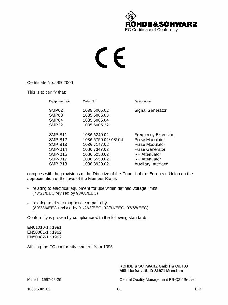
EC Certificate of Conformity
Certificate No.: 9502006
This is to certify that:
Equipment type Order No. Designation
SMP02 1035.5005.02 Signal GeneratorSMP03 1035.5005.03SMP04 1035.5005.04SMP22 1035.5005.22
SMP-B11 1036.6240.02 Frequency ExtensionSMP-B12 1036.5750.02/.03/.04 Pulse ModulatorSMP-B13 1036.7147.02 Pulse ModulatorSMP-B14 1036.7347.02 Pulse GeneratorSMP-B15 1036.5250.02 RF AttenuatorSMP-B17 1036.5550.02 RF AttenuatorSMP-B18 1036.8920.02 Auxiliary Interface
complies with the provisions of the Directive of the Council of the European Union on theapproximation of the laws of the Member States
- relating to electrical equipment for use within defined voltage limits(73/23/EEC revised by 93/68/EEC)
- relating to electromagnetic compatibility(89/336/EEC revised by 91/263/EEC, 92/31/EEC, 93/68/EEC)
Conformity is proven by compliance with the following standards:
EN61010-1 : 1991EN50081-1 : 1992EN50082-1 : 1992
Affixing the EC conformity mark as from 1995
ROHDE & SCHWARZ GmbH & Co. KGMühldorfstr. 15, D-81671 München
Munich, 1997-08-26 Central Quality Management FS-QZ / Becker


1007.8684.14-04.00
Customer Support
Technical support – where and when you need it For quick, expert help with any Rohde & Schwarz equipment, contact one of our Customer Support Centers. A team of highly qualified engineers provides telephone support and will work with you to find a solution to your query on any aspect of the operation, programming or applications of Rohde & Schwarz equipment.
Up-to-date information and upgrades To keep your Rohde & Schwarz equipment always up-to-date, please subscribe to our electronic newsletter at http://www.rohde-schwarz.com/www/response.nsf/newsletterpreselectionor request the desired information and upgrades via email from your Customer Support Center (addresses see below).
Feedback We want to know if we are meeting your support needs. If you have any comments please email us and let us know [email protected].
USA & Canada Monday to Friday (except US public holidays) 8:00 AM – 8:00 PM Eastern Standard Time (EST)
Tel. from USA 888-test-rsa (888-837-8772) (opt 2) From outside USA +1 410 910 7800 (opt 2) Fax +1 410 910 7801
E-mail [email protected]
East Asia Monday to Friday (except Singaporean public holidays) 8:30 AM – 6:00 PM Singapore Time (SGT)
Tel. +65 6 513 0488 Fax +65 6 846 1090
E-mail [email protected]
Rest of the World Monday to Friday (except German public holidays) 08:00 – 17:00 Central European Time (CET)
Tel. from Europe +49 (0) 180 512 42 42 From outside Europe +49 89 4129 13776 Fax +49 (0) 89 41 29 637 78
E-mail [email protected]

SMP Putting into Operation
1035.5005.02 1.1 E-8
1 Preparation for Use
1.1 Putting into Operation
Before putting the SMP into operation, please make sure that
• the covers of the casing are put on and screwed,
• the ventilation openings are free,
• no signal voltage levels exceeding the permissible limits are applied at the inputs,,
• the outputs of the instrument are not overloaded or connected incorrectly.
If these points are not observed, the instrument might be damaged.
1.1.1 Supply Voltage
The SMP can be operated at a.c. systems from 90 to 132 V and 180 to 265 V at system frequenciesfrom 47 to 440 Hz. The power supply socket is situated at the rear of the instrument. The instrumentautomatically sets itself to the voltage applied within the permissible voltage ranges. It is not necessaryto set the instrument to a certain supply voltage.
1.1.2 Power Fuses
The SMP is protected against short circuits by means of two fuses according to nameplate of the powersupply. The fuses are situated in the draw-out fuse holder which is inserted between power supplysocket and power switch (see below).
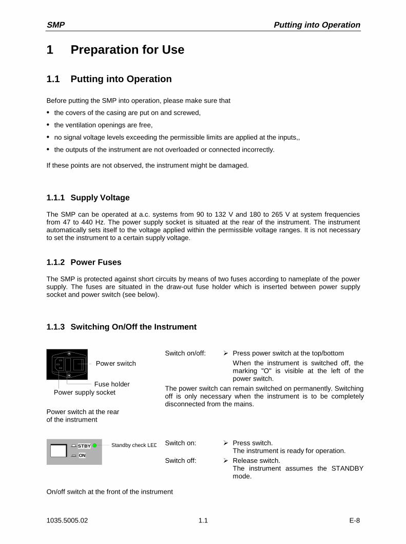
1.1.3 Switching On/Off the Instrument
Power switch
Fuse holderPower supply socket
Switch on/off: À Press power switch at the top/bottom
When the instrument is switched off, themarking "O" is visible at the left of thepower switch.
The power switch can remain switched on permanently. Switchingoff is only necessary when the instrument is to be completelydisconnected from the mains.
Power switch at the rearof the instrument
STBY
ON
Standby check LED Switch on: À Press switch.The instrument is ready for operation.
Switch off: À Release switch.The instrument assumes the STANDBYmode.
On/off switch at the front of the instrument
Putting into Operation SMP
1035.5005.02 1.2 E-8
1.1.4 Initial Status
Upon switching on, the instrument automatically assumes the status which was set when it wasswitched off.If the instrument need not to be operated from the initial status any further, a defined default statusshould be established by pressing the [PRESET] key prior to further settings.
STANDBY Mode
In the STANDBY mode the optional reference oscillator (option SM-B1) remains switched on, whichincreases frequency accuracy.
Frequency accuracy after switching on when the oven-controlled reference oscillator is fitted(option SM-B1)
When switching on from the STANDBY mode, the specified frequency accuracy is reached immediately.If the power switch was switched off, the reference oscillator needs some minutes of warm-up time toreach its nominal frequency. During this period of time, the output frequency does not yet reach its finalvalue either. In the status line in the header field of the display the message "OVEN COLD" is displayedfor this time.
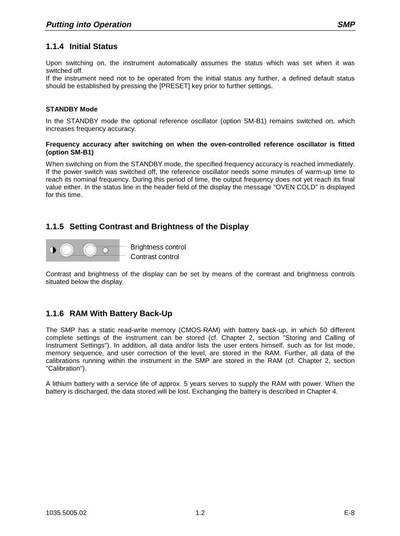
1.1.5 Setting Contrast and Brightness of the Display
Brightness controlContrast control
Contrast and brightness of the display can be set by means of the contrast and brightness controlssituated below the display.
1.1.6 RAM With Battery Back-Up
The SMP has a static read-write memory (CMOS-RAM) with battery back-up, in which 50 differentcomplete settings of the instrument can be stored (cf. Chapter 2, section "Storing and Calling ofInstrument Settings"). In addition, all data and/or lists the user enters himself, such as for list mode,memory sequence, and user correction of the level, are stored in the RAM. Further, all data of thecalibrations running within the instrument in the SMP are stored in the RAM (cf. Chapter 2, section"Calibration").
A lithium battery with a service life of approx. 5 years serves to supply the RAM with power. When thebattery is discharged, the data stored will be lost. Exchanging the battery is described in Chapter 4.
SMP Functional Test
1035.5005.02 1.3 E-8
1.1.7 Preset Setting
A defined setting status is achieved by pressing the [PRESET] key.
Preset Status:
RF frequency 10 GHzRF level -30 dBm
(-20 dBm without option SMP-B15/B17, Attenuator)Reference frequency internal, adjustment offOffsets 0Modulations switched offTransient-free level setting switched off, level attenuator mode: AUTOInternal level control level ALC: ONUser correction level UCOR: OFFPLL bandwidth autoLF output switched offSweep switched offList mode switched offMemory sequence switched offSuppression of indications system security: unalteredProtection of calibration data protection lock: unalteredSettings stored unalteredData, lists etc. stored unalteredIEC-bus address unalteredBeeper unaltered
All parameters and circuit states, even those of operating modes which are not activated, are preset bymeans of Preset.
The presettings going beyond the above list can be seen from the menu representations as of Section2.4 which each indicate the Preset setting status.
1.2 Functional Test
On switching on the instrument and permanently during operation, the SMP carries out a self test. TheROM contents as well as the battery of the non-volatile RAM are checked on switching on theinstrument and the RAM contents with every calling the memory. The most important instrumentfunctions are automatically monitored during operation.
If an error is detected, the message "ERROR" is displayed in the status line. For further identification ofthe error, press the [ERROR] key. Thereupon a description of the error/s is displayed (cf. Chapter 2,section "Error Messages"). Return to the menu exited by pressing the [RETURN] key.
If required, the self tests can be induced purposefully. See section "Functional Test".Further, internal test points can be polled by the user and the results be read out and displayed. Seesection "Voltage Indication of Test Points".

Fitting the Options SMP
1035.5005.02 1.4 E-8
1.3 Fitting the Options
Due to its variety of options, the SMP offers the possibility of providing the instrument with theequipment exactly corresponding to the application. Newly fitted options are automatically recognizedand the relevant parameters added in the menu.
After every change of the instrument configuration, the CMOS RAM has to be cleared as the storagedata shift:
À Switch off the instrument
À Switch the instrument on again with the [RESET] key pressed
The internal calibration routines YFOM, ALC AMP and PULSE GEN now have to be called up again torestore the cleared calibration values.These routines are accessible via menu UTILITIES-CALIB (see Section "Calibration" and servicemanual). The calibration routines have to be carried out in the following order:
1. YFOM
2. ALC AMP
3. PULSE GEN (if installed)
1.3.1 Opening the Casing
Remove paneling À Remove four screws in the two tilt feet at the rear of the instrument.
À Remove the upper paneling towards the top and rear.
À Turn the instrument.
À Remove the lower paneling towards the top and rear.
Open ventilation ducts When an option is fitted at a slot which has not been used up to now,the appropriate ventilation duct of the plexiglas plate at the left in thecasing frame must be opened. The openings are pre-punched so thatthe respective part is easy to break out.
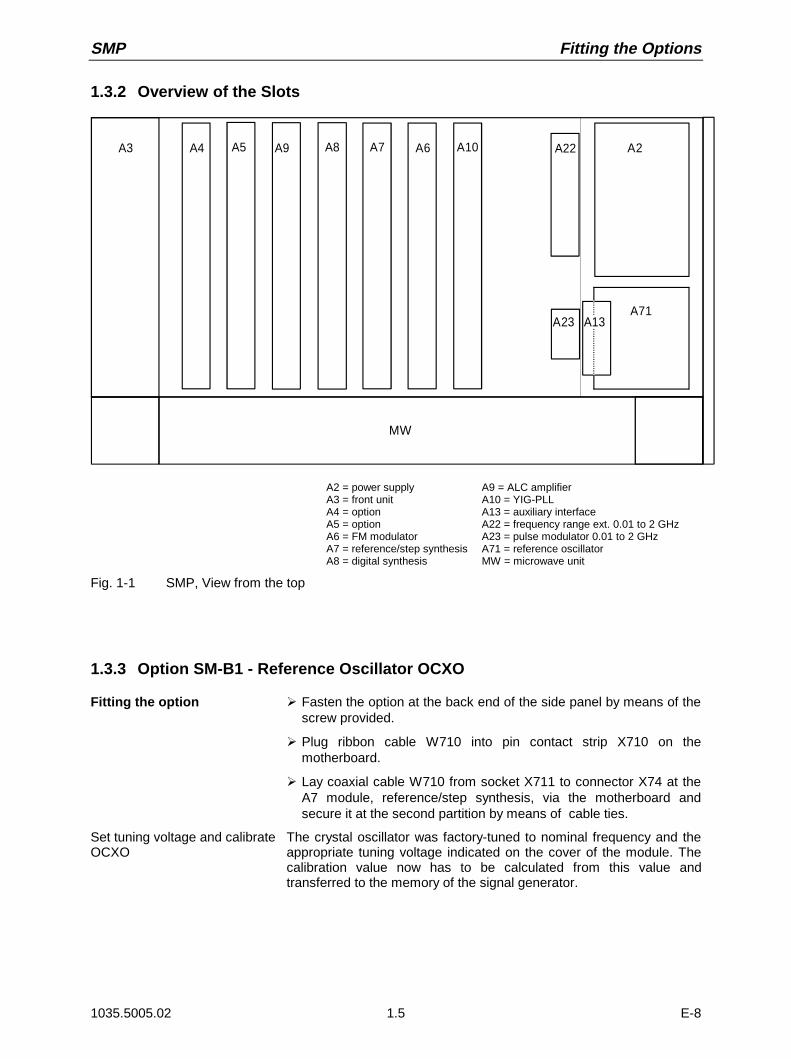
SMP Fitting the Options
1035.5005.02 1.5 E-8
1.3.2 Overview of the Slots
A3 A4 A5 A9 A8 A7 A6 A10
A71
A22 A2
MW
A23 A13
A2 = power supplyA3 = front unitA4 = optionA5 = optionA6 = FM modulatorA7 = reference/step synthesisA8 = digital synthesis
A9 = ALC amplifierA10 = YIG-PLLA13 = auxiliary interfaceA22 = frequency range ext. 0.01 to 2 GHzA23 = pulse modulator 0.01 to 2 GHzA71 = reference oscillatorMW = microwave unit
Fig. 1-1 SMP, View from the top
1.3.3 Option SM-B1 - Reference Oscillator OCXO
Fitting the option À Fasten the option at the back end of the side panel by means of thescrew provided.
À Plug ribbon cable W710 into pin contact strip X710 on themotherboard.
À Lay coaxial cable W710 from socket X711 to connector X74 at theA7 module, reference/step synthesis, via the motherboard andsecure it at the second partition by means of cable ties.
Set tuning voltage and calibrateOCXO
The crystal oscillator was factory-tuned to nominal frequency and theappropriate tuning voltage indicated on the cover of the module. Thecalibration value now has to be calculated from this value andtransferred to the memory of the signal generator.
Fitting the Options SMP
1035.5005.02 1.6 E-8
Calculate calibration value The tuning voltage is generated by a 12b-bit-D/A converter which isscaled such that a tuning voltage of 12 volts is generated withcalibration value (CALIBRATION DATA) 4000.The calibration value is thus calculated from the tuning voltage (Vtun)as follows
CALIBRATION DATA = Vtun × 4000 / 12
For checking purposes, the voltage at pin 16 of plug X710 on themotherboard can be remeasured and corrected if necessary. A checkby means of frequency measurement may only be made after awarm-up of 2 hours and against a calibrated reference.
Store calibration value À Call menu UTILITIES-CALIB-REF OSC.
À Enter the calculated calibration voltage with CALIBRATION DATAby means of the rotary knob or keypad.
À Select STORE CALIBRATION DATA
À Terminate entry using the [SELECT] keyThe new calibration value is stored in the EPROM.
Note: The flash EPROM does not permit the deletion of individualdata. Thus new memory space is occupied for each calibration.If there is no memory space available any more, the EPROMmust be cleared by an authorized service shop and be writteninto anew. Thus a calibration should only be made if necessary
1.3.4 Option SM-B2 - LF Generator
Fitting as 1st generator As 1st generator, the LF generator is fitted at the rear slot A5.
À Withdraw jumper X30/31 on module A9, ALC amplifier.
À Plug jumper X3 at position 2-3 (on the right) on the option (to theright of multipoint connector X50).
Fitting as 2nd generator If there already is a generator at slot A5, the LF generator is mountedat slot A4.
À Withdraw jumper X32/33 on module A9, ALC amplifier..
À Plug jumper X3 at position 1-2 on the option.
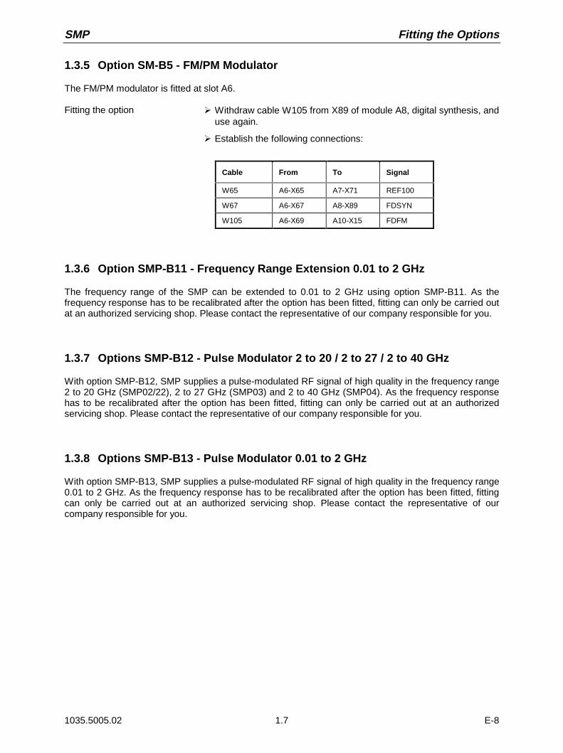
SMP Fitting the Options
1035.5005.02 1.7 E-8
1.3.5 Option SM-B5 - FM/PM Modulator
The FM/PM modulator is fitted at slot A6.
Fitting the option À Withdraw cable W105 from X89 of module A8, digital synthesis, anduse again.
À Establish the following connections:
Cable From To Signal
W65 A6-X65 A7-X71 REF100
W67 A6-X67 A8-X89 FDSYN
W105 A6-X69 A10-X15 FDFM
1.3.6 Option SMP-B11 - Frequency Range Extension 0.01 to 2 GHz
The frequency range of the SMP can be extended to 0.01 to 2 GHz using option SMP-B11. As thefrequency response has to be recalibrated after the option has been fitted, fitting can only be carried outat an authorized servicing shop. Please contact the representative of our company responsible for you.
1.3.7 Options SMP-B12 - Pulse Modulator 2 to 20 / 2 to 27 / 2 to 40 GHz
With option SMP-B12, SMP supplies a pulse-modulated RF signal of high quality in the frequency range2 to 20 GHz (SMP02/22), 2 to 27 GHz (SMP03) and 2 to 40 GHz (SMP04). As the frequency responsehas to be recalibrated after the option has been fitted, fitting can only be carried out at an authorizedservicing shop. Please contact the representative of our company responsible for you.
1.3.8 Options SMP-B13 - Pulse Modulator 0.01 to 2 GHz
With option SMP-B13, SMP supplies a pulse-modulated RF signal of high quality in the frequency range0.01 to 2 GHz. As the frequency response has to be recalibrated after the option has been fitted, fittingcan only be carried out at an authorized servicing shop. Please contact the representative of ourcompany responsible for you.
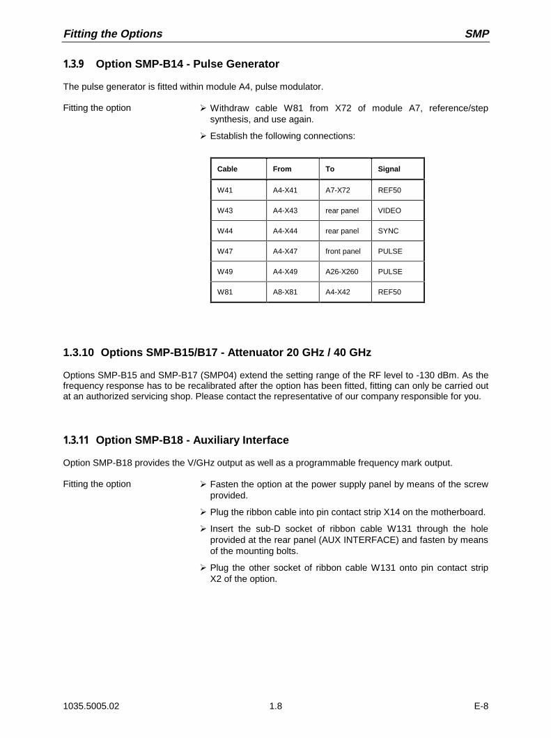
Fitting the Options SMP
1035.5005.02 1.8 E-8
1.3.9 Option SMP-B14 - Pulse Generator
The pulse generator is fitted within module A4, pulse modulator.
Fitting the option À Withdraw cable W81 from X72 of module A7, reference/stepsynthesis, and use again.
À Establish the following connections:
Cable From To Signal
W41 A4-X41 A7-X72 REF50
W43 A4-X43 rear panel VIDEO
W44 A4-X44 rear panel SYNC
W47 A4-X47 front panel PULSE
W49 A4-X49 A26-X260 PULSE
W81 A8-X81 A4-X42 REF50
1.3.10 Options SMP-B15/B17 - Attenuator 20 GHz / 40 GHz
Options SMP-B15 and SMP-B17 (SMP04) extend the setting range of the RF level to -130 dBm. As thefrequency response has to be recalibrated after the option has been fitted, fitting can only be carried outat an authorized servicing shop. Please contact the representative of our company responsible for you.
1.3.11 Option SMP-B18 - Auxiliary Interface
Option SMP-B18 provides the V/GHz output as well as a programmable frequency mark output.
Fitting the option À Fasten the option at the power supply panel by means of the screwprovided.
À Plug the ribbon cable into pin contact strip X14 on the motherboard.
À Insert the sub-D socket of ribbon cable W131 through the holeprovided at the rear panel (AUX INTERFACE) and fasten by meansof the mounting bolts.
À Plug the other socket of ribbon cable W131 onto pin contact stripX2 of the option.
SMP Fitting the Options
1035.5005.02 1.9 E-8
1.3.12 Option SMP-B19 /SMP-B20 - Rear Panel Connections for RF and LF
With options SMP-B19 and SMP-B20, the inputs and outputs can be changed from the front to the rearpanel. The mounting instructions are attached to the option. As the frequency response has to berecalibrated after the option has been fitted, fitting can only be carried out at an authorized servicingshop. Please contact the representative of our company responsible for you.
1.4 Mounting into a 19" Rack
Caution: Ensure free air inlet at the perforation of the side walls and air outlet at the rear of theinstrument in rack mounting.
The SMP can be mounted into a 19" rack by means of rack adapter ZZA-94 (stock no. 396.4905.00).The mounting instructions are attached to the adapter.


SMP Front Panel
1035.5005.02 2.1 E-8
2 Operation
2.1 Explanation of Front and Rear Panel
2.1.1 Elements of the Front Panel
2.1.1.1 Display(cf. Fig. 2-1 Front panel view, display)
1
FREQUENCYLEVEL
MODULATION
DIGITAL MOD
LF OUTPUT
SWEEP
LIST
MEM SEQUTILITIES
HELP
AMFMPM
PULSE
FREQ 10.000 000 000 0 GHz LEVEL - 30.0 dBm
FM1 DEVIATION
FM1 SOURCE
LFGEN1 FREQ
FM2 DEVIATION
FM2 SOURCELFGEN2 FREQ
LFGEN2 SHAPE
EXT1 COUPLING
EXT1 IMPEDANCE
FM
1.00 kHz OFF LFGEN1 EXT1 EXT2
0.4k 1k 3k 15k Hz
2.00 kHz
OFF LFGEN2 EXT1 EXT2 27.500 0 kHz
SIN SQR TRI NOI
AC DC
600 100k Ω
MODE UNLOCKED LOCKED PRECISE
The display shows in the
header field: - the current frequency and levelsettings.
- status messages.
- error messages.
menu field: - the main menu and the submenusselected with the current settings.
Parameters can be selected and changed in themenus indicated.
See as wellSection"Display"
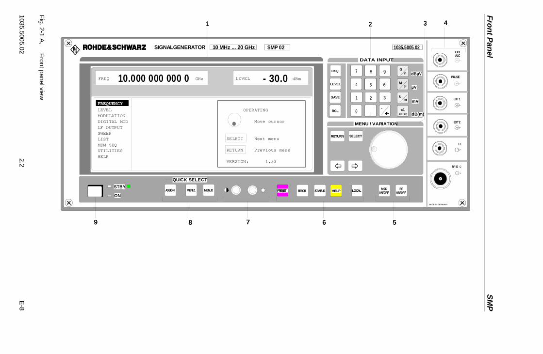
Fro
nt P
anel
SM
P
1035.5005.022.2
E-8
EXT 2
RF 50 Ω
SIGNALGENERATOR 10 MHz ... 20 GHz SMP 02 1035.5005.02
EXT 1
PULSE
ALC
8 97
5 64
2 31
.-
0
Ï
FREQ
LEVEL
SAVE
RCL
Gn
M
k
x1
µ
m
ENTER
dBµV
µV
mV
dB(m)
DATA INPUT
RF0N/0FFLOCAL M0D
0N/0FFHELPSTATUSERRORPRESETSTBY
ONASSIGN MENU1 MENU2
QUICK SELECT
OPERATING
Move cursor
SELECT Next menu
RETURN Previous menu VERSION: 1.33
FREQUENCY
LEVELMODULATIONDIGITAL MODLF OUTPUTSWEEPLISTMEM SEQUTILITIESHELP
FREQ 10.000 000 000 0 GHz LEVEL - 30.0 dBm
LF
MENU / VARIATION
SELECT
× Ø
56789
4321
MADE IN GERMANY
RETURN
EXT
Fig. 2-1 A
, F
ront panel view

SMP Front Panel
1035.5005.02 2.3 E-8
2.1.1.2 Controls(cf. Fig. 2-1 A and B, front panel view, controls)
2 DATA INPUT
Parameter field
FREQ
LEVEL
SAVE
RCL
Parameters RF frequency and RF level can be entereddirectly by means of the parameter keys, alternativelyto menu operation. Further, complete instrumentsettings can be stored and called.
FREQ Opens the setting of the RF frequency viavalue input or variation by means of a rotaryknob. The current menu is maintained.Return to the menu by means of the[RETURN] key. (Setting of the RF frequencyalso in the FREQUENCY menu).
LEVEL Opens the setting of the RF level via valueinput or variation by means of a rotary knob.The current menu is maintained. Return tothe menu by means of the [RETURN] key.(Setting of the RF level also in the LEVELmenu).
SAVE Opens the storing of the current instrumentsetting. Memory selection is effected byentering a number (1 to 50) and is finished bymeans of the [ENTER] key.
RCL Opens the calling of an instrument settingstored. Memory selection is effected byentering a number (1 to 50) and is finished bymeans of the [ENTER] key.
See as wellSection"Use of [FREQ] and[LEVEL] Keys"
Section"RF Frequency"
Section"RF Level"
Section"Storing and Calling ofInstrument Settings"
Numeric input field
8 97
5 64
2 31
.-0Ï
Numeric values, decimal point and minus sign can beentered by means of the digital keys.
0 to 9 Enters the digit.
ì Enters the decimal point
-/← Enters the minus sign.Deletes the last input (digit, sign or decimalpoint) - key [BACKSPACE].
See as wellSection"Basic OperatingSteps"

Fro
nt P
anel
SM
P
1035.5005.022.4
E-8
EXT 2
RF 50 Ω
SIGNALGENERATOR 10 MHz ... 20 GHz SMP 02 1035.5005.02
EXT 1
PULSE
ALC
8 97
5 64
2 31
.-
0
Ï
FREQ
LEVEL
SAVE
RCL
Gn
M
k
x1
µ
m
ENTER
dBµV
µV
mV
dB(m)
DATA INPUT
RF0N/0FFLOCAL M0D
0N/0FFHELPSTATUSERRORPRESETSTBY
ONASSIGN MENU1 MENU2
QUICK SELECT
OPERATING
Move cursor
SELECT Next menu
RETURN Previous menu VERSION: 1.33
FREQUENCY
LEVELMODULATIONDIGITAL MOD
LF OUTPUTSWEEPLISTMEM SEQUTILITIESHELP
FREQ 10.000 000 000 0 GHz LEVEL - 30.0 dBm
LF
MENU / VARIATION
SELECT
× Ø
56789
4321
MADE IN GERMANY
RETURN
EXT
Fig.2-1 B
,F
ront panel view
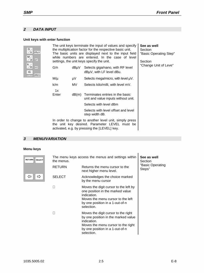
SMP Front Panel
1035.5005.02 2.5 E-8
2 DATA INPUT
Unit keys with enter function
Gn
M
k
x1
µ
m
ENTER
dBµV
µV
mV
dB(m)
The unit keys terminate the input of values and specifythe multiplication factor for the respective basic unit.The basic units are displayed next to the input fieldwhile numbers are entered. In the case of levelsettings, the unit keys specify the unit.
G/n dBµV Selects giga/nano, with RF leveldBµV, with LF level dBu.
M/µ µV Selects mega/micro, with level µV.
k/m MV Selects kilo/milli, with level mV.
1xEnter dB(m) Terminates entries in the basic
unit and value inputs without unit.
Selects with level dBm
Selects with level offset and levelstep width dB.
In order to change to another level unit, simply pressthe unit key desired. Parameter LEVEL must beactivated, e.g. by pressing the [LEVEL] key.
See as wellSection"Basic Operating Step"
Section"Change Unit of Leve"
3 MENU/VARIATION
Menu keys
SELECTRETURN
× Ø
The menu keys access the menus and settings withinthe menus.
RETURN Returns the menu cursor to thenext higher menu level.
SELECT Acknowledges the choice markedby the menu cursor
⇐ Moves the digit cursor to the left byone position in the marked valueindication.Moves the menu cursor to the leftby one position in a 1-out-of-nselection.
⇒ Moves the digit cursor to the rightby one position in the marked valueindication.Moves the menu cursor to the rightby one position in a 1-out-of-nselection.
See as wellSection"Basic OperatingSteps"

Fro
nt P
anel
SM
P
1035.5005.022.6
E-8
EXT 2
RF 50 Ω
SIGNALGENERATOR 10 MHz ... 20 GHz SMP 02 1035.5005.02
EXT 1
PULSE
ALC
8 97
5 64
2 31
.-
0
Ï
FREQ
LEVEL
SAVE
RCL
Gn
M
k
x1
µ
m
ENTER
dBµV
µV
mV
dB(m)
DATA INPUT
RF0N/0FFLOCAL M0D
0N/0FFHELPSTATUSERRORPRESETSTBY
ONASSIGN MENU1 MENU2
QUICK SELECT
OPERATING
Move cursor
SELECT Next menu
RETURN Previous menu VERSION: 1.33
FREQUENCY
LEVELMODULATIONDIGITAL MOD
LF OUTPUTSWEEPLISTMEM SEQUTILITIESHELP
FREQ 10.000 000 000 0 GHz LEVEL - 30.0 dBm
LF
MENU / VARIATION
SELECT
× Ø
56789
4321
MADE IN GERMANY
RETURN
EXT
Fig.2-1 B
,F
ront panel view
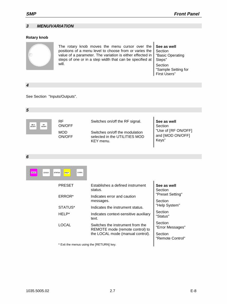
SMP Front Panel
1035.5005.02 2.7 E-8
3 MENU/VARIATION
Rotary knob
The rotary knob moves the menu cursor over thepositions of a menu level to choose from or varies thevalue of a parameter. The variation is either effected insteps of one or in a step width that can be specified atwill.
See as wellSection"Basic OperatingSteps"
Section"Sample Setting forFirst Users"
4
See Section "Inputs/Outputs".
5
RF0N/0FF
M0 D0N/0F F
RF Switches on/off the RF signal.ON/OFF
MOD Switches on/off the modulationON/OFF selected in the UTILITIES MOD
KEY menu.
See as wellSection"Use of [RF ON/OFF]and [MOD ON/OFF]Keys"
6
LOCALHELPSTATUSERRORPRESET
PRESET Establishes a defined instrumentstatus.
ERROR* Indicates error and cautionmessages.
STATUS* Indicates the instrument status.
HELP* Indicates context-sensitive auxiliarytext.
LOCAL Switches the instrument from theREMOTE mode (remote control) tothe LOCAL mode (manual control).
* Exit the menus using the [RETURN] key.
See as wellSection"Preset Setting"
Section"Help System"
Section"Status"
Section"Error Messages"
Section"Remote Control"

Fro
nt P
anel
SM
P
1035.5005.022.8
E-8
EXT 2
RF 50 Ω
SIGNALGENERATOR 10 MHz ... 20 GHz SMP 02 1035.5005.02
EXT 1
PULSE
ALC
8 97
5 64
2 31
.-0
Ï
FREQ
LEVEL
SAVE
RCL
Gn
M
k
x1
µ
m
ENTER
dBµV
µV
mV
dB(m)
DATA INPUT
RF0N/0FF
LOCAL M0D0N/0FFHELPSTATUSERRORPRESET
STBY
ONASSIGN MENU1 MENU2
QUICK SELECT
OPERATING
Move cursor
SELECT Next menu
RETURN Previous menu VERSION: 1.33
FREQUENCY
LEVELMODULATIONDIGITAL MODLF OUTPUTSWEEPLISTMEM SEQUTILITIESHELP
FREQ 10.000 000 000 0 GHz LEVEL - 30.0 dBm
LF
MENU / VARIATION
SELECT
× Ø
56789
4321
MADE IN GERMANY
RETURN
EXT
Fig.2-1
B,
Front panel view

SMP Front Panel
1035.5005.02 2.9 E-8
7
Brightness and contrast of the display can be set usingthe rotary knobs.
Contrast
Brightness
See as wellSection"Setting of Contrast andBrightness of theDisplay"
8 QUICK SELECT
ASSGIN MENU 1 MENU 2
QUICK SELECT
The menu-quick-selection keys permit fast access totwo menus selected.
ASSIGN Stores the current menu as menu1when the MENU1 key is pressedafterwards or as menu2 when theMENU2 key is pressed afterwards.
MENU1 Activates menu1 stored.
MENU2 Activates menu2 stored.
See as wellSection"Basic Operating Steps"
9 Switching On/Off
STBY
ON
The On/Off switch switches the instrument from thestandby mode to the ready-for-operation status.Prerequisite: The power switch at the rear of theinstrument must be switched on.
STBY LED is illuminated in the standbymode.
See as well
Section"Switching On/Off theInstrument"
Section"Elements of the Rear Panel, Power Switch"

Fro
nt P
anel
SM
P
1035.5005.022.10
E-8
EXT 2
RF 50 Ω
SIGNALGENERATOR 10 MHz ... 20 GHz SMP 02 1035.5005.02
EXT 1
PULSE
ALC
8 97
5 64
2 31
.-
0
Ï
FREQ
LEVEL
SAVE
RCL
Gn
M
k
x1
µ
m
ENTER
dBµV
µV
mV
dB(m)
DATA INPUT
RF0N/0FFLOCAL M0D
0N/0FFHELPSTATUSERRORPRESETSTBY
ONASSIGN MENU1 MENU2
QUICK SELECT
OPERATING
Move cursor
SELECT Next menu
RETURN Previous menu VERSION: 1.33
FREQUENCY
LEVELMODULATIONDIGITAL MODLF OUTPUTSWEEPLISTMEM SEQUTILITIESHELP
FREQ 10.000 000 000 0 GHz LEVEL - 30.0 dBm
LF
MENU / VARIATION
SELECT
× Ø
56789
4321
MADE IN GERMANY
RETURN
EXT
Fig.2-1 C
,F
ront panel view
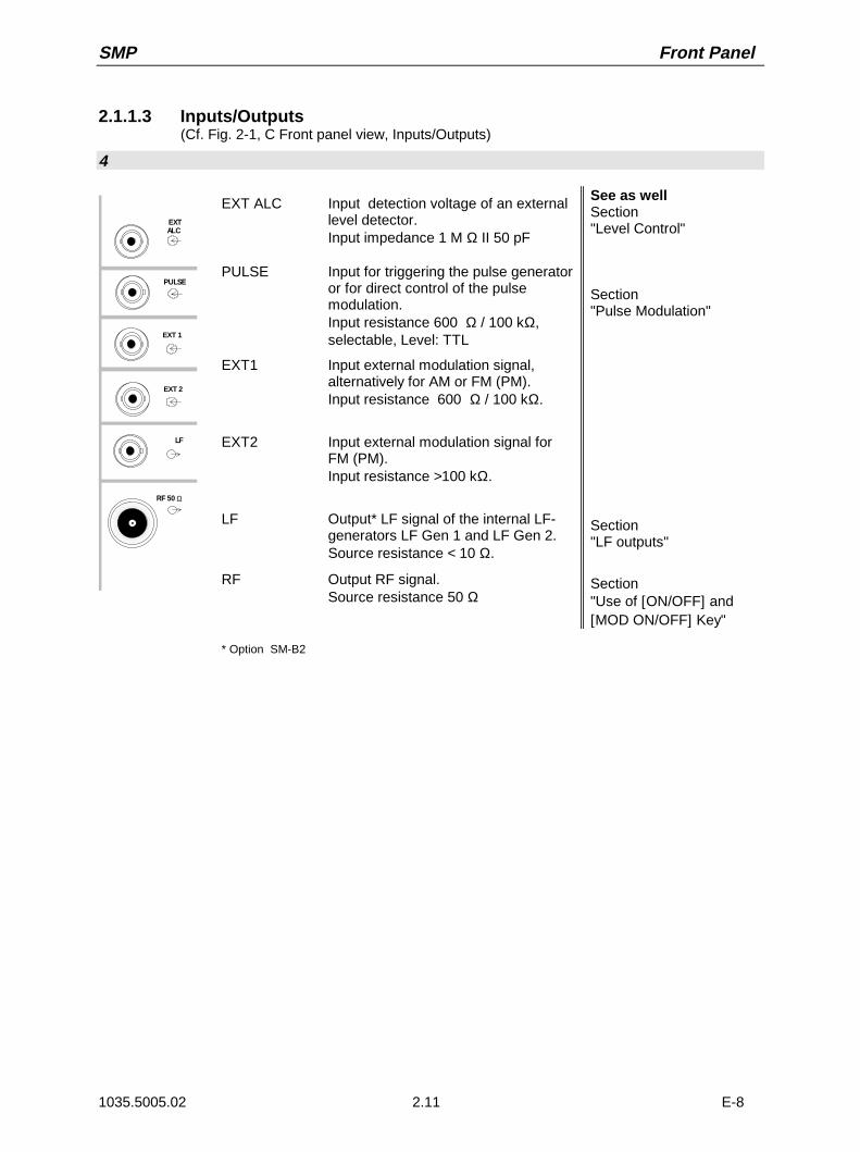
SMP Front Panel
1035.5005.02 2.11 E-8
2.1.1.3 Inputs/Outputs(Cf. Fig. 2-1, C Front panel view, Inputs/Outputs)
4
EXT 2
RF 50 Ω
EXT 1
PULSE
ALC
LF
EXT
EXT ALC Input detection voltage of an externallevel detector.Input impedance 1 M Ω II 50 pF
PULSE Input for triggering the pulse generatoror for direct control of the pulsemodulation.Input resistance 600 Ω / 100 kΩ,selectable, Level: TTL
EXT1 Input external modulation signal,alternatively for AM or FM (PM).Input resistance 600 Ω / 100 kΩ.
EXT2 Input external modulation signal forFM (PM).Input resistance >100 kΩ.
LF Output* LF signal of the internal LF-generators LF Gen 1 and LF Gen 2.Source resistance < 10 Ω.
RF Output RF signal.Source resistance 50 Ω
See as wellSection"Level Control"
Section"Pulse Modulation"
Section"LF outputs"
Section"Use of [ON/OFF] and[MOD ON/OFF] Key"
* Option SM-B2
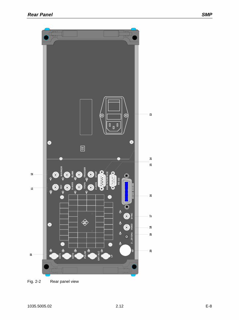
Rear Panel SMP
1035.5005.02 2.12 E-8
IEC
625
IEE
E48
8R
F2
...2
0 G
Hz
VID
EO
1112
10
MA
RK
ER
BLA
NK
Z-A
XIS
ST
OP
RE
F
X-A
XIS
V/G
Hz
TR
IGG
ER
SY
NC
EX
T A
LC
EX
T1
EX
T2
PU
LS
E
LF
AU
X I
NT
ER
FA
CE
2019
1817
1615
1413
RS
232
Fig. 2-2 Rear panel view

SMP Rear Panel
1035.5005.02 2.13 E-8
2.1.2 Elements of the Rear Panel(Cf. Fig. 2-2, Rear panel view)
10
PULSE
PULSE
PULSE
PULSE
EXT1
EXT2
EXT ALC
LF
Cut-outs, provided to relocate the inputs/outputs at thefront to rear of the rear of the instrument. See as well
Section"Inputs/Outputs"
11
REF
X-AXIS
V/GHz
Z-AXIS
REF Output of the internal 10-MHz-referencesignal with reference internal.Source resistance 50 Ω.Input for external reference frequency withreference external. Selectable in steps of 1MHz to external reference frequenciesfrom 1 MHz to 16 MHz.Input resistance 200 Ω.
X-AXIS Output voltage ramp 0 to 10 V in theSweep operating mode.
V/GHz Output of frequency-proportional voltage.Selectable from 0.5 V/GHz to 1 V/GHz.Source resistance 680 Ω (up to 20 GHz).
Z-AXIS not used
See as wellSection"Reference Frequencyint / ext"
Section"Sweep Outputs"
Section"Sweep Outputs"
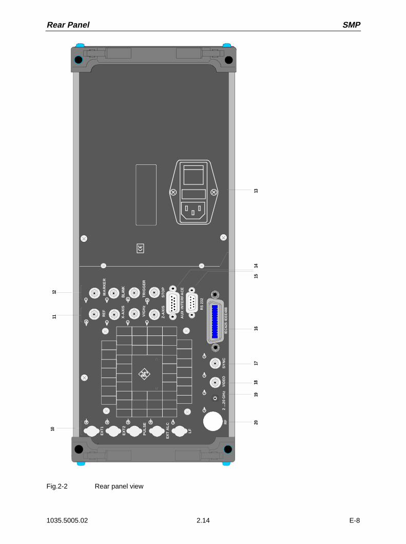
Rear Panel SMP
1035.5005.02 2.14 E-8
IEC
625
IEE
E48
8R
F2
...2
0 G
Hz
VID
EO
1112
10
MA
RK
ER
BLA
NK
Z-A
XIS
ST
OP
RE
F
X-A
XIS
V/G
Hz
TR
IGG
ER
SY
NC
EX
T A
LC
EX
T1
EX
T2
PU
LS
E
LF
AU
X I
NT
ER
FA
CE
2019
1817
1615
1413
RS
232
Fig.2-2 Rear panel view
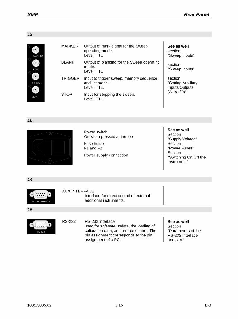
SMP Rear Panel
1035.5005.02 2.15 E-8
12
MARKER
BLANK
TRIGGER
STOP
MARKER Output of mark signal for the Sweepoperating mode.Level: TTL
BLANK Output of blanking for the Sweep operatingmode.Level: TTL
TRIGGER Input to trigger sweep, memory sequenceand list mode.Level: TTL.
STOP Input for stopping the sweep.Level: TTL
See as wellsection"Sweep Inputs"
section"Sweep Inputs"
section"Setting AuxiliaryInputs/Outputs(AUX I/O)"
16
Power switchOn when pressed at the top
Fuse holderF1 and F2
Power supply connection
See as wellSection"Supply Voltage"Section"Power Fuses"Section"Switching On/Off theInstrument"
14
AUX INTERFAC E
AUX INTERFACEInterface for direct control of externaladditional instruments.
15
RS 2 32
RS-232 RS-232 interfaceused for software update, the loading ofcalibration data, and remote control. Thepin assignment corresponds to the pinassignment of a PC.
See as wellSection"Parameters of theRS-232 Interfaceannex A"

Rear Panel SMP
1035.5005.02 2.16 E-8
IEC
625
IEE
E48
8R
F2
...2
0 G
Hz
VID
EO
1112
10
MA
RK
ER
BLA
NK
Z-A
XIS
ST
OP
RE
F
X-A
XIS
V/G
Hz
TR
IGG
ER
SY
NC
EX
T A
LC
EX
T1
EX
T2
PU
LS
E
LF
AU
X I
NT
ER
FA
CE
2019
1817
1615
1413
RS
232
Fig.2-2 Rear panel view

SMP Rear Panel
1035.5005.02 2.17 E-8
16
IEC625 IEEE488
IEC 625 IEC-Bus (IEEE 488)
IEEE 488 Remote-control interface
See as wellSection"Remote Control"
17
SYNC
SYNC Output SYNC signal with pulse modulation.Level: TTL
See as wellSection"Pulse Generator"
18
VIDEO
VIDEO Output video signal with pulse modulation.The signal is synchronous with the RFpulse.Level: TTL
See as wellSection"Pulse Generator"
19
2 ... 20 GHz
2 to 20 GHz Check output. The signal has the samefrequency as the RF signal at the RFfrequencies of 2 to 20 GHz.For frequencies below 2 GHz it is6 GHz higher than the RF signal.For frequencies above 20 GHz (SMP03/04)it is half of the RF signal.Source impedance: 50 Ω
20
RF
RF Cut-out, provided to relocate the RF outputat the front to the rear of the instrument.

Display SMP
1035.5005.02 2.18 E-8
2.2 Operating Concept
2.2.1 Display
Menu cursorDigit cursorSelect mark
FREQUENCYLEVELMODULATIONDIGITAL MODLF OUTPUTSWEEPLISTMEM SEQUTILITIESHELP
AMFMPMPULSE
FREQ 10.000 000 000 0 GHz LEVEL - 30.0 dBm
FM
1
2
3
Main menu Submenu Setting menu
1 Header field2 Status line3 Menu fields
UNLOCKED LOCKED PRECISE
10.0 kHz OFF LFGEN1 EXT1 EXT2 0.4k 1k 3k 15k Hz 10.0 kHz OFF LFGEN2 EXT1 EXT2 1.000 0 kHz SIN SQR TRI NOI
AC DC
600k 100k Ω AC DC
600k 100k Ω
MODE
FM1 DEVIATION
FM1 SOURCE LFGEN1 FREQ
FM2 DEVIATIONFM2 SOURCELFGEN2 FREQLFGEN2 SHAPE
EXT1 COUPLINGEXT1 IMPEDANCEEXT2 COUPLINGEXT2 IMPEDANCE
Fig. 2-3 Design of the display
Header field (1)The header field of the display indicates frequency and level of the RF output signal. Inthe RF-sweep operating mode, the start and stop frequencies are displayed in twolines one above the other. The start and stop levels are indicated in the LEVEL-sweepoperating mode correspondingly.
Status line (2) The status line below describes operating mode and operating state of the instrument.Error messages and notes for caution are also displayed in the status line.
Menu fields (3)The indication fields below the header field are reserved for the menu representations.The image contents of these fields change as a function of the menu selected. Thefield at the left-hand display margin is occupied with the main menu, the topmost levelof the menu structure. The main menu is always faded in.
Each further field adjacent at the right contains submenus.The field ending with the right-hand display margin shows the setting menu. In thismenu all setting values and setting states connected with the menu selected areindicated. When accessing submenus, the higher-order menus remain in the display.The current menu path is evident through the select marks.
Menu cursor The menu cursor shows the user at which position in the menu he is.The position of the menu cursor is evident from the inverse notation ofthe term (white characters on a black background)
Digit cursor As an underscore, the digit cursor marks the position which can bevaried by means of the rotary knob in a value indication.
Select mark The frame around a term marks current menus or valid settings in thesetting menu.
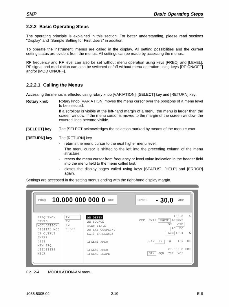
SMP Basic Operating Steps
1035.5005.02 2.19 E-8
2.2.2 Basic Operating Steps
The operating principle is explained in this section. For better understanding, please read sections"Display" and "Sample Setting for First Users" in addition.
To operate the instrument, menus are called in the display. All setting possibilities and the currentsetting status are evident from the menus. All settings can be made by accessing the menus.
RF frequency and RF level can also be set without menu operation using keys [FREQ] and [LEVEL].RF signal and modulation can also be switched on/off without menu operation using keys [RF ON/OFF]and/or [MOD ON/OFF].
2.2.2.1 Calling the Menus
Accessing the menus is effected using rotary knob [VARIATION], [SELECT] key and [RETURN] key.
Rotary knob Rotary knob [VARIATION] moves the menu cursor over the positions of a menu levelto be selected.
If a scrollbar is visible at the left-hand margin of a menu, the menu is larger than thescreen window. If the menu cursor is moved to the margin of the screen window, thecovered lines become visible.
[SELECT] key The [SELECT acknowledges the selection marked by means of the menu cursor.
[RETURN] key The [RETURN] key
- returns the menu cursor to the next higher menu level.
The menu cursor is shifted to the left into the preceding column of the menustructure.
- resets the menu cursor from frequency or level value indication in the header fieldinto the menu field to the menu called last.
- closes the display pages called using keys [STATUS], [HELP] and [ERROR]again.
Settings are accessed in the setting menus ending with the right-hand display margin.
FREQUENCYLEVELMODULATIONDIGITAL MODLF OUTPUTSWEEPLISTMEM SEQUTILITIESHELP
AMFMPMPULSE
AM DEPTHAM SOURCESCAN STATEAM EXT COUPLINGEXT1 IMPEDANCE
LFGEN1 FREQ
LFGEN2 FREQLFGEN2 SHAPE
FREQ 10.000 000 000 0 GHz LEVEL - 30.0 dBm
100.0 %OFF EXT1 LFGEN1 LFGEN2 ON OFF AC DC
600 100k Ω
0.4k 1k 3k 15k Hz
27.500 0 kHz SIN SQR TRI NOI
Fig. 2-4 MODULATION-AM menu

Basic Operating Steps SMP
1035.5005.02 2.20 E-8
2.2.2.2 Selection and Change of Parameters
Select parameter À Set the menu cursor to the name of the parameter desired using the rotaryknob, e.g. to AM DEPTH in the AM menu, Fig. 2.4..
Change settingvalue
À Select parameters.
À Press the [SELECT] key.
À The menu cursor changes from the parameter selected in the left-handcolumn of the setting menu to the setting value on the right, e.g. from AMDEPTH to 100%, Fig. 2-4.
via value inputs À Press the first digit of the new value or minus sign.The old value is deleted, the entry is indicated in the marked field.
À Enter further digits.
À Terminate the input using a unit key or, in the case of inputs in the base unitor in the case of inputs without unit, using the [1x/Enter] key.
À Press the [RETURN] key.The menu cursor wraps back to the appropriate parameter.
using rotary knob À Set the underscore to the position of the setting value to be varied usingkeys [Ø] [×].
À Turn the rotary knob.
The position underscored is varied in steps of 1.
Note: RF frequency and RF level can also be varied in a step width whichcan be defined arbitrarily using the rotary knob. In the respectivesetting menu (FREQUENCY or LEVEL) the step width is entered asKNOB STEP USER and the KNOB STEP set from DECIMAL toUSER. To point to the fact that the step width has been converted tothe value programmed, the underscore as a symbol of the digitcursor disappears in the respective value indication.
1-out-of-n selection À Select parameters.
À Press the [SELECT] key.The menu cursor changes from the parameter selected in the left-handcolumn of the setting menu to the current selection on the right, e.g. fromLFGEN1 FREQ to 0.4 kHz, Fig. 2-4.
À Set the menu cursor to the position desired within the 1-out-of-n selectionusing the rotary knob or cursor keys [⇐] [⇒].
À Press the [SELECT] key.The setting is made.The selection mark which has marked the setting valid up to now wraps tothe new position.
À Press the [RETURN] key.The menu cursor wraps back to the respective parameter

SMP Basic Operating Steps
1035.5005.02 2.21 E-8
Quick selection ofa parameter
The quick selection of a parameter reduces the number of operating steps ifseveral parameters are set successively. The menu cursor can directly be setfurther from line to line in the column of the setting values.
À Press the [SELECT] key.
The menu cursor wraps from the setting value of a parameter to the settingvalue of the parameter in the next line.
The following is true:
- The wrap from a 1-out-of-n selection line into the next line is effectedwhen menu cursor and selection mark are superimposed.
- Actions which can be carried out are skipped.
- If necessary, scrolling is triggered at window limits.
- A wraparound is effected at the end of the menu.
- The column of the setting values can be exited at each position bypressing the [RETURN] key.
2.2.2.3 Triggering Action
Lines in the setting menu which are marked with the " " symbol at the end of the line qualify an actionwhich can be carried out. Instruction SEARCH ONCE in the LEVEL-ALC menu, e.g., switches onlevel control for level calibration for a short period of time.
Trigger action À Set the menu cursor to the respective instruction.
À Press the [SELECT] key.
The action is triggered.
While the action is carried out, the instruction remains framed by theselection mark.
2.2.2.4 Quick Selection of Menu (QUICK SELECT)
The keys of the QUICK SELECT control field are used to call selected menus quickly by one keystroke.
Store menus À Establish the desired operating status of the current menu.
À Press the [ASSIGN] key.
À Press key [MENU1] or [MENU2].
The current menu is stored as menu1 or menu2. That is to say, 2 menuscan be stored in total.
Call menus À Press key [MENU1] or [MENU2].
Menu1 or menu2 stored is displayed. Exactly the operating status which wascurrent at the point of time of storing is reconstructed.

Basic Operating Steps SMP
1035.5005.02 2.22 E-8
2.2.2.5 Use of [FREQ] and [LEVEL] Keys
RF frequency and RF level can be set without menu operation as well using direct keys [FREQ] and[LEVEL].
Key [FREQ]/ [LEVEL] À Press the [FREQ] or [LEVEL] key.
The frequency and/or the level indication in the header field of the displayis marked.
The current menu at the display is maintained.
À Alter the value via a value input or the rotary knob.
À Press the [RETURN] key.
The menu cursor wraps to the position marked last in the menu.
2.2.2.6 Use of [RF ON / OFF] and [MOD ON / OFF] Keys
RF signal and modulation can be switched on/off without menu operation as well using direct keys[RF ON / OFF] and/or [MOD ON / OFF] (see Section [MOD ON/OFF] key as well).
Key [RF ON / OFF] À Press the [RF ON / OFF] key.
The RF output signal is switched on/off.
IEC-bus short command: :OUTP:STAT ON
Key [MOD ON / OFF] À Press the [MOD ON / OFF] key.
The modulation is switched on/off.
A direct IEC-bus command is not available. The modulations have to beswitched on and off in the respective modulation submenus.
2.2.2.7 Changing Unit of Level
For the level, the unit of the value set can be changed without a new value input.
Change level unit À Activate LEVEL parameter.
- Press the [LEVEL] key or
- set the menu cursor in the LEVEL menu to the setting value of theAMPLITUDE parameter.
À Press the unit key with the desired level unit.
The level is indicated in the desired unit.

SMP Sample Setting for First Users
1035.5005.02 2.23 E-8
2.2.2.8 Correction of Input
Digital entries can be corrected by one of the unit/Enter keys before terminating the input.
Key [-/Ï] The backspace key deletes the value entered digit by digit. When the lastdigit is deleted, the previous value is displayed.
Key [RETURN] Pressing the [RETURN] key deletes the entire entry and results in theprevious value being indicated again.
For a subsequent new input in the setting menu, the menu cursor is to be setto the setting value again using the [SELECT] key.
For a subsequent new input via the [FREQ] or [LEVEL] keys, the respectivekey has to be pressed again.
Key [FREQ]/ [LEVEL] In the case of a frequency or level input by means of the [FREQ] or [LEVEL]keys, pressing the [FREQ] and/or [LEVEL] key again deletes the entire input.
2.2.3 Sample Setting for First Users
First users most quickly become familiar with the operation of the instrument if they execute the patternsetting of this section.
First frequency and level of the RF output signal are set via keys [FREQ] and [LEVEL] in the DATAINPUT field:
- Frequency 2,5 GHz- Level 10 dBm
Operating steps Explanations
PRESETReset the instrument to the definedstate.
. 52FREQ Gn
DATA INPUT Set the frequency to 2,5 GHz. Themenu cursor marks the permanentfrequency indication.
01LEVEL
DATA INPUT
x1ENTER
Set the level to 10 dBm. The menucursor marks the permanent levelindication.
RETURNReset the menu cursor to the menufield.

Sample Setting for First Users SMP
1035.5005.02 2.24 E-8
The output signal is to be amplitude-modulated next.
- AM modulation depth 15.5 %- AM signal 3-kHz sine
Operating steps Explanations
.MODULATION
.
MENU / VARIATION
SELECT
MENU / VARIATION Select MODULATION menu.
À Set menu cursor to MODULATIONusing the rotary knob andsubsequently press[SELECT] key.
The submenu is displayed
.AM
.
MENU / VARIATION
SELECT
MENU / VARIATION Select AM submenu
The AM setting menu is displayed.
.AM DEPTH
.
MENU / VARIATION
SELECT
MENU / VARIATION Select AM DEPTH parameter.
The menu cursor marks the settingvalue.
1
DA TA INPUT
x1ENTER5 5.
Enter modulation depth 15.5 % andacknowledge.
RETURNReset menu cursor to AM DEPTH.
.AM SOURCE
.
MENU / VARIATION
SELECT
MENU / VARIATION Select AM SOURCE.
The menu cursor marks the current1-out-of-n selection.

SMP List Editor
1035.5005.02 2.25 D-8
Operating steps Explanations
SELECT.
LFGEN1.
MENU / VARIATIONMENU / VARIATION Select LF generator 1 as modulationsource.
The selection mark marks LFGEN1.AM is faded in the status line as ahint that AM is switched on.
RETURNReset menu cursor to AM SOURCEINT.
.LFGEN1 FREQ
.
MENU / VARIATION Select parameter LFGEN1 FREQ.
The menu cursor marks the currentfrequency selection.
SELECT. 3k .
MENU / VARIATIONMENU / VARIATION Set the frequency of LF generator 1to 3 kHz.
The selection mark marks 3 kHz.
The indications on the display arerepresented in Fig. 2-5.
The AM modulation setting is completed.
FREQUENCY
LEVEL
MODULATION
DIGITAL MOD
LF OUTPUT
SWEEP
LISTMEM SEQ
UTILITIES
HELP
AMFM
PMPULSE
AM DEPTH
AM SOURCE INT
AM SOURCE EXTAM EXT COUPLING
AM POLARITY
LFGEN1 FREQ
LFGEN2 FREQ
LFGEN2 SHAPE
FREQ 250. 000 000 0 MHz LEVEL - 10.0 dBm
AM
15.5 %
OFF LFGEN1 LFGEN2
OFF EXT1 AC DC
NORM INV
0.4k 1k 3k 15k Hz
1.000 0 kHz
SIN SQR TRI NOI
Fig. 2-5 Display after AM setting
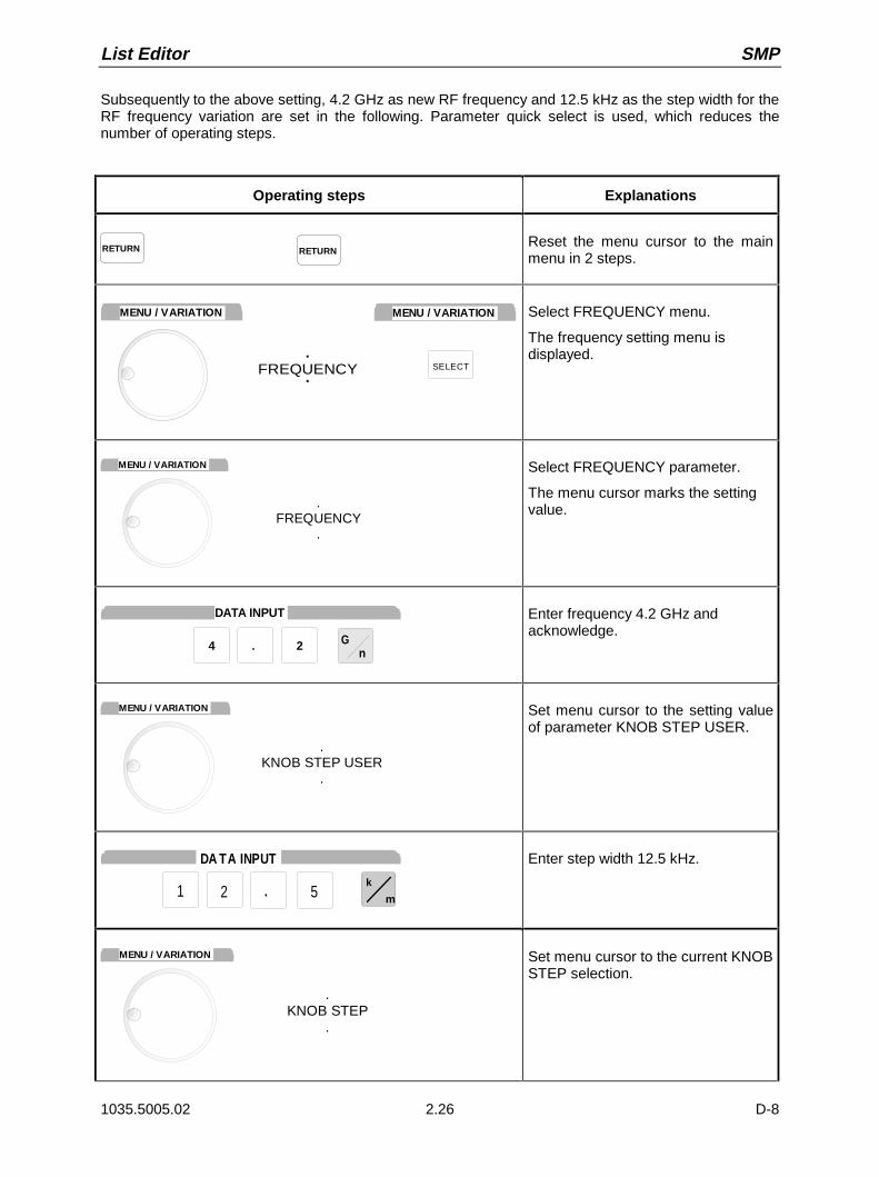
List Editor SMP
1035.5005.02 2.26 D-8
Subsequently to the above setting, 4.2 GHz as new RF frequency and 12.5 kHz as the step width for theRF frequency variation are set in the following. Parameter quick select is used, which reduces thenumber of operating steps.
Operating steps Explanations
RETURN RETURNReset the menu cursor to the mainmenu in 2 steps.
.FREQUENCY.
MENU / VARIATION
SELECT
MENU / VARIATION Select FREQUENCY menu.
The frequency setting menu isdisplayed.
.FREQUENCY
.
MENU / VARIATION Select FREQUENCY parameter.
The menu cursor marks the settingvalue.
. 24 Gn
DATA INPUT Enter frequency 4.2 GHz andacknowledge.
.KNOB STEP USER
.
MENU / VARIATION Set menu cursor to the setting valueof parameter KNOB STEP USER.
1
DA TA INPUT
2 .k
m5
Enter step width 12.5 kHz.
.KNOB STEP
.
MENU / VARIATION Set menu cursor to the current KNOBSTEP selection.

SMP List Editor
1035.5005.02 2.27 D-8
Operating steps Explanations
. USER .
MENU / VARIATION
SELECT
MENU / VARIATION Select USER (user-defined stepwidth).
The selection mark marks USER.
This results in step width 12.5 kHzbeing used in the case of variationusing the rotary knob.
RETURN RETURNReset the menu cursor to the mainmenu in 2 steps.
FREQUENCY
LEVEL
MODULATION
DIGITAL MOD
LF OUTPUT
SWEEP
LISTMEM SEQ
UTILITIES
HELP
FREQUENCYOFFSET
MULTIPLIER 1
KNOB STEP USERKNOB STEPEXCLUDE FROM RCL
FREQ 4.200 000 000 0 GHz LEVEL 10.0 dBm
AM
4.200 000 000.0 MHz
0.0 Hz
12.500 0 kHz
DECIMAL UUSERSER
ON OFF
Fig. 2-6 Display after pattern setting
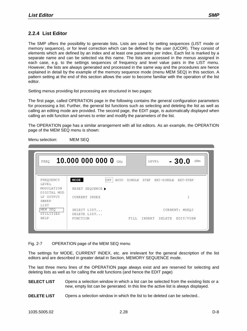
List Editor SMP
1035.5005.02 2.28 D-8
2.2.4 List Editor
The SMP offers the possibility to generate lists. Lists are used for setting sequences (LIST mode ormemory sequence), or for level correction which can be defined by the user (UCOR). They consist ofelements which are defined by an index and at least one parameter per index. Each list is marked by aseparate name and can be selected via this name. The lists are accessed in the menus assigned ineach case, e.g. to the settings sequences of frequency and level value pairs in the LIST menu.However, the lists are always generated and processed in the same way and the procedures are henceexplained in detail by the example of the memory sequence mode (menu MEM SEQ) in this section. Apattern setting at the end of this section allows the user to become familiar with the operation of the listeditor.
Setting menus providing list processing are structured in two pages:
The first page, called OPERATION page in the following contains the general configuration parametersfor processing a list. Further, the general list functions such as selecting and deleting the list as well ascalling an editing mode are provided. The second page, the EDIT page, is automatically displayed whencalling an edit function and serves to enter and modify the parameters of the list.
The OPERATION page has a similar arrangement with all list editors. As an example, the OPERATIONpage of the MEM SEQ menu is shown:
Menu selection: MEM SEQ
FREQUENCYLEVELMODULATIONDIGITAL MODLF OUTPUTSWEEPLISTMEM SEQUTILITIESHELP
LEVEL - 30.0 10.000 000 000 0 dBm
MODE OFF AUTO SINGLE STEP EXT-SINGLE EXT-STEP
RESET SEQUENCE
CURRENT INDEX 1
SELECT LIST... CURRENT: MSEQ2DELETE LIST...FUNCTION FILL INSERT DELETE EDIT/VIEW
FREQ GHz
Fig. 2-7 OPERATION page of the MEM SEQ menu
The settings for MODE, CURRENT INDEX, etc. are irrelevant for the general description of the listeditors and are described in greater detail in Section, MEMORY SEQUENCE mode.
The last three menu lines of the OPERATION page always exist and are reserved for selecting anddeleting lists as well as for calling the edit functions (and hence the EDIT page)
SELECT LIST Opens a selection window in which a list can be selected from the existing lists or anew, empty list can be generated. In this line the active list is always displayed.
DELETE LIST Opens a selection window in which the list to be deleted can be selected..
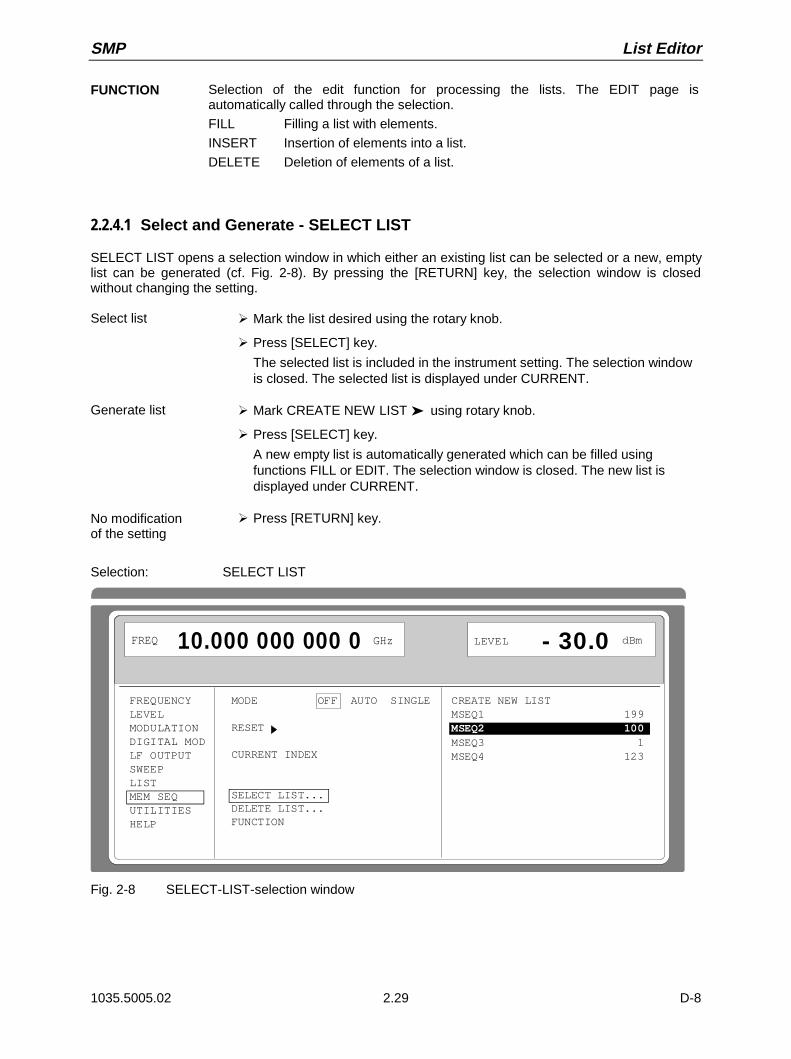
SMP List Editor
1035.5005.02 2.29 D-8
FUNCTION Selection of the edit function for processing the lists. The EDIT page isautomatically called through the selection.
FILL Filling a list with elements.
INSERT Insertion of elements into a list.
DELETE Deletion of elements of a list.
2.2.4.1 Select and Generate - SELECT LIST
SELECT LIST opens a selection window in which either an existing list can be selected or a new, emptylist can be generated (cf. Fig. 2-8). By pressing the [RETURN] key, the selection window is closedwithout changing the setting.
Select list À Mark the list desired using the rotary knob.
À Press [SELECT] key.
The selected list is included in the instrument setting. The selection windowis closed. The selected list is displayed under CURRENT.
Generate list À Mark CREATE NEW LIST using rotary knob.
À Press [SELECT] key.
A new empty list is automatically generated which can be filled usingfunctions FILL or EDIT. The selection window is closed. The new list isdisplayed under CURRENT.
No modificationof the setting
À Press [RETURN] key.
Selection: SELECT LIST
FREQUENCYLEVELMODULATIONDIGITAL MODLF OUTPUTSWEEPLISTMEM SEQUTILITIESHELP
LEVEL - 30.0 10.000 000 000 0 dBm
MODE OFF AUTO SINGLE
RESET
CURRENT INDEX
SELECT LIST... DELETE LIST...FUNCTION
CREATE NEW LISTMSEQ1 199MSEQ2 100MSEQ3 1MSEQ4 123
FREQ GHz
Fig. 2-8 SELECT-LIST-selection window

List Editor SMP
1035.5005.02 2.30 D-8
CREATE NEW LIST Generating a new list. The name of the list cannot be selected freely in thecase of manual control. A definite list name is automatically generated in thefollowing form:
MSEQ<n>, with <n> ∈ 0 to 9, e.g. MSEQ1 (with Memory Sequence)
This applies correspondingly to the other operating modes. In the case ofLIST mode, LIST1 would be generated for example. If a list is created via IECbus, an arbitrary list name can be given. Unrestricted access is also possibleby means of the selection window.
MSEQ2 100 The list currently set is marked in the selection window by means of theselection mark, here MSEQ2. In addition to the list name, the length of the listis given, here 100 elements.
2.2.4.2 Deletion of Lists - DELETE LIST
DELETE LIST opens a selection window in which the list to be deleted can be selected.. The lists arerepresented together with their name and their length (cf. Fig. 2-9). By pressing the [RETURN] key theselection window is exited without deleting a list.
Delete list À Mark desired list using the rotary knob.
À Press [SELECT] key.
The prompt "enter [SELECT to delete list/sequence?" is displayed
ÀPress [SELECT] key.
The list is deleted. If the prompt is acknowledged with the [RETURN] key,however, the list is not deleted. The selection window is automaticallyclosed due to the acknowledgment of the prompt.
Selection: DELETE LIST
FREQUENCYLEVELMODULATIONDIGITAL MODLF OUTPUTSWEEPLISTMEM SEQUTILITIESHELP
LEVEL - 30.0 10.000 000 000 0 dBm
MODE OFF AUTO SINGLE
RESET SEQUENCE
CURRENT INDEX
SELECT LIST... DELETE LIST...FUNCTION
MSEQ1 199MSEQ2 100MSEQ3 1MSEQ4 123
FREQ GHz
Fig. 2-9 DELETE-LIST selection window
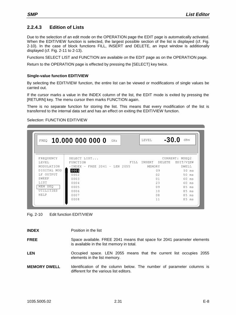
SMP List Editor
1035.5005.02 2.31 E-8
2.2.4.3 Edition of Lists
Due to the selection of an edit mode on the OPERATION page the EDIT page is automatically activated.When the EDIT/VIEW function is selected, the largest possible section of the list is displayed (cf. Fig.2-10). In the case of block functions FILL, INSERT and DELETE, an input window is additionallydisplayed (cf. Fig. 2-11 to 2-13).
Functions SELECT LIST and FUNCTION are available on the EDIT page as on the OPERATION page.
Return to the OPERATION page is effected by pressing the [SELECT] key twice.
Single-value function EDIT/VIEW
By selecting the EDIT/VIEW function, the entire list can be viewed or modifications of single values becarried out.
If the cursor marks a value in the INDEX column of the list, the EDIT mode is exited by pressing the[RETURN] key. The menu cursor then marks FUNCTION again.
There is no separate function for storing the list. This means that every modification of the list istransferred to the internal data set and has an effect on exiting the EDIT/VIEW function.
Selection: FUNCTION EDIT/VIEW
FREQUENCYLEVELMODULATIONDIGITAL MODLF OUTPUTSWEEPLISTMEM SEQUTILITIESHELP
DELETE
FREQ 10.000 000 000 0 GHz LEVEL -30.0 dBm
INSERTFILL EDIT/VIEWSELECT LIST... CURRENT: MSEQ2FUNCTION-INDEX - FREE 2041 - LEN 2055 MEMORY DWELL 0001 09 50 ms 0002 02 50 ms 0003 01 60 ms 0004 23 60 ms 0005 09 85 ms 0006 10 85 ms 0007 08 85 ms 0008 11 85 ms
Fig. 2-10 Edit function EDIT/VIEW
INDEX Position in the list
FREE Space available. FREE 2041 means that space for 2041 parameter elementsis available in the list memory in total.
LEN Occupied space. LEN 2055 means that the current list occupies 2055elements in the list memory.
MEMORY DWELL Identification of the column below. The number of parameter columns isdifferent for the various list editors.
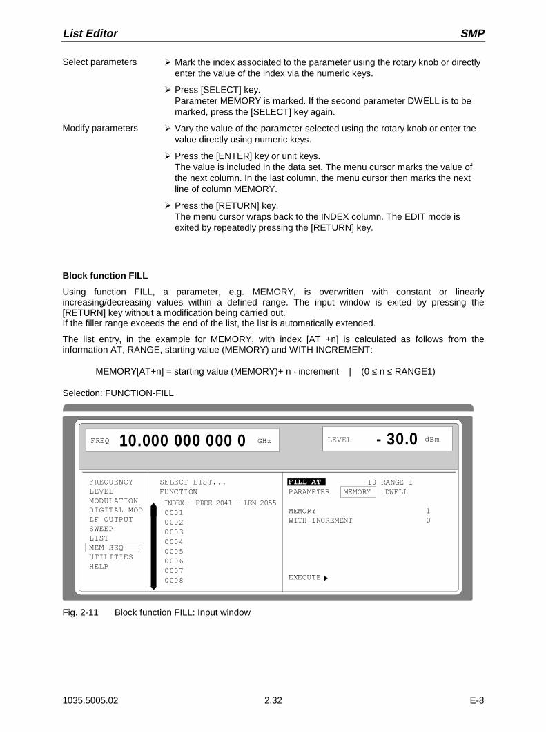
List Editor SMP
1035.5005.02 2.32 E-8
Select parameters À Mark the index associated to the parameter using the rotary knob or directlyenter the value of the index via the numeric keys.
À Press [SELECT] key.Parameter MEMORY is marked. If the second parameter DWELL is to bemarked, press the [SELECT] key again.
Modify parameters À Vary the value of the parameter selected using the rotary knob or enter thevalue directly using numeric keys.
À Press the [ENTER] key or unit keys.The value is included in the data set. The menu cursor marks the value ofthe next column. In the last column, the menu cursor then marks the nextline of column MEMORY.
À Press the [RETURN] key.The menu cursor wraps back to the INDEX column. The EDIT mode isexited by repeatedly pressing the [RETURN] key.
Block function FILL
Using function FILL, a parameter, e.g. MEMORY, is overwritten with constant or linearlyincreasing/decreasing values within a defined range. The input window is exited by pressing the[RETURN] key without a modification being carried out.If the filler range exceeds the end of the list, the list is automatically extended.
The list entry, in the example for MEMORY, with index [AT +n] is calculated as follows from theinformation AT, RANGE, starting value (MEMORY) and WITH INCREMENT:
MEMORY[AT+n] = starting value (MEMORY)+ n · increment | (0 ≤ n ≤ RANGE1)
Selection: FUNCTION-FILL
FREQUENCYLEVELMODULATIONDIGITAL MODLF OUTPUTSWEEPLISTMEM SEQUTILITIESHELP
FREQ 10.000 000 000 0 GHz LEVEL - 30.0 dBm
SELECT LIST...FUNCTION
-INDEX - FREE 2041 - LEN 2055 0001 0002 0003 0004 0005 0006 0007 0008
FILL AT 10 RANGE 1PARAMETER MEMORY DWELL
MEMORY 1WITH INCREMENT 0
EXECUTE
Fig. 2-11 Block function FILL: Input window
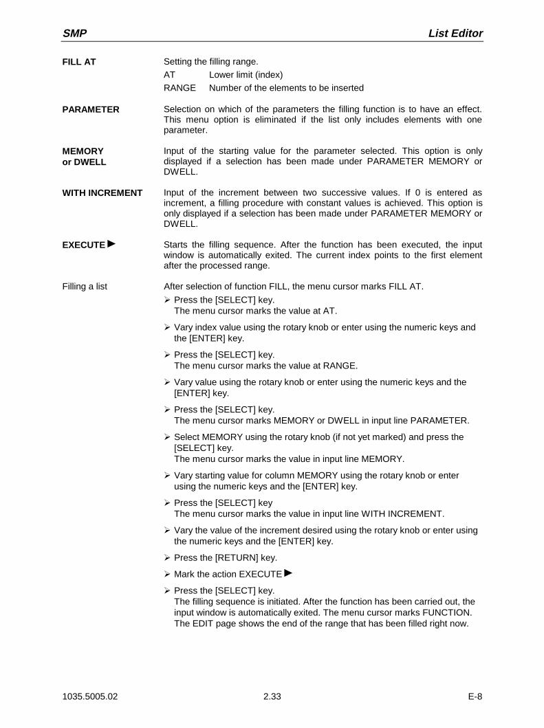
SMP List Editor
1035.5005.02 2.33 E-8
FILL AT Setting the filling range.
AT Lower limit (index)
RANGE Number of the elements to be inserted
PARAMETER Selection on which of the parameters the filling function is to have an effect.This menu option is eliminated if the list only includes elements with oneparameter.
MEMORYor DWELL
Input of the starting value for the parameter selected. This option is onlydisplayed if a selection has been made under PARAMETER MEMORY orDWELL.
WITH INCREMENT Input of the increment between two successive values. If 0 is entered asincrement, a filling procedure with constant values is achieved. This option isonly displayed if a selection has been made under PARAMETER MEMORY orDWELL.
EXECUTE Starts the filling sequence. After the function has been executed, the inputwindow is automatically exited. The current index points to the first elementafter the processed range.
Filling a list After selection of function FILL, the menu cursor marks FILL AT.
À Press the [SELECT] key.The menu cursor marks the value at AT.
À Vary index value using the rotary knob or enter using the numeric keys andthe [ENTER] key.
À Press the [SELECT] key.The menu cursor marks the value at RANGE.
À Vary value using the rotary knob or enter using the numeric keys and the[ENTER] key.
À Press the [SELECT] key.The menu cursor marks MEMORY or DWELL in input line PARAMETER.
À Select MEMORY using the rotary knob (if not yet marked) and press the[SELECT] key.The menu cursor marks the value in input line MEMORY.
À Vary starting value for column MEMORY using the rotary knob or enterusing the numeric keys and the [ENTER] key.
À Press the [SELECT] keyThe menu cursor marks the value in input line WITH INCREMENT.
À Vary the value of the increment desired using the rotary knob or enter usingthe numeric keys and the [ENTER] key.
À Press the [RETURN] key.
À Mark the action EXECUTE
À Press the [SELECT] key.The filling sequence is initiated. After the function has been carried out, theinput window is automatically exited. The menu cursor marks FUNCTION.The EDIT page shows the end of the range that has been filled right now.
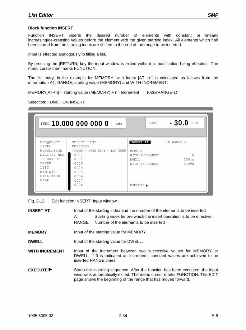
List Editor SMP
1035.5005.02 2.34 E-8
Block function INSERT
Function INSERT inserts the desired number of elements with constant or linearlyincreasing/de-creasing values before the element with the given starting index. All elements which hadbeen stored from the starting index are shifted to the end of the range to be inserted.
Input is effected analogously to filling a list.
By pressing the [RETURN] key the input window is exited without a modification being effected. Themenu cursor then marks FUNCTION.
The list entry, in the example for MEMORY, with index [AT +n] is calculated as follows from theinformation AT, RANGE, starting value (MEMORY) and WITH INCREMENT:
MEMORY[AT+n] = starting value (MEMORY) + n · Increment | (0≤n≤RANGE-1)
Selection: FUNCTION INSERT
FREQUENCYLEVELMODULATIONDIGITAL MODLF OUTPUTSWEEPLISTMEM SEQUTILITIESHELP
FREQ 10.000 000 000 0 GHz LEVEL - 30.0 dBm
SELECT LIST...FUNCTION-INDEX - FREE 2041 - LEN 2055 0001 0002 0003 0004 0005 0006 0007 0008
INSERT AT 10 RANGE 2
MEMORY 1WITH INCREMENT 0DWELL 100msWITH INCREMENT 0.0ms
EXECUTE
Fig. 2-12 Edit function INSERT: Input window
INSERT AT Input of the starting index and the number of the elements to be inserted.
AT Starting index before which the insert operation is to be effective.
RANGE Number of the elements to be inserted
MEMORY Input of the starting value for MEMORY.
DWELL Input of the starting value for DWELL.
WITH INCREMENT Input of the increment between two successive values for MEMORY orDWELL. If 0 is indicated as increment, constant values are achieved to beinserted RANGE times.
EXECUTE Starts the inserting sequence. After the function has been executed, the inputwindow is automatically exited. The menu cursor marks FUNCTION. The EDITpage shows the beginning of the range that has moved forward.
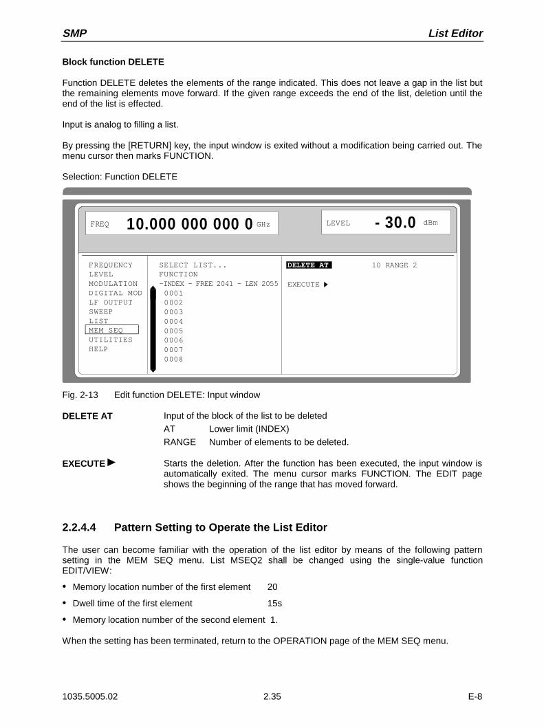
SMP List Editor
1035.5005.02 2.35 E-8
Block function DELETE
Function DELETE deletes the elements of the range indicated. This does not leave a gap in the list butthe remaining elements move forward. If the given range exceeds the end of the list, deletion until theend of the list is effected.
Input is analog to filling a list.
By pressing the [RETURN] key, the input window is exited without a modification being carried out. Themenu cursor then marks FUNCTION.
Selection: Function DELETE
FREQUENCYLEVELMODULATIONDIGITAL MODLF OUTPUTSWEEPLISTMEM SEQUTILITIESHELP
FREQ 10.000 000 000 0 GHz LEVEL - 30.0 dBm
SELECT LIST...FUNCTION-INDEX - FREE 2041 - LEN 2055 0001 0002 0003 0004 0005 0006 0007 0008
DELETE AT 10 RANGE 2
EXECUTE
Fig. 2-13 Edit function DELETE: Input window
DELETE AT Input of the block of the list to be deleted
AT Lower limit (INDEX)
RANGE Number of elements to be deleted.
EXECUTE Starts the deletion. After the function has been executed, the input window isautomatically exited. The menu cursor marks FUNCTION. The EDIT pageshows the beginning of the range that has moved forward.
2.2.4.4 Pattern Setting to Operate the List Editor
The user can become familiar with the operation of the list editor by means of the following patternsetting in the MEM SEQ menu. List MSEQ2 shall be changed using the single-value functionEDIT/VIEW:
• Memory location number of the first element 20
• Dwell time of the first element 15s
• Memory location number of the second element 1.
When the setting has been terminated, return to the OPERATION page of the MEM SEQ menu.

List Editor SMP
1035.5005.02 2.36 E-8
At the beginning of the operation sequence, menu MEM SEQ is called. List MSEQ2 is active. The menucursor marks a parameter of the setting menu on the OPERATION page (c.f. Fig. 2-14).
FREQUENCYLEVELMODULATIONDIGITAL MODLF OUTPUTSWEEPLISTMEM SEQUTILITIESHELP
LEVEL - 30.0 10.000 000 000 0 dBm
MODE OFF AUTO SINGLE STEP EXT-SINGLE EXT-STEP
RESET SEQUENCE
CURRENT INDEX 1
SELECT LIST... CURRENT: MSEQ2DELETE LIST...FUNCTION FILL INSERT DELETE EDIT/VIEW
FREQ GHz
Fig. 2-14 Starting point of the pattern setting
Operating steps Explanations
.FUNCTION.
MENU / VARIATION
SELECT
MENU / VARIATION Select the FUNCTION menu item.
. EDIT/VIEW .
MENU / VARIATION
SELECT
MENU / VARIATION Select single-value functionEDIT/VIEW.
The EDIT page of the MEM SEQmenu is called. The menu cursormarks the index of the first elementof list SEQ2.
SELECTSet the menu cursor to the memorylocation number value of the firstelement (c.f. Fig. 2-15,A).
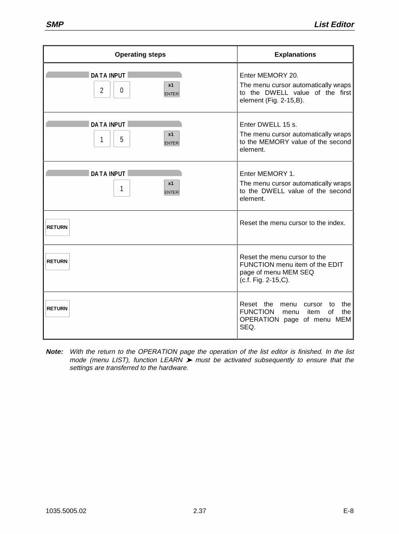
SMP List Editor
1035.5005.02 2.37 E-8
Operating steps Explanations
DA TA INPUT
2 0x1
ENTER
Enter MEMORY 20.
The menu cursor automatically wrapsto the DWELL value of the firstelement (Fig. 2-15,B).
DA TA INPUT
1 5x1
ENTER
Enter DWELL 15 s.
The menu cursor automatically wrapsto the MEMORY value of the secondelement.
DA TA INPUT
1x1
ENTER
Enter MEMORY 1.
The menu cursor automatically wrapsto the DWELL value of the secondelement.
RETURNReset the menu cursor to the index.
RETURNReset the menu cursor to theFUNCTION menu item of the EDITpage of menu MEM SEQ(c.f. Fig. 2-15,C).
RETURNReset the menu cursor to theFUNCTION menu item of theOPERATION page of menu MEMSEQ.
Note: With the return to the OPERATION page the operation of the list editor is finished. In the listmode (menu LIST), function LEARN must be activated subsequently to ensure that thesettings are transferred to the hardware.

List Editor SMP
1035.5005.02 2.38 E-8
Fig. 2-15, a to c Pattern setting - Edition of a list

SMP Save/Recall
1035.5005.02 2.39 E-8
2.2.5 Save/Recall - Storing/Calling of Instrument Settings
50 complete instrument settings can be stored in memory locations 1 to 50.
Operating steps Explanations
DATA INP UTx1
ENTER21SAVE
Store current instrument setting inmemory location 12.
DATA INP UTx1
ENTER21RCL
Call instrument setting of memorylocation 12.
The digital display during a save or recall entry is faded in a window.
Memory location 0 has a special function. Here the instrument setting which was current prior to the lastmemory recall and prior to a preset setting is automatically stored. This permits the resetting ofinstrument settings which have inadvertently been deleted using Recall 0.
If an instrument setting is stored in which a sweep was switched on, the sweep is started using therecall.
The parameter EXCLUDE FROM RCL in the FREQUENCY and LEVEL-LEVEL menus determineswhether the saved RF frequency and RF level are loaded when an instrument setting is loaded, orwhether the current settings are maintained.
Store IEC-bus command: "*SAV 12"
Call IEC-bus command: "*RCL 12"
Note: The contents of lists, as they are used for the LIST mode or for user correction (UCOR), is notsaved in the SAVE memory. It is stored under the respective list name and can be called. Ifinstrument settings are called which go back to list data such as level setting using UCOR, thecurrent list contents is used. If this has been altered, it is not identical to the list contents at thepoint of storing any more.
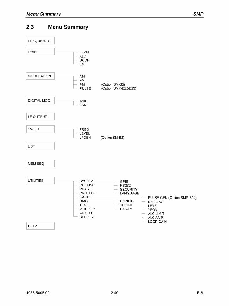
Menu Summary SMP
1035.5005.02 2.40 E-8
2.3 Menu Summary
FREQUENCY
LEVELALCUCOREMF
LEVEL
AMFMPMPULSE
MODULATION
ASKFSK
DIGITAL MOD
LF OUTPUT
FREQ LEVEL LFGEN (Option SM-B2)
SWEEP
LIST
MEM SEQ
SYSTEMREF OSCPHASEPROTECTCALIBDIAGTESTMOD KEYAUX I/OBEEPER
UTILITIES
HELP
GPIBRS232SECURITYLANGUAGE
CONFIGTPOINTPARAM
PULSE GEN (Option SMP-B14)REF OSCLEVELYFOMALC LIMITALC AMPLOOP GAIN
(Option SM-B5)(Option SMP-B12/B13)

SMP RF Frequency
1035.5005.02 2.41 E-8
2.4 RF Frequency
The frequency of the RF output signal can be set directly using the [FREQ] key or by accessing menuFREQUENCY.
In the header field of the display, the frequency of the RF output signal is indicated under FREQ.In the case of frequency settings opened by means of the [FREQ] key, the value entered directly is thefrequency of the RF output signal.
The input value of frequency settings effected in the FREQUENCY menu considers the offset incalculation. This offers the possibility of entering the desired output frequency of these series-connectedinstruments in the menu. The SMP then changes the RF output frequency correspondingly. Offset andmultiplier can also be entered in the FREQUENCY menu.
Note: Further settings: Frequency sweep Menu SWEEPLF frequency Menu MODULATION
Menu LF-OUTPUT
int./ext. reference frequency Menu UTILITIES-REF OSC
Phase of the output signal Menu UTILITIES-PHASE
Menu selection: FREQUENCY
FREQUENCYLEVELMODULATIONDIGITAL MODLF OUTPUTSWEEPLISTMEM SEQUTILITIESHELP
FREQUENCYOFFSETMULTIPLIER 1
KNOB STEP USERKNOB STEPEXCLUDE FROM RCL
10.000 000 000 0 GHz 0.0 Hz
FREQ 10.000 000 000 0 GHz LEVEL - 30.0 dBm
1. 000 000 0 MHz DECIMAL USER ON OFF
Fig. 2-16 Menu FREQUENCY (preset setting)
FREQUENCY Input value of the RF frequency considering the OFFSET and MULTIPLIERinput values. The frequency of the RF output signal is determined by the inputvalues FREQUENCY, OFFSET and MULTIPLIER (cf. Section "FrequencyOffset and Multiplier").
IEC-bus short command :FREQ 10E9
OFFSET Input value of the frequency offset, e.g., of a series-connected mixer (cf.Section "Frequency Offset and Multiplier").
IEC-bus short command :FREQ:OFFS 0
MULTIPLIER Input value of a multiplication factor, e.g., of a series-connected frequencymultiplier (cf. Section "Frequency Offset and Multiplier").
IEC-bus short command :FREQ:MULT 1

RF Frequency SMP
1035.5005.02 2.42 E-8
KNOB STEP USER Input value of the step width for frequency variation using the rotary knob. TheRF frequency is varied in the step width entered if KNOB STEP is set to USER.
IEC-bus short command :FREQ:STEP 1MHz
KNOB STEP DECIMAL: Variation step width corresponding to the position of the digitcursor.
USER: "User Defined", variation step width as entered under KNOBSTEP USER .
EXCLUDE FROM RCL OFF Default setting. The saved frequency is loaded as well wheninstrument settings are loaded with the [RCL] key or with amemory sequence.
IEC-bus short command :FREQ:RCL INCL
ON The RF frequency is not loaded when instrument settings areloaded, the current frequency settings are maintained.
IEC-bus short command :FREQ:RCL EXCL
2.4.1 Frequency Offset and Multiplier
The SMP offers the possibility of entering an offset and multiplier of possibly series-connectedinstruments in the FREQUENCY menu. The indication/input value under FREQUENCY considers thisentries and represents the frequency value of the RF signal at the output of these instruments (cf. Fig.2-17). If frequency offset as well as multiplier have been entered, it is taken for granted in calculating thevalues that the RF signal is multiplied first and then the offset is added.
Hence the frequency of the new RF output signal is calculated from the entries FREQUENCY, OFFSETand MULTILIER according to the formula:
RF-output frequency = (FREQUENCY – OFFSET) / MULTIPLIER
Offset and multiplier entries do not have an influence on the RF output signal of the SMP. I. e., an entrydoes not change the RF-output frequency but only the FREQUENCY value indicated in theFREQUENCY menu.
The RF output frequency of the SMP is indicated in the header field of the display. It can be entereddirectly using the [FREQ] key, i.e. without considering the offset and multiplier.
The offset setting also remains effective with the frequency sweep.
Input value OFFSET
L.O.
RF output frequency
Mixer
Input value FREQUENCY
× Ø
SMP
Input value MULTIPLIER
RF output frequency
Frequency multiplier
Input value FREQUENCY
× Ø
SMP
Fig. 2-17 Example of a circuit with frequency offset or multiplier
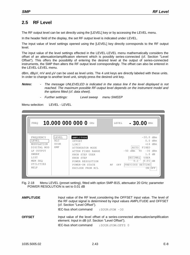
SMP RF Level
1035.5005.02 2.43 E-8
2.5 RF Level
The RF output level can be set directly using the [LEVEL] key or by accessing the LEVEL menu.
In the header field of the display, the set RF output level is indicated under LEVEL.
The input value of level settings opened using the [LEVEL] key directly corresponds to the RF outputlevel.
The input value of the level settings effected in the LEVEL-LEVEL menu mathematically considers theoffset of an attenuation/amplification element which is possibly series-connected (cf. Section "LevelOffset"). This offers the possibility of entering the desired level at the output of series-connectedinstruments, the SMP then alters the RF output level correspondingly. The offset can also be entered inthe LEVEL-LEVEL menu.
dBm, dBµV, mV and µV can be used as level units. The 4 unit keys are directly labeled with these units.In order to change to another level unit, simply press the desired unit key.
Notes: - The message UNLEVELED is indicated in the status line if the level displayed is notreached. The maximum possible RF-output level depends on the instrument model andthe options fitted (cf. data sheet).
- Further settings: Level sweep menu SWEEP
Menu selection: LEVEL - LEVEL
FREQUENCYLEVELMODULATIONDIGITAL MODLF OUTPUTSWEEPLISTMEM SEQUTILITIESHELP
LEVELALCUCOREMF
AMPLITUDEOFFSETLIMIT ATTENUATOR MODEATTEN FIXED RANGEKNOB STEP USERKNOB STEPPOWER RESOLUTIONPOWER-ON STATE RF OFF PREVIOUS SETTING EXCLUDE FROM RCL ON OFF
FREQ 10.000 000 000 0 GHz LEVEL - 30.00 dBm
-30.0 dBm 0.0 dBm +16 dBm AUTO FIXED-50 dBm TO -30 dBm 1.0 dB DECIMAL USER 0.1 0.01 dB
Fig. 2-18 Menu LEVEL (preset setting), fitted with option SMP-B15, attenuator 20 GHz; parameter POWER RESOLUTION is set to 0.01 dB
AMPLITUDE Input value of the RF level considering the OFFSET input value. The level ofthe RF output signal is determined by input values AMPLITUDE and OFFSET(cf. Section "Level Offset").
IEC-bus short command :SOUR:POW -30
OFFSET Input value of the level offset of a series-connected attenuation/amplificationelement. Input in dB (cf. Section "Level Offset").
IEC-bus short command :SOUR:POW:OFFS 0
RF Level SMP
1035.5005.02 2.44 E-8
LIMIT Input value of level limitation. This value indicates the upper limit of the level atthe RF output connector. If a level above this limit is attempted to be set, awarning is displayed in the status line.
IEC-bus short command :SOUR:POW:LIM 16 dBm
ATTENUATOR MODE AUTO Normal operation. The attenuator switching mechanically switchesin steps of 5 dB, the switching points being fixed.
IEC-bus short command :OUTP:AMOD AUTO
FIXED Level settings are effected in a 20-dB range without switching theattenuator (cf. Section "Interrupt-free Level Setting").
IEC-bus short command :OUTP:AMOD FIX
ATTEN FIXED RANGE Indication of the level range in which the level is set without interruption in the"ATTENUATOR MODE FIXED" operating mode.
KNOB STEP USER Input value of the step width for level variation using the rotary knob. The RFlevel is varied in the step width entered if KNOB STEP is set to USER.
IEC-bus short command :SOUR:POW:STEP 1
KNOB STEP DECIMAL Variation step width according to the position of the digit cursor.
USER User Defined, variation step width as entered under KNOB STEPUSER.
POWER RESOLUTION 0.1 dB The resolution of the LEVEL indication is set to 0.1 dB.
0.01 dB The resolution of the LEVEL indication is set to 0.01 dB.
POWER-ON STATE Selection of the state the RF output is to assume after power-on of the unit
RF OFF Output is switched off
PREVIOUS SETTING Same state as before switch-off
IEC-bus short command :OUTP:PON ON
EXCLUDE FROM RCL OFF Default setting. The saved RF level is loaded as well wheninstrument settings are loaded with the [RCL] key or with a memorysequence.
IEC-bus short command :SOUR:POW:RCL INCL
ON The RF level is not loaded when instrument settings are loaded,the current level settings are maintained.
IEC-bus short command :SOUR:POW:RCL EXCL
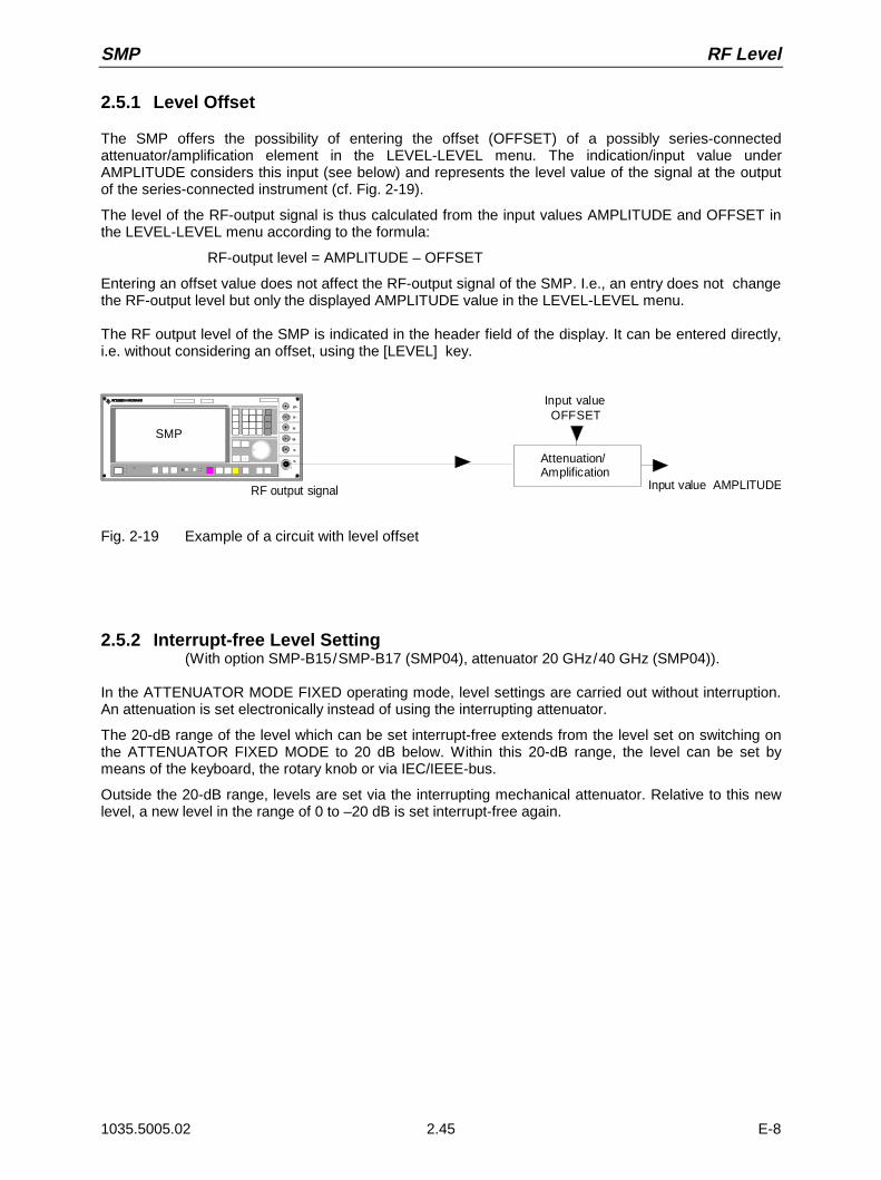
SMP RF Level
1035.5005.02 2.45 E-8
2.5.1 Level Offset
The SMP offers the possibility of entering the offset (OFFSET) of a possibly series-connectedattenuator/amplification element in the LEVEL-LEVEL menu. The indication/input value underAMPLITUDE considers this input (see below) and represents the level value of the signal at the outputof the series-connected instrument (cf. Fig. 2-19).
The level of the RF-output signal is thus calculated from the input values AMPLITUDE and OFFSET inthe LEVEL-LEVEL menu according to the formula:
RF-output level = AMPLITUDE – OFFSET
Entering an offset value does not affect the RF-output signal of the SMP. I.e., an entry does not changethe RF-output level but only the displayed AMPLITUDE value in the LEVEL-LEVEL menu.
The RF output level of the SMP is indicated in the header field of the display. It can be entered directly,i.e. without considering an offset, using the [LEVEL] key.
Input valueOFFSET
RF output signal
Attenuation/Amplification
Input value AMPLITUDE
× Ø
SMP
Fig. 2-19 Example of a circuit with level offset
2.5.2 Interrupt-free Level Setting(With option SMP-B15/SMP-B17 (SMP04), attenuator 20 GHz/40 GHz (SMP04)).
In the ATTENUATOR MODE FIXED operating mode, level settings are carried out without interruption.An attenuation is set electronically instead of using the interrupting attenuator.
The 20-dB range of the level which can be set interrupt-free extends from the level set on switching onthe ATTENUATOR FIXED MODE to 20 dB below. Within this 20-dB range, the level can be set bymeans of the keyboard, the rotary knob or via IEC/IEEE-bus.
Outside the 20-dB range, levels are set via the interrupting mechanical attenuator. Relative to this newlevel, a new level in the range of 0 to –20 dB is set interrupt-free again.

RF Level SMP
1035.5005.02 2.46 E-8
2.5.3 Level Control (ALC)
Menu LEVEL-ALC offers access to settings for level control.
Level control can be deactivated and various bandwidths of the level control can be switched on.
Switching off level control (ALC STATE OFF) switches over the internal level control into asample-and-hold operation. In this operating mode, level control is automatically switched on for a shortperiod of time after every level and frequency setting, and then the level control is held at the valueachieved. Switching off the level control is used with multi-transmitter measurements to achieve a largerintermodulation ratio.
The basic functions of level control are shown in Fig. 2-20.
Synthesizer PIN-controlelement RF-amplifier RF-attenuator
RF-outputOption SMP-B15/B17
Integrator Differentialamplifier
Internal level control
External level control
EXT ALC-inputReference voltage
Internaldetector
+-
Fig. 2-20 Basic principle of level control of the SMP
An application example for external level control is shown in Fig. 2-21.
× Ø
SMP
Power meter NRVS Signal generator SMP
EXT ALC
Signal divider ordirectional coupler
DUT
Power sensor
RF
DC
DC FREQ V/GHz
Fig. 2-21 Example of external power control using a power meter
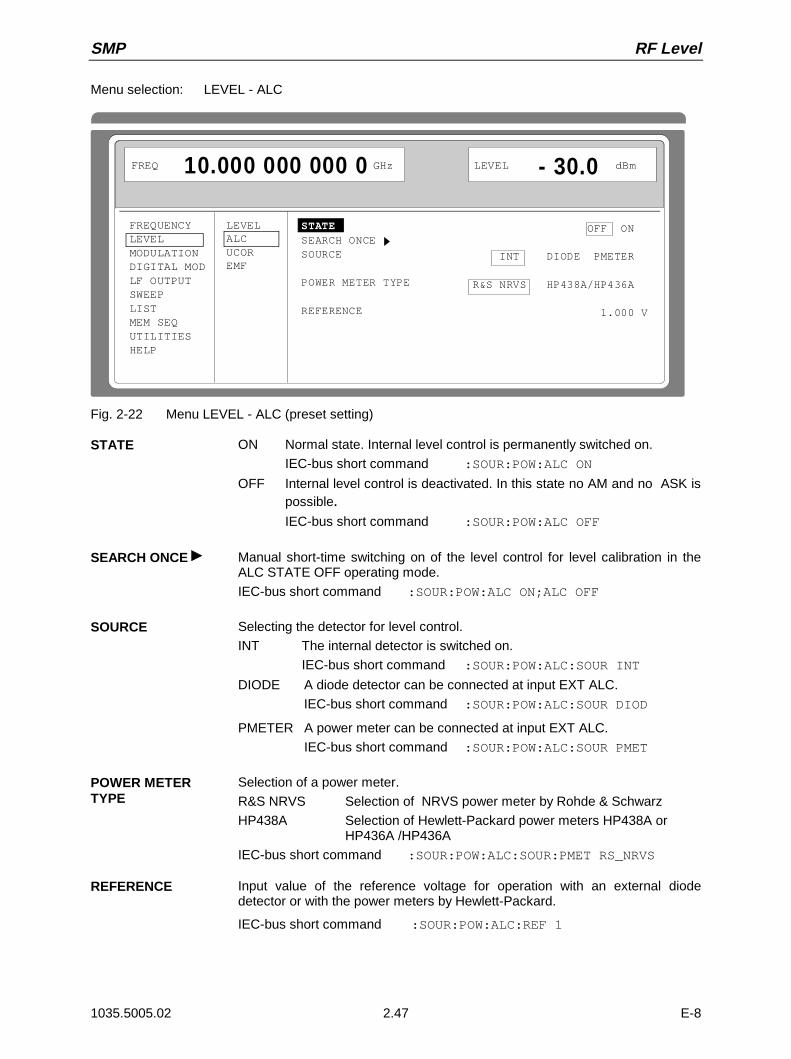
SMP RF Level
1035.5005.02 2.47 E-8
Menu selection: LEVEL - ALC
FREQUENCYLEVELMODULATIONDIGITAL MODLF OUTPUTSWEEPLISTMEM SEQUTILITIESHELP
LEVELALCUCOREMF
STATESEARCH ONCESOURCE
POWER METER TYPE
REFERENCE
FREQ 10.000 000 000 0 GHz LEVEL - 30.0 dBm
OFF ON
INT DIODE PMETER
R&S NRVS HP438A/HP436A
1.000 V
Fig. 2-22 Menu LEVEL - ALC (preset setting)
STATE ON Normal state. Internal level control is permanently switched on.
IEC-bus short command :SOUR:POW:ALC ON
OFF Internal level control is deactivated. In this state no AM and no ASK ispossible.IEC-bus short command :SOUR:POW:ALC OFF
SEARCH ONCE Manual short-time switching on of the level control for level calibration in theALC STATE OFF operating mode.
IEC-bus short command :SOUR:POW:ALC ON;ALC OFF
SOURCE Selecting the detector for level control.
INT The internal detector is switched on.
IEC-bus short command :SOUR:POW:ALC:SOUR INT
DIODE A diode detector can be connected at input EXT ALC.
IEC-bus short command :SOUR:POW:ALC:SOUR DIOD
PMETER A power meter can be connected at input EXT ALC.
IEC-bus short command :SOUR:POW:ALC:SOUR PMET
POWER METERTYPE
Selection of a power meter.
R&S NRVS Selection of NRVS power meter by Rohde & Schwarz
HP438A Selection of Hewlett-Packard power meters HP438A or HP436A /HP436A
IEC-bus short command :SOUR:POW:ALC:SOUR:PMET RS_NRVS
REFERENCE Input value of the reference voltage for operation with an external diodedetector or with the power meters by Hewlett-Packard.
IEC-bus short command :SOUR:POW:ALC:REF 1

RF Level SMP
1035.5005.02 2.48 E-8
2.5.4 User Correction (UCOR)
Function "User Correction" can be used to create and activate lists in which arbitrary RF frequencies areassigned level correction values.
Up to 10 lists with a total of 160 correction values can be compiled. For frequencies which are notincluded in the list the level correction is determined by means of interpolation of the nearest correctionvalues.
When user correction is switched on, the LEVEL indication is completed by the indication UCOR (UserCorrection) in the header field of the display. The RF output level is the sum of both values.
Output Level = LEVEL + UCOR
If the offset setting is used at the same time, the LEVEL indication value is the difference of the inputvalues AMPLITUDE and OFFSET of the menu LEVEL.
AMPLITUDE − OFFSET = LEVEL
The user correction is effective in all operating modes if switched on.
Menu selection: LEVEL - UCOR
FREQUENCYLEVELMODULATIONDIGITAL MODLF OUTPUTSWEEPLISTMEM SEQUTILITIESHELP
LEVELALCUCOREMF
STATE
POWER METER TYPE R&S-NRVD R&S-NRVS HP437MEASURE CONNECTION VIA POWER METER
SELECT LIST... CURRENT: UCOR1DELETE LIST...FUNCTION FILL INSERT DELETE EDIT/VIEW
FREQ 10.000 000 000 0 GHzLEVEL - 27.0 dBm
UCOR + 1.9 dB
OFF ON
Fig. 2-23 Menu LEVEL - UCOR - OPERATION page
STATE Switching on/off user correction.
IEC-bus short command :SOUR:CORR ON
POWER METERTYPE
Selection of a power meter for automatic level correction (see next section,"Automatic Level Correction").
R&S NRVD Selection of Rohde & Schwarz power meter NRVD
R&S NRVS Selection of Rohde & Schwarz power meter NRVS
HP437 Selection of power meter HP437 by Hewlett-Packard
MEASURECORRECTION VIAPOWER METER
Start of automatic level correction (see next section, "Automatic LevelCorrection").
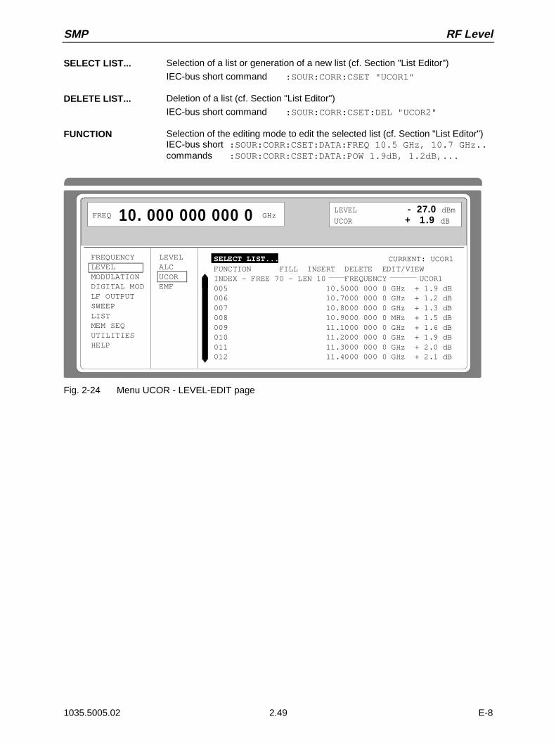
SMP RF Level
1035.5005.02 2.49 E-8
SELECT LIST... Selection of a list or generation of a new list (cf. Section "List Editor")
IEC-bus short command :SOUR:CORR:CSET "UCOR1"
DELETE LIST... Deletion of a list (cf. Section "List Editor")
IEC-bus short command :SOUR:CORR:CSET:DEL "UCOR2"
FUNCTION Selection of the editing mode to edit the selected list (cf. Section "List Editor")IEC-bus short :SOUR:CORR:CSET:DATA:FREQ 10.5 GHz, 10.7 GHz..commands :SOUR:CORR:CSET:DATA:POW 1.9dB, 1.2dB,...
FREQUENCYLEVELMODULATIONDIGITAL MODLF OUTPUTSWEEPLISTMEM SEQUTILITIESHELP
LEVELALCUCOREMF
FREQ 10. 000 000 000 0 GHzLEVEL - 27.0 dBmUCOR + 1 .9 dB
SELECT LIST... CURRENT: UCOR1
FUNCTION FILL INSERT DELETE EDIT/VIEWINDEX - FREE 70 - LEN 10 FREQUENCY UCOR1005 10.5000 000 0 GHz + 1.9 dB006 10.7000 000 0 GHz + 1.2 dB007 10.8000 000 0 GHz + 1.3 dB008 10.9000 000 0 MHz + 1.5 dB009 11.1000 000 0 GHz + 1.6 dB010 11.2000 000 0 GHz + 1.9 dB011 11.3000 000 0 GHz + 2.0 dB012 11.4000 000 0 GHz + 2.1 dB
Fig. 2-24 Menu UCOR - LEVEL-EDIT page

RF Level SMP
1035.5005.02 2.50 E-8
2.5.5 Automatic level correction
Fig. 2-25 shows a typical application using automatic level correction.
Power meter NRVS
× Ø
IEC/IEE
Objet en essai× Ø
UCOR activ
Signal generator SMPSignal generator SMP
Power sensor DUT
IEC/IEE
RF RF
Fig. 2-25 a Determining the correction values Fig. 2-25 b Measurement
The settings for automatic level correction can be accessed via the LEVEL-UCOR menu.
Automatic level correction is activated with MEASURE CORRECTION VIA POWER METER . Thepower meter used must be selected first via POWER METER TYPE.
When the automatic level correction is started, the instrument displays a warning:
ATTENTION:This function overwrites the level values
of your current UCOR List!
Automatic level correction can be continued by pressing the [SELECT] key. It is aborted by pressing[RETURN] .
The IEC-bus address of the power meter and the power sensor used are indicated while the measuredvalues are read into the UCOR list.
Attention: The frequencies of the UCOR list must lie inside the frequency range of the sensor.Frequencies located outside the frequency range of the sensor lead to faultymeasurements.
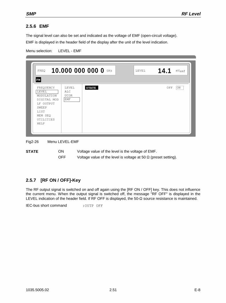
SMP RF Level
1035.5005.02 2.51 E-8
2.5.6 EMF
The signal level can also be set and indicated as the voltage of EMF (open-circuit voltage).
EMF is displayed in the header field of the display after the unit of the level indication.
Menu selection: LEVEL - EMF
FREQUENCYLEVELMODULATIONDIGITAL MODLF OUTPUTSWEEPLISTMEM SEQUTILITIESHELP
LEVELALCUCOREMF
STATE
FREQ 10.000 000 000 0 GHz LEVEL 14.1 mV
FM
OFF ON
emf
Fig2-26 Menu LEVEL-EMF
STATE ON Voltage value of the level is the voltage of EMF.
OFF Voltage value of the level is voltage at 50 Ω (preset setting).
2.5.7 [RF ON / OFF]-Key
The RF output signal is switched on and off again using the [RF ON / OFF] key. This does not influencethe current menu. When the output signal is switched off, the message "RF OFF" is displayed in theLEVEL indication of the header field. If RF OFF is displayed, the 50-Ω source resistance is maintained.
IEC-bus short command :OUTP OFF
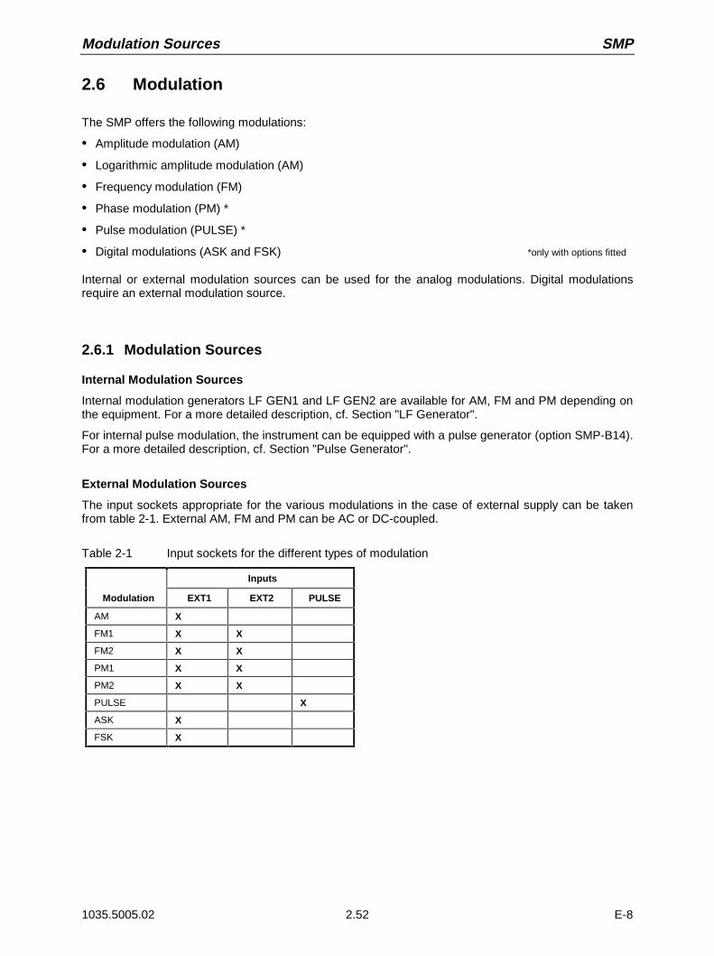
Modulation Sources SMP
1035.5005.02 2.52 E-8
2.6 Modulation
The SMP offers the following modulations:
• Amplitude modulation (AM)
• Logarithmic amplitude modulation (AM)
• Frequency modulation (FM)
• Phase modulation (PM) *
• Pulse modulation (PULSE) *
• Digital modulations (ASK and FSK) *only with options fitted
Internal or external modulation sources can be used for the analog modulations. Digital modulationsrequire an external modulation source.
2.6.1 Modulation Sources
Internal Modulation Sources
Internal modulation generators LF GEN1 and LF GEN2 are available for AM, FM and PM depending onthe equipment. For a more detailed description, cf. Section "LF Generator".
For internal pulse modulation, the instrument can be equipped with a pulse generator (option SMP-B14).For a more detailed description, cf. Section "Pulse Generator".
External Modulation Sources
The input sockets appropriate for the various modulations in the case of external supply can be takenfrom table 2-1. External AM, FM and PM can be AC or DC-coupled.
Table 2-1 Input sockets for the different types of modulation
Inputs
Modulation EXT1 EXT2 PULSE
AM X
FM1 X X
FM2 X X
PM1 X X
PM2 X X
PULSE X
ASK X
FSK X
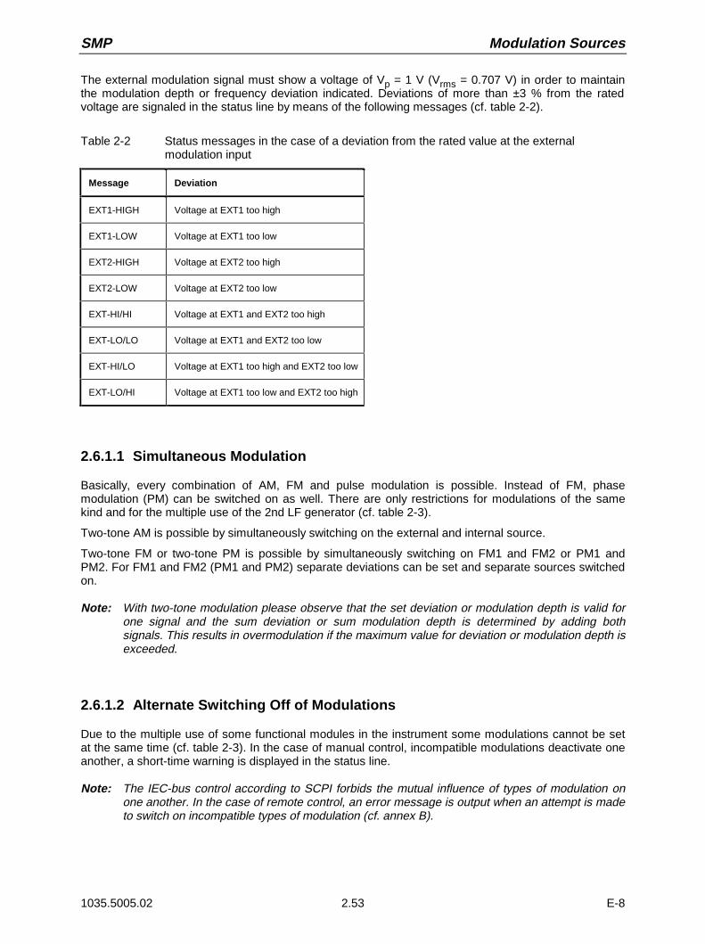
SMP Modulation Sources
1035.5005.02 2.53 E-8
The external modulation signal must show a voltage of Vp = 1 V (Vrms = 0.707 V) in order to maintainthe modulation depth or frequency deviation indicated. Deviations of more than ±3 % from the ratedvoltage are signaled in the status line by means of the following messages (cf. table 2-2).
Table 2-2 Status messages in the case of a deviation from the rated value at the externalmodulation input
Message Deviation
EXT1-HIGH Voltage at EXT1 too high
EXT1-LOW Voltage at EXT1 too low
EXT2-HIGH Voltage at EXT2 too high
EXT2-LOW Voltage at EXT2 too low
EXT-HI/HI Voltage at EXT1 and EXT2 too high
EXT-LO/LO Voltage at EXT1 and EXT2 too low
EXT-HI/LO Voltage at EXT1 too high and EXT2 too low
EXT-LO/HI Voltage at EXT1 too low and EXT2 too high
2.6.1.1 Simultaneous Modulation
Basically, every combination of AM, FM and pulse modulation is possible. Instead of FM, phasemodulation (PM) can be switched on as well. There are only restrictions for modulations of the samekind and for the multiple use of the 2nd LF generator (cf. table 2-3).
Two-tone AM is possible by simultaneously switching on the external and internal source.
Two-tone FM or two-tone PM is possible by simultaneously switching on FM1 and FM2 or PM1 andPM2. For FM1 and FM2 (PM1 and PM2) separate deviations can be set and separate sources switchedon.
Note: With two-tone modulation please observe that the set deviation or modulation depth is valid forone signal and the sum deviation or sum modulation depth is determined by adding bothsignals. This results in overmodulation if the maximum value for deviation or modulation depth isexceeded.
2.6.1.2 Alternate Switching Off of Modulations
Due to the multiple use of some functional modules in the instrument some modulations cannot be setat the same time (cf. table 2-3). In the case of manual control, incompatible modulations deactivate oneanother, a short-time warning is displayed in the status line.
Note: The IEC-bus control according to SCPI forbids the mutual influence of types of modulation onone another. In the case of remote control, an error message is output when an attempt is madeto switch on incompatible types of modulation (cf. annex B).

Modulation Sources SMP
1035.5005.02 2.54 E-8
Table 2-3 Modulations which cannot be operated simultaneously
AMINT1
AMINT2
AMEXT1
ASK
FM1INT1
FM1EXT1
FM1EXT2
FM1FSK
FM2INT2
FM2EXT1
FM2EXT2
FM2FSK
PM1INT1
PM1EXT1
PM1EXT2
PM2INT2
PM2EXT1
PM2EXT2
AM INT1
AM INT2
AM EXT1 X X
ASK X X
FM1 INT1 X X X X X X
FM1 EXT1 X X X X X X X X
FM1 EXT2 X X X X X X
FM1 FSK X X X X X X X X
FM2 INT2 X X X X X X
FM2 EXT1 X X X X X X X X
FM2 EXT2 X X X X X X
FM2 FSK X X X X X X X X
PM1 INT1 X X X X X X X X
PM1 EXT1 X X X X X X X X
PM1 EXT2 X X X X X X X X
PM2 INT2 X X X X X X X X
PM2 EXT1 X X X X X X X X
PM2 EXT2 X X X X X X X X
X Mutual switching off in the case of manual control Switching off by means of 1-out-of-n selection
2.6.1.3 [MOD ON/OFF] Key
The modulations can directly be switched on/off using the key or by accessing the MODULATIONmenu. When switching on using the [MOD ON/OFF] key, the modulation sources which are set in themodulation menus are used.
The [MOD ON/OFF] key can either be effective for all modulations or for a selected modulation. Theselection for which modulation the [MOD ON/OFF] key is effective is made in the UTILITIES-MOD KEYmenu.
Once a certain type of modulation has been selected, it is switched on or off each time that the [MODON/OFF] key is pressed.
If "all modulations" are selected, the [MOD ON/OFF] key has the following effect:
• At least one modulation is active:Pressing the [MOD ON/OFF] key switches off all active modulations. Which modulations were activeis stored.
• No modulation is active:Pressing the [MOD ON/OFF] key switches on the modulations which were last switched off using the[MOD ON/OFF] key.

SMP Analog Modulations
1035.5005.02 2.55 E-8
2.6.2 Analog Modulation
2.6.2.1 LF-Generator
The SMP is equipped with a fixed-frequency generator as internal modulation source as a standard. Thegenerator supplies sinusoidal signals of the frequencies of 0.4, 1, 3 and 15 kHz.In addition to the standard equipment, the SMP can be equipped with the optional LF modulation sourceSM-B2, LF-generator.
It is possible to fit two optional modulation sources unless option SM-B3, pulse modulator, is fitted. If twooptions are fitted, the access to the internal standard generator is eliminated. The different possibilitiesof modulation generator fitting are visible from Table 2-4:
Table 2-4 Modulation generators as component parts
LF-Generator 1 LF-Generator 2
Standard generator ---
Standard generator Option SM-B2, LF-generator
Option SM-B2, LF-generator Option SM-B2, LF-generator
The shape and frequency of the internal modulation signals can be selected in one of the modulationmenus ( AM, FM, PM) as well as in the LF-output menu.
Notes: - In conformance to the possibilities of the modulation generator options fitted, there aredifferences in the modulation menus for AM, FM and PM.
- The settings LFGEN SHAPE NOI and LF sweep deactivate one another.

Analog Modulations SMP
1035.5005.02 2.56 E-8
2.6.2.2 Amplitude Modulation
Menu MODULATION-AM offers access to settings for amplitude modulation.
Notes: - The maximal level guaranteed of the SMP is different depending on model and options fitted(cf. data sheet). The specified AM data are only valid up to 6 dB under the respectivemaximal level. If this value is exceeded, the AM data are only guaranteed for a linearlydecreasing modulation depth.
– When a modulation depth is set that is too high, "WARNING" is displayed in the status line orthe message "WARN -221 Settings conflict; modulation forces peak level into overrange" isdisplayed after pressing the ERROR key.
Menu selection: MODULATION- AM
FREQUENCYLEVELMODULATIONDIGITAL MODLF OUTPUTSWEEPLISTMEM SEQUTILITIESHELP
AMFMPMPULSE
AM DEPTHAM SOURCESCAN STATEAM EXT COUPLINGEXT1 IMPEDANCE
LFGEN1 FREQ
LFGEN2 FREQLFGEN2 SHAPE
FREQ 10.000 000 000 0 GHz LEVEL - 30.0 dBm
30.0 %OFF EXT1 LFGEN1 LFGEN2 ON OFF AC DC
600 100k Ω
0.4k 1k 3k 15k Hz
1.000 0 kHz SIN SQR TRI NOI
Fig. 2-27 Menu MODULATION-AM (preset setting), fitted with option SM-B2, LF-generator (LFGEN2)
AM DEPTHorSCAN SENSITIVITY
Input value of the modulation depthorInput value of the scan sensitivity (for SCAN STATE ON).IEC-bus short command :SOUR:AM 30PCT / :AM:SCAN:SENS 10dB
AM SOURCE Selection of the modulation source.IEC-bus short command :SOUR:AM:SOUR INT1; STAT ON
SCAN STATE Switching on and off the logarithmic amplitude modulationIEC-bus short command :SOUR:AM:SCAN ON
AM EXT COUPLING Selection of the kind of coupling AC or DC for external supply (input EXT1).IEC-bus short command :SOUR:AM:EXT:COUP AC
EXT1 IMPEDANCE Selection of the input impedance of the external input EXT1IEC-bus short command :SOUR:AM:EXT:IMP 100kOhm
LFGEN1 FREQ Selection of the frequency of the 1st LF generator.IEC-bus short command :SOUR:AM:INT1:FREQ 1kHz
LFGEN2 FREQ Input value of the frequency of the 2nd LF generator.IEC-bus short command :SOUR:AM:INT2:FREQ 1kHz
LFGEN2 SHAPE Selection of the shape of the 2nd LF generator.
IEC-bus short command :SOUR2:FUNC SIN

SMP Analog Modulations
1035.5005.02 2.57 E-8
2.6.2.3 Frequency Modulation
Operating modes
If the option SM-B5, FM/PM-modulator, is fitted, three operating modes for frequeny modulation of theRF-signal are available. The operating mode selected determines the modulation frequency range, themaximum frequency deviation and the frequency accuracy (see Table 2-5).
Without the option, frequency modulation of the RF-signal is possible in the LOCKED and UNLOCKEDmodes (see Fig. 2-27)
Table 2-5 Parameters for the various frequency modulation modes
Mode ModulationFrequency Range
MaximumFrequency Deviation
FrequencyAccuracy
LOCKED(operation with referenceoscillator connected)
10 kHz ... 5 MHz ≤ 20 GHz: 10 MHz > 20 GHz: 20 MHz
same as reference frequency
UNLOCKED(free-run mode, referenceoscillator disconnected)
DC ... 5 MHz ≤ 20 GHz: 10 MHz > 20 GHz: 20 MHz
typ. approx. < 5 × 10⁻⁴
PRECISE(operation with increased RF-accuracy; only with option SM-B5, FM/PM-modulator)
DC ... 1 MHz ≤ 20 GHz: 1 MHz > 20 GHz: 2 MHz
approx. 1% of the frequencydeviation set
OSC
PLL
FM/PM-modulator,SM-B5
actual
nominal
RF-signal2 ... 20 GHz
FMinternal or externalmodulation signal
S1
S3
Mode
LockedUnlockedPrecise
S1 S2 S3
closedclosedopen
openopenclosed
closedopenclosed
Fig. 2-28 Operating modes for frequency modulation (principle)
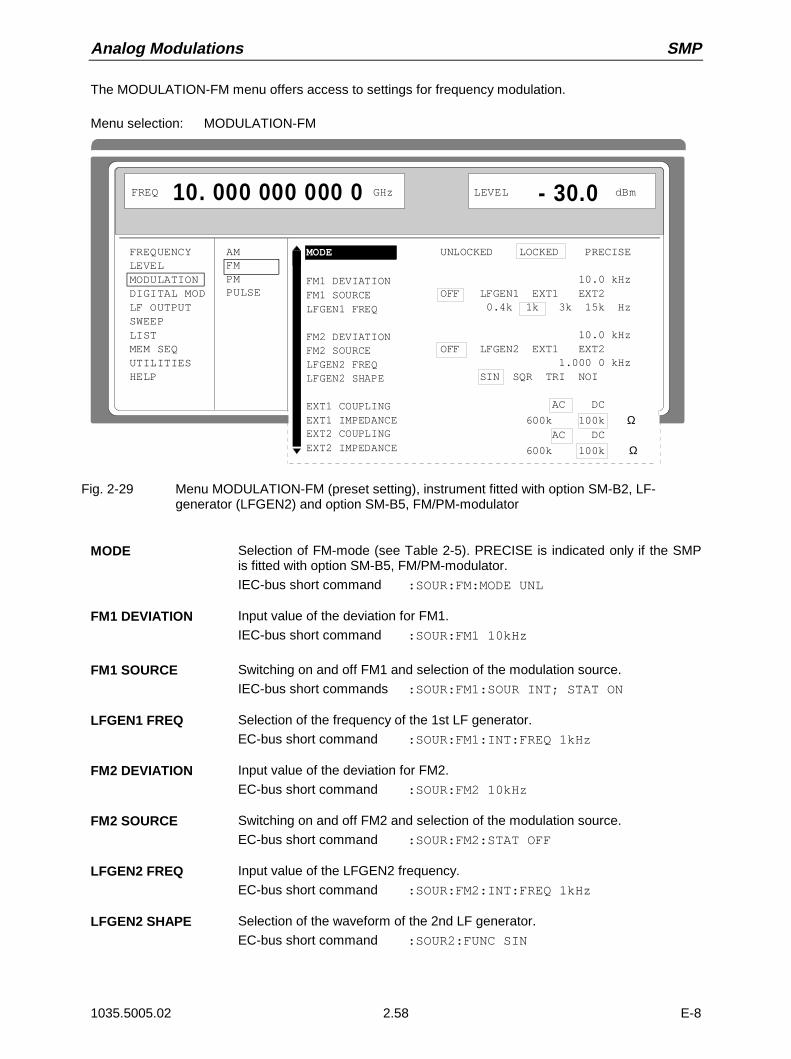
Analog Modulations SMP
1035.5005.02 2.58 E-8
The MODULATION-FM menu offers access to settings for frequency modulation.
Menu selection: MODULATION-FM
FREQUENCYLEVELMODULATIONDIGITAL MODLF OUTPUTSWEEPLISTMEM SEQUTILITIESHELP
AMFMPMPULSE
FREQ 10. 000 000 000 0 GHz LEVEL - 30.0 dBm
UNLOCKED LOCKED PRECISE
10.0 kHz OFF LFGEN1 EXT1 EXT2 0.4k 1k 3k 15k Hz 10.0 kHz OFF LFGEN2 EXT1 EXT2 1.000 0 kHz SIN SQR TRI NOI
AC DC
600k 100k Ω AC DC
600k 100k Ω
MODE
FM1 DEVIATIONFM1 SOURCE LFGEN1 FREQ
FM2 DEVIATIONFM2 SOURCELFGEN2 FREQLFGEN2 SHAPE
EXT1 COUPLINGEXT1 IMPEDANCEEXT2 COUPLINGEXT2 IMPEDANCE
Fig. 2-29 Menu MODULATION-FM (preset setting), instrument fitted with option SM-B2, LF-generator (LFGEN2) and option SM-B5, FM/PM-modulator
MODE Selection of FM-mode (see Table 2-5). PRECISE is indicated only if the SMPis fitted with option SM-B5, FM/PM-modulator.
IEC-bus short command :SOUR:FM:MODE UNL
FM1 DEVIATION Input value of the deviation for FM1.
IEC-bus short command :SOUR:FM1 10kHz
FM1 SOURCE Switching on and off FM1 and selection of the modulation source.
IEC-bus short commands :SOUR:FM1:SOUR INT; STAT ON
LFGEN1 FREQ Selection of the frequency of the 1st LF generator.
EC-bus short command :SOUR:FM1:INT:FREQ 1kHz
FM2 DEVIATION Input value of the deviation for FM2.
EC-bus short command :SOUR:FM2 10kHz
FM2 SOURCE Switching on and off FM2 and selection of the modulation source.
EC-bus short command :SOUR:FM2:STAT OFF
LFGEN2 FREQ Input value of the LFGEN2 frequency.
EC-bus short command :SOUR:FM2:INT:FREQ 1kHz
LFGEN2 SHAPE Selection of the waveform of the 2nd LF generator.
EC-bus short command :SOUR2:FUNC SIN
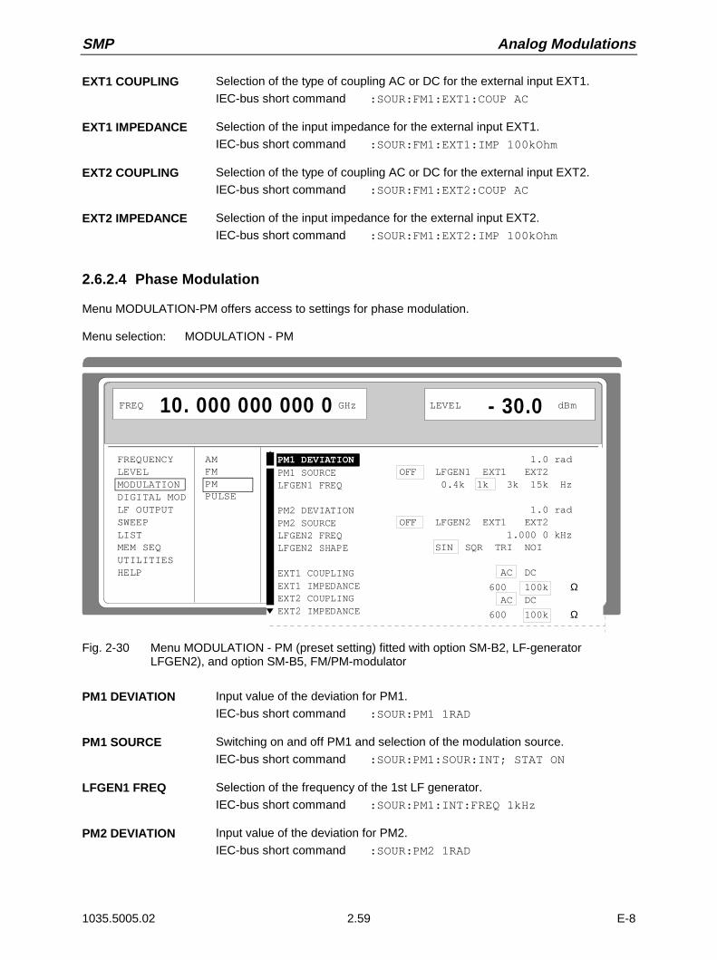
SMP Analog Modulations
1035.5005.02 2.59 E-8
EXT1 COUPLING Selection of the type of coupling AC or DC for the external input EXT1.
IEC-bus short command :SOUR:FM1:EXT1:COUP AC
EXT1 IMPEDANCE Selection of the input impedance for the external input EXT1.
IEC-bus short command :SOUR:FM1:EXT1:IMP 100kOhm
EXT2 COUPLING Selection of the type of coupling AC or DC for the external input EXT2.
IEC-bus short command :SOUR:FM1:EXT2:COUP AC
EXT2 IMPEDANCE Selection of the input impedance for the external input EXT2.
IEC-bus short command :SOUR:FM1:EXT2:IMP 100kOhm
2.6.2.4 Phase Modulation
Menu MODULATION-PM offers access to settings for phase modulation.
Menu selection: MODULATION - PM
FREQUENCYLEVELMODULATIONDIGITAL MODLF OUTPUTSWEEPLISTMEM SEQUTILITIESHELP
AMFMPMPULSE
FREQ 10. 000 000 000 0 GHz LEVEL - 30.0 dBm
1.0 rad OFF LFGEN1 EXT1 EXT2 0.4k 1k 3k 15k Hz 1.0 rad OFF LFGEN2 EXT1 EXT2 1.000 0 kHz SIN SQR TRI NOI
AC DC
600 100k Ω AC DC
600 100k Ω
PM1 DEVIATIONPM1 SOURCE LFGEN1 FREQ
PM2 DEVIATIONPM2 SOURCELFGEN2 FREQLFGEN2 SHAPE
EXT1 COUPLINGEXT1 IMPEDANCEEXT2 COUPLINGEXT2 IMPEDANCE
Fig. 2-30 Menu MODULATION - PM (preset setting) fitted with option SM-B2, LF-generatorLFGEN2), and option SM-B5, FM/PM-modulator
PM1 DEVIATION Input value of the deviation for PM1.
IEC-bus short command :SOUR:PM1 1RAD
PM1 SOURCE Switching on and off PM1 and selection of the modulation source.
IEC-bus short command :SOUR:PM1:SOUR:INT; STAT ON
LFGEN1 FREQ Selection of the frequency of the 1st LF generator.
IEC-bus short command :SOUR:PM1:INT:FREQ 1kHz
PM2 DEVIATION Input value of the deviation for PM2.
IEC-bus short command :SOUR:PM2 1RAD
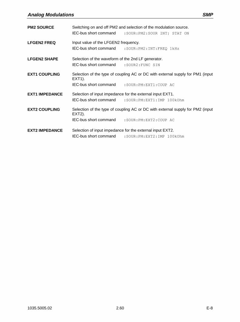
Analog Modulations SMP
1035.5005.02 2.60 E-8
PM2 SOURCE Switching on and off PM2 and selection of the modulation source.
IEC-bus short command :SOUR:PM2:SOUR INT; STAT ON
LFGEN2 FREQ Input value of the LFGEN2 frequency.
IEC-bus short command :SOUR:PM2:INT:FREQ 1kHz
LFGEN2 SHAPE Selection of the waveform of the 2nd LF generator.
IEC-bus short command :SOUR2:FUNC SIN
EXT1 COUPLING Selection of the type of coupling AC or DC with external supply for PM1 (inputEXT1).
IEC-bus short command :SOUR:PM:EXT1:COUP AC
EXT1 IMPEDANCE Selection of input impedance for the external input EXT1.
IEC-bus short command :SOUR:PM:EXT1:IMP 100kOhm
EXT2 COUPLING Selection of the type of coupling AC or DC with external supply for PM2 (inputEXT2).
IEC-bus short command :SOUR:PM:EXT2:COUP AC
EXT2 IMPEDANCE Selection of input impedance for the external input EXT2.
IEC-bus short command :SOUR:PM:EXT2:IMP 100kOhm

SMP Analog Modulations
1035.5005.02 2.61 E-8
2.6.2.5 Pulse Modulation
The pulse modulator can be controlled by an external source as well as by the internal pulse generator.In the case of external control, the external source directly feeds the pulse modulator. The envelope ofthe RF is identical to the control signal. In the case of control by the internal pulse generator, the pulseform of the pulse generator determines the envelope of the RF. Pulse delay, pulse width and period canbe set.
The polarity of the pulse modulation is selectable. With POLARITY = NORM, the RF level is on withHIGH level at modulation input PULSE. With option SMP-B14, the input impedance can be switchedbetween 50 Ω and 10 k Ω. If no option is fitted, it is fixed to 50 Ω.
Note: Option SMP-B12, pulse modulator, improves the measured data in the frequency domainbeyond 2 GHz. Option SMP-B13, pulse modulator 0,01 to 2 GHz, allows pulse modulationin the frequency range between 0,01 and 2 GHz.
2.6.2.5.1 Pulse Generator
As an internal modulation source, the pulse generator (option SMP-B14) offers the possibility to setsingle and double pulses with variable pulse delay, pulse width and period. The pulse generator can betriggered internally or by means of an external signal at the PULSE input. The internal triggering isderived from the reference frequency and hence very stable. In trigger mode EXT, the positive or thenegative edge can be used to trigger the pulse generator.
The pulse generator can also be operated as an independent function without the pulse modulator beingcontrolled if the pulse modulation source SOURCE is switched to OFF or EXT. The pulse can be tappedat the VIDEO output.
SYNC signal
VIDEO signal
RF signal
PERIOD WIDTH PULSE DELAY PULSE DELAY WIDTH
Fig. 2-31 Signal example 1: single pulse, TRIGGER MODE = AUTO
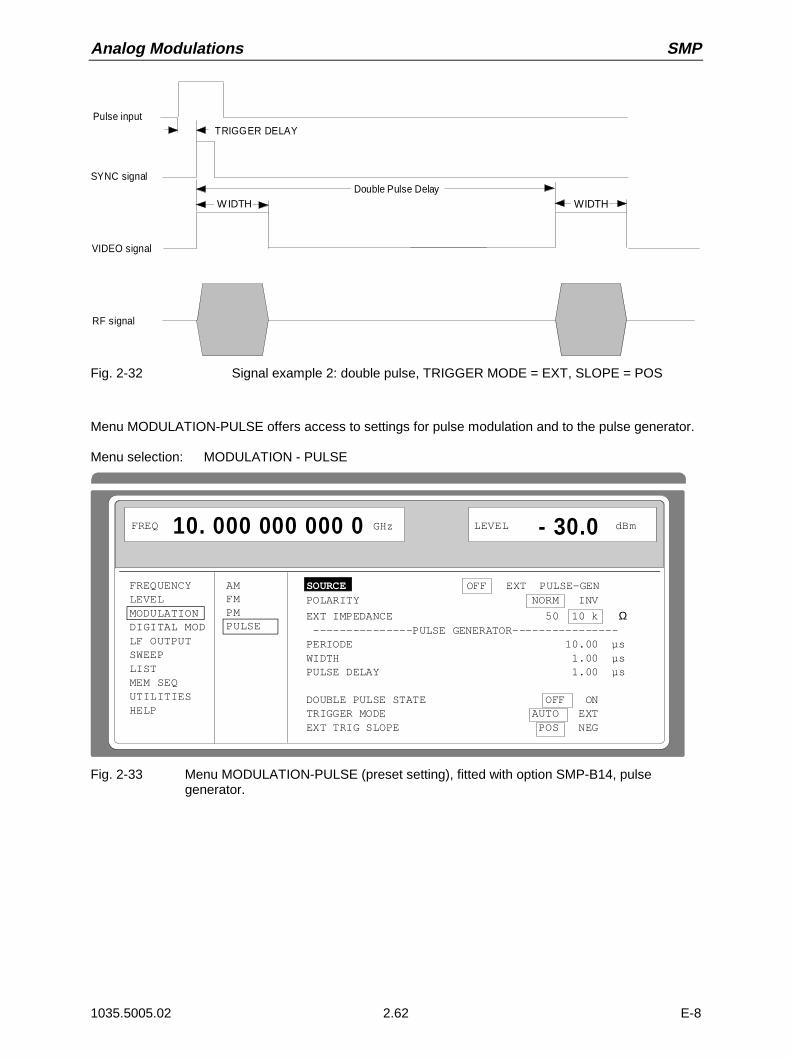
Analog Modulations SMP
1035.5005.02 2.62 E-8
SYNC signal
VIDEO signal
RF signal
WIDTH
TRIGGER DELAY
WIDTH
Pulse input
Double Pulse Delay
Fig. 2-32 Signal example 2: double pulse, TRIGGER MODE = EXT, SLOPE = POS
Menu MODULATION-PULSE offers access to settings for pulse modulation and to the pulse generator.
Menu selection: MODULATION - PULSE
FREQUENCYLEVELMODULATIONDIGITAL MODLF OUTPUTSWEEPLISTMEM SEQUTILITIESHELP
AMFMPMPULSE
FREQ 10. 000 000 000 0 GHz LEVEL - 30.0 dBm
SOURCE OFF EXT PULSE-GENPOLARITY NORM INV
EXT IMPEDANCE 50 10 k Ω ---------------PULSE GENERATOR----------------PERIODE 10.00 µsWIDTH 1.00 µsPULSE DELAY 1.00 µs
DOUBLE PULSE STATE OFF ONTRIGGER MODE AUTO EXTEXT TRIG SLOPE POS NEG
Fig. 2-33 Menu MODULATION-PULSE (preset setting), fitted with option SMP-B14, pulsegenerator.

SMP Analog Modulations
1035.5005.02 2.63 E-8
SOURCE Selection of the modulation source.
IEC-bus short command :SOUR:PULM:SOUR INT; STAT ON
POLARITY Selection of the polarity of the modulation
NORM The RF signal is on during high level.
INV The RF signal is suppressed during high level.
IEC-bus short command :SOUR:PULM:POL NORM
EXT IMPEDANCE Selection of the input resistance 50 Ω or 10 kΩ.
IEC-bus short command :SOUR:PULM:EXT:IMP 50
PERIOD Input value of the period.
IEC-bus short command :SOUR:PULS:PER 10us
WIDTH Input value of the pulse width.
IEC-bus short command :SOUR:PULS:WIDT 1us
PULSE DELAY Input value of the single-pulse delay. Is only displayed if DOUBLE PULSESTATE is set to be OFF.
IEC-bus short command :SOUR:PULS:DEL 1us
DOUBLE PULSE DELAY Input value of the double-pulse delay.
IEC-bus short command :SOUR:PULS:DOUB:DEL 1us
DOUBLE PULSE STATE Switching on/off the double pulses.
ON Double pulse is switched on
OFF Single pulse
IEC-bus short command :SOUR:PULS:DOUB ON
TRIGGER MODE Selection of the trigger mode.
AUTO Period as entered under PERIOD.
EXT Period is determined by the external signal at the PULSE input.
IEC-bus short command :TRIG:PULS:SOUR AUTO
EXT TRIG SLOPE Selection of the active edge of the external trigger signal.
POS Pulse generator triggers on positive edge of the external signal.
NEG Pulse generator triggers on negative edge of the external signal.
IEC-bus short command :TRIG:PULS:SLOP POS

Sweep SMP
1035.5005.02 E-82.64
2.6.3 Digital Modulation ASK and FSK
Menu DIGITAL MOD-ASK offers access to settings for ASK modulation.
Menu selection: DIGITAL MOD-ASK
FREQUENCYLEVELMODULATIONDIGITAL MODLF OUTPUTSWEEPLISTMEM SEQUTILITIESHELP
ASKFSK
SOURCE
DEPTH
EXT1 IMPEDANCEPOLARITY
FREQ 10.000 000 000 0 GHz LEVEL - 30.0 dBm
OFF EXT1 30.0 %
600 100k Ω NORM INV
Fig. 2-34 Menu DIGITAL MOD-ASK (preset setting)
SOURCE Selection of the modulation source ASK (Amplitude Shift Keying).
IEC-bus short command :SOUR:DM:TYPE ASK; SOUR EXT; STAT ON
DEPTH Input value of the deviation for ASK.
IEC-bus short command :SOUR:DM:ASK:DEPT 30PCT
EXT1 IMPEDANCE Selection of the input impedance of external input EXT1.
IEC-bus short command :SOUR:DM:EXT:IMP 100kOHM
POLARITY Selection of polarity of modulation
IEC-bus short command :SOUR:DM:ASK:POL NORM

SMP Sweep
1035.5005.02 E-82.65
Menu DIGITAL MOD-FSK offers access to settings for FSK modulation.
Menu selection: DIGITAL MOD-FSK
FREQUENCYLEVELMODULATIONDIGITAL MODLF OUTPUTSWEEPLISTMEM SEQUTILITIESHELP
ASKFSK
MODESOURCE
DEVIATION
EXT1 IMPEDANCEPOLARITY
FREQ 10.000 000 000 0 GHz LEVEL - 30.0 dBm
UNLOCKED LOCKED PRECISE OFF EXT1 10.000 kHz
600 100k Ω NORM INVERTED
Fig. 2-35 Menu DIGITAL MOD - FSK (preset setting), fittet with option SM-B5, FMφM modulator
MODE Selection of the operating mode of the frequency modulation(cf. Section " Frequency Modulation").
IEC-bus short command :SOUR:DM:FSK:MODE LOCK
SOURCE Selection of the modulation source FSK (Frequency Shift Keying).
IEC-bus short command :SOUR:DM:TYPE FSK;SOUR EXT;STAT ON
DEVIATION Input value of the deviation for FSK
IEC-bus short command :SOUR:DM:FSK:DEV 10kHz
EXT1 IMPEDANCE Selection of the input impedance of external input EXT1.
IEC-bus short command :SOUR:DM:EXT:IMP 100kOhm
POLARITY Selection of polarity of modulation
IEC-bus short command :SOUR:DM:FSK:POL NORM
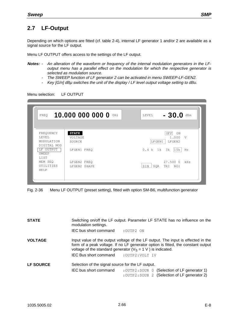
Sweep SMP
1035.5005.02 E-82.66
2.7 LF-Output
Depending on which options are fitted (cf. table 2-4), internal LF generator 1 and/or 2 are available as asignal source for the LF output.
Menu LF OUTPUT offers access to the settings of the LF output.
Notes: - An alteration of the waveform or frequency of the internal modulation generators in the LF-output menu has a parallel effect on the modulation for which the respective generator isselected as modulation source.
- The SWEEP function of LF generator 2 can be activated in menu SWEEP-LF-GEN2.- Key [G/n] dBµ switches the unit of the display / LF level output voltage setting to dBu.
Menu selection: LF OUTPUT
FREQUENCYLEVELMODULATIONDIGITAL MODLF OUTPUTSWEEPLISTMEM SEQUTILITIESHELP
STATE OFF ONVOLTAGE 1.000 VSOURCE LFGEN1 LFGEN2
LFGEN1 FREQ 0.4 k 1k 3k 15k Hz
LFGEN2 FREQ 27.500 0 kHzLFGEN2 SHAPE SIN SQR TRI NOI
FREQ 10.000 000 000 0 GHz LEVEL - 30.0 dBm
Fig. 2-36 Menu LF OUTPUT (preset setting), fitted with option SM-B6, multifunction generator
STATE Switching on/off the LF output. Parameter LF STATE has no influence on themodulation settings.
IEC bus short command :OUTP2 ON
VOLTAGE Input value of the output voltage of the LF output. The input is effected in theform of a peak voltage. If no LF generator option is fitted, the constant outputvoltage of the standard generator (VS = 1 V ) is indicated.
IEC Bus short command :OUTP2:VOLT 1V
LF SOURCE Selection of the signal source for the LF output.
IEC bus short command :OUTP2:SOUR 0 (Selection of LF generator 1):OUTP2:SOUR 2 (Selection of LF generator 2)
SMP Sweep
1035.5005.02 E-82.67
LFGEN1 FREQ Input value of the frequency of internal modulation generator 1.
IEC bus short command :SOUR0:FREQ 15kHz
LFGEN1 SHAPE Input value of the signal shape for modulation generator 1. The signal shape ofmodulation generator 1 can only be set if two modulation generator options arefitted.
IEC bus short command :SOUR0:FUNC SIN
LFGEN2 FREQ Input value of the frequency of internal modulation generator 2. This parameteris only displayed if a modulation generator option is fitted.
IEC bus short command :SOUR2:FREQ 27.5kHz
LFGEN2 SHAPE Input value of the signal shape of modulation generator 2. This parameter isonly displayed if a modulation generator option is fitted.
IEC bus short command :SOUR2:FUNC SIN
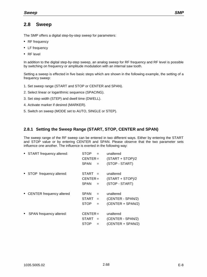
Sweep SMP
1035.5005.02 E-82.68
2.8 Sweep
The SMP offers a digital step-by-step sweep for parameters:
• RF frequency
• LF frequency
• RF level
In addition to the digital step-by-step sweep, an analog sweep for RF frequency and RF level is possibleby switching on frequency or amplitude modulation with an internal saw tooth.
Setting a sweep is effected in five basic steps which are shown in the following example, the setting of afrequency sweep:
1. Set sweep range (START and STOP or CENTER and SPAN).
2. Select linear or logarithmic sequence (SPACING).
3. Set step width (STEP) and dwell time (DWELL).
4. Activate marker if desired (MARKER).
5. Switch on sweep (MODE set to AUTO, SINGLE or STEP).
2.8.1 Setting the Sweep Range (START, STOP, CENTER and SPAN)
The sweep range of the RF sweep can be entered in two different ways. Either by entering the STARTand STOP value or by entering CENTER and SPAN. Please observe that the two parameter setsinfluence one another. The influence is exerted in the following way:
• START frequency altered: STOP = unaltered
CENTER = (START + STOP)/2
SPAN = (STOP - START)
• STOP frequency altered: START = unaltered
CENTER = (START + STOP)/2
SPAN = (STOP - START)
• CENTER frequency altered SPAN = unaltered
START = (CENTER - SPAN/2)
STOP = (CENTER + SPAN/2)
• SPAN frequency altered: CENTER = unaltered
START = (CENTER - SPAN/2)
STOP = (CENTER + SPAN/2)

SMP Sweep
1035.5005.02 E-82.69
2.8.2 Selecting the Sweep Run (SPACING LIN, LOG)
The sweep run, linear or logarithmic, can be selected using SPACING. For the RF and LF sweep, alinear or logarithmic run is possible. For level sweep, only the logarithmic run is possible.
With the logarithmic sweep, step width STEP is equal to a constant fraction of the present setting. Thelogarithmic step width is entered in unit % with RF or LF sweep, in unit dB with level sweep.
2.8.3 Operating Modes (MODE)
The following sweep operating modes are available:
AUTO Sweep from the starting point to the stop point, with automatic restart at the startingpoint. If another sweep operating mode was activated prior to the AUTO operatingmode, continuation is made from the current sweep setting (cf. Fig. 2-37).
IEC bus short commands:
RF sweep: LF sweep: Level sweep:
SOUR:FREQ:MODE SWE SOUR2:FREQ:MODE SWE SOUR:POW:MODE SWESOUR:SWE:MODE AUTO SOUR2:SWE:MODE AUTO SOUR:SWE:POW:MODE AUTOTRIG:SOUR AUTO TRIG2:SOUR AUTO TRIG:SOUR AUTO
SINGLE Single run from the starting point to the stop point. If SINGLE is selected, the run isnot started yet. Function EXECUTE SINGLE SWEEP to be executed, which canbe used to start the run, is displayed below the MODE line (cf. Fig. 2-38).
IEC bus short commands:
RF sweep: LF sweep: Level sweep:
SOUR:FREQ:MODE SWE SOUR2:FREQ:MODE SWE SOUR:POW:MODE SWESOUR:SWE:MODE AUTO SOUR2:SWE:MODE AUTO SOUR:SWE:POW:MODE AUTOTRIG:SOUR SING TRIG2:SOUR SING TRIG:SOUR SING
STEP Step-by-step, manual run within the sweep limits. Activating STEP stops a runningsweep and the cursor wraps to the indication value of CURRENT. The sweep runcan now be controlled upwards or downwards in discrete steps using the rotary knobor the numeric keys.
IEC bus short commands:
RF sweep: LF sweep: Level sweep:
SOUR:FREQ:MODE SWE SOUR2:FREQ:MODE SWE SOUR:POW:MODE SWESOUR:SWE:MODE STEP SOUR2:SWE:MODE STEP SOUR:SWE:POW:MODE STEPTRIG:SOUR SING TRIG2:SOUR SING TRIG:SOUR SING
EXT-SINGLE Single run from the starting point to the stop point as in the case of SINGLE, buttriggered by an external trigger signal.
IEC-bus short commands:
RF sweep: LF sweep: Level sweep:
SOUR:FREQ:MODE SWE SOUR2:FREQ:MODE SWE SOUR:POW:MODE SWESOUR:SWE:MODE AUTO SOUR2:SWE:MODE AUTO SOUR:SWE:POW:MODE AUTOTRIG:SOUR EXT TRIG2:SOUR EXT TRIG:SOUR EXT

Sweep SMP
1035.5005.02 E-82.70
EXT-STEP Step-by-step run by means of the external trigger signal. Each trigger event triggersa single step.
IEC-bus short commands:
RF sweep: LF sweep: Level sweep:SOUR:FREQ:MODE SWE SOUR2:FREQ:MODE SWE SOUR:POW:MODE SWESOUR:SWE:MODE STEP SOUR2:SWE:MODE STEP SOUR:SWE:POW:MODE STEPTRIG:SOUR EXT TRIG2:SOUR EXT TRIG:SOUR EXT
OFF The sweep operating mode is switched off.
IEC-bus short commands:
RF sweep: LF sweep: Level sweep:SOUR:FREQ:MODE CW SOUR2:FREQ:MODE CW SOUR:POW:MODE CW
2.8.4 Trigger Inputs
TRIGGER An external signal at the rear input triggers the sweep in the EXT-SINGLE and EXT-STEP operating modes. The polarity of the active trigger edge can be set in menuUTILITIES - AUX I/O EXT TRIG SLOPE.
STOP An external signal at the rear input stops the sweep in all operating modes. Thepolarity of the signal can be set in the UTILITIES-AUX I/O-STOP POLARITY menu.
2.8.5 Sweep Outputs
Outputs X-AXIS, V/GHz, BLANK and MARKER are available at the rear of the instrument to control andtrigger oscilloscopes or XY recorders.
X-AXIS With sweep switched on, this output supplies a voltage ramp of 0 to 10 V for the X-deflection of an oscilloscope or an XY recorder.
V/GHZ (for equipment with option SMP-B18). This output supplies a voltage proportional tothe current frequency. The slope, either 0.5 V/GHz or 1 V/GHz, corresponds to arange from 5 mV to 10 V and 10 mV to 20 V for 10 MHz to 20 GHz. A slope of5 V/GHz is available above 20 GHz (SMP03/04). The slope can be set underUTILITIES AUX I/O V/GHz. The voltage is always available even with sweepswitched off.
BLANK This output supplies a signal (0V/5V) to trigger and blank an oscilloscope or for thePEN LIFT control of an XY recorder. The polarity and the period of the signal can beset under UTILITIES - AUX I/O - BLANK POLARITY and - BLANK TIME.
MARKER This output becomes active when the sweep run has reached the mark. TheMARKER signal can be used for the brightness control of an oscilloscope. Up tothree marks can be set in order to mark certain positions in the sweep run. Thepolarity of the signal can be set in menu UTILITIES - AUX I/O - MARKERPOLARITY. The period of the active signal is equal to the dwell time (DWELL) of astep.

SMP Sweep
1035.5005.02 E-82.71
Signal examples
10 V
0 V
X-AXIS
20 V
10 V
0 V
V/GHz
0 V
5 V
5 V
0 V
BLANK
MARKER
Fig. 2-37 Signal example sweep 0 to 20 GHz: MODE = AUTO,V/GHz = 1V/GHz, BLANK TIME = NORMAL
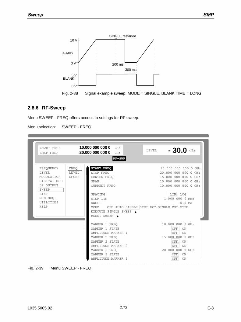
Sweep SMP
1035.5005.02 E-82.72
10 V
0 V
X-AXIS
BLANK5 V
0 V
200 ms
300 ms
SINGLE restarted
Fig. 2-38 Signal example sweep: MODE = SINGLE, BLANK TIME = LONG
2.8.6 RF-Sweep
Menu SWEEP - FREQ offers access to settings for RF sweep.
Menu selection: SWEEP - FREQ
FREQUENCYLEVELMODULATIONDIGITAL MODLF OUTPUTSWEEPLISTMEM SEQUTILITIESHELP
FREQLEVELLFGEN
LEVEL dBm
START FREQ 10.000 000 000 0 GHzSTOP FREQ 20.000 000 000 0 GHzCENTER FREQ 15.000 000 000 0 GHzSPAN 10.000 000 000 0 GHzCURRENT FREQ 10.000 000 000 0 GHz
SPACING LIN LOGSTEP LIN 1.000 000 0 MHzDWELL 15.0 msMODE OFF AUTO SINGLE STEP EXT-SINGLE EXT-STEPEXECUTE SINGLE SWEEPRESET SWEEP
MARKER 1 FREQ 10.000 000 0 GHzMARKER 1 STATE OFF ONAMPLITUDE MARKER 1 OFF ONMARKER 2 FREQ 15.000 000 0 GHzMARKER 2 STATE OFF ONAMPLITUDE MARKER 2 OFF ONMARKER 3 FREQ 20.000 000 0 GHzMARKER 3 STATE OFF ONAMPLITUDE MARKER 3 OFF ON
- 30.0START FREQ 10.000 000 000 0 GHzSTOP FREQ 20.000 000 000 0 GHz
RF-SWP
Fig. 2-39 Menu SWEEP - FREQ

SMP Sweep
1035.5005.02 E-82.73
START FREQ Input value of the starting frequency.
IEC bus short command :SOUR:FREQ:STAR 10GHz
STOP FREQ Input value of the stop frequency.
IEC bus short command :SOUR:FREQ:STOP 20GHz
CENTER FREQ Input value of the center frequency.
IEC bus short command :SOUR:FREQ:CENT 15GHz
SPAN Input value of the span.
IEC bus short command :SOUR:FREQ:SPAN 10GHz
CURRENT FREQ Indication of the current frequency value.Operating mode STEP: Input value of the frequency.
SPACING Input value of the dwell time per step.
IEC bus short command :SOUR:SWE:SPAC LIN
STEP LIN (LOG) Input value of the step width. Depending on whether SPACING LIN or LOGis selected, STEP LIN or STEP LOG is displayed.
IEC bus short command :SOUR:SWE:STEP:LIN 1MHz
DWELL Input value of the dwell time per step.
IEC bus short command :SOUR:SWE:DWEL 15ms
MODE Selection of the sweep operating mode.
IEC bus short commands :SOUR:FREQ:MODE SWE;
:SOUR:SWE:MODE AUTO;
:TRIG:SOUR SING
EXECUTE SINGLESWEEP
Starts a single sweep run. This action to be executed is only indicated and isonly effective if MODE SINGLE has been selected.
IEC bus short command :TRIG
RESET SWEEP Sets the starting frequency.
IEC bus short command :ABOR
MARKER 1 FREQMARKER 2 FREQMARKER 3 FREQ
Input value of the frequency for the marker selected
IEC bus short command :SOUR:MARK1:FREQ 10GMHz
MARKER 1 STATEMARKER 2 STATEMARKER 3 STATE
Switching on/off the marker selected
IEC bus short command :SOUR:MARK1 OFF
AMPLITUDE MARKER1AMPLITUDE MARKER 2AMPLITUDE MARKER 3
Switching on/off the amplitude marker selected
OFF Input value of the frequency for the marker selected
ON Amplitude marker is switched on. On reaching the mark the outputlevel is reduced by 1 dB.
IEC bus short command :SOUR:MARK1:AMPL OFF
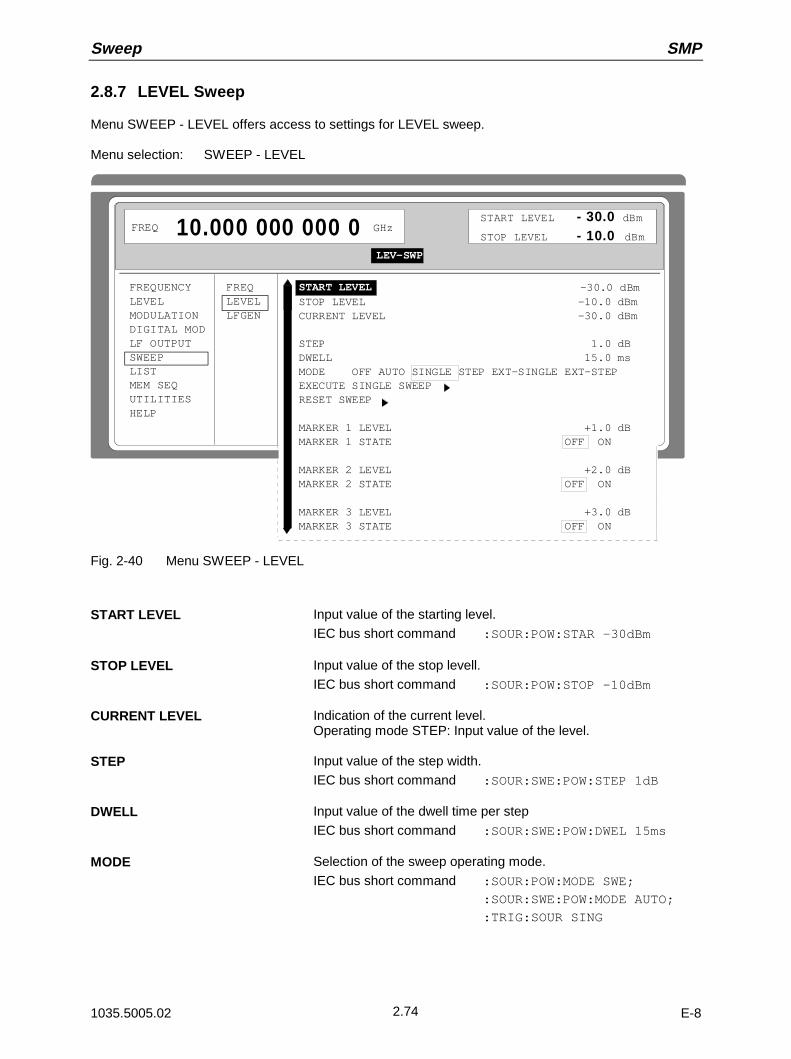
Sweep SMP
1035.5005.02 E-82.74
2.8.7 LEVEL Sweep
Menu SWEEP - LEVEL offers access to settings for LEVEL sweep.
Menu selection: SWEEP - LEVEL
FREQUENCYLEVELMODULATIONDIGITAL MODLF OUTPUTSWEEPLISTMEM SEQUTILITIESHELP
FREQLEVELLFGEN
FREQ 10.000 000 000 0 GHz
START LEVEL -30.0 dBmSTOP LEVEL -10.0 dBmCURRENT LEVEL -30.0 dBm
STEP 1.0 dBDWELL 15.0 msMODE OFF AUTO SINGLE STEP EXT-SINGLE EXT-STEPEXECUTE SINGLE SWEEP RESET SWEEP
MARKER 1 LEVEL +1.0 dBMARKER 1 STATE OFF ON
MARKER 2 LEVEL +2.0 dBMARKER 2 STATE OFF ON
MARKER 3 LEVEL +3.0 dBMARKER 3 STATE OFF ON
START LEVEL - 30.0 dBm
STOP LEVEL - 10.0 dBmLEV-SWP
Fig. 2-40 Menu SWEEP - LEVEL
START LEVEL Input value of the starting level.
IEC bus short command :SOUR:POW:STAR -30dBm
STOP LEVEL Input value of the stop levell.
IEC bus short command :SOUR:POW:STOP -10dBm
CURRENT LEVEL Indication of the current level.Operating mode STEP: Input value of the level.
STEP Input value of the step width.
IEC bus short command :SOUR:SWE:POW:STEP 1dB
DWELL Input value of the dwell time per step
IEC bus short command :SOUR:SWE:POW:DWEL 15ms
MODE Selection of the sweep operating mode.
IEC bus short command :SOUR:POW:MODE SWE;
:SOUR:SWE:POW:MODE AUTO;
:TRIG:SOUR SING
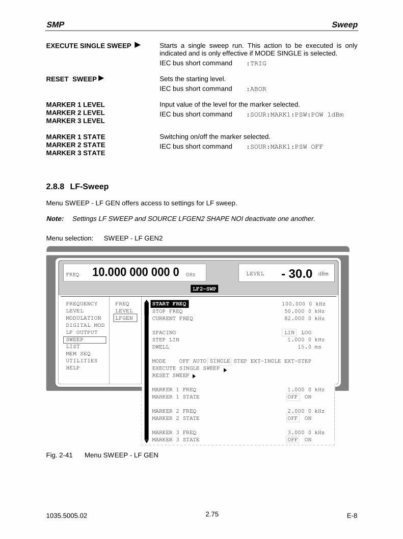
SMP Sweep
1035.5005.02 E-82.75
EXECUTE SINGLE SWEEP Starts a single sweep run. This action to be executed is onlyindicated and is only effective if MODE SINGLE is selected.
IEC bus short command :TRIG
RESET SWEEP Sets the starting level.
IEC bus short command :ABOR
MARKER 1 LEVELMARKER 2 LEVELMARKER 3 LEVEL
Input value of the level for the marker selected.
IEC bus short command :SOUR:MARK1:PSW:POW 1dBm
MARKER 1 STATEMARKER 2 STATEMARKER 3 STATE
Switching on/off the marker selected.
IEC bus short command :SOUR:MARK1:PSW OFF
2.8.8 LF-Sweep
Menu SWEEP - LF GEN offers access to settings for LF sweep.
Note: Settings LF SWEEP and SOURCE LFGEN2 SHAPE NOI deactivate one another.
Menu selection: SWEEP - LF GEN2
FREQUENCYLEVELMODULATIONDIGITAL MODLF OUTPUTSWEEPLISTMEM SEQUTILITIESHELP
FREQLEVELLFGEN
FREQ 10.000 000 000 0 GHz
LEVEL dBm
START FREQ 100.000 0 kHzSTOP FREQ 50.000 0 kHzCURRENT FREQ 82.000 0 kHz
SPACING LIN LOGSTEP LIN 1.000 0 kHzDWELL 15.0 ms
MODE OFF AUTO SINGLE STEP EXT-INGLE EXT-STEPEXECUTE SINGLE SWEEPRESET SWEEP
MARKER 1 FREQ 1.000 0 kHzMARKER 1 STATE OFF ON
MARKER 2 FREQ 2.000 0 kHzMARKER 2 STATE OFF ON
MARKER 3 FREQ 3.000 0 kHzMARKER 3 STATE OFF ON
- 30.0LF2-SWP
Fig. 2-41 Menu SWEEP - LF GEN

Sweep SMP
1035.5005.02 E-82.76
START FREQ Input value of the starting frequency.
IEC bus short command :SOUR2:FREQ:STAR 100kHz
STOP FREQ Input value of the stop frequency.
IEC bus short command :SOUR2:FREQ:STOP 50kHz
CURRENT FREQ Indication of the current frequency value.Operating mode STEP: Input value of the frequency.
STEP Input value of the step width.
IEC bus short command :SOUR2:SWE:STEP:LIN 1kHz
DWELL Input value of the dwell time per step.
IEC bus short command :SOUR2:SWE:DWEL 15ms
SPACING Selection of the sweep run, linear or logarithmic.
IEC bus short command :SOUR2:SWE:SPAC LIN
MODE Selection of the sweep operating mode.
IEC bus short command :SOUR2:FREQ:MODE SWE
:SOUR2:SWE:MODE AUTO
:TRIG2:SOUR SING
EXECUTE SINGLE SWEEP Starts a single sweep run. This action to be executed is only indicatedand is only effective if MODE SINGLE is selected.
IEC bus short command :TRIG
RESET SWEEP Sets the starting frequency.
IEC bus short command :ABOR
MARKER 1 FREQMARKER 2 FREQMARKER 3 FREQ
Input value of the frequency for the marker selected.
IEC bus short command :SOUR2:MARK1:FREQ 100kHz
MARKER 1 STATEMARKER 2 STATEMARKER 3 STATE
Switching on/off the marker selected.
IEC bus short command :SOUR2:MARK1 OFF
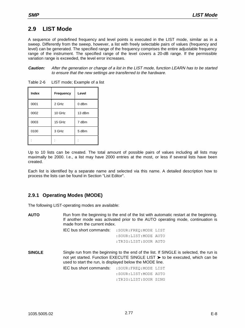
SMP LIST Mode
1035.5005.02 E-82.77
2.9 LIST Mode
A sequence of predefined frequency and level points is executed in the LIST mode, similar as in asweep. Differently from the sweep, however, a list with freely selectable pairs of values (frequency andlevel) can be generated. The specified range of the frequency comprises the entire adjustable frequencyrange of the instrument. The specified range of the level covers a 20-dB range. If the permissiblevariation range is exceeded, the level error increases.
Caution: After the generation or change of a list in the LIST mode, function LEARN has to be startedto ensure that the new settings are transferred to the hardware.
Table 2-6 LIST mode; Example of a list
Index Frequency Level
0001 2 GHz 0 dBm
0002 10 GHz 13 dBm
0003 15 GHz 7 dBm
0100 3 GHz 5 dBm
: : :
Up to 10 lists can be created. The total amount of possible pairs of values including all lists maymaximally be 2000. I.e., a list may have 2000 entries at the most, or less if several lists have beencreated.
Each list is identified by a separate name and selected via this name. A detailed description how toprocess the lists can be found in Section "List Editor".
2.9.1 Operating Modes (MODE)
The following LIST-operating modes are available:
AUTO Run from the beginning to the end of the list with automatic restart at the beginning.If another mode was activated prior to the AUTO operating mode, continuation ismade from the current index.
IEC bus short commands: :SOUR:FREQ:MODE LIST
:SOUR:LIST:MODE AUTO
:TRIG:LIST:SOUR AUTO
SINGLE Single run from the beginning to the end of the list. If SINGLE is selected, the run isnot yet started. Function EXECUTE SINGLE LIST to be executed, which can beused to start the run, is displayed below the MODE line.
IEC bus short commands: :SOUR:FREQ:MODE LIST
:SOUR:LIST:MODE AUTO
:TRIG:LIST:SOUR SING
LIST Mode SMP
1035.5005.02 E-82.78
STEP Step-by-step manual processing of the list. Activating STEP stops a list running andthe cursor wraps to the indication value of CURRENT INDEX. The list can now becontrolled upwards or downwards in discrete steps using the rotary knob or thenumeric keys.
IEC bus short commands: :SOUR:FREQ:MODE LIST
:SOUR:LIST:MODE STEP
:TRIG:LIST:SOUR SING
EXT-SINGLE Single run from the beginning to the end of the list as with SINGLE, but triggered byan external trigger signal.
IEC bus short commands: :SOUR:FREQ:MODE LIST;
:SOUR:LIST:MODE AUTO
:TRIG:LIST:SOUR EXT
EXT-STEP Step-by-step run by means of the external trigger signal. Each trigger event triggersa single step.
IEC bus short commands: :SOUR:FREQ:MODE LIST
:SOUR:LIST:MODE STEP
:TRIG:LIST:SOUR EXT
OFF Operating mode LIST is switched off.
IEC bus short command: :SOUR:FREQ:MODE CW
2.9.2 Inputs/Outputs
TRIGGER input and BLANK output are available at the rear of the instrument for synchronization withother instruments.
TRIGGER An external signal at this input triggers the LIST mode in operating modesEXT-SINGLE and EXT-STEP. The polarity of the active trigger edge can beset in the UTILITIES - AUX I/O - EXT TRIG SLOPE menu.
BLANK This output supplies a signal (0 V/5 V) to blank the settling process by meansof pulse modulation or AM. The signal can also be used to synchronize otherinstruments. The polarity of the signal can be set in the UTILITIES - AUX I/O -BLANK POLARITY menu.
MARKER At the first step of the LIST mode, this output provides an approx. 200 µstrigger signal immediately after blanking. At small DWELL times, this signalcan be used for an accurate synchronization to trigger other devices andshows the first stable output frequency. The delay to the fed-in signal at theTRIGGER input for EXT-SINGLE or EXT-STEP is 1.5 to 2 ms and has a jitterof 0.5 ms.
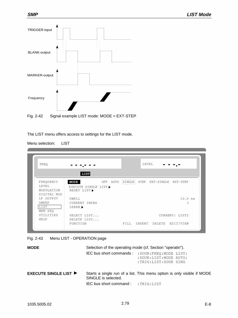
SMP LIST Mode
1035.5005.02 E-82.79
TRIGGER input
BLANK-output
MARKER-output
Frequency
Fig. 2-42 Signal example LIST mode: MODE = EXT-STEP
The LIST menu offers access to settings for the LIST mode.
Menu selection: LIST
FREQUENCYLEVELMODULATIONDIGITAL MODLF OUTPUTSWEEPLISTMEM SEQUTILITIESHELP
LEVEL - - -.- - - -.- - -
MODE OFF AUTO SINGLE STEP EXT-SINGLE EXT-STEP
RESET LIST
DWELL 10.0 msCURRENT INDEX 1LEARN
SELECT LIST... CURRENT: LIST2DELETE LIST...FUNCTION FILL INSERT DELETE EDIT/VIEW
FREQ
LIST
EXECUTE SINGLE LIST
Fig. 2-43 Menu LIST - OPERATION page
MODE Selection of the operating mode (cf. Section "operatin").
IEC bus short commands : :SOUR:FREQ:MODE LIST;:SOUR:LIST:MODE AUTO;:TRIG:LIST:SOUR SING
EXECUTE SINGLE LIST Starts a single run of a list. This menu option is only visible if MODESINGLE is selected.
IEC bus short command : :TRIG:LIST
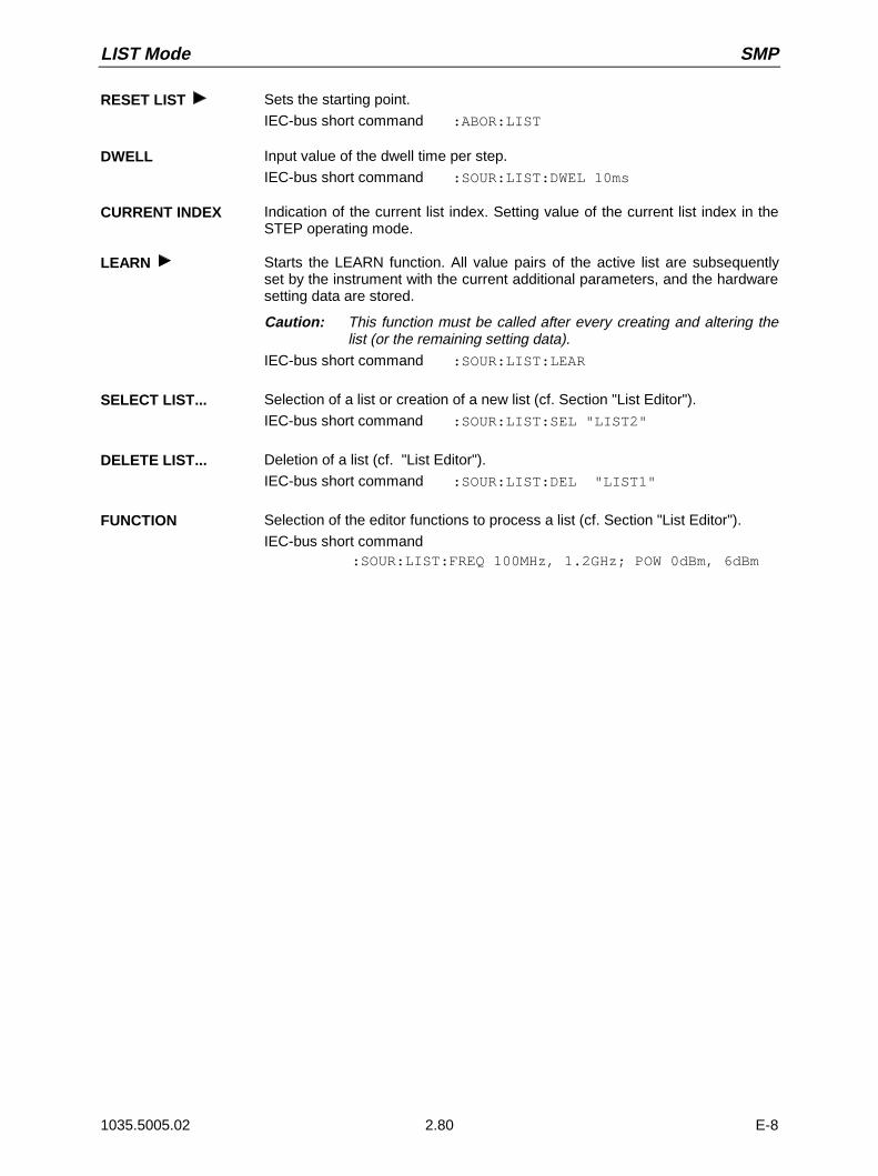
LIST Mode SMP
1035.5005.02 2.80 E-8
RESET LIST Sets the starting point.
IEC-bus short command :ABOR:LIST
DWELL Input value of the dwell time per step.
IEC-bus short command :SOUR:LIST:DWEL 10ms
CURRENT INDEX Indication of the current list index. Setting value of the current list index in theSTEP operating mode.
LEARN Starts the LEARN function. All value pairs of the active list are subsequentlyset by the instrument with the current additional parameters, and the hardwaresetting data are stored.
Caution: This function must be called after every creating and altering thelist (or the remaining setting data).
IEC-bus short command :SOUR:LIST:LEAR
SELECT LIST... Selection of a list or creation of a new list (cf. Section "List Editor").
IEC-bus short command :SOUR:LIST:SEL "LIST2"
DELETE LIST... Deletion of a list (cf. "List Editor").
IEC-bus short command :SOUR:LIST:DEL "LIST1"
FUNCTION Selection of the editor functions to process a list (cf. Section "List Editor").
IEC-bus short command:SOUR:LIST:FREQ 100MHz, 1.2GHz; POW 0dBm, 6dBm

SMP LIST Mode
1035.5005.02 2.81 E-8
The second page of the LIST menu, the EDIT page is automatically activated if one of the editorfunctions of line FUNCTION is selected. The list which is displayed as CURRENT LIST in the SELECTLIST line is shown.
FREQUENCYLEVELMODULATIONDIGITAL MODLF OUTPUTSWEEPLISTMEM SEQUTILITIESHELP
FREQ 10.000 000 000 0 GHz LEVEL - 30.0 dBm
SELECT LIST... CURRENT: LIST2FUNCTION FILL-LIST INSERT DELETE EDIT/VIEW-INDEX- FREE 2041 - LEN 2055 FREQ LEVEL 0001 2.000 000 0 GHz 0.0 dBm 0002 10.000 000 0 GHz 13.0 dBm 0003 15.000 000 0 GHz 7.0 dBm 0004 3.000 000 0 GHz 5.0 dBm 0005 5.000 000 0 GHz 3.0 dBm 0006 3.000 000 0 GHz 4.0 dBm 0007 4.000 000 0 GHz 7.0 dBm 0008 5.000 000 0 GHz 7.0 dBm
Fig. 2-44 Menu List - EDIT page
INDEX Index of the list.
FREE Indication of the list entries still vacant.
LENGTH Length of the current list.
FREQ Parameter: Frequency.
LEVEL Parameter: Level; specified range 20 dB.
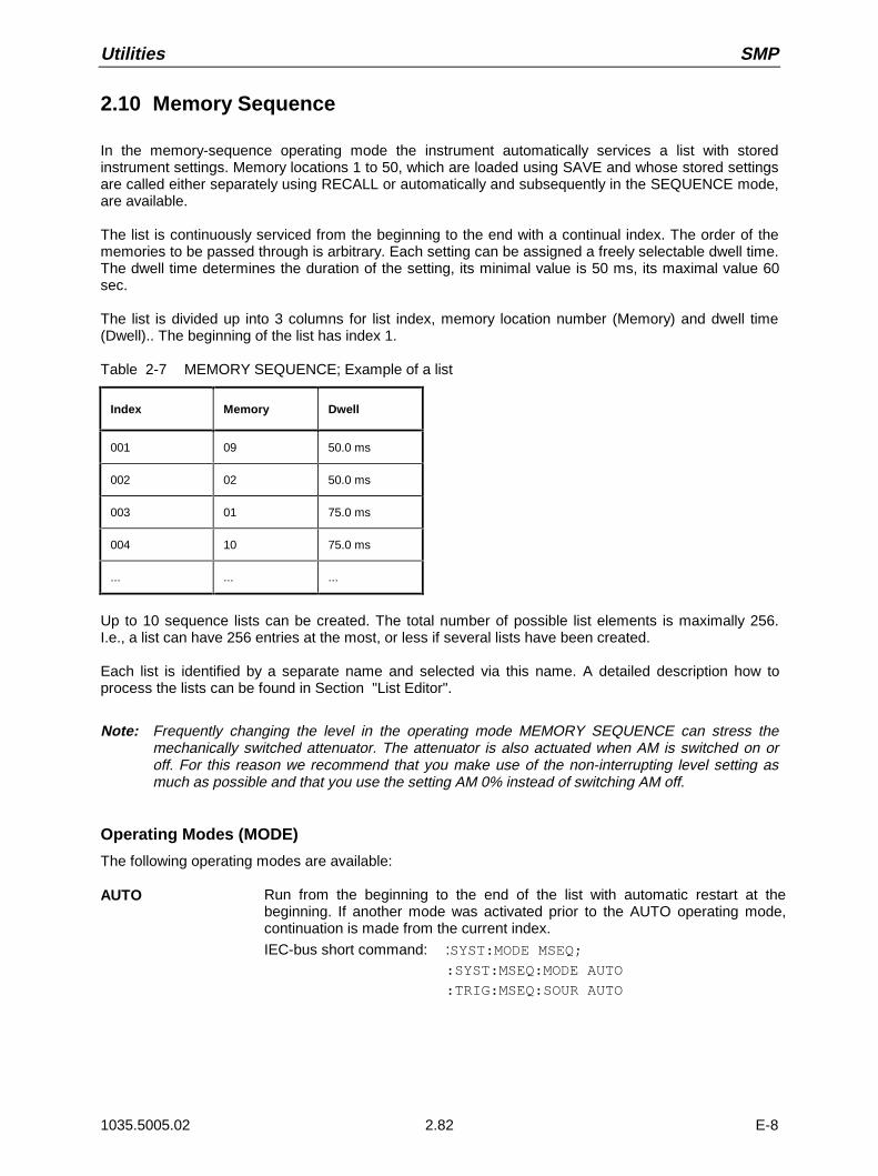
Utilities SMP
1035.5005.02 2.82 E-8
2.10 Memory Sequence
In the memory-sequence operating mode the instrument automatically services a list with storedinstrument settings. Memory locations 1 to 50, which are loaded using SAVE and whose stored settingsare called either separately using RECALL or automatically and subsequently in the SEQUENCE mode,are available.
The list is continuously serviced from the beginning to the end with a continual index. The order of thememories to be passed through is arbitrary. Each setting can be assigned a freely selectable dwell time.The dwell time determines the duration of the setting, its minimal value is 50 ms, its maximal value 60sec.
The list is divided up into 3 columns for list index, memory location number (Memory) and dwell time(Dwell).. The beginning of the list has index 1.
Table 2-7 MEMORY SEQUENCE; Example of a list
Index Memory Dwell
001 09 50.0 ms
002 02 50.0 ms
003 01 75.0 ms
004 10 75.0 ms
... ... ...
Up to 10 sequence lists can be created. The total number of possible list elements is maximally 256.I.e., a list can have 256 entries at the most, or less if several lists have been created.
Each list is identified by a separate name and selected via this name. A detailed description how toprocess the lists can be found in Section "List Editor".
Note: Frequently changing the level in the operating mode MEMORY SEQUENCE can stress themechanically switched attenuator. The attenuator is also actuated when AM is switched on oroff. For this reason we recommend that you make use of the non-interrupting level setting asmuch as possible and that you use the setting AM 0% instead of switching AM off.
Operating Modes (MODE)
The following operating modes are available:
AUTO Run from the beginning to the end of the list with automatic restart at thebeginning. If another mode was activated prior to the AUTO operating mode,continuation is made from the current index.
IEC-bus short command: :SYST:MODE MSEQ;:SYST:MSEQ:MODE AUTO
:TRIG:MSEQ:SOUR AUTO
SMP Utilities
1035.5005.02 2.83 E-8
SINGLE Single run from the beginning to the end of the list. If SINGLE is selected, therun is not yet started. Below the MODE line, function EXECUTE SINGLESEQUENCE to be executed is displayed which can be used to start the run.
IEC-bus short command :SYST:MODE MSEQ;
:SYST:MSEQ:MODE AUTO
:TRIG:MSEQ:SOUR SING
STEP Step-by-step manual processing of the list. Activating STEP stops an automaticrun and the cursor wraps to the indication value of CURRENT INDEX. The listcan now be passed through upwards or downwards step by step using therotary knob.
IEC-bus short command :SYST:MODE MSEQ;
:SYST:MSEQ:MODE STEP
:TRIG:MSEQ:SOUR SING
EXT-SINGLE Single run from the beginning to the end of the list as with SINGLE, buttriggered by an external trigger signal.
IEC-bus short command :SYST:MODE MSEQ;
:SYST:MSEQ:MODE AUTO
:TRIG:MSEQ:SOUR EXT
EXT-STEP Step-by-step run using the external trigger signal. Each trigger event triggers asingle step.
IEC-bus short command :SYST:MODE MSEQ;
:SYST:MSEQ:MODE STEP
:TRIG:MSEQ:SOUR EXT
OFF Step-by-step run using the external trigger signal. Each trigger event triggers asingle step.
IEC-bus short command :SYST:MODE FIX
External Trigger
An external signal at the rear input TRIGGER triggers the MEMORY SEQUENCE in the EXT-SINGLEand EXT-STEP operating modes. The polarity of the active trigger edge can be set in the UTILITIES -AUX I/O - EXT TRIG SLOPE menu.
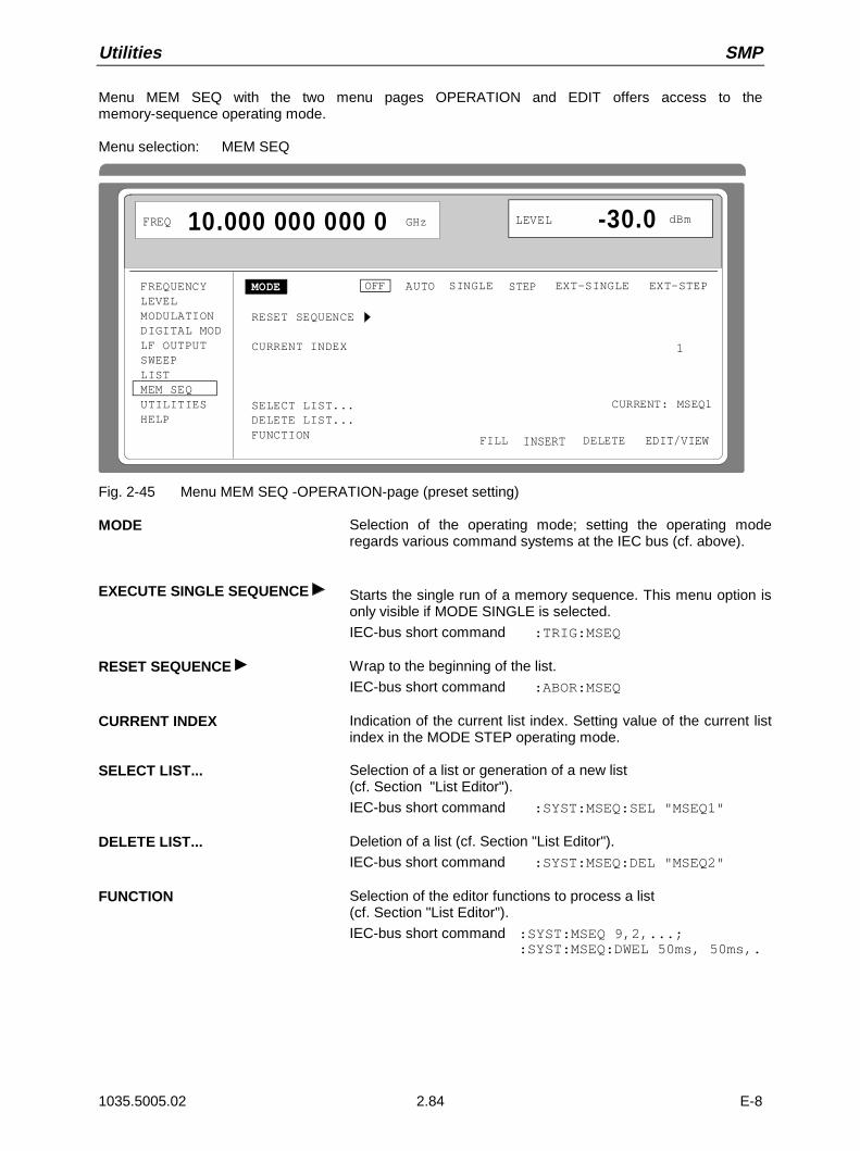
Utilities SMP
1035.5005.02 2.84 E-8
Menu MEM SEQ with the two menu pages OPERATION and EDIT offers access to thememory-sequence operating mode.
Menu selection: MEM SEQ
FREQUENCYLEVELMODULATIONDIGITAL MODLF OUTPUTSWEEPLISTMEM SEQUTILITIESHELP
MODE
RESET SEQUENCE
CURRENT INDEX
SELECT LIST...DELETE LIST...FUNCTION
OFF AUTO EXT-SINGLE EXT-STEPSTEP
CURRENT: MSEQ1
DELETE
FREQ 10.000 000 000 0 GHz LEVEL -30.0 dBm
SINGLE
INSERTFILL EDIT/VIEW
1
Fig. 2-45 Menu MEM SEQ -OPERATION-page (preset setting)
MODE Selection of the operating mode; setting the operating moderegards various command systems at the IEC bus (cf. above).
EXECUTE SINGLE SEQUENCE Starts the single run of a memory sequence. This menu option isonly visible if MODE SINGLE is selected.
IEC-bus short command :TRIG:MSEQ
RESET SEQUENCE Wrap to the beginning of the list.
IEC-bus short command :ABOR:MSEQ
CURRENT INDEX Indication of the current list index. Setting value of the current listindex in the MODE STEP operating mode.
SELECT LIST... Selection of a list or generation of a new list(cf. Section "List Editor").
IEC-bus short command :SYST:MSEQ:SEL "MSEQ1"
DELETE LIST... Deletion of a list (cf. Section "List Editor").
IEC-bus short command :SYST:MSEQ:DEL "MSEQ2"
FUNCTION Selection of the editor functions to process a list(cf. Section "List Editor").
IEC-bus short command :SYST:MSEQ 9,2,...;:SYST:MSEQ:DWEL 50ms, 50ms,.

SMP Utilities
1035.5005.02 2.85 E-8
The second page of menu MEM SEQ, the EDIT page, is automatically activated if one of the editorfunctions of the FUNCTION line is selected. The list which is entered as CURRENT LIST in theSELECT LIST line is shown.
FREQUENCYLEVELMODULATIONDIGITAL MODLF OUTPUTSWEEPLISTMEM SEQUTILITIESHELP
CURRENT: MSEQ1DELETE
FREQ 10.000 000 000 0 GHz LEVEL -30.0 dBm
INSERTFILL EDIT/VIEWSELECT LIST...FUNCTION-INDEX - FREE 2041 - LEN 2055 MEMORY DWELL 001 09 50 ms 002 02 50 ms 003 01 60 ms 004 23 60 ms 005 09 85 ms 006 10 85 ms 007 08 85 ms 008 11 85 ms
Fig 2-46 Menu MEM SEQ - EDIT page
INDEX Index of the list.
FREE Indication of the list entries still vacant.
LEN Length of the current list.
MEMORY Parameter: number of memory location; range 1 to 50.
DWELL Parameter: dwell time; specified range 50 ms to 60 sec, step width 1 ms.
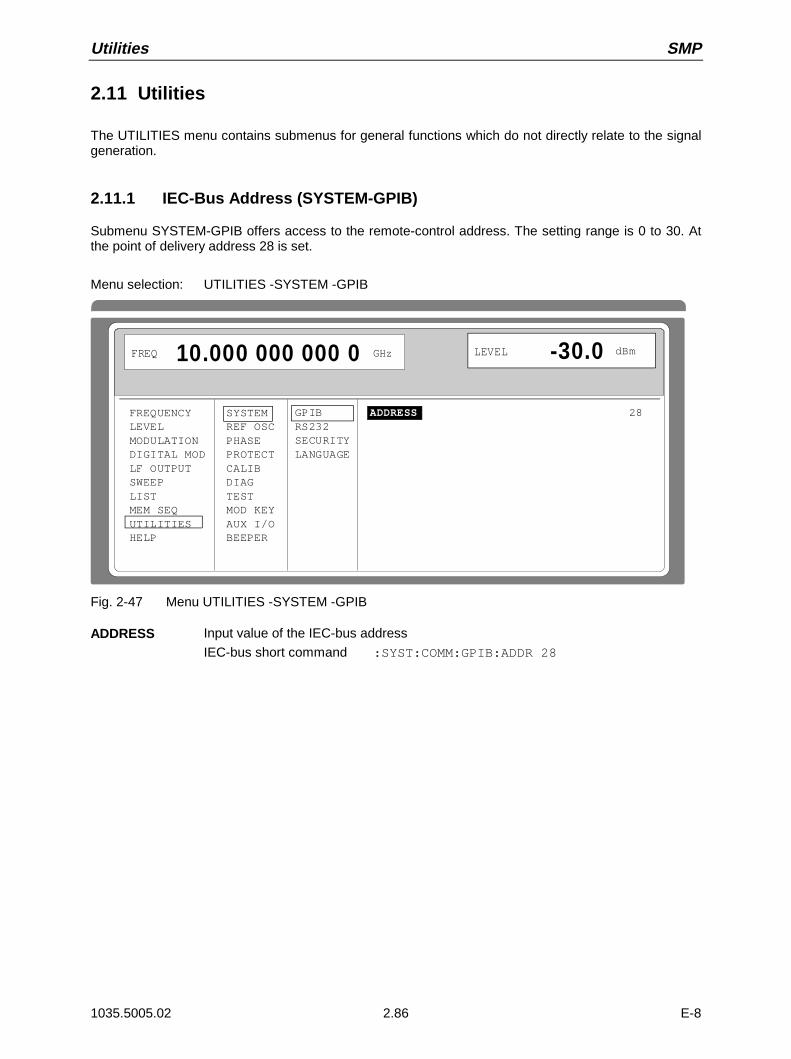
Utilities SMP
1035.5005.02 2.86 E-8
2.11 Utilities
The UTILITIES menu contains submenus for general functions which do not directly relate to the signalgeneration.
2.11.1 IEC-Bus Address (SYSTEM-GPIB)
Submenu SYSTEM-GPIB offers access to the remote-control address. The setting range is 0 to 30. Atthe point of delivery address 28 is set.
Menu selection: UTILITIES -SYSTEM -GPIB
FREQUENCYLEVELMODULATIONDIGITAL MODLF OUTPUTSWEEPLISTMEM SEQUTILITIESHELP
SYSTEMREF OSCPHASEPROTECTCALIBDIAGTESTMOD KEYAUX I/OBEEPER
ADDRESS
FREQ 10.000 000 000 0 GHz LEVEL -30.0 dBm
GPIBRS232SECURITYLANGUAGE
28
Fig. 2-47 Menu UTILITIES -SYSTEM -GPIB
ADDRESS Input value of the IEC-bus address
IEC-bus short command :SYST:COMM:GPIB:ADDR 28

SMP Utilities
1035.5005.02 2.87 E-8
2.11.2 Parameter of the RS232 Interface (SYSTEM-RS232)
Submenu SYSTEM-RS232 offers access to the configuration of the RS-232 interface. The pinassignment of the interface corresponds to the pin assignment of a PC.
Menu selection: UTILITIES - SYSTEM - RS232
FREQUENCYLEVELMODULATIONDIGITAL MODLF OUTPUTSWEEPLISTMEM SEQUTILITIESHELP
SYSTEMREF OSCPHASEPROTECTCALIBDIAGTESTMOD KEYAUX I/OBEEPER
DATA FORMAT 8 BitsPARITY NOSTOP BIT 1BAUD RATE 9600 bps HANDSHAKE OFF RTS/CTS XON/XOFF
FREQ 10.000 000 000 0 GHz LEVEL -30.0 dBm
GPIBRS232SECURITYLANGUAGE
Fig. 2-48 Menu UTILITIES - SYSTEM - RS232
DATA FORMAT Indication of the number of data bits. This value cannot be changed.
PARITY Indication of parity. This value cannot be changed.
STOP BIT Indication of the number of stop bits. This value cannot be changed.
BAUD RATE Selection of the baud rate.
IEC-bus short command :SYST:COMM:SER:BAUD 9600
HANDSHAKE Selection of the handshake.
OFF No handshake
IEC-bus short command :SYST:COMM:SER:PACE NONE
:SYST:COMM:SER:CONT:RTS ON
RTS/CTS Hardware handshake using the interface lines RTS and CTS. Thismode always is to be preferred to XON/XOFF mode, if permitted bythe configuration of the host computer.
IEC-bus short command :SYST:COMM:SER:CONT:RTS RFR
XON/XOFF Software handshake using the ASCII codes 11h <XON> and 13h<XOFF>. This mode is not recommended for binary data and forbaud rates above 9600 baud.
IEC-bus short command :SYST:COMM:SER:PACE XON
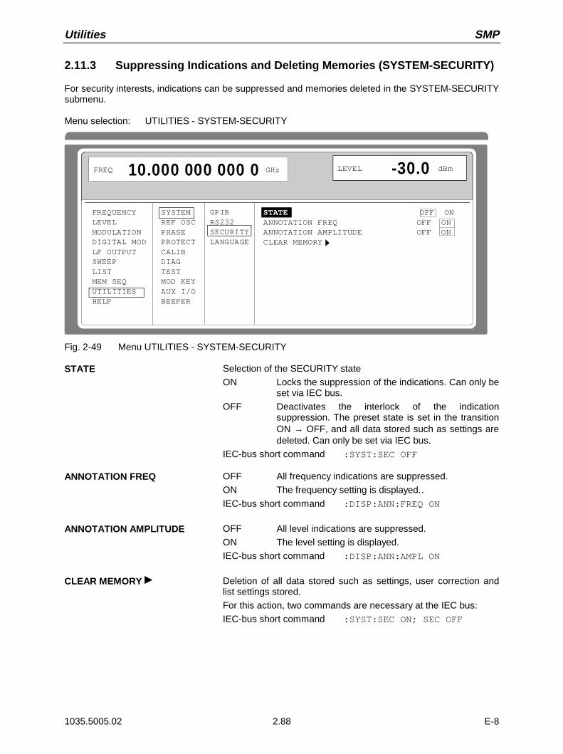
Utilities SMP
1035.5005.02 2.88 E-8
2.11.3 Suppressing Indications and Deleting Memories (SYSTEM-SECURITY)
For security interests, indications can be suppressed and memories deleted in the SYSTEM-SECURITYsubmenu.
Menu selection: UTILITIES - SYSTEM-SECURITY
FREQUENCYLEVELMODULATIONDIGITAL MODLF OUTPUTSWEEPLISTMEM SEQUTILITIESHELP
SYSTEMREF OSCPHASEPROTECTCALIBDIAGTESTMOD KEYAUX I/OBEEPER
STATE OFF ONANNOTATION FREQ OFF ONANNOTATION AMPLITUDE OFF ONCLEAR MEMORY
FREQ 10.000 000 000 0 GHz LEVEL -30.0 dBm
GPIBRS232SECURITYLANGUAGE
Fig. 2-49 Menu UTILITIES - SYSTEM-SECURITY
STATE Selection of the SECURITY state
ON Locks the suppression of the indications. Can only beset via IEC bus.
OFF Deactivates the interlock of the indicationsuppression. The preset state is set in the transitionON → OFF, and all data stored such as settings aredeleted. Can only be set via IEC bus.
IEC-bus short command :SYST:SEC OFF
ANNOTATION FREQ OFF All frequency indications are suppressed.
ON The frequency setting is displayed..IEC-bus short command :DISP:ANN:FREQ ON
ANNOTATION AMPLITUDE OFF All level indications are suppressed.
ON The level setting is displayed.
IEC-bus short command :DISP:ANN:AMPL ON
CLEAR MEMORY Deletion of all data stored such as settings, user correction andlist settings stored.
For this action, two commands are necessary at the IEC bus:
IEC-bus short command :SYST:SEC ON; SEC OFF
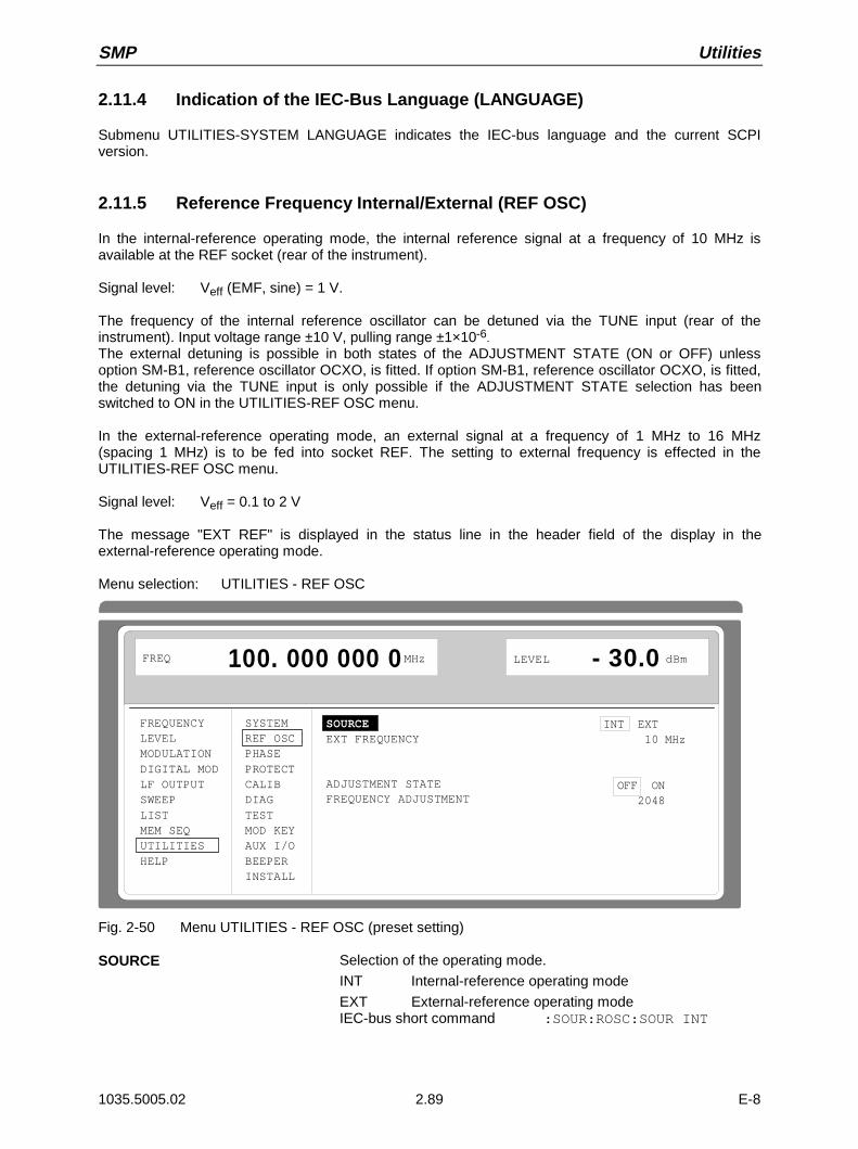
SMP Utilities
1035.5005.02 2.89 E-8
2.11.4 Indication of the IEC-Bus Language (LANGUAGE)
Submenu UTILITIES-SYSTEM LANGUAGE indicates the IEC-bus language and the current SCPIversion.
2.11.5 Reference Frequency Internal/External (REF OSC)
In the internal-reference operating mode, the internal reference signal at a frequency of 10 MHz isavailable at the REF socket (rear of the instrument).
Signal level: Veff (EMF, sine) = 1 V.
The frequency of the internal reference oscillator can be detuned via the TUNE input (rear of theinstrument). Input voltage range ±10 V, pulling range ±1×10⁻⁶.The external detuning is possible in both states of the ADJUSTMENT STATE (ON or OFF) unlessoption SM-B1, reference oscillator OCXO, is fitted. If option SM-B1, reference oscillator OCXO, is fitted,the detuning via the TUNE input is only possible if the ADJUSTMENT STATE selection has beenswitched to ON in the UTILITIES-REF OSC menu.
In the external-reference operating mode, an external signal at a frequency of 1 MHz to 16 MHz(spacing 1 MHz) is to be fed into socket REF. The setting to external frequency is effected in theUTILITIES-REF OSC menu.
Signal level: Veff = 0.1 to 2 V
The message "EXT REF" is displayed in the status line in the header field of the display in theexternal-reference operating mode.
Menu selection: UTILITIES - REF OSC
FREQUENCYLEVELMODULATIONDIGITAL MODLF OUTPUTSWEEPLISTMEM SEQUTILITIESHELP
SYSTEMREF OSCPHASEPROTECTCALIBDIAGTESTMOD KEYAUX I/OBEEPERINSTALL
SOURCE EXT FREQUENCY
ADJUSTMENT STATEFREQUENCY ADJUSTMENT
FREQ 100. 000 000 0 MHz LEVEL - 30.0 dBm
INT EXT 10 MHz
OFF ON 2048
Fig. 2-50 Menu UTILITIES - REF OSC (preset setting)
SOURCE Selection of the operating mode.
INT Internal-reference operating mode
EXT External-reference operating modeIEC-bus short command :SOUR:ROSC:SOUR INT
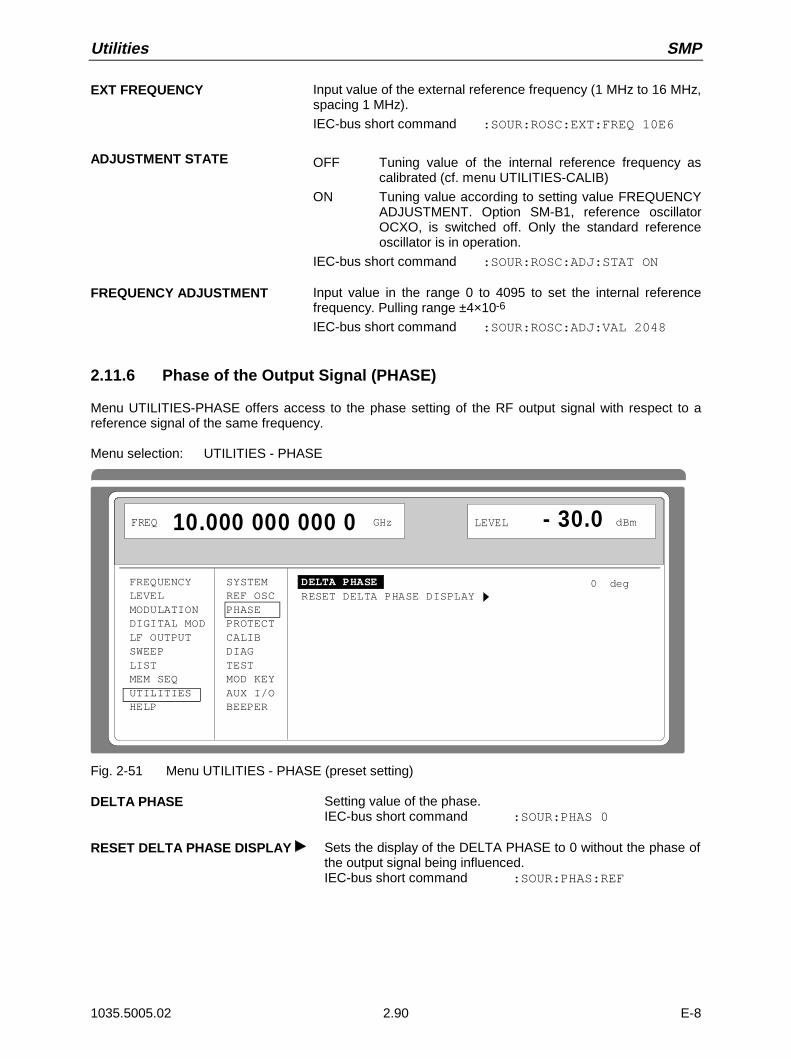
Utilities SMP
1035.5005.02 2.90 E-8
EXT FREQUENCY Input value of the external reference frequency (1 MHz to 16 MHz,spacing 1 MHz).
IEC-bus short command :SOUR:ROSC:EXT:FREQ 10E6
ADJUSTMENT STATE OFF Tuning value of the internal reference frequency ascalibrated (cf. menu UTILITIES-CALIB)
ON Tuning value according to setting value FREQUENCYADJUSTMENT. Option SM-B1, reference oscillatorOCXO, is switched off. Only the standard referenceoscillator is in operation.
IEC-bus short command :SOUR:ROSC:ADJ:STAT ON
FREQUENCY ADJUSTMENT Input value in the range 0 to 4095 to set the internal referencefrequency. Pulling range ±4×10⁻⁶
IEC-bus short command :SOUR:ROSC:ADJ:VAL 2048
2.11.6 Phase of the Output Signal (PHASE)
Menu UTILITIES-PHASE offers access to the phase setting of the RF output signal with respect to areference signal of the same frequency.
Menu selection: UTILITIES - PHASE
FREQUENCYLEVELMODULATIONDIGITAL MODLF OUTPUTSWEEPLISTMEM SEQUTILITIESHELP
SYSTEMREF OSCPHASEPROTECTCALIBDIAGTESTMOD KEYAUX I/OBEEPER
DELTA PHASE RESET DELTA PHASE DISPLAY
FREQ 10.000 000 000 0 GHz LEVEL - 30.0 dBm
0 deg
Fig. 2-51 Menu UTILITIES - PHASE (preset setting)
DELTA PHASE Setting value of the phase.IEC-bus short command :SOUR:PHAS 0
RESET DELTA PHASE DISPLAY Sets the display of the DELTA PHASE to 0 without the phase ofthe output signal being influenced.IEC-bus short command :SOUR:PHAS:REF

SMP Utilities
1035.5005.02 2.91 E-8
2.11.7 Password Input With Functions Protected (PROTECT)
The execution of calibrating and service functions is protected by a password. To unlock the lock-out,the correct password, a 6-digit number, has to be entered and then the [ENTER] key has to be pushed.After the instrument has been switched on, the lock-out is automatically activated.
Password 1 unlocks the lock-out for calibrations LEVEL, YFOM, ALC AMP, ALC LIMIT and PULSE GEN.
Password 2 unlocks the lock-out for calibration REF OSC.
Password 3 permits the input of the serial number and the value of the counter for POWER ON,operating hours and attenuator circuits.
Menu UTILITIES-PROTECT offers access to the unlocking of protected functions.
Menu selection: UTILITIES - PROTECT
FREQUENCYLEVELMODULATIONDIGITAL MODLF OUTPUTSWEEPLISTMEM SEQUTILITIESHELP
SYSTEMREF OSCPHASEPROTECTCALIBDIAGTESTMOD KEYAUX I/OBEEPER
LOCK LEVEL 1 PASSWORD LEVEL 1
LOCK LEVEL 2 PASSWORD LEVEL 2
LOCK LEVEL 3 PASSWORD LEVEL 3
FREQ 10.000 000 000 0 GHz LEVEL - 30.0 dBm
OFF ON XXXXXX
OFF ON XXXXXX
OFF ON XXXXXX
Fig. 2-52 Menu UTILITIES - PROTECT (preset setting)
LOCK LEVEL X Activating/deactivating the lock-out.
ON The lock-out is activated.
OFF The cursor automatically wraps to the input of thepassword. After the password has been entered, thelock-out is deactivated.
IEC-bus short command :SYST:PROT1 ON
PASSWORD LEVEL X Input of the password; termination with [ENTER] key.
IEC-bus short command :SYST:PROT1 OFF, 123456

Utilities SMP
1035.5005.02 2.92 E-8
2.11.8 Calibration (CALIB)
The following menus offer access to calibrating routines and correction values:UTILITIES - CALIB - PULSE GEN
REF OSC (cf. service manual)LEVEL (cf. service manual)YFOM (cf. service manual)ALC LIMIT (cf. service manual)ALC AMP (cf. service manual)LOOP GAIN (cf. service manual)
Caution: Execute calibration routines only when the instrument has warmed up.
Calibration routines LEVEL, REF OSC, YFOM, ALC AMP, ALC LIMIT and LOOP GAIN are described inthe service manual (stock no. 1035.5015.24).
Calibration PULSE GENA programmable oscillator determines the accuary of the pulse width and the pulse delay of the pulsegenerator.To compensate for the temperature dependence of the oscillator (approx. 0.2%/degree) aninternal calibration is offered. The adjustment accuracy is approx. +-0.5%. The calibration routine is tobe executed even after a data loss in the RAM or after an exchange of modules.
Function: The frequency of the oscillator is measured using a counter which is synchronized with thecrystal reference. The oscillator is readjusted until the deviation is minimized. Thecalibration value thus achieved is stored.
Internal calibration routine REF OSC is protected by a password. It can only be executed if the lock-outin the UTILITIES - PROTECT menu has been unlocked. The password is PASSWORD LEVEL 1 ="123456".
Menu selection: UTILITIES - CALIB - PULSE GEN
FREQUENCYLEVELMODULATIONDIGITAL MODLF OUTPUTSWEEPLISTMEM SEQUTILITIESHELP
SYSTEMREF OSCPHASEPROTECTCALIBDIAGTESTMOD KEYAUX I/OBEEPER
PULSE GENREF OSCLEVELYFOMALC LIMITALC AMPLOOP GAIN
FREQ 10.000 000 000 0 GHz LEVEL - 30.0 dBm
CALIBRATE
CALIBRATION DATA FINE OFCALIBRATION DATA COURSE 3E
Fig. 2-53 Menu UTILITIES - CALIB - PULSE GEN
CALIBRATE Triggers the calibration for the pulse generatorIEC-bus short command :CAL:PULS?
CALIBRATION DATA FINE Indication of the fine adustment in hexadecimal form.IEC-bus short command :CAL:PULS?
CALIBRATION DATA COURSE Indication of the course adustment in hexadecimal form.IEC-bus short command :CAL:PULS?

SMP Utilities
1035.5005.02 2.93 E-8
2.11.9 Indications of Module Variants (DIAG-CONFIG)
For service purposes, the modules installed can be indicated with their variants and states ofmodification. Submenu DIAG-CONFIG offers access to the module indication.
Menu selection: UTILITIES - DIAG - CONFIG
FREQUENCYLEVELMODULATIONDIGITAL MODLF OUTPUTSWEEPLISTMEM SEQUTILITIESHELP
SYSTEMREF OSCPHASEPROTECTCALIBDIAGTESTMOD KEYAUX I/OBEEPER
CONFIGTPOINTPARAM
FREQ 10.000 000 000 0 GHz LEVEL -30.0 dBm
VARVARVARVARVARVARVARVARVARVARVAR
REVREVREVREVREVREVREVREVREVREVREV
FRQREFSSDSYNSUMOPU1OPU3ROSC SM-B1LFGEN SM-B2FMOD SM-B5DCNV SMP-B11PUM20 SMP-B12
Fig. 2-54 Menu UTILITIES - DIAG - CONFIG
IEC-bus short command :DIAG:INFO:MOD?

Utilities SMP
1035.5005.02 2.94 E-8
2.11.10 Voltage Indication of Test Points (DIAG-TPOINT)
Submenu DIAG-TPOINT offers access to internal test points. If a test point is switched on, the voltageindication is displayed in a window in the header field. For greater detail, see service manual (stock no.1035.5015.24).
Menu selection: UTILITIES - DIAG - TPOINT
FREQUENCYLEVELMODULATIONDIGITAL MODLF OUTPUTSWEEPLISTMEM SEQUTILITIESHELP
SYSTEMREF OSCPHASEPROTECTCALIBDIAGTESTMOD KEYAUX I/OBEEPER
CONFIGTPOINTPARAM
FREQ 10.000 000 000 0 GHz
OFF ON 7
STATEPOINT
LEVEL -30.0 dBmTP 007+3.570V
Fig. 2-55 Menu UTILITIES - DIAG - TPOINT
STATE Switching on/off the voltage indication in the headerfield.
POINT........... Input value of the test point.
IEC-bus short command :DIAG:POINxx?
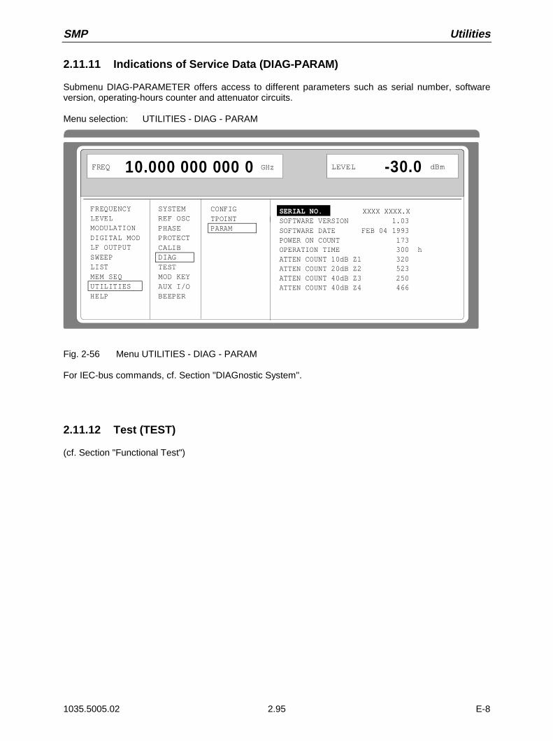
SMP Utilities
1035.5005.02 2.95 E-8
2.11.11 Indications of Service Data (DIAG-PARAM)
Submenu DIAG-PARAMETER offers access to different parameters such as serial number, softwareversion, operating-hours counter and attenuator circuits.
Menu selection: UTILITIES - DIAG - PARAM
FREQUENCYLEVELMODULATIONDIGITAL MODLF OUTPUTSWEEPLISTMEM SEQUTILITIESHELP
SYSTEMREF OSCPHASEPROTECTCALIBDIAGTESTMOD KEYAUX I/OBEEPER
CONFIGTPOINTPARAM
FREQ 10.000 000 000 0 GHz
LEVEL -30.0 dBm
SERIAL NO. XXXX XXXX.XSOFTWARE VERSION 1.03SOFTWARE DATE FEB 04 1993POWER ON COUNT 173OPERATION TIME 300 hATTEN COUNT 10dB Z1 320ATTEN COUNT 20dB Z2 523ATTEN COUNT 40dB Z3 250ATTEN COUNT 40dB Z4 466
Fig. 2-56 Menu UTILITIES - DIAG - PARAM
For IEC-bus commands, cf. Section "DIAGnostic System".
2.11.12 Test (TEST)
(cf. Section "Functional Test")
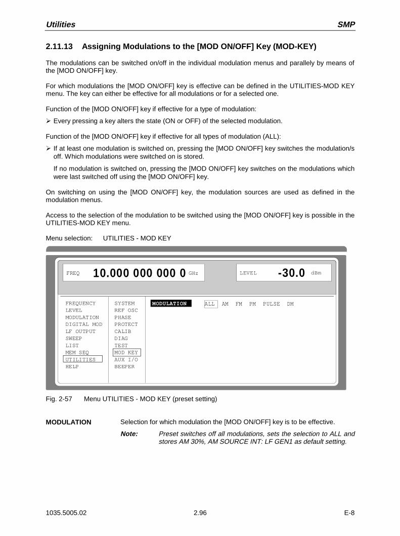
Utilities SMP
1035.5005.02 2.96 E-8
2.11.13 Assigning Modulations to the [MOD ON/OFF] Key (MOD-KEY)
The modulations can be switched on/off in the individual modulation menus and parallely by means ofthe [MOD ON/OFF] key.
For which modulations the [MOD ON/OFF] key is effective can be defined in the UTILITIES-MOD KEYmenu. The key can either be effective for all modulations or for a selected one.
Function of the [MOD ON/OFF] key if effective for a type of modulation:
À Every pressing a key alters the state (ON or OFF) of the selected modulation.
Function of the [MOD ON/OFF] key if effective for all types of modulation (ALL):
À If at least one modulation is switched on, pressing the [MOD ON/OFF] key switches the modulation/soff. Which modulations were switched on is stored.
If no modulation is switched on, pressing the [MOD ON/OFF] key switches on the modulations whichwere last switched off using the [MOD ON/OFF] key.
On switching on using the [MOD ON/OFF] key, the modulation sources are used as defined in themodulation menus.
Access to the selection of the modulation to be switched using the [MOD ON/OFF] key is possible in theUTILITIES-MOD KEY menu.
Menu selection: UTILITIES - MOD KEY
FREQUENCYLEVELMODULATIONDIGITAL MODLF OUTPUTSWEEPLISTMEM SEQUTILITIESHELP
SYSTEMREF OSCPHASEPROTECTCALIBDIAGTESTMOD KEYAUX I/OBEEPER
MODULATION ALL AM FM PM PULSE DM
FREQ 10.000 000 000 0 GHz LEVEL -30.0 dBm
Fig. 2-57 Menu UTILITIES - MOD KEY (preset setting)
MODULATION Selection for which modulation the [MOD ON/OFF] key is to be effective.
Note: Preset switches off all modulations, sets the selection to ALL andstores AM 30%, AM SOURCE INT: LF GEN1 as default setting.
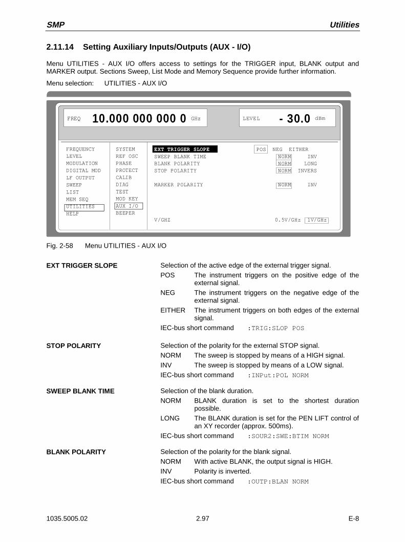
SMP Utilities
1035.5005.02 2.97 E-8
2.11.14 Setting Auxiliary Inputs/Outputs (AUX - I/O)
Menu UTILITIES - AUX I/O offers access to settings for the TRIGGER input, BLANK output andMARKER output. Sections Sweep, List Mode and Memory Sequence provide further information.
Menu selection: UTILITIES - AUX I/O
FREQUENCYLEVELMODULATIONDIGITAL MODLF OUTPUTSWEEPLISTMEM SEQUTILITIESHELP
SYSTEMREF OSCPHASEPROTECTCALIBDIAGTESTMOD KEYAUX I/OBEEPER
EXT TRIGGER SLOPE POS NEG EITHERSWEEP BLANK TIME NORM INVBLANK POLARITY NORM LONGSTOP POLARITY NORM INVERS MARKER POLARITY NORM INV Z-AXIS BLANK 5.0 VZ-AXIS MARKER -5.0 V V/GHZ 0.5V/GHz 1V/GHz
FREQ 10.000 000 000 0 GHz LEVEL - 30.0 dBm
Fig. 2-58 Menu UTILITIES - AUX I/O
EXT TRIGGER SLOPE Selection of the active edge of the external trigger signal.
POS The instrument triggers on the positive edge of theexternal signal.
NEG The instrument triggers on the negative edge of theexternal signal.
EITHER The instrument triggers on both edges of the externalsignal.
IEC-bus short command :TRIG:SLOP POS
STOP POLARITY Selection of the polarity for the external STOP signal.
NORM The sweep is stopped by means of a HIGH signal.
INV The sweep is stopped by means of a LOW signal.
IEC-bus short command :INPut:POL NORM
SWEEP BLANK TIME Selection of the blank duration.
NORM BLANK duration is set to the shortest durationpossible.
LONG The BLANK duration is set for the PEN LIFT control ofan XY recorder (approx. 500ms).
IEC-bus short command :SOUR2:SWE:BTIM NORM
BLANK POLARITY Selection of the polarity for the blank signal.
NORM With active BLANK, the output signal is HIGH.
INV Polarity is inverted.
IEC-bus short command :OUTP:BLAN NORM
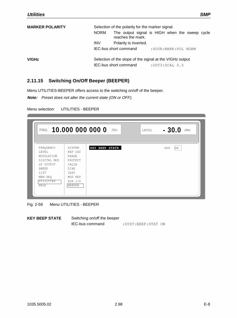
Utilities SMP
1035.5005.02 2.98 E-8
MARKER POLARITY Selection of the polarity for the marker signal.
NORM The output signal is HIGH when the sweep cyclereaches the mark.
INV Polarity is inverted.
IEC-bus short command :SOUR:MARK:POL NORM
V/GHz Selection of the slope of the signal at the V/GHz output
IEC-bus short command :OUT3:SCAL 0.5
2.11.15 Switching On/Off Beeper (BEEPER)
Menu UTILITIES-BEEPER offers access to the switching on/off of the beeper.
Note: Preset does not alter the current state (ON or OFF).
Menu selection: UTILITIES - BEEPER
FREQUENCYLEVELMODULATIONDIGITAL MODLF OUTPUTSWEEPLISTMEM SEQUTILITIESHELP
SYSTEMREF OSCPHASEPROTECTCALIBDIAGTESTMOD KEYAUX I/OBEEPER
KEY BEEP STATE OFF ON
FREQ 10.000 000 000 0 GHz LEVEL - 30.0 dBm
Fig. 2-59 Menu UTILITIES - BEEPER
KEY BEEP STATE Switching on/off the beeper
IEC-bus command :SYST:BEEP:STAT ON

SMP Status
1035.5005.02 2.99 E-8
2.12 The Help System
The SMP has two help systems. On the one hand the context-sensitive help which is called by means ofthe HELP key and which gives information on the current menu. On the other hand, auxiliary texts canbe selected according to headwords in alphabetical order by accessing menu HELP.
HELP Key
The yellow HELP key can be pressed at any point in time. The current setting menu is faded out andcontext-sensitive text faded in. The help panel can be exited by means of the RETURN key.
Menu HELP
After calling the help menu, access to all auxiliary texts is possible via an index. Operation is analog tomenu operation.
À Set the menu cursor to the index desired using the shaft encoder.
À Press the [SELECT] key.
À The information for the index marked is displayed.
À Press the [RETURN] key to exit the menu.
2.13 Status
By means of a STATUS page, the SMP permits an overview over all settings of the instrument. Thesettings are displayed in an abbreviated form. The STATUS page is called by pressing the [STATUS]key. Return to the preceding menu is effected using the [RETURN] key.
AM:OFF
FM1:DEV 123.00kHz; LF1FM2:OFF
PULSE:EXT TRIG DEL 1.00µs WID 1.00µs
FM1 PULSE
LF1: 1kHzLF2:123.4567kHz SINOUTPUT:1.234 LF2
SWEEP:OFF
REF OSC:10MHz INTTRIGGER SLOPE:POS
LOCALUNLOCKED
FREQ 10.000 000 000 0 GHz
FM1 PULSE
LEVEL - 30.0 dBm
Fig. 2-60 Menu STATUS page

Error Messages SMP
1035.5005.02 2.100 E-8
2.14 Error Messages
The SMP displays error and caution messages in a different manner, depending on how long, for a shortperiod of time or permanently, the cause exists.
Short-term message The short-term message is displayed in the status line. Part of itoverwrites the status indications and disappears after approx. 2seconds or in the case of a new entry.The instrument shows, e.g., short-term messages if the attempt ismade to enter an overrange or if incompatible operating modesdeactivate one another.
Long-term message The long-term message is displayed in the status line by means ofthe message "WARNING" or "ERROR". Pressing the [ERROR] keycalls the ERROR page in which the messages are entered. Severalmessages can be entered at the same time. The long-term messageremains existing until there is no cause any more. The ERROR pageis exited using the [RETURN] key.The instrument displays, e.g., the long-term message "ERROR" ifthere is a hardware error or "WARNING" if overrange settings havebeen made.
Notes: – An error message "ERROR" does not necessarily point to a defect instrument. There arevarious operating states which can cause an ERROR message. E. g. if the instrument is setto external reference but no external reference is connected.
– Error 313 indicates the loss of calibration data and is also applicable in case of a cold start(key [PRESET] is pressed during switch-on). The calibration values can be restored withinternal calibration routines. These routines are accessible via menu UTILITIES-CALIB (seesection on calibration).
The ERROR page offers access to long-term messages if the [ERROR] key is pressed.
WARNING -221 Settings conflict; modulation forces peak level into overrangeERROR 211 Summing loop unlockedWarning 153 Input voltage out of range; EXT1 too low
FREQ 10.000 000 000 0 GHz
AM
LEVEL - 12.0 dBm
EXT1-LOW ERROR
Fig. 2-61 ERROR page
A list of the possible error messages is t o be found in annex B.
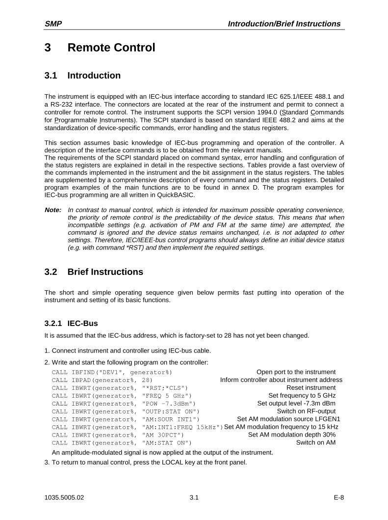
SMP Introduction/Brief Instructions
1035.5005.02 3.1 E-8
3 Remote Control
3.1 Introduction
The instrument is equipped with an IEC-bus interface according to standard IEC 625.1/IEEE 488.1 anda RS-232 interface. The connectors are located at the rear of the instrument and permit to connect acontroller for remote control. The instrument supports the SCPI version 1994.0 (Standard Commandsfor Programmable Instruments). The SCPI standard is based on standard IEEE 488.2 and aims at thestandardization of device-specific commands, error handling and the status registers.
This section assumes basic knowledge of IEC-bus programming and operation of the controller. Adescription of the interface commands is to be obtained from the relevant manuals.The requirements of the SCPI standard placed on command syntax, error handling and configuration ofthe status registers are explained in detail in the respective sections. Tables provide a fast overview ofthe commands implemented in the instrument and the bit assignment in the status registers. The tablesare supplemented by a comprehensive description of every command and the status registers. Detailedprogram examples of the main functions are to be found in annex D. The program examples forIEC-bus programming are all written in QuickBASIC.
Note: In contrast to manual control, which is intended for maximum possible operating convenience,the priority of remote control is the predictability of the device status. This means that whenincompatible settings (e.g. activation of PM and FM at the same time) are attempted, thecommand is ignored and the device status remains unchanged, i.e. is not adapted to othersettings. Therefore, IEC/IEEE-bus control programs should always define an initial device status(e.g. with command *RST) and then implement the required settings.
3.2 Brief Instructions
The short and simple operating sequence given below permits fast putting into operation of theinstrument and setting of its basic functions.
3.2.1 IEC-Bus
It is assumed that the IEC-bus address, which is factory-set to 28 has not yet been changed.
1. Connect instrument and controller using IEC-bus cable.
2. Write and start the following program on the controller:
CALL IBFIND("DEV1", generator%) Open port to the instrumentCALL IBPAD(generator%, 28) Inform controller about instrument addressCALL IBWRT(generator%, "*RST;*CLS") Reset instrumentCALL IBWRT(generator%, "FREQ 5 GHz") Set frequency to 5 GHzCALL IBWRT(generator%, "POW -7.3dBm") Set output level -7.3m dBmCALL IBWRT(generator%, "OUTP:STAT ON") Switch on RF-outputCALL IBWRT(generator%, "AM:SOUR INT1") Set AM modulation source LFGEN1CALL IBWRT(generator%, "AM:INT1:FREQ 15kHz")Set AM modulation frequency to 15 kHzCALL IBWRT(generator%, "AM 30PCT") Set AM modulation depth 30%CALL IBWRT(generator%, "AM:STAT ON") Switch on AM
An amplitude-modulated signal is now applied at the output of the instrument.
3. To return to manual control, press the LOCAL key at the front panel.

Introduction/Brief Instructions SMP
1035.5005.02 3.2 E-8
3.2.2 RS-232 Interface
It is assumed that the configuration of the RS-232 interface at the unit has not yet been changed.
1. Connect unit and controller using the 0-modem cable.
2. Enter the following command at the controller to configure the controller interface:
mode com1: 9600, n, 8, 1
3. Create the following ASCII file:
*RST;*CLSFREQ 5 GHzPOW -7.3dBmOUTP:STAT ONAM:SOUR INT1AM:INT1:FREQ 15kHzAM 30PCTAM:STAT ON
Switch instrument to remote control (Return key)Reset instrumentSet frequency 5 GHzSet output level -7.3 dBmSwitch on RF outputSet AM modulation source LFGEN1Set modulation frequency 15 kHzSet AM modulation depth 30%Switch on AM(Return key)
4. Transfer ASCII file to unit via RS-232 interface. Enter the following command at the controller:
copy <filename> com1:
An amplitude-modulated signal is now applied at the output of the instrument.
5. To return to manual control, press the [LOCAL] key at the front panel.
3.3 Switchover to Remote Control
On power-on, the instrument is always in the manual operating state ("LOCAL" state) and can beoperated via the front panel.
The instrument is switched to remote control ("REMOTE" state)
IEC-bus as soon as it receives an addressed command from a controller.
RS-232 as soon as it receives either a carriage return <CR> (=0Dh) or a line feed <LF> (0Ah) froma controller.
During remote control, operation via the front panel is disabled. The instrument remains in the remotestate until it is reset to the manual state via the front panel or via IEC bus. Switching from manualoperation to remote control and vice versa does not affect the remaining instrument settings.

SMP Switchover to Remote Control
1035.5005.02 3.3 E-8
3.3.1 Remote Control via IEC Bus
3.3.1.1 Setting the Device Address
The IEC-bus address of the instrument is factory-set to 28. It can be changed manually in theUTILITIES-SYSTEM-GPIB-ADDRESS menu or via IEC bus. Addresses 0 to 30 are permissible.
Manually:
À Call UTILITIES-SYSTEM-GPIB-ADDRESS menuÀ Enter desired addressÀ Terminate input using the [1x/ENTER] key
Via IEC bus:
CALL IBFIND("DEV1", generator%) Open port to the instrumentCALL IBPAD(generator%, 28) Inform controller about old
addressCALL IBWRT(generator%, "SYST:COMM:GPIB:ADDR 20") Set instrument to new addressCALL IBPAD(generator%, 20) Inform controller about new
address
3.3.1.2 Indications during Remote Control
The state of the remote control is evident by the words "IEC REMOTE" or "LOCAL" on the STATUSpage. The STATUS page is always displayed in the REMOTE state.LOCKED indicates that the key [LOCAL] is disabled, i.e. switchover to manual operation is only possiblevia IEC/IEEE bus. With UNLOCKED indicated, switchover to manual control is possible via the key[LOCAL].
3.3.1.3 Return to Manual Operation
Return to manual operation is possible via the front panel or the IEC bus.
Manually: À Press the [LOCAL] key.
Notes:
– Before switchover, command processing must be completed as otherwiseswitchover to remote control is effected immediately.
– The [LOCAL] key can be disabled by the universal command LLO (seeannex A) in order to prevent unintentional switchover. In this case,switchover to manual mode is only possible via the IEC bus.
– The [LOCAL] key can be enabled again by deactivating the REN control lineof the IEC bus (see annex A).
Via IEC bus: ...CALL IBLOC(generator%) Set instrument to manual operation....
Messages SMP
1035.5005.02 3.4 E-8
3.3.2 Remote Control via RS-232-Interface
3.3.2.1 Setting the Transmission Parameters
To enable an error-free and correct data transmission, the parameters of the unit and the controllershould have the same setting. To prevent any problems during binary data transmission, the RS-232interface is set for 8 data bits, no parity and 1 stop bit. This data format corresponds to the current IEEEP1174 standard. Parameters baud rate and handshake can be manually changed in menuUTILITIES-SYSTEM-RS-232.
À Call UTILITIES-SYSTEM-RS232 menu
À Select desired baudrate and handshake
À Terminate input using the [1x/ENTER] key
3.3.2.2 Indications during Remote Control
The state of the remote control is evident by the words "RS-232 REMOTE" or "LOCAL" on the STATUSpage. The STATUS page is always displayed in the REMOTE state.
3.3.2.3 Return to Manual Operating
Return to manual operation is possible via the front panel.
ÀPress the [LOCAL] key.
Note: Before switchover, command processing must be completed as otherwiseswitchover to remote control is effected immediately.
3.4 Messages
The messages transferred via the data lines of the IEC bus (see annex A) can be divided into twogroups:
- interface messages and- device messages.
No interface messages are defined for the RS-232 interface.
3.4.1 Interface Message
Interface messages are transferred on the data lines of the IEC bus, the ATN control line being active.They are used for communication between controller and instrument and can only be sent by acontroller which has the IEC-bus control. Interface commands can be subdivided into
- universal commands and- addressed commands.
Universal commands act on all devices connected to the IEC bus without previous addressing,addressed commands only act on devices previously addressed as listeners. The interface messagesrelevant to the instrument are listed in annex A.
Some control characters are defined for the control of the RS-232-interface (see annex A)

SMP Structure and Syntax of the Messages
1035.5005.02 3.5 E-8
3.4.2 Device Messages (Commands and Device Responses)
Device messages are transferred on the data lines of the IEC bus, the "ATN" control line not beingactive. ASCII code is used. The device messages are largely identical for the two interfaces (IEC busand RS-232).A distinction is made according to the direction in which they are sent on the IEC bus:
– Commands are messages the controller sends to the instrument. They operate the devicefunctions and request information.The commands are subdivided according to two criteria:
1. According to the effect they have on the instrument:
Setting commands cause instrument settings such as reset of theinstrument or setting the output level to 1 volt.
Queries cause data to be provided for output on the IEC-bus, e.g. for identification of the device or polling the active
input.
2. According to their definition in standard IEEE 488.2:
Common Commands are exactly defined as to their function and notation instandard IEEE 488.2. They refer to functions such asmanagement of the standardized status registers,reset and selftest.
Device-specific commands refer to functions depending on the features of theinstrument such as frequency setting. A majority ofthese commands has also been standardized by theSCPI committee.
– Device responses are messages the instrument sends to the controller after a query. They cancontain measurement results, instrument settings and information on theinstrument status.
Structure and syntax of the device messages are described in Section " Structure and Syntax of theDevice Messages". The commands are listed and explained in detail in Section " Description ofCommands".
3.5 Structure and Syntax of the Device Messages
3.5.1 SCPI Introduction
SCPI (Standard Commands for Programmable Instruments) describes a standard command set forprogramming instruments, irrespective of the type of instrument or manufacturer. The goal of the SCPIconsortium is to standardize the device-specific commands to a large extent. For this purpose, a modelwas developed which defines the same functions inside a device or for different devices. Commandsystems were generated which are assigned to these functions. Thus it is possible to address the samefunctions with identical commands. The command systems are of a hierarchical structure. Fig. 3-1illustrates this tree structure using a section of command system SOURce, which operates the signalsources of the devices. The other examples concerning syntax and structure of the commands arederived from this command system.
SCPI is based on standard IEEE 488.2, i.e. it uses the same syntactic basic elements as well as thecommon commands defined in this standard. Part of the syntax of the device responses is defined withgreater restrictions than in standard IEEE 488.2 (see Section "Responses to ").
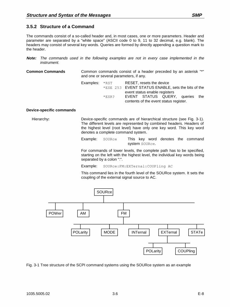
Structure and Syntax of the Messages SMP
1035.5005.02 3.6 E-8
3.5.2 Structure of a Command
The commands consist of a so-called header and, in most cases, one or more parameters. Header andparameter are separated by a "white space" (ASCII code 0 to 9, 11 to 32 decimal, e.g. blank). Theheaders may consist of several key words. Queries are formed by directly appending a question mark tothe header.
Note: The commands used in the following examples are not in every case implemented in theinstrument.
Common Commands Common commands consist of a header preceded by an asterisk "*"and one or several parameters, if any.
Examples: *RST RESET, resets the device*ESE 253 EVENT STATUS ENABLE, sets the bits of the
event status enable registers*ESR? EVENT STATUS QUERY, queries the
contents of the event status register.
Device-specific commands
Hierarchy: Device-specific commands are of hierarchical structure (see Fig. 3-1).The different levels are represented by combined headers. Headers ofthe highest level (root level) have only one key word. This key worddenotes a complete command system.
Example: SOURce This key word denotes the commandsystem SOURce.
For commands of lower levels, the complete path has to be specified,starting on the left with the highest level, the individual key words beingseparated by a colon ":".
Example: SOURce:FM:EXTernal:COUPling AC
This command lies in the fourth level of the SOURce system. It sets thecoupling of the external signal source to AC.
SOURce
POWer AM FM
MODE INTernal EXTernal STATePOLarity
POLarity COUPling
Fig. 3-1 Tree structure of the SCPI command systems using the SOURce system as an example
SMP Structure and Syntax of the Messages
1035.5005.02 3.7 E-8
Some key words occur in several levels within one command system. Theireffect depends on the structure of the command, that is to say, at whichposition in the header of a command they are inserted.
Example: SOURce:FM:POLarity NORMalThis command contains key word POLarity in the thirdcommand level. It defines the polarity between modulator andmodulation signal.
SOURce:FM:EXTernal:POLarity NORMalThis command contains key word POLarity in the fourthcommand level. It defines the polarity between modulationvoltage and the resulting direction of the modulation only for theexternal signal source indicated.
Optional key words: Some command systems permit certain key words to be optionally insertedinto the header or omitted. These key words are marked by squarebrackets in the description. The full command length must be recognizedby the instrument for reasons of compatibility with the SCPI standard.Some commands are considerably shortened by these optional key words.
Example: [SOURce]:POWer[:LEVel][:IMMediate]:OFFSet 1This command immediately sets the offset of the signal to 1volt. The following command has the same effect:POWer:OFFSet 1
Note: An optional key word must not be omitted if its effect is specifiedin detail by a numeric suffix.
Long and short form: The key words feature a long form and a short form. Either the short formor the long form can be entered, other abbreviations are not permissible.
Example: STATus:QUEStionable:ENABle 1= STAT:QUES:ENAB 1
Note: The short form is marked by upper-case letters, the long formcorresponds to the complete word. Upper-case and lower-casenotation only serve the above purpose, the instrument itselfdoes not make any difference between upper-case andlower-case letters.
Parameter: The parameter must be separated from the header by a "white space". Ifseveral parameters are specified in a command, they are separated by acomma ",". A few queries permit the parameters MINimum, MAXimum andDEFault to be entered. For a description of the types of parameter, refer toSection "Parameters".
Example: SOURce:POWer:ATTenuation? MAXimum Response: 60
This query requests the maximal value for the attenuation.
Numeric suffix: If a device features several functions or features of the same kind, e.g.inputs, the desired function can be selected by a suffix added to the com-mand. Entries without suffix are interpreted like entries with the suffix 1.
Example: SOURce:FM:EXTernal2:COUPling AC
This command sets the coupling of the second external signalsource.
Structure and Syntax of the Messages SMP
1035.5005.02 3.8 E-8
3.5.3 Structure of a Command Line
A command line may consist of one or several commands. It is terminated by a <New Line>, a <NewLine> with EOI or an EOI together with the last data byte. Quick BASIC automatically produces an EOItogether with the last data byte.
Several commands in a command line are separated by a semicolon ";". If the next command belongsto a different command system, the semicolon is followed by a colon.
Example:CALL IBWRT(generator%, "SOURce:POWer:CENTer MINimum;:OUTPut:ATTenuation 10")
This command line contains two commands. The first command is part of the SOURcesystem and is used to specify the center frequency of the output signal. The secondcommand is part of the OUTPut system and sets the attenuation of the output signal.
If the successive commands belong to the same system, having one or several levels in common, thecommand line can be abbreviated. To this end, the second command after the semicolon starts with thelevel that lies below the common levels (see also Fig. 3-1). The colon following the semicolon must beomitted in this case.
Example:CALL IBWRT(generator%, "SOURce:FM:MODE LOCKed;:SOURce:FM:INTernal:FREQuency 1kHz")
This command line is represented in its full length and contains two commands separatedfrom each other by the semicolon. Both commands are part of the SOURce commandsystem, subsystem FM, i.e. they have two common levels.When abbreviating the command line, the second command begins with the level belowSOURce:FM. The colon after the semicolon is omitted.
The abbreviated form of the command line reads as follows:
CALL IBWRT(generator%, "SOURce:FM:MODE LOCKed;INTernal:FREQuency 1kHz")
However, a new command line always begins with the complete path.
Example: CALL IBWRT(generator%, "SOURce:FM:MODE LOCKed")CALL IBWRT(generator%, "SOURce:FM:INTernal:FREQuency 1kHz")
3.5.4 Responses to Queries
A query is defined for each setting command unless explicitly specified otherwise. It is formed by addinga question mark to the associated setting command. According to SCPI, the responses to queries arepartly subject to stricter rules than in standard IEEE 488.2.
1. The requested parameter is transmitted without header.Example: SOURce:EXTernal:COUPling? Response: AC
2. Maximum values, minimum values and all further quantities, which are requested via a special text parameter are returned as numerical values.Example: FREQuency? MAX Response: 10E3
3. Numerical values are output without a unit. Physical quantities are referred to the basic units or to theunits set using the Unit command.
Example: FREQuency? Response: 1E6 for 1 MHz
4. Truth values <Boolean values> are returned as 0 (for OFF) and 1 (for ON).Example: OUTPut:STATe? Response: 1
5. Text (character data) is returned in a short form.Example: SOURce:FM:SOURce? Response: INT1
SMP Structure and Syntax of the Messages
1035.5005.02 3.9 E-8
3.5.5 Parameter
Most commands require a parameter to be specified. The parameters must be separated from theheader by a "white space". Permissible parameters are numerical values, Boolean parameters, text,character strings and block data. The type of parameter required for the respective command and thepermissible range of values are specified in the command description.
Numerical values Numerical values can be entered in any form, i.e. with sign, decimal point andexponent. Values exceeding the resolution of the instrument are rounded up ordown. The mantissa may comprise up to 255 characters, the exponent must lieinside the value range -32000 to 32000. The exponent is introduced by an "E"or "e". Entry of the exponent alone is not permissible. In the case of physicalquantities, the unit can be entered. Permissible unit prefixes are G (giga), MA(mega), MOHM and MHZ are also permissible), K (kilo), M (milli), U (micro)and N (nano). It the unit is missing, the basic unit is used.
Example: SOURce:FREQuency 1.5 kHz = SOURce:FREQuency 1.5E3
Special numerical The texts MINimum, MAXimum, DEFault, UP and DOWN are interpreted asvalues special numerical values.
In the case of a query, the numerical value is provided.
Example: Setting command: SOURce:VOLTage MAXimumQuery: SOURce:VOLTage? Response: 15
MIN/MAX MINimum and MAXimum denote the minimum and maximum value.
DEF DEFault denotes a preset value which has been stored in the EPROM. Thisvalue conforms to the default setting, as it is called by the *RST command.
UP/DOWN UP, DOWN increases or reduces the numerical value by one step. The stepwidth can be specified via an allocated step command (see annex C, List ofCommands) for each parameter which can be set via UP, DOWN.
INF/NINF INFinity, Negative INFinity (NINF) represent the numerical values -9.9E37 or9.9E37, respectively. INF and NINF are only sent as device responses.
NAN Not a Number (NAN) represents the value 9.91E37. NAN is only sent as deviceresponse. This value is not defined. Possible causes are the division of zero byzero, the subtraction of infinite from infinite and the representation of missingvalues.
Boolean Parameters Boolean parameters represent two states. The ON state (logically true) isrepresented by ON or a numerical value unequal to 0. The OFF state (logicallyuntrue) is represented by OFF or the numerical value 0. 0 or 1 is provided in aquery.
Example: Setting command: SOURce:FM:STATe ONQuery: SOURce:FM:STATe? Response: 1
Text Text parameters observe the syntactic rules for key words, i.e. they can beentered using a short or long form. Like any parameter, they have to beseparated from the header by a white space. In the case of a query, the shortform of the text is provided.
Example: Setting command: OUTPut:FILTer:TYPE EXTernalQuery: OUTPut:FILTer:TYPE? Response: EXT

Structure and Syntax of the Messages SMP
1035.5005.02 3.10 E-8
Strings Strings must always be entered in quotation marks (’ or ").
Example: SYSTem:LANGuage "SCPI" orSYSTem:LANGuage ’SCPI’
Block data Block data are a transmission format which is suitable for the transmission oflarge amounts of data. A command using a block data parameter has thefollowing structure:
Example: HEADer:HEADer #45168xxxxxxxx
ASCII character # introduces the data block. The next number indicates howmany of the following digits describe the length of the data block. In the examplethe 4 following digits indicate the length to be 5168 bytes. The data bytes follow.During the transmission of these data bytes all End or other control signs areignored until all bytes are transmitted. Data elements comprising more than onebyte are transmitted with the byte being the first which was specified by SCPIcommand "FORMat:BORDer".
The format of the binary files within the block depends on the IEC-buscommandThe commands
:SOURce:LIST:DWELl :SOURce:LIST:FREQuency :SOURce:LIST:POWer :SOURce:CORRection:CSET:DATA:FREQuency :SOURce:CORRection:CSET:DATA:POWer :SYSTem:MSEQuence:DWELl :SYSTem:MSEQuence:RCL
use the IEEE-754 format for double precision floating point numbers. Eachnumber is represented by 8 bytes.
Example:
a# = 125.345678E6b# = 127.876543E6
CALL IBWRT(generator%, "SOURCE:CORRECTION:CSET:DATA:FREQ#216" + MKD$(a#) + MKD$(b#))
– '#' in the command string introduces the binary block,– '2' indicates that 2 digits specifying the length will follow next,– '16' is the length of the binary block (in bytes), here: 2 double precision
floating pooint number with 8 bytes each.– The actual binary data follow now. As the function IBWRT requires a text
string, MKD$ is used for the type conversion.
The following ASCII format has the same effect:
CALL IBWRT(generator%, "SOURCE:CORRECTION:CSET:DATA:FREQ125.345678E6, 127.876543E6")

SMP Structure and Syntax of the Messages
1035.5005.02 3.11 E-8
3.5.6 Overview of Syntax Elements
The following survey offers an overview of the syntax elements.
:
;
,
?
*
"
#
The colon separates the key words of a command.In a command line the separating semicolon marks the uppermost command level.
The semicolon separates two commands of a command line. It does not alter the path.
The comma separates several parameters of a command.
The question mark forms a query.
The asterix marks a common command.
Quotation marks introduce a string and terminate it.
ASCI character # introduces block data.
A "white space" (ASCII-Code 0 to 9, 11 to 32 decimal, e.g. blank) separatesheader and parameter.
Description of Commands – Notation SMP
1035.5005.02 3.12 E-8
3.6 Description of Commands
3.6.1 Notation
In the following sections, all commands implemented in the instrument are first listed in tables and thendescribed in detail, separated according to the command system. The notation corresponds to the oneof the SCPI standards to a large extent. The SCPI conformity information can be taken from the list ofcommands in annex C.
Table of CommandsCommand: In the command column, the table provides an overview of the commands
and their hierarchical arrangement (see indentations).
Parameter: In the parameter column the requested parameters are indicated togetherwith their specified range.
Unit: The unit column indicates the basic unit of the physical parameters.
Remark: In the remark column an indication is made on- whether the command does not have a query form,- whether the command has only one query form ,- whether this command is implemented only with a certain option of the
instrument.
Indentations The different levels of the SCPI command hierarchy are represented in thetable by means of indentations to the right. The lower the level is, thefarther the indentation to the right is. Please observe that the completenotation of the command always includes the higher levels as well.
Example: SOURce:FM:MODE is represented in the table as follows:
SOURce first level:FM second level
:MODE third level
In the individual description, the complete notation of the command isgiven. An example for each command and - if it exists - the default value iswritten out at the end of the individual description.
Upper/lower case Upper/lower case letters serve to mark the long or short form of the keynotation words of a command in the description. The instrument itself does not
distinguish between upper and lower case letters.

SMP Description of Commands – Notation
1035.5005.02 3.13 E-8
Special characters | A selection of key words with an identical effect exists for severalcommands. These key words are indicated in the same line, they areseparated by a vertical stroke. Only one of these key words has to beindicated in the header of the command. The effect of the command isindependent of which of the key words is indicated.
Example:SOURce:FREQuency
:CW|:FIXed
The two following commands of identical meaning can beformed. They set the frequency of the constantly frequent signalto 1 kHz:
SOURce:FREQuency:CW 1E3 = SOURce:FREQuency:FIXed 1E3
A vertical stroke in indicating the parameters marks alternative possibilitiesin the sense of "or". The effect of the command is different, depending onwhich parameter is entered.
Example:Selection of the parameters for the commandSOURce:COUPling AC | DC
If parameter AC is selected, only the AC content is fed through, inthe case of DC, the DC as well as the AC content.
[ ] Key words in square brackets can be omitted when composing the header(cf. Section "Optional Key"). The full command length must be accepted bythe instrument for reasons of compatibility with the SCPI standards.Parameters in square brackets can optionally be incorporated in thecommand or omitted as well.
Parameters in braces can optionally be incorporated in the command eithernot at all, once or several times.
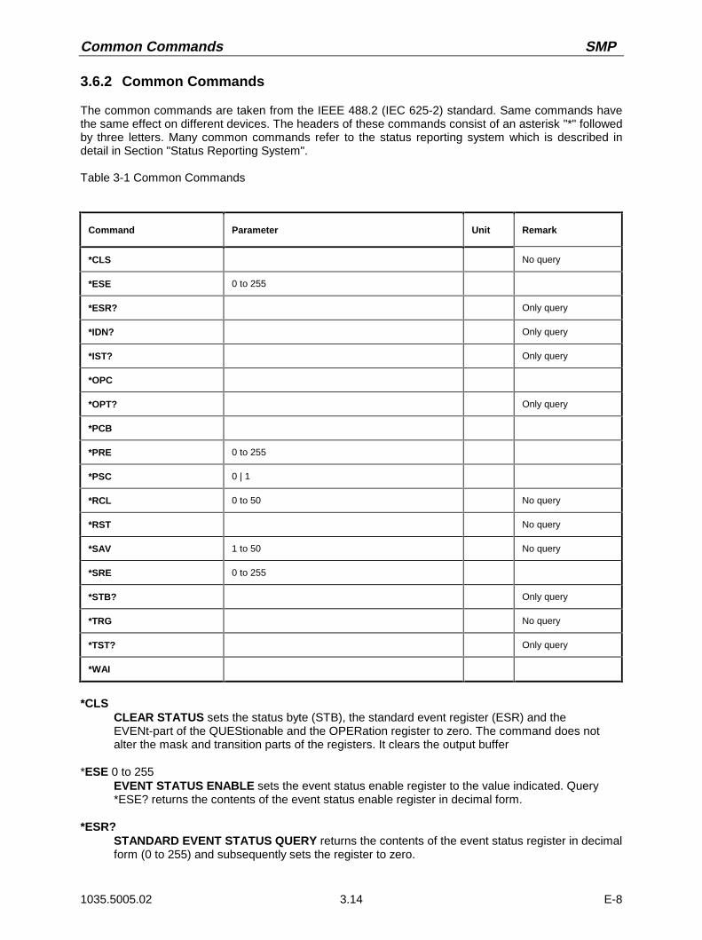
Common Commands SMP
1035.5005.02 3.14 E-8
3.6.2 Common Commands
The common commands are taken from the IEEE 488.2 (IEC 625-2) standard. Same commands havethe same effect on different devices. The headers of these commands consist of an asterisk "*" followedby three letters. Many common commands refer to the status reporting system which is described indetail in Section "Status Reporting System".
Table 3-1 Common Commands
Command Parameter Unit Remark
*CLS No query
*ESE 0 to 255
*ESR? Only query
*IDN? Only query
*IST? Only query
*OPC
*OPT? Only query
*PCB
*PRE 0 to 255
*PSC 0 | 1
*RCL 0 to 50 No query
*RST No query
*SAV 1 to 50 No query
*SRE 0 to 255
*STB? Only query
*TRG No query
*TST? Only query
*WAI
*CLSCLEAR STATUS sets the status byte (STB), the standard event register (ESR) and theEVENt-part of the QUEStionable and the OPERation register to zero. The command does notalter the mask and transition parts of the registers. It clears the output buffer
*ESE 0 to 255EVENT STATUS ENABLE sets the event status enable register to the value indicated. Query*ESE? returns the contents of the event status enable register in decimal form.
*ESR?STANDARD EVENT STATUS QUERY returns the contents of the event status register in decimalform (0 to 255) and subsequently sets the register to zero.

SMP Common Commands
1035.5005.02 3.15 E-8
*IDN?IDENTIFICATION QUERY queries the instrument identification.The device response is for example: "Rohde&Schwarz, SMP02,00000001, 1.04"
02 = variant identification00000001= serial number1.04 = firmware version number
*IST?INDIVIDUAL STATUS QUERY returns the contents of the IST flag in decimal form (0 | 1). TheIST flag is the status bit which is sent during a parallel poll.
*OPCOPERATION COMPLETE sets bit 0 in the event status register when all preceding commandshave been executed. This bit can be used to initiate a service request.
*OPT?OPTION IDENTIFICATION QUERY queries the options included in the instrument and returns alist of the options installed. The options are separated from each other by means of commas. Forevery option, a fixed position is provided in the response.
Table 3-2 Device Response to *OPT?
Position Option
1 SM-B1 Reference oscillator OCXO
2 SM-B2 LF generator
3 SM-B2 2nd LF generator
4 SM-B5 FM/ΦM modulator
5 reserved
6 reserved
7 reserved
8 SMP-B11 Frequency extension 0.01 to 2 GHz
9 SMP-B12 Pulse modulator 2 to 20/27/40 GHz
10 SMP-B13 Pulse modulator 0.01 to 2 GHz
11 SMP-B14 Pulse generator
12 SMP-B15 Attenuator 27 GHz
13 reserved
14 SMP-B17 Attenuator 40 GHz
15 SMP-B18 Auxiliary interface
Example for a device response: SM-B1,SM-B2,0,0,0,0,0,0,0,SMP-B15,0,0,0
Common Commands SMP
1035.5005.02 3.16 E-8
*PCBPASS CONTROL BACK indicates to the potental controller the address where the control is to bepassed back later. This command is sent by the current controller to a potential controller (seeprogramming example in Appendix D).
*PRE 0 to 255PARALLEL POLL REGISTER ENABLE sets the parallel poll enable register to the valueindicated. Query *PRE? returns the contents of the parallel poll enable register in decimal form.
*PSC 0 | 1POWER ON STATUS CLEAR determines whether the contents of the ENABle registers ismaintained or reset in switching on.
*PSC = 0 causes the contents of the status registers to be maintained. Thus a service requestcan be triggered in switching on in the case of a corresponding configuration ofstatus registers ESE and SRE.
*PSC ≠ 0 resets the registers.
Query *PSC? reads out the contents of the power-on-status-clear flag. The response can be 0 or 1.
*RCL 0 to 50RECALL calls the instrument state which was stored under the number supplied using command*SAV. 50 instrument states can be stored.
*RSTRESET sets the instrument to a defined default status. The command essentially corresponds topressing the [PRESET] key. The state of the RF-output is an exception: The RF-output isdeactivated after *RST, however, it is activated after the [RESET] key has been pressed. Thedefault setting is indicated in the description of the commands.
*SAV 1 to 50SAVE stores the current instrument state under the number indicated (cf. *RCL as well).
*SRE 0 to 255SERVICE REQUEST ENABLE sets the service request enable register to the value indicated. Bit6 (MSS mask bit) remains 0. This command determines under which conditions a service requestis triggered. Query *SRE? reads the contents of the service request enable register in decimalform. Bit 6 is always 0.
*STB?READ STATUS BYTE QUERY reads out the contents of the status byte in decimal form.
*TRG
TRIGGER triggers all actions waiting for a trigger event. Special trigger events can be started bycommand system "TRIGger" (see section "TRIGger System").
*TST?SELF TEST QUERY triggers all selftests of the instrument indicated in Section "Functional Test"and outputs an error code in decimal form.
*WAIWAIT-to-CONTINUE only permits the servicing of the subsequent commands after all precedingcommands have been executed and all signals have settled (cf. "*OPC" as well).

SMP ABORt
1035.5005.02 3.17 E-8
3.6.3 ABORt System
The ABORt system contains the commands to abort actions triggered. After an action has been aborted,it can be triggered again at once. All commands trigger an event, thus they have no *RST value.
Further commands for the trigger system of the SMP can be found in the TRIGger system.
Command Parameter DefaultUnit
Remark
:ABORt
[:SWEep]
:LIST
:MSEQuence
No query
No query
No query
:ABORt[:SWEep]The command aborts a sweep.
Example: :ABOR:SWE
:ABORt:LISTThe command aborts a list execution.
Example: :ABOR:LIST
:ABORt:MSEQuenceThe command aborts a Memory Sequence.
Example: :ABOR:MSEQ
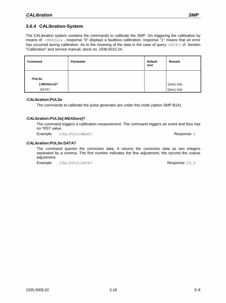
CALibration SMP
1035.5005.02 3.18 E-8
3.6.4 CALibration-System
The CALibration system contains the commands to calibrate the SMP. On triggering the calibration bymeans of :MEASure , response "0" displays a faultless calibration, response "1" means that an errorhas occurred during calibration. As to the meaning of the data in the case of query :DATA?, cf. Section"Calibration" and service manual, stock no. 1036.5015.24.
Command Parameter DefaultUnit
Remark
:PULSe
[:MEASure]?
:DATA?
Query only
Query only
:CALibration:PULSeThe commands to calibrate the pulse generator are under this node (option SMP-B14).
:CALibration:PULSe[:MEASure]?The command triggers a calibration measurement. The command triggers an event and thus hasno *RST value.
Example: :CAL:PULS:MEAS? Response: 0
:CALibration:PULSe:DATA?The command queries the correction data. It returns the correction data as two integersseparated by a comma. The first number indicates the fine adjustment, the second the coarseadjustment.
Example: :CAL:PULS:DATA? Response: 26,2
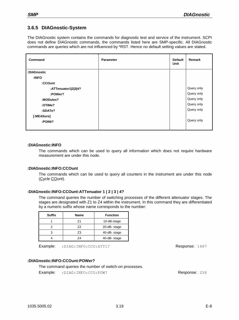
SMP DIAGnostic
1035.5005.02 3.19 E-8
3.6.5 DIAGnostic-System
The DIAGnostic system contains the commands for diagnostic test and service of the instrument. SCPIdoes not define DIAGnostic commands, the commands listed here are SMP-specific. All DIAGnosticcommands are queries which are not influenced by *RST. Hence no default setting values are stated.
Command Parameter DefaultUnit
Remark
:DIAGnostic
:INFO
:CCOunt
:ATTenuator1|2|3|4?
:POWer?
:MODules?
:OTIMe?
:SDATe?
[:MEASure]
:POINt?
Query only
Query only
Query only
Query only
Query only
Query only
:DIAGnostic:INFOThe commands which can be used to query all information which does not require hardwaremeasurement are under this node.
:DIAGnostic:INFO:CCOuntThe commands which can be used to query all counters in the instrument are under this node(Cycle COunt).
:DIAGnostic:INFO:CCOunt:ATTenuator 1 | 2 | 3 | 4?The command queries the number of switching processes of the different attenuator stages. Thestages are designated with Z1 to Z4 within the instrument. In this command they are differentiatedby a numeric suffix whose name corresponds to the number:
Suffix Name Function
1 Z1 10-dB-stage
2 Z2 20-dB- stage
3 Z3 40-dB- stage
4 Z4 40-dB- stage
Example: :DIAG:INFO:CCO:ATT1? Response: 1487
:DIAGnostic:INFO:CCOunt:POWer?The command queries the number of switch-on processes.
Example: :DIAG:INFO:CCO:POW? Response: 258
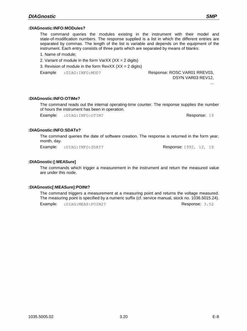
DIAGnostic SMP
1035.5005.02 3.20 E-8
:DIAGnostic:INFO:MODules?The command queries the modules existing in the instrument with their model andstate-of-modification numbers. The response supplied is a list in which the different entries areseparated by commas. The length of the list is variable and depends on the equipment of theinstrument. Each entry consists of three parts which are separated by means of blanks:
1. Name of module;
2. Variant of module in the form VarXX (XX = 2 digits)
3. Revision of module in the form RevXX (XX = 2 digits)
Example :DIAG:INFO:MOD? Response: ROSC VAR01 RREV03,DSYN VAR03 REV12,
...
:DIAGnostic:INFO:OTIMe?The command reads out the internal operating-time counter. The response supplies the numberof hours the instrument has been in operation.
Example: :DIAG:INFO:OTIM? Response: 19
:DIAGnostic:INFO:SDATe?The command queries the date of software creation. The response is returned in the form year,month, day.
Example: :DIAG:INFO:SDAT? Response: 1992, 12, 19
:DIAGnostic:[:MEASure]The commands which trigger a measurement in the instrument and return the measured valueare under this node.
:DIAGnostic[:MEASure]:POINt?The command triggers a measurement at a measuring point and returns the voltage measured.The measuring point is specified by a numeric suffix (cf. service manual, stock no. 1036.5015.24).
Example: :DIAG:MEAS:POIN2? Response: 3.52

SMP DISPlay
1035.5005.02 3.21 E-8
3.6.6 DISPLAY-System
This system contains the commands to configure the screen. If system security is activated usingcommand SYSTem:SECurity ON, the display cannot be switched on and off arbitrarily (cf. below)
Command Parameter DefaultUnit
Remark
:DISPlay
:ANNotation
[:ALL]
:AMPLitude
:FREQuency
ON | OFF
ON | OFF
ON | OFF
:DISPlay:ANNotationThe commands determining whether frequency and amplitude are indicated are under this node.
Caution: With SYSTem:SECurity ON, the indications cannot be switched from OFF to ON. Inthis case *RST does not influence the ANNotation settings either. WithSYSTem:SECurity OFF, the *RST value is ON for all ANNotation parameters.
:DISPlay:ANNotation[:ALL] ON | OFF
The command switches the frequency and amplitude indication on or off.
Command :DISPlay:ANNotation:ALL ON can only be executed if SYSTem:SECurity is setto OFF.
With SECurity OFF - *RST value is ON.
Example: :DISP:ANN:ALL ON
:DISPlay:ANNotation:AMPLitude ON | OFF
The command switches on or off the amplitude indication.
Command :DISPlay:ANNotation:AMPLitude ON can only be executed ifSYSTem:SECurity is set to OFF.
With SYSTem:SECurity OFF - *RST value is ON.
Example: :DISP:ANN:AMPL ON
:DISPlay:ANNotation:FREQuency ON | OFF
The command switches on or off the amplitude indication.
Command :DISPlay:ANNotation:AMPLitude ON can only be executed ifSYSTem:SECurity is set to OFF.
With SYSTem:SECurity OFF - *RST value is ON.
Example: :DISP:ANN:FREQ ON

FORMat SMP
1035.5005.02 3.22 E-8
3.6.7 FORMat-System
This system contains the commands determining the format of the data the SMP returns to thecontroller. All queries returning a list of numeric data or block data are concerned. With each of thesecommands, this connection is pointed to in the description.
Command Parameter DefaultUnit
Remark
:FORMat
[:DATA]
:BORDer
ASCii | PACKed
NORMal | SWAPped
:FORMat[:DATA] ASCii | PACKed
The command specifies the data format, that the SMP uses for returning the data. When data aretransmitted from the controller to the SMP, the SMP recognizes the data format automatically. Inthis case, the value specified here has no significance.
Note: Settings using the FORMat:DATA command are only effective for commands wherethis is stated in the command description.
ASCii Numeric data are transmitted in plain text, separated by commas.
PACKed Numerical data are transmitted as binary block data. The format of the binary dataitself is command-specific.
Example: :FORM:DATA ASC *RST value is ASCii
:FORMat:BORDer NORMal | SWAPped
This command defines the order of bytes inside a binary block. This concerns only blocks whichuse the IEEE754 format internally (see section paragraph "Block Data").
NORMal: The SMP expects (for setting commands) and sends (for queries) first the mostsignificant byte of each IEEE-754 floating point number, last the least significantbyte. For hosts based on a 80x86 processor this corresponds to the configuration ofbytes in the main memory. Thus, no further conversion is required.
SWAPped: The SMP expects (for setting commands) and sends (for queries) first the leastsignificant byte of each IEEE754 floating point number, last the most significant byte.
Example: :FORMat:BORDer:NORMal *RST-value is NORMal
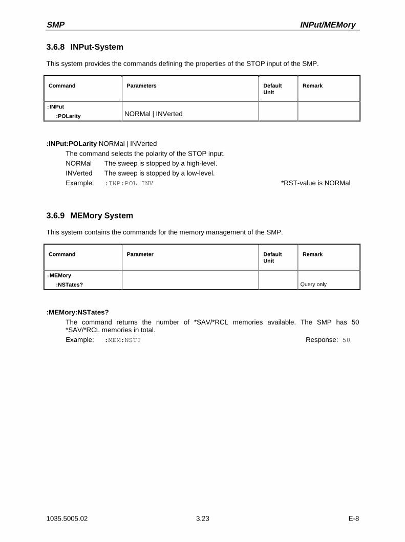
SMP INPut/MEMory
1035.5005.02 3.23 E-8
3.6.8 INPut-System
This system provides the commands defining the properties of the STOP input of the SMP.
Command Parameters DefaultUnit
Remark
:INPut
:POLarity NORMal | INVerted
:INPut:POLarity NORMal | INVerted
The command selects the polarity of the STOP input.
NORMal The sweep is stopped by a high-level.
INVerted The sweep is stopped by a low-level.
Example: :INP:POL INV *RST-value is NORMal
3.6.9 MEMory System
This system contains the commands for the memory management of the SMP.
Command Parameter DefaultUnit
Remark
:MEMory
:NSTates? Query only
:MEMory:NSTates?The command returns the number of *SAV/*RCL memories available. The SMP has 50*SAV/*RCL memories in total.
Example: :MEM:NST? Response: 50
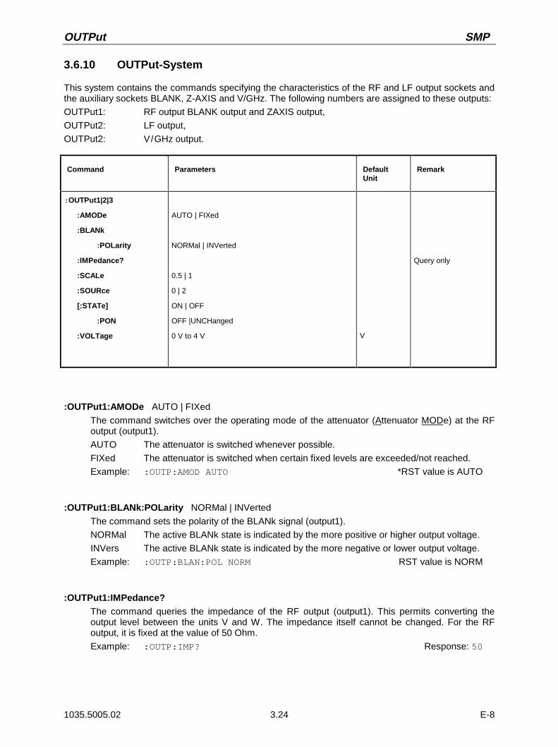
OUTPut SMP
1035.5005.02 3.24 E-8
3.6.10 OUTPut-System
This system contains the commands specifying the characteristics of the RF and LF output sockets andthe auxiliary sockets BLANK, Z-AXIS and V/GHz. The following numbers are assigned to these outputs:
OUTPut1: RF output BLANK output and ZAXIS output,
OUTPut2: LF output,
OUTPut2: V/GHz output.
Command Parameters DefaultUnit
Remark
:OUTPut1|2|3
:AMODe
:BLANk
:POLarity
:IMPedance?
:SCALe
:SOURce
[:STATe]
:PON
:VOLTage
AUTO | FIXed
NORMal | INVerted
0.5 | 1
0 | 2
ON | OFF
OFF |UNCHanged
0 V to 4 V V
Query only
:OUTPut1:AMODe AUTO | FIXed
The command switches over the operating mode of the attenuator (Attenuator MODe) at the RFoutput (output1).
AUTO The attenuator is switched whenever possible.
FIXed The attenuator is switched when certain fixed levels are exceeded/not reached.
Example: :OUTP:AMOD AUTO *RST value is AUTO
:OUTPut1:BLANk:POLarity NORMal | INVerted
The command sets the polarity of the BLANk signal (output1).
NORMal The active BLANk state is indicated by the more positive or higher output voltage.
INVers The active BLANk state is indicated by the more negative or lower output voltage.
Example: :OUTP:BLAN:POL NORM RST value is NORM
:OUTPut1:IMPedance?The command queries the impedance of the RF output (output1). This permits converting theoutput level between the units V and W. The impedance itself cannot be changed. For the RFoutput, it is fixed at the value of 50 Ohm.
Example: :OUTP:IMP? Response: 50

SMP OUTPut
1035.5005.02 3.25 E-8
:OUTPut3:SCALe 0.5 | 1
The command defines the signal scale at the V/GHz-output (output3) (see also section "SweepOutputs").
Example: :OUTP3:SCAL 0.5? *RST-value is 1
:OUTPut2:SOURce 0 | 2
The command selects which LF-generator is connected to the LF-output socket (output2). It isavailable with option SM-B2.
0 LF-generator 1
2 LF-generator 2
Example: :OUTP2:SOUR 2 *RST-value is 0, LF-generator 1 is connected to the output
:OUTPut1:STATe] ON | OFF
The command switches on or off the RF output (output1). The RF output can also be switched offby the response of the protective circuit. But this has no influence on this parameter.
Note: In contrast to the PRESET key, command *RST sets the value for output1 to OFF,the RF-output is deactivated.
Example: :OUTP:STAT ON *RST value is OFF
:OUTPut1[:STATe]:PON OFF | UNCHanged
This command selects the state the RF output (output1) is to assume after power-on of the unit. Itonly exists for the RF output. *RST does not influence the set value.
OFF Output is switched off.
UNCHanged Same state as before switch-off
Example: :OUTP:PON OFF
:OUTPut2:VOLTage 0V to 4V
The command sets the voltage of the LF-output (output2). The voltage is a characteristic of theoutput, not of the source. I.e., the voltage is maintained even if another generator is connected tothe output.
Example: :OUTP2:VOLT 3.0V *RST-value is 1V

SOURce:AM SMP
1035.5005.02 3.26 E-8
3.6.11 SOURce-System
This system contains the commands to configure the RF signal source. Keyword SOURce is optional,i.e., it can be omitted. The LF signal sources (option SM-B2) are configured in the SOURce0|2 system.
The following subsystems are realized in the instrument:
Subsystem Settings
[:SOURce]:AM:CORRection:DM:FM:FREQuency:LIST:MARKer:PHASe:PM:POWer:PULM:PULSe:ROSCillator:SWEep
Amplitude modulationCorrection of the output levelDigital modulationFrequency modulationFrequencies including sweepLIST operating modeMarker generation with sweepsPhase between output signal and reference oscillator signalPhase modulationOutput level, level control and level correctionPulse modulationPulse generatorReference oscillatorSweeps
3.6.11.1 SOURce:AM Subsystem
This subsystem contains the commands to control the amplitude modulation. Up to two LF generatorswhich serve as internal modulation sources can be fitted in the instrument (options SM-B2 and SM-B6).Part of their settings is effected under SOURce0|2.
Command Parameters DefaultUnit
Remark
[:SOURce]
:AM
[:DEPTh]
:EXTernal
:COUPling
:IMPedance
:INTernal1|2
:FREQuency
:SCAN
:SENSitivity
:SOURce:STATe
0 to 100PCT
AC | DC
600 Ohm | 100 kOhm
400 Hz, 1 kHz, 4 kHz, 15 kHz or
0.1 Hz to 500 kHz or 0.1 Hz to 1 MHz
ON | OFF
0 to 10 dB/V
EXT | INT1|2 | EXT, INT1|2
ON | OFF
PCT
Ohm
HzHz option SM-B2
[:SOURce]:AM[:DEPTh] 0 to 100PCT
The command sets the modulation depth in percent. *RST value is 30PCT
Example: :SOUR:AM:DEPT 15PCT
[:SOURce]:AM:EXTernalThe commands to set the external AM input are under this node.

SMP SOURce:AM
1035.5005.02 3.27 E-8
[:SOURce]:AM:EXTernal:COUPling AC | DC
The command selects the type of coupling for the external AM input.
AC The d.c. voltage content is separated from the modulation signal.
DC The modulation signal is not altered. *RST value is AC
Example: :SOUR:AM:EXT:COUP AC
[:SOURce]:AM:EXTernal:IMPedance 600Ohm | 100kOhm
The command defines the input impedance of the external AM-input. This command is coupled tothe commands
:SOURce:FM:EXTernal:IMPedance,
:SOURce:DM:EXTernal:IMPedance and
:SOURce:PM:EXTernal:IMPedance. *RST value is 100 kOhm
Example: :SOUR:AM:EXT:IMP 100kOhm
[:SOURce]:AM:INTernal1|2The settings for the internal AM inputs are effected under this node.
INT1 is LF generator 1,
INT2 is LF generator 2.
Here the same hardware is set for AM, PM, FM and SOURce0|2. This means that, for example,the following commands are coupled to each other and have the same effect:SOUR:AM:INT2:FREQSOUR:FM2:INT:FREQSOUR:PM2:INT:FREQSOUR2:FREQ:CW
[:SOURce]:AM:INTernal1|2:FREQuency 400 Hz | 1 kHz | 3 kHz | 15 kHz or 0.1 Hz to 500 kHz (SM-B2)
The command sets the modulation frequency. Only certain specified ranges are permissibledepending on the equipment of the instrument.
If option SM-B2 is not fitted, the values 400 Hz, 1 kHz, 3 kHz and 15 kHz are permitted for INT1.With option SM-B2, values in the range from 0.1 Hz to 500 kHz are permitted.
Example: :SOUR:AM:INT:FREQ 15kHz *RST value is 1 kHz
[:SOURce]:AM:SCAN ON| IOFF
The command switches scan modulation on or off.
Example::SOUR:AM:SCAN OFF *RST value is OFF
[:SOURce]:AM:SCAN:SENSitivity 0 to 10dB/V
The command sets the scan sensitivity. The resolution is 0.01dB/V.
Example: :SOUR:AM:SCAN:SENS 10dB
[:SOURce]:AM:SOURce EXT | INT1|2 | EXT, INT1|2
The command selects the modulation source. INT1 is LF generator 1, INT2 LF generator 2 (optionSM-B2). An external and an internal modulation source can be specified at the same time (seeexample). *RST value is INT1
Example: :SOUR:AM:SOUR EXT, INT1
[:SOURce]:AM:STATe ON | OFF
The command switches amplitude modulation on or off. *RST value is OFF
Example: :SOUR:AM:STAT ON
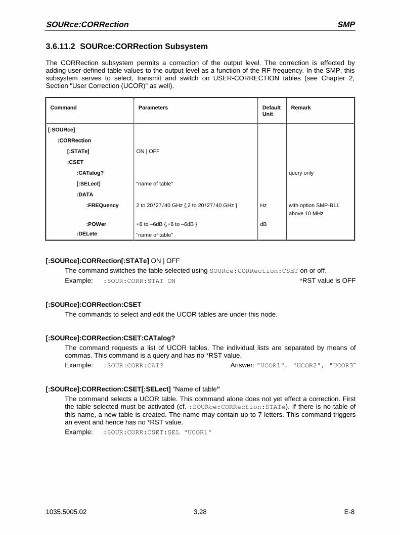
SOURce:CORRection SMP
1035.5005.02 3.28 E-8
3.6.11.2 SOURce:CORRection Subsystem
The CORRection subsystem permits a correction of the output level. The correction is effected byadding user-defined table values to the output level as a function of the RF frequency. In the SMP, thissubsystem serves to select, transmit and switch on USER-CORRECTION tables (see Chapter 2,Section "User Correction (UCOR)" as well).
Command Parameters DefaultUnit
Remark
[:SOURce]
:CORRection
[:STATe]
:CSET
:CATalog?
[:SELect]
:DATA
:FREQuency
:POWer
:DELete
ON | OFF
"name of table"
2 to 20/27/40 GHz ,2 to 20/27/40 GHz
+6 to –6dB ,+6 to –6dB
"name of table"
Hz
dB
query only
with option SMP-B11
above 10 MHz
[:SOURce]:CORRection[:STATe] ON | OFF
The command switches the table selected using SOURce:CORRection:CSET on or off.
Example: :SOUR:CORR:STAT ON *RST value is OFF
[:SOURce]:CORRection:CSETThe commands to select and edit the UCOR tables are under this node.
[:SOURce]:CORRection:CSET:CATalog?The command requests a list of UCOR tables. The individual lists are separated by means ofcommas. This command is a query and has no *RST value.
Example: :SOUR:CORR:CAT? Answer: "UCOR1", "UCOR2", "UCOR3"
[:SOURce]:CORRection:CSET[:SELect] "Name of table"The command selects a UCOR table. This command alone does not yet effect a correction. Firstthe table selected must be activated (cf. :SOURce:CORRection:STATe). If there is no table ofthis name, a new table is created. The name may contain up to 7 letters. This command triggersan event and hence has no *RST value.
Example: :SOUR:CORR:CSET:SEL "UCOR1"

SMP SOURce:CORRection
1035.5005.02 3.29 E-8
[:SOURce]:CORRection:CSET:DATAThe commands to edit the UCOR tables are under this node.
[:SOURce]:CORRection:CSET:DATA:FREQuency 2 to 20/27/40 GHz ,2 to 20/27/40 GHz (with option SMP-B11 above 10 MHz)
The command transmits the frequency data for the table selected using:SOURce:CORRection:CSET. The frequency values must be entered in ascending order. *RSTdoes not influence data lists.
Example: :SOUR:CORR:CSET:DATA:FREQ 100MHz,102MHz,103MHz,...
[:SOURce]:CORRection:CSET:DATA:POWer +6 to –6dB ,+6 to –6dB
The command transmits the level data for the table selected using:SOURce:CORRection:CSET. *RST does not influence data lists.
Example: :SOUR:CORR:CSET:DATA:POWer 1dB, 0.8dB, 0.75dB,...
[:SOURce]:CORRection:CSET:DELete "Name of table"
The command deletes the table indicated from the instrument memory. This command triggers anevent and hence has no *RST value.
Example: :SOUR:CORR:CSET:DEL "UCOR3"
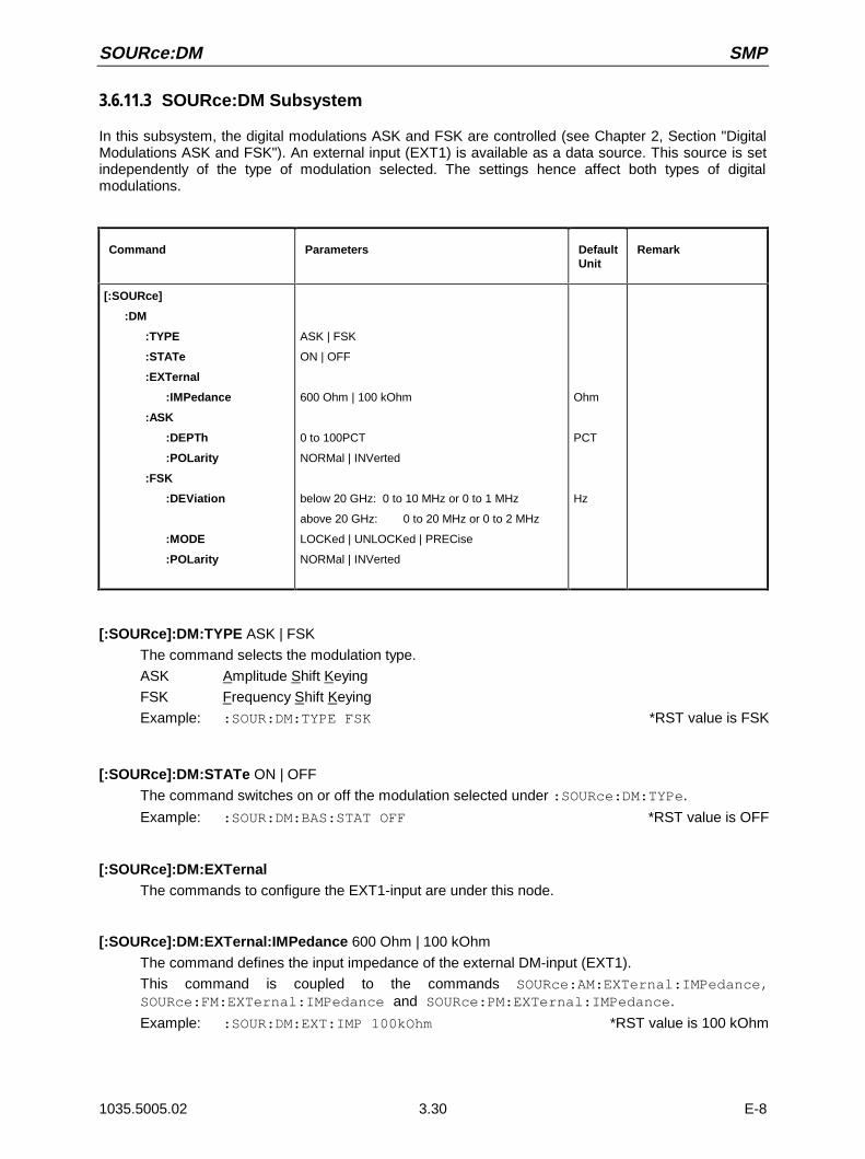
SOURce:DM SMP
1035.5005.02 3.30 E-8
3.6.11.3 SOURce:DM Subsystem
In this subsystem, the digital modulations ASK and FSK are controlled (see Chapter 2, Section "DigitalModulations ASK and FSK"). An external input (EXT1) is available as a data source. This source is setindependently of the type of modulation selected. The settings hence affect both types of digitalmodulations.
Command Parameters DefaultUnit
Remark
[:SOURce]
:DM
:TYPE
:STATe
:EXTernal
:IMPedance
:ASK
:DEPTh
:POLarity
:FSK
:DEViation
:MODE
:POLarity
ASK | FSK
ON | OFF
600 Ohm | 100 kOhm
0 to 100PCT
NORMal | INVerted
below 20 GHz: 0 to 10 MHz or 0 to 1 MHz
above 20 GHz: 0 to 20 MHz or 0 to 2 MHz
LOCKed | UNLOCKed | PRECise
NORMal | INVerted
Ohm
PCT
Hz
[:SOURce]:DM:TYPE ASK | FSK
The command selects the modulation type.
ASK Amplitude Shift Keying
FSK Frequency Shift Keying
Example: :SOUR:DM:TYPE FSK *RST value is FSK
[:SOURce]:DM:STATe ON | OFF
The command switches on or off the modulation selected under :SOURce:DM:TYPe.
Example: :SOUR:DM:BAS:STAT OFF *RST value is OFF
[:SOURce]:DM:EXTernalThe commands to configure the EXT1-input are under this node.
[:SOURce]:DM:EXTernal:IMPedance 600 Ohm | 100 kOhm
The command defines the input impedance of the external DM-input (EXT1).
This command is coupled to the commands SOURce:AM:EXTernal:IMPedance,SOURce:FM:EXTernal:IMPedance and SOURce:PM:EXTernal:IMPedance.
Example: :SOUR:DM:EXT:IMP 100kOhm *RST value is 100 kOhm
SMP SOURce:DM
1035.5005.02 3.31 E-8
[:SOURce]:DM:ASKThe commands to set the external data source for the digital amplitude modulation are under thisnode.
[:SOURce]:DM:ASK:DEPTh 0 to 100%
This command sets the modulation depth. *RST value is 10
Example: :SOUR:DM:ASK:DEPT 10
[:SOURce]:DM:ASK:POLarity NORMal | INVerted
The command defines the polarity of the modulation.
NORMal A "0" from the data source reduces the amplitude, a "1" increases it.
INVerted A "1" from the data source reduces the amplitude, a "0" increases it.
Example: :SOUR:DM:ASK:POL INV *RST value is NORMal
[:SOURce]:DM:FSKThe commands to set the data source for the digital frequency modulation are under this node.
[:SOURce]:DM:FSK:DEViation 0 to 1 MHz (FM/FSK-mode PRECise), 0 to 10 MHz (FM/FSK-mode LOCKed/UNLocked), SMP03/04 above 20 GHz: 0 to 2 MHz or 0 to 20 MHz
This command sets the frequency deviation of the FSK-modulation. The maximum deviationpossible depends on the FM/FSK mode set and – for SMP03/04 – also on the selected frequency(see FSK:MODE, Section "SOURce:FM-Subsystem" and Chapter 2, Section "FrequencyModulation").
Example: :SOUR:DM:FSK:DEV 3kHz *RST value is 10 kHz
[:SOURce]:DM:FSK:MODE UNLocked | LOCKed | PRECise
The command defines the FSK-modulation mode. It is coupled to the command SOUR:FM:MODE(see description of the command SOUR:FM:MODE in Section "SOURce:FM-Subsystem").
Example: :SOUR:DM:FSK:MODE UNL *RST value is LOCKed
[:SOURce]:DM:FSK:POLarity NORMal | INVerted
The command specifies the polarity of the modulation.
NORMal Logical "0" reduces the frequency, logical "1" increases it.
INVerted Logical "1" reduces the frequency, logical "0" increases it.
Example: :SOUR:DM:FSK:POL INV *RST value is NORMal
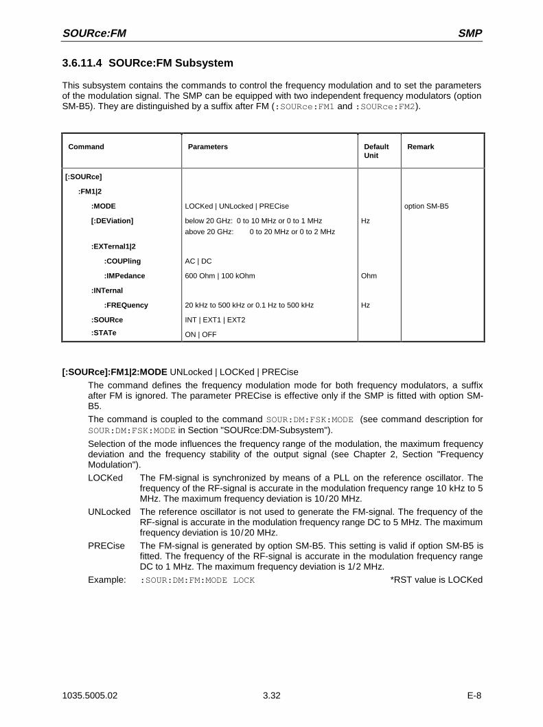
SOURce:FM SMP
1035.5005.02 3.32 E-8
3.6.11.4 SOURce:FM Subsystem
This subsystem contains the commands to control the frequency modulation and to set the parametersof the modulation signal. The SMP can be equipped with two independent frequency modulators (optionSM-B5). They are distinguished by a suffix after FM (:SOURce:FM1 and :SOURce:FM2).
Command Parameters DefaultUnit
Remark
[:SOURce]
:FM1|2
:MODE
[:DEViation]
:EXTernal1|2
:COUPling
:IMPedance
:INTernal
:FREQuency
:SOURce
:STATe
LOCKed | UNLocked | PRECise
below 20 GHz: 0 to 10 MHz or 0 to 1 MHz
above 20 GHz: 0 to 20 MHz or 0 to 2 MHz
AC | DC
600 Ohm | 100 kOhm
20 kHz to 500 kHz or 0.1 Hz to 500 kHz
INT | EXT1 | EXT2
ON | OFF
Hz
Ohm
Hz
option SM-B5
[:SOURce]:FM1|2:MODE UNLocked | LOCKed | PRECise
The command defines the frequency modulation mode for both frequency modulators, a suffixafter FM is ignored. The parameter PRECise is effective only if the SMP is fitted with option SM-B5.
The command is coupled to the command SOUR:DM:FSK:MODE (see command description forSOUR:DM:FSK:MODE in Section "SOURce:DM-Subsystem").
Selection of the mode influences the frequency range of the modulation, the maximum frequencydeviation and the frequency stability of the output signal (see Chapter 2, Section "FrequencyModulation").
LOCKed The FM-signal is synchronized by means of a PLL on the reference oscillator. Thefrequency of the RF-signal is accurate in the modulation frequency range 10 kHz to 5MHz. The maximum frequency deviation is 10/20 MHz.
UNLocked The reference oscillator is not used to generate the FM-signal. The frequency of theRF-signal is accurate in the modulation frequency range DC to 5 MHz. The maximumfrequency deviation is 10/20 MHz.
PRECise The FM-signal is generated by option SM-B5. This setting is valid if option SM-B5 isfitted. The frequency of the RF-signal is accurate in the modulation frequency rangeDC to 1 MHz. The maximum frequency deviation is 1/2 MHz.
Example: :SOUR:DM:FM:MODE LOCK *RST value is LOCKed

SMP SOURce:FM
1035.5005.02 3.33 E-8
[:SOURce]:FM1|2[:DEViation] 0 to 1 MHz or 0 to10 MHz; >20GHz 0 to 2 MHzor 0 to 20 MHz
The command specifies the frequency variation caused by the FM. Although the LF generatorsare used as modulation sources, the frequency variation is independent of the voltage at the LFoutput. The maximum possible DEViation depends on the selected FM-mode and for SMP03/04also on the selected frequency (SOURce:FREQuency).
LOCKed and UNLocked: f ≤ 20 GHz DEV MAX = 10 MHzf > 20 GHz DEV MAX = 20 MHz
PRECise: f ≤ 20 GHz DEV MAX = 1 MHzf > 20 GHz DEV MAX = 2 MHz
Example: :SOUR:FM1:DEV 5kHz *RST value is 10 kHz
[:SOURce]:FM1|2:EXTernal 2The commands to set the external FM input are under this node. The settings under EXTernal formodulations AM, FM and PM are independent of each other. The settings are always related tothe socket which is determined by the numeric suffix after EXTernal. The suffix after FM is ignoredthen. With the following commands, e.g., the settings are both related to EXT2 input::SOUR:FM1:EXT2:COUP AC
:SOUR:FM2:EXT2:COUP AC
A command without suffix is interpreted like a command with suffix 1.
[:SOURce]:FM1|2:EXTernal1|2:COUPling AC | DC
The command selects the type of coupling for the external FM input.
AC The d.c. voltage content is separated from the modulation signal.
DC The modulation signal is not altered. *RST value is AC
Example: :SOUR:FM:EXT:COUP AC
[:SOURce]:FM1|2:EXTernal1|2:IMPedance 600 Ohm | 100 kOhm
The command defines the input impedance of the external FM-input. This command is coupled tothe commands SOURce:AM:EXTernal:IMPedance, SOURce:DM:EXTernal:IMPedanceand SOURce:PM:EXTernal:IMPedance.
Example: :SOUR:FM:EXT:IMP 100kOhm *RST value is 100 kOhm
[:SOURce]:FM1|2:INTernalThe settings for the internal FM generators are effected under this node. For FM1, this is alwaysLF generator 1, for FM2, always LF generator 2. Here the same hardware is set for FM1, PM1,AM:INT1 as well as SOURce0, just like for FM2, PM2 and AM:INT2 as well as SOURce2. Thismeans that, e.g., the following commands are coupled to each other and have the same effect:SOUR:AM:INT2:FREQ
SOUR:FM2:INT:FREQ
SOUR:PM2:INT:FREQ
SOUR2:FREQ:CW

SOURce:FM SMP
1035.5005.02 3.34 E-8
[:SOURce]:FM1|2:INTernal:FREQuency 10 kHz/ DC to 5 MHz / DC to 1 MHz
The command sets the modulation frequency. Depending on the FM-mode selected, only aspecific range is permitted (see Chapter 2, Section "Frequency Modulation").
LOCKed FREQ = 10 kHz to 5 MHz
UNLocked FREQ = DC to 5 MHz
PRECise FREQ = DC Hz to 1 MHz
Example: :SOUR:FM:INT:FREQ 10kHz *RST value is 1 kHz
[:SOURce]:FM1|2:SOURce INTernal | EXTernal1 | EXTernal2
The command selects the modulation source. A command without suffix is interpreted like acommand with suffix 1. LF generator 1 is INT for FM1, LF generator 2 for FM2. An external andan internal modulation source can be specified at the same time (cf. example)
*RST value for FM1: INT
Example: :SOUR:FM:SOUR INT1, EXT2 for FM2:EXT2
[:SOURce]:FM1|2:STATe ON | OFF
The command switches the frequency modulation on or off. *RST value is OFF.
Example: SOUR:FM:STAT OFF

SMP SOURce:FREQuency
1035.5005.02 3.35 E-8
3.6.11.5 SOURce:FREQuency Subsystem
This subsystem contains the commands for the frequency settings of the RF source including thesweeps.
Command Parameters DefaultUnit
Remark
[:SOURce]
:FREQuency
:CENTer
[:CW|:FIXed]
:RCL
:MANual
:MODE
:MULTiplier
:OFFSet
:SPAN
:STARt
:STOP
:STEP
[:INCRement]
2 to 20/27/40 GHz
2 to 20/27/40 GHz
INCLude | EXCLude
2 to 20/27/40 GHz
CW | FIXed | SWEep | LIST
1.0 to 10.0
-50 to +50 GHz
0 to 18/25/38 GHz
2 to 20/27/40 GHz
2 to 20/27/40 GHz
0 to 10 GHz
Hz
Hz
Hz
Hz
Hz
Hz
Hz
Hz
with option SMP-B11
10 to 20/27/40 GHz
10 to 20/27/40 GHz
10 to 20/27/40 GHz
0 to 19.9/26.9/39.9 GHz
10 MHz to 20/27/40 GHz
10 MHz to 20/27/40 GHz
[:SOURce]:FREQuency:CENTer SMP02: 2 to 20 GHz, SMP03: 2 to 27 GHz, SMP04: 2 to 40 GHz
The command sets the sweep range by means of the center frequency. This command is coupledto the commands :SOURce:FREQuency:STARt and :SOURce:FREQuency:STOP.
Here – like for the input value FREQUENCY in the FREQUENCY menu – the OFFSET-value istaken into account. Thus the frequency range quoted is only valid for OFFSet = 0 and MULTiplier= 1. For other OFFSet and MULTiplier values, the range can be calculated according to thefollowing formula (cf. Chapter 2, Section "Frequency Offset" as well):
2 GHz x MULTiplier + OFFSet to 20/27/40 GHz x MULTiplier + OFFSet
Example: :SOUR:FREQ:CENT 10GHz *RST value is (STARt +STOP)/2
[:SOURce]:FREQuency[:CW | :FIXed] 2 to 20/27/40 GHz (with option SMP-B11: 10 MHz to 20/27/40 GHz)
The command sets the frequency for CW operation. This value is coupled to the current sweepfrequency. In addition to a numeric value, UP and DOWN can be indicated. The frequency isincreased or reduced by the value set under :SOURce:FREQuency:STEP. (As to specifiedrange, cf. FREQuency:CENTer).
Example: :SOUR:FREQ:CW 10GHz *RST value is 10 GHz
[:SOURce]:FREQuency[:CW|:FIXed]:RCL INCLude | EXCLude
The command determines the effect of the recall function on the frequency. *RST value has noeffect to this setting.INCLude The saved frequency is loaded when instrument settings are loaded with the
[RECALL] key or with a memory sequence.EXCLude The RF frequency is not loaded when instrument settings are loaded, the current
settings are maintained.Example: :SOUR:FREQ:RCL INCL

SOURce:FREQuency SMP
1035.5005.02 3.36 E-8
[:SOURce]:FREQuency:MANual 2 to 20/27/40 GHz (with option SMP-B11: 10 MHz to 20/27/ GHz)
The command sets the frequency if SOURce:SWEep:MODE MANual andSOURce:FREQuency:MODE SWEep are set. Only frequency values between the settings with:SOURce:FREQuency:STARt and :SOURce:FREQuency:STOP are permitted. (As to thepermitted range, cf. FREQuency:CENTer) *RST value is 10 GHz
Example: :SOUR:FREQ:MAN 5GHz
[:SOURce]:FREQuency:MODE CW | FIXed | SWEep | LIST
The command specifies the operating mode and hence also specifies which commands controlthe FREQuency subsystem. The parameters are assigned as follows:
CW |FIXed CW and FIXed are synonyms. The output frequency is specified by means of:SOURce:FREQuency:CW | FIXed.
SWEep The instrument operates in the SWEep-mode. The frequency is specified by meansof commands SOURce:FREQuency:STARt; STOP; CENTer; SPAN; MANual.
LIST The instrument processes a list of frequency and level settings. The settings areeffected in the SOURce:LIST subsystem. Setting SOURce :FREQuency:MODE LISTautomatically sets command SOURce:POWer :MODE to LIST as well.
Example: :SOUR:FREQ:MODE LIST *RST value is CW.
[:SOURce]:FREQuency:MULTiplier 1.0 to 10.0
The command is used to enter the multiplier of a possible frequency multiplier connected in series(see Chapter 2, Section "Frequency Offset and Multiplier"). If a multiplier or a frequency offsetvalue have been entered, the frequency entered using SOURce:FREQuency: ... is no longeridentical with the RF-output frequency. The following relation holds:
SOURce:FREQuency:... = RF-output frequency x MULTiplier + OFFset.
The entry of a multiplier does not change the RF-output frequency but only the value queried by[:SOURce]:FREQuency:..... *RST value is 1
Example: :SOUR:FREQ:MULT 2
[:SOURce]:FREQuency:OFFSet -50 to + 50 GHz
The command sets the frequency offset of an mixer which might be series-connected.(cf. above, :FREQuency:MULTiplier, and Chapter 2, Section "Frequency Offset andMultiplier").
Example: :SOUR:FREQ:OFFS 100MHz *RST value is 0
[:SOURce]:FREQuency:SPAN 2 to 18/25/38 GHz (with option SMP-B11: 0 to 19,9/26,9/39,9 GHz)
This command specifies the frequency range for the sweep. This parameter is coupled to the startand stop frequency. Negative values for SPAN are permitted, then STARt > STOP is true. Thefollowing relations hold:
STARt = CENTer – SPAN/2
STOP = CENTer + SPAN/2 *RST value is (STOP - STARt)
Example: :SOUR:FREQ:SPAN 10GHz

SMP SOURce:FREQuency
1035.5005.02 3.37 E-8
[:SOURce]:FREQuency:STARt 2 to 20/27/40 GHz (with option SMP-B11: 10 MHz to 20/27/40 GHz)
This command defines the starting value of the frequency for the sweep operation. ParametersSTARt, STOP, SPAN and CENTer are coupled to each other. STARt may be larger than STOP.(As to specified range, cf. FREQuency:CENTer). *RST value is 10 GHz
Example: :SOUR:FREQ:STAR 2GHz
[:SOURce]:FREQuency:STOP 2 to 20/27/40 GHz (with option SMP-B11: 10 MHz to 20/27/40 GHz)
This command indicates the final value of the frequency for the sweep operation (see STARt aswell). (As to the specified range, cf. FREQuency:CENTer). *RST value is 20 GHz
Example: :SOUR:FREQ:STOP 15GHz
[:SOURce]:FREQuency:STEPThe command to enter the step width for the frequency setting if frequency values UP or DOWNare used is under this node. This command is coupled to the KNOB STEP command in manualcontrol. Only linear step widths can be set.
[:SOURce]:FREQuency:STEP[:INCRement] 0 to 10 GHz
The command sets the step width for the frequency setting.
Example: :SOUR:FREQ:STEP:INCR 1MHz *RST value is 1MHz
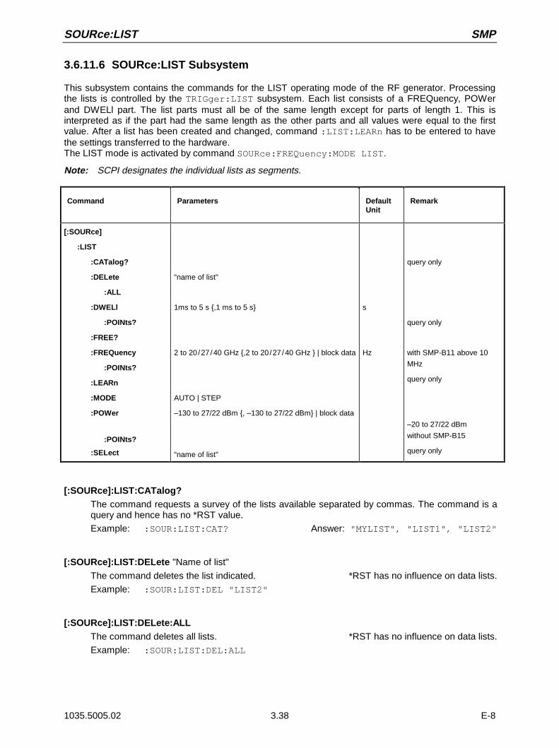
SOURce:LIST SMP
1035.5005.02 3.38 E-8
3.6.11.6 SOURce:LIST Subsystem
This subsystem contains the commands for the LIST operating mode of the RF generator. Processingthe lists is controlled by the TRIGger:LIST subsystem. Each list consists of a FREQuency, POWerand DWELl part. The list parts must all be of the same length except for parts of length 1. This isinterpreted as if the part had the same length as the other parts and all values were equal to the firstvalue. After a list has been created and changed, command :LIST:LEARn has to be entered to havethe settings transferred to the hardware.The LIST mode is activated by command SOURce:FREQuency:MODE LIST.
Note: SCPI designates the individual lists as segments.
Command Parameters DefaultUnit
Remark
[:SOURce]
:LIST
:CATalog?
:DELete
:ALL
:DWELl
:POINts?
:FREE?
:FREQuency
:POINts?
:LEARn
:MODE
:POWer
:POINts?
:SELect
"name of list"
1ms to 5 s ,1 ms to 5 s
2 to 20/27/40 GHz ,2 to 20/27/40 GHz | block data
AUTO | STEP
–130 to 27/22 dBm , –130 to 27/22 dBm | block data
"name of list"
s
Hz
query only
query only
with SMP-B11 above 10
MHz
query only
–20 to 27/22 dBm
without SMP-B15
query only
[:SOURce]:LIST:CATalog?The command requests a survey of the lists available separated by commas. The command is aquery and hence has no *RST value.
Example: :SOUR:LIST:CAT? Answer: "MYLIST", "LIST1", "LIST2"
[:SOURce]:LIST:DELete "Name of list"
The command deletes the list indicated. *RST has no influence on data lists.
Example: :SOUR:LIST:DEL "LIST2"
[:SOURce]:LIST:DELete:ALLThe command deletes all lists. *RST has no influence on data lists.
Example: :SOUR:LIST:DEL:ALL

SMP SOURce:LIST
1035.5005.02 3.39 E-8
[:SOURce]:LIST:DWELl 1 ms to 5 s , 1 ms to 5 s
For every item of the FREQuency or POWer/VOLTage list contents, the command specifies thetime the instrument "dwells" at this item.
Note: The RF generator is not in a position to allocate different times to the individual itemsof the FREQuency and POWer list contents. Thus the DWELl part of the list shouldhave length 1; the value is then valid for all items. If a list containing more than oneelement is indicated, all values must be equal.
Example: :SOUR:LIST:DWEL 0.15
[:SOURce]:LIST:DWELl:POINts?The command queries the length (in items) of the DWELl-part of the list. The command is a queryand thus has no *RST value.
Example: :SOUR:LIST:DWEL:POIN? Answer: 1
[:SOURce]:LIST:FREE?The command queries two values. The first one indicates the space still vacant for lists (in items),the second one the space already occupied, also in items. The command is a query and thus hasno *RST value.
Example: :SOUR:LIST:FREE? Answer: 2400, 200
[:SOURce]:LIST:FREQuency 2 to 20 27/40 GHz , 2 to 20 27/40GHz | block data (option SMP-B11: above 10 MHz)
The command fills the FREQuency part of the list selected with data. The data can either beindicated as a list of numbers (separated by commas) of arbitrary length or as binary block data.In the case of block data transmission, always 8 (4) bytes are interpreted as a floating-pointnumber of double accuracy (cf. command FORMat :DATA). *RST does not influence data lists.
Example: :SOUR:LIST:FREQ 14GHz, 13GHz, 12GHz, ...
[:SOURce]:LIST:FREQuency:POINts?The command queries the length (in items) of the FREQuency part of the list presently selected.The command is a query and thus has no *RST value.
Example: :SOUR:LIST:FREQ:POIN? Answer: 327
[:SOURce]:LIST:LEARnThe command learns the list selected. I.e., it determines the hardware setting for the entire list.The data thus determined are stored together with the list. The command triggers an event andthus has no *RST value.
Example: :SOUR:LIST:LEAR
Caution: This command has to be given after every creating and changing of a list.
[:SOURce]:LIST:MODE AUTO | STEP
The command indicates the mode in which the list is to be processed (by analogy withSOURce:SWEep:MODE).
AUTOEach trigger event triggers a complete list run.
STEP Each trigger event triggers only one step in processing the list.
Example: :SOUR:LIST:MODE STEP *RST value is AUTO

SOURce:LIST SMP
1035.5005.02 3.40 E-8
[:SOURce]:LIST:POWer -130 to 27 dBm , -130 to 27 dBm | block data (–20 to 27 dBm without option SMP-B15)
The command fills the POWer part of the RF list selected with data. The data can either beindicated as a list of numbers (separated by commas) of arbitrary length or as binary block data.As to the format of the data, cf. command :SOURce:LIST:FREQ. *RST does not influence datalists.
Example: :SOUR:LIST:POW 0dBm,-2dBm,-2dBm,-3dBm,...
[:SOURce]:LIST:POWer:POINts?The command queries the length (in items) of the LEVel part of the list presently selected. Thecommand is a query and thus has no *RST value
Example: :SOUR:LIST:POW:POIN? Answer: 327
[:SOURce]:LIST:SELect "Name of list"
The command selects the list indicated. If there is no list of this name, a new list is created. Thename may contain up to 7 letters. If the list does not exist yet, it is created. The command triggersan event and thus has no *RST value
Example: :SOUR:LIST:SEL "LIST1"

SMP SOURce:MARKer
1035.5005.02 3.41 E-8
3.6.11.7 SOURce:MARKer Subsystem
This subsystem contains the commands to control the generation of markers during the sweep. TheSMP has three markers each for frequency and level sweeps which are distinguished by a numericsuffix after MARKer. The settings for frequency sweep and level sweep marker are independent of eachother.
Command Parameters DefaultUnit
Remark
[:SOURce]
:MARKer 1 | 2 | 3
[:FSWeep]
:AMPLitude
:AOFF
:FREQuency
[:STATe]
:PSWeep
:AOFF
:POWer
[:STATe]
:POLarity
ON | OFF
2 to 20/27/40 GHz
ON | OFF
–130 dBm to 27/22 dBm
ON | OFF
NORMal | INVerted
Hz
dBm
no query
with option SMP-B11:above 10 MHz
no query
–20 dBm to 27/22 dBmwithout option SMP-B15
[:SOURce]:MARKer1|2|3[:FSWeep]The commands for the markers with frequency sweep are under this node. Keyword :FSWeepcan be omitted, then the command conforms to SCPI regulations.
[:SOURce]:MARKer1|2|3[:FSWeep]:AMPLitude ON | OFF
The command specifies whether the marker influences the signal level.
ON The output level is reduced by a constant value when the marker frequency isexecuted.
OFF The output level remains unchanged. *RST value is OFF
Example: :SOUR:MARK1:FSW:AMP ON
[:SOURce]:MARKer1|2|3[:FSWeep]:AOFFCommand (All markers off) switches off all frequency markers. This command triggers an event,thus it has no *RST value and no query form.
Example: :SOUR:MARK:FSW:AOFF
[:SOURce]:MARKer1|2|3[:FSWeep]:FREQuency 2 to 20/27/40 GHz
The command sets the marker selected by the numeric suffix with MARKer to the frequencyindicated.
Here – like for the input value MARKER in the SWEEP - FREQ menu – the OFFSET-values of theFREQuency subsystem are taken into account. Thus the specified range indicated is only valid forSOURce:FREQuency:OFFSet = 0, SOUR:FREQ:Mult = 1. The specified range for other OFFSetMultiplier values can be calculated according to the following formula (cf. Chapter 2, Section"Frequency Offset and Multiplier", as well):
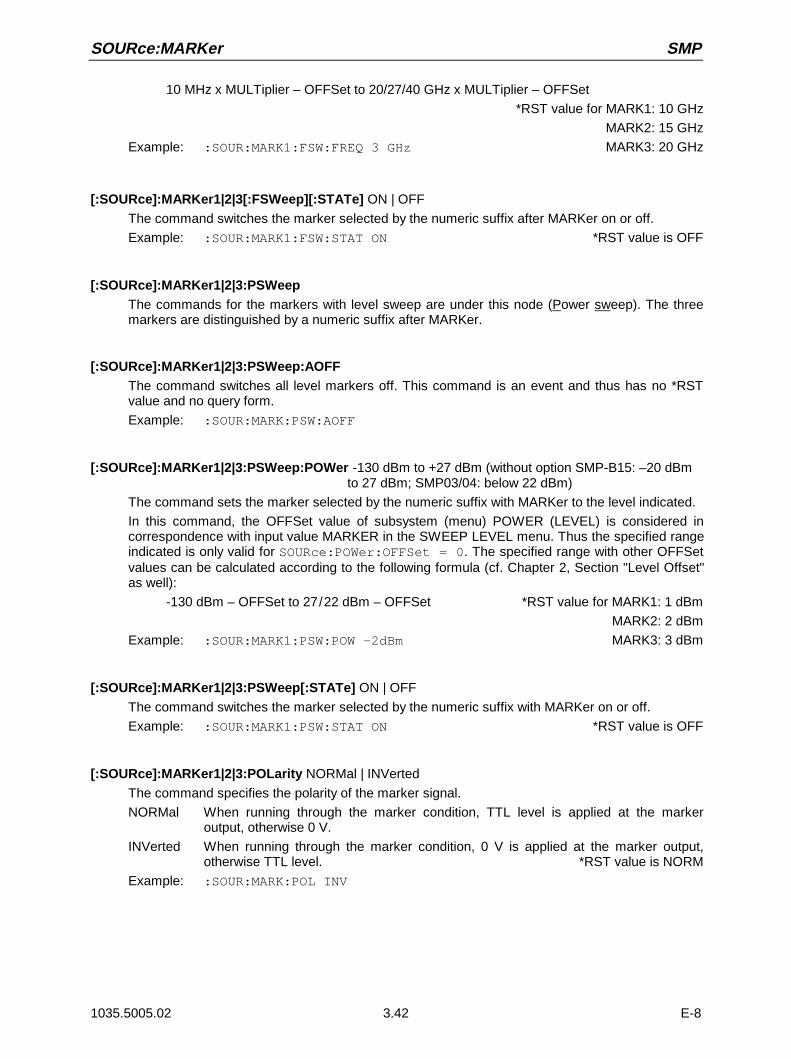
SOURce:MARKer SMP
1035.5005.02 3.42 E-8
10 MHz x MULTiplier – OFFSet to 20/27/40 GHz x MULTiplier – OFFSet
*RST value for MARK1: 10 GHz
MARK2: 15 GHz
Example: :SOUR:MARK1:FSW:FREQ 3 GHz MARK3: 20 GHz
[:SOURce]:MARKer1|2|3[:FSWeep][:STATe] ON | OFF
The command switches the marker selected by the numeric suffix after MARKer on or off.
Example: :SOUR:MARK1:FSW:STAT ON *RST value is OFF
[:SOURce]:MARKer1|2|3:PSWeepThe commands for the markers with level sweep are under this node (Power sweep). The threemarkers are distinguished by a numeric suffix after MARKer.
[:SOURce]:MARKer1|2|3:PSWeep:AOFFThe command switches all level markers off. This command is an event and thus has no *RSTvalue and no query form.
Example: :SOUR:MARK:PSW:AOFF
[:SOURce]:MARKer1|2|3:PSWeep:POWer -130 dBm to +27 dBm (without option SMP-B15: –20 dBm to 27 dBm; SMP03/04: below 22 dBm)
The command sets the marker selected by the numeric suffix with MARKer to the level indicated.
In this command, the OFFSet value of subsystem (menu) POWER (LEVEL) is considered incorrespondence with input value MARKER in the SWEEP LEVEL menu. Thus the specified rangeindicated is only valid for SOURce:POWer:OFFSet = 0. The specified range with other OFFSetvalues can be calculated according to the following formula (cf. Chapter 2, Section "Level Offset"as well):
-130 dBm – OFFSet to 27/22 dBm – OFFSet *RST value for MARK1: 1 dBm
MARK2: 2 dBm
Example: :SOUR:MARK1:PSW:POW –2dBm MARK3: 3 dBm
[:SOURce]:MARKer1|2|3:PSWeep[:STATe] ON | OFF
The command switches the marker selected by the numeric suffix with MARKer on or off.
Example: :SOUR:MARK1:PSW:STAT ON *RST value is OFF
[:SOURce]:MARKer1|2|3:POLarity NORMal | INVerted
The command specifies the polarity of the marker signal.
NORMal When running through the marker condition, TTL level is applied at the markeroutput, otherwise 0 V.
INVerted When running through the marker condition, 0 V is applied at the marker output,otherwise TTL level. *RST value is NORM
Example: :SOUR:MARK:POL INV

SMP SOURce:PHASe
1035.5005.02 3.43 E-8
3.6.11.8 SOURce:PHASe Subsystem
Command Parameters DefaultUnit
Remark
[:SOURce]
:PHASe
[:ADJust]
:REFerence
-360 deg to +360 deg rad
no query
[:SOURce]:PHASe[:ADJust] -360 deg to +360 deg
The command indicates the phase between output signal and reference oscillator signal. Thissetting is only accepted using SOURce:PHASe:REFerence (cf. below). An indication in RADianis possible.
Example: :SOUR:PHAS:ADJ 2DEG
:SOUR:PHAS:ADJ 0.1RAD *RST value is 0.0 DEG
[:SOURce]:PHASe:REFerenceThe command accepts the phase set using SOURce:PHASe:ADJust as a new reference phase.The command has no *RST value.
Example: :SOUR:PHAS:REF

SOURce:PM SMP
1035.5005.02 3.44 E-8
3.6.11.9 SOURce:PM Subsystem
This subsystem contains the commands to check the phase modulation and to set the parameters ofthe modulation signal. The SMP can be equipped with two independent phase modulators, PM1 andPM2 (option SM-B5). They are distinguished by a suffix after PM.
Command Parameters DefaultUnit
Remark
[:SOURce]
:PM 1 | 2
[:DEViation]
:EXTernal 1 | 2
:COUPling
:IMPedance
:INTernal
:FREQuency
:SOURce
:STATe
0 to 10/20 rad
AC | DC
600 Ohm | 100 kOhm
400 Hz | 1 kHz | 3 kHz | 15 kHz or
0.1Hz to 100 kHz
INT | EXT1 | EXT2
ON | OFF
rad
Ohm
Hz
option SM-B5
option SM-B2
[:SOURce]:PM1|2[:DEViation] 0 to 10 rad (SMP03/04 above 20 GHz: 0 to 20 rad)
The command sets the modulation deviation in Radian. DEGRee is accepted, too.
Example: SOUR:PM:DEV 20DEGR *RST value is 1 rad
[:SOURce]:PM1|2:EXTernal1|2The commands to check the external input of the PM modulators are under this node. Thesettings under EXTernal for modulations AM, FM and PM are independent of each other. Thesettings are always related to the socket determined by the suffix after EXTernal. The suffix afterPM is ignored then. With the following commands, e.g., the settings are both related to socketEXT2:
:SOUR:PM1:EXT2:COUP AC
:SOUR:PM2:EXT2:COUP AC
A command without suffix is interpreted like a command with suffix 1.
[:SOURce]:PM1|2:EXTernal1|2:COUPling AC | DC
The command selects the type of coupling for the external PM input.
AC The d.c. voltage content is separated from the modulation signal.
DC The modulation signal is not changed. *RST value is AC
Example: :SOUR:PM:COUP DC
[:SOURce]:PM 1|2:EXTernal1|2:IMPedance 600 Ohm | 100 kOhm
The command defines the input resistance of the selected external PM-input. This command iscoupled to the commands SOURce:AM:EXTernal:IMPedance,SOURce:DM:EXTernal:IMPedance and SOURce:FM:EXTernal:IMPedance.
Example: :SOUR:PM:IMP100kOhm *RST value is 100 kOhm

SMP SOURce:PM
1035.5005.02 3.45 E-8
[:SOURce]:PM1|2:INTernalThe settings for the internal PM generators are effected under this node. For PM1, this is alwaysLF generator 1, for PM2, always LF generator 2. Here the same hardware is set for FM1, PM1,AM::INT1 as well as SOURce0, for FM2, PM2 and AM:INT2 and SOURce2 as well. This meansthat, e.g., the following commands are coupled to each other and have the same effect:SOUR:AM:INT2:FREQ
SOUR:FM2:INT:FREQ
SOUR:PM2:INT:FREQ
SOUR2:FREQ:CW
[:SOURce]:PM1|2:INTernal:FREQuency 400 Hz | 1 kHz | 3 kHz | 15 kHz or 0.1 Hz to 100 kHz(option SM-B2)
The command sets the modulation frequency. There are different specified ranges depending onthe equipment of the instrument:
If SM-B2 is not fitted, only INT1 is permitted and values of 400 Hz, 1 kHz, 3 kHz and 15 kHz arevalid. With option SM-B2, the range from 0.1 Hz to 100 kHz is valid:
Example: :SOUR:PM:INT:FREQ 10kHz *RST value is 1 kHz
[:SOURce]:PM1|2:SOURce INTernal | EXTernal1 | EXTernal2
The command selects the modulation source. A command without suffix is interpreted like acommand with suffix 1. INTernal means LF generator 1 for PM1, LF generator2 for PM2. Severalmodulation sources can be active at the same time (see example)
*RST value for PM1: INT
Example: :SOUR:PM:SOUR INT, EXT2 for PM2:EXT2
[:SOURce]:PM1|2:STATe ON | OFF
The command switches the phase modulation selected by the numeric suffix with PM on or off.
Example: :SOUR:PM1:STAT OFF *RST value is OFF

SOURce:POWer SMP
1035.5005.02 3.46 E-8
3.6.11.10 SOURce:POWer Subsystem
This subsystem contains the commands to set the output level, the level control and the level correctionof the RF signal. Other units can be used instead of dBm:
• by indication directly after the numeric value (example :POW 0.5V),
• by altering the DEFault unit in the UNIT system (see Command :UNIT:POWER)
Command Parameters DefaultUnit
Remark
[:SOURce]
:POWer
:ALC
:REFerence
:SEARch
:SOURce
:PMETer
[:STATe]
[:LEVel]
[:IMMediate]
[AMPLitude]
:OFFSet
:RCL
:LIMit
[:AMPLitude]
:MANual
:MODE
:STARt
:STOP
:STEP
[:INCRement]
0 to 3 V
ON | OFF | ONCE
INTernal | DIODe | PMETer
RS_NRVS | HP436A
ON | OFF
–130 dBm to 27/22 dBm
-100 to +100 dB
INCLude | EXCLude
–130 dBm to 27/22 dBm
–130 dBm to 27/22 dBm
FIXed | SWEep | LIST
–130 dBm to 27/22 dBm
–130 dBm to 27/22 dBm
0.1 to 10 dB
dBm
dB
dBm
dBm
dBm
dBm
dB
Without option SMP-B15 the value range forthe level settingsAMPLitude, LIMit,MANual, STARt andSTOP is –20 dBm to+27/22 dBm
[:SOURce]:POWer:ALCThe commands checking the automatic level control are under this node.
[:SOURce]:POWer:ALC:REFerence 0 to 3 V
The command sets the reference voltage at the EXT-ALC-input . This command is suitable only ifeither DIOde or PMETer, TYPE HP436A are specified as a SOURce.
Example: :SOUR:POW:ALC:REF 1 *RST value is 1 V
[:SOURce]:POWer:ALC:SEArch ON | OFF | ONCE
This command defines under which conditions the control loop is temporarily closed. Thecommand is suitable only if SOURce:ALC:STATe is set to OFF.
ON The control loop is closed each time the output level or the frequency is changed,otherwise, it remains open.
OFF The control loop is never closed.
ONCE The control loop is immediately closed for a short period and opened again. Then,SEARch is automatically set to off.
Example: :SOUR:POW:ALC:SEAR ON *RST value is OFF
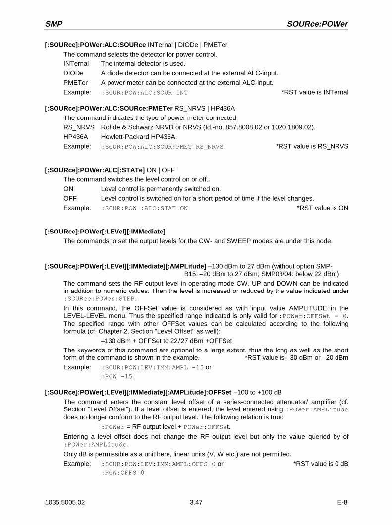
SMP SOURce:POWer
1035.5005.02 3.47 E-8
[:SOURce]:POWer:ALC:SOURce INTernal | DIODe | PMETer
The command selects the detector for power control.
INTernal The internal detector is used.
DIODe A diode detector can be connected at the external ALC-input.
PMETer A power meter can be connected at the external ALC-input.
Example: :SOUR:POW:ALC:SOUR INT *RST value is INTernal
[:SOURce]:POWer:ALC:SOURce:PMETer RS_NRVS | HP436A
The command indicates the type of power meter connected.
RS_NRVS Rohde & Schwarz NRVD or NRVS (Id.-no. 857.8008.02 or 1020.1809.02).
HP436A Hewlett-Packard HP436A.
Example: :SOUR:POW:ALC:SOUR:PMET RS_NRVS *RST value is RS_NRVS
[:SOURce]:POWer:ALC[:STATe] ON | OFF
The command switches the level control on or off.
ON Level control is permanently switched on.
OFF Level control is switched on for a short period of time if the level changes.
Example: :SOUR:POW :ALC:STAT ON *RST value is ON
[:SOURce]:POWer[:LEVel][:IMMediate]The commands to set the output levels for the CW- and SWEEP modes are under this node.
[:SOURce]:POWer[:LEVel][:IMMediate][:AMPLitude] –130 dBm to 27 dBm (without option SMP- B15: –20 dBm to 27 dBm; SMP03/04: below 22 dBm)
The command sets the RF output level in operating mode CW. UP and DOWN can be indicatedin addition to numeric values. Then the level is increased or reduced by the value indicated under:SOURce:POWer:STEP.
In this command, the OFFSet value is considered as with input value AMPLITUDE in theLEVEL-LEVEL menu. Thus the specified range indicated is only valid for :POWer:OFFSet = 0.The specified range with other OFFSet values can be calculated according to the followingformula (cf. Chapter 2, Section "Level Offset" as well):
–130 dBm + OFFSet to 22/27 dBm +OFFSet
The keywords of this command are optional to a large extent, thus the long as well as the shortform of the command is shown in the example. *RST value is –30 dBm or –20 dBm
Example: :SOUR:POW:LEV:IMM:AMPL –15 or:POW –15
[:SOURce]:POWer[:LEVel][:IMMediate][:AMPLitude]:OFFSet –100 to +100 dB
The command enters the constant level offset of a series-connected attenuator/ amplifier (cf.Section "Level Offset"). If a level offset is entered, the level entered using :POWer:AMPLitudedoes no longer conform to the RF output level. The following relation is true:
:POWer = RF output level + POWer:OFFSet.
Entering a level offset does not change the RF output level but only the value queried by of:POWer:AMPLitude.
Only dB is permissible as a unit here, linear units (V, W etc.) are not permitted.
Example: :SOUR:POW:LEV:IMM:AMPL:OFFS 0 or *RST value is 0 dB:POW:OFFS 0
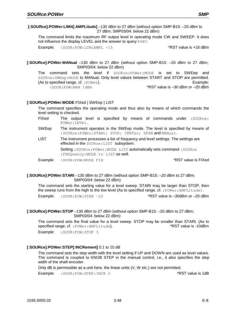
SOURce:POWer SMP
1035.5005.02 3.48 E-8
[:SOURce]:POWer:LIMit[:AMPLitude] –130 dBm to 27 dBm (without option SMP-B15: –20 dBm to 27 dBm; SMP03/04: below 22 dBm)
The command limits the maximum RF output level in operating mode CW and SWEEP. It doesnot influence the display LEVEL and the answer to query POW?.
Example: :SOUR:POW:LIM:AMPL –15 *RST value is +16 dBm
[:SOURce]:POWer:MANual –130 dBm to 27 dBm (without option SMP-B15: –20 dBm to 27 dBm; SMP03/04: below 22 dBm)
The command sets the level if SOURce:POWer:MODE is set to SWEep andSOURce:SWEep:MODE to MANual. Only level values between START and STOP are permitted.(As to specified range, cf. :POWer). Example:
:SOUR:POW:MAN 1dBm *RST value is –30 dBm or –20 dBm
[:SOURce]:POWer:MODE FIXed | SWEep | LIST
The command specifies the operating mode and thus also by means of which commands thelevel setting is checked.
FIXed The output level is specified by means of commands under :SOURce:POWer:LEVel.
SWEep The instrument operates in the SWEep mode. The level is specified by means of:SOURce:POWer;STARt; STOP; CENTer; SPAN and MANual.
LIST The instrument processes a list of frequency and level settings. The settings areeffected in the SOURce:LIST subsystem.
Setting :SOURce:POWer:MODE LIST automatically sets command :SOURce:FREQuency:MODE to LIST as well.
Example: :SOUR:POW:MODE FIX *RST value is FIXed
[:SOURce]:POWer:STARt –130 dBm to 27 dBm (without option SMP-B15: –20 dBm to 27 dBm; SMP03/04: below 22 dBm)
The command sets the starting value for a level sweep. STARt may be larger than STOP, thenthe sweep runs from the high to the low level (As to specified range, cf. :POWer:AMPLitude).
Example: :SOUR:POW:STAR -20 *RST value is –30dBm or –20 dBm
[:SOURce]:POWer:STOP –130 dBm to 27 dBm (without option SMP-B15: –20 dBm to 27 dBm; SMP03/04: below 22 dBm)
The command sets the final value for a level sweep. STOP may be smaller than STARt. (As tospecified range, cf. :POWer:AMPLitude). *RST value is -10dBm
Example: :SOUR:POW:STOP 3
[:SOURce]:POWer:STEP[:INCRement] 0.1 to 10 dB
The command sets the step width with the level setting if UP and DOWN are used as level values.The command is coupled to KNOB STEP in the manual control, i.e., it also specifies the stepwidth of the shaft encoder.
Only dB is permissible as a unit here, the linear units (V, W etc.) are not permitted.
Example: :SOUR:POW:STEP:INCR 2 *RST value is 1dB

SMP SOURce:PULM
1035.5005.02 3.49 E-8
3.6.11.11 SOURce:PULM Subsystem
This subsystem contains the commands to control the pulse modulation and to set the parameters ofthe modulation signal. The internal pulse generator (option SM-B4) is set in the SOURce:PULSesubsystem.
Command Parameters DefaultUnit
Remark
[:SOURce]
:PULM
EXTernal
:IMPedance
:INTernal
:FREQuency
:POLarity
:SOURce
:STATe
50 Ohm | 10 kOhm
0.01176 Hz to 10 MHz
NORMal | INVerted
INTernal | EXTernal
ON | OFF
Ohm
Hz
option SMP-B14
option SMP-B14
option SMP-B14
[:SOURce]:PULM:EXTernalThis note contains the commands controlling the input socket of the external pulse generator.
[:SOURce]:PULM:EXTernal:IMPedance 50 Ohm | 10 kOhm
The command sets the impedance of the input socket for the external pulse generator. The pulsegenerator has an own input socket, hence this setting is independent of the correspondingsettings under PM and FM.
Example: :SOUR:PULM:EXT:IMP 10E3 *RST value is 10 kOhm
[:SOURce]:PULM:INTernalThis note contains the commands controlling the internal modulation source.
[:SOURce]:PULM:INTernal:FREQuency 0.01176 Hz to 10 MHz
The command sets the frequency of the pulse generator. This parameter is coupled toSOURce:PULSe:PERiod.
Example: :SOUR:PULM:INT:FREQ 1MHz *RST value is 100 kHz
[:SOURce]:PULM:POLarity NORMal | INVerted
The command specifies the polarity between modulating and modulated signal.
NORMal The RF signal is suppressed during the interpulse period.
INVerted The RF signal is suppressed during the pulse.
Example: :SOUR:PULM:POL INV *RST value is NORMal

SOURce:PULM SMP
1035.5005.02 3.50 E-8
[:SOURce]:PULM:SOURce EXTernal | INTernal
The command selects the source of the modulating signal.
INTernal Internal pulse generator (option SM-B4).
EXTernal Signal fed externally
Example: :SOUR:PULM:SOUR INT *RST value is INTernal
[:SOURce]:PULM:STATe ON | OFF
The command switches on or off the pulse modulation. *RST value is OFF
Example: :SOUR:PULM:STAT ON

SMP SOURce:REFLex25
1035.5005.02 3.51 E-8
3.6.11.12 SOURce:PULSe Subsystem
This subsystem contains the commands to set the pulse generator (option SM-B4). The pulsegeneration is triggered on principle, with the trigger certainly being able to be set to "free run" usingTRIGger:PULSe:SOURce AUTO as well. The pulse modulation (option SM-B3) is set in theSOURce:PULM subsystem.
Command Parameters Default Unit Remark
[:SOURce]
:PULSe
:DELay
:DOUBle
:DELay
[:STATe]
:PERiod
:WIDTh
40 ns to 1 s
60 ns to 1 s
ON | OFF
100 ns to 85 s
20 ns to 1 s
s
s
s
s
option SMP-B4
[:SOURce]:PULSe:DELay 40 ns to 1 s
The command specifies the time from the start of the period to the first edge of the pulse. Due tothe construction of the instrument, this parameter is set to 0 if :SOURce:PULSe:DOUBle:STATeis set to ON. The old value is activated again as soon as the double pulse has been switched off.
Example: :SOUR:PULS:DEL 10us *RST value is 1 us
[:SOURce]:PULSe:DOUBleThe commands to check the second pulse are under this node. If :SOURce:PULSe:DOUBle:STATe is set to ON, a second pulse whose width is identical to the first pulse isgenerated in every period.
[:SOURce]:PULSe:DOUBle:DELay 60 ns to 1 s
The command sets the delay timee from the start of the pulse period to the first edge of thesecond pulse. *RST value is 1 us
Example: :SOUR:PULS:DOUB:DEL 10us
[:SOURce]:PULSe:DOUBle[:STATe] ON | OFF
The command switches the second pulse on or off.ON The second pulse is switched on. Parameter :SOURce:PULSe:DELay is set to 0
and cannot be changed. WIDTh > (PULSe:PERiod - PULSe:DOUBle:DELay)/2results in error message -221, "Settings conflict".
OFF The second pulse is switched off. *RST value is OFF
Example: :SOUR:PULS:DOUB:STAT OFF
[:SOURce]:PULSe:PERiod 100 ns to 85 s
The command sets the pulse period.The pulse period is the reciprocal value of the pulse frequency, thus this command is coupled tocommand :SOURce:PULM:INTernal:FREQuency *RST value is 10 us
Example: :SOUR:PULS:PER 2s
[:SOURce]:PULSe:WIDTh 20 ns to 1s
The command sets the pulse width. *RST value is 1 us
Example: :SOUR:PULS:WIDT 0.1s

SOURce:ROSCillator SMP
1035.5005.02 3.52 E-8
3.6.11.13 SOURce:ROSCillator Subsystem
This subsystem contains the commands to set the external and internal reference oscillator.
Command Parameters DefaultUnit
Remark
[:SOURce]
:ROSCillator
:EXTernal
:FREQuency
[:INTernal]
:ADJust
[:STATe]
:VALue
:SOURce
1 to 16 MHz
ON | OFF
0 to 4095
INTernal | EXTernal
Hz
[:SOURce]:ROSCillator:EXTernalThe commands to set the external reference oscillator are under this node.
[:SOURce]:ROSCillator:EXTernal:FREQuency 1 to 16 MHz
The command informs the instrument about at which frequency the external reference oscillatoroscillates.
Example: :SOUR:ROSC:FREQ 5MHz *RST value is 10 MHz
[:SOURce]:ROSCillator[:INTernal]:ADJustThe commands for frequency adjustment (fine-tuning of the frequency) are under this node.
[:SOURce]:ROSCillator[:INTernal]:ADJust[:STATe] ON | OFF
The command switches the frequency adjustment on or off.
Example: :SOUR:ROSC:INT:ADJ:STAT ON *RST value is OFF
[:SOURce]:ROSCillator[:INTernal]:ADJust:VALue 0 to 4095
The command indicates the frequency correction value (tuning value). For a detailed definition, cf.Chapter 2,Section "Reference Frequency Internal/External".
Example: :SOUR:ROSC:INT:ADJ:VAL 2048 *RST value is 2048
[:SOURce]:ROSCillator:SOURce INTernal | EXTernal
The command selects the reference source.
INTernal The internal oscillator is used.
EXTernal The reference signal is fed externally. *RST value is INTernal
Example: :SOUR:ROSC:SOUR EXT

SMP SOURce:SWEep
1035.5005.02 3.53 E-8
3.6.11.14 SOURce:SWEep Subsystem
This subsystem contains the commands to control the RF sweep, i.e., sweeps of the RF generators.Sweeps are triggered on principle. The frequency sweep is activated by commandSOURce:FREQuency:MODE SWEep, the level sweep by command SOURce:POWer:MODE SWEep.
Command Parameters DefaultUnit
Remark
[:SOURce]
:SWEep
:BTIMe
[:FREQuency]
:DWELl
:MODE
:POINts
:SPACing
:STEP
[:LINear]
:LOGarithmic
:POWer
:DWELl
:MODE
:POINts
:SPACing
:STEP
:LOGarithmic
NORMal | LONG
10 ms to 5 s
AUTO | MANual | STEP
number
Linear | Logarithmic
0 to 10 GHz
0.01 to 50 PCT
10 ms to 5 s
AUTO | MANual | STEP
number
Logarithmic
0 to 10 dB
s
Hz
PCT
s
dB
[:SOURce]:SWEep:BTIMe NORMal | LONG
The command sets the blank time of the sweep. The setting is valid for all sweeps, i.e., also for LFsweeps.
NORMal Blank time as short as possible.
LONG Blank time long enough to permit an XY recorder to return to 0.
Example: :SOUR:SWE:BTIM LONG *RST value is NORM
[:SOURce]:SWEep[:FREQuency]The commands to set the frequency sweeps are under this node. Keyword [:FREQuency] canbe omitted (cf. examples). The commands are SCPI compatible then unless stated otherwise.
[:SOURce]:SWEep[:FREQuency]:DWELl 10 ms to 5 s
The command sets the dwell time per frequency step.
Example: :SOUR:SWE:DWEL 12ms *RST value is 15 ms
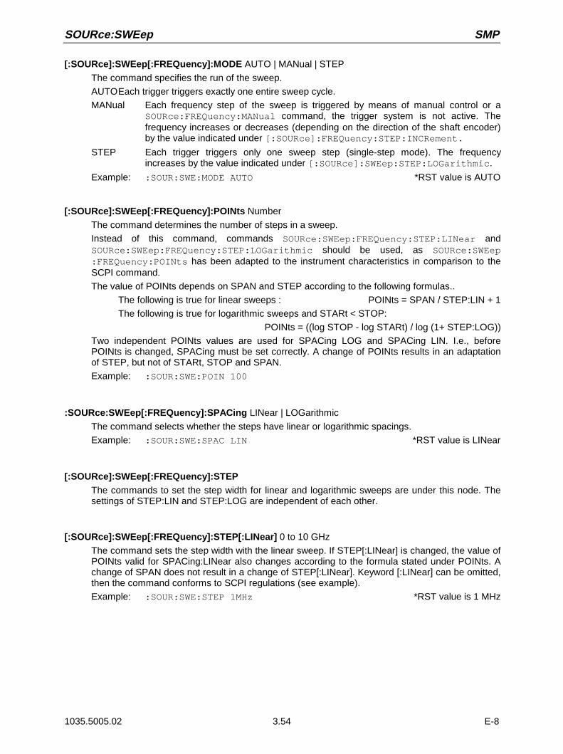
SOURce:SWEep SMP
1035.5005.02 3.54 E-8
[:SOURce]:SWEep[:FREQuency]:MODE AUTO | MANual | STEP
The command specifies the run of the sweep.
AUTOEach trigger triggers exactly one entire sweep cycle.
MANual Each frequency step of the sweep is triggered by means of manual control or aSOURce:FREQuency:MANual command, the trigger system is not active. Thefrequency increases or decreases (depending on the direction of the shaft encoder)by the value indicated under [:SOURce]:FREQuency:STEP:INCRement.
STEP Each trigger triggers only one sweep step (single-step mode). The frequencyincreases by the value indicated under [:SOURce]:SWEep:STEP:LOGarithmic.
Example: :SOUR:SWE:MODE AUTO *RST value is AUTO
[:SOURce]:SWEep[:FREQuency]:POINts Number
The command determines the number of steps in a sweep.
Instead of this command, commands SOURce:SWEep:FREQuency:STEP:LINear andSOURce:SWEep:FREQuency:STEP:LOGarithmic should be used, as SOURce:SWEep:FREQuency:POINts has been adapted to the instrument characteristics in comparison to theSCPI command.
The value of POINts depends on SPAN and STEP according to the following formulas..
The following is true for linear sweeps : POINts = SPAN / STEP:LIN + 1
The following is true for logarithmic sweeps and STARt < STOP:
POINts = ((log STOP - log STARt) / log (1+ STEP:LOG))
Two independent POINts values are used for SPACing LOG and SPACing LIN. I.e., beforePOINts is changed, SPACing must be set correctly. A change of POINts results in an adaptationof STEP, but not of STARt, STOP and SPAN.
Example: :SOUR:SWE:POIN 100
:SOURce:SWEep[:FREQuency]:SPACing LINear | LOGarithmic
The command selects whether the steps have linear or logarithmic spacings.
Example: :SOUR:SWE:SPAC LIN *RST value is LINear
[:SOURce]:SWEep[:FREQuency]:STEPThe commands to set the step width for linear and logarithmic sweeps are under this node. Thesettings of STEP:LIN and STEP:LOG are independent of each other.
[:SOURce]:SWEep[:FREQuency]:STEP[:LINear] 0 to 10 GHz
The command sets the step width with the linear sweep. If STEP[:LINear] is changed, the value ofPOINts valid for SPACing:LINear also changes according to the formula stated under POINts. Achange of SPAN does not result in a change of STEP[:LINear]. Keyword [:LINear] can be omitted,then the command conforms to SCPI regulations (see example).
Example: :SOUR:SWE:STEP 1MHz *RST value is 1 MHz
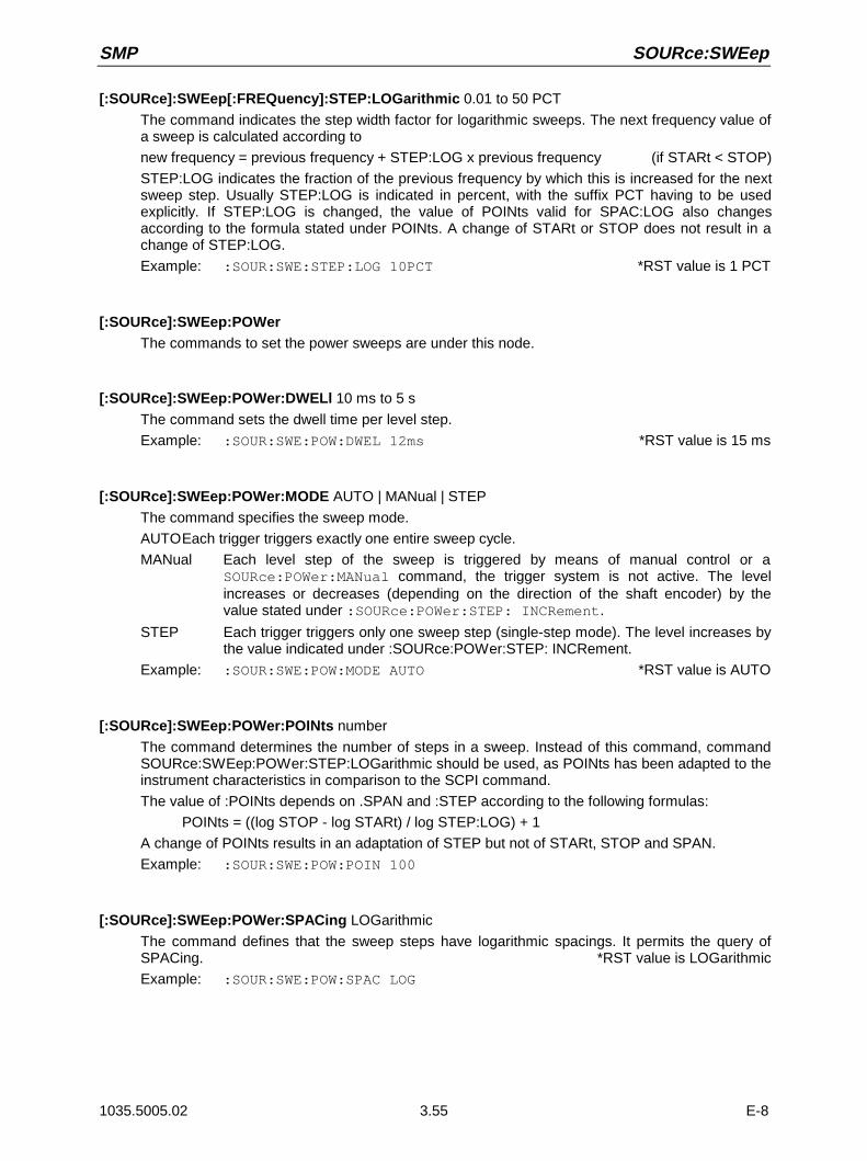
SMP SOURce:SWEep
1035.5005.02 3.55 E-8
[:SOURce]:SWEep[:FREQuency]:STEP:LOGarithmic 0.01 to 50 PCT
The command indicates the step width factor for logarithmic sweeps. The next frequency value ofa sweep is calculated according to
new frequency = previous frequency + STEP:LOG x previous frequency (if STARt < STOP)
STEP:LOG indicates the fraction of the previous frequency by which this is increased for the nextsweep step. Usually STEP:LOG is indicated in percent, with the suffix PCT having to be usedexplicitly. If STEP:LOG is changed, the value of POINts valid for SPAC:LOG also changesaccording to the formula stated under POINts. A change of STARt or STOP does not result in achange of STEP:LOG.
Example: :SOUR:SWE:STEP:LOG 10PCT *RST value is 1 PCT
[:SOURce]:SWEep:POWerThe commands to set the power sweeps are under this node.
[:SOURce]:SWEep:POWer:DWELl 10 ms to 5 s
The command sets the dwell time per level step.
Example: :SOUR:SWE:POW:DWEL 12ms *RST value is 15 ms
[:SOURce]:SWEep:POWer:MODE AUTO | MANual | STEP
The command specifies the sweep mode.
AUTOEach trigger triggers exactly one entire sweep cycle.
MANual Each level step of the sweep is triggered by means of manual control or aSOURce:POWer:MANual command, the trigger system is not active. The levelincreases or decreases (depending on the direction of the shaft encoder) by thevalue stated under :SOURce:POWer:STEP: INCRement.
STEP Each trigger triggers only one sweep step (single-step mode). The level increases bythe value indicated under :SOURce:POWer:STEP: INCRement.
Example: :SOUR:SWE:POW:MODE AUTO *RST value is AUTO
[:SOURce]:SWEep:POWer:POINts number
The command determines the number of steps in a sweep. Instead of this command, commandSOURce:SWEep:POWer:STEP:LOGarithmic should be used, as POINts has been adapted to theinstrument characteristics in comparison to the SCPI command.
The value of :POINts depends on .SPAN and :STEP according to the following formulas:
POINts = ((log STOP - log STARt) / log STEP:LOG) + 1
A change of POINts results in an adaptation of STEP but not of STARt, STOP and SPAN.
Example: :SOUR:SWE:POW:POIN 100
[:SOURce]:SWEep:POWer:SPACing LOGarithmic
The command defines that the sweep steps have logarithmic spacings. It permits the query ofSPACing. *RST value is LOGarithmic
Example: :SOUR:SWE:POW:SPAC LOG

SOURce:SWEep SMP
1035.5005.02 3.56 E-8
[:SOURce]:SWEep:POWer:STEPThe commands to set the step width for the sweep are under this node.
[:SOURce]:SWEep:POWer:STEP:LOGarithmic 0 to 10 dB
The command indicates the step width factor for logarithmic sweeps. The next level value of asweep is calculated according to
new level = previous level + STEP:LOG × previous level
STEP:LOG denotes the fraction of the previous level by which this is increased for the next sweepstep. Usually STEP:LOG is entered in units of dB, with suffix dB having to be specified explicitly. IfSTEP:LOG is changed, the value of POINts also changes according to the formula indicatedunder POINts. A change of STARt or STOP does not result in a change of STEP:LOG. Keyword:LOG can be omitted, then the command conforms to SCPI regulation (see example).
Example: :SOUR:SWE:STEP 10dB *RST value is 1dB
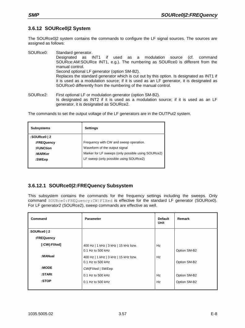
SMP SOURce0|2:FREQuency
1035.5005.02 3.57 E-8
3.6.12 SOURce0|2 System
The SOURce0|2 system contains the commands to configure the LF signal sources. The sources areassigned as follows:
SOURce0: Standard generator.Designated as INT1 if used as a modulation source (cf. commandSOURce:AM:SOURce INT1, e.g.). The numbering as SOURce0 is different from themanual control.Second optional LF generator (option SM-B2).Replaces the standard generator which is cut out by this option. Is designated as INT1 ifit is used as a modulation source; if it is used as an LF generator, it is designated asSOURce0 differently from the numbering of the manual control.
SOURce2: First optional LF or modulation generator (option SM-B2).Is designated as INT2 if it is used as a modulation source; if it is used as an LFgenerator, it is designated as SOURce2.
The commands to set the output voltage of the LF generators are in the OUTPut2 system.
Subsystems Settings
:SOURce0 | 2
:FREQuency
:FUNCtion
:MARKer
:SWEep
Frequency with CW and sweep operation.
Waveform of the output signal
Marker for LF sweeps (only possible using SOURce2)
LF sweep (only possible using SOURce2)
3.6.12.1 SOURce0|2:FREQuency Subsystem
This subsystem contains the commands for the frequency settings including the sweeps. Onlycommand SOURce0:FREQuency:CW|FIXed is effective for the standard LF generator (SOURce0).For LF generator2 (SOURce2), sweep commands are effective as well.
Command Parameter DefaultUnit
Remark
:SOURce0 | 2
:FREQuency
[:CW|:FIXed]
:MANual
:MODE
:STARt
:STOP
400 Hz | 1 kHz | 3 kHz | 15 kHz bzw.
0.1 Hz to 500 kHz
400 Hz | 1 kHz | 3 kHz | 15 kHz bzw.
0.1 Hz to 500 kHz
CW|FIXed | SWEep
0.1 Hz to 500 kHz
0.1 Hz to 500 kHz
Hz
Hz
Hz
Hz
Option SM-B2
Option SM-B2
Option SM-B2
Option SM-B2

SOURce0|2:FREQuency SMP
1035.5005.02 3.58 E-8
:SOURce0|2:FREQuency[:CW | :FIXed] 400 Hz | 1 kHz | 3 kHz | 15 kHz bzw. 0.1 Hz to 500 kHz(Option SM-B2)
The command sets the frequency for the CW mode.
If SM-B2 is not fitted, the values 400 Hz, 1 kHz, 3 kHz and 15 kHz are permissible for INT1. Withoption SM-B2, values from 0.1 Hz to 500 kHz are permissible.
Beispiel: :SOUR2:FREQ:CW 1kHz RST-Wert ist 1 kHz
:SOURce0|2:FREQuency:MANual 400 Hz | 1 kHz | 3 kHz | 15 kHz bzw. 0.1 Hz to 500 kHz (Option SM-B2)
The command sets the frequency if SOURce2:SWEep:MODe MANual and SOURce2:FREQuency: MODe SWEep are set. In this case, only frequency values between the settingsSOURce2: FREQuency:STARt and to :STOP are allowed.
Example: :SOUR2:FREQ:MAN 1kHz *RST value is 1kHz
SOURce0|2:FREQuency:MODE CW|FIXed | SWEep
The command specifies the operating mode and hence by means of which commands theFREQuency subsystem is controled. The following allocations are valid:
CW |FIXed CW and FIXed are synonyms. The output frequency is specified by means ofSOURce0|2:FREQuency:CW |FIXed.
SWEep The generator operates in the SWEep mode. The frequency is specified by meansof commands SOURce2:FREQuency:STARt; STOP; MANual. The SWEepsetting is only possible for SOURce2-
Example: :SOUR2:FREQ:MODE CW *RST value is CW
:SOURce0|2:FREQuency:STARt 0.1 Hz to 500 kHz
This command defines the starting value of the frequency for the sweep.
Example: :SOUR2:FREQ:STAR 100kHz *RST value is 1kHz
:SOURce0|2:FREQuency:STOP 0.1 Hz to 500 kHz
This command defines the end value of the frequency for the sweep.
Example: :SOUR2:FREQ:STOP 200kHz *RST value is 100 kHz
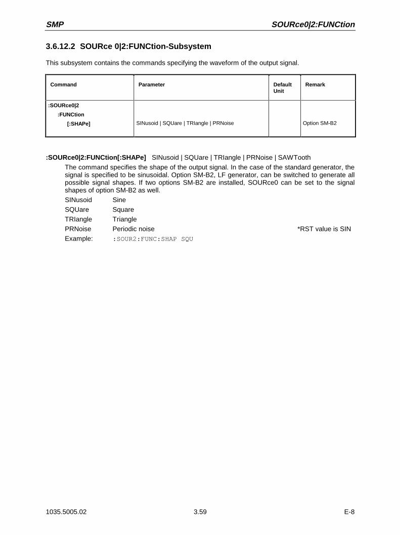
SMP SOURce0|2:FUNCtion
1035.5005.02 3.59 E-8
3.6.12.2 SOURce 0|2:FUNCtion-Subsystem
This subsystem contains the commands specifying the waveform of the output signal.
Command Parameter DefaultUnit
Remark
:SOURce0|2
:FUNCtion
[:SHAPe] SINusoid | SQUare | TRIangle | PRNoise Option SM-B2
:SOURce0|2:FUNCtion[:SHAPe] SINusoid | SQUare | TRIangle | PRNoise | SAWTooth
The command specifies the shape of the output signal. In the case of the standard generator, thesignal is specified to be sinusoidal. Option SM-B2, LF generator, can be switched to generate allpossible signal shapes. If two options SM-B2 are installed, SOURce0 can be set to the signalshapes of option SM-B2 as well.
SINusoid Sine
SQUare Square
TRIangle Triangle
PRNoise Periodic noise *RST value is SIN
Example: :SOUR2:FUNC:SHAP SQU
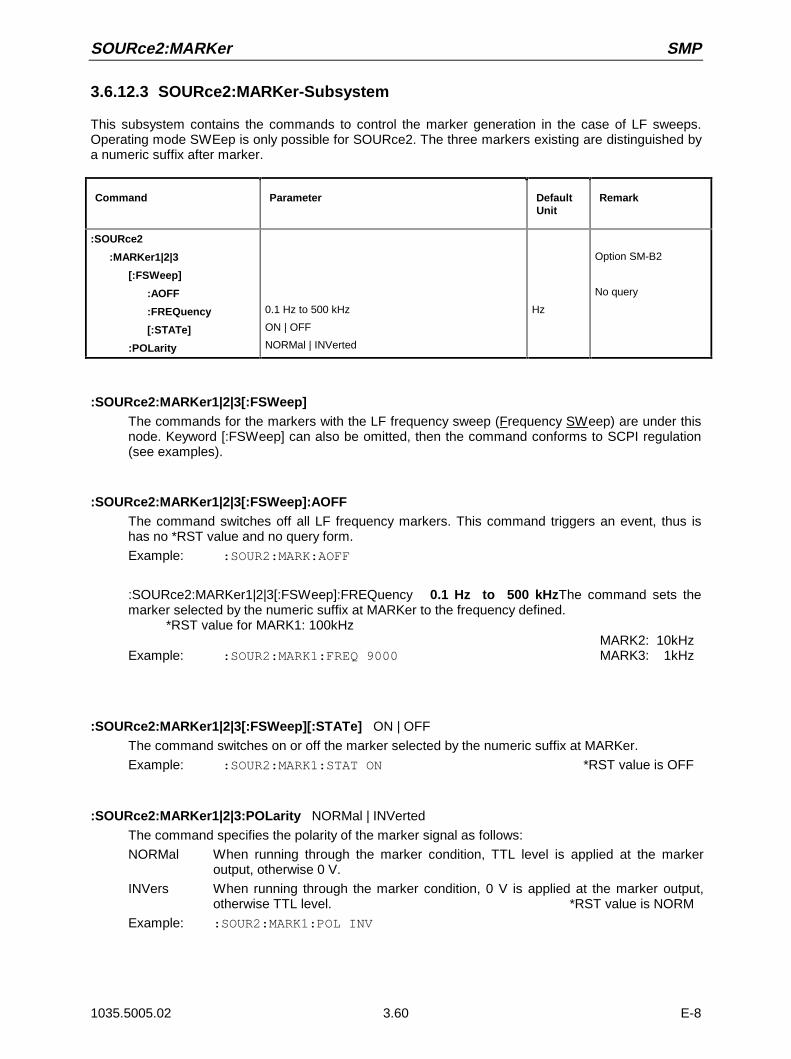
SOURce2:MARKer SMP
1035.5005.02 3.60 E-8
3.6.12.3 SOURce2:MARKer-Subsystem
This subsystem contains the commands to control the marker generation in the case of LF sweeps.Operating mode SWEep is only possible for SOURce2. The three markers existing are distinguished bya numeric suffix after marker.
Command Parameter DefaultUnit
Remark
:SOURce2
:MARKer1|2|3
[:FSWeep]
:AOFF
:FREQuency
[:STATe]
:POLarity
0.1 Hz to 500 kHz
ON | OFF
NORMal | INVerted
Hz
Option SM-B2
No query
:SOURce2:MARKer1|2|3[:FSWeep]The commands for the markers with the LF frequency sweep (Frequency SWeep) are under thisnode. Keyword [:FSWeep] can also be omitted, then the command conforms to SCPI regulation(see examples).
:SOURce2:MARKer1|2|3[:FSWeep]:AOFFThe command switches off all LF frequency markers. This command triggers an event, thus ishas no *RST value and no query form.
Example: :SOUR2:MARK:AOFF
:SOURce2:MARKer1|2|3[:FSWeep]:FREQuency 0.1 Hz to 500 kHzThe command sets themarker selected by the numeric suffix at MARKer to the frequency defined.
*RST value for MARK1: 100kHzMARK2: 10kHz
Example: :SOUR2:MARK1:FREQ 9000 MARK3: 1kHz
:SOURce2:MARKer1|2|3[:FSWeep][:STATe] ON | OFF
The command switches on or off the marker selected by the numeric suffix at MARKer.
Example: :SOUR2:MARK1:STAT ON *RST value is OFF
:SOURce2:MARKer1|2|3:POLarity NORMal | INVerted
The command specifies the polarity of the marker signal as follows:
NORMal When running through the marker condition, TTL level is applied at the markeroutput, otherwise 0 V.
INVers When running through the marker condition, 0 V is applied at the marker output,otherwise TTL level. *RST value is NORM
Example: :SOUR2:MARK1:POL INV

SMP SOURce2:SWEep
1035.5005.02 3.61 E-8
3.6.12.4 SOURce2:SWEep-Subsystem
This subsystem contains the commands to control the LF sweep of SOURce2. Sweeps are triggered onprinciple.
Command Parameter DefaultUnit
Remark
:SOURce2
:SWEep
:BTIMe
[:FREQuency]
:DWELl
:MODE
:POINts
:SPACing
:STEP
[:LINear]
:LOGarithmic
NORMal | LONG
1 ms to 5 s
AUTO | MANual | STEP
Number
LINear | LOGarithmic
0 to 500 kHz
0.01 PCT to 50 PCT
s
Hz
PCT
Option SM-B2
:SOURce2:SWEep:BTIMe NORMal | LONG
The command sets the blank time (Blank TIMe) of the sweep. The setting is valid for all sweeps,i.e., also for RF sweeps
NORMal Blank time as short as possible.
LONG Blank time long enough to permit an X/Y recorder to return to 0.
Example: :SOUR2:SWE:BTIM LONG *RST value is NORM
:SOURce2:SWEep[:FREQuency]The commands to set the frequency sweeps are under this node. Keyword [:FREQuency] can beomitted. Then the commands are SCPI-compatible unless stated otherwise (see examples).
:SOURce2:SWEep[:FREQuency]:DWELl 1 ms to 5 s
The command sets the time per frequency step (dwell).
Example: :SOUR2:SWE:DWEL 20ms *RST value is 15 ms
:SOURce2:SWEep[:FREQuency]:MODE AUTO | MANual | STEP
The command specifies the run of the sweep.
AUTOEach trigger triggers exactly one entire sweep cycle.
STEP Each trigger triggers only one sweep step (single-step mode). The frequencyincreases by the value defined under :SOURce2:SWEep
Example: :SOUR2:SWE:MODE AUTO *RST value is AUTO

SOURce2:SWEep SMP
1035.5005.02 3.62 E-8
:SOURce2:SWEep[:FREQuency]:POINts Number
The command determines the number of steps in a sweep. Instead of this command, commands:SOURce2:FREQuency:STEP:LINear and :SOURce2 :FREQuency:STEP:LOGarithmicshould be used, as :SOURce2:SWEep:FREQuency: POINts has been adapted to theinstrument characteristics in comparison to the SCPI command. The value of POINts depends onSPAN and STEP according to the following formulas.
The following is true of linear sweeps : POINts = SPAN / STEP:LIN + 1
The following is true of logarithmic sweeps and STARt < STOP:
POINts = ((log STOP log STARt) / log STEP:LOG) + 1
Two independent POINts values are used for SPACing LOG and SPACing LIN. That is to say,before POINts is changed, SPACing must be set correctly. A change of POINts causes anadaption of STEP, but not of STARt, STOP and SPAN.
Example: :SOUR2:SWE:POIN 50
:SOURce2:SWEep[:FREQuency]:SPACing LINear | LOGarithmic
The command selects whether the steps have linear or logarithmic spacings.
Example: :SOUR2:SWE:SPAC LOG *RST value is LINear
:SOURce2:SWEep[:FREQuency]:STEPThe commands to set the step width with linear and logarithmic sweeps are under this node. Thesettings of STEP:LIN and STEP:LOG are independent of each other.
:SOURce2:SWEep[:FREQuency]:STEP[:LINear] 0 to 500 kHz
The command sets the step width with the linear sweep. If STEP:LINear is changed, the value ofPOINts valid for SPACing:LINear also changes according to the formula defined under POINts. Achange of SPAN does not cause a change of STEP:LINear. Keyword [:LINear] can be omitted,then the command conforms to SCPI regulation (see example)
Example: :SOUR2:SWE:STEP 10kHz *RST value is 1 kHz
:SOURce2:SWEep[:FREQuency]:STEP:LOGarithmic 0.01 to 50PCT
The command defines the step width factor for logarithmic sweeps. The next frequency value of asweep is calculated according to (if STARt < STOP) :
new frequency = prior frequency + STEP:LOG x prior frequency
Thus STEP:LOG defines the fraction of the prior frequency by which this is increased for the nextsweep step. Usually STEP:LOG is defined in percent, with the suffix PCT having to be usedexplicitly. If STEP:LOG is changed, the value of POINts valid for SPACing:LOGarithmic alsochanges according to the formula stated unde
Example: :SOUR2:SWE:STEP:LOG 5PCT *RST value is 1 PCT
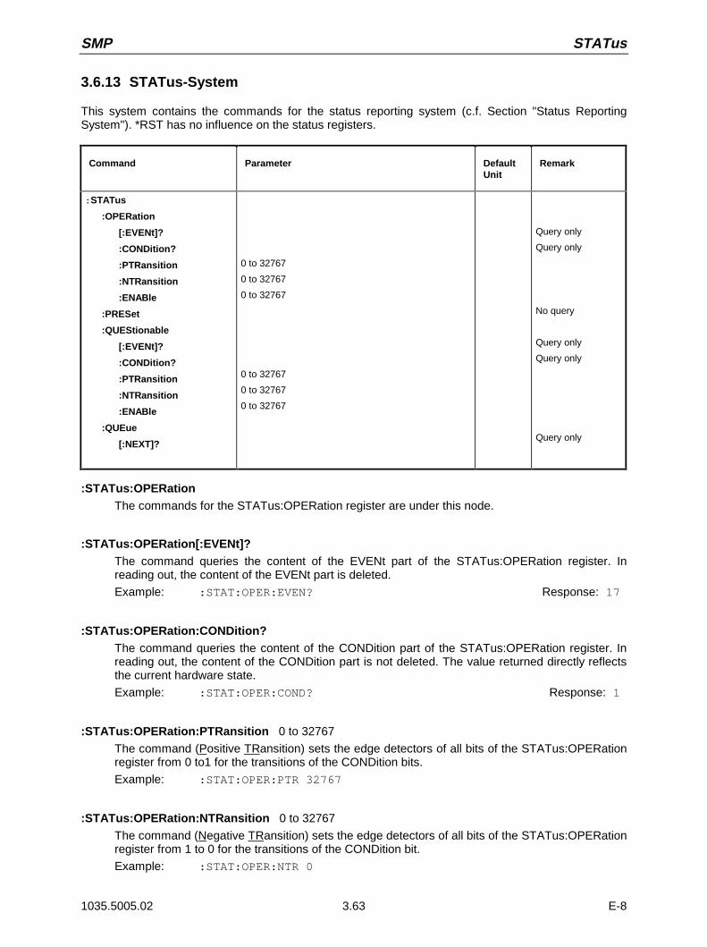
SMP STATus
1035.5005.02 3.63 E-8
3.6.13 STATus-System
This system contains the commands for the status reporting system (c.f. Section "Status ReportingSystem"). *RST has no influence on the status registers.
Command Parameter DefaultUnit
Remark
:STATus
:OPERation
[:EVENt]?
:CONDition?
:PTRansition
:NTRansition
:ENABle
:PRESet
:QUEStionable
[:EVENt]?
:CONDition?
:PTRansition
:NTRansition
:ENABle
:QUEue
[:NEXT]?
0 to 32767
0 to 32767
0 to 32767
0 to 32767
0 to 32767
0 to 32767
Query only
Query only
No query
Query only
Query only
Query only
:STATus:OPERationThe commands for the STATus:OPERation register are under this node.
:STATus:OPERation[:EVENt]?The command queries the content of the EVENt part of the STATus:OPERation register. Inreading out, the content of the EVENt part is deleted.
Example: :STAT:OPER:EVEN? Response: 17
:STATus:OPERation:CONDition?The command queries the content of the CONDition part of the STATus:OPERation register. Inreading out, the content of the CONDition part is not deleted. The value returned directly reflectsthe current hardware state.
Example: :STAT:OPER:COND? Response: 1
:STATus:OPERation:PTRansition 0 to 32767
The command (Positive TRansition) sets the edge detectors of all bits of the STATus:OPERationregister from 0 to1 for the transitions of the CONDition bits.
Example: :STAT:OPER:PTR 32767
:STATus:OPERation:NTRansition 0 to 32767
The command (Negative TRansition) sets the edge detectors of all bits of the STATus:OPERationregister from 1 to 0 for the transitions of the CONDition bit.
Example: :STAT:OPER:NTR 0
STATus SMP
1035.5005.02 3.64 E-8
:STATus:OPERation:ENABle 0 to 32767
The command sets the bits of the ENABle register. This register selectively enables the individualevents of the appropriate status event register for the sum bit in the status byte.
Example: :STAT:OPER:ENAB 1
:STATus:PRESetThe command resets the edge detectors and ENABle parts of all registers to a defined value. AllPTRansition parts are set to FFFFh, i.e., all transitions from 0 to 1 are detected. All NTRansitionparts are set to 0, i.e., a transition from 1 to 0 in a CONDition bit is not detected. The ENABleparts of STATus:OPERation and STATus:QUEStionable are set to 0, i.e., all events in theseregisters are not passed on.
Example: :STAT:PRES
:STATus:QUEStionableThe commands for the STATus:QUEStionable register are under this node.
:STATus:QUEStionable[:EVENt]?The command queries the content of the EVENt part of the STATus:QUEStionable register. Inreading out, the content of the EVENt part is deleted.
Example: :STAT:QUES:EVEN? Response: 1
:STATus:QUEStionable:CONDition?The command queries the content of the CONDition part of the STATus:QUEStionable register.In reading out, the content of the CONDition part is not deleted.
Example: :STAT:QUES:COND? Response: 2
:STATus:QUEStionable:PTRansition 0 to 32767STATus:QUEStionable:PTRansitionß to
The command (Positive TRansition) sets the edge detectors of all bits of theSTATus:QUEStionable register from 0 to 1 for transitions of the CONDition bit.
Example: :STAT:QUES:PTR 32767
:STATus:QUEStionable:NTRansition 0 to 32767
The command (Negative TRansition) sets the edge detectors of all bits of theSTATus:QUEStionable register from 1 to 0 for transitions of the CONDition bit.
Example: :STAT:QUES:NTR 0
:STATus:QUEStionable:ENABle 0 to 32767
The command sets the bits of the ENABle part of the STATus:QUEStionable register. This partselectively enables the individual events of the appropriate EVENt part for the sum bit in thestatus byte
Example: :STAT:QUES:ENAB 1
:STATus:QUEue [:NEXT]?The command queries the entry that has been in the error queue for the longest time and thusdeletes it. Positive error numbers denote errors specific of the instrument, negative error numberserror messages specified by SCPI (see annex B). If the error queue is empty, 0, "No error", isreturned. The command is identical to SYSTem :ERRor?
Example: STATus:QUEue:NEXT? Response: -221, "Settings conflict"
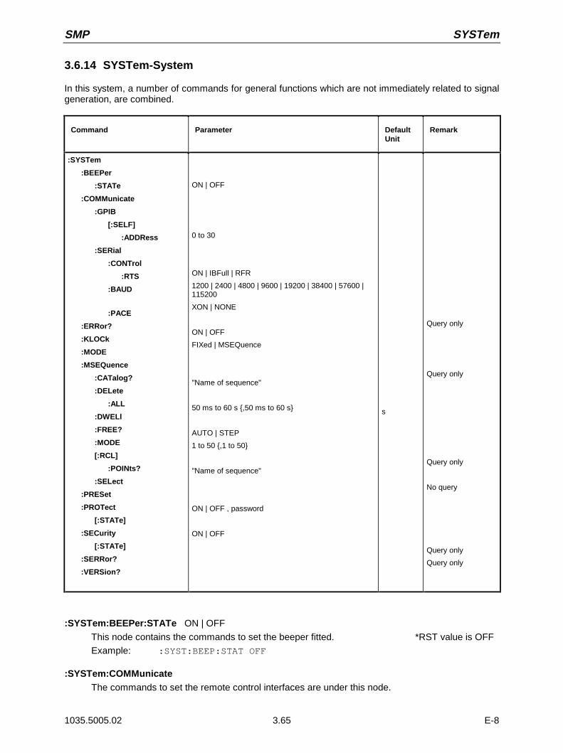
SMP SYSTem
1035.5005.02 3.65 E-8
3.6.14 SYSTem-System
In this system, a number of commands for general functions which are not immediately related to signalgeneration, are combined.
Command Parameter DefaultUnit
Remark
:SYSTem
:BEEPer
:STATe
:COMMunicate
:GPIB
[:SELF]
:ADDRess
:SERial
:CONTrol
:RTS
:BAUD
:PACE
:ERRor?
:KLOCk
:MODE
:MSEQuence
:CATalog?
:DELete
:ALL
:DWELl
:FREE?
:MODE
[:RCL]
:POINts?
:SELect
:PRESet
:PROTect
[:STATe]
:SECurity
[:STATe]
:SERRor?
:VERSion?
ON | OFF
0 to 30
ON | IBFull | RFR
1200 | 2400 | 4800 | 9600 | 19200 | 38400 | 57600 |115200
XON | NONE
ON | OFF
FIXed | MSEQuence
"Name of sequence"
50 ms to 60 s ,50 ms to 60 s
AUTO | STEP
1 to 50 ,1 to 50
"Name of sequence"
ON | OFF , password
ON | OFF
s
Query only
Query only
Query only
No query
Query only
Query only
:SYSTem:BEEPer:STATe ON | OFF
This node contains the commands to set the beeper fitted. *RST value is OFF
Example: :SYST:BEEP:STAT OFF
:SYSTem:COMMunicateThe commands to set the remote control interfaces are under this node.
SYSTem SMP
1035.5005.02 3.66 E-8
:SYSTem:COMMunicate:GPIBThe commands to control the IEC bus are under this node(GPIB = General Purpose Interface Bus)
:SYSTem:COMMunicate:GPIB[:SELF]:ADDRess 1 to 30
The command sets the IEC bus instrument address. *RST value is 28
Example: :SYST:COMM:GPIB:ADDR 1
:SYSTem:COMMunicate:SERialThe command to set the serial interface are under this node. The data format is fixedly set to 8data bits, no parity and 1 stop bit. These values cannot be changed. The device represents a DTE(Data Terminal Equipment) in relation to the serial interface. Therefore the the controller must beconnected via a 0-modem.
:SYSTem:COMMunicate:SERial:BAUD 1200| 2400| 4800| 9600| 19200| 38400| 57600| 115200
The commands sets the baud rate for both the transmit and the receive direction. *RST has noinflunence on this parameter.
Example: :SYST:COMM:SER:BAUD 1200 *RST value is 9600
:SYSTem:COMMunicate:SERial:CONTrol:RTS ON | IBFull | RFR
he commands sets the hardware handshake. *RST has no influence on this parameter.
ON Interface line RTS is always active.
IBFull | RFR Input Buffer Full | Ready For Receiving.Interface line RTS remains active as long as the instrument is ready to receive data
Example: :SYST:COMM:SER:CONT:RTS ON *RST value is RFR
:SYSTem:COMMunicate:SERial:PACE XON | NONE
The command sets the software handshake. *RST has no influnence on this parameter.
XON Software handshake using the ASCII codes 11h (XON) and 13h (XOFF).
Note: This mode is not recommended for binary data and for baud rates above9600 bauds.
NONE No software handshake.
Example: :SYST:COMM:SER:PACE NONE *RST value is NONE
:SYSTem:ERRor?The command queries the entry that has been in the error queue for the longest time. Positiveerror numbers denote errors specific of the instrument, negative error numbers denote errormessages specified by SCPI (see annex B). If the error queue is empty, 0, "No error", is returned.The command is identical to STATus:QUEue:NEXT?
Example: :SYST:ERR? Response: -221, "Settings conflict"

SMP SYSTem
1035.5005.02 3.67 E-8
:SYSTem:KLOCk ON | OFF
The command (Keyboard LOCk) disables the keyboard of the SMP including the [LOCAL] key orenables it again (OFF).
Caution: If :SYSTem:SECurity is ON, the keyboard cannot be enabled, i.e., :SYSTem:KLOCkOFF is not accepted. If the disabling of the command is released by switching overto :SYSTem:SECurity OFF, data will be lost.
Example: :SYST:KLOC ON *RST value is OFF
:SYSTem:MODE FIXed | MSEQence
The command sets the operating mode of the instrument.
FIXed The overall instrument state can only be switched over using *RCL.
MSEQuence The instrument successively sets the instrument states defined under:SYSTem:MSEQuence:RCL. *RST value is FIXed
Example: :SYST:MODE FIX
:SYSTem:MSEQuenceThis node follows the SOURce:LIST system. It can manage several memory sequences whicheach consist of a list of instrument state numbers and a time list. If :SYSTem:MODE is switchedto MSEQuence, the instrument states stated in the list selected are set successively for the timestated in the time list in each case.
:SYSTem:MSEQuence:CATalog?The command queries the memory sequences available. It returns a list, the entries areseparated by means of commas.
Example: :SYST:MSEQ:CAT? Response: "SEQ1", "DEMO", "SEQA"
:SYSTem:MSEQuence:DELete "Name of sequence"
The command deletes the memory sequence indicated.
Example: :SYST:MSEQ:DEL "SEQ1"
:SYSTem:MSEQuence:DELete:ALLThe command deletes all memory sequences. The memory-sequence mode must be switchedoff as a selected sequence cannot be deleted (SYSTem:MODE FIXed).
Example: :SYST:MSEQ:DEL:ALL
:SYSTem:MSEQuence:DWELl 50 ms to 60 s,50 ms to 60 s
For the memory sequence which has currently been selected, the command transmits a listindicating the time for which an instrument setting is "held" in each case before the instrumentproceeds to the next setting. If DWELl indicates only one parameter, every item of the instrumentstate list is set for the same, indicated time. Lists are not influenced by *RST.
Example: :SYST:MSEQ:DWEL 1s
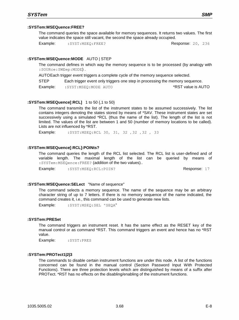
SYSTem SMP
1035.5005.02 3.68 E-8
:SYSTem:MSEQuence:FREE?The command queries the space available for memory sequences. It returns two values. The firstvalue indicates the space still vacant, the second the space already occupied.
Example: :SYST:MSEQ:FREE? Response: 20, 236
:SYSTem:MSEQuence:MODE AUTO | STEP
The command defines in which way the memory sequence is to be processed (by analogy with:SOURce:SWEep:MODE) .
AUTOEach trigger event triggers a complete cycle of the memory sequence selected.
STEP Each trigger event only triggers one step in processing the memory sequence.
Example: :SYST:MSEQ:MODE AUTO *RST value is AUTO
:SYSTem:MSEQuence[:RCL] 1 to 50 ,1 to 50
The command transmits the list of the instrument states to be assumed successively. The listcontains integers denoting the states stored by means of *SAV. These instrument states are setsuccessively using a simulated *RCL (thus the name of the list). The length of the list is notlimited. The values of the list are between 1 and 50 (number of memory locations to be called).Lists are not influenced by *RST.
Example: :SYST:MSEQ:RCL 30, 31, 32 ,32 ,32 , 33
:SYSTem:MSEQuence[:RCL]:POINts?The command queries the length of the RCL list selected. The RCL list is user-defined and ofvariable length. The maximal length of the list can be queried by means of:SYSTem:MSEQence:FREE? (addition of the two values)..
Example: :SYST:MSEQ:RCL:POIN? Response: 17
:SYSTem:MSEQuence:SELect "Name of sequence"
The command selects a memory sequence. The name of the sequence may be an arbitrarycharacter string of up to 7 letters. If there is no memory sequence of the name indicated, thecommand creates it, i.e., this command can be used to generate new lists.
Example: :SYST:MSEQ:SEL "SEQA"
:SYSTem:PRESetThe command triggers an instrument reset. It has the same effect as the RESET key of themanual control or as command *RST. This command triggers an event and hence has no *RSTvalue.
Example: :SYST:PRES
:SYSTem:PROTect1|2|3The commands to disable certain instrument functions are under this node. A list of the functionsconcerned can be found in the manual control (Section Password Input With ProtectedFunctions). There are three protection levels which are distinguished by means of a suffix afterPROTect. *RST has no effects on the disabling/enabling of the instrument functions.
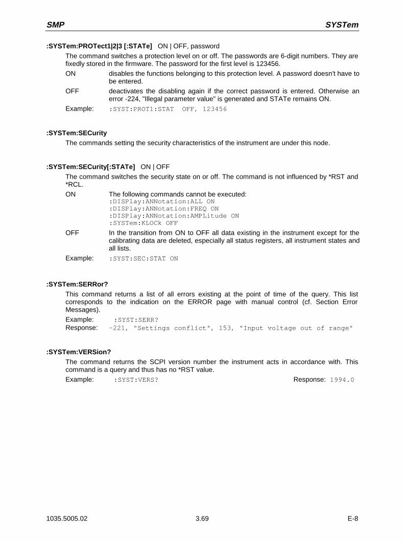
SMP SYSTem
1035.5005.02 3.69 E-8
:SYSTem:PROTect1|2|3 [:STATe] ON | OFF, password
The command switches a protection level on or off. The passwords are 6-digit numbers. They arefixedly stored in the firmware. The password for the first level is 123456.
ON disables the functions belonging to this protection level. A password doesn’t have tobe entered.
OFF deactivates the disabling again if the correct password is entered. Otherwise anerror -224, "Illegal parameter value" is generated and STATe remains ON.
Example: :SYST:PROT1:STAT OFF, 123456
:SYSTem:SECurityThe commands setting the security characteristics of the instrument are under this node.
:SYSTem:SECurity[:STATe] ON | OFF
The command switches the security state on or off. The command is not influenced by *RST and*RCL.
ON The following commands cannot be executed::DISPlay:ANNotation:ALL ON:DISPlay:ANNotation:FREQ ON:DISPlay:ANNotation:AMPLitude ON:SYSTem:KLOCk OFF
OFF In the transition from ON to OFF all data existing in the instrument except for thecalibrating data are deleted, especially all status registers, all instrument states andall lists.
Example: :SYST:SEC:STAT ON
:SYSTem:SERRor?This command returns a list of all errors existing at the point of time of the query. This listcorresponds to the indication on the ERROR page with manual control (cf. Section ErrorMessages).
Example: :SYST:SERR?Response: -221, "Settings conflict", 153, "Input voltage out of range"
:SYSTem:VERSion?The command returns the SCPI version number the instrument acts in accordance with. Thiscommand is a query and thus has no *RST value.
Example: :SYST:VERS? Response: 1994.0

TEST SMP
1035.5005.02 3.70 E-8
3.6.15 TEST-System
This system contains the commands to execute the selftest routines (RAM?, ROM? and BATTery?) aswell as to directly manipulate the hardware modules (:TEST:DIRect). The selftests return a "0" if the testhas been executed successfully, otherwise a value unequal to "0". All commands of this system do nothave an *RST value.
Caution: The commands under node :TEST:DIRect directly act on the respective hardware modulecircumventing any security mechanisms. They are provided for service purposes andshould not be used by the user. Improper use of the commands may damage the module.
Command Parameter DefaultUnit
Remark
:TEST
:DIRect
:ALCA
:AXIFC
:DSYN0MUX
:DSYN1MUX
:FMOD
:LFGENA
:LFGENB
:MWIFC
:PUM
:REFSS
:ROSC
:YPLL
:RAM?
:ROM?
:BATTery?
Subaddress, hex data string
Subaddress, hex data string
Subaddress, hex data string
Subaddress, hex data string
Subaddress, hex data string
Subaddress, hex data string
Subaddress, hex data string
Subaddress, hex data string
Subaddress, hex data string
Subaddress, hex data string
Subaddress, hex data string
Subaddress, hex data string
query only
query only
query only
:TEST:DIRectThis node contains the commands directly acting on the respective hardware modulecircumventing any security mechanisms. The commands under this node have no short form.
:TEST:DIRect:MWIFC Subaddress, hex data string
The command directly acts on module MWIFC. A subaddress (0 or 1) must be entered as aparameter. The data are entered as a <string> (i.e., an ASCII character string enclosed inquotation marks) representing hexadecimal numbers. Thus characters 0 to 9 A to F may occur inthe character string.
Example: :TEST:DIR:MWIFC 0, "2F004D"

SMP TEST
1035.5005.02 3.71 E-8
TEST:DIRect:ALCA Subaddress, hex data string
The command acts on module ALCA. (cf. :TEST:DIR:MWIFC)
:TEST:DIRect:AXIFC Subaddress, hex data string
The command acts on module AXIFC. (cf. :TEST:DIR:MWIFC)
:TEST:DIRect:DSYN0MUX Subaddress, hex data string
The command acts on module DSYN. (cf. :TEST:DIR:MWIFC)
:TEST:DIRect:DSYN1MUX Subaddress, hex data string
The command acts on module DSYN. (cf. :TEST:DIR:MWIFC)
:TEST:DIRect:FMOD Subaddress, hex data string
The command acts on module FMOD. (cf. :TEST:DIR:MWIFC)
:TEST:DIRect:LFGENA Subaddress, hex data string
The command acts on module LFGENA. (cf. :TEST:DIR:MWIFC)
:TEST:DIRect:LFGENB Subaddress, hex data string
The command acts on module LFGENB. (cf. :TEST:DIR:MWIFC)
:TEST:DIRect:PUM Subaddress, hex data string
The command acts on module PUM. (cf. :TEST:DIR:MWIFC)
:TEST:DIRect:REFSS Subaddress, hex data string
The command acts on module REFSS. (cf. :TEST:DIR:MWIFC)
:TEST:DIRect:ROSC Subaddress, hex data string
The command acts on module ROSC. (cf. :TEST:DIR:MWIFC)
:TEST:DIRect:YPLL Subaddress, hex data string
The command acts on module YPLL. (cf. :TEST:DIR:MWIFC)
:TEST:RAM?The command triggers a test of the RAM.
:TEST:ROM?The command triggers a test of the main memory (EEPROM).
:TEST:BATTery?The command triggers a test of the battery voltage.

TRIGger SMP
1035.5005.02 3.72 E-8
3.6.16 TRIGger-System
The TRIGger system contains the commands to select the trigger source and to configure the externaltrigger socket. The trigger sources for the individual signal sources (RF, LFGEN1, LFGEN2) aredistinguished by a numerical suffix appended to TRIGger. The suffix conforms to the numbering of theSOURce system:
TRIGger1 = RF generator
TRIGger2 = LFGEN2
The trigger system of the SMP consists of a simplified implementation of the SCPI trigger system.Compared to SCPI, the TRIGger system shows the following differences:
• No INITiate command, the instrument behaves as if INITiate:CONTinuous ON was set.
• There are several subsystems denoting the different parts of the instrument under TRIGger (SWEep,LIST, PULSe, MSEQuence, DM).
Further commands as to the trigger system of the SMP can be found in the ABORt system.
Command Parameter DefaultUnit
Remark
:TRIGger1|2
[:SWEep]
[:IMMediate]
:SOURce
:LIST
[:IMMediate]
:SOURce
:MSEQuence
[:IMMediate]
:SOURce
:PULSe
:SOURce
:SLOPe
:SLOPe
SINGle | EXTernal | AUTO
SINGle | EXTernal | AUTO
SINGle | EXTernal | AUTO
EXTernal | AUTO
POSitive | NEGative
POSitive | NEGative | EITHer
No query
No query
No query
:TRIGger1|2[:SWEep]All commands to trigger a sweep are under this node. The settings here act on level andfrequency sweeps for RF generator (TRIG1) and LF generator (TRIG2).
:TRIGger1|2[:SWEep][:IMMediate]The command immediately starts a sweep. Which sweep is executed depends on the respectiveMODE setting, e.g. :SOURce:FREQuency:MODE SWEep. The command corresponds tomanual-control command EXECUTE SINGLE SWEEP. This command triggers an event and thushas no *RST value.
Example: :TRIG:SWE:IMM
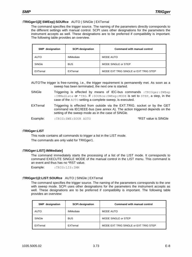
SMP TRIGger
1035.5005.02 3.73 E-8
:TRIGger1|2[:SWEep]:SOURce AUTO | SINGle | EXTernal
The command specifies the trigger source. The naming of the parameters directly corresponds tothe different settings with manual control. SCPI uses other designations for the parameters theinstrument accepts as well. These designations are to be preferred if compatibility is important.The following table provides an overview.
SMP designation SCPI designation Command with manual control
AUTO IMMediate MODE AUTO
SINGle BUS MODE SINGLE or STEP
EXTernal EXTernal MODE EXT TRIG SINGLE or EXT TRIG STEP
AUTOThe trigger is free-running, i.e., the trigger requirement is permanently met. As soon as asweep has been terminated, the next one is started.
SINGle Triggering is effected by means of IEC-bus commands :TRIGger:SWEep:IMMediate or *TRG. If :SOURce:SWEep:MODE is set to STEP, a step, in thecase of the AUTO setting a complete sweep, is executed.
EXTernal Triggering is effected from outside via the EXT.TRIG. socket or by the GETcommand via IEC/IEEE-bus (see annex A). The action triggered depends on thesetting of the sweep mode as in the case of SINGle.
Example: :TRIG:SWE:SOUR AUTO *RST value is SINGle
:TRIGger:LISTThis node contains all commands to trigger a list in the LIST mode.
The commands are only valid for TRIGger1.
:TRIGger:LIST[:IMMediate]The command immediately starts the processing of a list of the LIST mode. It corresponds tocommand EXECUTE SINGLE MODE of the manual control in the LIST menu. This command isan event and thus has no *RST value.
Example: :TRIG:LIS:IMM
:TRIGger1|2:LIST:SOURce AUTO | SINGle | EXTernal
The command specifies the trigger source. The naming of the parameters corresponds to the onewith sweep mode. SCPI uses other designations for the parameters the instrument accepts aswell. These designations are to be preferred if compatibility is important. The following tableprovides an overview:
SMP designation SCPI designation Command with manual control
AUTO IMMediate MODE AUTO
SINGle BUS MODE SINGLE or STEP
EXTernal EXTernal MODE EXT TRIG SINGLE or EXT TRIG STEP

TRIGger SMP
1035.5005.02 3.74 E-8
AUTOThe trigger is free-running, i.e., the trigger condition is permanently fulfilled. As soon as thelist selected has been finished in the LIST mode, it is started anew.
SINGle Triggering is executed by means of IEC-bus command :TRIGger:LIST :IMM. Thelist is executed once.
EXTernal Triggering is carried out from outside via the EXT.TRIG. socket or by the GETcommand via IEC/IEEE-bus (see annex A). The list is executed once
Example: :TRIG:LIS:SOUR AUTO *RST value is SINGle
:TRIGger:MSEQuenceThis node contains all commands to trigger a memory sequence. The commands are only validfor TRIGger1.
:TRIGger:MSEQuence[:IMMediate]The command immediately starts a memory sequence. It corresponds to the EXECUTE SINGLEMODE command of the manual control in the MEMORY SEQUENCE menu. This command is anevent and thus has no *RST value.
Example: :TRIG:MSEQ:IMM
:TRIGger:MSEQuence:SOURce AUTO | SINGle | EXTernal
The command specifies the trigger source (cf. :TRIGger:SWEep:SOURce)
Example: :TRIG:MSEQ:SOUR AUTO *RST value is SINGle
:TRIGger:PULSeThis node contains all commands to trigger the pulse generator (option SMP-B14). Thecommands are only valid for TRIGger1.
:TRIGger:PULSe:SOURce EXTernal | AUTO
The command specifies the trigger source.
EXTernal Triggering is effected from outside via the PULSE socket.
AUTOTrigger is free-running (see above) *RST value is AUTO
Example: :TRIG:PULS:SOUR AUTO
:TRIGger:PULSe:SLOPe POSitive | NEGative
The command defines whether the action triggered is triggered at the positive or the negativeedge of the trigger signal. *RST value is POSitiv
Example: :TRIG:PULS:SLOP NEG
:TRIGger:SLOPe POSitive | NEGative | EITHer
The command defines whether the external trigger input responds to the positive, the negative orto both edges of the trigger signal. The command acts on TRIGger:SWEep, TRIGger:LIST andTRIGger:MSEQuence. The pulse generator has an own trigger input and thus also an ownSLOPe command. *RST value is POSitiv
Example: :TRIG:SLOP NEG
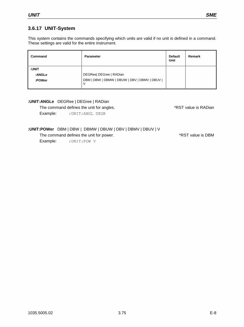
UNIT SME
1035.5005.02 3.75 E-8
3.6.17 UNIT-System
This system contains the commands specifying which units are valid if no unit is defined in a command.These settings are valid for the entire instrument.
Command Parameter DefaultUnit
Remark
:UNIT
:ANGLe
:POWer
DEGRee| DEGree | RADian
DBM | DBW | DBMW | DBUW | DBV | DBMV | DBUV |V
:UNIT:ANGLe DEGRee | DEGree | RADian
The command defines the unit for angles. *RST value is RADian
Example: :UNIT:ANGL DEGR
:UNIT:POWer DBM | DBW | DBMW | DBUW | DBV | DBMV | DBUV | V
The command defines the unit for power. *RST value is DBM
Example: :UNIT:POW V
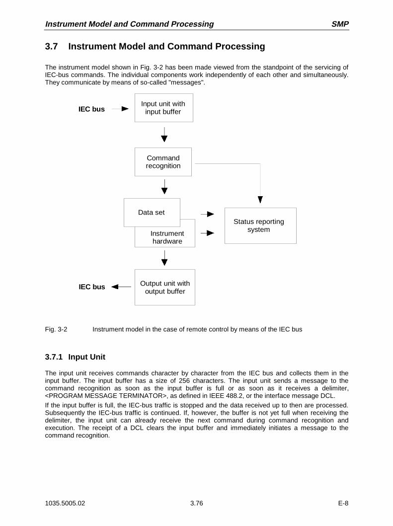
Instrument Model and Command Processing SMP
1035.5005.02 3.76 E-8
3.7 Instrument Model and Command Processing
The instrument model shown in Fig. 3-2 has been made viewed from the standpoint of the servicing ofIEC-bus commands. The individual components work independently of each other and simultaneously.They communicate by means of so-called "messages".
IEC busInput unit with
input buffer
Commandrecognition
Data set
Instrument hardware
IEC bus Output unit withoutput buffer
Status reportingsystem
Fig. 3-2 Instrument model in the case of remote control by means of the IEC bus
3.7.1 Input Unit
The input unit receives commands character by character from the IEC bus and collects them in theinput buffer. The input buffer has a size of 256 characters. The input unit sends a message to thecommand recognition as soon as the input buffer is full or as soon as it receives a delimiter,<PROGRAM MESSAGE TERMINATOR>, as defined in IEEE 488.2, or the interface message DCL.
If the input buffer is full, the IEC-bus traffic is stopped and the data received up to then are processed.Subsequently the IEC-bus traffic is continued. If, however, the buffer is not yet full when receiving thedelimiter, the input unit can already receive the next command during command recognition andexecution. The receipt of a DCL clears the input buffer and immediately initiates a message to thecommand recognition.
SMP Instrument Model and Command Processing
1035.5005.02 3.77 E-8
3.7.2 Command Recognition
The command recognition analyses the data received from the input unit. It proceeds in the order inwhich it receives the data. Only a DCL is serviced with priority, a GET (Group Execute Trigger), e.g., isonly executed after the commands received before as well. Each recognized command is immediatelytransferred to the data set but without being executed there at once.Syntactical errors in the command are recognized here and supplied to the status reporting system. Therest of a command line after a syntax error is analyzed further if possible and serviced.If the command recognition recognizes a delimiter or a DCL, it requests the data set to set thecommands in the instrument hardware as well now. Subsequently it is immediately prepared to processcommands again. This means for the command servicing that further commands can already beserviced while the hardware is still being set ("overlapping execution").
3.7.3 Data Set and Instrument Hardware
Here the expression "instrument hardware" denotes the part of the instrument fulfilling the actualinstrument function - signal generation, measurement etc. The controller is not included.
The data set is a detailed reproduction of the instrument hardware in the software.
IEC-bus setting commands lead to an alteration in the data set. The data set management enters thenew values (e.g. frequency) into the data set, however, only passes them on to the hardware whenrequested by the command recognition. As this is always only effected at the end of a command line,the order of the setting commands in the command line is not relevant.
The data are only checked for their compatibility among each other and with the instrument hardwareimmediately before they are transmitted to the instrument hardware. If the detection is made that anexecution is not possible, an "execution error" is signaled to the status reporting system. All alterationsof the data set are canceled, the instrument hardware is not reset. Due to the delayed checking andhardware setting, however, it is permissible to set impermissible instrument states within one commandline for a short period of time without this leading to an error message (example: simultaneous activationof FM and PM). At the end of the command line, however, a permissible instrument state must havebeen reached again.
Before passing on the data to the hardware, the settling bit in the STATus:OPERation register is set.The hardware executes the settings and resets the bit again as soon as the new state has settled. Thisfact can be used to synchronize command servicing.
IEC-bus queries induce the data set management to send the desired data to the output unit.
3.7.4 Status Reporting System
The status reporting system collects information on the instrument state and makes it available to theoutput unit on request. The exact structure and function are described in Section "Starting ReportingSystem".
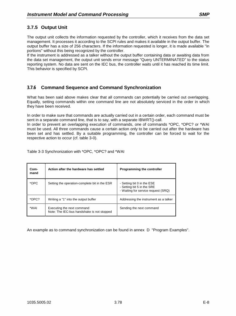
Instrument Model and Command Processing SMP
1035.5005.02 3.78 E-8
3.7.5 Output Unit
The output unit collects the information requested by the controller, which it receives from the data setmanagement. It processes it according to the SCPI rules and makes it available in the output buffer. Theoutput buffer has a size of 256 characters. If the information requested is longer, it is made available "inportions" without this being recognized by the controller.If the instrument is addressed as a talker without the output buffer containing data or awaiting data fromthe data set management, the output unit sends error message "Query UNTERMINATED" to the statusreporting system. No data are sent on the IEC bus, the controller waits until it has reached its time limit.This behavior is specified by SCPI.
3.7.6 Command Sequence and Command Synchronization
What has been said above makes clear that all commands can potentially be carried out overlapping.Equally, setting commands within one command line are not absolutely serviced in the order in whichthey have been received.
In order to make sure that commands are actually carried out in a certain order, each command must besent in a separate command line, that is to say, with a separate IBWRT()-call.In order to prevent an overlapping execution of commands, one of commands *OPC, *OPC? or *WAImust be used. All three commands cause a certain action only to be carried out after the hardware hasbeen set and has settled. By a suitable programming, the controller can be forced to wait for therespective action to occur (cf. table 3-0).
Table 3-3 Synchronization with *OPC, *OPC? and *WAI
Com-mand
Action after the hardware has settled Programming the controller
*OPC Setting the operation-complete bit in the ESR - Setting bit 0 in the ESE- Setting bit 5 in the SRE- Waiting for service request (SRQ)
*OPC? Writing a "1" into the output buffer Addressing the instrument as a talker
*WAI Executing the next commandNote: The IEC-bus handshake is not stopped
Sending the next command
An example as to command synchronization can be found in annex D "Program Examples".
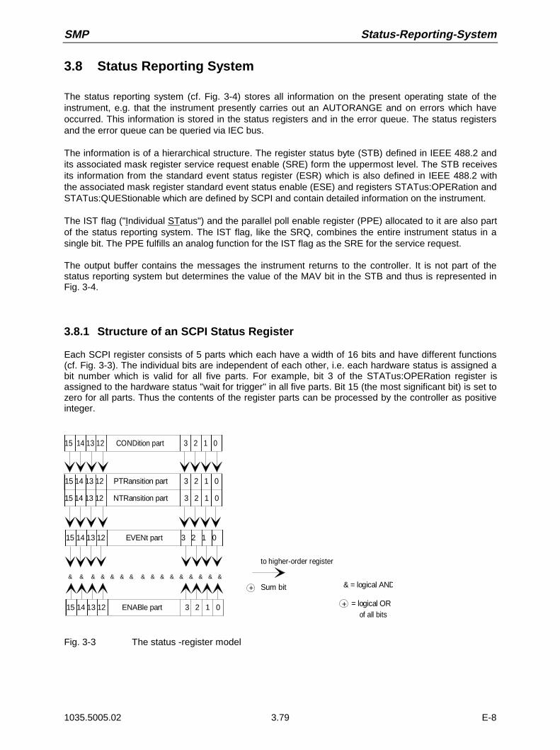
SMP Status-Reporting-System
1035.5005.02 3.79 E-8
3.8 Status Reporting System
The status reporting system (cf. Fig. 3-4) stores all information on the present operating state of theinstrument, e.g. that the instrument presently carries out an AUTORANGE and on errors which haveoccurred. This information is stored in the status registers and in the error queue. The status registersand the error queue can be queried via IEC bus.
The information is of a hierarchical structure. The register status byte (STB) defined in IEEE 488.2 andits associated mask register service request enable (SRE) form the uppermost level. The STB receivesits information from the standard event status register (ESR) which is also defined in IEEE 488.2 withthe associated mask register standard event status enable (ESE) and registers STATus:OPERation andSTATus:QUEStionable which are defined by SCPI and contain detailed information on the instrument.
The IST flag ("Individual STatus") and the parallel poll enable register (PPE) allocated to it are also partof the status reporting system. The IST flag, like the SRQ, combines the entire instrument status in asingle bit. The PPE fulfills an analog function for the IST flag as the SRE for the service request.
The output buffer contains the messages the instrument returns to the controller. It is not part of thestatus reporting system but determines the value of the MAV bit in the STB and thus is represented inFig. 3-4.
3.8.1 Structure of an SCPI Status Register
Each SCPI register consists of 5 parts which each have a width of 16 bits and have different functions(cf. Fig. 3-3). The individual bits are independent of each other, i.e. each hardware status is assigned abit number which is valid for all five parts. For example, bit 3 of the STATus:OPERation register isassigned to the hardware status "wait for trigger" in all five parts. Bit 15 (the most significant bit) is set tozero for all parts. Thus the contents of the register parts can be processed by the controller as positiveinteger.
15 14 13 12 PTRansition part 3 2 1 0
15 14 13 12 EVENt part 3 2 1 0
15 14 13 12 ENABle part 3 2 1 0
& & & & & & & & & & & & & & & &
to higher-order register
Sum bit & = logical AND
= logical ORof all bits
+
+
15 14 13 12 NTRansition part 3 2 1 0
15 14 13 12 CONDition part 3 2 1 0
Fig. 3-3 The status -register model

Status-Reporting-System SMP
1035.5005.02 3.80 E-8
CONDition part The CONDition part is directly written into by the hardware or the sum bit ofthe next lower register. Its contents reflects the current instrument status. Thisregister part can only be read, but not written into or cleared. Its contents is notaffected by reading.
PTRansition part The Positive-TRansition part acts as an edge detector. When a bit of theCONDition part is changed from 0 to 1, the associated PTR bit decideswhether the EVENt bit is set to 1.PTR bit =1: the EVENt bit is set.PTR bit =0: the EVENt bit is not set.This part can be written into and read at will. Its contents is not affected byreading.
NTRansition part The Negative-TRansition part also acts as an edge detector. When a bit of theCONDition part is changed from 1 to 0, the associated NTR bit decideswhether the EVENt bit is set to 1.NTR bit =1: the EVENt bit is set.NTR bit =0: the EVENt bit is not set.This part can be written into and read at will. Its contents is not affected byreading.With these two edge register parts the user can define which state transition ofthe condition part (none, 0 to 1, 1 to 0 or both) is stored in the EVENt part.
EVENt part The EVENt part indicates whether an event has occurred since the lastreading, it is the "memory" of the condition part. It only indicates eventspassed on by the edge filters. It is permanently updated by the instrument.This part can only be read by the user. During reading, its contents is set tozero. In linguistic usage this part is often equated with the entire register.
ENABle part The ENABle part determines whether the associated EVENt bit contributes tothe sum bit (cf. below). Each bit of the EVENt part is ANDed with theassociated ENABle bit (symbol ’&’). The results of all logical operations of thispart are passed on to the sum bit via an OR function (symbol ’+’).ENAB bit =0: the associated EVENt bit does not contribute to the sum bitENAB bit =1: if the associated EVENT bit is "1", the sum bit is set to "1" as
well.This part can be written into and read by the user at will. Its contents is notaffected by reading.
Sum bit As indicated above, the sum bit is obtained from the EVENt and ENABle partfor each register. The result is then entered into a bit of the CONDition part ofthe higher-order register.The instrument automatically generates the sum bit for each register. Thus anevent, e.g. a PLL that has not locked, can lead to a service request throughoutall levels of the hierarchy.
Note: The service request enable register SRE defined in IEEE 488.2 can be taken as ENABlepart of the STB if the STB is structured according to SCPI. By analogy, the ESE can betaken as the ENABle part of the ESR.
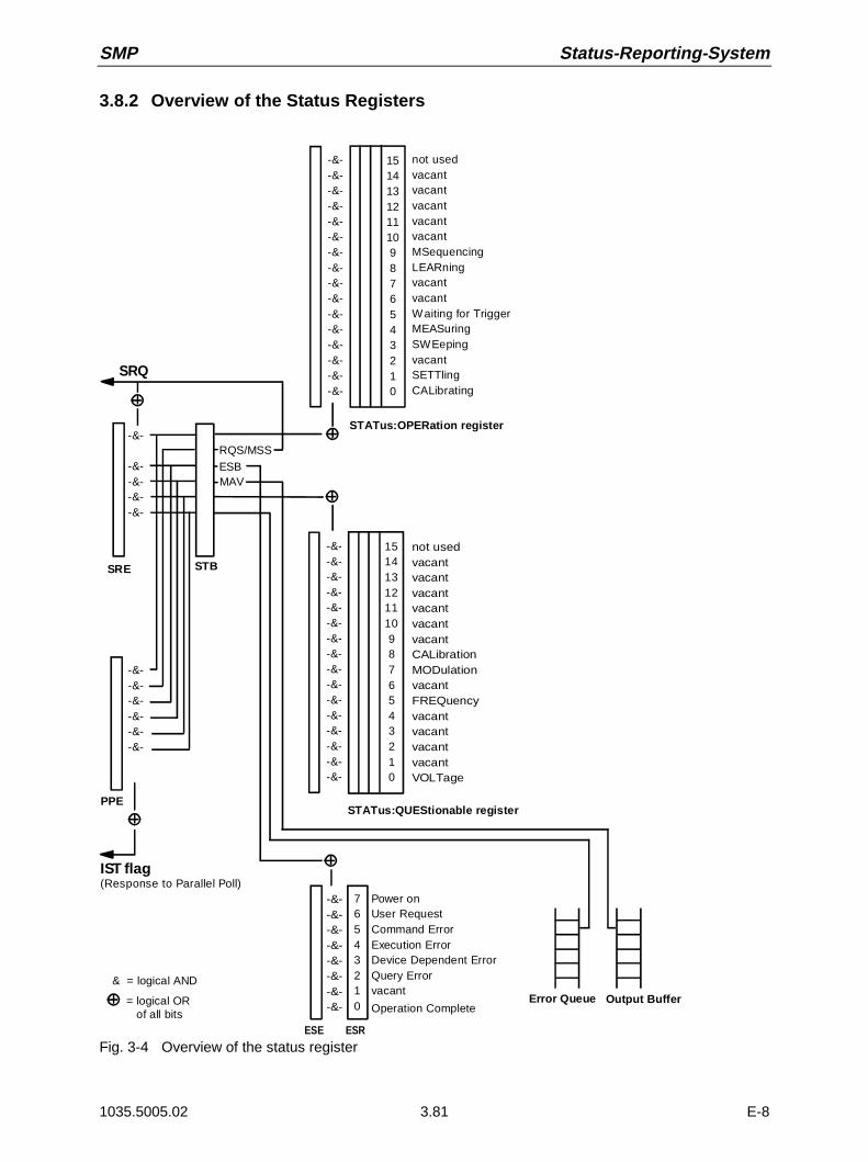
SMP Status-Reporting-System
1035.5005.02 3.81 E-8
3.8.2 Overview of the Status Registers
SRE STB
STATus:OPERation register
PPE
IST flag(Response to Parallel Poll)
& = logical AND
= logical OR of all bits
ESE ESR
Error Queue Output Buffer
SRQ
RQS/MSS
ESBMAV
Power onUser RequestCommand ErrorExecution ErrorDevice Dependent ErrorQuery Errorvacant
Operation Complete
1514131211109876543210
-&--&--&--&--&--&--&--&--&--&--&--&--&--&--&--&-
1514131211109876543210
-&--&--&--&--&--&--&--&--&--&--&--&--&--&--&--&-
-&--&--&--&--&--&-
-&-
-&--&--&--&-
-&--&--&--&--&--&--&--&-
76543210
STATus:QUEStionable register
not usedvacantvacantvacantvacantvacantMSequencingLEARningvacantvacantWaiting for TriggerMEASuringSWEepingvacantSETTlingCALibrating
not usedvacantvacantvacantvacantvacantvacantCALibrationMODulationvacantFREQuencyvacantvacantvacantvacantVOLTage
Fig. 3-4 Overview of the status register

Status-Reporting-System SMP
1035.5005.02 3.82 E-8
3.8.3 Description of the Status Registers
3.8.3.1 Status Byte (STB) and Service Request Enable Register (SRE)
The STB is already defined in IEEE 488.2. It provides a rough overview of the instrument status bycollecting the pieces of information of the lower registers. It can thus be compared with the CONDitionpart of an SCPI register and assumes the highest level within the SCPI hierarchy. A special feature isthat bit 6 acts as the sum bit of the remaining bits of the status byte.The STATUS BYTE is read out using the command "*STB?" or a serial poll.
The STB implies the SRE. It corresponds to the ENABle part of the SCPI registers as to its function.Each bit of the STB is assigned a bit in the SRE. Bit 6 of the SRE is ignored. If a bit is set in the SREand the associated bit in the STB changes from 0 to 1, a Service Request (SRQ) is generated on theIEC bus, which triggers an interrupt in the controller if this is appropriately configured and can be furtherprocessed there.The SRE can be set using command "*SRE" and read using "*SRE?".
Table 3-4 Meaning of the bits used in the status byte
Bit no. Meaning
2 Error Queue not empty
The bit is set when an entry is made in the error queue.If this bit is enabled by the SRE, each entry of the error queue generates a Service Request. Thus an error canbe recognized and specified in greater detail by polling the error queue. The poll provides an informative errormessage. This procedure is to be recommended since it considerably reduces the problems involved withIEC-bus control.
3 QUEStionable status sum bit
The bit is set if an EVENt bit is set in the QUEStionable status register and the associated ENABle bit is set to1.A set bit indicates a questionable instrument status, which can be specified in greater detail by polling theQUEStionable status register.
4 MAV-Bit (Message AVailable)
The bit is set if a message is available in the output buffer which can be read.This bit can be used to enable data to be automatically read from the instrument to the controller (cf. annex D,program examples).
5 ESB bit
Sum bit of the event status register. It is set if one of the bits in the event status register is set and enabled inthe event status enable register.Setting of this bit implies a serious error which can be specified in greater detail by polling the event statusregister.
6 MSS-Bit (Master Status Summary bit)
The bit is set if the instrument triggers a service request. This is the case if one of the other bits of this register isset together with its mask bit in the service request enable register SRE.
7 OPERation status register sum bit
The bit is set if an EVENt bit is set in the OPERation status register and the associated ENABle bit is set to 1.A set bit indicates that the instrument is just performing an action. The type of action can be determined bypolling the OPERation status register.
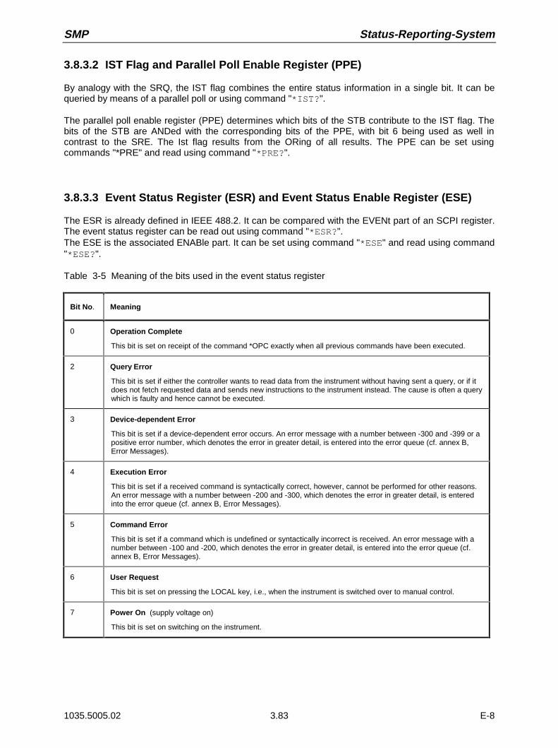
SMP Status-Reporting-System
1035.5005.02 3.83 E-8
3.8.3.2 IST Flag and Parallel Poll Enable Register (PPE)
By analogy with the SRQ, the IST flag combines the entire status information in a single bit. It can bequeried by means of a parallel poll or using command "*IST?".
The parallel poll enable register (PPE) determines which bits of the STB contribute to the IST flag. Thebits of the STB are ANDed with the corresponding bits of the PPE, with bit 6 being used as well incontrast to the SRE. The Ist flag results from the ORing of all results. The PPE can be set usingcommands "*PRE" and read using command "*PRE?".
3.8.3.3 Event Status Register (ESR) and Event Status Enable Register (ESE)
The ESR is already defined in IEEE 488.2. It can be compared with the EVENt part of an SCPI register.The event status register can be read out using command "*ESR?".The ESE is the associated ENABle part. It can be set using command "*ESE" and read using command"*ESE?".
Table 3-5 Meaning of the bits used in the event status register
Bit No. Meaning
0 Operation Complete
This bit is set on receipt of the command *OPC exactly when all previous commands have been executed.
2 Query Error
This bit is set if either the controller wants to read data from the instrument without having sent a query, or if itdoes not fetch requested data and sends new instructions to the instrument instead. The cause is often a querywhich is faulty and hence cannot be executed.
3 Device-dependent Error
This bit is set if a device-dependent error occurs. An error message with a number between -300 and -399 or apositive error number, which denotes the error in greater detail, is entered into the error queue (cf. annex B,Error Messages).
4 Execution Error
This bit is set if a received command is syntactically correct, however, cannot be performed for other reasons.An error message with a number between -200 and -300, which denotes the error in greater detail, is enteredinto the error queue (cf. annex B, Error Messages).
5 Command Error
This bit is set if a command which is undefined or syntactically incorrect is received. An error message with anumber between -100 and -200, which denotes the error in greater detail, is entered into the error queue (cf.annex B, Error Messages).
6 User Request
This bit is set on pressing the LOCAL key, i.e., when the instrument is switched over to manual control.
7 Power On (supply voltage on)
This bit is set on switching on the instrument.

Status-Reporting-System SMP
1035.5005.02 3.84 E-8
3.8.3.4 STATus:OPERation Register
In the CONDition part, this register contains information on which actions the instrument is beingexecuting or, in the EVENt part, information on which actions the instrument has executed since the lastreading. It can be read using commands "STATus:OPERation:CONDition?" or"STATus:OPERation [:EVENt]?"..
Table 3-6 Meaning of the bits used in the STATus:OPERation register
Bit-No. Meaning
0 CALibrating
This bit is set as long as the instrument is performing a calibration.
1 SETTling
This bit is set as long as the new status is settling after a setting command. It is only set if the settling time islonger than the command processing time.
3 SWEeping
This bit is set while the instrument is performing a sweep.
4 MEASuring
This bit is set while the instrument is performing a measurement.
5 WAIT for TRIGGER
This bit is set as long as the instrument is waiting for a trigger event.
8 LEARning
This bit is set while the instrument is "learning" a list.
9 MSEQuencing
This bit is set while the instrument is performing a memory sequence.

SMP Status-Reporting-System
1035.5005.02 3.85 E-8
3.8.3.5 STATus:QUEStionable Register
This register contains information on questionable instrument states. They can occur, e.g. if theinstrument is operated out of its specifications. It can be queried using commands "STATus:QUEStionable:CONDition?" or "STATus:QUEStionable[:EVENt]?".
Table 3-7 Meaning of the bits used in the STATus:QUEStionable register
Bit-No. Meaning
0 VOLTage
This bit is set if the voltage at an output connector is not correct,if the voltage is above or below the specified limit values,if the level limit has responded,if the overvoltage protection has responded.
5 FREQuency
The bit is set if a frequency at the RF output is not correct or if it is lower or higher than the specified values
7 MODulation
The bit is set if a modulation is not correct or is operated outside the specifications.
8 CALibration
The bit is set if a calibration is not performed properly.
Status-Reporting-System SMP
1035.5005.02 3.86 E-8
3.8.4 Application of the Status Reporting Systems
In order to be able to effectively use the status reporting system, the information contained there mustbe transmitted to the controller and further processed there. There are several methods which arerepresented in the following. Detailed program examples are to be found in annex D, ProgramExamples.
3.8.4.1 Service Request, Making Use of the Hierarchy Structure
Under certain circumstances, the instrument can send a service request (SRQ) to the controller. Usuallythis service request initiates an interrupt at the controller, to which the control program can react withcorresponding actions. As evident from Fig. 3.4, an SRQ is always initiated if one or several of bits 2, 3,4, 5 or 7 of the status byte are set and enabled in the SRE. Each of these bits combines the informationof a further register, the error queue or the output buffer. The corresponding setting of the ENABle partsof the status registers can achieve that arbitrary bits in an arbitrary status register initiate an SRQ. Inorder to make use of the possibilities of the service request, all bits should be set to "1" in enableregisters SRE and ESE.
Examples (cf. Fig. 3.4, Section "Program Examples", annex D as well):
Use of command "*OPC" to generate an SRQÀ Set bit 0 in the ESE (Operation Complete)À Set bit 5 in the SRE (ESB)
After its settings have been completed, the instrument generates an SRQ.
Indication of the end of a sweep by means of an SRQ with the controllerÀ Set bit 7 in the SRE (sum bit of the STATus:OPERation register)À Set bit 3 (sweeping )in the STATus:OPERation:ENABle.À Set bit 3 in the STATus:OPERation:NTRansition so as to make sure that the transition of
sweeping bit 3 from 1 to 0 (sweep end) is recorded in the EVENt part.
After a sweep has been completed, the instrument generates an SRQ.
The SRQ is the only possibility for the instrument to become active on its own. Each controller programshould set the instrument such that a service request is initiated in the case of malfunction. The programshould react appropriately to the service request. A detailed example for a service request routine is tobe found in annex D , Program Examples.
3.8.4.2 Serial Poll
In a serial poll, just as with command "*STB", the status byte of an instrument is queried. However, thequery is realized via interface messages and is thus clearly faster. The serial-poll method has alreadybeen defined in IEEE 488.1 and used to be the only standard possibility for different instruments to pollthe status byte. The method also works with instruments which do not adhere to SCPI or IEEE 488.2.
The quick-BASIC command for executing a serial poll is "IBRSP()". Serial poll is mainly used to obtaina fast overview of the state of several instruments connected to the IEC bus.
SMP Status-Reporting-System
1035.5005.02 3.87 E-8
3.8.4.3 Parallel Poll
In a parallel poll, up to eight instruments are simultaneously requested by the controller by means of asingle command to transmit 1 bit of information each on the data lines, i.e., to set the data line allocatedto each instrument to logically "0" or "1". By analogy to the SRE register which determines under whichconditions an SRQ is generated, there is a parallel poll enable register (PPE) which is ANDed with theSTB bit by bit as well considering bit 6. The results are ORed, the result is then sent (possibly inverted)as a response in the parallel poll of the controller. The result can also be queried without parallel poll bymeans of command "*IST".
The instrument first has to be set for the parallel poll using quick-BASIC command "IBPPC()". Thiscommand allocates a data line to the instrument and determines whether the response is to be inverted.The parallel poll itself is executed using "IBRPP()".
The parallel-poll method is mainly used in order to quickly find out after an SRQ which instrument hassent the service request if there are many instruments connected to the IEC bus. To this effect, SREand PPE must be set to the same value. A detailed example as to the parallel poll is to be found inannex D, Program Examples.
3.8.4.4 Query by Means of Commands
Each part of every status register can be read by means of queries. The individual commands areindicated in the detailed description of the registers in Section "Description of the Status Registers".What is returned is always a number which represents the bit pattern of the register queried. Evaluatingthis number is effected by the controller program.
Queries are usually used after an SRQ in order to obtain more detailed information on the cause of theSRQ.
3.8.4.5 Error Queue Query
Each error state in the instrument leads to an entry in the error queue. The entries of the error queue aredetailed plain-text error messages which can be looked at in the ERROR menu via manual control orqueried via the IEC bus using command "SYSTem:ERRor?". Each call of "SYSTem:ERRor?"provides one entry from the error queue. If no error messages are stored there any more, the instrumentresponds with 0, "No error"
The error queue should be queried after every SRQ in the controller program as the entries describe thecause of an error more precisely than the status registers. Especially in the test phase of a controllerprogram the error queue should be queried regularly since faulty commands from the controller to theinstrument are recorded there as well.

Status-Reporting-System SMP
1035.5005.02 3.88 E-8
3.8.5 Resetting Values of the Status Reporting Systems
Table 3-0 comprises the different commands and events causing the status reporting system to bereset. None of the commands, except for *RST and SYSTem:PRESet influences the functionalinstrument settings. In particular, DCL does not change the instrument settings.
Table 3-8 Resetting instrument functions
Event Switching onsupply voltage DCL,SDC
Power-On-Status-Clear
(Device Clear,Selected Device
Clear)
*RST orSYSTem:PRESet
STATus:PRESet *CLS
Effect 0 1
Clear STB,ESR yes yes
Clear SRE,ESE yes
Clear PPE yes
Clear EVENt parts of theregisters
yes yes
Clear ENABle parts of allOPERation-andQUESTionable registers,Fill ENABle parts of allother registers with "1".
yes yes
Fill PTRansition parts with„1"Clear NTRansition parts
yes yes
Clear error queue yes yes yes
Clear output buffer yes yes yes 1) 1) 1)
Clear commandprocessing and inputbuffer
yes yes yes
1) Every command being the first in a command line, i.e. immediately following a <PROGRAM MESSAGE TERMINATOR>clears the output buffer.
SMP Functional Test
1035.5005.02 E-84.1
4 Maintenance and Troubleshooting
The instrument does not need a periodic maintenance. What is necessary is essentially the cleaning ofthe instrument. However, it is recommended to check the rated data from time to time.
4.1 Maintenance
4.1.1 Cleaning the Outside
The outside of the instrument is suitably cleaned using a soft, line-free dustcloth.
Caution! Do not use solvents such as thinners, acetone and similar things in any case, becauseotherwise the front panel labeling or plastic parts will be damaged.
4.1.2 Storage
The storage temperature range of the instrument is -40 to +70 degrees Celsius. If the instrument is to bestored for a longer period of time, it must be protected against dust.
4.1.3 Exchange of the Lithium Battery
Caution!The battery used in the instrument is a power lithium cell. Short-circuit andcharging of the battery have to be avoided at all costs, as the battery mightohterwise explode. Do not open discharged batteries. They have to be disposedof as hazardous waste.
The instrument contains a lithium battery for non-volatile storage of data in the CMOS-RAM. The batteryis located on the computer PCB.The service life of the battery depends on the operation and the ambient temperature, it is 5 years onthe average.
The battery voltages are checked after power-up of the unit (TEST POINT 0007 = RAM cell). If thevoltage values are below 2.5 V storage of data can no longer be quaranteed and an error message isdisplayed.
In order to guarantee a perfect function, a flattened battery is to be replaced by a battery of the sametype:
- SAFT LS3 CNA, (R&S stock no. 565.1687) or- ELECTROCHE QTC85 1/2AA 3B960, (R&S stock no. 565.1687).
Notes: – When the RAM-battery is exchanged, the stored data (SAVE/RECALL, LIST, MEMSEQ, UCOR, IEC-bus address, calibration data) are lost. These data have to bereprogrammed after the exchange of the battery. Moreover, a calibration must beperformed for PULSE GEN, YFOM and ALC AMP.

Functional Test SMP
1035.5005.02 E-84.2
Opening theinstrument
ÀSwitch off instrument and disconnect power plag
ÀRemove all cable connections.
À Screw off front panel (4 Phillips screws at the corners) and tilt towards thefront.
The shielding cover (cf. Fig. 4-1) of the controller and the front panelmodules is now freely accessible.
À Detach cable connection to the IEC bus (Fig. 4-1, pos. 3) and to the RS-232interface (Fig. 4.1, pos. 4). The connection to the motherboard (Fig. 4-1,pos. 2) can remain plugged in.
À Screw off cover (6 screws (Fig. 4-1, pos. 1)) and lift off.
The computer PCB is now accessible from the top.
Exchanging thebattery
The position of the battery on the computer PCB is evident from Fig.4-2.
À Detach jumper X300 (cf. Fig. 4-2, pos. 2).
À Cut off cable tie.
À Unsolder battery.
À Detach cable at plug connector X312 (cf. Fig. 4-2, pos. 1). The remainingcable connections can remain plugged in.
À Remove 2 fastening screws (cf. Fig. 4-2, pos. 5) on the computer PCB.
À Lift computer PCB and thread new battery clamp.
À Screw on computer PCB (cf. Fig. 4-2, pos. 5), establish plug connectionX312 (cf. Fig. 4-2, pos. 1).
À Fix new battery in position using cable tie.
Caution! Observe the polarity when fixing and soldering the battery (cf. Fig.4-2 and marking on the PCB). A wrong polarity will lead to thedestruction of components.
À Shorten connection wires to the necessary length and solder battery.
À Plug jumper X300 (cf. Fig. 4-2, pos. 2).
Closing theinstrument
Closing the instrument is effected in the reverse order as opening it.
Caution! Ensure that the braided cord in the casing slots is fitted correctly.
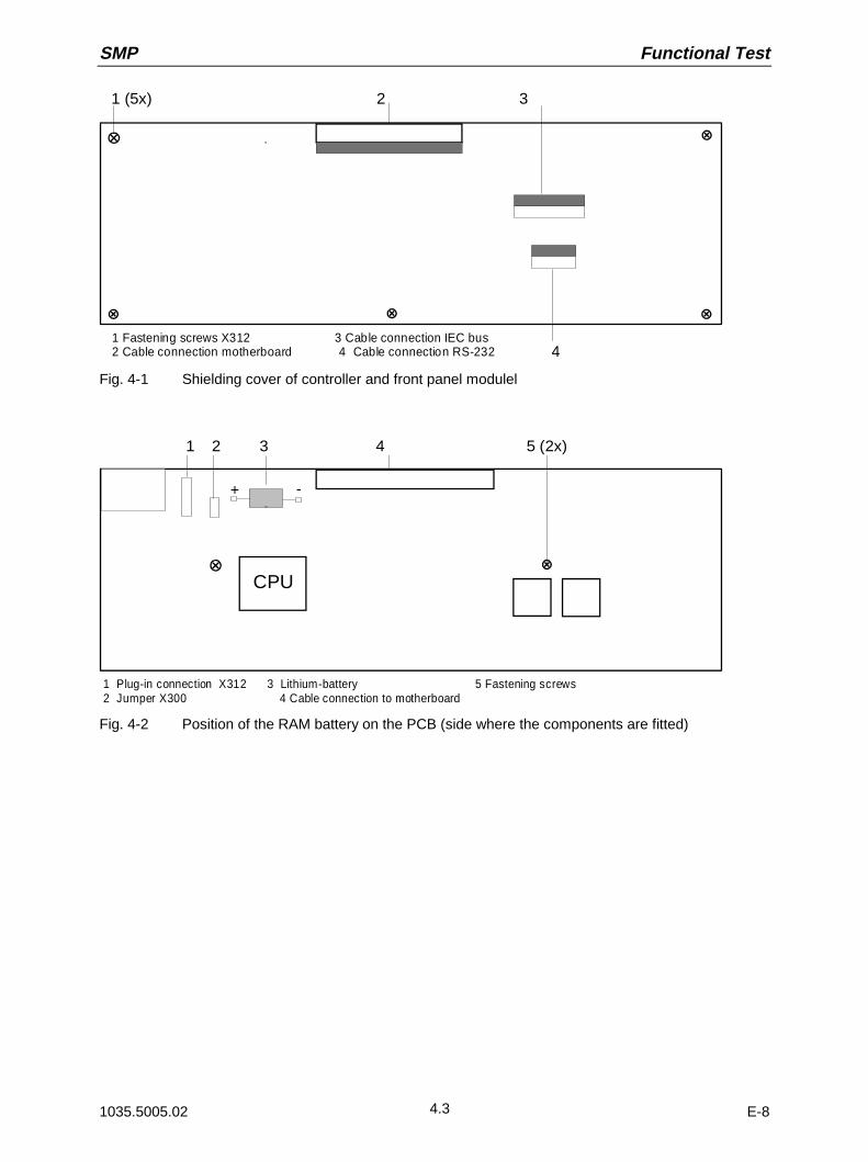
SMP Functional Test
1035.5005.02 E-84.3
1 Fastening screws X312 3 Cable connection IEC bus 2 Cable connection motherboard 4 Cable connection RS-232
1 (5x) 2 3
4
Fig. 4-1 Shielding cover of controller and front panel modulel
1 Plug-in connection X312 3 Lithium-battery 5 Fastening screws2 Jumper X300 4 Cable connection to motherboard
+ -
1 2 3 4 5 (2x)
CPU
Fig. 4-2 Position of the RAM battery on the PCB (side where the components are fitted)
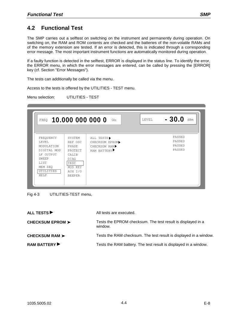
Functional Test SMP
1035.5005.02 E-84.4
4.2 Functional Test
The SMP carries out a selftest on switching on the instrument and permanently during operation. Onswitching on, the RAM and ROM contents are checked and the batteries of the non-volatile RAMs andof the memory extension are tested. If an error is detected, this is indicated through a correspondingerror message. The most important instrument functions are automatically monitored during operation.
If a faulty function is detected in the selftest, ERROR is displayed in the status line. To identify the error,the ERROR menu, in which the error messages are entered, can be called by pressing the [ERROR]key (cf. Section "Error Messages").
The tests can additionally be called via the menu.
Access to the tests is offered by the UTILITIES - TEST menu.
Menu selection: UTILITIES - TEST
FREQUENCYLEVELMODULATIONDIGITAL MODLF OUTPUTSWEEPLISTMEM SEQUTILITIESHELP
SYSTEMREF OSCPHASEPROTECTCALIBDIAGTESTMOD KEYAUX I/OBEEPER
ALL TESTSCHECKSUM EPROMCHECKSUM RAMRAM BATTERY
FREQ 10.000 000 000 0 GHz LEVEL - 30.0 dBm
PASSEDPASSEDPASSEDPASSED
Fig 4-3 UTILITIES-TEST menu,
ALL TESTS All tests are executed.
CHECKSUM EPROM Tests the EPROM checksum. The test result is displayed in awindow.
CHECKSUM RAM Tests the RAM checksum. The test result is displayed in a window.
RAM BATTERY Tests the RAM battery. The test result is displayed in a window.
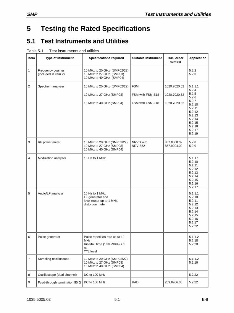
SMP Test Instruments and Utilities
1035.5005.02 E-85.1
5 Testing the Rated Specifications
5.1 Test Instruments and UtilitiesTable 5-1 Test instruments and utilities
Item Type of instrument Specifications required Suitable instrument R&S ordernumber
Application
1 Frequency counter(included in item 2)
10 MHz to 20 GHz (SMP02/22)10 MHz to 27 GHz (SMP03)10 MHz to 40 GHz (SMP04)
5.2.25.2.3
2 Spectrum analyzer 10 MHz to 20 GHz (SMP02/22)
10 MHz to 27 GHz (SMP03)
10 MHz to 40 GHz (SMP04)
FSM
FSM with FSM-Z18
FSM with FSM-Z18
1020.7020.52
1020.7020.52
1020.7020.52
5.1.1.15.2.45.2.55.2.65.2.75.2.105.2.115.2.125.2.135.2.145.2.155.2.165.2.175.2.19
3 RF power meter 10 MHz to 20 GHz (SMP02/22)10 MHz to 27 GHz (SMP03)10 MHz to 40 GHz (SMP04)
NRVD withNRV-Z52
857.8008.02857.9204.02
5.2.85.2.9
4 Modulation analyzer 10 Hz to 1 MHz 5.1.1.15.2.105.2.115.2.125.2.135.2.145.2.155.2.165.2.17
5 Audio/LF analyzer 10 Hz to 1 MHzLF generator andlevel meter up to 1 MHz,distortion meter
5.1.1.15.2.105.2.115.2.125.2.135.2.145.2.155.2.165.2.175.2.22
6 Pulse generator Pulse repetition rate up to 10MHzRise/fall time (10% /90%) < 1nsTTL level
5.1.1.25.2.185.2.20
7 Sampling oscilloscope 10 MHz to 20 GHz (SMP02/22)10 MHz to 27 GHz (SMP03)10 MHz to 40 GHz (SMP04)
5.1.1.25.2.18
8 Oscilloscope (dual channel) DC to 100 MHz 5.2.22
9 Feed-through termination 50 Ω DC to 100 MHz RAD 289.8966.00 5.2.22

Test Procedures SMP
1035.5005.02 E-85.2
5.1.1 Test Setups to Measure Modulation Characteristics
5.1.1.1 Standard Test System
Test equipment Spectrum analyzer (section 5.1, item 2)Modulation analyzer (section 5.1, item 4)Audio/LF analyzer (section 5.1, item 5)
Test setup
SMPSpectrumAnalyzer
ModulationAnalyzer
Audio/LFAnalyzer
RF
IF 21.4 MHz
LF
LF
EXT1/2 RF
5.1.1.2 Test System for Pulse Modulation
Test equipment Pulse generator (section 5.1, item 6)Sampling oscilloscope (section 5.1, item 7)
Test setup
SMP SamplingOscilloscope
PulseGenerator
RF
PULSE RF
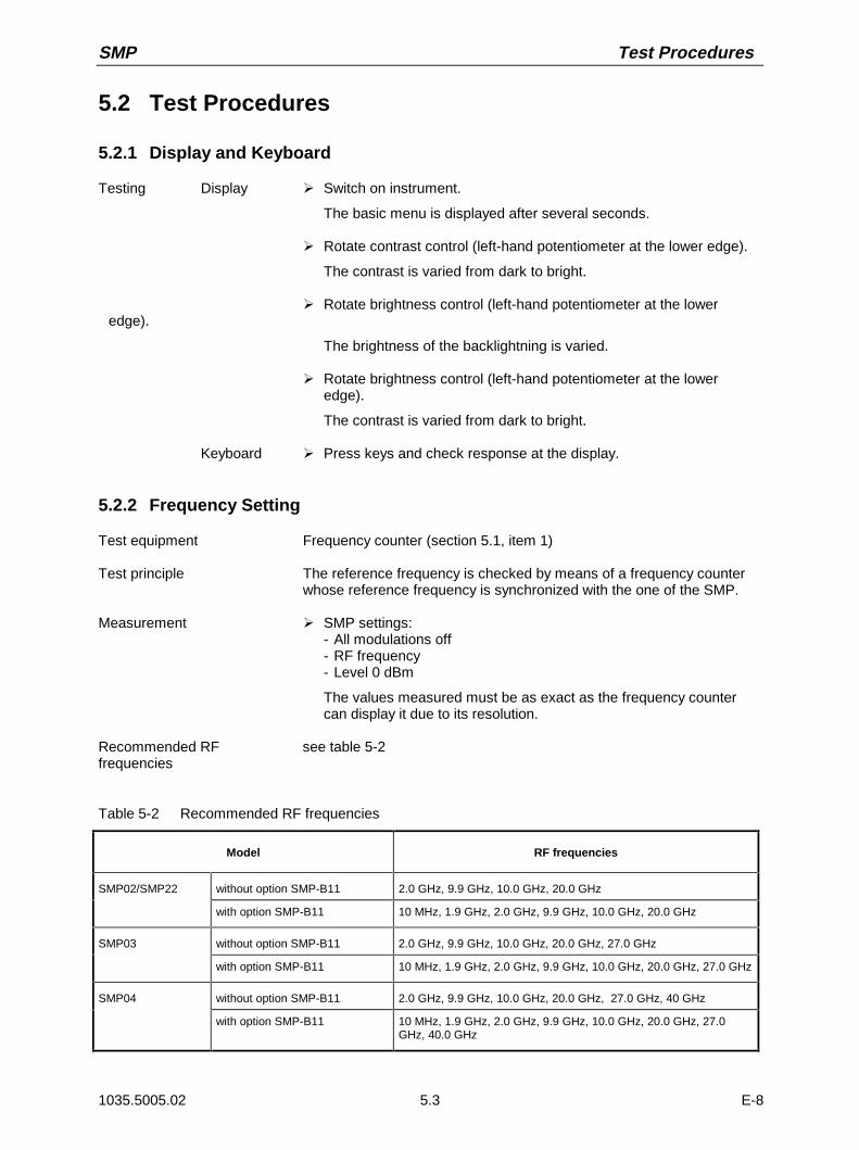
SMP Test Procedures
1035.5005.02 E-85.3
5.2 Test Procedures
5.2.1 Display and Keyboard
Testing Display À Switch on instrument.
The basic menu is displayed after several seconds.
À Rotate contrast control (left-hand potentiometer at the lower edge).
The contrast is varied from dark to bright.
À Rotate brightness control (left-hand potentiometer at the loweredge).
The brightness of the backlightning is varied.
À Rotate brightness control (left-hand potentiometer at the loweredge).
The contrast is varied from dark to bright.
Keyboard À Press keys and check response at the display.
5.2.2 Frequency Setting
Test equipment Frequency counter (section 5.1, item 1)
Test principle The reference frequency is checked by means of a frequency counterwhose reference frequency is synchronized with the one of the SMP.
Measurement À SMP settings:- All modulations off- RF frequency- Level 0 dBm
The values measured must be as exact as the frequency countercan display it due to its resolution.
Recommended RF see table 5-2frequencies
Table 5-2 Recommended RF frequencies
Model RF frequencies
SMP02/SMP22 without option SMP-B11 2.0 GHz, 9.9 GHz, 10.0 GHz, 20.0 GHz
with option SMP-B11 10 MHz, 1.9 GHz, 2.0 GHz, 9.9 GHz, 10.0 GHz, 20.0 GHz
SMP03 without option SMP-B11 2.0 GHz, 9.9 GHz, 10.0 GHz, 20.0 GHz, 27.0 GHz
with option SMP-B11 10 MHz, 1.9 GHz, 2.0 GHz, 9.9 GHz, 10.0 GHz, 20.0 GHz, 27.0 GHz
SMP04 without option SMP-B11 2.0 GHz, 9.9 GHz, 10.0 GHz, 20.0 GHz, 27.0 GHz, 40 GHz
with option SMP-B11 10 MHz, 1.9 GHz, 2.0 GHz, 9.9 GHz, 10.0 GHz, 20.0 GHz, 27.0GHz, 40.0 GHz
Test Procedures SMP
1035.5005.02 E-85.4
5.2.3 Reference Frequency
Caution: Allow the SMP to warm up for at least 2 hours before measurement.
Test equipment Frequency counter (section 5.1, item 1)
Test setup Connect a calibrated frequency counter to the REF output at the rearpanel of the SMP.
Measurement À Measure frequency.
Standard .................................< (1⋅10-6 + 2⋅10-6 per year of operating)With option SMP-B1 ... <(1⋅10-9 per day + 5⋅10-8 per year of operating)
5.2.4 Suppression of Harmonics
Test equipment Spectrum analyzer (section 5.1, item 2)
Test setup Connect the spectrum analyzer to the RF output of the SMP.
Measurement À Measure the third and the second harmonics( fundamental x 2 or x3) for each RF frequency. There is no need to measure harmonicsthat lie outside the nominal frequency range of the SMP model thatis tested.
À SMP settings:- All modulations off- Test frequency see table 5-3- Level see table 5-4
Supression of harmonics.................................................see table 5-4
À Measure harmonics when pulse modulation is switched on (onlywhen option SMP-B12 is fitted).
À Do not connect any external equipment (e.g. a pulse generator) tothe PULSE input of the SMP.
À SMP settings:- Select MODULATION\PULSE\EXT- Select MODULATION\PULSE\POLARITY\INV- RF frequency (≥ 2 GHz only) see table 5-3- Level see table 5-4
Suppression of harmonics ..............................................see table 5-5

SMP Test Procedures
1035.5005.02 E-85.5
Table 5-3 Recommended RF frequencies
Model RF frequencies
SMP02/SMP22 without option SMP-B11 2 to 10 GHz (50 MHz steps) for 2nd harmonics2 to 6.7 GHz (50 MHz steps) for 3rd harmonics
with option SMP-B11 10 MHz to < 2 GHz (20 MHz steps)2 to 10 GHz (50 MHz steps) for 2nd harmonics2 to 6.7 GHz (50 MHz steps) for 3rd harmonics
SMP03 without option SMP-B11 2 to 13.5 GHz (50 MHz steps) for 2nd harmonics2 to 9 GHz (50 MHz steps) for 3rd harmonics
with option SMP-B11 10 MHz to < 2 GHz (20 MHz steps)2 to 13.5 GHz (50 MHz steps) for 2nd harmonics2 to 9 GHz (50 MHz steps) for 3rd harmonics
SMP04 without option SMP-B11 2 to 20 GHz (50 MHz steps) for 2nd harmonics2 to 13.3 GHz (50 MHz steps) for 3rd harmonics
with option SMP-B11 10 MHz to < 2 GHz (20 MHz steps)2 to 20 GHz (50 MHz steps) for 2nd harmonics2 to 13.3 GHz (50 MHz steps) for 3rd harmonics
Table 5-4 Suppression of harmonics without options SMP-B12 or/and SMP-B13, or with the optionsbut pulse modulation off
RF frequency SMP02 SMP22 SMP03 SMP04
< 1.8 GHz < -30 dBc@ +8 dBm
< -25 dBc@ +8 dBm
< -30 dBc@ +3 dBm
< -30 dBc@ ±0 dBm
≥ 1.8 GHz < -40 dBc@ +10 dBm
< -25 dBc@ +15 dBm
< -40 dBc@ +3 dBm
< -40 dBc@ ±0 dBm
Table 5-5 Suppression of harmonics with options SMP-B12 or/and SMP-B13, pulse modulation on
RF frequency SMP02 SMP22 SMP03 SMP04
< 1.8 GHz < -25 dBc@ +8 dBm
< -25 dBc@ +8 dBm
< -25 dBc@ +3 dBm
< -25 dBc@ ±0 dBm
≥ 1.8 GHz < -25 dBc@ +11 dBm
< -25 dBc@ +11 dBm
< -25 dBc@ +3 dBm
< -25 dBc@ ±0 dBm

Test Procedures SMP
1035.5005.02 E-85.6
5.2.5 Suppression of Subharmonics
Note: Only SMP03 and SMP04 have to be tested for subharmonics. SMP02 and SMP22 do notgenerate any subharmonics.
Test equipment Spectrum analyzer (section 5.1, item 2)
Test setup Connect the spectrum analyzer to the RF output of the SMP03 orSMP04.
Measurement SMP03 Measure all subharmonics found between 10 GHz and 27 GHz for eachRF frequency.
SMP04 Measure all subharmonics found between 10 GHz and 40 GHz for eachRF frequency.
À SMP settings:- All modulations off- RF frequency see table 5-6- Level 0 dBm
Suppression of subharmonicsSMP03 .......................................................................... < -40 dBcSMP04 .......................................................................... < -30 dBc
Table 5-6 Recommended RF frequencies
Model RF frequencies
SMP03 > 20 to 27 GHz (50 MHz steps)
SMP04 > 20 to 40 GHz (50 MHz steps)
5.2.6 Suppression of Nonharmonics
Test equipment Spectrum analyzer (section 5.1, item 2)
Test setup Connect the spectrum analyzer to the RF output of the SMP.
Measurement For each RF frequency, measure all nonharmonics in the entirefrequency range of the SMP, except < ± 10 kHz from the carrier.
À SMP settings:- All modulations off- RF frequency see table 5-7- Level 0 dBm
Suppression of nonharmonicsf < 2 GHz....................................................................... < -50 dBc2 to 20 GHz.................................................................. < - 60 dBcf > 20 GHz..................................................................... < -54 dBc
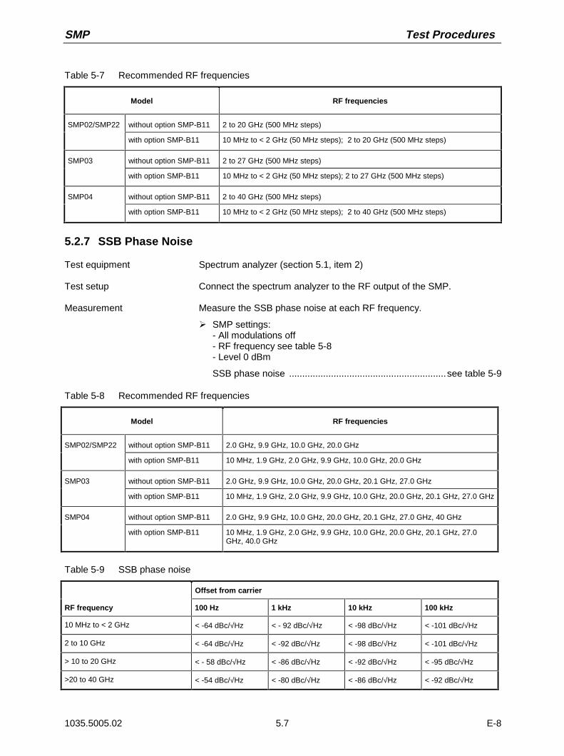
SMP Test Procedures
1035.5005.02 E-85.7
Table 5-7 Recommended RF frequencies
Model RF frequencies
SMP02/SMP22 without option SMP-B11 2 to 20 GHz (500 MHz steps)
with option SMP-B11 10 MHz to < 2 GHz (50 MHz steps); 2 to 20 GHz (500 MHz steps)
SMP03 without option SMP-B11 2 to 27 GHz (500 MHz steps)
with option SMP-B11 10 MHz to < 2 GHz (50 MHz steps); 2 to 27 GHz (500 MHz steps)
SMP04 without option SMP-B11 2 to 40 GHz (500 MHz steps)
with option SMP-B11 10 MHz to < 2 GHz (50 MHz steps); 2 to 40 GHz (500 MHz steps)
5.2.7 SSB Phase Noise
Test equipment Spectrum analyzer (section 5.1, item 2)
Test setup Connect the spectrum analyzer to the RF output of the SMP.
Measurement Measure the SSB phase noise at each RF frequency.
À SMP settings:- All modulations off- RF frequency see table 5-8- Level 0 dBm
SSB phase noise ............................................................see table 5-9
Table 5-8 Recommended RF frequencies
Model RF frequencies
SMP02/SMP22 without option SMP-B11 2.0 GHz, 9.9 GHz, 10.0 GHz, 20.0 GHz
with option SMP-B11 10 MHz, 1.9 GHz, 2.0 GHz, 9.9 GHz, 10.0 GHz, 20.0 GHz
SMP03 without option SMP-B11 2.0 GHz, 9.9 GHz, 10.0 GHz, 20.0 GHz, 20.1 GHz, 27.0 GHz
with option SMP-B11 10 MHz, 1.9 GHz, 2.0 GHz, 9.9 GHz, 10.0 GHz, 20.0 GHz, 20.1 GHz, 27.0 GHz
SMP04 without option SMP-B11 2.0 GHz, 9.9 GHz, 10.0 GHz, 20.0 GHz, 20.1 GHz, 27.0 GHz, 40 GHz
with option SMP-B11 10 MHz, 1.9 GHz, 2.0 GHz, 9.9 GHz, 10.0 GHz, 20.0 GHz, 20.1 GHz, 27.0GHz, 40.0 GHz
Table 5-9 SSB phase noise
Offset from carrier
RF frequency 100 Hz 1 kHz 10 kHz 100 kHz
10 MHz to < 2 GHz < -64 dBc/√Hz < - 92 dBc/√Hz < -98 dBc/√Hz < -101 dBc/√Hz
2 to 10 GHz < -64 dBc/√Hz < -92 dBc/√Hz < -98 dBc/√Hz < -101 dBc/√Hz
> 10 to 20 GHz < - 58 dBc/√Hz < -86 dBc/√Hz < -92 dBc/√Hz < -95 dBc/√Hz
>20 to 40 GHz < -54 dBc/√Hz < -80 dBc/√Hz < -86 dBc/√Hz < -92 dBc/√Hz
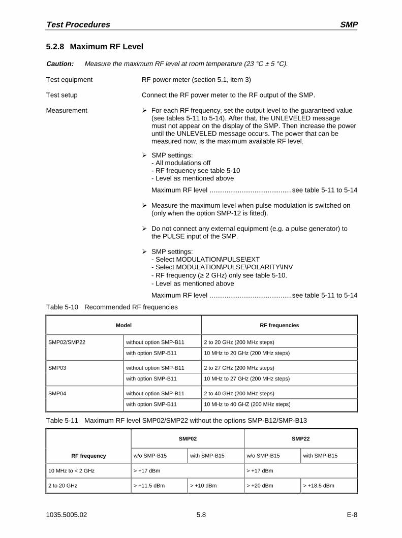
Test Procedures SMP
1035.5005.02 E-85.8
5.2.8 Maximum RF Level
Caution: Measure the maximum RF level at room temperature (23 °C ± 5 °C).
Test equipment RF power meter (section 5.1, item 3)
Test setup Connect the RF power meter to the RF output of the SMP.
Measurement À For each RF frequency, set the output level to the guaranteed value(see tables 5-11 to 5-14). After that, the UNLEVELED messagemust not appear on the display of the SMP. Then increase the poweruntil the UNLEVELED message occurs. The power that can bemeasured now, is the maximum available RF level.
À SMP settings:- All modulations off- RF frequency see table 5-10- Level as mentioned above
Maximum RF level ............................................see table 5-11 to 5-14
À Measure the maximum level when pulse modulation is switched on(only when the option SMP-12 is fitted).
À Do not connect any external equipment (e.g. a pulse generator) tothe PULSE input of the SMP.
À SMP settings:- Select MODULATION\PULSE\EXT- Select MODULATION\PULSE\POLARITY\INV- RF frequency (≥ 2 GHz) only see table 5-10.- Level as mentioned above
Maximum RF level ............................................see table 5-11 to 5-14
Table 5-10 Recommended RF frequencies
Model RF frequencies
SMP02/SMP22 without option SMP-B11 2 to 20 GHz (200 MHz steps)
with option SMP-B11 10 MHz to 20 GHz (200 MHz steps)
SMP03 without option SMP-B11 2 to 27 GHz (200 MHz steps)
with option SMP-B11 10 MHz to 27 GHz (200 MHz steps)
SMP04 without option SMP-B11 2 to 40 GHz (200 MHz steps)
with option SMP-B11 10 MHz to 40 GHZ (200 MHz steps)
Table 5-11 Maximum RF level SMP02/SMP22 without the options SMP-B12/SMP-B13
SMP02 SMP22
RF frequency w/o SMP-B15 with SMP-B15 w/o SMP-B15 with SMP-B15
10 MHz to < 2 GHz > +17 dBm > +17 dBm
2 to 20 GHz > +11.5 dBm > +10 dBm > +20 dBm > +18.5 dBm
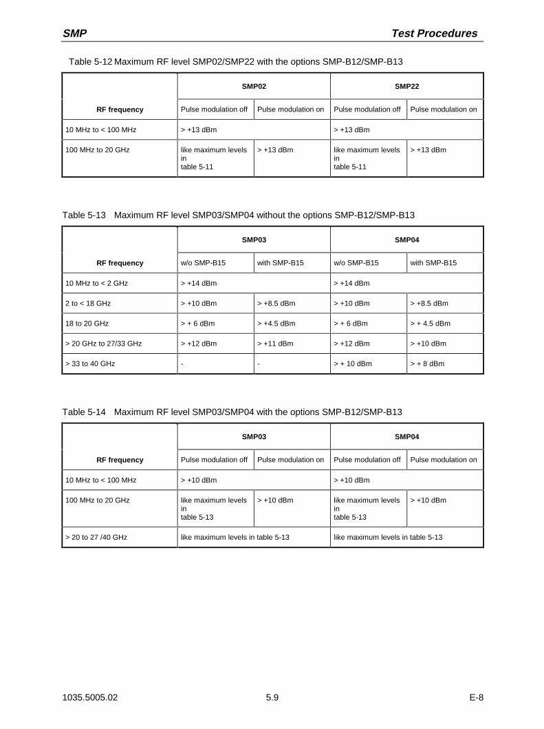
SMP Test Procedures
1035.5005.02 E-85.9
Table 5-12 Maximum RF level SMP02/SMP22 with the options SMP-B12/SMP-B13
SMP02 SMP22
RF frequency Pulse modulation off Pulse modulation on Pulse modulation off Pulse modulation on
10 MHz to < 100 MHz > +13 dBm > +13 dBm
100 MHz to 20 GHz like maximum levelsintable 5-11
> +13 dBm like maximum levelsintable 5-11
> +13 dBm
Table 5-13 Maximum RF level SMP03/SMP04 without the options SMP-B12/SMP-B13
SMP03 SMP04
RF frequency w/o SMP-B15 with SMP-B15 w/o SMP-B15 with SMP-B15
10 MHz to < 2 GHz > +14 dBm > +14 dBm
2 to < 18 GHz > +10 dBm > +8.5 dBm > +10 dBm > +8.5 dBm
18 to 20 GHz > + 6 dBm > +4.5 dBm > + 6 dBm > + 4.5 dBm
> 20 GHz to 27/33 GHz > +12 dBm > +11 dBm > +12 dBm > +10 dBm
> 33 to 40 GHz - - > + 10 dBm > + 8 dBm
Table 5-14 Maximum RF level SMP03/SMP04 with the options SMP-B12/SMP-B13
SMP03 SMP04
RF frequency Pulse modulation off Pulse modulation on Pulse modulation off Pulse modulation on
10 MHz to < 100 MHz > +10 dBm > +10 dBm
100 MHz to 20 GHz like maximum levelsintable 5-13
> +10 dBm like maximum levelsintable 5-13
> +10 dBm
> 20 to 27 /40 GHz like maximum levels in table 5-13 like maximum levels in table 5-13

Test Procedures SMP
1035.5005.02 E-85.10
5.2.9 RF Level Accuracy
Caution: Measure the level accuracy at room temperature (23 °C ± 5 °C).
Test equipment RF power meter (section 5.1, item 3)
Test setup Connect the RF power meter to the RF output of the SMP.
Measurement À For each RF frequency, set the output level to +3 dBm and measurethe actual level, then do so at -7 dBm.
À SMP settings:- All modulations off- RF frequency see table 5-15- Level +3 dBm, -7 dBm
Level accuracyf < 2 GHz....................................................................... < ±0.6 dB2 to 20 GHz................................................................... < ±0.7 dBf > 20 GHz..................................................................... < ±0.9 dB
À Measure the maximum level when pulse modulation is switched on(only when the option SMP-12 is fitted).
À Do not connect any external equipment (e.g. a pulse generator) tothe PULSE input of the SMP.
À SMP settings:- Select MODULATION\PULSE\EXT- Select MODULATION\PULSE\POLARITY\INV- RF frequency (≥ 2 GHz only) see table 5-15.- Level +3 dBm, -7 dBm
Level accuracy .............................. same as with pulse modulation off
Table 5-15 Recommended RF frequencies
Model RF frequencies
SMP02/SMP22 without option SMP-B11 2 to 20 GHz (200 MHz steps)
with option SMP-B11 10 MHz to 20 GHz (200 MHz steps)
SMP03 without option SMP-B11 2 to 27 GHz (200 MHz steps)
with option SMP-B11 10 MHz to 27 GHz (200 MHz steps)
SMP04 without option SMP-B11 2 to 40 GHz (200 MHz steps)
with option SMP-B11 10 MHz to 40 GHz (200 MHz steps)
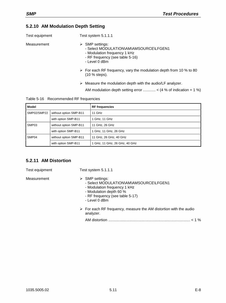
SMP Test Procedures
1035.5005.02 E-85.11
5.2.10 AM Modulation Depth Setting
Test equipment Test system 5.1.1.1
Measurement À SMP settings:- Select MODULATION\AM\AMSOURCE\LFGEN1- Modulation frequency 1 kHz- RF frequency (see table 5-16)- Level 0 dBm
À For each RF frequency, vary the modulation depth from 10 % to 80(10 % steps).
À Measure the modulation depth with the audio/LF analyzer.
AM modulation depth setting error ............ < (4 % of indication + 1 %)
Table 5-16 Recommended RF frequencies
Model RF frequencies
SMP02/SMP22 without option SMP-B11 11 GHz
with option SMP-B11 1 GHz, 11 GHz
SMP03 without option SMP-B11 11 GHz, 26 GHz
with option SMP-B11 1 GHz, 11 GHz, 26 GHz
SMP04 without option SMP-B11 11 GHz, 26 GHz, 40 GHz
with option SMP-B11 1 GHz, 11 GHz, 26 GHz, 40 GHz
5.2.11 AM Distortion
Test equipment Test system 5.1.1.1
Measurement À SMP settings:- Select MODULATION\AM\AMSOURCE\LFGEN1- Modulation frequency 1 kHz- Modulation depth 60 %- RF frequency (see table 5-17)- Level 0 dBm
À For each RF frequency, measure the AM distortion with the audioanalyzer.
AM distortion .............................................................................. < 1 %

Test Procedures SMP
1035.5005.02 E-85.12
Table 5-17 Recommended RF frequencies
Model RF frequencies
SMP02/SMP22 without option SMP-B11 2 GHz, 9.9 GHz, 10 GHz, 20 GHz
with option SMP-B11 10 MHz, 1 GHz, 1.9 GHz,2 GHz, 9.9 GHz, 10 GHz, 20 GHz
SMP03 without option SMP-B11 2 GHz, 9.9 GHz, 10 GHz, 20 GHz, 21 GHz, 26 GHz
with option SMP-B11 10 MHz, 1 GHz, 1.9 GHz, 2 GHz, 9.9 GHz, 10 GHz, 20 GHz, 26 GHz
SMP04 without option SMP-B11 2 GHz, 9.9 GHz, 10 GHz, 20 GHz, 21 GHz, 26 GHz, 40 GHz
with option SMP-B11 10 MHz, 1 GHz, 1.9 GHz, 2 GHz, 9.9 GHz, 10 GHz, 20 GHz, 26 GHz, 40 GHz
5.2.12 AM Frequency Response
Test equipment Test system 5.1.1.1
Measurement À SMP settings:- Select MODULATION\AM\AMSOURCE\EXT1- Modulation depth 60 %- RF frequency see table 5-18- Level 0 dBm
À Modulation analyzer settings (LF generator):- LF frequency see table (5-19)- Generator level 1 Vpeak
À For each RF frequency, vary the LF frequency as shown intable (5-19)
À Measure the modulation depth with the audio/LF analyzer.
AM frequency response (1 dB)f < 2 GHz................................................................. DC to 10 kHzf ≥ 2 GHz................................................................. DC to 50 kHz
AM frequency response (3 dB)..................................... DC to 100 kHz
Table 5-18 Recommended RF frequencies
Model RF frequencies
SMP02/SMP22 without option SMP-B11
11 GHz
with option SMP-B11 1 GHz, 11 GHz
SMP03 without option SMP-B11
11 GHz, 26 GHz
with option SMP-B11 1 GHz, 11 GHz, 26 GHz
SMP04 without option SMP-B11
11 GHz, 26 GHz, 40 GHz
with option SMP-B11 1 GHz, 11 GHz, 26 GHz, 40 GHz
Table 5-19 Recommended LF frequencies
RF frequency LF frequencies
f < 2 GHz (DC), 10 Hz, 30 Hz, 100 Hz, 300 Hz, 1 kHz, 3 kHz, 10 kHz, 30 kHz, 100 kHz
f ≥ 2 GHz (DC), 10 Hz, 30 Hz, 100 Hz, 300 Hz, 1 kHz, 3 kHz, 10 kHz, 30 kHz, 50 kHz, 100 kHz

SMP Test Procedures
1035.5005.02 E-85.13
5.2.13 Amplitude Shift Keying (ASK)
Test equipment Test system 5.1.1.1
Measurement À SMP settings:- Select DIGITAL MOD\ASK\SOURCE\EXT1- Modulation depth 80 %- RF frequency see table 5-20- Level 0 dBm
À Audio analyzer settings:- Modulation frequency 1 kHz (squarewave)- Generator TTL level
À For each RF frequency, measure the modulation depth with themodulation analyzer
Modulation depth setting error........ < ± 10 %(absolute value <± 8 %!)
Table 5-20 Recommended RF frequencies
Model RF frequencies
SMP02/SMP22 2 GHz, 20 GHz
SMP03 2 GHz, 20 GHz, 21 GHz, 26 GHz
SMP04 2 GHz, 20 GHz, 21 GHz, 26 GHz, 40 GHz
5.2.14 FM Deviation Setting
Test equipment Test system 5.1.1.1
Measurement À SMP settings:- Select MODULATION\FM\FM1 SOURCE\EXT1- RF frequency (see table 5-21)- Level 0 dBm
À Audio/LF analyzer settings:- Modulation frequency 100 kHz- Generator level 1 Vpeak
À SMP settings:- Select MODULATION\FM\MODE\LOCKED- FM deviation 500 kHz
À For each RF frequency, measure the FM deviation with the audioanalyzer.
FM deviation setting error..................................... < 10 % of indication
À SMP setting:- Select MODULATION\FM\MODE\UNLOCKED
À For each RF frequency, measure the FM deviation with the audio/LFanalyzer. Because in the UNLOCKED mode the frequency the SMP
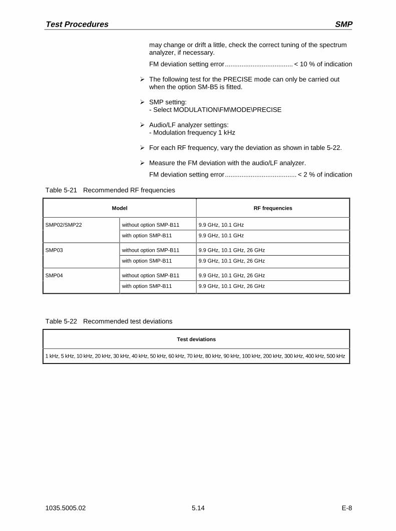
Test Procedures SMP
1035.5005.02 E-85.14
may change or drift a little, check the correct tuning of the spectrumanalyzer, if necessary.
FM deviation setting error..................................... < 10 % of indication
À The following test for the PRECISE mode can only be carried outwhen the option SM-B5 is fitted.
À SMP setting:- Select MODULATION\FM\MODE\PRECISE
À Audio/LF analyzer settings:- Modulation frequency 1 kHz
À For each RF frequency, vary the deviation as shown in table 5-22.
À Measure the FM deviation with the audio/LF analyzer.
FM deviation setting error....................................... < 2 % of indication
Table 5-21 Recommended RF frequencies
Model RF frequencies
SMP02/SMP22 without option SMP-B11 9.9 GHz, 10.1 GHz
with option SMP-B11 9.9 GHz, 10.1 GHz
SMP03 without option SMP-B11 9.9 GHz, 10.1 GHz, 26 GHz
with option SMP-B11 9.9 GHz, 10.1 GHz, 26 GHz
SMP04 without option SMP-B11 9.9 GHz, 10.1 GHz, 26 GHz
with option SMP-B11 9.9 GHz, 10.1 GHz, 26 GHz
Table 5-22 Recommended test deviations
Test deviations
1 kHz, 5 kHz, 10 kHz, 20 kHz, 30 kHz, 40 kHz, 50 kHz, 60 kHz, 70 kHz, 80 kHz, 90 kHz, 100 kHz, 200 kHz, 300 kHz, 400 kHz, 500 kHz

SMP Test Procedures
1035.5005.02 E-85.15
5.2.15 FM Distortion
Test equipment Test system 5.1.1.1
Measurement À SMP settings:- Select MODULATION\FM\FM1 SOURCE\EXT1- RF frequency (see table 5-23)- Level 0 dBm
À Audio/LF analyzer settings:- Modulation frequency 50 kHz- Generator level 1 Vpeak
À SMP settings:- Select MODULATION\FM\MODE\LOCKED- FM deviation 500 kHz
À For each RF frequency, measure the FM distortion with the audioanalyzer.
FM distortion............................................................................ < 0.5 %
À SMP setting:- Select MODULATION\FM\MODE\UNLOCKED
À For each RF frequency, measure the FM distortion with the audio/LFanalyzer. Because in the UNLOCKED mode the frequency the SMPmay change or drift a little bit, check the correct tuning of thespectrum analyzer, if necessary.
FM distortion............................................................................ < 0.5 %
À The following test for the PRECISE mode can only be carried outwhen the option SM-B5 is fitted.
À SMP setting:- Select MODULATION\FM\MODE\PRECISE
À For each RF frequency, measure the FM distortion with the audioanalyzer.
FM distortion............................................................................ < 0.5 %
Table 5-23 Recommended RF frequencies
Model RF frequencies
SMP02/SMP22 without option SMP-B11 9.9 GHz, 10.1 GHz
with option SMP-B11 9.9 GHz, 10.1 GHz
SMP03 without option SMP-B11 9.9 GHz, 10.1 GHz, 26 GHz
with option SMP-B11 9.9 GHz, 10.1 GHz, 26 GHz
SMP04 without option SMP-B11 9.9 GHz, 10.1 GHz, 26 GHz
with option SMP-B11 9.9 GHz, 10.1 GHz, 26 GHz

Test Procedures SMP
1035.5005.02 E-85.16
5.2.16 FM Frequency Response
Test equipment Test system 5.1.1.1
Measurement À SMP settings:- Select MODULATION\FM\FM1 SOURCE\EXT1- RF frequency see table 5-24- Level 0 dBm
À Audio/LF analyzer settings:- LF frequency see table 5-25- Generator TTL level
À SMP settings:- Select MODULATION\FM\MODE\LOCKED- FM deviation 100 kHz
À For each RF frequency, vary the LF frequency as shown in table 5-25.
À Measure the FM frequency response with the modulation analyzer.
FM frequency response20 kHz to 1 MHz ................................................................ < 5 dB
À SMP setting:- Select MODULATION\FM\MODE\UNLOCKED- FM deviation 10 MHz
À For each RF frequency, vary the LF frequency as shown in table 5-25. Because in the UNLOCKED mode the frequency of the SMPmay change or drift a little, check the correct tuning of the spectrumanalyzer, if necessary.
À Measure the FM frequency response with the modulation analyzer.
FM frequency response10 Hz (DC) to < 50 kHz...................................................... < 1 dB50 kHz to 1 MHz ................................................................ < 5 dB
À The following test for the PRECISE mode can only be carried outwhen the option SM-B5 is fitted.
À SMP setting:- Select MODULATION\FM\MODE\PRECISE- FM deviation 100 kHz
À For each RF frequency, vary the LF frequency as shown in table 5-25.
À Measure the FM frequency response with the modulation analyzer.
FM frequency response10 Hz (DC) to < 50 kHz................................................... < 0.5 dB50 kHz to 1 MHz ................................................................ < 4 dB

SMP Test Procedures
1035.5005.02 E-85.17
Table 5-24 Recommended RF frequencies
Model RF frequencies
SMP02/SMP22 without option SMP-B11 9.9 GHz, 10.1 GHz
with option SMP-B11 9.9 GHz, 10.1 GHz
SMP03 without option SMP-B11 9.9 GHz, 10.1 GHz, 26 GHz
with option SMP-B11 9.9 GHz, 10.1 GHz, 26 GHz
SMP04 without option SMP-B11 9.9 GHz, 10.1 GHz, 26 GHz
with option SMP-B11 9.9 GHz, 10.1 GHz, 26 GHz
Table 5-25 Recommended LF frequencies
FM mode LF Frequencies
LOCKED 20 kHz, 40 kHz, 50 kHz, 60 kHz, 70 kHz, 80 kHz, 90 kHz, 100 kHz, 200 kHz, 300 kHz, 400kHz, 500 kHz, 600 kHz, 700 kHz, 800 kHz, 900 kHz, 1 MHz
UNLOCKED, PRECISE 10 Hz, 30 Hz, 100 Hz, 1 kHz, 10 kHz, 20 kHz, 30 kHz, 40 kHz, 50 kHz, 60 kHz, 80 kHz, 100kHz, 200 kHz, 300 kHz, 400 kHz, 500 kHz, 600 kHz, 700 kHz, 800 kHz, 900 kHz, 1 MHz
5.2.17 Frequency Shift Keying (FSK)
Test equipment Test system 5.1.1.1
Measurement À SMP settings:- Select DIGITAL MOD\FSK\SOURCE\EXT1- Deviation 10 MHz- RF frequency 6 GHz- Level 0 dBm
À Audio/LF analyzer settings:- Modulation frequency 100 kHz (squarewave)- Generator level 1 Vpeak
À Measure the deviation with the modulation analyzer.
Deviation setting error ........................................................... < ± 10 %
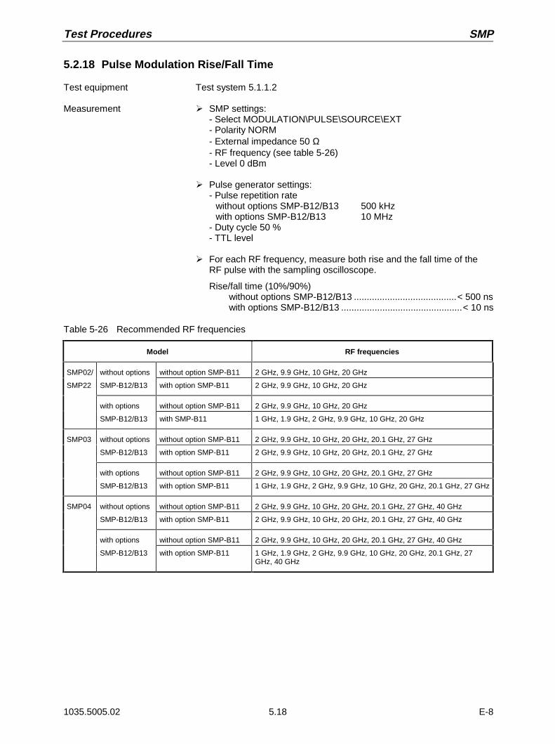
Test Procedures SMP
1035.5005.02 E-85.18
5.2.18 Pulse Modulation Rise/Fall Time
Test equipment Test system 5.1.1.2
Measurement À SMP settings:- Select MODULATION\PULSE\SOURCE\EXT- Polarity NORM- External impedance 50 Ω- RF frequency (see table 5-26)- Level 0 dBm
À Pulse generator settings:- Pulse repetition rate
without options SMP-B12/B13 500 kHzwith options SMP-B12/B13 10 MHz
- Duty cycle 50 %- TTL level
À For each RF frequency, measure both rise and the fall time of theRF pulse with the sampling oscilloscope.
Rise/fall time (10%/90%)without options SMP-B12/B13 ........................................< 500 nswith options SMP-B12/B13 ...............................................< 10 ns
Table 5-26 Recommended RF frequencies
Model RF frequencies
SMP02/ without options without option SMP-B11 2 GHz, 9.9 GHz, 10 GHz, 20 GHz
SMP22 SMP-B12/B13 with option SMP-B11 2 GHz, 9.9 GHz, 10 GHz, 20 GHz
with options without option SMP-B11 2 GHz, 9.9 GHz, 10 GHz, 20 GHz
SMP-B12/B13 with SMP-B11 1 GHz, 1.9 GHz, 2 GHz, 9.9 GHz, 10 GHz, 20 GHz
SMP03 without options without option SMP-B11 2 GHz, 9.9 GHz, 10 GHz, 20 GHz, 20.1 GHz, 27 GHz
SMP-B12/B13 with option SMP-B11 2 GHz, 9.9 GHz, 10 GHz, 20 GHz, 20.1 GHz, 27 GHz
with options without option SMP-B11 2 GHz, 9.9 GHz, 10 GHz, 20 GHz, 20.1 GHz, 27 GHz
SMP-B12/B13 with option SMP-B11 1 GHz, 1.9 GHz, 2 GHz, 9.9 GHz, 10 GHz, 20 GHz, 20.1 GHz, 27 GHz
SMP04 without options without option SMP-B11 2 GHz, 9.9 GHz, 10 GHz, 20 GHz, 20.1 GHz, 27 GHz, 40 GHz
SMP-B12/B13 with option SMP-B11 2 GHz, 9.9 GHz, 10 GHz, 20 GHz, 20.1 GHz, 27 GHz, 40 GHz
with options without option SMP-B11 2 GHz, 9.9 GHz, 10 GHz, 20 GHz, 20.1 GHz, 27 GHz, 40 GHz
SMP-B12/B13 with option SMP-B11 1 GHz, 1.9 GHz, 2 GHz, 9.9 GHz, 10 GHz, 20 GHz, 20.1 GHz, 27GHz, 40 GHz

SMP Test Procedures
1035.5005.02 E-85.19
5.2.19 Pulse Modulation On /Off Ratio
Test equipment Spectrum analyzer (section 5.1, item 2)
Test setup Connect the spectrum analyzer to the RF output of the SMP.
Measurement À SMP settings:- Select MODULATION\PULSE\SOURCE\EXT- Polarity INV- External impedance 50 Ω- RF frequency (see table 5-27)- Level 0 dBm
À Do not connect any external equipment (e. g. pulse generator) to thePULSE input of the SMP.
À For each RF frequency, measure the output power of the SMP withpulse polarity INV (= RF on) and NORM (= RF off). Calculate theon/off ratio in dB.
On/off ratiowithout options SMP-B12/B13 ......................................... > 50 dBwith options SMP-B12/B13 .............................................. > 80 dB
Table 5-27 Recommended RF frequencies
Model RF frequencies
SMP02/ without options without option SMP-B11
2 GHz, 9.9 GHz, 10 GHz, 20 GHz
SMP22 SMP-B12/B13 with option SMP-B11 2 GHz, 9.9 GHz, 10 GHz, 20 GHz
with options without option SMP-B11
2 GHz, 9.9 GHz, 10 GHz, 20 GHz
SMP-B12/B13 with SMP-B11 1 GHz, 1.9 GHz, 2 GHz, 9.9 GHz, 10 GHz, 20 GHz
SMP03 without options without option SMP-B11
2 GHz, 9.9 GHz, 10 GHz, 20 GHz, 20.1 GHz, 27 GHz
SMP-B12/B13 with option SMP-B11 2 GHz, 9.9 GHz, 10 GHz, 20 GHz, 20.1 GHz, 27 GHz
with options without option SMP-B11
2 GHz, 9.9 GHz, 10 GHz, 20 GHz, 20.1 GHz, 27 GHz
SMP-B12/B13 with option SMP-B11 1 GHz, 1.9 GHz, 2 GHz, 9.9 GHz, 10 GHz, 20 GHz, 20.1 GHz, 27 GHz
SMP04 without options without option SMP-B11
2 GHz, 9.9 GHz, 10 GHz, 20 GHz, 20.1 GHz, 27 GHz, 40 GHz
SMP-B12/B13 with option SMP-B11 2 GHz, 9.9 GHz, 10 GHz, 20 GHz, 20.1 GHz, 27 GHz, 40 GHz
with options without option SMP-B11
2 GHz, 9.9 GHz, 10 GHz, 20 GHz, 20.1 GHz, 27 GHz, 40 GHz
SMP-B12/B13 with option SMP-B11 1 GHz, 1.9 GHz, 2 GHz, 9.9 GHz, 10 GHz, 20 GHz, 20.1 GHz, 27GHz, 40 GHz
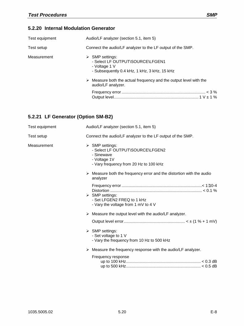
Test Procedures SMP
1035.5005.02 E-85.20
5.2.20 Internal Modulation Generator
Test equipment Audio/LF analyzer (section 5.1, item 5)
Test setup Connect the audio/LF analyzer to the LF output of the SMP.
Measurement À SMP settings:- Select LF OUTPUT\SOURCE\LFGEN1- Voltage 1 V- Subsequently 0.4 kHz, 1 kHz, 3 kHz, 15 kHz
À Measure both the actual frequency and the output level with theaudio/LF analyzer.
Frequency error .......................................................................... < 3 %Output level........................................................................... 1 V ± 1 %
5.2.21 LF Generator (Option SM-B2)
Test equipment Audio/LF analyzer (section 5.1, item 5)
Test setup Connect the audio/LF analyzer to the LF output of the SMP.
Measurement À SMP settings:- Select LF OUTPUT\SOURCE\LFGEN2- Sinewave- Voltage 1V- Vary frequency from 20 Hz to 100 kHz
À Measure both the frequency error and the distortion with the audioanalyzer
Frequency error .......................................................................< 1⋅10-4Distortion ................................................................................. < 0.1 %
À SMP settings:- Set LFGEN2 FREQ to 1 kHz- Vary the voltage from 1 mV to 4 V
À Measure the output level with the audio/LF analyzer.
Output level error...................................................... < ± (1 % + 1 mV)
À SMP settings:- Set voltage to 1 V- Vary the frequency from 10 Hz to 500 kHz
À Measure the frequency response with the audio/LF analyzer.
Frequency responseup to 100 kHz.................................................................. < 0.3 dBup to 500 kHz.................................................................. < 0.5 dB
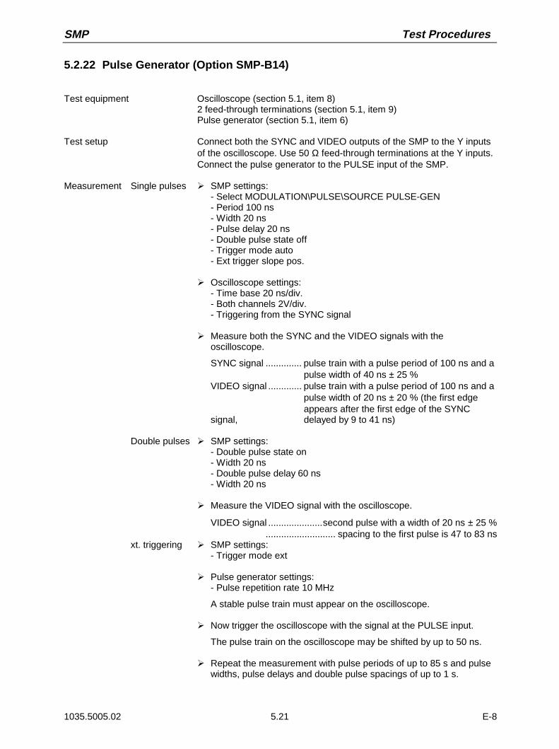
SMP Test Procedures
1035.5005.02 E-85.21
5.2.22 Pulse Generator (Option SMP-B14)
Test equipment Oscilloscope (section 5.1, item 8)2 feed-through terminations (section 5.1, item 9)Pulse generator (section 5.1, item 6)
Test setup Connect both the SYNC and VIDEO outputs of the SMP to the Y inputsof the oscilloscope. Use 50 Ω feed-through terminations at the Y inputs.Connect the pulse generator to the PULSE input of the SMP.
Measurement Single pulses À SMP settings:- Select MODULATION\PULSE\SOURCE PULSE-GEN- Period 100 ns- Width 20 ns- Pulse delay 20 ns- Double pulse state off- Trigger mode auto- Ext trigger slope pos.
À Oscilloscope settings:- Time base 20 ns/div.- Both channels 2V/div.- Triggering from the SYNC signal
À Measure both the SYNC and the VIDEO signals with theoscilloscope.
SYNC signal .............. pulse train with a pulse period of 100 ns and apulse width of 40 ns ± 25 %
VIDEO signal ............. pulse train with a pulse period of 100 ns and apulse width of 20 ns ± 20 % (the first edgeappears after the first edge of the SYNC
signal, delayed by 9 to 41 ns)
Double pulses À SMP settings:- Double pulse state on- Width 20 ns- Double pulse delay 60 ns- Width 20 ns
À Measure the VIDEO signal with the oscilloscope.
VIDEO signal .....................second pulse with a width of 20 ns ± 25 %........................... spacing to the first pulse is 47 to 83 ns
xt. triggering À SMP settings:- Trigger mode ext
À Pulse generator settings:- Pulse repetition rate 10 MHz
A stable pulse train must appear on the oscilloscope.
À Now trigger the oscilloscope with the signal at the PULSE input.
The pulse train on the oscilloscope may be shifted by up to 50 ns.
À Repeat the measurement with pulse periods of up to 85 s and pulsewidths, pulse delays and double pulse spacings of up to 1 s.

Test Procedures SMP
1035.5005.02 E-85.22
5.3 Test Report
ROHDE & SCHWARZ SIGNAL GENERATOR SMP 1035.5005.__
Serial number:
Name:
Date:
Signature:
Table 5-28 Test report
Item Characteristic Measurem.acc. tosection
Min. Actual Max. Unit
1 Display and keyboard 5.2.1 checked ……… − −
2 Frequency setting 5.2.2 checked ……… − −
3 Reference frequency 5.2.3 − ……… − −
4 Suppression of harmonics
a) Pulse mod. off (with/without options SMP-B12/B13)
5.2.4
SMP02f < 1.8 GHzf ≥ 1.8 GHz
−−
………………
-30-40
dBcdBc
SMP22 − ……… -25 dBc
SMP03/SMP04f < 1.8 GHzf ≥ 1.8 GHz
−−
………………
-30-40
dBcdBc
b) Pulse mod. on (only with options SMP-B12/ B13)
− ……… -25 dBc
5 Suppression of subharmonics 5.2.5
SMP03f > 20 GHz − ……… -40 dBc
SMP04f > 20 GHz − ……… -30 dBc
6 Suppression of nonharmonics 5.2.6
f < 2 GHz2 to 20 GHzf > 20 GHz
−−−
………………………
-50-60-54
dBcdBcdBc
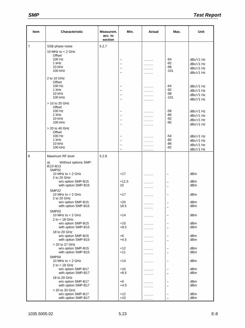
SMP Test Report
1035.5005.02 E-85.23
Item Characteristic Measurem.acc. tosection
Min. Actual Max. Unit
7 SSB phase noise 5.2.7
10 MHz to < 2 GHzOffset100 Hz1 kHz10 kHz100 kHz
−−−−
………………………………
-64-92-98-101
dBc/√1 HzdBc/√1 HzdBc/√1 HzdBc/√1 Hz
2 to 10 GHzOffset100 Hz1 kHz10 kHz100 kHz
−−−−
………………………………
-64-92-98-101
dBc/√1 HzdBc/√1 HzdBc/√1 HzdBc/√1 Hz
> 10 to 20 GHzOffset100 Hz1 kHz10 kHz100 kHz
−−−−
………………………………
-58-86-92-95
dBc/√1 HzdBc/√1 HzdBc/√1 HzdBc/√1 Hz
> 20 to 40 GHzOffset100 Hz1 kHz10 kHz100 kHz
−−−−
………………………………
-54-80-86-92
dBc/√1 HzdBc/√1 HzdBc/√1 HzdBc/√1 Hz
8 Maximum RF level 5.2.8
a) Without options SMP-B12/-B13
SMP0210 MHz to < 2 GHz2 to 20 GHz
w/o option SMP-B15with option SMP-B15
+17
+11.510
………
………………
−
−−
dBm
dBmdBm
SMP2210 MHz to < 2 GHz2 to 20 GHz
w/o option SMP-B15with option SMP-B15
+17
+2018.5
………
………………
−
−−
dBm
dBmdBm
SMP0310 MHz to < 2 GHz +14 ……… − dBm2 to < 18 GHz
w/o option SMP-B15with option SMP-B15
+10+8.5
………………
−−
dBmdBm
18 to 20 GHzw/o option SMP-B15with option SMP-B15
+6+4.5
………………
−−
dBmdBm
> 20 to 27 GHzw/o option SMP-B15with option SMP-B15
+12+11
………………
−−
dBmdBm
SMP0410 MHz to < 2 GHz +14 ……… − dBm2 to < 18 GHz
w/o option SMP-B17with option SMP-B17
+10+8.5
………………
−−
dBmdBm
18 to 20 GHzw/o option SMP-B17with option SMP-B17
+6+4.5
………………
−−
dBmdBm
> 20 to 33 GHzw/o option SMP-B17with option SMP-B17
+12+10
………………
−−
dBmdBm

Test Procedures SMP
1035.5005.02 E-85.24
Item Characteristic Measurem.acc. tosection
Min. Actual Max. Unit
> 33 to 40 GHzw/o option SMP-B17with option SMP-B17
+10+8
………………
−−
dBmdBm
b) With options SMP-B12/ -B13, Pulse mod. off
8
SMP0210 MHz to < 100 MHz100 MHz to < 2 GHz2 to 20 GHz
w/o option SMP-B15with option SMP-B15
+13+17
+11.5+10
………………
………………
−−
−−
dBmdBm
dBmdBm
SMP2210 MHz to < 100 MHz100 MHz to < 2 GHz2 to 20 GHz
w/o option SMP-B15with option SMP-B15
+13+17
+20+18.5
………………
………………
−−
−−
dBmdBm
dBmdBm
SMP0310 MHz to < 100 MHz100 MHz to < 2 GHz2 to < 18 GHz
w/o option SMP-B15with option SMP-B15
18 to 20 GHzw/o option SMP-B15with option SMP-B15
> 20 to 27 GHzw/o option SMP-B15with option SMP-B15
+10+14
+10+8.5
+6+4.5
1211
………………
………………
………………
………………
−−
−−−−
−−
dBmdBm
dBmdBm
dBmdBm
dBmdbBm
SMP0410 MHz to < 100 MHz100 MHz to < 2 GHz2 to < 18 GHz
w/o option SMP-B17with option SMP-B17
18 to 20 GHzw/o option SMP-B17with option SMP-B17
> 20 to 33 GHzw/o option SMP-B17with option SMP-B17
> 33 to 40 GHzw/o option SMP-B17with option SMP-B17
+10+14
+10+8.5
+6+4.5
1210
+10+8
………………
………………
………………
………………
………………
−−
−−
−−
−−
−−
dBmdBm
dBmdBm
dBmdBm
dBmdBm
dBmdBm
c) With options SMP-B12/ -B13, Pulse mod. on
SMP02/SMP2210 MHz to 20 MHz +13 ……… − dBm
SMP0310 MHz to 20 GHz> 20 to 27 GHz
w/o option SMP-B15with option SMP-B15
+10
+12+11
………
………………
−
−−
dBm
dBmdBm

SMP Test Report
1035.5005.02 E-85.25
Item Characteristic Measurem.acc. tosection
Min. Actual Max. Unit
SMP0410 MHz to 20 GHz> 20 to 33 GHz
w/o option SMP-B17with option SMP-B17
> 33 to 40 GHzw/o option SMP-B17with option SMP-B17
+10
+12+10
+10+8
………
………………
………………
−
−−
−−
dBm
dBmdBm
dBmdBm
9 RF level accuracyf < 2 GHz2 to 20 GHzf > 20 GHz
5.2.9-0.6-0.7-0.9
………………………
+0.6+0.7+0.9
dBdBdB
10 AM modulation depth setting10 %20 %30 %40 %50 %60 %70 %80 %90 %
5.2.108.618.227.837.44756.666.275.885.4
………………………………………………………………………
11.421.832.242.65363.473.884.294.6
%%%%%%%%%
11 AM distortion 5.2.11 − ……… 1 %
12 AM frequency responsef < 2 GHz, DC to 10 kHzf ≥ 2 GHz, DC to 50 kHzDC to 100 kHz
5.2.12−−−
………………………
113
dBdBdB
13 Amplitude shift keyingdepth 80 %
5.2.1372 ……… 88 %
14 FM deviation setting 5.2.14LOCKEDUNLOCKEDPRECISE
1 kHz5 kHz
10 kHz20 kHz30 kHz40 kHz50 kHz60 kHz70 kHz80 kHz90 kHz
100 kHz200 kHz300 kHz400 kHz500 kHz
450450
0.984.99.819.629.439.24958 868.678.488.298196294392490
………………………………………………………………………………………………………………………………………………
550550
1.025.110.220.430.640.85161.271.481.691.8102204306408510
kHzkHz
kHzkHzkHzkHzkHzkHzkHzkHzkHzkHzkHzkHzkHzkHzkHzkHz
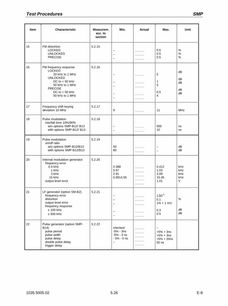
Test Procedures SMP
1035.5005.02 E-85.26
Item Characteristic Measurem.acc. tosection
Min. Actual Max. Unit
15 FM distortionLOCKEDUNLOCKEDPRECISE
5.2.15−−−
………………………
0.50.50.5
%%%
16 FM frequency responseLOCKED
20 kHz to 1 MHzUNLOCKED
DC to < 50 kHz50 kHz to 1 MHz
PRECISEDC to < 50 kHz50 kHz to 1 MHz
5.2.16
−
−−
−−
………
………………
………………
5
15
0.54
dB
dBdB
dBdB
17 Frequency shift keyingdeviation 10 MHz
5.2.179 ……… 11 MHz
18 Pulse modulationrise/fall time 10%/90%
w/o options SMP-B12/ B13with options SMP-B12/ B13
5.2.18
−−
………………
50010
nsns
19 Pulse modulationon/off ratio
w/o options SMP-B12/B13with options SMP-B12/B13
5.2.19
5080
………………
−−
dBdB
20 Internal modulation generatorfrequency error
0.4 kHz1 kHz3 kHz
15 kHzoutput level error
5.2.20
0.3880.972.910.9914.55
………………………………………
0.4121.033.0915.451.01
kHzkHzkHzkHzV
21 LF generator (option SM-B2)frequency errordistortionoutput level errorfrequency response
≤ 100 kHz≤ 500 kHz
5.2.21−−−
−−
………………………
………………
1⋅10-4
0.11% + 1 mV
0.30.5
%
dBdB
22 Pulse generator (option SMP-B14)
pulse periodpulse widthpulse delaydouble pulse delaytrigger delay
5.2.22checked-5% - 3ns-5% - 3 ns- 5% - 5 ns−
………………………………………
−+5% + 3ns+5% + 3ns+5% + 20ns50 ns
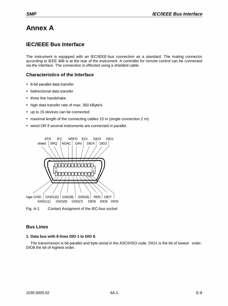
SMP IEC/IEEE Bus Interface
1035.5005.02 6A.1 E-8
Annex A
IEC/IEEE Bus Interface
The instrument is equipped with an IEC/IEEE-bus connection as a standard. The mating connectoraccording to IEEE 488 is at the rear of the instrument. A controller for remote control can be connectedvia the interface. The connection is effected using a shielded cable.
Characteristics of the Interface
ì 8-bit parallel data transfer
ì bidirectional data transfer
ì three line handshake
ì high data transfer rate of max. 350 kByte/s
ì up to 15 devices can be connected
ì maximal length of the connecting cables 15 m (single connection 2 m)
ì wired OR if several instruments are connected in parallel.
12 11324
shield SRQ NDAC DAV DIO4 DIO2
logic GND GND(10) GND(8) GND(6) REN DIO7 GND(11) GND(9) GND(7) DIO8 DIO6 DIO5
ATN IFC NRFD EOI DIO3 DIO1
Fig. A-1 Contact Assigment of the IEC-bus socket
Bus Lines
1. Data bus with 8 lines DIO 1 to DIO 8.
The transmission is bit-parallel and byte-serial in the ASCII/ISO code. DIO1 is the bit of lowest order,DIO8 the bit of highest order.
IEC/IEEE Bus Interface SMP
1035.5005.02 6A.2 E-8
2. Control bus with 5 lines.
IFC (Interface Clear),active low resets the interfaces of the instruments connected to the default setting.
ATN (Attention),active low signals the transmission of interface messagesinactive high signals the transmission of device-dependent messages.
SRQ (Service Request),active low enables a device connected to send a service request to the controller.
REN (Remote Enable),active low permits the switchover to remote control.
EOI (End or Identify),has two functions in connection with ATN:active low marks the end of data transmission with ATN=highactive low triggers a parallel poll with ATN=low.
3. Handshake bus with three lines.
DAV (Data Valid),active low signals a valid data byte on the data bus.
NRFD (Not Ready For Data),active low signals that one of the device connected is not ready for data transfer.
NDAC (Not Data Accepted),active low as long as the instrument connected is accepting the data present on the data bus.
Interface Functions
Instruments which can be remote-controlled via IEC bus can be equipped with different interfacefunctions. Table A-1 lists the interface functions appropriate for the instrument.
Table A-1 Interface function
Controlcharacter
Interface function
SH1 Handshake source function (source handshake)
AH1 Handshake drain function (acceptor handshake)
L4 Listener function.
T6 Talker function, ability to respond to serial poll
SR1 Service request function (Service Request)
PP1 Parallel poll function
RL1 Remote/Local switchover function
DC1 Resetting function (Device Clear)
DT1 Trigger function (Device Trigger)

SMP IEC/IEEE Bus Interface
1035.5005.02 6A.3 E-8
Interface Messages
Interface messages are transmitted to the instrument on the data lines, with the attention line beingactive (LOW). They serve to communicate between instrument and controller.
Universal Commands
The universal commands are encoded in the range 10 through 1F hex. They are effective for allinstruments connected to the bus without addressing them before.
Tabelle A-2 Universal Commands
Command QuickBASIC commandl Effect on the instrument
DCL (Device Clear) IBCMD (controller%, CHR$(20)) Aborts the processing of the commands just receivedand sets the command processing software to adefined initial state. Does not change the instrumentsetting.
IFC (Interface Clear) IBSIC (controller%) Resets the interfaces to the default setting.
LLO (Local Lockout) IBCMD (controller%, CHR$(17)) The LOC/IEC ADDR key is disabled.
SPE (Serial Poll Enable) IBCMD (controller%, CHR$(24)) Ready for serial poll
SPD (Serial Poll Disable) IBCMD (controller%, CHR$(25)) End of serial poll
PPU Parallel Poll Unconfigure) IBCMD (controller%, CHR$(21)) End of the parallel-poll polling state
Addressed Commands
The addressed commands are encoded in the range 00 through 0F hex. They are only effective forinstruments addressed as listeners.
Table A-3 Addressed Commands
Command QuickBASIC commandl Effect on the instrument
SDC (Selected DeviceClear)
IBCLR (device%) Aborts the processing of the commands just receivedand sets the command processing software to adefined initial state. Does not change the instrumentsetting.
GET (Group ExecuteTrigger)
IBTRG (device%) Triggers a previously active device function (eg asweep). The effect of the command is the same aswith that of a pulse at the external trigger signal input.
GTL (Go to Local) IBLOC (device%) Transition to the "Local" state (manual control)
PPC (Parallel PollConfigure)
IBPPC (device%, data%) Configure instrument for parallel poll. TheQuickBASIC command additionally executes PPE /PPD.
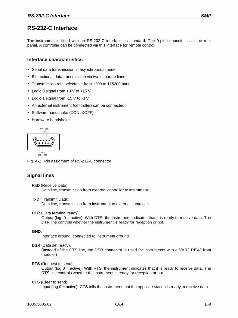
RS-232-C Interface SMP
1035.5005.02 6A.4 E-8
RS-232-C Interface
The instrument is fitted with an RS-232-C interface as standard. The 9-pin connector is at the rearpanel. A controller can be connected via this interface for remote control.
Interface characteristics
ì Serial data transmission in asynchronous mode
ì Bidirectional data transmission via two separate lines
ì Transmission rate selectable from 1200 to 115200 baud
ì Logic 0 signal from +3 V to +15 V
ì Logic 1 signal from -15 V to -3 V
ì An external instrument (controller) can be connected
ì Software handshake (XON, XOFF)
ì Hardware handshake
Fig. A-2 Pin assigment of RS-232-C connector
Signal lines
RxD (Receive Data),Data line, transmission from external controller to instrument.
TxD (Transmit Data),Data line, transmission from instrument to external controller.
DTR (Data terminal ready),Output (log. 0 = active). With DTR, the instrument indicates that it is ready to receive data. TheDTR line controls whether the instrument is ready for reception or not.
GND,Interface ground, connected to instrument ground.
DSR (Data set ready),(Instead of the CTS line, the DSR connector is used for instruments with a VAR2 REV3 frontmodule.)
RTS (Request to send),Output (log 0 = active). With RTS, the instrument indicates that it is ready to receive data. TheRTS line controls whether the instrument is ready for reception or not.
CTS (Clear to send),Input (log 0 = active). CTS tells the instrument that the opposite station is ready to receive data.
RxD DTR
1
6
5
9
TxD
DSR CTS
RTS
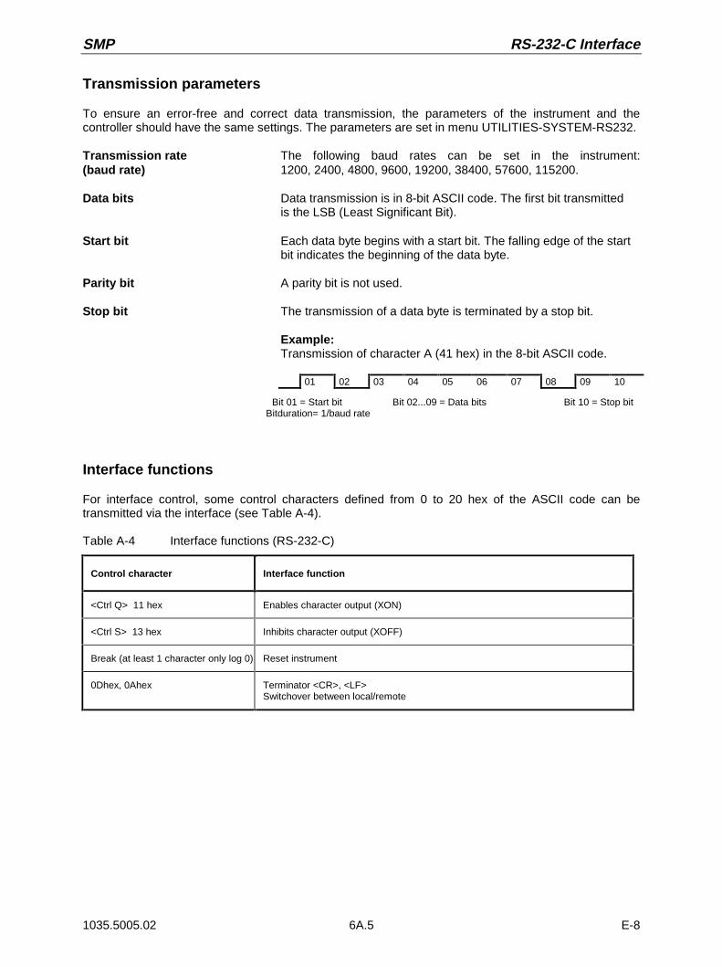
SMP RS-232-C Interface
1035.5005.02 6A.5 E-8
Transmission parameters
To ensure an error-free and correct data transmission, the parameters of the instrument and thecontroller should have the same settings. The parameters are set in menu UTILITIES-SYSTEM-RS232.
Transmission rate The following baud rates can be set in the instrument:(baud rate) 1200, 2400, 4800, 9600, 19200, 38400, 57600, 115200.
Data bits Data transmission is in 8-bit ASCII code. The first bit transmitted is the LSB (Least Significant Bit).
Start bit Each data byte begins with a start bit. The falling edge of the start bit indicates the beginning of the data byte.
Parity bit A parity bit is not used.
Stop bit The transmission of a data byte is terminated by a stop bit.
Example:Transmission of character A (41 hex) in the 8-bit ASCII code.
01 02 03 04 05 06 07 08 09 10
Bit 01 = Start bit Bit 02...09 = Data bits Bit 10 = Stop bitBitduration= 1/baud rate
Interface functions
For interface control, some control characters defined from 0 to 20 hex of the ASCII code can betransmitted via the interface (see Table A-4).
Table A-4 Interface functions (RS-232-C)
Control character Interface function
<Ctrl Q> 11 hex Enables character output (XON)
<Ctrl S> 13 hex Inhibits character output (XOFF)
Break (at least 1 character only log 0) Reset instrument
0Dhex, 0Ahex Terminator <CR>, <LF>Switchover between local/remote
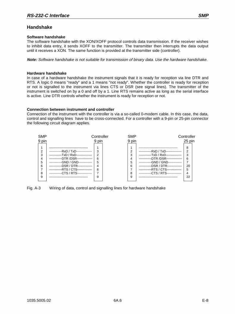
RS-232-C Interface SMP
1035.5005.02 6A.6 E-8
Handshake
Software handshakeThe software handshake with the XON/XOFF protocol controls data transmission. If the receiver wishesto inhibit data entry, it sends XOFF to the transmitter. The transmitter then interrupts the data outputuntil it receives a XON. The same function is provided at the transmitter side (controller).
Note: Software handshake is not suitable for transmission of binary data. Use the hardware handshake.
Hardware handshakeIn case of a hardware handshake the instrument signals that it is ready for reception via line DTR andRTS. A logic 0 means "ready" and a 1 means "not ready". Whether the controller is ready for receptionor not is signalled to the instrument via lines CTS or DSR (see signal lines). The transmitter of theinstrument is switched on by a 0 and off by a 1. Line RTS remains active as long as the serial interfaceis active. Line DTR controls whether the instrument is ready for reception or not.
Connection between instrument and controllerConnection of the instrument with the controller is via a so-called 0-modem cable. In this case, the data,control and signalling lines have to be cross-connected. For a controller with a 9-pin or 25-pin connectorthe following circuit diagram applies.
SMP Controller SMP Controller9 pin 9 pin 9 pin 25 pin
123456789
-------------------------------------------------RxD / TxD---------------------------TxD / RxD---------------------------DTR /DSR---------------------------GND / GND-------------------------DSR / DTR--------------------------RTS / CTS--------------------------CTS / RTS---------------------------------------------------
132654879
123456789
-------------------------------------------------RxD / TxD---------------------------TxD / RxD---------------------------DTR /DSR---------------------------GND / GND-------------------------DSR / DTR--------------------------RTS / CTS--------------------------CTS / RTS---------------------------------------------------
82367205422
Fig. A-3 Wiring of data, control and signalling lines for hardware handshake
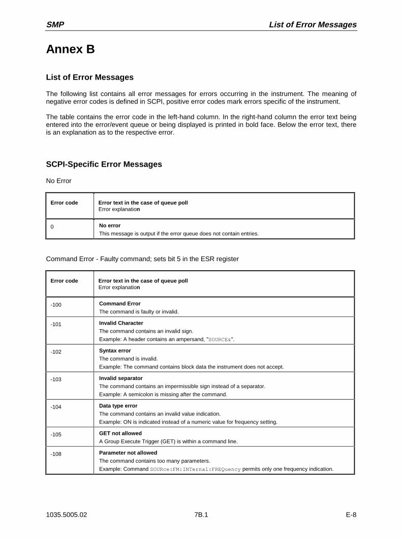
SMP List of Error Messages
1035.5005.02 7B.1 E-8
Annex B
List of Error Messages
The following list contains all error messages for errors occurring in the instrument. The meaning ofnegative error codes is defined in SCPI, positive error codes mark errors specific of the instrument.
The table contains the error code in the left-hand column. In the right-hand column the error text beingentered into the error/event queue or being displayed is printed in bold face. Below the error text, thereis an explanation as to the respective error.
SCPI-Specific Error Messages
No Error
Error code Error text in the case of queue pollError explanation
0 No error
This message is output if the error queue does not contain entries.
Command Error - Faulty command; sets bit 5 in the ESR register
Error code Error text in the case of queue pollError explanation
-100 Command Error
The command is faulty or invalid.
-101 Invalid Character
The command contains an invalid sign.
Example: A header contains an ampersand, "SOURCE&".
-102 Syntax error
The command is invalid.
Example: The command contains block data the instrument does not accept.
-103 Invalid separator
The command contains an impermissible sign instead of a separator.
Example: A semicolon is missing after the command.
-104 Data type error
The command contains an invalid value indication.
Example: ON is indicated instead of a numeric value for frequency setting.
-105 GET not allowed
A Group Execute Trigger (GET) is within a command line.
-108 Parameter not allowed
The command contains too many parameters.
Example: Command SOURce:FM:INTernal:FREQuency permits only one frequency indication.
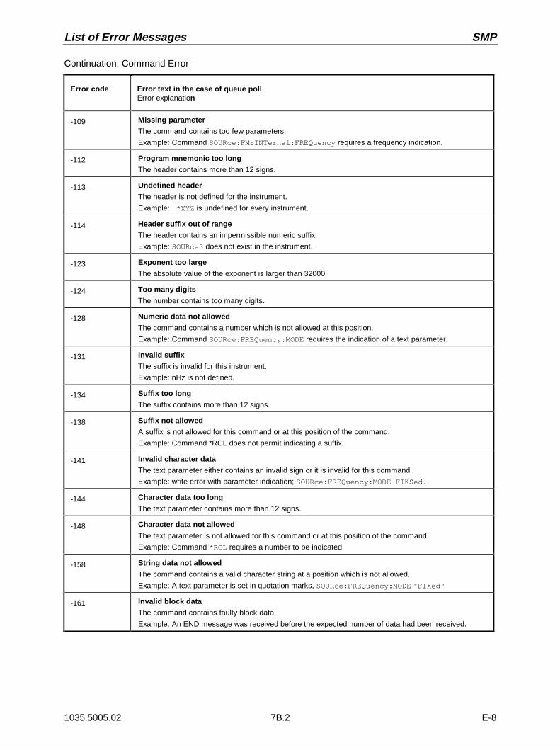
List of Error Messages SMP
1035.5005.02 7B.2 E-8
Continuation: Command Error
Error code Error text in the case of queue pollError explanation
-109 Missing parameter
The command contains too few parameters.
Example: Command SOURce:FM:INTernal:FREQuency requires a frequency indication.
-112 Program mnemonic too long
The header contains more than 12 signs.
-113 Undefined header
The header is not defined for the instrument.
Example: *XYZ is undefined for every instrument.
-114 Header suffix out of range
The header contains an impermissible numeric suffix.
Example: SOURce3 does not exist in the instrument.
-123 Exponent too large
The absolute value of the exponent is larger than 32000.
-124 Too many digits
The number contains too many digits.
-128 Numeric data not allowed
The command contains a number which is not allowed at this position.
Example: Command SOURce:FREQuency:MODE requires the indication of a text parameter.
-131 Invalid suffix
The suffix is invalid for this instrument.
Example: nHz is not defined.
-134 Suffix too long
The suffix contains more than 12 signs.
-138 Suffix not allowed
A suffix is not allowed for this command or at this position of the command.
Example: Command *RCL does not permit indicating a suffix.
-141 Invalid character data
The text parameter either contains an invalid sign or it is invalid for this command
Example: write error with parameter indication; SOURce:FREQuency:MODE FIKSed.
-144 Character data too long
The text parameter contains more than 12 signs.
-148 Character data not allowed
The text parameter is not allowed for this command or at this position of the command.
Example: Command *RCL requires a number to be indicated.
-158 String data not allowed
The command contains a valid character string at a position which is not allowed.
Example: A text parameter is set in quotation marks, SOURce:FREQuency:MODE "FIXed"
-161 Invalid block data
The command contains faulty block data.
Example: An END message was received before the expected number of data had been received.
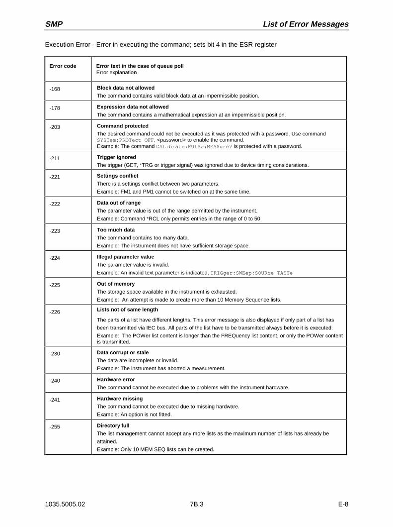
SMP List of Error Messages
1035.5005.02 7B.3 E-8
Execution Error - Error in executing the command; sets bit 4 in the ESR register
Error code Error text in the case of queue pollError explanation
-168 Block data not allowed
The command contains valid block data at an impermissible position.
-178 Expression data not allowed
The command contains a mathematical expression at an impermissible position.
-203 Command protectedThe desired command could not be executed as it was protected with a password. Use commandSYSTem:PROTect OFF, <password> to enable the command.Example: The command CALibrate:PULSe:MEASure? is protected with a password.
-211 Trigger ignoredThe trigger (GET, *TRG or trigger signal) was ignored due to device timing considerations.
-221 Settings conflict
There is a settings conflict between two parameters.
Example: FM1 and PM1 cannot be switched on at the same time.
-222 Data out of range
The parameter value is out of the range permitted by the instrument.
Example: Command *RCL only permits entries in the range of 0 to 50
-223 Too much data
The command contains too many data.
Example: The instrument does not have sufficient storage space.
-224 Illegal parameter value
The parameter value is invalid.
Example: An invalid text parameter is indicated, TRIGger:SWEep:SOURce TASTe
-225 Out of memory
The storage space available in the instrument is exhausted.
Example: An attempt is made to create more than 10 Memory Sequence lists.
-226 Lists not of same length
The parts of a list have different lengths. This error message is also displayed if only part of a list has
been transmitted via IEC bus. All parts of the list have to be transmitted always before it is executed.
Example: The POWer list content is longer than the FREQuency list content, or only the POWer contentis transmitted.
-230 Data corrupt or stale
The data are incomplete or invalid.
Example: The instrument has aborted a measurement.
-240 Hardware error
The command cannot be executed due to problems with the instrument hardware.
-241 Hardware missing
The command cannot be executed due to missing hardware.
Example: An option is not fitted.
-255 Directory full
The list management cannot accept any more lists as the maximum number of lists has already be
attained.
Example: Only 10 MEM SEQ lists can be created.
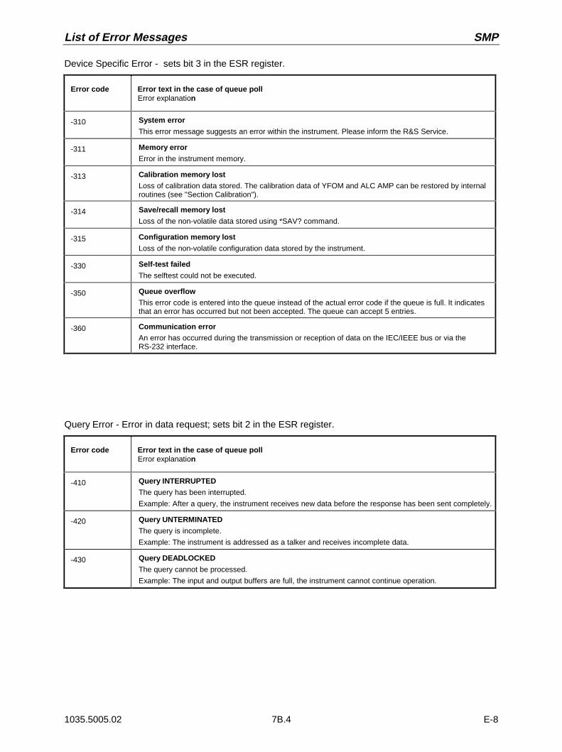
List of Error Messages SMP
1035.5005.02 7B.4 E-8
Device Specific Error - sets bit 3 in the ESR register.
Error code Error text in the case of queue pollError explanation
-310 System error
This error message suggests an error within the instrument. Please inform the R&S Service.
-311 Memory error
Error in the instrument memory.
-313 Calibration memory lostLoss of calibration data stored. The calibration data of YFOM and ALC AMP can be restored by internalroutines (see "Section Calibration").
-314 Save/recall memory lost
Loss of the non-volatile data stored using *SAV? command.
-315 Configuration memory lost
Loss of the non-volatile configuration data stored by the instrument.
-330 Self-test failed
The selftest could not be executed.
-350 Queue overflowThis error code is entered into the queue instead of the actual error code if the queue is full. It indicatesthat an error has occurred but not been accepted. The queue can accept 5 entries.
-360 Communication errorAn error has occurred during the transmission or reception of data on the IEC/IEEE bus or via theRS-232 interface.
Query Error - Error in data request; sets bit 2 in the ESR register.
Error code Error text in the case of queue pollError explanation
-410 Query INTERRUPTED
The query has been interrupted.
Example: After a query, the instrument receives new data before the response has been sent completely.
-420 Query UNTERMINATED
The query is incomplete.
Example: The instrument is addressed as a talker and receives incomplete data.
-430 Query DEADLOCKED
The query cannot be processed.
Example: The input and output buffers are full, the instrument cannot continue operation.
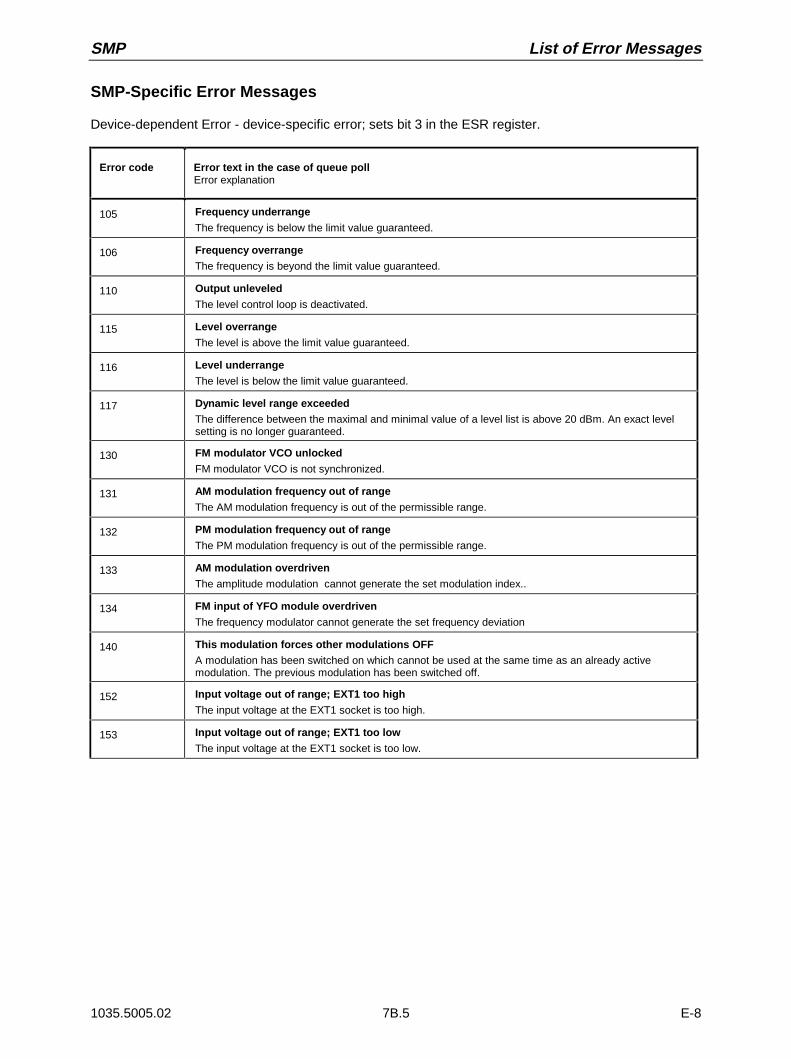
SMP List of Error Messages
1035.5005.02 7B.5 E-8
SMP-Specific Error Messages
Device-dependent Error - device-specific error; sets bit 3 in the ESR register.
Error code Error text in the case of queue pollError explanation
105 Frequency underrange
The frequency is below the limit value guaranteed.
106 Frequency overrange
The frequency is beyond the limit value guaranteed.
110 Output unleveled
The level control loop is deactivated.
115 Level overrange
The level is above the limit value guaranteed.
116 Level underrange
The level is below the limit value guaranteed.
117 Dynamic level range exceededThe difference between the maximal and minimal value of a level list is above 20 dBm. An exact levelsetting is no longer guaranteed.
130 FM modulator VCO unlocked
FM modulator VCO is not synchronized.
131 AM modulation frequency out of range
The AM modulation frequency is out of the permissible range.
132 PM modulation frequency out of range
The PM modulation frequency is out of the permissible range.
133 AM modulation overdriven
The amplitude modulation cannot generate the set modulation index..
134 FM input of YFO module overdriven
The frequency modulator cannot generate the set frequency deviation
140 This modulation forces other modulations OFFA modulation has been switched on which cannot be used at the same time as an already activemodulation. The previous modulation has been switched off.
152 Input voltage out of range; EXT1 too high
The input voltage at the EXT1 socket is too high.
153 Input voltage out of range; EXT1 too low
The input voltage at the EXT1 socket is too low.
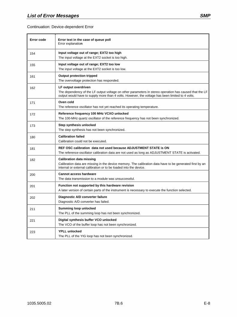
List of Error Messages SMP
1035.5005.02 7B.6 E-8
Continuation: Device-dependent Error
Error code Error text in the case of queue pollError explanation
154 Input voltage out of range; EXT2 too high
The input voltage at the EXT2 socket is too high.
155 Input voltage out of range; EXT2 too low
The input voltage at the EXT2 socket is too low.
161 Output protection tripped
The overvoltage protection has responded.
162 LF output overdrivenThe dependency of the LF output voltage on other parameters in stereo operation has caused that the LFoutput would have to supply more than 4 volts. However, the voltage has been limited to 4 volts.
171 Oven cold
The reference oscillator has not yet reached its operating temperature.
172 Reference frequency 100 MHz VCXO unlocked
The 100-MHz quartz oscillator of the reference frequency has not been synchronized.
173 Step synthesis unlocked
The step synthesis has not been synchronized.
180 Calibration failed
Calibration could not be executed.
181 REF OSC calibration data not used because ADJUSTMENT STATE is ONThe reference-oscillator calibration data are not used as long as ADJUSTMENT STATE is activated.
182 Calibration data missingCalibration data are missing in the device memory. The calibration data have to be generated first by aninternal or external calibration or to be loaded into the device.
200 Cannot access hardware
The data transmission to a module was unsuccessful.
201 Function not supported by this hardware revision
A later version of certain parts of the instrument is necessary to execute the function selected.
202 Diagnostic A/D converter failure
Diagnostic A/D converter has failed.
211 Summing loop unlocked
The PLL of the summing loop has not been synchronized.
221 Digital synthesis buffer VCO unlocked
The VCO of the buffer loop has not been synchronized.
223 YPLL unlocked
The PLL of the YIG loop has not been synchronized.
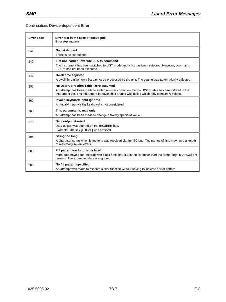
SMP List of Error Messages
1035.5005.02 7B.7 E-8
Continuation: Device-dependent Error
Error code Error text in the case of queue pollError explanation
241 No list definedThere is no list defined..
242 List not learned; execute LEARn commandThe instrument has been switched to LIST mode and a list has been selected. However, commandLEARn has not been executed.
243 Dwell time adjustedA dwell time given on a list cannot be processed by the unit. The setting was automatically adjusted.
251 No User Correction Table; zero assumedAn attempt has been made to switch on user correction, but no UCOR table has been stored in theinstrument yet. The instrument behaves as if a table was called which only contains 0-values.
260 Invalid keyboard input ignoredAn invalid input via the keyboard is not considered.
265 This parameter is read onlyAn attempt has been made to change a fixedly specified value.
270 Data output abortedData output was aborted on the IEC/IEEE-bus.Example: The key [LOCAL] was pressed.
304 String too longA character string which is too long was received via the IEC bus. The names of lists may have a lengthof maximally seven letters.
305 Fill pattern too long; trunctatedMore data have been entered with block function FILL in the list editor than the filling range (RANGE) setpermits. The exceeding data are ignored.
306 No fill pattern specifiedAn attempt was made to execute a filler function without having to indicate a filler pattern.

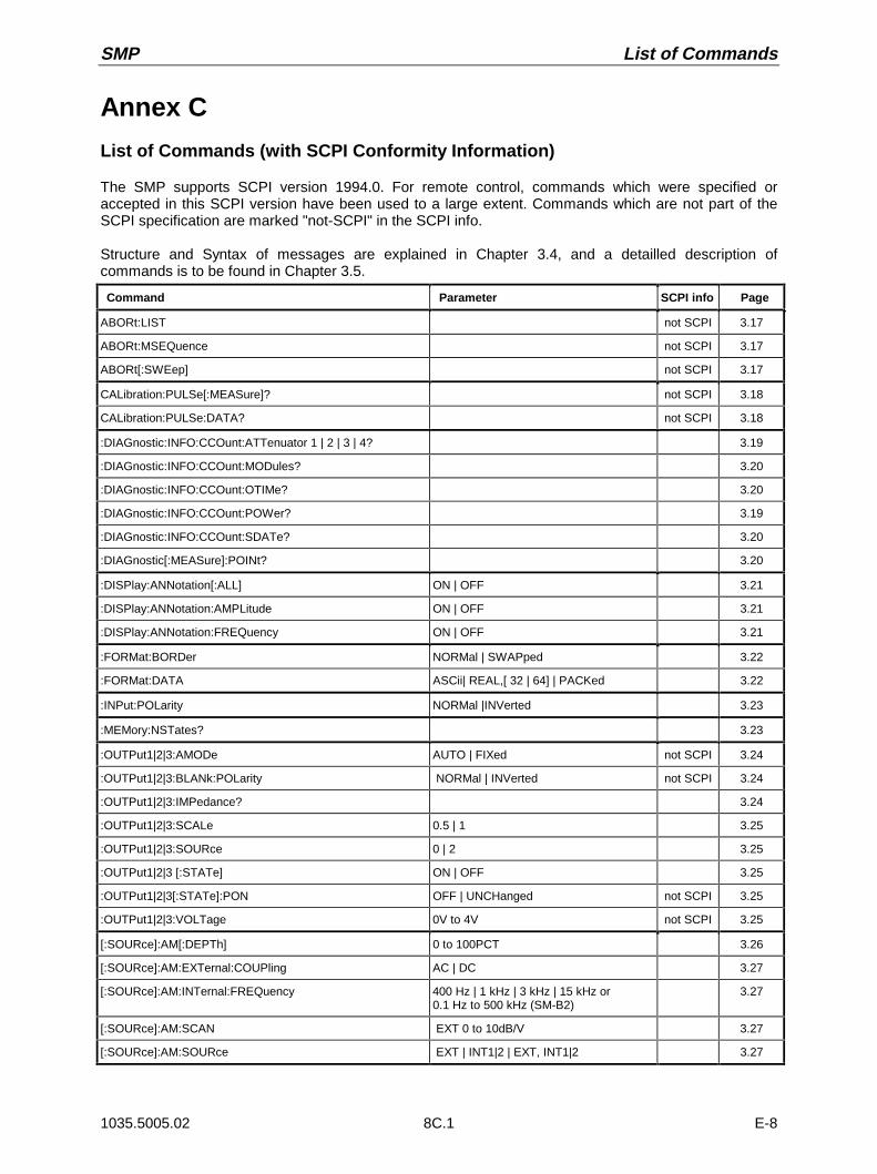
SMP List of Commands
1035.5005.02 8C.1 E-8
Annex C
List of Commands (with SCPI Conformity Information)
The SMP supports SCPI version 1994.0. For remote control, commands which were specified oraccepted in this SCPI version have been used to a large extent. Commands which are not part of theSCPI specification are marked "not-SCPI" in the SCPI info.
Structure and Syntax of messages are explained in Chapter 3.4, and a detailled description ofcommands is to be found in Chapter 3.5.
Command Parameter SCPI info Page
ABORt:LIST not SCPI 3.17
ABORt:MSEQuence not SCPI 3.17
ABORt[:SWEep] not SCPI 3.17
CALibration:PULSe[:MEASure]? not SCPI 3.18
CALibration:PULSe:DATA? not SCPI 3.18
:DIAGnostic:INFO:CCOunt:ATTenuator 1 | 2 | 3 | 4? 3.19
:DIAGnostic:INFO:CCOunt:MODules? 3.20
:DIAGnostic:INFO:CCOunt:OTIMe? 3.20
:DIAGnostic:INFO:CCOunt:POWer? 3.19
:DIAGnostic:INFO:CCOunt:SDATe? 3.20
:DIAGnostic[:MEASure]:POINt? 3.20
:DISPlay:ANNotation[:ALL] ON | OFF 3.21
:DISPlay:ANNotation:AMPLitude ON | OFF 3.21
:DISPlay:ANNotation:FREQuency ON | OFF 3.21
:FORMat:BORDer NORMal | SWAPped 3.22
:FORMat:DATA ASCii| REAL,[ 32 | 64] | PACKed 3.22
:INPut:POLarity NORMal |INVerted 3.23
:MEMory:NSTates? 3.23
:OUTPut1|2|3:AMODe AUTO | FIXed not SCPI 3.24
:OUTPut1|2|3:BLANk:POLarity NORMal | INVerted not SCPI 3.24
:OUTPut1|2|3:IMPedance? 3.24
:OUTPut1|2|3:SCALe 0.5 | 1 3.25
:OUTPut1|2|3:SOURce 0 | 2 3.25
:OUTPut1|2|3 [:STATe] ON | OFF 3.25
:OUTPut1|2|3[:STATe]:PON OFF | UNCHanged not SCPI 3.25
:OUTPut1|2|3:VOLTage 0V to 4V not SCPI 3.25
[:SOURce]:AM[:DEPTh] 0 to 100PCT 3.26
[:SOURce]:AM:EXTernal:COUPling AC | DC 3.27
[:SOURce]:AM:INTernal:FREQuency 400 Hz | 1 kHz | 3 kHz | 15 kHz or0.1 Hz to 500 kHz (SM-B2)
3.27
[:SOURce]:AM:SCAN EXT 0 to 10dB/V 3.27
[:SOURce]:AM:SOURce EXT | INT1|2 | EXT, INT1|2 3.27
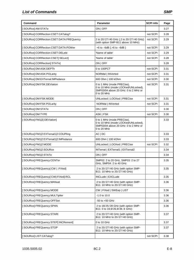
List of Commands SMP
1035.5005.02 8C.2 E-8
Command Parameter SCPI info Page
[:SOURce]:AM:STATe ON | OFF 3.27
[:SOURce]:CORRection:CSET:CATalog? not SCPI 3.28
[:SOURce]:CORRection:CSET:DATA:FREQuency 2 to 20/27/40 GHz ,2 to 20/27/40 GHz(with option SMP-B11 above 10 MHz)
not SCPI 3.29
[:SOURce]:CORRection:CSET:DATA:POWer +6 to –6dB ,+6 to –6dB not SCPI 3.29
[:SOURce]:CORRection:CSET:DELete 'Name of table' not SCPI 3.29
[:SOURce]:CORRection:CSET[:SELect] 'Name of table' not SCPI 3.28
[:SOURce]:CORRection[:STATe] ON | OFF 3.28
[:SOURce]:DM:ASK:DEPTh 0 to 100PCT not-SCPI 3.31
[:SOURce]:DM:ASK:POLarity NORMal | INVerted not-SCPI 3.31
[:SOURce]:DM:EXTernal:IMPedance 600 Ohm | 100 kOhm not SCPI 3.30
[:SOURce]:DM:FSK:DEViation 0 to 1 MHz (mode PRECise),0 to 10 MHz (mode LOCKed/UNLocked),SMP03/04 above 20 GHz: 0 to 2 MHz or0 to 20 MHz
not SCPI 3.31
[:SOURce]:DM:FSK:MODE UNLocked | LOCKed | PRECise not SCPI 3.31
[:SOURce]:DM:FSK:POLarity NORMal | INVerted not SCPI 3.31
[:SOURce]:DM:STATe ON | OFF 3.30
[:SOURce]:DM:TYPE ASK | FSK not SCPI 3.30
[:SOURce]:FM1|2[:DEViation] 0 to 1 MHz (mode PRECise),0 to 10 MHz (mode LOCKed/UNLocked),SMP03/04 above 20 GHz: 0 to 2 MHz or0 to 20 MHz
3.33
[:SOURce]:FM1|2:EXTernal1|2:COUPling AC | DC 3.33
[:SOURce]:FM1|2:EXTernal1|2:IMPedance 600 Ohm | 100 kOhm 3.33
[:SOURce]:FM1|2:MODE UNLocked | LOCKed | PRECise not SCPI 3.32
[:SOURce]:FM1|2:SOURce INTernal | EXTernal1 | EXTernal2 3.34
[:SOURce]:FM1|2:STATe ON | OFF 3.34
[:SOURce]:FREQuency:CENTer SMP02: 2 to 20 GHz, SMP03: 2 to 27GHz, SMP04: 2 to 40 GHz
3.35
[:SOURce]:FREQuency[:CW | :FIXed] 2 to 20/27/40 GHz (with option SMP-B11: 10 MHz to 20/27/40 GHz)
3.35
[:SOURce]:FREQuency[:CW|:FIXed]:RCL INCLude | EXCLude 3.35
[:SOURce]:FREQuency:MANual 2 to 20/27/40 GHz (with option SMP-B11: 10 MHz to 20/27/40 GHz)
3.36
[:SOURce]:FREQuency:MODE CW | FIXed | SWEep | LIST 3.36
[:SOURce]:FREQuency:MULTiplier -1.0 to 10.0 3.36
[:SOURce]:FREQuency:OFFSet -50 to +50 GHz 3.36
[:SOURce]:FREQuency:SPAN 2 to 18/25/28 GHz (with option SMP-B11: 0 to 19,9/26,9/39,9 GHz)
3.36
[:SOURce]:FREQuency:STARt 2 to 20/27/40 GHz (with option SMP-B11: 10 MHz to 20/27/40 GHz)
3.37
[:SOURce]:FREQuency:STEP[:INCRement] 0 to 10 GHz 3.37
[:SOURce]:FREQuency:STOP 2 to 20/27/40 GHz (with option SMP-B11: 10 MHz to 20/27/40 GHz)
3.37
[:SOURce]:LIST:CATalog? not SCPI 3.38

SMP List of Commands
1035.5005.02 8C.3 E-8
Command Parameter SCPI info Page
[:SOURce]:LIST:DELete ‘Name of list’ not SCPI 3.38
[:SOURce]:LIST:DELete:ALL not SCPI 3.38
[:SOURce]:LIST:DWELl 1 ms to 1 s , 1 ms to 1 s 3.39
[:SOURce]:LIST:DWELl:POINts? 3.39
[:SOURce]:LIST:FREE? 3.39
[:SOURce]:LIST:FREQuency 2 to 20/27/40 GHz , 2 to 20/27/40 GHz |block data (option SMP-B11: above 10MHz)
3.39
[:SOURce]:LIST:FREQuency:POINts? 3.39
[:SOURce]:LIST:LEARn not SCPI 3.39
[:SOURce]:LIST:MODE AUTO | STEP not SCPI 3.39
[:SOURce]:LIST:POWer -130 to 27 dBm , -130 to 27 dBm | blockdata (–20 to 27 dBm without option SMP-B15)
3.40
[:SOURce]:LIST:POWer:POINts? 3.40
[:SOURce]:LIST:SELect 'Name of list' not SCPI 3.40
[:SOURce]:MARKer[:FSWeep]1|2|3:AMPLitude ON | OFF 3.41
[:SOURce]:MARKer[:FSWeep]1|2|3:AOFF 3.41
[:SOURce]:MARKer1|2|3[:FSWeep]:FREQuency 2.to 20/27/40 GHz 3.41
[:SOURce]:MARKer1|2|3[:FSWeep][:STATe] ON | OFF 3.42
[:SOURce]:MARKer1|2|3:POLarity NORMal | INVerted not SCPI 3.42
[:SOURce]:MARKer1|2|3:PSWeep:AOFF not SCPI 3.42
[:SOURce]:MARKer1|2|3:PSWeep:POWer -130 dBm to +27 dBm (without optionSMP-B15: –20 dBm to 27 dBm;SMP03/04: below 22 dBm)
not SCPI 3.42
[:SOURce]:MARKer1|2|3:PSWeep[:STATe] ON | OFF not SCPI 3.42
[:SOURce]:PHASe[:ADJust] -360 deg to +360 deg not SCPI 3.43
[:SOURce]:PHASe:REFerence not SCPI 3.43
[:SOURce]:PM1|2[:DEViation] 0 to 10 rad (SMP03/04 above 20 GHz: 0to 20 rad)
3.44
[:SOURce]:PM1|2:EXTernal1|2:COUPling AC | DC 3.44
[:SOURce]:PM1|2:EXTernal1|2:IMPedance 600 Ohm | 100 kOhm 3.45
[:SOURce]:PM1|2:INTernal:FREQuency 400 Hz | 1 kHz | 3 kHz | 15 kHz or0.1 Hz to 500 kHz (option SM-B2)
3.45
[:SOURce]:PM1|2:SOURce INTernal | EXTernal1 | EXTernal2 3.45
[:SOURce]:PM1|2:STATe ON | OFF 3.45
[:SOURce]:POWer:ALC:REFerence 0 to 3 V 3.46
[:SOURce]:POWer:ALC:SEArch ON | OFF | ONCE 3.47
[:SOURce]:POWer:ALC:SOURce INTernal | DIODe | PMETer 3.47
[:SOURce]:POWer:ALC:SOURce:PMETer RS_NRVS | HP436A 3.47
[:SOURce]:POWer:ALC[:STATe] ON | OFF 3.47
[:SOURce]:POWer[:LEVel][:IMMediate][:AMPLitude] –130 dBm to 27 dBm (without optionSMP-B15: –20 dBm to 27 dBm;SMP03/04: below 22 dBm)
3.47
[:SOURce]:POWer[:LEVel][:IMMediate][:AMPLitude]:OFFSet -100 to+100 3.48

List of Commands SMP
1035.5005.02 8C.4 E-8
Command Parameter SCPI info Page
:SOURce]:POWer[:LEVel][:IMMediate][:AMPLitude]:RCL INCLude | EXCLude 3.48
[:SOURce]:POWer:LIMit[:AMPLitude] –130 dBm to 27 dBm (without optionSMP-B15: –20 dBm to 27 dBm;SMP03/04: below 22 dBm)
3.48
[:SOURce]:POWer:MANual –130 dBm to 27 dBm (without optionSMP-B15: –20 dBm to 27 dBm;SMP03/04: below 22 dBm)
3.48
[:SOURce]:POWer:MODE FIXed | SWEep | LIST 3.48
[:SOURce]:POWer:STARt –130 dBm to 27 dBm (without optionSMP-B15: –20 dBm to 27 dBm;SMP03/04: below 22 dBm)
3.49
[:SOURce]:POWer:STOP –130 dBm to 27 dBm (without optionSMP-B15: –20 dBm to 27 dBm;SMP03/04: below 22 dBm)
3.49
[:SOURce]:POWer:STEP[:INCRement] 0.1 to 10 dB 3.49
[:SOURce]:PULM:EXTernal:IMPedance 50 Ohm | 10 kOhm not SCPI 3.50
[:SOURce]:PULM:INTernal:FREQuency 0.01176 Hz to 10 MHz not SCPI 3.50
[:SOURce]:PULM:POLarity NORMal | INVerted not SCPI 3.50
[:SOURce]:PULM:SOURce EXTernal | INTernal not SCPI 3.50
[:SOURce]:PULM:STATe ON | OFF not SCPI 3.50
[:SOURce]:PULSe:DELay 40 ns to 1 s not SCPI 3.51
[:SOURce]:PULSe:DOUBle:DELay 60 ns to 1 s 3.51
[:SOURce]:PULSe:DOUBle[:STATe] ON | OFF 3.51
[:SOURce]:PULSe:PERiod 100 ns to 85 s 3.51
[:SOURce]:PULSe:WIDTh 20 ns to 1s 3.51
[:SOURce]:ROSCillator:EXTernal:FREQuency 1 to 16 MHz 3.52
[:SOURce]:ROSCillator[:INTernal]:ADJust:VALue 0 to 4095 not SCPI 3.52
[:SOURce]:ROSCillator[:INTernal]:ADJust[:STATe] ON | OFF not SCPI 3.52
[:SOURce]:ROSCillator:SOURce INTernal | EXTernal not SCPI 3.52
[:SOURce]:SWEep:BTIMe NORMal | LONG not SCPI 3.53
[:SOURce:]SWEep[:FREQuency]:SPACing LINear | LOGarithmic not SCPI 3.54
[:SOURce]:SWEep:POWer:DWELl 1 ms to 5 s not SCPI 3.55
[:SOURce]:SWEep:POWer:MODE AUTO | MANual | STEP not SCPI 3.55
[:SOURce]:SWEep:POWer:POINts number not-SCPI 3.55
[:SOURce]:SWEep:POWer:SPACing LOGarithmic not-SCPI 3.55
[:SOURce]:SWEep:POWer:STEP:LOGarithmic 0 to 10 dB not SCPI 3.56
[:SOURce]:SWEep[:FREQuency]:DWELl 10 ms to 5 s not SCPI 3.53
[:SOURce]:SWEep[:FREQuency]:MODE AUTO | MANual | STEP not SCPI 3.54
[:SOURce]:SWEep[:FREQuency]:POINts Number not SCPI 3.54
[:SOURce]:SWEep[:FREQuency]:STEP:LOGarithmic 0.01 to 50 PCT not SCPI 3.55
[:SOURce]:SWEep[:FREQuency]:STEP[:LINear 0 to 10 GHz not SCPI 3.54
:SOURce0|2:FREQuency[:CW | :FIXed] 400 Hz | 1 kHz | 3 kHz | 15 kHz or 0.1 Hz to 500 kHz (Option SM-B2)
3.58
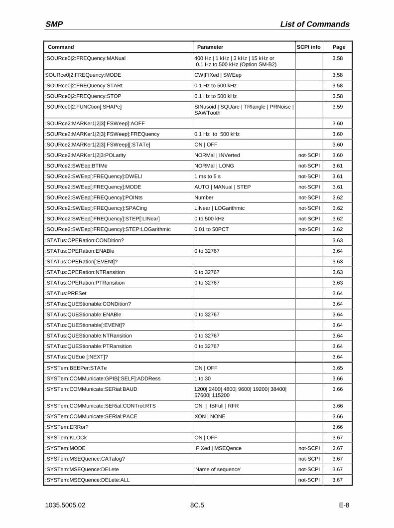
SMP List of Commands
1035.5005.02 8C.5 E-8
Command Parameter SCPI info Page
:SOURce0|2:FREQuency:MANual 400 Hz | 1 kHz | 3 kHz | 15 kHz or 0.1 Hz to 500 kHz (Option SM-B2)
3.58
SOURce0|2:FREQuency:MODE CW|FIXed | SWEep 3.58
:SOURce0|2:FREQuency:STARt 0.1 Hz to 500 kHz 3.58
:SOURce0|2:FREQuency:STOP 0.1 Hz to 500 kHz 3.58
:SOURce0|2:FUNCtion[:SHAPe] SINusoid | SQUare | TRIangle | PRNoise |SAWTooth
3.59
:SOURce2:MARKer1|2|3[:FSWeep]:AOFF 3.60
:SOURce2:MARKer1|2|3[:FSWeep]:FREQuency 0.1 Hz to 500 kHz 3.60
:SOURce2:MARKer1|2|3[:FSWeep][:STATe] ON | OFF 3.60
:SOURce2:MARKer1|2|3:POLarity NORMal | INVerted not-SCPI 3.60
:SOURce2:SWEep:BTIMe NORMal | LONG not-SCPI 3.61
:SOURce2:SWEep[:FREQuency]:DWELl 1 ms to 5 s not-SCPI 3.61
:SOURce2:SWEep[:FREQuency]:MODE AUTO | MANual | STEP not-SCPI 3.61
:SOURce2:SWEep[:FREQuency]:POINts Number not-SCPI 3.62
:SOURce2:SWEep[:FREQuency]:SPACing LINear | LOGarithmic not-SCPI 3.62
:SOURce2:SWEep[:FREQuency]:STEP[:LINear] 0 to 500 kHz not-SCPI 3.62
:SOURce2:SWEep[:FREQuency]:STEP:LOGarithmic 0.01 to 50PCT not-SCPI 3.62
:STATus:OPERation:CONDition? 3.63
:STATus:OPERation:ENABle 0 to 32767 3.64
:STATus:OPERation[:EVENt]? 3.63
:STATus:OPERation:NTRansition 0 to 32767 3.63
:STATus:OPERation:PTRansition 0 to 32767 3.63
:STATus:PRESet 3.64
:STATus:QUEStionable:CONDition? 3.64
:STATus:QUEStionable:ENABle 0 to 32767 3.64
:STATus:QUEStionable[:EVENt]? 3.64
:STATus:QUEStionable:NTRansition 0 to 32767 3.64
:STATus:QUEStionable:PTRansition 0 to 32767 3.64
:STATus:QUEue [:NEXT]? 3.64
:SYSTem:BEEPer:STATe ON | OFF 3.65
:SYSTem:COMMunicate:GPIB[:SELF]:ADDRess 1 to 30 3.66
:SYSTem:COMMunicate:SERial:BAUD 1200| 2400| 4800| 9600| 19200| 38400|57600| 115200
3.66
:SYSTem:COMMunicate:SERial:CONTrol:RTS ON | IBFull | RFR 3.66
:SYSTem:COMMunicate:SERial:PACE XON | NONE 3.66
:SYSTem:ERRor? 3.66
:SYSTem:KLOCk ON | OFF 3.67
:SYSTem:MODE FIXed | MSEQence not-SCPI 3.67
:SYSTem:MSEQuence:CATalog? not-SCPI 3.67
:SYSTem:MSEQuence:DELete ’Name of sequence’ not-SCPI 3.67
:SYSTem:MSEQuence:DELete:ALL not-SCPI 3.67
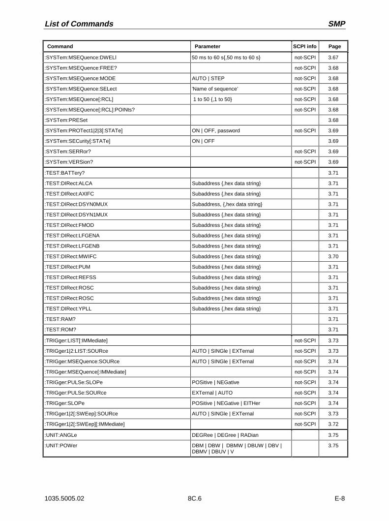
List of Commands SMP
1035.5005.02 8C.6 E-8
Command Parameter SCPI info Page
:SYSTem:MSEQuence:DWELl 50 ms to 60 s,50 ms to 60 s not-SCPI 3.67
:SYSTem:MSEQuence:FREE? not-SCPI 3.68
:SYSTem:MSEQuence:MODE AUTO | STEP not-SCPI 3.68
:SYSTem:MSEQuence:SELect ’Name of sequence’ not-SCPI 3.68
:SYSTem:MSEQuence[:RCL] 1 to 50 ,1 to 50 not-SCPI 3.68
:SYSTem:MSEQuence[:RCL]:POINts? not-SCPI 3.68
:SYSTem:PRESet 3.68
:SYSTem:PROTect1|2|3[:STATe] ON | OFF, password not-SCPI 3.69
:SYSTem:SECurity[:STATe] ON | OFF 3.69
:SYSTem:SERRor? not-SCPI 3.69
:SYSTem:VERSion? not-SCPI 3.69
:TEST:BATTery? 3.71
:TEST:DIRect:ALCA Subaddress ,hex data string 3.71
:TEST:DIRect:AXIFC Subaddress ,hex data string 3.71
:TEST:DIRect:DSYN0MUX Subaddress, ,hex data string 3.71
:TEST:DIRect:DSYN1MUX Subaddress ,hex data string 3.71
:TEST:DIRect:FMOD Subaddress ,hex data string 3.71
:TEST:DIRect:LFGENA Subaddress ,hex data string 3.71
:TEST:DIRect:LFGENB Subaddress ,hex data string 3.71
:TEST:DIRect:MWIFC Subaddress ,hex data string 3.70
:TEST:DIRect:PUM Subaddress ,hex data string 3.71
:TEST:DIRect:REFSS Subaddress ,hex data string 3.71
:TEST:DIRect:ROSC Subaddress ,hex data string 3.71
:TEST:DIRect:ROSC Subaddress ,hex data string 3.71
:TEST:DIRect:YPLL Subaddress ,hex data string 3.71
:TEST:RAM? 3.71
:TEST:ROM? 3.71
:TRIGger:LIST[:IMMediate] not-SCPI 3.73
:TRIGger1|2:LIST:SOURce AUTO | SINGle | EXTernal not-SCPI 3.73
:TRIGger:MSEQuence:SOURce AUTO | SINGle | EXTernal not-SCPI 3.74
:TRIGger:MSEQuence[:IMMediate] not-SCPI 3.74
:TRIGger:PULSe:SLOPe POSitive | NEGative not-SCPI 3.74
:TRIGger:PULSe:SOURce EXTernal | AUTO not-SCPI 3.74
:TRIGger:SLOPe POSitive | NEGative | EITHer not-SCPI 3.74
:TRIGger1|2[:SWEep]:SOURce AUTO | SINGle | EXTernal not-SCPI 3.73
:TRIGger1|2[:SWEep][:IMMediate] not-SCPI 3.72
:UNIT:ANGLe DEGRee | DEGree | RADian 3.75
:UNIT:POWer DBM | DBW | DBMW | DBUW | DBV |DBMV | DBUV | V
3.75

SMP Programming Examples
1035.5005.02 9D.1 E-8
Annex D
Programming Examples
The examples explain the programming of the instrument and can serve as a basis to solve morecomplex programming tasks.
QuickBASIC has been used as programming language. However, the programs can be translated intoother languages.
1. Including IEC-Bus Library for QuickBasic
REM ----------- Include IEC-bus library for quickbasic ----------------’$INCLUDE: ’c:\qbasic\qbdecl4.bas
2. Initialization and Default Status
The IEC bus as well as the settings of the instrument are brought into a defined default status at thebeginning of every program. Subroutines "InitController" and "InitDevice" are used to thiseffect.
2.1. Initiate Controller
REM ------------ Initiate Instrument -----------REM InitControlleriecaddress% = 28 ’IEC-bus address of the instrumentCALL IBFIND("DEV1", generator%) ’Open port to the instrumentCALL IBPAD(generator%, iecaddress%) ’Inform controller on instrument addressCALL IBTMO(generator%, 11) ’Response time to 1 secREM ************************************************************************
2.2. Initiate Instrument
The IEC-bus status registers and instrument settings of the SMP are brought into the default status.
REM ------------ Initiate Instrument --------------REM InitDeviceCALL IBWRT(generator%, "*CLS") ’Reset status registerCALL IBWRT(generator%, "*RST") ’Reset instrumentCALL IBWRT(generator%, "OUTPUT ON") ’Switch on RF outputREM*************************************************************************
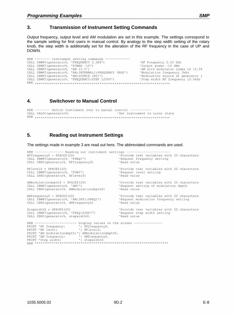
Programming Examples SMP
1035.5005.02 9D.2 E-8
3. Transmission of Instrument Setting Commands
Output frequency, output level and AM modulation are set in this example. The settings correspond tothe sample setting for first users in manual control. By analogy to the step width setting of the rotaryknob, the step width is additionally set for the alteration of the RF frequency in the case of UP andDOWN.
REM -------- Instrument setting commands -------------CALL IBWRT(generator%, "FREQUENCY 2.5E9") ’RF Frequency 2.50 GHzCALL IBWRT(generator%, "POWER -10") ’Output power -10 dBmCALL IBWRT(generator%, "AM 15.5") ’AM with modulaton index of 15.5%CALL IBWRT(generator%, "AM:INTERNAL1:FREQUENCY 3KHZ") ’Modulation frequency 3kHzCALL IBWRT(generator%, "AM:SOURCE INT1") ’Modulation source LF generator 1CALL IBWRT(generator%, "FREQUENCY:STEP 12500") ’Step width RF frequency 12.5kHzREM ***********************************************************************
4. Switchover to Manual Control
REM -------- Switch instrument over to manual control -----------CALL IBLOC(generator%) ’Set instrument to Local stateREM ***********************************************************************
5. Reading out Instrument Settings
The settings made in example 3 are read out here. The abbreviated commands are used.
REM --------------- Reading out instrument settings -----------------------RFfrequency$ = SPACE$(20) ’Provide text variables with 20 charactersCALL IBWRT(generator%, "FREQ?") ’Request frequency settingCALL IBRD(generator%, RFfrequency$) ’Read value
RFlevel$ = SPACE$(20) ’Provide text variables with 20 charactersCALL IBWRT(generator%, "POW?") ’Request level settingCALL IBRD(generator%, RFlevel$) ’Read value
AMmodulationdepth$ = SPACE$(20) ’Provide text variables with 20 charactersCALL IBWRT(generator%, "AM?") ’Request setting of modulation depthCALL IBRD(generator%, AMmodulationdepth$) ’Read value
AMfrequency$ = SPACE$(20) ’Provide text variables with 20 charactersCALL IBWRT(generator%, "AM:INT1:FREQ?") ’Request modulation frequency settingCALL IBRD(generator%, AMfrequency$) ’Read value
Stepwidth$ = SPACE$(20) ’Provide text variables with 20 charactersCALL IBWRT(generator%, "FREQ:STEP?") ’Request step width settingCALL IBRD(generator%, stepwidth$) ’Read value
REM ---------------------- Display values on the screen ---------------PRINT "RF frequency: "; RFfrequency$,PRINT "RF level: "; RFlevel$,PRINT "AM modulationdepth:"; AMmodulationdepth$,PRINT "AM frequency: "; AMfrequency$,PRINT "Step width: "; stepwidth$REM **********************************************************************

SMP Programming Examples
1035.5005.02 9D.3 E-8
6. List Management
REM ----------------------------- Example of list management -------------------------CALL IBWRT(generator%, "LIST:SELECT "+CHR$(34)+"LIST1"+CHR$(34))’Select list "LIST1", is generated if necessaryCALL IBWRT(generator%, "LIST:POWER -30,-15,-10,-5,0,0.1)’Fill power list with valuesCALL IBWRT(generator%, "LIST:FREQ 1.4GHz,1.3GHz,1.2GHz,1.1GHz,1.2GHz,1.3GHz"’Fill frequency list with valuesCALL IBWRT(generator%, "LIST:DWELL 0.2") ’200ms per itemCALL IBWRT(generator%, "TRIGGER21:LIST:SOURCE AUTO") ’Permanently repeat list automaticallyCALL IBWRT(generator%, "POWER:MODE LIST") ’Switch over instrument to list modeREM **********************************************************************
7. Command synchronization
The possibilities for synchronization implemented in the following example are described in Section"Command Order and Command Synchronization".
REM ----------------------- Examples of command synchronization ----------------------REM Command ROSCILLATOR:SOURCE INT has a relatively long execution timeREM (over 300ms). It is to be ensured that the next command is only executedREM when the reference oscillator has settled.
REM First possibility: Use of *WAI ---------------------------------------------CALL IBWRT(generator%, "ROSCILLATOR:SOURCE INT; *WAI; :FREQUENCY 100MHZ")
REM Second possibility: Use of *OPC? -------------------------------------------OpcOk$ = SPACE$(2) ’Space for *OPC? - Provide responseCALL IBWRT(generator%, "ROSCILLATOR:SOURCE INT; *OPC?")REM ----------- here the controller can service other instruments ----------------------CALL IBRD(generator%, OpcOk$) ’Wait for "1" from *OPC?
REM Third possibility: Use of *OPCREM In order to be able to use the service request function in conjugation with a NationalREM Instruments GPIB driver, the setting "Disable Auto Serial Poll" must be changed to "yes"REM by means of IBCONF.CALL IBWRT(generator%, "*SRE 32") ’Permit service request for ESRCALL IBWRT(generator%, "*ESE 1") ’Set event-enable bit for operation-complete bitON PEN GOSUB OpcReady ’Initialization of the service request routinePEN ONCALL IBWRT(generator%, "ROSCILLATOR:SOURCE INT; *OPC")REM Continue main program hereSTOP ’End of program
OpcReady:REM As soon as the reference oscillator has settled, this subroutine is activatedREM Program suitable reaction to the OPC service request.ON PEN GOSUB OpcReady ’Enable SRQ routine againRETURNREM **********************************************************************
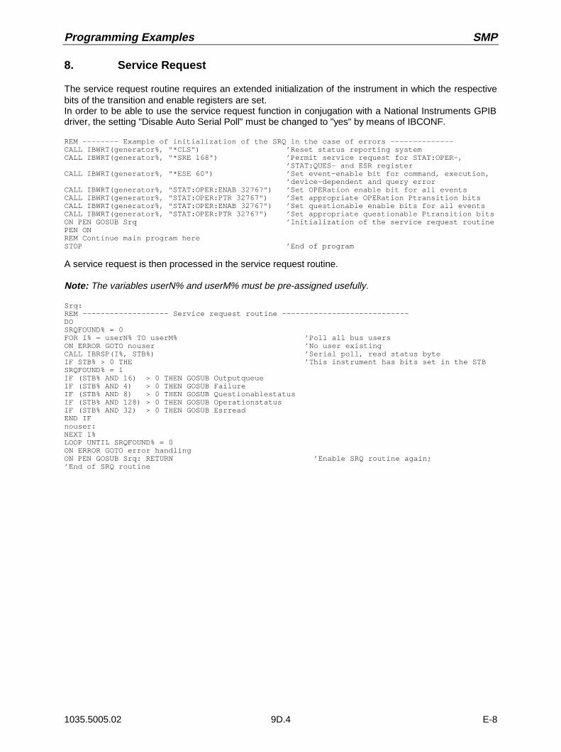
Programming Examples SMP
1035.5005.02 9D.4 E-8
8. Service Request
The service request routine requires an extended initialization of the instrument in which the respectivebits of the transition and enable registers are set.In order to be able to use the service request function in conjugation with a National Instruments GPIBdriver, the setting "Disable Auto Serial Poll" must be changed to "yes" by means of IBCONF.
REM -------- Example of initialization of the SRQ in the case of errors --------------CALL IBWRT(generator%, "*CLS") ’Reset status reporting systemCALL IBWRT(generator%, "*SRE 168") ’Permit service request for STAT:OPER-, ’STAT:QUES- and ESR registerCALL IBWRT(generator%, "*ESE 60") ’Set event-enable bit for command, execution, ’device-dependent and query errorCALL IBWRT(generator%, "STAT:OPER:ENAB 32767") ’Set OPERation enable bit for all eventsCALL IBWRT(generator%, "STAT:OPER:PTR 32767") ’Set appropriate OPERation Ptransition bitsCALL IBWRT(generator%, "STAT:OPER:ENAB 32767") ’Set questionable enable bits for all eventsCALL IBWRT(generator%, "STAT:OPER:PTR 32767") ’Set appropriate questionable Ptransition bitsON PEN GOSUB Srq ’Initialization of the service request routinePEN ONREM Continue main program hereSTOP ’End of program
A service request is then processed in the service request routine.
Note: The variables userN% and userM% must be pre-assigned usefully.
Srq:REM ------------------- Service request routine ----------------------------DOSRQFOUND% = 0FOR I% = userN% TO userM% ’Poll all bus usersON ERROR GOTO nouser ’No user existingCALL IBRSP(I%, STB%) ’Serial poll, read status byteIF STB% > 0 THE ’This instrument has bits set in the STBSRQFOUND% = 1IF (STB% AND 16) > 0 THEN GOSUB OutputqueueIF (STB% AND 4) > 0 THEN GOSUB FailureIF (STB% AND 8) > 0 THEN GOSUB QuestionablestatusIF (STB% AND 128) > 0 THEN GOSUB OperationstatusIF (STB% AND 32) > 0 THEN GOSUB EsrreadEND IFnouser:NEXT I%LOOP UNTIL SRQFOUND% = 0ON ERROR GOTO error handlingON PEN GOSUB Srq: RETURN ’Enable SRQ routine again;’End of SRQ routine
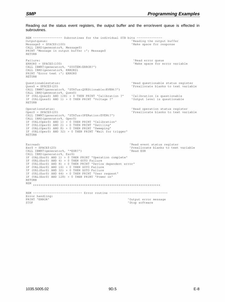
SMP Programming Examples
1035.5005.02 9D.5 E-8
Reading out the status event registers, the output buffer and the error/event queue is effected insubroutines.
REM ---------------- Subroutines for the individual STB bits --------------Outputqueue: ’Reading the output bufferMessage$ = SPACE$(100) ’Make space for responseCALL IBRD(generator%, Message$)PRINT "Message in output buffer :"; Message$RETURN
Failure: ’Read error queueERROR$ = SPACE$(100) ’Make space for error variableCALL IBWRT(generator%, "SYSTEM:ERROR?")CALL IBRD(generator%, ERROR$)PRINT "Error text :"; ERROR$RETURN
Questionablestatus: ’Read questionable status registerQues$ = SPACE$(20) ’Preallocate blanks to text variableCALL IBWRT(generator%, "STATus:QUEStionable:EVENt?")CALL IBRD(generator%, Ques$)IF (VAL(Ques$) AND 128) > 0 THEN PRINT "Calibration ?" ’Calibration is questionableIF (VAL(Ques$) AND 1) > 0 THEN PRINT "Voltage ?" ’Output level is questionableRETURN
Operationstatus: ’Read operation status registerOper$ = SPACE$(20) ’Preallocate blanks to text variableCALL IBWRT(generator%, "STATus:OPERation:EVENt?")CALL IBRD(generator%, Oper$)IF (VAL(Oper$) AND 1) > 0 THEN PRINT "Calibration"IF (VAL(Oper$) AND 2) > 0 THEN PRINT "Settling"IF (VAL(Oper$) AND 8) > 0 THEN PRINT "Sweeping"IF (VAL(Oper$) AND 32) > 0 THEN PRINT "Wait for trigger"RETURN
Esrread: ’Read event status registerEsr$ = SPACE$(20) ’Preallocate blanks to text variableCALL IBWRT(generator%, "*ESR?") ’Read ESRCALL IBRD(generator%, Esr$)IF (VAL(Esr$) AND 1) > 0 THEN PRINT "Operation complete"IF (VAL(Esr$) AND 4) > 0 THEN GOTO FailureIF (VAL(Esr$) AND 8) > 0 THEN PRINT "Device dependent error"IF (VAL(Esr$) AND 16) > 0 THEN GOTO FailureIF (VAL(Esr$) AND 32) > 0 THEN GOTO FailureIF (VAL(Esr$) AND 64) > 0 THEN PRINT "User request"IF (VAL(Esr$) AND 128) > 0 THEN PRINT "Power on"RETURNREM
**********************************************************************
REM --------------------------- Error routine --------------------------------Error handling:PRINT "ERROR" ’Output error messageSTOP ’Stop software

Programming Examples SMP
1035.5005.02 9D.6 E-8
9. Operating the Generator in the IEC-Bus Controller Mode
--------------------- Initializations ----------------------------------
’ ATTENTION: Specify your own addresses here!!
pcadr% = 0 ’ enter IEC-bus-address of the PC !gen_adr% = 28 ’ enter IEC-bus-address of the SMP
CALL IBFIND("gpib0", pc) ’ set IEC-Bus-address of the PCCALL IBPAD(pc, pcadr%)
CALL IBFIND("dev1", generator) ’ SMP can be controlled under Device1CALL IBPAD(generator, gen_adr%)
------------------------ Main program ------------------------------------
Command$ = "sour:corr:coll" ’ SCPI-command for automatic UCOR
a$ = "*pcb " + STR$(pcadr%) ’ tells the SMP to return controlCALL IBWRT(generator, a$) ’ to the address pcadr% afterwards
CALL IBWRT(generator, Command$) ’ Readout of the command itself
CALL IBPCT(generator) ’ Control is given to the SMP
’ --- Waiting for return of control
MASK% = &H4020 ’ CIC or TimeoutCALL IBWAIT(brd%, MASK%)
IF IBSTA% AND &H4000 THEN PRINT "Timeout; control not received" ENDELSE PRINT "Control taken back"END IF
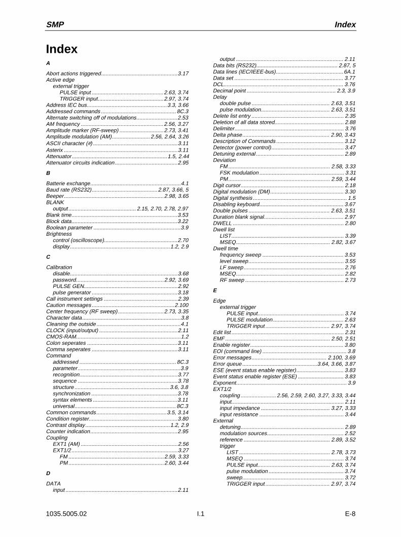
SMP Index
1035.5005.02 I.1 E-8
Index
A
Abort actions triggered..................................................3.17Active edge
external triggerPULSE input ...............................................2.63, 3.74TRIGGER input...........................................2.97, 3.74
Address IEC bus....................................................3.3, 3.66Addressed commands ................................................. 8C.3Alternate switching off of modulations...........................2.53AM frequency ......................................................2.56, 3.27Amplitude marker (RF-sweep) .............................2.73, 3.41Amplitude modulation (AM)......................... 2.56, 2.64, 3.26ASCII character (#) .......................................................3.11Asterix ..........................................................................3.11Attenuator..............................................................1.5, 2.44Attenuator circuits indication.........................................2.95
B
Batterie exchange...........................................................4.1Baud rate (RS232)...........................................2.87, 3.66, 5Beeper.................................................................2.98, 3.65BLANK
output ............................................ 2.15, 2.70, 2.78, 2.97Blank time.....................................................................3.53Block data.....................................................................3.22Boolean parameter .........................................................3.9Brightness
control (oscilloscope)................................................2.70display.................................................................1.2, 2.9
C
Calibrationdisable......................................................................3.68password.........................................................2.92, 3.69PULSE GEN.............................................................2.92pulse generator ........................................................3.18
Call instrument settings ................................................2.39Caution messages ......................................................2.100Center frequency (RF sweep)..............................2.73, 3.35Character data................................................................3.8Cleaning the outside .......................................................4.1CLOCK (input/output) ...................................................2.11CMOS-RAM....................................................................1.2Colon seperates ...........................................................3.11Comma seperates ........................................................3.11Command
addressed ............................................................... 8C.3parameter...................................................................3.9recognition................................................................3.77sequence .................................................................3.78structure ..............................................................3.6, 3.8synchronization ........................................................3.78syntax elements .......................................................3.11universal.................................................................. 8C.3
Common commands..............................................3.5, 3.14Condition register..........................................................3.80Contrast display.......................................................1.2, 2.9Counter indication.........................................................2.95Coupling
EXT1 (AM) ...............................................................2.56EXT1/2 .....................................................................3.27
FM ..............................................................2.59, 3.33PM..............................................................2.60, 3.44
D
DATAinput .........................................................................2.11
output ...................................................................... 2.11Data bits (RS232)..................................................... 2.87, 5Data lines (IEC/IEEE-bus)............................................6A.1Data set ....................................................................... 3.77DCL.............................................................................. 3.76Decimal point .......................................................... 2.3, 3.9Delay
double pulse ................................................... 2.63, 3.51pulse modulation............................................. 2.63, 3.51
Delete list entry ............................................................ 2.35Deletion of all data stored............................................. 2.88Delimiter....................................................................... 3.76Delta phase......................................................... 2.90, 3.43Description of Commands ............................................ 3.12Detector (power control)............................................... 3.47Detuning external ......................................................... 2.89Deviation
FM .................................................................. 2.58, 3.33FSK modulation ....................................................... 3.31PM.................................................................. 2.59, 3.44
Digit cursor................................................................... 2.18Digital modulation (DM)................................................ 3.30Digital synthesis ............................................................. 1.5Disabling keyboard....................................................... 3.67Double pulses ..................................................... 2.63, 3.51Duration blank signal.................................................... 2.97DWELL ........................................................................ 2.80Dwell list
LIST......................................................................... 3.39MSEQ............................................................. 2.82, 3.67
Dwell timefrequency sweep ..................................................... 3.53level sweep.............................................................. 3.55LF sweep................................................................. 2.76MSEQ...................................................................... 2.82RF sweep ................................................................ 2.73
E
Edgeexternal trigger
PULSE input........................................................ 3.74PULSE modulation .............................................. 2.63TRIGGER input .......................................... 2.97, 3.74
Edit list ......................................................................... 2.31EMF .................................................................... 2.50, 2.51Enable register............................................................. 3.80EOI (command line) ....................................................... 3.8Error messages................................................. 2.100, 3.69Error queue .................................................3.64, 3.66, 3.87ESE (event status enable register)............................... 3.83Event status enable register (ESE) .............................. 3.83Exponent........................................................................ 3.9EXT1/2
coupling ....................... 2.56, 2.59, 2.60, 3.27, 3.33, 3.44input......................................................................... 2.11input impedance ............................................. 3.27, 3.33input resistance ....................................................... 3.44
Externaldetuning................................................................... 2.89modulation sources.................................................. 2.52reference ........................................................ 2.89, 3.52trigger
LIST ........................................................... 2.78, 3.73MSEQ ................................................................. 3.74PULSE input............................................... 2.63, 3.74pulse modulation ................................................. 3.74sweep.................................................................. 3.72TRIGGER input .......................................... 2.97, 3.74

Index SMP
1035.5005.02 I.2 E-8
F
Fitting option...................................................................1.4FM
coupling...........................................................2.59, 3.33deviation..........................................................2.58, 3.33frequency ........................................................2.58, 3.34modulator ..........................................................1.7, 2.58
Format data (IEC bus) ..................................................3.22Frequency
accuracy.....................................................................1.2AM ..................................................................2.56, 3.27FM...................................................................2.58, 3.34indication.........................................................2.18, 2.88LF generator....................................................2.67, 3.58LF sweep ............................. 2.75, 2.76, 3.58, 3.60, 3.61list ...................................................................2.77, 3.39modulation (FM) ..............................................2.57, 3.32multiplier...................................................................3.36offset ...............................................................2.41, 3.36PM ..................................................................2.59, 3.45pulse modulation ......................................................3.49RF output signal ..............................................2.41, 3.35RF sweep............................................... 2.73, 3.37, 3.41
Front unit ........................................................................1.5FSK modulation ............................................................3.31Functional test ................................................................4.4
G
GET (Group Execute Trigger) .......................................3.77
H
Handshake RS232...........................................2.87, 3.66, 6Header (commands) .......................................................3.6Header field (display)....................................................2.18
I
IEC/IEEE-bus interface................................................ 6A.1IEC-bus
address ....................................................2.86, 3.3, 3.66interface ...................................................................2.17language ..................................................................2.89
Incompatible modulations .............................................2.53Indication
attenuator circuits.....................................................2.95counter .....................................................................2.95during Remote Control ...............................................3.4error messages ........................................................3.64modules ..........................................................2.93, 3.20operating-hours ........................................................2.95operating-time counter..............................................3.20serial number ...........................................................2.95software version ..............................................2.95, 3.20suppressed...............................................................2.88
Initial Status....................................................................1.2Input
buffer........................................................................3.76CLOCK.....................................................................2.11correction .................................................................2.23DATA .......................................................................2.11EXT1/2 .....................................................................2.11impedance EXT1 (AM) .............................................3.27impedance EXT1/2 FM.............................................3.33modulations..............................................................2.52PULSE .....................................................................3.74resistance.................................................................2.11resistance EXT1/2 PM..............................................3.44STOP .......................................................................2.15TRIGGER...................................... 2.78, 2.83, 2.97, 3.74TUNE .......................................................................2.89
Insert list entry ..............................................................2.34
Instrument settingscall ........................................................................... 2.39store ........................................................................ 2.39
Instrument states (reset) .............................................. 3.68Interface
functions (IEC/IEEE-bus).........................................6A.2functions (RS-232-C) ...............................................6A.5messages (IEC/IEEE-bus) .......................................6A.3
Interface Messages........................................................ 3.4Intermodulation ratio .................................................... 2.46Interrupt ....................................................................... 3.82Interrupt-free level setting............................................. 2.45IST flag ........................................................................ 3.15
K
Key-/ 2.3[ASSIGN]................................................................. 2.21[ERROR] ............................................................... 2.100[FREQ] .................................................................... 2.41[G/n ......................................................................... 2.5[HELP] ..................................................................... 2.99[LEVEL] ................................................................... 2.43[LOCAL]..................................................................... 3.3[M/ ........................................................................ 2.5[MENU1/2] ............................................................... 2.21[MOD ON/OFF]............................................... 2.54, 2.96[PRESET] .................................................................. 1.3[RCL] ....................................................................... 2.39[RETURN]................................................................ 2.19[RF ON / OFF] ................................................ 2.22, 2.51[SAVE]..................................................................... 2.39[SELECT] ................................................................ 2.19[STATUS] ................................................................ 2.99ASSIGN..................................................................... 2.9ERROR* .................................................................... 2.7FREQ ........................................................................ 2.3HELP......................................................................... 2.7k/m ............................................................................ 2.5LEVEL ....................................................................... 2.3LOCAL....................................................................... 2.7MENU 1/2.................................................................. 2.9MOD ON/OFF............................................................ 2.7PRESET.................................................................... 2.7RCL ........................................................................... 2.3RETURN.................................................................... 2.5RF ON/OFF ............................................................... 2.7SAVE......................................................................... 2.3SELECT .................................................................... 2.5STATUS .................................................................... 2.7X1/Enter .................................................................... 2.5
Key words (commands).................................................. 3.6Keyboard disabling....................................................... 3.67
L
LEARN......................................................................... 2.80LEARN (LIST mode) ........................................... 2.77, 3.39Level
control............................................................. 2.46, 3.46correction (list UCOR)..................................... 2.48, 3.28indication ........................................................ 2.18, 2.88limit .......................................................................... 3.48limitation .................................................................. 2.44list................................................................... 2.77, 3.40marker ..................................................................... 3.42offset .............................................................. 2.43, 3.47RF output................................................................. 3.47sweep...................................................................... 2.74unit .........................................................2.22, 2.43, 3.75
Dwell time .................................................................... 2.74Starting level ................................................................ 2.74
SMP Index
1035.5005.02 I.3 E-8
Stop level......................................................................2.74Sweep ..........................................................................2.74LF
generator..................................................1.6, 2.66, 3.57frequency....................................................2.67, 3.58signal shape.........................................................2.67waveform ....................................................2.58, 3.59
output ..............................................................2.11, 2.66sweep.......................................................................3.58
Listdelete ..............................................................2.30, 2.35dwell (LIST)..............................................................3.39dwell (MSEQ)..................................................2.82, 3.67edit ...........................................................................2.31Error Messages....................................................... 7B.1fill 2.32frequency ........................................................2.77, 3.39generate...................................................................2.29insert ........................................................................2.34instrument states (MSEQ) ........................................3.68level .........................................................................3.40level (LIST)...............................................................2.77level correction (UCOR) ..................................2.48, 3.28open.........................................................................2.29select .......................................................................2.29store.........................................................................2.31
LISTfunction LEARN...............................................2.77, 3.39inputs/outputs...........................................................2.78manual processing of the list ....................................2.78mode ............................................. 2.77, 3.39, 3.48, 3.73operating modes..............................................2.77, 3.38
Long form (commands)...................................................3.7Lower-case (commands) ................................................3.7
M
Maintenance...................................................................4.1Mantissa.........................................................................3.9MARKER
LF sweep ........................................................2.76, 3.60output ................................... 2.15, 2.78, 2.97, 3.42, 3.60RF sweep........................................................2.73, 3.41
Maximum value (comands).............................................3.9Memory
delet .........................................................................2.88list (MSEQ)...............................................................3.68location.....................................................................2.35sequence (MSEQ)...........................................2.82, 3.67
Menucall ...........................................................................2.21cursor .......................................................................2.18ERROR ..................................................................2.100fields ........................................................................2.18FREQUENCY...........................................................2.41HELP........................................................................2.99key .............................................................................2.5LEVEL - ALC............................................................2.47LEVEL - EMF ...........................................................2.51LEVEL - LEVEL........................................................2.43LEVEL - UCOR ........................................................2.48LF OUTPUT .............................................................2.66LIST .........................................................................2.79MEM SEQ................................................................2.84MODULATION - PM.................................................2.59MODULATION - PULSE...........................................2.62MODULATION- AM................................ 2.56, 2.64, 2.65MODULATION-FM...................................................2.58path..........................................................................2.18quick selection..........................................................2.21Status.......................................................................2.99store.........................................................................2.21
summary.................................................................. 2.40SWEEP - FREQ ...................................................... 2.72SWEEP - LEVEL ..................................................... 2.74SWEEP - LF GEN2 ................................................. 2.75TILITIES - DIAG - TPOINT ...................................... 2.94TILITIES -YSTEM -PIB............................................ 2.86UTILITIES - AUX I/O ............................................... 2.97UTILITIES - BEEPER .............................................. 2.98UTILITIES - CALIB - VCO SUM............................... 2.92UTILITIES - DIAG - CONFIG................................... 2.93UTILITIES - DIAG - PARAM .................................... 2.95UTILITIES - MOD KEY ............................................ 2.96UTILITIES - PHASE ................................................ 2.90UTILITIES - PROTECT............................................ 2.91UTILITIES - REF OSC............................................. 2.89UTILITIES - SYSTEM - RS232 ................................ 2.87UTILITIES - SYSTEM LANGUAGE ......................... 2.89UTILITIES - SYSTEM-SECURITY........................... 2.88UTILITIES - TEST ..................................................... 4.4
MessagesIEC-bus ..................................................................... 3.5RS232 ....................................................................... 3.5
Minimum value (commands) .......................................... 3.8Mode
frequency modulation............................................... 3.32FSK-modulation ....................................................... 3.31
ModulationAM..........................................................2.56, 2.64, 3.26FM .................................................................. 2.58, 3.32FSK ......................................................................... 3.31generators ............................................................... 2.52incompatible ............................................................ 2.53inputs....................................................................... 2.52PM.................................................................. 2.59, 3.44pulse............................................................... 2.61, 3.49sources.................................................................... 2.52
Module indication ................................................ 2.93, 3.20MSEQ operating modes ............................................... 2.82Multi-transmitter ........................................................... 2.46
N
Name of sequence (MSEQ) ......................................... 3.68NAN ............................................................................... 3.9New Line (command line)............................................... 3.8NINF .............................................................................. 3.9Notation ....................................................................... 3.12NTRansition register .................................................... 3.80Numeric
input field ................................................................... 2.3suffix.......................................................................... 3.7values ................................................................. 2.3, 3.9
O
Offsetfrequency................................................................. 2.42level ......................................................................... 2.43
Opening the casing ........................................................ 1.4Operating modes.......................................................... 2.69Operating-hours indication ........................................... 2.95Operating-time counter................................................. 3.20Option
fitting.......................................................................... 1.4SM-B1 - Reference oscillator OCXO................. 1.5, 2.89SM-B2 - LF generator ....................................... 1.6, 2.59SM-B3 - Pulse modulator 1.5 GHz...................... 1.7, 1.8SM-B4 - Pulse generator .................................. 1.8, 2.61SM-B5 - FM/PM modulator .......................1.7, 2.58, 2.59SM-B8 - Pulse modulator 3 GHz......................... 1.7, 1.8SM-B9 - Pulse modulator 6 GHz......................... 1.7, 1.8SME-B19 - Rear panel connections for RF and LF .... 1.9SME-B42 - POCSAG................................................. 1.8

Index SMP
1035.5005.02 I.4 E-8
Output2 to 20 GHz..............................................................2.17BLANK .......................................... 2.15, 2.70, 2.78, 2.97buffer........................................................................3.78DATA .......................................................................2.11LF2.11, 2.66, 3.25MARKER..................... 2.15, 2.70, 2.78, 2.97, 3.42, 3.60REF.................................................................2.13, 2.89RF ................................................. 2.11, 2.43, 3.24, 3.35SYNC.......................................................................2.17TRIGGER.................................................................2.15V/GHz .............................................................2.13, 3.25VIDEO......................................................................2.17voltage .....................................................................2.66X-AXIS ............................................................2.13, 2.70
OVEN COLD ..................................................................1.2Overlapping execution ..................................................3.77Overmodulation ............................................................2.53Overview status register ...............................................3.81Overviewsyntax elements.............................................3.11
P
Parallel poll ..........................................................3.83, 3.87Parameter (comands) .....................................................3.9Parity (RS232) ..............................................................3.66Parity bit (RS-232-C) .................................................. 6A.5Password.............................................................2.91, 3.69Path (commands) ...........................................................3.6Pattern setting (list editor).............................................2.35Period...........................................................................2.63Phase
modulation.......................................................2.59, 3.44RF output ........................................................2.90, 3.43
Physical quantities..........................................................3.8PM
coupling...........................................................2.60, 3.44deviation..........................................................2.59, 3.44frequency ........................................................2.59, 3.45generator.........................................................2.59, 3.45input resistance ........................................................3.44modulator .................................................1.7, 2.59, 3.44
PolarityBLANK signal ...........................................................3.24FSK modulation........................................................3.31marker signal............................................................2.98pulse modulation .............................................2.63, 3.49signal........................................................................2.97
Power controldetector ....................................................................3.47reference voltage......................................................3.46
Power supply ...........................................................1.1, 1.5Power sweep................................................................3.55PPE (Parallel poll enable register) ................................3.83Preset (instrument states).............................................3.68Presetting .......................................................................1.3Programming Examples............................................... 9D.1Protection level .............................................................3.69PTRansition register .....................................................3.80Pulling range.................................................................2.89Pulse
delay ...............................................................2.63, 3.51generator..................................................1.8, 2.61, 3.51
calibration ............................................................3.18input ................................................................2.61, 3.74modulation.......................................................2.61, 3.49
polarity ........................................................2.63, 3.49modulator ............................................................1.7, 1.8period ..............................................................2.63, 3.51width ...............................................................2.63, 3.51
Putting into operation......................................................1.1
Q
Queries .......................................................................... 3.5Query data format ........................................................ 3.22Query responses............................................................ 3.8Question ...................................................................... 3.11Quick selection
menu ....................................................................... 2.21parameter ................................................................ 2.21
Quotation marks........................................................... 3.11
R
Rack 19" ........................................................................ 1.9RCL list (MSEQ) .......................................................... 3.68REF output................................................................... 2.89Reference
external........................................................... 2.89, 3.52input/output.............................................................. 3.52internal..................................................................... 3.52oscillator OCXO........................................1.5, 2.89, 3.52step synthesis............................................................ 1.5voltage (power control) ............................................ 3.46
Remote-control interfaceIEC-bus ................................................................... 2.17RS-232 .................................................................... 2.15
Remove paneling ........................................................... 1.4Reset status reporting system...................................... 3.88Responses to queries .................................................... 3.8Return to Manual Operating ........................................... 3.4RF
frequency................................................................. 2.41OFF ......................................................................... 2.51output level ...........................2.11, 2.13, 2.43, 3.24, 3.47sweep............................................................. 2.72, 3.53
Rotary knob........................................................... 2.7, 2.19RS232 interface .............................................. 2.15, 2.87, 4
S
Sample setting ............................................................. 2.23Sample-and-hold operation .......................................... 2.46SCPI
Introduction................................................................ 3.5SCPI Conformity Information........................................7B.1Scrollbar....................................................................... 2.19Select mark.................................................................. 2.18Selection 1-out-of-n...................................................... 2.20Self test................................................................. 3.70, 4.4Selftest......................................................................... 3.16Semicolon seperates.................................................... 3.11Serial number indication............................................... 2.95Serial poll ..................................................................... 3.86Service request (SRQ) ........................................ 3.16, 3.86SERVICE REQUEST ENABLE .................................... 3.16Service request enable register (SRE) ......................... 3.82Setting commands ......................................................... 3.5Setting value change.................................................... 2.20Settling bit .................................................................... 3.84Short form (commands).................................................. 3.7Sign ............................................................................... 3.9Signal scale ................................................................. 3.25Signal shape LF generator ........................................... 2.67Simultaneous modulation ............................................. 2.53Single-pulse delay........................................................ 2.63Slots............................................................................... 1.5Software version ................................................. 2.95, 3.20Source resistance ........................................................ 2.51Span RF sweep ........................................................... 2.73Special characters ....................................................... 3.13Square brackets............................................................. 3.7SRE (service request enable register).......................... 3.82SRQ (service request)......................................... 3.16, 3.86

SMP Index
1035.5005.02 I.5 E-8
STANDBY mode...............................................1.1, 1.2, 2.9Start bit (RS-232-C) ..................................................... 6A.5Start frequency
LF sweep ........................................................2.76, 3.58RF sweep........................................................2.73, 3.37
Start level (level sweep)................................................3.48State
REMOTE....................................................................3.2STATus
OPERation register .........................................3.63, 3.84QUEStionable register.....................................3.64, 3.85
Status byte (STB) .........................................................3.82Status line.....................................................................2.18STATUS page ..............................................................2.99Status register overview ...............................................3.81Status reporting system................................................3.79STB (status byte)..........................................................3.82Step width
level ................................................................2.74, 3.48LF sweep ........................................................2.76, 3.62power sweep............................................................3.56RF sweep............................................... 2.73, 3.37, 3.54rotary knob
frequency variation...............................................2.42level variation.......................................................2.44
Stop bit (RS232) .......................................................3.66, 5Stop frequency
LF sweep ........................................................2.76, 3.58RF sweep........................................................2.73, 3.37
Stop level (level sweep)................................................3.48STOP-Input ..................................................................2.15
define polarity...........................................................3.23Storage...........................................................................4.1Store
instrument settings ...................................................2.39list ............................................................................2.31
Structurecommand ...................................................................3.6command line.............................................................3.8
Structure and Syntax of the Device Messages ...............3.5Sum bit .........................................................................3.80Sum deviation...............................................................2.53Sum modulation depth ..................................................2.53
two-tone modulation .................................................2.53Summing loop.................................................................1.5Sweep
level sweep ............................................ 2.74, 3.48, 3.55LF sweep .................................................................2.75outputs .....................................................................2.70power sweep............................................................3.55RF ............................................................................2.72RF sweep.................................................................3.53
runLF sweep ................................................... 2.76, 3.61RF sweep............................................................ 3.54
trigger ...................................................................... 3.72Symbol......................................................................... 2.21SYNC-Output ............................................................... 2.17
T
Test points ..................................................2.94, 2.95, 3.20Trigger
input...............................................2.63, 2.70, 2.97, 3.74LIST......................................................................... 3.73lists .......................................................................... 2.78MSEQ............................................................. 2.83, 3.74oscilloscope............................................................. 2.70pulse modulation............................................. 2.63, 3.74sweep...................................................................... 3.72XY recorder ............................................................. 2.70
TRIGGERinput........................................................2.78, 2.83, 2.97output ...................................................................... 2.15
Trigger action ............................................................... 2.21Truth values ................................................................... 3.8TUNE input .................................................................. 2.89Tuning voltage ............................................................. 2.90Two-tone modulation.................................................... 2.53
U
UCOR (level correction) ...................................... 2.48, 3.28Unit ................................................................................ 3.8Units ..................................................................... 2.5, 3.75Universal commands....................................................8C.3User correction (UCOR) ...................................... 2.48, 3.28
V
V/GHz-Output............................................................... 2.13Ventilation ducts............................................................. 1.4VIDEO output...................................................... 2.17, 2.61Voltage
external modulation signal ....................................... 2.53output ...................................................................... 2.66
W
waveform (LF generator).............................2.58, 2.60, 3.59White space ................................................................. 3.11
X
X-AXIS output ..................................................... 2.13, 2.70XY recorder.................................................................. 3.53