Embed Size (px)
Citation preview

Signal Design Section
OJ Design Se

Topic Section Sheet(s) Topic Section Sheet(s) Controller Terms 1.0 1 Signal Plan Elements (cont.) Phasing Volume Density Timing Exa"ple 5.2.3 1-2
Numbering of NEMA Phases 2.0 1-4 Common Drawing Symbols 5.3 1 Phasing Typicals Signa I Face [. D. Detai Is 5.4 1
2-Phase Operation 2. 1. 1 1 Misc. Drawing Format Items 5.5 1-4 3-Phase Operat ion 2.1.2 1-2 Plan Quantity Calculations 5.6 1-4 4-Phase Operat ion 2.1.3 1-3 5-Phase Operat ion 2.1.4 1-2 Pedestrian Heads & Timing 6.0 1 6-Phase Operat ion 2.1.5 1-3 7-Phase Operat ion 2.1.6 1 Flashers 7.0 1-5 8-Phase Operat ion 2. 1.7 1-3
Dallas Phasing 2.2 1 Signage Red Revert 2.3 1-3 Commonly Used Signs 8.0 1-2
F I ash i ng Ye I low Arrow 2.4 1-2 L one-Use Contra lSi gns 8. 1 1
Signal Heads Pavement Markings General Guidel ines 3.0 1-6 Crosswalks 9.0 1 MUTCD Requirements 3. 1 1-2 Stop Lines 9. 1 1 Approach Displays and A I i gnment 3.2 1-24 Poles
Loops Standard Pole Placement 10.0 1 Typical Numbering 4.0 1 Metal Pole Design Loop Placement Determining Elevation Difference 10. 1 . 1 1-2
Main Street Thru Movements 4. 1. 1 1-4 Pole Height Determination 10. 1.2 1-3 Permitted Only Left Turns 4. 1.2 1 Loading Schedules for Metol Poles 10. 1.3 1 Exclusive/Permitted Left Turns 4.1.3 1-2 Exclusive Left Turns 4. 1. 4 1 Traffic Counts Side Street Thru Movements 4. 1.5 1-3 Traff i c Count Detai Is 11.0 1-3
Side Street Right Turns 4. 1. 6 1 Geometries Alternatives in Poor Pavement 4. 1. 7 1 Turn Lanes 12.0 1-2
Presence Loops at Stop Lines 4. 1. 8 1 Loop Wire and Lead-in Calculations 4.2 1-2 Preemption Dut-of-Street Detection 4.3 1-2 Emergency Vehicle Pree"ption 13.0 1-2
Signal Plan Elements Ra i I road Pree"pt i on 13. 1 1-10
Drawing Notes 5.0 1-4 Closed Loop Signal Systems Loop Chart Typicals 5. 1 1-5 General I nformafi on 14.0 1 Timing Main Street Detection 14. 1 1-2
Ti mi ng Chart 5.2.1 1-6 Side Street Detection 14.2 1-2 Change/Clearance Intervals 5.2.2 1-4
Table of Contents STD. NO.
SIGN AlL DESIGN SECTION
12-101 TRANSPORTATION MOBILITY AND SAFETY DIVISION
NORTH CAROlLINA DEIP AR TMENT OF TRANSPORTATION

2070L Term NEMA Equivalent 170 Equivalent Call Detector Place Call During Phase Calling Delay Delay Delay Dual Entry Dual Entry Double Entry Extension/Gap Passage/Gap Vehicle Extension Full Time Delay Inhibit Delay During Green? Full Time Delay Maximum Green Maximum 1 Maximum Limit Max Recall Max Recall Max Recall Max Variable Initial Maximum Initial Maximum Initial Minimum Gap Minimum Gap Minimum Gap Min Green Minimum Green Minimum Initial Min Recall Min Recall Vehicle Recall Ped Recall Ped Recall Ped Recall Red Clearance Red Clearance Red Clearance Sec per Actuation Sec per Actuation Add per Vehicle Soft Recall Soft Recall Soft Recall Stop Bar Time - Type 3 Limit Stretch Extend Carry Time Before Reduction Time Before Reduction
Reduce 0.1 Sec Every Time to Reduce Time to Reduce Vehicle Call Memory Vehicle Call Memory Vehicle Call Memory Yellow Clearance Yellow Change Interval Yellow Change Interval - - Alternate Extension - - Count
- - Extension - - Maximum Gap
Controller Terms STD. NO.
SIGNALS & GEOMETRICS SECTION 1.0 7-04 I
TRAFFIC ENGINEERING AND SAFETY SYSTEMS BRANCH NORTH CAROLINA DEPARTMENT OF TRANSPORTATION SHEET 1 OF 1
Standard NEMA Orientation Dual Ring Cabinet
05 Y 02 >
Determine main street phase 2 (see sheet 2) and then proceed numbering clockwise
0407
03 08
Major Street
< 06
~ 01
Sum of phases for each major street approach is 7. (1+6=7 and 2+5=7)
Sum of phases for each minor street approach is 11. (3+8=11 and 4+7=11)
Standard NEMA Orientation Single Ring 4 Phase Cabinet
~ ~ ~0403 L
'i t Major Street
~02
--F 01
Standard NEMA Orientation Single Ring 2 Phase Cabinet
Major Street
~02
Numbering of NEMA Phases
7-09 I
SIGN AL DESIGN SECTION TRANSPORTATION MOBILITY AND SAFETY DIVISION
NORTH CAROLINA DEPARTMENT OF TRANSPORTATION
STD. NO.
2.0 SHEET 1 OF 4

Standard NEMA Orientation Dual Ring Cabinet
Major Street runs East-West
05 Y 02 >
1; I!! -." '-0 c:: ~
0407
~~
03 08
Phase Numbering
Major Street
< 06
~ 01
Phase 2 - Eastbound through movement Phase 4 - Southbound through movement Phase 6 - Westbound through movement Phase B - Northbound through movement Pair turning movements with the through movements
if an exclusive left turn phase (protected or protected/permissive) is not used.
If location is being added to an existing system, match phase numbering to the system.
Standard NEMA Orientation Dual Ring Cabinet
Major Street runs North-South
07 Y 04 >
-CD I!! -." '-0
j 06 01
~~
05 02
Phase Numbering
Minor Street
< 08
~03
Phase 2 - Northbound through movement Phase 4 - Eastbound through movement Phase 6 - Southbound through movement Phase B - Westbound through movement Pair turning movements with the through movements
if an exclusive left turn phase (protected or protected/permissive) is not used.
If location is being added to an existing system, match phase numbering to the system.
STD. NO.
2.0 Numbering of NEMA Phases
7-09 I
SIGN AL DESIGN SECTION TRANSPORTATION MOBILITY AND SAFETY DIVISION
NORTlH CAROLINA DEPARTMENT OF TRANSPORTATION SHEET 2 OF 4

Determining Movement Phase Numbers Tee Intersections
~06
02~
1
04
~~
~ r~"-08
Phase Numbering Movement numbering will conform to standard NEMA
phasing shown on Sheet 1. Phase 2 . Eastbound or Northbound through movement Phase 4 . Southbound or Eastbound Stem of Tee movement Phase 6 . Westbound or Southbound through movement Phase 8 . Northbound or Westbound Stem of Tee movement
NOTE: For 2070 SE·PAC, there must be a phase in Ring 1 for phase 2 to operate. This means that there must be a phase 2 for phase 6 to operate and there must be a phase 4 if using phase 8. For Tee intersections on SE·PAC use phase 4 for the stem of the Tee.
Determining Movement Phase Numbers Split Side Streets
Ma·or Street
05..J'
02~
04 L~· 1°3 r f ~r ~06
-.F01
Phase Numbering Main street movement numbering will conform to
standard NEMA phasing shown on Sheet 1. For side street movement numbering:
·If one approach is desired to be serviced first, label it phase 3 and the other approach phase 4.
·If there is no desire for either approach to be serviced first, label phase 4 for the eastbound or southbound movement and phase 3 for the westbound or northbound movement.
Numbering of NEMA Phases STD. NO.
2.0 12-101
SIGN AL DESIGN SECTION TRANSPORTATION MOBILITY AND SAFETY DIVISION
NORTH CAROLINA DEPARTMENT OF TRANSPORTATION SHEET 3 OF 4

Determining Superstreet Phase Numbers Cross Intersections w"Leftovers"
1°3 ~~
Phase Numbering Main street through movement numbering will conform
to standard NEMA phasing shown on Sheet 1.
For left turn and side street movement numbering: -Phase should be an odd number on the opposite side
of NEMA barrier (3 or 7). -Sum of phases used at a superstreet signal should
total 9 (2+7=9 or 3+6=9). -At a cross, each "pair" of movements should be
controlled by separate controllers and cabinets to facilitate system coordination
Determining Superstreet Phase Numbers U-Turn Only, Tee, or Unsignalized Right Turns
L~· i Phase 6 Unsignalized
Major Street
1°3 ~~
/ --F 07
_ ___ ~I /ii-Tum _--,-----7~/~ __ _ 033' -
Phase 2 Unsignalized
Phase Numbering Main street through movement numbering will conform
to standard NEMA phasing shown on Sheet 1.
NO signal heads needed for through movement adjacent to left turn movement if there is no signalized conflicting movment.
For left turn movement numbering: -Phase should be an odd number on the opposite side
of NEMA barrier (3 or 7). -Sum of phases used at a superstreet signal should
total 9 (2+7=9 or 3+6=9). -At a cross, each "pair" of movements should be
controlled by separate controllers and cabinets to facilitate system coordination
Numbering of NEMA Phases 2.0
STD. NO.
7-09 I SIGN AL DESIGN SECTION
TRANSPORTATION MOBILITY AND SAFETY DIVISION NORTlH CAROLINA DEPARTMENT OF TRANSPORTATION SHEET 4 OF 4

7-04 I
2-Phase Dual-Ring Cabinet
PHASING DIAGRAM
r: \ . ( ) .
02+6\::) :; 04+8
TABLE OF OPERATION
SIGNAL FACE
PHASE o 0 F 2 4 L + + A 5 8 S
H
NOTE, TRAFFIC MOVEMENTS ARE
SHOWN FOR ILLUSTRATIVE PURPOSES ONLY
Phasing Typicals: 2-Phase Operation SIGN ALS Be GEOMETRICS SECTION
TRAlFlFIC ENGINEERING AND SAlFETY SYSTEMS BRANCH NORTH CAROLINA DEPARTMENT OlF TRANSPORTATION
STD. NO.
2.1 .1 SHEET 1 OF 1

3-Phase 3-Phase Minimum Recall Minimum Recall
Protected or ProtectecWermissive Protected or ProtectecWermissive at Cross Intersection at Tee Intersection Dual-Ring Cabinet Dual-Ring Cabinet
PHASING DIAGRAM PHASING DIAGRAM
(~) • \
ii- (,~) r.-C\ (l_) • • -~r- OR r- .. OR ~~
• • • • • • ). 02+6 ) • 02+6 ~ •
04+8
-)
-)
• • ) • •
02+5 02+5 (or 01+6) (0,- 01+6)
TABLE OF OPERATION Use appropriate omit note(s) TABLE OF OPERATION PHASE PHASE
SIGNAL 0 0 0 F SIGNAL 0 0 F 2 4 L 2 0 L
FACE + + + A FACE + + 4 A 6 8 S 6 S
H H
NOTE, TRAFFIC MOVEMENTS ARE NOTE, TRAFFIC MOVEMENTS ARE SHOWN FOR ILLUSTRATIVE SHOWN FOR ILLUSTRATIVE PURPOSES ONLY PURPOSES ONLY
Phasing Typicals: 3-Phase Operation STD. NO.
2.1.2 SIGNALS & GEOMETRICS SECTION
7-04 I TRAlFlFIC ENGINEERING AND SAlFETY SYSTEMS BRANCH NORTH CAROLINA DEPARTMENT OlF TRANSPORTATION SHEET 1 OF 2

•
1212+6
TABLE OF OPERATION
SIGNAL
FACE
7-04 I
PHASE
o F 2 (] (] L + 3 4 A 5 S
H
3-Phase Minimum Recall Split-Side Street
Dual-Ring Cabinet
PHASING DIAGRAM
\
" . 03
3-Phase Minimum Recall
Lagging Left Operation Protected or Protected1'ermissive
at Tee Intersection Dual-Ring Cabinet
PHASING DIAGRAM
~ OR ~\------f \d02+5 • • 02+5
(or 01+6)
TABLE OF OPERATION
SIGNAL
FACE
PHASE
o 0 F 2 (] L + + 4 A 5 S
H
04
NOTE, TRAFFIC MOVEMENTS ARE
SHOWN FOR ILLUSTRATIVE PURPOSES ONLY
NOTE, TRAFFIC MOVEMENTS ARE
SHOWN FOR ILLUSTRATIVE PURPOSES ONLY
Phasing Typicals: 3-Phase Operation SIGN ALS Be GEOMETRICS SECTION
TRAlFlFIC ENGINEERING AND SAlFETY SYSTEMS BRANCH NORTH CAROLINA DEPARTMENT OlF TRANSPORTATION
STD. NO.
2.1.2 SHEET 2 OF 2

4-Phase 4-Phase Minimum Recall Minimum Recall
ProtectecliPermissive Main Street ProtectecliPerm issive Ma i n Street Split-Side Street ProtectecliPermissive Side Street
Dual-Ring Cabinet Dual-Ring Cabinet
PHASING DIAGRAM PHASING DIAGRAM
~ ~ ~ T=: T=:
02+6 03 02+6 (or 04+7)
ts~, ({-h~}j 02+5
(or 01+6) 04+8
TABLE OF OPERATION Use appropriate omit note( s) TABLE OF OPERATION Use appropriate omit note( s)
PHASE PHASE
SIGNAL 0 0 F SIGNAL 0 0 F 2 0 0 L 2 * 4 L
FACE + + 3 4 A FACE * + + A S * S * 02+5 0, 01+6 (Mojo, Street Lefts)
6 H 6 8 H "* * 03+8 or 04+7 (Minor Street Lefts)
NOTE, TRAFFIC MOVEMENTS ARE NOTE, TRAFFIC MOVEMENTS ARE SHOWN FOR ILLUSTRATIVE SHOWN FOR ILLUSTRATIVE PURPOSES ONLY PURPOSES ONLY
Phasing Typicals: 4-Phase Operation STD. NO.
2.1.3 SIGNALS & GEOMETRICS SECTION
7-04 I TRAFFIC ENGINEERING AND SAFETY SYSTEMS BRANCH NORTH CAROLINA DEPARTMENT OF TRANSPORTATION SHEET 1 OF 3

4-Phase 4-Phase
Minimum Recall Minimum Recall
Protected Main Street Lead-Lag Operation
Split-Side Street Dual-Ring Cabinet
Dual-Ring Cabinet
PHASING DIAGRAM PHASING DIAGRAM
~ d ----,-~ T::::: ~2+5 •
02+6 03 02+6
({ttl' With older controllers, the phose
TABLE OF OPERATION Use appropriate omit note( s) TABLE OF OPERATION numbering may need to be modified PHASE PHASE
SIGNAL 0 0 F SIGNAL 0 0 0 0 F 2 0 0 L 1 2 2 4 L
FACE + + 3 4 A FACE + + + + A S S 6 H 6 6 5 8 H
NOTE, TRAFFIC MOVEMENTS ARE NOTE, TRAFFIC MOVEMENTS ARE
SHOWN FOR ILLUSTRATIVE SHOWN FOR ILLUSTRATIVE PURPOSES ONLY PURPOSES ONLY
Phasing Typicals: 4-Phase Operation STD, NO,
2.1.3 SIGNALS Be GEOME11'RICS SEC11'ION
7-04 I 11'RAFFIC ENGINEERING AND SAFE11'Y SYS11'EMS BRANCH NOR11'H CAROLINA DEPAR 11'MEN11' OF 11'RANSPOR 11' A TION SHEET 2 OF 3

4-Phase 4-Phase Soft Recall Soft Recall
ProtectecliPermissive Main Street Protected Main Street Split-Side Street Split-Side Street
Dual-Ring Cabinet Dual-Ring Cabinet
PHASING DIAGRAM PHASING DIAGRAM
/' /'
/ /
/ ~ / ~ I ~ (
I -T=: -02+6 03 02+6 03 03 approach is
one-way oniy
t(t~ (f)' t~=?" (i?; --02+5 02+5 04 (or 01+6) 04 (or 01+6)
TABLE OF OPERATION Use appropriate omit note! s) TABLE OF OPERATION PHASE PHASE
SIGNAL 0 0 F SIGNAL 0 0 F 2 0 0 L 2 0 0 L
FACE + + 3 4 A FACE + + 3 4 A S S
6 H 6 H
NOTE, TRAFFIC MOVEMENTS ARE NOTE, TRAFFIC MOVEMENTS ARE SHOWN FOR ILLUSTRATIVE SHOWN FOR ILLUSTRATIVE PURPOSES ONLY PURPOSES ONLY
Phasing Typicals: 4-Phase Operation STD. NO.
2.1.3 SIGNALS & GEOMETRICS SECTION
7-04 I TRAFFIC ENGINEERING AND SAFETY SYSTEMS BRANCH NORTH CAROLINA DEPARTMENT OF TRANSPORTATION SHEET 3 OF 3

5-Phase 5-Phase Minimum Recall Minimum Recall
ProtectedIPermissive Protected
PHASING DIAGRAM PHASING DIAGRAM
~ TABLE OF OPERATION ~ TABLE OF OPERATION --"', PHASE PHASE T=: SIGNAL 0 0 0 0 0 F T=: SIGNAL 0 0 0 0 0 F
02+6 1 1 2 2 4 L 1212+6 1 1 2 2 4 L FACE + + + + + A FACE + + + + + A
S S
4;;/ 5 6 5 6 8 H
~ 5 6 5 6 8 H
·t+ ·t+ 02+5 02+5
(r'} ~~,t-}:: 04+8 04+8
IJl +6
Use appropriate omit note( s)
t~~: 01 +5
NOTE, TRAFFIC MOVEMENTS ARE NOTE, TRAFFIC MOVEMENTS ARE
SHOWN FOR ILLUSTRATIVE SHOWN FOR ILLUSTRATIVE PURPOSES ONLY PURPOSES ONLY
Phasing Typicals: 5-Phase Operation STD. NO.
2.1.4 SIGNALS Be GEOMETRICS SECTION
7-04 I TRAFFIC ENGINEERING AND SAFETY SYSTEMS BRANCH NORTH CAROLINA DEPARTMENT OF TRANSPORT A "IrION SHEET 1 OF 2
5-Phase 5-Phase Soft Recall Minimum Recall Protected Lead-Lag Operation
Split Side Street
PHASING DIAGRAM PHASING DIAGRAM ~
/'
((fJ·v /
! ~ TABLE OF OPERATION TABLE OF OPERATION
i -I T=: PHASE PHASE
SIGNAL 0 0 0 0 0 F
((F):~ SIGNAL 0 0 0 F
02+6 1 1 2 2 4 L 02+5 1 2 2 0 0 L FACE + + + + + A FACE + + + 3 4 A
S S
~ 5 6 5 6 8 H 6 6 5 H
~):: 03
({fY ~t+ 1212+5 02+6
>\?1< 04+8
t(-~~:: With older controllers, the phose
numbering may need to be modified
I2l1 +5
NOTE, TRAFFIC MOVEMENTS ARE NOTE, TRAFFIC MOVEMENTS ARE SHOWN FOR ILLUSTRATIVE SHOWN FOR ILLUSTRATIVE PURPOSES ONLY PURPOSES ONLY
Phasing Typicals: 5-Phase Operation STD, NO,
2.1.4 SIGNALS & GEOMETRICS SECTION
7-04 I TRAFFIC ENGINEERING AND SAFETY SYSTEMS BRANCH NORTH CAROLINA DEPARTMENT OF TRANSPORTATION SHEET 2 OF 2
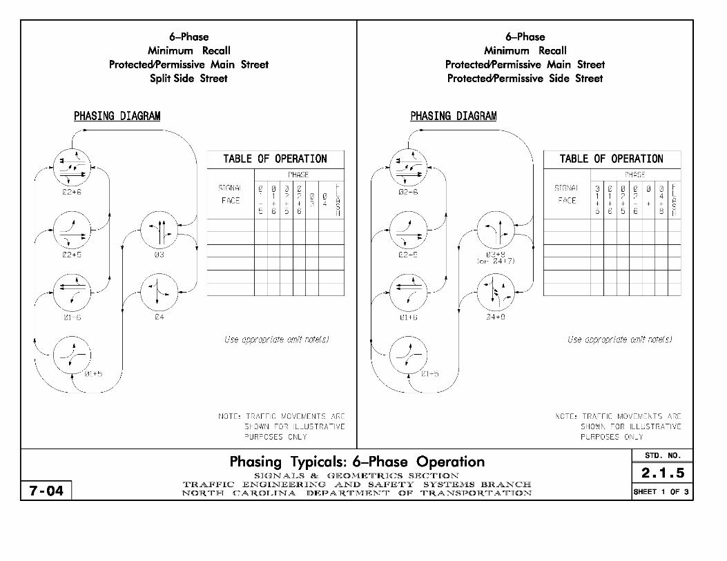
6-Phase 6-Phase Minimum Recall Minimum Recall
Protected1'ermissive Main Street Protected1'ermissive Main Street Split Side Street Protected1'ermissive Side Street
PHASING DIAGRAM PHASING DIAGRAM
~ TABLE OF OPERATION ~ TABLE OF OPERATION -~, ~,
T=: PHASE T=: PHASE
1212+5 SIGNAL 0 0 0 0 F 1212+5 SIGNAL 0 0 0 0 0 0 F
1 1 2 2 0 0 L 1 1 2 2 4 L FACE + + + + 3 4 A FACE + + + + + + A
S S
({j:Jj ({i~)< 5 6 5 6 H
~j (6)< 5 6 5 6 8 H
1212+5 03 02+5 03+8 (or 04+7)
r<t!/ ~{i}( ~<~}/ ({~br/ 04 04+8
\~~, Use appropriate omit note(s)
t~~~ Use appropriate omit note( s)
01 +5 1211+5
NOTE, TRAFFIC MOVEMENTS ARE NOTE, TRAFFIC MOVEMENTS ARE
SHOWN FOR ILLUSTRATIVE SHOWN FOR ILLUSTRATIVE PURPOSES ONLY PURPOSES ONLY
Phasing Typicals: 6-Phase Operation STD. NO.
2.1.5 SIGNALS Be GEOME11'RICS SEC11'ION
7-04 I 11'RAFFIC ENGINEERING AND SAFE11'Y SYS11'EMS BRANCH NOR11'H CAROLINA DEPAR 11'MEN11' OF 11'RANSPOR 11' A TION SHEET 1 OF 3

6-Phase Minimum Recall
Protected Main Street Split Side Street
6-Phase Minimum Recall
Protected Main Street Protectedil'ermissive Side Street
PHASING DIAGRAM PHASING DIAGRAM
1212+6
03
01+6 04
-r 01 +5
7-04
TABLE OF OPERATION PHASE
SIGNAL 0 0 0 0 F 1 1 2 2 0 0 L
FACE + + + + 3 4 A S 5 6 5 6 H
NOTE, TRAFFIC MOVEMENTS ARE SHOWN FOR ILLUSTRATIVE PURPOSES ONLY
02+6
1211+6
-r 01+5
03+8 (or 1214+7)
1214+8
Phasing Typicals: 6-Phase Operation SIGN ALS & GEOMETRICS SECTION
TRAFFIC ENGINEERING AND SAFETY SYSTEMS BRANCH NOR TH CAROLIN A DEPARTMENT OF TRANSPORTATION
TABLE OF OPERATION PHASE
SIGNAL 0 0 0 0 0 0 F 1 1 2 2 4 L
FACE A + + + + + + S 5 6 5 6 8 H
NOTE, TRAFFIC MOVEMENTS ARE SHOWN FOR ILLUSTRATIVE PURPOSES ONLY
STD. NO.
2.1.5 SHEET 2 OF 3

6-Phase Soft Recall
Protected Main Street Split Side Street
6-Phase Soft Recall
Protected Main Street ProtectedlPermissive Side Street
PHASING DIAGRAM PHASING DIAGRAM
/ ( I
/'
/
1212+5
1211+5
-}-01 +5
7-04
03
04
TABLE OF OPERATION PHASE
SIGNAL 0 0 0 0 F 1 1 2 2 0 0 L
FACE + + + + 3 4 A S 5 6 5 6 H
NOTE, TRAFFIC MOVEMENTS ARE
SHOWN FOR ILLUSTRATIVE PURPOSES ONLY
/ ( I
/ /'
1212+5
01+5
-}-1211+5
03+8 (or 04+7)
04+8
Phasing Typicals: 6-Phase Operation SIGN ALS Be GEOMETRICS SECTION
TRAFFIC ENGINEERING AND SAFETY SYSTEMS BRANCH NORTH CAROLINA DEPARTMENT OF TRANSPORTATION
TABLE OF OPERATION PHASE
SIGNAL 0 0 0 0 0 0 F 1 1 2 2 4 L
FACE A + + + + + + S 5 6 5 6 8 H
Use appropriate omit note(s)
NOTE, TRAFFIC MOVEMENTS ARE
SHOWN FOR ILLUSTRATIVE PURPOSES ONLY
STD. NO.
2.1.5 SHEET 3 OF 3
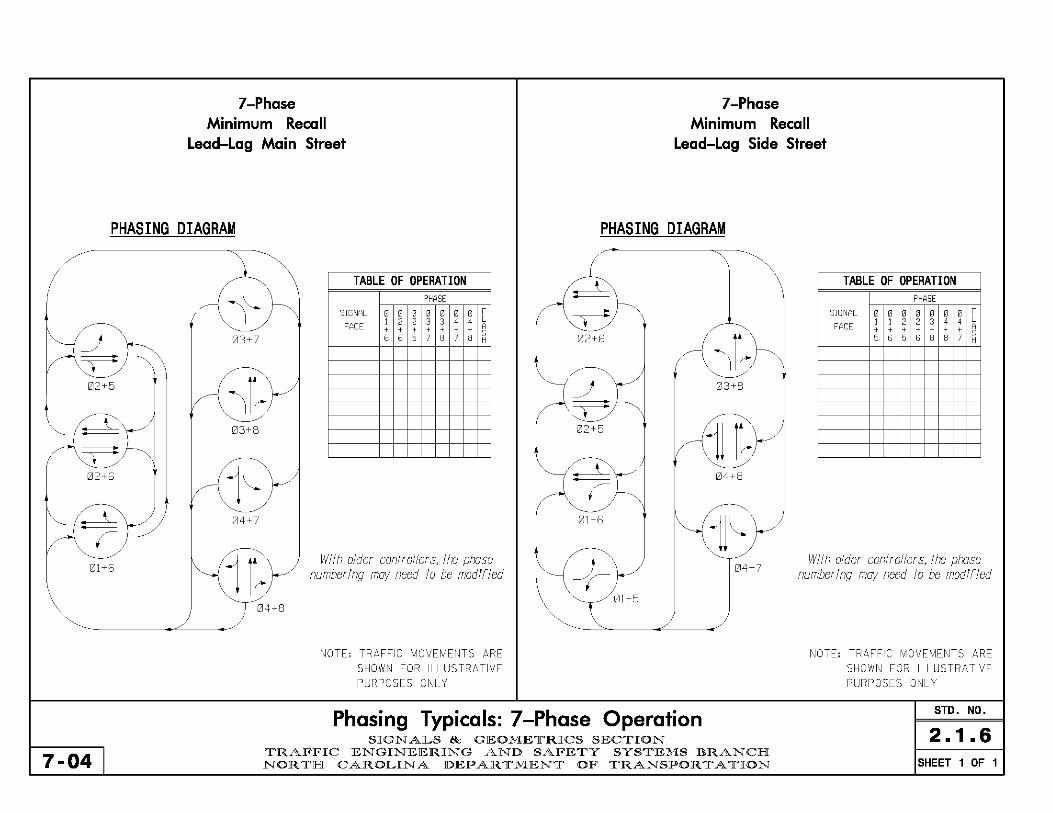
7-Phase Minimum Recall
Lead-Lag Main Street
7-Phase Minimum Recall
Lead-Lag Side Street
PHASING DIAGRAM PHASING DIAGRAM
1212+5
02+6
1211+6
7-04
03+7
03+8
04+7
TABLE OF OPERATION PHASE
SIGNAL 0 0 0 0 0 0 0 F 1 2 2 3 3 4 4 L
FACE , , , , , , , A S
6 6 5 7 8 7 8 H
With aider controiiers, the phase numbering may need to be modified
02+5
03+8
1212+5
1214+8
01 +5
-f- 1214+7
01 +5 04+8
NOTE, TRAFFIC MOVEMENTS ARE SHOWN FOR ILLUSTRATIVE PURPOSES ONLY
Phasing Typicals: 7-Phase Operation SIGN ALS & GEOMETRICS SECTION
TRAFFIC ENGINEERING AND SAFETY SYSTEMS BRANCH NOR TH CAROLIN A DEPARTMENT OF TRANSPORTATION
TABLE OF OPERATION PHASE
SIGNAL 0 0 0 0 0 0 0 F 1 1 2 2 3 4 4 L
FACE , , , , , , , A S 5 6 5 6 8 8 7 H
With older controllers, the phose numbering may need to be modified
NOTE, TRAFFIC MOVEMENTS ARE SHOWN FOR ILLUSTRATIVE PURPOSES ONLY
STD, NO,
2.1.6 SHEET 1 OF 1
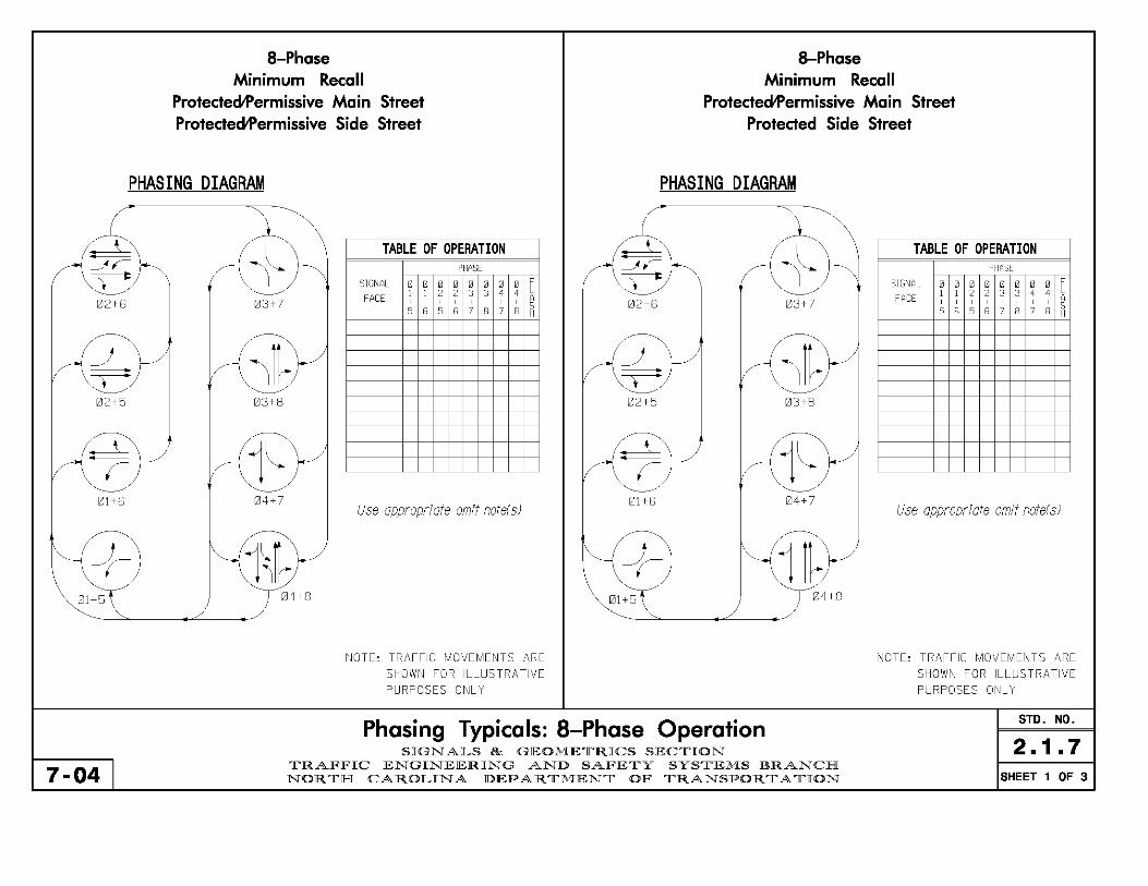
a-Phase Minimum Recall
Protected1'ermissive Main Street Protected1'ermissive Side Street
a-Phase Minimum Recall
Protected1'ermissive Main Street Protected Side Street
PHASING DIAGRAM PHASING DIAGRAM
~ -~,
~ 02+8
J ~ 02+5
~ r
1211+5
-f-01+5
7-04
II 03+7
11~ 03+8
~1l 04+7
~1\~ 04+8
TABLE OF OPERATION PHASE
SIGNAL 0 0 0 0 0 0 0 0 F 1 1 2 2 3 3 4 4 L
FACE , , , , , , , , A 5 5 6 5 6 7 8 7 8 H
Use appropriate omit note( s)
NOTE, TRAFFIC MOVEMENTS ARE
SHOWN FOR ILLUSTRATIVE PURPOSES ONLY
~ -~,
~ 02+5
J ~ 02+5
~ r
01+5
-f-1211+5
Phasing Typicals: a-Phase Operation SIGN ALS Be GEOMETRICS SECTION
II 03+7
11~ 03+8
~1l 1214+7
~11~ 04+8
TRAFFIC ENGINEERING AND SAFETY SYSTEMS BRANCH NORTH CAROLINA DEPARTMENT OF TRANSPORTATION
TABLE OF OPERATION PHASE
SIGNAL 0 0 0 0 0 0 0 0 F 1 1 2 2 3 3 4 4 L
FACE , , , , , , , , A S 5 6 5 6 7 8 7 8 H
Use appropriate omit note( s)
NOTE, TRAFFIC MOVEMENTS ARE
SHOWN FOR ILLUSTRATIVE PURPOSES ONLY
STD. NO.
2.1. 7 SHEET 1 OF 3

a-Phase Minimum Recall
Protected Main Street Protectedil'ermissive Side Street
a-Phase Minimum Recall
Protected Main Street Protected Side Street
PHASING DIAGRAM PHASING DIAGRAM
~
? 1212+6
_J ? 02+5
~ r
01+6
-f-1211+5
7-04
i l 03+7
il~ 03+8
~1l 04+7
~1\~ 04+8
TABLE OF OPERATION PHASE
SIGNAL 0 0 0 0 0 0 0 0 F 1 1 2 2 3 3 4 4 L
FACE , , , , , , , , A S
5 6 5 5 7 8 7 B H
NOTE, TRAFFIC MOVEMENTS ARE SHOWN FOR ILLUSTRATIVE PURPOSES ONLY
~
? 02+6
02+5
01+6
-f-01+5
Phasing Typicals: a-Phase Operation SIGN ALS & GEOMETRICS SECTION
i l 1213+7
il~ 03+8
~1l 1214+7
·1 1~ 1214+8
TRAFFIC ENGINEERING AND SAFETY SYSTEMS BRANCH NOR TH CAROLIN A DEPARTMENT OF TRANSPORTATION
TABLE OF OPERATION PHASE
SIGNAL 0 0 0 0 0 0 0 0 F 1 1 2 2 3 3 4 4 L
FACE , , , , , , , , A S
5 6 5 6 7 8 7 8 H
NOTE, TRAFFIC MOVEMENTS ARE SHOWN FOR ILLUSTRATIVE PURPOSES ONLY
STD. NO.
2.1. 7 SHEET 2 OF 3

a-Phase a-Phase Minimum Recall
Protected and ProtectecWermissive Main Street Protected and ProtectecWermissive Side Street
Soft Recall Protected Main Street Protected Side Street
PHASING DIAGRAM PHASING DIAGRAM
~ ----L T--:
02+5
J ~ 02+5
~ r
1211+5
-f-01+5
7-04
II 03+7
11~ 03+8
~1l 04+7
~l'l~ 04+8
TABLE OF OPERATION PHASE
SIGNAL 0 0 0 0 0 0 0 0 F 1 1 2 2 3 3 4 4 L
FACE , , , , , , , , A 5 5 6 5 6 7 8 7 8 H
Use appropriate omit note( s)
NOTE, TRAFFIC MOVEMENTS ARE
SHOWN FOR ILLUSTRATIVE PURPOSES ONLY
/'
/ ! ~ I
I ~ 02+5
02+5
01 +6
-f-01+5
Phasing Typicals: a-Phase Operation SIGN ALS Be GEOMETRICS SECTION
1213+7
1213+8
04+7
1214+8
TRAFFIC ENGINEERING AND SAFETY SYSTEMS BRANCH NORTH CAROLINA DEPARTMENT OF TRANSPORTATION
TABLE OF OPERATION PHASE
SIGNAL 0 0 0 0 0 0 0 0 F 1 1 2 2 3 3 4 4 L
FACE , , , , , , , , A S 5 6 5 6 7 8 7 8 H
NOTE, TRAFFIC MOVEMENTS ARE
SHOWN FOR ILLUSTRATIVE PURPOSES ONLY
STD. NO.
2.1. 7 SHEET 3 OF 3
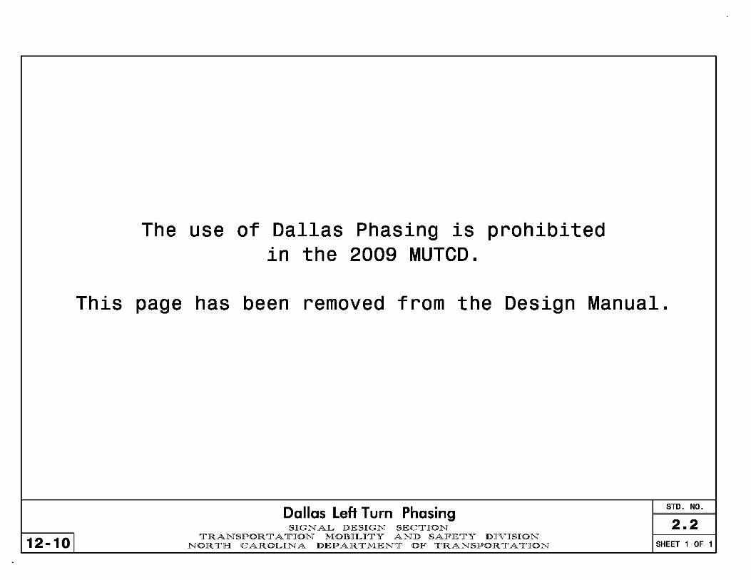
12-101
The use of Dallas Phasing is prohibited in the 2009 MUTeD.
This page has been removed from the Design Manual.
Dallas Left Turn Phasing SIGN AL DESIGN SECTION
TRANSPORTATION MOBILITY AND SAFETY DIVISION NORTH CAROLINA DEPARTMENT OF TRANSPORTATION
STD. NO.
2.2 SHEET 1 OF 1

Red Revert Backup Protection
Yellow Trap and Dynamic Backup Control
A "yellow trap" occurs when a traffic signal cycles directly from concurrent through phases to a fully protected phase opposing a permitted phase (also known as "backing up"). This situation is avoided in a signal design whenever possible. Typically, phase omits or forcing the signal to cycle through the side street (even if there are no vehicle calls) to serve the protected phase have been used to protect against a "yellow trap."
Red Revert
Red revert is a feature in 2070 Oasis software that allows the signal to cycle from a permissive left turn phase on the major street to a protected phase and avoid a "yellow trap." Red revert simulates an all red "dummy" phase by clearing the through phase(s) to red for a brief interval before cycling to the adjacent protected left turn phase and then returning to green again; the opposing through phase will stay red for the duration of the protected turning phase.
The time that the adjacent through phase displays red before returning to green is a function of the red revert time. Typically the red revert time is programmed to (at least) 5 seconds to avoid the appearance of improper operation.
Conditions for Use 1 . Used only with 2070 Oasis Software 2. Cannot be used with NEMA TS-1, TS-2,
170, or other 2070 software (such as SE-PAC, NAZTEC, or the Cary Signal System)
3. Used only on the major street (phases 2+6) 4. May be used when there is one or two protected/
permissive phases (1 and/or 5) on the major street 5. Use in conjuncion with 5 section (doghouse) heads. 6. Use in place of phase omit and clearing through the
side street. 7. Do NOT use with Railroad Preemption if the major
street is the approach that crosses the tracks and is used in the Track Clearance Phase.
When Used On Plans:
-Typically set red revert time for phase 2 (and/or 6) to 5.0 seconds.
-Default red revert time for all other phases is 2.0 seconds.
-Use the following note on plans: Enable backup protect for phase 2 (and/or 6) to allow the controller to clear from phase 2+6 to phase 2+5 (and/or 1+6) by progressing though an all red display.
Phasing Typicals: Red Revert Operation STD. NO.
2.3 7-09 I
SIGN AL DESIGN SECTION TRANSPORTATION MOBILITY AND SAFETY DIVISION
NORTlH CAROLINA DEPARTMENT OF TRANSPORTATION SHEET 1 OF 3

7-09
3 Phase Minimum Recall
Protected1'ermissive Left One Direction Permissive Only Left Other Direction
• \
02+6
PHASING DIAGRAM
02+5 (or 01+6)
04+8
Use Red Revert for Phase 2 /6 if 1+6 is used)
NOTE, TRAFFIC MOVEMENTS ARE SHOWN FOR ILLUSTRATIVE PURPOSES ONLY
4 Phase Minimum Recall
Protected1'ermissive Left One Direction of Major Street Permissvie Left on Other Direction of Major Street
Protected1'ermissive Side Street OR Split Side Street
PHASING DIAGRAM
02+6
)
=v= 02+5
(or 01+6)
03+8 (or 04+7
or 03 Spllt S,ds)
04+8 (01'" 04 Sph t Slde)
Use Red Revert for Phose 2 (6 If 1+6 Is used) Use appropriate omit note(s) for side street
NOTE, TRAFFIC MOVEMENTS ARE SHOWN FOR ILLUSTRATIVE PURPOSES ONLY
Phasing Typicals: Red Revert Operation STD. NO.
2.3 SIGN AL DESIGN SECTION TRANSPORTATION MOBILITY AND SAFETY DIVISION
NORTH CAROLINA DEPARTMENT OF TRANSPORTATION SHEET 2 OF 3
7-09
02+5
!ZIl+6
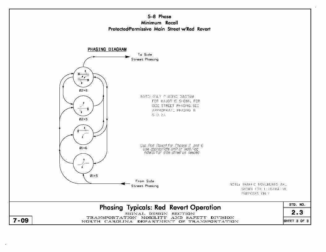
5-8 Phase Minimum Recall
ProtectecWermissive Main Street wiRed Revert
PHASING DIAGRAM To SIde
Street Phosmg
NOTE, ONLY PHASING DIAGRAM
FOR MAJOR IS SHOWN. FOR SIDE STREET PHASING, SEE APPROPPIATE PHASING IN STD. 2.1.
Use Red Revert for Phases 2 ond 6 Use appropriate omit or iead/iag note(s) for side street as needed
From SIde
Street Phasmg
Phasing Typicals: Red Revert Operation
NOTE, TRAFFIC MOVEMENTS ARE
SHOWN FOR ILLUSTRATIVE PURPOSES ONLY
STD. NO.
2.3 SIGN AL DESIGN SECTION TRANSPORTATION MOBILITY AND SAFETY DIVISION
NORTlH CAROLINA DEPARTMENT OF TRANSPORTATION SHEET 3 OF 3

3 Phase Minimum Recall
Protected1'ermissive Left One Direction Permissive Only Left Other Direction
PHASING DIAGRAM
Phose 5 may be logged (Phose Ilf 1+6 Is used)
THIS ASSUMES A 4 SECTION FYA IS USED FOR THE LEFT TURN ON ONE APPROACH (PHASE 51 AND A 3 SECTION FYA IS USED FOR THE LEFT TURN ON THE OTHER APPROACH OF MAIN STREET
NOTE, TRAFFIC MOVEMENTS ARE SHOWN FOR ILLUSTRATIVE PURPOSES ONLY
TABLE OF OPERATION PHASE
SIGNAL 0 0 0 F 2 2 4 L
FACE A + + + S 5 6 8 H
51 - ~ --R- 4-
61 + + --R- 4-
4 Phase Minimum Recall
Protected1'ermissive Left One Direction of Main Street Permissvie Left on Other Direction of Main Street
Protected1'ermissive Side Street OR Split Side Street
PHASING DIAGRAM
1212+6 03+8 (or 1214+7
or 1213 Split Side)
04+8 (or flJ4 Sph t Slde)
Phose 5 may be logged (Phose I if 1+6 is used)
THIS ASSUMES A 4 SECTION FYA IS USED FOR THE LEFT TURN ON ONE APPROACH (PHASE 5) AND A 3 SECTION FYA IS USED
FOR THE LEFT TURN ON THE OTHER APPROACH OF MAIN STREET
NOTE, TRAFFIC MOVEMENTS ARE SHOWN FOR ILLUSTRATIVE PURPOSES ONLY
TABLE OF OPERATION PHASE
SIGNAL 0 0 0 0 F 2 2 3 4 L
FACE A + + + + S 5 6 8 8 H
51 - + --R- --R- 4-
61 + ~ --R- --R- 4-
STD. NO. Phasing Typicals: Flashing Yellow Arrow
SIGN AL DESIGN SECTION TRANSPORTATION MOBILITY AND SAFETY DIVISION
NORTH CAROLINA DEPARTMENT OF TRANSPORTATION
2.4 12-10 SHEET 1 OF 2

12-10
02+6
02+5
01+6
5-8 Phase Minimum Recall
Protectedil'ermissive Main Street
PHASING DIAGRAM
01+5
To SIde
Street Phosmg
THIS ASSUMES A 4 SECTION FYA IS USED FOR THE LEFT TURN ON BOTH APPROACHES OF THE MAIN STREET
NOTE, ONLY PHASING DIAGRAM FOR MAJOR IS SHOWN. FOR SIDE STREET PHASING, SEE APPROPRIATE PHASING IN STD. 2.1.
Use lead/la9 notes for Phases I and 5 Use appropriate omit or lead/lag note(s) for side street as needeC!
From SIde
Street Phoslng
Phasing Typicals: Flashing Yellow Arrow
TABLE OF OPERATION PHASE
SIGNAL 0 0 0 0 0 F 1 1 2 2 4 L
FACE A + + + + + S 5 6 5 6 8 H
11 - - ~ -+ -oft 4
51 - -+ - -+ -oft 4
NOTE, TRAFFIC MOVEMENTS ARE SHOWN FOR ILLUSTRATIVE PURPOSES ONLY
STD. NO.
2.4 SIGN AL DESIGN SECTION TRANSPORTATION MOBILITY AND SAFETY DIVISION
NORTlH CAROLINA DEPARTMENT OF TRANSPORTATION SHEET 2 OF 2
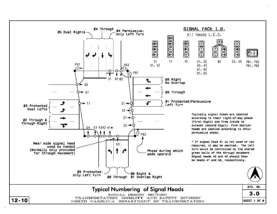
fIl5 Dual !1l4 Through ..
Rights 1 !1l4 Perml.SSl.ve~ £ only Left Turn
SIGNAL FACE 1.0.
P61
~
I I I
~ ~ * ~ I ~2
It- l r"-. it P81
~ @ (f)
31 51. 52
® All
@
~ ® @ ;) EB =
11 41
~--.l...."" 31 81 82 --t···---'t....------::}-!1l6 Right 62 1-_____ No Overlap ->- 61 - -} !1l6 Through -
Heads L.E.D.
®
~ @ @@ © @@
c= = 21. 22 82 42. 43 61. 62 81. 83
~ @ ~f!i" ~I @ ........
I " I
53. 54 P61. P62 P81. P82
!1l5 Protected { _ j
-
Dual Lefts j
r- 11 } !1l1 Protected/Permissive .A.L---'------"-- Left Turn 51- ..
52~
!1l2 Through & { _ - -
Through-Right T 21-<>
-
22-______ ...L+-'5""4'--.;5::,:3 4342 41 *
e-(1)-Ol'--\CJK)1--c1>----O~----If---e'"'.9 P 8 2
r ~ Near side signal head ______ --- 83 used as neede~ _______
(Normally only provided ... t ,. Phase during for through movement) peds operate
which
!1l3 Protected- y r ~!1lS Right & only Left Turn !1lS Through !1l1 Overlap Right
Typical Numbering of Signal Heads SIGNAL DESIGN SEC,][,ION
Typically signal heads are labeled according to their right-af-way phase (first digit) and from inside to outside (second digit). Five section heads are labeled according to their permissive phase.
* If signal head 41 is not used or not required, it may be omitted. The left turn would be controlled by the shared green balls of the through movement. Signal heads 42 and 43 should then be heads 41 and 42, respectively.
STD. NO.
3.0 12-101
']['RANSPOR '][' A ,][,ION MOBILI,][,Y AND SAF'E,][,Y DIVISION NOR ,][,H CAROLINA DEPAR ,][,MEN,][, OF' ']['RANSPOR '][' A ,][,ION SHEET 1 OF 6

Signal Head Types
CONFIGURATION o mR
3-Section 4-Section Vertical
USAGE
©
All situations where other signal heads are not recommended
3-Section
Permitted Turn
3-Section
Protected Turn
Split Side Street RR Clearance Phasing
EV Preempt Phasing
4-Section
Protected I Permissive
Turn
Protected I Permissive
Turn
PLACEMENT Lane Line or Lane ct. Lane ct. Lane ct. Lane Line
or Lane 't Lane ct. Lane Line
12-101
Number of Signal Faces A minimum of two signal faces is required for the through movement. This total includes the through signal face belonging to the 5-section "shared" head that may control adjacent left or right turn lanes.
Clarification: A 5-section head is an assembly of 2 signal faces which share a common red ball indication. See example below.
, __ ~ /-_ 'R __ ,
!~ '::@~II~ ::~". '\ : f-:,'@ G ;:@ ~ I '\ ': I
I " " ' I I, I, I I I \ r, I
" : I I \ I
, I I ' , , I I I I I I I I I I J
I I I I : :
:t i :~: I I I I I I \ I
\ I I ' I~_~ 1,_,,1
This approach display has 2 signal heads each of which is comprised of 2 signal faces for a total of 4 signal faces. Two of the faces belong to the through move, and one each belongs to the left and right turns. Because the center two faces control the through (major) move, it is in conformance with the above requirement.
Per Section 40.11 of the 2009 MIiTeD, if the 85th percentile, posted, statutory, or design speed is 45 MPH or more, one signal head should be used per each through lane on the approach.
General Guidelines for Signal Head Usage SIGNAL DESIGN SEClrION
STD. NO.
3.0 lrRANSPOR 11' A lrION MOBILIlrY AND SAlFElrY DIVISION
NORlrH CAROLINA DEPARlrMENlr OlF lrRANSPORlrAlrION SHEET 2 OF 6
12-101
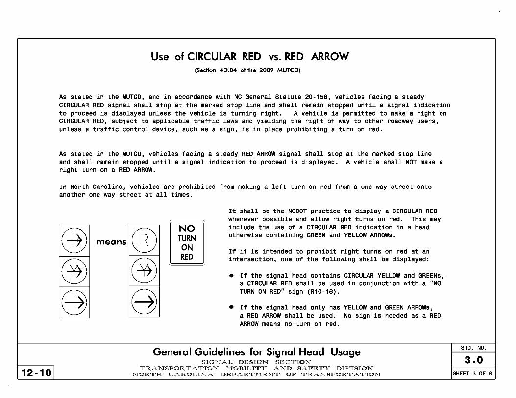
Use of CIRCULAR RED vs. RED ARROW (Section 40.04 of the 2009 MUTeD)
As stated in the MUTCD, and in accordance with NC General Statute 20-158, vehicles facing a steady CIRCULAR RED signal shall stop at the marked stop line and shall remain stopped until a signal indication to proceed is displayed unless the vehicle is turning right. A vehicle is permitted to make a right on CIRCULAR RED, subject to applicable traffic laws and yielding the right of way to other roadway users, unless a traffic control device, such as a sign, is in place prohibiting a turn on red.
As stated in the MUTCD, vehicles facing a steady RED ARROW signal shall stop at the marked stop line and shall remain stopped until a signal indication to proceed is displayed. A vehicle shall NOT make a right turn on a RED ARROW.
In North Carolina, vehicles are prohibited from making a left turn on red from a one way street onto another one way street at all times.
means ® ® 8
NO TURN ON RED
It shall be the NCDOT practice to display a CIRCULAR RED whenever possible and allow right turns on red. This may include the use of a CIRCULAR RED indication in a head otherwise containing GREEN and YELLOW ARROWs.
If it is intended to prohibit right turns on red at an intersection, one of the following shall be displayed:
• If the signal head contains CIRCULAR YELLOW and GREENs, a CIRCULAR RED shall be used in conjunction with a "NO TURN ON RED" sign (R10-16).
• If the signal head only has YELLOW and GREEN ARROWs, a RED ARROW shall be used. No sign is needed as a RED ARROW means no turn on red.
General Guidelines for Signal Head Usage SIGNAL DESIGN SEC,][,ION
']['RANSPOR '][' A ,][,ION MOBILI,][,Y AND SAF'E,][,Y DIVISION NOR ,][,H CAROLINA DEPAR ,][,MEN,][, OF' ']['RANSPOR '][' A ,][,ION
STD. NO.
3.0 SHEET 3 OF 6

Use of 4 Section (ProtectedtPermissive) Flashing Yellow Arrow Signal Faces Traditionally, a 5 section "doghouse" head has been used for protected/permissive turning movements. This head has a combination of CIRCULAR and ARROW displays, and is often used as "shared" head between the turning movement and the through movement, although the head could be used exclusively for the turning movement.
The new preferred display for protected/permissive left turns is the Flashing Yellow Arrow (FYA). This head is intended to be an exclusive head for the turn lane and displays only ARROW indications. A FYA is displayed for the permissive movement, instead of the traditional CIRCULAR GREEN. Vehicles may make the turn indicated by the FYA after yielding to pedestrians and conflicting movements. A solid GREEN ARROW is used to indicated a protected movement. The FYA head should be centered over the turn lane(s). Note that the FYA head is an exclusive for the left turn, and 2 signal heads containing CIRCULAR REO, YELLOW, and GREEN displays are still required for the through movement.
12-101
II~ t
mRA o y @ @ G @
II~ t r
This approach display has 2 signal heads each of which is comprised of 2 signal faces for a total of 4 signal faces. Two of the faces belong to the through move, and one each belongs to the left and right turns. Because the center two faces control the through (major) move, it is in conformance with the requirement for 2 signal faces for the through movment. The 5 section head may still be used in limited situations.
FYAs for left turns should be used: - When the turn lanes are offset (separated from the through lanes) - When the opposing travel lanes use (3-section or 4-section) FYAs
or fully protected (single or dual) lefts to avoid "yellow trap" - Along corridors, where other FYA displays are used for left turns - At Railroad preempt locations, which eliminate the need for
blankout signs When FYAs are used for left turns, the yellow and red clearance times
should be the same for concurrent through phases (2+6 and/or 4+8).
NOTE: FYAs for right turns may be used on a limited basis as determined by Engineering the FYA head should replace the 5 section shared "doghouse" head for the right turn. necessary to add an addtional 3 section CIRCULAR head for the through movement.
judgment. When used, As a result, it may be
General Guidelines for Signal Head Usage SIGNAL DESIGN SEClrION
lrRANSPOR 11' A lrION MOBILIlrY AND SAlFElrY DIVISION NORlrH CAROLINA DEPARlrMENlr OlF lrRANSPORlrAlrION
STD. NO.
3.0 SHEET 4 OF 6

Use of 3-Section (Permissive) Left Turn Flashing Yellow Arrow Signal Faces Traditionally, a CIRCULAR GREEN display has been used to indicate a permissive movement. Vehicles may turn right or left as allowed on a CIRCULAR GREEN after yielding to pedestrians and conflicting movements.
mR
@ ®
II~
mR
@ ®
A CIRCULAR GREEN may be used as a shared display with the through movement. In the example shown, the signal heads are mounted over the lane lines (extended) and are classified as shared heads, because the head display is "shared" by vehicles in adjacent lanes (left and through or the through and through·right). The two "shared" heads meet the requirements for through signal displays. When an FYA is not used for the left turn display, the signal heads should be mounted over the lane line extended instead of as shown in Std. 3.2. IN NO CASE shall a CIRCULAR GREEN display be located directly over or in front of a left turn lane.
Optional Permissive Left Turn Signal Display
An optional display for permissive turns is the Flashing Yellow Arrow (FYA). Vehicles observing an FYA may make the turn indicated by the flashing yellow arrow after yielding to pedestrians and conflicting movements, the same as a CIRCULAR GREEN. The FYA head should be centered over the turn lane(s). Note that the FYA is an exclusive head for the left turn, and 2 signal heads containing CIRCULAR RED, YELLOW, and GREEN displays are still required for the through movement.
II~
12-101
mR
@ ®
t
mR
@ ®
FYAs for left turns should be used: - When the turn lanes are offset (separated from the through lanes) - When the opposing travel lanes use (3-section or 4-section) FYAs
or fully protected (single or dual) lefts to avoid "yellow trap" - Along corridors, where other FYA displays are used for left turns - At Railroad preempt locations, which eliminate the need for
blankout signs When FYAs are used for left turns, the yellow and red clearance times
should be the same for concurrent through phases (2+6 and/or 4+8).
FYAs for right turns may be used on a limited basis as determined by Engineering judgment.
General Guidelines for Signal Head Usage 3.0
STD. NO.
SIGNAL DESIGN SEC,][,ION ']['RANSPOR '][' A ,][,ION MOBILI,][,Y AND SAF'E,][,Y DIVISION
NOR ,][,H CAROLINA DEPAR ,][,MEN,][, OF' ']['RANSPOR '][' A ,][,ION SHEET 5 OF 6

Programming for Flashing Operation of Signal Heads
Signals typically may flash during certain types of malfunctions or equipment failures. For statewide consistency, traffic signal heads should be set to flash the displays shown in the event of flashing operation:
~ I j® ®
~ I ~ ®
i ~ CD ~
SIGNAL HEAD ® ® 0 © ® 0 @ 0 @ @ 8 ® © ® ~ © @ © @ 8)
~ ~ = ~
~
MAJOR STREET .p- -¥- Y Y -¥- Y --¥- Y --¥- --¥-
MINOR STREET .p- .p- R R .p- R R R R R
Flashing display does not change if a RED ARROW is used in place of a CIRCULAR RED for right turn displays.
At some intersections, such as those utilizing Railroad Preemption, engineering judgement may be used to modify or alter the flashing operation. This modification may include flashing the minor street through movements yellow and the main street red or using a red flash on all approaches (equivalent of an all way stop).
Program all signal heads on the same approach to flash concurrently.
General Guidelines for Flashing Signal Heads STD. NO.
3.0 SIGNAL DESIGN SEClrION
12-101 lrRANSPOR 11' A lrION MOBILIlrY AND SAlFElrY DIVISION
NORlrH CAROLINA DEPARlrMENlr OlF lrRANSPOR 11' A lrION SHEET 6 OF 6

12-10
Allowable Signal Head Distance from Stopbar (Section 40.14 of the 2009 MUTeD)
NOTE: All signal heads shall be 12" indications unless they meet the Option requirements of Section 40.07 of the 2009 MUTeD.
> 180ft (5Sm): Requires supplemental near-side head
> 150ft (45m): Consider supplemental near-side head
------lh-l-+ > 120ft (35m): Requires 12" signal head
< 40ft (12m): Too close to stop line (Not applicable for near-side heads)
NOTE: where the nearest signal face is located betwBen 150 and 180 ft (45 and 55 m) beyond the stop line, use engineering judgement to determine if a near side signal head would be beneficial.
MUTeD Requirements for Signal Heads STD. NO.
3.1 SIGNAL DESIGN SEC1['ION 1['RANSPOR 1[' A 1['ION MOBILI1['Y AND SAlFE1['Y DIVISION
NOR 1['H CAROLINA DEPAR 1['MEN1[' OlF 1['RANSPOR 1[' A 1['ION SHEET 1 OF 2

Speed mph (km/hr)
20 (32) 25 (40) 30 (48) 35 (56) 40 (64) 45 (72) 50 (80) 55 (88) 60 (96)
12-10
Min. Sight Distance X ft (m)
175 (55) 215 (65) 270 (85) 325 (100) 390 (120) 460 (140) 540 (165 ) 625 (195 ) 715 (220)
Signal Face Visibility Parameters
, (3m) , \~
~\ +
~%:iJ
To conform to section 40.13 of the 2009 MUTeD, locate one, and preferably both, signal heads within a cone of vision extending 20 degrees to the left and right of the centerline of all the approach lanes in the direction of travel.
TO conform to section 40.12 of the 2009 MUTeD, the driver should be able to continuously view the signal face from the minimum sight distance for the 85th percentile speed.
Where this visibility requirement cannot be met, erect a suitable sign (such as a Signal Ahead Sign) to warn approaching traffic (Section 40.12 of the 2009 MUTeD) or install a supplemental near side head.
MUTeD Requirements for Signal Heads 3.1
STD. NO.
SIGNAL DESIGN SEClrION lrRANSPOR 11' A lrION MOBILIlrY AND SAlFElrY DIVISION
NORlrH CAROLINA DEPARlrMENlr OlF lrRANSPORlrAlrION SHEET 2 OF 2

CASE 1 CASE 2
Standard Main or Side Street Signal Head Configuration
Standard Main or Side Street Signal Head Configuration
1A - Permissive Only
1 B - Protected I Permissive Left Turn
12-101
Lone
2A - Permissive Only Left Turn
• Optional Head
2B - Protected I Permissive Left Turn
2C - Protected Left Turn
Lone
Signal Head Approach Displays and Alignment SIGNAL DESIGN SEC1['ION
1['RANSPOR 1[' A 1['ION MOBILI1['Y AND SAlFE1['Y DIVISION NOR 1['H CAROLINA DEPAR 1['MEN1[' OlF 1['RANSPOR 1[' A 1['ION
1'~~:o'l I
Lone II
I
STDo NOo
3.2 SHEET 1 OF 24

3A -
3AR -
12-101
CASE 3 (1 OF 2)
Standard Main or Side Street Signal Head Configuration
Permissive Only
~ ~ Left Turn (J) (J) © ©
1 1
Lone Lone
It It
Permissive Only
~ "'" ",!@~ Left Turn (J) with Right (J)@
Turn Overlap © ©8 -'='- '-'='-
I' ~~: 'I Lone Line
I
4 ,.
38 -
38R -
I
CASE 3 (2 OF 2)
Standard Main or Side Street Signal Head Configuration
Protected I (§5
~ Permissive (J) Left Turn ®(J) B© © '-'='-I-'='-
1
Lone Lone
It It
Protected I = "" ""@"" ""@"" Permissive
Left Turn ® (J)(J) @ with Right B ©© @ Turn Overlap '-'='- -'='- '-'='- -'='-
I' ~~:o 'I Lone Line
I
4 ,. Signal Head Approach Displays and Alignment
SIGN AL DESIGN SECTION TRANSPOR T A TION MOBILITY AND SAlFETY DIVISION
NORTH CAROLINA DEPARTMENT OlF TRANSPORTATION
STDo NOo
3.2 SHEET 2 OF 24

CASE 4 CASE 5 (1 OF 3)
Standard Main or Side Street Signal Head Configuration
Standard Main or Side Street Signal Head Configuration
4A - Permissive Only Left Turn
48 - Protected!
12-101
Permissive Left Turn
~R
CD ©
Lone
Il
~R
CD ©
~R
CD ©
I
Lone
Il
I
5A - Permissive Only Left Turn
* Optional Head
5AR - Permissive Only Left Turn with Right Turn Overlap
* Optional Head
Lone Il
Signal Head Approach Displays and Alignment SIGNAL DESIGN SECTION
TRANSPORTATION MOBILITY AND SAlFETY DIVISION NORTH CAROLINA DEP AR TMENT OlF TRANSPORTATION
IR
CD ©
I
Lone
t
IR
CD ©
Lone
STD. NO.
3.2 SHEET 3 OF 24
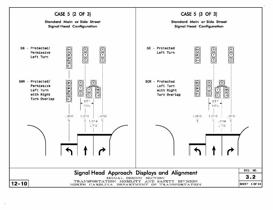
58 -
58R -
12-101
CASE 5 (2 OF 3) CASE 5 (3 OF 3)
Standard Main or Side Street Signal Head Configuration
Standard Main or Side Street Signal Head Configuration
Protected! Permissive Left Turn
Protected! Permissive Left Turn with Right Turn Overlap
~
~ ~ 5C - Protected
~ ® CD CD Left Turn
® ~ © © ® B ~
I
~ ~Ji; 5CR - Protected
~ ® CDCD@ Left Turn
® with Right ~ ©©B Turn Overlap ® B ~ ~
~ 8ft
I
mino
I Lone Lone Lone Lone
It It Lone It It
I
Line
I I
t Signal Head Approach Displays and Alignment
SIGNAL DESIGN SEClrION lrRANSPOR 11' A lrION MOBILIlrY AND SAlFElrY DIVISION
NORlrH CAROLINA DEPARlrMENlr OlF lrRANSPORlrAlrION
~ ~ CD CD © ©
~ Z§5
CD "" CD @ © © 85 = ~
8ft mino
I Lone Lone
It Lone It
I
Line
I I
t STD. NO.
3.2 SHEET 4 OF 24
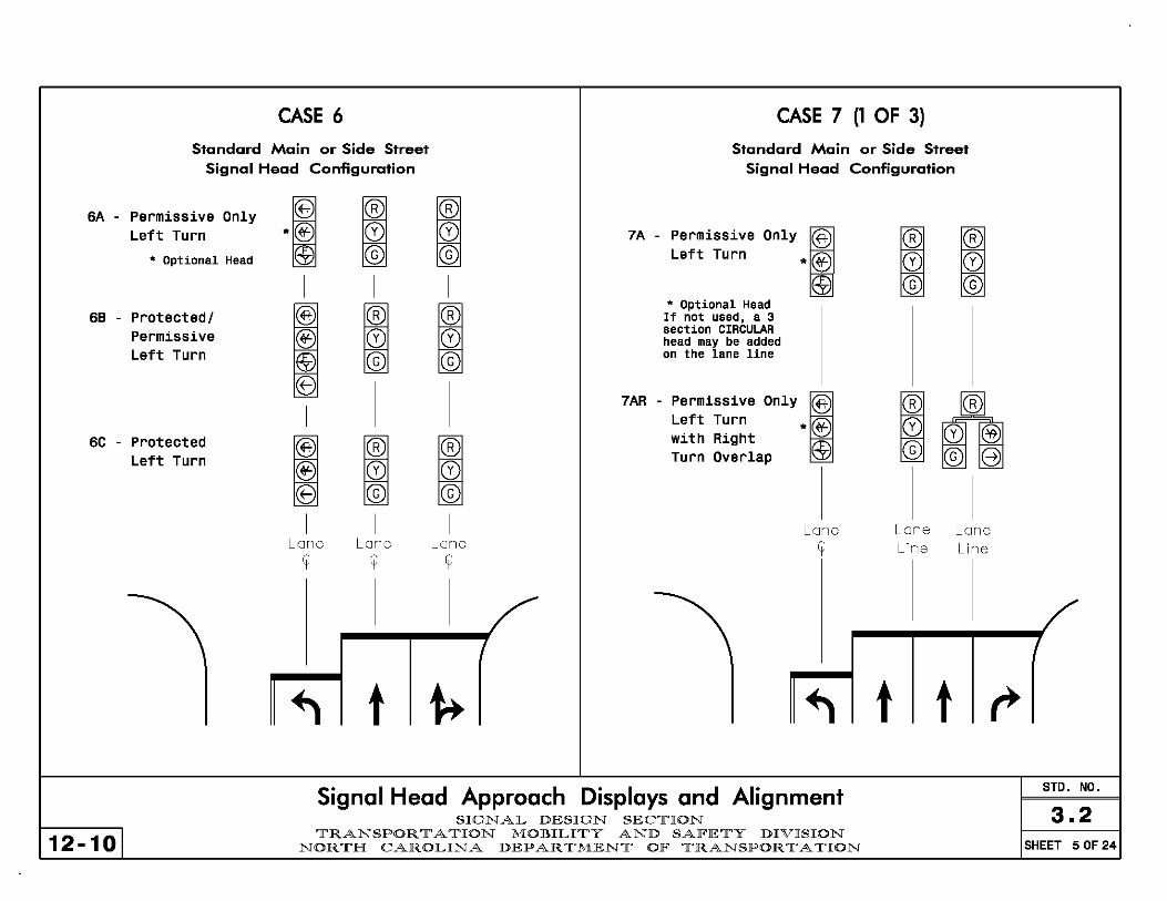
6A -
68 -
6e -
12-101
CASE 6 CASE 7 (1 OF 3)
Standard Main or Side Street Standard Main or Side Street Signal Head Configuration Signal Head Configuration
Permissive Only Left Turn
• Optional Head
Protected I Permissive Left Turn
Protected Left Turn
i ~ ~ *~ 0) 0) 7A -""",,., "" I@, © © Left Turn * ® I I I
@
®
~ ~ * Optional Head If not used, a 3
® 0) 0) section CIRCULAR head may be added
~ © © on the lane line
B I I
~ 7AR -""",,., """ I' I Left Turn * ®
~ ~ ~ with Right Turn Overlap @
® 0) 0) ® © ©
I I I Lone Lone Lone Lone
It It It
t Signal Head Approach Displays and Alignment
SIGNAL DESIGN SEC1['ION 1['RANSPOR 1[' A 1['ION MOBILI1['Y AND SAlFE1['Y DIVISION
NOR 1['H CAROLINA DEPAR 1['MEN1[' OlF 1['RANSPOR 1[' A 1['ION
~ ~ 0) 0) © ©
Z§5
~ 0) 0) @ © © B = ~
I
Lone Lone Line Line
t t STD. NO.
3.2 SHEET 5 OF 24

7B -
7BR -
12-101
CASE 7 (2 of 3) CASE 7 (3 OF 3)
Standard Main or Side Street Signal Head Configuration
Standard Main or Side Street Signal Head Configuration
Protected! ® Permissive ® Left Turn @ e ~
I
Protected! ® Permissive Left Turn ® with Right ® Turn Overlap 8 -=
I
Lone It
~ ~ 7C - Protected
~ CD CD Left Turn
® © © ®
~ (§5 7CR - Protected
~ Left Turn CD CD@ with Right ® © ®e Turn Overlap ®
'-'='- -=
I
Lone Lone Lone Line Line It
t t Signal Head Approach Displays and Alignment
SIGNAL DESIGN SEClrION lrRANSPOR 11' A lrION MOBILIlrY AND SAlFElrY DIVISION
NORlrH CAROLINA DEPARlrMENlr OlF lrRANSPORlrAlrION
~ ~ CD CD © ©
~ (§5
CD CD@ © ®B -= '-'='-
I
Lone Lone Line Line
t t STD. NO.
3.2 SHEET 6 OF 24

CASE 8 (1 OF 2) (Speeds less than 45 MPH)
Standard Main or Side Street Signal Head Configuration
" -""",, .. '"" I®I Left Turn ® .~
• Optional Head EB
88 - Protected! Permissive Left Turn
8C - Protected Left Turn
I
® ® EB E5 T ~ tfj
~R
CD ®
I
~R
CD ®
~R
CD ®
I
~R
CD ®
I
~R
CD ®
~R
CD ®
I
CASE 8 (2 OF 2) (Speeds 45 MPH or above)
Standard Main or Side Street Signal Head Configuration
..., -.,',',',., '"" I®I Left Turn ® . ~
• Optional Head EB 8845 - Protected!
Permissive Left Turn
8C45 - Protected Left Turn
I
® ® ~ ZB T ~ tfj
~R
CD ®
I
~R
CD ®
~R
CD ®
I
~R
CD ®
I
~R
CD ®
~R
CD ®
I
~R
CD ®
I
~R
CD ®
~R
CD ®
I
Lone Lone Lone Lone Lone
Lone
It
12-101
Line Line Lone
It
t t t. Signal Head Approach Displays and Alignment
SIGNAL DESIGN SEC1['ION 1['RANSPOR 1[' A 1['ION MOBILI1['Y AND SAlFE1['Y DIVISION
NOR 1['H CAROLINA DEPAR 1['MEN1[' OlF 1['RANSPOR 1[' A 1['ION
t STD. NO.
3.2 SHEET 7 OF 24

CASE 9 (1 OF 3)
Standard Main or Side Street Signal Head Configuration
9A - Permissive
~ m m m Left Turn .® 0 0 0
• Optional Head EB © © ©
9AR - Permissive
~ m m ® Left Turn
with Right .® 0 0 ~ @ Turn Overlap EB © © @ @
-""'-• Optional Head
Lone Lone Lone Lone Line Line Line
t t t
9B -
9BR -
CASE 9 (2 OF 3)
Standord Main or Side Street Signol Heod Configurotion
Protected! ~
m m I Permissive Left Turn ® 0 0 0
'® © © © e -'="
I
Protected! @
m I ® Permissive Left Turn ® 0 0 0 @ with Right ® © © ® @ Turn Overlap 8 """- --'='--
"""-
Lone Lone Lone LIne Line Line
Lone It
t t t Signal Head Approach Displays and Alignment
SIGNAL DESIGN SEClrION
/'
STD. NO.
3.2 12-101
lrRANSPOR 11' A lrION MOBILIlrY AND SAlFElrY DIVISION NORlrH CAROLINA DEPARlrMENlr OlF lrRANSPORlrAlrION SHEET 8 OF 24

CASE 9 (3 OF 3) CASE 10 (1 OF 2)
Standard Main or Side Street Signal Head Configuration
(Speeds less than 45 MPH)
Standard Main or Side Street Signal Head Configuration
9C - Protected Left Turn
9CR - Protected Left Turn with Right Turn Overlap
12-101
Lone
It
t
~R
CD ©
~R
CD ©
I
Lone LIne
t
~R
CD ©
~R
CD ©
Lone LIne
~R
CD ©
= ",l®""
CD@ ©8 ~I~
t
Lone Line
10A - Permissive Left Turn
• Optional Head
10B - Protected! Permissive Left Turn
10C - Protected Left Turn
t Signal Head Approach Displays and Alignment
SIGNAL DESIGN SEC1['ION
~ ~
I
~ ~
I
~ ~
I
Lone LIne
I
1['RANSPOR 1[' A 1['ION MOBILI1['Y AND SAlFE1['Y DIVISION NOR 1['H CAROLINA DEPAR 1['MEN1[' OlF 1['RANSPOR 1[' A 1['ION
t
IR
CD ©
I
~R
CD ©
~ ~
I
~ ~
I I
~ ~ ~ ~ I I
Lone Lone LIne Une
I I
STD. NO.
3.2 SHEET 9 OF 24

CASE 10 (2 OF 2) (Speeds 45 MPH or above)
Standard Main or Side Street Signal Head Configuration
10A45 - Permissive Left Turn
• Optional Head
10B45 - Protected! Permissive Left Turn
10C45 - Protected Left Turn
Lone
It
I
~R
CD ©
I
~R
CD ©
I
~R
CD ©
I
Lone
It
I
t
~R
CD ©
I
~R
CD ©
I
IR
CD ©
I
Lone
It
I
t
~R
CD ©
I
~R
CD ©
I
~R
CD ©
I
Lone
It
I
~R
CD ©
I
~R
CD ©
I
~R
CD ©
I
Lone
It
I
CASE 11 Main or Side Street
Signal Head Configuration for Dual Left Turn Movements
11A - Protected! Permissive Left Turn
11 B - Protected Left Turn
Lone
It
~R
CD ©
Lone Lone
It
I
I
Signal Head Approach Displays and Alignment
12-101 SIGNAL DESIGN SEClrION
lrRANSPOR 11' A lrION MOBILIlrY AND SAlFElrY DIVISION NORlrH CAROLINA DEPARlrMENlr OlF lrRANSPORlrAlrION
STO. NO.
3.2 SHEET 10 OF 24

CASE 12 CASE 13 (1 OF 2) Main or Side Street
Signol Heod Configurotion for Duol Left Tum Movements
Main or Side Street Signal Head Configuration
for Dual Right Turn Movements
12A - Protected! Permissive Left Turn
128 - Protected Left Turn
12-101
Lone Lone
For thru and
right lane
signal heads,
see corres-
ponding
diagram for
exclusive
left turns
(Cases 5-10)
t
13A -
13AP -
Permissive Left, No Right Turn Overlap, with Signs
Permissive Left, No Right Turn Overlap, with Peds, No Signs
Lone Il Lone
Line
Signal Head Approach Displays and Alignment SIGNAL DESIGN SECTION
TRANSPORTATION MOBILITY AND SAlFETY DIVISION NORTH CAROLINA DEP AR TMENT OlF TRANSPORTATION
Lone Il
I
Lone Line
Lone Il
I
I
STD. NO.
3.2 SHEET 11 OF 24

CASE 13 (2 of 2)
Main or Side Street Signal Head Configuration
for Dual Right Turn Movements
CASE 14 Main or Side Street
Signal Head Configuration for Dual Right Turn Movements
For thru and
Turn Overlap ,~ -"" ,~"' jll®1 No Crosswalks CD CD or Ped Heads © © ~
R @ @
14A - without Right Turn Overlap, with Peds, Opposing Permitted Left
14B - with Right Turn Overlap, with Peds, Opposing Permitted Left
left lane
signal heads,
see corres- ® @
® @
13ARP -.,'" ",", j Turn Overlap ~
With Crosswalks ~ and/or Ped Heads © ~
R
CD ©
Z[j B ~ B 'I
'® B ~
~ @ 'I
14C - with or without Overlap,
ponding
diagram for
main street
movements
(Cases 5-9)
Lone Lone Lone No Peds, Opposing Protected Left
12-101
It Lone It Une
I
Lone LIne
It
I
Signal Head Approach Displays and Alignment SIGNAL DESIGN SEClrION
lrRANSPOR 11' A lrION MOBILIlrY AND SAlFElrY DIVISION NORlrH CAROLINA DEPARlrMENlr OlF lrRANSPORlrAlrION
~ B T ~R
@ @
I
Lone
~ B T ~R
@ @
I
Lone
It It
I I
STD. NO.
3.2 SHEET 12 OF 24
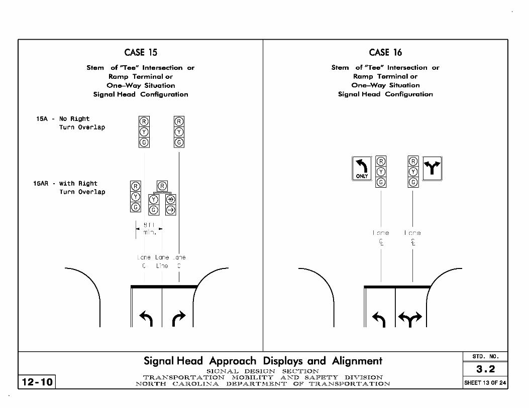
CASE 15
Stem of "Tee" Intersection or
Ramp Terminal or
One-Way Situation
Signal Head Configuration
15A - No Right Turn Overlap
15AR - with Right Turn Overlap
IR
CD © IR
CD ©
Lone Lone Lone
Il Line Il
I I I
CASE 16
Stem of tiT ee" I ntersection or
Ramp Terminal or
One-Way Situation
Signal Head Configuration
~~ ONLY IffiI
Lone Lone
Il Il
Signal Head Approach Displays and Alignment
12-101 SIGNAL DESIGN SECTION
TRANSPORTATION MOBILITY AND SAlFETY DIVISION NORTH CAROLINA DEP AR TMENT OlF TRANSPORTATION
STD. NO.
3.2 SHEET 13 OF 24
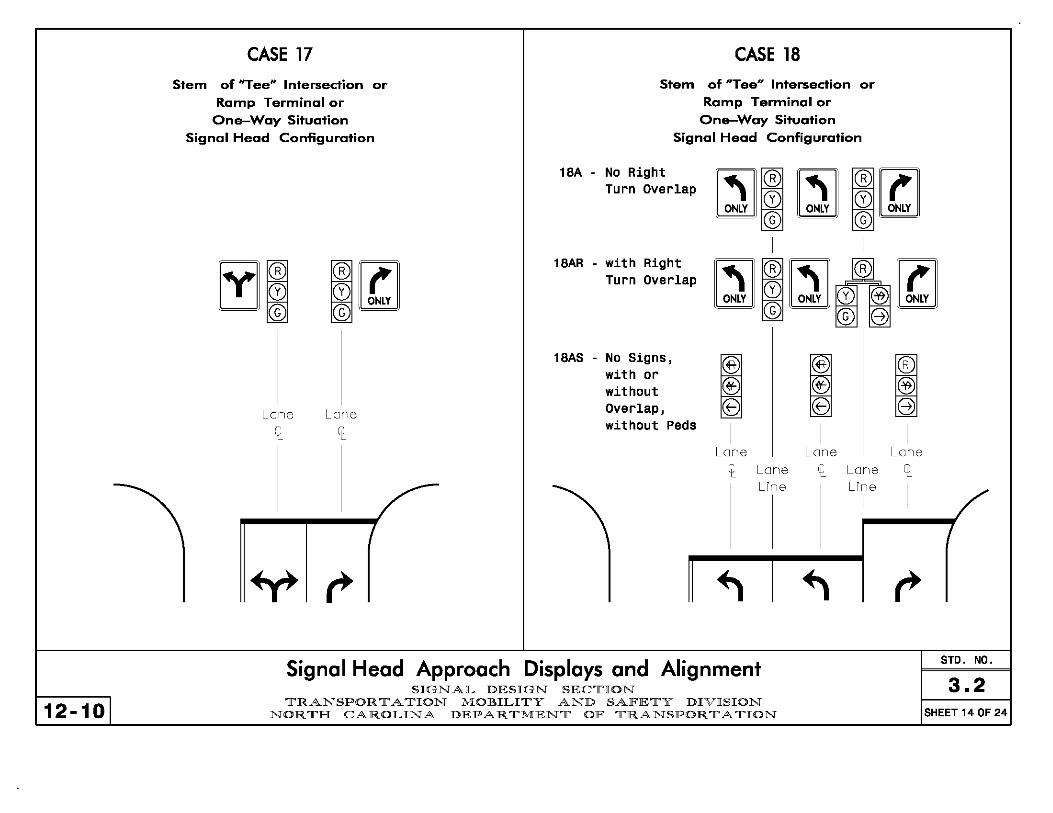
12-101
CASE 17
Stem of "Tee" Intersection or
Ramp Terminal or One-Way Situation
Signal Head Configuration
Lone Lone
CASE 18
Stem of "Tee" Intersection or Ramp Terminal or
One-Way Situation Signal Head Configuration
l8A - No Right Turn Overlap
l8AR - with Right Turn Overlap
l8AS - No Signs, with or without Overlap, without Peds
Lone Il Lone
Line
If!-@) 8
I
Lone Il Lone
Line
I
Signal Head Approach Displays and Alignment SIGNAL DESIGN SEClrION
lrRANSPOR 11' A lrION MOBILIlrY AND SAlFElrY DIVISION NORlrH CAROLINA DEPARlrMENlr OlF lrRANSPORlrAlrION
IR
@ 8)
I
Lone Il
I
STD. NO.
3.2 SHEET 14 OF 24

CASE 19
Stem of "Tee" Intersection or
Ramp Terminal or
One-Way Situation
Signal Head Configuration
19A - No Right Turn Overlap
19AR - with Right Turn Overlap, With Peds
19A5 - No Signs, with or without Overlap, No Peds
Lone
It
I
Lone LIne
I
IR
@ e
I
Lone It
I
Lone LIne
I
IR
@ e
I
Lone II
I
CASE 20
Stem of "Tee" Intersection or Ramp Terminal or
One-Way Situation
Signal Head Configuration
~~r~ight ~mR ~mR ~mR ~ Overlap, ~I 0 ~10 ~10 ~I with Signs © © ©
20A -
20AP - No Signs, with or without Overlap, with Peds
20AS - No Signs, with or without Overlap, No Peds
Lone It I
I I I
Lone Lone Lone
Line Line Line
~ § I
Lone It I
'(§) f@ ~
@ e T ~ ~
I
Lone II I
® @ fB 8 T ~ ~
I
Lone It I
Signal Head Approach Displays and Alignment SIGNAL DESIGN SEC1['ION
STD. NO.
3.2 12-101
1['RANSPOR 1[' A 1['ION MOBILI1['Y AND SAlFE1['Y DIVISION NOR 1['H CAROLINA DEPAR 1['MEN1[' OlF 1['RANSPOR 1[' A 1['ION SHEET 15 OF 24

12-101
CASE 21 CASE 22
Split Phasing Split Phasing Signal Head Configuration Signal Head Configuration
~ IR CD CD * © © * 1.~}:.1
I
Lone
Lone
Signal Head Approach Displays and Alignment SIGNAL DESIGN SEClrION
lrRANSPOR 11' A lrION MOBILIlrY AND SAlFElrY DIVISION NORlrH CAROLINA DEPARlrMENlr OlF lrRANSPORlrAlrION
IR
CD ©
Lone
I
STD. NO.
3.2 SHEET 16 OF 24

CASE 23 CASE 24
Split Phasing Split Phasing Signal Head Configuration Signal Head Configuration
23C - No Right Turn Overlap
23CR - with Right Turn Overlap
12-101
~ ~ © ~ © ~ I
Lone Lone
It It
(§5 J® '0 ~ I*© ~ ~ G©e
~£r Lone LIne
Lone It
I
Signal Head Approach Displays and Alignment SIGNAL DESIGN SECTION
TRANSPORTATION MOBILITY AND SAlFETY DIVISION NORTH CAROLINA DEP AR TMENT OlF TRANSPORTATION
Lone It
STD. NO.
3.2 SHEET 17 OF 24

12-101
CASE 25 CASE 26
Split Phasing Split Phasing Signal Head Configuration Signal Head Configuration
Lone Lone
It It
~R
CD ©
Lone Lone
Signal Head Approach Displays and Alignment SIGNAL DESIGN SECTION
TRANSPORTATION MOJIULITY AND SAF'ETY DIVISION NORTH CAROLINA DEPARTMENT OF' TRANSPORTATION
STO. NO.
3.2 SHEET 18 OF 24

CASE 27 CASE 28
Split Phasing Split Phasing Signal Head Configuration Signal Head Configuration
27C - No Right Turn Overlap
27CR - with Right Turn Overlap
12-101
® CD © 8 -=
I
Lone
~R
o ©
Lone Line Line
t I
Lone LIne
Signal Head Approach Displays and Alignment SIGNAL DESIGN SEC1['ION
1['RANSPOR 1[' A 1['ION MOBILI1['Y AND SAlFE1['Y DIVISION NOR 1['H CAROLINA DEPAR 1['MEN1[' OlF 1['RANSPOR 1[' A 1['ION
t
IR
o ©
Lone
LIne
STD. NO.
3.2 SHEET 19 OF 24
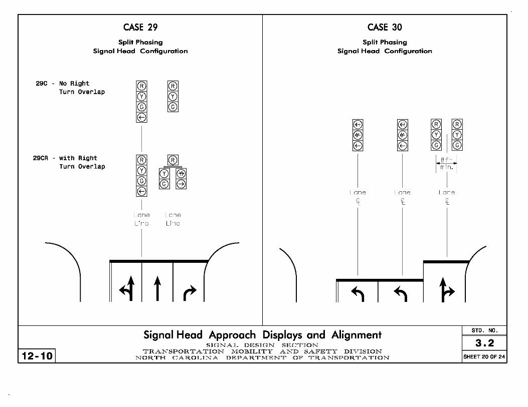
CASE 29 CASE 30
Split Phasing Split Phasing Signal Head Configuration Signal Head Configuration
29C - No Right Turn Overlap
29CR - with Right Turn Overlap
12-101
® cD © 8 =
I
~R
CD ©
Lone Lone
Line Line
4 t
Lone
I
Signal Head Approach Displays and Alignment SIGNAL DESIGN SEClrION
lrRANSPOR 11' A lrION MOBILIlrY AND SAlFElrY DIVISION NORlrH CAROLINA DEPARlrMENlr OlF lrRANSPORlrAlrION
Lone
IR ~R CDICD © ©
1'~i;o'l I
Lone
STDo NOo
3.2 SHEET 20 OF 24

CASE 31 (1 OF 2) CASE 31 (2 OF 2)
Split Phasing Split Phasing Signal Head Configuration Signal Head Configuration
31C - with Signs, No Right Turn Overlap
31CS -
12-101
without Signs, No Right Turn Overlap
Lone
Il Lone
Line
Lone Il
I
~R
CD ©
Lone Lone
Line Il
I
31CR - with Signs, with Right Turn Overlap
31CRS - without Signs, with Right Turn Overlap
Lone
Il
Signal Head Approach Displays and Alignment SIGNAL DESIGN SEC1['ION
Lone
Line
1['RANSPOR 1[' A 1['ION MOBILI1['Y AND SAlFE1['Y DIVISION NOR 1['H CAROLINA DEPAR 1['MEN1[' OlF 1['RANSPOR 1[' A 1['ION
® J@l "0 ~ ~© ~ ~ G©q ®~~
I' ~T~o 'I Lone
Line
I
STDo NOo
3.2 SHEET 21 OF 24

CASE 32
Split Phasing Signal Head Configuration
32A - with Signs
CASE 33
Split Phasing Signal Head Configuration
for Dual Right Turn Movements
33A - No Right Turn Overlap
'cID m 0 @
'''' - .. ,.,., ,.,0' r". I ® CB IR
o ©
33AR - with Right Turn Overlap No Crosswalks or Ped Heads
33ARP - with Right Turn Overlap with Crosswalks and/or Ped Heads
I @ © B ~
I 8
I
'cID I 'cID
Lone
12-101
Lone Lone
m 0 ® © e """
It Lone Lane Lone Line Line
I I It
Lone LIne
I
4 Signal Head Approach Displays and Alignment
SIGNAL DESIGN SEClrION lrRANSPOR 11' A lrION MOBILIlrY AND SAlFElrY DIVISION
NORlrH CAROLINA DEPARlrMENlr OlF lrRANSPORlrAlrION
@ $ e ~
I
Lone It
Lone LIne
I ,.
I @ 8
I
'cID @ $ e ~
I
Lone It
,. STD. NO.
3.2 SHEET 22 OF 24
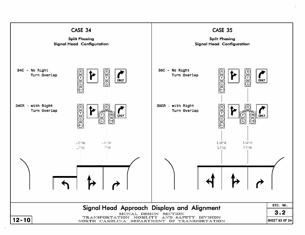
CASE 34 CASE 35
Split Phasing Split Phasing Signal Head Configuration Signal Head Configuration
34C - No Right Turn Overlap
34CR - with Right Turn Overlap
12-101
Lone Line
Lone Line
35C - No Right Turn Overlap
35CR - with Right Turn Overlap
Lone Line
Signal Head Approach Displays and Alignment SIGNAL DESIGN SEC1['ION
1['RANSPOR 1[' A 1['ION MOBILI1['Y AND SAlFE1['Y DIVISION NOR 1['H CAROLINA DEPAR 1['MEN1[' OlF 1['RANSPOR 1[' A 1['ION
Lone Line
STD. NO.
3.2 SHEET 23 OF 24

CASE 36 CASE 37
Split Phasing Split Phasing
Signal Head Configuration Signal Head Configuration
36C - No Right Turn Overlap
36CR - with Right Turn Overlap
12-101
Z§S m © B T Z§S m © B ~
I
~R
~ ©
~R
~ ©
~R
~ ©
Lone Lone Lone Line Line Line
t t
37C - No Right Turn Overlap
37CR - with Right Turn Overlap
Lone Lone
Signal Head Approach Displays and Alignment SIGNAL DESIGN SEClrION
lrRANSPOR 11' A lrION MOBILIlrY AND SAlFElrY DIVISION NORlrH CAROLINA DEPARlrMENlr OlF lrRANSPORlrAlrION
t
~R
~ ©
~R
~ ©
~R
~ ©
Lone Lone LIne Line
t STD. NO.
3.2 SHEET 24 OF 24

Typically loops are labeled according to their right-af-way phase (number) and from inside to outside (letter) beginning with the loops farthest from the stop line. A protected! permissive loop is labeled according to its protected phase.
15 protected dual lefts
04 through 07 protected I right turn 1 ~ 04 permissive tied to 051:1, ,1." left turn
~ . ~ I@ I
~m,w JU tnrtt lL! 't..
06 throughs -
@o @O
@o @O
~ ~ 01 protected/06 permissive left
( o@ O@
O@ O@
02 throu~ & .... _ through right ~
7-09 I
* Note- For some designs if the Phase 8 right turn is an overlap with Phase 1 (protected left phase of a protected/permissive move), this movement may call phase 1 directly (rather than phase B) and Loop BC should be numbered as Loop 1B.
08 permissive
~ t ,. left7T~os right turn"
08 through
Typical Numbering of Loops'Detection Zones SIGNAL DESIGN SEC1['ION
1['RANSPOR 1[' A 1['ION MOBILI1['Y AND SAlFE1['Y DIVISION NOR 1['H CAROLINA DEPAR 1['MEN1[' OlF 1['RANSPOR 1[' A 1['ION
STD. NO.
4.0 SHEET 1 OF 1

Volume Density Operation
- - - - - - - -
j - - - -
OL -- - - - - - - -
OL "V
I- D ~I l L = 6ft X 6ft (1.8m X 1.8m)
Presence loop Wired in series for TSl C~nt rolle rs
Design Speed Wired to separate detectors/channels
D for 170, TS2, and 2070 Controllers mph (km/hr) ft (m)
40 (64) 250 (75) Design Considerations: 45 (72) 300 (90) -High speed [~40 mph (64 km/hr)] 50 (80) 355 (110) -Preferred option for cost and efficiency 55 (88) 420 (130) Notes:
-Set vehicle call memory to "LOCK" -Not appropriate for use with out-of-street detection -Volume density loops can double as system detectors when wired separately.
Loop Placement for Main Street Through Movements STD. NO.
SIGNALS & GEOMETRICS SECTION 4.1.1 11-061
TRAFFIC ENGINEERING AND SAFETY SYSTEMS BRANCH NORTH CAROLINA DEPARTMENT OF TRANSPORTATION SHEET 1 OF 4

Volume Density Operation with DOEC (Delayed Call'fxtended Call)
- - - - - - - - L1 = 6ft X 6ft (1.8m X 1.8m) Presence loop
J' Wired in series for TS1 Controllers Wired to separate detectors/channels - - - -
OL1 - L2 I I for 170, TS2, and 2070 Controllers - - - - - - - - L2 = 6ft X 40ft o L1 "V L2 I I (1.8m X 12.0m)
I- ·1 1 Quadrupole loop Wired to separate
0 detectors/channels
Design Considerations: ·High speed [~40 mph (64 km/hr)] ·High volume driveways between L1 and L2 ·Single lane approach with left turns
Design Speed D L2 ·High truck traffic with steep positive grades mph (km/hr) ft (m) Delay Extend ·Out·of·street detection
sec sec ·More efficient than standard "stretch" 40 (64) 250 (75) 5.0 2.0
45 (72) 300 (90) 5.0 2.0 detection, but costlier to install and maintain
50 (80) 355 (110) 5.0 2.0 Notes: 55 (88) 420 (130) 5.0 2.0 ·00 not program "ACTUATIONS B4 ADD" (not applicable
for 2070 controllers), "SEC. PER ACTUATION" and "MAX. INITIAL"
-Delay on loops L2 must be FULL TIME delay -DO not program "Vehicle Call Memory" for phases 2 & 6 -Loops L1 can double as system detectors when wired separately
Loop Placement for Main Street Through Movements STD. NO.
SIGNALS & GEOMETRICS SECTION 4.1.1 5-05
TRAFFIC ENGINEERING AND SAFETY SYSTEMS BRANCH NORTH CAROLINA DEPARTMENT OF TRANSPORTATION SHEET 2 OF 4
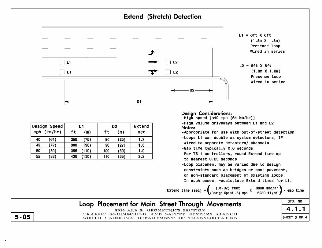
Extend (Stretch) Detection
L1 = 6ft X 6ft - - - - - - - -
(1.8m X 1.8m) Presence loop
j- Wired in series - - - -
OL1 - 0 L2 - - - - - - - - L2 = 6ft X 6ft
o Ll "V 0 L2 (1.8m X 1.8m) Presence loop
~02 J 1 Wired in series
01
Design Considerations: -High speed [~40 mph (64 km!hr) 1 -High volume driveways between Ll and L2
Design Speed Dl D2 Extend Notes: mph (km/hr) ft (m) ft (m) sec -Appropriate for use with out-of-street detection
40 (64) 250 (75) 80 (25) 1.3 -Loops L 1 can double as system detectors, IF
45 (72) 300 (90) 90 (27) 1.6 wired to separate detectors! channels
50 (80) 355 (110) 100 (30) 1.9 -Gap time typically 2.0 seconds
55 (88) 420 ( 130) 110 (35) 2.2 -For TS-l controllers, round Extend time up to nearest 0.25 seconds
-Loop placement may be varied due to design constraints such as bridges or poor pavement, or non-standard placement of existing loops. In such cases, recalculate Extend times for Ll.
. _ ( (01-02) feet Extend tIme (sec) - (Design Speed .5) mph X
3600 sec/hr) . 5280 ft/mi
Gap time
Loop Placement for Main Street Through Movements STD. NO.
SIGNALS & GEOMETRICS SECTION 4.1.1 5-05 I TRAFFIC ENGINEERING AND SAFETY SYSTEMS BRANCH
NORTH CAROLINA DEPARTMENT OF TRANSPORTATION SHEET 3 OF 4

5-05 I
- - - -
j - - - -..... 0 L - - - -
"V 0 L
1--"" -~ (20m)
L = 6ft X 6ft (1.8m X 1.8m) Presence loop, wired in series
Design Considerations: -Low speed [~35 mph (56 km/hr)] -Gap time typically 3.0 seconds
Low Speed Detection
l
- - - -
j - - - -..... L I - - - -
"V L I
L = 6ft X 40ft (1.8m X 12.0m) Quadrupole loop, wired to separate detectors/channels
Design Considerations: -Low speed [~35 mph (56 km/hr)] -Gap time typically 0-2 seconds
I
I
-Preferred option -Appropriate for use with soft recall
Loop Placement for Main Street Through Movements SIGNALS & GEOMETRICS SECTION
TRAFFIC ENGINEERING AND SAFETY SYSTEMS BRANCH NORTH CAROLINA DEPARTMENT OF TRANSPORTATION
l
STD. NO.
4.1.1 SHEET 4 OF 4

Presence Detector
- - - - - - - -
j LI 1 -- - - - - - - -
"V
L = 6ft X 40ft (1.8m X 12.0m) Quadrupole Notes: l
or, if longer detection area is needed: -Loops may not be required for all 6ft X 50ft (1.8m X 15.0m) Quadrupole main street permissive turns
or -Option to use 6ft X 6ft (1.8m X 1.8m) loop 6ft X 60ft (1.8m X 18.0m) Quadrupole to wire in series with 70' through loops.
Loop Type Delay time Full Time Delay Left Turn Loop on Main Street o sec N/A with Low Speed or Stretch Detection
Left Turn Loop on Main Street 3-5 sec Yes with Volume Density Detection
Left Turn Loop on Side Street 2-3 sec if "clipping" prevention No is desired; 0 sec otherwise
Loop Placement for Permissive Left Turns STD. NO.
SIGNALS & GEOMETRICS SECTION 4.1.2 5-05 I TRAFFIC ENGINEERING AND SAFETY SYSTEMS BRANCH
NORTH CAROLINA DEPARTMENT OF TRANSPORTATION SHEET 1 OF 1

Presence Loop with 2 Channel Detector
- - - - - - L = 6ft X 40ft (1.8m X 12.0m) Quadrupole loop
or, if longer detection area is needed: j L [ 1 6ft X 50ft (1.8m X 15.0m) Quadrupole loop
- - - -..... or - - - - - - 6ft X 60ft (1.8m X 18.0m) Quadrupole loop
"V
Design Considerations: ~ -Facilitates upgrade to fully protected Note: or downgrade from fully protected -Calling/extending the permissive phase may
-Calls up arrow when 1 or 2 cars not be required for main street loops waiting to turn -Gap time typically 1-3 seconds
-Consider queue loop (Std. No. 4.1.3:2) for light left turn traffic or for light opposing through traffic
Detector Phase Delay Time Full Time Delay Loop Type Channel Left Turn Loop on Main Street 1 Protected Phase 10-30 sec No
with Low Speed or Stretch Detection 2 Permissive Phase Osee N/A Left Turn Loop on Main Street 1 Protected Phase 10-30 sec No
with Volume Density Detection 2 Permissive Phase 3-5 sec Yes 1 Protected Phase 10-30 sec No
Left Turn Loop on Side Street 2 Permissive Phase 2-3 sec if "clipping" prevention No
is desired; 0 sec otherwise
Loop Placement for ProtectedtPermissive Left Turns STD. NO.
SIGNALS & GEOMETRICS SECTION 4.1.3 5-05 I TRAFFIC ENGINEERING AND SAFETY SYSTEMS BRANCH
NORTH CAROLINA DEPARTMENT OF TRANSPORTATION SHEET 1 OF 2

Queue Detector Loop
L1 = 6ft X 15ft (1.8m X 4.5m) Presence loop (Queue
- - - - - - - - detector) with Call delay
j L1 c=J c:-: - - - __ I L2 = 6ft X 40ft L2
~------' (1.8m X 12.0m) - - - - - - - -- Quadrupole loop - - - - - - - -
"V
1 Notes:
I~- ~ ·L2 is optional when permitted
50 ft phase has minimum recall
Design Consideration: ( 15m) ·L 1 min green typically 8 seconds ·L 1 gap time typically 2·4 seconds
-Calls up arrow when 3 or more -L2 time typically 1-3 seconds cars waiting to turn
gap
-Consider for side street left turns
Loop Type Phase Delay Time Full Delay Time
L 1 : Queue Detector Protected Phase 5-15 sec No
L2: Left Turn Loop on Main Street Permissive Phase Osee N/A with Low Speed or Stretch Detection L2: Left Turn Loop on Main Street Permissive Phase 3-5 sec Yes with Volume Density Detection
L2: Left Turn LOOp on Side Street Permissive Phase 2-3 sec if "clipping" prevention No is desired; 0 sec otherwise
Loop Placement for ProtectedlPermissive Left Turns STD. NO.
SIGNALS & GEOMETRICS SECTION 4.1.3 5-05 I TRAFFIC ENGINEERING AND SAFETY SYSTEMS BRANCH
NORTH CAROLINA DEPARTMENT OF TRANSPORTATION SHEET 2 OF 2

5-05 I
L = 6ft X 40ft (1.8m X 12.0m) Quadrupole
or, if longer detection area is needed:
6ft X 50ft (1.8m X 15.0m) Quadrupole or
6ft X 60ft (1.8m X 18.0m) Quadrupole
Presence Detector
-
-
- - -
j LI 1 -- - -
"V
l Notes: -Gap time typically 1-3 seconds -A short (2 or 3 sec) call delay may be used if turning vehicles are able to "clip" loop L
-If call delay is used, do not program full time delay
Loop Placement for Protected Left Turns SIGNALS & GEOMETRICS SECTION
TRAFFIC ENGINEERING AND SAFETY SYSTEMS BRANCH NORTH CAROLINA DEPARTMENT OF TRANSPORTATION
STD. NO.
4.1.4 SHEET 1 OF 1

5-05 I
r Typical Presence Detection
L = 6ft X 40ft (1.8m X 12.0m) Quadrupole loop Wired to separate detectors/channels
or, if longer detection area is needed:
6ft X 50ft (1.8m X 15.0m) Quadrupole or
6ft X 60ft (1.8m X 18.0m) Quadrupole
Notes: -Consider delay (NOT full time) if through lane is shared with a right-turn move, except where right turn on red is prohibited
-Gap time typically 1-3 seconds -Consider higher gap time or longer detection area under the following circumstances:
-Steep positive approach grade -High truck volumes
Loop Placement for Side Street Through Movements SIGNALS & GEOMETRICS SECTION
TRAFFIC ENGINEERING AND SAFETY SYSTEMS BRANCH NORTH CAROLINA DEPARTMENT OF TRANSPORTATION
STD. NO.
4.1.5 SHEET 1 OF 3

5-05 I
I
~
I
t ~ I
L 1 I L1
00
(
D
Volume Density Operation with DOEC (Delayed Call-fxtended Call
Ll = 6ft x 6ft (1.8m X 1.8m) Presence loop Wired in series for TSl Controllers Wired to separate detectors/channels
for 170, TS2, and 2070 Controllers
L2 = 6ft X 40ft (1.8m X 12.0) Quadrupole loop Wired to separate detectors/channels
Design Speed mph (km/hr)
40 (64)
45 (72) 50 (80) 55 (88)
Notes:
ft
250 300
355
420
D (m)
(75)
(90) (110) ( 130)
Delay sec 5.0 5.0 5.0 5.0
L2
Extend sec 2.0 2.0 2.0 2.0
-Do not program "ACTUATIONS B4 ADD" (not applicable for 2070 controllers), "SEC. PER ACTUATION" and "MAX. INITIAL."
-Delay on loops L2 must be FULL TIME delay -Do not program "Vehicle Call Memory" for phases 4 & 8.
-Loops Ll should be programmed for "EXTENSION" but NOT "CALLING."
Design Considerations:
-Cross intersection AND -High speed [~40 mph (64 km/hr)] AND -Good horizontal and vertical alignment -In some cases can provide better efficiency than "stretch" detection
-For TS2 controllers, loops Ll must be programmed with 100 second delay (INHIBIT DELAY DURING GREEN = YES) to ensure that the loop acts to extend the phase only.
-Loops Ll can double as system detectors if wired separately.
Loop Placement for Side Street Through Movements STD. NO.
4.1.5 SIGNAL DESIGN SEC1['ION 1['RANSPOR 1[' A 1['ION MOBILI1['Y AND SAlFE1['Y DIVISION
NOR 1['H CAROLINA DEPAR 1['MEN1[' OlF 1['RANSPOR 1[' A 1['ION SHEET 2 OF 3

'\ f" Extend (Stretch) Detection
L1 = 6ft X 6ft (1.8m X 1.8m) L2 = 6ft (1.8m) X 02 Quadrupole loop Presence loop, Wired in series Wired to separate detectors/channels
I I I Design Speed 01 02 Gap Time L1
02 mph (km/hr) ft (m) ft (m) Extend sec sec
40 (64) 250 (75) 40 (12) 2.0 2.1
I I I
60 (18) 1.0 2.7 I 40 (12) 2.0 2.4 L2 L2 45 (72) 300 (90) 60 (18) 1.0 3.1
50 (80) 355 (110) 40 ( 12) 2.0 2.8
I I I 60 ( 18) 1.0 3.5 40 ( 12) 2.0 3.2
t ~ 55 (88) 420 (130) 60 ( 18) 3.9 ~ 1.0
I I I
D1 Design Considerations: -Cross intersection AND -High speed [~40 mph (64 km/hr)] AND -Good horizontal and vertical alignment
I I I Notes:
-Loops L1 should be programmed for -For TS2 controllers, in addition to "EXTENSION" but NOT "CALLING." appropriate extend time, loops L1 must
-For TS-1 controllers, round Extend be programmed with 100 second delay
I I I time up to nearest 0.25 seconds. (INHIBIT DELAY DURING GREEN = YES)
-Loop placement may be varied due to to ensure that the loop acts to only design constraints such as bridges or extend the phase. poor pavement, or non-standard -Loops L1 can double as system
I I L1 I L 1 placement of existing loops. In such detectors, if wired separately.
o 0 cases, recalculate Extend times for L1 (See Std. 4.1.1:3).
Loop Placement for Side Street Through Movements STD. NO.
SIGNAL DESIGN SEClrION 4.1.5 8-10 I lrRANSPOR 11' A lrION MOBILIlrY AND SAlFElrY DIVISION
NORlrH CAROLINA DEPARlrMENlr OlF lrRANSPOR 11' A lrION SHEET 3 OF 3

5-05 I
Standard Turn
L1
I I I
I I
... t ,. I I
Wide Radius Turn
L1 L2 ~
r
Typical Detector Layouts
L1 = 6ft X 40ft (1.8m X 12.0m) Quadrupole loop L2 = 6ft X 6ft (1.8m X 1.8m) [Minimum] Presence loop
Wired to separate detector/channel L3 = 6ft X 30ft (1.8m X 9.0m) Quadrupole loop
Notes: -Call delay appropriate for right turn loops unless right turn on red is prohibited.
-Suggestions for delay: -Exclusive right turn lane: 15 sec -Right turn lane shared with through or through/ left movement: 10 sec or greater
-Do not program full time delay.
Channelized Turn
~L3h -!II I
Delete detection for yield condition
Loop Placement for Side Street Right Turns SIGNALS & GEOMETRICS SECTION
TRAFFIC ENGINEERING AND SAFETY SYSTEMS BRANCH NORTH CAROLINA DEPARTMENT OF TRANSPORTATION
STD. NO.
4.1.6 SHEET 1 OF 1

5-05
Locate loop slightly behind leading
.dg. of .top li"'~
________ I_n_d_u_ct_1_.v_e __ L_OO_P ________ ~J
Note: LOOp may be located in advance of stop line when stop line is greater than 15' (4.5m) from edge of intersecting roadway; or, when loop detects a permissive or protected/permissive left turn.
Placement of Presence Loops SIGNALS & GEOMETRICS SECTION
TRAFFIC ENGINEERING AND SAFETY SYSTEMS BRANCH NORTH CAROLINA DEPARTMENT OF TRANSPORTATION
STD. NO.
4.1.7 SHEET 1 OF 1

Amount of Inductance, Loop Dimension Inductance Sealant Sawcut ft Turns Loop Wire
gal * ft Loop Wire, Sealant and uh ft (m) (m) (liter) (m) Sawcut for Inductive Loops
3 72 72 (22)
6 X 6 4 120 96 (30) 0.8 24 Calculate additional loop wire or sawcut for (1.8 X 1.8) 5 180 120 (37) (3) (7) loop wire tail section by measuring length
of tail section from loop to edge of pavement. 6 252 144 (44)
OR 2 63 84 (26)
6 X 15 3 126 126 (39) 1.3 42 I ENGL ISH I L (ft) = 6+(N·1)12
(1.8 X 4.5) (5 ) ( 13) 4 210 168 (52) I METR IC I L (m) = 1.8+(N-1)3.6
6 X 25 2-4-2 218 224 2.7 87 (1.8 X 7.5) (69) (10) (27) Where: L = Length of loop wire or sawcut
N = Number of lanes crossed by
6 X 30 264 3.1 102 tail section
(1.8 X 9.0) 2-4-2 258 (81 ) ( 12) (31 ) To calculate additional sealant
6 X 40 2-4-2 344 4.0 132 for loop wire tail section: (1.8 X 12.0) 338 (105 ) ( 16) (41 )
I ENGL ISH I s (gal) = L (ft) I 33 6 X 50 2-4-2 418 424 5.0 162
(1.8 X 15.0) (130) ( 19) (50) I METR IC I S (liters) = L (m) I 2.6
6 X 60 2-4-2 498 504 5.9 192 Where: S = Amount of sealant (1.8 X 18.0) (154) (23) (59) L = Length of sawcut required for
tail section * Amount of sealant is rounded up to nearest tenth of a gallon or liter
Loop Wire and Lead-In Calculations STD. NO.
SIGNALS & GEOMETRICS SECTION 4.2 5-05 I
TRAFFIC ENGINEERING AND SAFETY SYSTEMS BRANCH NORTH CAROLINA DEPARTMENT OF TRANSPORTATION SHEET 1 OF 2
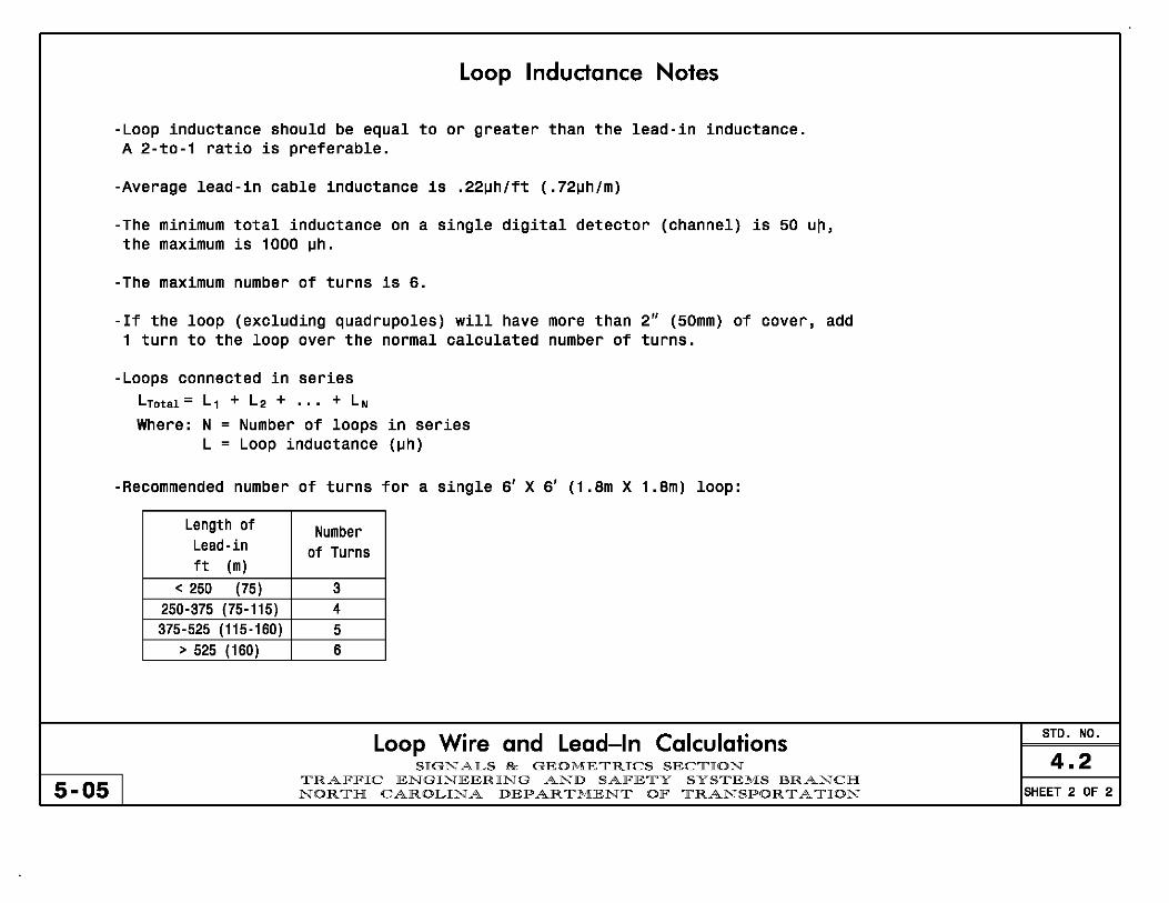
Loop Inductance Notes
-LOOp inductance should be equal to or greater than the lead-in inductance. A 2-to-1 ratio is preferable.
-Average lead-in cable inductance is .22~h/ft (.72~h/m)
-The minimum total inductance on a single digital detector (channel) is 50 u~,
the maximum is 1000 ~h.
-The maximum number of turns is 6.
-If the loop (excluding quadrupoles) will have more than 2" (50mm) of cover, add 1 turn to the loop over the normal calculated number of turns.
-Loops connected in series LTotal = L1 + L2 + ... + LN Where: N = Number of loops in series
L = Loop inductance (~h)
-Recommended number of turns for a single 6' X 6' (1.8m X 1.8m) loop:
5-05 I
Length of Lead-in ft (m)
< 250 (75) 250-375 (75-115) 375-525 (115·160)
> 525 (160)
Number of Turns
3 4
5 6
Loop Wire and Lead-In Calculations SIGNALS & GEOMETRICS SECTION
TRAFFIC ENGINEERING AND SAFETY SYSTEMS BRANCH NORTH CAROLINA DEPARTMENT OF TRANSPORTATION
STD. NO.
4.2 SHEET 2 OF 2
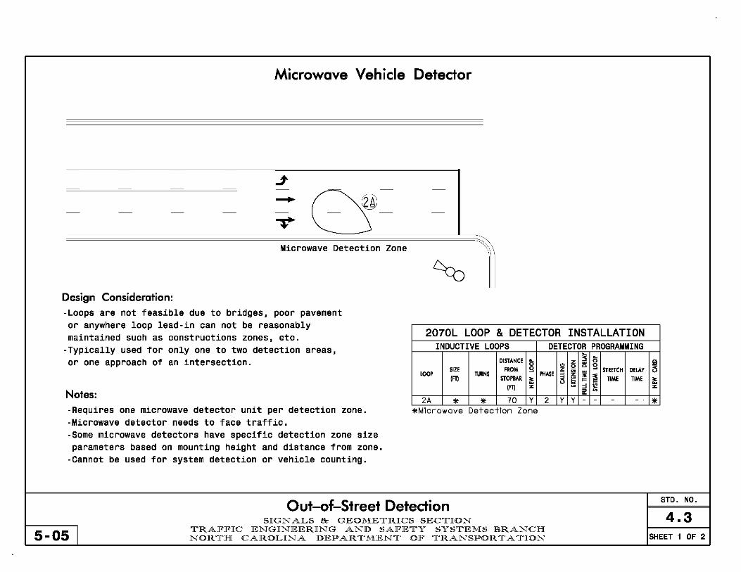
Microwave Vehicle Detector
- - - - - - - -
j -
cs= --- - - - - -
"V Microwave Detection Zone I ~
Design Consideration: -LOOpS are not feasible due to bridges, poor pavement or anywhere loop lead-in can not be reasonably
2070L LOOP & DETECTOR INSTALLATION maintained such as constructions zones, etc. -Typically used for only one to two detection areas, INDUCTIVE LOOPS DETECTOR PROGRAMMING
or one approach of an intersection. DISTANCE 1; z ;s 1; Ii! '" 0 ~ g
SIZE FROM g z ~ STRETCH DELAY <5 LOOP TURNS PHASE 5 ~ ~ IFn STOPBAR ~ ~ TIME TIME ~
1FT} z " };i z
Notes: ii! 2A * * 70 Y 2 Y Y - * -Requires one microwave detector unit per detection zone. *Mlcrowave Detection Zone
-Microwave detector needs to face traffic. -Some microwave detectors have specific detection zone size parameters based on mounting height and distance from zone.
-Cannot be used for system detection or vehicle counting.
Out-of-Street Detection STD. NO.
SIGNALS & GEOMETRICS SECTION 4.3 5-05 I
TRAFFIC ENGINEERING AND SAFETY SYSTEMS BRANCH NORTH CAROLINA DEPARTMENT OF TRANSPORTATION SHEET 1 OF 2

Video Detection Systems (Loop Emulator)
j I I I I
/ L _________________ //
j~ ~~j( Video DetectIon Zone
@O ------------------ --, ""==construction Area
Design Consideration: -Loops are not feasible due to bridges, poor pavement, 2070L LOOP & DETECTOR INSTALLATION or anywhere loop lead-in can not be reasonably INDUCTIVE LOOPS DETECTOR PROGRAMMING
maintained such as constructions zones, etc. DISTA.NCE 1; z ~ 1; !:! .. :il c 0
SIZE FIOM 9 z
! --' STRETCH DELAY u
-Flexibility is desired in detection areas due to traffic Loor IF~
ruINS STOPBAIt.
PHASE 5 ~ ~ ~ TIME TIME ~ shifts associated with constuction phasing IFYI z :I ~ z
" -All other detection options have been exhausted. 2A 6X6 * 70 * 2 Y Y - * 5A 6X40 * 0 * 5 Y Y - * *Video Detection Zone Notes:
-Cannot be used for vehicle counting. -Cannot be used for system detection.
Out-of-Street Detection STD. NO.
S I GNAL S & GEOME T R ICS SECT ION 4.3 5-05 I
T RAF F I C E NGI NEER I NG AND SAF E T Y SYSTEMS B RANCIH NORT H CAROL INA D E PARTME NT OF TRANSPORT A T ION SHEET 2 OF 2

NOTES WHEN TO USE
Drawing Notes Std. No. Signal Design Section 5.0 Transportation Mobility and Safety Division
12-10 North Carolina Department of Transportation Sheet 1 of 4
L 01 Refer to "Roadway Standard Drawings NCDOT" dated July 2006 and "Standard Specifications for Roads and Structures" dated July 2006.
L 03 Refer to "Roadway Standard Drawings NCDOT" dated July 2006, "Standard Specifications for Roads and Structures" dated July 2006, and all applicable sections of the latest version of the generic Project Special Provisions. The PSP can be accessed at the following website:
http://www.ncdot.org/doh/preconstruct/traffic/itss/
L 04 Do not program signal for late night flashing operation unless otherwise directed by the Engineer.
L 05 This location contains railroad preemption phasing. Do not program signal for late night flashing operation.
L 10 Omit phase 1 during phase 2 on.
L 11 Program phase 1 as protected/permissive.
L 12 Omit phase 5 during phase 6 on.
L 13 Program phase 5 as protected/permissive.
L 14 Omit phase 3 during phase 4 on.
L 15 Program phase 3 as protected/permissive.
L 16 Omit phase 7 during phase 8 on.
L 17 Program phase 7 as protected/permissive.
L 18 Wire cabinet to allow the controller to clear from phase # to phase # by progressing through phase # (see Electrical Details for wiring).
L 19 Program controller to clear from phase # to phase # by progressing through phase # (see Electrical Details).
L 20 Enable Backup Protect for phase # to allow the controller to clear from phase # to phase # by progressing through an all red display.
L 21 Disable Backup Protect for phase #.
H 01 All Plans except Developer Plans
H 03 Developer Plans
H 04 For locations without railroad preemption
H 05 For locations with railroad preemption
H 10 Phase omit note for TS1,TS2, and 2070 operation
H 11 Phase omit note for 170 operation
H 12 Phase omit note for TS1,TS2, and 2070 operation
H 13 Phase omit note for 170 operation
H 14 Phase omit note for TS1,TS2, and 2070 operation
H 15 Phase omit note for 170 operation
H 16 Phase omit note for TS1,TS2, and 2070 operation
H 17 Phase omit note for 170 operation
H 18 Additional note for omit situations for TS1 operation
H 19 Additional note for omit situations for TS2, 2070, and 170
operation
H 20 Alternate to Phase Omits in 2070s. Used with Red Revert.
H 21 Use for FYA plans with existing 2070 cabinets where
backup protection is no longer needed.

NOTES WHEN TO USE
Drawing Notes Std. No. Signal Design Section 5.0 Transportation Mobility and Safety Division
12-10 North Carolina Department of Transportation Sheet 2 of 4
L 22 Phase 1 and/or phase 5 may be lagged.
L 23 Phase 3 and/or phase 7 may be lagged.
L 24 The order of phase 3 and phase 4 may be reversed.
L 25 Program phase 4 and phase 8 for dual entry.
L 30 Relocate existing signal heads numbered #.
L 31 Reposition existing signal heads numbered #.
L 32 Install backplates for signal heads numbered #.
L 33 Tether signal heads numbered #.
L 40 Run all lead-in cable overhead on existing utility poles where possible.
L 41 Abandon existing loops #.
L 42 Use controller input delay for phase #. Override channel # call delay during peak hours.
L 43 Set all detector units to presence mode.
L 44 In the event of loop replacement, refer to the current ITS and Signals Design Manual and submit a Plan of Record to the Signal Design Section.
L 50 Locate new cabinet so as not to obstruct sight distance of vehicles turning right on red.
L 51 The cabinet should be designed to include an Auxiliary Output File for future use.
L 52 Program all timing information into phase banks 1, 2, and 3 unless otherwise noted.
L 53 Set phase bank 3 maximum limit to 250 seconds for phases used.
L 60 Omit "WALK" and flashing "DON'T WALK" with no pedestrian calls.
H 21 Use for exclusive left turns and Flashing Yellow Arrows
H 22 Use for exclusive left turns and Flashing Yellow Arrows
H 23 Use for split side streets
H 24 For use with TS-1 or TS-2 equipment
H 30 Use when head is moved to new span
H 31 Use when head is "slid" on same span
H 32 As needed
H 33 As needed
H 40 Urban projects with many driveways
H 41 As needed, usually by contracts
H 42 Add this note for variation on protected-permissive design.
H 43 All Plans
H 44 Use when not replacing “old style” loops
H 50 All plans with new cabinets
H 51 Use on plans with new 2070 cabinets and no FYA
H 52 Standard with 170 operation
H 52 Signal system plans with 170s
H 60 Use for pedestrian-activated signals
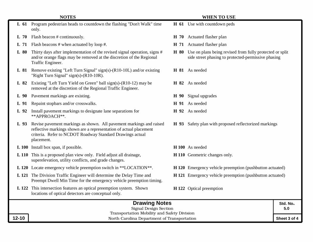
NOTES WHEN TO USE
Drawing Notes Std. No. Signal Design Section 5.0 Transportation Mobility and Safety Division
12-10 North Carolina Department of Transportation Sheet 3 of 4
L 61 Program pedestrian heads to countdown the flashing "Don't Walk" time only.
L 70 Flash beacon # continuously.
L 71 Flash beacons # when actuated by loop #.
L 80 Thirty days after implementation of the revised signal operation, signs # and/or orange flags may be removed at the discretion of the Regional Traffic Engineer.
L 81 Remove existing "Left Turn Signal" sign(s)-(R10-10L) and/or existing "Right Turn Signal" sign(s)-(R10-10R).
L 82 Existing "Left Turn Yield on Green" ball sign(s)-(R10-12) may be removed at the discretion of the Regional Traffic Engineer.
L 90 Pavement markings are existing.
L 91 Repaint stopbars and/or crosswalks.
L 92 Install pavement markings to designate lane separations for **APPROACH**.
L 93 Revise pavement markings as shown. All pavement markings and raised reflective markings shown are a representation of actual placement criteria. Refer to NCDOT Roadway Standard Drawings actual placement.
L 100 Install box span, if possible.
L 110 This is a proposed plan view only. Field adjust all drainage, superelevation, utility conflicts, and grade changes.
L 120 Locate emergency vehicle preemption switch in **LOCATION**.
L 121 The Division Traffic Engineer will determine the Delay Time and Preempt Dwell Min Time for the emergency vehicle preemption timing.
L 122 This intersection features an optical preemption system. Shown locations of optical detectors are conceptual only.
H 61 Use with countdown peds
H 70 Actuated flasher plan
H 71 Actuated flasher plan
H 80 Use on plans being revised from fully protected or split side street phasing to protected-permissive phasing
H 81 As needed
H 82 As needed
H 90 Signal upgrades
H 91 As needed
H 92 As needed
H 93 Safety plan with proposed reflectorized markings
H 100 As needed
H 110 Geometric changes only.
H 120 Emergency vehicle preemption (pushbutton actuated)
H 121 Emergency vehicle preemption (pushbutton actuated)
H 122 Optical preemption

NOTES WHEN TO USE
Drawing Notes Std. No. Signal Design Section 5.0 Transportation Mobility and Safety Division
12-10 North Carolina Department of Transportation Sheet 4 of 4
L 123 Program signal heads numbered # to clear to all red before going into
preempt.
L 124 Ensure flashing operation does not alter operation of blankout signs.
L 125 Clear signal heads numbered # from flashing 8" yellow to steady 12" yellow during interval 1 and steady red during interval 2.
L 126 Program start vehicle call OFF for phase #.
L 127 Program parent phases for Overlap “P” for all phases used in normal operation.
L 128 Upon completion of Railroad (or Emergency Vehicle) Preemption, controller returns to normal operation based on vehicle demand.
L 129 The Division Traffic Engineer will determine the hours of use for each phasing plan.
L 131 These loops serve as queue backup detectors. After # seconds of constant actuation, the detector unit places a call to the controller to preempt normal operation to clear out the storage lanes.
L 132 Existing Yellow Change Interval for phase # may be decreased by # seconds per week until the required value is reached.
L 133 Maximum times shown in timing chart are for free-run operation only. Coordinated signal system timing values supersede these values.
L 134 Closed loop system data: Intersection Number #, Local telemetry address number #, Channel number #.
L 135 Closed loop system data: Master Asset #, Controller Asset #.
H 123 Use in place of dummy phase for emergency vehicle preemption
H 124 Standard with RR preemption with blank-out signs
H 125 RR preemption plans with advance flashing heads (for non-standard clearance)
H 126 RR preemption plans with preempt phase that does not have corresponding regular phase (170 controller)
H 127 Most signal plans with railroad preemption that have a Track Clearance phase.
H 128 RR or EV Preemption plan when an exit phase (first normal phase served after preemption) is not or cannot be designated
H 129 Flashing Yellow Arrow plans designed with multiple or time of day phasing options.
H 131 Backup queue detectors
H 132 Major adjustments to clearance times
H 133 Standard with coordination
H 134 Closed loop signal system plans
H 135 2070 Closed loop signal system plans

OASIS 2070L LOOP & DETECTOR INSTALLATION CHART INDUCTIVE LOOPS DETECTOR PROGRAMMING
~ ~
DISTANCE ~ z 0 c 0 ~
C) 0 c 0 "" SIZE FROM 0 z in STRETCH DELAY ~ j
LOOP TURNS ~
PHASE ::::; ~
(FT) ~ z :::e :::e STOPBAR ~ -< ~ >= TIME TIME ~ ~ ~ u I< >- ~
(FT) z ~ ~ '" z ~ >-::::> '" "-
loops { 2M1 6X6 420 5 Y 2 Y Y - - - y y
Volume density loops combined w'system 2i1'S2 6X6 420 5 Y 2 Y Y - - - y y
Queue Detector { 3A 6X15 50 3 Y 3 Y Y - - 15 - Y Oasis 2070L BA 6X40 +5 2-4-2 Y 8 Y Y - - - - y Controller
Volume Density with DOEC for sidestreet { 4A 6X6 300 5 Y 4 - Y - - - - y
4B 6X40 0 2-4-2 Y 4 Y Y Y 2.0 5 - Y
Left turn loop calling 2 phases 5 y Y - - 15 - Y 5A 6X60 0 2-4-2 Y
(with volume density on phase 2) 2 Y Y Y - 3 - Y
Stretch loops { 6A,6B 6X6 300 EXISTING - 6 Y Y - 1.6 - - y
6C,6D 6X6 90 EXISTING - 6 Y Y - - - - y
System Loop S3 6X6 +120 4 Y - - - - - - y y
Detector Programming Attributes
Calling - Select to place call during red. Selecting this Full Time Delay - Select to delay during red, yellow, attribute is similar to selecting ALL for NEMA's "Place and green. If not selected, controller will time delay Call During Phase." (Usually selected) during red and yellow only. Selecting this attribute
Extension - Select to extend the green time. Gap resets after is equivalent to selecting NO for NEMA's "Inhibit
each call. Must be selected whenever Vehicle Extension Time Delay During Green." (Usually not selected)
is entered in the timing chart. (Usually selected) Stretch Time - Enter times in intervals of .1 second
Loop Chart Typicals STD. NO.
5.1 SIGNAL DESIGN SECTION
7-09 I TRANSPORTATION MOBILITY AND SAFETY DIVISION NORTH CAROLINA DEPARTMENT OF TRANSPORTATION SHEET 1 OF 5
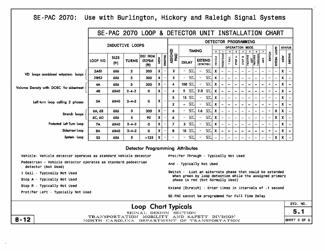
SE-PAC 2070: Use with Burlington, Hickory and Raleigh Signal Systems
SE-PAC 2070 LOOP & DETECTOR UNIT INSTALLATION CHART DETECTOR PROGRAMMING
INDUCTIVE LOOPS OPERATION MODE II! STATUS C TIMING , , , • , • , 0 ~ ,
:J: 9 z~ z g " SIZE DISI. FROM " tH « < - :; :; ~
z ~ z u ~ :< L :s t:::s 0 ~ ~ 5i LOOP NO. TURNS STOPBAR ~ ~- EXTEND iii ~ z z
(ft) z DELAY ~ u 0 o ~o « ~ iii (ft) (STRETCH) ~ - ~ ~ ~ ~
> L L
loops { 2M1 6X6 5 300 X - 2 - SEC. - SEC. x - - - - - - - - - x -
VD loops combined ~tem SEC. SEC. 2&52 6X6 5 300 X - 2 - - X - - - - - - - - - X -
Volume Density with DO'EC for sidestreet { 4A 6X6 5 300 X - 4 100 SEC. - SEC. X - - - - - - - ~ - X -4B 6X40 2-.4-2 0 X - 4 5 SEC. 2.0 SEC. X - - - - - - - - - X -
5 15 SEC. - SEC. X - - - - - - - - - X -
Left tum loop calling 2 phases 5A 6X40 2-.4-2 0 X -2 - SEC. - SEC. X - - - - - - ~ - - X -
Stretch loops { 6A; 6B 6X6 5 300 X - 6 - SEC. 1.6 SEC. X - - - - - - - - X X -
6C;6D 6X6 5 90 X - 6 - SEC. - SEC. X - - - - - - - - X X -
Protected left Tum Loop 7A 6X40 2-4-2 0 X - 7 3 SEC. - SEC. X - - - - - - ~ ~ - X -Sidestreet Loop 8A 6X40 2-4-2 0 X - 8 10 SEC. - SEC. X - - - - - - - ~ - X -
System Loop 53 6X6 5 +125 X - - - SEC. - SEC. - - - - - - - - - X X -
Detector Programming Attributes
Vehicle- Vehicle detector operates as standard vehicle detector Prot/Per Through - Typically Not Used
Pedestrian - Vehicle detector operates as standard pedestrian And - Typically Not Used detector (Not Used)
1 Call - Typically Not Used Switch - List an alternate phase that could be extended when green by loop detection while the assigned primary
Stop A - Typically Not Used phase is red (Not Normally Used) Stop B - Typically Not Used Extend (Stretch) - Enter times in intervals of .1 second Prot/Per Left - Typcially Not Used
SE-PAC cannot be programmed for Full Time Delay
Loop Chart Typicals STD. NO.
S .1 SIGNAL DESIGN SEClrION
8-12 I lrRANSPOR 11' A lrION MOllULIlrY AND SAlFElrY DIVISION NORlrH CAROLINA DEPARlrMENlr OF lrRANSPOR 11' A lrION SHEET 2 OF 5

NAZTEC 2070: Use with Greensboro Signal System
LOOP & DETECTOR UNIT INSTALLATION CHART NAZTEC APOGEE SOFTWARE 2070 CONTROLLER
INDUCTIVE LOOPS DETECTOR PROGRAMMING
DISTANCE ,..: ~ ~ z 0 c 0 '" 0 ~ g '" SIZE FROM g SWITCH DELAY STRETCH z in i:I LOOP TURNS PHASE :::; z c ! ~ (Fn STOPBAR ~ (PHASE) TIME TIME i:I
w w ~
~ c ~ w C w (Fn z < ~ z
PIP Left tum loop calling 2 phases lA 6)(40 0 2-4-2 X 1 6 15 - X X - - X
VD loop combined w1iys1em loop { 2Ml 6X6 300 5 X 2 - - - X X X X X
2852 6X6 300 5 X 2 - - - X X X X X 2070 Controller
Stretch Detection for sidestreet { 4A 6X6 300 5 X 4 - - 3,4 - X - - X
w'Naztec Apogee Software
48 6)(40 0 2-4-2 X 4 - 10 - X X - - X
PIP Left tum loop calling 2 phases 5A 6)(40 0 2-4-2 X 5 2 15 - X X - - X
Stretch loops { 6A; 68 6X6 300 5 X 6 - - 1,6 X X - - X
6Ci6D 6X6 'Xl 4 X 6 - - - X X - - X
Protected left tum phase loop 7A 6)(40 0 2-4-2 X 7 - 3 - X X - - X
Sidestreet loop 8A 6)(40 0 2-4-2 X 8 - 10 - X X - - X
System Loop S3 6X6 +125 5 X - - - - - - - X X
Detector Programming Attributes
Switch (Phase) - Typically used for protectedlpermitted left Extension - Select to extend the green time. Gap resets after turns to call and extend the (primary) protected phase after each call. Must be selected whenever Vehicle Extension Time the side street is serviced and extend the (secondary) is entered in the timing chart. (Usually selected) permitted time for the corresponding adjacent through phase.
Added Init. - Volume-density feature that extends the Minimum Calling - Select to place call during red. Selecting this Green timer. Use if loop operates using volume-density detection
attribute is similar to selecting ALL for NEMA's "Place Stretch Time - Enter in intervals of .1 second Call During Phase." (Usually selected)
Naztec Apogee cannot be programmed for Full Time Delay
Loop Chart Typicals STD. NO.
5.1 SIGNAlL DESIGN SECTION
7-09 I TRANSPOR T A TION MOJIHlLITY AND SAlFETY DIVISION NORTH CAROlLINA DEPARTMENT OlF TRANSPORTATION SHEET 3 OF 5
.'

NEMA LOOP & DETECTOR INSTALLATION CHART with T5-1 CABINET
INDUCTIVE LOOPS DETECTOR UNITS DIST.FROM " UNIT " ~ TIMING PLACE INHIBIT
LOOP SIZE STOPBAR TURNS ~ i ~ i z NEMA CALL DELAY
:i! DURING DURING (ft) (ft) z NO. z PHASE FEATURE TIME u PHAS' GREEN'
Volume density loop 2A 6X6 300 4 X 1 X 1 2 - - ALL NO
Volume Density with DClEC For sidestreet { 4A 6X6 300 4 X 1 4 - - 4 NO TS-l Cabinet
2 X 4B 6X40 0 2-4--2 X 2 4 DClEC 5!2 ALL NO Enter Stretch times
Left tum loop calling 2 phases 1 5 DELAY 15 ALL YES in intervals of (with volume density on phase 2) 5A 6X40 0 2-4--2 X 3 X
.25 second 2 2 DELAY 3 2 NO
Stretch Loops { 6A,6B 6X6 300 4 X 1 6 EXTEND 1.75 ALL NO
4 X 6C,6D 6X6 90 4 X 2 6 - - ALL NO
Sidestreet loop BA 6X40 0 EXIST X 1 X 2 8 - - ALL NO
System Loop SOl 6X6 +150 4 X 5 X 2 System Detector
Both of these charts are also NEMA LOOP & DETECTOR INSTALLATION CHART used for Cary Signal System
with T5-2 CABINET
(2070N Equtpment) INDUCTIVE LOOPS DETECTOR UNITS DIS!. FROM " NEMA " TIMING INHIBIT
SIZE ~ i ~ i DELAY LOOP (ft) STOPBAR TURNS PHASE DURING z z FEATURE TIME (ft) GREEN'
2 X - - NO TS-2 Cabinet Volume density loop combined w'System Loop 2 ..... S01 6X6 300 4 X
- X System Detector
Volume Density with DClEC For sidestreet { 4A 6X6 300 4 X 4 X DELAY 100 YES Enter Stretch times
48 6X40 0 2--4-2 X 4 X DClEC 5!2 NO in intervals of .1 second
Left turn loop colling 2 phases 5 DELAY 15 YES (with volume density on phase 2) 5A 6X40 0 2--4-2 X r--- X
2 DELAY 3 NO
Stretch loops { 6A 6X6 300 4 X 6 EXTEND 1.6 NO
X 68 6X6 90 4 X 6 - - NO
Sidestreot loop BA 6X40 0 EXIST X 8 X - - NO System Loop SD2 6X6 +150 4 X - X System Detector
Loop Chart Typicals STD. NO.
5.1 SIGNAL DESIGN SEC1r'ION
7-09 I 1r'RANSPOR 1r' A 1r'ION MOBILI1r'Y AND SAFE1r'Y DIVISION
NOR1r'H CAROLINA DEPAR 1r'MEN1r' OF 1r'RANSPOR 1r' A 1r'ION SHEET 4 OF 5
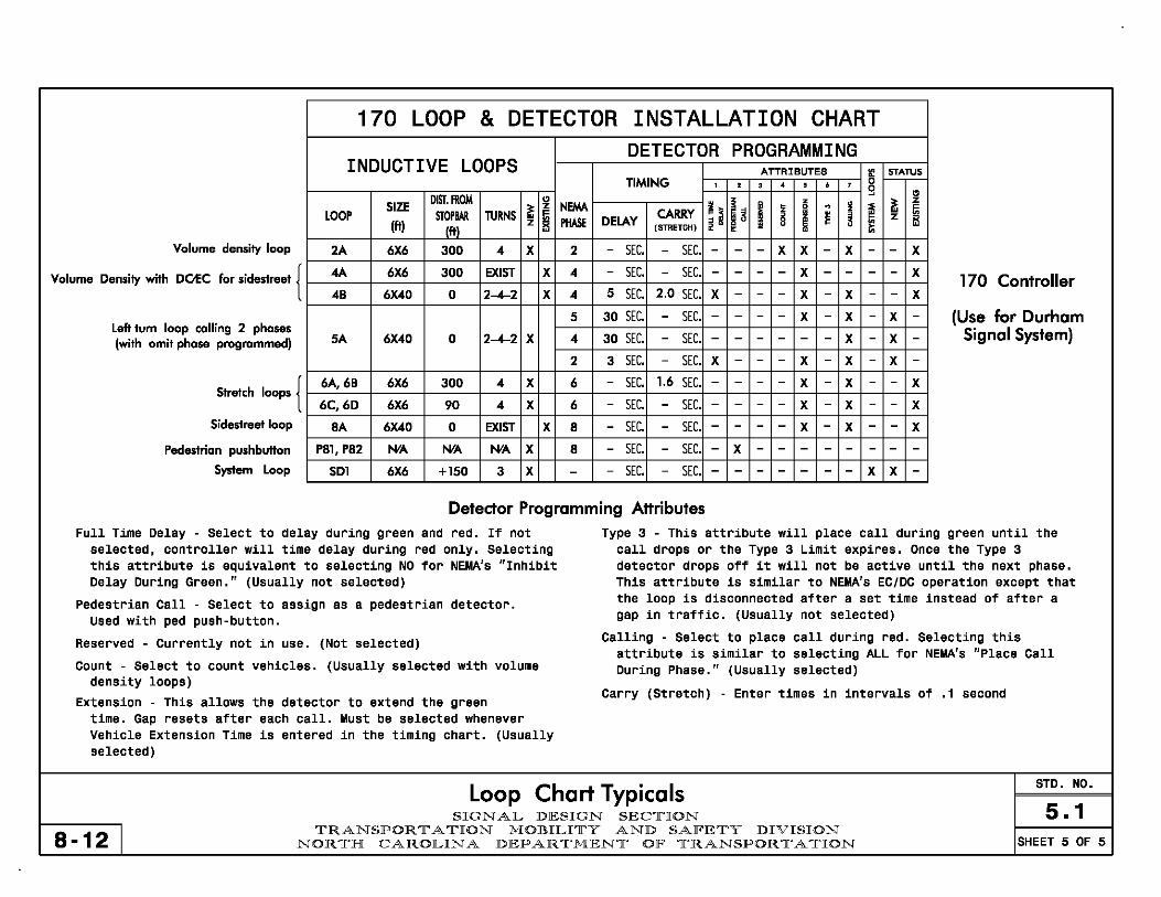
170 LOOP & DETECTOR INSTALLATION CHART DETECTOR PROGRAMMING
INDUCTIVE LOOPS ATTRIBUTES II! STATUS TIMING , , , • , • , 0
DIST.IltOM '3 " SIZE " NEIM ~ ~ h I
z !1 ~
z ~
z • 0 . ! .. LOOP SJOPBAR TURNS ~ DELAY CARRY § i ~ ~ z ~ (It) z PHASE . -
(It) (STRETCH) •• • Volume density loop 2A 6X6 300 4 X 2 - SEC. - SEC. - - - X X - X - - X
Volume Density with DOEC for sideslreet { 4A 6X6 300 EXIST X 4 - SEC. - SEC. - - - - X - - - - X 170 Controller 4B 6X40 0 2-4-2 X 4 5 SEC. 2.0 SEC. X - - - X - X - - X
5 30 SEC. - SEC. - - - - X - X - X - (Use for Durham Left tum loop calling 2 phases
5A 6X40 0 2-4-2 X 4 30 SEC. SEC. X X Signal System) (with omit phase programmed) - - - - - - - - -2 3 SEC. - SEC. X - - - X - X - X -
Stretch loops { 6A,6B 6X6 300 4 X 6 - SEC. 1.6 SEC. - - - - X - X - - X
6C,6D 6X6 90 4 X 6 - SEC. - SEC. - - - - X - X - - X Sideslreet loop 8A 6X40 0 EXIST X 8 - SEC. - SEC. - - - - X - X - - X
Pedestrian pushbutton P8l, P82 N'A N'A N'A X 8 - SEC. - SEC. - X - - - - - - - -System Loop SDl 6X6 +150 3 X - - SEC. - SEC. - - - - - - - X X -
Detector Programming Attributes Full Time Delay - Select to delay during green and red_ If not Type 3 - This attribute will place call during green until the
selected, controller will time delay during red only_ Selecting call drops or the Type 3 Limit expires. Once the Type 3 this attribute is equivalent to selecting NO for NEMA's "Inhibit detector drops off it will not be active until the next phase. Delay During Green." (Usually not selected) This attribute is similar to NEMA's EC/DC operation except that
Pedestrian Call - Select to assign as a pedestrian detector. the loop is disconnected after a set time instead of after a
Used with ped push-button. gap in t raff iC. (Usually not selected)
Reserved - Currently not in use. (Not selected) Calling - Select to place call during red. Selecting this attribute is similar to selecting ALL for NEMA's "Place Call
Count - Select to count vehicles. density loops)
(Usually selected with volume During Phase." (Usually selected)
Extension - This allows the detector to extend the green Carry (St retch) - Enter times in intervals of .1 second
time. Gap resets after each call. Must be selected whenever Vehicle Extension Time is entered in the timing chart. (Usually selected)
Loop Chart Typicals STD. NO_
S .1 SIGNAL DESIGN SEC1I"ION
8-12 I 1I"RANSPOR 11" A 1I"ION MOBILI1I"Y AND SAFE1I"Y DIVISION
NOR1I"H CAROLINA DEPAR 1I"MEN1I" OF 1I"RANSPOR 11" A 1I"ION SHEET 5 OF 5

For All Plans Oasis 2070L Timing Chart (Part 1)
• Main St reet : Side Streets, Lefts, and Main 55 mph (88 km/hr) - 14 sec Street Stopbar Detection: 50 mph (80 km/hr) - 14 sec Set to 4-8 sec, depending 45 mph (72 km/hr) - 12 sec on size of detection area, 40 mph (64 km/hr) - 12 sec grade, truck traffic, etc. OASIS 2070L TIMING CHART
:535 mph (56 km/hr) - 10 sec Typically 7 sec. PHASE
• Main Street - Typically 2.0 sec for stretch detection,
~ FEATURE 2 4 5
3.0 sec for low speed detection. For volume density, amount of time required to get vehicle traveling 5 mph I_ Min Green 1 '" 10 7 7 (8 kph) under the speed limit from upstream loop to I- Extension 1 '" 3.0 1.0 3.0 stop line, generally 6.0 sec.
~ Max Green 1 '" 45 20 25 Side Street - Typically 1.0-3.0 sec. Adjust for size of /; detection area, grade, truck traffic, etc. ~ Yellow Clearance 3.6 3.7 3
• Maximum green times may be determined with the help of fe Red Clearance 1.9 2.1
a software package. Alternately, a hand calculation ~ Red Revert 5.0 2.0 may be suitable: ~ Walk" 4 -
Max Green = 4 + 2 ( Heaviest PHV ~er lane) ~ Don't Walk 1 3600/est cycle length 12 -
PHV = Peak hour volume Seconds Per Actuation· - -
• See STD. NO. 5.2.2 Max Variable Initial'" - -
• A type of Backup Protection. Typically set to 5.0 for Time Before Reduction'" - -
phase(s) used, otherwise default is 2.0 sec. (See Std. 2.3) Time To Reduce'" - -
• Typically 4 -7 seconds Minimum Gap - -
• See STD. NO. 6.0 ;/; fo Recall Mad. MIN RECALL -
f- Vehicle Call Memory YELLOW -• None, Min Recall, Max Recall, Soft Recall, Ped Recall or fo Dual Entry Ped Soft Recall - 0
fa Simultaneous Gap ON • None, Red, or Yellow (See Definitions)
'" These values may be field adjusted. Do not adjust
• On or not selected (see Definitions) Min Green and Extension times for phases 2 and 6 lower than what is shown. Min Green for all other
• On or not selected, usually selected (see Definitions) phases should not be lower than 4 seconds.
Note: For Pre-Timed Signal, set Extension 1 to 0.0 and Recall Position to Max Recall. Enter N/A for Vehicle Call Memory.
Signal Plan Timing Chart STD. NO.
SIGNAL DESIGN SEC1r'ION 5.2.1 7-09 I
1r'RANSPOR 1r' A 1r'ION MOBILI1r'Y AND SAFE1r'Y DIVISION NOR1r'H CAROLINA DEPAR 1r'MEN1r' OF 1r'RANSPOR 1r' A 1r'ION SHEET 1 OF 6
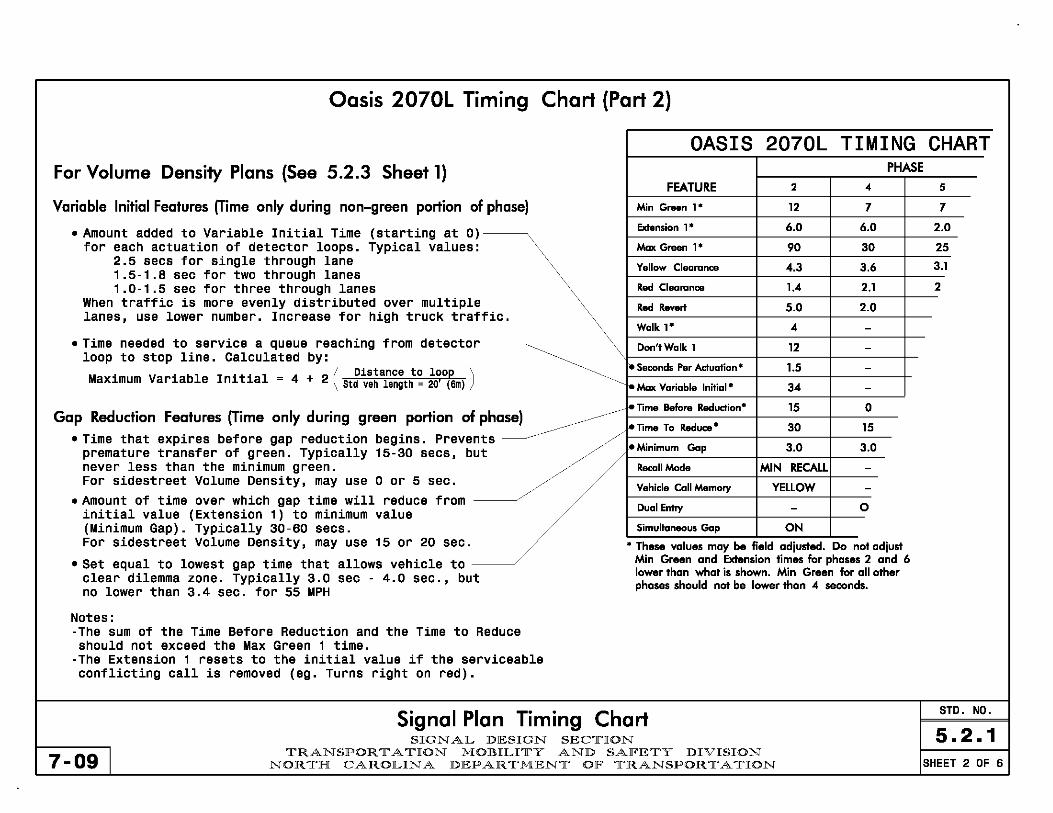
Oasis 2070L Timing Chart (Part 2)
OASIS 2070L TIMING CHART For Volume Density Plans (See 5.2.3 Sheet 1) PHASE
FEATURE 2 -4 5
Variable Initial Features (Time only during non-green portion of phase) Min Gnten 1· 12 7 7
• Amount added to Variable Initial Time (starting at 0) Extension 1" 6.0 6.0 2.0
for each actuation of detector loops. Typical values: Max Green 1· 90 30 25 2.5 secs for single through lane
Yellow Clearance 1.5-1.8 sec for two through lanes 4.3 3.6 3.1
1.0-1.5 sec for three through lanes Red Clearance 1.4 2.1 2 When traffic is more evenly distributed over multiple Red Rove" S.O 2.0 lanes, use lower number. Increase for high truck traffic.
Walk 1· -4 -• Time needed to service a queue reaching from detector Don'tWalk 1 12
~ -
loop to stop line. Calculated by: I- Seconds Per Actuation" 1.5 M' V· bl I . t' I - 4 2 ( Distance to loop ) -
aXl.mum ana e nl. l.a - + Std yeh length 20' (6m) ~ Max Variable Initial" 34 -
Gap Reduction Features (Time only during green portion of phase) ~ I- Time Before Reduction· lS 0
feTime To Reduce- 30 lS
.,;., ,."' .. ,;, .. ''',,' '" ",",,;," "" .. " "," .. " //~// fe Minimum Gap 3.0 3.0 premature transfer of green. Typically 15-30 secs, but never less than the minimum green. Recall Mode MIN RECALL -For sidestreet Volume Density, may use 0 or 5 sec.
Vehicle Call Memory YELLOW -• Amount of time over which gap time will reduce from
Dual Entry - 0 initial value (Extension 1) to ml.nl.mum value (Minimum Gap). Typically 30-60 secs. Simultaneous Gap ON For sidestreet Volume Density, may use 15 or 20 sec. .. These values may be field adjusted. Do not adjust
• Set equal to lowest gap time that allows vehicle to Min Green and Extension times for phases 2 and 6
clear dilemma zone. Typically 3.0 sec - 4.0 sec., but lower than what is shown. Min Green for all other
no lower than 3.4 sec. for 55 MPH phases should not be lower than .4 seconds.
Notes: -The sum of the Time Before Reduction and the Time to Reduce should not exceed the Max Green 1 time.
-The Extension 1 resets to the initial value if the serviceable conflicting call is removed (eg. Turns right on red).
Signal Plan Timing Chart STD. NO.
SIGNAL DESIGN SECTION 5.2.1 7-09 I
TRANSPORTATION MOBILITY AND SAFETY DIVISION NORTH CAROLINA DEPARTMENT OF TRANSPORTATION SHEET 2 OF 6

SE-PAC 2070 Timing Chart (Burlington, Hickory and Raleigh Signal Systems)
For All Plans • See Sheet 1 , Min Green 1 SE-PAC 2070 TIMING CHART • See Sheet 1, Extension 1
• See Sheet 1, Max Green 1 FEATURE 2 4 5
• See STD. ND. 5.2.2 r- Min Green ... 10 7 7
• See Sheet 1 , Walk 1 r- Passage Gap • 3.0 2.0 2.0
• See Sheet 1 , Don't Walk 1 r- Maximum Green'" 45 25 15
For Volume Density Plans r- Yellow Change 3.9 3.4 3.0
• See Sheet 2, Seconds per Actuation r- Red Clear 1.8 2.1 2.2
r-Walk· - - -• See Sheet 2, Maximum Variable Initial r- Pedestrian Clear - - -• See Sheet 2, Time Before Reduction
.~.~. ~ Added Initial· - -
• See Sheet 2, Time to Reduce ~ Maximum Inilial* - -
• See Sheet 2, Minimum Gap ~ Time Before Redudion " - -
For All Plans I'- Time To Reduce • - -
~ Minimum Gap - -• None, Min Recall, Max Recall, Soft Recall, or Ped Recall
------- t-. Recall Mode MIN RECALL -• Lock or Non-Lock (See Definitions) t- Vehicle Call Memory LOCK NON LOCK
• On or not selected (see Definitions) Dual Entry ON
• On or not selected, usually selected (see Definitions) Simultaneous Gap ON ON
Note: For Pre-Timed Signal, set Extension 1 to 0.0 and Recall ... These values may be field adiusted. Do not adiust
Min Green and Extension times for phases 2 and 6 Position to Max Recall. Enter Non-Lock for Vehicle Call Memory. lower than what is shown. Min Green for all other
Note: SE-PAC Software cannot use Red Revert for backup protection. phases should not be lower than 4 seconds.
Phase omits must be used.
Signal Plan Timing Chart STD. NO.
SIGNAL DESIGN SECTION 5.2.1 8-12 I
TRANSPORTATION MOBILITY AND SAFETY DIVISION NORTH CAROLINA DEPARTMENT OF TRANSPORTATION SHEET 3 OF 6

Naztec Apogee 2070 Timing Chart (Greensboro Signal System)
For All Plans NAZTEC APOGEE 2070 TIMING CHART • See Sheet 1 , Min Green 1
PHASE • See Sheet 1, Extension 1
FEATURE 2 4 5
• See Sheet 1, Max Green 1 ~Min Green ... 12 7 7
• See STD. NO. 5.2.2 ~ Gap, Extension ... 6.0 2.0 2.0 • See Sheet 1 , Walk 1
~ I'- Maximum Green 1 ... 90 30 20
• See Sheet 1 , Don't Walk 1 r- Maximum Green 2 ... 110 25 25
For Volume Density Plans I- Yellow Clear 5.1 3.8 3.0
r- Red Clear 1.2 1.9 2.1 • See Sheet 2, Seconds per Actuation
f-Walk· 4 - -• See Sheet 2, Maximum Variable Initial r- Pedestrian Clear 16 - -• See Sheet 2, Time Before Reduction
~ ~ Added Initial'" 1.5 -
• See Sheet 2, Time to Reduce ~ Maximum Initial'" 34 -
• See Sheet 2, Minimum Gap I'- Time Before Redudion ... 15 -
For All Plans I'- Time To Reduce ... 60 -I'- Minimum Gap 3.0 -
• None, Min Recall, Max Recall, Soft Recall, or Ped Recall ~ f- Recall Mode MIN RECALL -
• Yes or No (See Definitions) t- Lock Calls YES NO
• On or not selected (see Definitions) r- Dual Entry ON
• On or not selected, usually selected (see Definitions) r- Simultaneous Gap ON ON
Note: For Pre-Timed Signal, set Gap, Extension 1 to 0.0 and Recall ... These values may be field adjusted. Do not adjust
Min Green and Extension times for phases 2 and 6 Position to Max Recall. Enter No for Lock Calls. lower than what is shown. Min Green for all other
Note: Naztec Apogee Software can not use Red Revert for backup phases should not be lower than 4 seconds.
protection. Phase omits must be used.
Signal Plan Timing Chart STD. NO.
SIGNAL DESIGN SECTION 5.2.1 7-09 I
TRANSPORTATION MOBILITY AND SAFETY DIVISION NORTH CAROLINA DEPARTMENT OF TRANSPORTATION SHEET 4 OF 6

For All Plans NEMA Timing Chart (Also for Cary 2070N Signal System) • See Sheet 1, Min
• See Sheet 1, Exte
• See STD. NO. 5.2
• See Sheet 1, Max
• None, Min Recall
Green 1
~ . ";":~':::.' nsicn 1 NEMA TIMING CHART
.2 PHASE Green 1 2 4 6
, Max Recall, Soft Recall or Ped Recall 12 7 12
• Lock or Nonlock
• See Sheet 1, Walk 1
t Walk 1
ty Plans (See 5.2.3 Sheet 1) • See Sheet 1, Don'
For Volume Densi Variable Initial Feature s (Active only during non-green portion of phase)
• Number of vehicle Maximum Initial v is zero. If neede Minnesota Microtr B4 Add may be cal
s that arrive that will not count toward alue. For most controllers, this value d (such as Traconex TMP 390 and onics 800 controllers), the Actuation culated:
Actuation B4 Add = Min green - 4 2
• Amount added to V ariable Initial Time (starting at 0) for each actuatio
2.5 secs for 1.5·1.8 sec 1.0·1.5 sec
When traffic is m lanes, use lower For the Traconex
2.0 secs for 1.3-1.5 sec f 1.0-1.3 sec f
• See Sheet 2, Maxl.
n of detector loops. Typical values: single through lane
for two through lanes for three through lanes ore evenly distributed over multiple number. Increase for high truck traffic. and Minnesota Microtronics controllers: single through lane or two through lanes or three through lanes mum Variable Initial
Gop Reduction Feotu Notes:
res see Sheet 2
-The sum of the Time Before Reduction and the Time to Reduce should not exceed the Max Green 1 time.
-The Passage/Gap resets to the initial value if the serviceable conflicting call is removed (eg. Turns right on red).
" PassageGap' 6.0 1.0 6.0
" Yellow Change Inl 4.3 3.6 4.
• Red Clearance 1.4 2.1 1
-. Maximum 1* 90 20
-. Recall Position MIN RECALL NONE • Vehicle Call Memory LOCK NONLOCK
• Walk' 4 -• Flashing Dan" Walk 12 -
Volume Density ON OFF
., Actuation B4 Add'" 0 -Sec Per Actuation· 2.5 -
, Maximum Initial· 34 -, Time B4 Reduction" 15 -, Time To Reduce'" 30
, Minimum Gap 3.0
... These values may be field adjusted. Do not adjust Min Green and Extension times for phases 2 and 6 lower than what is shown. Min Green for all other phases should not be lower than 4 seconds.
Note: For Pre-Timed Signal, set Passage/Gap to 0.0 and Recall Posl.tl.on to Max Recall. Enter N/A for Vehicle Call Memory.
Note: NEMA Equipment cannot use Red Revert for backup protection. Phase omits must be used.
Signal Plan Timing Chart 5.2.1 STD. NO.
7-09 SIGN AL DESIGN SEC1['ION
1['RANSPOR 1[' A 1['ION MOBILI1['Y AND SAFE1['Y DIVISION NOR 1['H CAROLINA DEPAR 1['MEN1[' OF 1['RANSPOR 1[' A 1['ION SHEET 5 OF 6
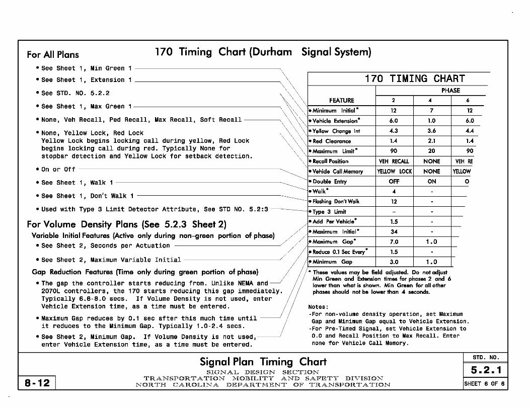
For All Plans , 70 Timing Chart (Durham Signal System) o See Sheet 1, Min Green 1
o See Sheet 1, Extension 1
OSee STD. NO. 5.2.2 ----------------------------------------~
OSee Sheet 1, Max Green 1------------------------------------~
o None, Veh Recall, Ped Recall, Max Recall, Soft Recall --------~
o None, Yellow Lock, Red Lock ----------------------------------, Yellow Lock begins locking call during yellow, Red Lock begins locking call during red. Typically None for stopbar detection and Yellow Lock for setback detection.
o On or Off ----------------------------------------------------~
o See Sheet 1, Walk 1 ------------------------------------------__
o See Sheet 1, Don't Walk 1
o Used with Type 3 Limit Detector Attribute, See STD NO. 5.2:3---------t~~~;,:._----_1----~--_1--~----t_--
For Volume Density Plans (See 5.2.3 Sheet 2) • Add Per Vehicle * 1.5 -
of phase) ;3""Maximum Initial' 34 . Variable Initial Features (Active only during non-green portion
_ __________________________ J ,"Maximum Gap' 7.0 1.0 o See Sheet 2, Seconds per Actuation
,
flfRedUce 0.1 Sec Every' 1.5 . o See Sheet 2, Maximum Variable Initial --------------------------" fMinimum Gap 3.0 1.0
Gap Reduction Features (Time only during green portion of phase) , These values may be field adiusted. Do not adiust .. Min Green and Extension times for phases 2 and 6
o The gap the controller starts reducl.ng from. Unll.ke NEMA and lower than what is shown. Min Green lor all other 2070L controllers, the 170 starts reducing this gap immediately. phases should not be lower than 4 seconds. Typically 6.8·8.0 secs. If Volume Density is not used, enter Vehicle Extension time, as a time must be entered.
o Maximum Gap reduces by 0.1 sec after this much time until ----~ it reduces to the Minimum Gap. Typically 1.0·2.4 secs.
o See Sheet 2, Minimum Gap. If Volume Density is not used,----~ enter Vehicle Extension time, as a time must be entered.
Notes: -For non-volume density operation, set Maximum Gap and Minimum Gap equal to Vehicle Extension.
-For Pre-Timed Signal, set Vehicle Extension to 0.0 and Recall Position to Max Recall. Enter none for Vehicle Call Memory.
Signal Plan Timing Chart SIGN AL DESIGN SEC1['ION
STD. NO.
5.2.1 8-12 I
1['RANSPOR 1[' A 1['ION MOBILI1['Y AND SAFE1['Y DIVISION NOR 1['H CAROLINA DEPAR 1['MEN1[' OF 1['RANSPOR 1[' A 1['ION SHEET 6 OF 6

Through Movement Clearance Distances
I I
Need to clear right Round distances up to the turn (if signalized) nearest 5' (1m) increment
I 1 unless distance is very long
~ ~ ~ 1 -1
1
1 '\.. -1--1---
~ ~
~
1 ~ : f-- .- ~
Yield Sign b... ~
1 ~ ~ 1
1 1 I--- .- ~
1 1 --:r 1 r-J. -1 - 1 ~ r--~
1 (~ 1 1 ~
~
'\ 1 ~
1 ~
1 ~ -~ ~: ~
~ 1 ~ -- ~
= ~ 1
~ ~ - 1
~ ~
1 1 ~ - 1 1
~
~ Ir I ~ ~~ l
~
J'\: -I
When pedestrian signals
1 t 1 are present, clear to the
near side of the crosswalk ~ ,. 1 1
Change and Clearance Intervals STD. NO.
SIGN AL DESIGN SEC1['ION 5.2.2 7-05 I
1['RANSPOR 1[' A 1['ION MOBILI1['Y AND SAFE1['Y DIVISION NOR1['H CAROLINA DEPAR 1['MEN1[' OF 1['RANSPOR 1[' A 1['ION SHEET 1 OF 4
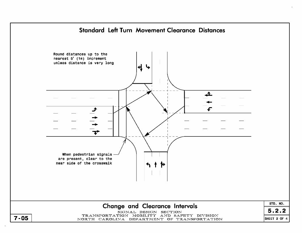
7-05
Standard Left Turn Movement Clearance Distances
Round distances up to the nearest 5' (1m) increment unless distance is very long
--When pedestrian signals ~
are present, clear to the near side of the crosswalk
I
I I
\
~t~ I I
Change and Clearance Intervals SIGN AL DESIGN SEC1['ION
1['RANSPOR 1[' A 1['ION MOBILI1['Y AND SAFE1['Y DIVISION NOR 1['H CAROLINA DEPAR 1['MEN1[' OF 1['RANSPOR 1[' A 1['ION
STD. NO.
5.2.2 SHEET 2 OF 4
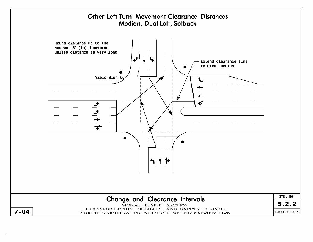
7-04
Other Left Turn Movement Clearance Distances Median, Dual Left, Setback
Round distance up to the nearest 5' (1m) increment unless distance is very long
• Yield Sign b..
-•
I
~ ~ ~ •
Extend clearance line to clear median
/ L-....:,..~ - -:- - ~ - - - - ,-------____ I 'l.
•
~I t I~
Change and Clearance Intervals SIGN AL DESIGN SEC1['ION
1['RANSPOR 1[' A 1['ION MOBILI1['Y AND SAFE1['Y DIVISION NOR 1['H CAROLINA DEPAR 1['MEN1[' OF 1['RANSPOR 1[' A 1['ION
STD. NO.
5.2.2 SHEET 3 OF 4

Determination of Yellow Change and Red Clearance Intervals
Yellow Change Interval Notes
"Design speed is the speed limit unless a speed study determines v that the 85th percentile speed is faster or intersection
Yellow interval = t + 2a + 64.4g geometrics compel vehicles to traverse the intersection slower.
t perception reaction time, typically 1.5 seconds ""The purpose of a stakeholder discussion is to provide advance
= notification and involvement to stakeholders and provide an v = design speed", in ft/sec opportunity to consider possible countermeasures. a = deceleration rate, typically 11.2 ft/sec 2
g = grade For most left turn lanes, assume a speed of 20 mph (32 kph) to 30 mph (48 kph). For locations with unusual conditions a higher
Round up to nearest 0.1 second. or lower speed may be appropriate.
Minimum yellow change interval is 3.0 seconds. For separate left turn intervals.
phases, calculate yellow and red
Hold stakeholder discussion"" when calculated yellow change interval is longer than 6.0 seconds. For left turns without a separate phase, calculate yellow and
red times for both the through movement and the left turn
Red Clearance Interval movement. Use the highest yellow and enough red to equal the highest total time.
Red interval =.JL w = width of intersection, in feet Where existing times are higher than calculated times, use the v v = design speed", in ft/sec calculated values unless there is a documented history of the
need for higher times. If approach is high speed and existing If the initial calculation results in an all red time times are significantly higher than the calculated times, use longer than 3.0 seconds, recalculate the red time as the calculated values but consider adding a note to the plan follows: to direct field forces to reduce the time incrementally.
Recalculated red interval = ~(.JL. 3) + 3 Include in the note how much and how often to reduce time until 2 v the final value is reached. (Ex. Existing Yellow Change Interval
Round up to nearest 0.1 second. for phase 2 may be decreased by 0.2 seconds per week until the required value is reached.)
Red clearance interval should be between 1.0 and 6.0 sec.
Hold stakeholder discussion"" when recalculated Where revising a location or adding a new signal along a
red corridor, consider comparing clearance times at adjacent clearance interval is longer than 4.0 seconds. intersections to new calculations to meet driver expectations.
Sources: A Polic~ on Geometric Design of Highwa~s and Streets, Traffic Engineering Handbook, Fifth Edition, Institute Fourth Edition, American Association of State Highway of Transportation Engineers, 1999. and Transportation Officials, 2001.
Change and Clearance Intervals STD. NO.
SIGNAL DESIGN SECTION 5.2.2 12-101
TRANSPORTATION MOBILITY AND SAFETY DIVISION NORTH CAROLINA DEPARTMENT OF TRANSPORTATION SHEET 4 OF 4

Variable Initial Parameters
Variable initial operation increases the MIN Green interval Maximum Initial = 34 sec - --------------------- in a manner dependent upon the number of vehicle actuations
\ placed on the phase while it is in the Yellow or Red c Sec per Actuation interval. The variable initial interval is calculated as a ., - function of the vehicle actuations and the MIN Green, ., ..
= 2.5 sec ~." Queue Seconds Per Actuation, and MAX Variable Initial settings. C) c 0 reaches The following relationship calculates the variable initial - U .2 CD
."!:: ..!!!. detector interval: .E loop Initial Interval = (I 0/ Vehicle Actuations) X (Seconds Per Actuation Selling)
Minimum Green = 12 sec - ------- ------ --------------
If the calculated initial interval is less than the MIN One vehicle Green setting, the MIN Green time will be used as the
arrival initial interval. If the calculated initial interval is greater than the MAX Variable initial setting, the MAX
va = Beginning of phase red va Vehicle aduations Variable initial will be used as the initial interval. with no vehicles waiting
Gap Reduction Parameters
Time B4 Reduction Time to Reduce
Extension/ ' 15 sec I 45 sec Gap Reduction reduces the allowable gap between successive I- -I- • vehicle actuations by dynamically decreasing the extension Passage/Gap = 6.0 sec -, time. The rate of reduction is based on the setting of the
., - , Extension, Minimum Gap, and Time to Reduce settings. Using E .. , this method, the gap will be reduced by the following i=~
0 , relationship:
Q.U , a ., C)S ,
Reduction = ExteosiQO - Minimum Gap x (Current Green Interval Time - TBR) ,
TTR Minimum Gap = 3.0 sec - _______ J ____
----------, This reduction begins when the Green interval has timed ,
, Maximum Green the Time Before Reduction (TBR) setting. Reduction of the
"
• allowable gap will continue until the gap reaches a value 90 sec , , , ,
equal to or less than the Minimum Gap In the presence of
to t, 15 60 90 continual vehicle actuations, the phase will not gap out, to = Beginning of phase green
Phase time (seconds) even if the gap has been reduced to zero. t1 = Serviceable conflicting call arrives green
Volume Density Timing Example 2070L and NEMA Controllers STD. NO.
SIGNAL DESIGN SEClrION 5.2.3 7-04 I lrRANSPOR 11' A lrION MOllULIlrY AND SAlFElrY DIVISION
NORlrH CAROLINA DEPARlrMENlr OlF lrRANSPOR 11' A lrION SHEET 1 OF 2

Maximum Initial = 34 sec -
Minimum Initial = 12 sec -
Vo = Beginning of phase red with no vehicles waiting
Maximum Gap = 7.0 sec -
Vehicle Extension = 6.0 sec -
to = t, =
1)-E .. t="'g
0 Q.U
" I) C).!!!.
Minimum Gap = 3.0 sec -
Beginning of phase green
Serviceable conflicting call arrives
- - - - - - - - - - - - - - - - - - - - - ,-------,----
\ Add per Vehicle = 2.5 sec -----I
One vehicle arrival
Vehicle actuations
I Reduce 0.1 I - - - - - - - -, - '- - I Sec Every I
: --~1.5 sec :
I 0.1 sec ,
Queue reaches
detector loop
I (Step size) I
I
- - - - - - - -r - - - - - - - - - - - - - - - - - - L-__
Maximum Limit 90 sec
t, 60 90
Phase green time (seconds)
Variable Initial
Parameters
Gap Reduction
Parameters
Note: The controller begins timing the gap reduction from the Maximum Gap (7.0 sec) when it gets a conflicting call; however, the 'real' maximum gap is the Vehicle Extension (6.0 sec). The Vehicle Extension time will never go above 6.0 seconds. The time the controller takes to reach the Vehicle Extension from the Maximum Gap is the 170's version of Time 64 Reduction.
Volume Density Timing Example - 170 Controller STD. NO.
5.2.3 7-04 I
SIGN AL DESIGN SEC1['ION 1['RANSPOR 1[' A 1['ION MOBILI1['Y AND SAFE1['Y DIVISION
NOR 1['H CAROLINA DEPAR 1['MEN1[' OF 1['RANSPOR 1[' A 1['ION SHEET 2 OF 2

Standard Signal Plan Legend Other Common Symbols
LEGEND PROPOSED
PROPOSED EXISTING ~ Modified Pedestrian Head
Metal Strain Pole
Metal Pole with Mastarm
Signal Pedestal
Directional Drill
0-- Traffic Signal Head ~ Modified Signal Head
---1 Sign
9 Pedestrian Signal Head With Push Button & Sign
0 ) Signal Pole with Guy
~ Signal Pole with Sidewalk Guy ( ) Inductive Loop Detector
C8J Controller & Cabinet D Junction Box
• .. N/A ---1
T • • -. C:::::::::J
I' 71 ",--x ~
•
[Q] roc-----
0 -DD-
():::J -c=:::> [M] N/A
Out of Pavement Detector
Video Detection Area
-------- 2-in Underground Conduit -------
Out of Pavement Detection Area
Master Controller & Cabinet
Railroad Cantilever
Railroad Gate and Flasher
Railroad Tracks N/A Right of Way ----
") Directional Arrow ")
• Note:
N/A N/A
• --N/A
• Construction Zone Drums
Construction Zone
New Pavement
Symbols for utilities, hydrology, property lines, etc. should mirror standards set N/A
Wheelchair Ramp
Wheelchair Ramp
Sign I.D. by NCDOT's Roadway Design Unit. @
7-09 I
Common Drawing Symbols S I GN A L D E S IGN S E CTI ON
TRANSPORT A T ION MOB ILITY AND SAFE T Y D IVISION NORTH CAROlLINA DEPAR TMENT OF T R ANSPORTAT ION
EXISTING
N/A [)
0
• N/A .... -c=:::> "M""f1 Ub~
~ ~
i
• • • -N/A
CW~® IIlI\
® STD. NO.
5.3 SHEET 1 OF 1
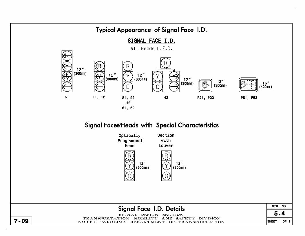
51
7-09
12" (300mm)
Typical Appearance of Signal Face 1.0.
11, 12
SIGNAL FACE I.D. All Heads L.E.D.
21, 22 42
61, 62
12" (300mm)
42
rif'Il 12" ~ (300mm)
P21, P22
Signal Faces+ieads with Special Characteristics
Optically programmed
Head
R 12"
Y (300mm)
Section with
Louver
® fv\ 12" o (300mm)
o
Signal Face 1.0. Details SIGN AL DESIGN SEC1['ION
1['RANSPOR 1[' A 1['ION MOBILI1['Y AND SAFE1['Y DIVISION NOR 1['H CAROLINA DEPAR 1['MEN1[' OF 1['RANSPOR 1[' A 1['ION
t : ::: 16" .. -, .. -, : __ :: __ : (400mm)
P61, P62
STD. NO.
5.4 SHEET 1 OF 1

Project Type Indicate whether 'New Installation,' 'Signal Upgrade,' or 'Temporary Signal.'
Graphic Scale Include a graphic scale on all plans.
Plan Description Description should include:
# Phases Type of Actuation w/ Special Features (if any) Isolated or System (including type)
Text and Lettering -Letter sizes should approximate the following:
Title block street names and title heads ... 3/1Sin (5mm) All other lettering ......................... l/Bin (3mm)
-List the routes in the title block using the word "at", not "and", as follows:
SR XXXX (Tree Avenue) at SR XXXX (Stump Drive) -OR-
SR XXXX (Tree Avenue) at SR XXXX (Stump Drive)/NC 123 (Branch Street)
Metric Block For metric plans, include the metric block in the upper righthand corner.
North Arrow For Spot Safety projects, align the main street to run horizontally across the plan where possible. For Contract projects, align the plan in the same general direction as the roadway plans. For closed loop system projects, align signal plan sheets in the same general direction as the cable routing plans where possible.
Address For plans developed in house, include the department logo with the Signals & Geometrics Section's address in the title block.
For plans developed by private engineering firms, include the department logo with the Signals & Geometrics Section's address in the title block and the firm's name with address on the plan sheet beside the title block.
For plans developed by municipalities, include the department logo with the Signals & Geometrics Section's address in the title block and the municipality's name with address on the plan sheet beside the title block.
For plans developed by private engineering firms for a municipality, include the department logo with the Signals & Geometrics Section's address in the title block and the firm's name with address on the plan sheet beside the title block.
Note: Private engineering firms and municipalities are responsible for placing their name with address on the plans. Company or municipal logos are permitted providing they do not detract from the plan.
STD. NO. Miscellaneous Drawing Format Items
5.5 7-04 I
SIGN AL DESIGN SEC1['ION 1['RANSPOR 1[' A 1['ION MOBILI1['Y AND SAFE1['Y DIVISION
NOR 1['H CAROLINA DEPAR 1['MEN1[' OF 1['RANSPOR 1[' A 1['ION SHEET 1 OF 4
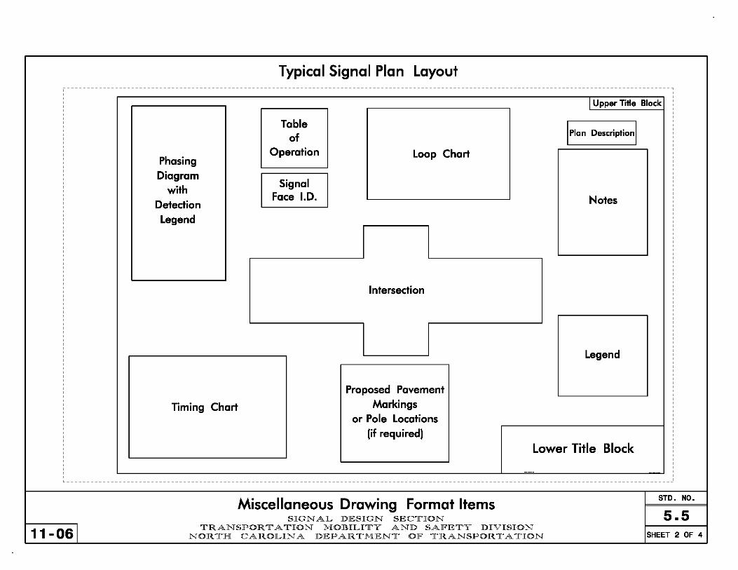
Typical Signal Plan Layout ------------------------------------------------------------------------------------------------------------------------------------------------------,
I Upper Title Block
Table Iplan DesCriPtionl of
Phasing Operation Loop Chart
Diagram Signal
with Face 1.0. Notes Detection
Legend
Intersection
Legend
Proposed Pavement
Timing Chart Markings
or Pole Locations
(if required)
Lower Title Block
------
L _______________________________________________________________________________________________________________________________________________________
Miscellaneous Drawing Format Items STD. NO.
SIGNAL DESIGN SECTION 5.5 11-061
TRANSPORTATION MOBILITY AND SAFETY DIVISION NORTH CAROLINA DEPARTMENT OF TRANSPORTATION SHEET 2 OF 4

Typical Border Sheet with Dimensions
~.. 34" (860mm) .~ r 3.0" (80mm) 0.5" (15mm)1 _.--c _______ , _________________________________________________________________________________________________________________________ "
T I~ .. _ .
.. _ ...
E E Typical Upper Title Block It> c •
~ It> PIIOJECT REFERENCE NO. SHEET NIl.
e ------------------ -------
'-------y------For metric plans
5ignal_Uagrade ______________________________ ~
E ,.,."". ".". (¥fa. ." __ U5_16:6Ql_(East-Boule~ardl-- SEAL E
~ 0
______________ at ______________ co _____ 5B_123~_(Elm-5treetl-----Ii) •. oJ ~
------------------------------C\I ~-~
Di:'liliIlL5. _____ likU" nlx ______________ Billig] C\I Pl.AII DATE: ___ AnrlUQQL_ IB'IElED BY: ---------------
75D/I.~'" "',.,..IIC B'5ft PREI'ARED !Y: ___ J_ A _QnL _ IB'IElED !Y: ---------------
~ "'" AEVlSIIJIS DlIT. ~.
0 10 ----------------------------- - - - -- - - --
----------------------------- - - - -- - - -- 8IClINATUIIE ~" _ j ~=~O~_ ----------------------------- - - - -- - - -- SIB. IWEIITDIIY lID. Q;,m1
~ Typical Lower Title Block V E E Ii) ~
~
<& -Ii)
------------------------------------------------------------
0 -- --_. --~ [Alb= ,I ,f -
_L--C _______ , __________________________________________________________________________________________________________________________
Miscellaneous Drawing Format Items STD. NO.
S I GNAL D E S IGN S E CTI ON 5.5 7-09 I
TRANSPORT A T ION MOB ILITY AND SAFE T Y D IVISION NORTH CAROlLINA DEPAR TMENT OF T R ANSPORTAT ION SHEET 3 OF 4

Revisions When revising an existing traffic signal plan, include the revision number, date, and reV1S10n description. Additionally, enclose the revision number in a triangle and place the triangle on the plans near the affected area if needed for clarity.
When the PE making the revision is the same PE who sealed the original plan, the PE initials and dates the revision block and reseals the original plan with the original date.
Signal Upgrade
When the PE making the reV1S10n is different than the PE who sealed the original plan, then a "Revision Seal" block needs to be added to the title block to the left (preferred) or just above the title block on the original plans. In addition, add the text "Not a certified document as to the Original Document but only as to the Revisions· This document originally issued and sealed by 'name,' 'PE number,' on 'date.' This document is only certified as to the revisions."
7-09 I
Signal Upgrade REVISION'\VSEAL ,.,..,. ".". rna. tI.
Not a certifIed document as """""" @ US 16·601 (East Boulevard) ",,:, CARd"" .. i!O. :-,~ :;~i'isSiO;k:;-::. 1\ !I"~ 2 a t to til: OrIgInal Otxument bUt
~r{;,2 ',:' );],J ". .~ Division ~R 12~~ke ~~U~~y St reet) R.lei,1 ~2:.~~3:':::· " ~'- '~.~~ "ll:S=_ ~ '''' ~T" April 2DD4 ""'J" ." Robert J.ztemba.PE. "26486.
Jo1( A .,J'" -...yo' Q(J 2/3/04 . .., . "~\..'i.~, .. " ~ II.tJrwntIi1,... ~.1tC ~ PREPAIIED IV: J A 00& REVIEWED BY:
111111111111\\ 411104 ~'\ I!CAI..E RfVISIO~S INIT. DATE Tfis documer/ Is only certifIed
.~Q_TU"E ~n N 0 40 ~~~~~:~~~~=-~========== =~~= t~~I~~:: as to til: revIsIons. 1H=40· ----------------------------- ----- SI8.IIMIITQlYNO. 05-4321
Miscellaneous Drawing Format Items SIGNAL D E SIGN S ECT I ON
TRANSP O R TATI ON MOBIL I T Y AND SAFE T Y D IVISI ON NOR T H CAROL INA D E PARTME NT OF T R ANSPORTATI ON
STD. NO.
5.5 SHEET 4 OF 4

Signal Cable Calculations
Signal Cable There is only one pay item for signal cable; combine measurements for 16-4 and 16-7 cable. Route cable to m1n1m1ze the length of cable used. Add 3' (1 m) extra in cabinets. Add 3' (1 m) extra at each signal head. Assume 30' (10 m) down poles. Note: Use 2 separate cable runs if there are more than 6 heads on a phase.
Example (See sheet 2)
Heads 61 & 62: 3' (beside head) + 12' + 3' (beside head) + 270' + 30' (down pole) + 10' (to cabinet) + 3' (in cabinet)
Head 11 3' (beside head) + 256' + 30' (down pole) + 10' (to cabinet) + 3' (in cabinet)
Heads 41 & 42: 3' (beside head) + 15' + 3' (beside head) + 105' + 30' (down pole) + 10' (to cabinet) + 3' (in cabinet)
Head 43: 3' (beside head) + 220' + 30' (down pole) + 10' (to cabinet) + 3' (in cabinet)
Heads 31, 32, 33 & 34: 3' (beside head) + 15' + 3' (beside head) + 10' + 3' (beside head) + 12' + 3' (beside head) + 150' + 30' (down pole) + 10' (to cabinet) + 3' (in cabinet)
Heads 21 & 22: 3' (beside head) + 15' + 3' (beside head) + 55' + 30' (down pole) + 10' (to cabinet) + 3' (in cabinet)
Total: 331' + 302' + 169' + 266' + 242' + 119' = 1429'
Round up to nearest 10' = 1430'
7-09 I
Plan Quantity Calculations SIGNAL DESIGN SEClrION
lrRANSPOR 11' A lrION MOllULIlrY AND SAlFElrY DIVISION NORlrH CAROLINA DEPARlrMENlr OlF lrRANSPORlrAlrION
= 331'
= 302'
= 169'
= 266'
= 242'
= 119'
STD. NO.
5.6 SHEET 1 OF 4
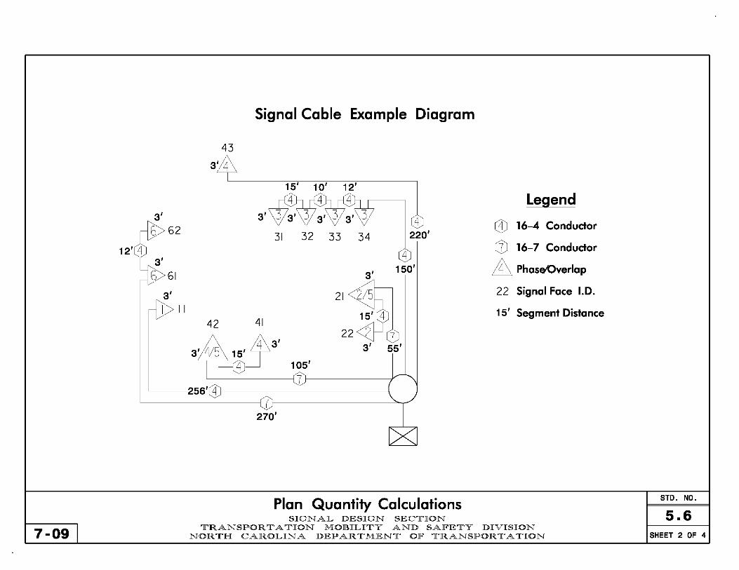
7-09
Signal Cable Example Diagram
Plan Quantity Calculations SIGNAL DESIGN SEC1['ION
1['RANSPOR 1[' A 1['ION MOBILI1['Y AND SAFE1['Y DIVISION NOR 1['H CAROLINA DEPAR 1['MEN1[' OF 1['RANSPOR 1[' A 1['ION
STD. NO.
5.6 SHEET 2 OF 4
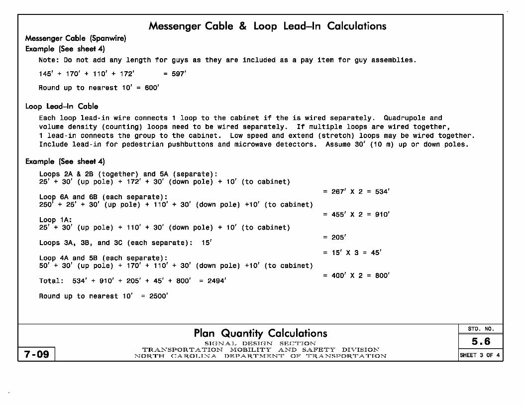
Messenger Cable (Spanwire) Example (See sheet 4)
Messenger Cable & Loop Lead-In Calculations
Note: Do not add any length for guys as they are included as a pay item for guy assemblies.
145' + 170' + 110' + 172' = 597'
Round up to nearest 10' = 600'
Loop Leod-In Coble
Each loop lead-in wire connects 1 loop to the cabinet if the is wired separately. Quadrupole and volume density (counting) loops need to be wired separately. If multiple loops are wired together, 1 lead-in connects the group to the cabinet. Low speed and extend (stretch) loops may be wired together. Include lead-in for pedestrian pushbuttons and microwave detectors. Assume 30' (10 m) up or down poles.
Exomple (See sheet 4)
Loops 2A & 28 (together) and 5A (separate): 25' + 30' (up pole) + 172' + 30' (down pole) + 10' (to cabinet)
= LOOp 6A and 68 (each separate):
267' X 2 = 534'
250' + 25' + 30' (up pole) + 110' + 30' (down pole) +10' (to cabinet) = 455' X 2 = 910'
LOOp lA: 25' + 30' (up pole) + 110' + 30' (down pole) + 10' (to cabinet)
Loops 3A, 38, and 3C (each separate): 15' = 205'
= 15' X 3 = 45' LOOp 4A and 58 (each separate): 50' + 30' (up pole) + 170' + 110' + 30' (down pole) +10' (to cabinet)
Total: 534' + 910' + 205' + 45' + BOO' = 2494' = 400' X 2 = BOO'
Round up to nearest 10' = 2500'
Plan Quantity Calculations SIGNAL DESIGN SEClrION
7-09 I lrRANSPOR 11' A lrION MOllULIlrY AND SAlFElrY DIVISION
NORlrH CAROLINA DEPARlrMENlr OlF lrRANSPORlrAlrION
STD. NO.
5.6 SHEET 3 OF 4

Loop Lead-In & Messenger Cable Example Diagram
50' Separate 4A & 58
\ \ \ I
\ \ I
58 4A \ I
I I I I U II II \\ \\ ~
\ I I I I I I I I I ~
(-P---:-077'77'-+-++-I-l-l- 170' '<::
loop
== == == ==========::::::::.:;::;
25' 2A & 28 Together
5A Separate
7-09
--- .........
)
/
~ ... ====-_ :::r==
loop
Plan Quantity Calculations SIGNAL DESIGN SEC1['ION
1['RANSPOR 1[' A 1['ION MOBILI1['Y AND SAFE1['Y DIVISION NOR 1['H CAROLINA DEPAR 1['MEN1[' OF 1['RANSPOR 1[' A 1['ION
250' Separate 6A & 68
I - ==~=-
6B
6A
STD. NO.
5.6 SHEET 4 OF 4

Typical Pedestrian Heads
Retrofit Installation Standard - Countdown Pedestrian Head Alt/Preemption Pedestrian Head
11" (280mm~ Symbol Minimum
Pedestrian Head Guidelines -With pretimed operation, use "Ped Recall" when push buttons are not used_
-Also with pretimed operation, "Max Time" should not be less than the total of "Walk" and "Flashing Don't Walk" times_
-Typically, do not use countdown pedestrian heads with railroad preemption (unless pretimed operation)_
-Countdown heads may not be compatible with some forms of EV or Fire Preemption_
-Existing 9" (225 mm) Housing, 2 section pedestrian heads are allowed when distance to head is less than 100 feet (30m)_
-For head numbering refer to Std_ No_ 3.0:1.
, , , , , - - --I , , , , ,
9" (225mm) Numerals
16" (400mm) Housing
*
Pedestrian Timing
9" (225mm) Symbol
-"Walk Time": Minimum 4 to 7 seconds, depending on pedestrian volume and characteristics.
-"Flashing Don't Walk Time" (FDW): Enough time to get from curb or shoulder to farside of the farthest traveled lane (D). Assume 4 feet (1.2m) per second (S), minus the concurrent yellow change interval (VC). Use slower travel speed where a high percentage of slower moving pedestrian traffic can be expected.
FDW=%-VC
STD. NO. Pedestrians Heads & Timing
6.0 7-09
S I GN AL lDESIGN SECTI ON TRANSPORTATION MOBILITY AND SAFETY lDIVISION
NORTH CAROLINA DEPARTMENT OF TRANSPORTATION SHEET 1 OF 1
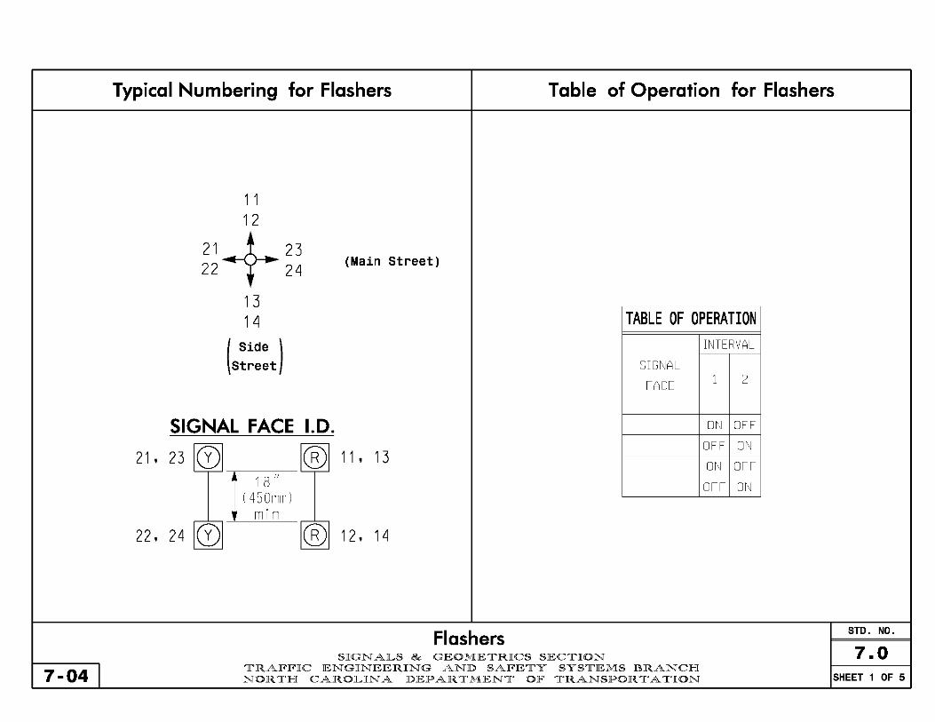
7-04 I
Typical Numbering for Flashers Table of Operation for Flashers
1 1 12
21+23 22 24
13
(Main Street)
14 TABLE OF OPERATION
(Side )
Street
SIGNAL FACE 1.0.
21. 23 CD ® 11.13
22. 24 CD
1 B " 1450mmi
min ® 12. 14
Flashers SIGNALS & GEOMETRICS SECTION
SIGNAL
FACE
TRAFFIC ENGINEERING AND SAFETY SYSTEMS BRANCH NORTH CAROLINA DEPARTMENT OF TRANSPORTATION
INTERVAL
1 2
ON OFF
OFF ON
ON OFF
OFF ON
STD. NO.
7.0 SHEET 1 OF 5

Signal Head Approach Display and Alignment
Single Lane Approach Single Lane Approach with Turning Bay Multilane Approach
~ '" ~ '" [Q] [Q]
]1450mml ]1450mml I I
ml n min Lone Lone 0 0 Il Il
or * I I
I
[Q] [Q] Lone
I I 4 ~ Il
I
Lone Lone
Il It I I Lone Lone Line Line
I I
+ ~ ~ ~ t ~ * Engineer to determine based
on site specific characteristics
General Guidelines
- Flash vertically mounted heads alternatively - Flash horizontally mounted heads concurrently
Flashers STD. NO.
SIGNALS & GEOMETRICS SECTION 7.0 7-04 I TRAFFIC ENGINEERING AND SAFETY SYSTEMS BRANCH
NOR TH CAROLINA DEPARTMENT OF TRANSPORTATION SHEET 2 OF 5
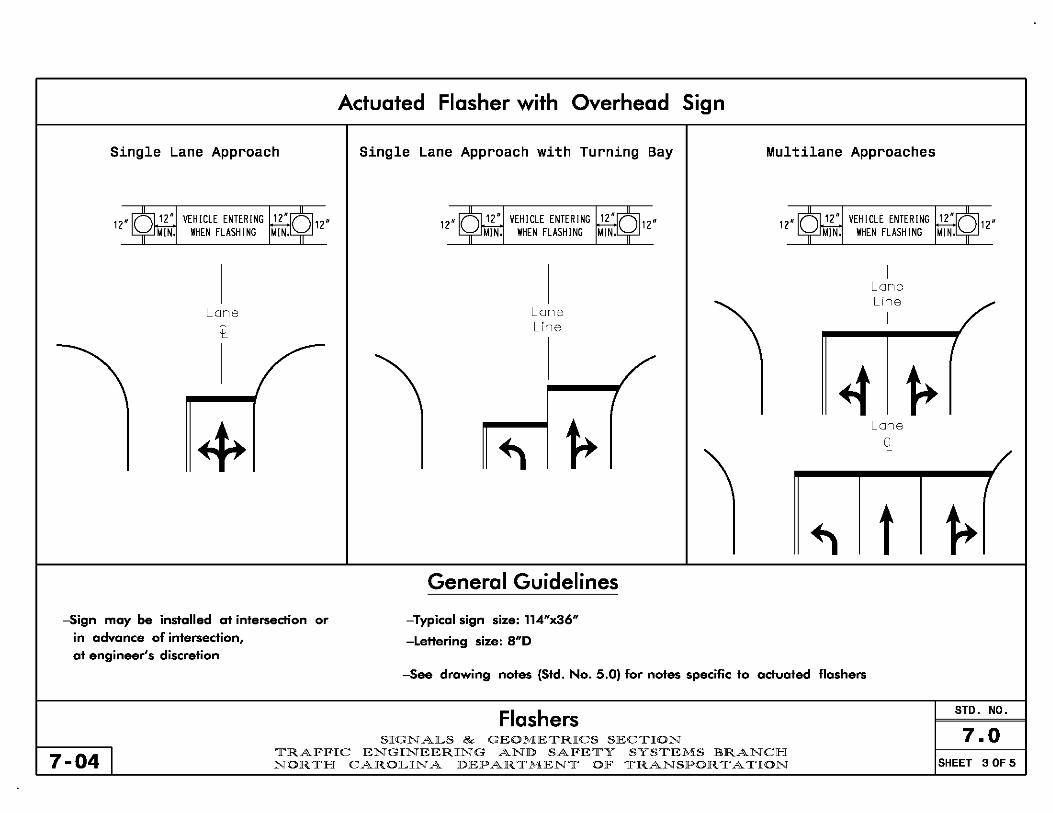
Actuated Flasher with Overhead Sign
Single Lane Approach Single Lane Approach with Turning Bay Multilane Approaches
12"~ VEHICLE ENTERING ~12" 12"~ VEHICLE ENTERING ~12" 12"~ VEHICLE ENTERING ~12" ~IN. WHEN FLASH I NG MIN. MIN. WHEN FLASHING MIN. MIN. WHEN FLASHING MIN.
I I
I
Lone LIne
Lone Lone I
Il Line
I 4 ~ + ~
Lone
~ Il I
~ t ~ General Guidelines
-Sign may be installed at intersectian ar -Typical sign size: 114"x36" in advance of intersection, -Lettering size: 8"0 at engineer's discretion
-See drawing nates (Std. Na. 5.0) far nates specific ta actuated flashers
Flashers STD. NO.
SIGNALS & GEOMETRICS SECTION 7.0 7-04 I TRAFFIC ENGINEERING AND SAFETY SYSTEMS BRANCH
NORTH CAROLINA DEPARTMENT OF TRANSPORTATION SHEET 3 OF 5
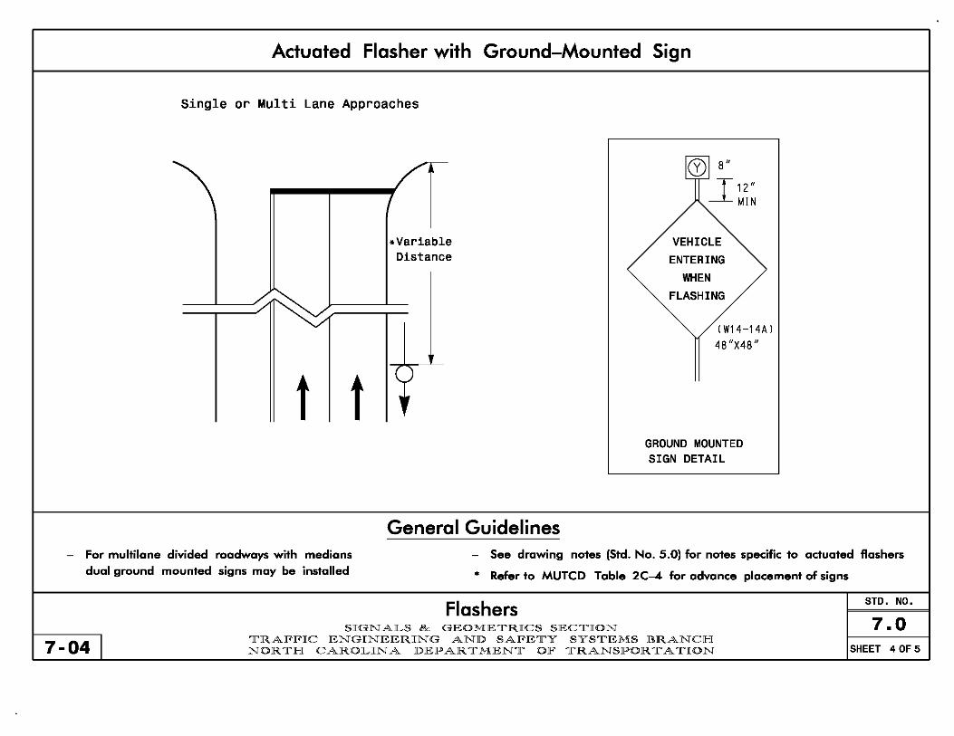
Actuated Flasher with Ground-Mounted Sign
Single or Multi Lane Approaches
/e- @ 8"
-.1 12 " MIN
.Variable VEHICLE Distance ENTERING
WHEN
~ FLASHING
/'
(W14-14A)
4S II X48 11
t t ()
•
GROUND MOUNTED SIGN DETAIL
General Guidelines - For multi lone divided roadwoys with medions - See drawing notes (Std. No. 5.0) for notes specific to actuated flashers
dual ground mounted signs may be installed • Refer to MUTCD Table 2C-4 for advance placement of signs
Flashers STD. NO.
SIGNALS & GEOMETRICS SECTION 7.0 7-04 I TRAFFIC ENGINEERING AND SAFETY SYSTEMS BRANCH
NORTH CAROLINA DEPARTMENT OF TRANSPORTATION SHEET 4 OF 5

Loop Placement for Actuated Flashers
Main Street Loop Placement Side Street Loop Placement (Single or Multilane)
'\ / - - - - - -
-=-J'
- - - -
OL -- - - - - -
OL "V
14 ~I L2
D
D + Design Speed D mph (km/hr) ft (m)
40 (64) 250 (75) 45 (72) 300 (90) Ll
50 (80) 355 (110) 0 55 (88) 420 ( 130)
L = 6ft X 6ft (1.8m X 1 . 8m) • Presence loop
L1 = 6ft X 6ft (1.8m X 1 . 8m) • Presence loop (Loop L 1 is optional)
L2 = 6ft X 40ft To 60ft (1.8m X 12.0) Quadruple loop
Flashers STD. NO.
SIGNALS & GEOMETRICS SECTION 7.0 11-061
TRAFFIC ENGINEERING AND SAFETY SYSTEMS BRANCH NORTH CAROLINA DEPARTMENT OF TRANSPORTATION SHEET 5 OF 5

Sign No.
R1 -1
R1 -2
R3-1 R3-2
R3-3
R3-4
7-04l
Description
"STOP" Sign
"YIELD" Sign
No Right Turn Sign No Left Turn Sign
"NO TURNS" Sign
No U Turn Sign
Graphic
~ V
Sign No.
R3-Sa
R3-SL R3-SR
R3-6L
R3-6R
R3-18
R8-8
Description
Through Arrow "ONLY" Sign
Left Arrow "ONLY" Sign Right Arrow "ONLY" Sign
Combined Through and Left Arrow Sign Combined Through and Right Arrow Sign
No U-Turn/No Left Turn Sign
"DO NOT STOP ON TRACKS" Sign
Commonly Used Signs SIGNALS & GEOMETRICS SECTION
TRAFFIC ENGINEERING AND SAFETY SYSTEMS BRANCH NORTH CAROLINA DEPARTMENT OF TRANSPORTATION
Graphic
[!J [~]
[[1]
[~ DO NOT
STOP ON
TRACKS
STD. NO.
8.0 SHEET 1 OF 2

Sign No. Description
R10-6
R10-7
R10-10L R10-10R
"STOP HERE ON RED" Sign
"DO NOT BLOCK INTERSECTION" Sign
"LEFT TURN SIGNAL" Sign "RIGHT TURN SIGNAL" Sign
R1 0 -11 "NO TURN ON RED" • Sign R10-11a "NO TURN ON RED" Sign
R1 0 -12
R10-13
"LEFT TURN YIELD ON GREEN" • Sign
"EMERGENCY SIGNAL" Sign
Graphic
STOP HERE ON
RED ;
DO NOT BLOCK INTERSEcnON
LEFT TURN
SIGNAL
NO TURN
ON RED • ifF! TURN
YIELD ON GREEN •
EMERGENCY SIGNAL
Sign No. Description
R10-15
R10-16
R10-21
W25-2
"TURNING TRAFFIC MUST YIELD TO PEDESTRIANS" Sign
"U-TURN YIELD TO RIGHT TURN" Sign For usage. see MUTCD Sect. 28.45, Page 28-43
"LEFT TURN SIGNAL YIELD ON GREEN" • Sign
Dual Turn Arrows Sign
Dual Turn and Through Arrows Sign
"ONCOMING TRAFIC MAY HAVE EXTENDED GREEN" Sign For usage, see MUTCD Sect. 2C39, Page 2C-20
Commonly Used Signs SIGNALS & GEOMETRICS SECTION
7-04 I TRAFFIC ENGINEERING AND SAFETY SYSTEMS BRANCH NORTH CAROLINA DEPARTMENT OF TRANSPORTATION
Graphic
TURNING TRAFFIC
MUST YIELD TO
PEDESTRIANS
U-TURN YIELD
TO RIGHT TURN
LEFT TURN SIGNAL
YIELD ON GREEN • I~ ffi O~~~~G~ MAYHAYE EXTENDED
GREEN
STD. NO.
8.0 SHEET 2 OF 2

1) In general, lane-use control signs are not required when a vehicle must shift into a turning bay to make a turning movement (Example 1).
2) In general, lane-use control signs should be used when:
7-04
A) Lane geometries allow a through movement, but a mandatory turn is required (Examples 2 and 3). B) A lane without a turn bay ends abruptly (Example 4).
Example 1 Example 2
ut!tlt\\L [~ [C]
t t
Example 3 Example 4
Application of Lane-Use Control Signs SIGNALS & GEOMETRICS SECTION
TRAlFlFIC ENGINEERING AND SAlFETY SYSTEMS BRANCH NORTH CAROLINA DEPARTMENT OlF TRANSPORTATION
STD. NO.
8.1 SHEET 1 OF 1

7-04
CASE 1 CASE 2 Locate Crosswalks from Center of Curve Connect Wheelchair Ramps
6'min (l.am) Bisector of
Angle/Curve
/---11
If---~
Reference: Roadway Standard Drawing 1205.07
Crosswalks SIGNALS & GEOMETRICS SECTION
TRAFFIC ENGINEERING AND SAFETY SYSTEMS BRANCH NORTH CAROLINA DEPARTMENT OF TRANSPORTATION
STD. NO.
9.0 SHEET 1 OF
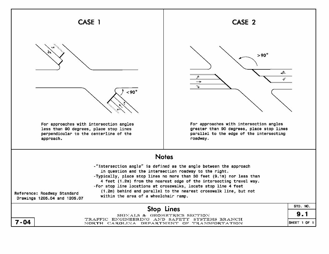
CASE 1
For approaches with intersection angles less than 90 degrees, place stop lines perpendicular to the centerline of the approach.
Notes
CASE 2
>90 0
:-\
For approaches with intersection angles greater than 90 degrees, place stop lines parallel to the edge of the intersecting roadway.
-"Intersection angle" is defined as the angle between the approach in question and the intersection roadway to the right.
-Typically, place stop lines no more than 30 feet (9.1m) nor less than 4 feet (1.2m) from the nearest edge of the intersecting travel way.
-For stop line locations at crosswalks, locate stop line 4 feet
Reference: Roadway Standard Drawings 1205.04 and 1205.07
(1.2m) behind and parallel to the nearest crosswalk line, but not within the area of a wheelchair ramp.
7-04
Stop Lines SIGNALS & GEOMETRICS SECTION
TRAFFIC ENGINEERING AND SAFETY SYSTEMS BRANCH NORTH CAROLINA DEPARTMENT OF TRANSPORTATION
STD. NO.
9.1 SHEET 1 OF 1

Distance "a"
---1r-??'II
/'
I
I
)
Clear Zone Distances for Pole Placement
Distance Distance "b"
Distance "c" -~.
~ Distance
~ Distance "a" •
Distance "a"
I f-I w
w I a:
f-
I <J)
w Ie \Ul
" ~--Distance "a"
Distance "b" MAIN STREET
Distance "a" Distance lib"
Design Distance from Distance Face Speed from EOP of Curb EOP
Face of Curb ft (m) MPH (km/h) ft (m) ft (m) ft (m)
~40 12 (3.S) 14 (4.0) (64)
4S-S0 16 (S.O) 18 (S.S) 7 10 (72-80) (2.0) (3.0)
~SS 22 (6.S) 22 (6.S) (88)
Distance "e"
Side St. Distance from Speed Face of Curb
MPH ft (m)
<40 7 (2.0) 4S-S0 7 (2.0) ~SS 10 (3.0) ~40 7 (2.0)
4S-S0 10 (3.0) ~SS 12 (4.S) :-:;40 7 (2.0)
4S-S0 10 (3.0) ~SS 12 (3.S)
Distance from EOP ft (m)
7 (2.0) 7 (2.0)
12 (3.0) 7 (2.0)
12 (3.S) 14 (4.S) 7 (2.0)
12 (3.S) 14 (4.S)
~ Pole Placement Not Recommended
Note 1: When traffic signals are installed on high-speed facilities J the signal supports should be placed as far away from the roadway as practical.
Note 2: Painted islands should not be used for pole locations unless a method of protection is provided (such as a guardrail).
Distances are the desired minimum from the face of pole Reference: "Roadside Design Guide" 2002 AASHTO
7-04
Standard Pole Placement SIGNALS & GEOMETRICS SECTION
TRAlFlFIC ENGINEERING AND SAlFETY SYSTEMS BRANCH NORTH CAROLINA DEPARTMENT OlF TRANSPORTATION
STD. NO.
10.0 SHEET 1 OF 1

Survey Level With Rod Method
Step 1: Using a standard Survey Level and Level Rod: -Take elevation shots on high point of roadway (shot "A") and at proposed pole foundation centerline (Shot "B").
~ 5~ Shot 'A' Shot '8' (3~ ~ ;I;(~~~~~;~ :;;n. Rodpo2~o7~2i;yo, ~ ~~II ~
- Shot RB"
7 . Rod Reading for
---- .::: ~ Pole No.1
~6.92'
~ 6":: . - - -( -~ - - - - - - - - - - - - - - - - - Level Ho,izon'al Line 01 Sight
,;; 4~ Level' ~ (2":: •
B Proposed
Pole No. 1 Location {Required Shot}
Curb & Gutter Shot {Optionol Shot}
May be required in some instances
A High Point of
Roadway Surface {Required Shot}
Edge of Pavement shot {Optional Shot}
May be required in some instances
Find the elevation difference between the proposed foundation and the high point of the roadway
Proposed Pole No.2 Location
{Required Shot}
- Subtract the rod reading of Shot "A" from the rod reading of shot "B".
_~J~~====~======~=====~====~~==~==-~l~:~;/{;.:~~P~ I L I :::J f Pole No.2 Location
~+2f'~' A {Required Shot}
Proposed Pole No. 1 Location
{Required Shot}
7-04 I
B - A = Elevation Difference
{Elevation difference for Pole No.1:
Do not round u .. ( p) ElevatLon dLfference for Pole NO.2:
6.92'-4.62' = 2.72'-4.62' =
+2.3' -1 .9'
Determining Elevation Difference for Metal Poles SIGNALS & GEOMETRICS SECTION
TRAFFIC ENGINEERING AND SAFETY SYSTEMS BRANCH NORTH CAROLINA DEPARTMENT OF TRANSPORTATION
STD. NO.
10.1.1 SHEET 1 OF 2

Total Station ~nd Data Collector With Prism Rod Method Step 1: Using a Total Station and Data collector with Prism Rod:
- Take elevation shots on high point of roadway (shot "A") and at proposed pole foundation centerline (Shot "B").
P=_ _ _ _ _ _ _ _ T;~~~:~~ _________________ -~~ - - - - - - - - - - - - Instrument Height Horizontal Sight Line (~. :1~6~~ ~) ~- ~- =-- =-- =--~ ~ ----= ---= ---= ---= --= --=- --=---=--:: -:::::-:::-::::- ==- ==-,0:::-~ -===- -= ~ - - - - - - - - - - - - - - - - - - - - - - - - - ~h~t-~~R- - - - - - - - - - - - --
- --- --- --- - -- Ground EL.=103.28' \
B ~-----Sh-ot'B' G Sdho"A'03S' /1\ r roun EL.=l 1.
[
G",und EL. = 99.0S'
~--~C~U:rb~&~G~U~H.=r~S~hO:'====================~~~================~Ed~9~.~o~f~pa=~=m:.=nt~s~ho:,~----------~ High Point of
Proposed Pole No.2 Location
(Requkod Shot) !--- (Op,;onal Shot) Roadway Surface (Optional Shot) B May be required in (Required Shot) May be required in
Proposed some instances some instances
Pole No. 1 Location (Requked Shot)
Step 2: Find the elevation difference between Shot "A" and Shot "B" - Subtract the ground elevation of Shot "B" from the roadway elevation of shot "A".
Notice the difference in the equation when different survey methods are used. A positive number should reflect that you would add the elevation difference to the pole height, where a negative number would mean that you would subtract the elevation difference when determining the pole height. I
__ ~J~~~==~==========~========~====~~~~~-ll~:i',~/~~~~p~ I L I ] f Pole No.2 Location
B----~---------- + 2f·3' ~ (Requkod Shot)
~---------- A - B = Elevation Difference P"'posod
Pole No. 1 Location (Required Shot)
7-04 I
{Elevation
(Do not round up) Elevation
difference for Pole NO.1: 101.3B'-99.08' = +2.3' difference for Pole No.2: 101.38' -1 03.28' = -1.9'
Determining Elevation Difference for Metal Poles SIGNALS & GEOMETRICS SECTION
TRAFFIC ENGINEERING AND SAFETY SYSTEMS BRANCH NORTH CAROLINA DEPARTMENT OF TRANSPORTATION
STD. NO.
10.1.1 SHEET 2 OF 2
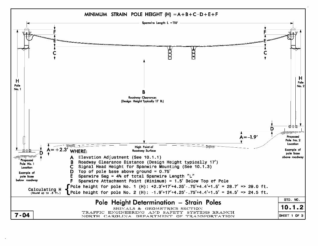
MINIMUM STRAIN POLE HEIGHT (H) =A+B+C-D+E+F
I" Spanwire Length L =110'
~ t t 1 'i 4 ;r F F 'i 4 ;r
\: :; -~--,
.~ :r --t ~ t ~ ~
;:: ,.. T C ,
H H Pole
Pole No.2 No.1
B Roadway Clearance:
(Design Height Typically 17 ft.)
t -¢ ~ =~ D
t=-1.9' f/ Proposed Pole No.2
---.l,1. Location
+2.3' WHERE: High Point of ~/-/'
Example of D',' Roadway Surface
pole base
?--il'ProJ;o.ed t A Elevation Adjustment (See 10. 1 . 1 ) above roadway
Pole No.1 B Roadway Clearance Distance (Design Height typically 17') Location C Signal Head Height for Spanwire Mounting (See 10.1.3)
Example of D Top of pole base above ground = 0.75' pole base E Spanwire Sag = 4% of total Spanwire Length "L"
below roadway F Spanwire Attachment Point (Minimum) = 1.5' Below TOp of Pole {pole height for pole No. 1 (H) : +2.3'+17'+4.25' - .75'+4.4'+1 .5' = 28.7' => 29.0 ft.
Calculating H Pole height for pole No. 2 (H) : -1 .9'+17'+4.25'- .75'+4.4'+1 .5' = 24.5' 24.5 ft. (ROund up to .5 ft.) =>
Pole Height Determination - Strain Poles STD. NO.
SIGNALS & GEOMETRICS SECTION 10.1.2 7-04 I TRAFFIC ENGINEERING AND SAFETY SYSTEMS BRANCH
NORTH CAROLINA DEPARTMENT OF TRANSPORTATION SHEET 1 OF 3

MAST ARM ATTACHMENT HEIGHT (H1) =A+8+C-D H1+F c-r-------,- MAST ARM POLE HEIGHT (H2) =
:Il~~~~~~~~~~~n~c~~~.~~ ~QO~======~~~~~I!I ~ '---, lbIl '---, WI. c tIj J:f: "T-
H2 Pole No.1
Hl Pole No.1
• ~~:::;-nD A + 2 ... "''''P",p ... d
Pole No.1 Location
Example of pole base
below roadway
EXAMPLES:
t tvHERE: A B C D F
{Mast
Calculating H1 (Round up to .1 ft.) Mast
. {pOle Calculahng H2 (ROund up to .5 ft.) Pole
7-04 I
B Roadway Clearance:
(Design Height Typically 17 ft.)
High Point of Roadway Surlace
Elevation Adjustment - (See 10.1.1) Roadway Clearance Distance (Design Height typically 17') Y2 Signal Head Height for Mast Arm Mounting (See 10.1.3) Top of Pole base above ground = 0.75' ~ Arm Attachment Point to Top of Pole = 2'
A=-1.9'
•
Arm attachment height for pole No. 1 (H1) : +2.3'+17'+ (4.67' /2) - .75' = 20.885' Arm attachment height for pole No. 2 (H1) : -1 .9'+17'+ (4.67' /2) - .75' height for pole No. 1 (H2) : 20.9'+2' = 22.9' => 23.0 ft. height for pole No. 2 (H2) : 16.7'+2' = 18.7' => 19.0 ft.
Pole Height Determination - Straight Mast Arms SIGNALS & GEOMETRICS SECTION
TRAFFIC ENGINEERING AND SAFETY SYSTEMS BRANCH NORTH CAROLINA DEPARTMENT OF TRANSPORTATION
= 16.685'
~ D t
=>
=>
Hl Pole No.2
H2 Pole No.2
~,;i< Proposed
Pole No.2 Location
Example of pole base
above roadway
20.9 ft. 16.7 ft.
STD. NO.
10.1.2 SHEET 2 OF 3

MAST ARM ATTACHMENT HEIGHT (H1) =A+8+C-D-E MAST ARM POLE HEIGHT (H2) = H1+F
rJ rEl1 II ,!J51 • ~ § 0 ~~~LLd;=;;=I=~~'llcbJJmf~it~=1tti -, i = t=========~~ r= T'
Arched arms are attached at a lower point on the pole upright -'-------------------------'?-~__;c3~/'f{-t/·1 1 than straight arms are. This situation can pose a potential --~
H2 Pole No.1
Hl Pole No.1
clearance problem for a vehicle if the structure is close to the edge of the travelway. but this can be addressed 1n the design of the structure.
When a metal pole with arched arms will be 6 ft. or closer to the edge of the travelway, provide the following information on the loading diagrams: a) Provide the horizontal distance from the ~ of the proposed
pole to the edge of the travelway. b) Provide the elevation difference between the edge of the
travelway and the ground elevation at the proposed foundation.
With this information, the pole manufacturer can modify the rake angle or slope of the arm to ensure that the minimum roadway clearance is met at a specific point from the pole.
B Roadway Clearance:
(Design Height Typically 17 ft.)
I Crt~e~ t -'-;=<~<=;'-nb~ "'== A + 2 .3'
. 3vil"Pro;o.ed
Pole No.1 Location
f t t .Provl~e WHERE:
High Point of Roadway Surface
Example of pole base
below roadway
EXAMPLES:
elevation difference iH,;6' A Elevation Adjustment (See 10.1.1)
B Roadway Clearance Distance (Design Height typically 17') C t2 Signal Head Height for Mast Arm Mounting (See 10.1.3) D Top of pole base above ground = 0.75' E Nominal Rise in Mast Arm = 5' F ~ Arm Attachment Point to Top of Pole = 2'
A=-1.9' t
~ D f
15.885'
H2 Hl Pole
No.2 Pole No.2
=>
)--
Proposed Pole No.2
Location
Example of pole base
above roadway
15.9 ft. {
Mast Arm attachment height for pole No. Calculating H1
(Round up to . t ft.) Mast Arm attachment height for pole No. 1 (H1): +2.3'+17'+(4.67'/2)-.75'-5.0' =
2 (H1): -1.9'+17'+(4.67'/2)-.75'-5.0' = 11 .685' => 11.7 ft.
{Pole height for pole No.1 (H2):
Calculating H2 (ROund up to .5 ft.) Pole height for pole No. 2 (H2):
15.9'+2' 11 .7'+2'
= 17.9' => 18.0 ft. = 13. 7' => 14.0 ft.
7-04 I
Pole Height Determination - Curved / Arched Mast Arms SIGNALS & GEOMETRICS SECTION
TRAFFIC ENGINEERING AND SAFETY SYSTEMS BRANCH NORTH CAROLINA DEPARTMENT OF TRANSPORTATION
STD. NO.
10.1.2 SHEET 3 OF 3

LOADING SCHEDULE FOR STRAIN POLES LOADING SCHEDULE FOR MAST ARM POLES
DESCRIPTION AREA SIZE WEIGHT DESCRIPTION AREA SIZE WEIGHT
SIGNAL HEAD 2SS W SIGNAL HEAD 25.5" W 12"-3 SECTION-WITH BACKPLATE. HANGER. AND 9.2 S.F. x S6 LBS 9.3 S.F. x 60 LBS BALANCE ADJUSTER 52.0" L 12"-3 SECTION-WITH BACKPLATE AND ASTRO-BRAG S2S L
SIGNAL HEAD 42.0" W SIGNAL HEAD 42.0" W 12"-4 SECTION (T-TYPE1-WITH BACKPLATE. 16.3 S. F. x 73 LBS 12"-4 SECTION IT-TYPE I-WITH BACKPLATE AND 16.3 S.F. x 90 LBS HANGER. AND BALANCE ADJUSTER 56.0" L ASTRD-BRAC 56.0" L
SIGNAL HEAD 2SS W SIGNAL HEAD 2S.S" W 12"-4 SECTION (VERTICAL1-WITH BACKPLATE. 11.6 S. F. x 69 LBS 12"-4 SECTION IVERTICALI-WITH BACKPLATE AND 11. 7 S.F. x 74 LBS HANGER. AND BALANCE ADJUSTER 65.5" L ASTRO-BRAG 66.0" L
SIGNAL HEAD 42.0" W SIGNAL HEAD 42.0" W 12"-S SECTION-WITH BACKPLATE. HANGER. 16.3 S. F. x 89 LBS 12"-5 SECTION-WITH 8ACKPLATE AND ASTRO-BRAC 16.3 S.F. x 103 LBS AND BALANCE ADJUSTER 56.0" L 56.0" L
SIGNAL HEAD 22.0" W SIGNAL HEAD 22.0" W 8"-3 SECTION-WITH 8ACKPLATE. HANGER. 6.3 S.F. x 41 LBS 8"-3 SECTION-WITH BACKPLATE AND ASTRD-8RAC 6.4 S.F. x 43 LBS AND BALANCE ADJUSTER 41.5" L 42.0" L
SIGNAL HEAD 22.0" W SIGNAL HEAD 22.0" W 8"-4 SECTION IVERTICALI-WITH BACKPLATE. 7.9 S.F. x 49 LBS 8"-4 SECTION IVERTICALl-WITH BACKPLATE AND 7.9 S.F. x 53.5 LBS HANGER. AND BALANCE ADJUSTER 51.5" L ASTRD-BRAC 52.0" L
SIGNAL HEAD 35.0" W SIGNAL HEAD 35.0" W 8"-5 SECTION-WITH BACKPLATE. HANGER. 10.6 S.F. x 62 LBS 8"-5 SECTION-WITH BACKPLATE AND ASTRD-BRAC 10.6 S.F. x 75 LBS AND BALANCE ADJUSTER 43.5" L 43.5" L
SIGN 24.0" W SIGN 24.0" W WITH HANGER 5.0 S.F. x 11 LBS RIGID MOUNTED WITH ASTRD-SIGN-BRAC 5.0 S.F. x 11 LBS
30.0" L 30.0" L
SIGN 30.0" W SIGN 30.0" W WITH HANGER 7.5 S.F. x 14 LBS RIGID MOUNTED WITH ASTRD-SIGN-BRAC 7.5 S.F. x 14 LBS
36.0" L 36.0" L
SIGN. LED BLANK OUT 24.0" W SIGN. LED BLANKDUT 24.0" W WITH HANGER 6.0 S.F. x 110 LBS WITH HANGER 6.0 S.F. x 110 LBS
36.0" L 36.0" L
Loading Schedules For Metal Poles STD. NO.
SIGNALS & GEOMETRICS SECTION 10.1.3 7-04 I
TRAFFIC ENGINEERING AND SAFETY SYSTEMS BRANCH NORTH CAROLINA DEPARTMENT OF TRANSPORTATION SHEET 1 OF 1

7-04 I
Typical Count Diagram Complete Traffic Counts
If a "naan" (between 10:30am and 2 :30pm) peak accurs, shaw in this fashian:
COUNTS
Type or duration of counting 16 Hour Counts ____ July 13 & 14,1999
Date of counting-----SR 1223
1 3920 1
PEAKS
1 AM 1
QD 7:30am 4:30pm
PEAKS
~11:30am -QD 4:30pm -
- 8:30am - 5:30pm
1 23 1 211 ~L\ 552 * 1 51 1 am peak hour traffic
1'---:3'--4---'1 ( 16 )..-/ T '---( 48 ) 1 54 ~ for this movement
( 22 ) 1 124 1 ( 42.) pm peak hour traffic .. \: for this movement
,----_--, ( 89 ) 601 * * 1 759 1 1 853 1 * .-------,
US 74 118,227 E 8002 -- ( 713 ) ( 689 ) -- 8501 18,015~ US 74
558 1 11 3 1 ;::* ADT for this leg Total of all ~ t --==-vehicles for the ~ '---1 -----'1 ( 72 ) 1 1
350
12:30pm 5:30pm
count period for . 45 . 1 51 I, . 24 .
this movement ( 60 ) GDM~2~5~1 6 1 ( 32 )
,--------------' ( ) 605 I 109* ( 12)
*Calculated by adding 16 hour totals for all movements in transit over this leg:
If data on three 76 8501 + 250 + 601 + peaks (am, noon, pm) is 1 3728 1 desired, show in this foshion
552 + 8002 + 109 = 18,015
Elm Street (Movements shown with asterisk)
Traffic Counts STD. NO.
SIGNALS & GEOMETRICS SECTION 11.0 TRAFFIC ENGINEERING AND SAFETY SYSTEMS BRANCH NORTH CAROLINA DEPARTMENT OF TRANSPORTATION SHEET 1 OF 3
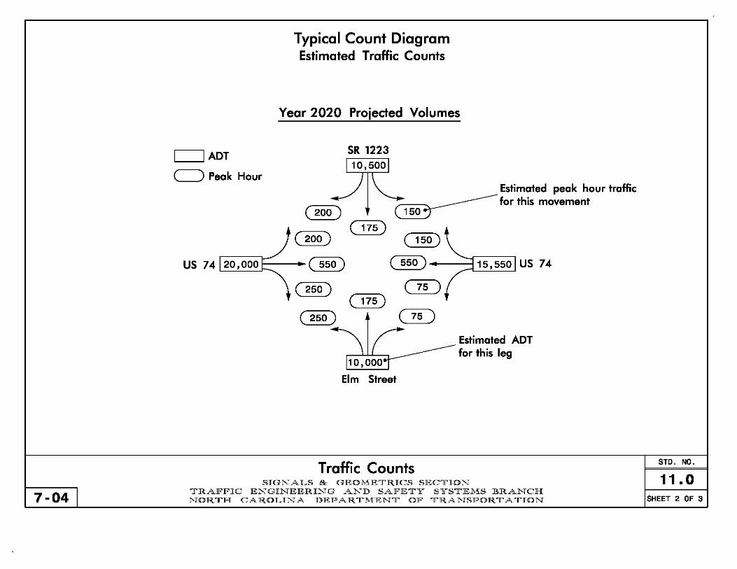
7-04 I
L-I -----,I ADT
c=) Peak Hour
Typical Count Diagram Estimated Traffic Counts
Year 2020 Projected Volumes
SR 1223
110,5001
) \ Estimated peak hour traffic ---:-::c=.-/-.., ~ ___________ for this movement (200) ~
t ( 175) .-/ (200) ( 150)
US 74 120,000 1 • ( 550 ) ( 550 ) -~::c!1~5~, 5~5o~1 US 74
~ (250) ( 75 ) t ( 175)
( 250) ( 75 )
\( 110,000
Elm Street
Traffic Counts
Estimated ADT for this leg
SIGNALS & GEOMETRICS SECTION TRAFFIC ENGINEERING AND SAFETY SYSTEMS BRANCH NORTH CAROLINA DEPARTMENT OF TRANSPORTATION
STO. NO.
11.0 SHEET 2 OF 3

Conversion from Estimated ADT to Estimated DDHV - Example GIVEN 1 Project Letting Date = 2000 STEP 11 Interpolate to find 2005 ADT. STEP 21 Convert to OOHV: (AOT) (OHV) (0) = OOHV.
Design Year=Letting Date+5 years=2005 For the north leg, 55 + (92·55)(9/20) = 72 For the north leg, (7200)(.10)(.60) = 432 D=60% DHV=10% ADT in hundreds 55 72 2005 ADT in hundreds 432 DDHV (velvhr)
- 1996 92 2016
11 19 15/ ~25 90/ ~50
160 lIi/ ~32
202 205 260 1230 1560 261
13~ /47
331
~ / ~ / - - 17 61 102 366 22 78
@ 85 110 660 -142
STEP 31 Determine through volumes by subtracting STEP 41 Complete count diagram. NOTESI turning volume from total volume.
-ADT = Average Daily Traffic For the north leg, 432 . 90 - 150 = 192
~ -DHV = Design Hour Volume
~t~GID -DDHV = Directional Design Hour Volume GD GID -0 = Directional Split (ill)
~ OD OID GID ~ GD GID -Use the highest directional split for 120 500 (1038) (1044) 26 0001 each movement. Do not attempt to
(1038) (1044) determine the direction of the peak flow .. .. \ f GID (366) for both the morning and afternoon
OID GID (ill) peak hours.
OID ('''~''') 0ID~lr366) -Because of the uncertainty of the data, a peak hour factor of 1.0 should be used when these peak hour volumes are used
11 000 for analysis.
Traffic Counts STD. NO.
SIGNALS & GEOMETRICS SECTION 11.0 7-04 I TRAFFIC ENGINEERING AND SAFETY SYSTEMS BRANCH
NORTH CAROLINA DEPARTMENT OF TRANSPORTATION SHEET 3 OF 3

7-04 I
Recommended Treatment fOr TUrn Lones
Symmetrical Widening A
I I I Variable II' Storoge • I ~D , ~\ Length *; T
'. ~ I \~~- =-- -- ---= - - - -:. - - - - - - - --(\\SSIS <t
'-~~==-::"::"::"'::"::'=:":":":"=:":":":"::..:=l::":"::"::":===o.-=-=-=-~-,- - - - - --
·1 I· A
A
Minimum Desirable Des i gn Speed Ppsted Speed Dsee I erat i on Osee I erato ion
Bay Taper Length
(T) Approach / Departure Taper (A)
(mph) (rrph) Length (D) Length (D)
30 '" 25 1 00' 150' 75' A = WS160 (IF S '" 40 MPH)
35 1 00' 150' 75' A = WS (IF S > 40 MPH)
40 35 150' 200' 1 00' S - Des i gn Speed
W = Width of Loteral Shift 45 40 150' 250' 100'
~----------~----------~----------~----------~--------~. Storage length for waiting 50
55
60
45 150' 300'
50 200' 500'
55 250' 57·5'
10Q'
150'
200'
vehicles should be calculated based on the latest version of the Highway Capacity Manual or Pol icy on Street and Driveway Access to North Carol ina Highways.
From PolicJ on Street and DrivewaJ Access to Nort Carolina Hig waJs
Geometries - Turn Lanes SIGNALS & GEOMETRICS SECTION
TRAFFIC ENGINEERING AND SAFETY SYSTEMS BRANCH NORTH CAROLINA DEPARTMENT OF TRANSPORTATION
STD. NO.
12.0 SHEET 1 OF 2

7-04 1
Recommended Treatment for Turn Lones
Pocket Lones , ,
, , ,
-------------------------------------------)\ ----------------~~--------,
------~----------------------~-------, ~-------------------------
~
- - - - - - ['- - -T- - - ~ - - - - - - - - - - - - - - - - - - - - -~ - - - - - - - '.,
I : I I Var'abl. I~ D • • Storage LenQth • ~
, , , , , ,
Near Side Widening
2/3 A • I T. I I : , , , , , , I T. I 2/3 A • I
~----------------------------------~
\~_... 3' ..v ;c:c \ , \
~~==~~~~vC-, ,~====~~~~~-
II. 2/3 A .1. D .1.var,abl·.I'" (' l.var'abl·.I. ·1· . i D 2/3 A
I Storage 1 Storage I
I---____ -'A'----___ ~~ Length I I Length 1---____ -"--____ ---1 I I' , I
A I I
All values to be determined using the table on the previous page.
From Polic) on Street and Drivewa) Access to Nort Carolina Hig wa)s
Geometries - Turn Lanes SIGNALS & GEOMETRICS SECTION
TRAFFIC ENGINEERING AND SAFETY SYSTEMS BRANCH NORTH CAROLINA DEPARTMENT OF TRANSPORTATION
STD. NO.
12.0 SHEET 2 OF 2

2070L Preemption Chart
",,' " ""'"'" '"', ,"",." " '", """,,,," ... "~:~:':"""". interval. This interval will use Dwell Min. Time below. 2070L EV PREEMPTION Selecting 255 sec. green indicates dwell (hold) phase. Clearance times for dwell (hold) phase. Using 0.0 sec. FUNCTION PRE 3 PRE 4 PRE 5 PRE 6
for each will allow controller to use times set in nor~~ Interval 1 - Dwell Green 255 255 255 255 operation.
Interval 1 - Dwell Yellow 0.0* 0.0* 0.0* 0.0* Amount of time signal is in exit phase before preemption~
Interval 1 - Dwell Red 0.0* 0.0* 0.0* 0.0* ends. Select 0 for controller to return to normal operation after preemption. Select 1 to designate an exit phase. Interval5 - Exit Green 1 1 1 1
Clearance time not used when Interval 5 is exit interval. { Interval5 - Yellow 0.0 0.0 0.0 0.0
Delay time after preempt call is received before going Interval5 - Red 0.0 0.0 0.0 0.0
to preempt phase. Usually 0.0 sec. for Opticom systems; -.. Delay Time 0.0 0.0 0.0 0.0 may need delay for pushbutton locations.
Min Green Before Pre 1 1 1 1
"",," """ ""' , .. ,," ,,, '"'~"' ",,' ' '''''/) Ped Clear Before Pre 0 0 0 0 transitioning into preempt phase. Usually 1 sec., so as
Yellow Clear Before Pre 0.0* 0.0* 0.0* 0.0* to begin preemption sequence immediately (0 sec. will default to normal minimum green time). Red Clear Before Pre 0.0* 0.0* 0.0* 0.0*
Time provided to display Flashing "DON'T WALK" for pedestrians Dwell Min Time 10 7 10 7 to clear intersection before beginning preemption sequence.
Enable Backup Protection YIN YIN YIN YIN Clearance times provided to clear current phase before Ped Clear Through Yellow YIN YIN YIN YIN transitioning into preemption. Using 0.0 sec. for each
Preempt Extend * * will allow controller to use times set in normal operation. 2 2 2 2
Minimum time preemption dwell phase will run. Opticom * Time defaul1s to time used for phase during nonnaloperation
systems typically use the same time as the phase in normal * * Program Timing on Optical Detection Unit
operation. Minimum time for pushbutton locations needs to be based on trial runs (typically by the Division).
Select yes to clear to all red before going into preemption Notes: to prevent yellow trap. 1) For pushbutton operation,
use EV PRE 2. --------
"y" (for Yes) will time the "Ped Clear Before Pre" and "Yellow 2) For Opticom type operation:
~ Clear Before Pre" simultaneously, thereby reducing overall For 1 preempt, use EV PRE 3 clearance time needed before preemption. Select "N" to time "FOW" For 2 preempts, use EV PRE 3 and 5 and then yellow clear and red clear before going into preeempt. For 3 preempts, use EV PRE 3, 4, and 5 Time to extend preempt dwell phase after call is dropped For 4 preempts, use EV PRE 3, 4, 5, and 6 I I
(usually 2 sec.) Prevents the call from being dropped 3) Include corresponding regular phases ~VPRE3 I
accidentally. Typically used for Opticom systems. in phasing diagram I __ J.eJ!.:'"~ __ J
Emergency Vehicle Preemption STD. NO.
13.0 SIGNALS & GEOMETRICS SECTION
7-05 I TRAFFIC ENGINEERING AND SAFETY SYSTEMS BRANCH NORTH CAROLINA DEPARTMENT OF TRANSPORTATION SHEET 1 OF 2

NEMA Preemption Chart Delay time after preempt call is received before gOing~ NEMA EV PREEMPTION to preempt phase. Usually 0 sec. for Opticom systems. May need delay for pushbutton locations, typically FUNCTION PRE 3 PRE 4 PRE 5 PRE 6 Division will determine delay needed.
Delay Before Preempt 0 0 0 0 Time provided to display Flashing "DON'T WALK" for
• Ped Clear Before Preempt pedestrian to clear intersection before beginning - - - -preempt sequence. This time may be reduced if necessar~ Min. Green Before Preempt 1 1 1 1
'''',"' """ ""' .,'"',' ,,' '"'CO"' "", ,,'," ~~~~ Yellow Clear Before Preempt 4.0 4.0 4.0 4.0 transitioning into preempt phase. Usually 1 sec., so Red Clear Before Preempt as to begin preemption sequence immediately (0 sec. 1.0 1.0 1.0 1.0
will default to normal minimum green time). Preempt Dwell Min. Green 10 7 10 7 Highest yellow and highest red clear times needed to CI~ Yellow elr After Preempt 4.0 4.0 4.0 4.0 normal operation phases (may come from different phases). Minimum time preemption dwell phase will run. Opticom Red Clear After Preempt 1.0 1.0 1.0 1.0
systems typically use the same time as the phase in normal Ped Clear Through Yellow YIN YIN YIN YIN operation. Minimum time for pushbutton locations needs to
Preempt Extend * * 2.0 2.0 2.0 2.0 be based on trial runs (typically by the Division). Clearance times for dwell (hold) phase. Use clearance
* * Program Timing on Optical Detection Unit Notes:
times from corresponding normal phase (See Std. 5.2.2, Sheet 4) . 1) For pushbutton operation, use EV PRE 2. --------
Some NEMA controllers allow Ped Clear time and Yellow Clear 2) For Opticom type operation:
~ time Before Preempt to time simultaneously, while other brands For 1 preempt, use EV PRE 3 I I
I ~ I do not. If in doubt about type of equipment being used, select "N." For 2 preempts, use EV PRE 3 and 5 I I For 3 preempts, use EV PRE 3, 4, and 5 I I
Time to extend preempt dwell phase after call is dropped For 4 preempts, use EV PRE 3, 4, 5, and 6 I I (usually 2 sec.) Prevents the call from being dropped 3) Include corresponding regular phases ~EV PRE 3 I accidentally. Typically used for Opticom systems. in phasing diagram I __ J0!!"~ __ J
170 Preemption Chart
(See Above) 170 EV PREEMPTION Time needed for pedestrians to clear intersection ~
FUNCTION EVA EVB EVC Eva before going into preempt phase. Delay Before Preempt 0 0 0 0
(See Above) Ped. Clear Before Preempt - - - -
~ Min. Green Before Preempt 1.0 1.0 1.0 1.0 Preemption dwell phase minimum green (times after~ call is released). Clearance Time 7 7 7 7
(See Above) • Preempt Extend * * 2.0 2.0 2.0 2.0
** Program Timing on Optical Detection Unit
Emergency Vehicle Preemption STD. NO.
13.0 SIGNALS & GEOMETRICS SECTION
7-04 I TRAFFIC ENGINEERING AND SAFETY SYSTEMS BRANCH NORTH CAROLINA DEPARTMENT OF TRANSPORTATION SHEET 2 OF 2

NOTE: BLANKOUT SIGNS ARE NOT USED IN CONJUNCTION WITH "YIELD" SIGN CONTROLLED MOVEMENTS
7-04
Use of Signal Heads and Blankout Signs Permissive Only Displays
@
62
61
I f
I
\ f
\ 81 82 I
" .... / ---21
22
Track Clearance Display
Railroad Preemption SIGNALS & GEOMETRICS SECTION
® CD 12" ® ® CD 12"
(8 ® 81 21, 22
41, 42 61, 62
82
@ No Left Turn 8lankout Sign ® Yield Sign (R1-2) © "ONCOMING TRAFFIC MAY
HAVE EXTENDED GREEN" Sign (W25-2)
STD. NO.
13.1 TRAFFIC ENGINEERING AND SAFETY SYSTEMS BRANCH NORTH CAROLINA DEPARTMENT OF TRANSPORTATION SHEET 1 OF 10

7-04
Use of Signal Heads and Blankout Signs Protected IPermissive Displays
Track Clearance Display
I f
I I
62 \
~ \ ,81 82 f I , /
61 ---® ..
Railroad Preemption SIGNALS & GEOMETRICS SECTION
21 41 61 81
o ©
12"
® o © 42 62 82
® 12/1
22
@ No Right Turn Blankout Sign
® No Left Turn Blankout Sign
© "ONCOMING TRAFFIC MAY HAVE EXTENDED GREEN" Sign (W25-2)
121/
STD. NO.
13.1 TRAFFIC ENGINEERING AND SAFETY SYSTEMS BRANCH NORTH CAROLINA DEPARTMENT OF TRANSPORTATION SHEET 2 OF10

NOTE: BLANKOUT SIGNS ARE NOT USED IN CONJUNCTION WITH "RED ARROW" SIGNAL DISPLA YS
7-04
Use of Signal Heads and Blankout Signs Protected Only Displays
Track Clearance Display
I
I I 52
\31 81 82 I /
51 , / ~
11 51
21 42 41 71
22
@
® ® ® 12/1 @ 12"
8 ® 11 21, 22 31 41, 42 51 61, 62 71 81, 82
@ No Right Turn Blankout Sign
Railroad Preemption SIGNALS & GEOMETRICS SECTION
TRAFFIC ENGINEERING AND SAFETY SYSTEMS BRANCH NORTH CAROLINA DEPARTMENT OF TRANSPORTATION
STD. NO.
13.1 SHEET 3 OF 10

Use of Signal Heads and Blankout Signs Advance Signal Heads
Design Consideration: When active crossing warning devices consists only of flashers (no gates present) and there is room to store vehicles between the tracks and the intersection.
Advance signal faces should be located as near as practical to the stop line.
(With Adequate Storage)
4443
-- _. Advance signal heads should not block or
obstruct flashers on cantilever __ (_i_f_u_s_e_d_)_' ___ ,,~~-_->_:o_~l-_--I __ '--_~;--.., I Adequate storage space to hold at least one design vehicle (typically assumed to be 20').
NOTE: Based on engineering judgement, advance signal heads may be placed downstream (across) of the railroad tracks.
NOTE: When advance heads are used,--===============~~ ... ,~ consider visibly limiting the signal .~~-L~~~::::r-. heads for the approach from the railroad at the intersection.
7-04
Railroad Preemption SIGNALS & GEOMETRICS SECTION
TRAFFIC ENGINEERING AND SAFETY SYSTEMS BRANCH NORTH CAROLINA DEPARTMENT OF TRANSPORTATION
SIGNAL FACE I.O.
~12" ~8"
43,44
SIGN I.O. @ "STOP HERE ON REO" Sign (R1 0-6)
<ID "DO NOT STOP ON TRACKS" Sign (R8-8)
TABLE OF OPERATION PHASE
SIGNAL 0 0 R R F 2 4 R R L
FACE + + c p A 6 8 L R S
R E H
43;44 FY FY R R R
FY - 8" Flashing Yellow (See Note 125 in Section 5.01
STD. NO.
13.1 SHEET 4 OF 10
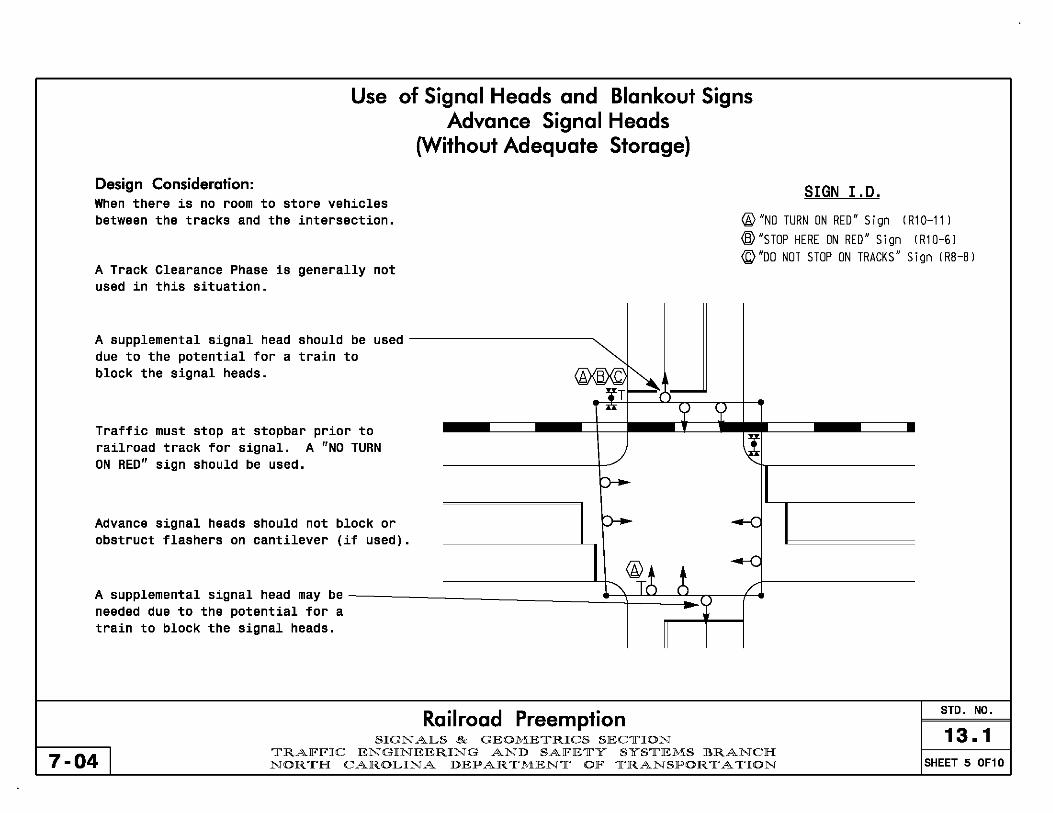
Use of Signal Heads and Blankout Signs Advance Signal Heads
(Without Adequate Storage)
Design Consideration: SIGN I.D. When there is no room to store vehicles between the tracks and the intersection. @"No TURN ON REO" Sign (R1 0-11 )
® "STOP HERE ON RED" Sign (R1 0-6)
(Q "00 NOT STOP ON TRACKS" Sign (RB-B) A Track Clearance Phase is generally not used in this situation.
A supplemental signal head should be used
'"'~ due to the potential for a train to block the signal heads. [A ~ =='l'T
n r> r> Traffic must stop at stopbar prior to
) ~ railroad track for signal. A "NO TURN ON RED" sign should be used.
P""- II Advance signal heads should not block or p-- --C obstruct flashers on cantilever (if used).
'\~~ ~ --C
A supplemental signal head may be /
needed due to the potential for a train to block the signal heads.
II
Railroad Preemption STD. NO.
SIGNALS & GEOMETRICS SECTION 13.1 7-04 I
TRAFFIC ENGINEERING AND SAFETY SYSTEMS BRANCH NORTH CAROLINA DEPARTMENT OF TRANSPORTATION SHEET 5 OF10

Track Clearance Phase Times Greenshield's Formula:
Track Clearance Green = 4+2(n/d), where: n = distance between stopbars Cantilevers, Gates, Flashers, and Railroad d = assumed length of design vehicle (20') Stopbars are usually located by Rail Division
$
n n n
~ n
Round Track Clearance Green time up n to the nearest whole number. n (i. e. 14.6 sec.~15 sec.)
./ "-
'\
Ii II
Railroad Preemption STD. NO.
SIGNALS & GEOMETRICS SECTION 13.1 7-04 I TRAFFIC ENGINEERING AND SAFETY SYSTEMS BRANCH
NORTH CAROLINA DEPARTMENT OF TRANSPORTATION SHEET 6 OF 10

2070L Preemption Chart Based on Greenshield's Formula (see Sheet 6). ------_ T~PiCally minimum is 10 seconds. 2070L RR PREEMPTION Tlmes for track clearance phase. Should be the same--__ _ 1
12
Used to designate this interval as the preemption dwell= .................••••••••••••••••••. ~ Interval! _ Track Clearance Yellow interval. This interval will use Dwell Min. Time below. Selecting 255 sec. green indicates dwell (hold) phase. Interval! - Track Clearance Red
3.7
1.8
255 for each will allow controller to use times set in
0.0*
Clearance times for dwell (hold) phase. Using 0.0 sec. ~ Interval2 - Dwell Green
normal operation. Interval2 - Dwell Yellow r---------------------+-----~~
Amount of time signal is in exit phase before preemption ~~-------___ ~ Interval2 - Dwell Red 0.0* ends. Select 0 for controller to return to normal operation -~ln-te-rv-a-I-5---Ex-it-G-~-e-n------+---1---1 after preemption. Select 1 to designate an exit phase. -
Clearance time not used when Interval 5 is exit interVal.---------__ {..! Interval5 - Yellow Interval 5 - Red Delay time after preempt call is received before going to
0.0
0.0 preemption sequence. Typically use 0 sec. -. Delay Time
"y" (for Yes) will time the "Ped Clear Before Pre" and "Yellow --~ Clear Before Pre" simultaneously. thereby reducing overall clearance time needed before preemption. Select "N" to time "FDW" and then yellow clear and red clear before going into preeempt.
Railroad Preemption SIGNALS & GEOMETRICS SECTION
Notes: :~ 1) Use Preemption 1 : ====cb : 2) Include corresponding, r,
regular phases in, , phasing diagram - _____ , _ RR DWELL ,
I __ -J.~!.:'"~ __ J
STD. NO.
13.1 7-05 I
TRAFFIC ENGINEERING AND SAFETY SYSTEMS BRANCH NORTH CAROLINA DEPARTMENT OF TRANSPORTATION SHEET 7 OF 10

NEMA (TS-l and TS-2) Preemption Chart
Delay time after preempt call is received before going into preempt sequence: Typically use 0 sec.
Time provided to display Flashing "DON'T WALK" for pedestrian to clear intersection before beginning preempt sequence. This time may be reduced if
NEMA RR PREEMPTION 1 necessary . . ,.,," "'" ,,., ""',' ,,' "",., "", ''''''" """~ Delay Before Preempt 0 transitioning into preempt phase. Usually 1 sec., so as to begin preemption sequence immediately (0 sec. Ped. Clear Before Preempt -will default to normal minimum green time).
Min. Green Before Preempt 1 Highest yellow and highest red clearance times
~ Yellow Clear Before Preempt -needed to clear normal operation phases (may
come from different phases). Red Clear Before Preempt -
Based on Greenshield's Formula (see Sheet 6). • Track Clearance Green -
Times for Track Clearance phase. Should be { Track Clearance Yellow -the same times as if the phase were used Track Clearance Red -in normal operation (See Std. 5.2.2, Sheet 4) •
---Preempt Dwell Min. Green -
Min Green Time for Dwell (hold) phase.
~ Yellow Clear After Preempt -Typically same as time used in normal
operation. Red Clear After Preempt -Yellow and Red Times of Dwell (hold) phase. Use Ped Clear Through Yellow YIN highest yellow and red times if more than 1 Dwell phase is used.
--------Some NEMA controllers allow Ped Clear time and Yellow Clear time Before Preempt to Notes:
~ time simultaneously, while other brands do 1) Use Preemption 1 I ~ I not. If in doubt about type of equipment 2) Include corresponding : ." I
being used, select "N." regular phases in I I phasing diagram- I RR DWELL I
I __ J.I?J!!"~ __ J
Railroad Preemption STD. NO.
SIGNALS & GEOMETRICS SECTION 13.1 7-04 I TRAlFlFIC ENGINEERING AND SAlFETY SYSTEMS BRANCH
NORTH CAROLINA DEPARTMENT OlF TRANSPORTATION SHEET B OF 10

170 Preemption Chart
170 RAILROAD PREEMPTION Delay time after preempt call is received before ~ I-----------------,-------j going into preempt sequence: Typically use a sec. ----. Delay Before Preempt 0
~--------------------~---------j
_____ -------- Track Clearance Green Based on Greenshield's Formula (see Sheet 6). '------------------'------'
NOTE: The Railroad preemption calls are immediate with 170 equipment. 170 Bi-Trans Software does not clear pedestrian times before entering Railroad Preemption. Ped displays go directly from a solid WALK to a solid DON'T WALK display and does not provide any clearance time (flashing DON'T WALK display).
Railroad Preemption SIGNALS & GEOMETRICS SECTION
STD. NO.
13.1 7-04 I
TRAFFIC ENGINEERING AND SAFETY SYSTEMS BRANCH NORTH CAROLINA DEPARTMENT OF TRANSPORTATION SHEET 9 OF 10
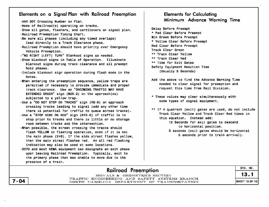
Elements on a Signal Plan with Railroad Preemption
-AAR DDT Crossing Number on Plan_ -Name of Railroad(s) operating on tracks_ -Show all gates, flashers, and cantilevers on signal plan_ -Railroad Preemption Timing Chart_ -Be sure all phases (including any timed overlaps)
lead directly to a Track Clearance phase_ -Railroad Preemption should have priority over Emergency
Vehicle Preemption. -"NO RIGHT (LEFT) TURN" Blankout signs as needed. -Show blankout signs in Table of Operation. Illuminate
blankout signs during track clearance and all preempt hold phases.
-Include blankout sign operation during flash mode in the Notes.
-When entering the preemption sequence, yellow traps are permitted if necessary to provide immediate and proper track clearance. Use an "ONCOMING TRAFFIC MAY HAVE EXTENDED GREEN" sign (W25-2) on the approach(es) subjected to a yellow trap.
-Use a "DO NOT STOP ON TRACKS" sign (RB-B) on approach crossing tracks leading to signal (add any other time there is potential for traffic to queue across tracks).
-Use a "STOP HERE ON RED" sign (R10-6) if traffic is to stop prior to tracks and there is little or no storage room between tracks and the intersection.
-When possible, the street crossing the tracks should flash YELLOW in flashing operation, even if it is not the main phase (2+6). If the side street flashes yellow, then the main street flashes red. An all red flashing indication may also be used at some locations.
-2070 and most NEMA equipment can designate an exit phase upon leaving Railroad Preemption. Typically, exit to the primary phase that was unable to move due to the presence of a train.
Elements for Calculating Minimum Advance Warning Time
Delay Before Preempt • Ped Clear Before Preempt Min Green Before Preempt • Yellow Clear Before Preempt Red Clear Before Preempt Track Clear Green •• Track Clear Yellow •• Track Clear Red •• Time for Exit Gates Safety Equipment Reaction Time
(Usually 5 Seconds)
Add the above to find the Advance Warning Time needed to clear signal for preemption and request this time from Rail Division.
• These values may clear simultaneously with some types of signal equipment.
•• If 4 quadrant (exit) gates are used, do not include Track Clear Yellow and Track Clear Red times in this equation. Instead add:
12 Seconds for exit gates to descend to horizontal position.
5 seconds (exit gates should be horizontal 5 seconds prior to train arrival).
Railroad Preemption STD. NO.
13.1 7-04 I
SIGNALS & GEOMETRICS SECTION TRAFFIC ENGINEERING AND SAFETY SYSTEMS BRANCH NORTH CAROLINA DEPARTMENT OF TRANSPORTATION SHEET 10 OF 10

Design Considerations The purpose of system detectors is to provide volume and occupancy information for dynamic traffic control.
More advanced equipment allows for independent control of multiple zones in the same system, so each system must be evaluated to determine its logical segments. (a.k.a. zones)
Subject to the noted limits, enough system detectors should be included to provide redundant detection of main and side street traffic in each zone of the system:
Main street detection should be provided in each direction at multiple intersections in each zone.
System Detector Limits - 2070 Systems:
Each master controller is limited to 64 system detectors. Each local controller is limited to 16 system detectors.
- NEMA TS-1 and TS-2 Systems: Each master controller is limited to 32 system detectors. Each local controller is limited to 8 system detectors.
- Other Considerations: Pole-mounted cabinets frequently have limited rack space for detectors, which may limit the number of system detectors. Keep some system detectors in reserve for future signal addition and/or Side street detection should be provided at
critical intersections in each zone and at additional locations when combined loops are possible and system detector limits are not compromised.
addition of system detectors based on field experience.
Design Engineer should consult with system timing group to determine ultimate system detector locations.
7-04 I
Closed Loop Signal Systems - General information SIGNALS & GEOMETRICS SECTION
TRAFFIC ENGINEERING AND SAFETY SYSTEMS BRANCH NORTH CAROLINA DEPARTMENT OF TRANSPORTATION
STD. NO.
14.0 SHEET 1 OF 1
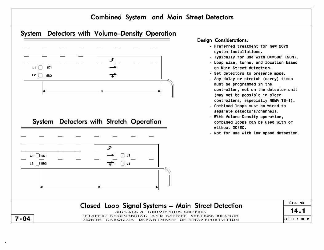
Combined System and Main Street Detectors
System Detectors with Volume-Density Operation Design Considerations:
- Preferred treatment for new 2070 - - - - - - - -
system installations_
j
I
- Typically for use with 0>=300' (90m). - - - - - Loop size, turns, and location based
L1 0 SDl - on Main Street detection. - - - - - - - -
Set detectors to presence mode. L2 0 T -SD2
I - Any delay or stretch (carry) times
I~ ~I must be programmed in the
D controller, not on the detector unit (may not be possible in older controllers, especially NEMA TS-1).
- Combined loops must be wired to separate detectors/channels.
- With Volume-Density operation, System Detectors with Stretch Operation combined loops can be used with or
without DC/EC. - Not for use with low speed detection.
- - - - - - - -
j - - - -
L1 0 SDl - o L3 - - - - - - - -
L2 0 SD2 T o L3
I. • 1 D
Closed Loop Signal Systems - Main Street Detection STD. NO.
SIGNALS & GEOMETRICS SECTION 14.1 7-04 I TRAlFlFIC ENGINEERING AND SAlFETY SYSTEMS BRANCH
NORTH CAROLINA DEPARTMENT OlF TRANSPORTATION SHEET 1 OF 2

Downstream Main Street System Detectors
Downstream System Detector Placement Design Considerations:
-Preferred for consistency at signals
J in existing systems with downstream
I_ -I system detectors, especially older
0 NEMA systems. -May also be appropriate in new
OS02 systems at locations with heavy
- - - - - - - - undetected turns from the side street o S01 to the main street (where side street
j system detectors are not appropriate). - - - - -Set detectors to presence mode. - -Locate downstream system detectors
- - - - - - - -
-V past the point where traffic has selected a lane while also avoiding
1 driveways.
-SD = 6ft X 6ft,(1.8m X 1.8m) Wired to separate channels
-D=50-250' (15m-75m) beyond intersection
Closed Loop Signal Systems - Main Street Detection STD. NO.
SIGNALS & GEOMETRICS SECTION 14.1 7-04 I TRAFFIC ENGINEERING AND SAFETY SYSTEMS BRANCH
NORTH CAROLINA DEPARTMENT OF TRANSPORTATION SHEET 2 OF 2
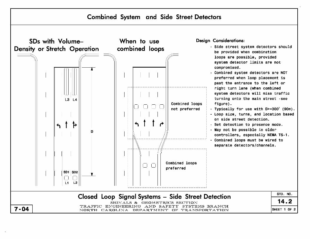
Combined System and Side Street Detectors
SDs with VolumeDensity or Stretch Operation
When to combined
use loops
Design Considerations: - Side street system detectors should
be provided when combination
I I L3 L4
I I
~ t ~ I I
I I
SDl I SD2
o 0 L 1 L2
7-04 I
o
~--- ------------------
I I I I
o 0 0 0 Combined loops not preferred
I I I
~ t t ,.
loops are possible, provided system detector limits are not compromised_
- Combined system detectors are NOT preferred when loop placement is past the entrance to the left or right turn lane (when combined system detectors will miss traffic turning onto the main street -see figure)_
- Typically for use with 0>=300' (90m)_ - Loop size, turns, and location based
on side street detection_ - Set detection to presence mode. - May not be possible in older
I .. \11 ................................................. . controllers, especially NEMA TS-l. Combined loops must be wired to separate detectors/channels.
I
o 0
I
Combined loops preferred
Closed Loop Signal Systems - Side Street Detection STD. NO.
14.2 SIGNALS & GEOMETRICS SECTION TRAlFlFIC ENGINEERING AND SAlFETY SYSTEMS BRANCH NORTH CAROLINA DEPARTMENT OlF TRANSPORTATION SHEET 1 OF 2

7-04 I
1
L 1 L2
1 1
~ t 1+ 1 1
S011 S02
00
Upstream Side Street - System Detectors
o
-so = 6ft X 6ft,(1.8m X 1.8m) Wired to separate channels
-0 = 300'-500', (90m-150m)
Design Considerations: - When combination loops are not
possible or not preferred, this treatment may be used at the critical intersection in each zone of new system installation.
- Set detectors to presence mode. - 0 should be chosen to ensure all
volume is counted before entering left or right turn lanes.
- If turn lane consideration makes 0 unreasonably large, consider placing a system detector in the turn lane (preferred) or using downstream main street system detectors at this location (less preferred)
Closed Loop Signal Systems - Side Street Detection STD. NO.
14.2 SIGNALS & GEOMETRICS SECTION TRAFFIC ENGINEERING AND SAFETY SYSTEMS BRANCH NORTH CAROLINA DEPARTMENT OF TRANSPORTATION SHEET 2 OF 2