Embed Size (px)
Citation preview

SIGE Internal GroovingGER---M type insert features a 3-D molded chipbreaker for cost effective chip controlInternal screw clamp toolholder provides excellent chip evacuation
GER---A type insert features an 8mm minimum cutting diameter with a 2 edge designNew PR1025 PVD coated carbide provides very stable machining and long tool life

◇ Consistent machining with our new micrograin carbide substrate and PVD-FS TiCN coating
◇ Long tool life
GER---M type
TiCN PVD Coated
Micro-grain Carbide Substrate
■ SIGE Advantages◇ Large chip pocket screw clamp toolholder design provides excellent chip evacuation
◇ Cost effective chip control from a 3-D molded chipbreaker on the new GER---M type insert ◇ An 8mm minimum cutting diameter with a 2 edge design on the GER---A type insert◇ New PR1025 PVD coated carbide
Large chip pocket
Screw Clamp Top Clamp
3.23.0 3.03.2
3.0 3.03.2
5.5
6.5
SIGE Insert and Toolholder Lineup
2
Insert
Shape
Ground chipbreaker 3-D molded chipbreaker Ground chipbreaker
DescriptionGER/L…A GER/L…B GER…CM GER…DM GER…EM GER/L…C GER/L…D GER/L…E
GER…AR GER…BR - - - GER…CR GER…DR -
Groove Width1.0 (0.04")
~
2.0 (0.08")
1.0 (0.04")
~
3.0 (0.12")
1.0
~
2.01.5
2.0
~
2.5
3.0
~
4.01.5 2.0
2.5
~
3.0
3.5
~
4.0
4.5
~
5.0
1.0
~
3.0
1.0
~
1.45
1.5
~
1.95
2.0
~
2.8
3.0
~
4.01.0
1.5
~
1.95
2.0
~
2.3
2.5
~
3.3
3.5
~
4.3
4.5
~
5.0
Available Groove
Depth (mm)
7
6
5
4
3
2
1
Toolholder
Minimum Cutting Dia. (mm) ø8mm (0.3") ø10 (0.4"),ø12 (0.5") ø14,ø16 ø20 ø25,ø32,ø40 ø14,ø16 ø20 ø25,ø32,ø40
Excellent Bar SIGER
/L…A-EH
SIGER
/L…B-EH
SIGER
/L…C-EH
SIGER
/L…D-EH SIGER
/L…E-EH SIGER
/L…C-EH
SIGER
/L…D-EH SIGER
/L…E-EH
Carbide Shank Bar SIGER
/L…A-WH
SIGER
/L…B-WH
- - - - - -
See P.3-P.5 for details.
4.5
2.5
4.5
3.2
2.52.5
6.5
5.5
4.54.5
2.5mm (0.10")
1.5mm (0.06")
2.5
GER---A type

Cutting time
Wea
r (m
m)
0.16
0.14
0.12
0.10
0.08
0.06
0.04
0.02
00 20 40 60 80 100
PR1025
Competitor D (PVD)
Competitor E (PVD)
■Comparison of chip evacuation (Minimum cutting dia. 8mm) ■Comparison of wear resistanceMaximum wear amount of front edge relief surface
[ Vc=328 sfm,doc=0.04",f =0.002 ipr,One side grooving, Wet, 4135 ](Internal evaluation)
Feed rate
Description
SCM415Evaluation
0.0008 in/rev
SIGER0808A-EHGER200-010A
PR1025
Comp C(Width .08 in)
Chipping
[ Vc=164 sfm, doc=0.05", Wet ](Internal evaluation)
■Comparison of chip evacuation (3-D molded chipbreaker GER---M)Feed rate
(in/rev)
Description
SCM415(Minimum Bore Dia.ø0.6" )Evaluation
0.001 0.002 0.003 0.004
SIGER1612C-EHGER300-020CM(PR1025) Good chip control
Comp A3mm (Width 3mm)
Insert fracture Unstable chip control and biting
Comp B3mm (Width 3mm)
Unstable chip control and biting
〔 Vc =328 sfm, ap=.079" , Wet 〕 (Internal evaluation)
Gro
ove
Dep
th
Minimum Cutting Dia. (in)
0.10in
ø0.15 ø0.3 ø0.5 ø0.8 ø1.4 ø1.6
0.20in
0.45in
VNGSIGE
SIGE
Wide applicable rangeKIGM-V
GIV
KIGBA
Groove width(inch)
0.04 0.04 0.04 0.04 0.04 0.04 0.04 0.04 0.06 0.04 0.04 0.06 0.11 0.01 0.060.12
0.12 0.16 0.16~ ~ ~ ~ ~ ~ ~ ~ ~ ~ ~ ~ ~ ~ ~ ~ ~ ~
0.08 0.08 0.08 0.08 0.08 0.12 0.12 0.16 0.20 0.12 0.13 0.16 0.20 0.1 0.19 0.16 0.20 0.20
Available Groove Depth (inch)
0.45 0.43
0.40
0.350.33
0.30
0.250.26 0.25 0.26
0.200.22
0.1750.18 0.17
0.15
0.100.10 0.09 0.10 0.09 0.09 0.09 0.11
0.0750.07 0.06
0.050.03 0.04
Minimum Cutting Dia. (inch) ø0.16 ø0.20 ø0.24 ø0.28 ø0.32ø0.39 ø0.47
ø0.55 ø0.63
ø0.79ø0.98 ø1.26 ø1.57
ø0.47ø0.55 ø0.63
ø0.79ø0.98 ø1.26 ø1.57
ø1.26 ø1.57 ø0.79 ø0.98 ø1.26 ø1.57
Toolholder VNG SIGE GIV KIGBA KIGM-V
■Applicable Range of Internal Grooving Tool
3

■ Insert grade selectionClassification of usage
: Continuous-Light Int. /1st Choice : Continuous-Light Int. /2nd Choice
l: Continuous / 1st Choice: Continuous / 2nd Choice
Cermet PVD Coated Carbide
TN6020 PR1025 GW15 KW10
P Carbon Steel / Alloy Steel
M Stainless Steel
K Cast Iron
N Non-ferrous Material
S Titanium Alloy
HHardened Material(~40HRC) ◦ ◦Hardened Material(40HRC~)
Workpiece Material
Recommended Insert Grade(Cutting Speed : sfm) f at Grooving (ipr)
Remark
f at Traversing (ipr)
Cermet PVD Coated Carbide doc at Traversing (inch)
TN60
20
PR10
25
KW10 GER/L
100~200-010A 100~200-100AR
GER/L 100~200-010B
100~200-100BR
GER/L 250~300-020B
Carbon Steel ☆ 150~275
★ 150~275 -
0.0004~0.0012 0.0008~0.0016 0.0008~0.0016
Coolant
0.0004~0.0012 0.0008~0.0016 0.0008~0.0016Max. 0.002 Max. 0.0020 Max. 0.004
Alloy Steel ☆ 150~275
★ 150~275 -
0.0004~0.0012 0.0008~0.0016 0.0008~0.00160.0004~0.0012 0.0008~0.0016 0.0008~0.0016Max. 0.002 Max. 0.002 Max. 0.004
Stainless Steel(SUS304) - ★ 150~275 -
0.0004~0.0012 0.01~0.03 0.01~0.030.0004~0.0012 0.01~0.03 0.01~0.03Max. 0.002 Max. 0.002 Max. 0.004
Cast Iron(FC FCD) - - ★ 150~275
0.0004~0.0012 0.0008~0.0016 0.0008~0.00160.0004~0.0012 0.0008~0.0016 0.0008~0.0016Max. 0.002 Max. 0.002 Max. 0.004
Aluminum - - ★ 150~350
0.0004~0.0012 0.0008~0.0016 0.0008~0.00160.0004~0.0012 0.0008~0.0016 0.0008~0.0016Max. 0.004 Max. 0.004 Max. 0.008
Brass - - ★ 150~350
0.0004~0.0012 0.0008~0.0016 0.0008~0.00160.0004~0.0012 0.0008~0.0016 0.0008~0.0016Max. 0.004 Max. 0.004 Max. 0.008
* Use PVD coated grade or carbide for traversing with edge width 1mm.(GER/L100-005A / 100-005B) : 1st Recommendtion : 2nd Recommendtion
◆ Recommended cutting conditions (Ground Chipbreaker : GER/L. . .A(R),GER/L. . .B(R))
4 KYOCERA Customer Service and Technical Assistance 800-823-7284 [email protected]

◆ Recommended cutting conditions (Ground Chipbreaker : GER/L. . .C(R),GER/L. . .D(R),GER/L. . .E)
Workpiece Material
Recommended Insert Grade(Cutting Speed : sfm) f at Grooving (ipr)
Remark
f at Traversing (ipr) doc at Traversing (inch)
Cermet PVD Coated CarbideGER/L
100~200-010C200-100CR
GER/L250~350-020C
250~300-150CR
TN60
20
PR10
25
GW
15
GER/L 100~145-010D
GER/L 150~195-010D
GER/L 200~280-020D
200-100DR
GER/L 300~400-020D
300-150DR
GER/L 100-010E
GER/L 150~195-010E
GER/L 200~225-010E
230-020EGER/L
250~330-020EGER/L
350~430-020EGER/L
450~500-020E
Carbon Steel ☆ 375~600
★ 200~
475-
0.0012~0.0031 0.0012~0.0031 0.0016~0.0035 0.0016~0.0035 0.002~0.0047 0.002~0.0047 0.002~0.0047
Coolant
0.0012~0.0031 0.0012~0.0031 0.0016~0.0035 0.0016~0.0035 0.002~0.004 0.002~0.004 0.002~0.004Max. 0.012 Max. 0.012 Max. 0.012 Max. 0.012 Max. 0.02 Max. 0.02 Max. 0.02
Alloy Steel ☆ 325 ~ 525
★ 200 ~
400-
0.0012~0.0028 0.0012~0.0028 0.0016~0.032 0.0016~0.032 0.002~0.004 0.002~0.004 0.002~0.0040.0012~0.004 0.03~0.1 0.0016~0.032 0.0016~0.032 0.002~0.004 0.002~0.004 0.002~0.004Max. 0.012 Max. 0.012 Max. 0.012 Max. 0.012 Max. 0.02 Max. 0.02 Max. 0.02
Stainless Steel(SUS304) ☆ 225 ~ 450
★ 200 ~
375-
0.0012~0.0028 0.0012~0.0028 0.0016~0.032 0.0016~0.032 0.002~0.004 0.002~0.004 0.002~0.0040.0012~0.004 0.0012~0.004 0.0016~0.032 0.0016~0.032 0.002~0.004 0.002~0.004 0.002~0.004Max. 0.012 Max. 0.012 Max. 0.012 Max. 0.012 Max. 0.02 Max. 0.5 Max. 0.02
Cast Iron(FC FCD) - -★
200 ~350
0.0012~0.0031 0.0012~0.0031 0.0016~0.0035 0.0016~0.0035 0.002~0.0047 0.002~0.0047 0.002~0.00470.0012~0.0031 0.0012~0.0031 0.0016~0.035 0.0016~0.035 0.002~0.004 0.002~0.004 0.002~0.004Max. 0.012 Max. 0.012 Max. 0.012 Max. 0.012 Max. 0.02 Max. 0.02 Max. 0.02
Aluminum - -★
500 ~1000
0.002~0.005 0.002~0.005 0.002~0.006 0.002~0.006 0.003~0.006 0.003~0.006 0.003~0.0060.002~0.005 0.002~0.005 0.002~0.006 0.002~0.006 0.003~0.006 0.003~0.006 0.003~0.006Max. 0.02 Max. 0.02 Max. 0.02 Max. 0.02 Max. 0.03 Max. 0.03 Max. 0.03
Brass - -★
350 ~825
0.002~0.005 0.002~0.005 0.002~0.006 0.002~0.006 0.003~0.006 0.003~0.006 0.003~0.0060.002~0.005 0.002~0.005 0.002~0.006 0.002~0.006 0.003~0.006 0.003~0.006 0.003~0.006Max. 0.02 Max. 0.02 Max. 0.02 Max. 0.02 Max. 0.03 Max. 0.03 Max. 0.03
* Use PVD coated grade or carbide for traversing with edge width 1mm.(GER/L100-010C / 100-010D / 100-010E) ★:1st Recommendtion ☆:2nd Recommendtion
◆ Recommended cutting conditions (3-D Molded Chipbreaker)
Workpiece Material
Recommended Insert Grade(Cutting Speed : sfm) f at Grooving (ipr)
Remark
f at Traversing (ipr)
Cermet PVD Coated Carbide doc at Traversing (inch)
TN60
20
PR10
25
GW
15
GER 150~ 200-010CM
GER 250~ 350-020CM
GER 150~ 200-010DM
GER 230~ 250-020DM
GER 300~ 400-020DM
GER 150~ 200-010EM
GER 250~ 300-020EM
GER 350~ 400-020EM
GER 450~ 500-020EM
Carbon Steel -★
200 ~525
-0.0012~0.004 0.0012~0.0047 0.0016~0.0047 0.002~0.0047 0.002~0.0047 0.002~0.0047
Coolant
0.0012~0.004 0.0012~0.004 0.0016~0.004 0.002~0.004 0.002~0.004 0.002~0.004Max. 0.04 Max. 0.06 Max. 0.06 Max. 0.06 Max. 0.06 Max. 0.06
Alloy Steel -★
200 ~475
-0.0012~0.004 0.0012~0.004 0.0016~0.0047 0.002~0.0047 0.002~0.0047 0.002~0.00470.0012~0.004 0.0012~0.004 0.0016~0.004 0.002~0.004 0.002~0.004 0.002~0.004Max. 0.04 Max. 0.06 Max. 0.06 Max. 0.06 Max. 0.06 Max. 0.06
Stainless Steel(SUS304) -★
200 ~375
-0.0012~0.0032 0.012~0.0032 0.0016~0.0032 0.002~0.004 0.002~0.004 0.002~0.0040.0012~0.004 0.0012~0.004 0.0016~0.004 0.002~0.004 0.002~0.004 0.002~0.004Max. 0.04 Max. 0.06 Max. 0.06 Max. 0.06 Max. 0.06 Max. 0.06
★:1st Recommendtion ☆:2nd Recommendtion
5

・Dimension B shows available grooving depth. ◦ : Standard Stock◦ : World Express
■ Applicable Insert
Shape
Right-handed inserts shown
Description
Dimensions (mm) Cermet PVD Coated Carbide
Applicable holderW
(mm)W(in)
B(max
depth)C rε A L H dø TN
6020
PR10
25
KW10
R L R L R L
2 Edge type
Ød
H
L
W±0.025
A2°
CB
rε rε
GER/L 100-005A 1.00 0.039
1.5 1.8
0.05
6.69 6.5 2.58 2.5
◦ ◦ ◦ ◦ ◦ ◦
SIGER/L…A-EH
120-005A 1.20 0.047 ◦ ◦ ◦ ◦ ◦ ◦
125-005A 1.25 0.049 ◦ ◦ ◦ ◦ ◦ ◦
150-010A 1.50 0.0590.1
◦ ◦ ◦ ◦ ◦ ◦
200-010A 2.00 0.079 ◦ ◦ ◦ ◦ ◦ ◦
GER/L 100-005B 1.00 0.039
2.2 2.6
0.05
8.46 8.2 3.18 2.7
◦ ◦ ◦ ◦ ◦ ◦
SIGER/L…B-EH
120-005B 1.20 0.047 ◦ ◦ ◦ ◦ ◦ ◦
125-005B 1.25 0.049 ◦ ◦ ◦ ◦ ◦ ◦
145-010B 1.45 0.057
0.1
◦ ◦ ◦ ◦ ◦ ◦
150-010B 1.50 0.059 ◦ ◦ ◦ ◦ ◦ ◦
200-010B 2.00 0.079 ◦ ◦ ◦ ◦ ◦ ◦
250-020B 2.50 0.0980.2
◦ ◦ ◦ ◦ ◦ ◦
300-020B 3.00 0.118 ◦ ◦ ◦ ◦ ◦ ◦
L
B
A
C
W±0.05
Ød
2°
Hrε rε
GER100-010CM~200-010CM
GER 150-010CM 1.50 0.059
2.5 2.7
0.1
5.8 11.48 4.05 2.8
◦
SIGER…C-EHSIGER/L…C-WH
200-010CM 2.00 0.079 ◦
250-020CM 2.50 0.098
0.2
◦
300-020CM 3.00 0.118 ◦
350-020CM 3.50 0.138 ◦
rε
2° A
W±0.05
L
H
CB
Ød
rε
GER150-010DM~200-010DM GER150-010EM~200-010EM
GER 150-010DM 1.50 0.059 3.0
4.8
0.1
6.8 16.44 5.05 3.4
◦
SIGER…D-EH
200-010DM 2.00 0.079
3.2
◦
230-020DM 2.30 0.091
0.2
◦
250-020DM 2.50 0.098 ◦
300-020DM 3.00 0.118
4.5
◦
A2°
W±0.05
B C
L Ød
Hrε rε
GER230-020DM~250-020DM GER250-020EM~400-020EM
350-020DM 3.50 0.138 ◦
400-020DM 4.00 0.157 ◦
GER 150-010EM 1.50 0.059 3.0
6.8
0.1
9.54 21.66 5.55 4.4
◦
SIGER…E-EH
200-010EM 2.00 0.079 3.2 ◦
250-020EM 2.50 0.0984.5
0.2
◦
2 Edge type3-D molded Chip-
breaker
2° A
L
CB
W±0.05 H
Ød
rε rε
GER300-020CM~350-020CM GER300-020DM~400-020DM GER450-020EM~500-020EM
300-020EM 3.00 0.118 ◦
350-020EM 3.50 0.1385.5
◦
400-020EM 4.00 0.157 ◦
450-020EM 4.50 0.1776.5
◦
500-020EM 5.00 0.197 ◦
6 KYOCERA Customer Service and Technical Assistance 800-823-7284 [email protected]
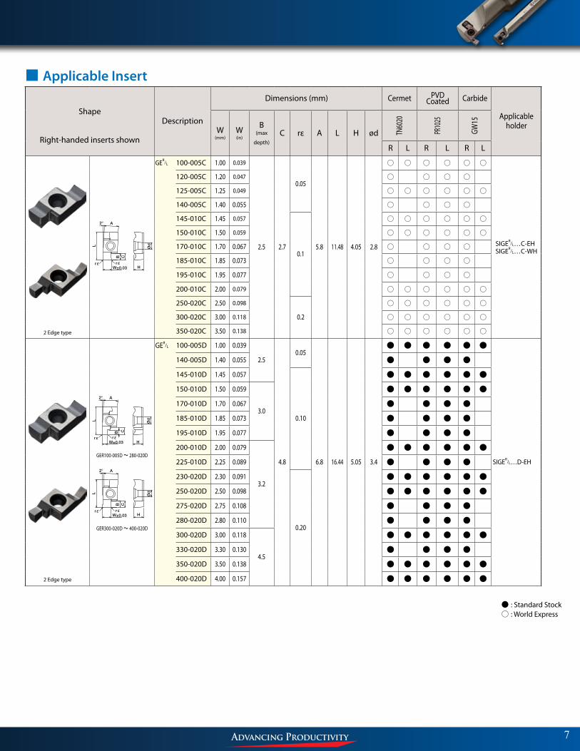
■ Applicable Insert
Shape
Right-handed inserts shown
Description
Dimensions (mm) Cermet PVD Coated Carbide
Applicable holderW
(mm)W(in)
B(max
depth)C rε A L H ød TN
6020
PR10
25
GW15
R L R L R L
2 Edge type
GER/L 100-005C 1.00 0.039
2.5 2.7
0.05
5.8 11.48 4.05 2.8
◦ ◦ ◦ ◦ ◦ ◦
SIGER/L…C-EHSIGER/L…C-WH
120-005C 1.20 0.047 ◦ ◦ ◦ ◦
125-005C 1.25 0.049 ◦ ◦ ◦ ◦ ◦ ◦
140-005C 1.40 0.055 ◦ ◦ ◦ ◦
145-010C 1.45 0.057
0.1
◦ ◦ ◦ ◦ ◦ ◦
150-010C 1.50 0.059 ◦ ◦ ◦ ◦ ◦ ◦
170-010C 1.70 0.067 ◦ ◦ ◦ ◦
185-010C 1.85 0.073 ◦ ◦ ◦ ◦
195-010C 1.95 0.077 ◦ ◦ ◦ ◦
200-010C 2.00 0.079 ◦ ◦ ◦ ◦ ◦ ◦
250-020C 2.50 0.098
0.2
◦ ◦ ◦ ◦ ◦ ◦
300-020C 3.00 0.118 ◦ ◦ ◦ ◦ ◦ ◦
350-020C 3.50 0.138 ◦ ◦ ◦ ◦ ◦ ◦
2 Edge type
L
A2°
B C
H
Ød
W±0.03rε rε
GER100-005D ~ 280-020D
L
A2°
B C
W±0.03 H
Ød
rε rε
GER300-020D ~ 400-020D
GER/L 100-005D 1.00 0.039
2.5
4.8
0.05
6.8 16.44 5.05 3.4
● ● ● ● ● ●
SIGER/L…D-EH
140-005D 1.40 0.055 ● ● ● ●
145-010D 1.45 0.057
0.10
● ● ● ● ● ●
150-010D 1.50 0.059
3.0
● ● ● ● ● ●
170-010D 1.70 0.067 ● ● ● ●
185-010D 1.85 0.073 ● ● ● ●
195-010D 1.95 0.077 ● ● ● ●
200-010D 2.00 0.079
3.2
● ● ● ● ● ●
225-010D 2.25 0.089 ● ● ● ●
230-020D 2.30 0.091
0.20
● ● ● ● ● ●
250-020D 2.50 0.098 ● ● ● ● ● ●
275-020D 2.75 0.108 ● ● ● ●
280-020D 2.80 0.110 ● ● ● ●
300-020D 3.00 0.118
4.5
● ● ● ● ● ●
330-020D 3.30 0.130 ● ● ● ●
350-020D 3.50 0.138 ● ● ● ● ● ●
400-020D 4.00 0.157 ● ● ● ● ● ●
L
A2°
B C
W±0.03 H
Ød
rε rε
7
◦ : Standard Stock◦ : World Express

8
■ Applicable Insert
Shape
Right-handed inserts shown
Description
Dimensions (mm) Cermet PVD Coated Carbide
Applicable holder
W(mm)
W(in)
B(max
depth)
C rε A L H ød TN60
20
PR10
25
GW15
R L R L R L
L
A2°
B C
H
Ød
W±0.03rε rε
GER100-005E ~ 430-020E
L
A2°
B C
W±0.03 H
Ød
rε rε
GER450-020E ~ 500-020E
GER/L 100-005E 1.00 0.039 2.5
6.8
0.05
9.54 21.66 5.55 4.4
● ● ● ● ● ●
SIGER/L…E-EH
150-010E 1.50 0.059
3.0
0.1
● ● ● ● ● ●
170-010E 1.70 0.067 ● ● ● ●
185-010E 1.85 0.073 ● ● ● ●
195-010E 1.95 0.077 ● ● ● ●
200-010E 2.00 0.079
3.2
● ● ● ● ● ●
225-010E 2.25 0.089 ● ● ● ●
230-020E 2.30 0.091
0.2
● ● ● ● ● ●
250-020E 2.50 0.098
4.5
● ● ● ● ● ●
275-020E 2.75 0.108 ● ● ● ●
280-020E 2.80 0.110 ● ● ● ●
300-020E 3.00 0.118 ● ● ● ● ● ●
330-020E 3.30 0.130 ● ● ● ●
350-020E 3.50 0.138
5.5
● ● ● ● ● ●
400-020E 4.00 0.157 ● ● ● ● ● ●
430-020E 4.30 0.169 ● ● ● ●
450-020E 4.50 0.177
6.5
● ● ● ● ● ●
460-020E 4.60 0.181 ● ● ● ●
500-020E 5.00 0.197 ● ● ● ● ● ●
Full-R W±0.03 H
L
2°
CB
A
Ød
rε
GER 200-100CR 2.00 0.079
2.5 2.7
1.0
5.8 11.48 4.05 2.8
● ●
SIGER…C-EH250-125CR 2.50 0.098 1.25 ● ●
300-150CR 3.00 0.118 1.5 ● ●
GER 200-100DR 2.00 0.079 3.24.8
1.0 6.8 16.44 5.05 3.4
● ●SIGER…D-EH
300-150DR 3.00 0.118 4.5 1.5 ● ●
●:Standard Stock
DescriptionApplicable Insert & Rake Angle (α) after Installment of Insert
Ground Chipbreaker α(°) 3-D Molded Chipbreaker α(°)
SIGER/L 0808A-EH GER/L100-005A~GER/L200-010A 5° - -
1010B-EHGER/L100-005B~GER/L300-020B 5° - -
1210B-EH
1412C-EH GER/L100-005C~GER/L350-020C GER200-100CR~GER300-150CR 8° GER150-010CM~GER350-020CM 10°
1612C-EH
2020D-EH GER/L100-005D~GER/L400-020D GER200-100DR~GER300-150DR 9° GER150-010DM~GER400-020DM 10°
2525E-EH
GER/L100-005E~GER/L500-020E 10° GER150-010EM~GER500-020EM 10°3232E-EH
4032E-EH
SIGER/L 0808A-WH GER/L100-005A~GER/L200-010A 5° - -
1010B-WHGER/L100-005B~GER/L300-020B 5° - -
1210B-WH
α indicates the rake angle at the center of the edge width, after installing insert8

■ Applicable Insert (Inch)
Shape
Right-handed inserts shown
Description
Dimensions (inch) PVD Coated
Applicable holder
WB
(max
depth)
C rε A L H ød PR10
25
R L
GER/L 031-002A 0.031 0.039
0.071
0.002
0.263 0.256 0.102 0.098
● ●
SIGER/L 05EH
041-002A 0.041 0.059 ● ●
047-002A 0.047 0.059 ● ●
058-002A 0.058 0.059 ● ●
062-004A 0.062 0.059
0.004
● ●
072-004A 0.072 0.059 ● ●
078-004A 0.078 0.059 ● ●
GER/L 031-002B 0.031 0.039
0.102
0.004
0.333 0.323 0.125 0.106
● ●
SIGER/L 06EH
041-002B 0.041 0.059 ● ●
047-002B 0.047 0.059 ● ●
058-002B 0.058 0.059 ● ●
062-004B 0.062 0.059 ● ●
072-004B 0.072 0.059 ● ●
078-004B 0.078 0.059 ● ●
088-004B 0.088 0.087 ● ●
094-004B 0.094 0.087 ●
097-004B 0.097 0.087 ● ●
105-008B 0.105 0.087
0.008
●
110-008B 0.110 0.087 ●
122-008B 0.122 0.087 ● ●
●:Standard Stock
Ød
H
L
W±0.001
A2°
CB
rε rε
9
DescriptionApplicable Insert & Rake Angle (α) after Installment of Insert
Ground Chipbreaker α(°) 3-D Molded Chipbreaker α(°)
SIGER/L 05-EH GER/L031-002A~GER/L078-004A5° - -
06-EH GER/L031-002B~GER/L122-008B
0809C-EH GER/L100-005C~GER/L350-020CGER200-100CR~GER300-150CR 8° GER150-010CM~GER350-020CM 10°
0810C-EH
1212D-EH GER/L100-005D~GER/L400-020DGER200-100DR~GER300-150DR 9° GER150-010DM~GER400-020DM 10°
1616E-EH
GER/L100-005E~GER/L500-020E 10° GER150-010EM~GER500-020EM 10°2020E-EH
2025E-EH
SIGER/L 0809C-WH GER/L100-005C~GER/L350-020CGER200-100CR~GER300-150CR 8° GER150-010CM~GER350-020CM 10°
0810C-WH
α indicates the rake angle at the center of the edge width, after installing insert
9
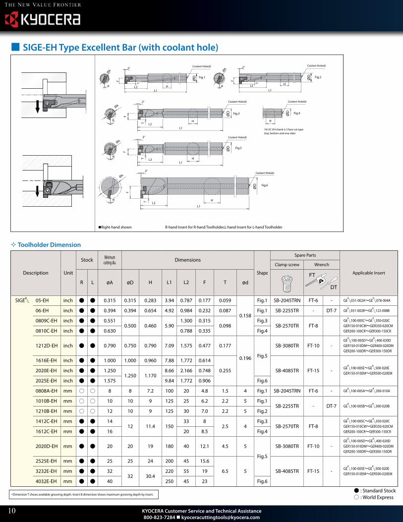
■ SIGE-EH Type Excellent Bar (with coolant hole)
F
T
L2L1
H
2°
F
T
L2L1
H
2°
ØA ØA
ØD ØD Fig.2Fig.1
Fig.3
Coolant Hole(d)
Coolant Hole(d)
Fig.4
Fig.5
Fig.6
1612C-EH shank is 3 face cut type(top, bottom and one side)
ØD
HL2
L1
2°
T
F
ØA
L1L2
F
2°
TØA
H
ØD
ØD
H
L1L2T
F
2°
ØA
Coolant Hole(d) Coolant Hole(d)
Coolant Hole(d) Coolant Hole(d)
H
ØD
Right-hand shown R-hand Insert for R-hand Toolholder,L-hand Insert for L-hand Toolholder
Toolholder Dimension
Description Unit
Stock Minimum cutting dia. Dimensions
Shape
Spare Parts
Applicable Insert
Clamp screw Wrench
R L øA øD H L1 L2 F T ødFT
DT
SIGER/L 05-EH inch ● ● 0.315 0.315 0.283 3.94 0.787 0.177 0.059
0.158
Fig.1 SB-2045TRN FT-6 - GER/L031-002A~GE
R/L078-004A
06-EH inch ● ● 0.394 0.394 0.654 4.92 0.984 0.232 0.087 Fig.1 SB-2255TR - DT-7 GER
/L031-002B~GER
/L122-008B
0809C-EH inch ● ● 0.5510.500 0.460 5.90
1.300 0.3150.098
Fig.3SB-2570TR FT-8
GER
/L100-005C~GER
/L350-020C GER150-010CM~GER350-020CM GER200-100CR~GER300-150CR0810C-EH inch ● ● 0.630 0.788 0.335 Fig.4
1212D-EH inch ● ● 0.790 0.750 0.790 7.09 1.575 0.477 0.177
0.196 Fig.5
SB-3080TR FT-10 -GE
R/L100-005D~GER
/L400-020D GER150-010DM~GER400-020DM GER200-100DR~GER300-150DR
1616E-EH inch ● ● 1.000 1.000 0.960 7.88 1.772 0.614
0.255 SB-4085TR FT-15 - GER
/L100-005E~GER
/L500-020E GER150-010EM~GER500-020EM2020E-EH inch ● ● 1.250
1.250 1.1708.66 2.166 0.748
2025E-EH inch ● ● 1.575 9.84 1.772 0.906 Fig.6
0808A-EH mm ◦ ◦ 8 8 7.2 100 20 4.8 1.5 4 Fig.1 SB-2045TRN FT-6 - GER
/L100-005A~GER
/L200-010A
1010B-EH mm ◦ ◦ 10 10 9 125 25 6.2 2.2 5 Fig.1SB-2255TR - DT-7 GE
R/L100-005B~GE
R/L300-020B
1210B-EH mm ◦ ◦ 12 10 9 125 30 7.0 2.2 5 Fig.2
1412C-EH mm ● ● 1412 11.4 150
33 82.5 4
Fig.3SB-2570TR FT-8
GER
/L100-005C~GER
/L350-020C GER150-010CM~GER350-020CM GER200-100CR~GER300-150CR1612C-EH mm ● ● 16 20 8.5 Fig.4
2020D-EH mm ● ● 20 20 19 180 40 12.1 4.5 5
Fig.5
SB-3080TR FT-10 -GE
R/L100-005D~GE
R/L400-020D
GER150-010DM~GER400-020DM GER200-100DR~GER300-150DR
2525E-EH mm ● ● 25 25 24 200 45 15.6
6.5 5 SB-4085TR FT-15 - GER
/L100-005E~GER
/L500-020E GER150-010EM~GER500-020EM3232E-EH mm ● ● 32
32 30.4220 55 19
4032E-EH mm ● ● 40 250 45 23 Fig.6
・ Dimension T shows available grooving depth. Insert B dimension shows maximum grooving depth by insert.
10
◦ : Standard Stock◦ : World Express
KYOCERA Customer Service and Technical Assistance 800-823-7284 [email protected]

■ SIGE-WH Type Carbide Anti-vibration Bar (with coolant hole)
L1
L2
F
T
2°
ØD
H
ØA
α
Coolant Hole(d)
Fig.1
Right-hand shown R-hand Insert for R-hand Toolholder,L-hand Insert for L-hand Toolholder
Toolholder Dimension
Description Unit
StockMinimum
cutting
dia.Dimensions
Shape
Spare Parts
Applicable InsertClamp screw Wrench
R L øA øD H L1 L2 F T ød
SIGER/L 0809C-WH inch ● ● 0.551
0.50 0.46
5.90 1.969 0.342 0.098
0.119 Fig.1
SB-2045TRN FT-6 - GER
/L100-005C~GE
R/L350-020C
GER150-010CM~GER350-020CM GER200-100CR~GER300-150CR
0810C-WH inch ● ● 0.630 7.09 (0.788 0.335 2.2 SB-2255TR - DT-7
11
FT
DT
◦ : Standard Stock◦ : World Express
4115
・Housing
・Vc=295 sfm
・ap=0.06"
・f=0.002 ipr
・Wet
・SIGER1412C-EH
GER250-010CM
(PR1025)ø0
.59”
1.18”
ø0.71”
PR1025
Competitor Coated H
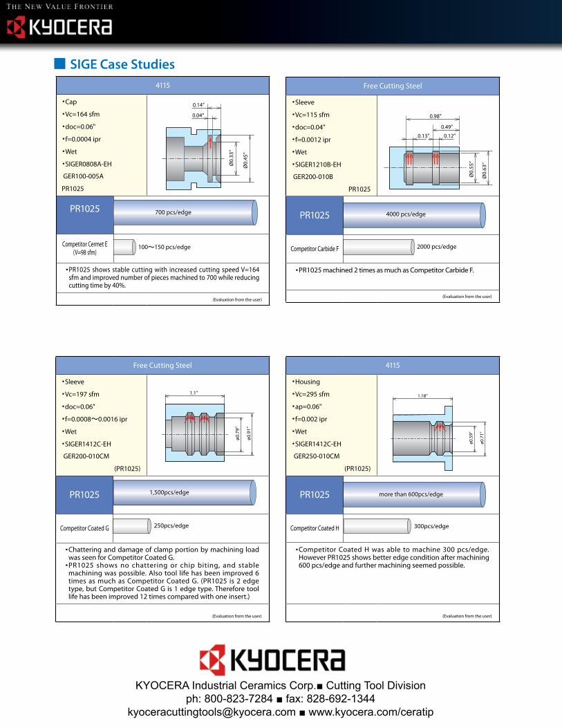
・ Competitor Coated H was able to machine 300 pcs/edge. However PR1025 shows better edge condition after machining 600 pcs/edge and further machining seemed possible.
(Evaluation from the user)
Free Cutting Steel
・Sleeve
・Vc=197 sfm
・doc=0.06"
・f=0.0008~0.0016 ipr
・Wet
・SIGER1412C-EH
GER200-010CM
(PR1025)
1.1”
ø0.79”
ø0.91”
PR1025
Competitor Coated G
・ Chattering and damage of clamp portion by machining load was seen for Competitor Coated G.
・ PR1025 shows no chattering or chip biting, and stable machining was possible. Also tool life has been improved 6 times as much as Competitor Coated G. (PR1025 is 2 edge type, but Competitor Coated G is 1 edge type. Therefore tool life has been improved 12 times compared with one insert.)
(Evaluation from the user)
4115
・Cap
・Vc=164 sfm
・doc=0.06"
・f=0.0004 ipr
・Wet
・SIGER0808A-EH
GER100-005A
PR1025
Ø0.33
”
0.14”
0.04”
Ø0.
45”
PR1025
Competitor Cermet E(V=98 sfm)
・ PR1025 shows stable cutting with increased cutting speed V=164 sfm and improved number of pieces machined to 700 while reducing cutting time by 40%.
(Evaluation from the user)
100~150 pcs/edge
Free Cutting Steel
・Sleeve
・Vc=115 sfm
・doc=0.04"
・f=0.0012 ipr
・Wet
・SIGER1210B-EH
GER200-010B
PR1025
0.49”
0.98”
0.12”0.13”
Ø0.55
”
Ø0.63
”
PR1025
Competitor Carbide F
・ PR1025 machined 2 times as much as Competitor Carbide F.
(Evaluation from the user)
2000 pcs/edge
4000 pcs/edge700 pcs/edge
1,500pcs/edge
250pcs/edge
more than 600pcs/edge
300pcs/edge
■ SIGE Case Studies
KYOCERA Industrial Ceramics Corp.■ Cutting Tool Divisionph: 800-823-7284 ■ fax: 828-692-1344
[email protected] ■ www.kyocera.com/ceratip


![INDEX []INDEX CUT-OFF CUT-OFF BLADES 10 TOOL BLOCKS 15 CUT-OFF AND GROOVING HOLDERS 16 FACE GROOVING 18 INTERNAL GROOVING 20 LAY DOWN 22 TOP NOTCH 23 …](https://img.dokumen.tips/doc/110x75/611b1599a3b8d808d74e4db3/index-index-cut-off-cut-off-blades-10-tool-blocks-15-cut-off-and-grooving-holders.jpg)