Embed Size (px)
Citation preview

Information
System
System Description D900/D1800
A30808-X3231-X45-1-7618

2 A30808-X3231-X45-1-7618
System Description D900/D1800 InformationSystem
Copyright (C) Siemens AG 1998
Issued by the Public Communication Network GroupHofmannstraße 51D-81359 München
Technical modifications possible.Technical specifications and features are binding only insofar asthey are specifically and expressly agreed upon in a written contract.
Important Notice on Product SafetyElevated voltages are inevitably present at specific points in this electrical equipment. Some of theparts can also have elevated operating temperatures.
Non-observance of these conditions and the safety instructions can result in personal injury or in prop-erty damage.
Therefore only trained and qualified personnel may install and maintain the system.
The system complies with the standard EN 60950. All equipment connected has to comply with theapplicable safety standards.
!

A30808-X3231-X45-1-7618 3
InformationSystem
System Description D900/D1800
This document consists of a total of 170 pages. All pages are issue 1.
Contents
1 Introduction . . . . . . . . . . . . . . . . . . . . . . . . . . . . . . . . . . . . . . . . . . . . . . . . . . 91.1 GSM900/GSM1800 PLMN for GSM900/GSM1800 Mobile Subscribers . . . 91.2 Combined Switching Center (CSC) . . . . . . . . . . . . . . . . . . . . . . . . . . . . . . 121.3 IN/CAMEL Functions in the PLMN and CSC . . . . . . . . . . . . . . . . . . . . . . . 131.4 Mobile Internet Access (MIA) . . . . . . . . . . . . . . . . . . . . . . . . . . . . . . . . . . . 13
2 Network Survey. . . . . . . . . . . . . . . . . . . . . . . . . . . . . . . . . . . . . . . . . . . . . . 152.1 GSM PLMN Service Areas . . . . . . . . . . . . . . . . . . . . . . . . . . . . . . . . . . . . . 152.2 D900/D1800 PLMN Subsystems . . . . . . . . . . . . . . . . . . . . . . . . . . . . . . . . 162.2.1 Switching Subsystem (SSS) . . . . . . . . . . . . . . . . . . . . . . . . . . . . . . . . . . . . 182.2.1.1 Mobile-Services Switching Center (MSC). . . . . . . . . . . . . . . . . . . . . . . . . . 182.2.1.2 Visitor Location Register (VLR). . . . . . . . . . . . . . . . . . . . . . . . . . . . . . . . . . 182.2.1.3 Home Location Register (HLR). . . . . . . . . . . . . . . . . . . . . . . . . . . . . . . . . . 182.2.1.4 Authentication Center (AC) . . . . . . . . . . . . . . . . . . . . . . . . . . . . . . . . . . . . . 192.2.1.5 Equipment Identification Register (EIR) . . . . . . . . . . . . . . . . . . . . . . . . . . . 192.2.1.6 Service Centers . . . . . . . . . . . . . . . . . . . . . . . . . . . . . . . . . . . . . . . . . . . . . 192.2.2 Base Station System (BSS) . . . . . . . . . . . . . . . . . . . . . . . . . . . . . . . . . . . . 192.2.2.1 Base Station Controller (BSC) . . . . . . . . . . . . . . . . . . . . . . . . . . . . . . . . . . 192.2.2.2 Base Transceiver Station (BTS) . . . . . . . . . . . . . . . . . . . . . . . . . . . . . . . . . 202.2.2.3 Transcoding and Rate Adaption Unit (TRAU). . . . . . . . . . . . . . . . . . . . . . . 202.2.3 O&M Subsystem (OMS) . . . . . . . . . . . . . . . . . . . . . . . . . . . . . . . . . . . . . . . 202.3 Connections between PLMN Network Elements . . . . . . . . . . . . . . . . . . . . 212.3.1 Traffic Connections . . . . . . . . . . . . . . . . . . . . . . . . . . . . . . . . . . . . . . . . . . . 222.3.2 Common Channel Signaling Connections . . . . . . . . . . . . . . . . . . . . . . . . . 232.3.3 O&M Connections. . . . . . . . . . . . . . . . . . . . . . . . . . . . . . . . . . . . . . . . . . . . 242.4 Combined Switching Center (CSC) . . . . . . . . . . . . . . . . . . . . . . . . . . . . . . 252.5 IN or CAMEL Functions in the PLMN and CSC . . . . . . . . . . . . . . . . . . . . . 272.6 Mobile Internet Access (MIA) Functions . . . . . . . . . . . . . . . . . . . . . . . . . . . 30
3 Telecommunication Services . . . . . . . . . . . . . . . . . . . . . . . . . . . . . . . . . . . 333.1 GSM Telecommunication Services. . . . . . . . . . . . . . . . . . . . . . . . . . . . . . . 333.1.1 Bearer Services . . . . . . . . . . . . . . . . . . . . . . . . . . . . . . . . . . . . . . . . . . . . . 333.1.2 Teleservices . . . . . . . . . . . . . . . . . . . . . . . . . . . . . . . . . . . . . . . . . . . . . . . . 343.1.3 Supplementary Services . . . . . . . . . . . . . . . . . . . . . . . . . . . . . . . . . . . . . . . 353.1.3.1 Number Identification Services . . . . . . . . . . . . . . . . . . . . . . . . . . . . . . . . . . 353.1.3.2 Call Offering Services . . . . . . . . . . . . . . . . . . . . . . . . . . . . . . . . . . . . . . . . . 363.1.3.3 Call Completion Services . . . . . . . . . . . . . . . . . . . . . . . . . . . . . . . . . . . . . . 373.1.3.4 Multi-Party Service . . . . . . . . . . . . . . . . . . . . . . . . . . . . . . . . . . . . . . . . . . . 373.1.3.5 Charging Services. . . . . . . . . . . . . . . . . . . . . . . . . . . . . . . . . . . . . . . . . . . . 373.1.3.6 Call Restriction Services . . . . . . . . . . . . . . . . . . . . . . . . . . . . . . . . . . . . . . . 383.1.3.7 Closed User Group (CUG) . . . . . . . . . . . . . . . . . . . . . . . . . . . . . . . . . . . . . 393.1.3.8 User-To-User Signaling Service 1 (UUS1) . . . . . . . . . . . . . . . . . . . . . . . . . 393.1.3.9 Non-GSM Supplementary Services . . . . . . . . . . . . . . . . . . . . . . . . . . . . . . 393.1.4 Subscriber Control of Supplementary Services . . . . . . . . . . . . . . . . . . . . . 403.2 Fixed Network Telecommunications Services at the CSC . . . . . . . . . . . . . 41

4 A30808-X3231-X45-1-7618
System Description D900/D1800 InformationSystem
3.3 IN or CAMEL Telecommunications Services in the M-SSP. . . . . . . . . . . . . 433.3.1 Categories of IN Services or CAMEL Services . . . . . . . . . . . . . . . . . . . . . . 433.3.2 GSM subscribers with Prepayment . . . . . . . . . . . . . . . . . . . . . . . . . . . . . . . 453.3.3 Charge Recording with the M-SSP . . . . . . . . . . . . . . . . . . . . . . . . . . . . . . . 45
4 Switching Subsystem (SSS) . . . . . . . . . . . . . . . . . . . . . . . . . . . . . . . . . . . . 464.1 System Architecture . . . . . . . . . . . . . . . . . . . . . . . . . . . . . . . . . . . . . . . . . . . 464.1.1 Network Elements . . . . . . . . . . . . . . . . . . . . . . . . . . . . . . . . . . . . . . . . . . . . 484.1.2 Combination of Network Elements. . . . . . . . . . . . . . . . . . . . . . . . . . . . . . . . 544.1.3 Interfaces . . . . . . . . . . . . . . . . . . . . . . . . . . . . . . . . . . . . . . . . . . . . . . . . . . . 564.2 Hardware . . . . . . . . . . . . . . . . . . . . . . . . . . . . . . . . . . . . . . . . . . . . . . . . . . . 604.2.1 Hardware Architecture . . . . . . . . . . . . . . . . . . . . . . . . . . . . . . . . . . . . . . . . . 604.2.1.1 Line Trunk Groups (LTG) . . . . . . . . . . . . . . . . . . . . . . . . . . . . . . . . . . . . . . . 624.2.1.2 Data Service Unit (DSU) . . . . . . . . . . . . . . . . . . . . . . . . . . . . . . . . . . . . . . . 644.2.1.3 Digital Line Unit B (DLUB) . . . . . . . . . . . . . . . . . . . . . . . . . . . . . . . . . . . . . . 654.2.1.4 Switching Network (SN(B)) . . . . . . . . . . . . . . . . . . . . . . . . . . . . . . . . . . . . . 664.2.1.5 Common Channel Network Control (CCNC) . . . . . . . . . . . . . . . . . . . . . . . . 674.2.1.6 Coordination Processor (CP113C/CR) . . . . . . . . . . . . . . . . . . . . . . . . . . . . 684.2.2 Mechanical Design. . . . . . . . . . . . . . . . . . . . . . . . . . . . . . . . . . . . . . . . . . . . 704.2.2.1 Rack Layout . . . . . . . . . . . . . . . . . . . . . . . . . . . . . . . . . . . . . . . . . . . . . . . . . 704.2.2.2 Layout Plan . . . . . . . . . . . . . . . . . . . . . . . . . . . . . . . . . . . . . . . . . . . . . . . . . 794.2.2.3 MiniSwitch
(Very Compact MSC/VLR Network Nodes, including Containers). . . . . . . . 804.3 Software . . . . . . . . . . . . . . . . . . . . . . . . . . . . . . . . . . . . . . . . . . . . . . . . . . . . 814.3.1 Software Architecture. . . . . . . . . . . . . . . . . . . . . . . . . . . . . . . . . . . . . . . . . . 814.3.1.1 Operating Systems. . . . . . . . . . . . . . . . . . . . . . . . . . . . . . . . . . . . . . . . . . . . 824.3.1.2 User Software . . . . . . . . . . . . . . . . . . . . . . . . . . . . . . . . . . . . . . . . . . . . . . . 844.3.2 Software Technology . . . . . . . . . . . . . . . . . . . . . . . . . . . . . . . . . . . . . . . . . . 864.3.2.1 Software Engineering Production Plan . . . . . . . . . . . . . . . . . . . . . . . . . . . . 864.3.2.2 Description and Implementation Languages . . . . . . . . . . . . . . . . . . . . . . . . 864.3.2.3 Support Software . . . . . . . . . . . . . . . . . . . . . . . . . . . . . . . . . . . . . . . . . . . . . 87
5 Base Station System (BSS) . . . . . . . . . . . . . . . . . . . . . . . . . . . . . . . . . . . . . 885.1 System Architecture . . . . . . . . . . . . . . . . . . . . . . . . . . . . . . . . . . . . . . . . . . . 885.1.1 Network Elements . . . . . . . . . . . . . . . . . . . . . . . . . . . . . . . . . . . . . . . . . . . . 885.1.2 Interfaces . . . . . . . . . . . . . . . . . . . . . . . . . . . . . . . . . . . . . . . . . . . . . . . . . . . 895.2 Hardware . . . . . . . . . . . . . . . . . . . . . . . . . . . . . . . . . . . . . . . . . . . . . . . . . . . 955.2.1 Hardware Architecture . . . . . . . . . . . . . . . . . . . . . . . . . . . . . . . . . . . . . . . . . 955.2.1.1 Base Transceiver Station Equipment (BTSE) BS-2x and BS-6x . . . . . . . . . 955.2.1.2 Base Transceiver Station Equipment (BTSE) BS-11 . . . . . . . . . . . . . . . . . . 995.2.1.3 Base Station Controller (BSC) . . . . . . . . . . . . . . . . . . . . . . . . . . . . . . . . . . 1025.2.1.4 Transcoding and Rate Adaption Unit (TRAU) . . . . . . . . . . . . . . . . . . . . . . 1045.2.2 Mechanical Design. . . . . . . . . . . . . . . . . . . . . . . . . . . . . . . . . . . . . . . . . . . 1055.2.2.1 Rack Layout . . . . . . . . . . . . . . . . . . . . . . . . . . . . . . . . . . . . . . . . . . . . . . . . 1055.2.2.2 Floor Layout . . . . . . . . . . . . . . . . . . . . . . . . . . . . . . . . . . . . . . . . . . . . . . . . 1105.3 Software . . . . . . . . . . . . . . . . . . . . . . . . . . . . . . . . . . . . . . . . . . . . . . . . . . . 1115.3.1 BS-2x and BS-6x BTSE Software . . . . . . . . . . . . . . . . . . . . . . . . . . . . . . . 1115.3.2 BS-11 BTSE Software . . . . . . . . . . . . . . . . . . . . . . . . . . . . . . . . . . . . . . . . 113

A30808-X3231-X45-1-7618 5
InformationSystem
System Description D900/D1800
5.3.3 BSC-Software . . . . . . . . . . . . . . . . . . . . . . . . . . . . . . . . . . . . . . . . . . . . . . 1145.3.4 TRAU-Software. . . . . . . . . . . . . . . . . . . . . . . . . . . . . . . . . . . . . . . . . . . . . 1165.3.5 Software Management . . . . . . . . . . . . . . . . . . . . . . . . . . . . . . . . . . . . . . . 118
6 O&M Subsystem (OMS) . . . . . . . . . . . . . . . . . . . . . . . . . . . . . . . . . . . . . . 1206.1 System Architecture . . . . . . . . . . . . . . . . . . . . . . . . . . . . . . . . . . . . . . . . . 1206.1.1 Network Components . . . . . . . . . . . . . . . . . . . . . . . . . . . . . . . . . . . . . . . . 1226.1.1.1 OMC for the SSS and BSS . . . . . . . . . . . . . . . . . . . . . . . . . . . . . . . . . . . . 1226.1.2 Interfaces of the OMS . . . . . . . . . . . . . . . . . . . . . . . . . . . . . . . . . . . . . . . . 1226.2 Hardware Architecture . . . . . . . . . . . . . . . . . . . . . . . . . . . . . . . . . . . . . . . 1236.2.1 Hardware of the OMC-S . . . . . . . . . . . . . . . . . . . . . . . . . . . . . . . . . . . . . . 1236.2.2 Hardware of the OMC-B . . . . . . . . . . . . . . . . . . . . . . . . . . . . . . . . . . . . . . 1246.3 Software Architecture . . . . . . . . . . . . . . . . . . . . . . . . . . . . . . . . . . . . . . . . 1256.3.1 Software Architecture of the OMC-S. . . . . . . . . . . . . . . . . . . . . . . . . . . . . 1256.3.2 Software Architecture of the OMC-B. . . . . . . . . . . . . . . . . . . . . . . . . . . . . 127
7 Functions . . . . . . . . . . . . . . . . . . . . . . . . . . . . . . . . . . . . . . . . . . . . . . . . . 1297.1 Basic Functions of Call Handling . . . . . . . . . . . . . . . . . . . . . . . . . . . . . . . 1297.2 Enhanced Functions of Call Routing, Charging and User Information . . . 1327.3 Mobile-Specific Functions of Call Handling. . . . . . . . . . . . . . . . . . . . . . . . 1357.4 Functions for Expanding PLMN Capacity . . . . . . . . . . . . . . . . . . . . . . . . . 1407.4.1 Standard Functions for Capacity Expansion. . . . . . . . . . . . . . . . . . . . . . . 1407.4.2 Supplementary Functions for a Capacity Expansion . . . . . . . . . . . . . . . . 1407.5 Fraud Prevention/Interception Functions . . . . . . . . . . . . . . . . . . . . . . . . . 1417.6 Special Operation and Maintenance Functions . . . . . . . . . . . . . . . . . . . . 1437.7 Signaling Functions. . . . . . . . . . . . . . . . . . . . . . . . . . . . . . . . . . . . . . . . . . 1457.8 Functional Sequence of Basic Call Types . . . . . . . . . . . . . . . . . . . . . . . . 146
8 Product Support . . . . . . . . . . . . . . . . . . . . . . . . . . . . . . . . . . . . . . . . . . . . 153
9 Quality Assurance. . . . . . . . . . . . . . . . . . . . . . . . . . . . . . . . . . . . . . . . . . . 1589.1 Hardware Quality Assurance . . . . . . . . . . . . . . . . . . . . . . . . . . . . . . . . . . 1599.2 Software Quality Assurance . . . . . . . . . . . . . . . . . . . . . . . . . . . . . . . . . . . 159
10 Abbreviations . . . . . . . . . . . . . . . . . . . . . . . . . . . . . . . . . . . . . . . . . . . . . . 161
11 Index . . . . . . . . . . . . . . . . . . . . . . . . . . . . . . . . . . . . . . . . . . . . . . . . . . . . . 169

6 A30808-X3231-X45-1-7618
System Description D900/D1800 InformationSystem
IllustrationsFig. 2.1 Subdivision of the D900/D1800 PLMN service areas . . . . . . . . . . . . . . . 16
Fig. 2.2 Structure of the D900/D1800 PLMN . . . . . . . . . . . . . . . . . . . . . . . . . . . . 17
Fig. 2.3 The D900/D1800 PLMN with its digital traffic connections . . . . . . . . . . . 22
Fig. 2.4 The D900 PLMN with its digital CCS7 connections . . . . . . . . . . . . . . . . 23
Fig. 2.5 The D900/D1800 PLMN with its digital O&M connections . . . . . . . . . . . 24
Fig. 2.6 CSC with GSM-RITL subscribers within a PSTN environment. . . . . . . . 26
Fig. 2.7 CSC with GSM-RITL subscribers within a PLMN environment . . . . . . . 26
Fig. 2.8 CSC with wired ISDN/analog subscribers within a PLMN environment . 26
Fig. 2.9 Underlying architecture of IN/CAMEL . . . . . . . . . . . . . . . . . . . . . . . . . . . 28
Fig. 2.10 Access to IN/CAMEL function in the PLMN with anintegrated IN/CAMEL network architecture. . . . . . . . . . . . . . . . . . . . . . . 29
Fig. 2.11 MIA Step 1 architecture for PLMN Internet access. . . . . . . . . . . . . . . . . 31
Fig. 4.1 Network structure of the SSS . . . . . . . . . . . . . . . . . . . . . . . . . . . . . . . . . 46
Fig. 4.2 Network elements of a PLMN-SSS with CSC. . . . . . . . . . . . . . . . . . . . . 47
Fig. 4.3 Access to IN/CAMEL functions via M-SSP in the PLMN . . . . . . . . . . . . 48
Fig. 4.4 Block diagram with a combined HLR/AC or HLR/AC/EIR orwith a stand-alone EIR network node . . . . . . . . . . . . . . . . . . . . . . . . . . . 54
Fig. 4.5 Block diagram with a combined MSC/VLR (including MiniSwitch) orMSC/VLR/HLR/AC node. . . . . . . . . . . . . . . . . . . . . . . . . . . . . . . . . . . . . 55
Fig. 4.6 Structure of a D900/D1800 network node in the SSS. . . . . . . . . . . . . . . 61
Fig. 4.7 Line/trunk group N (LTGN) . . . . . . . . . . . . . . . . . . . . . . . . . . . . . . . . . . . 63
Fig. 4.8 Line/trunk group G (LTGG) . . . . . . . . . . . . . . . . . . . . . . . . . . . . . . . . . . . 63
Fig. 4.9 Data service unit (DSU) . . . . . . . . . . . . . . . . . . . . . . . . . . . . . . . . . . . . . 64
Fig. 4.10 Digital line unit B (DLUB) . . . . . . . . . . . . . . . . . . . . . . . . . . . . . . . . . . . . 65
Fig. 4.11 Division of switching network (SN(B)) into time (T) andspace (S) stages (showing only one plane of the duplicated SN)and range of connection capacity . . . . . . . . . . . . . . . . . . . . . . . . . . . . . . 66
Fig. 4.12 Connection through the SN(B) (simplified) . . . . . . . . . . . . . . . . . . . . . . . 67
Fig. 4.13 Common channel network control (CCNC). . . . . . . . . . . . . . . . . . . . . . . 68
Fig. 4.14 Coordination processor (CP113C/CR) . . . . . . . . . . . . . . . . . . . . . . . . . . 69
Fig. 4.15 Standard racks of the coordination processor (CP113C)(Maximum capacity stage) . . . . . . . . . . . . . . . . . . . . . . . . . . . . . . . . . . . 72
Fig. 4.16 Racks for switching network B, message buffer B, centralclock generator A and line/trunk group N(R:SNB/MB/LTGN) . . . . . . . . . 73
Fig. 4.17 Rack for service equipment: analog modems for remoteBCT connection, digital announcement system (DAS) andsystem panel control (SYPC) . . . . . . . . . . . . . . . . . . . . . . . . . . . . . . . . . 74
Fig. 4.18 Racks for line/trunk group N (LTGN), as well as partiallyequiped with LTGN and LTGG . . . . . . . . . . . . . . . . . . . . . . . . . . . . . . . . 75
Fig. 4.19 Racks for common channel network control (CCNC) . . . . . . . . . . . . . . . 76
Fig. 4.20 Rack for DSU . . . . . . . . . . . . . . . . . . . . . . . . . . . . . . . . . . . . . . . . . . . . . 77
Fig. 4.21 Rack for DLUB (R:DLUB) . . . . . . . . . . . . . . . . . . . . . . . . . . . . . . . . . . . . 78
Fig. 4.22 Example layout draft for an MSC/VLR network node . . . . . . . . . . . . . . . 79
Fig. 4.23 Rack layout for a MiniSwitch (example) . . . . . . . . . . . . . . . . . . . . . . . . . 80

A30808-X3231-X45-1-7618 7
InformationSystem
System Description D900/D1800
Fig. 4.24 Software shells for a processor . . . . . . . . . . . . . . . . . . . . . . . . . . . . . . . 81
Fig. 5.1 Structure of the D900/D1800 BSS. . . . . . . . . . . . . . . . . . . . . . . . . . . . . 88
Fig. 5.2 Radio channel assignment for the D900 BSS(GSM900 primary band) . . . . . . . . . . . . . . . . . . . . . . . . . . . . . . . . . . . . 90
Fig. 5.3 Radio channel assignment for the D900 BSS(GSM900 extended band G1) . . . . . . . . . . . . . . . . . . . . . . . . . . . . . . . . 90
Fig. 5.4 Radio channel assignment for the D1800 BSS . . . . . . . . . . . . . . . . . . . 91
Fig. 5.5 Time division multiplex access (TDMA) frame of theGSM radio interface of the BSS. . . . . . . . . . . . . . . . . . . . . . . . . . . . . . . 92
Fig. 5.6 Time slot with a normal burst . . . . . . . . . . . . . . . . . . . . . . . . . . . . . . . . . 93
Fig. 5.7 Frame structure of the radio interface of the BSS . . . . . . . . . . . . . . . . . 94
Fig. 5.8 Functional structure of the BS-2x and BS-6x BTSE(with separate TX and RX paths). . . . . . . . . . . . . . . . . . . . . . . . . . . . . . 96
Fig. 5.9 Functional structure of the BS-2x and BS-6x BTSE(with duplex combiner (DUCOM)) . . . . . . . . . . . . . . . . . . . . . . . . . . . . . 96
Fig. 5.10 Functional structure of the BS-2x and BS-6x BTSE(with Duplexer and LNA module (DULAMO)) . . . . . . . . . . . . . . . . . . . . 97
Fig. 5.11 Functional structure of the BS-11 BTSE (with integrated antennas) . . . 99
Fig. 5.12 Functional structure of the BS-11 BTSE (with external antennas). . . . 100
Fig. 5.13 Functional structure of the BSC. . . . . . . . . . . . . . . . . . . . . . . . . . . . . . 102
Fig. 5.14 Functional structure of the TRAU. . . . . . . . . . . . . . . . . . . . . . . . . . . . . 104
Fig. 5.15 BTSE products (“standard” type BTS and micro BTS equipment). . . . 105
Fig. 5.16 BTSE rack/cabinet configurations (type BS-60 for indoorinstallation and type BS-11 with integrated antenna). . . . . . . . . . . . . . 106
Fig. 5.17 BSC rack configuration . . . . . . . . . . . . . . . . . . . . . . . . . . . . . . . . . . . . 108
Fig. 5.18 TRAU rack configuration . . . . . . . . . . . . . . . . . . . . . . . . . . . . . . . . . . . 109
Fig. 5.19 BS-2x and BS-6x BTSE software architecture. . . . . . . . . . . . . . . . . . . 111
Fig. 5.20 BS-11 BTSE software architecture . . . . . . . . . . . . . . . . . . . . . . . . . . . 113
Fig. 5.21 BSC software architecture . . . . . . . . . . . . . . . . . . . . . . . . . . . . . . . . . . 114
Fig. 5.22 TRAU software architecture. . . . . . . . . . . . . . . . . . . . . . . . . . . . . . . . . 116
Fig. 6.1 OMS network architecture . . . . . . . . . . . . . . . . . . . . . . . . . . . . . . . . . . 120
Fig. 6.2 National OMC for OMC-B . . . . . . . . . . . . . . . . . . . . . . . . . . . . . . . . . . 121
Fig. 6.3 OMC for the SSS and BSS . . . . . . . . . . . . . . . . . . . . . . . . . . . . . . . . . 122
Fig. 6.4 Components of OMS-S software . . . . . . . . . . . . . . . . . . . . . . . . . . . . . 125
Fig. 7.1 Call procedure of an MOC to a fixed network subscriber . . . . . . . . . . 146
Fig. 7.2 Call procedure of an MTC (with call origin in the fixed network) . . . . . 147
Fig. 7.3 Call procedure of an MMC. . . . . . . . . . . . . . . . . . . . . . . . . . . . . . . . . . 148
Fig. 7.4 Call procedure of a fixed ISDN subscriber to theGSM subscriber at the shared CSC. . . . . . . . . . . . . . . . . . . . . . . . . . . 149
Fig. 7.5 MOC call procedure to IN/CAMEL applications, whenGSM subscriber is roaming inside the HPLMN . . . . . . . . . . . . . . . . . . 151
Fig. 7.6 MOC call procedure to IN/CAMEL applications, whenGSM subscriber is roaming outside the HPLMN . . . . . . . . . . . . . . . . . 152
Fig. 8.1 Top-down structure of the operating documentation . . . . . . . . . . . . . . 156

8 A30808-X3231-X45-1-7618
System Description D900/D1800 InformationSystem
TablesTab. 2.1 Overview of all kinds of subscribers at the CSC
(with classifying features) . . . . . . . . . . . . . . . . . . . . . . . . . . . . . . . . . . . . 25
Tab. 3.1 Basic telecommunications services for wired ISDN subscribersat the CSC . . . . . . . . . . . . . . . . . . . . . . . . . . . . . . . . . . . . . . . . . . . . . . . 41
Tab. 3.2 Telecommunications services for wired analog subscribersat the CSC . . . . . . . . . . . . . . . . . . . . . . . . . . . . . . . . . . . . . . . . . . . . . . . 42
Tab. 3.3 Categories of IN services or CAMEL services in the CSC-SSPand M-SSP . . . . . . . . . . . . . . . . . . . . . . . . . . . . . . . . . . . . . . . . . . . . . . . 43

A30808-X3231-X45-1-7618 9
InformationSystem
System Description D900/D1800
1 IntroductionA growing number of customers of the telecommunication administrations and operatorswould like to have modern communication facilities at their disposal wherever and when-ever they need them. In order to meet this demand on an international scale, the Euro-pean Telecommunication Standards Institute (ETSI) has specified the GSM (GlobalSystem for Mobile Communication).
1.1 GSM900/GSM1800 PLMN for GSM900/GSM1800 MobileSubscribersGSM900/GSM1800 defines a standard for a public land mobile network (PLMN). TheGSM900 primary band will be operated in the 900 MHz frequency range (890-915 MHzuplink or 935-960 MHz downlink) and the GSM900 extension band G1 in the frequencyrange (880-915 MHz uplink or 925-960 MHz downlink). The GSM1800 will be operatedin the 1800 MHz frequency range (1710-1785 MHz uplink or 1805-1880 MHz downlink).
The GSM900/GSM1800 standard is the first international standard which allows themobile subscriber full access to the networks of the different PLMN operators in all thecountries that have chosen the GSM900/GSM1800 as standard. TheGSM900/GSM1800 standard represents a second generation mobile communicationsystem.
Phase 1 of this GSM900/GSM1800 standard was finalized by ETSI in 1990. The secondstage (Phase 2 ) was approved in 1995 and the appropriate features will be introducedinto the networks from 1996 onwards. An extension of the second step (Phase 2+ )meets the needs which have also arisen from practical operation since the introductionof the GSM900/GSM1800 standard.Phase 1 comprised basic PLMN functions plus telecommunications services and full-rate channel calls. Phase 2 contains supplementary telecommunications services (suchas conference calls, etc.) and support of half-rate channel calls. Phase 2+ involves newservices and technical precautions for new applications based on theGSM900/GSM1800 standard. Examples of such include: Call completion to busysubscriber (CCBS), call transfer (CT), handover at extremely high speeds, access toDECT networks, to satellite networks and to IN/CAMEL services, etc.
Siemens' digital cellular mobile communication system D900/D1800 implements theGSM900/GSM1800 standard to Phase 1 and Phase 2/2+ for a PLMN and uses the verylatest technologies in order to meet all the requirements of this international communi-cation system. D900/D1800 is the first system to exploit the potential for innovationmade possible by digital voice transmission for cellular telephones. In addition to theenhanced connection quality, a number of other improvements has been made, such asefficient utilization of the frequency spectrum.
The advantages of D900/D1800:
Spectrum efficiency
The radio-frequency channel spacing, i.e. the width of the frequency band allocated toone radio-frequency channel should be wide enough to ensure good voice transmissionquality, yet simultaneously narrow enough to permit good spectrum efficiency. Time-division multiple access operation, i.e. utilizing a radio-frequency channel by more thanone traffic or control channel, is an excellent means of expanding spectrum efficiency.

10 A30808-X3231-X45-1-7618
System Description D900/D1800 InformationSystem
Efficient utilization of the radio-frequency channels is achieved by splitting a carrier intotime slots, which are used as the physical channel for various types of logical channels.
Cost-effectiveness
In analog systems a separate transmitter and receiver are needed for each connection.In contrast, a D900/D1800 base station system with one transmitter and one receivercan carry up to eight traffic channels simultaneously. This is due to the application of thetime division multiple access (TDMA) principle.
As a consequence, equipment costs, space requirements and energy consumption areall considerably reduced. In addition, a series of further technical features add to thehigh cost-effectiveness of the D900/D1800, such as digital voice transmission, highestspectrum efficiency for the maximum number of subscribers, maximum use of the trunksbetween mobile-services switching center (MSC) and base station system (BSS), andextensive central and local operation possibilities.
Improved transmission quality for voice and data
The transmission quality of the D900/D1800 is better than that of any other cellularsystem. This is due to the method of transmission developed and optimized specially forD900/D1800.
For voice transmission, the analog electrical voice signal generated by the microphoneis converted in a specific voice coding process in the case of full-rate or enhanced full-rate channels into a 13 kbit/s bit stream (supplemented with 3 kbit/s associatedsignaling to form a 16 kbit/s traffic signal) and then transmitted digitally over radio at arate of 22.8 kbit/s.
This increased radio transmission rate results from additional protection procedures thatincrease immunity to radio-frequency interference. The connection quality is thus to agreat extent independent of the radio link quality.
Furthermore the D900/D1800 supports a half-rate channel operation or a dual-rate/triple-mode operation with parallel full-rate/enhanced full-rate and half-rate chan-nels.
For half-rate channels, half the data rate is correspondingly obtained for voice transmis-sion, i.e. a 6.5 kbit/s bit-stream after voice conversion, or 11.4 kbit/s as the radio trans-mission rate. The sub-multiplex traffic signal remains unchanged, as for the16-kbit/s full-rate channels.
For data transmission (asynchronous, circuit-oriented or packet-oriented) the digitaldata signal is fed via a special interworking function (IWF). The IWF performs functionssuch as rate matching, modem and codec, to permit matching to the network conditionsof the communication partner in the stationary network.
Protection against interception by means of ciphering
Because of the use of digital voice transmission it is possible for the first time with theD900/D1800 to cipher all messages in such a way that even experts are not capable ofintercepting the calls. This is done by an ciphering process similar to those which, up tonow, have been used exclusively for military purposes.
Protection against unauthorized network access by authentication
A special network access check ensures that only authorized mobile users obtainaccess to the GSM900/GSM1800 network. This is achieved by comparing the authenti-cation parameters of the mobile user side and of the network side in the D900/D1800.

A30808-X3231-X45-1-7618 11
InformationSystem
System Description D900/D1800
New GSM900/GSM1800 basic telecommunication services
The system D900/D1800 was optimized principally with its most common application,GSM900/GSM1800 teleservice telephony, in mind. But access to non-voice serviceswas also taken into consideration at the beginning of the design stage, in contrast toconventional systems. The GSM900/GSM1800 mobile subscriber has at his disposal fora connection many bearer services and teleservices, such as data transmissionservices via PSTN/ISDN (asynchronous, circuit-switched) or via PSDN (packet-oriented) as well as fax and short message service, including short message cell broad-cast.
New GSM900/GSM1800 supplementary services
The D900/D1800 offers the mobile subscriber numerous GSM900/GSM1800 supple-mentary services, all of which are usable on the teleservice telephony and partly also onthe other basic telecommunication services. Examples of supplementary services inaccordance with the GSM900/GSM1800 standard are call forwarding, call restrictionservices, advice of charge, calling line identification presentation, closed user groups,call transfer or call completion to busy subscriber. In addition to the GSM900/GSM1800supplementary services it is also possible to implement on a project-specific basis alsonon-GSM900/GSM1800 supplementary services in a national PLMN.
High system availability and cost-effectiveness in operation
D900/D1800 has a very high system availability due to the duplication of all importantfunctional units and to additional safeguarding functions in hardware and software. Inaddition, decentralized supervision in the functional units reduces repair times bylocating faults precisely.
To a large extent, operation and maintenance are carried out from central operation andmaintenance centers (O&M centers) by remote control. Of course, on-site operation andmaintenance is also possible via local or mobile O&M terminals. D900/D1800 can inmost areas be adapted to the operating company's own operation and maintenanceconcepts.
The mobile station, your constant companion
The mobile stations of cellular systems are becoming smaller and smaller. On the onehand this is a result of technological progress, especially in the field of large-scale inte-gration, and on the other hand the result of the subscriber's desire to be able to tele-phone everywhere using a handy device not larger than a pocket calculator.
D900/D1800 fulfils these requirements. Smaller handsets are possible for the simplereason that the transmit/receive control still required by analog systems is not necessaryhere. A further great improvement has been made with the specific energy-saving tech-nology of the D900/D1800 system.
In order to be always ready to receive a call, the mobile stations must scan the signalingtransmitted by the base station systems at all times, also without connection operation.With the D900/D1800, calls to the mobile stations are transmitted at certain timescontrolled by clock pulses. This means that the mobile stations only need to switch ontheir receivers at these times, thus requiring only a fraction of the battery power. Thehandsets can therefore manage with smaller and lighter batteries. Furthermore, theycan operate for longer without a change of battery or recharging.
Use of frequency hopping and antenna diversity provides greater range at lower trans-mission power and improves transmission quality.

12 A30808-X3231-X45-1-7618
System Description D900/D1800 InformationSystem
Total mobility with the ID chip card
All GSM900/GSM1800 mobile subscribers are issued with an ID chip card (SIM,subscriber identity module) for their mobile stations which offers absolute protectionagainst misuse. With this ID chip card, which has the same format as a credit card, theGSM900/GSM1800 mobile subscribers can use mobile stations (or the portable phone)e.g. in a rented car as if it were their own: calls are directed to the mobile station in whichthe GSM900/GSM1800 mobile subscribers have checked in their ID chip card. The callcharges are billed to the card owner. Even the personal telephone number index forabbreviated dialing can be stored on the ID chip card and used at other mobile stations.
Product maintenance
Teams of highly qualified developers, equipped with the latest development tools,continue to provide product maintenance. Research groups ensure that innovationpossibilities of advantage to technology and application are recognized at an early stageand implemented at the right time. Numerous proven methods of quality assuranceguarantee high quality.
Product support for the customer
For the lifetime of the system, D900/D1800 is accompanied by extensive productsupport. Among others, the following features are offered: documentation, training,network planning, installation planning, assembly, a range of spare parts, repairservices, the implementation of new features, handling of turnkey projects. If required,Siemens can therefore relieve the operating company of a large number of tasks.
1.2 Combined Switching Center (CSC)In addition to implementing a GSM900/GSM1800-PLMN for classicalGSM900/GSM1800 mobile subscribers the D900/D1800 allows for provision of conven-tional non-GSM900/GSM1800 mobile subscribers within a PLMN. Access and adminis-tration is handled by what is known as a combined switching center (CSC), which isintegrated into the PLMN instead of a mobile switching center (MSC) for example.
In a CSC following types of subscribers can be administered and connected:• GSM900/GSM1800 subscribers following the GSM900/GSM1800 standard
– GSM900/GSM1800 mobile subscribers– GSM900/GSM1800-RITL subscribers (radio-in-the-loop subscribers,
which are supported via the GSM900/GSM1800 radio interface too)• fixed network subscribers
– ISDN/analog subscribers,either as main station or basic access or via private automatic branch exchanges(PABX),
Both GSM900/GSM1800-RITL subscribers and ISDN/analog subscribers at the CSCare administered with respect to their directory numbers as subscribers of the localnetwork area belonging to the CSC - similar to the subscribers of a stand-alone localexchange (LE).The fixed network subscribers of the CSC (ISDN/analog subscribers) are connected bywireline to the CSC.

A30808-X3231-X45-1-7618 13
InformationSystem
System Description D900/D1800
1.3 IN/CAMEL Functions in the PLMN and CSCAll GSM mobile subscribers of a PLMN can be provided with Intelligent Network (IN)services or Customized Application for Mobile network Enhanced Logic (CAMEL)services.
The fixed network subscribers and GSM-RITL subscriber of a CSC can be provided withIntelligent Network (IN) services.
1.4 Mobile Internet Access (MIA)Incredible growth of the Internet and a concurrent growth in demand for cellular telecom-munications services has led to increased market demand for mobile access to theInternet. Current technical limitations require that mobile Internet access (MIA) berouted over PSTN/ISDN, resulting in lengthy and costly communications access require-ments for mobile access to the Internet.
PLMN operators should be able to offer their mobile customers direct mobile internetaccess to reduce the required access time to data services and limit their reliance onPSTN, thereby enhancing the usage of mobile data communication to the Internet.While increasing airtime usage operators can tap into a new source of revenue by them-selves becoming mobile Internet service providers (ISP). The PLMN operator canthereby leverage the huge resources of Internet protocol (IP) based applications, bydifferentiating himself from other competitors.
This section describes the Siemens mobile Internet strategy. Siemens plans to offer anevolutionary approach to mobile Internet access (MIA):
1. Step 1: Stand alone solution (realized in the current software version)The PLMN operator will be offered an Internet protocol (IP) based value addedservice (VAS) platform, necessary to become an internet service provider. The plat-form is based on Siemens tested third party (OEM) products, but in accordance withthe Siemens internet strategy. Thus the costly routing through the PSTN to accessthe Internet is obsoleted for the PLMN operator as he is now able to directly accessthe Internet.
2. Step 2: Integration and voice over Internet protocol (VoIP)Functionality’s of the VAS platform will be integrated by Siemens into the PLMN ,additionally in accordance with the Siemens Internet strategy new services like VoIPwill be offered.
iIn the following sections of the System Description, the GSM900/GSM1800 notation isreduced to the abbreviated GSM notation, whereby all the statements about GSM900also apply in GSM1800 PLMN. This gives rise to the following equivalents, for example:
GSM900/GSM1800 subscriber = GSM subscriberGSM900/GSM1800 mobile subscriber = GSM mobile subscriberGSM900/GSM1800-RITL subscriber = GSM-RITL subscriberGSM900/GSM1800 radio interface = GSM radio interfaceGSM900/GSM1800 mobile station = GSM mobile stationGSM900/GSM1800 standard = GSM standardGSM900/GSM1800 PLMN = GSM PLMN

14 A30808-X3231-X45-1-7618
System Description D900/D1800 InformationSystem
3. Step 3: Introduction of high speed circuit switched data (HSCSD)service andGeneral packet radio (GPRS) serviceNew data services will be introduced by Siemens to address higher bandwidth,connectionless communication, flexibility of radio resource usage and circuit andpacket switched transmission topics. These services will leverage the advantagesof the solution realized in the step 1 and 2. However they can be introduced withoutthe two previous mobile Internet access steps. HSCSD will achieve data rates of28.8 kbit/s and GPRS will achieve data rates of 100 kbit/s.
In the future (approximately in the year 2002) the MIA Step 3 flows into the 3rd mobilegeneration standard Universal mobile telecommunications system (UMTS). WithinUMTS the data rates generally will achieve 2 Mbit/s for stationary and 384 kbit/s formoving applications.

A30808-X3231-X45-1-7618 15
InformationSystem
System Description D900/D1800
2 Network SurveyAs shown in the previous Section 1, the D900/D1800 system concept offers the compo-nents:• GSM PLMN (cellular mobile radio system), for "connecting" GSM mobile
subscribers• CSC (combined switching center), for the connection of GSM subscribers (GSM
mobile subscribers and GSM-RITL subscribers) and fixed network subscribers(wirelined ISDN/analog subscribers)
• IN/CAMEL network functions in the GSM PLMN and CSC(for GSM subscribers and for fixed network subscribers in the GSM PLMN or in theCSC)
• Mobile Internet access (MIA) functions
Sections 2.1 through 2.3 deal exclusively with the GSM PLMN, whereas Section 2.4explains the CSC and Section 2.5 explains the IN/CAMEL functionality and Section 2.6explains the MIA functionality.
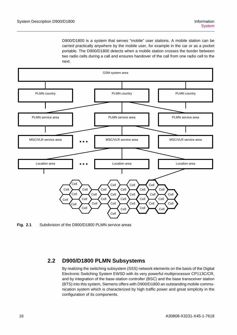
2.1 GSM PLMN Service AreasD900/D1800 is a cellular radio system. The whole public land mobile network (PLMN)area is covered by a great number of radio cells, as is usual with mobile radio systems(Fig. 2.1).
A cell (radio cell) is the smallest service area where particular radio channel equipmentis used for a connection and the telecommunication services are supplied by a basetransceiver station (BTS). Within the radio cell service area a defined quality of receptionis provided.
One or more radio cells form a location area . A location area is a service area in whicha GSM mobile subscriber may move freely without updating a location (or visitor)register. The size of a location area is determined by the operator to meet the demandsimposed by traffic density and flow, population density and GSM mobile subscribermobility.
One or more location areas form a service area of a mobile services switchingcenter/visitor location register (MSC/VLR area). The MSC/VLR service area is that partof the PLMN supported by the MSC/VLR and can embrace any area from an urbandistrict to an entire country.
One or more MSC/VLR service areas form the PLMN area . This is the geographicalarea inside which an operator provides telecommunications services. Several areasmay geographically overlap.
A PLMN country may consist of one or more PLMN areas. A GSM system areacomprises one or more PLMN countries.
A 'service area' is defined as an area in which a GSM mobile subscriber can be reachedby another subscriber without the subscriber's knowledge of the actual location of theGSM mobile subscriber within the area. The location registration system associated witheach service area must thus contain a list of all GSM mobile subscribers located withinthat service area.
16 A30808-X3231-X45-1-7618
System Description D900/D1800 InformationSystem
D900/D1800 is a system that serves ”mobile” user stations. A mobile station can becarried practically anywhere by the mobile user, for example in the car or as a pocketportable. The D900/D1800 detects when a mobile station crosses the border betweentwo radio cells during a call and ensures handover of the call from one radio cell to thenext.
Fig. 2.1 Subdivision of the D900/D1800 PLMN service areas
2.2 D900/D1800 PLMN SubsystemsBy realizing the switching subsystem (SSS) network elements on the basis of the DigitalElectronic Switching System EWSD with its very powerful multiprocessor CP113C/CR,and by integration of the base-station controller (BSC) and the base transceiver station(BTS) into this system, Siemens offers with D900/D1800 an outstanding mobile commu-nication system which is characterized by high traffic power and great simplicity in theconfiguration of its components.
Cell
Cell
Cell
Cell
Cell
Cell
Cell
Cell
Cell
Cell
Cell
Cell
Cell
Cell
Cell
Cell
Cell
Cell
Cell
Cell
Cell
Cell
Cell
Cell
Cell
Cell
Cell
Cell
Cell
CellCell
Cell
Cell
PLMN country
GSM system area
PLMN countryPLMN country
PLMN service area PLMN service area PLMN service area
MSC/VLR service area MSC/VLR service area MSC/VLR service area
Location area Location area Location area

A30808-X3231-X45-1-7618 17
InformationSystem
System Description D900/D1800
The mobile communication system D900/D1800 realizes a GSM PLMN and consists ofthree subsystems (Fig. 2.2):• the switching subsystem (SSS)
which offers all switching functions, also fixed-network-specific switching functions,that are necessary either for independent operation of the D900/D1800 network orfor combined operation of the D900/D1800 network and a fixed network (e.g.PSTN/ISDN) or another mobile radio network
• the radio subsystem (RSS) divided into:– the base-station system (BSS )
which offers all functions necessary to provide both the radio coverage of theservice area and an extensive distributed intelligence
– the mobile station (MS) , which is not part of the D900/D1800;offers all GSM mobile subscribers operating functions
• the operation and maintenance subsystem (OMS)which offers all functions necessary for operation of the D900/D1800 network andfor the acquisition of information about the performance of the D900/D1800 system.
Fig. 2.2 Structure of the D900/D1800 PLMN
OMC-SOMC-B
Radio cell
Radio cell
MS
MS
othernetworks
Radio subsystem (RSS) Switching subsystem (SSS)
O&M subsystem (OMS)
BTS
BTS
BTS
BTS
BSC/TRAU
BSC/TRAU
MSC/VLR
HLR/AC EIR
OMP-S
OMT-S OMT-S
Base stations system (BSS)
other MSCs
Service centers(SMS centers,
VMS)
Operationssystem (OS)
OMP-B
OMT-B OMT-B
uplink

18 A30808-X3231-X45-1-7618
System Description D900/D1800 InformationSystem
2.2.1 Switching Subsystem (SSS)The switching subsystem (SSS) consists of the following network elements:– mobile-services switching center (MSCs)– visitor location register (VLR)– authentication center (AC)– home location register (HLR)– equipment identification register (EIR).
The SSS supports the full-rate/enhanced full-rate channel operation for speech and dataservices and the half-rate channel operation for speech services.
2.2.1.1 Mobile-Services Switching Center (MSC)The MSC establishes mobile calls– between the D900/D1800 mobile radio network and a fixed network (e.g.
PSTN/ISDN, PSDN or Internet)– between the D900/D1800 mobile radio network and another mobile radio network– within the D900/D1800 mobile radio network between GSM mobile subscribers
In the case of mobile to mobile calls within the D900/D1800 network a connection fromone MSC to another MSC or within one MSC is established.
Interworking functions in the MSC make the D900/D1800 compatible with othernetworks. The MSC can be physically located either in an exchange site of the fixednetwork or in any other convenient place within or even outside the service area.
2.2.1.2 Visitor Location Register (VLR)The VLR is a database containing information about all GSM mobile subscriberscurrently active in its area of responsibility. In D900/D1800 the VLR is collocated withthe MSC at a physical network node, for which the abbreviation MSC/VLR is used.When a subscriber checks in with the VLR, this information is forwarded to the homelocation register (HLR).
In response the VLR receives from the HLR the corresponding GSM mobile subscriberdata. For incoming calls for the GSM mobile subscriber the VLR delivers the mobilestation roaming number (MSRN) at the request of the HLR. This number serves toestablish the traffic channel connection to the visited MSC.
2.2.1.3 Home Location Register (HLR)The HLR is the main database for GSM mobile subscriber data. It contains the relevantdata of its registered GSM mobile subscribers. Included in the relevant data is informa-tion about the VLR service area in which the GSM mobile subscriber is temporarilyroaming. This information is needed for directing calls to the GSM mobile subscriber. InD900/D1800 the HLR is collocated with the AC in a physical network node, for which theabbreviation HLR/AC is used.

A30808-X3231-X45-1-7618 19
InformationSystem
System Description D900/D1800
2.2.1.4 Authentication Center (AC)The AC contains several security boxes with keys and algorithms required for theproduction of authentication parameters. In the AC several sets of authentication param-eters, called 'triples', are generated for each GSM mobile subscriber generally beforethe GSM mobile subscriber's access to the mobile radio network. The triples are usedby the VLR for authentication checks, i.e. to prove whether a GSM mobile subscriber isauthorized to enter the network and set up a call. After the check the used triple is abol-ished and after reaching a certain threshold in the VLR, the VLR will request a set of newtriples from the AC via the HLR.
2.2.1.5 Equipment Identification Register (EIR)The EIR is another database containing information about the device types and identitynumbers of all mobile stations (MS) admitted in its area of responsibility. The EIR canbe organized in relation to network areas, e.g. with reference to one or more MSCs. Inaddition there may be a supra-regional master EIR outside of the PLMN. If requested bythe MSC, the EIR checks the admission of a mobile equipment. In the event of asuspected defect or misuse of the mobile equipment the EIR decides that the mobileequipment must be observed. The EIR can bar defective or illegal mobile equipments.
2.2.1.6 Service CentersService centers, e.g. for the short message service (SMS center) or voice mail system(VMS) for the called GSM mobile subscriber can be connected directly to the MSC orvia the fixed networks. Service centers are commercial computer centers and are not apart of the D900/D1800 system.
2.2.2 Base Station System (BSS)The base station system (BSS) is the D900 part of the radio subsystem (RSS). The BSSconsists of the following network elements:– base station controller (BSC)– base transceiver station (BTS)– transcoding and rate adaption unit (TRAU)
The BSS network elements are GSM Phase 2/2+ compatibel.
The product name for the BSS is D900/D1800 SBS. The Siemens base station system(SBS) product includes the BSS network elements and the corresponding operation andmaintenance subsystem for BSS (OMS-B).
The BSS supports the full-rate/enhanced full-rate channel or half-rate channel operationor the dual-rate/triple-mode operation (with parallel full-rate/enhanced full-rate channeland half-rate channel operation) for speech and data services.
2.2.2.1 Base Station Controller (BSC)The BSC forms the intelligent part of the base station system. They control the radioconnections, local safeguarding functions, and local operation and maintenance func-tions. One or more BSCs are connected with one MSC. They also perform the radioprocessing functions, such as administration of the radio resources, radio channeladministration, decentralized call processing and safeguarding functions. One BSCadministers several base transceiver stations (BTSs).
20 A30808-X3231-X45-1-7618
System Description D900/D1800 InformationSystem
The BSC supports various BSC-BTS configurations (e.g. star, multidrop and loop) andhas a separate transcoding and rate adaption unit (TRAU).
Between BCS and BTS (Abis interface) a multiplexing of traffic channels from 4x16kbit/s to 1x64 kbit/s channel at full-rate/enhanced full-rate channels and 8x8 kbit/s to1x64 kbit/s at half-rate channels is done.
2.2.2.2 Base Transceiver Station (BTS)The BTSs are radio stations which provide all functions necessary at the antenna site.They support the GSM radio interface, i.e. the radio link between the D900/D1800network and the mobile stations (MS). They are working for D900 in the GSM900primary and extended frequency bands and for D1800 in an own GSM1800 frequencyband. The BTS are integrated in BTS equipments (BTSE). There are either the “stan-dard” type BTS equipments (with two or six BTS) or the micro BTS equipments (cabinetswith two BTS, which are suitable for the introduction of microcells). With D900/D1800one BTSE can serve one radio cell (omni directional radio cells) or several radio cells(sectorized radio cells) if necessary. The radio cells are the smallest service areas in theD900/D1800 network. Together they cover the whole service area of a D900/D1800system. The BTSs supports as well full-rate/enhanced full-rate channels as half-ratechannels.
2.2.2.3 Transcoding and Rate Adaption Unit (TRAU)For each traffic channel the TRAU adapts the different transmission rates for speechand data connections on the radio side (Asub interface) to the standardized 64 kbit/stransmission rate at the SSS network side (A interface) of the system. It also performsthe allocation between the different speech coding algorithms used within the SSSnetwork side and on the radio side. Additionally, the TRAU serves as a multiplexerbetween the 64 kbit/s traffic channels of the SSS network side (A interface) and the 16kbit/s traffic channels for full-rate/enhanced full-rate and half-rate on the radio side(Asub interface). The TRAU thus fulfils the TRAU functions defined in the GSM stan-dards. Therefore the TRAU is usually located at the MSC site in order to save transmis-sion line costs to the remote BSC locations.
2.2.3 O&M Subsystem (OMS)The OMS largely corresponds to the structures of a telecommunications managementnetwork (TMN). The network components of the OMS are formed by the operation andmaintenance center (OMC).
Operation and maintenance center (OMC)
There are one or more OMC-S for SSS network elements and one or more OMC-B forBSS network elements. The OMC-S comprises the O&M processors (OMPs) for SSSand the OMC-B comprises the O&M processors (OMPs) for the BSS and the O&Mterminals (OMTs) which are connected to the OMPs via a local area network (LAN). TheOMP and OMT represents in this case client and server of a client-server LAN architec-ture.• O&M processors (OMP-S for SSS and OMP-B for BSS)
The OMPs are commercial computers (SUN Sparc/Enterprise). In addition to theirO&M functions (central management of the BSS and SSS network elements), theyhandle communication with the BSS and SSS network elements via the packet

A30808-X3231-X45-1-7618 21
InformationSystem
System Description D900/D1800
switched data network (PSDN) or via TCP/IP based networks ( DCN). In addition anOMP uses what are known as mediation functions (MF) to provide a link betweenspecific network elements of the SSS and the operations system (OS) (e.g. person-alization center for SIM (PCS) or data post processing systems (DPPS)). The OMPcan be multiplied for redundancy purposes (load sharing).
• O&M terminals (OMT)The OMTs are workstations or optionally X terminals (SUN Sparc). They provide theman-machine interface between the operator and the OMP, and thereby with thenetwork elements of the SSS and BSS. This interface is implemented with the func-tions of a graphical user interface (GUI) and a command line interface (CLI) (alpha-numeric man machine language (MML)).
The following remote OMTs can be operated:– OMTR: Remote OMT by dialing in via the PSDN(X.25) or via the ISDN/PSTN, or
via the GSM radio interface itself for OMC-S.– TSC terminal: Remote OMT via the PSDN(X.25), especially for access by the
technical service center (TSC) of the PLMN manufacturer to the PLMN networkelements. This allows PLMN manufacturing specialists to participate in the errordefinition process in emergency situations.
• LAN routersLAN routers allow the connection of remotely operated LANs in which other OMTand/or backup computers (OMP) are operated.
Local operation and maintenance (O&M) terminals at the network elements ofSSS and BSS• Local O&M terminals (basic craft terminal, BCT) for SSS
The BCT can be connected to the SSS network nodes (e.g. MSC/VLR, HLR/AC) onthe spot.
• Local maintenance terminals (LMT) for BSSLaptop computers can be connected to the BSS network elements (TRAU, BSC,BTS) on the spot as local maintenance terminals (LMT). In particular, a remote LMTsession can be opened for a BSC from any BTSE or TRAU. This means that theBSS network can be administered from each BSS network element, while thisremote access can be barred again from the OMC-B.
2.3 Connections between PLMN Network ElementsD900/D1800 is a fully digital system. The user information, e.g. the voice transmissionsignal, is transmitted on the radio interface as a digital signal. One of the advantages ofdigital transmission is the ability to encrypt the signals in such a way that even an expertwould be unable to monitor them illegally. The radio transmission includes additional(redundant) data for the reconstruction of defective signals, for measures to correctaccumulated radio transmission errors, for synchronization and for the signaling infor-mation on the TRAU/BSC/BTS/mobile station.
The D900/D1800 PLMN uses three different types of digital connections betweennetwork elements:– traffic connections (speech and data of MS)– common channel signaling connections (CCS7)– operation and maintenance connections (X.25)
The D900/D1800 PLMN can be connected to the following fixed networks:– public switched telephone networks (PSTN)

22 A30808-X3231-X45-1-7618
System Description D900/D1800 InformationSystem
– integrated services digital networks (ISDN)– packet-switched data networks (PSDN)– Internet
2.3.1 Traffic ConnectionsTraffic connections are used for the transmission of the user information (voice, data),and as control channels for the exchange of messages between transcoding and rateadaption unit (TRAU) and base station controller (BSC) and base transceiver stations(BTS), and between BTS and mobile stations (MS). Fig. 2.3 shows a typical configura-tion of network elements of the D900/D1800 PLMN along with the traffic connections.On the fixed network side fixed network exchanges (LE, local exchange) are shown.
Fig. 2.3 The D900/D1800 PLMN with its digital traffic connections
Fixed network(e.g. PSTN/ISDN)
SSS (and OMS)
MS
BSS
BTS BTS BTS BTS BTS BTS BTSBTSBTSBTS
BTSBSCBSCBSCBSCBSC
MSC/VLR
MSC/VLR
BSC
EIRHLR/AC
MSC/VLR
HLR/AC
Network configuration A Network configuration B Network configuration C
EIR
FS
LE LE LELE
FS FS
MS MS MS MS MS
HLR/AC/MSC/VLR (EIR)
A interface
GSM radio interface
OMS
OMC
OMS
OMC
OMS
OMC
FS
TRAUTRAU TRAU TRAUTRAU TRAU

A30808-X3231-X45-1-7618 23
InformationSystem
System Description D900/D1800
2.3.2 Common Channel Signaling ConnectionsCommon channel signaling No. 7 (CCS7) links are used for the exchange of messageswithin fixed networks (e.g. PSTN/ISDN), between fixed network and MSC/VLR, betweenMSC/VLRs, between MSC/VLR and HLR/AC and EIR, and between MSC/VLR andBSCs. Fig. 2.4 shows a typical configuration of network elements of the D900/D1800PLMN along with the common channel signaling connections.
Fig. 2.4 The D900 PLMN with its digital CCS7 connections
Fixed network(e.g. PSTN/ISDN)
SSS (and OMS)
Network configuration A
BTS BTS BTS BTS BTS BTS BTSBTSBTSBTS
BTSBSCBSCBSCBSCBSC
MS
BSS
MSC/VLR
MSC/VLR EIRHLR/AC
MSC/VLR
HLR/AC EIR
Network configuration B Network configuration C
LE LE LELE
OMS
OMC
OMS
OMC
OMS
OMC
HLR/AC/MSC/VLR (EIR)
A interface
GSM radio interface
MS MS MS MS MS
FSFSFSFS
TRAU TRAUTRAUTRAU
BSC
TRAUTRAU

24 A30808-X3231-X45-1-7618
System Description D900/D1800 InformationSystem
2.3.3 O&M ConnectionsThe O&M connections from the OMC (OMC-S and OMC-B) of the OMS are imple-mented for BSS and SSS by a PSDN with X.25 interfaces. As an option the O&Mconnections from OMC-B to BSS network elements can be handled by PCM 30 nailed-up connections via MSC. In the SSS the network nodes MSC/VLR, HLR/AC and EIRhave such interfaces; in the BSS the BSC and via the BSC the BTS and TRAU. Fig. 2.5shows a typical configuration of network elements of the D900/D1800 along with theO&M connections.
Fig. 2.5 The D900/D1800 PLMN with its digital O&M connections
Fixed network(e.g. PSTN/ISDN)
BTS BTS BTS BTS BTS BTS BTSBTSBTSBTS
BTSBSCBSCBSCBSCBSC
MS
BSS
MSC/VLR
MSC/VLR
BSC
EIRHLR/AC
MSC/VLR
HLR/AC
SSS (and OMS)
EIR
LE LE LELE
FSFSFSFS
MS MS MS MS MS
GSM radio interface
A interface
OMS
OMC
OMS
OMC
HLR/AC/MSC/VLR (EIR)
OMS
OMC
TRAU
TRAU
TRAU TRAUTRAUTRAU
Note:1) OMC consists of an OMC-S (for SSS network elements) and an OMC-B (for BSS network elements)2) O&M connection from OMC (OMC-S/OMC-B) to SSS and BSS network elements shown above are only drawn with type PSDN (X.25)
in this figure. Relative to optional O&M connections see Fig 5.13) There are also O&M connections between BTSs and BSCs realized by a timeslot in a PCM 30 connection

A30808-X3231-X45-1-7618 25
InformationSystem
System Description D900/D1800
2.4 Combined Switching Center (CSC)The combined switching center (CSC) integrates the functions– of PLMN-network elements (MSC, VLR etc.)– of a fixed network local exchange (LE, an EWSD exchange for example)
In a CSC network element, in addition to GSM mobile subscribers, GSM-RITLsubscribers and fixed network subscribers (wired ISDN and analog) can be adminis-tered or connected.
Tab. 2.1 shows an overview of all kinds of subscribers at the CSC.
GSM-RITL subscribers
GSM-RITL subscribers which are supplied by the GSM radio interface are largelyadministered like normal GSM subscribers, i.e. those without any restriction on theirmovements. Introducing GSM-RITL subscribers opens up a number of options,depending on the network environment:– CSC in a PLMN environment: To supplement a local fixed network (PSTN) "pseudo-
PSTN subscribers" can be connected via the telecommunications network.– CSC in a PSTN environment: Within a normal fixed network (PSTN) subscribers can
be connected as GSM-RITL subscribers to the telecommunications network.
From the CSC’s standpoint, GSM-RITL subscribers are mobile subscribers who are onlydistinguished from “normal” GSM mobile subscribers by a few typical features. A typicalservice feature is restriction of roaming to a defined location area. Another feature is thesubscriber directory number which corresponds to a directory number from the directorynumber volume for fixed network subscribers. The CSC network node for these GSM-RITL subscribers can include all typical PLMN network elements (i.e. MSC, HLR, AC,VLR and where necessary, EIR too) and thus represent an isolated “quasi-PLMN” withina PSTN, in which all typical PLMN execution sequences (e.g. interrogation, locationupdate etc.) then take place. It is not however possible to distribute the networkelements (e.g. within a PLMN) to different network nodes.
The telecommunications services of a GSM mobile subscriber are also valid for GSM-RITL subscribers (see Section 3.1, GSM Telecommunication Services).
Kind of
subscriber
Subscriber
interface
Standard of inter-
face
Classes of telecom-
munication services
Allocation of
directory number
GSM
subscriber
Radio interface GSM GSM services
MSISDN with national
destinaltion code
(NDC)
GSM-RITL
subscriber
Directory number of a
fixed network, local
area code (LAC)ISDN/analog
subscriber
wired ITU-T Fixed network
services
Tab. 2.1 Overview of all kinds of subscribers at the CSC (with classifying features)

26 A30808-X3231-X45-1-7618
System Description D900/D1800 InformationSystem
Fig. 2.6 and Fig. 2.7 show examples of how GSM-RITL subscribers are incorporatedinto typical network environments.
Fig. 2.6 CSC with GSM-RITL subscribers within a PSTN environment
Fig. 2.7 CSC with GSM-RITL subscribers within a PLMN environment
Wired ISDN/analog subscribers
D900/D1800 allows wired ISDN/analog subscribers to connect to a combined switchingcenter (CSC) (Fig. 2.8).
Fig. 2.8 CSC with wired ISDN/analog subscribers within a PLMN environment
ISDN subscribers:
ISDN subscribers can be connected in one of two ways:– basic access (BA) for ISDN individual connections including little ISDN-PABX– primary rate access (PA) for medium or great ISDN-PABX
CSC:MSC+VLR+HLR+AC+(+ EIR)
PSTNnetwork node
PSTNnetwork node
Radio cell
BTSMS
GSM-RITLsubscriber
GSM radio interface
BSC/TRAU
Radio cell
CSC:MSC/VLR
MSC/VLR
EIR
CSC:HLR/AC
MS
GSM-RITLsubscriber BSC/
TRAU
GSM radio interface
BTS
CSC:LE/MSC/VLR
MSC/VLR
EIR
CSC:HLR/AC
wired ISDN/analogsubscribers (with/without PABX)
BSS

A30808-X3231-X45-1-7618 27
InformationSystem
System Description D900/D1800
Like the GSM telecommunications services for the GSM mobile subscribers (Section3.1), telecommunications services can be assigned to wired ISDN subscribers in thePLMN. This assignment is undertaken in the relevant CSC. Section 3.2 gives a list of allavailable telecommunications services.
Analog subscribers:
As well being assigned to wired ISDN subscribers, the telecommunications services canalso be assigned to wired analog subscribers in the CSC of a PLMN (known as analogfeatures). Section 3.2 lists all the available features.
2.5 IN or CAMEL Functions in the PLMN and CSC
IN (Intelligent Network)
The term intelligent network (IN) stands for the concept of a network architecture that isvalid for all telecommunication networks. The basic idea is to introduce a control layerwhich contains the services logic or the services data in a central location, and thusregulates effectively how existing and new services are managed.
CAMEL (Customized Application for Mobile network Enhanced Logic)
The term CAMEL stands for a standard, which has been defined in order to migrateproprietary IN- and operator specific services (OSS) solutions towards standardizedGSM network solutions. Using CAMEL support of international roaming for IN servicesis enabled and IN interworking in a multivendor environment is eased, all of this basedon ETSI standards.
In this software release the CAMEL Phase 1 is introduced. CAMEL Phase 1 is a firststep to integrate IN into GSM mobile network environment. This first phase of CAMELprovides the mechanism to support value added services consistently, independently ofthe serving network. The CAMEL features shall facilitate service control of operatorspecific services external to the home PLMN (HPLMN). CAMEL offers a platform tointroduce CAMEL/IN based home services. The content and logic of a CAMEL/IN basedhome service is on the discretion of the PLMN operator.
IN/CAMEL network architecture
The following components are available for handling IN/CAMEL services:– service switching point (SSP)– service control point (SCP)/CAMEL service environment (CSE)– service management point (SMP)– service creation environment (SCE)– intelligent peripheral (IP)
CAMEL provides a standardized SSP-SCP/CSE interface for PLMN interworking.
Fig. 2.9 shows a typical basic IN/CAMEL network architecture.
iThe only integral parts of D900/D1800 are the IN/CAMEL components SSP and the IPin the form of an internal IP in the SSP. In particular, the IN/CAMEL componentsSCP/CSE, SMP, SCE and their functions are not integral parts of the D900/D1800,although these are available, however, as a separate Siemens IN/CAMEL product.The IN/CAMEL functions and the following Siemens IN/CAMEL network componentsmentioned briefly below are dealt with in greater detail in a separate system description.

28 A30808-X3231-X45-1-7618
System Description D900/D1800 InformationSystem
Fig. 2.9 Underlying architecture of IN/CAMEL
There are four typical groups of users in an intelligent network:– service users,
are callers who request an IN/CAMEL service e.g. by dialing the defined sequenceof digits for this service.
– service subscribers,are the called parties in the case of basic IN/CAMEL services; they have subscribeda service which is supported by the service provider in order to offer it to the serviceuser. In the case of subscriber specific IN/CAMEL services, in particular for GSMsubscribers, the situation is generally otherwise. Here, e.g. in the case of theIN/CAMEL service prepaid service (PPS), the service user and service subscriberare identical. For the virtual private network (VPN) service the service subscriber isthe company which owns the VPN.
– service providers,make agreements with the network operators to use the network, offer their servicesto potential service subscribers and administer these services.
– network provider,provide the network and administer the underlying network functions.
The SSP forms the gateway from the basic network to the intelligent network node(SCP) or CAMEL network node (CSE). . The SSP detects whether a service is to beprocessed by the SCP/CSE and requests the appropriate service-specific informationfrom the SCP/CSE in the relevant case. The SCP/CSE forms the IN/CAMEL node which
CCS7:MAP
X.25 data network
X.25 data network
X.25 data network
CCS7:MAP
Servicesubscriber
Service users/ Service subscribers
Administration
CCS7:CAP,INAP
SMP
X.25 data network
...
...SCP/CSE SCP/CSE
SSP SSP SSP IP
SCP/CSE
SCE
OS (ABC/NMC)
HLR
OMC-S
MSC/CSC MSC/CSC MSC/CSC

A30808-X3231-X45-1-7618 29
InformationSystem
System Description D900/D1800
exercises central control over the various services. The SCP/CSE database is suppliedwith input by the “service subscribers” or by the administration via the SMP. The indi-vidual service subscribers thus have the opportunity to control an IN service or CAMELservice in accordance with specific criteria. For example a subscriber can limit traffic ordirect it to different destinations at different times. SCE network nodes allow serviceproviders/network operators to design their own IN services or CAMEL services withsuitable, easy-to-use IN service or CAMEL service creation tools. An intelligent periph-eral (IP) provides resources (e.g. IN announcements, mailbox server). Currently two IPsolutions are available: a so-called internal IP with an M-SSP network node is used inD900/D1800 and this can provide tones, standard announcements or what are knownas user-defined announcements. The second way of an IP is the central IP which issupported with a special assist procedure.
SSP and SCP/CSE in the PLMN
Access to the IN service or CAMEL service for the service user is implemented in anMSC (or CSC in a PLMN environment) with IN/CAMEL-functions dependent on thenetwork environment. The solution for an implementation of this type is provided by theIN network architecture (Fig. 2.10): the SSP function is integrated in every MSC/VLR orCSC of a PLMN. Within the PLMN, a network node of this type, which combines an SSPwith an MSC, is then known as an M-SSP (mobile SSP). The SCP/CSE is part of thePLMN.
A CSC in a PSTN environment can logical be regarded just like an MSC in the PLMN:The SSP function can be integrated into the own CSC or reached via an SSP within oroutside the own network.
Fig. 2.10 Access to IN/CAMEL function in the PLMN with an integrated IN/CAMELnetwork architecture
IN or CAMEL triggering
Access from the IN/CAMEL is via a trigger function as part of digit translation andzoning. The mechanism with which the SSP recognizes an IN service or CAEML serviceis referred to as IN or CAMEL triggering. For each IN service a trigger profile is createdin the M-SSP which contains data for addressing the SCP/CSE, i.e. for IN service orCAMEL service administration. The trigger profile data can be used for assigning thespecific IN service or CAMEL service to the SCP/CSE for which a signaling connection
SCP/CSE
M-SSP
M-SSP
PLMN
Signaling link

30 A30808-X3231-X45-1-7618
System Description D900/D1800 InformationSystem
has to be set up with SCCP/INAP or SCCP/CAP in order to initiate the service-specificdatabase interrogation.
2.6 Mobile Internet Access (MIA) FunctionsThe PLMN operator can become an Internet service provider (ISP) by using a SiemensInternet protocol (IP) based value added service (VAS) platform. In this software versionthe MIA Step 1 is realized, which is named the stand alone solution (see Section 1.4)
With this stand alone solution, access to the internet is achieved via an external remoteaccess server (RAS). With this solution the PLMN operator connects directly to theinternet eliminating the PSTN/ISDN as a transfer network. At the same time the callsetup time is reduced from approximately 50 sec. to 5 sec. due to the usage of digitalconnections, eliminating the modem connections.
The different components of the MIA Step 1 are as follows (see Fig. 2.11):
Remote Access Server (RAS)
The RAS is connected to the MSC via a primary rate access (PA) using EDSS.1signaling system, on the other side it connects to a local area network (LAN) or widearea network (WAN). The RAS terminates the circuit switched call, calls the user andassigns the user a temporary IP address. The RAS supplier is chosen in accordancewith the Siemens Internet strategy.
Firewall
The firewall protects the LAN from malicious attacks from external networks. Virtualprivate network and encryption tunneling capabilities are available for mobile users too.Anti-virus screening for both GSM subscribers and the public Internet are available.
Router
The router connects the LAN to the public Internet (and vice versa) over a WAN connec-tion.
Messaging server
Depending on the voicemail center available on the PLMN site the operator can choosebetween:
Unified messaging (option 1)
If the PLMN has the required voicemail center (VMC) the following features are avail-able:– ubiquitous notification (uses short message service center (SMSC) and interactive
voice response (IVR))– media conversion
E-mail messaging (option 2)
If the PLMN operator does not have the required VMC on its site the following featuresare available:– same as option 1 without voice capabilities and the unified mailbox
iThe VAS platform based on third party (OEM) products is connected to the SiemensSSS equipment according to the Siemens mobile Internet access strategy.

A30808-X3231-X45-1-7618 31
InformationSystem
System Description D900/D1800
Accounting and security server
The accounting and security server is RADIUS based and contains a database formobile Internet service provider (ISP) users and their rights (works together with the fire-wall).
Application server
Other server can be implemented, this could be web-servers, yellow pages, wirelessapplication protocol (WAP) server etc., these additional services have to be defined withthe customer.
Fig. 2.11 MIA Step 1 architecture for PLMN Internet access
With MIA Step 1 the PLMN operator can offer a value added services platform for:• Internet service provisioning
The PLMN operator can provide specific mobile IP based services (e.g. mobilebanking or content adaptation through a wireless application protocol (WAP)server).
BSS
Internet
PLMN
SSS
Calling GSMsubscriber
(MS)
BTS/BSC/TRAU
MSC
LAN
Server
RAS
Firewall
Router
Security&accounting
Messaging server
VMC,SMSC
Application server
Internetaccessnetwork
Charging

32 A30808-X3231-X45-1-7618
System Description D900/D1800 InformationSystem
• Internet content provisioningThe PLMN operator can provide specific mobile IP based content accessible fromboth the PLMN and the Internet.
Another key feature of this solution is the integration of an unified messaging serverwhich incorporates:• an unified mailbox
The voice mail center holds voice mail, e-mail and fax• media conversions
The unified messaging server converts the different media (SMS to fax, e-mail tovoice, e-mail to SMS etc.
• ubiquitous notification via short message service (SMS)The GSM subscriber is always reachable for all messages (voice mail, e-mail andfax), increasing the call completion and SMS usage.
The PLMN operator has with MIA Step 1 a strong security concept for public and corpo-rate applications in order to be protect attacks from the Internet and create encryptionand virtual private networks (VPN) products.

A30808-X3231-X45-1-7618 33
InformationSystem
System Description D900/D1800
3 Telecommunication Services
3.1 GSM Telecommunication ServicesWith D900/D1800 the GSM telecommunication services offered to the GSM subscriber(GSM mobile subscriber and CSC GSM-RITL subscriber) are subdivided as follows:– bearer services (for data only)– teleservices (for voice and data)– supplementary services
Bearer services and teleservices are also called basic telecommunication services. Theuse of GSM telecommunication services is subject to subscription. A basic subscriptionpermits participation in those GSM telecommunication services that are generally avail-able. Additional specific subscription(s) is (are) needed for those GSM telecommunica-tion services that are not generally available. The application in the subscription ishandled by the PLMN operator, or its agents, of the country where the subscriber is resi-dent (home PLMN). The regional entitlement is handled within the switching subsystem.If a GSM subscriber roams out of the entitled area there is no possibility of establishingcommunication (roaming not allowed), except the use of the teleservice emergency call.
3.1.1 Bearer ServicesThe bearer services are pure transport services for data and thus only the lowest threelayers of the OSI reference model (concerning the ISDN reference points in the terminalequipment) are defined. Some of the transmission modes and rates already used inmodern data networks are implemented; others are planned.
The following, already implemented, bearer services provide unrestricted informationtransfer between the reference points in the mobile stations.
Data CDA (circuit duplex asynchronous) + basic PAD (packet assemblerdisassembler) access
These circuit mode bearer services may be used to support various user applicationswith data transmission rates of 300 bit/s to 9600 bit/s. In particular an asymmetric type(in the direction of the GSM subscriber at 1200 bit/s and in the direction of the networkside at 75 bit/s) support for an access so video centers for example. These servicesperform a rate adoption of sub-rate information streams. The GSM bearer servicesmentioned thus support the formats and procedures, like they are usual in PSTN analogmodems in accordance with ITU-T Recommendations V.21, V.22, V.22bis, V.23, V.32,V.32bis and V.34.
Data CDS (circuit duplex synchronous)
These bearer services guarantee a synchronous data transfer (i.e. bit-oriented) withdata transmission rates of between 1200 and 9600 bit/s. These bearer services areused for circuit switched connections to PSDN subscribers (basic packet switchedaccess), particularly for calls to X.32 PSDN ports or to a packet handler (PH). Access tothe packet handler is supported by an X.31 case-A or case-B signaling protocol. Theseservices perform a rate adaptation of sub-rate information streams.

34 A30808-X3231-X45-1-7618
System Description D900/D1800 InformationSystem
PAD CDA (dedicated PAD access)
These bearer services enable a circuit-switched access to a PSDN via a PAD (packetassembler/disassembler) and may be used to support various user applications withdata transmission rates of 300 bit/s to 9600 bit/s. These services perform:– a rate adaptation of sub-rate information streams– routing (and hence access) to a packet assembler/disassembler function in front of
the PSDN
Alternate speech/data CDA (circuit duplex asynchronous)
This circuit mode bearer service may be used to support various user applications. Thisservice provides:– the unrestricted digital capability to use sub-rate information streams which are rate-
adapted– the capability to alternate between speech and data during a call. This means an
alternate usage of the speech and data capabilities.
Speech followed by data CDA (circuit duplex asynchronous)
This circuit mode bearer service may be used to support various user applications. Thisservice provides:– the unrestricted digital capability to use sub-rate information streams which are rate-
adapted.– the user with a data capability after the speech call has been established (at any
time while the call is in progress)
Data compression on the GSM radio interface as per ITU-T V.42bis
The transmission rate for bearer services is restricted to 9600 bit/s in line with the GSMstandard. By compressing data on the GSM radio interface as per ITU-T V.42bis, it ispossible to attain a transmission rate which is up to four times faster. This is possible forexplained bearer services above with the exception of data CDS bearer services. Thisallows better adjustment to the higher transmission rates possible in the PSTN/ISDN.Data compression is performed by the interworking function (IWF) and by the mobilestation.
3.1.2 TeleservicesTeleservices use both low layer and high layer functions for the control of communica-tion from terminal to terminal. The protocols are related to layers 4 to 7 of the OSI refer-ence model. The following teleservices have already been realized:
Telephony
The telephony teleservice is used to transmit voice information and audible tones in thePLMN and between a GSM subscriber in the PLMN and another subscriber in a fixedtelephone network (PSTN/ ISDN). Transparency for telephone signaling tones isensured. The transmission of dual-tone multifrequency signals (DTMF) is possible for amobile originating call (MOC).
Emergency call
The emergency call teleservice is used to establish a voice connection from a mobilestation to an emergency center allocated to the location where the call originated.It can be defined on a project-specific basis whether the emergency call is to be possible

A30808-X3231-X45-1-7618 35
InformationSystem
System Description D900/D1800
with or without inserting a chip card. The barred state of a mobile station is overriddenby the emergency procedure. Emergency calls also supersede all restrictions caused bysupplementary services or mobile station features used by other teleservices or bearerservices. Emergency calls are routed to the emergency center in agreement with thenational regulations.
Short message service (SMS)
(Mobile terminated, point-to-point) (Mobile originated, point-to-point)
The teleservices short message service are data telecommunication services. Themobile terminated type permits a PLMN subscriber to receive a short alphanumericmessage (text) from a fixed-network or GSM subscriber, if the mobile station is equippedto handle this telecommunication service. The mobile originated type allows a PLMN tosend short messages to other GSM subscribers or fixed-network subscribers(ISDN/PSDTN, PSDN). For this teleservice a short-message service center must beconnected to the D900/D1800, which receives and redistributes the short messages.
Short message cell broadcast
This service allows short messages to be broadcast within a defined service area to allthe MSs located in this area. Depending on the particular requirements, this service areacan be either a radio cell, a group of radio cells or the entire PLMN. A cell broadcastcenter (CBC) transmits the short messages directly to the BSS (i.e. BSC).
Automatic facsimile (group 3)
The facsimile (group 3) teleservice provides a reproduction of all forms of graphical,handwritten or printed material at a distant location, within the limits and characteristicsspecified by the ITU-T. It belongs to the data teleservices. The so-called transparentmode is supported, not the non-transparent mode.
Alternative speech and facsimile (group 3)
This teleservice permits alternation during a call between voice transmission andfacsimile (group 3). The so-called transparent mode is supported, not the non-trans-parent mode.
3.1.3 Supplementary ServicesSupplementary services are services which extend beyond the normal bearer servicesand teleservices (basic telecommunication services) and can be subscribed to sepa-rately.
In the following a supplementary service is called simply service, in contrast to basictelecommunication service.
A distinction must be made between ”pure” GSM supplementary services and non-GSMsupplementary services. The supplementary services described in Sections 3.1.3.1 to3.1.3.8 follow the recommendations of the GSM standard.
3.1.3.1 Number Identification Services
Calling line identification presentation (CLIP)
Allows a called GSM subscriber to indicate the number of the calling subscriber withpossible additional address information (e.g. subaddress in a PBX), which must be

36 A30808-X3231-X45-1-7618
System Description D900/D1800 InformationSystem
provided by the calling subscriber exchange; the indicated number must identify unam-biguously the calling subscriber and is provided to the called GSM subscriber beforeanswering. If the calling subscriber has “CLIR” activated, the called GSM subscriberreceives an indication “presentation restricted”.
Calling line identification restriction (CLIR)
Allows a calling GSM subscriber to restrict the presentation of the calling GSMsubscriber number to the called subscriber. It can optionally be activated for a call by theoperator or by the GSM subscriber.
Connected line identification presentation (COLP)
Connected line identification presentation allows a calling GSM subscriber to display thenumber of the called subscriber, which is to be provided by the called subscriber'sexchange; the number displayed must uniquely identify the called subscriber and ispresented to the calling subscriber before the call is accepted. If the called subscriberhas activated connected line identification restriction (COLR) the calling subscriberreceives the message “presentation restricted”
Connected line identification restriction (COLR)
Connected line identification restriction allows a called GSM subscriber to block thepresentation of his or her number at the calling mobile station. COLR is available as anoption only for the operator.
3.1.3.2 Call Offering ServicesThe call forwarding services can be applied to a specific basic telecommunicationservice (i.e. a telephony teleservice call can be forwarded to a first directory number andanother facsimile teleservice call to a second directory number) or to all basic telecom-munication services in general. They may be offered separately or in combination of twoor more services (packages).
The number to which a call is forwarded may be entered by the PLMN operator or bythe GSM subscriber with a control procedure.
Call forwarding unconditional (CFU)
Allows a GSM subscriber to redirect all incoming calls (or those from to a specific tele-communication service) to another directory number; the incoming calls are immediatelyforwarded when the service is activated.
Call forwarding on mobile subscriber busy (CFB)
Allows incoming calls to be redirected if the GSM subscriber is busy, e.g. if he is justusing a traffic channel on the GSM radio interface.
Call forwarding on no reply (CFNRy)
Allows incoming calls to be redirected after the GSM subscriber does not answer the callwithin a certain ringing time.

A30808-X3231-X45-1-7618 37
InformationSystem
System Description D900/D1800
Call forwarding on mobile subscriber not reachable (CFNRc)
Allows a GSM subscriber to redirect the incoming calls if he is not reachable for mobile-specific reasons:– all radio channels of the radio cell in which the GSM subscriber is presently situated
are seized (radio congestion)– the GSM subscriber does not respond to paging messages– the GSM subscriber is de-registered (i.e. has withdrawn the SIM chip-card and is in
the ”not activated” condition (IMSI detach).
Call forwarding by default (CFD)
The feature call forwarding by default (CFD) enables the PLMN operator to assign oneadditional call forwarding number to a GSM subscriber for the conditions “busy”, “noreply” and “not reachable”. This number is used to forward an incoming call when neitherthe appropriate GSM conditional call forwarding service nor automatic routing of notcompleted calls service is invoked.
3.1.3.3 Call Completion Services
Call hold
Allows a GSM subscriber to interrupt and to continue communication on an existingconnection. After interruption, the channel is available to originate another outgoing callor to accept a waiting call.
Call waiting (CW)
Provides the possibility for a GSM subscriber to be informed of an incoming call whilehe is busy; in that case the GSM subscriber is able either to answer, to reject or to ignorethe incoming call. If the waiting call is answered, the existing call can be put on hold.
3.1.3.4 Multi-Party ServiceThis multi-channel supplementary service (MPTY) lets the GSM subscriber set up avoice conference in which, including himself, six subscribers can participate. MPTYsubscribers may be subscribers of the PLMN and fixed networks (PSTN/ISDN etc.). Formulti-channel connection setup with MPTY the GSM subscriber requires authorizationfor the supplementary service call hold. To initiate a multi-channel connection withMPTY one connection must be put on hold and another connection activated.
3.1.3.5 Charging Services
Advice of charge (AOC)
AOC (advice of charge) lets the GSM subscriber see the billed charge information,which will later also be billed at his home PLMN.– AOC information level (AOCI)
For an MOC and MTC the PLMN (MSC) sends to the mobile station AOC parame-ters (charge advice information, CAI), which allow it to calculate and display thecharges accruing during the call.In the mobile station the charge information for call is displayed and stored on theSIM chip card. The call charges are shown in the currency of the home country ofthe GSM subscriber.

38 A30808-X3231-X45-1-7618
System Description D900/D1800 InformationSystem
– AOC charging level (AOCC)The charging level is intended for applications in which not the GSM subscriber(administered by the network operator) himself, but a user temporarily appointed byhim sets up a connection. This user subsequently pays the GSM subscriber for thecall(s). Examples of such applications are club telephones (payphones) and rentedtelephones.In contrast to AOCI the user of a mobile station with authorization for AOCC cannotset up a mobile connection in a foreign PLMN (without AOCC support).(In addition to the GSM standard solution for AOCI/AOCC the D900/D1800 has aspecific IN-AOCI/AOCC solution with improved charge, beyond the GSM standard.)
3.1.3.6 Call Restriction ServicesAllow a GSM subscriber to bar certain categories of calls originated from or terminatedat his mobile station. The calls may be associated with all or with a specific basic tele-communication service.
The GSM subscriber may optionally have a password to override this barring or to deac-tivate the service and define a period in which the service is active. If he has the asso-ciated option he may change his password himself.
Barring of all outgoing calls (BAOC)
The GSM subscriber may not set up any outgoing call, except emergency calls.
Barring of all outgoing international calls (BOIC)
The GSM subscriber may set up outgoing calls only to a subscriber of his present PLMNand the associated fixed network (e.g. PSTN/ISDN) and activate no call forwarding. Thepresent PLMN is his home or a visited PLMN.
Barring of all outgoing international calls except to home PLMN country (BOIC-exHC)
The GSM subscriber may set up outgoing calls only to subscribers of his present PLMNand additionally to subscribers of his home PLMN country and the associated fixednetwork (e.g. PSTN/ISDN). When the GSM subscriber is present in his home PLMNcountry he may set up calls only to subscribers of his home PLMN country.
Barring of all incoming calls (BAIC)
With BAIC (barring of all incoming calls) the GSM subscriber can receive no incomingcalls.
Barring of all incoming calls when roaming outside home PLMN country (BIC-Roam)
In case of roaming outside home PLMN country the GSM subscriber may not receiveincoming calls of all PLMNs and the associated fixed networks (e.g. PSTN/ISDN) of anycountry. When the GSM subscriber is present in his home PLMN country, barring isinactive.

A30808-X3231-X45-1-7618 39
InformationSystem
System Description D900/D1800
3.1.3.7 Closed User Group (CUG)The supplementary service CUG (closed user group) allows a GSM subscriber, asmember of a PLMN, to form a closed user group with other GSM subscribers orsubscribers of fixed networks (e.g. PSTN/ISDN). The GSM subscriber may participatein a maximum of 10 different CUGs. By the basic definition of a CUG the CUG membersmay only use connections within their CUG.
3.1.3.8 User-To-User Signaling Service 1 (UUS1)User-to-user signaling service 1 (UUS1) allows a GSM subscriber to exchange shortmessages (max. 32 bytes) with an ISDN subscriber during the set-up or clear-downphase of a MOC or MTC. The messages are exchanged via the signaling connectionwhich is set up during this call phase and assigned to the traffic channel.
3.1.3.9 Non-GSM Supplementary Services
Hot billing
Hot billing allows a network operating company to create short-term call charge recordsfor every call, regardless of the normal accounting interval for other GSM subscribers.
The flow of call charge information goes from the charge-computing MSC to a DPPS(data post-processing system) in the operations system (OS) and thence to the GSMsubscriber or e.g. to the lessor of a mobile station.
Following non-GSM supplementary services may be added on a project-specific basis:
Automatic routing of not completed calls (call diversion service)
Automatic routing of not completed calls allows a GSM subscriber who is temporarily notavailable (e.g. busy) to divert incoming calls to a personal voice mailbox. The personalvoice mailbox is a computer box in the PLMN (voice mail system, VMS) and acts as akind of call answering machine in the PLMN. The GSM subscriber can retrieve therecorded messages from the external computer box using an access code. Thesesupplementary services are implemented with USSD (see Section 3.1.4 ).
Call transfer (CT)
Call transfer (CT) allows a GSM subscriber to transfer an established incoming oroutgoing call to a third party (not the same as call forwarding). The established call isput into the hold state, the call to the third party is set up; the call can then be transferred.These supplementary services are implemented with USSD (see Section 3.1.4).
Completion of calls to busy subscribers (CCBS)
Allows a calling GSM subscriber to be informed when a called busy subscriber becomesfree. If the calling GSM subscriber desires, the call to the subscriber specified previouslyis set up once again.
The calling GSM subscriber may be waiting for several subscribers to become free andmay cancel one or all invocations. The canceling of one must include information whichcorrelates with the initial invocation, e.g. transaction identity or destination. The numberof invocations is limited.

40 A30808-X3231-X45-1-7618
System Description D900/D1800 InformationSystem
At the time of this implementation, the CCBS supplementary service has not yet beenfinally standardized for GSM by ETSI. This solution is therefore only of a proprietarynature. These supplementary services are implemented with USSD (see Section 3.1.4).
Follow me
Generally the supplementary service follow me allows a GSM mobile subscriber to redi-rect calls to his own mobile station which originally have been destined to another GSMmobile subscriber’s mobile station. Follow me enables an A-GSM mobile subscriber tomanipulate the unconditional call forwarding events of a B-GSM mobile subscriber inorder to control whether the incoming calls which were originally directed to the B-GSMmobile subscriber should be forwarded to the A-GSM mobile subscriber or not.
As the supplementary service follow me can be requested without any access control,this feature is specifically suited for usage in private mobile networks, such as GSM-R.In these kind of networks the follow me feature can be used for functional addressingacross international networks. In future releases it is planed to extend this feature by anaccess control mechanism which allows to restrict the follow me service to authorizedsubscribers only (password protection). This will allow applications in public land mobilenetworks (PLMN).These supplementary services are implemented with USSD (see Section 3.1.4).
3.1.4 Subscriber Control of Supplementary Services• Subscriber controlled inputs (SCIs) for GSM supplementary services
Subscriber controlled inputs (SCIs) for GSM supplementary services represent thecontrol procedures with functional signaling, defined in the GSM standards, betweenthe mobile station and the HLR. SCIs let a GSM subscriber control the supplemen-tary services and if necessary modify the respective subscriber database in theHLR.
• SCI with container messagesUnlike controlling GSM-defined supplementary services with functional signaling,controlling non-GSM-standard defined (PLMN-specific) supplementary services byGSM subscribers is supported by means of unstructured supplementary serviceoperations on the basis of “unstructured supplementary service data” (USSD) as perGSM Phase 1. The USSD are also defined by GSM and allow PLMN-specificsupplementary services to be incorporated. A USSD handler in the mobile stationrecognizes the USSD-MMI format structure, which can be similar to that of the SCIfor GSM supplementary service. This USSD-MMI format structure has a differentpredefined character set. The USSD-MMI procedures are transported transparentlyby means of a container system from the mobile station to the location in the PLMNat which there is an application for the non-GSM service (MSC, VLR or HLR)

A30808-X3231-X45-1-7618 41
InformationSystem
System Description D900/D1800
3.2 Fixed Network Telecommunications Services at the CSCISDN subscribers at the CSC:
Like GSM subscriber telecommunications services (Section 3.1), wired ISDNsubscribers in the PLMN can be assigned CSC telecommunications services. Thisassignment is undertaken in the CSC concerned. Tab. 3.1 lists all the available tele-communications services.
ISDN bearer services, ISDN teleservices ISDN supplementary services, ISDN features
ISDN bearer services ISDN supplementary services
Circuit mode speech CLIP/CLIR
Circuit mode 64 kbit/s unrestricted digital COLP/COLR
Circuit mode 3.1 kHz audio Call forwarding unconditional (CFU)
Packet mode, switched B channel access, case B Call forwarding busy (CFB)
Packet mode, B channel access, case A Call forwarding on no reply (CFNR)
ISDN teleservicesCall waiting (CW)
Telephony 3.1 kHz Call hold (HOLD)
Telephony 7 kHz Closed user group (CUG)
Videotelephony Terminal portability (TP)
Telefax, group 3 Multiple subscriber number (MSN)
Telefax, group 4 Subaddressing (SUB)
Videotex ∗) Direct dialing in (DDI)
Teletex ∗) User-to-user signaling 1 (UUS1)
ISDN features
Call completion to busy subscribers (CCBS)
Three-party service
Call barring
Catastrophe handling
Emergency call
Priority dialing
Local dialing
Line hunting services (Type=MLHG)
Hot line delayed
Hot line immediately
Do not disturb
PBX number economy
More virtual PABX groups per PA
Call deflection
Partial rerouting
Tab. 3.1 Basic telecommunications services for wired ISDN subscribers at the CSC

42 A30808-X3231-X45-1-7618
System Description D900/D1800 InformationSystem
Analog subscribers at the CSC:
In addition to the wired ISDN subscribers the wired analog subscribers in the CSC of aPLMN can also be assigned telecommunications services (known as analog features).Tab. 3.2 below lists all the available features.
Overflow between DDI PBXs
∗) Are possible for GSM subscribers with GSMbearer services BS2.x
Analog features
3.1 kHz audio/speech
Call diversion immediate to any subscriber number
Call diversion to any subscriber number on no reply
Call diversion to any subscriber number on busy
Call waiting
Three-party service, hold for enquiry with 3-way conversation
Call completion to busy subscribers (CCBS)
Closed user group (CUG)
Abbreviated dialing
Direct dialing in
Series completion
Emergency call
Priority subscriber
Local dialing
Call barring
Line hunting services (Type=MLHG)
Hot line delayed
Hot line immediately
Overflow between DDI PABXs
PABX number economy
Do not disturb
Tab. 3.2 Telecommunications services for wired analog subscribers at the CSC
ISDN bearer services, ISDN teleservices ISDN supplementary services, ISDN features
Tab. 3.1 Basic telecommunications services for wired ISDN subscribers at the CSC

A30808-X3231-X45-1-7618 43
InformationSystem
System Description D900/D1800
3.3 IN or CAMEL Telecommunications Services in the M-SSP
3.3.1 Categories of IN Services or CAMEL ServicesIn the M-SSP a distinction must be made between basic IN services and subscriber-specific services (see Tab. 3.3). Only the basic IN services are also available to wiredISDN/analog subscribers within a CSC with M-SSP functionality.
Basic IN services, as well as subscriber-specific IN services for fixed networksubscribers at CSC (wired ISDN/analog subscriber) as well as GSM subscribers aregenerally accessible by dialing a special (basic) IN directory number prefix.
Subscriber-specific IN services for ISDN fixed network subscribers at CSC with EDSS.1signaling are accessible implicitly without being initiated by a specific directory number.The IN dialog is set up by the originating line trigger (OLT)/terminating line trigger (TLT)similiar to GSM subscribers with SCM or CSI concept.
Subscriber-specific IN services for GSM subscribers are accessible without being initi-ated by a specific directory number. For this IN marks (known as service class marks
Category of
IN/CAMEL service
Applicability to the kind of subscriber Initiation of
IN/CAMEL services
Basic IN services All kinds of subscribers
(Fixed network subscribers at CSC and GSM subscribers)
By dialing a special
basic IN directory
number
Subscriber-specific
IN services
(for fixed network
subscribers at CSC)
Fixed network subscribers at CSC (wired ISDN/analog
subscriber) as well as GSM subscribers with signed
subscription of the corresponding IN service
By dialing a special
IN directory number
Fixed network subscribers
at CSC (wired ISDN
subscriber) with signed
subscription of the corre-
sponding IN service
IN services for originating
calls with EDSS.1 signaling Implicitly
(with OLT/TLT)IN services for terminating
calls with EDSS.1 signaling
Subscriber-specific
IN services (for
GSM subscribers)
GSM subscribers for which
the authorization of the
relevant IN service is
entered
IN services for MOC:
supported by the MSC
serving the calling GSM
subscriber
Implicitly
(with service class
mark (SCM))
IN services for MTC:
supported by the MSC
which performs the interro-
gation
Subscriber-specific
CAMEL services
(for GSM mobile
subscribers)
GSM mobile subscribers
for which the authorization
of the relevant CAMEL
service is entered
CAMEL services for MOC:
supported by the MSC
serving the calling GSM
mobile subscriber
Implicitly
(with CAMEL subscrip-
tion information (CSI))
CAMEL services for MTC:
supported by the MSC
which performs the interro-
gation
Tab. 3.3 Categories of IN services or CAMEL services in the CSC-SSP and M-SSP

44 A30808-X3231-X45-1-7618
System Description D900/D1800 InformationSystem
(SCM)) which describe authorization to such IN services, are set in the GSM subscriberdatabase.
Subscriber-specific CAMEL services for GSM mobile subscriber are initiated implicitlywithout a specific directory number. CAMEL service marks (known as CAMEL subscrip-tion information (CSI)) are set in the GSM mobile subscriber database in the HLR inorder to describe authorization to such CAMEL services.
In the Siemens IN/CAMEL system for D900/D1800, the following Basic IN services areavailable for example in the current version:• Freephone service (FPH)
Service which allows no-charge calls to be made, i.e. calls at the expense of theservice provider.
• Teleinfo service (TIS)Teleinfo service allows value added services with flexible charging to be usedbetween service user and service subscriber.
• Universal number (UN)Service which allows getting of a subscriber on the terminal under a universal direc-tory number in a network or in a country
• Mass calling service (MCS) or Televoting (TV)Service with which opinions can be offered for surveys with each call paying.
All basic IN services are reached exclusively via trigger and signaling procedures.
Subscriber-specific CAMEL services for GSM mobile subscribers must be definedin the HLR and assigned to the GSM mobile subscribers in correlation to the CAMELsubscription information (CSI). During call setup, similar basic procedures (triggering,signalling) are then used as are used for basic IN services.
Possible applications of subscriber-specific IN services or CAMEL services for GSMmobile subscriber are:• International Virtual private network (VPN)
A truly international VPN service with full on-net access and availability of privatenumbering plan features while roaming abroad.
• International Control of use (COU)Service, which allows control of the reachability status when GSM mobile subscriberis roaming abroad (e.g. checking of access to a mobile station, a screening functionfor mobile radio connections and the use of hot-key numbers).
• International Prepaid service center (PPSC) subscriber/Debit subscriber(GSM subscriber with prepayment and individual charging; see Section 3.3.2).International PPS is only possible with the CAMEL SCP/CSE supported reroutingconcept (see a few pages above).
The mentioned services are also applicable for fixed network subscribers at the CSC.
A30808-X3231-X45-1-7618 45
InformationSystem
System Description D900/D1800
3.3.2 GSM subscribers with PrepaymentD900/D1800 allows administration of GSM subscribers with prepayment (prepaidservice (PPS) subscriber/debit subscriber) in the form of an IN solution. The basicdemand of having GSM subscribers with prepayment is to access new target groups, toinhibit fraud and to minimize the administrative operating costs by direct booking of thecall charges from a prepaid GSM subscriber account. Charges are booked out for GSMsubscribers with prepayment by using the “prepaid service center (PPSC)” service in theSCP/CSE. The GSM subscriber does not generally receive a bill for these charges.
In the SCP/CSE, normally a specific amount of money is stored for the prepaid serviceGSM subscriber from which charges are deducted for all chargeable calls made by thissubscriber e.g. MOC - who meets an activated supplementary service call forwarding(CFU, CFNRc). For each call setup, the SCP/CSE is initially interrogated by this INservice or CAMEL service. If the account balance of the prepaid service GSM subscriberallows, the desired call can be set up.
While a call is active the SCP/CSE makes regular checks on the account balance anddisconnects the call if necessary (after warning the prepaid service GSM subscriberbeforehand), when the account balance reaches a given threshold during the call (e.g.“zero”). The prepaid service GSM subscriber can enter a control procedure (USSD orDTMF) at the mobile station to request his remaining SCP/CSE charge account.
3.3.3 Charge Recording with the M-SSPFor the charge recording for the service user with M-SSP there is the function complex“influencing the charge recording with SCP”. Within this function complex the IN solutionof the GSM supplementary services AOC information level (AOCI) and charging level(AOCC) achieves a special part function for an MOC. This function lets the SCP directlyinfluence the AOC charging parameter and therefore transmit the current charge infor-mation to the mobile subscriber. The SCP receives the necessary modified interfaces inthe M-SSP for accepting this charging information from the INAP signaling (SendCharg-ingInformation). Disadvantages of the GSM standard solution for AOC can be improvedwith this IN-AOC solution, e.g. the subscriber authorization data of the service user orthe relevant service provider or the tariff model can be used here.

46 A30808-X3231-X45-1-7618
System Description D900/D1800 InformationSystem
4 Switching Subsystem (SSS)
4.1 System Architecture
PLMN SSS
The switching subsystem (SSS) is responsible for call processing and the administrationof GSM subscriber and mobile equipment data. The SSS contains the following networkelements (see Fig. 4.1):– the mobile-services switching center (MSC)– the visitor location register (VLR)– the home location register (HLR)– the authentication center (AC)– the equipment identification register (EIR)
Fig. 4.1 Network structure of the SSS
Network nodes house the network elements of the switching subsystem. One or morenetwork elements may be located in one network node. The composition of networkelements in a network node depends on the operational and geographical networkrequirements of the PLMN operating company. The dynamic load, interworking and reli-ability aspects also have to be taken into account. All these requirements and factorsdetermine whether an integrated or a stand-alone arrangement provides the best solu-tion. The most common solution is provided by combining all network elements (MSC,VLR, HLR, AC, EIR) in one network node. The advantage here is that the dynamic load,caused for example by interworking via CCS7 signaling links, is kept to a minimum.Another approach is to combine the network elements in accordance with the require-ments of the PLMN operating company. Combinations MSC/VLR and HLR/AC (wherean EIR is combined with the combination MSC/VLR or HLR/AC, or can be self-containedif necessary) are a suitable solution mainly concerned with the most flexible way ofstructuring the D900/D1800 PLMN.
AC
HLR VLR EIR
OMC-S
Radio subsytem(RSS)
Switching subsystem (SSS)
to/from otherfixed networks,
to/from other PLMNsMSCto/from BSS
to/fromother MSCc
Operation and maintenance subsystem (OMS)

A30808-X3231-X45-1-7618 47
InformationSystem
System Description D900/D1800
The network nodes in the switching subsystem are realized with the proven SiemensDigital Electronic Switching System (EWSD). The advantages of EWSD include:– fully digital design– compliance with ITU-T and ETSI– completely modular
hardware, autonomous subsystems with their own controlssoftware, functionally divided into software shells, subsystems and modules
– mechanical construction, flexible in combining modules, frames and racks– clear-cut function organization– standardized internal and external interfaces– mature CHILL technology– extensive safeguarding measures to ensure trouble-free operation
Combined switching center (CSC)
The system architecture of a combined switching center (CSC) is determined by how itis used within the network environment concerned (i.e. as regards use of GSM-RITL-subscribers in a PLMN or PSTN environment) by the following network elements(Fig. 4.2):– fixed network local exchange (LE)– mobile switching center (MSC)– home location register (HLR)– visitor location register (VLR)– authentication center (AC)– equipment identification register (EIR)
Fig. 4.2 Network elements of a PLMN-SSS with CSC
(wiredISDN/analogsubscriber)
OMS
BSC/TRAU
BSS
HLRe.g. PSTN/ISDN
Other nodeslinked to
D900/D1800
VLR
MSC/LE
OMC-S
SSS
EIR
AC
LE
LE
(GSM mobile subscriber +GSM-RITL subscriber)

48 A30808-X3231-X45-1-7618
System Description D900/D1800 InformationSystem
These network elements are produced by the subsystem configuration described inSection 4 (hardware and software).
IN/CAMEL subsystem functions M-SSP and service control point (SCP)/CAMELservice environment (CSE) in the GSM PLMN
The system architecture of an IN/CAMEL in the GSM PLMN and thus access to INservices or CAMEL services for service users is determined in an MSC (or CSC in aPLMN environment) with IN/CAMEL functions dependent on the network environment(see Fig. 4.3) .
D900/D1800 implements the integrated IN/CAMEL function: The SSP function is inte-grated into each MSC/VLR or CSC of a PLMN. This type of network node is referred toas an M-SSP. The SCP/CSE is architecturally part of the PLMN.
A CSC in a PSTN environment can logically be considered to be just like an MSC in thePLMN: The SSP function can be implemented into the own CSC or be reached via anSSP inside or outside the own network.
Network element M-SSP (SSP combined with an MSC/VLR network node or CSC) isproduced by the subsystem configuration (hardware and software) described in Section4.2 and 4.3. The IN/CAMEL network elements SCP/CSE or service management point(SMP) are not implemented by the D900/D1800 network components or network nodesubsystems described here but by other designs of computer network node.
Fig. 4.3 Access to IN/CAMEL functions via M-SSP in the PLMN
4.1.1 Network Elements
Mobile-services switching center (MSC)
The MSC is a stored-program controlled digital switching center. The MSC is theswitching center in the PLMN, which– performs call processing– acts as a gateway to other networks,– is linked to other MSCs in the PLMN,– connects the network elements of the SSS with the network elements of the BSS in
the service area of the PLMN.
SCP/CSE
M-SSP
M-SSP
PLMN
Signaling link

A30808-X3231-X45-1-7618 49
InformationSystem
System Description D900/D1800
The MSC has functions that are familiar from the switching centers of the fixed networksas well as special functions that are not necessary in the switching centers of the fixednetworks. The mobile communication-specific functions are provided because of themobility of the GSM subscribers.
The basic functions of the MSC are, for example:– choice of routes
(e.g. with the function ”trunk reservation” it is possible to reserve transmission chan-nels for the routing of emergency calls to emergency call centers)
– setting up traffic and signaling connections– supervision of connections– call charge registration– traffic measurement– overload handling– support of telecommunication services– juridical interception– charge accounting
Enhanced functions of call routing, charging and user information are, for instance:– flexible routing of calls in the SSS (A-number dependent)– IMSI/MSISDN dependent routing– GSM subscriber data specific routing– GSM subscriber data charging generation– multilingual announcements
The mobile-specific call processing functions in the MSC are:– expansion of basic functions within the PLMN
(e.g. cell-oriented routing of service numbers; GSM-subscriber-related routing ofservice numbers)
– mobility administration:interrogation,paging,handover,location update
– resource management (e.g. supporting half-rate channel operation)– access to PLMN databases (VLR, HLR, EIR)– control of queue operation with priority stages for the BSS– special security functions (e.g. checking the IMEI)– interworking function (IWF) for GSM data services– fraud prevention functions– capacity increasing function
Other network elements of the SSS can also be implemented in the MSC network node(e.g. the VLR).
Combined switching center (CSC)
Within a PLMN SSS one of the CSC’s functions is to perform all the tasks of a MSC/VLRnetwork node for GSM mobile subscribers, another is to perform the functions of a localexchange for GSM-RITL subscribers and wired ISDN/analog subscribers. Whenincluded in a GSM PLMN the CSC links the other network elements of the PLMN SSSwith the BSS for GSM mobile subscribers and GSM-RITL subscribers. The CSC alsoforms the access network node for fixed network subscribers at CSC (wiredISDN/analog subscribers).

50 A30808-X3231-X45-1-7618
System Description D900/D1800 InformationSystem
Examples of underlying functions, i.e. those that extend beyond the MSC functions ofthe CSC are:– routing for wired ISDN/analog subscribers– supporting telecommunications services for wired ISDN/analog subscribers– ISDN/analog subscriber database in network element LE in the CSC– charge recording for wired ISDN/analog subscribers
Additional mobile-radio-specific functions of the CSC which extend beyond the MSCfunctions are as follows:– mobility administration (particularly location registration specifically for GSM-RITL
subscribers, i.e. roaming only within a defined location area– identification and addressing (fixed network directory number specifically for GSM-
RITL subscribers)– access to GSM-RITL subscriber databases (VLR, HLR, AC)
Mobile service switching point (M-SSP)
Within a PLMN SSS one of the M-SSP’s (SSP combined with an MSC/VLR-networknode or CSC) functions is to perform all the tasks of an MSC/VLR-network node or CSC.When included in a GSM PLMN the M-SSP (mobile SSP) links the other networkelements of the PLMN SSS with the BSS. The M-SSP also forms the interface to theother network elements of the IN/CAMEL, that is to the service control points(SCP)/CAMEL service environment (CSE) and from there to the service managementpoints (SMP). In an M-SSP there is what is known as an internal IP (intelligent periph-eral) which provides such features as user-defined IN announcements.
Typical examples of additional MSC functions which extend beyond IN/CAMEL-specificfunctions of the M-SSP are:– call setup and cleardown (transaction setup and cleardown to the SCP/CSE)– routing (IN or CAMEL triggering)– identification and addressing (IN/CAMEL directory number for basic IN service and
subscriber-specific IN service for fixed-network subscribers, OLT/TLT for subscriberspecific IN services for fixed-network subscribers, service class mark (SCM) forsubscriber-specific IN service for GSM subscribers, CAMEL subscription informa-tion (CSI) for subscriber-specific CAMEL service for GSM mobile subscribers)
– user information (e.g. IN tones, IN announcements via the internal intelligent periph-eral (IP))
Visitor location register (VLR)
The VLR is essentially a database that holds all information on those GSM subscriberscurrently roaming in the VLR area it controls.
On connection setup, the VLR can recognize a GSM subscriber by the following identi-fiers:– the international mobile subscriber identification (IMSI)– the local mobile subscriber identification (LMSI)– mobile station roaming number (MSRN) or– the temporary mobile station identity (TMSI) together with the local area identity
(LAI).
When a GSM subscriber checks into a VLR service area, this information is forwardedto his home location register (HLR). An authentication check may have gone before. TheHLR then sends to the VLR information about the authorization status of this GSMsubscriber.

A30808-X3231-X45-1-7618 51
InformationSystem
System Description D900/D1800
For the duration of call setup the VLR allocates a mobile station roaming number(MSRN); as soon as this is requested in a mobile terminating call (MTC) by the network-access MSC (GMSC) via the HLR. The connection is set up via this number.
The VLR service area covers one or more location areas. As long as an MS only moveswithin one location area, it is not necessary to update the visitor location register VLR.
The VLR database is split into a semipermanent and a transient part. The semiperma-nent part is imaged on double disks.
The signaling-routing database resides in the semipermanent part of the VLR database.It contains the IMSI and the LAI digit translator, which supply the HLR address and theaddress of the previous VLR.
The national roaming database stores in its semipermanent part the data for the areasin which GSM subscribers are allowed to set up a connection in accordance withnational agreements.
The GSM subscriber database resides in the transient part of the VLR database. Itcontains the call processing data of the GSM subscribers currently roaming in this area.Its memory is allocated dynamically and separately for each GSM subscriber. The dataare distributed in several pools, e.g.:– in the common data pool with IMSI, ISDN; TMSI, LAI and the registered services– in the basic telecommunications data pool with the registered and activated supple-
mentary services (e.g. call forwarding data)– CUG data pool (e.g. CUG index)
Another transient database contains the temporary mobile subscriber identities (TMSI).With these an individual GSM subscriber is addressed and identified.
The VLR database contains the current ciphering key (Kc) and the ciphering keysequence number sent to the MS during authentication.
The VLR is realized in the MSC network node in the D900/D1800 SSS standard config-uration.
Home location register (HLR)
The HLR contains the main database of the GSM subscribers. The database entriesmay be generated, deleted and read by the PLMN operator, remotely by the OMS-S orby a PCS (personalization center for SIM) via the OMS-S or on the local O&M terminal(BCT). By subscriber controlled input (SCI) the GSM subscriber can also remotely inputspecific subscriber data (for supplementary services).
At call setup, the HLR can identify a GSM subscriber with the aid of the following iden-tifiers:– international mobile subscriber identifier (IMSI)– international mobile subscriber identifier (MSISDN)
The HLR participates in setting up a mobile terminating call (MTC). On setup of an MTCthe HLR is requested by the network access MSC (GMSC), to retrieve the mobilesubscriber roaming number (MSRN) of the GSM subscriber from the current VLR. TheHLR does this and sends the MSRN to the GMSC.
During a location update the HLR supports the current VLR of the GSM subscriber bysupplying the necessary data, and the VLR in turn supplies its VLR address.
The HLR database contains both semipermanent and transient data.
The semipermanent data include:– HLR GSM subscriber data

52 A30808-X3231-X45-1-7618
System Description D900/D1800 InformationSystem
– signaling data (network data of the HLR)
The transient data include:– HLR GSM subscriber data– traffic measurement data
The semipermanent HLR GSM subscriber data are split into the following data modulesand tables:– common data module– basic telecommunication service data module– supplementary services data module– MSISDN bearer capability data module– CUG data module– GSM bearer capability information element (BCIE) table– roaming restriction table– SIM chip card exchange table (IMSI exchange)– HLR services table (for GSM subscribers with access authorization to specific
service centers, e.g. for routing dependent on the directory number of the callingGSM subscriber)
The transient HLR GSM subscriber data are split into the following data modules:– mobility data module
(e.g. MSRN, relationship to the VLR address and local mobile subscriber identifica-tion (LMSI))
– short message waiting data module
Authentication center (AC)
The AC is equipped with several security boxes, in which the authentication keys andalgorithms required for generation of the authentication parameters of a GSM subscriberare stored. In the AC for each GSM subscriber a number of authentication parametersRAND (random number), authentication response (SRES, signed response) and Kc(cipher key) are generated, before the GSM subscriber obtains access to the network.The authentication parameters are used by the VLR for authentication tests, i.e. todetermine whether a GSM subscriber is authorized for access to the network and callsetup.
On request from the HLR the AC supports the required number of triplets and removesthem from the AC database. New triples are then calculated, in order to bring the set oftriples up to strength again.
The AC administers all together the following safety-related functions– administration of the secret individual authentication keys (Ki) of the GSM
subscribers– generation of n triples (RAND, SRES, Kc) for each GSM subscriber– storing the PLMN operator-specific algorithms A3/A8 (and A2, A4, A7) in the secu-
rity box
The AC database is divided into a semipermanent and a transient part. The semiperma-nent part is imaged on duplicated disk devices and is updated by each data change.
The semipermanent part of the database consists of the sections:– AC GSM subscriber database
contains the individual authentication key (Ki) in A2 encrypted form, the versionnumber of the algorithms A3/A8, and the A2 identification for calling up the A2 algo-rithm.

A30808-X3231-X45-1-7618 53
InformationSystem
System Description D900/D1800
– triple tablecontains a triple set for each GSM subscriber.
– key databasecontains key organization data (for K2, K4, K7) and encrypted and marked keys fordata protection purposes.
The transient part of the database consists of the sections:– triple database
contains 5 sets of triples (RAND, SRES, Kc) at each instant for each IMSI.– triple status table
states for each GSM subscriber whether valid triples are present.– key reference table
for storing K4 keys for the duration of a communication connection.
The AC is collocated with the HLR in a network node in the D900/D1800-SSS standardconfiguration.
Equipment identity (EIR)
The EIR stores the equipment identity of the mobile stations. Using this information, theMSC can check whether the equipment of a GSM subscriber is approved, whether it isto be observed or whether it is even to be barred from service.
In the EIR the mobile stations are arranged in three lists:– the white list for approved mobile stations– the grey list for mobile stations to be observed– the black list for barred mobile stations
The EIR test is requested by the MSC. When the EIR receives a request from the MSCit looks for the international mobile equipment identity (IMEI) concerned in the database(white, grey, black list) and sends back an acknowledgment to the MSC indicatingwhether the IMEI is unknown, or whether it is in the white, grey or black list. Subsequentactions taken by the MSC are dependent on this result.
The EIR (IMEI) database contains semipermanent data. The database is imaged ondouble hard disks, which are continuously updated and kept consistent.
The white list contains the type approval code (TAC) and the final assembly code (FAC),both of which are known as ”number series” (and a serial number range). The gray andthe black list are realized in a further section of the database. Access to these isobtained via the 15-digit IMEI number. The IMEI is considered to be unknown, if it doesnot appear in any list.
In the D900/D1800-SSS the EIR can be implemented in a network node together withHLR/AC or MSC/VLR or where necessary in a self-contained network node.

54 A30808-X3231-X45-1-7618
System Description D900/D1800 InformationSystem
4.1.2 Combination of Network ElementsThe modularity of the D900/D1800 network elements allows different configurations ofthe SSS. Each configuration consists of the SSS network elements mentioned above.
The following points must be taken into account when selecting a configuration:– performance capacity– storage capacity of the coordination processors involved– transmission capacity of the links between the separate network nodes
Estimates of the transmission capacity of the CCS7 show that the VLR should not bephysically separated from the MSC. The same applies to AC and HLR. When consid-ering the combination of EIR network elements network-organization criteria are ofprimary interest.
This produces either the combination HLR/AC/EIR or also MSC/VLR/EIR or an EIR onits own. When a CSC network node is used this results in the combination LE/MSC/VLR,and when an M-SSP network node is used in the combination SSP/MSC/VLR orSSP/LE/MSC/VLR.
Fig. 4.4 shows a block diagram with a combination of HLR/AC or HLR/AC/EIR or withan EIR on its own. Fig. 4.5 shows a block diagram with a combination of MSC/VLR.
Fig. 4.4 Block diagram with a combined HLR/AC or HLR/AC/EIR or with a stand-alone EIR network node
SNLTG
CCNC
CP113via PSDN (X.25) to OMC-S
digital trunks to MSC/VLRwith CCS7(MAP)

A30808-X3231-X45-1-7618 55
InformationSystem
System Description D900/D1800
Fig. 4.5 Block diagram with a combined MSC/VLR (including MiniSwitch) orMSC/VLR/HLR/AC node
SNLTG
DSU(IWF)
digital trunks to the BSSwith CCS7(BSSAP)
digital trunks e.g. to PSTN/ISDNwith CCS7(ISUP/TUP) or CAS
digital trunks to HLR/AC and EIRwith CCS7(MAP)
LTG*)
LTG
LTG
CCNC
CP113
*) with digital echo cancellers if required
digital trunks to other MSC/VLRswith CCS7(MAP and TUP/ISUP) or CAS
LTG
via PSDN (X.25) to the OMC-S
LTG(COUC)
LTG
Conference LTG(for MPTY service)
LTG for connecting the DSU (forGSM-data services)
Trunk loop LTG(for GSM subscriber at MMC)
(for juridical interception)
DAS LTG LTG for connectingthe DAS

56 A30808-X3231-X45-1-7618
System Description D900/D1800 InformationSystem
4.1.3 Interfaces
Interface PLMN – Public-switched telephone network (PSTN)
This interface is used to connect the GSM PLMN to the fixed PSTN network. The provi-sion of signaling systems (e.g. CCS7(TUP), CAS(IKZ50, MFC:R2)) and services is theresponsibility of the country concerned. The number of traffic and signaling channelsused is dependent on the MSC/CSC/M-SSP traffic load.
Interface structure:– traffic channel, PCM30 (A law) with 64 kbit/s unrestricted or 3.1 kHz audio restricted
(national decision)– CCS7 signaling (e.g. TUP) or CAS channel associated signaling (e.g. IKZ50,
MFC:R2; national decision)
Interface PLMN – Integrated services digital network (ISDN)
This interface is used to connect the GSM PLMN to the fixed ISDN network. CCS7 isused for those services offered by GSM PLMN. The number of traffic and signalingchannels used is dependent on the MSC traffic load.
Interface structure:– traffic channel, PCM30 (A law) with 64 kbit/s unrestricted– CCS7 signaling (ISUP)
Interface PLMN – Packet-switched data network (PSDN) *)
This interface is necessary for packet-switched data services which are not supportedby the connected ISDN or PSTN. Interworking functions (IWF) are necessary in order toadapt the GSM bearer services and low layer compatibilities as defined by GSM stan-dards.
Interface structure:
The interface definitions are the responsibility of the country concerned.
*) The interface can be implemented with a PAD access or a packet handler (PH)access. The PAD access is "circuit switched", i.e. with CCS7 signaling. Access from thePAD to the PSDN is controlled from the PAD. With basic PAD access the PAD accessis generally via PSTN/ISDN. The PLMN operator is not the PAD operator. With dedi-cated PAD access PAD access can be direct. The PLMN operator can be the PAD oper-ator (by purchasing or leasing).PH access can be “circuit switched” (X.31 case A) or "packet switched" (X.31 case B).Access to the PSDN is controlled by the PH.
Interface PLMN – Circuit-switched data network (CSDN) **)
This interface is required for circuit-switched data services that are not supported by theconnected ISDN or PSTN. Interworking functions (IWF) are only required for matchingthe GSM bearer services and the low-layer compatibilities as defined in the GSM stan-dards.
Structure of the interface:
Interface definitions are laid down in accordance with the national regulations.
**) This interface is not supported by D900/D1800. A CSDN access is possible via ISDN,however.
A30808-X3231-X45-1-7618 57
InformationSystem
System Description D900/D1800
Interface PLMN to other PLMNs via PSTN/ISDN
The interface of the PLMN to another PLMN via one or several PSTN/ISDNs is specifiedin the GSM standard as an interconnection interface.
The configuration of one PLMN does not affect another PLMN, if both comply with theGSM standards.
The interfaces depend on the national implementations, e.g. the PSTN type.
Interface MSC – VLR (B-Interface)
This interface is used for access by the MSC to the VLR database of the GSMsubscriber, if these data are required in the MSC.
Since the MSC is combined with a VLR, an external CCS7 interface is not necessary.The signaling communication is handled inside the SSS network node.
From GSM Phase 2 onward, this interface is no longer defined in the GSM standards.
Interface MSC – HLR (C-Interface)
This interface is chiefly required when the MSC performs the function of a networkaccess MSC (GMSC). In an MTC it supports the interrogation of the HLR database withrespect to the signaling routing information.
Structure of the interface: CCS7 signaling (MAP)If the MSC besides other networkelements is combined with the HLR in the configuration MSC/VLR/HLR/AC/EIR, noexternal CCS7 interface is necessary. The signaling communication is handled insidethe SSS network node.
Interface VLR – HLR (D-interface)
This interface is used for the transfer of GSM subscriber data between the VLR and HLRdatabases.
Structure of the interface: CCS7 signaling (MAP)
If the VLR besides other network elements is combined with the HLR in the configurationMSC/VLR/HLR/AC/EIR, no external CCS7 interface is necessary. The signalingcommunication is handled inside the SSS network node.
Interface MSC – MSC (E-interface)
Via this interface a connection is setup between one MSC service area and another. Itis used for setting up mobile terminating calls (MTC) and mobile originating calls (MOC)and connection setup at handover. The interface covers traffic channel connections andCCS7 signaling connections.
Structure of the interface:– traffic channel, PCM30 (A-law)– CCS7 signaling (ISUP, MAP) or in special cases national PSTN signaling (e.g. TUP
or MFC:R2)
Interface MSC – EIR (F-interface)
This interface is used for interrogation of the equipment status of a mobile station withthe aid of the international mobile equipment identifier (IMEI) of the GSM subscriber.
Structure of the interface: CCS7 signaling (MAP)
58 A30808-X3231-X45-1-7618
System Description D900/D1800 InformationSystem
If the VLR besides other network elements is combined with the HLR in the configurationMSC/VLR/HLR/AC/EIR, no external CCS7 interface is necessary. The signalingcommunication is handled inside the SSS network node.
Interface VLR – VLR (G-interface)
This interface is used for the transmission of GSM subscriber data between VLR duringlocation registration.
Structure of the interface: CCS7 signaling (MAP)
Interface HLR – AC (H-Interface)
This interface is used to interrogate the AC database for authentication parameters ofthe various GSM subscribers in the case of a decentralized AC.
Structure of the interface: CCS7 signaling (MAP)
If the VLR besides other network elements is combined with the HLR in the configurationMSC/VLR/HLR/AC/EIR, no external CCS7 interface is necessary. The signalingcommunication is handled inside the SSS network node.
Interface MSC – BSS (A-interface)
The A-interface is the interface from the TRAU to the MSC. It is used as follows:– voice/data traffic– BSS management (e.g. channel assignment)– connection control (e.g. setup of MTC/MOC)– mobility management (e.g. location update)– supplementary services– short message service– dual-tone multi-frequency signaling (DTMF)
The interface embraces traffic channels and CCS7 signaling connections.
Structure of the interface:– traffic channel, PCM30 (A-law) with GSM bearer services– CCS7 signaling (BSSAP; DTAP and BSSMAP)
Interface PLMN – satellite network
An MSC can be used as gateway-MSC (GSC) for interworking from a PLMN (or alsoPSTN/ISDN) to a satellite network. This GSC then provides an interface to a “BSC” inthe direction of the satellite on the one side and an interface (E-interface) between aGSC and a gateway MSC (GMSC) of the PLMN, for example, on the other side. It is alsopossible to support the latter interface via satellite. Both interfaces are compliant withITU-T G.703 and employ preventative cyclic retransmission (PCR) to safeguard datatransmission.
Interface M-SSP – SCP/CSE and HLR – SCP/CSE
The interface M-SSP - SCP/CSE is used for communication between IN/CAMELnetwork elements M-SSP and SCP/CSE.
Structure of interface: CCS7 signaling (INAP or CAP)
The interface only includes CCS7 signaling links.
The interface HLR - SCP/CSE is used for communication between GSM networknetwork elements HLR and SCP/CSE.
Structure of interface: CCS7 signaling (MAP v3)

A30808-X3231-X45-1-7618 59
InformationSystem
System Description D900/D1800
Interface PLMN – Internet
The interface between the PLMN and the Internet is not specified by the GSM standardas an external interface. This interface is necessary for access to the Internet.
The interface structure corresponds to the Siemens mobile Internet access (MIA) solu-tion, Step 1. This interface is realized with an ISDN primary rate access (PA) betweenthe MSC and remote access server (RAS).
Structure of interface: EDSS.1 signaling
Interface CSC – wired ISDN/analog subscribers at CSC
This interface is used to connect wired ISDN/analog subscribers to the CSC.
Structure of interface: EDSS.1 signaling for ISDN subscribers, andpulse/multifrequency dialing for analog subscribers.
The interface includes user channels and EDSS.1 or pulse/multifrequency signalinglinks.
Interface SSS – OMS-S or OS
This interface is used for central operation and maintenance of the switching subsystem(SSS). The network elements of the SSS are connected via X.25 interface links of apacket-switched data network (PSDN) with the OMC-S of the OMS. The networkcomponents of the operations system (OS) can be linked to the OMC-S either with X.25interface connections of a packet switched data network (PSDN) or with TCP/IP inter-faces connections (via LAN). The SSS network elements also can be connected withthe OS network components directly.
The O&M interfaces via the PSDN are components of a TMN (telecommunicationmanagement network) with a Q3 interface structure.
The OSI layer structure of the O&M interface is as follows:– Layers 1 to 3 as per ITU-T X.25 Recommendations– Layers 4 to 7: OSI protocol stack functions, where layer 7 has user-specific services
(e.g. CMISE, FTAM and TMN/SAS server)
60 A30808-X3231-X45-1-7618
System Description D900/D1800 InformationSystem
4.2 HardwareThe hardware represents the physical components of a system. In a modern switchingsystem such as D900/D1800 SSS the hardware is modular, reliable, flexible and of highquality. It also permits adaptation to new technologies and economic manufacturing(also in the country of use). This is achieved by:– clear and easy-to-understand, future-oriented hardware architecture– modular mechanical design (Section 4.2.2)– use of modern hardware technologies– painstaking hardware quality assurance (Section 9)
4.2.1 Hardware ArchitectureThe hardware architecture of D900/D1800 SSS permits many flexible combinations ofswitching subsystem elements and has clearly-defined interfaces. This forms the basisfor cost-effective use of D900/D1800 in all areas of the broad spectrum of applications.Functions determined by the network environment are handled by the line trunk groups(LTGs). The common channel signaling network control (CCNC) handles the messagetransfer part (MTP) of signaling system CCS7. The function of the switching network(SN(B)) is to interconnect the trunks in accordance with the call requirements of thesubscriber and the network administration. The controls of the subsystems involvedcarry out practically all the tasks arising in their area independently (e.g. the line/trunkgroups handle digit reception, charge registration, supervision and other functions).Only for system-wide and coordination functions, such as routing and zoning forexample, do they require the assistance of the coordination processor (CP113C/CR).The MSC/VLR network node can be realized as a MiniSwitch , that is a very compactSSS node with switching functions. In this case the coordination processor CP113CR(rural version) is used. Fig. 4.6 shows how the most important controls are distributedthroughout a SSS network node (without CSC or M-SSP function). This principle ofdistributed control reduces the amount of coordination involved and the necessity forcommunication between the processors, and contributes to D900/D1800's very highdynamic performance standard. The flexibility inherent in distributed control also makesit easy to introduce and modify features and to assign features to specific subscribers.
For interprocessor communication, the switching network sets up 64-kbit/s connectionsin the same way as connections between subscribers. However, the connectionsbetween the processors remain established and are therefore referred to as semiper-manent connections. This avoids the need for a separate interprocessor controlnetwork.
The structure of an SSS network node comprises the following main hardware compo-nents:– line trunk groups (LTG)– data service unit (DSU)– digital line unit (DLU) in the case of a CSC– switching network (SN)– common channel signaling network control (CCNC)– coordination area with coordination processor (CP113)
Fig. 4.6 shows an example of an SSS network node (i.e. without DLUs of a CSC orLTGs of a M-SSP network node).

A30808-X3231-X45-1-7618 61
InformationSystem
System Description D900/D1800
Fig. 4.6 Structure of a D900/D1800 network node in the SSS
DSU
COUC
DEC
LTGN
LTGN
LTGN
LTGN
LTGN
SN(B)
SGC(B)
CCNC
CCNP
Digital trunks to/from fixed network(e.g. PSTN/ISDN),
to/from other PLMNs
CP113
CCG(A)
BCTEM
Via PSDN (X.25) tothe OMC-S
only in a MSC/VLR network nodeSYP
MB(B)
GPN
GPN
GPN
GPN
GPN
Digital trunks to/from BSS
Digital trunks to/from other SSSnetwork nodes (e.g. MSC/VLR,
HLR/AC, EIR)
(Conference LTG,to support the multi
party service)
Trunk-loop LTG
LTG for connecting thedata service unit DSU
Coordinationarea
LTGN

62 A30808-X3231-X45-1-7618
System Description D900/D1800 InformationSystem
– line/trunk groups (LTG) of type N for trunk use including DEC use and trunk-loop useand for supplementary service multiparty, Type G for internal IN intelligent peripheral
– data service unit (DSU) for the interworking function (IWF)– digital line unit B (DLUB) for access of wired ISDN/analog subscribers– switching network (SN(B))– common channel signaling network control (CCNC)– coordination area, with coordination processor (CP113C/CR)
4.2.1.1 Line Trunk Groups (LTG)The different LTGs control and supervise the incoming and outgoing trunk traffic (MTCand MOC) to and from:– the base station system (BSS)– other public networks
(e.g. other PLMNs or fixed networks (PSTN/ISDN etc.))– other D900/D1800-SSS network nodes– short message service centers (SMSC)– service center for GSM-subscriber-related routing of service numbers– voice mail system centers (VMSC)– IN/CAMEL network node (SCP/CSE)
Furthermore the LTGs control the connection to the fixed network subscribers at theCSC:– wired ISDN/analog subscribers served by the CSC (direct to the LTG via primary
access (PA) for ISDN subscribers or via a DLUB for all other cases)
In addition, the LTG controls the connection traffic to special functions, such as :– interworking function (IWF) in the DSU (for GSM data services)– trunk loop function (for connections with ISDN/analog subscribers on the CSC and
mobile to mobile calls (MMC))– trunk loop function (for connections with juridical interception)– conference function (when using the supplementary service multi-party)– user-interaction (UI) function (with IN; implementation of an internal IP)– digital announcement systems (DAS) in the MSC/CSC
The LTGs support all normal signaling systems (e.g. CCS7, MFC:R2). Digital echocancellers (DEC) are used on the connections to/from subscribers of the PSTN and formobile to mobile calls (MMC).
Although the signaling methods on the lines may differ, the line/trunk groups (LTG) havean internal signaling-independent interface to the switching network. This simplifies:– flexible introduction of additional or modified signaling procedures– a signaling-independent software system in the CP113C/CR for all applications
The bit rate on the multiplex lines linking the line/ trunk group (LTG) and the switchingnetwork is 8192 kbit/s (8 Mbit/s). Each 8-Mbit/s highway contains 128 channels at 64kbit/s each. Each LTG is connected to both planes of the duplicated switching network(SN).
iWith the current software version the hardware components described in the nextsections are used for new equipping of the SSS network node. These components are:

A30808-X3231-X45-1-7618 63
InformationSystem
System Description D900/D1800
Depending on the use of the LTG the following two different LTGs may be used:– LTGN (for all kinds of trunks and connection lines and for a conference LTG for multi-
party)– LTGG (for the implementation of a user interaction LTG for internal IN-IP)
Each LTGN has the following functional units (Fig. 4.7):– group processor N (GPN)– supplementary LTU position (LTU:S) (with digital echo cancellers (DEC120) and
conference unit C (COUC))
Fig. 4.7 Line/trunk group N (LTGN)
Each LTGG has the following functional units (Fig. 4.8):– group processor (GP)– group switch and interface unit (GSL)– signaling unit (SU)– line trunk unit (LTU0 ... 4)
(in the case of a LTG used for internal IP in a M-SSP IN network node: with max. 1OCANEQ speech processor control and memory (OCE:SPM), and 3 code receivermodules (CRP8))
Fig. 4.8 Line/trunk group G (LTGG)
GPN
trunks SN(B)
8 Mbit/s
LTU:S(DEC120,
COUC)
LTU0
SU
trunks
GSL
GP
SN(B)
8 Mbit/s
LTU4

64 A30808-X3231-X45-1-7618
System Description D900/D1800 InformationSystem
4.2.1.2 Data Service Unit (DSU)The data service unit (DSU) serves to support the bearer services (pure data services).
The data service unit DSU consists of the central functional units (Fig. 4.9):– DLU systems (0 and 1)
(in each case with modules: digital interface unit for digital line unit (DIUx), digital lineunit control (DLUC) and bus distributor BD.. with clock generator ..CG (BDCG))
– signal distribution networks
Fig. 4.9 Data service unit (DSU)
The central functional units are joined by the ”peripheral” units:– interworking equipment (IWE)– data transmission modems (multi modems according to V.21, V.22, V.22bis, V.23,
V.32, V.32bis, V.34 and V.42/V.42bis)
For data transmission and the associated bearer services it may be necessary to matchthe radio side to the fixed-network side (e.g. PSTN/ISDN). For this reason in the MSCinterworking functions (IWF) are provided. The IWF are introduced into the connectionvia line/trunk groups.
They perform the following functions:– mapping the GSM signaling to the ISDN signaling and vice-versa– synchronization of the traffic channel– matching the bitrate to the radio side and to the fixed-network side (in areas where
digital connections are used throughout)– modem and codec functions, in case digital connections cannot be guaranteed on
the whole route
DLU system 1
DLU system 0
IWE
LTG 0
LTG 1
signal distribution
Datatransmission
modems
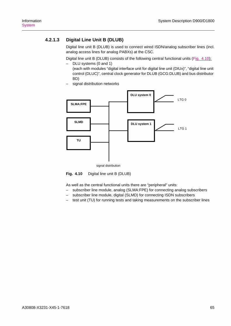
A30808-X3231-X45-1-7618 65
InformationSystem
System Description D900/D1800
4.2.1.3 Digital Line Unit B (DLUB)Digital line unit B (DLUB) is used to connect wired ISDN/analog subscriber lines (incl.analog access lines for analog PABXs) at the CSC.
Digital line unit B (DLUB) consists of the following central functional units (Fig. 4.10):– DLU systems (0 and 1)
(each with modules “digital interface unit for digital line unit (DIUx)”, “digital line unitcontrol (DLUC)”, central clock generator for DLUB (GCG:DLUB) and bus distributorBD)
– signal distribution networks
Fig. 4.10 Digital line unit B (DLUB)
As well as the central functional units there are “peripheral" units:– subscriber line module, analog (SLMA:FPE) for connecting analog subscribers– subscriber line module, digital (SLMD) for connecting ISDN subscribers– test unit (TU) for running tests and taking measurements on the subscriber lines
DLU system 1
DLU system 0
SLMA:FPELTG 0
LTG 1
signal distribution
SLMD
TU

66 A30808-X3231-X45-1-7618
System Description D900/D1800 InformationSystem
4.2.1.4 Switching Network (SN(B))The switching network B (SN(B)) is an especially compact version compared withswitching network (SN).
The SN(B) consists of time stages and space stages. In time stages, octets to beswitched change time slot and highway according to their destination. In space stagesthey change highway without changing time slots.
The parameters of the time and space stages (4I4, 16I16, 8I15, 15I8, Fig. 4.11) alwaysrepresent the number of 8-Mbit/s highways, which have 128 channels each. Connectionpaths through the time and space stages are switched by the switch group controls(SGCB) in accordance with the switching information from the coordination processor(CP113C/CR). The SGCBs respond to commands from the CP113C/CR. The SGCBsalso independently generate the setting data and set the message channels (e.g.between CP113C/CR and the LTG) for data exchange between the distributed controls.
Fig. 4.11 Division of switching network (SN(B)) into time (T) and space (S) stages (showing only one plane ofthe duplicated SN) and range of connection capacity
In its maximum configuration, the SN(B) contains only 5 different types of modules. TheSN can be expanded in small stages by adding plug-in modules and cables and if neces-sary by assigning extra racks. Optimized switching network B configurations are avail-able in a range of sizes.
The SN is always duplicated (planes 0 and 1). Each connection is switched simulta-neously through both planes, so that a standby connection is always immediately avail-able in the event of a failure.
In digital switching networks, the octets being sent in the two directions between thecalling and called subscribers are transmitted separately. This corresponds to a 4-wireconnection in analog systems. Fig. 4.12 shows the basic principles of a connectionswitched through the switching network (with time slots x,y,z).
444 4 81615
min.
max.
Number of
8-Mbit/smultiplex lines
time stages channels permultiplex line
4 1
128
128
1284
x
x
x
x
8 16 15
1
60
0
64
1
128
T TS S S
Channel capacityat the time stage
= 512 channels at64 kbit/s each
= 65,536 channels at64 kbit/s each
1
128
0
64

A30808-X3231-X45-1-7618 67
InformationSystem
System Description D900/D1800
Fig. 4.12 Connection through the SN(B) (simplified)
4.2.1.5 Common Channel Network Control (CCNC)For the exchange of signaling between network nodes in D900/D1800 the ITU-T stan-dardized signaling method No.7 (CCS7) is used (e.g. MSC/VLR PSTN/ISDN;MSC/VLR/ MSC/VLR; MSC/VLR HLR/AC; MSC/VLR EIR; MSC/VLR BSS). By distin-guishing between a message transfer part (MTP) and several user parts (UP) / applica-tion parts (AP) great flexibility is achieved using this signaling system. The UP/AP aredependent on the specific applications (e.g. ISUP = ISDN user part, TUP = telephonyuser part, MAP = mobile application part, BSSAP = BSS application part). The commonMTP functions in a D900/D1800 SSS network are performed by the common channelnetwork control (CCNC). The UP/AP is contained in the software of the correspondingLTG.
A maximum of 112 common signaling channels can be connected via digital data linksto the CCNC . The digital data links run from the LTG over both levels of the duplicatedswitching network and multiplexers to the CCNC. The CCNC is connected by up to two8 Mbit/s lines to the switching network. Between the CCNC and the two switchingnetwork levels 112 channels are available for each of the two transmission directions(112 channel pairs).
These channels carry the signaling information with a bitrate of 64 kbit/s over the twoswitching network levels from and to the LTG.
zz
z
y
x
y
x
TT S or S-S-S
incomingtrunk LTG
outgoingtrunk LTG
z

68 A30808-X3231-X45-1-7618
System Description D900/D1800 InformationSystem
For reasons of high availability the CCNC has a duplicated processor (CCNP), which isconnected via a likewise duplicated bus system with the CP113C/CR. The CCNC(Fig. 4.13) consists of:– up to 30 groups with max. 8 terminal units for signaling channel (30 SILT groups,
SILTG) and– a duplicated processor for the network of the common signaling channels (CCNP)
Fig. 4.13 Common channel network control (CCNC)
4.2.1.6 Coordination Processor (CP113C/CR)The CP113C/CR is responsible for the main database and for configuration and coordi-nation of the distributed microprocessor controls and data transfer between them:– storage and administration of all programs and data of the MSC, VLR, HLR, AC, EIR
or CSC and M-SSP– storage and administration of all programs, exchange, trunk data– processing of received information for routing, path selection, zoning, charges– generation of the security parameter in the security boxes (IOP:AUC in the AC)– communication with operation and maintenance center– supervision of all subsystems, receipt of error messages, analysis of supervisory
result messages and error messages, alarm treatment, error detection, error loca-tion and error neutralization and configuration functions
– handling of the man-machine interface
The CP113C/CR is used in the network nodes of the D900/D1800 SSS. TheCP113C/CR is a multiprocessor and can be expanded in stages.
CP bus system
290290
0 770
Multiplexer
SILT group 0 SILT group 29
CCNP0 CCNP1
CCS over digital data links(signaling forwarded via LTG and both levels of the SN/SN(B)
and vice-versa)
CP 0 CP 1
SN 0 SN 1

A30808-X3231-X45-1-7618 69
InformationSystem
System Description D900/D1800
In the CP113C/CR (Fig. 4.14) two or more identical processors operate in parallel withload sharing. The rated load of n processors is distributed among n+1 processors. Thismeans that if one processor fails, operation can continue without restriction (redundancymode with n+1 processors). The main functional units of the multiprocessor are asfollows:– base processor (BAP) for CP113C basic configuration and CP113CR (which is only
used for MiniSwitch ); for operation and maintenance and call processing– call processor (CAP) for maximum configuration of the CP113C; for call processing
only– common memory (CMY)– input/output controller (IOC)– input/output processors (IOP)
Fig. 4.14 Coordination processor (CP113C/CR)
Other units assigned to the CP113C/CR (Fig. 4.6) are:Message buffer (MB (B)) for coordination of internal message traffic between theCP113C/CR, the SN(B), the LTGs and the CCNC in an SSS node.Central clock generator (CCG (A)) for the synchronization of the SSS node and,where necessary, the network. The CCG(A) is extremely accurate (10-9). It can,however, be synchronized even more accurately by an external master clock (10-11).System panel (SYP) to display system-internal alarms, advisories and the CP113C/CRload. It thus provides a continuous overview of the state of the system. The SYP alsodisplays external alarms such as fire and air-conditioning system failure for example.Local O&M terminals (BCT) for operation and maintenance. There are two versionsof BCT. A BCT-boot version is used for APS installation, recovery and O&M. It isconnected via a V.24 interface and is operated in BMML command level. A BCT-common version is used for common operation, administration and maintenance with agraphical user interface. It is connected via a X.25 interface.
External memory (EM) , e.g. for– programs and data that do not always have to be resident in the CP113C/CR– a mirror image of all resident programs and data for automatic recovery– call charge and traffic measurement data
To ensure that these programs and data are safeguarded under all circumstances, theEM is duplicated. It consists of two magnetic disk devices (MDD). The CP113C/CR alsohas a magneto-optical disk (MOD) or magnetic tape device (MTD) for input and output.
15
IOC3
CMY0
IOC1IOC0CAPnCAP0BAP1BAP0
0
IOP:AUC
CMY1
Periphery, I/O terminals, external memory
IOP IOP IOP IOP IOP:AUC
150

70 A30808-X3231-X45-1-7618
System Description D900/D1800 InformationSystem
4.2.2 Mechanical Design
4.2.2.1 Rack LayoutD900/D1800 SSS uses the modular SIVAPAC packaging system for the mechanicaldesign. Its basic units are:– modules– module frames– racks– rack rows– cables
All modules and cables are of the plug-in type. SIVAPAC reduces the risk of error in theinstallation of D900/D1800-SSS and permits short installation times. Installation testmanuals and acceptance test manuals are provided to aid the operating company incarrying out commissioning and acceptance testing for the D900/D1800-SSS node.• Modules have a standard format and are mounted vertically in the module rack. A
faceplate on the front edge can have front facing connectors and display and controlelements; the rear edge is fitted with spring contact strips, which make contact withthe blade connectors in the module rack. The printed circuit boards are constructedas multilayer boards. Plated through holes connect the individual layers with eachother and the components to the layer. Surface mounted devices (SMD) are usedwhere high packing density, mounting of components on both sides of the circuitboard and optimum heat dissipation are required simultaneously.
• Module racks combine the modules to form a constructional and wiring unit. Amodule rack basically consists of a backplane, assembly rails, side sections andguide bars for the modules. The backplane forms the rear section of the modulerack. It consists of a multilayer board with blade contact strips pressed in to makethe electrical contact. Its contact pins are arranged to project beyond the rear edgeof the backplane so that cable connectors can be plugged in and additional wirewrapped connections made.
• Racks accommodate module racks and auxiliary devices (e.g. current converters).Wide opening doors allow unrestricted access to the built in system components.Simple clamping elements are used to connect the racks together to form a rack rowand also provide electrical connections.The racks can either stand directly on the floor of the system room or on a raisedfloor. The raised floor allows underfloor cabling as well as a direct supply of coolingair to the bottom of the racks. If the racks are arranged without a raised floor a planarcable shelf above the racks is required.
• The cables are of plug-in design: they are manufactured and tested in the requiredlengths and delivered to the site fitted with connectors. During installation the cableconnectors only need to be plugged into the module rack backplane. From theconnector the cables are routed either up to a planar cable shelf or down under araised floor.D900/D1800 SSS installations obtain their supply voltages (48 V or 60 Vdc) fromcentral power supply units. Standard flexible cables and distribution buses carry theoperating voltage to current converters, inverters and tone/frequency generators.
Current converters produce the dc voltages for the electronic circuits, the inverterssupply power to ac operated peripheral equipments (such as printers) and thetone/frequency generators supply the ringing tones.

A30808-X3231-X45-1-7618 71
InformationSystem
System Description D900/D1800
Natural convection removes dissipated heat from the vertically mounted modules in themodule racks. Dissipated heat can be discharged very easily if the racks are set up ona raised floor. In some cases slide in ventilator units in the rack and/or air conditioninghelp to dissipate the heat.
The interface between internal and external lines is the main distribution rack. TheSiemens compact mini distributor for 2 Mbit/s signals meets the requirements of mostoperating companies for space saving technology. It is suitable for all sizes ofD900/D1800 SSS nodes. Its solderless connection technique, mature technical stan-dard and proven cost effectiveness make it an ideal accessory for D900/D1800 SSS.
Examples of rack layout
An SSS node consists of the following racks (R:...), for:• Coordination processor (CP113C/CR)
R:CP113C/CRR:DEVB
• Switching network (SN(B)) message buffer (MB(B)),central clock generator (A) (CCG(A)) and with line/trunk group N (LTGN)R:SNB/MB/LTGN
• Service equipment: analog modems for remote BCT connection,digital announcement system (DAS) and system panel control (SYPC)R:SE
• Line/trunk group N (LTGN), as well as partially equiped with LTGN and LTGGR:LTGN
• Common channel network control (CCNC)R:CCNP/SILTDR:SILTD
• Data service unit (DSU)R:DLU
• Digital line unit B (DLUB)R:DLUB
The following figures show example of rack layout complements.

72 A30808-X3231-X45-1-7618
System Description D900/D1800 InformationSystem
Fig. 4.15 Standard racks of the coordination processor (CP113C) (Maximumcapacity stage)
(CAP4, IOC2, IOP group 2)
(CAP2, IOC0, IOP group 0)
(CAP5, IOC3, IOP group 3 )
(MDD0, MDD1)(MOD0, MOD1)
(CAP3, IOC1, IOP group 1)
F:PIOP(A) 2
F:PIOP(A) 0
F:PBC(A) 0
F:PBC(A) 1
F:PIOP(A) 3
F:PIOP(A) 1
Fan with filter
Fan
(BAP1, CAP1, BCMY1,
(BAP0, CAP0, BCMY0, CMY0)
Fuse panel
R:CP113C(Rack in 8 foot)
(MODEM)
(MTD 1)
(MTD 0)
Fuse panel
R:DEVB(Rack in 8 foot)
Rectifier
F:DEV(F)
(MODEM)

A30808-X3231-X45-1-7618 73
InformationSystem
System Description D900/D1800
Fig. 4.16 Racks for switching network B, message buffer B, central clock generatorA and line/trunk group N(R:SNB/MB/LTGN)
R:SNB/MB/LTGN(Rack in 8 foot)
Sicherungsschiene
F:TSG(B)
(TSG0.x)
F:MB/CCG (B)
F:MB/CCG (B)
F:LTGN (A)
(LTG 0, 1 ... , 15)
Free
F:TSG(B))
(TSG1.x)
Sicherungsschiene
F:SSG(B)
(SSG0.x)
F:MB/CCG (B)
F:MB/CCG (B)
Free
Free
F:SSG(B)
(SSG1.x )
R:SNB/MB/LTGN(Rack in 8 foot)

74 A30808-X3231-X45-1-7618
System Description D900/D1800 InformationSystem
Fig. 4.17 Rack for service equipment: analog modems for remote BCT connection,digital announcement system (DAS) and system panel control (SYPC)
DAS 300/400
Rectifier
DAS 300/400
DAS 300/400
F:Modem
DAS 300/400
F:Modem
Fuse panel
R:SE(Rack in 8 foot)
F:SYPC(A)
Rectifier

A30808-X3231-X45-1-7618 75
InformationSystem
System Description D900/D1800
Fig. 4.18 Racks for line/trunk group N (LTGN), as well as partially equiped withLTGN and LTGG
R:LTGN(Rack with 8 foot)
R:LTGN(Rack with 8 foot)
Free
F:LTGN(A)
Free
F:LTGN(A)
F:LTGN(A)
F:LTGN(A)
Fuse panel
(LTG 0, 1, ... , 15)
(LTG 16, 17, ... , 31)
(LTG 32, 33, ... , 47)
(LTG 48, 49, ... , 63)
Free
F:LTGG(A)
Free
F:LTGN(A)
F:LTGN(A)
F:LTGN(A)
Fuse panel
(LTG 0, 1, 2, ... , 15)
(LTG 16, 17, ... , 31)
(LTG 32, 33, ... , 47)
(LTG 0, 1)

76 A30808-X3231-X45-1-7618
System Description D900/D1800 InformationSystem
Fig. 4.19 Racks for common channel network control (CCNC)
F:SILTD(A)
(SILTD(A) 0)
F:SILTD(A)
(SILTD(A) 1)
F:SILTD(A)
(SILTD(A) 2)
F:SILTD(A)
(SILTD(A) 3)
F:SILTD(A)
(SILTD(A) 4)
F:SILTD(A)
(SILTD(A) 5)
F:CCNP(B)
(CCNP(B) 0)
F:CCNP(B)
(CCNP(B) 1)
F:SILTD(A)
(SILTD(A )1)
F:SILTD(A)
(SILTD(A) 2)
Fuse panel
F:SILTD(A)
(SILTD(A )0)
Fuse panel
R:CCNP/SILTD(Rack in 8 foot)
R:SILTD(Rack in 8 foot)

A30808-X3231-X45-1-7618 77
InformationSystem
System Description D900/D1800
Fig. 4.20 Rack for DSU
F:Modem
F:Modem
Shelf 5
Shelf 4
Shelf 3
Shelf 2
Shelf 1
Shelf 0
F:DLU(A)
F:DLU(B)
F:DLU(B)
R:DLU(Rack in 8 foot)
Fuse panel

78 A30808-X3231-X45-1-7618
System Description D900/D1800 InformationSystem
Fig. 4.21 Rack for DLUB (R:DLUB)
Fuse panel
F:DLUB(D)
F:DLUB(E)
F:DLUB(D)
F:DLUB(E)
R:DLUB(Rack in 8 foot)
up to 1760 analog subscriberup to 768 ISDN subscriber
Shelf 0
Shelf1
Shelf 2
Shelf 3
Shelf 0
Shelf 1
Shelf 2
Shelf 3
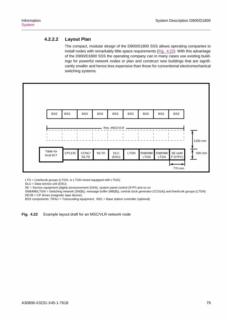
A30808-X3231-X45-1-7618 79
InformationSystem
System Description D900/D1800
4.2.2.2 Layout PlanThe compact, modular design of the D900/D1800 SSS allows operating companies toinstall nodes with remarkably little space requirements (Fig. 4.22). With this advantageof the D900/D1800 SSS the operating company can in many cases use existing build-ings for powerful network nodes or plan and construct new buildings that are signifi-cantly smaller and hence less expensive than those for conventional electromechanicalswitching systems.
Fig. 4.22 Example layout draft for an MSC/VLR network node
1200 mm
500 mmTable forlocal BCT
CP113C CCNC/SILTD
DLU(DSU)
LTGN
Res. MSC/VLR
770 mm
LTG = Line/trunk groups (LTGN, or LTGN mixed equipped with LTGG)DLU = Data service unit (DSU)SE = Service equipment (digital announcement (DAS), system panel control (SYP) and so onSNB/MB/LTGN = Switching network (SN(B)), message buffer (MB(B)), central clock generator (CCG(A)) and line/trunk groups (LTGN)DEVB = CP drives (magnetic tape device);BSS components: TRAU = Transcoding equipment, BSC = Base station controller (optional)
SILTD SNB/MB/LTGN
SNB/MB/LTGN
SE (withF:SYPC)
BSS BSS BSS BSS BSS BSS BSS BSS BSS

80 A30808-X3231-X45-1-7618
System Description D900/D1800 InformationSystem
4.2.2.3 MiniSwitch (Very Compact MSC/VLR Network Nodes, includingContainers)For use in rural switching centers with the need of low space a very compact MSC/VLRnetwork node (MiniSwitch ) is available. Generally the MiniSwitch consists of fourspecial combined 7 foot racks for installation in a building (Fig. 4.23).
Fig. 4.23 Rack layout for a MiniSwitch (example)
The advantageous low space requirements mentioned above also permit installation ofthe MiniSwitch in containers. For protection in transit against mechanical shock, allracks in containers are mounted on vibration absorbers. The 6058 mm (20 foot)container accommodates all facilities and peripheral equipment required for operationof the D900/D1800 SSS.
Rectifier
DAS 300
Fan
(IOC1, IOP group 1 )
(BAP1, BCMY1, CMY1)
F:SMSC(C) 0
F:SMSC(C) 1
F:PIOP(A) 0
F:PBC(A) 0
F:PIOP(A) 1
F:PBC(A) 1
Fan with filter
(BAP0, BCMY0, CMY0)
(IOC0, IOP group 0)
Fuse panel
R:CP113CE
(MTD 0)
Fuse panel
R:DEVB/DSU
Fan with filter
F:DLU(A)
F:MODEM
(MDD0 , MDD1)(MOD0, MOD1)
F:DEV(F)
BCTF:CCNP(B)
(CCNP(B) 1)
F:CCNP(B)
(CCNP(B) 0)
F:SILTD(A)
(SILTD(A )1)
F:SILTD(A)
(SILTD(A) 2)
F:SILTD(A)
(SILTD(A )0)
Fuse panel
R:CCNP/SILTD
F:LTGG(A)
F:LTGN (A)
F:LTGN (A)
F:LTGN (A)
Fuse panel
(LTG 0, 1, ... , 15)
(LTG 16, 17, ... , 31)
(LTG 32, 33, ... , 47)
(LTG 0, 1)
R:LTGN/LTGG
The frame F:LTGG(A) is used toaccommodate a UI-LTG for IN

A30808-X3231-X45-1-7618 81
InformationSystem
System Description D900/D1800
4.3 SoftwareD900/D1800 SSS software is characterized by high quality and reliability, extensivedynamic capabilities (real-time requirements) and flexibility for implementations of addi-tional functions. These characteristics have been achieved in a cost-effective mannerby:– flexible, modular software architecture (Section 4.3.1)– efficient CHILL-based software technology (Section 4.3.2)– consistent software quality assurance (Section 9.2)
4.3.1 Software ArchitectureThe great flexibility of D900/D1800 SSS stems from the extensive use of reloadablesoftware. Only a few processors, namely those with a narrow range of functions and notdependent on the application, such as the switching network and message buffercontrols, contain programs which are stored in read-only memories.
The reloadable software for a D900/D1800 SSS node including the node-specific dataforms the application program system (APS). For reasons of security a current image ofthe APS is held in the duplicated external memory in each D900/D1800 SSS node.
Hardware is subject to rapid technological change. To enable D900/D1800 to profit fromthis evolution, the D900/D1800 SSS software is designed so that only a minimum of itis hardware-dependent.
In accordance with the distributed control within D900/D1800 SSS each processor in thesystem requires its own software. This software is divided into an application-indepen-dent and an application-specific part (Fig. 4.24).
Fig. 4.24 Software shells for a processor
The application-independent part always contains the operating system which is tailoredto the functions of a particular hardware subsystem. The application-specific software –also called the user software – implements the functions for the various applications.The operating system provides all the programs in the user software with a uniformconvenient interface via which they can make use of operating system functions andthus the resources of the processor.
Operating system
Application-inde-pendent software
Hardware
Application-specificsoftware
User software

82 A30808-X3231-X45-1-7618
System Description D900/D1800 InformationSystem
The software of the individual processors normally contains a wide variety of functions.It is accordingly divided into subsystems. Each subsystem generally contains severalmodules. These represent the smallest units for compilation.
The various types of data are an essential component of the D900/D1800 SSS software.The data can be classified according to type, scope, lifetime and storage location. Node-specific data are held in the database of the CP113C/CR. Its size and contents dependon the equipment and the network environment of the node involved. The database ispart of the user software.
The call processing programs control the establishment of connections in accordancewith subscriber requirements. Apart from the appropriate hardware resources, theseprograms require information on the network termination characteristics and the networkenvironment (e.g. for routing). This information has to be provided by the operatingcompany. Man-machine language (MML) commands can be used to incorporate suchinformation into the system and to administer it there. Commands of this type are eval-uated by the administration programs. The call processing programs also providecharge data and traffic data; the administration programs edit these data, save them andoutput them on demand.
Safeguarding and maintenance programs guarantee unimpaired system operation. Thesafeguarding programs are part of the operating system and are executed automati-cally. In contrast, the maintenance programs – like the call processing and administra-tion programs – are user programs. Some of them only run after the appropriate MMLcommands have been entered. They make use of safeguarding program functions.
4.3.1.1 Operating SystemsEach processor in D900/D1800 SSS has its own operating system with capabilitiesdependent on the tasks to be performed by the processor and the resources which itmanages. All operating systems have to perform their functions under real-time condi-tions. They are therefore interrupt-driven and work according to priorities. The coordina-tion processor (CP113C/CR) operating system consists of executive and safeguardingprograms.
Executive programs
The integral parts of the executive programs are:– scheduler– timer administration– memory management– input and output• The scheduler determines the sequence in which the CP113C/CR performs its
tasks. After the start phase this is generally the sequence of events such as inputsor operating system requests. Individual functions or subfunctions are mainlyarranged as processes in the CP113C/CR and are administered by the schedulervia process queues. The processes are assigned different priorities.When an event occurs it generates an interrupt of the process currently executingand activates the scheduler, which then analyses the event sufficiently to determinethe process or program which is to perform further processing. The scheduler thentransfers control to the process with the highest priority which is ready to run. If twoor more processes with the same priority are ready to run, the process which hasbeen waiting the longest is given preference. The interrupt facility, the defining ofprocesses to match the functions performed and the correct assignment of priorities

A30808-X3231-X45-1-7618 83
InformationSystem
System Description D900/D1800
guarantee that the real-time conditions are fulfilled and that the CP113C/CR canrespond to an event within an appropriate time.
• Timer administration allows user programs to set and reset timers. They can thussupervise the correct timing for execution sequences and initiate further activitiesafter a specific time. In addition, the user programs can interrogate timer administra-tion to obtain the current date and time of delay.
• The time-critical part of the CP113C/CR software is always loaded into the memoryunit of the CP113C/CR (resident). The remaining memory (unassigned memory) isavailable for the reloadable software where required. It is allocated and releasedagain by memory management.
• The input and output part of the executive programs controls and supervises theexchange of messages with the call processing periphery (LTG), the commonchannel signaling network control (CCNC) and the operation and maintenanceperiphery, and preprocesses MML commands.
Safeguarding programs
The functions of the safeguarding programs are:– determination of a functional system configuration on start-up and establishing this
configuration– recording and processing safeguarding messages from the periphery and from
CP113C/CR processes– controlling the execution of periodic checks– evaluating alarms from supervision circuits in the CP113C/CR– collecting error symptoms and saving them– analysing and locating errors– reestablishing an operable system configuration after hardware faults, and– rectifying, by means of adequate recovery measures, the effects of software errors
which cannot be neutralized by the user programs themselves
Recovery measures in D900/D1800 SSS are implemented on several levels. The mainlevels are restart, new start and initial start.– Restart only applies to the currently running process and does not affect more than
one connection.– New start resets all processes and affects those connections which are currently
being set up.– Initial start, which involves reloading the entire software, results in the release of all
connections.
The choice of recovery level depends on the type and frequency of the detected soft-ware error. In the first instance, the level that promises success while involving the leastimpairment of normal operation is selected. But if the same error then recurs, the nexthigher recovery level comes into effect (escalation).

84 A30808-X3231-X45-1-7618
System Description D900/D1800 InformationSystem
4.3.1.2 User SoftwareThe user software implements the call processing, administration and maintenancefunctions and the associated database required for the specific application. Newfeatures, e.g. a specific signaling system for trunks, and whole feature packages can beeasily implemented in D900/D1800 SSS by means of appropriate subsystem variants orby adding new subsystems.
Database
The node-specific data stored in the database cover, for instance, the following:
Hardware image– hardware configuration– hardware characteristics– hardware states
Termination characteristics, e.g.– service features– signaling features– grouping of lines (trunk groups)
Data for the establishment of links, e.g. between– equipment number and termination data
Call setup, e.g.– digit translation– routing
Data accumulated during operation, e.g.– charging– traffic measurement
The database contains both transient and semipermanent data. The transient data arelargely call-related and therefore continually being changed by the call-processingprograms during operation. The semipermanent data, on the other hand, describeconditions and characteristics which change relatively seldom during operation, forinstance the system configuration or line characteristics. These data are under writeprotection and their current image is always kept in the external memory. Changes tosemipermanent data are made by entering the appropriate MML commands or bymeans of subscriber input.
A number of modules in the database contain the definitions of the data structures, thedata declarations and the access procedures. Users can only access the data via theseprocedures. Initially, the data fields are only small, their ultimate size depending on thecapacity and port assignments of a particular node. A utility program is employed toexpand the data fields to meet the planned requirements. The database can beextended while the system is in operation.
In accordance with the distributed control principle employed in D900/D1800 SSS,images of parts of the database are also found in peripheral processors such as thegroup processors and the common channel signaling network control.
Call processing programs
In the coordination processor the call processing programs, e.g. for the MSC/VLRnodes, only handle those call processing functions which require access to data avail-able only to the CP113C/CR:– reading and analysis of call and network termination data

A30808-X3231-X45-1-7618 85
InformationSystem
System Description D900/D1800
– digit translation with the following functions:destination routing with possible route processingcharge zone determination
– path selection in the switching network image and sending of setting commands tothe switching network control
– sending of messages to the group processors with the objective of initiating specificactions and transferring to the group processors the information required for furtherindependent call processing
The call processing programs in the group processors (GP/GPN) deal with most of theircall processing tasks without involving the CP113C/CR. They are activated by callprocessing events from the LTG periphery, commands from the CP113C/CR, reportsfrom other GP/GPNs and order from the CCNC. Event and message processing activi-ties of the GP/GPN are as follows:– timing supervision– evaluation of call data and network termination data– modification of call data and transient network termination data– identification of signals– sending of messages to the CP113C/CR, reports to other GP/GPNs, or order to the
CCNC– seizure and release of traffic channels– standardization of signaling before informing the CP113C/CR or another GP/GPN
(physically different signals from different signaling procedures with identical mean-ings are converted into uniform internal messages)
– control of signaling– pre-analysis of dialed digits– execution of service-feature specific activities (provided no central coordination is
required)– sending of setting commands to the group switch– generation of charge statistic and traffic data
Administration programs
The CP113C/CR administration programs process the administrative MML commands.Activities required here are as follows:– incorporation of data into the database– modification of data in the database– reading and editing data in the database for output– using appropriate messages to pass information to the peripheral processors,
(GP/GPN, CCNP) concerning data modification– control of traffic measurement processes in the CP113C/CR– activation of measurements (traffic and statistics) in the periphery
In addition the administration programs save charge, statistics and traffic data in theexternal memory. These are obtained from the call processing programs in theCP113C/CR or supplied by the administration programs of the peripheral processors.
The administration programs of the peripheral processors (GP/GPN and CCNP)process the messages from the administration programs of the CP113C/CR. Inresponse they:– inform other peripheral processors– modify their own data (partial image of the database)– start or end measurements (statistics and traffic)– transfer data to the CP113C/CR

86 A30808-X3231-X45-1-7618
System Description D900/D1800 InformationSystem
Maintenance
The CP113C/CR maintenance programs process the MML commands that are essen-tial to the provision of trouble-free service. Among the activities required here are:– control of configuration and recovery processes with the aid of safeguarding
programs– control of measurement and testing processes for the trunk network– control of fault analysis and diagnostic processes– initiation of configuration, recovery, testing, measurement and diagnostic activities
in peripheral processors using the appropriate commands
In addition they process messages containing measurement, testing and diagnosticresults from the LTGs (GP/GPN). Another function of the maintenance program is todisplay faults on the system panel and provide audible signals for them where neces-sary.
The maintenance programs of the GP/GPN process:– commands from maintenance programs in the CP113C/CR– results from test equipment for trunks in the LTGs– messages from supervision equipment and supervision programs in the LTGs (e.g.
trunk maintenance)
Possible GP/GPN reactions are as follows:– sending control messages to test equipment– starting test and diagnostic procedures– executing configuration measures– sending messages to the CP113C/CR
4.3.2 Software TechnologyThe D900/D1800 SSS software technology is characterized by:– a software engineering production plan (SEPP)– powerful standardized description and implementation languages (SDL, CHILL)– extensive and convenient hardware and software support (support software also
based on CHILL)
4.3.2.1 Software Engineering Production PlanThe D900/D1800 SSS software is developed in accordance with a software engineeringproduction plan (SEPP). It ensures a uniform and systematic approach and thereforeguarantees cost-effective development, complete documentation and above all high-quality software.
4.3.2.2 Description and Implementation LanguagesAn important design aid for D900/D1800 SSS software is the specification and descrip-tion language (SDL) standardized by the ITU-T. It is particularly suitable for providingunambivalent descriptions of processes and execution sequences which are character-ized by states, events and by the ensuing actions and state transitions. TheD900/D1800 SSS development environment allows the developers to design, modifyand administer computer-aided SDL diagrams and their graphic symbols. The SDLdiagrams are the basis for coding in CHILL or Assembler. A special software tool allowsAssembler code to be generated directly from the SDL logic.

A30808-X3231-X45-1-7618 87
InformationSystem
System Description D900/D1800
CHILL
The source modules of the D900/D1800-SSS software are largely written in the ITU-Tstandard high-level language CHILL. CHILL guarantees both structured programmingand modular structure. Software written in CHILL is to a large extent self-documenting,easy to read, easy to expand and easy to maintain. CHILL as a modern high-levelprogramming language is the basis for the extensive portability of D900/D1800 SSSsoftware. This means that software written in CHILL can be run on commercial dataprocessing systems as well as on D900/D1800 SSS coordination processors.
In contrast to many other programming languages, CHILL provides specific facilities fordeclaring data types (modes) and structures. This allows interfaces to be preciselydefined and automatically checked. This is extremely important in a project where morethan one thousand software modules have to be linked together to an applicationprogram system (APS).
4.3.2.3 Support SoftwareEfficient development and quality of software are greatly influenced by the support avail-able. For D900/D1800 SSS software development, commercial computer systems,personal computers and switching processors are used. Commercially available soft-ware is only able to support development activities to a limited extent. An extensivepackage of D900/D1800 SSS support software is therefore needed to support rapiddevelopment, production and updating of application program systems. This software,including the CHILL compiler, is written in CHILL and is thus portable. It supports allphases of D900/D1800 SSS software development from analysis to application.

88 A30808-X3231-X45-1-7618
System Description D900/D1800 InformationSystem
5 Base Station System (BSS)
5.1 System Architecture
5.1.1 Network ElementsThe base station system (BSS) and the corresponding operation and maintenancesubsystem (OMC-B) form the Siemens base station system (SBS). The base stationsystem (BSS) consists of base station controllers (BSCs), base transceiver stations(BTSs) integrated in BTS equipments (BTSEs), transcoding and rate adaption units(TRAUs) and local maintenance terminals (LMTs) as shown in Fig. 5.1. The structurewith an intelligent centralized controller part and several low cost transceiver stations iswell appropriate to both smallest cell networks, as preferably used in urban areas, andlarge-cell rural networks. The advantage of smallest cell networks is the internalhandover offered by the BSCs, the advantage of large-cell networks is the coverage oflarge areas by low-cost BTSs.
Fig. 5.1 Structure of the D900/D1800 BSS
TTµ
(from/to OMC-B via MSC,with PCM30 NUCs))
T
BTSE BSC
(from/to OMC-B, withX.25/PSDN)
BTS
remote
TRAU
BTS
remote
BTS
together withBSC
(from/to MSC)
LMT LMT
Abis
Um
Um
Um
Asub
A
O
Abis
LMT
T
(Interface to anexternal CBC)
LMT

A30808-X3231-X45-1-7618 89
InformationSystem
System Description D900/D1800
Base transceiver station equipment (BTSE)
BTSEs are distributed over the whole radio service area. Each BTSE supports generallymore BTS but at least one BTS. Each BTS serves a radio cell.
Base station controller (BSC)
One or more BSCs are linked to an MSC. Physically the BSCs can be grouped togetherat a central point on MSC sites or remotely in a shelter or in a confined space. The BSCcan then act as a concentrator for the links between the Abis and Asub interfaces. ABSC serves one or more BTSs.
Transcoding and rate adaption unit (TRAU)
Although the TRAU is logically part of the BSS it is designed to be physically located atthe MSC site. This helps to save transmission capacity on the Asub-interface (refer toSection 5.1.2).
5.1.2 InterfacesThe interfaces shown in Fig. 5.1 are defined as follows.
A-Interface
The A-interface is the interface of the TRAU towards the MSC. The interface comprisestraffic channels and as signaling link the common channel signaling No.7 (CCS7)system. See also SSS interfaces in Section 4.1.3.
Asub-interface
The Asub-interface is the interface from the TRAU to the BSC. The interface comprisestraffic and control channels. Submultiplexing of the traffic channels (4 x 16 kbit/s on a 64kbit/s channel) is generally applied.
Abis-Interface
The Abis-interface is the interface of the BSC towards the BTSs. Physical transmissionis realized with 2048 kbit/s or multiples of 64kbit/s. Submultiplexing is performed withfull-rate channels for 8 traffic channels onto 2 x 64-kbit/s and with half-rate channels for16 traffic channels onto 4 x 64 kbit/s or 2 x 64 kbit/s. Even if the BSC and the BTSs arecollocated the Abis-interface is implemented.
O-Interface
The O-interface is the interface of the BSC towards the OMC-B. It is a packet-switcheddata network (PSDN) interface based on the X.25 interface specification of the ITU-T .Optional the O&M connections from OMC-B to BSS network elements can be handledby PCM30 nailed-up connections (NUCs) via MSC.
Interface from BSS to (an external) CBC
The interface to an external cell broadcast center (CBC) provides the possibility ofconnecting an external CBC of any vendor. This interface is an X.25 one.

90 A30808-X3231-X45-1-7618
System Description D900/D1800 InformationSystem
T, Tµ Interface
The T interface is the interface of the BSC, BTS and TRAU towards the LMTs. It is alsobased on the X.21/V.11 interface specification of the ITU-T. The Tµ interface is thespecific interface of the BS-11 BTS. It is based on RS232/V.24 interface specification ofthe ITU-T.
Um-Interface (GSM radio interface)
The Um-interface is the GSM radio interface between the BTS(-antenna) and the GSMmobile stations. This interface provides a number of logical channels. Mobile user infor-mation (voice, data) is transmitted via traffic channels, control signals and shortmessages are transmitted via control channels. Such control channels are:– broadcast channels
for frequency correction, synchronization– common control channels
for paging, random access and access grant– dedicated control channels
for slow associated control, fast associated control and stand-alone control• Radio frequency channels and bands of D900
The D900 provides the GSM900 primary band (890-915 MHz for uplink, 935-960MHz for downlink) as well as the GSM900 extended band G1 (880-915 MHz foruplink, 925-960 MHz for downlink). The radio channel assignment for the D900 BSS(GSM900 primary band) is shown in Fig. 5.2, and (GSM900 extended band G1) isshown in Fig. 5.3.
Fig. 5.2 Radio channel assignment for the D900 BSS (GSM900 primary band)
Fig. 5.3 Radio channel assignment for the D900 BSS (GSM900 extended band G1)
BSS receiver channel numbers(uplink)
BSS transmitter channel numbers(downlink)
Radio frequencychannel spacing 200 kHz
Radio frequencychannel spacing 200 kHz
001 002
890 890.2 MHz
123 124
914.8 915 935 960
124123001 002
935.2 959.8MHz
Duplex spacing 45 MHz
889.8
BSS receiver channel numbers(uplink)
BSS transmitter channel numbers(downlink)
Radio frequencychannel spacing 200 kHz
Radio frequencychannel spacing 200 kHz
001 002
890 890.2 MHz
123 124
914.8 915
Duplex spacing 45 MHz
880 880.2
975 1023 001 002 123 124975 1023
934.8 935 935.2 MHz 959.8 960925 925.2
000 000

A30808-X3231-X45-1-7618 91
InformationSystem
System Description D900/D1800
BTSs of adjacent cells use non-adjacent radio channels in order to avoid mutual inter-ference. The mobile stations can use any pair of the 124 (174 for extended band G1)radio channels on the uplink or on the downlink. The decision as to which frequency pairis used for a particular connection is taken by the BSC and transmitted to the mobilestation as a radio command via a signaling channel.
• Radio frequency channels and bands of D1800The D1800 provides the GSM1800 frequency band (1710-1785 MHz for uplink,1805-1880 MHz for downlink). The radio channel assignment for the D1800 BSS isshown in Fig. 5.4.
Fig. 5.4 Radio channel assignment for the D1800 BSS
BTSs of adjacent cells use non-adjacent radio channels in order to avoid mutual inter-ference. The mobile stations can use any pair of the 374 (absolute radio frequencychannel 512 ... 885) radio channels on the uplink or on the downlink. The decision as towhich frequency pair is used for a particular connection is taken by the BSC and trans-mitted to the mobile station as a radio command via a signaling channel.• Time division multiplex access (TDMA) frame
Present-day PLMNs employ a type of frequency division multiple access ( FDMA) inwhich each traffic or control channel is related to one radio channel. Each radiochannel pair in this case requires one transmitter and one receiver. The radio chan-nels are separated by analog filters.The D900/D1800 system employs a combination of frequency division multipleaccess (FDMA) and time division multiple access (TDMA) with eight traffic or controlchannels displaced in time and transmitted via one radio channel. With full-ratechannels only one transmitter and one receiver are required for 8 traffic or controlchannel pairs (with half-rate channels for 16). This results in reduced space andenergy requirements in the base transceiver stations (BTSs).A TDMA frame is shown in Fig. 5.5 .
iD900 for European Railways: With the services required by the European RailwayConsortium, the SBS (BSS + OMS-B) platform becomes able to provide service to MSsworking in the GSM-R frequency band (876-880 MHz for uplink and 921-925 MHz fordownlink). This opens to the future introduction of the advanced speech call items(ASCI) services currently being specified by ETSI in their Phase 2+.
BSS receiver channel numbers(uplink)
BSS transmitter channel numbers(downlink)
Radio frequencychannel spacing 200 kHz
Radio frequencychannel spacing 200 kHz
512 513
1710 1710.2 MHz
884 885
1784.8 1785 1805 1880
885884512 513
1805.2 1879.8MHz
Duplex spacing 95 MHz

92 A30808-X3231-X45-1-7618
System Description D900/D1800 InformationSystem
Fig. 5.5 Time division multiplex access (TDMA) frame of the GSM radio interface ofthe BSS
Each radio channel is time multiplexed. The nature of TDMA communication makes the200-kHz transmission bandwidth available to 8 full-rate channels or 16 half-rate chan-nels, not all at the same time but at intervals (time slots) repeated in a fixed pattern.
The time slots of a particular time slot number carry the signals of one traffic or controlchannel. These signals are split into portions, compressed to about one eighth of theirduration and then entered into a selected time slot. After the radio transmission thecompressed time portions are picked up from the time slots, regenerated by expandingthem to their original duration, and finally put together to form the original signal.
In the case of voice transmission the electric analog voice signals produced by themicrophone are initially converted for full-rate channels into a 13 kbit/s bit stream (forhalf-rate channels into a 6.5 kbit/s bit stream) in a voice encoding process developedespecially for digital PLMNs. In order to enhance the noise immunity of the informationto be transmitted, the process also provides an error control (forward error correction),allowing the transmitted information to be reconstructed to a certain extent at thereceiver, even if the transmission path is disturbed. This increases the bit rate for full-rate channels to 22.8 kbit/s (for half-rate channels to 11.4 kbit/s).
In addition, the information bits are interleaved and separated at the transmitter andreceiver respectively, to cope with error bursts occurring on the radio path. Additionalsynchronizing and control information and transmission-free intervals between the timeslots further raise the bit rate to a total of 33.9 kbit/s. The transmission rate for the overallTDMA signal is eight times as high, i.e. about 270 kbit/s. The modulation method imple-mented is called gaussian minimum shift keying (GMSK).
A TDMA frame corresponds to 1250 bits transmitted in 120/26 ≈ 4.615 ms, a time slotcorresponds to 156.25 bits transmitted in 15/26 ≈ 0.577 ms.
≈ 0.577 ms(156.25 bits)
Time slotnumber (tsn)
tsn 7
tsn 6
tsn 5
tsn 4
tsn 3
tsn 2
tsn 1
tsn 0
1 TDMA frame≈ 4.615 ms(1250 bits)
200 kHzradio channel
1 Time slot
Frequency
Time

A30808-X3231-X45-1-7618 93
InformationSystem
System Description D900/D1800
• Time slot structureThe time slots may carry different kinds of bursts: frequency correction, synchroni-zation, access, dummy, and normal bursts. A burst is a period of the radio frequencycarrier which is modulated by a data stream. The modulation is applied for the usefulduration of the burst. In general, the useful duration of the burst is the duration equiv-alent of 147 bits (from 0.5 to 147.5 bit time equivalent), except the access burst,which has a useful duration equivalent of 87 bits (from 0.5 to 87.5 bit time equiva-lent). A burst represents the physical content of a time slot. The bit with the lowestbit number (bn) is transmitted first. In order to minimise interference the mobilestation is required during the guard periods (GPs) to attenuate its transmissionamplitude and to adjust possible time shifts and the amplitudes of the bursts.Frequency correction bursts are used by the mobile station to adjust its receiver andtransmitter frequencies. Synchronization bursts are used to establish an initial bitand frame synchronization. The access burst has an extended guard period whichhelps to control the time lag of the signals due to the initial distance between mobilestation and BTS which can be up to 35 km. Once the time lag has been corrected,the delta time lag resulting from the alteration of distance of a moving mobile stationis controlled with the aid of the normal guard periods of 8.25 bit durations. Thedummy burst is applied if the message queue is empty. The structure of a normalburst is shown in Fig. 5.6.
Fig. 5.6 Time slot with a normal burst
The training sequence in the normal burst has 26 bits which represent the unchangeablesynchronization pattern. This is enough to maintain the bit and frame synchronizationonce it has been found with the synchronization and the access bursts. The encryptedbit part of the normal burst is 2 x 58 bits.
Eight different training sequences have been defined. Neighboring radio cells (BTSantennas) are assigned different training sequences so that they can be distinguishedby the mobile station.• Frame structure
The frame structure is shown in Fig. 5.7.
2 144 145 14786603 8761bn
Encrypted bits58
Training sequence bits26
Encrypted bits58
TB3
bn = bit number, GP = guard period (8.5 bit time equivalent), TB= tail bit
GP8.25
TB3

94 A30808-X3231-X45-1-7618
System Description D900/D1800 InformationSystem
Fig. 5.7 Frame structure of the radio interface of the BSS
Traffic channels and control channels comprise different numbers of multiframes: 51multiframes in the case of traffic channels, 26 multiframes in the case of control chan-nels. Because the numbers 51 and 26 have no common measures (except the trivialdivisor one), traffic and control channels can be active simultaneously at any time, evenif their carrier frequencies are different.
1 TDMA frames = 8 time slots= 1250 bit durations (4.615 ms)
1 multiframe = 51 TDMA frames= 63,750 bit durations (235.385 ms)
1 multiframe = 26 TDMA frames= 32,500 bit durations (120 ms)
1 superframe = 51 multiframes= 1,657,500 bit durations (6.12 s)
8.25 bit3 bit58 bit26 bit58 bit3 bit
(e.g. normal burst)1 bit duration ≈ 3.69 µs
Burst = 1 time slot = 156.25 bit durations (0.577 ms)
tsn 5 tsn 6 tsn 7
0 1 24 25 0 1 49 50
1 superframe = 26 multiframes= 1,657,500 bit durations (6.12 s)
tsn 0 tsn 1 tsn 2 tsn 3 tsn 4
TRAFFIC CH.
CONTROL CH.0
0 1 48 49
1
2 50
2524
3 47
1 hyperframe = 2048 superframes (3 h 28 m 53 s 760 ms)
0 1 2046 20472 3 204520444

A30808-X3231-X45-1-7618 95
InformationSystem
System Description D900/D1800
5.2 Hardware
5.2.1 Hardware ArchitectureThe BSS consists of– base transceiver station equipments (BTSEs)– base station controllers (BSCs)– transcoding and rate adaption units (TRAUs)
and and as described in Section 5.1 and shown in Fig. 5.1. A maximum of 60 BTSEs(sites) or 120 radio cells or 120 carriers can be connected to one BSC.
5.2.1.1 Base Transceiver Station Equipment (BTSE) BS-2x and BS-6x
The BS-2x and BS-6x BTSE is controlled by the base station controller (BSC), to whichit is connected via the Abis-interface. The BS-2x and BS-6x BTSE may be eitherremotely located or colocated with the BSC. The traffic channels set up in the differentBTSEs are switched transparently to the transcoding and rate adaption unit (TRAU)which - although part of the BSS - will usually be remotely located at the MSC site.
The BTS is defined by GSM standard as a network component which serves one cell,the latter in turn being defined by one distinct base station identity code (BSIC) from themobile station point of view.
The hardware architecture of the logical BTS is such that it is possible to serve with onephysical BTSE several logical BTSs (sector radio cells). This reduces equipment costsby sharing central BTSE hardware equipment.
The BS-2x and BS-6x BTSE normally is connected by one or more 2048 kbit/s PCMlinks, so-called Abis-interface to the BSC. Each BS-2x and BS-6x BTSE rack isconnected to the Abis-interface by means of a line interface, which converts the externalPCM signal into an internal data link called bus2 and bus1. Within each BS-2x and BS-6x BTSE rack bus1 connects the transceiver to the other BTS functional blocks.
The BS-2x and BS-6x BTSE (with separate TX and RX paths) consists of thefollowing functional blocks (Fig. 5.8):• BTSE control• Link interface• Transceiver
– baseband & signal processing– transceiver and processor– power amplifier
• TX combiner (HYCOM, FICOM)• RX pre-amplifier (RXAMOD)• RX splitter (RXMUCO)
The BS-2x and BS-6x BTSE (with duplex equipment) consists of the following otherfunctional blocks within the TX and RX path (Fig. 5.9 and Fig. 5.10):• Duplex combiner (DUCOM) or Duplexer and low noise amplifier module (DULAMO)• Receiver antenna module and multi coupler (RXAMCO)
iIn this Section the “standard” type BTS equipments (BS-2x and BS-6x) are described.The micro BTS equipment (BS-11) is described in the following Section.

96 A30808-X3231-X45-1-7618
System Description D900/D1800 InformationSystem
Fig. 5.8 Functional structure of the BS-2x and BS-6x BTSE (with separate TX and RX paths)
Fig. 5.9 Functional structure of the BS-2x and BS-6x BTSE (with duplex combiner (DUCOM))
Transceiver
T interface
Diversity (optional)
Abisinterface
TX combiner(HYCOM/FICOM)
Transceiverand
processor(TPU)
BTSE
RX splitter(RXMUCO)
RX pre-amplifier
(RXAMOD)
TX antenna
RX antenna
RX antenna
Poweramplifier
Bus1
Link interface(LI)
BTSEcontrol
Bus2
LMT
BSC
External alarms
External control
RX splitter(RXMUCO)
RX pre-amplifier
(RXAMOD)
Baseband&signaling
Diversity (optional)
TX/RX antenna
TX/RX antenna
Transceiver
T interface
Abisinterface
TXFIL/
RXFIL
Transceiverand
processor
BTSE
Poweramplifier
Bus1
Link interface(LI)
BTSEcontrol
Bus2
LMT
BSC
External alarms
External Control
RXAMCO
Baseband&signaling
TXFIL/
RXFIL
RXAMCO
Poweramplifier
Duplexcombiner(DUCOM)

A30808-X3231-X45-1-7618 97
InformationSystem
System Description D900/D1800
Fig. 5.10 Functional structure of the BS-2x and BS-6x BTSE (with Duplexer and LNA module (DULAMO))
BTSE control
The BTSE control is represented by the core controller (CCTRL) which controls all O&Mtasks of an entire BTSE and controls all radio cells (BTS) belonging to one BTSE site.The CCTRL is installed a single time in the master rack.
Link interface
The link interface (LI) extracts the network clock information for the common clockgenerator and passes all BTSE relevant data to bus2. It provides on OSI layer 1 aPCM30 link to the BSC (Abis-interface). The physical part of the LI may change,depending on the transmission link type which must be supported on the Abis-interface.
Baseband & signal processing
This functional block is represented by the baseband and signal processing unit(BBSIG) which receives the traffic channel from the link interface via bus2 and receivesOSI layer 3 messages via bus1. It encodes, encrypts and interleaves signalling and userdata in accordance with the channel type used and executes pre-processing of uplinkmeasurements and measurement reports sent from mobile station (MS) and performspower control and handover recognition.
Transceiver and processor
The transceiver is represented by the transceiver and processor unit (TPU) whichconsists of two main blocks, the TRXA and the TRXD. The TRXA part contains all theanalogue signal processing parts and has a transmit and receive part. The TRXD partcontains all the digital signal processing parts.
Diversity (optional)
TX/RXantenna
TX/RXantenna
Transceiver
T interface
Abisinterface
Transceiverand
processor
BTSE
Poweramplifier
Bus1
Link interface(LI)
BTSEcontrol
Bus2
LMT
BSC
External alarms
External Control
Baseband&signalingRXAMCO
orRXAMCO
Duplexer andLNA module(DULAMO)
RXAMCOor
RXAMCO
TXFIL
RXFIL LNA
TXFIL
RXFIL LNA
ACOM

98 A30808-X3231-X45-1-7618
System Description D900/D1800 InformationSystem
Power amplifier
The power amplifier (PA) provides the required RF power in the downlink path. Thereare separate low power and high power PA modules for the frequency bands of D900and D1800. For D900/D1800 there are a low power version and a high power version.
TX antenna combiner (ACOM)
There are two following kinds of TX antenna combiner (ACOM):• Hybrid combiner (HYCOM)
Hybrid combiner (HYCOM) can be divided in two parts. One part is the hybridnetwork which uses a hybrid combining technique useable for up to 4 carriers. Theother part is the transmit antenna module (TXAMOD) which consists of a transmis-sion band filter and a directional coupler.The transmission band filter provides the required suppression of intermodulationproducts outside the transmit band, and protects the receiver against TX phasenoise and spurious emission impacts.HYCOM can be used with baseband frequency hopping and with sythesizerfrequency hopping.
• Filter combiner (FICOM)Filter combiner (FICOM) are remote tunable and enable a combination of up to 6carriers in a rack. FICOM can only be used with baseband frequency hopping.
RX pre-amplifier (RXAMOD)
The RX pre-amplifier is represented by the receiver antenna module (RXAMOD) whichis the first part of the receiver. It can be mounted near to the receiving antenna, andtherefore is of upmost importance for the receiver performance.
The content is a band filter for the whole receiving band (RXFIL), and a 2-branch low-noise preamplifier.
The parallel architecture provides, in case of malfunction of one low-noise amplifier, adegraded but ongoing operation of the BTSE.
RX splitter (RXMUCO)
The RX splitter is represented by the receiver multi coupler (RXMUCO) which providesa multicoupler for the rack internal distribution of the received signals. The multicouplerconsists of an amplifier and a splitter.
Duplex combiner (DUCOM)
The duplex combiner (DUCOM) can be divided in two main parts. One part is a band-pass filter for the transmit path (TXFIL) and a bandpass filter for the receiving path(RXFIL).
Duplexer and noise amplifier module (DULAMO)
The DULAMO consists of a duplexer section (with TXFIL and RXFIL) and a low noiseamplifier (LNA). It provides the means to have simultaneously with every type of antennacombiner two antennas per radio cell, a LNA close to the antenna and to take advantageof “on air combining”. DULAMO can be utilized with every type of antenna combining(FICIOM, HYCOM, DUCOM).

A30808-X3231-X45-1-7618 99
InformationSystem
System Description D900/D1800
Receiver antenna module and multi coupler (RXAMCO)
The receiver antenna module and multi coupler module (RXAMCO) amplifies the RXsignal with low noise figure and splits the RX signal into four receiving signals, plus aseparate high level output.
5.2.1.2 Base Transceiver Station Equipment (BTSE) BS-11
The BS-11 BTSE (micro BTS) is a compact module with a high level integration. Theinner cards are in limited number and are not individually replaceable in the field.
The BS-11 BTSE consists if the following functional blocks– transceivers (TRX1, TRX2)– site manager (SMU)
Fig. 5.11 and Fig. 5.12 show the functional structure of the BS-11 BTSE (micro BTS),whereas Fig. 5.11 shows the 2-TRX micro BTS with integrated antennas and Fig. 5.12shows the 2-TRX micro BTS with external antennas.
Fig. 5.11 Functional structure of the BS-11 BTSE (with integrated antennas)
iHere only the HW architecture of the BTS equipment (BS-11) is described. It is alsocalled micro BTS. It is obviously different to the architectural concept used in theprevious “standard” type BTS equipments, which are described in the Section before.
BS-11BTSE
SMU
MBBCU
MBBCU
RFTX
RFTX
RFRX
RFRX
PA
PA TXfilter
TXfilter
LNA&BF
LNA&BF
RXfilter
RXfilter
TRX1
TRX2
Abis

100 A30808-X3231-X45-1-7618
System Description D900/D1800 InformationSystem
Fig. 5.12 Functional structure of the BS-11 BTSE (with external antennas)
Transceiver (TRX)
The transceiver is composed of the following modules:– power amplifier (PA)– radio frequency transmitter unit (RFTX)– low noise amplifier & band filter (LNA&BF)– radio frequency receiver unit (RFRX)– multichannel base band unit (MBBCU)
The main functions of the power amplifier (PA) are output band-pass filtering in thedefined band, max. output power control, RF power amplifier mixer gain, antennaVSWR alarms and overheating sensor. The output power of the micro BTS always isbelow 2 W (D900) or 3 W (D1800).
The main functions of the radio frequency transmitter unit (RFTX) are reception fromMBBCU unit of the 270 kbit/s modulating signal, direct GMSK modulation in the definedfrequency band, FR frequency hopping, static power control (downlink), dynamic powercontrol, system timings generation and RF carriers reference clock generation.
The main functions of the low noise amplifier & band filter unit (LNA & BF) are selectionof the proper RX band, and amplification of the input signal by means of a low noiseamplifier.
The main functions of the radio frequency receiver unit (RFRX) are reception of radiosignal from LNA/Band filter, conversion of radio signal to a first intermediate frequencyand AGC control.
The multichannel base band unit (MBBCU) is the unit dedicated to the management ofthe 8 (full-rate) or 16 (half-rate) channels carried by the GSM TDMA frame.
Site manager (SMU)
The site manager unit (SMU) is the interconnection element between the transceiversand BSC. Two interface versions of the SMU exists, depending on the type of line inter-face required.
BS-11BTSE
SMU
MBBCU
MBBCU
RFTX
RFTX
RFRX
RFRX
PA
PA
LNA&BF
LNA&BF
Duplexer
TRX1
TRX2
Abis
Duplexer

A30808-X3231-X45-1-7618 101
InformationSystem
System Description D900/D1800
The main SMU functional blocks are the site manager processor (SMU card) and thecombined line interface SMU combo card (SMUCB). The main functions of the sitemanager processor are to manage two 16 or 64 kbit/s HDLC links to/from BSC and toprocess a signaling connection to/from BSC both for radio signaling and O&M signaling.The SMU combo card provides two PCM30 interfaces (or N x 64 kbit/s) with 2048 kbit/sand two ISDN basic access (ISDN BA) interfaces with 144 kbit/s. The selection betweenthe two line SMU interface versions is made by software through the local maintenanceterminal (LMT).
The providing of additional ISDN BA interface is an extremely flexible means thatSiemens provides to its customers especially when the micro BTS is placed in a locationwhere no classical infrastructure (i.e. PCM lines) can be used, e.g. microwave in indoorapplications (hotel lobbies).
Operators evolution to microcells
Introduction of microcells has to be rather regarded as an evolutionary than a revolu-tionary step, because micro-cellular networks rely on the fundamentals of hierarchicalnetwork architecture. This hierarchical network architecture in turn evolves from thevarious operator network evolution & optimization phases, which represent an ongoingand continuous process during network roll-out. Today operators are concerned with theoptimization of their embedded network base and look for mature product solutions toaddress their needs and to flatten the way to a broader and more flexible network as agoal in future.
The above referred to ultimate goal is the deployment of so-called microcells of cell radiitypically < 300 m. This is a matter that requires cost efficient technology which conse-quently assumes an optimized hardware & software platform to the one implementedtoday.
Applications of BS-11 BTSE (micro BTS)
The BS-11 BTSE product can be universally used especially in those applications andspots not reached before. Clear advantages are sensed particularly concerning volumewhen compared to conventional first and second generation products of SBS baseline.
This leads to new application segments primarily in urban and suburban areas:– airports– touristic sites, e.g. natural parks– shopping malls– train stations– hotel lobbies– conference halls– exhibition halls– hot spots, e.g. central business districts– street tunnels
Typical rural deployment of the BS-11 BTSE is also easy thanks to specific outstandingcharacteristics deemed as prerequisites for deployment in rural applications e.g. lowpower consumption and the flexibility in terrestrial network interconnection as well as thevarious power classes offered by the BS-11 BTSE product.
The BS-11 BTSE concept bears in mind economy and features suitability for realizationof enhanced and cost efficient micro-cellular networks. This is especially mirrored in siteacquisition advantages, installation and serviceability objectives of the BS-11 BTSE.

102 A30808-X3231-X45-1-7618
System Description D900/D1800 InformationSystem
5.2.1.3 Base Station Controller (BSC)The BSC is the central component of the BSS. Fig. 5.13 shows the functional structureof the BSC. The BSC supports as well full rate as half rate operation. A half rate upgradehas impact to all main functional parts of the BSC.
Fig. 5.13 Functional structure of the BSC
The BSC consists of– BSC control– line interface– switch unit
BSC control
The BSC control is a multiprocessor system. It contains two main processors performingcall processing and O&M tests, and a set of slave processors for peripheral tasks andfor the communication between the components of the BSS. To achieve a high degreeof reliability, the main processors are duplicated. As a background storage device a harddisk is provided.
One of the two main processors is the so called administrative processor representedby the main processor control card (MPCC), which controls the connections of theswitching unit on the basis of the telephony processor messages. The other of the twomain processors is the so called telephony processor represented by the telephony anddistributor processor card (TDPC), which is responsible for message exchange with theother network entities via the peripheral pre-processors.
There are two types of peripheral processors. One of them is the peripheral processorfor LAPD channels (PPLD) which is responsible for handling the OSI level 2 LAPDprotocol (used for signaling on the Abis- and Asub-interfaces). The other type is theperipheral processor for CCS7 (PPCC), which handles CCS7 MTP OSI layer 2 for thesignaling towards the MSC (A-interface, via Asub-interface).
Operation and maintenance functions of the BSS can be accessed remotely via a dedi-cated interface (O-interface) towards an operation and maintenance center for BSS
Abis-interface
Asub-/A-interface
T interface (V.11)
O interface (X.25)
Lineinterface
Switchunit
Lineinterface
BSC control
BSC
TRAU
LMT
BTSE
OMC-B
ext. CBC interfaceext. CBC

A30808-X3231-X45-1-7618 103
InformationSystem
System Description D900/D1800
(OMC-B). Additionally, a local maintenance terminal (LMT) may be connected allowingfor operation at the BSC on site. For this there is the O&M interface (IXLT), which allowsthe main processor control card (MPCC) to be connected to the O&M center by a ITU-T X.25 interface and to the local maintenance terminal (LMT) by ITU-T X.21/X.11 inter-face using the LAPB protocol. A connection of an external cell broadcast center (CBC)is possible via a separate interface.
Line interface
The line interface (QTLP) provides the connections towards the BTSs (Abis-interface)and TRAU (Asub-interface) via standard 2 Mbit/s digital lines.
Each line interface handles four 2 Mbit/s PCM lines; each PCM line has four physicalinterfaces (terminal); the active physical interface is selected, on a per channel basis,under software control.
In order to reduce the use of PCM lines and to obtain cost-effective operations,8x8 kbit/s submultiplexing traffic channels are inserted in one PCM-slot.
If required, the QTLPs can be distributed deliberately between Abis- and Asub-inter-faces.
Switching unit
The switching unit (SN16) is a non blocking time-stage able to switch 12.288 unidirec-tional 16 kbit/s time slots, which are conveyed to/from outside by means of 23 x 8.192kbit/s highways (for line interface connection; 1 highway is unused) and 4 x 2.048 kbit/s(from signalling terminal connection).
It provides, under the control of the main processor control card (MPCC), traffic connec-tions by linking mobile station time slots with the assigned MSC trunk time slots. Thisallows, for example, to manage the handover among BTSs covering adjacent radio cellsstill belonging to the same BSC service area without directly involving the MSCresources.

104 A30808-X3231-X45-1-7618
System Description D900/D1800 InformationSystem
5.2.1.4 Transcoding and Rate Adaption Unit (TRAU)Although the transcoding and rate adaption unit (TRAU) logically is part of the BSC, it isdesigned to be physically located at the MSC site. This helps to save transmissioncapacity between BTS and MSC site. Fig. 5.14 shows the functional structure of theTRAU.
Fig. 5.14 Functional structure of the TRAU
The TRAU consists of the following functional blocks– BSC interface– MSC interface– transcoder boards
BSC interface
The BSC interface is represented by the BSC interface card (BSCI) which houses thecentral controller of the TRAU and includes an interface towards the BSC using normalPCM links with a 16 kbit/s traffic channel structure. It multiplexes the serial lines gener-ated by the TRAC boards to build the whole lines to be sent to BSC and is transparentfor the CCS7 channel (64 kbit/s channel) and for the X.25 link between BSC and OMC-B (64 kbit/s channel).
MSC interface
The MSC interface is represented by the MSC interface card (MSCI) which multiplexesthe serial lines generated by the TRAC boards to build the whole 64 kbit/s traffic channelstructure to be sent to the MSC and processes the LAPD protocol residing in the controllink of the BSC. By using a dedicated serial communication link, it sends to BSCI themessages received from the BSC (directly or via another TRAU) and receives themessages from BSCI that are to be inserted in the link towards the BSC.
Transcoder boards
Transcoder boards are represented by the transcoding and rate adaption card (TRAC)which processes 24 TRAU frames for 24 x 16 kbit/s traffic channels (uplink) with refer-ence to Asub interface side and for 24 x 64 kbit/s traffic channels (downlink) with refer-ence to A interface side. They operate with speech and data on each channel, either atfull-rate, half-rate and enhanced full-rate (coding and rate adaption function) andperforms DTX/VAD function (for the full-rate channels) and performs the volume controlto compensate for possible losses of the speech level on a per call basis.
LMT
T-interface
Asub-interface
A-interfaceBSCinterface
TRAU
Transcoderboards
MSCinterfaceBSC MSC
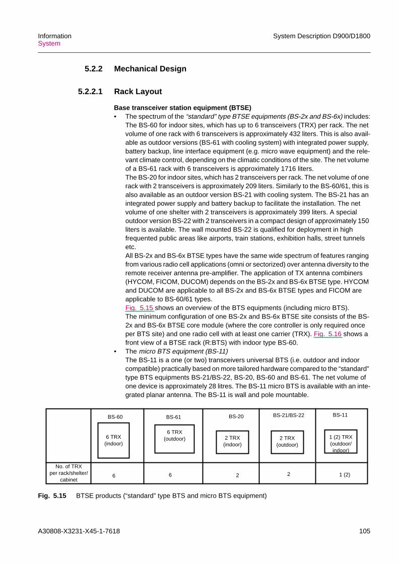
A30808-X3231-X45-1-7618 105
InformationSystem
System Description D900/D1800
5.2.2 Mechanical Design
5.2.2.1 Rack Layout
Base transceiver station equipment (BTSE)• The spectrum of the “standard” type BTSE equipments (BS-2x and BS-6x) includes:
The BS-60 for indoor sites, which has up to 6 transceivers (TRX) per rack. The netvolume of one rack with 6 transceivers is approximately 432 liters. This is also avail-able as outdoor versions (BS-61 with cooling system) with integrated power supply,battery backup, line interface equipment (e.g. micro wave equipment) and the rele-vant climate control, depending on the climatic conditions of the site. The net volumeof a BS-61 rack with 6 transceivers is approximately 1716 liters.The BS-20 for indoor sites, which has 2 transceivers per rack. The net volume of onerack with 2 transceivers is approximately 209 liters. Similarly to the BS-60/61, this isalso available as an outdoor version BS-21 with cooling system. The BS-21 has anintegrated power supply and battery backup to facilitate the installation. The netvolume of one shelter with 2 transceivers is approximately 399 liters. A specialoutdoor version BS-22 with 2 transceivers in a compact design of approximately 150liters is available. The wall mounted BS-22 is qualified for deployment in highfrequented public areas like airports, train stations, exhibition halls, street tunnelsetc.All BS-2x and BS-6x BTSE types have the same wide spectrum of features rangingfrom various radio cell applications (omni or sectorized) over antenna diversity to theremote receiver antenna pre-amplifier. The application of TX antenna combiners(HYCOM, FICOM, DUCOM) depends on the BS-2x and BS-6x BTSE type. HYCOMand DUCOM are applicable to all BS-2x and BS-6x BTSE types and FICOM areapplicable to BS-60/61 types.Fig. 5.15 shows an overview of the BTS equipments (including micro BTS).The minimum configuration of one BS-2x and BS-6x BTSE site consists of the BS-2x and BS-6x BTSE core module (where the core controller is only required onceper BTS site) and one radio cell with at least one carrier (TRX). Fig. 5.16 shows afront view of a BTSE rack (R:BTS) with indoor type BS-60.
• The micro BTS equipment (BS-11)The BS-11 is a one (or two) transceivers universal BTS (i.e. outdoor and indoorcompatible) practically based on more tailored hardware compared to the “standard”type BTS equipments BS-21/BS-22, BS-20, BS-60 and BS-61. The net volume ofone device is approximately 28 litres. The BS-11 micro BTS is available with an inte-grated planar antenna. The BS-11 is wall and pole mountable.
Fig. 5.15 BTSE products (“standard” type BTS and micro BTS equipment)
No. of TRXper rack/shelter/
cabinet
2 TRX(indoor)
BS-60
6 TRX(indoor)
6 TRX(outdoor) 2 TRX
(outdoor)
BS-61 BS-20 BS-21/BS-22
6 6 2 2
1 (2) TRX(outdoor/indoor)
BS-11
1 (2)

106 A30808-X3231-X45-1-7618
System Description D900/D1800 InformationSystem
Fig. 5.16 BTSE rack/cabinet configurations (type BS-60 for indoor installation andtype BS-11 with integrated antenna)
MBBCU2
SMUCB
RFTX2
RFRX2
SMURFTX1
Fuse panel
Antenna combining (ACOM)(HYCOM, RXMUCO) *)(FICOM, RXMUCO) *)
(DUCOM, RXAMCO) **)
RF part(TPU2, PA)
Ventilator
Power supply(DC)
Base band, Core(BBSIG, CCTRL, LI)
Ventilator + Air filter
Ventilator
F:PA
BS-6x BTSE Basic rack (R:BTS)
F:CORE
*) in case of separate TX and RX path**) in case of duplex equipment
RFRX1 MBBCU1
PA2
PA1
Filter
LNA
BS-11 BTSE cabinet

A30808-X3231-X45-1-7618 107
InformationSystem
System Description D900/D1800
Base station controller (BSC)
The BSC is contained in a subrack 724 mm high (with base module), 1448 mm high(with base + extension module), 300 mm deep and 600 mm wide. Thanks to its compactdesign occupying a space of less than 0.26 cubic meters and its low power dissipationthe BSC is operated without any fans or air condition. Therefore, the operator has thechoice of locating the BSC centrally in telecommunications rooms or remotely in ashelter or in a confined space. These BSC subracks are inserted into Siemens Informa-tion and Communication Networks (ICN) standard dimension racks (h x w x d = 2000 x600 x 300 mm) for adaption to the MSC/VLR site.
The BSC core module is always equipped with the necessary boards to provide the realtime processing performance for the maximum BSC configuration. BSC system capacitywith respect to the number of link interfaces (QTLP) or pre-processing boards for LAPDsignaling (PPLD) can be expanded. This can be done by expanding the base modulewith the expansion module and inserting additional boards into an already installedexpansion module.
This allows a very easy and gradual network growth to more complex and powerfulconfigurations without traffic interrupion. Fig. 5.17 shows a front view of a BSC rack(R:BSC) with basic module and expansion module.

108 A30808-X3231-X45-1-7618
System Description D900/D1800 InformationSystem
Fig. 5.17 BSC rack configuration
Transcoding and rate adaption unit (TRAU)
The TRAU is contained in a rack with max. 4 TRAU units (shelves) each processing 120traffic channels. The dimensions are height 2000 mm, depth 300 mm and width 600 mm.
Line interfaces(QTLP)
Signalling preprocessing(PPLD)
Signalling preprocessing(PPLD)
Line interfaces(QTLP)
Line interfaces, Signalling preprocessing(QTLP)
(PPLD/PPCC)
Core module(MPCC, SN16, IXLT, TDPC)
Part of ICN standarddimension rack
Fuse & Alarm panel
Subrack (R:BSC) in a ICN standard dimension rack
F:BSCEA
F:BSCB
F:BSCEB
**)
*)
*) Base module**)Expansion module
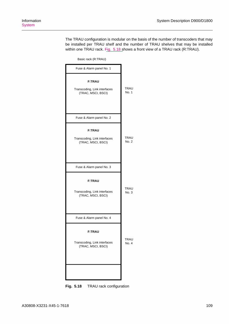
A30808-X3231-X45-1-7618 109
InformationSystem
System Description D900/D1800
The TRAU configuration is modular on the basis of the number of transcoders that maybe installed per TRAU shelf and the number of TRAU shelves that may be installedwithin one TRAU rack. Fig. 5.18 shows a front view of a TRAU rack (R:TRAU).
Fig. 5.18 TRAU rack configuration
Fuse & Alarm panel No. 2
Transcoding, Link interfaces(TRAC, MSCI, BSCI)
Fuse & Alarm panel No. 3
Transcoding, Link interfaces(TRAC, MSCI, BSCI)
Transcoding, Link interfaces(TRAC, MSCI, BSCI)
Fuse & Alarm panel No. 4
Fuse & Alarm panel No. 1
Transcoding, Link interfaces(TRAC, MSCI, BSCI)
F:TRAU
F:TRAU
F:TRAU
F:TRAU
Basic rack (R:TRAU)
TRAUNo. 1
TRAUNo. 2
TRAUNo. 3
TRAUNo. 4

110 A30808-X3231-X45-1-7618
System Description D900/D1800 InformationSystem
5.2.2.2 Floor Layout
Base station controller (BSC)
A BSC rack can be positioned anywhere in a room. Integration of the BSC rack into aoutdoor cabinet for outdoor installations is currently under investigation.
Base transceiver station equipment (BTSE) BS-2x and BS-6x
The BS-2x and BS-6x BTSE racks can be positioned anywhere in a room, wall or canbe pole mounted. Back-to-back installation is possible for BS-20 or BS-60. The outdoorcabinet BS-21 is a separate construction which containes the basic BS-20 rack and thecooling equipment. The outdoor cabinet BS-61 is a separate construction whichcontaines the basic BS-60 rack, the climate control equipment, the power supply andauxiliary equipment (e.g. microwave equipment).
Transcoding and rate adaption unit (TRAU)
The TRAU is always located at MSC sites.

A30808-X3231-X45-1-7618 111
InformationSystem
System Description D900/D1800
5.3 Software
5.3.1 BS-2x and BS-6x BTSE SoftwareFig. 5.19 shows the software architecture of the BS-2x and BS-6x BTSE.
Fig. 5.19 BS-2x and BS-6x BTSE software architecture
The BS-2x and BS-6x BTSE software comprises three main blocks:– operating system– radio and terrestrial channel handling (call processing)– operation and maintenance functions
All the software in the BS-2x and BS-6x BTSE (the basic bootstrap programs excepted)is down-loadable.
Operating system
The operating system provides the following services to the users:– task scheduling– task communication with mailboxes and events– time management– system calls to control the peripheral hardware– provides a unique, processor independent, interface to the user by an intermediate
layer, even though there is a different OS-kernel for each different processor type
Call processing (Radio and terrestrial channel handling)
Traffic channel handlingThis software is decentralized in the boards operating on a per-carrier-basis (the TPUs)and in boards handling the channel related tasks (the BBSIGs). The handling of the Umlayers is partly realised through special purpose hardware.• BBSIG
Down direction:– controls the traffic channel and unpacks the TRAU frames received from the bus2
Call processing software Operation and maintenance software
BS-2x and BS-6x BTSE Software
Abis-layer 2 LMT interfaceUm-layer 2
BTSE O.S.and
driver software
Operatingsystem (O.S.)
User software

112 A30808-X3231-X45-1-7618
System Description D900/D1800 InformationSystem
– codes traffic data (block and convolutional coding), interleaves, encrypts andmaps them on bursts with a format usable by the Um-interface
– concatenates additional information for power control with the traffic dataaddressed to a TPU2. This is transmitted through the bus1, which is used as aswitch between the BBSIGs and the TPU2s
Uplink direction:– performs demapping, decryption, deinterleaving, convolutional and block
decoding. The BBSIG packs at last the traffic data in the TRAU frames• TPU
Downlink direction:– power control information is passed to the PA (static power control in 6 steps and
dynamic power control according to GSM standard)– the midamble is inserted to the traffic data and passed to the analogue processing
Uplink direction:– the serial data are at first filtered and equalised in the TRXD, then sent through
the bus1 to the BBSIG logically connected to the terrestrial channel according tothe frequency hopping scheme
Signaling channel handling• CCTRL
Downlink direction:– the signaling channels on the Abis interface are routed along the bus2 to the
CCTRL, which handles the LAPD protocol– a message dispatcher passes Abis layer 2 management and O&M messages to
the main processor in the CCTRL– it also forwards call control messages to the BBSIGs
Uplink direction:– in the uplink direction the dispatcher manages the access of the different entities
to the LAPD channels• BBSIG
– the BBSIG software realizes the interworking between the RR sublayer of theUm-interface and the BTSM sublayer of the Abis-interface and also maps thedifferent Um signaling channel types onto the Abis signaling channels. TheBBSIG handles the LAPDm protocol and the interface to the Um layer 1 functions
Operation and maintenance functions
O&M functions are:– software management including downloading– configuration management– fault treatment management– test management– performance management
The O&M functions are hierarchically organised in the BS-2x and BS-6x BTSE. TheCCTRL software controls all O&M functions in the BS-2x and BS-6x BTSE. The O&Minformation is received and transmitted via the Abis-interface. Each O&M function in theCCTRL has a corresponding local function in each main processor connected to thebus1. There local functions coordinate the same function in the subordinate processorsconnected to it (on the same board or in a peripheral board).

A30808-X3231-X45-1-7618 113
InformationSystem
System Description D900/D1800
5.3.2 BS-11 BTSE SoftwareFig. 5.20 shows the BS-11 BTSE software architecture. Each software module pointsto the cards in which is executed.
Fig. 5.20 BS-11 BTSE software architecture
The BS-11 software comprises the following blocks:– micro BTS operating system– site manager (SM) software– digital signalling processor(DSP) software– TRX O&M– level 3 (L 3) software– level 1 (L 1) software
Operating system
The operating system is a proprietary system, specially designed for telephonic applica-tions. The main functions are process scheduling in a event-driven mode, event debug-ging and tracing and process timing.
Site manager (SM) software
The site manager software is subdivided in two main areas: interface module and SMO&M module and is executed by two processors in the SMU, each one dedicated to aMBBCU. The interface module manages the Abis interface to/from BSC, the LAPDprotocol for example. The O&M module provides the alarm handling, the configurationhandling and the software handling for example.
DSP software
The DSP software is subdivided in 6 modules distributed on 16 DSPs (1 on RFTX, 1 onRFRX and 14 on the MBBCU) for each TRX. At each module is associated a function-ality. The functions of DSP software are: RF handling (RX and TX), channelcoding/decoding, remote transcoder control, GMSK modulation/demodulation andencryption algorithm management.
TRX O&M software
The TRX O&M software on each MBBCU performs the same software. The functionsprovided by this software module are related to TRX management, namely alarmhandling, configuration handling and status handling.
Site managersoftware
BS-11 BTSE Software
SMU
DSPsoftware
TRX O&Msoftware
Level 3software
Level 1software
RFRX RFTX MBBCU
HW

114 A30808-X3231-X45-1-7618
System Description D900/D1800 InformationSystem
Level 3 (L 3) software
The L 3 software on each MBBCU is loaded with the same software. The L 3 softwareis subdivided in two main areas: Application module and O&M module. The applicationsmodule provides CCCH signalling, TRX signalling, hand-over management, powercontrol management, power control management and SM interfacing.
Level 1 (L 1) software
The L1 software on each MBBCU performs the same software. The L 3 software issubdivided in two main areas: Application module and interface module. The applicationmodule provides LAPDm protocol, radio physical layer handling and RX automatic gaincontrol for example.
5.3.3 BSC-SoftwareFig. 5.21 shows the BSC software architecture.
Fig. 5.21 BSC software architecture
The BSC software can be subdivided into 5 main blocks:– operating system– MPCC software– TDPC software– PPXX software– IXLT software
MPCC Software TDPC Software TDPC Software TDPC Software
Status administration& audit
System maintenance
Databaseadministration
Switching networkcontroller
BSC Software
Status administration& audit
System maintenance
Databaseadministration
Layer 3 applicationsoftware
CCS7 level 2 handling
LAPD handling
Interface to OMC-B(X.25)
Interface to LMT (V.11)
BSC O.S.
O.S. kernel
Input/output handling
InitializationCentral processors
Peripheral processors
Operatingsystem (O.S.)Performance
managementPerformancemanagement

A30808-X3231-X45-1-7618 115
InformationSystem
System Description D900/D1800
Operating system
The OS kernel (real time executive plus, RTE+) manages the following resources:– CPU time (real time)– system memory (dynamic allocation of memory areas)– task communication and synchronization devices (mailbox, event, semaphore)– system timing
RTE+ also includes special functions related to:• support the finite state machine model, which accounts for programming the appli-
cation software using the SDL methodology• CPU performance monitoring the hardware configuration management system time
and date supervision• input output handling, which includes:
– OS inter processor communication functions; the communication is supported inthe hardware by the provision of a dual ported RAM
– MML interface (OMC & LMT), supporting:- OS initialization- software management; this element is responsible for protected memorymanagement
Board functionality• MPCC software
It is divided into the following packages:– status administration & audit; it controls the operational status of all hardware
devices in the system by processing either internally or externally initiated statustransition requests. Alarm reporting functions are also implemented in thispackage
– system maintenance; it provides hardware recovery functions (fault detection,fault isolation and service restoring) and hardware diagnostic procedures. TheMPCC is the master processor in driving all the recovery and diagnosticprocesses for all system hardware
– database administration; it provides procedures for initializing the system config-uration data and the operational parameters driving the system features
– switching network controller; it sets up the digital connection between the A andthe Abis-interfaces, as directed by the call-processing software in the TDPCprocessor
– performance management; its main function is to provide statistical reports of thesystem behaviour
• TDPC softwareEach software package resident in the MPCC, the switching network controllerexcepted, has a counterpart in the TDPC which acts as ”slave” to the MPCC resident”master”.For example, a database update process is driven by the database administrationsoftware in the MPCC, which may activate a ”slave” process in the TDPC to updatethe TDPC resident portion of the database affected by the change.
This means that the TDPC software contains the following packages:– status administration & audit– system maintenance– database administration– performance management

116 A30808-X3231-X45-1-7618
System Description D900/D1800 InformationSystem
In addition, there is the following package: OSI layer 3 application software,providing:– call processing capabilities; they include all the functions related to call handling
procedures, radio/ terrestrial resource management and BSC call management– functions related to layer 3 (message transfer part (MTP), and signaling connec-
tion control part (SCCP)) of the CCS7– functions related to message reception and transmission to/from Abis-interface
and A interface• PPXX software
The peripheral processors PPLD and PPCC realize the level 2 of the protocol stackstoward the BTSE and TRAU (LAPD) and the MSC (ITU-T CCS7) respectively.
• IXLT softwareThe IXLT processor realizes the OSI stack toward the operation and maintenancecenter for BSS (OMC-B). It also implements the interface to the local maintenanceterminal (LMT).
5.3.4 TRAU-SoftwareFig. 5.22 shows the TRAU software architecture.
Fig. 5.22 TRAU software architecture
For all processors the software is loadable from the BSC.
BSCI Software MSCI Software TRAC Software
Status administra-tion & audit
Systemmaintenance
Databaseadministration
Transcoder matrixmanagement
TRAU Software
LAPD Handling Transcoding & rateadaption
Diagnostic
TRAU O.S.
O.S. kernel
Input/output
Initialization
Performance datacollection
TRAU controller
HDLC Handling
Diagnostic
Peripheral processors
Operatingsystem (O.S.)

A30808-X3231-X45-1-7618 117
InformationSystem
System Description D900/D1800
The main blocks of the TRAU software are:– operating system– BSCI software– MSCI software– TRAC software
Operating system
The OS kernel depends on the processor used.
In detail, the different OS kernels are:– the RTE+ (real time executive plus) on the BSCI;
it is the same OS kernel used in the BSC– the RTE (real time executive) on the MSCI and on the TRAC;
it is a proprietary operating system specifically designed to work in a very hard realtime environment. The RTE basic features are: multitasking, task synchronization,timeout handling, message exchange, memory resource management
– a simplified scheduler on the TRAC;it is specifically designed to support, in an optimized way, the functionalities of thisprocessor
Board functionalities• BSCI software
– houses the central controlling function of the TRAU, which is responsible for- hardware configuration- fault management- test management- performance management collection- database administration- transcoder matrix management
– interface function from TRAC towards the BSC• MSCI software
The main blocks of the MSCI software are:– LAPD handling;
provides a protocol handler for the O&M communication link between BSC andTRAU; the application part is on the BSCI
– HDLC handling;provides a protocol handler for the BSCI-MSCI interface; the application part is onthe BSCI
– diagnostic;provides internal diagnostic processes that will run under BSCI processor control
• TRAC software
It provides the following functions:– transcoding and rate adaption– discontinuous transmission (DTX)/voice activity detection (VAD)– drop-insert operation upon command, independent from that of the other cards,
either on the BSC line or on the MSC lines– the BSC can configure in any way and without restrictions the correspondence
between the channels in the BSC line and the channels in the MSC lines– diagnostic;
provides internal diganostic processes that will run under BSCI processor control

118 A30808-X3231-X45-1-7618
System Description D900/D1800 InformationSystem
5.3.5 Software ManagementIn order to fulfill the specific GSM standards about network management procedures theD900/D1800 BSS has a structured software management. The software managementincludes a strategy about software recovery which is a kind of software fault defenceaction. The software related recovery actions consists of– initialization– downloading or reloading procedures
Initialization
An initialization procedure has the possibility to affect only the involved data areas andis distinguished by– system restart (bring up initialization), with reload– full initialization– lower level initialization• System restart
A system restart is the initialization that occurs after a reload.• Full initialization
The full initialization is the restart (without reloading) of the affected networkelement. It can be manually activated (from LMT and/or OMC-B) but can also beactivated automatically by the system defence action for specific errors that haveoccured.
• Lower level initializationA lower level initialization is according to a specific software task. It can be manuallyactivated but can also be activated automatically by the system defence action forspecific errors.
Downloading, loading/reloading• Downloading
Downloading is the procedure of transfering executable files (load image files) fromOMC-B/LMT to the BSC hard disks and subsequent to the other BSS networkelements. In the OMC-B/LMT there is an installation program that moves the soft-ware packages being released in three directories. A directory ” backup” holds acopy of the current running software version for all the BSS network elements,another directory ”fallback” holds a reliable software version for all BSS networkelements and a third directory ”new” holds the new software version in case ofupdate/upgrade.
• Loading/reloadingThe loading/reloading procedure affects a data and software image transfer whichdescribes the actual phase of putting code onto processors memory. The loadingprocedure can be divided into: system bring up and software version changes.A system bring up is intended as the (re-)starting of the whole BSS after a powerdown/power up sequence.A software version change is the loading of a new software version while the BSS isrunning and keeping at minimum the loss of service.
Software image
A software image consists of executable code and/or of data areas. This data is a kindof semipermanent data which can be modified from the operator during the lifetime ofthe system. Transient data could not be recovered via downloading or reload proce-dures.

A30808-X3231-X45-1-7618 119
InformationSystem
System Description D900/D1800
System upgrades
System upgrades, e.g. for the introduction of new features follows the GSM standardswhich includes– loading of the new software onto the OMC-B– downloading the BSS software– amending the BSS database– activate the new software and parameter changes– bringing the BSS back into service
All these activities are operator invoked actions which are provided by the BSS.

120 A30808-X3231-X45-1-7618
System Description D900/D1800 InformationSystem
6 O&M Subsystem (OMS)The D900/D1800 network provides the features of a GSM system; it consists of:– a telecommunication system composed of the base station system (BSS) and the
switching subsystem (SSS)– a telecommunication management network (TMN), represented by the O&M
subsystem (OMS)
The open concept of the TMN permits flexible adaptation of the OMS to the needs of thenetwork operators. The D900/D1800 OMS supports centralized and decentralized (i.e.local) operation and maintenance of the nodes of the PLMN.
Protection against faults has been achieved to a great extent by means of built-inmeasures. If simple faults occur they are eliminated by automatic recovery proceduresand the PLMN operator does not need to intervene. In the case of more serious faults,information is supplied to enable the operator to recognize and remove the fault source.In severe cases the affected network element or network node is taken out of operationand the operator is warned. Whenever possible, the system adapts its configuration andcontinues operation.
6.1 System ArchitectureThe OMS is realized in operation and maintenance centers (OMCs), which consists ofan OMC-B for administration of BSS network elements and an OMC-S for administrationof SSS network elements within the PLMN. The operation and maintenance for SSS andBSS are independent of each other. The OMC-B and OMC-S can be combined in thesame location. The OMC can also be connected with network components of an oper-ations system (OS) via a PSDN or LAN with TCP/IP protocol (Fig. 6.1). Components ofan OS are, for example, the personalization center for SIM (PCS), security managementcenter (SMC) or data post processing system (DPPS).
Fig. 6.1 OMS network architecture
PSDN/LAN
D900/D1800 SSS/BSS
SSS networkelements
OMC-S
BSS networkelements
OS
D900/D1800 OMS
PSDN
OMC-B

A30808-X3231-X45-1-7618 121
InformationSystem
System Description D900/D1800
Logically, an OMC-S is linked to one or more SSS network nodes, and an OMC-B islinked to one or more BSCs, even if the BSCs are connected to different MSCs.
National OMC
The national OMC provides a means to centralize O&M functions. This is particularlyuseful for the BSS side of O&M providing a simple means to bring together all informa-tion from regional, usually geographically dispersed OMC-Bs. This overlay operation isshown in the hierarchical structure of Fig. 6.2. The national OMCs can be assigned tothe OS area and correspond to the OS components of the network management center(NMC) type. The national OMCs allow what is known as a night/weekend service config-uration of all the OMC activities. To connect a regional OMC and a national OMC, X.25connections (PSDN) with an OSI stack and object-oriented information model of theBSS are used.
The national OMC has the same functions as the regional OMCs, including e.g.:– status management– configuration management– fault management– performance management
Additional functions such as night service configuration, monitoring of trunk lines to theregional OMCs are also included.
Fig. 6.2 National OMC for OMC-B
PSDN (X.25)
PSDN (X.25)
National OMC
RegionalOMC(-B)
RegionalOMC(-B)
SSS networkelement
BSS networkelement
SSS networkelement
BSS networkelement
Night service configuration
OMS/OS
BSS/SSS

122 A30808-X3231-X45-1-7618
System Description D900/D1800 InformationSystem
6.1.1 Network Components
6.1.1.1 OMC for the SSS and BSSThe structure of the OMC-S and OMC-B is shown in Fig. 6.3.
Fig. 6.3 OMC for the SSS and BSS
The operation and maintenance terminals (OMT) and the O&M processors (OMPs) areconnected to local area networks (LANs) in the OMC. The OMP-S has access to thenetwork nodes of the SSS and the OMP-B has access to the network nodes of the BSS(the BSCs) via the packet-switched data network (PSDN). As an option the access ofthe OMC-B to network nodes of the BSS can be realized via MSC PCM30 links (nailed-up connections, NUC). All connections to the PSDN are ITU-T Standard X.25 connec-tions.
6.1.2 Interfaces of the OMSThere are three interfaces from the OMC-S to the SSS or BSS (see Fig. 6.3):– the interface between the OMP-S and the SSS network nodes (MSC/VLR, HLR/AC,
EIR) via an X.25 interface– the O-interface:
interface between the OMP-B and the base station control (BSC) via an X.25 inter-face. Optionally the interface between the OMP-B and BSC can be realized byPCM30 nailed-up connections via MSC (see Section 5.1.2).
– the interface between the OMP and an OS center (PCS, SMC, NMC etc.) via a Q.3-interface. In the case of OMP-S to OS centers optional a TCP/IP LAN protocol ispossible.
LANLAN
Q.3
X.25D900/D1800 SSS/BSS
MSC/VLR
OMT
OMP-S
D900/D1800 OMS
HLR/AC TRAU/BSC/BTSE
OS (PCS, SMC, NMC...)
OMT OMT OMT
OMP-B
LMTBCTBCT

A30808-X3231-X45-1-7618 123
InformationSystem
System Description D900/D1800
Additionally there are two O&M interfaces in the SSS and BSS network nodes:– the interface between the local O&M terminal (BCT) and the SSS network nodes
(MSC/VLR, HLR/AC, EIR)– the T-interface:
direct interface between the LMT and the BSC, TRAU and BTS (see Section 5.1.2).
6.2 Hardware Architecture
6.2.1 Hardware of the OMC-S
OMP-S
A commercial computer (SUN Sparc/Enterprise) with all the security measures that cannormally be provided is used as the OMP-S. A number of OMP-Ss can also be used inan OMC-S in order to operate the connected SSS network elements or to guaranteesystem redundancy. Each OMP-S can be configured for dedicated functionalities, e.g.as file server, mediation server or performance management (PM) server.Mirrored disks are used to hold identical data on two magnetic disks. This makes itpossible to provide a failsafe database in a client-server system (needed with softwareupgrade for example). A subfunction here is OMP-S switchover on failure of an OMP-Sto allow access to important data.
OMT
There are various types of operation a maintenance terminal available. They differ in thehardware used and the type of connection to the OMP-S:
The types of operation and maintenance terminal used are as follows:– workstation (OMT)
A workstation is a commercially-available computer (SUN Sparc) with a colorscreen.
– X-terminal (OMTX)An X-terminal is a color SUN Sparc X-terminal. It is connected to the LAN.An OMP-S is used as a server.
– TSC terminalThe TSC terminal is available as an option. It gives the manufacturer remote accessfor maintenance purposes in emergency situations. For the network provider remotediagnosis by the manufacturer can save a great deal of time and money.
The following remote access OMTs can be operated:– OMTR: Remote OMT by dialing in via the PSDN(X.25) or via the ISDN/PSTN, or via
the GSM radio interface itself.– TSC terminal: Remote OMT via the PSDN(X.25), especially for access by the tech-
nical service center (TSC) of the PLMN manufacturer to the PLMN networkelements.This allows PLMN manufacturing specialists to participate in the error defi-nition process in emergency situations.

124 A30808-X3231-X45-1-7618
System Description D900/D1800 InformationSystem
Local O&M terminals in the SSS network nodes:
BCT
Personal computers are used as local O&M terminals (BCT) for installation purposesand for local operation and maintenance work. The BCT are equipped with Windows NToperating system and CD-ROM drives. The operating documentation (including thecurrent description and the various manuals for operation and maintenance) is availableon paper and/or CD-ROM.
6.2.2 Hardware of the OMC-B
OMP-B
The OMP-B used is a commercially available computer (SUN Sparc/Enterprise). TheOMP-B can be optionally duplicated with hot standby redundancy.
OMT
Following different types of OMTs are available:– SUN graphical workstations– X-terminals (SUN Sparc classic X)
The standard configuration has up to 8 graphical workstations or up to 4 graphical work-stations and 4 X-terminals connected to OMP-B (to both OMP-Bs in case of redun-dancy) locally via LAN. Maximum configuration is 8 OMT assemblies.
The following remote access OMTs can be operated:– OMTR: Remote OMT by dialing in via the PSDN(X.25) or via the ISDN/PSTN.
Additionally an interworking is possible of the OMT of a neighboring OMC-LAN intoa separate OMC-LAN, or by a remote login of a OMT of an OS network componentto the OMP-B via a X.11-LAN connection,
– TSC terminal: Remote OMT via the PSDN(X.25), especially for access by the tech-nical service center (TSC) of the PLMN manufacturer to the PLMN networkelements.This allows PLMN manufacturing specialists to participate in the error defi-nition process in emergency situations.
LMT
The same LMT hardware with its T and Tµ interfaces is used for the BSS entities (BSC,BTSE, micro BTS included, and TRAU). It is recommended the use of portable PC withIntel 80386 (or higher) CPU, AT bus, MS-DOS 5.0 (or higher) and Windows 3.1 (orhigher). Local maintenance terminals (LMT) are available for operation and mainte-nance work at the BSS network element (BTSE, BSC, TRAU) site.• BS-2x and BS-6x LMT
The proprietary interface T (X.21/V.11) is used for direct access to the BS-2x andBS-6x BTSE, BSC and TRAU.The LMT has the capability to identify the mode itself by communicating with theconnected BSS network element (BSC mode, BTSE mode, TRAU mode). It is alsopossible to open a LMT remote session in the BSC from an LMT connected to anyunderlying BS-2x and BS-6x BTSE or TRAU and configure the BSC and the func-tional objects of all other BS-2x and BS-6x BTSEs or TRAUs within this BSC area.The LMT is used for first installation of SBS software and configuration, faultrepairing and removing.

A30808-X3231-X45-1-7618 125
InformationSystem
System Description D900/D1800
• BS-11 LMTThe interface Tµ (RS232/V.24) is used for direct access to the BS-11 (micro BTS).Two different SW applications are used (not at the same time), both residing on theLMT PC mass storage. However the former application (suited for the maintenanceof the BSC, TRAU, BS-2x and BS-6x BTSE via the T interface) can also be used foraccessing the BS-11 in remote mode from the BSC.
6.3 Software Architecture
6.3.1 Software Architecture of the OMC-SThe software supplied for the components of the OMC-S consists of a software platform,basic system and application software (Fig. 6.4). This application software is adaptedto the needs of a telecommunication management network (TMN). It consists ofprocesses (in the UNIX sense) for the various requirements of the operation and main-tenance applications, e.g. operator inputs or messages from the network nodes of SSS.
Fig. 6.4 Components of OMS-S software
Software platform
The software platform consists of commercially available software systems complyingwith international standards. The main components are:– operating system Solaris®/UNIX®, System V– network file system– database management system (Informix, or for some application software units the
commercial database product ORACLE®)– graphics program WINGZ– window manager OSF-Motif– window system X/Window
Operation and maintenanceapplications
X/Window(OSF/Motif)
Databasemanagement
system(e.g. Informix)
Utilities
UNIX® V
Communication software
FTAM CMISE
X.25 TCP/IP
Basic system

126 A30808-X3231-X45-1-7618
System Description D900/D1800 InformationSystem
– communications software:for WAN communication: CMISE, FTAM in accordance with OSI standards (i.e.based on X.25); for LAN communication: TCP/IP
Basic system
The basic system includes the following parts:– installation– recovery– central functions which allow general access to utilities– LAN and WAN communication– file transfer functions to the network elements of the SSS or to the OS
Application software
The application software is divided into the following groups:– basic applications– applications for the OMS– applications for the SSS– mediation functions (MF)• Basic applications
The basic applications include:– security management (access protection mechanisms)– graphical user interface (GUI)– online help system– time synchronisation in OMC-S with the SSS networks elements– command logging– computer and database structure– usage of a more comfortable windows manager
(common desktop environment (CDE))– OMC-S process supervision– printer interfaces– OMC management/configuration– connection possibilities of OMT
• OMS applications
OMS applications include:– configuration management (CM)– fault management (FM)– OMS status display (OSD)
• SSS applications
SSS applications include:– MML management
containing among other things the input of extended MML (EMML) or basic MML(BMML), which is used for operation of the SSS network nodes and the automaticoperator (ATOP), which supports the recording of input commands in a preparedfile
– fault management (FM)containing among other things the graphic system status display (SSD) is used tomonitor the SSS network nodes. Additionally the SSD can also be used to controlthe Siemens BSS network elements.

A30808-X3231-X45-1-7618 127
InformationSystem
System Description D900/D1800
– performance management (PM)Analysis and graphical display of the traffic measurement data of the SSS with anindependent software package (SPOTS).
– SSS manual on OMT– graphical user interface (GUI)
• Mediation functions (MF)The mediation functions (MF) convert the Q.3 interface (TMN) between OS andOMC-S into the Qx interface between OMC-S and the network elements. Due to themediation functions, the OS has access to the necessary data of the networkelements or network nodes of the SSS.
There are mediation functions for the following, for example:– subscriber administration
(dialog of subscriber data between the SSS network elements HLR/AC and theOS with the dialog service CMISE)
– fault management(dialog of alarm messages between the SSS network elements and the OS withthe dialog service CMISE)
– control and administration of data for call charging(transfer of call charge data between MSC and the OS with the file transfermethod FTAM)
– transfer of S-tickets for juridical interception(between MSC and the OS with dialog service CMISE)
6.3.2 Software Architecture of the OMC-BThe OMC-B software architecture has been designed according to the standards andrecommendations established by the OSF (Open Software Foundation) in order that thesoftware will be as hardware platform independent as possible.
The software supplied for the components of the OMC-B has nearly the same structureas the software supplied for OMC-S (see also Fig. 6.4). The structure of the softwareplatform (e.g. operating system Solaris®/UNIX®, database product ORACLE®) andbasis system is the same in principle. Differencies are given in the application softwarelike shown in the following.
Application software
The application software is divided into the following groups:– basic applications– applications for the OMS– applications for the BSS– mediation functions (MF)• Basic applications
The basic applications include:– security management (access protection mechanisms)– graphical user interface– online help system– time synchronisation in OMC-B with the SSS networks elements– command logging– computer and database structure– usage of a more comfortable windows manager
(common desktop environment (CDE))

128 A30808-X3231-X45-1-7618
System Description D900/D1800 InformationSystem
– printer interfaces– OMC management/configuration– connection possibilities of OMT
• OMS applications
OMS applications include:– configuration management (CM)– fault management (FM)
• BSS applications
BSS applications include– configuration management (CM)
which contains the management of the network resources (e.g. radio channels)– fault management (FM)
which contains the measures necessary to detect and remove faults– performance management (PM)
which contains the supervision and evaluation of the traffic load and the perfor-mance of the BSS network
– software management (SWM)which contains the management and control of the software and the databasesof the BSS
– BSS manual on OMT– graphical user interface (GUI)The basis of the OMC-B application is a hierarchiy of geographical maps, functionalpanels and rack layouts on which current status of all ”managed objects” isdisplayed. Further this gives the possibility to step in every fault management,configuration management or software management application with the most userguidance.
• Mediation functions (MF)The mediation functions (MF) convert the Q.3 interface (TMN) between OS networkcomponents (e.g. a network management center (NMC)) and OMC-B into the Qxinterface between OMC-B and the BSS network elements. Due to the mediationfunctions, the OS has access to the necessary data of the network elements ornetwork nodes of the BSS.There is a mediation function for fault management (dialog of alarm messagesbetween the BSS network elements and the OS), for example.

A30808-X3231-X45-1-7618 129
InformationSystem
System Description D900/D1800
7 FunctionsThe services of the PLMN or CSC bases on the network functions. They cover– basic functions of call handling– mobile-specific functions of call handling
7.1 Basic Functions of Call Handling
Call types• GSM subscriber
The basic call handling functions establish calls between a GSM subscriber (GSMmobile subscriber and on CSC GSM-RITL subscriber) and another subscriber in aPSTN, an ISDN, a PSDN or a GSM subscriber in the same or another PLMN.
The following call types are possible:– mobile originated call (MOC)– mobile terminated call (MTC)
A special case based on the two basic call types is also possible:– mobile to mobile call (MMC)
• Fixed network subscriber (wired ISDN/analog subscriber) at the CSCFor fi xed network subscriber at the CSC subscriber only the conventional callhandling functions for fixed network subscribers are needed, i.e. no mobile-specificfunctions.
• IN/CAMEL call handlingAll kinds of subscribers of a PLMN or CSC are provided with call handling functionsfor various IN/CAMEL applications.
Number portability for fixed and GSM subscribers
The feature “number portability” allows subscribers to change the network withoutchanging their number and local area code (LAC) or national destination code (NDC)(for GSM subscribers this means without changing their MSISDN. The GSM subscribersIMSI will be changed). This feature supports porting of fixed network subscribers (PABXsubscribers included) and GSM subscribers. Porting-in means GSM subscribers andfixed network subscribers can be ported from a foreign network to the own network bykeeping their old number. Porting-out means GSM subscribers and fixed subscriberscan be ported-out from own network by keeping their old number.
By introducing the number portability functionality in the PLMN, new subscribers fromother PLMN as well as from fixed networks can be attracted. Especially the ability ofporting subscribers from fixed networks to PLMN by keeping the subscribers number isa possibility to attract a lot of new mobile subscribers to the PLMN.
Full-rate and half-rate channel connections
In a GSM Phase-1 PLMN only full-rate channel connections are supported, i.e. theuseful data is transmitted on the GSM radio interface at a speed of 22.8 kbit/s. GSMPhase 2/2+ will support half-rate channel connections (transmission speed of 11.4kbit/s).
The D900/D1800 SSS and BSS supports the half-rate channels for voice services. Fordata services, half-rate channels are supported by the BSS but not by the SSS.If the MSC is used as a gateway MSC to a satellite network (GSC), the MSC supportsboth full-rate and half-rate channel connections for data services.

130 A30808-X3231-X45-1-7618
System Description D900/D1800 InformationSystem
The D900/D1800-BSS permits “dual-rate” operation, i.e. full-rate (FR) and half-rate (HR)operation at the same time. If a full rate channel operation is upgraded to full rate andhalf rate channel operation, changes to the hardware must be made in the BSC andTRAU and changes to the software in the BTS, BSC and TRAU. In particular, the half-rate transcoders which operate at a user data rate of 6.5 kbit/s (compared with 13 kbit/sfor full-rate operation) have to be upgraded in the TRAU.
Enhanced full-rate channel connections
The D900/D1800 SSS and BSS provide the necessary signaling for using GSM Phase2+ compatible mobile stations with enhanced speech quality Codec versions, whichhave a better connection quality compared to that in fixed networks. The PLMN operatorcan activate/deactivate this support (enhanced full-rate channel, EFR) in the PLMN andso control the use of new speech quality Codec version.
Handling of GSM subscriber telecommunications services
The bearer services are used only for pure data services. They provide the necessaryfundamentals for the operation of these pure data services. The teleservices define bothvoice and also data services. Supplementary services expand the functionality of thebasic telecommunications services (bearer services and/or teleservices).
The GSM telecommunications services that are possible in the D900/D1800 are listedin Section 3.
GSM Phase 2+/Phase 2/Phase 1 (Fallback)
The D900/D1800 offers the services supplied in GSM Phase 2 or GSM Phase 2+ andGSM Phase 1. In the case of GSM Phase 2/2+ this means that it supports typical Phase2/2+ telecommunication services such as multi-party service (MPTY) or closed usergroup (CUG). The GSM Phase 2/2+ signaling is supported by the CCS7 user partsBSSAP, MAP and TCAP. The MSC offers a ”fallback” from Phase 2/2+ handling tohandling in accordance with the Phase 2 features.
User informations
Audible tones, announcements and displays inform the calling subscriber in theD900/D1800 network (GSM subscriber or wired ISDN/analog subscriber) and thesubscriber in the ISDN/PSTN about the status of the call setup.
Generation of call data records
Detailed call data is generated for the GSM mobile subscriber or for the GSM-RITLsubscriber or wired ISDN/analog subscriber during every call transaction. The call datarecordings can be used for charge registration, network management and supervisionpurposes. After the call data recordings have been generated they can be provided withcustomer-specific data record formatting.
For charge data recording there are two basic procedures available in the MSC or theCSC:• Automatic charge data recording
The call charges for all subscriber types in the D900/D1800 can be recorded byautomatic charge data recording. An exception to this rule are subscribers withprepaid charges (PPSC subscriber/debit subscriber).Automatic charge data recording generates at least one regular charge data recordfor every successful call or the use of a service.

A30808-X3231-X45-1-7618 131
InformationSystem
System Description D900/D1800
Depending on the kind of subscriber of the D900/D1800, two different kinds of calldata records are generated.– mobile call record (MCR) data records for GSM subscriber (mobile and RITL)– automatic message accounting (AMA) data records for fixed network subscribers
at CSC (wired subscribers)The charge data recording by the D900/D1800 IN network node M-SSP is usuallyalso performed by automatic charge data recording. More about this is describedbelow under IN charge data.
• Pulse meteringFor the ISDN/analog subscribers at the CSC, meter pulses can be created for eachcall or for activating/using supplementary services.
In the CSC the pulse metering methods employed are as follows:– SPM (single pulse metering)– MPM (multiple pulse metering)– PPM (periodic pulse metering)
• IN charge dataThe introduction of highly-developed intelligent network (IN) services in a GSMPLMN requires an expansion to the previous D900/D1800 charging concept. Thebasic idea is for both parties involved, i.e. the IN service user (calling line) and theservice subscriber (called line) to share the charges accrued in a variety of very flex-ible ways. The question of “Who pays for what ?” must always be answered in aservice-independent and service-subscriber-specific arrangement.
There are basically two ways of charging for IN calls:– charge recording via the SCP/SMP– charge recording based on the M-SSP
• Customer-specific data record formattingIf necessary the regular charge data (MCR/AMA or pulse metering data) can beconverted into a customer-specific data record format before being transferred to aparticular data post-processing system (DPPS). In the data post-processing systemthe data records are handled according to their use (e.g. for calculating the totalcharges to the GSM subscriber served or to monitor the location of the GSMsubscriber).
• Hot operationThe term hot operation covers all cases in which MCR/AMA data records are addi-tionally generated and/or formatted and transmitted to a dedicated processingcenter via the packet switched public data network (PSPDN) while a call is still inprogress or immediately after it has ended. There are the following two applicationsfor this:
The four applications involved here are as follows:– hot billing data record recording– emergency call trace data record recording– IMSI trace data record recording– interception data record recording
Distance related charging
This function - distance related charging, DRC - records charges directly from the calls,especially from mobile-to-mobile calls (MMC), dependent on the distance between Asubscriber and B-subscriber. In this way a call for the GSM mobile subscriber is cheaperif the call partners are nearer to each other (e.g. within a city with one city tariff)compared to a connection from opposite ends of a country. Even the combination of

132 A30808-X3231-X45-1-7618
System Description D900/D1800 InformationSystem
distance related to e.g. calender/time of day is conceivable for a tariff. local informationabout the call partners is provided for data post-processing.
Interadministration procedures for billing/revenue accounting (IACHASTA andIARA)
The new IACHASTA (Interadministration charging and statistics) function is a flexibleprocedure for charge accounting between different PLMNs and permanent networkswithin a country, or between different countries.
It is also possible to use the features of the old function IARA (Interadministrationrevenue accounting), but not simultaneously with IACHASTA. The IACHASTA proce-dure is a further development of the IARA procedure. The PLMN operator can eitherchoose the new IACHASTA procedure or the old IARA.
The principle of both procedures is:– suitable metering procedures for recording the connection traffic– suitable output formats of the metered data
Both procedures can either be used in the GMSC or in the gateway switching center ofthe PSTN/ISDN.
7.2 Enhanced Functions of Call Routing, Charging and UserInformation
Flexible routing of calls in the SSS (SDDPFC)
The standard procedure provided to handle "normal" call setups assumes that, for aterminating call a digit translation will be affected first. After this a particular destinationwill be reached, for example via a specified destination and route, or a defined proce-dure will be triggered by means of a particular traffic type.
In the case of calls involving GSM subscribers (including GSM-RITL subscribers) andwhere the defined features are available the call data can be modified prior to the digittranslation. This produces one of the following results:– modification of the entry data for digit translation and routing control, followed by the
start of the normal procedure (i.e. digit translation, etc.)– modification of the data for call charge registration– bypassing digit translation by means of direct transition to an IN service– control (i.e. application or prohibition) of specific features
A consequence of this flexible routing of calls in the SSS (subscriber-dependent digitprocessing and feature control, SDDPFC) is therefore that specifications derived fromother entries in the database of SSS network nodes can be modified. In other words, itcan lead to partly or completely different behavior than would have been expected undernormal circumstances. For precisely this reason, this powerful and highly useful featureshould be used with greatest of care!
A-number dependent routing, charging and barring in the SSS
These SSS functions expand the flexible routing of calls in the SSS (subscriber depen-dent digit processing and feature control, SDDPFC) with a feature control (FC) element.
It consists of the part functions:– A-directory number dependent routing– A-directory number charging (zoning)– “black list” for barring connections

A30808-X3231-X45-1-7618 133
InformationSystem
System Description D900/D1800
Approximately 20000 different directory numbers can be saved in the database inrelazion to this function. The operator can administrate individual A-directory numberswhich begin with the same digit combination. The input in the database of e.g. 1234allows the same routing/call charging/blocking of all A-directory numbers which beginwith 1234.
Possible uses for this part function are:– routing of special subscriber groups by means of abbreviated numbers which can
only be used by subscribers who are administrated in the database for routingdependent on A-directory numbers.
– routing or zoning of special subscriber groups (e.g. all customers of a certain serviceprovider) via selected trunks. In this way, the service provider can only select special(long distance carriers) for his customers
– preventing the routing of certain subscribers with the PLMN and the blacklist func-tion, if the PLMN operator is also acting as transit operator for other networks.
IMSI/MSISDN dependent routing
The feature “IMSI/MSISDN dependent routing” allows the PLMN operator to create a lotof new applications by routing calls IMSI/MSISDN dependent. Thus routing becomesmuch more flexible and offers new possibilities by using this feature.
It allows to set up different groups of GSM subscribers inside the PLMN by structuringthe IMSI or MSISDN or something which is much more interesting, it is possible to treatroaming subscribers different dependent on the PLMN they are coming from.
IMSI/MSISDN evaluation is done by SDDPFC translator prior normal digit translation.This feature is not designed to evaluate whole IMSI or MSISDN numbers but should beused to evaluate just parts of the numbers to identify from which country and/or PLMNthe GSM subscriber is coming from (evaluating of MCC and MNC of IMSI or CC andNDC of MSISDN) or to determine a certain group of own subscribers by evaluating a fewmore digits after MNC/NDC. It is also possible to evaluate whole IMSI or MSISDNnumbers, but the max. amount of IMSI or MSISDN numbers which can be evaluated isabout 2000.
GSM subscriber data specific routing
The feature “GSM subscriber data specific routing” allows the PLMN operator to createa lot of new applications by routing calls GSM subscriber dependent. Certain groups ofsubscribers can be set up. Every subscriber group can be routed different even if thesame number is dialed. Thus routing becomes much more flexible and offers new possi-bilities by using this feature.
It allows to set up different groups of GSM subscribers inside the PLMN by using theGSM subscriber category or some national supplementary service values. Digit transla-tion of any number dialed by a GSM subscriber belonging to a certain group can be doneby considering the group membership. Dependent on the group membership of asubscriber it is necessary to set some data which can be considered by digit translation.GSM subscriber data evaluation is done by SDDPFC translator prior normal digit trans-lation.
Number length dependent routing
The feature “number length dependent routing” makes it possible to route callsdepending on the length of the called party address digits. Thus it gives the possibility

134 A30808-X3231-X45-1-7618
System Description D900/D1800 InformationSystem
to transform ambiguous digit-combinations into non-ambiguous combinations using thenumber length as a additional indicator.
This feature gives the possibility to enhance the PLMN numbering plan by allowingambiguous codepoints. It is possible to evaluate the length from 1 to 16 digits. Lengthevaluation is done by SDDPFC translator prior normal digit translation.
GSM subscriber data specific charging generation
The feature “GSM subscriber data specific charging generation” gives the possibility todecide if, for calls to certain destinations performed by certain GSM subscribers, a ticketshould be suppressed.
This feature allows to set up different groups of subscribers inside the PLMN. This canbe done by using the GSM subscriber category, national supplementary service valuesor ranges of IMSI/MSISDN. Dependent on those groups (and in combination with thecall type and the digits) it is possible to control if a ticket should be suppressed for acertain call. Respectively IMSI/MSISDN evaluation.
GSM subscriber specific advice of charge
With the feature “GSM subscriber specific advice of charge” it is possible to consider thetariff model of the PLMN the GSM subscriber belongs to for “advice of charge”.
The reason is that there are different tariff models existing within the PLMN and up tonow advice of charge couldn’t consider all those different tariff models. Because of thisadvice of charge was a maximum of offered just for one certain tariff model. By usingthis feature, advice of charge can be offered to every GSM subscriber within the PLMN.
Multilingual announcements
The feature “multilingual announcements” allows the PLMN operator to offer announce-ment to the GSM subscribers in their preferred languages. The selection of the correctannouncement language is done by the MSC dependent on the GSM subscriber. Foroperator services it is furthermore possible to connect an operator who is speaking thelanguage of the calling GSM subscriber even if every subscriber is dialling the sameoperator service number. So not every operator within the PLMN has to speak severallanguages.
IN influenced management of call legs (Leg management)
Leg management provides the functionality for creating, connecting, disconnecting andreleasing of call legs under the control of the SCP. A leg is a representation of a commu-nication path towards an addressable network entity, as viewed by the SCP. A leg isthus a party in the call, and should be handled with a minimum of influence to other legs.There exist several properties which can be associated to legs (for example user busymonitoring).

A30808-X3231-X45-1-7618 135
InformationSystem
System Description D900/D1800
7.3 Mobile-Specific Functions of Call HandlingThe mobile-specific functions of call handling comprise the functions which result fromthe architecture of the GSM PLMN network. These functions apply to GSM mobilesubscribers and to GSM-RITL subscribers provided a function is not explicitly mentionedfor one particular type of GSM subscriber.
They include:• Security functions
– authentication– confidentiality functions– checking the international mobile equipment identity
• Mobility management– roaming– location registration– IMSI attach/detach– handover (including GSM900/GSM1800 Multiband Handover)– interrogation, paging for a MTC
• Directed retry• Discontinuous transmission (DTX)/voice activity detection (VAD)• TRAU volume control• Cell-oriented routing of service numbers• GSM-subscriber-related routing of service numbers• Off air call set-up (OACSU)• Transmit-power control• Frequency hopping• Single-cell and multi-cell operation as a radio network architecture tool• Concentric cell• Extended radio cell (distance)• Call release for excessive distance• Hierarchical cells structure• Queuing and priority• Local overload handling
Authentication
Authentication is an important part of the security measures which prevent unauthorizedaccess of GSM subscribers to the GSM network and its telecommunications services.The following subscriber-specific algorithms and keys are used for authentication: A3,A8, Ki, Kc. Authentication means that each individual GSM subscriber is assignedparameters (Ki and triples, consisting of RAND, SRES, Kc) and version numbers of A3and A8, and in particular SRES for the actual authentication comparison in the VLR.
Confidentiality functions
The confidentiality functions ensure– GSM subscriber identity confidentiality (TMSI reallocation)– confidentiality of the user data on the GSM radio interface (ciphering). The following
subscriber-specific algorithm and key are used: A5, Kc.Kc changes with each authentication and is thus individual to the GSM subscriber.A5 is present in the PLMN in a maximum of 3 versions (i.e. A5/1, A5/2 and A5/0 (nociphering)).

136 A30808-X3231-X45-1-7618
System Description D900/D1800 InformationSystem
Checking the international mobile equipment identity
Checking the international mobile equipment identity (IMEI) in the PLMN for an MOC orMTC establishes whether the mobile equipment used is registered and approved in thePLMN.
Roaming• GSM mobile subscribers
Roaming means that the GSM mobile subscriber can move freely within a publicland mobile network (PLMN) or in the international GSM service area.
The following roaming restrictions are possible within the framework of what isknown as a subscriber agreement:– roaming in all GSM PLMNs nationally and internationally– roaming only for the MS's own national GSM PLMN and all other international
GSM PLMNs– roaming exclusively in the own PLMN (HPLMN)– roaming in a defined selection of PLMNs: Roaming areas are defined which each
contain one or more PLMNs. Assigning this type of roaming area to a GSM mobilesubscriber restricts the subscriber to precisely the given PLMNs.
Basis of this subscriber agreement (subscription restriction) is a roaming agreementbetween the home PLMN (HPLMN) and the diverse visited PLMNs (VPLMN).
The following further roaming restrictions are possible:– fully regional roaming
In addition to the above roaming restrictions, roaming can be restricted within aPLMN to specific areas (fully regional roaming, in accordance with GSM Phase2). For this the GSM mobile subscribers for a PLMN are assigned to up to 10roaming zones. A roaming zone is project-dependent and is either defined as acombination of radio cells or location areas.
– national roamingNational roaming includes the option of restricting the use of telecommunicationsservices for GSM mobile subscribers who are domiciled in another PLMN in theown VLR area.
• GSM-RITL subscribersFor GSM-RITL subscribers in a CSC roaming is basically governed by the sameprinciples as for GSM mobile subscribers. The only difference is the roaming restric-tions applicable from the outset for all GSM-RITL subscribers, e.g. roaming is onlyallowed within a defined location area.
• GSM CAMEL subscribersDue to CAMEL definition the basis of the applicability of those CAMEL services indiverse visited PLMN (VPLMN) is a separate roaming agreement between theHPLMN and the VPLMN.During location update of foreign PLMN GSM CAMEL subscribers, the CAMELroaming agreement status of the GSM subscribers PLMN has to be checked in thevisited VLR. Here the PLMN operator can administer in a separate table all PLMNwhose roaming GSM subscribers are allowed to subscribe CAMEL in operatorPLMN.
Location registration
The main function of roaming is location registration, which involves the following proce-dures:– location update

A30808-X3231-X45-1-7618 137
InformationSystem
System Description D900/D1800
– location cancellation
The location update procedure provides the VLR and HLR with the information on thecurrent location of the GSM subscriber.
The location cancellation procedure removes the GSM subscriber data from the oldVLR.
IMSI attach/detach
If the GSM subscriber has inserted/removed his chip card (and hence his IMSI) into/fromthe mobile station or switched the mobile station off/on, the IMSI attach/detach functioninforms the VLR of the activated/deactivated status of the mobile station.
Handover
Handover is the passing on of a call from radio cell to radio cell. The physical connectionpath between MS and base station system (BSS) or between MS, base station systemand switching subsystem (SSS) is changed. A distinction is drawn between the followingtypes of handover:
Internal handover (BSC-controlled handover)– intra-cell handover– inter-cell handover
An additional special form of BSC-controlled handover is represented by the followingfunction:– speed sensitive handover algorithms for introducing underlay BSS network layer
(with micro radio cell geometries) or overlay BSS network layer (with umbrella radiocell geometries)
External handover (MSC-controlled handover)– intra-MSC handover– inter-MSC handover
A special additional form of MSC-controlled handover is represented by:– GSM900/GSM1800 multiband handover
Mobility management for a MTC
The following additional mobility management functions must be performed for an MTC:– interrogation
i.e. the gateway MSC requests the location data of the GSM subscriber from theHLR
– paging and searchingi.e. the radio cell in which the GSM subscriber is currently located is found
Directed retry
The directed retry procedure allows the PLMN to select the optimal cell for the MS. Theprocess of directed retry involves the assignment of an MS to a radio channel on a radiocell other than the serving radio cell. Directed retry occurs, if the BSC is not able tosupport a traffic channel (TCH) request for a particular MS in the required radio cellimmediately. Directed retry enables a handover from a stand-alone dedicated controlchannel (SDCCH) to a traffic channel (TCH) into an overlapping neighbor radio cell orinto an umbrella radio cell. So a directed retry handover is initiated to finish the call setupin another radio cell than the requested one. As a result directed retry increases thenumber of successful call setup whenever there is an alternative radio cell available.

138 A30808-X3231-X45-1-7618
System Description D900/D1800 InformationSystem
Directed retry, as described here is a MSC feature. The MSC controlled directed retrycovers the cases inter-BSC and inter-MSC. BSC and MSC must support this feature.The BSC has to send an appropriate message with handover cause directed retry.
Directed retry is already realized in the BSC, as a BSC controlled feature, for the case,where the new radio cell is under the domain of the same BSC.
Discontinuous transmission (DTX)/voice activity detection (VAD)
The discontinuous transmission (DTX) and its functions voice activity detection (VAD)and comfort noise insertion (CNI) for full rate channels are specified with the purpose tominimize the power consumption of the MS and, at the same time, to reduce the inter-ference level on the radio interface. During a normal conversation, the participants alter-nate so that, on the average, each transmission direction is occupied about 50% of thetime. If transmission is switched on only for those frames that contain speech and isswitched off during all other intervals then the power consumption in the MS is reducedconsiderably and the interference level in the network is reduced.
TRAU volume control
The transcoding function for voice provides a special loudness control in order to complywith the limits specified by ITU-T G.111, compensate for loudness variants due toanalog/digital respectively digital/analog convertions within the mobile stations andcompensates for loudness variants in possible analog network lines betweensubscribers.
Cell-oriented routing of service numbers
Cell-oriented routing of service numbers (with special short codes) offers the possibilityof routing certain MOCs to different destination numbers depending on the location ofthe GSM subscriber (i.e. originating cell of the MOC).
GSM-subscriber-related routing of service numbers
GSM-subscriber-related routing of service numbers (with short codes) offers the facilityof routing certain MOCs to a personal service application in a service center, dependingon the number of the calling GSM subscriber.
Off air call set-up (OACSU)
If the off air call set-up (OACSU) feature is used, the assignment of a suitable trafficchannel (TCH) at the GSM radio interface is always delayed until the called subscriberaccepts the incoming call. The call is not delayed for the subscriber who is called,although the call can sometimes be diverted temporarily to a recorded message unit,until the call has been fully established, i.e. also through-connected via the GSM radiointerface. This allows radio resources to be saved at the GSM radio interface if multiplecalls are to be set up at the same time.
Transmit-power control
The transmit-power control should minimize the transmit power required by MS and BTSand at the same time guarantee good reception quality. The transmit-power controlreduces the noise when there are connections on neighboring channels.
Frequency hopping
The frequency hopping function permits the dynamic switching of radio links from onecarrier frequency to another. With frequency hopping every logical channel changes the

A30808-X3231-X45-1-7618 139
InformationSystem
System Description D900/D1800
physical channel transmission frequency from one TDMA frame to the next. As a result,slow fading is reduced and the effect of interference frequencies is kept low. Frequencyhopping also improves the S/N ratio allowing to increase the radio cell size and improveservice quality.
D900/D1800 has the following two types of frequency hopping:– baseband frequency hopping– synthesizer frequency hopping
Single-cell and multi-cell operation as a radio network architecture tool
On the basis of the basic provision of the BTSE (a BTSE currently comprises up to 6carrier frequencies (RFCH)), both single-cell and multi-cell operation are possible. Bothsingle-cell operation and multi-cell operation can be used for a wide variety of antennaswith omnidirectional and sectoral (bidirectional) structure and thus allow flexible radiocell layout structures.
Concentric cells
Concentric radio cells comprises the formation of a GSM radio cell from two logical radiocells with different frequencies (f1, f2) and a common radio cell mid-point (BTS location).The transmission power of the smaller (inner) radio cell is considerably reduced,resulting in a smaller cell radius. The difference between both concentric radio cells isgoverned by the distance and/or varying field strength level.
An advantage of the concentric radio cells is a lower co-channel interference relating torepeated radio frequency channels of the same frequency with the appropriate distance(frequency re-use), which causes an increased frequency re-use. Particularly whenbeing used in areas where countries border, and where only a few radio frequencies areavailable, this function brings enormous advantages due to the large degree offrequency re-use.
Extended radio cells (distance)
The purpose of this feature is to overcome the 35 km radius of the normal GSM radiocell range. It enables the PLMN operator to increase the maximum MS-BTS distance upto approximately 100 km. The limit of 35 km is due to the maximum allowed transmissiondelay, which is limited to ensure that the BTS will receive information from the MS in theassigned time slot. The main benefit of extended radio cells is that the coverage area ofa PLMN can be increased with minimum site cost. Applications for extended radio cellsare: low density areas, rural areas, roads or sea side radio cells.
Call release for excessive distance
The BSS feature “call release for excessive distance“ requires to trigger the release ofa call or on the other hand refuses access to a radio cell when the MS distance hasexceeded a pre-defined threshold value.
Hierarchical cells structure
The total traffic can be accepted in hierarchical radio cell structures distributed overseveral radio cell levels. A PLMN operator can, for example, implement a triple layerradio cell network, using the largest cell for overall coverage on the top layer (umbrellaradio cell). The normal radio cell (typical range greater than 1 km) is used as the middlelayer and the radio micro-cells as the lowest layer for covering areas of highest trafficdensity.

140 A30808-X3231-X45-1-7618
System Description D900/D1800 InformationSystem
The hierarchical radio cell structure provides the following possibilities: each adja-cent/serviced radio cell can assigned by the PLMN operator to a radio cell layer, gradu-ated according to priorities in a range from 0 - 15. Prioritizing the radio cells makes itpossible to place a large part of the traffic in the radio micro-cells.
Queuing and priority
Queuing is performed in the SSS when a traffic channel is requested if all traffic chan-nels in the BSS are busy. The traffic channel assignment is marked and assigned assoon as a traffic channel becomes free in the BSS. In this way the traffic channel capac-ities in the BSS are used more efficiently by increasing successful assignment of callattempts.
Queuing requests for traffic channels are not handled on a “first come, first served”basis, but using a far more beneficial procedure based on a priority strategy.
Local overload handling
Several overload levels are defined for local overload control. The countermeasures tobe taken depend on the prevailing overload level, the type of call and the authorizationsof the GSM subscriber. The highest overload level restricts all traffic. It is applied duringa system recovery.
The maintenance functions observe the events which influence traffic volume condi-tions. The PLMN operator is informed of the existing overload condition.
7.4 Functions for Expanding PLMN CapacityOn the assumption that a PLMN is already in operation, D900/D1800 provide variouspossibilities for expanding the PLMN capacity.
7.4.1 Standard Functions for Capacity ExpansionThe following which have already been described elsewhere belong to the standardfunctions for expanding capacity to a certain extent:– use of BTS antennas in omnidirectional/sectoral radio cell structure in multi-cell
operationThis antenna type of operation provides optimum coverage of the service area.
– directed retryThese functions provide for more effective traffic per connection channel.
– frequency hopping and transmit power controlThese functions provide a more effective frequency re-use.
– discontinuous transmission (DTX)/voice activity detection (VAD)
7.4.2 Supplementary Functions for a Capacity ExpansionSupplementary functions which assist a more comprehensive capacity expansion, aredescribed below.
Dual-rate operation or triple-mode operation
Dual-rate operation in D900/D1800 means the function of halfrate and full-rate channelconnections at the GSM radio interface. An additional function is enhanced full-ratechannel connections (triple-mode operation). A greater traffic volume relating to the

A30808-X3231-X45-1-7618 141
InformationSystem
System Description D900/D1800
PLMN area is achieved by a greater number of connection channels per frequencycarrier.
Hierarchical radio cell structures
D900/D1800 have a hierarchical radio cell structure in the BSS with one or moreunderlay networks. The lowest network layer consists of many microcells, and a toplayer network consists of macrocells, which each cover several microcells relating to thePLMN area. A hierarchical radio cell structure is also needed for multiband operation. Agreater traffic volume relating to the PLMN area is achieved due to a larger number ofBTS per PLMN area.
GSM900 Extended-band operation
D900/D1800 has a GSM900 extended-band operation. GSM extended-band operationmeans supporting the GSM frequencies (900 MHz band) via the GSM900 primary bandup to the limits of the home PLMN. A greater traffic volume relating to the PLMN area isachieved due to a larger band width per PLMN area.
Multiband operation
D900/D1800 has multiband operation GSM900/GSM1800. Multiband operation meansthe support of GSM900 frequencies in the 900 MHz band and GSM1800 frequencies inthe 1800 MHz band within the home PLMN. A greater traffic volume relating to thePLMN area is achieved due to a larger band width per PLMN area.
Concentric radio cells
D900/D1800 can use concentric radio cells. Two concentric, logical radio cells areequivalent to one GSM radio cell. A greater traffic volume relating to the PLMN area isachieved due to a greater frequency re-use.
7.5 Fraud Prevention/Interception FunctionsTo prevent and minimize the fraudulent usage of the mobile radio functions, theD900/D1800 incorporates the following fraud prevention functions.
Barring a mobile subscriber SCI from forwarding calls to international diversiondirectory numbers (service directory numbers)
To prevent mobile subscribers from initiating calls that generate high costs (e.g.premium rate), it is possible to use a special feature that works on the basis of operatordetermined barring (ODB).
In the HLR, this feature prevents GSM subscribers from registering (on SCI basis) a callforwarding operation to a corresponding service directory number which has beenbarred for the GSM subscriber by ODB. This means that the GSM subscriber can nolonger initiate this type of call forwarding. The mechanism employed to prevent SCIregistration (to a service directory number barred with ODB) is the same as that used inthe tables for the “Barred directory numbers for call forwarding” feature.
Monitoring connections in the MSC forwarded with call forwarding (CF) and calltransfer (CT)
When this monitoring feature is activated, (manageable) thresholds become valid at thesame time which determine how many calls which have been forwarded by an individual

142 A30808-X3231-X45-1-7618
System Description D900/D1800 InformationSystem
GSM subscriber using CF and/or CT can exist at the same time. For one GSMsubscriber, a maximum of 10 forwarded calls can exist at the same time.
Variable starting time criterion for charge registration of mobile subscribers withAOCC (AOCC time stamp)
Thanks to an advance in the supplementary service functionality of AOCC which leadsto a change in the starting time criterion for charge registration in the MSC, a reliablecharge data record can be generated in the MSC for the above-mentioned areas ofabuse.
This implementation of the extended supplementary service functionality of AOCC is aproprietary solution that constitutes a deviation from the GSM standard which cannot beused by Phase-1 mobile stations. Depending on the particular project, it is possible toincorporate either the AOCC solution that conforms with the GSM standard or the propri-etary AOCC solution.
Fraud prevention for the first second of a call
The “fraud prevention for the first second of a call” feature allows the PLMN operator tobill connections that last less than a second. This is done by generating charge datarecords as soon as the B-subscriber lifts the handset.
Restricting the call duration
A real-time comparison in the MSC can be used to restrict a call when a definedthreshold of a charge unit or call duration is reached.
Display of current GSM subscriber data in the VLR
This function permits the PLMN operator to monitor the GSM subscriber data currentlymanaged in a VLR. This data is identified via the relevant IMSI for this purpose.
Juridical interception
Juridical interception involves using a monitoring function to trace calls from/to a GSMsubscriber so that user and signaling information is provided in uncorrupted form viaseparate stub connections to a monitoring center in the ISDN/PSTN.

A30808-X3231-X45-1-7618 143
InformationSystem
System Description D900/D1800
7.6 Special Operation and Maintenance FunctionsThese operation and maintenance functions enable the PLMN operator to manage datathroughout the network simply and to control functions which influence or control theGSM subscriber traffic. For the most part, the network-wide management and control ofthe facilities of the GSM subscriber functionality are performed in the SSS.
Administrative functions in the SSS
D900/D1800 provides the operator with various management functions (e.g. subscribermanagement, routing management, call charge management). The management func-tions are implemented via MML commands or command files generated with them.
These commands can be introduced either locally or remotely. Remote introduction isimplemented via the OMC-S or OS. TMN interfaces with corresponding services (e.g.CMISE, FTAM) are available for this. An example of a TMN application is the manage-ment of GSM subscriber data in the HLR with the aid of the dialog service CMISE.
The following sections highlight special SSS management functions which are relevantfor all PLMNs.
Functions resulting from special identification handling• Single numbering and multi-numbering
There are basically two possibilities for assigning a GSM subscriber several tele-communications services:– single numbering
i.e. all the MTC-capable services (e.g. telephony and telefax, but not the shortmessage service) are assigned to a GSM subscriber's directory number
– multi-numberingi.e. each telecommunications service is assigned its own GSM subscriber number
• Double subscriberThe function of double subscriber allows two different GSM subscriber numbers(MSISDN and IMSI) to be set up. The numbers are different as far as numberingschemes and telecommunications services are concerned, but are linked adminis-tratively in the PLMN to represent one double subscriber.
• Multiple NDC for a PLMNThe function of multiple NDC for a PLMN allows the PLMN operator to introduceMSISDN with different NDCs in one or more HLR/AC nodes.
• Dialing without national destination code NDC (for GSM mobile subscribers at theMSC)It is possible to define for a particular project whether any GSM mobile subscriberwithin the own PLMN can dial any other GSM mobile subscriber with the same NDCwithout having to dial the NDC.
• Dialing without local area code LAC (for GSM-RITL subscribers or wired subscribersat the CSC)It is possible to define for a particular project whether within the own local networkdefined by the LAC any subscriber (who was created with a LAC) can reach anyother subscriber who has the same LAC without actually dialing the local area code.
IMSI tracing in the SSS and BSS tracing• IMSI tracing in the SSS
The IMSI tracing feature is for collecting trace data from the SSS in the MSC in IMSItrace data records relating to certain mobile subscribers. This is in order to sendthem to a selected processing center in the predominant operating system (OS).

144 A30808-X3231-X45-1-7618
System Description D900/D1800 InformationSystem
There are two types of IMSI trace data records:– normal IMSI trace data records– priority IMSI trace data records
• BSS tracingThe project-specific BSS tracing feature triggers from the SSS an additional tracingprocedure in the BSS. This is in order to collect the connection data belonging toBSS, in addition to the data collected by IMSI tracing in the SSS relating to a mobilesubscriber connection (IMSI). As long as both features (IMSI tracing in SSS andBSS tracing) are installed, both features can be activated with an O&M task in theOMC-S.
Security-related AC-operator functions
In addition to the security measures for setting up calls (e.g. subscriber authentication,confidentiality of user data on the GSM radio interface) there are further security proce-dures available on the system operator side with regard to the AC. One importantmeasure is intended to prevent unauthorized access to security-related data in the ACby means of encryption. The following additional algorithms and keys are used for thisAC-key-management:– A7, K7p, K7s, A9 (for security application service (SAS))– A4, K4, A2, K2 (for (re)encryption of Ki)
Roaming restrictions for GSM mobile subscribers on the basis of the PLMNsubscription restriction
The subscription restriction allows the PLMN operator to determine the PLMN levels inwhich the GSM mobile subscriber is allowed to use the telecommunication services.
In the HLR, it is possible to define additional roaming areas which, based on the initiallydefined subscription restriction, further restrict the use of the services on the basis ofentire countries, PLMNs or individual VLR areas. Roaming areas may be defined as"permitted" or "barred" areas in the form of a list. This list contains numbers (E.164-addresses or parts thereof) in the form of a positive or negative list.
Further additional roaming restrictions are now only possible via the “regional subscrip-tion” feature. The subscription restriction (including assignment of roaming areas) formsthe basis for the assignment of zones for regional roaming restrictions: The assignmentof zones is only relevant if the mobile subscriber is allowed to roam in the correspondingarea.
Operator-determined barring (ODB) of GSM functions
The PLMN function ”operator-determined barring (ODB)” allows the PLMN operator toregulate GSM subscriber access to the GSM network with its service functions. This isdone by barring certain call categories initiated by the GSM subscriber.
Exchange procedure for new GSM subscriber chip cards (SIM)
Some chip cards have a useful life of only 3 years. The PLMN operator can replace oldchip cards and their data records with chip cards containing new data records if required.To support this, the D900/D1800 provides an automatic exchange procedure for newchip cards.
Additional operation and maintenance functions:– barred directory numbers for call forwarding– deletion of GSM subscriber data from the VLR

A30808-X3231-X45-1-7618 145
InformationSystem
System Description D900/D1800
– unstructured supplementary service data (USSD) text management– management of mobile subscriber profiles in the HLR– user specific HLR access– bulk HLR subscriber administration (group commands for HLR and GSM subscriber
expiry date)
7.7 Signaling FunctionsCommon channel signaling system CCS7 is used in the D900/D1800 network for thesignaling functions between the SSS network node (MSC/VLR, HLR/AC, EIR) andbetween MSC/VLR and BSC.
The CCS7 user part INAP (IN user part) or CAP (CAMEL application part) providessignaling functions needed for exchanging messages between IN/CAMEL networkelements M-SSP (MSC/VLR with IN functionality) and the SCP (signaling control point)/ CSE (CAMEL service environment). For application of an external IP the extendedEDSS.1 signaling system is used of the appropriate interfaces at the M-SSP.
To connect GSM mobile subscribers or GSM-RITL subscribers of a CSC, a specialsignaling system complying with the GSM standard is used on the GSM radio interfacebetween MS and BSS.
To connect wired analog subscribers of a CSC, the signaling systems pulse dialing ormulti-frequency dialing (dual tone multi-frequency, DTMF) are used.
The EDSS.1 signaling system is used for connecting wired ISDN subscribers via aprimary rate access (PA) to ISDN PABXs or via an ISDN basic access at the CSC.
The X.25 signaling system with OSI layer structure is used for signaling between theOMC in the OMS and the network elements of the BSS and SSS and for Q.3 interfacesbetween OMC to the OS. For conections between OMC-S and OS-S network compo-nents, it is also possible to use signaling with TCP/IP.

146 A30808-X3231-X45-1-7618
System Description D900/D1800 InformationSystem
7.8 Functional Sequence of Basic Call TypesThe basic call types of the D900/D1800 are illustrated here in the form of examples toexplain in more detail the functional sequence and the flow of information inD900/D1800.
Mobile originated call (MOC) of a GSM mobile subscriber to another network
A location registration and thus an authentication must have taken place at the start ofan MOC.
1. The MS sends the call setup information dialed by the GSM subscriber to the MSC.2. The MSC requests call information (in the main relating to possible relevant restric-
tions) from the VLR via the GSM subscriber identified with the IMSI.3. If the MSC is equal to a GMSC, the MSC sets up the call to the fixed network
exchange (local exchange, LE) after allocation of a traffic channel and from there tothe called subscriber in the fixed network. If the MSC is not equal to a GMSC, theMSC sets up the call to the gateway exchange (GMSC) after allocation of a trafficchannel, and subsequently to the fixed network exchange (local exchange, LE) andfrom there to the called subscriber in the fixed network
Fig. 7.1 shows the call procedure of an MOC to a fixed network subscriber.
Fig. 7.1 Call procedure of an MOC to a fixed network subscriber
BSS
Fixed network (e.g. PSTN/ISDN)
PLMN
SSS2
Calledsubscriber
Calling GSMsubscriber
(MS)
1
1
BTS/BSC/TRAU
VLR3
MSC(GMSC)
LE

A30808-X3231-X45-1-7618 147
InformationSystem
System Description D900/D1800
Mobile terminating call (MTC) of a GSM mobile subscriber from another network
1. A call for a GSM subscriber arrives at the GMSC.2. With the aid of the dialing information (MSISDN), the GMSC determines the HLR
and sets up a signaling connection to it (interrogation).3. The HLR sends a request to the VLR in whose location area the called GSM
subscriber is currently located.4. The VLR sends the required GSM subscriber roaming number (MSRN) back to the
HLR. The HLR passes on the MSRN to the GMSC.5. Based on the MSRN, the GMSC sets up the call to the MSC, i.e. the MSC in whose
area the GSM subscriber is located at that time.6. Since the MSC does not know the GSM subscriber up to this point, the MSC
requests from its VLR the GSM subscriber information for the call setup.7. The MS is now called by paging at all BTS/BSC of the location area, since the cell
in which the MS is located is not known to the MSC.8. This information is passed to the MSC in the response to the paging.9. Finally, the call to the MS is set up
Fig. 7.2 shows the call procedure of an MOC to a fixed network subscriber.
Fig. 7.2 Call procedure of an MTC (with call origin in the fixed network)
Fixed network (e.g. PSTN/ISDN)
SSS
BSS
7 7
Callingsubscriber
PLMN
CalledGSM
subscriber
4 3
987
987
BTS/BSC/TRAU BTS/BSC/TRAUBTS/BSC/TRAU
MSCVLR
HLR
GMSC
2
4
6
1
5

148 A30808-X3231-X45-1-7618
System Description D900/D1800 InformationSystem
Mobile-to-mobile call (MMC) of a GSM mobile subscriber
1. The MS sends the call setup information (MSISDN) dialed by the GSM subscriberto the MSC1.
2. The MSC1 requests GSM subscriber information from the VLR1.3. The MSC1 ascertains the HLR from the dialing information (MSISDN) and estab-
lishes a signaling connection to it (interrogation).4. The HLR transmits a request to the VLR2 where the called GSM subscriber is
located at that time.5. The VLR2 sends the requested mobile subscriber roaming number (MSRN) back
to the HLR. The HLR forwards the MSRN to the MSC1.6. Based on the MSRN, the MSC1 sets up the call to the MSC2 in whose area the
called GSM subscriber is located at that time.
Steps (7) to (10) are the same as steps (6) to (9) in Fig. 7.1 and Fig. 7.2.
Fig. 7.3 shows the call procedure of an MMC.
Fig. 7.3 Call procedure of an MMC
Calls to/from GSM-RITL subscribers in the CSC
For GSM-RITL subscribers in the combined switching center (CSC) the setting up ofcalls is basically governed by the same procedures as those employed for GSM mobilesubscribers. The sequences described above also apply to GSM-RITL subscriberswithout restriction. The difference between GSM-RITL subscribers and GSM mobile
5
7
Calling GSMsubscriber
(MS)
2
3
SSS
BSS
8 8
PLMN
Called GSMsubscriber
(MS)
1098
1098
BTS/BSC/TRAU BTS/BSC/TRAUBTS/BSC/TRAU
MSC2
6
1
1
BTS/BSC/TRAU
VLR1 MSC1
4 5
VLR2
HLR

A30808-X3231-X45-1-7618 149
InformationSystem
System Description D900/D1800
subscribers is merely in the roaming restrictions. For GSM-RITL subscribers roaming isonly allowed within a defined location area.
Calls to/from wired ISDN/analog subscribers in the CSC
Following sequence describes the call of a wired ISDN subscriber (via PABX) to theGSM subscriber at the shared CSC.
1. The ISDN terminal sends the call setup information (MSISDN) dialed by thesubscriber to the CSC.
2. The CSC checks the subscriber authorization.3. The CSC ascertains the HLR from the dialing information (MSISDN) and establishes
a signaling connection to it (interrogation).4. The HLR transmits a request to the VLR in whose location area the called GSM
subscriber is located at that time.5. The VLR sends the requested mobile subscriber roaming number (MSRN) back to
the HLR. The HLR forwards the MSRN to the CSC.
Steps (6) to (9) are the same as steps (6) to (9) in Fig. 7.2.
Fig. 7.4 shows an example of a call procedure of a wired ISDN subscriber (via PABX)to the GSM subscriber at the shared CSC.
Fig. 7.4 Call procedure of a fixed ISDN subscriber to the GSM subscriber at theshared CSC
PLMN
Calling wiredsubscriber
1
7
5
5
2
7 98
BSS
SSS1
Called GSMsubscriber
(MS)
7
BTS/BSC/TRAU BTS/BSC/TRAUBTS/BSC/TRAU
978
CSC
3
4
VLR
HLR
6
PABX

150 A30808-X3231-X45-1-7618
System Description D900/D1800 InformationSystem
Calls to IN/CAMEL applications
Depending on the IN service category, the call procedures are different like thefollowing.
Call procedures (for a basic IN service or some kind of subscriber-specific INservice
1. The IN service request is by dialing an IN number (e.g. a freephone (e.g. 130)number).
2. The digit translation in the M-SSP recognizes that a dialed directory number belongsto an IN service (IN triggering).
3. The M-SSP initiates the transaction (SCCP) dialog to the SCP (in the case of thetelevoting service the vote is passed on from the IN service user to the SCP forprocessing) using the ETSI core INAP protocol.
4. The SCP interrogates the database and handles the complete service logic.5. The SCP sends the result of its database interrogation to the M-SSP.6. On the basis of the information that it obtains from the SCP, the M-SSP executes
normal routing and continues with the call setup to the destination defined by theSCP.
Call procedures (for most subscriber-specific IN/CAMEL service for GSMsubscribers)
1. Example: The GSM subscriber is roaming inside the HPLMN and has a subscriptionto a CAMEL service.In the case of subscription, a CAMEL service mark (CSI) is provided in the VLR by theHLR during location update (for an MOC) and during HLR interrogation (for an MTC).
1. The IN/CAMEL service request is within the context of call setup by internally settingof the CAMEL service mark (CAMEL subscription information, CSI).
2. The originating CSI (O-CSI) in the VLR indicates that the call setup process shall besuspended and an initial contact with the SCP/CSE shall be made. The call setupphase causes the M-SSP to trigger, i.e. an IN/CAMEL service is recognized. The M-SSP checks whether or not the IN/CAMEL service is supported and activated.
3. The M-SSP initiates the transaction (SCCP) dialog to the SCP/CSE using the ETSICAP protocol. The service key and the SCP/CSE address (stored in the CSI) areused for routing and transmission to the SCP/CSE.
4. The SCP/CSE interrogates the database and handles the complete service logic.The SCP/CSE sends the result of its database interrogation to the M-SSP.
5. On the basis of the information that it obtains from the SCP/CSE, the M-SSPexecutes normal routing, generally with the originally-dialed directory number andcontinues with the call setup to the called subscriber.
Fig. 7.5 shows an example of a MOC call procedure for a subscriber-specific IN/CAMELservice for GSM mobile subscriber roaming in the HPLMN.

A30808-X3231-X45-1-7618 151
InformationSystem
System Description D900/D1800
Fig. 7.5 MOC call procedure to IN/CAMEL applications, when GSM subscriber isroaming inside the HPLMN
1
IN
4
BSS
SSS
PLMN
Calling GSMsubscriber
(MS)
BTS/BSC/TRAU
SCP
Calledsubscriber
SMP
2
HLR
M-SSP
3
5

152 A30808-X3231-X45-1-7618
System Description D900/D1800 InformationSystem
2. Example: The GSM subscriber is roaming outside the HPLMN and has a subscriptionto a CAMEL service.In the VLR a CAMEL service mark CSI is provided during location update of HLR (for anMOC) in the case of subscription and the HLR interrogation (for an MTC).
1. The IN/CAMEL service request is within the context of call setup by internally settingthe CAMEL service mark (CAMEL subscription information, CSI).
2. The originating CSI (O-CSI) in the VLR indicates that the call setup process shall besuspended and an initial contact with the home SCP/CSE shall be made. The callsetup phase causes the M-SSP to trigger, i.e. an IN/CAMEL service is recognized.The M-SSP checks whether or not the IN/CAMEL service is supported and acti-vated.
3. The M-SSP initiates the transaction(SCCP) dialog to the SCP/CSE using the ETSICAP protocol. The service key and the home SCP/CSE address (stored in the CSI)are used for routing and transmission to the home SCP/CSE.
4. The SCP/CSE interrogates the database and handles the complete service logic.The SCP/CSE sends the result of its database interrogation to the visited M-SSP.
5. On the basis of the information that it obtains from the home SCP/CSE, the visitedM-SSP executes normal routing, generally with the originally-dialed directorynumber and continues with the call setup to the called subscriber.
Fig. 7.6 shows an example of a MOC call procedure for a subscriber-specific IN/CAMELservice for GSM mobile subscriber roaming outside the HPLMN.
Fig. 7.6 MOC call procedure to IN/CAMEL applications, when GSM subscriber isroaming outside the HPLMN
SCP/CSE
1
Home PLMN (HPLMN)
HLR
M-SSP
2
M-SSP
3
4
5
5
Visited PLMN (VPLMN)

A30808-X3231-X45-1-7618 153
InformationSystem
System Description D900/D1800
8 Product SupportQuality and reliability alone do not guarantee successful introduction and durability of asystem in a network. There also has to be extensive product support, such as thatoffered by Siemens for D900/D1800.
The range of support covers:– project engineering
(network/network node planning, project execution)– manufacturing– installation and commissioning
(installation, commissioning, acceptance, network integration)– technical services
(technical assistance, updating, upgrading, inventory record keeping, repair service,spare parts supply, software supply)
– training– operating documentation
Separate agreements can be made for each area of product support, defining whichresponsibilities will lie in the hands of the manufacturer and which will be assumed bythe PLMN operating company and to what extent the operating company requires theadvice or support of the manufacturer. These agreements also cover the areas ofproduct support for which separate centers are to be set up in the PLMN, what docu-mentation will be supplied to the PLMN operating company and how much training is tobe given.
A number of typical areas of product support are described briefly below as examples.
Project engineering• Network/network node planning
The more carefully networks and nodes are planned, the greater the benefit that canbe achieved with the available investment.Siemens possesses a wealth of experience and software tools specific toD900/D1800 for planning nodes and networks. If the operating company so desires,Siemens can also offer any support required in connection with deliveries of equip-ment, from the planning of node buildings to complete turnkey projects.
• Project executionSiemens project engineers produce project plans for nodes, coordinate the detailsof the project with the operating company and draw up an implementation schedulefor the project. This covers the ordering of all hardware and software componentsand organizational tasks in connection with delivery, installation and cutover as wellas generation of the data base and provision of documentation. If appropriate, theparts of the project for which the operating company is responsible and other projectsupport tasks described in this section are also included in this schedule.
Manufacturing
D900/D1800 hardware is designed as a modular system consisting of modules, moduleframes, racks and plug-in cables, and production is to a large extent automated. Thisallows whatever proportion of manufacturing is most cost-effective to be transferred tothe country of the operating company.
Siemens offers support in all phases of planning, introduction and execution of manu-facturing as well as in procurement of automatic production and testing equipment andthe related data processing facilities (software tools).

154 A30808-X3231-X45-1-7618
System Description D900/D1800 InformationSystem
Installation and commissioning
The racks are delivered equipped with modules, the cables fitted with connectors. Allthese units have already been tested before leaving the factory. As a result, rapid anderror-free installation work is ensured in the node where no soldering or wire-wrapconnections will be necessary. Cutover of a SSS node involves loading the applicationprogram system (APS) and the database from magnetic tape to the system. The cutoverof a BSS network element involves downloading the software images and database viaOMC-B (central) or via LMT (local). Before the system is ready for acceptance, allsystem functions are tested thoroughly by means of test programs in accordance withthe procedures documented in the Installation Test Manual (ITMN).• Acceptance
At the delivery of the D900/D1800 from Siemens to the operating company anAcceptance Test Manual (ATMN) is available, describing the recommended methodfor carrying out the acceptance test. The test steps specified in the ATMN cover allhardware and software functions and include a visual inspection of the entire instal-lation of hardware and software and the faultless of the installed hardware.The ATMN is splitted in a unit acceptance and a system acceptance.The acceptance test of the software in a BSS or SSS node can then be restricted tothe node-specific data in each case. For this purpose a Unit Acceptance TestManual (ATMN) is available.Since the application program system (APS) in SSS nodes and software images inBSS network elements are always the same in all nodes with the initial feature pack-ages, it is sufficient for the operating company to perform a once-only system accep-tance test.
Technical services
The main purpose of technical services is to maintain the quality of service, ensuresystem availability and introduce new service features in existing nodes. Technicalservices cover the following areas:– technical assistance– updating– upgrading– inventory record keeping– repair service– spare parts supply– software supply
Software tools (service toolsets) provide data processing support for these areas.
To meet the needs of the customer as quickly and economically as possible, the tech-nical services are offered at three levels:– operating company– manufacturer's regional agent– central services, Munich
As an example, technical assistance is used here to indicate the cooperation betweenthe three levels of technical service center (TSC):– the TSC 1 (at the operating company) detects faults, records them, saves error
symptoms and continuously analyzes the performance of the system. If the oper-ating company requires assistance from the manufacturer's regional agent, faultsare reported to the latter.

A30808-X3231-X45-1-7618 155
InformationSystem
System Description D900/D1800
– the TSC 2 at the Siemens regional agent analyzes the faults reported by the oper-ating company's TSC. If central services in Munich are needed to clear the fault, theTSC performs a preliminary diagnosis enabling the fault to be reproduced.
– the TSC 3 ensures a thorough fault diagnosis, determines, in conjunction with thesystem development department, the corrective measures to be taken and arrangesfor any necessary changes to be incorporated. In this way, the worldwide experienceof the technical assistance personnel in Munich can be employed to the benefit ofthe operating companies.
• RepairFor repair of defective modules, the most cost-effective method is to carry out exactfault location using the appropriate test procedures and test equipment and toreplace the faulty component in parallel with the manufacturing operation. If it is inaccordance with the plans of the operating company, a repair center separate frommodule manufacturing can be set up.
Training
For the operating company’s personnel involved with D900/D1800 there are trainingprograms tailored to the activities which they will be undertaking. This training takes theform of both courses and on-the-job training. The communication networks trainingcenter in Munich offers a wide range of courses. In addition to System D900/D1800,these courses also deal with wireline network communications (e.g. ISDN networknodes) and information and broadband networks (e.g. , ATM network nodes), transportnetworks and call center solutions. Depending on what is agreed with the operatingcompany, the courses can also be held in the country concerned. In a number of coun-tries there are already regional training centers set up by the operating companies.Siemens trainers can also be posted to the country where D900/D1800 is to be used orthe trainers from the operating country can attend courses in Munich.
Operating documentation
In addition to highly-optimized hardware/firmware and software, in additional to future-oriented service features for reducing operating costs and improving profits, operatingdocumentation, even in a monetary sense, has become an inseparable part of theproduct. The structure and usability of the operating documentation must grow toprecisely meet the various requirements and changing circumstances in which it is used.In addition to the historically-evolved media of paper and microfiche, modern operationof communications systems requires use of CD-ROM and other electronic informationmedia on a variety of operating platforms not just in the operation and maintenanceOMC, but also locally in the network elements concerned.The operating documentation concept is based on a top-down (Fig. 8.1.).

156 A30808-X3231-X45-1-7618
System Description D900/D1800 InformationSystem
Fig. 8.1 Top-down structure of the operating documentation
• Documentation types
The mobile radio operating documentation consists of the following types of docu-ment, for which the characteristics are tailored to how the documentation is to beused:– descriptions– manuals– detailed documentationDescriptionsDescriptions provide information about the system, about the network elements andabout configuration components, i.e. overview and background knowledge of thesystem to the depth required for understanding the system and the operatingconcept.Examples of descriptions are this System Description (SYD) or Technical Descrip-tion (TED), subsystem descriptions and feature descriptions.ManualsManuals contain concrete instructions, procedures and commands for executingO&M tasks.The “Operator Guidelines (OGL)” for example provide an introduction to the generalprinciples of operation and maintenance SSS and BSS network nodes and describethe way in which the relevant manuals for SSS network nodes are organized. Exam-ples of other manuals are Operating Manuals (OMN), Command Manuals (CML),
Manuals
Special documents
Detailed hardware/software documentation,network-element-dependent documentation
Basic Informationat system level
Extended information for thespecialists areas
Descriptions of components, applications,service features and system hardware andsoftware;Feature descriptions
System description,Technical description
Operating manuals,Maintenance manuals,Command manuals.Other manuals for installation, cutover,acceptance etc.
Circuit documentation,Layout plans,Special planning documentation
Not required for standard system support. Theyare only needed for contractually-agreedtransfer of specific tasks.

A30808-X3231-X45-1-7618 157
InformationSystem
System Description D900/D1800
Maintenance Manuals (MMN) or Emergency Manual (EMCYMN).Detailed documentationSpecific applications (for example production, repairs services) are dealt with indetailed documentation. The customer does not need these documents for normaloperation; they remain with the service organizations.
D900/D1800 operating documentation is also notable for the following features:– it is clearly laid out and written in an educational way to make for ease of under-
standing and learning– it is always up-to-date by virtue of a well-organized modification service– it uses uniform English abbreviations in all languagesIt is sensible for the operating company to set up a documentation center so thatoperating documentation can be continuously updated and distributed as efficientlyas possible.
158 A30808-X3231-X45-1-7618
System Description D900/D1800 InformationSystem
9 Quality AssuranceOne of our company goals is to provide the market with products and services whichoffer our customers the greatest benefits throughout the entire useful life of the products.The term ”products” covers devices, equipment, systems with hardware and software(including OEM products) and the related services such as the technical service, docu-mentation, training, etc. In order to achieve the targeted objective, the appropriatequality assurance measures have been taken in the product management, sales, devel-opment, production and service process. The quality assurance measures appliedenable statements to be made about quality at an early stage, for example during thedevelopment phase. The most important quality assurance measures are:– management commitment– definition of quality aims– definition of quality figures– definition, qualification and monitoring of processes– provision of resources– improvement of quality by means of preventive measures– product and market observation– training– quality audits
Documentation of the quality assurance system
The requirements for documentary evidence of quality assurance are described in therequirements standards for quality assurance systems drawn up by the InternationalOrganization for Standardization (ISO 9000 Series). The requirements of the ISO 9000Series are contained in the guidelines for demonstration of implementation, which isdemanded for a quality assurance system. The standards are divided into quality assur-ance elements. Applying and meeting these quality assurance elements is an integralpart of our delivery contracts.
Product-related documents relevant to quality lay down the following:– responsibility/tasks– processes/procedures– tools and resources– documentation and results– interfaces to other organizational units
In the Information and Communication Networks (ICN) Group our quality is regulated byISO standard 9001. The Business Units in the ICN Group, particularly Communicationon Air (CA) have been very successful in obtaining the quality certificate from theGerman Institute for Quality Management Systems Certification DQS.
A30808-X3231-X45-1-7618 159
InformationSystem
System Description D900/D1800
9.1 Hardware Quality AssuranceDevelopment guidelines and Siemens quality specifications, which define among otherthings the requirements for the components employed, together with the system speci-fications and the precisely-defined hardware engineering production plan (HEPP),constitute the instruments of quality assurance during development. A systematicinspection monitors the quality of incoming components. The fully equipped andsoldered modules undergo a visual check and a series of electrical tests on computercontrolled automatic test equipment. The automatic test equipment is also available forsimple and low-cost fault clearance on replaced modules. Racks are equipped asrequired prior to delivery and also tested automatically in the system test bed. Thesubsequent run-in test subjects the system to thorough tests under extreme operatingconditions. This excludes the possibility of premature failures during actual operation.
For transport of the fully-equipped racks to the site, special protective covers areemployed and these also prevent damage when the racks are being installed. If equip-ment is shipped abroad, additional packaging is used to protect the racks from climaticeffects. A transportation device is provided so that the racks can be moved aroundsafely at the installation site. The protective covers are not removed until the racks havebeen correctly positioned.
9.2 Software Quality Assurance
SSS software
The use of the ITU-T high-level languages CHILL and SDL during development andtesting is a significant factor in the excellent quality assurance of the extensiveD900/D1800 software. The use of CHILL makes all aspects of producing software mucheasier and much faster. The administrative separation of development and test depart-ments ensures that software is evaluated objectively.
BSS (e.g. BS-2x and BS-6x BTSE) software
In BS-2x and BS-6x BTSE the languages ANSI-C and ITU-T SDL are used. Extremelytime critical-parts such as digital signal processing are written in assembler. The usageof SDL and automatic code generators simplifiy and accelerate the production of soft-ware products. The organizational separation of the development and testing depart-ments ensure that the software is checked objectively.
Software development stages
Software development is governed by a precisely-defined software engineering produc-tion plan (SEPP). Inspections are undertaken after each of the predefined developmentstages. This target-oriented procedure goes a considerable way towards ruling out soft-ware errors. The inspection phases after individual development stages are as follows:• Design verification
SSS softwareFor each software product, specialists perform precise checks on whether thedetailed feature specifications have been adhered to. All interfaces are then codedin CHILL, compiled and stored by the compiler in the project library. This contains allavailable parameters, procedures and other interface-defined objects.

160 A30808-X3231-X45-1-7618
System Description D900/D1800 InformationSystem
The inherently consistent project library constitutes an important prerequisite forcreation of an error-free APS.BSS (e.g. BS-2x and BS-6x BTSE) softwareThe messages interchanged within the system are coded in the C languages, trans-lated from the compiler, and stored in the project library. This contains the bit-precisedescription of all messages interchanged in the system.
• Checking of coded modulesSoftware modules undergo a code review and an off-line test. In the code review,specialists check whether the code is functionally correct and whether it adheres toprogramming conventions. Where necessary, they identify possible malfunctions orincompatibilities with real-time conditions and suggest possible reductions ofmemory requirement and runtimes.SSS softwareThe code review is followed by the off-line test of the modules on a commercial dataprocessing system and a bit-by-bit comparison with the interfaces stored in the rele-vant project library. This completes the development and testing of the individualsoftware modules.BSS (e.g. BS-2x and BS-6x BTSE) softwareOff-line test: The off-line test is realized in several steps. First every module is testedin a commercial data processing system to check that it is functioning and that theinterface is upheld. In a “whitebox integration test” the software runs in a real hard-ware environment. Test tools developed for this purpose only simulate the interfacesand observe the software. The interchanged messages are recorded automaticallyand compared with the messages stored bit-precisely in the project library. In thisway the interworking of all modules in the software is checked.
• System integration testSSS softwareIn this stage of development, experienced test engineers use carefully constructedtest specifications to check that the APS as the sum of its modules runs withouterror. The system integration test is undertaken partly on a commercial dataprocessing system, partly on the switching processor, and represents the final stageof actual software development.BSS (e.g. BS-2x and BS-6x BTSE) softwareIn this stage of development, experienced test engineers use carefully constructedtest specifications to check that the software image as the sum of its modules runswithout error. The system integration test is carried out in the real hardware environ-ment. System interfaces are simulated by commercial interface simulators. Thesystem integration test is the last step in the actual software development.
• System testThe system test is undertaken by a department independent of the developers andis run on the coordination processor. The system test shows how the complete soft-ware behaves in the system. The system behavior must remain stable under loadand react in a controlled manner when hardware faults are simulated. Load gener-ators generate all types of call, simultaneously checking and measuring the callfailure rate.In the automated regression test, programs simulate operating devices, processcommand files and check system reactions for correctness. The coordinationprocessor and a data processing system run in parallel for this test. The dataprocessing system compares outputs from the coordination processor with its storednominal outputs and records any deviations.

A30808-X3231-X45-1-7618 161
InformationSystem
System Description D900/D1800
10 AbbreviationsAC Authentication Center
ACOM Antenna Combiner
AGC Automatic Gain Control
AMA Automatic Message Accounting
AOC Advice of Charge
AOCC Advice of Charge - Charging level
AOCI Advice of Charge - Information level
APS Application Program System
ASCI Advanced Speech Call Items
ATM Asynchronous Transfer Mode
ATOP Automatic Operator
BA Basic Access
BAIC Barring of All Incoming Calls
BAOC Barring of All Outgoing Calls
BAP Base Processor
BBSIG Baseband and Signal Processing
BCT Basic Craft Terminal
BDCG Bus Distributor Module with Clock Gener-ator for DSU
BIC-Roam Barring of All Incoming Calls when RoamingOutside Home PLMN Country
BMML Basic MML
BOIC Barring of All Outgoing International Calls
BOIC-exHC Barring of All Outgoing International Callsexcept to Home PLMN Country
BSC Base Station Controller
BSCI BSC Interface Card
BSIC Base Station Identity Code
BSS Base Station System
BSSAP Base Station System Application Part
BSSMAP Base Station System Management Applica-tion Part
BTS Base Transceiver Station
BTSE Base Transceiver Station Equipment
BTSM BTS Site Management
CAMEL Customized Application for Mobile NetworkEnhanced Logic
CAP Call Processor
CAP CAMEL Application Part
CBC Cell Broadcast Center
CCBS Completion of Call to Busy Subscribers

162 A30808-X3231-X45-1-7618
System Description D900/D1800 InformationSystem
CCG(A) Central Clock Generator A
CCNC Common Channel Signaling NetworkControl
CCNP Common Channel Signaling NetworkProcessor
CCS7 Common Channel Signaling System No. 7
CCTRL Core Controller
CD ROM Compact Disc Read Only Memory
CDA Circuit Duplex Asynchronous
CDE Common Desktop Environment
CDS Circuit Duplex Synchronous
CFB Call Forwarding on mobile subcriber Busy
CFNRc Call Forwarding on mobile subscriber NotReachable
CFNRy Call Forwarding on No Reply
CFU Call Forwarding Unconditional
CLI Command Line Interface
CLIP Calling Line Identification Presentation
CLIR Calling Line Identification Restriction
CM Configuration Management
CMISE Common Management Information ServiceElement
CML Command Manual
CMY Common Memory
CNI Comfort Noise Insertion
COU Control of Use
COUC Conference Unit C
CP113C Coordination Processor 113C
CP113CR Coordination Processor 113CR (RuralVersion)
CRP8 Code Receiver for Pushbutton Dialing, 8Receiver Modules
CSC Combined Switching Center
CSDN Circuit Switched Data Network
CSE CAMEL service environment
CT Call Transfer
CUG Closed User Group
CW Call Waiting
D1800 Digital Mobile Radio CommunicationNetwork, GSM1800 Standard
D900 Digital Mobile Radio CommunicationNetwork, GSM 900 Standard
DAS Digital Announcement System

A30808-X3231-X45-1-7618 163
InformationSystem
System Description D900/D1800
DCN Data Communication Network
DEC120 Digital Echo Compensator
DLU Digital Line Unit
DLUB Digital Line Unit B
DLUC Control for DLU System (in DSU/DLUB)
DRC Distance Related Charging
DSP Digital Signaling Processor
DSU Data Service Unit
DTAP Direct Transfer Application Part
DTMF Dual Tone Multi-Frequency Signaling
DTX Discontinuous Transmission
DUCOM Duplex Combiner
DULAMO Duplexer and Low Noise Amplifier Module
EDSS.1 European Digital Subscriber SignalingSystem No. 1
EFR Enhanced Full-Rate channel
EIR Equipment Identity Register
EM External Memory
EMCYMN Emergency Manual
ETSI European Telecommunications StandardsInstitute
EWSD Digital Electronic Switching System
F:xxx Module Frame for xxx
FAC Final Assembly Code
FDMA Frequency Division Multiple Access
FICOM Filter Combiner
FM Fault Management
FPH Freephone Service
FR Full-Rate
FTAM File Transfer and Access Management
GCG:DLUB Group Clock Generator for DLUB
GMSC Gateway MSC
GMSK Gaussian Minimum Shift Keying
GPN Group Processor N
GPRS General Packet Radio Service
GSC Gateway MSC (in Satellite Networks)
GSM Global System for Mobile Communication
GUI Graphical User Interface
HDLC High-Level Data Link Control
HEPP Hardware Engineering Product Plan
HLR Home Location Register
HPLMN Home PLMN

164 A30808-X3231-X45-1-7618
System Description D900/D1800 InformationSystem
HR Half-Rate
HSCSD High Speed Circuit Switched Data Service
HYCOM Hybrid Combiner
IACHASTA Interadministration Charging and Statistics
IARA Interadministration Revenue Accounting
ICN Information and Communication Networks
IMEI International Mobile Equipment Identity
IMSI International Mobile Subscriber Identity
IN Intelligent Network
INAP IN Application Part
IOC Input/Output Control
IOP Input Output Processor
IOP:AUC Input/Output Processor for AuthenticationCenter
IP Intelligent Peripheral
IP Internet Protocol
ISDN Integrated Services Digital Network
ISO International Organization for Standardiza-tion
ISP Internet Service Provider
ISUP ISDN User Part
ITU-T International Telecommunication Union,Sector Telecommunication Standardization
IVR Interactive Voice Response
IWE Interworking Equipment
IWF Interworking Function
IXLT O&M Interface
Kc Cipher Key
Ki Individual Authentication Key
LAI Location Area Identity
LAN Local Area Network
LAPD Link Access Protocol D
LE Local Exchange
LI Link Interface
LMSI Local Mobile Subscriber Identity
LMT Local Maintenance Terminal
LNA Low Noise Amplifier
LNA&BF Low Noise Amplifier & Band Filter
LTG Line/Trunk Group
LTGG Line/Trunk Group G
LTGN Line/Trunk Group N
LTU:S Line/Trunk Unit:Supplementary

A30808-X3231-X45-1-7618 165
InformationSystem
System Description D900/D1800
MAP Mobile Application Part
MB(B) Message Buffer B
MBBCU Multichannel Base Band Unit
MCR Mobile Call Record
MCS Mass Calling Service
MDD Magnetic Disk Device
MF Mediation Function
MFC:R2 Multifrequency Code Signaling (R2)
Micro BTS Micro Base Transceiver Station
MMC Mobile to Mobile Call (inter MSC)
MML Man Machine Language
MMN Maintenance Manual
MOC Mobile Originated Call
MOD Magneto-optical Disk
MPCC Main Processor Control Card
MPM Multiple Pulse Metering
MPTY Multi Party Service
MS Mobile Station
MSC Mobile-Services Switching Center
MSCI MSC Interface Card
MSRN Mobile Station Roaming Number
M-SSP Mobile SSP
MTC Mobile Terminated Call
MTD Magnetic Tape Device
MTP Message Transfer Part
NDC National Destination Code
NMC Network Management Center
NUC Nailed-Up Connections
OACSU Off Air Call Setup
OCANEQ Operationaly Controlled Equipment forAnnouncement
OCE:SPM Operationally Controlled Equipment forAnnouncement, Stored Program Controland Memory
O-CSI Originating CSI
ODB Operator Determined Barring
OEM Original Equipment Manufacturer
OGL Operator Guide Line
OMC Operation and Maintenance Center
OMC-B Operation and Maintenance Center for BSS
OMC-S Operation and Maintenance Center for SSS
OMN Operation and Maintenance Manual

166 A30808-X3231-X45-1-7618
System Description D900/D1800 InformationSystem
OMP-B Operation and Maintenance Processor forBSS
OMP-S Operation and Maintenance Processor forSSS
OMS Operation and Maintenance Subsystem
OMTX X Terminal
ORACLE Commercially database product
OS Operations System
OSD OMS Status Display
OSF Open System Foundation
OSI Open Systems Interconnection
OSS Operator Specific Services
PA Power Amplifier
PA Primary Access
PABX Private Automatic Branch Exchange
PAD Packet Assembler/Disassembler
PCR Preventative Cyclic Retransmission
PCS Personalization Center for SIM
PH Packet Handler
PLMN Public Land Mobile Network
PM Performance Management
PPCC Peripheral Processor for CCS7
PPLD Peripheral Processor for LAPD Channels
PPM Periodic Pulse Metering
PPS PrePaid Service
PPSC PrePaid Service Center
PSDN Packet Switched Data Network
PSTN Public Switched Telephone Network
QTLP Quad Trunk Line Interface
R:xxx Rack for xxx
RAND Random Number
RAS Remote Access Server
RF Radio Frequency
RFRX Radio Frequency Receiver unit
RFTX Radio Frequency Transmitter unit
RITL Radio-in-the-Loop
RR Radio Ressource Management
RSS Radio Subsystem
RX Receiver
RXAMCO Receiver Antenna Module and MultiCoupler Module
RXAMOD Receive Antenna Module

A30808-X3231-X45-1-7618 167
InformationSystem
System Description D900/D1800
RXFIL Bandpass Filter for Receive Path
RXMUCO Receiver Multi Coupler
S/N Signal to Noise
SAS Secure Application Service
SBS Siemens Base Station System
SCE Service Creation Environment
SCI Subscriber Controlled Input
SCP Service Control Point
SDDPFC Subscriber Dependent Digit Processing andFeature Control
SDL Specification and Description Language
SGCB Switch Group Control B
SILTG Signaling Link Terminal Group
SIM Subscriber Identity Module
SIVAPAC Siemens Variable Packaging System
SLMA:FPE Subscriber Line Module Analog for DLUB,Feature programmable, Module E
SLMD Subscriber Line Module Digital
SM Site Manager
SMC Security Management Center
SMD Surface Mounted Device
SMP Service Management Point
SMS Short Message Service
SMSC Short Message Service Center
SMU Site Manager Unit
SMUCB Site Manager Combo Card
SN(B) Switching Network B
SN16 Switching Unit with 16 kbit/s Submulti-plexing
Solaris/UNIX Commercially Operating System Product
SPM Single Pulse Metering
SPOTS Support of Planing, Operation&Mainte-nance and Traffic Analysis System
SRES Signed Response
SSP Service Switching Point
SYP System Panel
TAC Type Approval Code
TCAP Transaction Capabilities Application Part
TCP/IP Transmission Control Protocol/InternetProtocol
TDMA Time Division Multiple Access
TDPC Telephony and Distributor Processor Card
TED Technical Description

168 A30808-X3231-X45-1-7618
System Description D900/D1800 InformationSystem
TIS Teleinfo Service
TMSI Temporary Mobile Subscriber Identity
TPU2 Transceiver and Processor Unit
TRAC Transcoding and Rate Adaption Card
TRAU Transcoding and Rate Adaption Unit
TRX Transceiver
TRXA Analogue Signal Processing Part
TRXD Digital Signal Processing Part
TSC Technical Service Center
TU Test Unit
TUP Telephone User Part
TV Televoting
TX Transmitter
TXAMOD Transmit Antenna Module
TXFIL Bandpass Filter for Transmit Path
UMTS Universal Mobile TelecommunicationsSystem
UN Universal Number
USS1 User-to-User Signaling Service 1
USSD Unstructured Supplementary Service Data
VAD Voice Activity Detection
VLR Visitor Location Register
VMC Voice Mail Center
VMS Voice Mail System
VPN Virtual Private Network
WAN Wide Area Network
WAP Wireless Application Protocol

A30808-X3231-X45-1-7618 169
InformationSystem
System Description D900/D1800
11 IndexAAbis-Interface 89Advice of Charge (AOC) 37A-Interface 89Alternate Speech/Data CDA 34Alternative Speech and Telefax (Group 3) 35A-Number Dependent Routing, Charging and Barring
in the SSS 132Asub-Interface 89Authentication 135Authentication Center (AC) 19Automatic Routing of Not Completed Calls 39
BBase Station System (BSC) 19Base Transceiver Station (BTS) 20Base-Station System (BSS) 17
CCall Forwarding on Mobile Subscriber Busy (CFB) 36Call Forwarding on Mobile Subscriber Not Reachable
(CFNRy) 37Call Forwarding on No Reply (CFNRy) 36Call Forwarding Unconditional (CFU) 36Call Hold 37Call Release for Excessive Distance 139Call Restriction Services 38Call Transfer (CT) 39Call Types 129Call Waiting (CW) 37Calling Line Identification Presentation (CLIP) 35Calling Line Identification Restriction (CLIR) 36Calls to/from DECTlink Subscribers or Wired
ISDN/Analog Subscribers in the CSC 149Calls to/from Mobile Subscribers in the CSC 148Cell-Oriented Routing of Service Numbers 138Checking the International Mobile Equipment
Identity 136Closed User Group (CUG) 39Combined Switching Center (CSC) 25Completion of Calls to Busy Subscribers (CCBS) 39Concentric Cells 139Confidentiality Functions 135Customized Application for Mobile Network
Enhanced Logic (CAMEL) 27
DData CDA 33Data CDS 33Dialing Without Local Area Code LAC 143Dialing without National Destination Code NDC 143
Directed Retry 137Discontinuous Transmission (DTX)/Voice Activity
Detection (VAD) 138Distance Related Charging 131Double Subscriber 143
EEmergency Call 34Enhanced Full-Rate Channel Connections 130Equipment Identification Register (EIR) 19Exchange Procedure for New GSM Subscriber Chip
Cards (SIM) 144Extended Radio Cells (Distance) 139
FFixed Network Telecommunication Services on
CSC 41Flexible Routing of Calls in the SSS (SDDPFC) 132Fraud Prevention/Interception Functions 141Frequency Hopping 138Full-Rate and Half-Rate Connections 129
GGeneration of Call Data Records 130GSM Phase 2/Phase 1 (Fallback) 130GSM Subscriber Data Specific Charging
Generation 134GSM Subscriber Data Specific Routing 133GSM Subscriber Specific Advice of Charge 134GSM System Area 15GSM-RITL subscriber (at CSC) 25
HHandling of GSM Subscriber Telecommunications
Services 130Handover 137Hierarchical Cells Structure 139Home Location Register (HLR) 18Hot Billing 39
IIMSI Attach/Detach 137IMSI Tracing in the SSS and BSS Tracing 143IMSI/MSISDN Dependent Routing 133IN Influenced Management of Call Legs (Leg
Management) 134IN or CAMEL Telecommunications Services in the M-
SSP 43Installation and Commissioning 154Intelligent Network (IN) 27Interadministration Procedures for Billing/Revenue
170 A30808-X3231-X45-1-7618
System Description D900/D1800 InformationSystem
Accounting (IACHASTA and IARA) 132Interface CSC - Wired ISDN/Analog Subscriber on
CSC 59Interface HLR - AC (H Interface) 58Interface MSC - BSS (A Interface) 58Interface MSC - EIR (F Interface) 57Interface MSC - HLR (C Interface) 57Interface MSC - MSC (E Interface) 57Interface MSC - VLR (B Interface) 57Interface M-SSP - SCP 58Interface PLMN - CSDN 56Interface PLMN - Internet 59Interface PLMN - ISDN 56Interface PLMN - PLMN 57Interface PLMN - PSDN 56Interface PLMN - PSTN 56Interface PLMN - satellite network 58Interface SSS - OMS or OS 59Interface VLR - HLR (D Interface) 57Interface VLR - VLR (G Interface) 58
LLocal Overload Handling 140Location Area 15Location Registration (Location Update etc.) 136
MManufacturing 153Mobile Internet Access (MIA) Functions 30Mobile Service Switching Point (M-SSP) 29Mobile-Services Switching Center (MSC) 18Mobility Management for an MTC 137MSC/VLR Area 15Multi Party Service (MPTY) 37Multilingual Announcements 134Multiple NDC for a PLMN 143
NNumber Length Dependent Routing 133Number Portability for Fixed and GSM
Subscribers 129
OOff Air Call Setup (OACSU) 138O-Interface 89Operating Documentation 155Operation and Maintenance Subsystem (OMS) 17Operator-Determined Barring (ODB) of GSM
Functions 144
PPAD CDA 34PLMN Country 15
PrePaid Service (PPS)/Debit Subscriber 45Project Engineering 153
QQuality Assurance 158Queuing and Priority 140
RRadio Subsystem (RSS) 17Roaming 136Roaming Restrictions for GSM Mobile Subscribers on
the Basis of the PLMN SubscriptionRestriction 144
SSecurity-Related AC-Operator Functions 144Short Message Cell Broadcast 35Short Message Service 35Single-Cell and Multi-Cell Operation as a Radio
Network Architecture Tool 139Singlenumbering and Multinumbering 143Special Operation and Maintenance Functions 143Speech Followed by Data CDA 34Standard Functions for a Capacity Expansion 140Subscriber Control of Supplementary Services 40Subscriber-Related Routing of Service Numbers 138Supplementary Functions for a Capacity
Expansion 140Switching Subsystem (SSS) 17
TTelefax (Group 3) 35Telephony 34Time Division Multiplex Access (TDMA) Frame 91T-Interface 90Training 155Transmit-Power Control 138TRAU Volume Control 138
UUm-Interface 90User Information 130User-to-User Signaling Service 1 39
VVisitor Location Register (VLR) 18
WWired ISDN/Analog Subscriber (at CSC) 26