Embed Size (px)
Citation preview

Siemens LV 10 · 2016/2017
For further technical product information:
Configuration Manual
8US Busbar Systems Article No.: 3ZW1012-8US10-0AC1
Siemens Industry Online Support:www.siemens.com/lowvoltage/product-support ,
Entry type:Application exampleCertificateCharacteristicDownloadFAQManualProduct noteSoftware archiveTechnical data
10
10
Direct reference to the products in the Industry Mall from the selection andordering data tables:
3VA2025-5HL36-0AA0
Article No.www.siemens.com/product? Article No.
Paper catalog:To get more product information enter the Web address plus Article No.
PDF catalog:Get more product information with just a mouse click.
10/2 Introduction10/2 System overview10/4 General data10/8 UL applications
8US 40 mm busbar systems up to 400 A
10/11 Introduction10/12 Basic assemblies
8US 60 mm busbar systems up to 360 A
10/13 Introduction10/14 Basic assemblies10/15 Infeeds and connection methods10/32 Device adapters and device holders 10/18 Accessories
8US 60 mm busbar systems up to 1600 A
10/19 Introduction10/20 Basic assemblies up to 630 A10/23 Basic assemblies up to 1600 A10/24 Infeeds and connection methods10/27 Built-in components10/32 Device adapters and device holders 10/38 Accessories
Busbar Systems
© Siemens AG 2016

System overview
Busbar SystemsIntroduction
10
© Siemens AG 2016
■ Overview
Devices Page Application Standards Used in
Non
-res
iden
tial
bui
ldin
gs
Res
iden
tial
bui
ldin
gs
Ind
ustr
y
8US 40-mm busbar systems up to 400 A
10/11 Basic assemblies up to 400 A,busbar supports,busbars,touch protection covers
EN 13601
IEC 61439-1, IEC 61439-2
✓ -- ✓
Basic assemblies 10/12 Basic assemblies up to 400 A,busbar supports,busbars,touch protection covers
EN 13601
IEC 61439-1, IEC 61439-2
✓ -- ✓
60-mm compact busbar systems up to 360 A
10/13 EN 13601
IEC 61439-1, IEC 61439-2
UL 508 A
✓ -- ✓
Basic assemblies 10/14 Basic assemblies up to 360 A,busbar supports,busbars,touch protection covers
EN 13601
IEC 61439-1, IEC 61439-2
UL 508 A
✓ -- ✓
Infeeds and connection methods 10/15 Infeed for busbar systems, terminals
EN 13601
IEC 61439-1, IEC 61439-2
UL 508 A
✓ -- ✓
Device adapters and device holders 10/16 Busbar device adapters and device holders for the assembly of 3RV2/3RT2 load feeders
EN 13601
IEC 61439-1, IEC 61439-2
UL 508 A
✓ -- ✓
2
3 4
5
1
NSE0_02112
10/2 Siemens LV 10 · 2016/2017

Busbar SystemsIntroduction
System overview
10
© Siemens AG 2016
8US 60 mm busbar systems up to 1600 A
10/19 EN 13601
IEC 61439-1, IEC 61439-2
UL 508 A
✓ -- ✓
Basic assemblies up to 630 A 10/20 Basic assemblies up to 630 A,busbar supports,busbars,touch protection covers
EN 13601
IEC 61439-1, IEC 61439-2
UL 508 A
✓ -- ✓
Basic assemblies up to 1600 A 10/23 Basic assemblies up to 1600 A,busbar supports,busbars,touch protection covers
EN 13601
IEC 61439-1, IEC 61439-2
UL 508 A
✓ -- ✓
Infeeds and connection methods 10/24 Infeed for busbar systems, terminals ...
EN 13601
IEC 61439-1, IEC 61439-2
UL 508 A
✓ -- ✓
Built-in components 10/27 3-pole NEOZED bus-mounting bases or DIAZED bus-mounting bases, NEOZED bus-mounting switch disconnectors, fuse switch disconnectors and busbar device adapters
IEC 60947-3, EN 60947-3 (VDE 0660)
IEC 60269, EN 60269 (VDE 0636)
✓ -- ✓
Device adapters and device holders 10/32 Busbar device adapters and device holders for the assembly of 3RV2/3RT2 load feeders
EN 13601
IEC 61439-1, IEC 61439-2
UL 508 A
✓ -- ✓
Devices Page Application Standards Used in
Non
-res
iden
tial
bui
ldin
gs
Res
iden
tial
bui
ldin
gs
Ind
ustr
y
NS
E0_
0212
3
NS
E0_
0211
3
10/3Siemens LV 10 · 2016/2017

General data
Busbar SystemsIntroduction
10
© Siemens AG 2016
■ Overview
The use of busbar systems with their versatile rail-adaptable connection, switching and installation devices is an ideal and cost-effective electrotechnical enhancement of modern distribu-tion boards thanks to their small footprint, compact design and
quick assembly contacts. Mounting is implemented on longitu-dinal stays. The standard busbar spacing is 60 mm. However, 40 mm, 100 mm and 185 mm systems are also in use.
■ Benefits
Notable cost reduction compared to conventional installation in switchgear and control cabinets due to the following reasons:• Mechanical fixing and electrical contacting in a single step• No access wiring and fewer busbar terminals used• Double use of the busbar space• Clear arrangement• Straightforward replacement of individual devices or whole
combinations• High operational safety through finger-safe cover of the adapt-
ers and device holders
All the above advantages are felt especially in cases where many tap-off units of the same performance range are required.
■ Application
8US busbar systems are used for the direct busbar-mounting of current-limiting devices (protective devices) such as fuse switch disconnectors and circuit breakers as well as complete load feeders.
8US busbar systems are designed for horizontal mounting of the busbars.
■ Design
8US busbar systems with 60 mm busbar center-to-center spacing as well as flat copper profiles have become firmly established on the world market.
The permissible busbar temperature is decisive when dimen-sioning the busbars. The busbar temperature is dependent on the current and the current distribution, on the busbar cross-sec-tion and the busbar surface, on the position of the busbars, con-vection and the ambient temperature. The values stated in the following table can only be considered as guide values because the conditions vary with each location. The values are based on continuous current over the whole busbar length.
The busbar runs prove most advantageous when the infeed is centrally located and the load is distributed symmetrically on both sides.
■ Function
Short-circuit strength
The short-circuit strength of the busbar system is dependent on the distance of the busbar supports and on the busbar cross-section.
The short-circuit strength of the whole system is dependent on the short-circuit strength of the busbars and of the adapters with circuit breakers or switch disconnectors. If one of these values is lower than the prospective short-circuit current at the installa-tion site, a current-limiting protective device has to be mounted upstream of the 8US busbar system. This may also be mounted as a feeder circuit breaker on the busbar system itself.
87
9
56
3
3
4
2
1
Longitudinal staysBusbar supports, three-phaseCu busbars
123456789
TerminalsSupports for blanking coversBlanking coversSupportsTouch protection coverBusbar supports, single-phase
I201
_136
33
10/4 Siemens LV 10 · 2016/2017

Busbar SystemsIntroduction
General data
10
© Siemens AG 2016
■ Technical specifications
Continuous current for busbars, E-Cu bare, at 35 °C ambient temperature according to DIN 43671
General technical specifications
Technical specifications of the system components
Bar dimensions System Continuous current at a busbar temperature of
65 °C 85 °C 105 °C
mm mm A A A
12 5 40 + 60 188 248 29515 5 40 + 60 222 293 349
20 5 60 274 362 43025 5 60 327 432 51330 5 60 379 500 595
12 10 40 + 60 302 398 47420 10 60 427 564 67030 10 60 573 756 900
Special profile up to 1600 A 60 1020 1020 1600
Rated insulation voltage Ui V AC 1000
Short-circuit strength
Of 8US1 busbar device adapter Current limitation due to associated motor starter protectors/circuit breakers/load feeders up to 50 kA
Of the busbar systems See "Characteristic curves as a function of rated peak withstand current"
Material of the 8US1 busbar supports, busbar device adapters and device holders
Glass-fiber reinforced polyamide
Color RAL 7035, light gray
Thermal stability (minimum values)
Busbar supports, busbar device adapters, device holders, infeed and caps
°C 120
AWG connecting cables °C 105 / 150
Cover profiles °C 110
Bases, partitions, edge profiles and blanking covers °C 70
Machining of plastic profiles Take care when machining that no cracks are formed. A cross-cut circular saw with the following characteristic values has proven successful in cutting cover profiles for busbars:
• D = 300 mm, B = 2.2 mm,
• T = 120 R (5° negative replaceable tooth at a cutting rate of 50 ... 60 m/s)
• Tooth feed 0.05 ... 0.1 mm
The plastic parts have to be secured so that vibration is ruled out.
Approvals
Busbar supports, busbar device adapters, device holders and terminals
UR, CSA, cuUS-Listed
Infeed, connection modules, three-phase 5SH3538 5SH3535 8US1921-1BA00 8US1921-1AA00
Busbar center-to-center spacing mm 60 60 60 60
Current carrying capacity of the terminal points A 80 560 300 440The specified current carrying capacities reflect the thermal load capability of the terminal points under favorable conditions (with the largest conductors it is possible to connect). This does not invalidate the assignment of conductor cross-sections and current carrying capacities as defined in national and international specifications.
Tightening torque Nm -- 30 8 ... 10 12 ... 15
Clamping space W × H mm -- -- 10 × 15 15 × 15
Conductors that can be used mm2 1.5 ... 16 Cu, re, rm, f, f+AE (reduction of the maximum conductor cross-sections may be required)
150 ... 300 Cu, Al (connections with aluminum conductors are not maintenance free), rm, sm, f
6 ... 50 (70) Cu, rm, f, f+AE (reduction of the maximum conductor cross-sections may be required), Cu 6 × 9 × 0.8
35 ... 120 Cu, rm, f, f+AE (reduction of the maximum conductor cross-sections may be required), Cu 6/10 × 15.5 × 0.8
10/5Siemens LV 10 · 2016/2017

General data
Busbar SystemsIntroduction
10
© Siemens AG 2016
■ Characteristic curves
Characteristic curves as a function of rated peak withstand current
40 mm busbar systems 60 mm busbar systems
100 mm busbar system for 3NJ4/3NJ5 185 mm busbar system for 3NJ4/3NJ5
1
1
2
3
3
2
Surge current pk
Spacing of busbar supports
5-pole busbar supports
mm
kApk NSE0_0154655
50454035302520
200
1 x 12x5
2 x 12x5
300250 350 400
1
2
2
1
Surge current pk
Spacing of busbar supports
kA5550454035302520 mm200 300250 350 400
pk NSE0_01547
1 x 15x5
2 x 15x5
pkNSE0_00342b
90kA
8075706560555045403530
600500400300 mm700 800 900
20x1012x10
20x512x5
30x10
30x5
T
1
12
2
Surge current pk
Spacing of busbar supports
I201
_185
91
100
90
80
70
60
50
40
30
20
10
10 20 30 40 50 60 70 80 90 100 110 120 130 140 150 160
30x10
30x10
40x10
50x10
60x10
80x10/100x10
1
1
Busbar support distance a cm
Maximum limit load on busbar system
Max
imum
asy
mm
etric
sho
rt-ci
rcui
t-cur
rent
s kA
I201
_185
92
100
110
120
90
80
70
60
50
40
30
20
10
10 20 30 40 50 60 70 80 90 100 110 120 130 140 150 160
30x10
30x10
40x10
50x10
60x10
80x10/100x10
1
1
Busbar support distance a cm
Maximum limit load on busbar system
Max
imum
asy
mm
etric
sho
rt-ci
rcui
t-cur
rent
s kA
10/6 Siemens LV 10 · 2016/2017

Busbar SystemsIntroduction
General data
10
© Siemens AG 2016
Current-carrying capacity values for flat bars acc. to DIN 43671
According to DIN 43671, current-carrying capacity values for flat bars are defined as 35 °C ambient temperature and 65 °C busbar temperature.
If a higher busbar temperature than 65 °C is possible, the bus-bars can be operated with higher current values according to the following formula: I = In x k2
Example
Under normal operating conditions (35 °C ambient temperature and 65 °C busbar temperature), a 30 x 10 mm busbar can handle loads up to 630 A. However, you want the busbar to handle a higher current, at the expense of an increased busbar temperature of max. 85 °C.
The following applies:• Bar type: Busbar • Busbar size: 30 x 10 mm• Max. bar temperature: 85 °C• Ambient temperature: 35 °C
The figure on the right shows the correction factor k2 = 1.3 for the current-carrying capacity.
This results in a higher value of 630 A x 1.3 = 819 A.
If the 30 x 10 mm busbar is to be operated with a bar tempera-ture of 85 °C, it may be loaded with maximum 819 A.
Current-carrying capacity values for 30 x 10 mm flat bars acc. to DIN 43671, depending on ambient and bar temperature
2,2 0510
I201
_184
79
1520253035404550556065
2,12,0
1,91,81,7
1,61,51,4
1,31,21,1
1,00,90,8
0,70,60,5
0,40,3
50 55 60 65 70 75 80 85 90 95 100 105 110 115 120 125
Fact
or k
2
Air
tem
pera
ture
°C
Busbar temperature °C
10/7Siemens LV 10 · 2016/2017

UL applications
Busbar SystemsIntroduction
10
© Siemens AG 2016
■ Overview
Short-circuit strength
The short-circuit strength of the busbar system is dependent on the distance of the busbar supports and on the busbar cross-section.
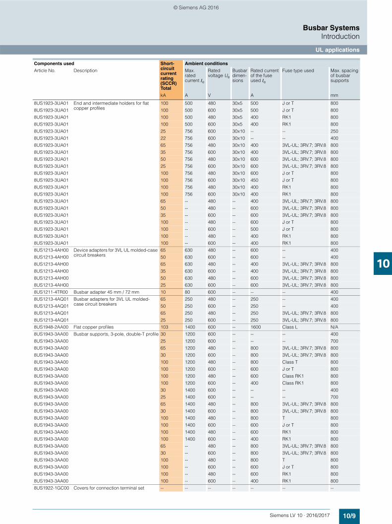
The short-circuit strength of the whole system is dependent on the short-circuit strength of the busbars and of the adapters with circuit breakers or switch disconnectors. If one of these values is lower than the prospective short-circuit current at the installa-tion site, a current-limiting protective device has to be mounted upstream of the 8US busbar system. This may also be mounted as a feeder circuit breaker on the busbar system itself. The table below provides a selection aid for this purpose.
Selection aid for UL applications
Components used Short-circuit current rating (SCCR)Total
Ambient conditions
Article No. Description Max. rated current Ie
Rated voltage Ue
Busbar dimen-sions
Rated current of the fuse used Ie
Fuse type used Max. spacing of busbar supports
kA A V A mm
8US1921-1AA00 Connection terminal plate with cover, conductor cross-section 35 … 120 mm2
10 -- 600 -- -- -- 533
8US1921-1AA00 65 400 480 -- 400 3VL-UL; 3RV.7; 3RV.8 800
8US1921-1AA00 50 600 480 -- 600 3VL-UL; 3RV.7; 3RV.8 800
8US1921-1AA00 35 400 600 -- 400 3VL-UL; 3RV.7; 3RV.8 800
8US1921-1AA00 35 600 600 -- 600 3VL-UL; 3RV.7; 3RV.8 800
8US1921-1AA00 100 600 480 -- 600 J or T 800
8US1921-1AA00 100 500 600 -- 500 J or T 800
8US1921-1AA00 100 400 480 -- 400 RK1 800
8US1921-1AA00 100 400 600 -- 400 RK1 800
8US1922-2AA00 Cover profiles for busbars -- -- -- -- -- -- --
8US1922-2BA00 Cover profiles for busbars -- -- -- -- -- -- --
8US1922-2DA00 Cover profiles for flat copper profile -- -- -- -- -- -- --
8US1923-3UA01 End and intermediate holders for flat copper profiles
18 150 600 12x5 -- -- 250
8US1923-3UA01 18 150 600 12x5 -- -- 400
8US1923-3UA01 65 150 480 12x5 250 3VL-UL; 3RV.7; 3RV.8 800
8US1923-3UA01 25 150 600 12x5 250 3VL-UL; 3RV.7; 3RV.8 800
8US1923-3UA01 100 150 480 12x5 400 RK1, J or T 800
8US1923-3UA01 100 150 600 12x5 175 J or T 800
8US1923-3UA01 100 150 600 12x5 100 RK1 800
8US1923-3UA01 18 150 600 12x10 -- - 250
8US1923-3UA01 18 150 600 12x10 -- - 400
8US1923-3UA01 65 150 480 12x10 250 3VL-UL; 3RV.7; 3RV.8 800
8US1923-3UA01 25 150 600 12x10 250 3VL-UL; 3RV.7; 3RV.8 800
8US1923-3UA01 100 150 480 12x10 400 RK1, J or T 800
8US1923-3UA01 100 150 600 12x10 175 J or T 800
8US1923-3UA01 100 150 600 12x10 100 RK1 800
8US1923-3UA01 18 362 600 20x5 -- - 250
8US1923-3UA01 18 362 600 20x5 -- - 400
8US1923-3UA01 65 362 480 20x5 400 3VL-UL; 3RV.7; 3RV.8 800
8US1923-3UA01 35 362 600 20x5 400 3VL-UL; 3RV.7; 3RV.8 800
8US1923-3UA01 100 362 480 20x5 500 J or T 800
8US1923-3UA01 100 362 600 20x5 400 J or T 800
8US1923-3UA01 100 362 480 20x5 400 RK1 800
8US1923-3UA01 100 362 600 20x5 200 RK1 800
8US1923-3UA01 18 564 600 20x10 -- - 250
8US1923-3UA01 18 564 600 20x10 -- - 400
8US1923-3UA01 65 564 480 20x10 400 3VL-UL; 3RV.7; 3RV.8 800
8US1923-3UA01 35 564 600 20x10 400 3VL-UL; 3RV.7; 3RV.8 800
8US1923-3UA01 100 564 480 20x10 500 J or T 800
8US1923-3UA01 100 564 600 20x10 400 J or T 800
8US1923-3UA01 100 564 480 20x10 400 RK1 800
8US1923-3UA01 100 564 600 20x10 200 RK1 800
8US1923-3UA01 25 500 600 30x5 -- - 250
8US1923-3UA01 22 500 600 30x5 -- - 400
8US1923-3UA01 65 500 480 30x5 400 3VL-UL; 3RV.7; 3RV.8 800
8US1923-3UA01 35 500 600 30x5 600 3VL-UL; 3RV.7; 3RV.8 800
10/8 Siemens LV 10 · 2016/2017
Busbar SystemsIntroduction
UL applications
10
© Siemens AG 2016
8US1923-3UA01 End and intermediate holders for flat copper profiles
100 500 480 30x5 500 J or T 800
8US1923-3UA01 100 500 600 30x5 500 J or T 800
8US1923-3UA01 100 500 480 30x5 400 RK1 800
8US1923-3UA01 100 500 600 30x5 400 RK1 800
8US1923-3UA01 25 756 600 30x10 -- -- 250
8US1923-3UA01 22 756 600 30x10 -- -- 400
8US1923-3UA01 65 756 480 30x10 400 3VL-UL; 3RV.7; 3RV.8 800
8US1923-3UA01 35 756 600 30x10 400 3VL-UL; 3RV.7; 3RV.8 800
8US1923-3UA01 50 756 480 30x10 600 3VL-UL; 3RV.7; 3RV.8 800
8US1923-3UA01 25 756 600 30x10 600 3VL-UL; 3RV.7; 3RV.8 800
8US1923-3UA01 100 756 480 30x10 600 J or T 800
8US1923-3UA01 100 756 600 30x10 450 J or T 800
8US1923-3UA01 100 756 480 30x10 400 RK1 800
8US1923-3UA01 100 756 600 30x10 400 RK1 800
8US1923-3UA01 65 -- 480 -- 400 3VL-UL; 3RV.7; 3RV.8 800
8US1923-3UA01 50 -- 480 -- 600 3VL-UL; 3RV.7; 3RV.8 800
8US1923-3UA01 35 -- 600 -- 600 3VL-UL; 3RV.7; 3RV.8 800
8US1923-3UA01 100 -- 480 -- 600 J or T 800
8US1923-3UA01 100 -- 600 -- 500 J or T 800
8US1923-3UA01 100 -- 480 -- 400 RK1 800
8US1923-3UA01 100 -- 600 -- 400 RK1 800
8US1213-4AH00 Device adapters for 3VL UL molded-case circuit breakers
65 630 480 -- 600 -- 400
8US1213-4AH00 50 630 600 -- 600 -- 400
8US1213-4AH00 65 630 480 -- 400 3VL-UL; 3RV.7; 3RV.8 800
8US1213-4AH00 35 630 600 -- 400 3VL-UL; 3RV.7; 3RV.8 800
8US1213-4AH00 50 630 480 -- 600 3VL-UL; 3RV.7; 3RV.8 800
8US1213-4AH00 25 630 600 -- 600 3VL-UL; 3RV.7; 3RV.8 800
8US1211-4TR00 Busbar adapter 45 mm / 72 mm 10 80 600 -- -- -- 400
8US1213-4AQ01 Busbar adapters for 3VL UL molded-case circuit breakers
65 250 480 -- 250 -- 400
8US1213-4AQ01 50 250 600 -- 250 -- 400
8US1213-4AQ01 65 250 480 -- 250 3VL-UL; 3RV.7; 3RV.8 800
8US1213-4AQ01 25 250 600 -- 250 3VL-UL; 3RV.7; 3RV.8 800
8US1948-2AA00 Flat copper profiles 103 1400 600 -- 1600 Class L N/A
8US1943-3AA00 Busbar supports, 3-pole, double-T profile 30 1200 600 -- -- -- 400
8US1943-3AA00 25 1200 600 -- -- -- 700
8US1943-3AA00 65 1200 480 -- 800 3VL-UL; 3RV.7; 3RV.8 800
8US1943-3AA00 30 1200 600 -- 800 3VL-UL; 3RV.7; 3RV.8 800
8US1943-3AA00 100 1200 480 -- 800 Class T 800
8US1943-3AA00 100 1200 600 -- 600 J or T 800
8US1943-3AA00 100 1200 480 -- 600 Class RK1 800
8US1943-3AA00 100 1200 600 -- 400 Class RK1 800
8US1943-3AA00 30 1400 600 -- -- -- 400
8US1943-3AA00 25 1400 600 -- -- -- 700
8US1943-3AA00 65 1400 480 -- 800 3VL-UL; 3RV.7; 3RV.8 800
8US1943-3AA00 30 1400 600 -- 800 3VL-UL; 3RV.7; 3RV.8 800
8US1943-3AA00 100 1400 480 -- 800 T 800
8US1943-3AA00 100 1400 600 -- 600 J or T 800
8US1943-3AA00 100 1400 480 -- 600 RK1 800
8US1943-3AA00 100 1400 600 -- 400 RK1 800
8US1943-3AA00 65 -- 480 -- 800 3VL-UL; 3RV.7; 3RV.8 800
8US1943-3AA00 30 -- 600 -- 800 3VL-UL; 3RV.7; 3RV.8 800
8US1943-3AA00 100 -- 480 -- 800 T 800
8US1943-3AA00 100 -- 600 -- 600 J or T 800
8US1943-3AA00 100 -- 480 -- 600 RK1 800
8US1943-3AA00 100 -- 600 -- 400 RK1 800
8US1922-1GC00 Covers for connection terminal set -- -- -- -- -- -- --
Components used Short-circuit current rating (SCCR)Total
Ambient conditions
Article No. Description Max. rated current Ie
Rated voltage Ue
Busbar dimen-sions
Rated current of the fuse used Ie
Fuse type used Max. spacing of busbar supports
kA A V A mm
10/9Siemens LV 10 · 2016/2017

UL applications
Busbar SystemsIntroduction
10
© Siemens AG 2016
8US1941-2AA03 Connection terminals, 3-pole 65 400 480 -- 400 3VL-UL; 3RV.7; 3RV.8 800
8US1941-2AA03 35 400 600 -- 400 3VL-UL; 3RV.7; 3RV.8 800
8US1941-2AA03 100 500 480 -- 500 J or T 800
8US1941-2AA03 100 300 600 -- 300 J or T 800
8US1941-2AA03 100 400 480 -- 400 RK1 800
8US1941-2AA03 100 200 600 -- 200 RK1 800
8US1211-1NS10 / 8US1251-5DS10 / 8US1251-5DT11 / 8US1251-5DT10
Busbar device adapters and device holders
5 32 600 -- 12.5 3RV20 + 3RV2928-1K 400
8US1211-1NS10 / 8US1251-5DS10 / 8US1251-5DT11 / 8US1251-5DT10
Busbar device adapters and device holders
5 32 480 -- 32 3RV20 + 3RV2928-1K 400
8US1211-1NS10 / 8US1251-5DS10 / 8US1251-5DT11 / 8US1251-5DT10
Busbar device adapters and device holders
30 32 600 -- 12.5 3RV20 + 3RV2928-1K 400
8US1211-1NS10 / 8US1251-5DS10 / 8US1251-5DT11 / 8US1251-5DT10
Busbar device adapters and device holders
65 32 480 -- 16 3RV20 400
8US1211-1NS10 / 8US1251-5DS10 / 8US1251-5DT11 / 8US1251-5DT10
Busbar device adapters and device holders
65 32 600 -- 25 3RV20 + 3RV2928-1K 400
8US1211-1NS10 / 8US1251-5DS10 / 8US1251-5DT11 / 8US1251-5DT10
Busbar device adapters and device holders
50 32 480 -- 32 3RV20 + 3RV2928-1K 400
8US1211-1NS10 / 8US1251-5DS10 / 8US1251-5DT11 / 8US1251-5DT10
Busbar device adapters and device holders
5 25 600 -- -- -- 400
8US1211-1NS10 / 8US1251-5DS10 / 8US1251-5DT11 / 8US1251-5DT10
Busbar device adapters and device holders
5 32 600 -- -- -- 400
8US1211-1NS10 / 8US1251-5DS10 / 8US1251-5DT11 / 8US1251-5DT10
Busbar device adapters and device holders
5 25 600 -- -- -- 400
8US1211-1NS10 / 8US1251-5DS10 / 8US1251-5DT11 / 8US1251-5DT10
Busbar device adapters and device holders
5 32 600 -- -- -- 400
8US1211-1NS10 / 8US1251-5DS10 / 8US1251-5DT11 / 8US1251-5DT10
Busbar device adapters and device holders
5 25 600 -- -- -- 400
8US1211-1NS10 / 8US1251-5DS10 / 8US1251-5DT11 / 8US1251-5DT10
Busbar device adapters and device holders
5 32 600 -- -- -- 400
8US1251-5NT10 Busbar adapters for devices of size S0 5 30 600 -- -- -- 400
8US1250-1AA10 Device holders for SIRIUS 3RA6 -- -- -- -- -- -- --
8US1250-5AT10 Device holders for devices of width 45 mm
-- -- -- -- -- -- --
8US1250-5AS10 -- -- -- -- -- -- --
Components used Short-circuit current rating (SCCR)Total
Ambient conditions
Article No. Description Max. rated current Ie
Rated voltage Ue
Busbar dimen-sions
Rated current of the fuse used Ie
Fuse type used Max. spacing of busbar supports
kA A V A mm
10/10 Siemens LV 10 · 2016/2017

Busbar Systems8US 40 mm Busbar Systems up to 400 A
Introduction
10
© Siemens AG 2016
■ Overview
The 40 mm busbar system for the lower performance range up to 400 A Terminals and covers for infeed and connection methods
The 40 mm busbar system is used in machine engineering and distribution boards, in meter cabinets and in power distribution systems of the low performance range up to 400 A.
The busbar cross-sections are adapted to the rated currents and are available in the sizes 12 x 5 mm, 12 x 10 mm, 15 x 5 mm and 15 x 10 mm. The basic system is configured without covers. If touch protection is required, this is possible with busbar covers.
Terminals round off the product range of the 40 mm busbar system.
10/11Siemens LV 10 · 2016/2017

Basic assemblies
Busbar Systems8US 40 mm Busbar Systems up to 400 A
10
© Siemens AG 2016
■ Overview
40 mm busbar system: Basic assembly up to 400 A
■ Selection and ordering data
2
3 4
5
1
NSE0_02112
Flat copper profileBusbar supportCover profile
Inlay partCovering cap2
3
45
1
Description DT Article No.www.siemens.com/product?Article No.
Priceper PU
PU(UNIT,
SET, M)
PS*/P. unit
PG Weightper PU
approx.
kg
%() Busbar supports
End and intermediate holders for flat copper profiles
8US1903-3AB00
12 x 5 mm, 12 x 10 mm, 15 x 5 mm, 15 x 10 mm
3-pole, with inside fixing (PU = 2 busbar supports including inlay parts for bar thickness 5 mm and lateral finger-safe covers)
8US1903-3AB00 1 1 unit 1CU 0.176
8US1903-5AA00
5-pole,12 x 5 mm and 12 x 10 mm with inside fixing
L1–L3 + N + PE/N
8US1903-5AA00 1 1 unit 1CU 0.122
8WC5
$ Flat copper profiles (flat profile, approx. 2.4 m long, bare, according to EN 12167)
12 5 mm 8WC5123 1 1 unit 1CU 1.28715 5 mm 8WC5121 1 1 unit 1CU 1.620
& Cover profiles for busbars
8US1922-2CA00
12 5 mm 1000 mm long 8US1922-2CA00 1 10 units 1CU 0.061
15 5 mm 1000 mm long 8US1922-2AA00 1 10 units 1CU 0.150
10/12 Siemens LV 10 · 2016/2017* You can order this quantity or a multiple thereof.

Busbar Systems8US 60 mm Compact Busbar Systems up to 360 A
Introduction
10
© Siemens AG 2016
■ Overview
The 60 mm compact busbar system for the lower performance range up to 360 A
The 60 mm compact busbar system is used especially as a space-saving solution in distribution boards up to 360 A.
Thanks to its maximum height of 160 mm, it offers significant space benefits over other assemblies, and with the comparable dimensions of a 40 mm busbar system it offers an ideal alterna-tive with the benefits of a 60 mm busbar system.
Another important benefit is provided by the option of combining with devices from the basic assemblies up to 400 A.
In addition, most components of the system in the 3-pole version meet the requirement regarding clearances in accordance with UL 508.
Another benefit is expansion to a 5-pole system with the same mounting height of 160 mm. The N and PE conductors are each arranged between the phases. The busbar supports are already prepared for a 5-pole system.
■ Benefits
• Significant space advantage compared to other assemblies • Combination option with devices from the basic assemblies
up to 400 A• Comply with the clearances stipulated by UL 508• Expansion to a 5-pole system possible
10/13Siemens LV 10 · 2016/2017

Basic assemblies
Busbar Systems8US 60 mm Compact Busbar Systems up to 360 A
10
© Siemens AG 2016
■ Overview
The 60 mm compact busbar system for the lower performance range up to 360 A
■ Selection and ordering data
Mounting arrangement of 60 mm compact busbar system 3-pole/5-pole
Description Size Stan-dard
DT Article No.www.siemens.com/product?Article No.
Priceper PU
PU(UNIT,
SET, M)
PS*/P. unit
PG Weightper PU
approx.
mm kg
Busbar supports, 3P+N+PE, with end cover
• Rated voltage Ue:- 690 V AC for IEC applications- 600 V AC for UL 508
• SCCR for UL 508- 5-pole: 22 kA- 3-pole: 36 kA
• Minimum order quantity 10 units
12 x 160 x 45 UL 508 8US1923-5CA02 1 10 units 1CU 0.071
UL spacers, height 18 mm
• For use under 8US1923-5CA02 busbar support
• Minimum order quantity 10 units
12 x 160 x18 8US1922-1CA02 1 10 units 1CU 0.035
Stabilizing modules
• For protecting the N and PE busbars against bending.
• Minimum order quantity 10 units
2 x 160 x 47 8US1928-5CA02 1 10 units 1CU 0.018
Cover profiles
• Minimum order quantity 2 units
700 x 160 x 63 8US1922-2CB02 1 2 units 1CU 0.448
Holders
• For 8US1922-2CB02 cover profile
• Minimum order quantity 10 units
5 x 156 x 55 8US1922-2CA02 1 10 units 1CU 0.018
10/14 Siemens LV 10 · 2016/2017* You can order this quantity or a multiple thereof.
Busbar Systems8US 60 mm Compact Busbar Systems up to 360 A
Infeeds and connection methods
10
© Siemens AG 2016
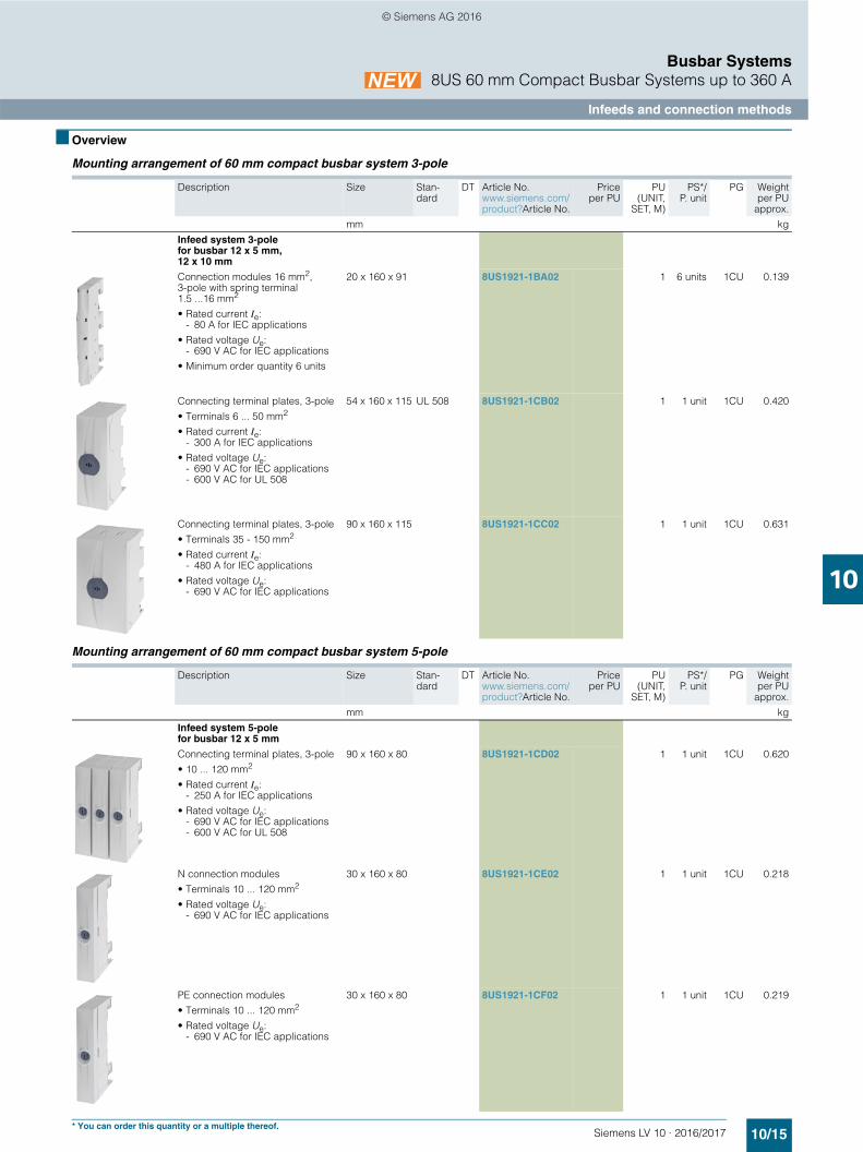
■ Overview
Mounting arrangement of 60 mm compact busbar system 3-pole
Mounting arrangement of 60 mm compact busbar system 5-pole
Description Size Stan-dard
DT Article No.www.siemens.com/product?Article No.
Priceper PU
PU(UNIT,
SET, M)
PS*/P. unit
PG Weightper PU
approx.
mm kg
Infeed system 3-polefor busbar 12 x 5 mm, 12 x 10 mm
Connection modules 16 mm2, 3-pole with spring terminal 1.5 ...16 mm2
• Rated current Ie:- 80 A for IEC applications
• Rated voltage Ue:- 690 V AC for IEC applications
• Minimum order quantity 6 units
20 x 160 x 91 8US1921-1BA02 1 6 units 1CU 0.139
Connecting terminal plates, 3-pole
• Terminals 6 ... 50 mm2
• Rated current Ie:- 300 A for IEC applications
• Rated voltage Ue:- 690 V AC for IEC applications- 600 V AC for UL 508
54 x 160 x 115 UL 508 8US1921-1CB02 1 1 unit 1CU 0.420
Connecting terminal plates, 3-pole
• Terminals 35 - 150 mm2
• Rated current Ie:- 480 A for IEC applications
• Rated voltage Ue:- 690 V AC for IEC applications
90 x 160 x 115 8US1921-1CC02 1 1 unit 1CU 0.631
Description Size Stan-dard
DT Article No.www.siemens.com/product?Article No.
Priceper PU
PU(UNIT,
SET, M)
PS*/P. unit
PG Weightper PU
approx.
mm kg
Infeed system 5-polefor busbar 12 x 5 mm
Connecting terminal plates, 3-pole
• 10 ... 120 mm2
• Rated current Ie:- 250 A for IEC applications
• Rated voltage Ue:- 690 V AC for IEC applications- 600 V AC for UL 508
90 x 160 x 80 8US1921-1CD02 1 1 unit 1CU 0.620
N connection modules
• Terminals 10 ... 120 mm2
• Rated voltage Ue:- 690 V AC for IEC applications
30 x 160 x 80 8US1921-1CE02 1 1 unit 1CU 0.218
PE connection modules
• Terminals 10 ... 120 mm2
• Rated voltage Ue:- 690 V AC for IEC applications
30 x 160 x 80 8US1921-1CF02 1 1 unit 1CU 0.219
10/15Siemens LV 10 · 2016/2017* You can order this quantity or a multiple thereof.

Device adapters and device holders
Busbar Systems8US 60 mm Compact Busbar Systems up to 360 A
10
© Siemens AG 2016
■ Overview
The 60 mm compact busbar system for the lower performance range up to 360 A: Device adapters and device holders
Mounting arrangement of 60 mm compact busbar system 3-pole
Description Size(H x W x D)
Stan-dard
DT Article No.www.siemens.com/product?Article No.
Priceper PU
PU(UNIT,
SET, M)
PS*/P. unit
PG Weightper PU
approx.
mm kg
Adapters, 3-pole
8US1651-5DK02
Adapters 32 A, 1 support rail
• Rated current Ie:- 32 A for IEC applications- 25 A for UL 508
• Rated voltage Ue:- 690 V AC for IEC applications- 600 V AC for UL 508
• Minimum order quantity 4 units
160 x 45 x 63 UL 508 8US1651-5DK02 1 4 units 1CU 0.219
8US1651-5FK02
Adapters 63 A, 1 support rail
• Rated current Ie:- 63 A for IEC applications- 65 A for UL 508
• Rated voltage Ue:- 690 V AC for IEC applications- 600 V AC for UL 508
• Minimum order quantity 4 units
160 x 54 x 63 UL 508 8US1661-5FK02 1 4 units 1CU 0.287
Device holders
8US1613-4AU01
Adapters for molded case circuit breakers
• With latching function
• For rails 12 x 5 mm, 12 x 10 mm
• Rated current Ie:- 144 A for IEC applications
• Rated voltage Ue:- 690 V AC for IEC applications
160 x 77 8US1613-4AU01 1 1 unit 1CU 0.539
10/16 Siemens LV 10 · 2016/2017* You can order this quantity or a multiple thereof.

Busbar Systems8US 60 mm Compact Busbar Systems up to 360 A
Device adapters and device holders
10
© Siemens AG 2016
Mounting arrangement of 60 mm compact busbar system 5-pole
Description Size Stan-dard
DT Article No.www.siemens.com/product?Article No.
Priceper PU
PU(UNIT,
SET, M)
PS*/P. unit
PG Weightper PU
approx.
mm kg
Adapters for 5-pole compact busbar system
8US1621-2NJ02
Adapters, single-pole, 32 A
• Standard version
• Rated current Ie:- 32 A for IEC applications
• Rated voltage Ue:- 690 V AC for IEC applications
• Minimum order quantity 12 units
18 x 160 x 73 8US1621-2NJ02 1 12 units 1CU 0.073
8US1621-2FK02
Adapters, single-pole, 63 A
• Standard version
• Rated current Ie:- 63 A for IEC applications
• Rated voltage Ue:- 690 V AC for IEC applications
• Minimum order quantity 12 units
18 x 160 x 73 8US1621-2FK02 1 12 units 1CU 0.075
8US1624-2FK02
Adapters, single-pole, 63 A
• For 5SL, 5SY miniature circuit breakers
• Rated current Ie:- 63 A for IEC applications
• Rated voltage Ue:- 690 V AC for IEC applications
• Minimum order quantity 12 units
18 x 160 x 82 8US1624-2FK02 1 12 units 1CU 0.840
10/17Siemens LV 10 · 2016/2017* You can order this quantity or a multiple thereof.

Accessories
Busbar Systems8US 60 mm Compact Busbar Systems up to 360 A
10
© Siemens AG 2016
■ Overview
For 12 x 5 mm busbars
Description Size Stan-dard
DT Article No.www.siemens.com/product?Article No.
Priceper PU
PU(UNIT,
SET, M)
PS*/P. unit
PG Weightper PU
approx.
mm kg
8US1600-0RE02
N modules
• Terminals 1.5 ... 16 mm2
• Rated voltage Ue:- 690 V AC for IEC applications
• Minimum order quantity 12 units
9 x 160 x 114 8US1600-0RE02 1 12 units 1CU 0.063
8US1600-0RF02
PE modules
• Terminals 1.5 ... 16 mm2
• Rated voltage Ue:- 690 V AC for IEC applications
• Minimum order quantity 12 units
9 x 160 x 114 8US1600-0RF02 1 12 units 1CU 0.062
8US1620-5AK02
Support modules
• Minimum order quantity 6 units
18 x 160 x 54 8US1620-5AK02 1 6 units 1CU 0.039
8US1998-2BH02
Lateral modules
• Minimum order quantity 12 units
9 x 160 x 47 8US1998-2BH02 1 12 units 1CU 0.023
8US1998-1AA02
Set of connectors
• For connecting adapters
-- 8US1998-1AA02 1 1 unit 1CU
10/18 Siemens LV 10 · 2016/2017* You can order this quantity or a multiple thereof.

Busbar Systems8US 60 mm Busbar Systems up to 1600 A
Introduction
10
© Siemens AG 2016
■ Overview
The 60 mm busbar system for the medium and top performance range up to 1600 A, here for example with the 3NP1 switch disconnector, size 3
The 60 mm busbar system is used preferably in control cabinet installation, in motor control centers and in power distribution systems of the medium power range (630 A) and top perfor-mance range (1600 A, special profile).
The 60 mm busbar system can be configured as a basic system without covers. The busbar cross-sections are available in the sizes 12 x 5 mm to 30 x 10 mm and as a special profile.
Busbar adapters for SIRIUS devices, 3VL circuit breakers, 3KA and 3KL switch disconnectors, and 3NP1 and 3NP5 fuse switch disconnectors offer numerous options for configuring this bus-bar system. Infeed units, terminals and other accessories open up a large range of applications.
Busbars with a special profile are suitable for applications up to 1600 A. All components of the 60 mm busbar system can be fitted.
SIRIUS motor starter combinations
SIRIUS motor starter combinations can be configured with and without fuses.
The compact 3NW7 ... -1 cylindrical fuse holders for IEC fuses, size 10 x 38 mm, or 3NW7... -1HG cylindrical fuse holders for Class CC UL fuses are suitable for use with fused motor starter combinations.
With a width of 45 mm, SIRIUS motor starter combinations are the same width as the majority of contactors.
For further information and accessories, see chapter "Fuse systems" ➞ Cylindrical fuse systems➞ Fuse holders in size 10 x 38 mm and Class CC
Installation configuration of a cylindrical fuse holder and a SIRIUS contactor on busbar device adapter for the 60 mm busbar system
10/19Siemens LV 10 · 2016/2017

Basic assemblies up to 630 A
Busbar Systems8US 60 mm Busbar Systems up to 1600 A
10
© Siemens AG 2016
■ Overview
60 mm busbar system: Basic assemblies up to 630 A
■ Selection and ordering data
Busbar support and end cover
NS
E0_
0212
3
Blanking cover
Support for blanking covers
Cover profile
End cover
Busbar supports
Flat copper profile
Description Connections Standard DT Article No.www.siemens.com/product?Article No.
Priceper PU
PU(UNIT,
SET,M)
PS*/P. unit
PG Weightper PU
approx.
kg
% Busbar supports
End and intermediate holders for flat copper profiles 12, 15, 20, 25, 30 x 5, 10 mm
3-pole, with outside fixing
L1–L3 8US1923-2AA01 1 10 units 1CU 0.161
8US1923-3AA01
3-pole, with inner fixing
L1–L3 8US1923-3AA01 1 10 units 1CU 0.156
4-pole, with inner fixing
L1–L3 + PE/N 8US1923-4AA00 1 10 units 1CU 0.233
8US1923-5AA00
2-pole, with outside fixing
8US1923-5AA00 1 10 units 1CU 0.112
N/PE busbar supports 12, 20, 30 x 5, 10 mm
5SH3540
1-pole, for flat copper profilefor 5/10 mm busbars
PE/N 5SH3540 1 1 unit 1CU 0.070
10/20 Siemens LV 10 · 2016/2017* You can order this quantity or a multiple thereof.

Busbar Systems8US 60 mm Busbar Systems up to 1600 A
Basic assemblies up to 630 A
10
© Siemens AG 2016
Covers, supports for blanking covers, flat copper profiles and busbar connection parts
8US1923-1AA01
N/PE busbar supports, 6 x 6 mm12, 15, 20, 25, 30 x 5, 10 mm
1-pole, for copper profiles for mounting on 8US1923-2AA01 3-pole busbar supports or free standing
PE/N UL 508 8US1923-1AA01 1 1 unit 1CU 0.052
8US1923-3UA01
End and intermediate holders for flat copper profiles 5 x 20 mm, 10 x 20 mm, 10 x 30 mm
3-pole, with inner fixing
L1–L3 UL 5081) 8US1923-3UA01 1 10 units 1CU 0.154
8US1922-1AC00
& End covers
For covering free busbar ends
• For 8US1923-2AA01, 3AA01 and 3UA01
L1–L3 UL 508 8US1922-1AC00 1 10 units 1CU 0.020
1) Only with base plate 8US1922-2UA01
Description Length Width Depth Stan-dard
DT Article No.www.siemens.com/product?Article No.
Priceper PU
PU(UNIT,
SET,M)
PS*/P. unit
PG Weightper PU
approx.
mm mm mm kg
( Cover profiles for busbars
8US1922-2CA00
12 5 mm 1000 15 10 8US1922-2CA00 1 10 units 1CU 0.061
8US1922-2AA00
15 5 mm, 20 5 mm,25 5 mm, 30 5 mm
1000 40 9 UL 508 8US1922-2AA00 1 10 units 1CU 0.150
12 10 mm, 15 10 mm, 20 10 mm, 25 10 mm, 30 10 mm
1000 40 14 UL 508 8US1922-2BA00 1 10 units 1CU 0.175
8US1922-2EA0.
) Supports for blanking covers
Mounting on busbar, 32 mm depth (2 units per section of blanking cover)
UL 508 8US1922-2EA00 1 4 units 1CU 0.038
Mounting on busbar, 107 mm depth (2 units per section of blanking cover)
UL 508 8US1922-2EA01 1 8 units 1CU 0.081
8US1922-2EB00
* Blanking covers
Mounting on 8US1922-2EA.. support for blanking covers Height 195 mm, Depth 63 mm, Length 700 mm
UL 508 8US1922-2EB00 1 2 units 1CU 0.741
Description Connections Standard DT Article No.www.siemens.com/product?Article No.
Priceper PU
PU(UNIT,
SET,M)
PS*/P. unit
PG Weightper PU
approx.
kg
10/21Siemens LV 10 · 2016/2017* You can order this quantity or a multiple thereof.

Basic assemblies up to 630 A
Busbar Systems8US 60 mm Busbar Systems up to 1600 A
10
© Siemens AG 2016
Description Length Cross-section
Standard DT Article No.www.siemens.com/product?Article No.
Priceper PU
PU(UNIT,
SET, M)
PS*/P. unit
PG Weightper PU
approx.
mm mm2 kg
8US1922-2UA01
Base plates
For 3-pole system, width 240 mm
1100 -- UL 508 8US1922-2UA01 1 2 units 1CU 0.563
$ Flat copper profiles (flat profile, bare)
Flat copper profiles for universal applications
• 12 5 mm, current intensity 200 A
2400 60 EN 12167 8WC5123 1 1 unit 1CU 1.287
• 15 5 mm, current intensity 250 A
2400 75 EN 12167 8WC5121 1 1 unit 1CU 1.620
• 20 5 mm, current intensity 320 A
2400 100 EN 12167 8WC5126 1 1 unit 1CU 2.000
• 20 5 mm, current intensity 400 A
1100 125 EN 12167 8WC5031-1AA00 1 1 unit 1CU 1.229
• 25 5 mm, current intensity 400 A
2400 125 EN 12167 8WC5131 1 1 unit 1CU 2.670
• 30 5 mm, current intensity 447 A
1100 150 EN 12167 8WC5033-1AA00 1 1 unit 1CU 1.500
• 30 5 mm, current intensity 447 A
2400 150 EN 12167 8WC5133 1 1 unit 1CU 3.000
• 20 10 mm, current intensity 520 A
2400 200 EN 12167 8WC5128 1 1 unit 1CU 4.120
• 30 10 mm, current intensity 630 A
2400 300 EN 12167 8WC5134 1 1 unit 1CU 6.500
$ Flat copper profiles, tinned
• 12 5 mm, current intensity 200 A
2000 60 EN 12167 8WC5051 1 1 unit 1CU 1.072
• 15 5 mm, current intensity 250 A
2000 75 EN 12167 8WC5052 1 1 unit 1CU 1.328
• 20 5 mm, current intensity 320 A
2000 100 EN 12167 8WC5053 1 1 unit 1CU 1.788
• 25 5 mm, current intensity 400 A
2000 125 EN 12167 8WC5054 1 1 unit 1CU 2.290
• 30 5 mm, current intensity 447 A
2000 150 EN 12167 8WC5055 1 1 unit 1CU 2.682
• 20 10 mm, current intensity 520 A
2000 200 EN 12167 8WC5063 1 1 unit 1CU 3.576
• 30 10 mm, current intensity 630 A
2000 300 EN 12167 8WC5065 1 1 unit 1CU 5.364
For further flat copper profiles, see chapter "Distribution Boards / Power Distribution Boards"
8JK320
Extension terminals
For busbars 12 5 mm, tightening torque 6.0 Nm (busbar not included, 1 set = 2 units)
-- -- -- 8JK3201 1 10 sets 1BR 0.020
Busbar connection pieces for bars
8US1921-2BE00
For flat profiles (max. 630 A)
20 5 mm, 20 10 mm, 25 5 mm, 25 10 mm,30 5 mm, 30 10 mm
40 -- -- 8US1921-2BE00 1 6 units 1CU 0.234
8US1921-2BF00
For flat profiles (max. 630 A)
12 5 mm, 12 10 mm, 15 5 mm, 15 10 mm,20 5 mm, 20 10 mm
55 -- -- 8US1921-2BF00 1 12 units 1CU 0.160
10/22 Siemens LV 10 · 2016/2017* You can order this quantity or a multiple thereof.

Busbar Systems8US 60 mm Busbar Systems up to 1600 A
Basic assemblies up to 1600 A
10
© Siemens AG 2016
■ Overview
60 mm busbar system: Basic assembly up to 1600 A
■ Selection and ordering data
End cover
Busbar support
Flat copper profileN
SE
0_02
113
Description Standard DT Article No.www.siemens.com/product?Article No.
Priceper PU
PU(UNIT,
SET, M)
PS*/P. unit
PG Weightper PU
approx.
kg
8US1943-3AA00
Busbar supports
3-pole, for TT special profilesEnd and intermediate holder with finger-safe busbar cover (1 pack = 2 busbar supports + finger-safe end covers)
L1–L3 UL 508 8US1943-3AA00 1 1 unit 1CU 1.084
8US1948-2AA00
Flat copper profiles (approx. 2.4 m long, tinned)
TT special profile up to 1600 A, cross-section 720 mm2
8US1948-2AA00 1 1 unit 1CU 15.600
8US1948-2AA00
Cover profiles
For flat copper profiles, length 1000 mm 8US1922-2DA00 1 5 units 1CU 0.482
8US1941-2BF00
Busbar connection pieces
For special profiles/TT profiles up to 1600 A 8US1941-2BF00 1 3 units 1CU 1.137
8US1922-1JA00
Partitions, closed76 mm wide, 2400 mm longFor additional lateral touch protection at the top/bottom
8US1922-1JA00 1 1 unit 1CU 0.500
8US1922-2EA0.
Supports for blanking covers
Mounting on busbar, 32 mm depth (2 units per section of blanking cover)
UL 508 8US1922-2EA00 1 4 units 1CU 0.038
Mounting on busbar, 107 mm depth (2 units per section of blanking cover)
UL 508 8US1922-2EA01 1 8 units 1CU 0.081
8US1922-2EB00
Blanking covers
Mounting on 8US1922-2EA.. support for blanking covers Height 195 mm, Depth 63 mm, Length 700 mm
UL 508 8US1922-2EB00 1 2 units 1CU 0.741
48
76
2400
10/23Siemens LV 10 · 2016/2017* You can order this quantity or a multiple thereof.

Infeed and connection methods
Busbar Systems8US 60 mm Busbar Systems up to 1600 A
10
© Siemens AG 2016
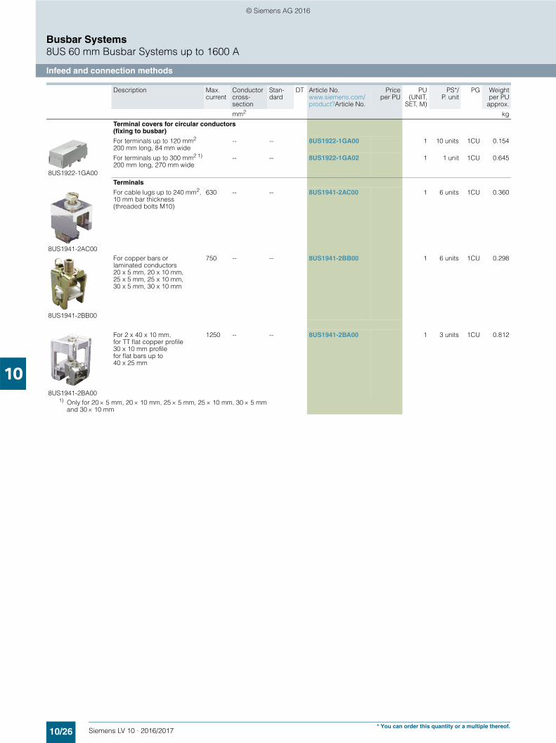
■ Overview
60 mm busbar system: Terminals and covers for infeed and connection methods
■ Selection and ordering data
Description Length Width Max.current
Conductor cross-section
Stan-dard
DT Article No.www.siemens.com/product?Article No.
Priceper PU
PU(UNIT,
SET, M)
PS*/P. unit
PG Weightper PU
approx.
mm mm A mm2 kg
8US1921-1AA00
Infeeds
Connecting terminal plate with cover
• 3-pole 200 20 80 1.5 ...16 UL 508 5SH3538 1 5 units 1CU 0.157
• 3-pole 200 54 300 6 ... 50 UL 508 8US1921-1BA00 1 1 unit 1CU 0.417
• 3-pole 200 81 400 35 ... 120 UL 508 8US1921-1AA00 1 1 unit 1CU 0.496
8US1200-0AA00
Outgoing modules for PE/N
Connection module for 4th pole (PE/N) up to 16 mm, must be attached to an adapter/device holder
242 18 -- -- -- 8US1200-0AA00 1 1 unit 1CU 0.129
5SH3535
SR60 connecting terminal plates
3-pole with cover, suitable for aluminum conductors(shown with-out cover)
560 150 ... 300 -- 5SH3535 1 1 unit 1CU 1.643
8US1941-2AA03
Terminal sets
3-pole with-out cover for round cables, suitable for aluminum conductors
560 95 ... 300 UL 508 8US1941-2AA03 1 1 unit 1CU 1.560
10/24 Siemens LV 10 · 2016/2017* You can order this quantity or a multiple thereof.

Busbar Systems8US 60 mm Busbar Systems up to 1600 A
Infeed and connection methods
10
© Siemens AG 2016
Description Max.current
Conductor cross-section
Stan-dard
DT Article No.www.siemens.com/product?Article No.
Priceper PU
PU(UNIT,
SET, M)
PS*/P. unit
PG Weightper PU
approx.
mm2 kg
8US1941-2AA04
Terminal sets
3-pole without coverfor flat bars up to32 x 20 mm
800 -- UL 508 8US1941-2AA04 1 1 unit 1CU 1.339
8US1922-1GC00
Covers for 8US1941-2AA03/04 terminal set
-- -- -- 8US1922-1GC00 1 1 unit 1CU 0.347
Terminals for circular conductors
5 mm busbar thickness1)
Terminals
12 5 mm, 15 5 mm, 20 5 mm, 25 5 mm, 30 5 mm
180 1.5 ... 16 8US1921-2AA00 100 100 units 1CU 2.060270 4 ... 35 8US1921-2AB00 100 50 units 1CU 4.600400 16 ... 70 8US1921-2AD00 1 50 units 1CU 0.071440 16 ... 120 8US1921-2AC00 1 50 units 1CU 0.106
180 1.5 ... 16 8US1921-2AA01 1 15 units 1CU 0.021270 4 ... 35 8US1921-2AB01 1 15 units 1CU 0.046400 16 ... 70 8US1921-2AD01 1 15 units 1CU 0.070440 16 ... 120 8US1921-2AC01 1 15 units 1CU 0.100
10 mm busbar thickness
Terminals
12 10 mm,1) 15 10 mm,1) 20 10 mm, 25 10 mm, 30 10 mm
180 1.5 ... 16 8US1921-2BA00 1 100 units 1CU 0.022270 4 ... 35 8US1921-2BB00 1 50 units 1CU 0.048
400 16 ... 70 8US1921-2BD00 1 50 units 1CU 0.072
440 16 ... 120 8US1921-2BC00 1 50 units 1CU 0.107
180 1.5 ... 16 8US1921-2BA01 1 15 units 1CU 0.022270 4 ... 35 8US1921-2BB01 1 15 units 1CU 0.048
400 16 ... 70 8US1921-2BD01 1 15 units 1CU 0.070440 16 ... 120 8US1921-2BC01 1 15 units 1CU 0.104
20 5 mm, 25 5 mm, 30 5 mm
8US1941-2AA01
500 95 ... 185 8US1941-2AA01 1 6 units 1CU 0.307
8US1941-2AA02
600 95 ... 300 8US1941-2AA02 1 3 units 1CU 0.406
1) Cannot be used on a special profile up to 1600 A
10/25Siemens LV 10 · 2016/2017* You can order this quantity or a multiple thereof.
Infeed and connection methods
Busbar Systems8US 60 mm Busbar Systems up to 1600 A
10
© Siemens AG 2016
Terminal covers for circular conductors (fixing to busbar)
8US1922-1GA00
For terminals up to 120 mm2
200 mm long, 84 mm wide-- -- 8US1922-1GA00 1 10 units 1CU 0.154
For terminals up to 300 mm2 1)
200 mm long, 270 mm wide-- -- 8US1922-1GA02 1 1 unit 1CU 0.645
Terminals
8US1941-2AC00
For cable lugs up to 240 mm2, 10 mm bar thickness(threaded bolts M10)
630 -- -- 8US1941-2AC00 1 6 units 1CU 0.360
8US1941-2BB00
For copper bars or laminated conductors20 x 5 mm, 20 x 10 mm, 25 x 5 mm, 25 x 10 mm, 30 x 5 mm, 30 x 10 mm
750 -- -- 8US1941-2BB00 1 6 units 1CU 0.298
8US1941-2BA00
For 2 x 40 x 10 mm, for TT flat copper profile 30 x 10 mm profile for flat bars up to 40 x 25 mm
1250 -- -- 8US1941-2BA00 1 3 units 1CU 0.812
1) Only for 20 5 mm, 20 10 mm, 25 5 mm, 25 10 mm, 30 5 mm and 30 10 mm
Description Max.current
Conductor cross-section
Stan-dard
DT Article No.www.siemens.com/product?Article No.
Priceper PU
PU(UNIT,
SET, M)
PS*/P. unit
PG Weightper PU
approx.
mm2 kg
10/26 Siemens LV 10 · 2016/2017* You can order this quantity or a multiple thereof.

Busbar Systems8US 60 mm Busbar Systems up to 1600 A
Built-in components
10
© Siemens AG 2016
■ Overview
Rail-adaptable built-in components, such as NEOZED and DIAZED bus-mounting bases, adapters for modular installation devices, fuse switch disconnectors and NEOZED bus-mounting fuse switch disconnectors are made of glass-fiber reinforced, thermoplastic polyester. The material ensures the required mechanical, chemical and electrical properties.
Efficient power distribution up to 630 A. Users have several options for mounting the SR60 busbar system:
1. Mounting in distribution boards
The busbar supports are mounted on the longitudinal stays. Once the built-in components are mounted and connected, the touch protection cover (section cover) protects against acciden-tal contact with live parts.
2. Installation in industrial control cabinets
The demand for comprehensive touch protection has generated new solutions: Built-in components, such as busbar fuse bases have integrated reach-through guards, enable the implementa-tion of cost-effective overall solutions.
Previously two optional solutions were provided, which can now be replaced using new technology: Touch protection over base and edges or touch protection over partitions.
Higher overall efficiency and cost savings in the plant engineering industry.
The fuse holders for cylindrical fuses, size 10 x 38 and for American fuses, Class CC, can be used in the international plant engineering industry. In addition, Siemens offers a broad range of UL-approved components for the design of switchboards according to UL 508 A.
Fuse holders, fuse switch disconnectors, switch disconnectors with fuse and 16 mm² connection modules with screwless termi-nals are available; this offers users maximum safety and comfort.
Planning dimensions
Widthmm MW
NEOZED bus-mounting bases D02Covers 27 1.5Covers, extra wide 36 2.0Covers, double width 54 3.0
DIAZED bus-mounting bases DIICovers 42 2.3
DIAZED bus-mounting bases DIIICovers 57 3.2
NEOZED bus-mounting switch disconnectors 27 1.5
LV HRC fuse switch disconnectors size 00 108 6
Bus-mounting fuse holders 27 1.5
10/27Siemens LV 10 · 2016/2017

Built-in components
Busbar Systems8US 60 mm Busbar Systems up to 1600 A
10
© Siemens AG 2016
■ Benefits
• The direct contact of the rail-adaptable switching and installa-tion devices on the Cu busbars reduces distribution panels and mounting times
• Compared to conventional installation, the transfer resistance of the connections is drastically reduced. This prevents un-necessary temperature rise
• New built-in components with touch protection ensure com-prehensive touch protection without the previously required partitions
• International application due to UL-approved components• Enhanced effectiveness and increased safety due to screw-
less terminals.
I201
_136
34a
4
5
3
6
7
2
1
NEOZED bus-mounting bases, 3-poleDIAZED bus-mounting bases, 3-poleSR60 bus-mounting fuse holders, 3-poleNEOZED bus-mounting switch disconnectors, 3-poleConnection modules, three-phaseAdapters for modular installation devices according to DIN 43880LV HRC fuse switch disconnectors
123456
7
10/28 Siemens LV 10 · 2016/2017

Busbar Systems8US 60 mm Busbar Systems up to 1600 A
Built-in components
10
© Siemens AG 2016
■ Technical specifications
1) In the case of permanent load over 35 A, we recommend the use of 5SH5526 lateral modules. Please observe EN 60439-1, Table 1.
Bus-mounting bases NEOZED SR60 bus-mounting bases
DIAZED SR60 bus-mounting bases
5SG6202 5SG6206 5SG62075SG208
5SF6014 5SF6015 5SF6020
5SF6214 5SF6215 5SF6220
D01 D02 DII DIII
Standards IEC 60269-3, DIN VDE 0636-3
Rated voltage V AC 400 500 690V DC 250 -- 600
Rated frequency Hz 50
Rated current A 16 (with 5SH5400 retaining springs)
63 25 63
Rated conditional short-circuit current kA AC 50 50kA DC 8 8
For fuse links with power losses per phase W 2.5 5.5 4 7
Busbar center-to-center spacing mm 60 60
Bus-mounting fuse holders 3NW7431 3NW7431-0HG
Standards IEC 60269-2, UL 512, CSA C22.2
UL 512, CSA C22.2
Approvals U, CSA UL, CSA
Size 10 × 38 Class CC
Rated frequency Hz 50/60
Max. rated voltage Ue• IEC/EN V AC 690 --• UL/CSA V AC 600 600
Max. rated current Ie(When several devices are used next to each other, it is essential to comply with the rated load factor according to EN 60439-1 (VDE 0660-500), Table 1.)• IEC/EN A 32 --• UL/CSA A 30 30
Utilization categories• IEC/EN AC-22B (500 V)
AC-21B (690 V, 30 A)• UL/CSA Can only be used as fuse holder
Rated conditional short-circuit current(type-tested with fuse links, operational class gL/gG)• IEC/EN kA 100 (400 V, 500 V, 690 V) --• UL/CSA kA 50 (600 V) 200
For fuse links with power losses per phase W 3 --
Screwless wire connections• IEC/EN mm2 Cu 1.5 … 6 (f)• UL/CSA AWG 16 … 10 (str)
Bus-mounting switch disconnectors with fuses 5SG7230 3NW7430
Standards IEC 60269-3, IEC 60269-2
Approvals EN 60947-3 (VDE 0660-107), IEC 60947-3
Size D02 (D01) 10 mm × 38 mm
Rated frequency Hz 50/60 50/60
Rated voltage Ue V AC 400 690V DC 110 --
Rated insulation voltage Ui V 800 800
Rated impulse withstand voltage Uimp kV 6 6
Rated current Ie A 631) Up to 32
Utilization categories AC-23 A (400 V) AC-20(Type-tested with 3-pole, switchable version) DC-21 B (48 V), 1 pole DC-20
DC-21 B (110 V), 2 pole
Box terminals for wire connection mm2 Cu 1.5 … 6 (re) Cu 1.5 … 6 (re)mm2 Cu 1.5 … 16 (f) Cu 1.5 … 16 (f)mm2 Cu 1.5 … 16 (f+AE) Cu 1.5 … 16 (f+AE)
Signaling switches for the display of switching positions 1 CO 1 CO
Cable terminals Bottom Bottom
Busbar thickness mm Through combination foot for 5, 10 mm
Rated conditional short-circuit current kA AC 50 50(type-tested with fuse links, operational class gL/gG) kA DC 8 --
Permissible power loss of fuse links per phase W 5.5 3For stand-alone operation without lateral modules or for group operation with lateral modules
10/29Siemens LV 10 · 2016/2017

Built-in components
Busbar Systems8US 60 mm Busbar Systems up to 1600 A
10
© Siemens AG 2016
■ Selection and ordering data
Size Rated current Rated voltage Mount-ing width
DT Article No.www.siemens.com/product?Article No.
Priceper PU
PU(UNIT,
SET,M)
PS*/P. unit
PG Weightper PU
approx.
A V MW kg
NEOZED SR60 bus-mounting bases with touch protection, 3P For 5/10 mm busbars
27 mm wide
D02 63 400 1.5 5SG6206 1 4 units 1CU 0.146
36 mm wide
D02 63 400 2 5SG6207 1 4 units 1CU 0.163
NEOZED SR60 bus-mounting bases, 3P standard versionFor 5/10 mm busbars
D02 63 400 1.5 5SG6202 1 4/104 units 1CU 0.111
NEOZED SR60 covers for standard version
D02 1.5 5SH5241 1 4/200 units 1CU 0.024
D02, extra wide 2 5SH5242 1 4/140 units 1CU 0.028
D02, with double width 3 5SH5243 1 4/120 units 1CU 0.039
DIAZED SR60 bus-mounting bases with touch protection, 3P
For use with DIAZED screw adaptersDII 25 500 2.3 5SF6020 1 4 units 1CU 0.295DIII 63 500 V AC/DC
(according to DIN VDE 0636-3 also 690 V AC/600 V DC)
3.2 5SF6220 1 4 units 1CU 0.397
. For NEOZED screw caps, NEOZED adapter sleeves and NEOZED fuse links, see chapter "Fuse Systems", "NEOZED fuse systems"
DIAZED SR60 bus-mounting bases, 3P standard version
For use with DIAZED screw adaptersDII 25 500 2.3 5SF6015 1 2/52 units 1CU 0.233DIII 63 500 V AC/DC
(according to DIN VDE 0636-3 also 690 V AC/600 V DC)
3.2 5SF6215 1 2/52 units 1CU 0.308
10/30 Siemens LV 10 · 2016/2017

Busbar Systems8US 60 mm Busbar Systems up to 1600 A
Built-in components
10
© Siemens AG 2016
Other accessories
DIAZED SR60 covers for standard version
DII 2.3 5SH2042 1 2/120 units 1CU 0.048DIII 3.2 5SH2242 1 2/120 units 1CU 0.059
SR60 bus-mounting fuse holders, 3P For 5/10 mm busbars with screwless terminals
For cylindrical fuses, 10 × 38 mm U, s-- 30 690 1.5 3NW7431 1 1 unit 1CU 0.249
For UL fuses, Class CC u, s-- 30 600 1.5 3NW7431-0HG 1 1 unit 1CU 0.256
NEOZED SR60 bus-mounting switch disconnectors, 3PFor 5/10 mm busbars
D02 63* 400 1.5 5SG7230 1 1/30 units 1CU 0.698* From 35 A load use 5SH5526 lateral module
DIAZED screw caps, DIAZED screw adapters and DIAZED fuse links see chapter "Fuse Systems", "DIAZED fuse system"
Version Mount-ing width
DT Article No.www.siemens.com/product?Article No.
Priceper PU
PU(UNIT,
SET,M)
PS*/P. unit
PG Weightper PU
approx.
MW kg
5SH5525
Auxiliary switches for signaling the switching state for NEOZED SR60 bus-mounting switch disconnectors (5SG7230)
1 CO 0.5 5SH5525 1 1/50 units 1CU 0.008
5SH5526
Lateral modules
For greater heat dissipation for loads from 35 A with NEOZED bus-mounting switch disconnectors
0.5 5SH5526 1 5/50 units 1CU 0.066
5SH5527
Reducers
For NEOZED fuse links D01In SR60 bus-mounting switch disconnectors -- 5SH5527 1 10/100 units 1CU 0.001
Size Rated current Rated voltage Mount-ing width
DT Article No.www.siemens.com/product?Article No.
Priceper PU
PU(UNIT,
SET,M)
PS*/P. unit
PG Weightper PU
approx.
A V MW kg
10/31Siemens LV 10 · 2016/2017

Device adapters and device holders
Busbar Systems8US 60 mm Busbar Systems up to 1600 A
10
© Siemens AG 2016
■ Overview
60 mm busbar system: Busbar device adapters and device holders
All busbar device adapters and device holders are designed for copper busbars according to DIN 46433, width 12 to 30 mm, thickness 5 mm and 10 mm, and special profiles up to 1600 A.
■ Selection and ordering data
For SIRIUS 3RV2/3RT2 load feeders
Welded connecting cable resistant up to 150 °C
Busbar device adapters for
Number of sup-port rails (35 mm)
Adapter Connecting cable Stan-dard
DT Article No.www.siemens.com/product?Article No.
Priceper PU
PU(UNIT,
SET, M)
PS*/P. unit
PG Weightper PU
approx.Length Width Cross-sec-tion
Tem-pera-turemax.
Rated cur-rent
Rated volt-age
mm mm AWG °C A V kg
Device holders with 3RA2120
Size S00 devices with screw connection
Circuit breakers
1 200 45 12 150 25 6906001)
UL 508 8US1251-5DS10 1 1 unit 1CU 0.285
Direct-on-line starters
1 200 45 12 150 25 6906001)
UL 508 8US1251-5DS10 1 1 unit 1CU 0.285
1 260 45 12 150 25 6906001)
UL 508 8US1251-5DT10 1 1 unit 1CU 0.312
Reversing starters
1 200 45 12 150 25 6906001)
UL 508 8US1251-5DS10 1 1 unit 1CU 0.285
+ +
Device holders
1 200 45 -- -- -- -- UL 508 8US1250-5AS10 1 1 unit 1CU 0.217
Device holders with 3RA2120
Size S00 devices with screw connection
Circuit breakers
1 200 45 12 150 25 6906001)
UL 508 8US1251-5DS11 1 1 unit 1CU 0.315
Circuit breakers
1 260 45 12 150 25 6906001)
UL 508 8US1251-5DT11 1 1 unit 1CU 0.330
Direct-on-line starters
1 260 45 12 150 25 6906001)
UL 508 8US1251-5DT11 1 1 unit 1CU 0.330
Reversing starters
1 260 45 12 150 25 6906001)
UL 508 8US1251-5DT11 1 1 unit 1CU 0.330
+ +
Device holders
1 260 45 -- -- -- -- UL 508 8US1250-5AT10 1 1 unit 1CU 0.244
1) Value applies to UL 508
10/32 Siemens LV 10 · 2016/2017* You can order this quantity or a multiple thereof.

Busbar Systems8US 60 mm Busbar Systems up to 1600 A
Device adapters and device holders
10
© Siemens AG 2016
1) Value applies to UL 508
Size S0 devices with screw connection
Device holderswith 3RA2220
Circuit breakers
1 200 45 12 150 25 6906001)
UL 508 8US1251-5DS10 1 1 unit 1CU 0.285
Circuit breakers
1 260 45 10 150 32 6906001)
UL 508 8US1251-5NT10 1 1 unit 1CU 0.334
Direct-on-line starters
1 260 45 10 150 32 6906001)
UL 508 8US1251-5NT10 1 1 unit 1CU 0.334
Reversing starters
1 260 45 10 150 32 6906001)
UL 508 8US1251-5NT10 1 1 unit 1CU 0.334
+ +
Device holders
1 260 45 -- -- -- -- UL 508 8US1250-5AT10 1 1 unit 1CU 0.244
Size S0 devices with spring-type terminals
Device holderswith 3RA2220
Circuit breakers
1 260 45 10 150 32 6906001)
UL 508 8US1251-5NT11 1 1 unit 1CU 0.329
Direct-on-line starters
1 260 45 10 150 32 6906001)
UL 508 8US1251-5NT11 1 1 unit 1CU 0.329
Reversing starters
1 260 45 10 150 32 6906001)
UL 508 8US1251-5NT11 1 1 unit 1CU 0.329
+ +
Device holders
1 260 45 -- -- -- -- UL 508 8US1250-5AT10 1 1 unit 1CU 0.244
Size S2 devices
Circuit breakers
1 200 54 4 150 80 6906001)
UL 508 8US1261-5MS13 1 1 unit 1CU 0.508
Direct feeders
1 260 54 4 150 80 6906001)
UL 508 8US1261-6MT10 1 1 unit 1CU 0.572
Reversing feeders
1 260 119 4 150 80 6906001)
UL 508 8US1211-6MT10 1 1 unit 1CU 0.873
Vibration & shock kit 8US1998-1DA10 1 1 unit 1CU 0.097
Busbar device adapters for
Number of sup-port rails (35 mm)
Adapter Connecting cable Stan-dard
DT Article No.www.siemens.com/product?Article No.
Priceper PU
PU(UNIT,
SET, M)
PS*/P. unit
PG Weightper PU
approx.Length Width Cross-sec-tion
Tem-pera-turemax.
Rated cur-rent
Rated volt-age
mm mm AWG °C A V kg
10/33Siemens LV 10 · 2016/2017* You can order this quantity or a multiple thereof.

Device adapters and device holders
Busbar Systems8US 60 mm Busbar Systems up to 1600 A
10
© Siemens AG 2016
For SIRIUS 3RV1/3RT1 load feeders
Lateral modules for busbar device adapters
Busbar device adapter for
Number of sup-port rails (35 mm)
Adapter Connecting cable Stan-dard
DT Article No.www.siemens.com/product?Article No.
Priceper PU
PU(UNIT,
SET, M)
PS*/P. unit
PG Weightper PU
approx.Length Width Cross-sec-tion
Tem-pera-turemax.
Rated cur-rent
Rated volt-age
mm mm AWG °C A V kg
Device holder
Size S3 devices with screw connection
Circuit breakers
-- 215 72 4 105 80 600 UL 508 8US1211-4TR00 1 1 unit 1CU 0.650
Description Length Width DT Article No.www.siemens.com/product?Article No.
Priceper PU
PU(UNIT,
SET,M)
PS*/P. unit
PG Weightper PU
approx.
mm mm kg
Lateral modules
For extending busbar device adapters and device holders of the same length
200 9 8US1998-2BJ10 1 10 units 1CU 0.021
10/34 Siemens LV 10 · 2016/2017* You can order this quantity or a multiple thereof.

Busbar Systems8US 60 mm Busbar Systems up to 1600 A
Device adapters and device holders
10
© Siemens AG 2016
For circuit breakers and switch disconnectors which require busbar device adapters for mounting on busbars
1) Observe the short-circuit strength of the busbar system: Short-circuit strength > 50 kA on request.
2) Usable only for 3VL circuit breakers with line-side box terminals.3) Only for 3VL 250 A circuit breakers, for screw fixing with metric thread, for
flat terminals.4) Value applies to UL 5085) Without connecting cables. The connecting cable between adapter and
device should be manufactured in accordance with the rated current as a round cable, e.g. H07V-R with cable lug, or as a flat conductor for an M10 stud terminal.
6) Without connecting cables. The connecting cable between adapter and device should be manufactured in accordance with the rated current as a round cable, e.g. H07V-R, bared at both ends for tunnel terminals.
Busbar device adapters for
Adapter Connecting cable Stan-dard
DT Article No.www.siemens.com/product?Article No.
Priceper PU
PU(UNIT,
SET,M)
PS*/P. unit
PG Weightper PU
approx.Length Width Type Rated current
Rated volt-age
mm mm A V kg
8US1213-4AU01
3VA molded case circuit breakers, 3-pole
3VA10/11 200 77 Busbars 144 690 8US1213-4AU01 1 1 unit 1CU 0.569
3VA20/21/221 240 105 Tubular contacts
250 690 8US1213-4AP03 1 1 unit 1CU 1.231
3VA23 300 140 Tubular contacts
400 690 8US1213-4AH04 1 1 unit 1CU 2.500
3VA24 300 140 Tubular contacts
590 690 8US1213-4AH04 1 1 unit 1CU 2.500
8US1011-4SL01
3VL molded case circuit breakers1), 3-pole
3VL12) 175 108 Busbars 160 690 8US1211-4SL01 1 1 unit 1CU 0.573
3VL22) 175 108 Busbars 160 690 8US1211-4SL01 1 1 unit 1CU 0.573
3VL33) 175 108 Busbars 250 690 8US1211-4SL00 1 1 unit 1CU 0.636
3VL1 to 3VL4 and also with RCD module2)
see chapter "Molded Case Circuit Breakers"
320 184 M10 pinconnector
400 690 8US1210-4AF00 1 1 unit 1CU 2.651+
8US1927-4AF01 1 1 unit 1CU 0.548
3VL5 325 184 Tubular contacts
580 690 8US1213-4AF00 1 1 unit 1CU 3.141
8US1213-4AQ01
3VL UL circuit breakers, 3-pole
VL150X UL CG frame
190 105 Tubular contacts
150 6906004)
UL 508 8US1213-4AQ01 1 1 unit 1CU 0.968
VL150 UL DG frame
190 105 Tubular contacts
150 6906004)
UL 508 8US1213-4AQ03 1 1 unit 1CU 0.969
VL250 UL FG frame
190 105 Tubular contacts
250 6906004)
UL 508 8US1213-4AQ03 1 1 unit 1CU 0.969
8US1213-4AH00
VL400 UL JG frame
296 140 Tubular contacts
400 6906004)
UL 508 8US1213-4AH00 1 1 unit 1CU 2.466
VL400X UL LG frame
296 140 Tubular contacts
540 6906004)
UL 508 8US1213-4AH00 1 1 unit 1CU 2.466
3KA and 3KL switch disconnectors, 3-pole
3KA525) 3KA535) 3KL525) 3KL535)
320 184 M10 pinconnector
630 690 8US1210-4AF00 1 1 unit 1CU 2.651
3KA555) 3KA575) 3KA585) 3KL555) 3KL575)
320 250 M10 pinconnector
630 690 8US1210-4AG00 1 1 unit 1CU 2.868
3NP5 fuse switch disconnectors, 3-pole
3NP5060 (NH00)
175 108 Busbars 160 690 8US1291-4SB00 1 1 unit 1CU 0.529
3NP52 3NP53 3NP546)
320 250 M10 pinconnector
630 6906004)
UL 508 8US1210-4AG00 1 1 unit 1CU 2.868
10/35Siemens LV 10 · 2016/2017* You can order this quantity or a multiple thereof.

Device adapters and device holders
Busbar Systems8US 60 mm Busbar Systems up to 1600 A
10
© Siemens AG 2016
For SIRIUS 3RA6 compact starters according to IEC and UL
Welded connecting cable resistant up to 105 °C
Busbar device adapter for
Number of sup-port rails (35 mm)
Adapter Connecting cable Standard DT Article No.www.siemens.com/product?Article No.
PriceperPU
PU(UNIT,
SET,M)
PS*/P. unit
PG Weightper PU
approx.Length Width Cross-
sectionTem-pera-turemax.
Rated cur-rent
Rated volt-age
mm mm AWG °C A V kg
Device holders
Size equivalent to 3RA61
Direct-on-line starters
1 200 45 10 105 32 690 UR, CSA 8US1211-1NS10 1 1 unit 1CU 0.315
Device holders
Size equivalent to 3RA62
Reversing starters
1 200 45 10 105 32 690 UR, CSA 8US1211-1NS10 1 1 unit 1CU 0.315
+ +
Device holders
1 200 45 -- -- -- -- UL 508 8US1250-1AA10 1 1 unit 1CU 0.278
10/36 Siemens LV 10 · 2016/2017* You can order this quantity or a multiple thereof.

Busbar Systems8US 60 mm Busbar Systems up to 1600 A
Device adapters and device holders
10
© Siemens AG 2016
For universal device design
1) Value applies to UL 508
Number of support rails (35 mm)
Adapter Connecting cable Stan-dard
DT Article No.www.siemens.com/product?Article No.
Priceper PU
PU(UNIT,
SET,M)
PS*/P. unit
PG Weightper PU
approx.Length Width Cross-
sec-tion
Tem-pera-turemax.
Length Rated current
Rated voltage
mm mm AWG °C mm A V kg
Devices 45 mm wide
Device holder for side mounting onto busbar device adapter, no electrical contact
8US1250-1AA10
1 200 45 -- -- -- -- -- UL 508 8US1250-1AA10 1 1 unit 1CU 0.278
8US1250-5AS10
1 200 45 -- -- -- -- -- UL 508 8US1250-5AS10 1 1 unit 1CU 0.217
8US1250-5AT10
1 260 45 -- -- -- -- -- UL 508 8US1250-5AT10 1 1 unit 1CU 0.244
8US1261-5MS13
8US1261-6MT10
Devices 45 mm and 72 mm wide
Busbar device adapter with connecting cables for contact with busbars, welded connecting cable resistant up to 150 °C
1 200 45 12 150 165 25 690/6001) UL 508 8US1251-5DS11 1 1 unit 1CU 0.315
1 200 45 12 150 99 25 690/6001) UL 508 8US1251-5DS10 1 1 unit 1CU 0.285
1 260 45 12 150 99 25 690/6001) 8US1251-5DT10 1 1 unit 1CU 0.312
1 260 45 12 150 165 25 690/6001) UL 508 8US1251-5DT11 1 1 unit 1CU 0.330
1 260 45 10 150 99 32 690/6001) UL 508 8US1251-5NT10 1 1 unit 1CU 0.334
1 260 45 10 150 165 32 690/6001) UL 508 8US1251-5NT11 1 1 unit 1CU 0.329
1 200 45 10 105 118 32 690/6001) UL 508 8US1211-1NS10 1 1 unit 1CU 0.315
1 200 54 4 150 150 80 690/6001) UL 508 8US1261-5MS13 1 1 unit 1CU 0.508
1 260 54 4 150 150 80 690/6001) UL 508 8US1261-6MT10 1 1 unit 1CU 0.572
1 260 119 4 150 150 80 690/6001) UL 508 8US1211-6MT10 1 1 unit 1CU 0.873
-- 215 72 4 105 210 100 690/6001) UL 508 8US1211-4TR00 1 1 unit 1CU 0.650
8US1998-2BJ10
Lateral modules
For extending busbar device adapters and device holders of the same length
-- 200 9 -- -- -- -- -- 8US1998-2BJ10 1 10 units 1CU 0.021
10/37Siemens LV 10 · 2016/2017* You can order this quantity or a multiple thereof.
Accessories
Busbar Systems8US 60 mm Busbar Systems up to 1600 A
10
© Siemens AG 2016
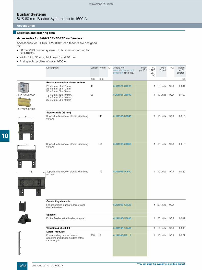
■ Selection and ordering data
Accessories for SIRIUS 3RV2/3RT2 load feeders
Accessories for SIRIUS 3RV2/3RT2 load feeders are designed for: • 60 mm 8US busbar system (Cu busbars according to
DIN 46433)• Width 12 to 30 mm, thickness 5 and 10 mm• And special profiles of up to 1600 A
Description Length Width DT Article No.www.siemens.com/product?Article No.
Priceper PU
PU(UNIT,
SET,M)
PS*/P. unit
PG Weightper PU
approx.
mm mm kg
8US1921-2BE00
8US1921-2BF00
Busbar connection pieces for bars
20 x 5 mm, 20 x10 mm, 25 x 5 mm, 25 x10 mm, 30 x 5 mm, 30 x 10 mm
40 8US1921-2BE00 1 6 units 1CU 0.234
12 x 5 mm, 12 x 10 mm, 15 x 5 mm, 15 x 10 mm,20 x 5 mm, 20 x 10 mm
55 8US1921-2BF00 1 12 units 1CU 0.160
Support rails (35 mm)
Support rails made of plastic with fixing screws
45 8US1998-7CB45 1 10 units 1CU 0.015
Support rails made of plastic with fixing screws
54 8US1998-7CB54 1 10 units 1CU 0.016
Support rails made of plastic with fixing screws
72 8US1998-7CB72 1 10 units 1CU 0.020
Connecting elements
For connecting busbar adapters and device holders
8US1998-1AA10 1 50 units 1CU
Spacers
Fix the feeder to the busbar adapter 8US1998-1BA10 1 50 units 1CU 0.001
Vibration & shock kit 8US1998-1CA10 1 2 units 1CU 0.008
Lateral modules
For extending busbar device adapters and device holders of the same length
200 9 8US1998-2BJ10 1 10 units 1CU 0.021
10/38 Siemens LV 10 · 2016/2017* You can order this quantity or a multiple thereof.